
FDUL221 Line tester Technical Manual Building Technologies
FDUL221
Line tester
Technical Manual
008250_j_en_-2014-05-14
Building Technologies
Control Products and Systems
Legal notice
Legal notice
Technical specifications and availability subject to change without notice.
© 2005 - 2014 Copyright by Siemens Switzerland Ltd
Transmittal, reproduction, dissemination and/or editing of this document as well as
utilization of its contents and communication thereof to others without express
authorization are prohibited. Offenders will be held liable for payment of damages.
All rights created by patent grant or registration of a utility model or design patent
are reserved.
Issued by:
Siemens Switzerland Ltd.
Infrastructure & Cities Sector
Building Technologies Division
International Headquarters
Gubelstrasse 22
CH-6301 Zug
Tel. +41 41 724-2424
www.siemens.com/buildingtechnologies
Edition: 2014-05-14
Document ID: 008250_j_en_--
2
Building Technologies
Fire Safety
008250_j_en_-2014-05-14
Table of contents
1
1.1
1.2
About this document ......................................................................................5
Technical terms ................................................................................................7
Applicable documents.......................................................................................8
1.3
History of changes ............................................................................................8
2
2.1
Safety ............................................................................................................ 11
Safety instructions .......................................................................................... 11
2.2
Safety regulations for the method of operation ................................................ 13
2.3
Standards and directives complied with ..........................................................14
3
Comparison of software functions ..............................................................15
4
4.1
Introduction .................................................................................................. 17
Line topologies ............................................................................................... 17
4.2
Line separation function .................................................................................. 19
5
5.1
Structure and function ................................................................................. 20
Overview ........................................................................................................ 20
5.1.1
5.1.2
5.2
5.3
Setup.............................................................................................................. 26
5.2.1
Display ............................................................................................ 27
5.2.2
Symbols........................................................................................... 28
5.2.3
5.2.4
LED indication ................................................................................. 29
Button assignment ........................................................................... 29
5.2.5
5.2.6
Connections..................................................................................... 29
Connection to terminal strip.............................................................. 31
5.2.7
Battery compartment........................................................................ 32
Accessories .................................................................................................... 33
5.3.1
5.3.2
5.4
Details for ordering / scope of delivery.............................................. 23
Product version ES .......................................................................... 25
9 V lithium manganese dioxide battery ............................................. 33
MCL-USB adapter FDUZ221 ........................................................... 33
5.3.3
MCL-USB (radio) adapter FDUZ227................................................. 33
Function ......................................................................................................... 34
5.4.1
Power supply ...................................................................................34
5.4.2
5.4.3
User language ................................................................................. 34
'EL' operation mode ......................................................................... 34
5.4.4
5.4.5
Functions in the 'Topology' menu ..................................................... 35
Functions in the 'Configuration' menu ............................................... 36
5.4.6
PC operation.................................................................................... 36
6
6.1
Operation ...................................................................................................... 37
Navigating in the menu tree ............................................................................ 37
6.2
6.1.1
Menu trees for 'EL' operation mode .................................................. 40
The 'device' function ....................................................................................... 42
6.3
6.4
Connecting the line tester to the line ............................................................... 44
Switching the line tester on / off ...................................................................... 46
3
Building Technologies
Fire Safety
008250_j_en_-2014-05-14
6.5
Configuring the line tester ............................................................................... 47
6.6
6.7
Reading in line topology ................................................................................. 47
Viewing line topology ...................................................................................... 48
6.7.1
6.7.2
Loop ................................................................................................ 48
Stub................................................................................................. 49
6.7.3
Sub-stub on loop.............................................................................. 49
6.7.4
6.7.5
Impermissible sub-stubs .................................................................. 50
'Config. sounder base' function ........................................................ 50
6.8
6.9
Starting up a line ............................................................................................ 50
Saving a line topology..................................................................................... 51
6.10
6.11
Opening a saved line topology ........................................................................ 52
Operating the line tester with a PC.................................................................. 52
6.12
6.13
Transferring a saved line topology to a PC...................................................... 53
Switching multiple protocol detectors to FDnet/C-NET mode .......................... 54
6.14
6.15
Table of faults ................................................................................................. 55
Tips for troubleshooting on the detector line .................................................... 57
7
7.1
6.15.1
Error search using the 'bisection' method ......................................... 58
6.15.2
6.15.3
Error search using the 'measure line device' method ........................ 58
Explanation of ground fault measurement (for FDUL221 variant 3
only) ................................................................................................ 59
Maintenance / Repair .................................................................................... 60
Testing the line tester ..................................................................................... 60
7.1.1
Selftest ............................................................................................ 60
7.2
7.1.2
Testing calibration............................................................................ 62
Replacing batteries ......................................................................................... 63
7.3
7.2.1
Service life of the batteries ............................................................... 64
Firmware update ............................................................................................ 65
8
8.1
Specifications ............................................................................................... 67
Technical data ................................................................................................ 67
8.2
Environmental compatibility and disposal ........................................................ 69
Index ............................................................................................................. 70
4
Building Technologies
Fire Safety
008250_j_en_-2014-05-14
About this document
Technical terms
1
1 About this document
Goal and purpose
This document contains all necessary information on the FDUL221 line tester with
firmware version V4.x or higher.
Three variants of the FDUL221 line tester are described.
Variant 1 (RS232) applies to FDUL221 with an RS232 serial interface
Variant 2 (MC link) applies to FDUL221 with an MC link serial interface
Variant 3 (USB interface) applies to FDUL221 with an integrated USB interface
Following the instructions consistently will ensure that the product can be used
safely and without any problems.
Target groups
The information in this document is intended for the following target groups:
Target group
Activity
Qualification
Project Manager
Coordinates the deployment of all persons
and resources involved in the project
according to schedule.
Provides the information required to run the
project.
Has obtained suitable specialist
training for the function and for the
products.
Has attended the training courses
for Project Managers.
Project engineer
Sets parameters for product depending on
specific national and/or customer
requirements.
Checks operability and approves the product
for commissioning at the place of installation.
Is responsible for trouble-shooting.
Has obtained suitable specialist
training for the function and for the
products.
Has attended the training courses
for Product Engineer.
Installation personnel
Assembles and installs the product
components at the place of installation.
Carries out a performance check following
installation.
Has received specialist training in
the area of building installation
technology or electrical
installations.
Commissioning personnel
Configure the product at the place of
installation according to customer-specific
requirements.
Check the product operability and release the
product for use by the operator.
Searches for and corrects malfunctions.
Has obtained suitable specialist
training for the function and for the
products.
Has attended the training courses
for commissioning personnel.
Maintenance personnel
Carries out all maintenance work.
Checks that the products are in perfect
working order.
Searches for and corrects malfunctions.
Has obtained suitable specialist
training for the function and for the
products.
5
Building Technologies
Fire Safety
008250_j_en_-2014-05-14
1
About this document
Technical terms
Conventions for text marking
Markups
Special markups are shown in this document as follows:
Requirement for a behavior instruction
1.
Behavior instruction with at least two operation sequences
2.
–
Version, option, or detailed information for a behavior instruction
Intermediate result of a behavior instruction
End result of a behavior instruction
Numbered lists and behavior instructions with an operation
sequence
X]
Reference to a page number
'Text'
Quotation, reproduced identically
<Key>
Identification of keys
Supplementary information and tips
The 'i' symbol identifies supplementary information and tips for an easier way of
working.
Document identification
The document ID is structured as follows:
ID code
Examples
ID_ModificationIndex_Language_COUNTRY A6V10215123_a_de_DE
-- = multilingual or international
A6V10215123_a_en_-A6V10315123_a_--_--
Date format
The date format in the document corresponds to the recommendation of
international standard ISO 8601 (format YYYY-MM-DD).
Open-source software (OSS) licenses
You will find the license texts for the open-source software embedded in the
product in document A6V10435615. See the chapter 'Applicable documents [
7]'.
6
Building Technologies
Fire Safety
008250_j_en_-2014-05-14
About this document
Technical terms
1.1
1
Technical terms
Term
Explanation
ABS
Acrylonitrile-butadiene-styrene (plastic)
AI
Alarm indicator
AnalogPLUS detector
line
Addressed detector line for AlgoRex AnalogPLUS detectors
ES
Product version
FDnet/C-NET
Addressed detector line for Sinteso/Cerberus detectors
PC Linetester Tool
FXS2017
Line tester software
GW
Gateway
HW
Hardware
Interactive detector line
Addressed detector line for AlgoRex interactive detectors
Collective detector line
Unaddressed detector line
Line device
Devices which can be connected to the detector line
MC link
Maintenance and commissioning link,
Interface to service devices
MS8
Pulse detection technology (addressed); also known as PMT
PC
Personal computer
PSP
Product Support Platform
PP
Polypropylene (plastic)
SIGMALOOP detector
line
Addressed detector line for SIGMASYS detectors
SW
Software
True RMS
True root mean square value of voltage characteristic
Variant 1 (RS232)
FDUL221 with RS232 interface
No. A5Q00004397
Variant 2 (MC link)
FDUL221 with 3.5 mm socket
No. A5Q00022100
Variant 3 (USB interface) FDUL221 with USB interface
No. A5Q00055304
7
Building Technologies
Fire Safety
008250_j_en_-2014-05-14
About this document
1
Applicable documents
1.2
1.3
Applicable documents
Document ID
Title
008331
List of compatibility (for 'Sinteso™' product line)
009052
FS20 Fire detection system - Commissioning, Maintenance,
Troubleshooting
009854
Installation MCL-USB Adapter FDUZ221
A6V10210416
FS720 Fire detection system - Commissioning, Maintenance,
Troubleshooting
A6V10229261
List of compatibility (for 'Cerberus™ PRO' product line)
A6V10323158
Technical manual Modernizing fire detection installations with
multiple protocol detectors
A6V10336734
Installation Radio gateway FDCW221
A6V10347735
Installation MCL-USB adapter (radio) FDUZ227
A6V10395483
Line tester – operating instructions for electricians
A6V10435615
Open-Source Software (OSS) Licenses Line tester FDUL221
History of changes
The reference document's version applies to all languages into which the reference
document is translated.
The first edition of a language version or a country variant may, for example, be
version 'd' instead of 'a' if the reference document is already this version.
The table below shows this document's history of changes:
Modification
index
Edition date
Brief description
j
2014-05-14
'Switching multiple protocol detectors to FDnet/C-NET mode' chapter added
Faults which can occur when migrating collective detector lines added to table of faults
Switching detector lines to FDnet/C-NET added to list of fields of application
'Open-Source Software (OSS) Licenses Line tester FDUL221' added to the applicable
documents
'Specifications' chapter: Siemens standard deleted
Editorial changes made
i
2013-08-15
'Technical data' chapter extended
New chapter explaining ground fault measurement
Editorial changes made
8
Building Technologies
Fire Safety
008250_j_en_-2014-05-14
About this document
History of changes
Modification
index
Edition date
h
2013-05-15
g
2010-04
1
Brief description
Document adapted for firmware version V4.x
Addresses updated
Support for a maximum of 252 addresses
Legal notice added
Editorial changes made
Change to date format in line with ISO 8601 specifications (yyyy-mm-dd format).
New functions and the 'EL' operation mode re-included
New chapters: Introduction, line topologies line separation function, overview, MCL-USB
adapter (radio) FDUZ227 as accessory, user language, 'EL' operation mode, menu trees
for 'EL' operation mode, sub-stub on loop, sub-stub on loop/stub, saving a line topology,
opening a saved line topology, transferring a saved line topology to a PC, table of faults,
tips for troubleshooting on the detector line, error search using the 'bisection' method, error
search using the 'device measurement' method
'Technical terms' chapter amended
'Applicable documents' chapter revised
New variants added to the 'Details for ordering/scope of delivery' chapter
Information on the product version added to the 'Product version ES' chapter
Editorial changes made to the 'Setup' and 'Display' chapters, new figure
Symbols removed, new symbols added, adjustments to text in the 'Symbols' chapter
Editorial changes made to the 'LED indication' chapter, figures added
Additions to the 'Connections' chapter, figures added
Editorial change made to the 'Connection to terminal strip' chapter, figure updated
New figure added to the 'Battery compartment' chapter
'Accessories' chapter updated with 'MCL-USB adapter (radio) FDUZ227'
Application amended in the '9 V lithium manganese dioxide battery' chapter
Text changes in the 'Function' chapter
Editorial changes made to the 'Power supply' chapter, new figure
Text amended in the 'Functions in the 'Topology' menu' chapter and figure changed
Text amended in the 'Functions in the 'Configuration' menu' chapter and figure changed
Text changed in the 'PC operation' chapter
Menu trees shown separately in the 'Navigating in the menu tree' chapter, additional menu
tree for the 'EL' operation mode, text adjusted
Menu trees for 'EL' operation mode
Text changes in 'The 'device' function' chapter
Text amended in the 'Connecting the line tester to the line' chapter, new figures added
Text amended in the 'Switching the line tester on and off' chapter, 'Switching on for
configuration' added, new figures added
Text changed in the 'Configuring the line tester' chapter
Text changed in the 'Read in the line topology' chapter
Text added and changed in the 'Viewing line topology' chapter
Text and figure changed in the 'Loop' chapter
Text and figure changed in the 'Stub' chapter
Text and figure changed in the 'Operating the line tester with a PC' chapter
Editorial changes made to the 'Testing the line tester' chapter
Text and figure changed in the 'Selftest' chapter
'Replacing internal fuses' chapter removed
Text and figure replaced in the 'Replacing batteries' chapter
Text changed in the 'Service life of the batteries' chapter
Variant 3 added to the 'Firmware update' chapter, description added, figure added
Data changed in the 'Technical data' chapter
Text changed in the 'Environmental compatibility and disposal' chapter, figure added
Scope of delivery added to chapter on details for ordering
Suppliers on the Intranet added
Notes relating to version 1 (RS232) and version 2 (MC link) added
9
Building Technologies
Fire Safety
008250_j_en_-2014-05-14
About this document
1
History of changes
Modification
index
Edition date
Brief description
f
2009-10
Editorial changes undertaken
Chapters restructured
Notes relating to version RS232 removed
'Connection to terminal strip' chapter added
e
2007-09
Air humidity changed
Technical terms added
Note in chap. 5.3.1 added
SW update with engineering tool (chap. 6.5)
d
2007-02
Chap. 7 Technical data: Line voltage and humidity corrected
c
2007-02
New version with MC link interface
b
2005-01
Name of division
a
2004-12
Software version 2.5.6
The language versions and country variants produced by a local company have
the same modification index as the corresponding reference document. They are
not however included in the table below.
The table below shows the published language versions with the corresponding
modification index:
Modification index
en_--
de_--
fr_--
it_--
es_--
j
X
X
X
X
X
i
X
X
X
X
X
h
X
X
X
X
X
g
X
X
X
X
X
f
X
X
X
X
X
e
X
X
X
X
X
d
X
X
X
X
X
c
X
X
X
X
X
b
X
X
X
X
X
a
X
X
X
X
X
X = published
– = no publication with this modification index
10
Building Technologies
Fire Safety
008250_j_en_-2014-05-14
Safety
Safety instructions
2
2 Safety
2.1
Safety instructions
The safety notices must be observed in order to protect people and property.
The safety notices in this document contain the following elements:
Symbol for danger
Signal word
Nature and origin of the danger
Consequences if the danger occurs
Measures or prohibitions for danger avoidance
Symbol for danger
This is the symbol for danger. It warns of risks of injury.
Follow all measures identified by this symbol to avoid injury or death.
Additional danger symbols
These symbols indicate general dangers, the type of danger or possible
consequences, measures and prohibitions, examples of which are shown in the
following table:
General danger
Explosive atmosphere
Voltage/electric shock
Laser light
Battery
Heat
Signal word
The signal word classifies the danger as defined in the following table:
Signal word
Danger level
DANGER
DANGER identifies a dangerous situation, which will result directly in death or
serious injury if you do not avoid this situation.
WARNING
WARNING identifies a dangerous situation, which may result in death or serious
injury if you do not avoid this situation.
CAUTION
CAUTION identifies a dangerous situation, which could result in slight to
moderately serious injury if you do not avoid this situation.
NOTICE
NOTICE identifies possible damage to property that may result from nonobservance.
11
Building Technologies
Fire Safety
008250_j_en_-2014-05-14
2
Safety
Safety instructions
How risk of injury is presented
Information about the risk of injury is shown as follows:
WARNING
Nature and origin of the danger
Consequences if the danger occurs
Measures / prohibitions for danger avoidance
How possible damage to property is presented
Information about possible damage to property is shown as follows:
NOTICE
Nature and origin of the danger
Consequences if the danger occurs
Measures / prohibitions for danger avoidance
12
Building Technologies
Fire Safety
008250_j_en_-2014-05-14
Safety
Safety regulations for the method of operation
2.2
2
Safety regulations for the method of operation
National standards, regulations and legislation
Siemens products are developed and produced in compliance with the relevant
European and international safety standards. Should additional national or local
safety standards or legislation concerning the planning, assembly, installation,
operation or disposal of the product apply at the place of operation, then these
must also be taken into account together with the safety regulations in the product
documentation.
Electrical installations
WARNING
Electrical voltage
Electric shock
Work on electrical installations may only be carried out by qualified
electricians or by instructed persons working under the guidance and
supervision of a qualified electrician, in accordance with the electrotechnical
regulations.
Wherever possible disconnect products from the power supply when carrying
out commissioning, maintenance or repair work on them.
Lock volt-free areas to prevent them being switched back on again by mistake.
Label the connection terminals with external external voltage using a
'DANGER External voltage' sign.
Route mains connections to products separately and fuse them with their own,
clearly marked fuse.
Fit an easily accessible disconnecting device in accordance with IEC 60950-1
outside the installation.
Produce earthing as stated in local safety regulations.
Assembly, installation, commissioning and maintenance
If you require tools such as a ladder, these must be safe and must be intended
for the work in hand.
When starting the fire control panel ensure that unstable conditions cannot
arise.
Ensure that all points listed in the 'Testing the product operability' section below
are observed.
You may only set controls to normal function when the product operability has
been completely tested and the system has been handed over to the customer.
13
Building Technologies
Fire Safety
008250_j_en_-2014-05-14
2
Safety
Standards and directives complied with
Testing the product operability
Prevent the remote transmission from triggering erroneously.
If testing building installations or activating devices from third-party companies,
you must collaborate with the people appointed.
The activation of fire control installations for test purposes must not cause
injury to anyone or damage to the building installations. The following
instructions must be observed:
–
Use the correct potential for activation; this is generally the potential of the
building installation.
–
–
Only check controls up to the interface (relay with blocking option).
Make sure that only the controls to be tested are activated.
Inform people before testing the alarm devices and allow for possible panic
responses.
Inform people about any noise or mist which may be produced.
Before testing the remote transmission, inform the corresponding alarm and
fault signal receiving stations.
Modifications to the system design and the products
Modifications to the system and to individual products may lead to faults,
malfunctioning and safety risks. Written confirmation must be obtained from
Siemens and the corresponding safety bodies for modifications or additions.
Modules and spare parts
Components and spare parts must comply with the technical specifications
defined by Siemens. Only use products specified or recommended by
Siemens.
Only use fuses with the specified fuse characteristics.
Wrong battery types and improper battery changing lead to a risk of explosion.
Only use the same battery type or an equivalent battery type recommended by
Siemens.
Batteries must be disposed of in an environmentally friendly manner. Observe
national guidelines and regulations.
Disregard of the safety regulations
Before they are delivered, Siemens products are tested to ensure they function
correctly when used properly. Siemens disclaims all liability for damage or injuries
caused by the incorrect application of the instructions or the disregard of danger
warnings contained in the documentation. This applies in particular to the following
damage:
Personal injuries or damage to property caused by improper use and incorrect
application
Personal injuries or damage to property caused by disregarding safety
instructions in the documentation or on the product
Personal injury or damage to property caused by poor maintenance or lack of
maintenance
2.3
Standards and directives complied with
A list of the standards and directives complied with is available from your Siemens
contact.
14
Building Technologies
Fire Safety
008250_j_en_-2014-05-14
Comparison of software functions
3
3 Comparison of software functions
The table below displays the main differences in terms of functionality for the
following software:
Line tester FDUL221
FDUL221 line tester in 'EL' operation mode
'PC Linetester Tool FXS2017' software
FDUL221
FDUL221-EL
FXS2017 Function and description
Localizing line devices
The internal alarm indicator for the line devices can be activated.
All line devices on
All line devices off
Selected line device on
Line device with error
Line device at the end of a stub line
External AI of the selected line device*
The external alarm indicator of the selected line device is activated automatically.
Summary
List of the types of line devices used.
Overall measurement of the detector line
Resistance measurements for the entire detector line.
Partial measurement of the detector line*
Resistance measurements between start of line and individual line device.
See also chapter 'Error search using the 'measure line device' method [
__
58]'.
MC link/FDUD29x support
Information on the individual line device can be displayed on the FDUD29x detector tester (e.g.
the customer text recorded via the 'PC Linetester Tool FXS2017' software or the topology
number). The line device outputs can be activated.
__
Searching for and configuring the sounder base
The sounder base is configured in such a way that it can subsequently be activated via the
corresponding function in the 'Devices' menu. This configuration is retained and only needs to be
carried out once.
The 'Config Buzzers' command is only required in order to find the sounder base each time the
detector line is read in for existing systems with sounder bases manufactured prior to 2007.
__
Converting the detector line
Multiple protocol detectors (e.g. FDOOT241-Ax) can be switched to FDnet operation. In order for
this to happen, the detector line is started up repeatedly.
__
Device status information
Details can be found in the 'The 'device' function [
__
Controlling switching outputs of the line devices
Details can be found in the 'The 'device' function [
__
41]' chapter.
41]' chapter.
Resetting D-Bus addresses
Set all D-Bus addresses to 0. This function is only required in special cases (e.g. when
commissioning the FDCW221 radio gateway).
__
__
__
Assigning D-Bus addresses
The D-Bus addresses for all line devices are set according to the topology address. This is also
possible with offset.
Saving line topologies
It is possible to save several line topologies in the line tester.
See also chapter 'Saving a line topology [
__
__
51]'.
Opening a saved line topology
The saved topology can be transferred using the 'PC Linetester Tool FXS2017' software and sent
by e-mail, for example.
15
Building Technologies
Fire Safety
008250_j_en_-2014-05-14
3
Comparison of software functions
FDUL221
FDUL221-EL
__
FXS2017 Function and description
__
Selftest
The settings are automatically checked during the selftest.
See also chapter 'Testing the line tester [
__
__
__
__
60]'.
Customer texts
Customer texts (in the hardware tree at the 'Devices' level) can be recorded.
Data export in PDF, CSV, FSM formats
Export function of the read-in topologies, e.g. to be able to keep a record of installed devices.
*Possible with firmware version V4.x.x or higher
Function available
__ Function not available
FDUL221 Standard
FDUL221-EL 'EL' operation mode
FXS2017 'PC Linetester Tool FXS2017' software
16
Building Technologies
Fire Safety
008250_j_en_-2014-05-14
Introduction
Line topologies
4
4 Introduction
The basics of detector lines are described below. An understanding of the basics is
a prerequisite for operating the FDUL221 line tester.
4.1
Line topologies
In the FDnet/C-NET, the following topologies are admissible.
Loop
Stub
Sub-stubs on loop
Permissible topologies
No other topologies are admitted. The 'Sub-stub on sub-stub' topology in particular
is not permitted.
Sub-stub on sub-stub with a loop
Sub-stub on stub
Impermissible topologies
17
Building Technologies
Fire Safety
008250_j_en_-2014-05-14
4
Introduction
Line topologies
Technical specifications
All FDnet/C-NET devices have an integrated line separator.
Only one stub may branch off between two adjacent line devices.
When there are several stubs next to one another, a line separator FDCL221
must be connected between each one.
Maximum number of stubs/loops:
Max. number of stubs/loops
(sub-stubs)
Loop resistance
Rcable + Riso
Pure cable resistance
Rcable
5
< 240
< 180
10
< 210
< 150
20
< 150
< 100
40
< 100
< 60
Number of sub-stubs depends on line resistance
Rcable: Pure cable resistance of loop (measured on the loop terminal)
Riso: Total of separator resistances of line devices on loop (0.5
per line device)
18
Building Technologies
Fire Safety
008250_j_en_-2014-05-14
Introduction
Line separation function
4.2
4
Line separation function
All FDnet/C-NET devices have an integrated line separator.
It has two functions:
Short-circuit and open line monitoring
Allows branching of stubs between two FDnet/C-NET devices
Short-circuit monitoring
In the case of a short-circuit on the detector line, the line separator automatically
isolates the faulty line section. This is to ensure that, in the case of a short-circuit,
only the faulty line section fails, not the complete detector line.
Open line
If the detector line is a loop, no line devices fail in the case of open line.
Branching off from a stub
Only one stub is permitted between two FDnet/C-NET devices.
If there is more than one stub between two FDnet/C-NET devices, a line
separator must be fitted between the stubs.
Use of line separators on a loop
19
Building Technologies
Fire Safety
008250_j_en_-2014-05-14
5
Structure and function
Overview
5 Structure and function
Various functions are available depending on which software is installed: A
comparison of the functions can be found in chapter 'Comparison of software
functions [ 15]'.
5.1
Overview
The line tester FDUL221 serves for system diagnostics on an addressed detector line.
Reads the line topology
Detects cable errors
– Short-circuit
– Open line
– Ground fault
– Resistors
Measures resistances
Shows the arrangement of the line devices on the detector line
Shows the current status of the line devices
– Detects errors
– Shows the address
– Allocates an address in the event of double assignment or missing address
Saves line topologies in 'EL' operation mode
Communicates with the 'PC Linetester Tool FXS2017' software
The FDUL221 line tester is controlled by buttons.
If a line device is connected or removed later, the line topology previously read in is
not updated automatically.
The FDUL221 line tester can be operated independently or with the ’PC Linetester
Tool FXS2017’ software.
Features of the FDUL221 line tester
Battery or mains operation
Multi-line display
Backlight
Loadable language variants
Automatic address correction
Clearly arranged operating and indication elements
Save read-in topologies
Generate a report for the read-in topologies
Transfer reports to a connected PC using the ’PC Linetester Tool FXS2017’ software
Fields of application
Addressed detector line (FDnet/C-NET)
Recognition of the FDnet/C-NET devices
Recognition of the line topology
Error search and diagnosis
Installation (control and acceptance)
Interface between FDnet/C-NET and PC
Switching detector lines with alternative protocol to FDnet/C-NET detector lines
20
Building Technologies
Fire Safety
008250_j_en_-2014-05-14
Structure and function
Overview
5
Connections to the detector line and PC
The following figure shows the connection between the FDUL221 and the PC for
different variants of the FDUL221 line tester.
Variant 3
FDUL221
POW ER
DC IN2 4 V
A
E ART H
PC
B
USB
Variant 2
FDUL221
POW ER
DC IN2 4 V
A
E ART H
FDUZ221
FDUZ227
B
PC
Variant 1
FDUL221
POW ER
DC IN2 4V
A
E ART H
PC
B
RS232
FDUD29x
FDnet / C-NET
Addressed detector line with testers
Variant 3
Direct PC connection with cable to USB interface
Variant 2
PC connection via FDUZ227/FDUZ221
Variant 1
Direct PC connection with cable to RS232 interface
21
Building Technologies
Fire Safety
008250_j_en_-2014-05-14
5
Structure and function
Overview
'PC Linetester Tool FXS2017' software
The 'PC Linetester Tool FXS2017' software enables all the functions of the
FDUL221 to be carried out from the PC.
Multilingual user interface
Read-in, display and save lines
Manage files
Graphical representation of the line
Display detailed information about the devices
The 'PC Linetester Tool FXS2017' software is supplied on a CD with the FDUL221
line tester or can be downloaded from the Intranet1.
1) obtain
from: Customer Support Center/PSP Product Support Platform CSC
address: https://intranet.sbt.siemens.com/fs/CSC/
22
Building Technologies
Fire Safety
008250_j_en_-2014-05-14
Structure and function
Overview
5
'EL' operation mode
The FDUL221 line tester can be used in 'EL' operation mode by electricians. In the
'EL' operation mode, detector lines can be read in, checked and saved.
To change the operation mode, a firmware update must be carried out on the
FDUL221 line tester [ 64].
Special operating instructions document A6V10395483 can be downloaded from
the Intranet1 for the 'EL' operation mode. See also 'Applicable documents [ 7]'.
The firmware and the 'PC Linetester Tool FXS2017' software is supplied on a CD
with the FDUL221 line tester or can be downloaded from the Intranet1.
1) obtain
from: Customer Support Center/PSP Product Support Platform CSC
address: https://intranet.sbt.siemens.com/fs/CSC/
5.1.1
Details for ordering / scope of delivery
With the order number A5Q00004397, the latest variant of the FDUL221 line
tester is always supplied with the stated scope of delivery.
Details for ordering and scope of delivery for variant 3 (USB) with
ES 10
Designation
Type
Order no.
Line tester, complete
FDUL221
A5Q00004397
Scope of delivery
FDUL221 line tester with USB connection
(A5Q00055304)
FDUL221-A line connection kit (with terminal strip)
FDUL221-B power unit kit (network adapter for power
supply)
FDUL221-D PC software on CD1
– Software: 'PC Linetester Tool FXS2017'
– Software: 'Line tester firmware updater'
– File: Operating instructions
USB cable type A – type B, 1.8 m, black (A5Q00020783)
Technical manual, language: English (document 008250)
Operating instructions for electricians, language:
English/German (document A6V10395483)
Case
1Also obtain on Intranet from Customer Support Center/PSP Product Support Platform
=>https://intranet.sbt.siemens.com/fs/CSC/
Details for ordering and scope of delivery for variant 2 (MC link)
Designation
Type
Order no.
Line tester, complete
FDUL221
A5Q00004397
Scope of delivery
FDUL221 line tester (A5Q00022100)
FDUL221-A line connection kit (with terminal strip)
FDUL221-B power unit kit (network adapter for power
supply)
FDUL221-D PC software on CD1
– Software: 'PC Linetester Tool FXS2017'
– Software: 'Line tester firmware updater'
– File: Operating instructions
Technical manual, language: English (document 008250)
Case
1Also obtain on Intranet from Customer Support Center/PSP Product Support Platform
=>https://intranet.sbt.siemens.com/fs/CSC/
23
Building Technologies
Fire Safety
008250_j_en_-2014-05-14
5
Structure and function
Overview
Details for ordering and scope of delivery for variant 1 (RS232)
Designation
Type
Order no.
Line tester, complete
FDUL221
A5Q00004397
Scope of delivery
FDUL221 line tester with RS232 connection
(A5Q00004397)
FDUL221-A line connection kit
FDUL221-B power unit kit (network adapter for power
supply)
FDUL221-C PC cable (RS232)
FDUL221-D PC software on CD1
– Software: 'PC Linetester Tool FXS2017'
– Software: 'Line tester firmware updater'
– File: Operating instructions
Technical manual, language: English (document
008250)
Case
1Also obtain on Intranet from Customer Support Center/PSP Product Support Platform
=>https://intranet.sbt.siemens.com/fs/CSC/
Spare parts
Designation
Type
Order no.
Comment
Line connection set
FDUL221-A A5Q00008436 _
Power unit set
FDUL221-B A5Q00008437 _
USB cable type A – type B,
1.8 m, black
_
Adapter cable
FDUD292-A A5Q00004990 MC link, use with FDUZ221/FDUZ227
PC cable (RS232)
FDUL221-C A5Q00008438 For variant 1 only (RS232)
A5Q00020783 _
24
Building Technologies
Fire Safety
008250_j_en_-2014-05-14
Structure and function
Overview
5.1.2
5
Product version ES
The product version ES provides the technical status of a device in terms of
software and hardware. The product version is provided as a two-digit number.
You will find the details of your device's product version:
On the packaging label
On the product label or the type plate
Product version on the packaging label
Details of the product version can be found directly on the packaging label in the
barcode:
ES
Example of a packaging label with details of the product version
Product version on the product label and the type plate
Details of the product version can be found after the device order number:
04
ES
Example of a product label with details of the product version
Depending on the product and various approvals, the product labels may differ in
terms of the information type and layout.
Look for your device's order number on the product label.
You will find the product version after the order number.
25
Building Technologies
Fire Safety
008250_j_en_-2014-05-14
5
Structure and function
Setup
5.2
Setup
The FDUL221 line tester is built in a plastic housing. The power is supplied by
batteries or with the FDUL221-B power unit.
Setup
Item
Symbol/
Description
Function
Element
1
Display
2
LED red
Adjustable backlight and contrast
Scrolling plain text and symbol display
Flashes slowly in the event of an error during startup
Flashes rapidly when PC is connected
3
LED green
Flashes faintly during normal operation
Flashes brightly when reading in the line topology or
when PC is connected
Lights up when scrolling
4
Up/down buttons
Scrolling (up/down) between and within the menus
Scrolling (right/left) within a function, e.g. in Device
Info or in LCD Setup
5
OK button
Confirming a selection, e.g. entering a menu or a
function
Starting a procedure, e.g. activating tests
Activating a function, e.g. switching relays, sounds
and alarm indicators
6
Exit button
Quitting a function or a menu
Cancelling a procedure
Starting the 'Configuration' menu tree (together with
the 'on/off' switch)
7
B (+) red
Connection for line end for a loop
B (-) black
8
A (+) red
A (-) black
Connection for line start for a loop/stub and for a single
line device
26
Building Technologies
Fire Safety
008250_j_en_-2014-05-14
Structure and function
Setup
Item
Symbol/
Description
Function
9
Socket
External power supply via the supplied FDUL221-B
power unit (DC 24 V, 625 mA)
10
On/Off switch
I = On
5
Element
O = Off
11
Socket
Connection for the ground wire or shielding
'Yellow/green'
12
5.2.1
USB connection
type B
Connection to PC (in the case of older FDUL221 line
testers also RS232 interface or MC link)
Display
The FDUL221 line tester has a 4-line display with 20 characters per line.
Features
Adjustable backlight
Adjustable contrast
Automatic adjustment of the vertical and horizontal scroll function with the
buttons
Display of plain text and symbols
27
Building Technologies
Fire Safety
008250_j_en_-2014-05-14
5
Structure and function
Setup
5.2.2
Symbols
The table below lists the displayed symbols and their meaning.
Symbol
Meaning
Battery operation
The level shown in the symbol indicates the charge state of the partially
discharged batteries
Example:
Symbol on left for low battery charge state
Symbol on right for high battery charge state
External power supply (mains operation)
Cursor position displays
Down arrow Start of stub line
Up arrow End of stub line
No symbol The line device is on a loop
Shows the previous line device
Line device was removed after reading in the topology
Error/fault on a line device
Line device was replaced after being removed
Line device displays an alarm
Line device is on a sounder base
Line device on a loop or stub
Last line device on the stub
First line device on the sub-stub
Line device on a sub-stub
Last line device on the sub-stub
Single line device on a stub
Ground fault
28
Building Technologies
Fire Safety
008250_j_en_-2014-05-14
Structure and function
Setup
5.2.3
5
LED indication
The LEDs indicate the operating condition of the FDUL221 line tester.
Element
Description
Function
LED red
Flashes slowly
Error when starting up the FDUL221 line tester
LED red
Flashes rapidly
Connection to PC, e.g. download
LED green
Flashes weakly Normal operation
LED green
Flashes brightly Reading in the line topology
LED green
Lit up
LED green
Flashes rapidly
buttons pressed
Connection to PC, e.g. download
See also
Setup [
5.2.4
26]
Button assignment
Different functions are assigned to the command buttons.
Symbol
Button
Function
Up
Upward movement between and within the menus
Movement to the right within a function, e.g. in
Device Info or in LCD Setup
Down
Downward movement between and within the menus
Movement to the left within a function, e.g. in
Device Info or in LCD Setup
OK
Exit
5.2.5
Confirming a selection, e.g. entering a menu or a
function
Starting a procedure, e.g. activating tests
Activating a function, e.g. switching relays, sounds
and alarm indicators
Quitting a function or a menu
Cancelling a procedure
Starting in configuration mode (together with the
'on/off' switch)
Connections
Connection for external power supply
For the power supply, only connect the FDUL221-B power unit kit to the
socket.
USB connection to the PC
Connect the USB cable to the
socket to connect to the PC.
Ground connection
Connect the ground wire/shielding to the yellow/green
socket and connect
the other end to the ground potential.
29
Building Technologies
Fire Safety
008250_j_en_-2014-05-14
5
Structure and function
Setup
Detector line connections
NOTICE
Connecting the FDUL221 line tester incorrectly may damage the hardware.
Connecting the fire detection installation and the FDUL221 line tester to the
detector line at the same time can result in irreparable damage to the line
interface or the FDUL221 line tester.
Only connect the line tester once the detector line has been separated from
the fire detection installation.
Connect the detector line which is separate from the fire control panel
according to the following figures.
Connect both ends of the line to the
Connection for a loop
sockets on the FDUL221 line tester.
Connection for a stub or a single line device
Connection for a loop
Connect the ends of the feed line to line 'A'.
Connect the ends of the return line to line 'B'.
Connection for a stub or a single line device
Connect the ends of the line to line 'A'.
30
Building Technologies
Fire Safety
008250_j_en_-2014-05-14
Structure and function
Setup
5.2.6
5
Connection to terminal strip
The supplied terminal strip makes it easier to connect a detector line.
1
Stich 1 Loop
1_
L
Stich 2 Lo oop1_ 1+
Loop1_2Stich 2
Loop1_2+
Loop1_1- Stich 1
Loop1_1+
Loop2_2- Stich 4
Loop2_2+
Loop2_1- Stich 3
Loop2_1+
Loo
2
1
1_ 2
p1 +
_2op
3
4
5
FDCI200x-A1
FCI2003-A1
6
7
FDUL221
Connection to terminal strip
1 Control panel
5 Terminal plug with feed/return line for the detector line
2 Terminal strip
6 Periphery board or loop extension
3 Measurement line
7 Ground wire/shielding
4 Terminal plug
The feed line for the detector line is directly connected to the terminal strip.
The terminal strip, measurement line and the terminal plug are available.
1. Connect the terminal strip to the sockets on the FDUL221.
Terminal no.
Terminal no.
Terminal no.
Terminal no.
1 is connected to socket A(+) with the terminal plug (red).
2 is connected to socket A(-) with the terminal plug (black).
3 is connected to socket B(+) with the terminal plug (red).
4 is connected to socket B(-) with the terminal plug (black).
2. Loosen the feed line for the detector line on the FDI200x-A1 periphery board or
FCI2003-A1 loop extension and connect the feed line to the terminal strip.
3. Connect the ground wire.
4. To detect shielding errors, connect the shielding to the ground wire.
The FDUL221 line tester is connected to the detector line.
31
Building Technologies
Fire Safety
008250_j_en_-2014-05-14
5
Structure and function
Setup
5.2.7
Battery compartment
The battery compartment is on the underside of the FDUL221 line tester.
It is shut with a removable cover.
Battery compartment
1 Opened battery compartment with symbol indicating the correct location for the two batteries
32
Building Technologies
Fire Safety
008250_j_en_-2014-05-14
Structure and function
Accessories
5.3
5.3.1
5
Accessories
9 V lithium manganese dioxide battery
For supplying radio detectors, radio gateways and
service devices with power
ULTRALIFE Lithium manganese dioxide type
U9VL-J Li/MnO2 9 V, 1.2 Ah battery with pin cover
Compatible with:
– Radio gateway FDCW221
– DOW1171 radio smoke detector
– Radio test set DZW1171
– Line tester FDUL221
– Detector exchanger and tester FDUD292
– Intelligent detector tester FDUD293
Order no.: A5Q00004142
5.3.2
MCL-USB adapter FDUZ221
For connecting FDnet/C-NET devices to a personal
computer
Interface converter for USB on MC link
Compatible with:
– Floor repeater terminal FT2010
– Floor repeater display FT2011
– Radio gateway FDCW221
– Detector exchanger and tester FDUD292
– Intelligent detector tester FDUD293
– Line tester FDUL221
For details, see document 009854 (assembly
instructions)
No longer available, replaced by MCL-USB adapter
(radio) FDUZ227
5.3.3
MCL-USB (radio) adapter FDUZ227
For connecting FDnet/C-NET devices to a personal
computer
Signals can be transmitted to SWING radio devices
via radio
Interface converter for USB on MC link
Compatible with:
– Floor repeater terminal FT2010
– Floor repeater display FT2011
– Radio gateway FDCW221 and FDCW241
– Detector exchanger and tester FDUD292
– Intelligent detector tester FDUD293
– Line tester FDUL221
– Radio manual call point FDM27x
– Radio fire detector FDOOT271
For details, please refer to document A6V10347735
Order no.: S54323-F106-A1
33
Building Technologies
Fire Safety
008250_j_en_-2014-05-14
5
Structure and function
Function
5.4
Function
The functions of the FDUL221 line tester are divided into two independent modes.
Topology
This mode shows all information relating to the connected detector line [
34].
Configuration
This mode shows all information and settings for the FDUL221 line tester.
5.4.1
Power supply
The FDUL221 line tester can be operated via a power unit or with batteries.
Mains operation
The batteries may be inserted during mains operation.
For mains operation, connect the FDUL221-B power unit to the
socket for
external power supply.
The mains operation is shown as a symbol in the display when the FDUL221 is
switched on.
Mains operation
Battery operation
For battery operation, insert two batteries into the battery compartment. Ensure
they are inserted correctly. [ 62]
In the case of battery operation, the charge state of the partially discharged
batteries is shown.
Charge state of the partially discharged batteries
5.4.2
User language
The FDUL221 line tester can be operated with different user languages. To change
the user language, the desired language must be selected during a firmware
update. You will find more information in chapter 'Firmware update [ 64]'.
5.4.3
'EL' operation mode
The FDUL221 line tester can be used in 'EL' operation mode. The 'EL' operation
mode is only intended for use by electricians.
In 'EL' operation mode, the detector lines can be read in, checked and saved.
Changing the operation mode
To change the operation mode, a firmware update must be carried out on the
FDUL221 line tester. The firmware for the 'EL' operation mode is marked with the
suffix 'electrician'. You will find more information in chapter 'Firmware update [ 64]'.
34
Building Technologies
Fire Safety
008250_j_en_-2014-05-14
Structure and function
Function
5.4.4
5
Functions in the 'Topology' menu
The following menus1 and functions1 are available in the 'Topology' menu tree:
Testing the line topology
Reading in the line
Line devices
–
–
Recognizing the line devices
Address
–
–
Series number
Device type
–
Checking the device status
–
–
Error list
Status
–
–
Activating the sounds of audio devices (not in 'EL' operation mode)
Alarm indicators
–
–
Line separation function (not in 'EL' operation mode)
Relay in input/output module (not in 'EL' operation mode)
Manage Memory (only in 'EL' operation mode)
Error
Monitoring
– Open line
–
–
Ground fault
Short-circuit
–
Missing line devices
– New line devices
Config. sounder base (not in 'EL' operation mode)
Type Overview
Reset addresses
1
Depending on the operation mode, not all menus and functions are available.
See also
Navigating in the menu tree [
37]
35
Building Technologies
Fire Safety
008250_j_en_-2014-05-14
5
Structure and function
Function
5.4.5
Functions in the 'Configuration' menu
The following menus1 and functions1 are available in the FDUL221 line tester's
configuration mode:
Setting the LCD display
–
–
Contrast
Light mode
Selftest
– Display
–
–
LEDs
Power supply
–
Internal hardware
–
–
Line driver
Cable/fuse A+
–
–
Cable/fuse ACable/fuse B+
– Cable/fuse BMode: FDnet
– Identification
Load Factory Def. (default settings)
Save & Exit
End
1
Depending on the operation mode, not all menus and functions are available.
See also
Navigating in the menu tree [
5.4.6
37]
PC operation
The FDUL221 line tester can communicate with a PC via cable for the following
tasks:
Firmware update for the FDUL221 line tester
Transferring data from the FDUL221 line tester to a PC
See also
Operating the line tester with a PC [
52]
36
Building Technologies
Fire Safety
008250_j_en_-2014-05-14
Operation
Navigating in the menu tree
6
6 Operation
6.1
Navigating in the menu tree
There are two menu trees.
The 'Topology' menu tree shows all information on the connected detector line.
The 'Configuration' menu tree shows all information and settings on the
FDUL221 line tester.
'EL' operation mode has its own menu trees [
40].
'Topology' menu tree
The detector line is connected [
43].
1. Switch on the FDUL221 line tester.
The software version is briefly shown on the display.
2. Use the
buttons to navigate.
3. Select the following to read in the line topology:
-
For a loop or a sub-stub on a loop, select 'Startup Loop A->B'.
-
For a stub or a single line device, select 'Startup Stub A'.
4. Exit the 'Topology' menu tree by switching the FDUL221 line tester off.
37
Building Technologies
Fire Safety
008250_j_en_-2014-05-14
6
Operation
Navigating in the menu tree
Version ...
FDnet .....
FDUL221
Startup Loop A->B
Startup Stub A
Convert Line
i
Also read in the sub-stub on the loop
Startup Loop A->B
Startup Line
Startup Stub A
Devices
Startup Line
Convert Line
Loop Start
Show device type
Show ID number
Devices
Loop end
Show device type
Show device type
Show ID number
Show ID number
Devices
device type ES: ….
ID number A….
No Error
is branch @cA
Manned/Unmanned
Fault
Measurements
Measure Device
Error details...
(+) -> (+) ...k
(-) -> (-) ...k
(+) ->
(-) ->
(+) -> (-) ...k
Line current …mA
Source 1 state
Source 1 trouble
...Lost devices
Control A
...Added devices
Isolator
Config Buzzers
Types summary
Locate LEDs
Locate devices
All OFF
All ON
…fault
End of stub
Reset D-BUS adr.
Menu tree for 'Topology' for standard operation mode
38
Building Technologies
Fire Safety
008250_j_en_-2014-05-14
Operation
Navigating in the menu tree
6
'Configuration' menu tree
1. To navigate in the 'Configuration' menu tree, press the
button and switch
the FDUL221 line tester on at the same time.
The display shows 'LineTester Config'.
2. Use the
buttons to navigate.
3. Exit the 'Configuration' menu tree via 'Save & Exit' or 'Exit'.
LineTester Config
LCD setup
Contrast
Light mode
ON
OFF
Auto
Selftest
Display
LEDs
Supply
Test Supply
Vbat = .....mV
VL
= .....mV
Internal HW
Test Hardware
UP key: cable test
with loopback plug.
Linedriver
Cablin/Fuse A(+)
Cablin/Fuse A(-)
Cablin/Fuse B(+)
Cablin/Fuse B(-)
Mode: FDnet
SIGMA
Spy
32V
Load Factory Def
Save & Exit
Exit
Menu tree for 'Configuration' for standard operation mode
39
Building Technologies
Fire Safety
008250_j_en_-2014-05-14
6
Operation
Navigating in the menu tree
6.1.1
Menu trees for 'EL' operation mode
1. To navigate in the 'Topology' menu tree, switch the FDUL221 line tester on.
2. To navigate in the 'Configuration' menu tree, press the
button and switch
the FDUL221 line tester on at the same time.
The software version is briefly shown on the display.
3. Use the
buttons to navigate.
'Configuration' menu tree
1. To navigate in the 'Configuration' menu tree, press the
button and switch
the FDUL221 line tester on at the same time.
The display shows 'LineTester Config'.
2. Use the
buttons to navigate.
3. Exit the 'Configuration' menu tree via 'Save & Exit' or 'Exit'.
'Topology' menu tree
The detector line is connected [
43].
1. Switch on the FDUL221 line tester.
The software version is briefly shown on the display.
2. Use the
buttons to navigate.
3. Select the following to read in the line topology:
-
For a loop or a sub-stub on a loop, select 'Startup Loop A->B'.
-
For a stub or a single line device, select 'Startup Stub A'.
4. Exit the 'Topology' menu tree by switching the FDUL221 line tester off.
40
Building Technologies
Fire Safety
008250_j_en_-2014-05-14
Operation
Navigating in the menu tree
6
Topology
Configuration
Version ...
FDnet .....
Memory Usage:.
LineTester Config
FDUL221-EL
.........
..........
.........
LCD setup
Contrast
i
'EL' operation mode
i
Also read in the sub-stub on the loop
Startup Loop A->B
Light mode
ON
OFF
Auto
Startup Line
Startup Stub A
Devices
Startup Line
Mode: Fdnet
SIGMA
32V
Devices
Load Factory Def.
Loop start
Show device type
Manage Memory
Save & Exit
Show device type
Exit
Show ID number
Show ID number
Loop end
Show device type
… used
Erase single
Erase all
Show ID number
…fault
Measurements
(+) -> (+) ...k
(-) -> (-) ...k
Devices
(+) ->
device type ES: ….
(-) ->
ID number A….
(+) -> (-) ...k
No Error
Line current …mA
is branch @cA
...Lost devices
Manned/Unmanned
...Added devices
Measure Device
Types summary
Locate devices
All OFF
All ON
…fault
End of stub
Save Topology
Menu trees for 'EL' operation mode
41
Building Technologies
Fire Safety
008250_j_en_-2014-05-14
6
Operation
The 'device' function
6.2
The 'device' function
The 'Devices' function is not available in 'EL' operation mode.
Meaning of the lines
The display shows the function of the line device in four lines. The internal and
external alarm indicator of the selected line device flash.
Line
Display
1
Input status
Input fault
Line device fault
Outputs A, B, C, D
Disconnector status
Output of external alarm indicator
2
Address for line device
Status of first line
3
Name of the line device
Cursor (position display) for editing
4
The serial number (identification number) and product version (ES) of the line device
The position display when editing in plain text
If a line device has already been operated on a control panel, it will not be
initialized again. The existing configuration is adopted by the control panel.
Example:
In the case of the FC20xx, FC72x or AlgoRex fire control panels, the inputs of a
FDCIO222 that are not used (= not linked) are directly set to 'off' in the line device.
The input status of the FDUL221 line tester is therefore not displayed.
Meaning of inputs
The display depends on the line device connected. The following table shows how
the FDUL221 line tester displays inputs:
Danger level
Meaning
Display
Input status
Display
Input status
Display
Not active
'-'
Active
'a'
0
No danger
'0'
Free
'-'
1
Possible danger
'1'
Resetting /
Not ready
'r'
2
Probable danger
'2'
Initial activation /
testing
'a'
3
Most likely danger
'A'
Alarm activation
'A'
42
Building Technologies
Fire Safety
008250_j_en_-2014-05-14
Operation
6
The 'device' function
Assignment of outputs
The assignment of the outputs A, B, C, D depends on the line device.
Line device
Output A
Output B
Output C
Output D
Notes
-
-
-
-
Not available for
all line devices
-
-
-
-
-
-
-
-
Point detector (thermal /
optical)
Ext. AI
Manual call point
Ext. AI
-
Linear smoke detector
Ext. AI
Flame detector
Ext. AI
Input/
output modules
Activation of
relay
Activation of
relay
Activation of
relay
Activation of
relay
If output
available
Transponder
Activation of
relay
Activation of
relay
Activation of
relay
Activation of
relay
If configured as
output
Aspirating smoke detector
Reset
Day / Night
Standby
Normalize
Video fire controller
Start receptacle
Start receptacle
Alarm sounder
Ext. AI
Activation of
evacuation
signal
Activation of
alarm signal
Alarm sounder with additional
optical indicator
Ext. AI
Activation of
evacuation
signal
Activation of
alarm signal
Sounder interbase
Ext. AI
Activation of
evacuation
signal
Activation of
alarm signal
Sounder interbase with
additional optical indicator
Ext. AI
Activation of
evacuation
signal
Activation of
alarm signal
Addressable alarm indicator
Ext. AI
-
-
-
-
Radio gateway
Ext. AI
-
-
-
-
Activation of
evacuation
signal
Activation of
alarm signal
-
-
-
-
-
-
Activating the
beacon
-
Activating the
beacon
-
-
-
43
Building Technologies
Fire Safety
008250_j_en_-2014-05-14
6
Operation
Connecting the line tester to the line
6.3
Connecting the line tester to the line
NOTICE
The detector line is ready during testing.
Connecting the FDUL221 line tester incorrectly may damage the hardware.
Detector lines, line sections or individual line devices to be tested must not be
simultaneously connected to the control panel.
Observe the polarity of the connections when connecting the FDUL221 line
tester.
You will find more detailed information in the fire detection system documentation.
Connection for loop
Connection for stub
The lines to be checked must be disconnected from the control panel while
testing is taking place.
1. Check that the lines are disconnected from the control panel and ensure that
they remain disconnected during testing.
2. Connect the ground wire and connect the other end with the ground potential.
3. To detect shielding errors, connect the shielding to the ground wire.
For a loop:
1. Connect both ends of the line to the FDUL221 line tester.
2. Connect the ends of the feed line to line 'A'.
3. Connect the ends of the return line to line 'B'.
For a stub or a single line device:
Connect the ends of the line to line 'A'.
44
Building Technologies
Fire Safety
008250_j_en_-2014-05-14
Operation
Connecting the line tester to the line
6
Connection to terminal strip on FDI200x-A1 periphery board or
FCI2003-A1 loop extension
The terminal strip makes it easier to connect a detector line.
1
Stich 1 Loop
1_
L
Stich 2 Lo oop1_ 1+
Loop1_2Stich 2
Loop1_2+
Loop1_1- Stich 1
Loop1_1+
Loop2_2- Stich 4
Loop2_2+
Loop2_1- Stich 3
Loop2_1+
Loo
2
1
op
1_ 2
p1 +
_2-
3
4
5
FDCI200x-A1
FCI2003-A1
6
7
FDUL221
Connection to terminal strip
1 Control panel
5 Terminal plug with feed/return line for the detector line
2 Terminal strip
6 Periphery board or loop extension
3 Measurement line
7 Ground wire/shielding
4 Terminal plug
The feed line for the detector line is directly connected to the terminal strip.
The terminal strip, measurement line and the terminal plug are available.
1. Connect the terminal strip to the sockets on the FDUL221 line tester.
Terminal no.
Terminal no.
Terminal no.
Terminal no.
1 is connected to socket A(+) with the terminal plug (red).
2 is connected to socket A(-) with the terminal plug (black).
3 is connected to socket B(+) with the terminal plug (red).
4 is connected to socket B(-) with the terminal plug (black).
2. Loosen the feed line for the detector line on the FDI200x-A1 periphery board or
FCI2003-A1 loop extension and connect the feed line to the terminal strip.
3. Connect the ground wire.
4. To detect shielding errors, connect the shielding to the ground wire.
The FDUL221 line tester is connected to the detector line.
See also
Setup [
26]
Connections [
29]
45
Building Technologies
Fire Safety
008250_j_en_-2014-05-14
6
Operation
Switching the line tester on / off
6.4
Switching the line tester on / off
ON
Move the
switch into position <I>.
The 'Topology' menu is opened.
The display briefly indicates the firmware version of the FDUL221 line tester
and 'FDnet …'.
Display for 'EL' operation mode
Then the device designation is displayed with operation mode and the selection
fields.
Display for 'EL' operation mode
The FDUL221 line tester is ready for operation.
Switching on for configuration
To open the 'Configuration' menu tree press the
button and switch the
switch to the <I> position at the same time.
The 'Configuration' menu is opened.
The indicator in the display changes to the 'Startup Line' menu.
The FDUL221 line tester is in the ’Configuration’ menu.
Switching off
Move the
switch into position <O>.
The indicator goes out.
If working with the FDUL221-B power unit, the power unit can be removed.
See also
Setup [
26]
46
Building Technologies
Fire Safety
008250_j_en_-2014-05-14
Operation
Configuring the line tester
6.5
6
Configuring the line tester
The FDUL221 line tester must be set to the relevant protocol if it is being used on a
detector line. The protocol is permanently set in the 'EL' operation mode and
cannot be configured.
Control panel
Protocol
Mode: FDnet
FC20xx
FDnet
32 V
FC72x
C-NET
32 V
CS114x
FDnet
32 V
SIGMASYS
FDnet
SIGMA
_
FDnet/C-NET
Spy
To configure, proceed as follows:
The FDUL221 line tester is switched off.
1. Hold down the
button and switch the FDUL221 line tester on with the
switch.
The FDUL221 line tester is in the 'Configuration' menu tree.
2. Select 'Mode: FDnet …' using the
buttons.
3. Select the required protocol with the
button.
4. Select further sub menus or a function with the
buttons.
5. Further changes in the sub menu or function can be made in the same way.
6. To quit a sub menu or a function, press the
button.
7. To quit 'Configuration', select 'Save & Exit' or 'Exit'.
The FDUL221 line tester switches to the 'Topology' menu tree.
See also
Navigating in the menu tree [
6.6
37]
Reading in line topology
To read in the line topology, proceed as follows:
1. Disconnect the detector line or the line section from the control panel.
2. Connect the FDUL221 line tester to the detector line or line section. Adhere to
the polarity [ 43].
3. Switch the FDUL221 line tester on [
45].
4. Check whether 'FDnet …' matches the detector line. If not, reconfigure the
FDUL221 line tester [ 47].
5. Select either 'Startup Loop A->B' or 'Startup Stub A'.
6. Press the
button.
The topology is read in and displayed automatically.
47
Building Technologies
Fire Safety
008250_j_en_-2014-05-14
6
Operation
Viewing line topology
6.7
Viewing line topology
To view the line topology, proceed as follows:
1. Use the
buttons to select the 'Devices' sub menu and confirm the
selection with the
button.
The line topology and number of line devices are displayed.
2. Use the
buttons to select either 'Devices on A' or 'Devices on B' and
confirm the selection with the
button.
Depending on the line topology, the line devices are displayed.
3. Select a single line device.
The internal and external alarm indicator of the selected line device flash.
If the 'All ON' selection is active in the 'Locate devices' menu, the internal
alarm indicators of all line devices detected by the FDUL221 line tester
flash.
Technical requirements for line topologies
All FDnet/C-NET devices have an integrated line separator. [ 18]
Only one stub may branch off between two adjacent line devices.
When there are several stubs next to one another, a line separator FDCL221
must be connected between each one.
The following chapters contain examples for line topologies and the display on the
FDUL221 line tester.
6.7.1
Loop
The 'loop' topology is permitted.
Detector line on the control panel
Arrangement of the line devices
Display
The line devices are displayed in the order of the loop. The display shows the
number of the line device in brackets. E.g. [T001] for the first line device. In the
case of the red outlined device, the internal alarm indicator flashes. If an external
alarm indicator is connected to this device, the external alarm indicator also
flashes.
48
Building Technologies
Fire Safety
008250_j_en_-2014-05-14
Operation
Viewing line topology
6.7.2
6
Stub
The 'stub' topology is permitted.
Detector line on the control panel
Arrangement of the line devices
Display
The line devices are displayed in the order of the stub. The display shows the
number of the line device in brackets. E.g. [T001] for the first line device. In the
case of the red outlined devices, the internal alarm indicator flashes. If an external
alarm indicator is connected to these devices, the external alarm indicator also
flashes.
6.7.3
Sub-stub on loop
The 'sub-stub on loop' topology is permitted.
Detector line on the control panel
Arrangement of the line devices
Display
The line devices are displayed in the order of the loop. On the branch to the substub, the line devices are displayed in the order of the sub-stub. The display shows
the number of the line device in brackets. E.g. [T003] for the third line device. In the
case of the red outlined device, the internal alarm indicator flashes. If an external
alarm indicator is connected to this device, the external alarm indicator also
flashes.
49
Building Technologies
Fire Safety
008250_j_en_-2014-05-14
6
Operation
Starting up a line
6.7.4
Impermissible sub-stubs
The following sub-stubs are not permitted:
Sub-stub on stub
Sub-stub on loop without line separation
Sub-stub on sub-stub on loop
Detector line on the control panel
Arrangement of the line devices
Display
The line devices are displayed in the order of the loop/stub. On the branch to the
sub-stub, the line devices are displayed in the order of the sub-stub. The line
devices may be shown with incorrect symbols. The display shows the number of
the line device in brackets. E.g. [T003] for the third line device. In the case of the
red outlined devices, the internal alarm indicator flashes. If an external alarm
indicator is connected to these devices, the external alarm indicator also flashes.
6.7.5
'Config. sounder base' function
The 'Config Buzzers' function is not available in 'EL' operation mode.
The ’Config Buzzers’ function is only used for very old sounder bases
(manufactured prior to 2007). During this process, the outputs of the line detectors
briefly become active.
6.8
Starting up a line
When starting up a line, the detectors are generally not addressed again. The
affected detectors are re-addressed if there are conflicting addresses or
unaddressed devices.
50
Building Technologies
Fire Safety
008250_j_en_-2014-05-14
Operation
Saving a line topology
6.9
6
Saving a line topology
Line topologies can be saved in the 'EL' operation mode. The memory capacity is
limited and divided into 23 spaces. Extensive line topologies can occupy up to 4 spaces.
Position
Display
1
2
3
4
5
6
The line topology is read in.
1. Make sure that you have sufficient memory capacity.
2. Select 'Manage Memory' (pos. 1).
3. To free up memory capacity, delete data that is not required in the menu tree
(pos 2).
4. Navigate to 'Save Topology' in the menu tree.
5. Press the
button (pos. 4).
The saving process begins (pos. 3).
6. Wait until the saving process is complete (pos. 5).
The name of the storage space is displayed, e.g. M3 (pos. 6).
7. Note the assignment of the name to the detector line.
8. Press the
button.
The line topology is saved.
The topologies saved on the FDUL221 line tester can be transferred to a PC using
the 'PC Linetester Tool FXS2017' software.
See also
Transferring a saved line topology to a PC [
Navigating in the menu tree [ 37]
53]
51
Building Technologies
Fire Safety
008250_j_en_-2014-05-14
6
Operation
Opening a saved line topology
6.10
Opening a saved line topology
In 'EL' operation mode, saved line topologies can be opened using the 'PC
Linetester Tool FXS2017' software.
6.11
Operating the line tester with a PC
The FDUL221 line tester can be controlled via a connected PC. The 'PC Linetester
Tool FXS2017' software is supplied with the FDUL221 line tester on CD or can be
downloaded from the Customer Support Center1.
Depending on the variant of the FDUL221 line tester, there are various options for
connecting the line tester to the PC:
Variant 3: Direct connection to USB interface
Variant 2: Connection via FDUZ221/FDUZ227
Variant 1: Connection via RS232 interface
To commission, proceed as follows:
The PC and the 'PC Linetester Tool FXS2017' software are available.
The components for linking the FDUL221 and PC are present.
1. Install the 'PC Linetester Tool FXS2017' software on the PC.
2. Connect the FDUL221 line tester to the PC.
-
For variant 3, use a USB cable.
-
For variant 2 use the FDUZ221 MCL-USB adapter or the MCL-USB
adapter (radio) FDUZ227. Use the supplied cable (MC link and USB) for
the connection.
-
For variant 1, use the RS232 PC cable. The RS232 connection is in the
battery compartment.
3. Connect the FDUL221 line tester to the power supply and switch it on.
-
Ensure that the power supply and the USB connection are not interrupted
during an upload or download.
52
Building Technologies
Fire Safety
008250_j_en_-2014-05-14
Operation
Transferring a saved line topology to a PC
6
4. Start the 'PC Linetester Tool FXS2017' software on the PC.
5. In the 'Read in' menu, select the 'Start reading in' sub menu.
The line tester can be operated from the PC using the 'PC Linetester Tool
FXS2017' software.
You can delete all the files on the FDUL221 line tester with the 'PC Linetester
Tool FXS2017' software.
The USB connection can be affected in areas where there is a high level of EMC
interference. In such cases, use the FDUL221 line tester without the 'PC
Linetester Tool FXS2017' software.
If you have any questions, please contact the Customer Support Center1.
1) Customer
Support Center/PSP Product Support Platform CSC
address: https://intranet.sbt.siemens.com/fs/CSC/
See also
Overview [
6.12
20]
Transferring a saved line topology to a PC
The FDUL221 line tester is in 'EL' operation mode.
The 'PC Linetester Tool FXS2017' software is installed on the PC.
The PC is connected to the FDUL221 line tester by cable.
1. Start the 'PC Linetester Tool FXS2017' software.
2. Select 'FDUL221'.
3. Wait until the data has loaded.
4. Select the 'FDUL221-EL' menu and the 'Upload saved topology' sub menu.
5. Select the storage location.
6. Define the file name.
7. Save the file with 'Save Topology'.
The file is saved.
You can delete all the files on the FDUL221 line tester with the 'PC Linetester
Tool FXS2017' software.
53
Building Technologies
Fire Safety
008250_j_en_-2014-05-14
6
Operation
Switching multiple protocol detectors to
FDnet/C-NET mode
6.13
Switching multiple protocol detectors to
FDnet/C-NET mode
The 'Convert Line' command makes it easier to switch multiple protocol detectors
to FDnet/C-NET mode. When the 'Convert Line' command is used, the detector
line is automatically started up and read in until the number of detectors detected
no longer changes. You will find more information about switching detector lines in
document A6V10323158.
If a collective detector line is switched, the EOL resistor has been removed.
If a collective detector line to which manual call points and point detectors are
connected is switched, the diodes have been removed from the detector bases.
The FDUL221 line tester is in 'Standard' operation mode.
If the FDUL221 line tester is in 'EL' operation mode, the line tester is operated
from a PC with the 'PC Linetester Tool FXS2017' software and the software is
in 'Expert Mode'.
1. Disconnect the detector line or the line section from the control panel.
2. Connect the FDUL221 line tester to the detector line or line section. Adhere to
the polarity [ 43].
3. Switch the FDUL221 line tester on [
45].
4. Check whether 'FDnet …' matches the detector line. If not, reconfigure the
FDUL221 line tester [ 47].
5. Select 'Convert Line'.
6. Press the
button.
The detector line is automatically started up and read in until the number of
detectors detected no longer changes. The process can take several
minutes.
The number of detectors detected and the number of errors are displayed.
See also
Applicable documents [
Table of faults [
7]
54]
54
Building Technologies
Fire Safety
008250_j_en_-2014-05-14
Operation
Table of faults
6.14
6
Table of faults
Below you will find an overview of the errors displayed by the FDUL221 line tester
as well as possible causes and remedies for the errors.
Line device
Line device is shown on the display, the internal and external alarm indicators flash
Position of the line device not detected
Line device is shown on the display with an error
Error display
Possible cause
Remedy
E01 Short
Short-circuit on the detector line. The line separator is open
for the line device shown on the display.
Locate the short-circuit by checking the cable
section behind the line device shown on the
display. In the case of a loop, the location is
also shown as an 'open line'.
E02 Open (+)
Open line on the
line The exact position of the open line
cannot be identified by the FDUL221 line tester.
Check the cable. Search for the faulty location
by disconnecting the detector line and rechecking the cable connection.
Disconnect the return line and restart the
detector line. The open line is located behind
the last line device shown on the display.
E03 Open (-)
Open line on the
Open the loop at one end and restart the
detector line. The open line is located behind
the last line device shown on the display.
E04 Hi leak
High leakage current
line
Check the cable insulation.
In the case of migrated detector lines:
Check whether old line devices are still
installed on the detector line.
The typical leakage current is approx. 300 µA (base current)
and approx. 3 µA per line device.
E05 High cap
a) High line capacity
Check whether EOL elements, e.g.
resistors, are still installed on the detector
line.
Line too long. Reduce the length of the loops
or stubs, e.g. through division.
The maximum line length is 3.3 km for
FS20/FS720, 2.5 km for SIGMASYS and also
depends on the line type.
Rlmax = 240
b) Error during migration, e.g. due to forgotten line device
, Clmax = 750 nF
Replace the affected line device.
55
Building Technologies
Fire Safety
008250_j_en_-2014-05-14
6
Operation
Table of faults
Error display
Possible cause
Remedy
E06 (-) -> EARTH
a)
Search for the ground fault. In particular, note
connections for line devices with grounded
components, shielded cables, etc.
line is grounded
b) The connection for the external AI is grounded
+
_
E07 (+) -> EARTH
(D)
_
line is grounded. The exact position of the error cannot
be identified by the FDUL221 line tester.
?
E08 series R
+
?
+
_
High resistance
+
_
(D)
Find the faulty location by separating the parts
of the detector line and checking the separated
line parts (e.g. ½, ¼, ). Also refer to the tips
on 'Error search' [ 57].
+
_
Resistance in the detector line is too high.
Check the lines and the connection points
(terminals). Ensure that the line is not too long.
Limit values: See error E05
Use the 'Measure Device' menu item.
E09 More err
The error list is limited to a maximum number of error
messages that can be displayed. However, more errors are
available than can be currently displayed.
Rectify the errors displayed and then read in
the detector line again. The errors that were
not originally displayed will then be shown.
E10 >252 dev
There are too many devices on the detector line that has
been read-in. A maximum of 252 devices may be installed
on a FDnet/C-NET detector line.
The read-in loop or stub must be divided into
several loops or stubs with less line devices.
E11 bad TTap
a) A sub-stub is not permitted in this location.
Note: This error number indicates several line devices as
faulty.
A branch is not allowed. Change the wiring.
Ensure that a 'sub-stub on stub' topology has
not been wired. Only one or several individual
sub-stubs can branch from a loop.
b) When switching a collective detector line with manual call Remove the diodes from all detector bases.
points and point detectors, the diodes are still installed in
the detector bases.
E12 >2 TTap
a) Several sub-stubs directly after one another without a
line separator in between are not permitted.
Note: This error number indicates several line devices as
faulty.
Ensure that there is a line device, e.g. a line
separator, between two sub-stubs branching
off from the loop.
Only one sub-stub may branch off from a loop
between two line devices on the detector line.
b) When switching a collective detector line with manual call Remove the diodes from all detector bases.
points and point detectors, the diodes are still installed in
the detector bases.
56
Building Technologies
Fire Safety
008250_j_en_-2014-05-14
Operation
Tips for troubleshooting on the detector line
6
Error display
Possible cause
Remedy
E13 bad EOS
Error on the last line device of a stub: In the case of a
closed line separator, an increased load current is detected
on this line device.
In the case of migrated lines: Check whether a
resistor or a Z diode is still installed on the line
device.
Remove the resistor or the Z diode.
E14 Diode (+)
Diode on the
+
_
E15 Diode (-)
?
Diode on the
+
_
line
?
+
_
line
?
?
+
_
The wire was incorrectly connected to the
terminal for the external alarm indicator
instead of the terminal for the detector line.
Also observe the notices in the 'Error search
using the 'measure line device' method [ 58]'
section.
The wire was incorrectly connected to the
terminal for the external alarm indicator
instead of the terminal for the detector line.
Also observe the notices in the 'Error search
using the 'measure line device' method [ 58]'
section.
E16 Alarm
An alarm has been triggered on the line device.
E.g. in the case of a manual call point, replace
the defective glass insert and close the door.
E17 Defect
The line device is defective.
Replace the line device.
6.15
Tips for troubleshooting on the detector line
Once the detector line has been read in, the FDUL221 line tester detects the
following detector line errors:
Open line
Ground fault
Short-circuit
Shield fault
Shield permeability
Shield ground fault
If a single line device is selected with the FDUL221 line tester, its internal or
external alarm indicator will flash.
If the 'All ON' is selected in the 'Locate devices' menu, the internal/external alarm
indicators of all line devices detected by the FDUL221 line tester flash. In this way,
you can detect line devices that were not detected by the FDUL221 line tester.
57
Building Technologies
Fire Safety
008250_j_en_-2014-05-14
6
Operation
Tips for troubleshooting on the detector line
6.15.1
Error search using the 'bisection' method
The FDUL221 line tester is ready for operation.
1. Separate the lines on a line device in the center of the loop or stub and create
two stubs.
2. Measure each stub.
You will detect the stub with the error.
Divide the faulty stub in the center and connect the previously separated
points.
3. Measure each stub.
This will enable you to identify the area with the error.
4. Proceed as described with the division until you have located the error.
The increasingly smaller sections will enable you to rapidly locate the error.
A
B
A
B
A
B
Error search using the 'bisection' method
6.15.2
Error search using the 'measure line device' method
Recommended for errors E02, E14, E15. Using the measured value you can
determine whether the error lies upstream or downstream of the selected line
device. The location of the error can be rapidly determined through the selection of
line devices.
Proceed as follows:
1. Restart the detector line.
2. Navigate to the desired line device in the line tester display.
3. Press the
button.
4. Select the 'Measure Device' menu item.
5. Perform steps 1 to 4 for more devices if required.
Measure the terminal resistances of the line device in the 'Measurements' menu.
The values displayed are totals. The total value is affected by line resistance and
diodes (e. g. external alarm indicators). Take this into account when analyzing the
measurement.
58
Building Technologies
Fire Safety
008250_j_en_-2014-05-14
Operation
6
Tips for troubleshooting on the detector line
Loop
Plus and minus lines are measured separately
Cable from 'A' and 'B' separated
Diodes are detected and localized (wire 'A' or 'B' and
)
Stub
Only the total resistance is measured
Only used for stub and sub-stub
6.15.3
Explanation of ground fault measurement (for
FDUL221 variant 3 only)
Once you have started up the line, you can identify the ground fault resistance
between (+) and ground as well as (-) and ground using the 'Measurements' menu.
The table below shows three examples:
Ground fault measurement
display
Interpretation
Line ok
Fault at connection with low measured value for (-)
Fault at connection with low measured value for (+)
The line is ok if the value '
OK' is displayed with '(+)
' and '(-)
'.
If 'leak' or 'fault' is displayed, there is a ground fault at the connection with the
lower resistance value to ground. This resistance corresponds to the actual
ground fault resistance.
The resistance at the other connection (the higher value) cannot be interpreted
directly, as it is usually 100 k on account of the internal circuit.
A resistance to ground that exceeds 500 k
can no longer be reliably detected.
If the line is measured manually using a multimeter, the line must be
disconnected from the FDUL221 line tester.
59
Building Technologies
Fire Safety
008250_j_en_-2014-05-14
7
Maintenance / Repair
Testing the line tester
7 Maintenance / Repair
7.1
Testing the line tester
The FDUL221 line tester is set in the factory. This setting cannot be changed by
the user.
During the selftest the settings are tested automatically, by electronically
connecting and measuring reference resistances in the different configuration.
Calibration may also be checked manually.
7.1.1
Selftest
The selftest is not possible in 'EL' operation mode. In this case, change the
operation mode. See chapter: 'Firmware update [ 64]'.
A measuring cable is required for testing.
The FDUL221 line tester is connected to a power supply.
1. Press the
button and switch the FDUL221 line tester on at the same time.
The display shows 'LineTester Config'.
2. Navigate to the 'Selftest' sub menu.
3. Perform the tests according to the information in the display.
The corresponding test result is displayed.
4. To acknowledge a successful test, press the
button 'PASS'.
You are taken to the next test.
5. If the test is not successful, press the
button 'FAIL'.
You are taken to the previous test.
6. Connect the cable according to the instructions during testing. The connections
for the detector lines and ground wire/shielding are labeled accordingly.
7. Rectify the faults displayed.
8. If the fault 'Cablin/Fuse' is displayed, check the cable. If the fuse is the cause of
the error, send the FDUL221 line tester for repair.
Testing procedure
Display
– 'Test Display'
– 'Black lines OK?'
LEDs
–
–
'Test LEDs'
'Red LED steady on?
– 'Green LED blinking?'
Supply
–
–
'Test Supply'
'Vbatt= .....mV'
–
'UL=.....mV'
60
Building Technologies
Fire Safety
008250_j_en_-2014-05-14
Maintenance / Repair
Testing the line tester
7
Internal HW
– 'Test Hardware'
Linedriver
–
'Test Linedriver A(+)'
Cablin/Fuse A(+)
– 'Connect EARTH to A(+)'
Cablin/Fuse A(-)
– 'Connect EARTH to A(-)'
Cablin/Fuse B(+)
– 'Connect EARTH to B(+)'
Cablin/Fuse B(-)
– 'Connect EARTH to B(-)'
'Selftest COMPLETE'
'Exit
Measurement connections
1 Line B (sockets B+ and B-)
2 Line A (sockets A+ and A-)
3 Earth (socket)
See also
Power supply [
34]
61
Building Technologies
Fire Safety
008250_j_en_-2014-05-14
7
Maintenance / Repair
Testing the line tester
7.1.2
Testing calibration
If testing manually, use a digital voltmeter with 'True RMS'.
The table below shows the nominal measured value as a function of the configured
control unit.
Control panel
Mode
Nominal measured value
FS20
FS720
CS114x
FDnet 32 V
DC 28 V ± 5 %
AC 10 V ± 10 %
SIGMASYS
FDnet SIGMA
DC 24 V ± 5 %
AC 8 V ± 10 %
62
Building Technologies
Fire Safety
008250_j_en_-2014-05-14
Maintenance / Repair
Replacing batteries
7.2
7
Replacing batteries
The charge state of the batteries is indicated on the right of the FDUL221 line
tester's display. To ensure the faultless functionality of the FDUL221 line tester,
weak batteries must be replaced by new ones.
WARNING
Short-circuit as a result of incorrectly inserting batteries
Warming of batteries and risk of fire
When inserting battery, note polarity.
Two new, undamaged batteries, order number A5Q00004142, are available.
1. Switch off the FDUL221 line tester.
2. Disconnect the FDUL221 line tester from the detector line.
3. Open the battery compartment on the back of the FDUL221 line tester.
-
Slide the cover out of the catch.
-
Remove the cover.
4. Remove the batteries.
5. Move the pin cover from the new batteries to the old ones.
6. Insert two new batteries into the battery compartment and ensure they are
inserted correctly. The batteries must have a space between them so that the
battery terminals make reliable contact with the FDUL221 line tester.
7. Close the battery compartment.
Dispose of batteries in an environmentally friendly manner and observe national
guidelines and regulations.
Battery compartment for two batteries with sign for correct insertion
See also
9 V lithium manganese dioxide battery [
33]
63
Building Technologies
Fire Safety
008250_j_en_-2014-05-14
7
Maintenance / Repair
Replacing batteries
7.2.1
Service life of the batteries
The service life strongly depends on the line allocation, the display light and the
operating temperature.
Operation mode
Service life at room temperature
Lighting ON
Lighting OFF
Normal operation (quiescent
condition)
Approx. 19 hours
Approx. 51 hours
Line operation with 126 detectors
Approx. 7 hours
Approx. 10 hours
See also
9 V lithium manganese dioxide battery [
33]
64
Building Technologies
Fire Safety
008250_j_en_-2014-05-14
Maintenance / Repair
Firmware update
7.3
7
Firmware update
A firmware update enables the following:
Installation of a new firmware version
Change to or from 'EL' operation mode
Change the user language
When a firmware update is carried out, the new firmware overwrites the old
firmware. To carry out a firmware update, the components for connecting the PC
with the FDUL221 line tester must be available. You will find more information in
chapter 'Operating the line tester with a PC [ 52]'.
Variant 3: Connection to the PC via USB cable
1
Connection on the front for variant 3 (USB)
Variant 2: Connection to PC via MC link socket
1
1
Connection on front for version 2 (MC link)
Variant 1: Connection to PC via serial RS232 interface
1
Connection in battery compartment for variant 1 (RS232)
65
Building Technologies
Fire Safety
008250_j_en_-2014-05-14
7
Maintenance / Repair
Firmware update
Firmware update by PC
Permanent and safe power supply to the FDUL221 line tester is available while
the update is taking place.
The file required for the firmware update is available. You will find the file on
the CD included in the set or on the Intranet in the Customer Support Center1.
1. Load the firmware update on the PC.
2. Connect the FDUL221 line tester to the PC.
3. Connect the FDUL221 line tester to the mains and switch it on.
4. On the PC, open the directory in which the firmware is located.
5. Select the required firmware version.
6. Start the download by double-clicking on the file *.exe'.
7. Follow the instructions indicated on the PC screen.
8. In the case of initial installation, select the available connection variant.
9. Follow the prompt to press the
buttons on the FDUL221 line tester.
10. Hold the buttons down and follow the instructions.
The update has been successfully installed.
11. Disconnect the FDUL221 line tester from the PC.
12. Configure the FDUL221 line tester and save the configuration. [
47]
13. Switch off the FDUL221 line tester.
The update is complete.
1) obtain
from: Customer Support Center/PSP Product Support Platform CSC
address: https://intranet.sbt.siemens.com/fs/CSC/
Firmware update with FS20/Cerberus PRO FS720 fire detection
system
In the Sinteso FS20/Cerberus PRO FS720 fire detection system, the firmware
update can also be performed with the FXS2007 engineering tool or with the
FXS2008 periphery update tool.
You will find detailed information about firmware updates for the FS20 fire detection
system in document 009052 and for the FS720 fire detection system in document
A6V10210416.
See also
Operating the line tester with a PC [
Applicable documents [
52]
7]
66
Building Technologies
Fire Safety
008250_j_en_-2014-05-14
Specifications
Technical data
8
8 Specifications
8.1
Technical data
The following data only applies to the FDUL221 line tester, variant 3.
Power supply
Operating voltage:
DC 10…30 V
Battery
2 x lithium manganese dioxide type U9VL
Li/MnO2 9 V, 1 Ah
25 x 48 x 16 mm
Network adapter
AC 240 V / DC 24 V / 625 mA
Operating current
Line voltage
Fuses
Interfaces
Maximum detector key figures
(MK) per line
Connections
In quiescent condition with LCD backlight
Max. 30 mA
Depending on the number of line devices
on the detector line and the function
executed
Max. 550 mA
FDnet (FS20, CS114x)
DC 32 V
C-NET (FS720)
DC 32 V
FDnet SIGMA (SIGMASYS)
DC 28 V
Line A (+)
Internal fuse
Line A (–)
Internal fuse
Line B (+)
Internal fuse
Line B (–)
Internal fuse
Line
FDnet/C-NET
PC
Via USB interface
With network adapter
Min. 550
With battery
Min. 150
Line
4 sockets for lab cable with crocodile
clips/connector
Earth
Sockets for lab cable with crocodile
clips/connector
Mains
Socket for power unit kit FDUL221-B
PC
USB-B socket for USB cable
67
Building Technologies
Fire Safety
008250_j_en_-2014-05-14
8
Specifications
Technical data
Mechanical data
Line tester FDUL221
Case
Weights
Ambient conditions
Dimensions (L x W x H)
190 x 135 x 45 mm
Color
~RAL 9002 gray white
Housing material
ABS
Dimensions (L x W x H)
340 x 275 x 90 mm
Housing material
PP
Line tester FDUL221
0.44 kg
Line connection set
0.10 kg
Power unit set
0.25 kg
Operating temperature
-25…+40 °C (LCD 0…+40 °C)
Storage temperature without battery
-30…+75 °C
Storage temperature with battery
-25…+60 °C
Air humidity (non-condensing)
Standards
Approvals
95 % rel.
Protection category for FDUL221
IP30
Protection category for network adapter
IP41
Test class
4 kV
European standards
EN 60601
International standards
IEC 601 Protection category II
ISO 9001
ISO 14001
EC Certificate of Conformity
68
Building Technologies
Fire Safety
008250_j_en_-2014-05-14
Specifications
Environmental compatibility and disposal
8.2
8
Environmental compatibility and disposal
This device is manufactured using materials and procedures which
comply with current environmental protection standards as best as
possible. More specifically, the following measures have been
undertaken:
Use of reusable materials
Use of halogen-free plastics
Electronic parts and synthetic materials can be separated
Larger plastic parts are labeled according to ISO 11469 and ISO 1043.
The plastics can be separated and recycled on this basis.
Electronic parts and batteries must not be disposed of with domestic
waste.
Take electronic parts and batteries to local collection points or
recycling centers.
Contact local authorities for more information.
Observe national requirements for disposing of electronic parts
and batteries.
69
Building Technologies
Fire Safety
008250_j_en_-2014-05-14
Index
Index
Firmware update, 65
B
Battery
Battery compartment, 32
Display charge state, 28
Power supply with battery, 34
Replacing batteries, 63
Service life of the batteries, 64
C
Fuses
Selftest for fuses, 61
L
Line separation functions, 19
Line separator, 17
Line topology
Opening a line topology, 52
Reading in line topology, 47
Collective detector line
Saving a line topology, 51
Starting up a line, 50
Error when switching to FDnet mode, 56, 56
Connections
Bushes, 26
Control panel
Configure on control panel, 47
Customer Support Center
Transferring a line topology to a PC, 53
Viewing line topology, 48
Loop
Connections, 29, 44
Read in, 47
Topology, 17
Address:
https://intranet.sbt.siemens.com/fs/CSC/, 22,
23
Viewing loop, 48
M
D
Detector lines
Topologies, 17
Display, 27
Display for 'device' function, 42
LCD setup, 39, 40, 40, 47
Symbols, 28
MC link, 5
Menu
Menu buttons, 29
Menu tree, 37
Menu tree
Configuration, 39, 40
'EL' operation mode, 40
Topology, 37, 40
Disposal, 69
E
Environmental compatibility, 69
ES
Product version, 25
Product version ES 10, 23
F
Faults
Error search using 'bisection', 58
Error search using 'measure line device', 58
Remedies, 55
Replacing batteries, 63
Tips for troubleshooting on the detector line, 57
FDCL221 line separator, 19
FDUZ221/FDUZ227
Multi-protocol detectors
Switching to FDnet/C-NET mode, 54
O
Open-source software (OSS) licenses, 6, 8
Operation mode
Changing the operation mode, 34
'EL' operation mode, 23
P
Packaging label
Product version, 25
Product label
Product version, 25
Connect to PC and FDUL221, 52
70
Building Technologies
Fire Safety
008250_j_en_-2014-05-14
Index
R
Recycling, 69
RS232
Cables, 24
Product version, 5
S
Selftest, 60
Stub
Connections, 29, 44
Read in, 47
Topology, 17
Viewing stub, 49
Sub-stub
Impermissible sub-stubs, 50
Topology, 17
Viewing sub-stub on loop, 49
Switching to FDnet mode
Error on collective detector line, 56, 56
Symbols, 28
T
Topology, 17
Type plate
Product version, 25
U
USB interface, 5
V
Variant 1
RS232 interface, 5, 21, 52, 65
Variant 2
FDUZ221/FDUZ227 interface, 5, 21, 52, 65
Variant 3
USB interface, 5, 21, 52, 65
71
Building Technologies
Fire Safety
008250_j_en_-2014-05-14
Issued by
Siemens Switzerland Ltd
Infrastructure & Cities Sector
Building Technologies Division
International Headquarters
Gubelstrasse 22
CH-6301 Zug
Tel. +41 41-724 24 24
www.siemens.com/buildingtechnologies
Document ID
008250_j_en_--
Edition
2014-05-14
© 2005-2014 Copyright Siemens Switzerland Ltd
Technical specifications and availability subject to change without notice.
A5Q00009760
Manual FD20/FD720
Register 9


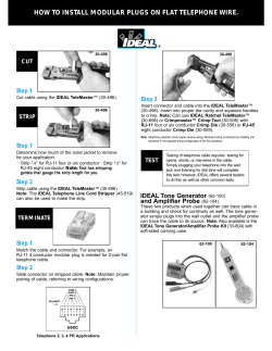

© Copyright 2026