
XP95 Intrinsically Safe (IS) Manual Call Point ®
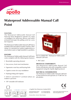
PP2457/2014/Issue 1
XP95® Intrinsically Safe (IS) Manual Call Point
FUNCTION
The XP95 IS addressable Manual Call Point has
been designed to operate as part of a radial
circuit in hazardous areas when connected to a
protocol translator and galvanic barrier.
An alarm is initiated by pressing the resettable
element. The Manual Call Point signals to
the Control and Indicating Equipment using
an interrupt feature within the Apollo Digital
Protocol. An alarm status is indicated by a
tellow and black bar in the lower section
of the resettable element and a red LED.
The Manual Call Point can be easily reset from
the front using the supplied reset key
The XP95 IS Manual Call Point can be used for
both indoor and outdoor applications and has
a IP67 rating.
FEATURES
This product offers:
•
ATEX Approved
•
Resettable operating element
•
Easy access, front reset mechanism
•
Ergonomic reset key and keyring hole
•
EN5 4 -11 Approved ( Red version only)
Part no 55200-940 - XP95 IS Manual Call Point
•
IP67 rating
•170° viewable LED
PROTOCOL & SYSTEM CAPABILITY
The XP95IS Manual Call Point is designed for
use only in an intrinsically safe system together
with a protocol translator and a safety barrier*.
Details of system design can be found in
Engineering Product Guide PP1095.
The protocol translator (part no. 55000– 855
single channel, 55000–856 dual channel), whilst
remaining transparent to the control panel,
ensures the call point operates correctly.
*Apollo recommends the Galvanic
Barrier (part number 29600-098)
© Apollo Fire Detectors Limited 2014
36 Brookside Road, Havant,
Hampshire, PO9 1JR, UK.
MANAGEMENT
SYSTEMS
Assessed to ISO 9001:2008
LPCB Cert No. 010
Tel: +44 (0)23 9249 2412
Fax: +44 (0)23 9249 2754
MANAGEMENT
SYSTEMS
Certificate No. 010
See www.RedBookLive.com
Assessed to ISO 14001:2004
Certificate number EMS 010
Overseas offices: America China Germany
0359
1180
Email: [email protected]
Web: www.apollo-fire.co.uk
The XP95 IS Manual Call Point will operate only
with control equipment using the Apollo XP95
digital protocol.
TECHNICAL DATA
ELECTRICAL CONSIDERATION
The XP95 IS Manual Call Point is loop powered
and operates at 14-22V DC.
Communications Protocol XP95 5 - 9V Peak to Peak
MECHANICAL CONSTRUCTION
The component parts of the call point are
moulded in a robust fire retardant polycarbonate.
OPERATING PRINCIPLES
The address of each call point is set at the
commissioning stage by means of a sevensegment DIL switch.
Supply voltage Operating temperature
14-22V DC
-20°C to +60°C (T4)
-20°C to +40°C (T5)
Humidity (no condensation or icing)
IP rating
Quiescent
230µA
Alarm Load (LED On)
Once activated, the XP95 IS Manual Call Point
can be reset by inserting the reset key into the
front facing LED turning clockwise until a positive
click and reset is present.
Certified to ATEX Directive 94/9/EC
Certificate number BAS02ATEX1290X
A copy of the Declaration of Conformity is
available from Apollo on request.
Conformity of the Manual Call Point with the
EMC Directive does not confer compliance
with the directive on any apparatus or systems
connected to it.
67
Current Consumption (max) at 22V DC
A red alarm LED is provided on the call point.
This LED is controlled independently of the call
point, by the control panel.
EMC DIRECTIVE 2004/108/EC
The Manual Call Point complies with the essential
requirements of the EMC Directive 2004/108/EC,
provided that it is used as described in this data
sheet.
0-95%
Power Up Surge (1s typical)
1.2mA
1mA
Equipment Markings
II 1G Ex ia IIC T5 Ga (-20°C ≤ Ta ≤+45°C)
or Ex ia IIC T4 Ga (-20°C ≤ Ta ≤+60°C) or
II 1D Ex ia IIIC T135°C Da (-20°C ≤ Ta ≤
+60 °C)
Complies with EMC Directive 2004/108/EC
Red version complies with EN54–11:2001
DIMENSIONAL DRAWING
DIMENSIONS AND WEIGHT
Part no
Description
55200-940
XP95 IS Manual
Call Point
Dimension
& Weight
110mm x
x 74mm
330g
Figure 1 Typical Response Characteristics - XP95 IS
Manual Call Point
110mm


© Copyright 2026