
RENEWABLE ENERGY DEVELOPERS’ MANUAL Ukraine Sustainable Energy Lending Facility
Ukraine Sustainable Energy Lending Facility (USELF) RENEWABLE ENERGY DEVELOPERS’ MANUAL Kiev 2014 USELF_EN_Fin.indd 1 13.06.2014 12:08:48 USELF_EN_Fin.indd 2 13.06.2014 12:08:48 Foreword This Developers’ Manual has been prepared as part of the technical assistance programme under the Ukraine Sustainable Energy Lending Facility (USELF). USELF has been established and is financed by the European Bank for Reconstruction and Development (EBRD) with additional backing from the Clean Technology Fund (CTF). Technical assistance is provided under a grant from the Global Environmental Facility and coordinated by the EBRD. The Manual is produced in both Ukrainian and English for distribution primarily to interested Ukrainian developers and investors but also among international developers interested in investment in the renewable energy sector in Ukraine. The Manual has a twofold approach. First, it is intended as a help to developers to better understand the process for submitting an application, the project screening process and the due diligence appraisal that their project has to undergo before qualifying for USELF financing. Secondly, and with a broader perspective, it will provide potential developers with information about how to improve the preparation and development of renewable energy projects employing different technologies, irrespective of USELF funding, and also for the time after termination of the USELF facility. This includes the considerations and steps that are recommended by the developer for project implementation under the aspects of: • technical development and planning of the project, procurement of equipment and implementation arrangements • legal and regulatory requirements in the energy sector as well as prerequisites for permitting and licensing • arrangements for financing under “project finance schemes”, which means financing on the basis of standalone project companies with non-recourse or limited recourse financing • appraisal of financial viability of projects • requirements for environmental and social assessment. It is the strong desire of the authors that, with this Manual, we can put a tool in the hands of developers so they can prepare technologically sound RE projects which have been prudently analyzed for their financial viability, to pass swiftly through the jungle of the permitting and licensing process, and to comply with all environmental and social standards or, in other words, that allows them to implement their projects successfully with a minimum of risks and friction. I USELF_EN_Fin.indd 1 13.06.2014 12:08:48 After a short description of USELF and the USELF Project Cycle, the Manual presents the development and implementation process for the various renewable energy technologies from planning, engineering and procurement perspectives. This is followed by chapters on the legal and regulatory framework and the financial framework for project development, the latter focusing in particular on non-recourse and limited recourse project financing. Finally environmental and social aspects for developing renewable energy projects are addressed. II USELF_EN_Fin.indd 2 13.06.2014 12:08:48 Table of Contents 1. Introduction to USELF������������������������������������������������������������������������������������������������������������ 1 2. USELF Project Cycle Requirements������������������������������������������������������������������������������������ 2 2.1 Overview���������������������������������������������������������������������������������������������������������������������������������������� 2 2.2 Application and General Eligibility���������������������������������������������������������������������������������� 3 2.3 Preliminary Screening and Mandate Letter����������������������������������������������������������������� 4 2.4 Due Diligence: Why, How, and What?����������������������������������������������������������������������������� 6 2.6 Project Implementation and Monitoring���������������������������������������������������������������������� 9 3 RES-E Technologies����������������������������������������������������������������������������������������������������������������10 3.1 Wind Power Plants�����������������������������������������������������������������������������������������������������������������10 3.1.1 General��������������������������������������������������������������������������������������������������������������������������������10 3.1.2 Technology aspects�������������������������������������������������������������������������������������������������������10 3.1.2.1 Energy source��������������������������������������������������������������������������������������������������������������10 3.1.2.2 Technology overview�����������������������������������������������������������������������������������������������11 3.1.2.3 Energy yield������������������������������������������������������������������������������������������������������������������13 3.1.2.4 Design and performance data�������������������������������������������������������������������������������14 3.1.2.5 Cost indicators�������������������������������������������������������������������������������������������������������������16 3.1.3 Development and implementation of wind projects������������������������������������17 3.1.3.1 Critical factors for success�������������������������������������������������������������������������������������17 3.1.3.2 Overview of project steps �������������������������������������������������������������������������������������19 3.1.3.3 Pre-feasibility study��������������������������������������������������������������������������������������������������20 3.1.3.4 Feasibility study and design���������������������������������������������������������������������������������22 3.1.3.5 Procurement – EPC-turnkey contract vs multi-lot contract������������������24 3.1.3.6 Construction�����������������������������������������������������������������������������������������������������������������25 3.1.3.7 Commissioning�����������������������������������������������������������������������������������������������������������26 3.1.3.8 Operation������������������������������������������������������������������������������������������������������������������������26 3.2 Photovoltaic Power Plants��������������������������������������������������������������������������������������������������27 3.2.1 General��������������������������������������������������������������������������������������������������������������������������������27 3.2.2 Technology aspects�������������������������������������������������������������������������������������������������������28 3.2.2.1 Energy source��������������������������������������������������������������������������������������������������������������28 3.2.2.2 Technology overview�����������������������������������������������������������������������������������������������29 III USELF_EN_Fin.indd 3 13.06.2014 12:08:48 3.2.2.3 Energy yield������������������������������������������������������������������������������������������������������������������30 3.2.2.4 Design and performance data�������������������������������������������������������������������������������31 3.2.2.5 Cost indicators�������������������������������������������������������������������������������������������������������������32 3.2.3 Development and implementation of PV projects�����������������������������������������33 3.2.3.1 Critical factors for success�������������������������������������������������������������������������������������33 3.2.3.2 Overview of project steps���������������������������������������������������������������������������������������34 3.2.3.3 Pre-feasibility study��������������������������������������������������������������������������������������������������35 3.2.3.4 Feasibility study���������������������������������������������������������������������������������������������������������35 3.2.3.5 Tender design���������������������������������������������������������������������������������������������������������������36 3.2.3.6 Construction�����������������������������������������������������������������������������������������������������������������36 3.2.3.7 Commissioning�����������������������������������������������������������������������������������������������������������36 3.2.3.8 Operation������������������������������������������������������������������������������������������������������������������������37 3.2.3.9 EPC turnkey contract vs multi-lot contract �������������������������������������������������37 3.3 Small Hydropower Plants (SHPP)�����������������������������������������������������������������������������������39 3.3.1 General��������������������������������������������������������������������������������������������������������������������������������39 3.3.2 Technology aspects�������������������������������������������������������������������������������������������������������39 3.3.2.1 Energy source��������������������������������������������������������������������������������������������������������������39 3.3.2.2 Technology overview�����������������������������������������������������������������������������������������������40 3.3.2.3 Design and performance data�������������������������������������������������������������������������������49 3.3.2.4 Energy yield������������������������������������������������������������������������������������������������������������������53 3.3.2.5 Cost in\dicators������������������������������������������������������������������������������������������������������������53 3.3.3 Development and implementation of SHPP projects�����������������������������������56 3.3.3.1 Critical factors for success�������������������������������������������������������������������������������������56 3.3.3.2 Overview of project steps���������������������������������������������������������������������������������������58 3.3.3.3 Pre-feasibility study��������������������������������������������������������������������������������������������������59 3.3.3.4 Feasibility study ��������������������������������������������������������������������������������������������������������60 3.3.3.5 Design������������������������������������������������������������������������������������������������������������������������������61 3.3.3.6 Procurement ����������������������������������������������������������������������������������������������������������������61 3.3.3.7 Construction�����������������������������������������������������������������������������������������������������������������62 3.3.3.8 Commissioning�����������������������������������������������������������������������������������������������������������63 3.3.3.9 Operation������������������������������������������������������������������������������������������������������������������������63 3.4 Biomass and Biogas Plants�������������������������������������������������������������������������������������������������64 IV USELF_EN_Fin.indd 4 13.06.2014 12:08:48 3.4.1 General��������������������������������������������������������������������������������������������������������������������������������64 3.4.2 Technology aspects – biomass��������������������������������������������������������������������������������66 3.4.2.1 Energy source – raw materials����������������������������������������������������������������������������67 3.4.2.2 Technology overview�����������������������������������������������������������������������������������������������68 3.4.2.2.1 Biomass receiving and processing�����������������������������������������������������������������69 3.4.2.2.2 Energy conversion and power production��������������������������������������������������70 3.4.2.2.3 Flue gas cleaning and emissions��������������������������������������������������������������������76 3.4.2.2.4 Solid residues�����������������������������������������������������������������������������������������������������������76 3.4.2.2.5 Water����������������������������������������������������������������������������������������������������������������������������77 3.4.2.3 Energy yield������������������������������������������������������������������������������������������������������������������77 3.4.2.4 Design and performance data�������������������������������������������������������������������������������78 3.4.2.5 Cost indicators�������������������������������������������������������������������������������������������������������������79 3.4.2.5.1 CAPEX��������������������������������������������������������������������������������������������������������������������������79 3.4.2.5.2 O&M costs�����������������������������������������������������������������������������������������������������������������80 3.4.3 Development and implementation of biomass projects�����������������������������81 3.4.3.1 Critical factors for success�������������������������������������������������������������������������������������81 3.4.3.2 Overview of project steps���������������������������������������������������������������������������������������82 3.4.3.3 Pre-feasibility study��������������������������������������������������������������������������������������������������83 3.4.3.4 Feasibility study���������������������������������������������������������������������������������������������������������84 3.4.3.5 Design �����������������������������������������������������������������������������������������������������������������������������86 3.4.3.6 Optional: tendering���������������������������������������������������������������������������������������������������87 3.4.3.7 Construction�����������������������������������������������������������������������������������������������������������������87 3.4.3.8 Commissioning�����������������������������������������������������������������������������������������������������������88 3.4.3.9 Operation������������������������������������������������������������������������������������������������������������������������88 3.4.4 Technology aspects – biogas������������������������������������������������������������������������������������88 3.4.4.1 Energy source – feedstock�������������������������������������������������������������������������������������89 3.4.4.2 Biogas production technologies and technical components�����������������92 3.4.4.2.1 Receiving, storage, and pre-treatment of feedstock������������������������������94 3.4.4.2.2 Anaerobic digestion�����������������������������������������������������������������������������������������������95 3.4.4.2.3 Process stability���������������������������������������������������������������������������������������������������100 3.4.4.2.4 Process control������������������������������������������������������������������������������������������������������101 3.4.4.2.5 Digestate������������������������������������������������������������������������������������������������������������������102 V USELF_EN_Fin.indd 5 13.06.2014 12:08:49 3.4.4.3 Biogas yield����������������������������������������������������������������������������������������������������������������103 3.4.4.4 Energy production��������������������������������������������������������������������������������������������������104 3.4.4.5 Energy yield���������������������������������������������������������������������������������������������������������������106 3.4.4.6 Design and performance data����������������������������������������������������������������������������106 3.4.4.7 Cost indicators ���������������������������������������������������������������������������������������������������������107 3.4.4.7.1 CAPEX�����������������������������������������������������������������������������������������������������������������������107 3.4.4.7.2 O&M costs��������������������������������������������������������������������������������������������������������������108 3.4.5.1 Critical factors for success����������������������������������������������������������������������������������109 3.4.5.2 Overview of project steps������������������������������������������������������������������������������������109 3.4.5.3 Pre-feasibility study�����������������������������������������������������������������������������������������������111 3.4.5.4 Feasibility study������������������������������������������������������������������������������������������������������112 3.4.5.5 Design ��������������������������������������������������������������������������������������������������������������������������114 3.4.5.6 Optional: tendering������������������������������������������������������������������������������������������������114 3.4.5.7 Construction��������������������������������������������������������������������������������������������������������������115 3.4.5.8 Commissioning��������������������������������������������������������������������������������������������������������115 3.4.5.9 Operation���������������������������������������������������������������������������������������������������������������������116 3.4.6 Technology aspects – landfill gas (LFG)-to-energy �����������������������������������116 3.4.6.1 Energy source�����������������������������������������������������������������������������������������������������������117 3.4.6.2 Technology overview��������������������������������������������������������������������������������������������121 3.4.6.2.1 Landfill gas collection���������������������������������������������������������������������������������������122 3.4.6.2.2 Energy production����������������������������������������������������������������������������������������������124 3.4.6.3 Energy yield���������������������������������������������������������������������������������������������������������������126 3.4.6.4 Design and performance data����������������������������������������������������������������������������126 3.4.6.5 Cost indicators����������������������������������������������������������������������������������������������������������127 3.4.6.5.1 CAPEX�����������������������������������������������������������������������������������������������������������������������127 3.4.6.5.2 O&M costs��������������������������������������������������������������������������������������������������������������128 3.4.7 Development and implementation of landfill gas (LFG)-to-energy projects���������������������������������������������������������������������������������128 3.4.7.1 Critical factors for success����������������������������������������������������������������������������������128 3.4.7.2 Overview of project steps������������������������������������������������������������������������������������129 3.4.7.3 Pre-feasibility study�����������������������������������������������������������������������������������������������130 3.4.7.4 Feasibility study������������������������������������������������������������������������������������������������������131 3.4.7.5 Design���������������������������������������������������������������������������������������������������������������������������132 VI USELF_EN_Fin.indd 6 13.06.2014 12:08:49 3.4.7.6 Optional: tendering������������������������������������������������������������������������������������������������132 3.4.7.7 Construction��������������������������������������������������������������������������������������������������������������133 3.4.7.8 Commissioning��������������������������������������������������������������������������������������������������������133 3.4.7.9 Operation���������������������������������������������������������������������������������������������������������������������134 4. Legal and Regulatory Framework���������������������������������������������������������������������������������� 135 4.1 General Overview of the RES Regulatory Framework ��������������������������������������135 4.2 Permitting and Licensing Process�������������������������������������������������������������������������������140 4.2.1 Main stages of RES plant construction������������������������������������������������������������140 4.2.2 Land allocation �����������������������������������������������������������������������������������������������������������141 4.2.3 Grid connection ����������������������������������������������������������������������������������������������������������145 4.2.4 Construction and commissioning�����������������������������������������������������������������������147 4.2.5 Licenses and permits for RES plant operation���������������������������������������������149 5. Financial Framework���������������������������������������������������������������������������������������������������������� 151 5.1 General Considerations Regarding Funding Renewable Energy Projects��������������������������������������������������������������������������151 5.2 Project Finance and Its Implications��������������������������������������������������������������������������154 5.2.1 Characteristics of project finance������������������������������������������������������������������������154 5.2.2 Main phases and key players involved������������������������������������������������������������155 5.3 Factors Influencing Renewable Energy Financing����������������������������������������������158 5.4 Financial Analysis: Methods, Indicators, Sensitivity Analysis������������������������160 5.4.1 Purpose and general approach�����������������������������������������������������������������������������160 5.4.2 Financial indicators���������������������������������������������������������������������������������������������������163 5.4.3 Sensitivity analysis����������������������������������������������������������������������������������������������������166 5.5 Risk Management����������������������������������������������������������������������������������������������������������������169 5.5.1 Characteristics of risk management������������������������������������������������������������������169 5.5.2 Identification of risks������������������������������������������������������������������������������������������������169 5.5.3 Risk assessment and mitigation��������������������������������������������������������������������������171 6. Environmental and Social Considerations������������������������������������������������������������������� 173 6.1 Key Environmental and Social Impacts of Different Types of Renewables �������������������������������������������������������������173 6.1.1 Project siting considerations �������������������������������������������������������������������������������173 6.2 General Construction Impacts���������������������������������������������������������������������������������������173 6.3 Operation Impacts of Different Renewable Technologies �������������������������������174 VII USELF_EN_Fin.indd 7 13.06.2014 12:08:49 6.3.1 Windfarms����������������������������������������������������������������������������������������������������������������������174 6.3.2 Solar photovoltaic�������������������������������������������������������������������������������������������������������174 6.3.3 Small hydropower������������������������������������������������������������������������������������������������������175 6.3.4 Biogas ������������������������������������������������������������������������������������������������������������������������������177 6.3.5 Biomass���������������������������������������������������������������������������������������������������������������������������177 6.4 Social Impacts and Cultural Heritage������������������������������������������������������������������������177 6.5 National Environmental Requirements �������������������������������������������������������������������178 6.5.1 General overview of key applicable environmental laws and regulations�����������������������������������������������������������������178 6.5.2 Regulations for environmental impact assessment and review����������179 6.5.3 Ukrainian public consultation and disclosure requirements����������������181 6.5.4 Environmental permits for project operation�����������������������������������������������182 6.5.5 Implementation of national requirements�����������������������������������������������������182 6.6.1 Overview of EBRD requirements������������������������������������������������������������������������183 6.6.2 Performance requirements�������������������������������������������������������������������������������������185 6.7 Implementation of the EBRD Requirements����������������������������������������������������������187 6.7.1 Developer’s steps to meet the requirements ������������������������������������������������187 6.7.2 Environmental and Social Action Plan (ESAP)��������������������������������������������188 6.7.3 Stakeholder Engagement Plan (SEP)����������������������������������������������������������������188 6.7.4 Non-Technical Summary (NTS) �������������������������������������������������������������������������189 6.7.5 Organizational capacity and commitment of the developer������������������190 6.8 Further Information about Environmental, Social, and Health Requirements ��������������������������������������������������������������������������������190 Case Study: Porogy Solar Power Plant��������������������������������������������������������������������������������� 193 Case Study: Ivankiv Biomass Power Plant Project����������������������������������������������������������� 196 Case Study: Ecoprod Agricultural Company����������������������������������������������������������������������� 199 VIII USELF_EN_Fin.indd 8 13.06.2014 12:08:49 Abbreviations AC Alternating Current ARC Autonomic Republic of Crimea BAT Best Available Technology BOD Biological Oxygen Demand BOP Balance of Plant BoQ Bill of Quantity CAD Computer-Aided Design CAPEX Capital expenditures CCI Architectural and Construction Control (in Ukraine) COD Chemical Oxygen Demand DC Direct Current DNI Direct Normal Irradiation DS Dry Solid DSCR Debt Service Coverage Ratio EIA Environmental Impact Assessment E&M Electrical & Machinery EP Equator Principle EPC Engineering, Procurement, Construction ESAP Environmental and Social Action Plan ESIA Environmental and Social Assessment ESHA European Small Hydropower Association ESMP Environmental and Social Management Plan FDC Flow Duration Curve FS Feasibility Study GRP Glassfibre Reinforced Plastic HSE Health, Safety and Environment IEA International Energy Agency IEC International Electrotechnical Commission ILO International Labour Office IRR Internal Rate of Return kW Kilowatt IX USELF_EN_Fin.indd 9 13.06.2014 12:08:49 kWh Kilowatt-hour LFG Landfill Gas LLCR Loan Life Coverage Ratio LOI Letter of Intent LV Low Voltage MV Medium Voltage MW Megawatt MWh Megawatt-hour NERC National Electricity Regulatory Commission NPV Net Present Value NTS Non-Technical Summary OPEX Operation expenditures ORC Organic Ranking Cycle PC Project Company PPA Power Purchase Agreement PR Performance Requirements (requirements of EBRD) PR Performance Ratio (for PV plants) PV Photo Voltaic RES Renewable Energy Sources RfP Request for Proposal RoR Run of River SCADA Supervisory Control and Data Acquisition SEP Stakeholder Engagement Plan SHPP Small Hydropower Plant SPV Special Purpose Vehicle TEO Feasibility Study (in accordance with Ukrainian legal requirements) TOC Total Organic Carbon UES Unified Electricity System VAT Value Added Tax VS Volatile Solid WHO World Health Organization WEM Wholesale Electricity Market X USELF_EN_Fin.indd 10 13.06.2014 12:08:49 1. Introduction to USELF The Ukraine Sustainable Energy Lending Facility (USELF) is an investment facility established by the European Bank for Reconstruction and Development (EBRD) for fostering renewable energy projects in Ukraine. The Facility comprises a loan volume of €70 million, to which the EBRD contributes €50 million, while the Clean Technology Fund (CTF) provides a further €20 million. USELF is structured to provide financing directly from the EBRD for small and medium projects with a simplified and rapid approval process, so reducing transaction costs. In addition to debt finance, the Facility provides development support to projects meeting commercial, technical, and environmental eligibility criteria. Target projects include all forms of power generation from renewable energy sources, including hydro, wind, biomass, biogas, and solar. Biomass and input for biogas production would come from sustainable sources and/or organic waste. Production and distribution of liquid biofuels are not eligible. Companies applying for a loan within USELF get a unique opportunity to receive attractive EBRD financing as well as technical assistance from international and local experts. Their advantages comprise: • loans starting from €1.5 million • reduced transaction costs • longer-term limited recourse finance • technical assistance free of charge. Investment projects are assessed by the EBRD on the basis of information made available by the developers, such as feasibility studies and business plans. Technical consultants undertake a project appraisal and submit to the EBRD a technical, environmental, and financial evaluation report of the prospective projects as well as provide advice on the permitting process to the companies. Interested developers are encouraged to contact the USELF team with their project idea. The USELF team will do a quick assessment of general project eligibility and then guide the developer through the application process and further project appraisal. USELF Developers’ Manual USELF_EN_Fin.indd 1 1 13.06.2014 12:08:49 2. USELF Project Cycle Requirements 2.1Overview Figure 2‑1 shows a flowchart of the various steps required for the implementation and appraisal of projects under the USELF framework, from the application questionnaire to actual implementation of the RE facility. The individual steps are then described in detail in the following sections. Preliminary technical screening Submission of the technical application questionnaire Mandate letter with EBRD Technical and environmental due diligence Decision on loan approval Project Implementation and monitoring Figure 2‑1: Sequence of USELF project implementation steps 2 USELF_EN_Fin.indd 2 Chapter 2: USELF Project Cycle Requirements 13.06.2014 12:08:49 2.2 Application and General Eligibility Once an interested company has put together sufficient information about the envisaged project that ensures that the project can constitute a sound investment and the developer is convinced that it can provide the necessary equity contribution of 40% of total project costs, the developer should fill out the Technical Application Questionnaire available from the USELF website and submit it to the USELF team by e-mail, mail, or fax. In addition, information about the financial and commercial status of the developer and its affiliated companies as well as about potential co-financiers need to be provided. On the basis on this information, the USELF advisors first check the general eligibility of the developer and the project. The advisors may request additional information from the developer in order to fill information gaps or to substantiate certain facts and figures. Eligibility In order to qualify for a USELF loan, the companies and projects have to meet certain institutional, financial, and technical eligibility criteria. General eligibility criteria for companies Eligible companies are: • privately owned, registered and operating in Ukraine • operating in compliance with national environmental, health, and safety legislation • not engaged in activities prohibited under the EBRD’s Exclusion and Referrals list (tobacco, alcohol, etc.). Further, companies applying for financing under the Facility must meet the following eligibility criteria, not all of which need necessarily be confirmed upfront but might be assessed in the course of further analysis: • for existing businesses: proven track record and sound credit history, including financial reporting according to local accounting standards • startup energy projects are judged on the basis of the customary technical and market due diligence, as well as satisfactory financial projections • good reputation and corporate governance practices, including satisfactory results under the Bank’s integrity due diligence procedure USELF Developers’ Manual USELF_EN_Fin.indd 3 3 13.06.2014 12:08:50 • willingness to introduce International Financial Reporting Standards (IFRS) reporting (if not already in place) within a reasonable timeframe from signing the loan agreements (up to two years) • sound management and organizational structure • sound financial structure (including sufficient security package for proposed borrowing) • compliance with the Bank’s procurement and environmental requirements. Eligibility criteria for projects Eligible projects should: • replace electricity generated from conventional energy sources • be based on proven technology • be financially viable • provide greenhouse gas emission reductions. Projects must also comply with applicable EBRD, national, and European Union requirements for health and safety, and especially, but not restricted to the Habitat Directive, for the impacts of certain public and private projects on the environment. These criteria are assessed at a later stage of the appraisal process, but the developer must already be aware of them when applying at the Facility. 2.3 Preliminary Screening and Mandate Letter Upon confirmation of the general eligibility of the developer’s company and the project, the preliminary screening process is started by the USELF team. To this end, the team sends an additional list of information required and questionnaires, depending on what information has already initially been provided by the developer together with the application questionnaire. The screening exercise at this stage puts particular emphasis on the ownership structure of the project and the project company in order to identify the ultimate beneficiaries of the project and on the financial strength of the investors (developer and potential co-investors). As this also uses information already provided by the developer in the very beginning, assessment of the eligibility (section 2.2) transits fluently into preliminary screening in this regard. Equal emphasis is put on assessing the process for obtaining the necessary permits, licenses, etc. This is of high importance at this stage, as inaccurate steps 4 USELF_EN_Fin.indd 4 Chapter 2: USELF Project Cycle Requirements 13.06.2014 12:08:50 taken by the developer to this end that are possibly not absolutely in line with the legal and regulatory requirements might ultimately lead to a delay in project implementation or even bring the project to a complete stop. At the same time, the screening exercise comprises the technical side of the project, the chosen technology, the equipment to be used for the project, and the overall implementation arrangements. This is done at a comparatively high level, while a detailed assessment in this field follows during the due diligence phase. However, there are some differences in the level of detail, depending on the type of renewable energy. While the technology in the case of wind and PV solar projects is comparatively uniform, it is much more diverse and site-specific for biogas and biomass projects, and in particular, for hydropower projects. Therefore, these types of technologies must be analyzed in a bit more detail than the former ones. During the preliminary screening, an analysis of the financial viability is also made. This is based on the preliminary cost estimates for CAPEX and OPEX, the preliminary technical key parameters (output, full load operation, initial energy yield assessment results in the case of solar and wind projects, etc.) and a set of macroeconomic parameters and financing conditions. The financial analysis is complemented by a sensitivity analysis that checks the robustness of the financial results against changes in the values of key parameters. Finally, the preliminary screening also comprises a first round of environmental and social assessment. While this is usually quite a high-level exercise at this stage, the ultimate level of depths of the analysis depends on which documents are already available at this time (e.g. is a local Environmental Impact Assessment - OVOS already available or not?). As a result of the preliminary screening process, a report, the Preliminary Screening Report (PSR), is prepared by the advisors and submitted to the EBRD. Upon receipt of this PSR, the Bank initiates its internal first round of approval process (Concept Review), which leads to the Concept Review Memorandum (CRM), an internal appraisal and approval document. If the CRM leads to positive results and the project proposal is approved by the EBRD in principle, subject to further detailed due diligence, a Mandate Letter is issued by the EBRD. This Mandate Letter is sent to the Developer and is then signed by the Developer and the EBRD. The Mandate Letter is a short document of only a few pages that, in essence, stipulates that the Bank is willing to provide finance for the screened project, USELF Developers’ Manual USELF_EN_Fin.indd 5 5 13.06.2014 12:08:50 subject to satisfactory results of the detailed due diligence process and negotiations between the Bank and the Developer, and that the Developer is willing to accept the loan from the Bank. The Mandate Letter lays down the loan amount that EBRD and CTF will provide for financing the project, envisaged pricing of the loan (interest rate and fees), repayment schedule, maturity and grace period. It also includes provisions regarding a nominal fee to be paid by the Developer as well as a break-up fee, which has to be paid by the Developer if he stops pursuing financing of the proposed project, which is also nominal. 2.4 Due Diligence: Why, How, and What? Due diligence is a term for which there are several technical definitions depending on the circumstances. However, in the context of this manual, due diligence simply refers to the exercise of reasonable care prior to committing to any business venture. This must be a detailed study of all aspects of the business. A due diligence or business review is an essential step in evaluating a target business or new business venture. The objective of a due diligence or business review is to provide a coherent and focused review to help evaluate the target business or new business venture and to identify negotiation issues. The aim of the review is to enhance the Bank’s understanding of the business, its critical success factors, and its strengths and weaknesses, thus highlighting potential problems and opportunities and providing information about key issues that need to be addressed both before and after completion and settlement of any transaction. So the concept is really all about the diligence that is due when investigating an emerging company’s plan for doing business. The developer or the project company make some form of disclosure within the business plan and/or other documents provided, but the responsibility further examining and verifying the statements made in that document falls squarely on the shoulders of the lender. For the scope of the developer’s financing experiences, he should always assume that the potential funding source is the one that will check and recheck everything presented by the entrepreneur; in the case of USELF, this is done through the advisor. Although due diligence can be performed on all aspects of a business, the main ones are as follows: • due diligence on the borrower/investor • technical due diligence 6 USELF_EN_Fin.indd 6 Chapter 2: USELF Project Cycle Requirements 13.06.2014 12:08:50 • contractual/legal due diligence • financial due diligence • environmental due diligence. Due diligence on the borrower/investor Ownership is an important issue in the process. It is necessary for the Bank to understand the business background as well as the financial status and strength of the developer and his possible co-financiers. While this has already been checked during the initial assessment and the preliminary screening process, it is updated and summarized during the due diligence phase. The Project Company (Special Purpose Vehicle) that implements the project is also assessed and its ultimate beneficiaries is identified and appraised. Finally, a very important aspect for the Bank is the integrity check of the developer and owner, which demonstrates that they meet the requirements included in the integrity checklist of the Bank. Technical due diligence This concerns a review of the technology to be used and involves questions such as ‘Is the technology a proven technology or innovative?’ and ‘What risks are connected to the use of that technology?’ Usually, specific technical reports and/ or feasibility studies have been made and all assumptions and conclusions concerning the general technical concept, processes, and equipment are scrutinized during the due diligence process. It also deals with the assessment of the expected energy generation of the envisaged project. The technical due diligence also reviews the arrangements for engineering, procurement, and project implementation, including the reasonableness of the implementation schedule. At the same time, the arrangements for operating and maintaining the RE plant are assessed. Contractual and legal due diligence Contractual rights and obligations, licenses, and permits are also investigated thoroughly. Studies underlying the project are reviewed as well as the assumptions that were made. An aspect of particular importance is the land use arrangements, as the project requires a sound land lease agreement with an appropriate leasing term (usually 25 years) or land ownership as its basis, while at the same time, the land’s designated purpose must be suitable for erecting the power plant. Further aspects that are reviewed include the Detailed Plan of the Territory, the procedure for its development, and related land issues. USELF Developers’ Manual USELF_EN_Fin.indd 7 7 13.06.2014 12:08:50 Contractual due diligence also comprises grid connections, which covers the status of both the grid connection requirements and the grid connection agreement. The licenses and contracts required in connection with the off-take arrangement are briefly addressed, but as these documents are finalized only after the plant has been commissioned, a detailed assessment does not take place at this stage. Financial due diligence The financial viability of the project and the financial situation of the project company that is to implement a project are very important issues. The financial due diligence must, therefore, show that the project is financially viable such that it leads to satisfactory Net Present Values (NPV) and Internal Rates of Return. The debt situation, profitability, and cash flow analysis of the project company are essential ingredients in the due diligence process. As the developers do not usually use uniform templates and models for their own financial analysis and often prepare only very cursory viability and liquidity calculations, the financial due diligence of the proposed projects is carried out with a financial model developed by the advisor specifically for USELF due diligence, which guarantees the application of the same framework of assumptions for all projects and, thus, uniform treatment of all applications. Financial due diligence also comprises sensitivity analyses that allow the robustness of the financial analysis to be checked in the case of changes to key parameters. Environmental and social due diligence Environmental and social aspects are an important element of any lender. The environmental impact of a project or business needs to be carefully studied, but equally important is the assessment of the envisaged mitigation measures. The conclusions and assumptions of the study or studies are part of the due diligence process. Environmental due diligence also assesses the Environmental and Social Action Plan (EAP) and Stakeholder Engagement Plan (SEP) if these documents are already available. Otherwise, the Consultant provides the developer with advice about preparing these documents. Environmental due diligence also analyzes the level of reduction in Greenhouse Gas Emissions, which is an important aspect for the Bank. The results of the various aspects of due diligence are presented in a due diligence report, called a Project Appraisal Note (PAN), which are prepared by the Advisor and submitted to the EBRD . 8 USELF_EN_Fin.indd 8 Chapter 2: USELF Project Cycle Requirements 13.06.2014 12:08:50 2.5 Loan Approval Upon receiving the PAN, the Bank continues to assess the proposed project and initiate the steps for a final review and, ultimately, loan approval if the final review leads to findings that are satisfactory to the Bank. This is done for the structured review process and leads to the Final Review Memorandum, an internal approval document of the Bank. Approval of the final review results and other loan documents allows the loan agreement to be signed. 2.6 Project Implementation and Monitoring Once the loan agreement is signed, the project implementation stage is the final stage. This includes constructing the RE facility and its subsequent operation. The Bank and its advisor monitor and supervise the construction process, but also the operation phase. This ensures that project objectives are achieved and that problems in the implementation/construction process can be recognized in time, so that they can be solved efficiently with no lasting harm for the project. To this end, the developer needs to submit reports to the Bank that provide information about the project implementation and its progress, together with information about factors that could possibly negatively affect project implementation. The reporting intervals are laid down in the loan agreement. The advisors provide support to developers during the implementation process. USELF Developers’ Manual USELF_EN_Fin.indd 9 9 13.06.2014 12:08:50 3 RES-E Technologies 3.1 Wind Power Plants 3.1.1General The wind resources in Ukraine, coupled with the existing transmission infrastructure and load requirements, are sufficient to allow development of significant wind power facilities in Ukraine. Onshore windfarms are attractive thanks to their rapid capacity expansion and high technical availability. Additionally, the latest generation of wind turbines with large rotor diameters and greater hub heights can harvest the wind potential of previously unexploited locations even if wind conditions are less favorable. However, planning a windfarm project must take into account a number of factors which need to be considered, such as: • proper measurement and determination of the wind resource and resulting energy yield • site suitability, including good site accessibility, minimum distances to settlements, and low environmental impact • selection of suitable equipment • contracting and interface coordination • construction management • operation concept. The following sections outline the way to plan the above aspects thoroughly together with the related costs, thus ensuring a successful wind project. 3.1.2 Technology aspects 3.1.2.1 Energy source The terms wind energy and wind power refer to the process of harvesting the kinetic energy from the wind and converting it into mechanical power and then into electric power by means of wind energy converters (wind turbines). The origin of the energy in the wind is the sun. Uneven heating of the earth by the sun creates pressure differences across the earth’s surface, causing the wind 10 USELF_EN_Fin.indd 10 Chapter 3: RES-E Technologies 13.06.2014 12:08:50 to move from high-pressure to low-pressure regions. The equator, for example, receives more solar radiation than the poles, resulting in a higher temperature and, therefore, rising air. Rotation of the earth and seasonal variation in the incoming energy from the sun also play an important role in defining global winds. Added to these theoretically smooth global winds is the effect of the earth’s surface due to varying land masses and water, inland water bodies, topographic variation, and the surface cover of the earth, which all affect local winds with all their variations and turbulences, especially within the troposphere, where the wind energy is actually harvested. Once a suitable site for a wind project has been identified, it is of utmost importance that suitable wind data are available for the location. If there is an existing wind project within 4-10 km of the windfarm, it can be verified whether the production data of this project are sufficient. If not, a separate wind measurement at the location has to be performed. Taking multiple measurements at the windfarm location is very important for obtaining reliable results within the wind study, which identify: • reference wind speeds and wind direction • surface roughness and wind shear • extreme wind conditions • standard deviation and turbulence intensity • climatic conditions, including temperature and humidity. These results again influence the selection of a suitable wind turbine generator and the layout of the windfarm. 3.1.2.2 Technology overview Wind turbines have developed from their ancestors – wind mills – which have been used by humans for thousands of years. They mostly consist of a rotor placed in the wind flow rotating a shaft, where the mechanical energy can be taken for direct use or for further conversion to electric energy. Electricity-producing wind turbines are considered in this report. Different concepts have been applied throughout the years to harvest wind energy, some of which have fallen out of favor while others have advanced to be a part of the modern range of wind turbines. For example, devices that use lift force with USELF Developers’ Manual USELF_EN_Fin.indd 11 11 13.06.2014 12:08:50 the help of airfoils in the form of blades have been favored on drag machines, using the drag force of the wind against a surface, due to their higher levels of efficiency. Modern wind turbines are generally horizontal axis machines with three blades mounted on the hub rotating a main shaft, which drives an electric generator either directly or through a gearbox. The gearbox, generator, and auxiliary equipment are housed in a nacelle at the top of the tower. A yaw mechanism turns the nacelle and the rotor into the direction of the wind. A typical horizontal wind energy converter consists of: • the rotor, which in turn, consists of a hub and rotor blades which convert the energy in the wind into rotational shaft energy • a drive train, usually including a main shaft, bearings, gearbox, and generator or, in the case of gearless wind turbine design, only a generator • the nacelle containing the drive train, yaw mechanism, and cooling • the tower that supports the rotor and drive train • the foundation • other equipment, including controls, electric cables, ground support equipment, and interconnection equipment. Figure 3‑1: Typical wind turbine schematic 12 USELF_EN_Fin.indd 12 Chapter 3: RES-E Technologies 13.06.2014 12:08:51 3.1.2.3 Energy yield The amount of available kinetic energy in the wind depends on the speed of movement and the total mass. The mass per unit of time depends on the density of the matter, the area in question, and again, the speed of movement through this area. Available wind power is, therefore, the kinetic power of the wind going through the area of the rotor of the wind turbine: where: • m is the mass in [kg] and the mass flow in [kg/s] • v is the wind speed in [m/s] • A is the area of the rotor in [m2] • ρ is the density of air in [kg/m3]. From the formula, it can be seen that the extractable wind power strongly depends on the wind speed, increasing with its third power, and linearly on the area of the rotor and the air density. The total available wind power that can be extracted by a wind turbine is limited though by the theoretical maximum of 59.3%, known as the Betz limit. From the practical aspect, the energy yield also depends on the design of the wind turbine, i.e. the aerodynamic design of the rotor blades, the control algorithms steering the wind turbine, and its design limits (cut-in and cut-out wind speed, gusts, etc.). Over the last two decades, wind turbines converting the kinetic energy of the wind to electricity have developed into automated power plants with increasing rotor areas and hub heights and also with a high power quality to conform to the electric grids’ requirements. However, the amount of energy produced at any one time depends on the wind conditions. USELF Developers’ Manual USELF_EN_Fin.indd 13 13 13.06.2014 12:08:51 For typical projects to be economically viable, the minimum annual average wind speed at 80 m (hub height) should be more than 5.0 to 5.25 m/s, and a good site will have more than 6.0 m/s. 3.1.2.4 Design and performance data Power curve There are various possibilities for the aerodynamic control of rotor speed and power. These are usually mainly used to limit the maximum power extracted from the wind to keep operation within the design limits for the loads and power of the different wind turbine components. This maximum power produced is referred to as the rated power, and the wind speed at which this power is first reached is called the rated wind speed. The cutout wind speed is the speed at which the turbine shuts down to protect itself from high loads (typically 25 m/s). Cut-in wind speed is the minimum speed at which the turbine starts producing power and feeding it to the grid. In between, the relation between the power produced and the wind speed at hub height for each wind turbine model is described by the power curve. 3000 kW Wind Turbine Power Output 2500 kW 2000 kW 1500 kW 1000 kW 500 kW 0 kW 0 5 10 15 20 25 Wind Speed in m/s Figure 3‑2: Exemplary power curves of different wind turbines of the 2 MW class 14 USELF_EN_Fin.indd 14 Chapter 3: RES-E Technologies 13.06.2014 12:08:51 In the above figure, the differences between the different wind turbine models regarding their efficiencies become evident. The blue power curve already produces more energy at lower wind speeds and is, therefore, also suitable for lower average wind speeds. The power curve of each wind turbine model is provided by the manufacturer and is the basis for calculating the wind energy assessment. Usually, the power curve was obtained through certified measurements according to the industry standard IEC 61400-12. However, if the wind turbine is a very new development, only a calculated power curve may be provided by the manufacturer, although this has greater uncertainties related to the electrical output. Structural design of a wind turbine The design and performance criteria for a wind turbine location are closely related to each other and mainly refer to the wind characteristic at the location. The stronger the wind at the location, the better the energy yield; however, the structural resistance of the wind turbine must also be stronger. According to IEC 61400-1, a wind energy site is associated to different “wind turbine generator system classes” based on site-specific wind data, such as the expected mean wind speed at hub height, the turbulence intensity, and extreme wind speeds. Table 3‑1 provides the corresponding values of extreme and average wind speeds for associating sites with turbine classes. WTGS class I II III IV Reference wind speed vref [m/s] 50 42.5 37.5 30 Annual average wind speed vave [m/s] 10 8.5 7.5 6 50-year return gust speed 70 59.5 52.5 42 1-year return gust speed 52.5 44.6 39.4 31.5 Turbulence intensity I15, class A 18% Turbulence intensity I15, class B 16% Table 3‑1: Assignment of turbines according to site conditions (IEC 61400-1) USELF Developers’ Manual USELF_EN_Fin.indd 15 15 13.06.2014 12:08:51 Wind turbines are designed according to the aforementioned standard and for the use at locations with the respective wind characteristics for a design lifetime of 20 years. The manufacturers prove this design to a certification body (DNV, GL, TÜV, etc.) and, if it also complies with series manufacturing, obtain a type certificate for the entire wind turbine and its components configuration. If the manufacturer maintains that a wind turbine of a specific IEC class is suitable at a location with stronger winds (e.g. a class IIIB wind turbine at an IIB location), he must provide the relevant calculation and proof. 3.1.2.5 Cost indicators CAPEX The economics of owning a wind turbine depend on many factors, including wind speeds, the size and cost of the turbine, interest rates, taxes, and electricity prices. The following concerns onshore windfarms. Windfarm capital expenditures (CAPEX) can be divided in two main parts: • development costs: land, wind turbines, grid, permits • equipment and construction costs: wind turbines and required infrastructure (substation, cabling, roads, crane platforms). The typical costs for the manufacturing, transport, and installation of a wind turbine farm are approximately €1,300 –2,000 per kW installed (or US$1,700–2,600 per kW), depending on the size, the transport outlay, and the amount of work required for grid connection. The following Figure 3‑3 illustrates the major shares of the investment costs of a typical windfarm project. 100% Grid connection 11% Foundation 16% Wind Turbines 64% Turbine Cost Distribution Planning & Miscellaneous 9% 90% 80% 70% 60% 50% 40% Generator Transformer Power Converter Gearbox Rotor Blades Tower 30% 20% 10% Other 0% Source: IRENA, Renewable Energy Technologies: Cost Analysis Series Figure 3‑3: Typical cost breakdown of onshore wind projects 16 USELF_EN_Fin.indd 16 Chapter 3: RES-E Technologies 13.06.2014 12:08:51 OPEX Besides CAPEX, operational expenditures (OPEX) of a windfarm project constitute a main share of the costs of a wind energy project. These can be crucial for the economic viability of a project, so they must be forecast meticulously. These costs arise after a project is commissioned and continue throughout its lifetime, and they comprise: • maintenance service (periodically scheduled maintenance, unscheduled maintenance and repair works, spare parts, cleaning of blades, and others) • land lease (if applicable) • project insurance • operation monitoring (SCADA, on site) • administration, taxes, etc. OPEX typically account for 1.5–2.5% of the investment costs per year (or 20–30% of the total levelized cost of energy of a wind project). In any case, all estimations agree that: • Cost increases as the project lifetime increases. • Modern wind turbines have lower O&M costs than older ones. • There is an economy of scale: decreasing specific O&M costs with increasing project size. 3.1.3 Development and implementation of wind projects 3.1.3.1Critical factors for success Site selection Selecting a suitable location for a windfarm is essential for a successful and economically viable project. This, though, may be governed by many factors that influence this process. The main considerations when selecting a location are: • Initial assessment of wind conditions through generally available data at or near the potential location. Although this is could be far from calculating correct and reliable results, it can provide a first idea of how potentially favorable a location is. • General site assessment, including topography and existing obstacles such as buildings or forest and their potential influence on both the productivity and the cost of the project. USELF Developers’ Manual USELF_EN_Fin.indd 17 17 13.06.2014 12:08:51 • Accessibility of the location with existing access roads and their condition and distances from the potential site, considering the sizes of the components and the quality requirements of the necessary roads. • Availability of a grid connection point for the planned windfarm and the strength of this grid in relationship to the planned capacity and costs of an additionally needed electricity network in coordination with the grid operator and relevant legislation. • Soil quality and associated work for foundation design, construction, and costs, and their impact on the feasibility of the windfarm. • Consideration of residential areas and infrastructure, and the potential impact of the windfarm on these: shadow, noise, visibility, microwave data links, radar interference, airports, etc. Wind measurement A wind measurement must be taken for at least a full year to cover all seasonal influences. To record appropriate and reliable data, the measurement setup, location, and height of the measurement mast must comply with established international standards, and at least with both of the following: • IEC 61400-12-1 • MEASNET recommendations. The sensors must be calibrated and in areas with low temperature. In winter, heated anemometers should be used. The basic components of every measurement system comprise: • data logger • anemometers (at least 2 different heights) • wind vane(s) at each measurement height • hygro-thermal sensor • barometric pressure sensor • power supply (usually solar panels). Additional optional components are: • GSM/GPRS data transfer system • precipitation sensor • obstacle lights. 18 USELF_EN_Fin.indd 18 Chapter 3: RES-E Technologies 13.06.2014 12:08:51 On-site wind conditions must be correlated with a long-term measurement, not necessarily at the same location, to estimate extreme wind conditions and correct the measured on-site wind speeds. As for all types of renewable energies, a structured and complete documentation of all planning steps and results is required and considered a general success factor. 3.1.3.2 Overview of project steps 1 Pre-Feasibility 2 Feasibility • Preliminary analysis of potential sites with respect to general suitability and expected irradiation (on basis of available satellite data) • Initial generation forecast • Preliminary EIA • Preliminary layout and BoP • Land securing 3 Tender Design • Detailed irradiation evaluation • Technology selection • Analysis of PV technologies • Conceptual design • Optimization of technical concept • Generation forecast • Technical specification and interface coordination • CAPEX, OPEX and Cashflow • General layout • EIA • MV cabling • (Preliminary) Geotechnical investigations • Grid connection design 1-2 months • O&M concept 2 - 3 months 4 Procurement 5 Construction 2-3 months 6 Commissioning 7 Operation • Request for quotation • Detailed design review • Mechanical completion • 2-year EPC warranty period • Pre-tender site visit (s) • Construction of • O&M contract • Preparation of quotations • cable trenches • roads • foundations • mounting structure • substation • Installation of • Commissioning of DC and AC electrical infrastructure • Trial operation • Independent inspections • Finalization of civil works • Final Acceptance after 2 years • Review • Negotiation • Award of contract • PV modules • Provisional Acceptance Test • Insurances • Definition of punch list items • Cables • Inverters and transformers 2-3 months Signed 4-12 months Contracts 1-2 months About 20 years Figure 3‑4: Overview of project steps for wind power plants USELF Developers’ Manual USELF_EN_Fin.indd 19 19 13.06.2014 12:08:52 3.1.3.3 Pre-feasibility study A preliminary study aims to determine if it would be worthwhile to proceed to the feasibility study stage. In terms of wind power plants, the focal points of a pre-feasibility study are: • site selection • preliminary wind potential analysis • identification of suitable areas • preliminary EIA • site assessment • preliminary layout and balance of plant (other infrastructure). Site selection The main objective of a site selection program is to identify potentially windy areas that also possess other desirable qualities of a wind energy development site. For a project developer, this may concern only the land areas that are at his disposal or if he is screening a region or the municipality comprises a larger area. The site selection can be carried out in two steps. The first step involves identifying potential sites for wind energy use considering wind resources at height hub, while the second step involves exclusion criteria, which determine whether a location may or may not be suitable for operating WECs. This process screens a relatively large region (e.g. district, state, or utility service territory) for suitable wind resource areas based on information such as wind resource maps, satellite wind data, reference wind time series airport wind data, topography, and other indicators. In determining potential sites, all land that may not be suitable for windfarm development is deducted from the identified suitable wind resource areas. The following exclusion criteria are typical criteria used in selecting a windfarm site: • settlement areas • residential areas • industrial and commercial sites • hamlets, farms, or individual houses • infrastructure areas subject to a building ban • transport infrastructure 20 USELF_EN_Fin.indd 20 Chapter 3: RES-E Technologies 13.06.2014 12:08:52 • overhead lines • airports • mining areas • nature and landscape • national parks • national natural monuments • biosphere reserves • conservation reserves • legally protected biotopes • natural monuments • water conservation areas • water bodies. The point at which a suitable wind resource area intersects with an area considered infeasible for windfarm development indicates an area of potential wind development. Site assessment During the site assessment, the potentially suitable areas are investigated in more detail with regard to technical and planning (environmental and land use) aspects: • topography of the site • location of obstructions • grid connection to the transmission system • maximum installed capacity • accessibility to the site • land ownership • distance to settlements • environmental constraints • location of visually sensitive viewpoints • cellular phone service reliability for data transfers • constraints associated with communications signals such as microwave link corridors, if any. If possible, site visits should be conducted for all potentially suitable areas with the main goal of verifying site conditions. Based on the available land and the topography, a first windfarm layout and balance of plant can be developed. The site assessment results in a ranking of candidate sites. USELF Developers’ Manual USELF_EN_Fin.indd 21 21 13.06.2014 12:08:52 3.1.3.4 Feasibility study and design Feasibility study The feasibility study further details the results of the pre-feasibility study and comprises all results required for: • the permitting procedure • the investors and financing of the project. One of the most important aspects to be detailed during the feasibility study is the windfarm layout. Wind turbines can be installed alone or as part of a windfarm, which can include hundreds of wind turbines. Choosing the location of each of these turbines influences the energy production and efficiency of the complete farm, the layout of access roads and electric cabling within the windfarm, and the loads on other wind turbines on the farm. When choosing these locations, the following aspects must be considered: • minimizing the influence of wake effects from turbines on those behind them in relation to the wind direction and, therefore, keeping certain minimum distances between turbines, also in relation to prevailing wind directions • minimizing turbulence on individual turbines not only from the wake of other turbines but also from obstacles and the topography of the land • optimal windfarm electrical interconnection and further connection to the grid to minimize electric losses and costs • available access roads or roads that may have to be built and their costs • soil properties and foundation stability • ownership of the land and land lease contracts • distances to overhead lines. The feasibility study should at least address the following topics: • project background • project organization • legal framework • technical concept and layout • location and infrastructure • land ownership • windfarm layout • civil works • electrical works 22 USELF_EN_Fin.indd 22 Chapter 3: RES-E Technologies 13.06.2014 12:08:52 • grid connection • environmental impacts and mitigation measures • energy yield assessment • permitting status • procurement concept • construction work program • time schedule • cost estimate • financial analysis • risk analysis. The contents of the feasibility study are input for the feasibility study required according to Ukrainian legislation for obtaining the building permit. The contents must be coordinated accordingly. Conceptual design In addition to the feasibility study, which describes the background information and the assumptions made, the conceptual design is prepared in parallel. The conceptual design consists of CAD drawings, layout plans, and electrical single line diagrams, and it serves as: • the basis for the cost estimate assumptions (mass balances) • the tendering of the civil and electrical works. For the preparation of the conceptual design, it is recommended that the potential future wind turbine manufacturers are already involved and provide information about their requirements during the construction (access road and crane platform specifications, electrical requirements, etc.). If several wind turbine manufacturers remain in competition, the layout and infrastructure must fulfill the requirements of all competitors. It is recommended to obtain approval from the wind turbine manufacturer(s) that the planned layout is suitable. All components and parts of the equipment must be designed, manufactured, and installed in accordance with the applicable national norms and standards, and if no wind-specific norms and standards are available at a national level, international norms and standards shall apply. For wind turbine design, this is especially IEC 61 400 - 1 and all subsequent standards. USELF Developers’ Manual USELF_EN_Fin.indd 23 23 13.06.2014 12:08:52 3.1.3.5 Procurement – EPC-turnkey contract vs multi-lot contract Besides wind turbine supply and assembly, the main trades relating to wind energy projects are civil works for access roads, crane pads, foundation works, and the cabling system inside and outside the windfarm. For single-trade construction, the windfarm owner has two basic alternatives: • contract the different trades or lots to several independent companies, known as multi-contracting • contract to only one company (EPC contractor), which is responsible for the detailed planning, procuring the components, the construction, and the turn-key handover of the windfarm. Depending on the capacity, skill set, and resources of a project developer, the construction of smaller windfarms is usually coordinated by project developers themselves, contracting various qualified contractors within the scope of several requests for proposal (RfPs). With regard to the operating company, the project developer acts as an EPC contractor and hands over the turn-key windfarm. Where large windfarms and international windfarm development are concerned, turnkey project development is usually the rule. The wind turbine manufacturer often operates as the EPC contractor, constructing the complete windfarm and managing the interaction of different lots through the participation of subcontractors. This is mainly because the costs of the wind turbine constitute the major part (> 75–80%) of the total windfarm investment. For the project developer or windfarm owner, involving an EPC contractor generally has several advantages, such as minimal outlay for the contracting entity, all responsibility and interface coordination in the hands of one party, a fixed price, as well as favorable procurement alternatives due to contractual and organizational benefits. On the other hand, contracting a single EPC company can reduce the competition as not all wind turbine manufacturers offer EPC turnkey ser-vices. Furthermore, the quality must be specified very carefully to obtain the components and project realization that the developer expects. If an EPC contractor is commissioned to construct a turn-key windfarm, its experience in developing such projects is a major decision criterion. When an EPC contractor is commissioned, the windfarm owner relinquishes his freedom to choose the most efficient subcontractor for the different lots to achieve the lowest possible total investment costs. 24 USELF_EN_Fin.indd 24 Chapter 3: RES-E Technologies 13.06.2014 12:08:52 If multi-lot contracting is the preferred method of constructing the windfarm, the owner must possess (or buy in) good project management skills to handle multi-contracting with well-organized interface coordination and scheduling. Banks usually prefer EPC turnkey over multi-lot procurement concepts as they clearly allocate the risks during construction. Nevertheless, for each situation, it is necessary to consider the pros and cons of choosing an EPC turnkey contract or a multi-lot contract and develop with the respective organization. In many projects, the contractual agreements between the owner and the EPC contractor are based – especially in projects with international investors or banks – on the framework of the International Association of Engineers (FIDIC – Federation Internationale des Ingenieurs Conseils), the Conditions of Contract for EPC/ Turnkey Projects (“silver book”). 3.1.3.6 Construction Before the site construction can start, the contractors are required to submit their detailed design for approval. The detailed design must be reviewed by the developer with respect to its compliance with the following: • permit approval conditions • grid operator’s conditions • technical specification and functionality as per the contract (or proposal) • the appropriate interfaces with the other lots. Should the developer not have appropriately experienced staff, it is recommended that he awards a contract to an experienced technical advisor (“owner’s engineer”). It is also recommended that the owner’s engineer is present on the construction site during the most important construction and installation activities in order to verify the quality of the works and compliance with the permit approvals and contracts. During the construction, each contractor must report his progress on a regular basis (higher frequency at times of multiple on-site activities, e.g. weekly). The weekly progress report must contain a summary of the last few weeks’ completed works and the works planned for the next weeks, and it must include an updated time schedule. If several contractors are working on the construction site at the USELF Developers’ Manual USELF_EN_Fin.indd 25 25 13.06.2014 12:08:52 same time, a regular meeting between all contractors must be planned to coordinate the works and their timing. Health, safety, and environmental considerations and guidelines must have priority over compliance with the time schedule and work program, and they must be supervised by a relevant HSE coordinator. 3.1.3.7 Commissioning Several weeks of testing usually pass between the first kilowatt of electricity being produced and the wind turbine being handed over to the operator. The operator/operational manager of the wind turbine checks himself or arranges for an independent inspection to take place to verify whether the wind turbine is delivered and erected as agreed by contract and to ensure its proper and fault-free functioning. The common procedure is as follows: • mechanical completion of the installed components • test operation, surveyed by the manufacturer, and adjustment of parameters to the site-specific conditions • inspection and elimination of deficiencies by the manufacturer • acceptance inspection and handover to the operator or operational manager, which defines the start of the defect liability period. Once any initial problems (e.g. rotor imbalance) have been eliminated and the control parameters have been finally adjusted to the site conditions, the wind turbine is officially commissioned and handed over to the operator. An independent expert usually inspects the wind turbine for the operator to check and clarify whether all the specifications of the contract have been fulfilled. This inspection involves checking the technical condition of the wind turbine itself and its auxiliary installations, such as aviation safety markings or lights, a possibly modified power curve for reducing noise emissions, and so on. The requirements of the building permit are of prime importance in this context. 3.1.3.8Operation All major components of the wind turbines are expected to undergo routine maintenance. This would involve the use of small amounts of grease, lubricants, paints, and/or coatings for corrosion control. Waste resulting from component 26 USELF_EN_Fin.indd 26 Chapter 3: RES-E Technologies 13.06.2014 12:08:52 maintenance typically includes small amounts of gear oil and lubricating oils from yaw motors or of transmission and glycol-based coolants from transmissions equipped with forced-flow radiator cooling loops. Most turbine manufacturers design their turbines in modular fashion, which allows a single turbine to be down while remaining turbines continue to operate. Thus, it is likely that most major overhauls or repairs of turbine components would involve removing the component from the site to a designated off-site repair facility. Typically, if a generator or gearbox fails (sometimes, even if smaller components like yaw drives fail), a crane needs to be called to the site. Most turbines are not able to lift/lower those components on their own. The operation of a wind energy development project can be monitored and controlled from a remote location. For smaller sites, maintenance personnel may monitor the windfarm remotely and be on call for repairs. Only larger windfarms (>100 MW) will have a small full-time maintenance crew. The life of a wind turbine is expected to be 20–25 years with proper maintenance. As new technologies are developed over time, operators may choose to “repower” all or part of the site by replacing existing turbines with ones incorporating state-of-the-art technologies, or with larger and more cost-efficient turbines. Repowering may also involve replacing some electrical power management and conditioning equipment. 3.2 Photovoltaic Power Plants 3.2.1General In general, the production of electrical power through the transformation of solar radiation into energy can be achieved by the following technologies: • concentrating solar power (CSP) • concentrating photovoltaic (CPV) • non-concentrating photovoltaic (PV). The primary resource for CSP and CPV systems is direct solar irradiance. This is measured perpendicular to a surface that continuously tracks the sun (direct normal irradiation, or DNI). Deploying CSP and CPV requires a DNI of at least 1,800 kWh/m2 per year and 2,200 kWh/m2 per year respectively. Since the available DNI in Ukraine is, on average, approximately 1,300 kWh/m2 per year, CSP and USELF Developers’ Manual USELF_EN_Fin.indd 27 27 13.06.2014 12:08:53 CPV systems are usually not practicable. Concentrator systems are only competitive in a few regions on earth. However, for PV technology, the solar irradiation resources coupled with the existing transmission infrastructure and load requirements are sufficient to allow the development of significant PV power facilities in Ukraine. The planning of a PV plant project must take into account a number of factors, which need to be considered thoroughly, such as: • general suitability of the project site, including good accessibility and a minimum of external shading potential • detailed evaluation of the available irradiation levels • selection of the suitable equipment • design-compliant energy yield forecast • contracting and interface coordination • construction management • operation concept. The following sections outline the different aspects of PV technology together with the development steps for a sound PV project. 3.2.2 Technology aspects 3.2.2.1 Energy source The principle of photovoltaic (PV) is based on the photovoltaic effect, which transforms solar radiation energy directly into electrical energy. PV or solar cells are semiconductor devices that have the capability to convert sunlight into direct current (DC) electric energy. When the sunlight strikes a cell, a flow of electrons is generated proportional to the intensity of the sunlight and the area of the semiconductor cell. The solar energy is thereby transferred to the electrons in the semiconductor cell and, as a result, an electric voltage is generated. If a load is connected, an electric current flows. PV modules include one or more solar cell strings assembled as a pre-wired, field-installable unit. Since photovoltaic technology is characterized by its flexibility and modularity, the system designer has a high degree of freedom to obtain the required level of voltage and current of a PV module array by connecting the modules in series, parallel, or mixed configurations. Modules can be connected in series to obtain a higher system voltage or connected in parallel to obtain higher currents. To 28 USELF_EN_Fin.indd 28 Chapter 3: RES-E Technologies 13.06.2014 12:08:53 convert the DC output of the PV module array into alternating current (AC), solar inverters are used. They have special functions adapted for use with PV arrays, including maximum power point tracking and anti-islanding protection. Figure 3‑5: Basic concept of a PV plant 3.2.2.2 Technology overview The solar cells are the basic units of a PV system. Currently, two technologies dominate the market and can be classified as follows: • wafer-based crystalline silicon (c-Si) solar cells, which can be divided into: • monocrystalline cells (Mono c-Si) • polycrystalline cells (Poly c-Si) • thin-film cells, which, based on the materials used, can be divided into: • thin-film silicon/amorphous silicon cells (a-Si) • copper-indium/gallium-diselenide/disulfide solar cells (CIS, CIGS) • cadmium telluride solar cells (CdTe) • gallium arsenide solar cells (GaAs). Crystalline silicon (c-Si)-based modules have the largest share of PV modules on the world market. Efficiencies of crystalline modules range from 13% to up to 20%. Even though PV technology makes use of both direct and indirect solar radiation, higher energy yields can be generated by pointing the PV modules to the sun, along the path of the maximum achievable direct radiated power, when the solar radiation is perpendicular to the PV module surface. Depending on the location and economic aspects, different mounting concepts are applied and vary from fixed installations (see image above) to continuous single-axis horizontal and vertical tracking systems. Higher solar yields can be achieved by the latter. Usually, sin- USELF Developers’ Manual USELF_EN_Fin.indd 29 29 13.06.2014 12:08:53 gle-axis tracking systems are to be considered only for crystalline silicon (c-Si) PV modules. Figure 3 6: Polar and horizontal types of single-axis tracker1 3.2.2.3Energy yield For individual plant concepts, yield projections have to be performed considering typical (exemplary) plant components (PV modules, inverters, trackers) as well as the local meteorological conditions. For the yield projections, simulations need to be performed using the commercial and market standard software PVsyst, which provides the calculation for the two main results: 1. Annual total electricity generation (kWh/year) and annual specific electricity generation (kWh/kWp/year) The main steps in the simulation process are computations of: I) Incident energy: Global and diffuse irradiation data on the horizontal plane are used to calculate the irradiation on the tilted plane of the photovoltaic array (POA). The transposition of diffuse solar irradiation is carried out in the simulation process by means of specific models. II) Irradiation energy losses are computed by specific models representing optical, transmission, and/or surface effects to deliver the energy available for the irradiation-electrical conversion process. 1 http://www.solarchoice.net.au/index.php 30 USELF_EN_Fin.indd 30 Chapter 3: RES-E Technologies 13.06.2014 12:08:53 III) System performance is based on the properties and performance characteristics of PV modules (output power, partial shading effects, temperature behavior, etc.) and of the inverters (conversion efficiency, partial load, etc.). IV) Passive losses occurring in the electrical cabling are estimated to finally correct the energy delivered at the relevant energy meter. 2. Performance ratio (PR) The PR is the ratio (of annual values) of total AC energy to the theoretically available energy and gives an indication of the quality of the installation. The PR can be considered as the relationship between the effective and the theoretical (module operation at STC conditions) electricity production of a photovoltaic system measured at the relevant energy meter. The PR, there-fore, represents module performance that deviates from the standard conditions together with additional losses between the module and the relevant energy meter. The PR is related to the peak capacity and can be determined for any period of time. The performance ratio is usually calculated for a period of one year. 3.2.2.4 Design and performance data The design always deals with the assessment of technical alternatives. The main objective is to evaluate the suitability of PV technologies for constructing a PV plant in a specific region from a general perspective. The assessment compares possible technologies with respect to PV module technologies: • mono-crystalline • poly-crystalline • thin-film and with respect to the type of installation of the modules: • fixed installation • single-axis tracking • double-axis tracking. A thorough analysis of the general technology options is necessary in order to find the most suitable combination for the project environment. The outline of the key characteristics of the technologies as well as their ad-vantages and disadvantages with respect to the project under assessment comprises: USELF Developers’ Manual USELF_EN_Fin.indd 31 31 13.06.2014 12:08:53 • location of the site (external shading and space constraints) • row distance (internal shading) • string interconnection (effect of shading on DC output) • system design (sizing of inverters and MV equipment to avoid losses). Yield projections consider these plant specifications and, together with the (specific) electricity generation and the PR, provide the key figures for comparison on a technical basis. 3.2.2.5Cost indicators CAPEX The capital expenditures (CAPEX) of a PV plant can be broken down into the following: • development costs: land, grid, permits • financing costs: cost of funds, interest during construction • equipment and construction costs: PV modules, inverters, mounting system and required infrastructure (substation and cabling). However, the major driving factor behind capital expenditures is the cost of PV modules. In recent years, solar panel prices have represented approximately 50–60% of total PV system prices, depending on the market and application type. Module prices have been falling steadily for over a year and the share of the total system price decreased to about 40%. Crystalline technology has attained a major market share of more than 80%, so its prices are relatively well established and available on the spot market from different sources. In the case of thin-film, the prices can only be obtained publicly for CdTe and a-Si. Sale prices are not publicly available for CIS and CIGS. The spot market prices for modules are as follows (per Wp): • mono-Si • poly-Si • a-Si • CdTe • CIS €0.6–0.9 €0.6–0.9 €0.5–0.8 €0.6–0.8 €0.6–0.9 (estimated value). Capital expenditure for PV plants currently seen on the world market vary between €1,300/kWp and €1,800/kWp, depending on the region, technology (optionally including substation), and mounting system as described above. 32 USELF_EN_Fin.indd 32 Chapter 3: RES-E Technologies 13.06.2014 12:08:53 OPEX O&M activities are usually implemented via special-purpose contracts which cover power plant components, electrical infrastructure, and performing of preventive and corrective maintenance activities. The major cost component of the O&M costs is the staff. Typically, it can be assumed that, for a utility-scale PV power plant in the range of 5–10 MW, up to 12 people will be needed for operation, although most of these will be on a temporary basis. Operation and maintenance costs are substantially different for fixed and tracking systems. As indicative figures, O&M costs for fixed systems might be approximately €25–40/kWp, whereas tracking systems might be above €40/kWp. The O&M contracts must clearly define which kinds of services are included in the lump-sum price and which are not. Preventive (or scheduled) maintenance of the plant (and plant components) is usually included. All corrective maintenance is sometimes also included. In this case, the O&M contractor assumes the risk for component replacement if the component defect is not covered by a manufacturer guarantee. 3.2.3 Development and implementation of PV projects 3.2.3.1 Critical factors for success Site selection Selecting a suitable location for a PV plant is essential for a successful and economically viable project. This, though, may be governed by many factors that influence this process. The main considerations when selecting a location are as follows: • initial assessment of the solar resource in the form of global horizontal irradiation through generally available data at or near to the potential project location • site assessment, including terrain, topography, and existing obstacles such as buildings or trees and their potential influence on productivity due to shading • availability of water for the construction and operation phase • analysis of land use which has an impact on the land cost • accessibility of the location by existing access roads and their condition and distances from the potential site. Good road conditions are required to prevent mainly the inverters and PV modules from becoming damaged during shipment. • availability of a grid connection point for the planned PV plant and the strength of this grid in relationship to the planned capacity and costs of additional necessary electric network in coordination with the grid opera-tor and relevant legislation USELF Developers’ Manual USELF_EN_Fin.indd 33 33 13.06.2014 12:08:53 • seismic risk, groundwater, soil resistivity, pH levels, and load-bearing properties. The latter are particularly relevant in order to evaluate the type of possible foundations of the mounting system. • consideration of environmental and social sensitivity and potential effects of the PV plant such as visual impact, etc. 3.2.3.2Overview of project steps The following diagram shows the essential steps in project development, from the pre-feasibility study through to PV plant operation. 1 Pre-Feasibility 2 Feasibility • Preliminary analysis of potential sites with respect to general suitability and expected irradiation (on basis of available satellite data) • Initial generation forecast • Preliminary EIA • Preliminary layout and BoP • Land securing • DDetailed irradiation evaluation • Analysis of PV technologies • Optimization of technical concept • Generation forecast • CAPEX, OPEX and Cashflow • EIA • (Preliminary) Geotechnical investigations 1-2 months 4 Procurement • Request for quotation • Pre-tender site visit (s) • Preparation of quotations • Review • Negotiation • Award of contract 2-3 months Signed 3 Tender Design • Technology selection • Conceptual design • Technical specification and interface coordination • General layout • MV cabling • Grid connection design • O&M concept 2 - 3 months 5 Construction • Detailed design review • Construction of • cable trenches • roads • foundations • mounting structure • substation • Installation of • PV modules • Cables • Inverters and transformers 4-12 months 2-3 months 6 Commissioning 7 Operation • Mechanical completion • 2-year EPC warranty period • Commissioning of DC and AC electrical infrastructure • O&M contract • Trial operation • Independent inspections • Finalization of civil works • Final Acceptance after 2 years • Provisional Acceptance Test • Insurances • Definition of punch list items 1-2 months About 20 years Contracts Figure 3‑7: Overview of project steps 34 USELF_EN_Fin.indd 34 Chapter 3: RES-E Technologies 13.06.2014 12:08:54 3.2.3.3 Pre-feasibility study Within this first step of a potential project development, the decisive aspects for a realization are analyzed. This includes discussing the following topics: • project site and boundary area • permitting requirements • grid connection • preliminary design • approximate energy yield • outline of costs for development, construction, and operation of the project • estimation of the revenues. The analysis is based on indicative quotes and shows the character of a desktop study. A comparison with similar projects in the region is often undertaken. For grid connection and permitting, the likelihood of obtaining the necessary planning consent is rated. 3.2.3.4Feasibility study If the findings of the pre-feasibility study are positive, a feasibility study is conducted, which assesses the aforementioned topics in more detail. The aim of this study is to provide interested project parties and stakeholders with a reliable decision basis which enables the project to be further developed. Typically, the main objective is to create a basic design, which is needed as a baseline for all other associated development tasks. The design includes defining the plant orientation and tilt angles of the modules, assessing the shading (horizon and nearby objects), and specifying components such as the PV modules, inverters, mounting system, electrical and signal cabling, and the grid connection design. Based on the basic design, the following aspects can be discussed in more detail: • yield projection • cost estimation • requirements for grid connection • permitting application • financial modeling. USELF Developers’ Manual USELF_EN_Fin.indd 35 35 13.06.2014 12:08:54 3.2.3.5 Tender design The basic design of the feasibility study creates the necessary foundation for the detailed design that is usually engineered by the engineering, procurement, and construction (EPC) contractor within the bidding of the tendering process. Usually the bidding process is performed in a functional manner (functional specification of the conceptual design) so that the bidders have a certain degree of freedom to propose technical solutions they consider most suitable for a project in compliance with relevant standards. As a result, the outcome of the detailed engineering covers topics such as: • detailed design with civil and electrical layout • overall single line diagrams • MV and LV switchgear line diagrams • construction plans • project implementation schedule • testing and commissioning plans • adjusted yield projection. 3.2.3.6 Construction After the tendering and award of the EPC contractor, a PV plant is at the stage of construction that comprises the following main activities: • Procurement and transport of materials, components, and equipment. • Civil works are mainly characterized by activities related to preparing the terrain (leveling, compacting) and excavations for fundaments or cable trenches and the concreting of basements. • Mechanical works comprise tasks like embedding substructure piers/poles, assembling the metallic structures, and mounting PV modules. • Electrical works and instrumentation cover activities such as pulling LV and MV cables in trenches to electrical equipment (inverters, switchgears), installing electrical boxes and inverters with the corresponding electrical protection, and installing SCADA and security systems. 3.2.3.7 Commissioning Once the facility is completed in mechanical terms, a list of open items (punch list) is usually defined, which specifies activities to be performed by the EPC contractor prior to provisional and final acceptance of the PV plant. 36 USELF_EN_Fin.indd 36 Chapter 3: RES-E Technologies 13.06.2014 12:08:54 Once the construction activities have been completed, tests and trials of the electrical installations, components, and grid connection take place. Plant acceptance is carried out in two stages: • provisional acceptance • final acceptance. Both are defined in the EPC contract, including the related technical requirements, testing equipment, and measurement methods. The purpose of the provisional acceptance is to check the capacity and technical functionality of the plant and the minimum conditions to apply for the applicable feed-in tariffs regime, if any. It is carried out directly after works completion. 3.2.3.8 Operation The operation phase usually starts with taking over the PV plant (provisional acceptance) and, at the same time, the operation and maintenance (O&M) service is initiated. Although O&M and EPC contracts are to be kept legally separate from one another, the EPC contractor often also performs the O&M service. This has many advantages. For example, the EPC contractor usually has a more profound understanding of the characteristics and peculiarities of the plant which he himself has erected. Moreover, spare part issues can be handled more easily. Key elements of the O&M activities are: • preventive maintenance (regular services) • corrective maintenance (irregular repair services) • spare parts management • plant security • administration work • documentation/reporting on the operation status and plant performance. The final acceptance is usually certified after the plant has been in operation for 24 months. Its objective is to verify the performance and long-term energy production capability of the plant. 3.2.3.9EPC turnkey contract vs multi-lot contract EPC contracting for a PV plant can generally be divided into the following: USELF Developers’ Manual USELF_EN_Fin.indd 37 37 13.06.2014 12:08:54 • EPC turnkey contracting • multi-lot contracting. The turnkey approach has the advantage that the whole PV plant is constructed and installed in one operation. The EPC contractor is responsible for guaranteeing that the plant is erected on time and in a standardized manner and is, therefore, the sole point of contact for any claims in the event of contractual non-fulfillment. However, this is often associated with an increased EPC contract price. The EPC contract management and monitoring of the construction activities is also significantly less complex and extensive from a project developer’s perspective than that required for a multi-lot contract approach. The reason for this is that time and effort for interface management is passed from the project developer to the EPC contractor. However, a multi-lot contract approach has the advantage that the developer is given greater control over the final plant configuration. A turnkey EPC contract typically includes the following topics: • purpose of the EPC contract • tasks and duties of the client • scope of work of the EPC contractor • technical specifications • milestones and completion deadline • contract price and remuneration • acceptance • guarantees, liquidated damages, and bonds • insurance issues. For a multi-lot contract, the topics listed above must be covered for each lot separately, such as civil, mechanical, and electrical works. In general, a multi-lot contract approach might be applicable for an experienced project developer who can cover some of the lots through an available construction company of his own, for example, the civil works activities. However, other lots such as electrical works and instrumentation require the involvement of skilled (sub-)contractors who are familiar with the special requirements in the PV business sector. The overall responsibility for the complete PV plant must also be taken by a single entity in charge of the construction management and supervision. This 38 USELF_EN_Fin.indd 38 Chapter 3: RES-E Technologies 13.06.2014 12:08:54 ensures that the interfaces between the individual lots are properly addressed and reflected, which is especially important if underperformance or malfunctioning is detected after plant completion and financial compensation is required. 3.3 Small Hydropower Plants (SHPP) 3.3.1 General The utilization of hydropower started with the wooden waterwheel almost 2,000 years ago. In the first half of the 20th century, hydropower started to be exploited with the construction of dams and hydropower stations. It is, therefore, the first renewable source of energy used to produce electric power. Today, hydropower is the most common form of renewable energy and plays an important global role in electric power generation. In Europe, hydropower contributes almost 70% of the power generated by renewable energy sources. Considerations about the environmental impact of large-scale hydropower projects, the implementation of attractive policies favoring the supply of “green” electricity, and the key advantages of SHPP have boosted the small hydropower sector of industry. Although there is no strict definition of small hydropower, plants with installed capacities up to 10 MW are commonly considered as small hydropower plants (SHPP). This criterion is applied by ESHA (European Small Hydropower Association) and by IEA (International Energy Agency). The following sections outline how to plan an SHPP scheme thoroughly, together with the related costs. 3.3.2 Technology aspects 3.3.2.1 Energy source Hydropower is a renewable energy source based on the natural water cycle. A difference in water level is what drives the flow of water. This opportunity is available once a stream runs down a hillside, or a river passes over a waterfall or man-made weir, or where a reservoir discharges water back into the main river. Hence, a body of water possesses a given potential energy by virtue of its velocity and the vertical height through which it drops. The maximum available vertical distance between the upstream water level and the downstream water level is defined as the gross head (H). The available potential energy is dissipated by means of friction and turbulence. The net head is given by the gross head when the energy losses that occur during USELF Developers’ Manual USELF_EN_Fin.indd 39 39 13.06.2014 12:08:54 the conveyance of water through the power plant are subtracted. The head losses can be divided into minor and major losses. Minor losses usually occur at the trash rack, the inlet and the outlet, the bends of the conveyance structures, and the valves. The magnitude of these losses depends quadratically on the local flow velocity prevailing at these structures, i.e. a doubling of velocity leads to 4 times higher losses. Major losses occur due to friction along water conveyance structures and depend on their roughness and the flow velocity. Generally speaking, the smoother the boundary of the conveyance structure and the lower the flow velocity, the lower are the head losses. The flow of water causes the movement of appropriate machinery (“turbines”), which interrupts the field of flow. Consequently, the potential energy of the water is converted into mechanical energy. The rotation of the turbines forces the rotator of the generator to spin around the stator and so the mechanical energy is converted to electrical energy. Hence, there are two crucial factors controlling the available hydropower: The first is the difference between two water surface elevations, i.e. the head, and the second is the flow rate of the water, i.e. the volume of water passing per unit of time through a given surface. It is generally better to have more head than more flow, because this reduces the size of the equipment. On the other hand, the low head schemes are usually closer to the source of the power demand. 3.3.2.2 Technology overview The SHPP schemes are classified in the following categories: • depending on the hydraulic head available for utilization: • high head: H>100 m • medium head: 30m < H < 100 m • low head: H< 30 m • according to their operation: • run-of-river schemes • storage schemes. SHPP projects offer significant flexibility in their design. Possible sites for smallscale hydro schemes vary greatly. Areas with mountainous terrain and fast-flowing streams provide the necessary conditions for implementing high-head or medium-head SHPP schemes. Lowland areas with wide rivers provide feasible locations for installing low-head SHPP schemes. Most SHPPs are run-of-river plants, i.e. they generate electricity in accordance with the water availability in 40 USELF_EN_Fin.indd 40 Chapter 3: RES-E Technologies 13.06.2014 12:08:54 the river, which is subject to fluctuations due to the weather. Hence, they are not conceived to produce peak current, thus contributing only to the base load of the overall power system. Layout of SHPP schemes Depending on the site topography, different concepts can be applied to harvest hydropower. The four most common layouts for small hydro schemes are shown in the figure below. Figure 3‑8: Most common layouts for a small hydropower scheme USELF Developers’ Manual USELF_EN_Fin.indd 41 41 13.06.2014 12:08:54 • Medium-head and high-head SHPP schemes usually have a canal-penstock layout or a variation of it. The alignment of the canal follows the shape of the landscape. If the canal construction is difficult or can be completely avoided, the use of only a penstock is appropriate. In environmentally sensitive locations in particular, buried penstocks are the only acceptable solution in order to minimize the impact on the environment. Low-head SHPP schemes have two typical layouts: • The first layout is the scheme with a diversion canal. This can be used to gain more head by abbreviating a meandering river. Another advantage is the dry building pit while the diversion canal and the powerhouse are being erected. • The second layout is the erection of a barrage. Lower flow conditions can be compensated for by a reservoir. Additional head will also be gained by damming up the river. The powerhouse of this scheme is often integrated in the weir or dam structure. A chain of barrages is termed a cascade. Many rivers have been regulated in this manner. Main elements of SHPP schemes Depending on the available hydraulic head, the main components of an SHPP scheme are as follows: • Water intake structures that allow the abstraction of water from the river course and its diversion into a conduit system leading to the power plant. The following structures are usually considered: • A weir, i.e. an overflow structure built across an open channel that raises the upstream water level and/or measures the flow of water. This structure enables the water to be diverted to the water intake. Generally speaking, a weir imposes a manmade barrier to the natural river course, thus interrupting the transport of sediment and the migration of fishe and other aquatic organisms. Therefore, precautionary measures like flushing gates and fish passes should be implemented in order to mitigate these negative environmental impacts. • An intake, i.e. the structure that allows the entrance of water into the waterway structures under controlled conditions. It must be designed carefully to minimize the local head losses and preclude vorticity. A commonly implemented structure for diverting water from the water course, especially in mountain torrents, is the Tyrolean Weir. This consists of a submerged weir with an inclined trash rack, through which the required flow is diverted into the integrated water intake while the rest of the water continues to overflow it. The main advantages of this structure are that it is self-cleaning and does not interrupt the transport of pebbles and boulders. 42 USELF_EN_Fin.indd 42 Chapter 3: RES-E Technologies 13.06.2014 12:08:55 • Waterway structures comprise the scheme components that convey the water from the intake to the powerhouse. The waterway usually comprises some or all of the following structures: • A sandtrap, which ensures that undesired particles of certain sizes (e.g. grains larger than 0.2 mm) are removed and are, therefore, not transported to the turbine. The function of the sandtrap is based on the settling of undesired particles due to gravity in combination with a reduction of the flow velocity due to increased cross-section area. Next to the desander, a spillway is implemented to safely divert to an existing streambed or gully the back-flowing water if the slide gate shuts down suddenly. • A headrace, which safely conveys the water towards the forebay with minimum head losses. The headrace can be: • Open-channel with a rectangular or trapezoidal cross section. In the first case, the channel is made of concrete, while in the second, it can be designed as a stable earth channel. The flow velocity should be 1.0–1.5 m/s to avoid head losses and damage to the canal structure. The minimum freeboard for lined channels is about 10 cm, and for unlined channels, the freeboard should be about one third of the designed water depth with a minimum of 15 cm. • Tunnel, when the topographical circumstances do not allow the construction of an open channel. • A forebay that connects the headrace with the penstock. This provides some buffer in terms of sufficient volume of water for startup processes, thus preventing the entrainment of air into the penstock with the effect of an undesired collapse of the water column and associated pressure fluctuations. • A pressure pipe (or “penstock”) conveys the pressurized water from the forebay to the turbine. The penstock must be able to withstand the pressure rise caused by the “water hammer”, i.e. the pressure rise that occurs due to a rapid shutdown of turbines in the event of an emergency in addition to the pressure created by the static head. The penstock is always laid on a stable site, towards the hill slope, and is held by anchor blocks or, if necessary, supported by piers. Anchor blocks must be placed wherever the inclination or the direction of the penstock changes to enable the resulting forces to be handled safely. The penstock material can be steel or cast iron, plastic or glassfibre-reinforced plastic (GRP) pipes, pre-stressed concrete, reinforced concrete, or prestressed reinforced concrete. • A tailrace, i.e. a channel that discharges water from the powerhouse back into the river. The transition from the powerhouse to the river should be carried out in such a way that the water does not damage any structure or the landscape. USELF Developers’ Manual USELF_EN_Fin.indd 43 43 13.06.2014 12:08:55 • The powerhouse hosts the turbine together with the generator and the auxiliary equipment. The layout of the powerhouse should allow easy installation of the equipment as well as access for inspection and maintenance. The size of the powerhouse depends on the type and size of the installed equipment. The turbine and the generator are on the same shaft, which, in turn, can be horizontal or vertical. Implementing horizontal shafts leads to a cost reduction of approximately 20% for civil works due to the smaller height and easier installation of protection devices, such as flywheels. When the powerhouse is being designed, the installation of a crane for assembling generators, turbines, and other components should be taken into account. The capacity of the crane should be sufficient to move the heaviest part of the E&M equipment, ranging from 5 to 15 tons for SHPP schemes. • Hydraulic steel structures in an SHPP scheme include: • valves or gates, which are used to isolate one component from the rest, so they are either entirely closed or entirely open • distributor vanes or needle valves of the turbine used to regulate the flow • trash racks (or screens), which are nearly always required at the entrance of both pressure pipes and intakes to prevent floating debris from getting in. Turbine types Several turbine models have been developed over the years and are provided by the manufacturers. Each of these turbine models is better suited to a given constellation of hydraulic head and flow discharge. The main criteria for selecting the most suitable turbine are: • the principal site characteristics, namely, the available head and flow • the desired running speed of the generator • the variation of flow, e.g. if the turbine mostly operates in part-load conditions, which is the case when the discharge which is available throughout the year is mostly lower than the design discharge of the turbine. Turbines can be roughly classified as high-head, medium-head, or low-head machines. A further classification is based on their principle of operation, i.e. how the transformation of potential energy into rotational mechanical energy takes place. There are two main turbine types –reaction and impulse turbines – which are briefly described below. • Impulse turbines transform the kinetic energy of the flow into rotational mechanical energy when a jet from a nozzle hits the blades of the runner. Gen- 44 USELF_EN_Fin.indd 44 Chapter 3: RES-E Technologies 13.06.2014 12:08:55 erally speaking, impulse turbines are more efficient for high heads. The most commonly employed models of reaction turbines are the following: • The Pelton turbine is the most widespread model of this type and comprises a runner and one or more nozzles. The runner has blades shaped like a double spoon. Each nozzle has a movable needle to control the discharge. The maximum number of nozzles is two for a horizontal shaft and six for a vertical shaft. The nozzle has a deflector, which is a device to control the flow whenever a load rejection occurs, provoking a deflection of the jet and, thus, controlling the overpressure in the penstock and avoiding overspeed of the runner. Pelton turbines are not immersed in water but operate in air. • The Turgo turbine is based on the Pelton turbine, and it differs only in the angle at which the jet strikes the plane of the runner (about 20°). Therefore, the water can enter at one side of the runner and exit on the other, whereby the flow rate is not limited by the discharged fluid interfering with the incoming jet. Consequently, a Turgo turbine can have a smaller diameter runner than a Pelton for the equivalent power. • The crossflow (or Banki-Michell) turbine has a drum-like rotor with a solid disk at each end and gutter-shaped “slats” joining the two disks. As can be derived from the name of the turbine, the water passes transversely through the turbine. The water enters at the edge of the turbine and emerges on the opposite side, thus enabling additional energy to be generated. The main advantages of these turbines are as follows: • They can be easily adapted to fluctuating discharges with almost constant efficiency. • The avoidance of penstock overpressure and the control of runner overspeed are easier. • They are relatively easy to maintain. Pelton turbine1 Turgo turbine2 Crossflow turbine3 Figure 3‑9: Impulse turbines USELF Developers’ Manual USELF_EN_Fin.indd 45 45 13.06.2014 12:08:55 • Reaction turbines use the flow of water to generate hydrodynamic lift forces to propel the runner blades. The runner blades are profiled so that pressure differences across them impose lift forces that cause the runner to rotate. The rotor of this turbine type is fully immersed in water and is enclosed in a pressure casing. All reaction turbines have a diffuser known as a “draft tube” below the runner, through which the water discharges. The purpose of the draft tube is to decelerate the discharged water and to reduce the static pressure below the runner, thereby increasing the effective head. The most commonly employed models of reaction turbines are as follows: • The propeller turbine is an axial-flow turbine with a propeller-like runner that has three to six runner blades, depending on the design head. A key feature of this is that the water needs to be given some swirl before entering the turbine runner to ensure good efficiency. The inlet swirl is added by either using a set of guide vanes mounted upstream of the runner with water spiraling through them into the runner or by implementing a snail shell that houses the runner. The adjustable guide vanes allow the flow admitted to the runner to be varied. When the blades of the runner can also be adjusted, the turbine is called a Kaplan turbine. • In a Francis turbine, the water flows radially inwards around the runner and exits axially into the draft tube. The water is directed tangentially to the runner by means of a spiral case with guided vanes that surrounds the turbine. Propeller turbine4 Francis turbine5 Figure 3‑10: Reaction turbines Source: Verband der Elektrotechnik Source: BHA, Guide to UK mini-hydro development Source: ESHA, Guide on How to Develop an SHPP 5 Source: Electrical and Mechanical Services Department, Hong Kong 6 Source: Verband der Elektrotechnik 2 3 4 46 USELF_EN_Fin.indd 46 Chapter 3: RES-E Technologies 13.06.2014 12:08:55 Reaction turbines have the following advantages: • They need less installation space than impulse turbines. • They provide a greater net head and better protection against down-stream high flood levels as they can run submerged. • They have greater runner speed. • They can attain higher efficiencies for higher power values. The following table presents the commonly employed turbine models in SHPP schemes as well as their classification. Turbine type Impluse Head classification High (>50m) Medium (10-50m) Low (<10m) Pelton Turgo Multi-jet Pelton Crossflow Turgo Multi-jet Pelton Crossflow Francis (spiral case) Francis (open-flume) Propeller Kaplan Reaction Source: BHA, Guide to UK mini-hydro development Table 3‑2: Classification of commonly implemented turbine models The approximate ranges of heads, flows, and power applicable to the different turbine types are summarized in the chart below. These are approximate and depend on the precise design of each manufacturer. Generators In normal practice, only three-phase alternating current generators are used, the type of which is determined according to the characteristics of the network to be supplied. The planer must choose between synchronous and asynchronous generators. The synchronous generators are equipped with a DC electric or a permanent magnet excitation system associated with a voltage regulator that controls the output voltage before the generator is connected to the grid. In addition, excitation by synchronous generators is not grid-dependent and, hence, generators of this type can produce power even if they are not connected to the grid. In contrast, asynchronous generators are not able to regulate the voltage output and run at a speed which is related to the system frequency. Furthermore, they cannot produce power when they are isolated from the grid because they draw their excitation current from the grid. USELF Developers’ Manual USELF_EN_Fin.indd 47 47 13.06.2014 12:08:55 1000 00 500 10 50 10 00 kW 00 kW 50 Pelton 0 0 kW kW 300 200 Turgo Heagd in m 100 Francis 10 0 kW 50 50 30 kW 20 10 10 kW Banki-Mithell Kaplan 5 3 2 0 0,2 0,5 1 2 3 4 5 6 7 8 9 10 20 30 50 100 Discharge in m/seg Source: ESHA, Guide on How to Develop a SHPP Figure 3‑11: Head-flow ranges of small hydro turbines For systems below 1 MW, synchronous generators are more expensive than asynchronous generators. Their main advantage is that the voltage output is regulated and so they can be used in power systems where the output of the generator represents a substantial proportion of the power system load. On the other hand, asynchronous generators, which are a more economical option, are employed in the case of stable grids when the output of the SHPP scheme is insignificant compared to the power system load. Asynchronous generators are generally used as a cheap solution in very small stand-alone applications when the required quality of the electricity supply is not very high, while synchronous generators are installed when the power exceeds several MVA. Recent developments in the area of generators for SHPP schemes have provided solutions like the variable-speed constant-frequency systems (VSG), which might improve the system performance and reduce the costs, depending on the employed turbine type. 48 USELF_EN_Fin.indd 48 Chapter 3: RES-E Technologies 13.06.2014 12:08:56 Grid connection At the beginning of a project, it is important to know who will buy the produced power and whether the generated electricity will be used near the location of generation or whether it needs to be transmitted to regions with higher power demand. The electricity can be exported via the local distribution network by agreement with the distribution network operator (DNO) or, in some cases, distribution company. In that case, there should be early discussions with the DNO, who will specify the system protection and metering equipment. Furthermore, the DNO will provide an estimate of connection costs and the best location for feeding into their system. 3.3.2.3 Design and performance data Small hydropower plant projects must be planned and developed in accordance with prevailing natural conditions while also considering the possible environmental and social impact that may be triggered by their implementation and operation. Therefore, the basic data requirements for the design and implementation of an SHPP cover the following fields: • Topography of the project area: This outlines the boundary conditions and especially the available head. It is, therefore, imperative for the design of the SHPP. The accuracy of data should increase with each development step of the project, e.g. between pre-feasibility and feasibility. The topographic data is usually provided in the following form: • topographic map with a certain scale (e.g. 1:500) • digital elevation model. • Hydrology: Besides the hydraulic head, the possible discharge at the intake is the most important parameter for the design of an SHPP. A water authority usually measures the discharge in the most significant rivers and streams, so the corresponding discharge data can be obtained from the authority. The discharge at the site of the water intake is not normally available unless a measuring gauge is installed there. The data of an existing gauging station must, therefore, be transposed to the discharge characteristics at the location of the SHPP. For this purpose, the measurement records of the closest gauging station along the same river or, if this is not possible, the records of a gauge in a nearby area are usually used. The discharges provided should cover a time period of at least 15 years. If possible, these should be consecutive to allow statistically substantiated conclusions to be derived. To determine the stream flow at the location of the water intake, one of the following methods is applied: USELF Developers’ Manual USELF_EN_Fin.indd 49 49 13.06.2014 12:08:56 • Method 1: Simultaneous flow measurements This method provides the highest level of accuracy if applied appropriately. A temporary gauging point, the “control profile”, is implemented at an appropriate place, i.e. at the location of the future intake, usually upstream of the existing gauging station. Conducting simultaneous measurements ensures that the same weather conditions exist at both locations. Thus, the records of the gauging station can be correlated to the measurements at the water intake location. • Method 2: Specific run-off/altitude relationship This method is based on the development of an empirical functional relationship between the specific run-off (l/s/km²) and the average altitude of the catchment area. The underlying idea is that an increase in the altitude within the same catchment area is associated with an in-crease in run-off per unit area. • Method 3: Catchment area method This method assumes that the specific run-off remains the same throughout the catchment area. Thus, the intake discharge is a function of the catchment area. This method is a simple approximation which works sufficiently when the gauging station is close to the intake location. Based on one of the methods described above, the annual hydrograph is plotted, i.e. the day-by-day flow variation over a calendar year. The flow duration curve (FDC) can be easily derived from the annual hydrograph. The FDC shows how flow is distributed over a finite time period (usually a year). The flow records from a river gauging station that cover a time period of one year provide 365 daily mean discharge measurements. Based on these values, the frequencies of occurrence in selected discharge classes (groups) are compiled, starting with the highest values. The cumulative frequencies converted into percentages of the total number of days then form the basis for the FDC. The vertical axis specifies the flow, and the horizontal axis specifies the percentage of the year for which the flow equals or exceeds the value on the y-axis. Hence, the FDC can immediately indicate, for instance, the flow that will be available for at least 50% of the year (known as Q50). • Geology: To properly design the foundations of the civil structures to be implemented, it is necessary to obtain geological data in as much detail as possible. • First estimates of the predominant rock type could be made with the help of geological maps, probably available at a country level. • These initial estimates are of indicative nature and should be supplemented with further investigations (e.g. geological mappings), during which a rather detailed geological map of the project area is set up. 50 USELF_EN_Fin.indd 50 Chapter 3: RES-E Technologies 13.06.2014 12:08:56 • Prior to advanced planning, e.g. during the feasibility stage, geological surveys must be conducted with a subsequent laboratory analysis of samples obtained. Such laboratory analyses result in the determination of rock and soil parameters, upon which the SHPP design setup is based. At this point, it should be emphasized that without proper geological information about the rock and soil parameters, the SHPP design includes numerous unknown variables, thus representing a significant source of risk. Hence, proper geological surveys are a prerequisite for a sound SHPP design. • Environment & Social: Depending on national legal requirements, an Environmental and Social Impact Assessment (ESIA) must typically be carried out. ESIA must provide certain information to comply. A few representative examples of key topics that are required in this context are given below: • compliance with domestic (environmental and social) regulations • loss of habitat for native animals and plants • passage for fish and other aquatic organisms • threatened and endangered species • water flow (ecological minimum flow requirement) and water quality • benefits for the general public (e.g. job generation/community issues) • cultural issues. To bring the SHPP project into line with the environmental and social requirements as defined in the ESIA, an Environmental and Social Action Plan (ESAP) must be prepared, which serves as a guideline to be followed during project implementation and operation by the developer. One of the most important issues that should be considered within the ESAP is the implementation of a minimum ecological flow that will not be exploited for the generation of electricity, but will safeguard the aquatic habitat and the aesthetics of the landscape in the stretch of river between the water intake and the tailrace. Quantifying the ecological discharge depends on site-specific concerns and country-specific requirements. A reasonable first estimate would be in the range of 10% of the average discharge. • Efficiency of an SHPP: This is determined from the following relationship: noverall = nTurbine * nGenerator * nTransformer • Turbine efficiency: The relative efficiency of turbines is important for comparing different turbine types and their behavior at reduced flow. Typical efficiency curves are shown in the figure below. The Pelton and Kaplan turbines USELF Developers’ Manual USELF_EN_Fin.indd 51 51 13.06.2014 12:08:56 retain very high levels of efficiency when running below design flow, i.e. they have a good part-load behavior. In contrast, the efficiency of the Crossflow and Francis turbines drops more sharply if run at below half of their normal flow. Therefore, those turbine types are used in RoR plants with a constant flow. The minimum flow conditions relating to the design flow are determined according to the part-flow efficiencies: • Pelton turbine: 18% of design flow • Francis turbine: 40% of design flow • Kaplan turbine: 20% of design flow. 100 90 80 Efficiency (%) 70 60 50 Full Kaplan Pelton Francis Crossflow Fixed propeller 40 30 20 10 0 0 0.1 0.2 0.3 0.4 .5 0.6 0.7 0.8 0.9 1 1.1 Q/Qo Source: BHA, Guide to UK mini-hydro development Figure 3‑12: Part-flow efficiencies of commonly implemented turbine models If the streamflow is lower than the turbine minimum flow requirement, the power plant must remain out of operation to avoid damage to the turbine due to severe vibrations. • Generator efficiency: The typical efficiency of generators installed in SHPP schemes increases with rated power. Thus, the efficiency of a generator producing an output power of 10 kW should be 91%, while a machine producing 1 MW, i.e. 1000 kW, might have an efficiency of 97%. The synchronous generators have slightly higher levels of efficiency than the asynchronous generators. • Transformer efficiency: This lies between 98% and 99.5%. 52 USELF_EN_Fin.indd 52 Chapter 3: RES-E Technologies 13.06.2014 12:08:56 3.3.2.4Energy yield As per definition, energy is the product of work done in a certain time, so the power generation of each SHPP per year as measured in KWh/year is based on the following two items: • the available power, i.e. the installed capacity which is proportional to the product of head and flow rate. The general formula for any hydro system’s power output is: P=n*ρ*g*Q*H where: P is the power produced at the turbine shaft (watts) n is the overall efficiency of the power plant ρ is the density of water (1000 kg/m³) g is the gravitational acceleration (9.81 m/s²) Q is volumetric flow rate passing through the turbine (m³/s) H is the net head (m), i.e. the gross head minus energy losses • The time throughout the year that the turbines are running. This depends on: • The hydrological conditions on site. When the excess streamflow, i.e. the available streamflow minus the minimum ecological flow, does not exceed the turbine minimum flow, the SHPP must shut down. • Planned outages. These are usually performed during low-flow season to reduce the impact on energy generation. • Emergency downtimes. The operation of an SHPP may be interrupted by emergency outages that occur due to, for example, failures in the control system, clogging of filters, and jammed sluices. Therefore, it is prudent to assume two weeks of additional downtime per year. 3.3.2.5 Cost in\dicators CAPEX The capital expenditures (CAPEX) comprise cost items of all relevant components of the SHPP. In a first approach, CAPEX can be broken down into five main items, each of which comprises a number of sub-items. The five main items and their sub-items contained in the CAPEX are shown in the table below. USELF Developers’ Manual USELF_EN_Fin.indd 53 53 13.06.2014 12:08:56 Main item Design Civil works E&M equipment Grid connection Other costs Sub-item Studies and investigation Design documents Permit and licenses Land securing Other development costs Access roads Headrace and waterways Surge tank Penstock Powerhouse Digging of riverbeds/tailrace Other civil works Hydro-mechanical equipment (incl. transportation and installation) Electro-mechanical equipment (incl. transportation and installation) Protection, communication, SCADA Other equipment Switchyard Power lines Other grid connection costs Environmental mitigation Project management and supervision Other costs Table 3‑3: Items contained in the CAPEX of an SHPP Fichtner has assessed many SHPP projects in recent years and has concluded that the following cost benchmark provides a realistic cost estimate: Total costs of SHPP (without VAT): €1,200–2,500/kW Since the equipment is supplied by international manufacturers at international market prices, a decisive factor is the cost of the civil works. The range of specific costs varies enormously. This reflects the individual nature of the SHPPs. Each plant is unique and must be designed individually, depending on the location, hydrology, geology, and topography. Cost drivers for the SHPPs, which, in terms of specific costs, are at the upper end of or exceed the benchmark range, are typically individual factors such as: • difficult accessibility of the site (long access roads, gullies, considerable length of grid connection lines) • long waterways 54 USELF_EN_Fin.indd 54 Chapter 3: RES-E Technologies 13.06.2014 12:08:56 • specialized and expensive equipment. For E&M equipment and for other development costs, the benchmarks are as follows: • E&M equipment: €280–660/kW • design: 3% of total investment costs • project management: 3–4% of total investment costs • environmental mitigation measures: 1% of total investment costs. An important factor which is often underestimated by project developers is the contingency to be applied to the various cost items in order to cover miscellaneous and unforeseen costs. Depending on the planning stage, the contingencies reflect the progress of the designs and, thus, the accuracy of the given cost estimates. The figure below shows values of contingencies as a percentage of the item costs. 1 Pre-Feasibility Stage 2 Feasibility Stage 3 Construction Design / Contract • Design 10% • Design 10% • Civil Works 20% • Civil Works 10% • E&M equipment 10% • E&M equipment 5% • Grid connection 10% • Grid connection 5% • Design • Civil Works • E&M equipment • Grid connection 0% 10% 3% 5% Figure 3‑13: Recommended contingencies OPEX Operational expenditures (OPEX) of an SHPP project comprise the following items: • fees, such as: • concession fee • water utilization fee • power system fee • land lease • costs of plant operation and maintenance, including: • personnel costs (salaries) • insurance costs • regular maintenance • consumables. USELF Developers’ Manual USELF_EN_Fin.indd 55 55 13.06.2014 12:08:57 Compared with CAPEX, the impact of the OPEX on the project viability is less significant. Nevertheless, thorough assessment of the costs is required to ensure that the operational concept is adequate. Based on the SHPP projects already assessed by Fichtner and in line with internal benchmark figures, the OPEX for SHPP are approximately 1–3% of the CAPEX. • Maintenance costs are roughly 0.5% of CAPEX for civil structures and 2.0% of CAPEX for equipment. • The costs for salaries depend on the size and number of plants. Usually, about two employees per plant are required. • The insurance costs are estimated to be about 0.5% of the CAPEX. • The annual concession fee is about 2% of the revenues from generated and sold electricity. 3.3.3 Development and implementation of SHPP projects 3.3.3.1Critical factors for success Some critical factors for the successful planning, implementation, and operation of an SHPP scheme are presented below, based on the experience of Fichtner as Project Consultant. • Technical design • intake/desander: The length of the transition zone between the weir and the desanding chamber as well as the size of the desander should be chosen carefully to prevent undesired particles from getting into the penstock and turbines. The desander should be able to eliminate particles with a grain size of more than 0.2 mm. • penstock and waterway: The foundation of the penstock should be sufficient. The hydraulic losses should be calculated correctly and, as a rule of thumb, they should not exceed a value corresponding to 5% of the gross head. • powerhouse: This should be designed in accordance with good engineering practice, i.e. it should be protected against HQ100. The correct choice of turbine is also very important. • Site geology The impact of potential shortcomings like landslides, subsidence, and seismicity on the design and on the plant’s operational performance should be assessed by a geological expert. However, even with diligent investigations, not all risks can be excluded and so an element of risk remains (e.g. seismological risk). 56 USELF_EN_Fin.indd 56 Chapter 3: RES-E Technologies 13.06.2014 12:08:57 • Determination of streamflow at the intake location A reliable assessment of the hydrological regime requires: • the existence of sufficiently long and reliable time series of historic hydrological data with a duration of at least 15 years. • the catchment area of the gauging station should correlate sufficiently with the catchment area of the intake • Calculation of annual energy production The calculation of the annual energy production should be as accurate as possible. Common mistakes that lead to an erroneous (usually overestimated) power generation are as follows: • overestimated hydrological flows due to: • hydrological calculations based on monthly average discharges in-stead of daily average discharges. When the monthly average discharges are employed, they lead to an overestimation of energy production that can be as high as 20%. • no consideration of ecological minimum flow • disregard of the turbine’s operational minimum • incorrect assumptions regarding turbine efficiency • incorrect calculation of hydraulic losses • Acceptance by the local community To avoid any social-related shortcomings, the following are suggested: • transparent planning process • involvement of the local community • communication of the project’s benefits • changes to the design, if required • compensation payments to affected people. • Cost estimation To minimize the risk of cost overruns, the CAPEX should be reviewed by an independent engineer with experience in developing SHPP projects in the region and they should be adjusted if required. The review should comprise: • a check of completeness of the CAPEX positions • a review of the correctness of the BoQ • a review of the applied unit rates • a check to establish whether adequate contingencies have been considered • a check to establish whether potential risks (e.g. landslides) have been adequately priced. USELF Developers’ Manual USELF_EN_Fin.indd 57 57 13.06.2014 12:08:57 Similarly, the OPEX review should comprise: • a check of the completeness of the OPEX positions • a plausibility check of the OPEX (benchmarks) • a review of the applied unit rates. • Operation The main problems that may occur when the operation personnel is not adequately qualified are damage to the plant and/or unplanned turbine outages due to faulty operation. Therefore, it is important that the developer undertakes the following: • staff training, e.g. through the equipment supplier • hiring of experienced SHPP manager • preparation of manuals • regular inspections of the turbine (once a year) • check to establish whether acceptable operation practice for the desander has been applied, e.g. flushing intervals. As for all types of RE plants, a structured and complete documentation of all planning steps and results is required as a general principle and success factor. 3.3.3.2Overview of project steps The main planning and design stages in developing small hydropower projects are shown in Figure 3‑14. 1 Pre-Feasibility • Preliminary hydrological analysis • Determination of hydropower potential • Preliminary layout planning and BoQ 2 Feasibility • Detailed hydrological analysis • Optimization of installed capacity and operation • Geotechnical field investigations • Layout planning and feasibility design • BoQ and cost estimate 3 Tender Design Tender Design • Preliminary structural analysis • Tender designs, extended drawing album • Detailed BoQ • Tender specifications 3-6 months 58 USELF_EN_Fin.indd 58 6-8 months 6-8 months Chapter 3: RES-E Technologies 13.06.2014 12:08:57 4 Procurement • Request for quotation • Preparation of quotations • Review • Negotiations • Award of contract 6-9 months Signed 5 Construction Construction Design • Detailed structural analysis • Construction design • Drawing design Construction of • Roads • Water intake structures • Waterways • Powerhouse • Substation & Transmission lines 2-3 years Contracts 6 Commissioning • Completion of E&M installation • Commissioning of E&M infrastructure • Field tests • Start up tests 7 Operation • Hiring of personnel • O&M contract • Annual maintenance • Major overhaul, typically done after about 10 years of operation • Commissioning tests • Finalization of civil works 2-3 months 30 years Figure 3‑14: Technical steps to develop an SHPP project 3.3.3.3Pre-feasibility study A pre-feasibility study aims to determine whether it would be worthwhile to proceed to the feasibility study stage. It is usually based on information gathered from desk studies, site reconnaissance, and initial site investigations. The key parameters for assessing the project’s economy, such as energy generation and investment costs, are derived from preliminary hydrological analysis, layout planning, and cost estimates. The pre-feasibility study must include information regarding: • the project location • access to the project site • preferably together with a location map • the distance of the project to the grid system and the feed-in point • key parameters of the project summarized in a table, including: • expected installed capacity • expected annual energy generation • design head • design discharge • number of units • general geological information of the project area • hydro-meteorological characteristics of the project area together with informa- USELF Developers’ Manual USELF_EN_Fin.indd 59 59 13.06.2014 12:08:57 tion about the catchment area, e.g.: • elevation • area • slope • general environmental issues may be briefly addressed • a general description of the grid connection • a preliminary schedule providing a planned timeline for project implementation. 3.3.3.4 Feasibility study In the feasibility phase, the level of project study is far more detailed and includes detailed site investigations. For instance, detailed hydrological analyses help to determine the optimum installed capacity and operation of the plant. Geotechnical site investigations are carried out to improve the layout planning and the quality of the design of civil and hydraulic structures. Based on the designs, a detailed BoQ (Bill of Quantity) and cost estimate are prepared. The feasibility study includes the following: • Detailed hydrological analysis, including a presentation of the data basis (e.g. number of gauging stations, type of data, lengths of records), an evaluation of the quality of the hydrological data, and the deriving results. • Determination of the installed capacity and computation of the annual energy generation in detail. The computations are based on the results of the hydrological analysis, i.e. the flow available for generating power. • Detailed geological mapping of the project, which provides, amongst other things, information about potential risk zones. • Assessed information about seismicity. • Further geotechnical and geophysical site investigations that complement the geological mapping. The type of investigations, the laboratory test results, and their impact on the design are reported. • Detailed description of environmental issues to allow a thorough evaluation of environmental risks and the quantification of necessary mitigation measures. This typically includes preparing an environmental and social impact assessment (ESIA), which involves preparing an environmental and social management plan (ESMP). This enables an assessment of whether the project fulfills the legal requirements from an environmental and social perspective. In this regard, one of the key aspects is determining the ecological minimum flow, since it has a direct impact on the annual energy generation and, thus, on the 60 USELF_EN_Fin.indd 60 Chapter 2: USELF Project Cycle Requirements 13.06.2014 12:08:57 viability of the project. • Probability analysis for dry years, which allows assessment of the financial risk of low energy production. • Detailed description of all structural components of the project, including detailed drawings (plan views, sections, etc.). • Hydraulic computations to verify the dimensions of the hydraulic structures. • Usually detailed information about the E&M equipment and the hydraulic steel structures. • General description of the grid connection as well as detailed information about the switchyard, transmission line, and feed-in point to be assessed as part of the due diligence. • Detailed implementation schedule, which must consider the construction time for the civil works as well as the manufacturing, delivery, and installation time for the E&M equipment. 3.3.3.5 Design Tender designs and construction designs are prepared for the tendering and procurement phase of the project. The designs consider preliminary (tender design) and detailed structural analysis (construction designs) of the works and include an extended set of drawings. Technical specifications for civil works and E&M equipment are prepared as part of the tender documents. 3.3.3.6Procurement The project developer usually divides the project into three or four separate lots, namely: • civil construction • E&M equipment • grid connection • penstock (often included in the civil construction lot). For each of the lots, an engineering, procurement and construction (EPC) contract is tendered and signed. Under the EPC contract, the contractor designs the installation, procures the necessary materials, and builds the project, either directly or by subcontracting part of the work. The contractor usually bears the project risk for the schedule and the budget in return for a fixed price (lump sum). Coordinating between the different EPC contractors, i.e. managing the interfac- USELF Developers’ Manual USELF_EN_Fin.indd 61 61 13.06.2014 12:08:57 es, is typically the duty of the developer, or rather his engineer. This underlines the need for either an experienced owner’s engineer or, if the developer has his own resources, an engineer of the developer, to coordinate and supervise the whole process, from the study and planning phase through to commissioning the plant. It is not common to assign a general contractor who is fully responsible for the overall engineering of the plant. In that case, however, the same principles apply as for individual EPC contractors. There is less coordination effort on the developer’s side, but it is still necessary to supervise the general contractor. 3.3.3.7 Construction Before the on-site construction can start, the contractors are required to submit their detailed design for approval. The detailed design must be reviewed by the developer regarding its compliance with the following: • permit approval conditions • grid operator’s conditions • technical specification and functionality as per the contract (or proposal) • the appropriate interfaces with other lots. Should the developer not have appropriately experienced staff, it is recommended that he awards the contract to an experienced technical advisor (“owner’s engineer”). It is also recommended that the owner’s engineer is present on the construction site during the most important construction and installation activities to verify the quality of the works and compliance with the permit approvals and contracts. During the construction, each contractor must report his progress on a monthly basis. The monthly progress report must contain a summary of the previous month’s completed works as well as the works planned for the next month, and it must also include an updated time schedule. If several contractors are working on the construction site at the same time, a biweekly meeting between all contractors must be planned to coordinate the works and their timing. Health, safety, and environmental considerations and guidelines must have a priority over compliance with the time schedule and work program and must be supervised by the respective HSE coordinator. 62 USELF_EN_Fin.indd 62 Chapter 3: RES-E Technologies 13.06.2014 12:08:57 3.3.3.8 Commissioning For SHPPs, the turbine supplier is usually responsible for startup and commissioning activities. The purpose is to check the function of the scheme’s different components and to measure the overall system performance. The process of startup and commissioning of hydroelectric plant comprises the following stages: • Field tests: At this stage, all systems and subsystems are individually tested. All tests carried out must be properly documented and signed by test engineers and the plant owner. This documentation helps the owner to identify potential problems in specific equipment before startup and to implement remedial measures in advance. • Startup tests: Startup tests for generating units and all other systems and subsystems should be performed before starting the machine. These tests include: • Dry condition tests (pre-startup, pre-commissioning tests): These tests are conducted before charging the unit’s water conductor system and can be carried out at the same time as field testing. • Watered-up condition tests: These tests include: • No-load tests: These tests confirm the operation of the generator and powerhouse auxiliary equipment under no-load conditions. • Load tests: These tests confirm the operation of the generator under load conditions. The load rejection tests are performed at 25, 50, 75, and 100% rated load, which confirm that the unit can be safely stopped under any operating conditions. • Commissioning tests: The unit is operated at rated output for a specified number of days. If no major problems occur during the contractually required period of operation at rated output, the unit is taken over by the owner for commercial operation. • Commercial operation: The unit is referred to as being in commercial operation from the date it is available to sell power to the public. This date immediately follows the completion of commissioning tests. 3.3.3.9 Operation For operation of SHPPs, developers typically hire staff directly who are experienced in SHPP operation or related activities and who will undergo further specialist training to operate the plant. Since operating an SHPP is not too technically challenging, the operation team can be recruited from the local workforce. Alternatively, the project developer delegates the operation, maintenance, and often performance management of the SHPP to a reputable operator with exper- USELF Developers’ Manual USELF_EN_Fin.indd 63 63 13.06.2014 12:08:57 tise in SHPP operation under the terms of the operations and maintenance (O&M) agreement. The O&M contract should define the service, the operator’s responsibility, the provision regarding the rendered services, and the liquidated damages. With regard to annual maintenance, SHPP developers sometimes enter into maintenance contracts with the suppliers (or specialized independent companies). Other developers, especially those that already have some SHPP operation experience, undertake annual maintenance with their own staff. A major overhaul, which is required after about 10 years of operation, is typically carried out by the manufacturer or specialized companies. 3.4 Biomass and Biogas Plants 3.4.1 General Overview of technologies Biomass is defined as organic material derived from living organisms that can be converted into energy by production of electricity and/or heat, gaseous, or liquid fuels. USELF deals with biomass projects that generate electricity, which are the focus of this section. Energy production from biomass residues like crop and forest residues, animal manure, or food processing waste is to be distinguished from energy production from energy crops. Depending on the type of biomass, various technologies for energy production from biomass and general types of projects can be classified as follows: • Biomass projects: Biomass that is high in heating value, such as wood or straw, is suitable for producing energy by combustion or gasification processes. Biomass is used as solid fuel. • Biogas projects: Biomass that is high in moisture content, such as animal manure, maize silage, grass silage, food processing waste, or sludge, is suitable for producing biogas by process of anaerobic digestion with biogas further converted into electricity and/or heat. • Landfill gas-to-energy projects: Biomass as a component of municipal solid waste is naturally converted 64 USELF_EN_Fin.indd 64 Chapter 3: RES-E Technologies 13.06.2014 12:08:58 into biogas in landfills. This landfill gas is captured and converted into energy. Figure 3‑15 shows an overview of the usual pathways of biomass utilization, characterizing eligible combinations of types of feedstock, technologies, and energy produced. FEEDSTOCK Energy crops (wood) PROCESS USAGE Thermo-Oil CHP with ORC module Steam Water steam cycle with CHP Combustion Waste and byproducts, lignocellulosic Waste and byproducts, no lignocellulosic ENERGY CARRIER Process steam Gasification Syngas (CO+H2) Energy crops (silage) Sludge and manure Anaerobic digestion Biogas (Methane) Organically polluted waste water Waste on landfill Combined Heat and Power (CHP) Heating Grid injection Landfill Landfill gas (Methane) Power production USELF deals with projects that generate electricity Figure 3‑15: Overview of usual pathways of biomass utilization Renewable energy from biomass is currently implemented in Ukraine only in a limited number of projects, although the country has noteworthy potential feedstock capacities from agricultural and forestry resources. Some landfills have also been identified as potentially eligible for energy use. Although this manual focuses on electricity generation, the use of “biomass-based” processes leads to a number of additional benefits: Further benefit of application of biomass and biogas technologies Driving forces behind application of biomass and biogas technologies are: • additional income for farmers involved • CO2 neutrality of energy production by using residues or sustainable cultivated biomass • If biomasses are used that would otherwise need to be landfilled: • mitigation of greenhouse gases by avoiding methane emissions from landfill USELF Developers’ Manual USELF_EN_Fin.indd 65 65 13.06.2014 12:08:58 • reduction in demand for landfill capacities. • With regard to residues: • biomass projects: Solid residues (bottom ash) still have fertilizer properties, e.g. regarding calcium (Ca), magnesium (Mg), potassium (K), and phosphorus (P). • biogas projects: • using digested substrates (digestate) as fertilizer and closing nutrient cycles • improvement in fertilizer properties through anaerobic digestion. In biogas projects, the benefits vary for different substrates potentially used as feedstock as set out for typical substrates in the following table: Typical substrates Residues Benefits additional to energy production Livestock manure Improvement in fertilizer quality Food processing residues Cost reduction for disposal; nutrient recycling; reducing disposal quantities; mitigation of greenhouse gases Industrial organically polluted wastewater and sludge Sewage sludge Energy crops, including agricultural residues Stabilization and facilitating dewatering characteristics Reuse the digestate as fertilizer Table 3‑4: Benefits of application of biogas technology Further benefits of application of LFG-to-energy technology In addition to energy production, the application of LFG-to-energy technology benefits the reduction in environmental impact with regard to avoiding: • methane emissions: The impact of methane on the climate is 21 times greater than that of CO2. • damage to vegetation by underground gas migration • odor emissions in areas immediately surrounding landfills • emission of toxic components that impact human health • explosive concentrations of methane that could arise at landfills. 3.4.2 Technology aspects – biomass Biomass projects are defined as projects involving the conversion of solid biomasses – in this context, also called “fuel” – into energy by thermal processes. Thermal processes can be based on combustion, gasification, or pyrolysis technology. Various technological solutions exist under these general process types. 66 USELF_EN_Fin.indd 66 Chapter 3: RES-E Technologies 13.06.2014 12:08:58 This developers’ manual aims to provide an overview of the technological solutions and requirements while focusing on key items that are relevant for biomass projects in Ukraine, although it will not necessarily cover all technical alternatives available in detail. 3.4.2.1 Energy source – raw materials Biomass fuels are generally less uniform in their characteristics (e.g. size, texture, moisture content, and heating value) than their fossil fuel counterparts. This variability requires plant design as well as process and process control design for each project specifically for the type of biomass employed. In general, solid biomass with a high heating value and relatively low water content are economically and technically feasible for conversion into energy by thermal processes. Typical fuels are residues from agriculture, forestry, and industry (e.g. wood, straw, corn stalks, sunflower husks, rice husks, sawdust, residues from the pulp and paper industry, etc.) as well as energy crops. Cultivated crops can be woody (e.g. poplar, willow trees) or herbaceous (e.g. miscanthus, switchgrass). Above all else, potentially available fuels as raw materials for a biomass plant in Ukraine are agricultural and forestry residues like wood and straw as well as lumber mill residues. The long-term guaranteed availability of fuels in terms of quantity, quality, and price secured by a biomass supply contract is a key factor in the success of biomass projects. Economically feasible utilization of the biomass resource is usually only possible due to its availability in close proximity to the biomass plant. The following aspects relating to the fuel need to be assessed: • quantity and price of available fuel(s) for a year-round supply, taking seasonal variations into account (and considering adequate storage capacities if required) • quality of fuel(s), especially with regard to the following characteristics: • range of heating value • moisture content • ash content • ash melting temperature • constituents that could adversely impact the process (e.g. Cl) or need to be considered for emission reduction measures (e.g. heavy metals) • particle size/type of delivery (loose and untreated material, bales, chips, pellets, briquettes) USELF Developers’ Manual USELF_EN_Fin.indd 67 67 13.06.2014 12:08:58 • The project developer must be aware of these fuel characteristics when selecting and designing the thermal technology and related plant components to be applied. • alternative use of fuels and its cost structure, e.g. • direct use as fertilizer • bedding material for livestock farming (e.g. straw, husk) • production of biofuels • disposal cost • transport distances and cost • special storage requirements, e.g. • odor emissions (if water content is sufficiently high, e.g. herbaceous substrates) • seasonal fluctuations in quantity and quality. With regard to provisions in a long-term biomass supply contract, the following aspects need to be considered: • Biomass is a natural product, so the amount and properties of fuel often depend on the weather, climate, and/or season. • Rapid fluctuation in production is possible from one year to another. • The quality is not usually consistent, so representative samples are required on delivery, which is usually possible by simple laboratory investigations. • Price adjustment, e.g. to water content. • Price escalation according to recognized indices. • Supply risks can be spread out by using several suppliers from different businesses. • Conformity with “green tariff” requirements. • Duration of contract: Project finance seeks long-term validity, but long-term contracts are not usual in farming or forestation. 3.4.2.2Technology overview This section deals with energy production by thermal processing of solid biomass. A biomass-to-energy plant comprises three major components: • Biomass receiving and processing, including metering, storage, and material handling as well as fuel preparation, if required. • Energy conversion – conversion of the biomass into: • steam in direct combustion systems (boiler) • syngas in gasification systems (gasifier) 68 USELF_EN_Fin.indd 68 Chapter 3: RES-E Technologies 13.06.2014 12:08:58 (both including syngas or flue gas cleaning unit) with subsequent. • Power and heat production – conversion of the steam or syngas into electric power and heat, which can potentially be used. 3.4.2.2.1 Biomass receiving and processing Biomass plants require operation of the boiler or gasifier in continuous mode and, consequently, sufficient storage capacity of the biomass to ensure a continuous fuel supply. A buffer capacity of at least 5 days of the thermal capacity of the boiler or gasifier is typically calculated, with some additional reserves near to the plant. Seasonal fluctuations in fuel supply must also be taken into account when storage capacities are being dimensioned. Requirements for preparing the fuel depend on the fuel characteristics and on the requirements for the energy conversion process. Pretreatment of fuel may include one or a combination of several steps in size reduction, sorting, pelletizing, drying (e.g. for long-term storage of wet biomass), or similar processes. Storage capacities may then be combined by storing raw material and pre-treated material, whereby the latter must be sufficient for operating the energy conversion unit in continuous mode and for bridging outages of the pre-treatment facilities. The facility also needs metering equipment and material handling systems (e.g. wheel loader, crane system, conveyor belts, screw conveyor, walking floor, occasionally special feeding and discharging devices for storage areas). Devices for feeding the fuel(s) into the energy conversion reactor need to match the requirements of the thermal technology employed. Buildings The demand for buildings that enclose the receiving, storage, and pre-treatment components of the plant depends on the necessary general emission and site-specific standards, especially with regard to odor, as well as on requirements for avoiding increased water content in the biomass due to precipitation. Depending on the type of biomass, a flat bunker/storage hall or silo is usually used for storage in closed systems, possibly supplemented by additional storage areas for storage capacities to balance seasonal quantity fluctuations. USELF Developers’ Manual USELF_EN_Fin.indd 69 69 13.06.2014 12:08:58 3.4.2.2.2 Energy conversion and power production Based on limitations of biomass availability within an acceptable transport distance to the biomass plant and from the economy of scale, the installed gross electrical capacity of a biomass plant typically ranges between 5 and 30 MW. Plants with lower capacities mainly concentrate on the production of heat (e.g. pellet heating plants). A key parameter in the distinction of thermal processes is the air ratio, which is the ratio between the locally available and the stoichiometric amount of combustion air. Based on the air ratio, the various thermal technologies available on the market can be distinguished as follows: • combustion process: • air ratio > 1 • output: • power and heat • hot flue gas • solid residues (ash) • most common application • gasification process: • air ratio < 1 • outputs: • syngas (H2, CO, (N2)) to be further converted into energy by combustion process (e.g. gas engine) • solid residues (ash) • application especially in combination with utilization of syngas in existing conventional power plants or cement plants; only few commercial-scale applications in combination with the use of syngas in a gas engine or turbine • pyrolysis process: • air ratio = 0 • outputs: • hydrocarbons (gas, oil) to be further converted into energy by combustion process (e.g. gas engine) • solid residue • no commercial application so far, so not considered further in this developers’ manual. An important consideration for biomass is the ash content in combination with the melting temperature, as ash can form deposits inside the combustion chamber 70 USELF_EN_Fin.indd 70 Chapter 3: RES-E Technologies 13.06.2014 12:08:58 and gasifier, called “slagging” and “fouling”. This can impair performance and increase maintenance costs. Boiler corrosion caused by a high chloride content in the biomass also needs to be avoided. In this regard, straw is more likely to cause such problems than wood due to their respective fuel characteristics. Ash deposition and boiler tube corrosion problems can generally be reduced or solved by means of adequate process design and operation. It can be very difficult to compensate for poor design after a plant has been built. Further key aspects of the combustion and gasification processes are summarized in the following sections. Combustion processes Direct combustion of biomass is the most common method of producing energy. Biomass is burned to produce water steam, which turns a turbine that produces electricity. An overview of the main components of a biomass-to-energy plant based on a combustion process is shown in the flow sheet in Figure 3‑16. Several technologies are applied for the combustion unit. The most frequently used furnace types with continuously automatic feeding are: • fixed bed: • grate furnace (various sub-types: travelling or reciprocating grate) as the most common application, also suitable for biomass with relatively high moisture and ash content and varying particle sizes • underfeed stoker, used only for small-scale systems up to a fuel heat release of about 3 MW and for biomass with low ash content • whole-bale furnace (e.g. for straw) with different sub-types • fluidized bed: • stationary or bubbling fluidized bed boiler (usually fuel heat release of at least 5 MW) • circulating fluidized bed boiler (usually fuel heat release of at least 30 MW). For energy production, the generated heat in the combustion unit is passed as much as possible to a circulating transfer medium, usually the water/steam cycle (ranking cycle). The generated steam is expanded through a conventional turbine and generator to produce electricity. Power production is combined with the use of waste heat to the extent possible at the site or nearby. Heat that cannot be used is discharged via a cooling tower. To enable heat production that allows varying heat demand, condensing plants that use steam at intermediate pressure for heat production are applied. USELF Developers’ Manual USELF_EN_Fin.indd 71 71 13.06.2014 12:08:58 Flue gas cleaning Boiler house Air Feedstock storage and optional pretreatment Combustion unit Steam generation Condenser Substrate Cooling tower Stack Gaseous emissions Turbine house Turbine Generator Electricity Injection into electricity grid Optional: heat or steam Waste heat Ash Figure 3‑16: Solids Flow sheet of biomass-to-energy plant based on a combustion process Air Water/steam/heat Electricity One emerging application is organic ranking cycle (ORC) technology. The ORC works like a conventional water/steam cycle (ranking cycle) but using an organic working fluid instead of water. This working fluid has a lower boiling point than water so electricity can be produced from lower temperature and lower pressure sources. The ORC process has been developed to utilize low-temperature heat (e.g. geothermal power). Today, such solutions are also being used in biomass plants. Disadvantages of the ORC are low electrical efficiency and the need for a constant heat offtake. Advantages include pre-designed packages, easy operation, and no need for a condenser. ORC technology can mostly be found in small-scale applications of less than 3 MWel, and it is typically applied in installations with constant heat demand (e.g. pellet factories). A diagram of an ORC process is shown in Figure 3‑17. 72 USELF_EN_Fin.indd 72 Chapter 3: RES-E Technologies 13.06.2014 12:08:59 ORGANIC FLUID TURBINE G THERMAL OIL EVAPORATOR REGENERATOR PREHEATER BOILER CONDENSOR DRYING BIOMASS COOLING WATER Figure 3‑17: Diagram of an ORC process Gasification processes Gasification processes convert biomass into a syngas with a low to medium heating value instead of directly burning the biomass to generate heat. The main components of the syngas are hydrogen and carbon monoxide, but also water vapor, carbon dioxide, nitrogen, tars and tar compounds, ash particles, and other contaminants with quantities depending on the fuel characteristics. For a gasification unit, similar types of equipment as for combustion processes are applied based on fixed bed or fluidized bed technologies. The following main distinctions can generally be made: USELF Developers’ Manual USELF_EN_Fin.indd 73 73 13.06.2014 12:08:59 Gasification processes Construction type Gasification medium Fixed bed gasifier Air Entrained Flow Gasification Oxygen Fluidized bed gasifier Steam Combinations / others LEGEND: Process types potentially suitable for USELF projects Figure 3‑18: Main design distinctions of the various gasification processes With occasional exceptions, gasification plants are implemented in plants with small capacities. To assess the suitability of gasification processes for USELF biomass projects, the following aspects must be considered: • fixed bed: usually applied in smaller unit sizes (up to 1 MW fuel heat), numerous projects failed due to problems with availability and gas quality • fluidized bed: only for larger plant sizes (> 2–5 MW fuel heat), lower tar content in the syngas • gasification with oxygen: only for large plants • entrained flow gasifier: only large plants, pre-treatment of fuel required. For typical USELF projects, fixed or fluidized bed reactors with air as the medium will mostly apply. With fixed bed gasifiers in particular, it is difficult to maintain constant reaction conditions in the whole reactor. As a consequence, there are zones where only pyrolysis takes place and tar is created. Gas cleaning is required and possible, but will usually create a wastewater problem. The syngas can either be directly fed into a boiler of a conventional power plant or in a cement plant, or it can be used in a gas engine or turbine for energy production. For the latter, the syngas needs to be cooled down and well cleaned 74 USELF_EN_Fin.indd 74 Chapter 3: RES-E Technologies 13.06.2014 12:08:59 to protect the energy production process equipment against corrosion and other problems, especially those created by removing particulates and tars. The removal of tars and tar compounds is often a critical factor. The commercial-scale application of gasification processes combined with utilization of the syngas in a gas engine or turbine often fails due to ineffective removal of tars. Gasification technologies are generally at the development and demonstration stage, aiming for increased electrical output and reduced emissions with regard to NOx, CO, and particulates. Long-term technical and economical performance needs to be further verified in commercial-scale plants because many projects have failed due to the gas quality and low availability, and a supplier’s track record is also decisive. The risk will be lower if produced gas is burned directly in a furnace. Compared to combustion technologies, gasification processes have more stringent fuel requirements with regard to moisture content and size. The main components of an entire biomass plant based on a gasification process are shown in a flow sheet in the following figure: Alternative 1 Gaseous emissions Combustion or cocombustion in existing power or cement plant Boiler house Air, oxygen or steam Feedstock storage and optional pretreatment Gasifier Gas treatment and cooling Syngas Electricity Optional: heat or steam Injection into electricity grid Alternative 2 Flue gas cleaning, if required Gaseous emissions Stack Power house Gas engine Substrate Heat exchanger Generator Electricity Optional: heat or steam Waste heat Injection into electricity grid Ash Solids Air / Gas Water/steam/heat Electricity Figure 3‑19: Flow sheet of biomass-to-energy plant based on a gasification process USELF Developers’ Manual USELF_EN_Fin.indd 75 75 13.06.2014 12:09:00 Choice of technology In general, each system needs to be properly designed for the specific fuel in order to guarantee adequate combustion quality – and, in the case of gasification, syngas quality –, minimum emissions, and energy efficiency. The characteristics of the envisaged fuels will typically influence the choice of conversion technology. Aspects to be considered include the following: • Grate furnaces are suitable for high ash and moisture contents and varying particles sizes. • Using grate furnaces requires a minimum size of fuel. • Fuels with small particle size are usually used in fluidized bed furnaces. • Fluidized bed boilers are usually used in large-scale applications for economic reasons. • Fuels with a low melting temperature can cause sintering problems when using grates. 3.4.2.2.3 Flue gas cleaning and emissions The level of emissions and, consequently, the requirements for the flue gas treatment to fulfill existing emission standards depend on the type of combustion or gasification process employed as well as on the fuel characteristics and constituents. Removal of particulates will generally be required either after the combustion processes or from the syngas. Removing tars from syngas is a critical factor, as outlined above. 3.4.2.2.4 Solid residues The ash content of different types of biomass varies widely within a typical range of 0.5–5% of the dry mass; for special biomass, it may be up to 15%. The ash content of the biomass will mainly leave the biomass plant as bottom ash from the combustion furnace (60–90% of the ash content). Depending on the fuel and technology employed, the remaining 10–40% of the ash content will leave the plant with the fly ashes from flue gas cleaning. For some fuels, this percentage will be at the lower end of the range, or it may be below (e.g. straw) or even exceed the range (e.g. sawdust). The nutrient elements calcium (Ca), magnesium (Mg), potassium (K) and phosphorus (P) of the biomass are concentrated in the bottom ash, which can subsequently be used as fertilizer. The nutrient elements carbon (C), oxygen (O), 76 USELF_EN_Fin.indd 76 Chapter 3: RES-E Technologies 13.06.2014 12:09:00 hydrogen (H), nitrogen (N), and sulphur (S) are converted into CO2, NOx, and SOx (and water vapor) and exhaust with the flue gas. Especially if waste materials are to be used as fuel (e.g. waste wood), possible contaminants that may limit the application as fertilizer need to be considered. The by-products are fly ashes, and possible further residues are only of economic value if they are not contaminated and can, therefore, also be used as fertilizer, or if they can be used in cement and/or brick manufacturing, construction of roads and embankments, etc. Otherwise, fly ashes need to be disposed of. 3.4.2.2.5 Water The biomass plant based on combustion processes requires feedwater for steam production. The water will typically be recycled within the plant. Only small amounts of process water need to be discharged – usually without further treatment – into the local sewage system. A water supply for fire-fighting purposes must also be ensured. A sanitary water supply and the discharge of sanitary/precipitation water is required, as is the case for all kinds of plants. Syngas cleaning of a gasification process that depends on flue gas cleaning technology may incur wastewater or sludge from wastewater treatment. 3.4.2.3 Energy yield The energy yield of the biomass plant is determined by the heating value and quantity of the fuel and by the energy efficiency of the entire biomass plant. The energy efficiency depends largely on the type and moisture content of the fuel and on the technology applied, especially with regard to the steam parameter used and the individual energy consumption of the entire biomass plant (including fuel preparation, if required). Depending on the plant size, the following indicative electrical outputs can be assumed: • electrical efficiency of about 20% for biomass plants < approx. 5 MW • electrical efficiency of up to 30% for biomass plants > approx. 5 MW. USELF Developers’ Manual USELF_EN_Fin.indd 77 77 13.06.2014 12:09:00 If heat or steam is to be used, the electrical output will be reduced accordingly, but the total energy efficiency will increase. With regard to the efficiency of the biomass plant, one key operational parameter of the most commonly used combustion system is the air ratio, which is often actually far higher than needed (i.e. often > 2, while 1.2–1.5 is sufficient). In terms of optimizing the energy efficiency, the process control system must, therefore, be based on monitoring the air ratio along with temperature and substances indicating incomplete combustion. 3.4.2.4 Design and performance data The main design and performance parameters are: • boiler or gasifier design capacity expressed by: • biomass quantity in t/a and t/h • fuel heat release in kW or MW (determined by biomass quantity and heating value) at full load • further specification of fuel requirements, i.e. range of heating value, moisture content, ash content and ash melting temperature, particle size, chlorine content, etc. • storage capacities in t/d and design capacity for fuel preparation, if required • plant availability in full load hours per year [h/a] or plant load factor [%] (calculated by full load hours/8750) • steam parameter: • steam generation capacity in t/h • temperature [°C] • pressure [bar] • condensing pressure • design air ratio • energy production capacity in kW or MW (electrical and thermal) • energy efficiency [%] if electricity and heat are to be produced: • electrical efficiency [%] • total efficiency [%] • flue gas flow and emission rates • quantity and quality of residues: • ash • flue gas cleaning residues • wastewater, if any. 78 USELF_EN_Fin.indd 78 Chapter 3: RES-E Technologies 13.06.2014 12:09:00 Text 10 days storage 5 MW el Boiler / furnace Flue gas flow Cleaning residues CHP-mode 1,300 m² 5 m high 38,500 t/a 2,500 m² 5 m high 73,500 t/a 6000 to 8000 h/a 5.5 t/h 36,000 m3/h 80 kg/h 10 MWth, 3.6 MWel 10 MW el 20 MW el 4,500 m² 5 m high 130,500 t/a Steam 420 °C, 60 bar 10.5 t/h 69,000 m3/h 155 kg/h 20 MWth, 7.2 MWel 18.6 t/h 120,000 m3/h 280 kg/h 20 MWth, 16.5 MWel Table 3‑5: Typical sample key design data for biomass‑fired plants Based on the design parameter, an overall mass and energy balance will also be required as input into the financial model. 3.4.2.5 Cost indicators Investment and O&M costs vary widely depending on fuel characteristics, technology employed, size of the plant, and site conditions. Typical ranges of investment and O&M costs as well as a list of cost data that will be required for project development are provided in the following. 3.4.2.5.1 CAPEX The following Table 3-6 shows indicative ranges for CAPEX and the number of personnel required as a minimum; both vary with, among other things, the plant capacity. The CAPEX do not take into account the cost of grid connection or heat distribution. These costs are very site-specific and cannot be easily generalized. USELF Developers’ Manual USELF_EN_Fin.indd 79 79 13.06.2014 12:09:00 Text 5 MW el 10 MW el 20 MW el CAPEX *) 2,500 – 4,000 €/kW 2,200 – 3,500 €/kW 02,000 Personnel 10 - 15 15 - 20 – 3,000 €/kW 20 - 22 * ) not considering cost for grid connection or heat distribution Table 3‑6: Indicative ranges for CAPEX and the number of personnel for different plant capacities Overall capital costs must cover the following items: • land • civil works, including infrastructure mechanical components (for details, see Section 3.4.2.2) • electrical components and process control • grid connection and possibly heat distribution • vehicles • engineering. As an important factor, contingencies must be added to the estimated CAPEX to cover miscellaneous and unforeseen costs. Depending on the planning stage, the contingencies reflect the progress of the designs and, thus, the accuracy of the given cost estimates. The following contingencies in % of CAPEX can be assumed as indicative figures: • pre-feasibility stage: 15–20% • feasibility stage: 10–15% • design stage: 5–10%. 3.4.2.5.2 O&M costs Operation and maintenance (O&M) costs per annum comprise the following components with indicative ranges: • Maintenance and repair with the following indicative values as averages over the operating lifetime: • civil works: 1.0% of investment cost • mechanical components: 3.0% of investment cost • electrical components and process control: 1.5% of investment cost • heat distribution: 2.0% of investment cost. 80 USELF_EN_Fin.indd 80 Chapter 3: RES-E Technologies 13.06.2014 12:09:01 • Insurance, administration: approx. 1% of investment cost, possibly more, depending on risk allocation with regard to insurance. • Consumables (own electricity demand, feed water, consumables for flue gas cleaning, if any, etc.) and disposal of residues (incl. transport and handling costs): These cost positions very much depend on local prices and available options as well as the market for utilizing ash. Approximately 0.1–0.5% of investment costs can be assumed as a rough estimate. Special attention may to be given to radioactive contamination of the biomass and, consequently, of the ash, thus resulting in increased disposal requirements and costs. Due to low ash quantities, however, this will not significantly increase the total O&M costs. Personnel costs, depending on the size of the plant, the number of fuels, and the level of automation. The indicative values provided in Table 3‑6 can be assumed as a minimum. Fuel costs, if any, must also be considered. A wide range of costs exists, depending on the type of biomass and the transport distance. 3.4.3 Development and implementation of biomass projects 3.4.3.1 Critical factors for success As a basis for operating the biomass plant economically, the following factors must already have been secured in the project development phase: • Securing the supply of biomass in terms of quality and quantity (and price with reliable price indices, if purchased); ideally, self-produced, or alternatively, by means of a long-term biomass supply contract. • Effective and efficient proven conversion technology and process control, proven for the biomass. • Grid access. • O&M experience with chosen biomass and design parameter of technology employed as, in practice, not all technologies will be suitable for each fuel. It is recommended to visit comparable existing plants under operation. • Location: suitable conditions with regard to economic and environmental aspects, like: • availability of biomass in close proximity to the site • proximity and ease of access to the grid, sufficient capacity of existing transmission lines. USELF Developers’ Manual USELF_EN_Fin.indd 81 81 13.06.2014 12:09:01 3.4.3.2Overview of project steps The typical process of developing and implementing a biogas plant undergoes the following steps: 1. pre-feasibility study 2. feasibility study 3.design 4. optional: tendering 5.construction 6.commissioning 7.operation. The following figure shows an overview of the project steps and their main aspects, which are described in more detail in the following sub-sections. There might be overlaps between the different project stages subject to the developer’s priorities. 1 Pre-Feasibility • Availability of biomass supply • Preliminary design • Preliminary prediction of energy yield • Project feasibility under site boundary conditions including grid connection and permitting requirements 2 Feasibility 3 Design • Approval of biomass design parameters by surveys • Technical and grid connection design required for permitting • Securing biomass supply and energy offtake (LOI) • Optional tender specification • Drafting contracts • Disposal of residues • Biomass supply • Conceptual design • EPC contract or lot-wise procurement of main components • Cost estimate • Preliminary plant layout • Business plan • Decision on tendering scope and procedure • Disposal of residues • Cost estimate • Possibly heat offtake • Grid connection • Land lease contract • O&M contract 1-2 months 82 USELF_EN_Fin.indd 82 2 - 3 months 2-6 months Chapter 3: RES-E Technologies 13.06.2014 12:09:01 4 Procurement 5 Construction 6 Commissioning 7 Operation • Request for Proposals incl. draft contract(s) • Detailed design and design review • Mechanical completion and finalization of civil works • Warranty period • Pre-tender site visit • In case of EPC contract procurement of components • Remedying of defects • Insurances • Technical support by an experienced company during start-up phase • Independent inspections • Tender period • Evaluation of proposals • Negotiation • Award of contract(s) 3-6 months Signed • Execution of construction works and biomass plant installation • Site management , supervision and monitoring progress of construction 10-20 months • O&M contract • Acceptance tests • Takeover and performance certificate • Staff training 2-3 months 15 -20 years Contracts Figure 3‑20: Development and implementation stages for biomass projects Planning for the pre-feasibility, feasibility, and design phases, as well as optional tendering is usually carried out by the project developer himself or by a qualified consultant on behalf of the project developer. 3.4.3.3 Pre-feasibility study An in-depth evaluation of the available quantity and quality of a given biomass resource should be conducted to determine the initial feasibility of a project, as well as subsequent biomass availability issues. The primary reasons for failure of biomass power projects are changes in fuel supply or demand and changes in fuel quality. Furthermore, the possibilities for selling or using heat as one end product of the biomass plant are to be evaluated, while the use of electricity as a main product for feed-in is specified by law. The feasibility of the project is to be analyzed under the site boundary conditions. Specifically, the pre-feasibility study comprises the following: USELF Developers’ Manual USELF_EN_Fin.indd 83 83 13.06.2014 12:09:01 • Preliminary design, including: • biomass quantity and source(s) of supply • biomass quality based on existing and literature data • plant size and preliminary design of technology • preliminary process flow diagram • installed thermal capacity and energy yield • preliminary mass and energy balance. • Site boundary conditions: • size of the site compared to the estimated area needed for the biomass plant • infrastructure (road, water, grid, heat) • transport distances for biomass • distance to residential areas. • Grid connection requirements and costs for grid connection are to be analyzed under site conditions. • If heat can be used at the site or nearby, a preliminary design and cost estimate for the heat supply is to be provided. • Permitting: The procedure, technical requirements, and documentation needed to obtain permission to build a biomass plant must be verified by consulting the responsible local authorities at an early stage of the project. Technical permitting requirements include: • building requirements • health and safety requirements • emissions requirements. • Cost estimate, including: • investment costs • operation and maintenance costs. • Revenue estimate for financial analysis. • Project implementation schedule. • Preliminary business plan. 3.4.3.4Feasibility study In the feasibility study, the biomass characteristics on which the planning is based are verified and the planning of the biomass plant is optimized at a conceptual design level to more precisely design the energy conversion process and related requirements for, e.g. fuel storage and preparation, and estimate the costs and revenues as input for a financial model. Specifically, the feasibility study comprises the following: 84 USELF_EN_Fin.indd 84 Chapter 3: RES-E Technologies 13.06.2014 12:09:01 • verification of biomass characteristics by means of surveys if sufficient data are not available for the specific fuel(s) envisaged to determine the main combustion or gasification process parameters • conceptual design outlining the design and performance data of the biomass plant, including: • biomass resource • plant size • technology design data • process flow diagram • energy yield prediction • consumer requirements and seasonal heat demand if heat is to be supplied • verified mass and energy balance • disposal of ash • LOIs for biomass supply (including quantities, qualities, and prices with indexation, if applicable) • draft land lease contract • detailed analysis of site conditions • preliminary plant layout • verification/clarification of permitting requirements • refined project implementation schedule • financial modeling, including cost/revenues for biomass and energy. With regard to the further procedure for contracting, the following aspects must be decided: • Decision about EPC contractor or lot-wise contracting/tendering, considering the following aspects: • EPC – turnkey contract: • The EPC contractor, not necessarily the boiler supplier, takes responsibility for civil and electrical lots. • It depends on the willingness of the manufacturers, although it is not usually the preferred option and decision as the EPC solution reduces the selection of available suppliers. • Includes high overheads. • There are higher penalties for underperformance and lower contingencies. • It is preferred by banks as there are fewer interfaces and a clear risk allocation. • A multi-lot approach usually comprises 2–3 lots and, hence, contracts: USELF Developers’ Manual USELF_EN_Fin.indd 85 85 13.06.2014 12:09:01 • Furnace, boiler, and gas treatment should not be split. Possibly even water/ steam cycle within this lot. The civil construction, electricity production unit, and electrical equipment can be separate. The BOP can also be separate. • The equipment quality and costs can be optimized by the developer. • Penalties relate to the cost of a single component, even if the whole plant is affected. • Decision about direct contracting or tendering. It might also be possible to tender parts of the required components and other parts can be purchased directly, but interfaces must be well designed and managed by qualified engineers. If individual expertise is not available, adequate consultancy services should be contracted. • Decision about the general setup and procedure of tendering if the biomass plant or parts of it are to be tendered. 3.4.3.5 Design If the project is to be tendered, the biomass plant design must be as detailed as necessary for the tender specification, depending on the tender scope and procedure. If the project is not to be tendered, the biomass plant must be designed in line with permitting and contract specifications (supplier design). Specifically, the design phase includes: • tender or project developer (supplier) design and specification • optimization of the design, considering permitting requirements and ground conditions • drafting of contracts where required: • biomass supply • EPC contract/lot-wise contracts • disposal or utilization of residues (ash, fly ash) • grid connection agreement • possibly heat supply agreement • land lease contract • O&M contract. The design and optional tendering phase ends with signed, negotiated contracts, i.e. the draft contracts are negotiated directly in the design phase or during the tender phase. 86 USELF_EN_Fin.indd 86 Chapter 2: USELF Project Cycle Requirements 13.06.2014 12:09:01 3.4.3.6 Optional: tendering If the project or parts of it are to be tendered either as an EPC contract or lot-wise, the following steps are required: • preparation of tender documents/Request for Proposals • tender period: • pre-tender site visit, if required • clarification • preparation of proposals by the bidders • evaluation of proposals • negotiation of contract(s) • award of contract(s). 3.4.3.7Construction The construction phase of the biomass plant should be managed in accordance with construction management best practices. The aim should be to construct the biomass plant to the required level of quality on time and in budget. Site management, supervision, and monitoring the progress of construction are essential for successful project implementation with regard to quality, time, and cost, and they should consider, among other things, the following aspects: • health and safety issues • adverse weather conditions (in the winter) to be considered in the implementation schedule • organization of transport and import requirements in due time • progress of fabrication at the main supplier. This requires sufficient individual technical and organizational expertise or, alternatively, qualified support from external consultancy services. The construction phase comprises the detailed design of the biomass plant and, if not already contracted lot-wise, also the procurement of main components, i.e. in case the design or tender phase ends with the assignment of an EPC contract. Based on this, the civil works are constructed and the biomass plant components are installed according to the detailed implementation schedule. USELF Developers’ Manual USELF_EN_Fin.indd 87 87 13.06.2014 12:09:01 3.4.3.8Commissioning The commissioning of a biomass plant must be supported by experienced personnel, e.g. the company that designed and built the biomass plant and is familiar with the technology process. During the startup, the plant’s operation personnel are to be trained in running and maintaining the biomass plant. After mechanical completion in a first step, the function of components and sub-sections of the plant are tested (cold commissioning), including operational safety checks. At the same time, minor civil works can be finalized and minor defects remedied. Following cold commissioning and the trial operation, which takes approximately 2–4 weeks, the commissioning phase ends with fulfilling acceptance tests. With the acceptance tests, the takeover and performance of the biomass plant (or parts of it, depending on the contracting approach) are certified and commercial operation starts. The requirements and procedures of acceptance tests should be defined in the related supply contract, possibly referring to DIN or equivalent standard methods, and should prove the generation capacity as well as the overall efficiency. 3.4.3.9 Operation The biomass plant must be operated proficiently by qualified personnel, possibly under an O&M agreement. To control the economical and thermodynamic operation of the combustion or gasification process, an adequate process control system based on mechanical and electronic control parameters is required, which must be developed even in the design phase. The control systems must be flexible enough to support the effective process optimization over the whole design operation range. Once commercial operation commences, any new defects that arise are managed under the warranty provision(s) in the related agreement(s) during the warranty period. 3.4.4 Technology aspects – biogas Biogas projects are defined as projects for producing biogas by anaerobic digestion processes of organic substrates with biogas further converted to electricity 88 USELF_EN_Fin.indd 88 Chapter 3: RES-E Technologies 13.06.2014 12:09:02 and/or heat. Generally, a wide range of suitable types of substrate and, consequently, various technology solutions for biogas production exist. This developers’ manual aims to provide an overview of the complexity and requirements of technology options while focusing on key items of relevance to biogas projects in Ukraine and not necessarily covering all technical alternatives available in detail. Due to Ukraine’s considerable potential in terms of farm-based substrates like livestock manure and energy crops, more details are provided about farm-based biogas plants. 3.4.4.1 Energy source – feedstock Typical substrates that can potentially be used as feedstock for biogas production in Ukraine are: • significant potential of: • livestock manure due to large farms and, consequently, significant quantities at single sites in Ukraine • energy crops, i.e. plants that are grown especially for energy production and have a high specific biogas yield, like maize, grass, cereal crops, and others • further potential of: • agricultural residues • food processing wastes, e.g. sugar beet residues, residues from canning factories or the potato industry, brewery residues, pomace, and slaughterhouse waste • stillage from ethanol production • food waste from canteens or market waste • industrial organic wastewater and sludge, e.g. paper and pulp industry. Simultaneous digestion of two or more substrates is often advantageous in terms of, for example, greater stability of the anaerobic process, balancing the nutrient content, and/or increasing the biogas yield. However, certain substrates with a certain ratio are combined, which is referred to as co-fermentation. A key factor in the success of a biogas plant is the long-term availability of feedstock, i.e. substrate(s) of suitable quantity, quality, and price. The characteristics of the envisaged substrate(s) as feedstock for anaerobic fermentation must be known to assess project feasibility, select the optimal technology, and predict the biogas yield. With regard to the feedstock, the following aspects need to be considered and assessed: USELF Developers’ Manual USELF_EN_Fin.indd 89 89 13.06.2014 12:09:02 • amount of substrate(s): estimation of available substrate type(s), total quantity/quantities, and seasonal variations • quality of feedstock: • key characteristics of substrates: • dry solids (DS)/moisture content [% of wet input]: relevant for dimensioning storage facilities, decision about anaerobic digestion technology, and reactor volume • volatile solids (VS) (or organic dry substance (oDS)) [% VS/DS]: decisive for biogas yield • further quality characteristics of substrate: • lignin constituents that cannot be digested anaerobically • constituents and their digestion products that could adversely impact fermentation processes: contaminants, inhibitors, and pollutants • alternative utilization of substrate and its cost structure, e.g. • direct use as fertilizer • animal feeds • production of biofuels • disposal cost • transport distances and costs • special storage and technology requirements, e.g. • odor emissions • seasonal fluctuations in quantity • wastes of human and animal origin, possibly containing pathogenic microorganisms and requiring sanitation or disinfection of the substrate • identification of co-fermentation requirements or opportunities for reasons of: • increasing the balance of nutrients and degradability • ensuring or raising the stability of anaerobic process • increasing biogas yield/reducing digester volume. Depending on the substrate type, further characteristics might be relevant for planning the biogas plant: • ph value • parameter characterizing the balance of nutrient contents, e.g. C/N ratio [%] • fiber contents [% of input quantity] • typical parameters for characterizing liquids (e.g. wastewater, food processing water) instead of VS or oDS are: • chemical oxygen demand (CODt) (total) [mg/l] • biological oxygen demand (BOD5) (fifth day) [mg/l] • total organic carbon TOC [mg/l] 90 USELF_EN_Fin.indd 90 Chapter 3: RES-E Technologies 13.06.2014 12:09:02 • in the case of liquids, further characteristics specific to the substrate and chosen biogas technology might be relevant. Not only does the range of suitable substrates vary widely, but variations may also exist within one substrate type. By way of example, typical characteristic ranges for different types of livestock manure are shown in the following table: Substrate characteristics Dry solids (DS) [% of wet input] Volatile solids (VS) [% VS/DS] Biogas yield *1) [l/kg VS] Cattle manure Swine manure Chicken dung 7–17 2.5–13 20–34 44–85 52–84 70–80 176–520 220–637 327–722 *1) mesophilic fermentation in 30–35 days Table 3‑7:Indication of range of substrate characteristics for livestock manure /1/ Manure quantities per animal and qualities may vary by: • age and gender of the animals • feeding types • type of stock farming, resulting in: • different contents of feeding residue and/or straw in the manure • different water content resulting from cleaning and possibly precipitation • evaporation of ammonia and water. In the case of livestock manure but also for other substrates, the project developer must also be aware of the following: • potential contaminants that may result in sinking or floating within the digester, like sand, stones, plumes, fibers, and undigested fodder • potential inhibitors that can be toxic for the microorganisms and inhibit the fermentation process, like antibiotics, herbicides, salts, heavy metals, disinfectants, and detergents. Mono-fermentation of chicken manure and occasionally swine manure is typically critical due to its high ammonia content, which can also inhibit the fermentation process. Liquid manure has a rather low biogas yield due to its high water content and is, therefore, often co-fermented with substrates with a high biogas yield, such as energy crops or oily residues. USELF Developers’ Manual USELF_EN_Fin.indd 91 91 13.06.2014 12:09:02 According to statistical data from Germany relating to biogas plants using energy crops and/or manure as feedstock, most of these plants use co-fermentation of energy crops and manure. In Germany, only about 15% of the plants are based solely on energy crops, and less than 10% use only manure /2/. In general, when planning a biogas plant for whatever substrate, representative samples of the feedstock(s) must be analyzed in terms of seasonal fluctuations, and in the case of manure, also in terms of seasonal fluctuation in stock farming and feeding. 3.4.4.2 Biogas production technologies and technical components Anaerobic digestion is a specialized technology for organic material, but it is limited for wooden organic substrates because lignocelluloses cannot be treated anaerobically. The advantages of anaerobic digestion technologies are: • production of renewable energy by producing biogas and reducing fossil CO2 emissions; suitable for a base load energy supply because of its continuous operation • low odor emissions (fully closed digestion systems, mechanical treatment in halls) and generally low environmental emissions • compact installations. For the anaerobic digestion of waste, various suppliers offer a wide range of anaerobic digestion technologies, as described in further detail in Section 3.4.4.2.2. This means that the heart of the biogas plant – the anaerobic digester – and its working mode will vary widely. All components that are required in relation to the anaerobic digester are also coordinated to the specific digestion technology and working mode. Consequently, mass balances, energy balances, and the layout are specific for each supplier. Independently of this, the main components in a biogas plant are as follows: • feedstock receiving (including metering) and storage • occasionally pre-treatment, depending on the type of feedstock • anaerobic digester (or fermenter or reactor) with: • feeding equipment • mixing equipment • heating equipment • biogas storage and utilization 92 USELF_EN_Fin.indd 92 Chapter 3: RES-E Technologies 13.06.2014 12:09:02 • grid connection • pumping and piping equipment for liquids and sludge • occasionally transportation equipment for solid waste, like conveyor belts and wheel loaders • process control equipment • digestate storage, handling, and occasionally post-treatment. An overview of a typical biogas plant with the co-fermentation of different farmbased substrates is shown in the following figure: CHP Residential house Injection into electricity grid Stable Liquid manure store Co-substrate(s) Receiving area Substrate Figure 3‑21: Digester with foil covering as gas buffer Biogas Storage tank with foil covering as gas buffer Heat Agricultural use Electricity Typical farm‑based biogas plant with co‑fermentation Biochemical principles Anaerobic biological conversion of the substrates takes place in four stages, as shown in Figure 3-22. To ensure the stability of the anaerobic process, the balance between the various microbial populations and the different intermediate degradation products must be maintained by designing and operating the process adequately. (For details about process stability and process control, see Sections 3.4.4.2.3 and 3.4.4.2.4.) USELF Developers’ Manual USELF_EN_Fin.indd 93 93 13.06.2014 12:09:03 The Four Stages of Anaerobic Fermentation Polymeric substrates Proteins Carbohydrates Fats Fermentative bacteria Hydrolysis Amino acids Sugar Fatty acids Acid formation Fermentative bacteria Organic acids Alcohols Acetic acid formation Acetogenic bacteria Acetic acid Hydrogen CO2 Methane formation Methanogenic bacteria Biogas (CH4, CO2 , small portions of H2S, N2, O2, NH3) H2O Figure 3‑22: The four stages in anaerobic fermentation processes The following sections provide some relevant details about designing and operating essential technical components in a biogas plant. 3.4.4.2.1 Receiving, storage, and pre-treatment of feedstock The biogas plant needs to be equipped with the components specified below to ensure that the anaerobic digestion process runs smoothly. The requirements for these components and for the digester depend on the substrate types indicated in the following: Receiving Receiving includes suitable metering of the delivered substrate(s) quantity/quantities either by weighing (solid substrates) or by a flow measuring method (liquid substrates). 94 USELF_EN_Fin.indd 94 Chapter 3: RES-E Technologies 13.06.2014 12:09:03 Quality control of the feedstock must also be applied. Storage Storage capacities must be sufficient to ensure that the digester is constantly charged and that daily and seasonal variations are balanced in terms of the quantities for each substrate, if applicable. Depending on the substrates, storage facilities comprise the following: • storage tank for liquids and sludge; above or below ground • receiving pit for solid substrates • storage areas for solid substrates; open, roofed, or closed. Pre-treatment Pre-treatment facilities are sometimes required, such as: • Removal of inert and contaminant materials. • Disintegration, crushing, and/or mixing of different substrates, including the addition of water, if required, to ensure the bioavailability of the substrate and a constant feeding of the digester. Liquid substrates can act as solvents for solid co-substrates. Pasteurization: If hygiene standards need to be considered (e.g. for animal processing waste), the relevant substrate may need to be pre-treated by means of pasteurization. Pasteurization of a substrate can be ensured by heating it up to 70°C for a minimum of 60 minutes. Alternatively, anaerobic digestion at a thermophilic temperature (see Section 3.4.4.2.2) may also fulfill substrate hygiene requirements. The receiving area and substrate pre-treatment for this kind of substrates must be kept separate. Building requirements The demand for buildings that enclose the receiving, storage, and pre-treatment components of a plant depends on the required general emission standards and site-specific standards, especially those that relate to odor. 3.4.4.2.2 Anaerobic digestion Anaerobic technologies vary widely in terms of their general process parameters, working modes, and digester types, each of which has its own individual advantages and disadvantages, but none of which has yet been identified as a leading technology. The substrate characteristics also determine the choice of anaerobic technology. USELF Developers’ Manual USELF_EN_Fin.indd 95 95 13.06.2014 12:09:04 Digester types The various types of digester (or fermenter or reactor) can be classified – according to their construction type – as: • vertical or horizontal design of reactor • reactor made of concrete or steel • reactor constructed above or below ground • special reactor types for wastewater, as described in this section. The requirements for reactor heat insulation are related to the digester construction type and the heating system. The following figure shows a typical farm-based vertical digester system with integrated gas storage by membrane cover. Figure 3‑23: Typical farm-based vertical digester system Process distinctions The following figure shows an overview of the relevant process distinctions between various anaerobic digestion technologies. Different biogas plant suppliers frequently offer different technologies but mostly have more than one technology 96 USELF_EN_Fin.indd 96 Chapter 3: RES-E Technologies 13.06.2014 12:09:04 option in their portfolio. The project developer should be aware of the suppliers’ references with the envisaged technology and substrate. Temperature • P sychrophilic Water content • No clear treshhold Operating regime • Feeding regime • < 20°C • Dry >20 % DS • Batch: • No technical application • Wet < 15% DS single technical application in percolation process • Mesophilic • 20°-40° • (opt. 35°) • High stability • Long retention time • Thermophilic • 50°-60° • Sensitive process • Smaller reactor • Disinfection • Wet process with more experience • Fed-batch • Continuous • Mixing regime • Mechanical • Hydraulic Stages • One stage • Hydrolysis and methane formation in one reactor • Two stages • Hydrolysis and methane formationin two reactors • Better adjustment of reaction conditions • More equipment • Pneumatic • Percolation • Heating regime • External heating of substrate • Internal heat exchanger in the digester Figure 3‑24: Process distinctions of various anaerobic digestion technologies Temperature Depending on their operating temperature range, anaerobic fermentation processes can be differentiated as follows: • psychrophilic temperature range below 20°C, for example, in landfills; not applied on an industrial scale • mesophilic temperature range between 20°C and 40°C with an optimum window from 35°C to 37°C: higher level of process stability but longer reaction times than the thermophilic process • thermophilic temperature range between 50°C and 60°C: compared to the mesophilic process, reduced reaction times, lower reactor volumes, and material is disinfected, but the process is more sensitive to disturbances. Water content A certain water content is always required for the biological anaerobic breakdown USELF Developers’ Manual USELF_EN_Fin.indd 97 97 13.06.2014 12:09:04 of organic material. A minimum water content of approximately 60% must be ensured for anaerobic digestion to proceed properly. There is no generally applied process boundary between the terms “wet” and “dry” anaerobic fermentation. As a rule, these are differentiated depending on the total solids content in the substrate as follows: • wet anaerobic process with less than 15% dry substance • dry anaerobic process with more than 20% dry substance. Most biogas plants in operation are based on wet fermentation, whereby solid substrates are only co-fermented to a limited extent. Similarly, dry fermentation processes are implemented to a limited extent for sole solid substrates, e.g. organic municipal waste fractions or energy crops. Operating regime Significant differences in the operating regime can be found for: • feeding/charging the digester • heating the substrate • mixing/homogenization of the substrate as detailed in the following: Feeding The following operating regimes for charging the substrate into the digester are applied: • batch process: discontinuous; technical application only for solid substrates in a percolation system • fed-batch process: semi-continuous • continuous. Feeding devices vary according to the consistency of the substrate: • Liquid or slurry substrates can be pumped from the storage or pre-treatment/ mixing tank or can be charged directly into the digester. • Solid substrates are charged to the digester through a receiving pit or as co-substrate into a mixing tank or directly into: • The feeding pipe to the digester. • Direct lateral load into the digester if the digester is equipped with a membrane cover for biogas storage. • Direct top load into the digester if the digester is equipped with a concrete cover. 98 USELF_EN_Fin.indd 98 Chapter 3: RES-E Technologies 13.06.2014 12:09:04 Heating The anaerobic digestion process requires ideal temperature conditions as set out above. This is to be ensured by heating the substrate and insulating the digester. Heating methods that are frequently encountered include, for example, immersed heating units through which hot water flows (internal heat exchangers), heaters mounted in the tank wall, admixture of hot water or steam, or pumping of the substrate through external heat exchangers. The required heat is usually derived from biogas utilization. Mixing • Liquid substrate and sludge As a rule, digestion of manure, sewage sludge, and other organic wastes requires fully mixed reactor contents that are mechanically, pneumatically, or hydraulically stirred. • Solid substrates For biomass crops and residues, biowaste from municipal solid waste, and other substrates with high solid contents, the following reactor types can be found: • vertical plug-flow reactor, unmixed or non-continuously mixed • horizontal plug-flow reactor with horizontal paddle for mixing • percolation reactor, also referred to as a “garage reactor”, without mixing but resulting in lengthy retention times or a lower biogas yield. • Wastewater with high organic load Special attention is to be paid to reactor types for wastewater with a high organic load. The following most representative reactor types are applied, which are developed especially for wastewater with the aim of ensuring sufficient contact area between microorganisms and the substrate as well as concentrating and holding microorganisms in the fermenter: • UASB process (upflow anaerobic sludge blanket) • EGSB (expanded granular sludge bed) • AC (anaerobic contact) system • AF (anaerobic filter)/fixed-bed reactor • combination of different reactor systems (anaerobic/anaerobic, aero-bic/anaerobic). Number of process stages In the technical application of anaerobic fermentation in one-stage processes, all USELF Developers’ Manual USELF_EN_Fin.indd 99 99 13.06.2014 12:09:05 four degradation stages as set out in the introduction of Section 3.4.4.2 run simultaneously within the fermenter and must be in balance to ensure overall process stability. Some suppliers run the process in two steps, the first step focusing on hydrolysis and the second step concentrating on methane formation, which enables conditions to be adjusted more accurately: e.g. the optimum ph value for the acidic phase is 5.2–6.3, and for the methane phase it is 6.8–7.2. Two-stage processes aim to increase conversion rates and biogas yields and to reduce reactor volumes. Single-stage processes, though, require less equipment. Application of digestion technologies according to statistical data from Germany /2/ In 2009, the FNR (Agency for Renewable Resources), with funding from the German Federal Ministry of Food, Agriculture and Consumer Protection, collected and assessed data from 61 selected farm-based biogas plants in Germany. After comparing the data, it can be seen that the following technologies are most commonly used: • > 90% of the plants use vertical digestion reactor(s). • 86% use mesophilic temperature range processes • 88% use wet fermentation. • 62% use two-stage processes. • > 95% are equipped with a stirring device. 3.4.4.2.3 Process stability The operation requirements for the biogas plant are generally considered even in the design phase. Listed below are key influencing factors that could adversely affect the process stability and, consequently, the gas production: • Influences due to charging the substrate(s): • over-acidification due to incorrect substrate composition: generally caused by an excess of easily degradable substrate or nitrogen inhibitors in a high-nitrogen makeup • excessive nutrient supply, i.e. volumetric loading is too high • insufficient nutrient supply, i.e. too little substrate • substrate temperature in the fermenter: keep as accurate as possible under thermostat regulation; excessive and, in particular, abrupt temperature fluctuations are not permissible, nor should cold substrates be added in large quantities. 100 USELF_EN_Fin.indd 100 Chapter 3: RES-E Technologies 13.06.2014 12:09:05 • Ensure sufficient contact area between microorganisms and substrates by, depending on the fermenter system, mixing and retaining microorganisms. • Appropriate sludge extraction: regularly and in the correct amount, avoiding formation of surface scum; ensure that generated biogas can escape, for example, by stirring frequently enough. • Uniform charging with substrate: prevent plugging at inlet and outlet; make any changes to substrate composition only slowly and in stages, for example, also if major changes are made in the animal feed; avoid high concentrations of inhibitors. • Prevent plugging and encrustations (Ca, Mg) in tanks, pumps, and pipelines. • Gas treatment: avoid corrosion and damage to gas engine by eliminating hydrogen sulphide (dependent on substrate) and biogas drying by condensing out water by (dependent on substrate) removing ammonia and particles as well as other possible undesirable biogas constituents. Due to the complexity of the anaerobic process, experienced personnel is required for operating the biogas plant. 3.4.4.2.4 Process control During the operation phase, adequate process control is required to ensure and optimize the stability of the anaerobic process and, consequently, the biogas production, and to avoid inhibition or collapsing of the biogas production. If biogas production collapses, it could take weeks to reestablish a stable process, with a serious impact on the profitability of the biogas plant. Each digester behaves differently due to the fact that, in practice, the composition of types of microorganism combined with the actual buffer capacity of the digester that is based on the substrate and its grade of decomposition will vary. Therefore, the anaerobic process must be controlled and operated adequately to ensure the continuous anticipated biogas yield. The main monitoring process parameters are: • Operating temperature in the digester. • Ph value in the digester: not applicable as a stand-alone parameter for substrates with a high buffer capacity like cattle manure • Volatile fatty acids (VFA)/buffer capacity: In most cases, VFA accumulate in the digester if the anaerobic digestion process becomes instable, but this does not necessarily result in a drop of the pH value due to the buffer capacity of the USELF Developers’ Manual USELF_EN_Fin.indd 101 101 13.06.2014 12:09:05 digester. As a result, the process might be severely inhibited although no significant decrease in the ph value can be detected. • Biogas quantity produced. • Methane content of biogas produced. • Further biogas components (H2S, O2). • Fill level of the digester. • Quantity of charged substrate and discharged digestate and their content of dry solids (DS) [% of input] and volatile solids (VS) (also called organic dry substance (oDS)) [% VS/DS] and, consequently, the following calculations: • reactor load in kg VS/m³,d or for liquids in kg COD/m³,d • retention time of substrate [d]. A quality control of the feedstock must also be applied. 3.4.4.2.5 Digestate The main products of the anaerobic digestion process are: • biogas and, consequently, energy • digestate (solid, slurry, and/or liquid). The amount and quality of both depend on the feedstock and the process parameter. This distinguishes energy production with biomass/biogas technology from other renewable energy production technologies that have no output other than energy. Even after fermentation of the substrate, the residue (digestate) has organic constituents, so it possesses fertilizing properties. Due to fermentation, the fertilizing qualities are improved with regard to odor problems, crop compatibility, homogenization, reduced content of pathogenic microorganisms, and reduced germination capability of weed seeds. Requirements for storing, handling, and treating the digestate depend on: • permitting requirements relating to emission reduction (odor, CH4, N2O), especially with regard to the closure of digestate storage and treatment facilities and capturing further emitted biogas • application requirements for use as fertilizer, depending on the requirements of the offtaker, e.g.: 102 USELF_EN_Fin.indd 102 Chapter 3: RES-E Technologies 13.06.2014 12:09:05 • required storage capacities • dewatering • separation of digestate into liquid and solid components • direct use of solid digestate or post-treatment of digestate in an aerobic composting process • alternatives for use of liquid digestate • re-feeding for dilution of substrate, if required, and possibly with regard to possible unwanted concentration of inhibitors, depending on the substrate • liquid fertilizer • surplus quantities to be disposed of as wastewater. 3.4.4.3 Biogas yield The yield and composition of biogas depend on the nature and composition of the substrates employed as well as on the design parameter of the biogas plant. As a rule, fats show higher gas yields and methane concentrations than carbohydrates and proteins. Typical sample ranges of biogas yield for different types of livestock manure are set out in Section 3.4.4.1. Further examples of average biogas yields and average methane contents for digesting farm-based substrates are provided in the following figure, which is based on publications of the German Agency for Renewable Resources (FNR). As illustrated for manure in Section 3.4.4.1, there is practically a range for each substrate group. Liquid cattle manure 25 Liquid pig manure 28 Grain silage Cattle manure 60% 65% 61% 40 60% 45 Pig manure 60% 60 Pressed pulp 67 Beet leaves 70 Poultry manure Common beet Biowaste 72% 54% 60% 80 53% 88 61% 100 Sweet sorghum 108 Feeding beet 111 Sudan grass Rye silage (whole plant) Grass silage 54% 51% 55% 128 52% 163 172 Maize silage 54% 202 52% 0 50 biogas yields 100 for farm-based 150 200 Figure 3‑25: Example average substrates Average Biogas Yield [m3/t fresh mass] Average Methane Content [%] Source: FNR (German Agency for Renewable Resources) /3/ USELF Developers’ Manual USELF_EN_Fin.indd 103 103 13.06.2014 12:09:05 Depending on the substrate, biogas composition also varies by concentrations of methane, carbon dioxide, and hydrogen sulphide over the following approximate ranges: Methane (CH4) Carbon dioxide (CO2) Hydrogen sulfide (H2S) Oxygen (O2) Nitrogen (N2)/ammonia (NH3) Hydrogen (H2) Carbon monoxide (CO) 45–75 vol. % 25–55 vol. % 0–5 vol. % 0–2 vol. % 0–7 vol. % 0–5 vol. % 0–2 vol. % The concentrations of oxygen and nitrogen indicate that the reactor is not airtight or they are introduced with the substrate. The presence of hydrogen and carbon monoxide shows that there are deviations from the normal fermentation process. These represent normal digestion metabolites, and if fermentation is proceeding properly, they will only be found in the biogas in trace amounts. 3.4.4.4 Energy production Biogas can be utilized by the production of electricity and/or heat, conditioning the biogas to natural gas quality for injection into the natural gas grid and production of gaseous biofuel, also called biomethane. USELF biogas projects deal with electricity production. To capture and convert biogas into energy, the following components are required: • Storage of biogas for buffering fluctuations in the biogas production: • low-pressure storage types • balloon-type integrated gas holders at the top of the digester with a single or double membrane cover • balloon-shaped external gas holders in a building or outside, equipped with double membrane • pressured external gas holders, only economically feasible for biogas plants with a high production capacity; rarely used in farm-based biogas plants • Biogas treatment by removing condensate and particles and – depending on the substrate – desulphurization to protect the energy production unit from corrosion. Hydrogen sulphide (H2S) is formed by the breakdown of sulphur containing protein compounds or by the reduction of oxidized sulphur compounds. The 104 USELF_EN_Fin.indd 104 Chapter 3: RES-E Technologies 13.06.2014 12:09:06 following processes are used in desulfurization: • internal desulphurization in the digester by adding small quantities of air. According to statistical data of German biogas plants /2/, internal desulphurization is sufficient in 90% of the plants. • external microbial oxidation • adsorption catalysis • oxidative gas scrubbing • chemisorptions. • Power production alternatively with a gas engine or gas diesel with pilot injection, as in most common technologies. Micro-gas turbines are also used, but with lower electrical efficiency and limited experience, and fuel cells are used with the aim of achieving a higher electricity yield, although these are still at the development stage. • Power production is combined with the use of waste heat to the extent possible at the site or nearby (combined heat and power plant (CHP)). • Biogas flare for back-up solution. The following figure shows an overview of the advantages of common CHP units, i.e. gas diesel with pilot injection compared to gas Otto engines. Advantages of combined heat and power plants (CHP) with Gas diesel with pilot injection Gas Otto engine Lower capital cost Lower emissions Use of standard engines Lower maintenance requirements Biogas content below 45% possible Large units available (> 1MW) Electrical efficiency: 30 – 40 %, also for small-scale plants (< 300 kW) Higher lifetime (65,000 h vs 35,000 h) No additional fuel required Figure 3‑26: Comparison of CHP units with gas diesel with pilot injection or gas Otto engine The main design parameters of a CHP unit are: • electrical efficiency • thermal efficiency • availability USELF Developers’ Manual USELF_EN_Fin.indd 105 30–40%, but small-scale gas Otto engine (about < 300 kW) with lower efficiency 35–60% 7,500–8,000 h/a. 105 13.06.2014 12:09:06 According to statistical data from biogas plants in Germany, more than 8,000 operating hours were achieved in 66% of the plants, although these were not necessarily full-load operation hours. More than 8,000 full-load hours were achieved in 40% of the plants, but 50% failed to achieve 7,500 full-load hours /2/. It is, therefore, recommended that assumptions in the business plan regarding the availability of the CHP unit in connection with the biogas production rate are made carefully. 3.4.4.5 Energy yield The energy yield of the biogas plant is determined by the biogas yield and its methane content (see Section 3.4.4.3) as well as by the energy efficiency of the energy production unit (see Section 3.4.4.4). 3.4.4.6 Design and performance data The main design and performance parameter data are as follows: • substrate(s) and digestate quantities and qualities (for parameters, see Section 3.4.4.1) and, consequently, the degree of degradation [% VS] • reactor load • for solids in kg VS/m³,d for farm-based substrates, the typical range is 2–4 kg VS/m³,d, • for liquids in kg COD/m³,d • for sludge, one of the two parameters can be used, depending on its consistency • hydraulic retention time of substrate in the digester [d], which depends on the degradability of the substrate and the digestion temperature; typical retention times for livestock manure vary between 20 and 50 days. • design water content in the digester • digester(s): number, dimensions, and volume in total and usable [m³], which is determined by the reactor load and retention time • biogas yield [m³] per m³ reactor volume As a rule, a short retention time results in a relatively high biogas yield per m³ reactor volume but a low biogas yield per m³ or t of substrate. • biogas yield [m³] • per volume or ton of substrate • per hour • per year • energy production • unit power of engine(s) [kW or MW] 106 USELF_EN_Fin.indd 106 Chapter 3: RES-E Technologies 13.06.2014 12:09:06 • availability (operation hours) [h/a] • efficiency [%], if electricity and heat are to be produced: • electrical efficiency [%] • total efficiency [%] • energy yield [kWh], electrical and heat • per m³ of biogas • per hour • per year • electricity and heat demand of the biogas plant [kWh/a] • emission rates. Based on the design parameter, an overall mass and energy balance will also be required as input for a financial model. 3.4.4.7 Cost indicators The following sections provide typical ranges of investment and O&M costs, as well as a list of cost data that will be required for the project development. 3.4.4.7.1 CAPEX As set out above, a wide range of substrate(s) and biogas technologies exist and, consequently, there is an extremely wide range of investment costs for biogas plants. Indicative investment costs for the overall biogas plant can be estimated using the following ranges of German plants for farm-based substrates: • €250–900/m³ digester volume or • €2,000–6,000/kW installed power capacity. Investment costs for CHP units only – which are not usually purchased on the local market – typically range from: • €500–800/kWel for gas engines (above 300 kWel) • €400–750/kWel for gas diesel with pilot injection (above 100 kWel). USELF Developers’ Manual USELF_EN_Fin.indd 107 107 13.06.2014 12:09:06 Overall capital costs must cover the following items: • land • civil works, including infrastructure mechanical components (for details, see Section 3.4.4.2) electrical components and process control grid connection and possibly heat distribution vehicles • engineering. As an important factor, contingencies must be added to the estimated CAPEX to cover miscellaneous and unforeseen costs. Depending on the planning stage, the contingencies reflect the progress of the designs and, thus, the accuracy of the given cost estimates. The following indicative contingencies in % of CAPEX can be assumed: • pre-feasibility stage: • feasibility stage: • design stage: 15–20% 10–15% 5–10%. 3.4.4.7.2 O&M costs Operation and maintenance (O&M) costs per annum comprise the following components with indicative ranges: • Maintenance and repair: around 2–4% of investment costs. • Insurance and administration: approx. 1% of investment costs or more, depending on risk allocation with regard to insurance. • Energy demand: • electricity: 5–10% of the electricity produced, depending on the technology and biogas yield • heat: 200–500 kWh/a per m³ usable digester volume. • Other consumables: • feed water, depending on the substrate and technology • pilot fuel in the case of CHPs with gas diesel with pilot injection. • Personnel costs, depending on the size of the plant, number of substrates, and level of automation: As a minimum, 3–7 working hours per kWel and year can be calculated. 108 USELF_EN_Fin.indd 108 Chapter 3: RES-E Technologies 13.06.2014 12:09:06 • Disposal costs: • digestate: • quantity to be calculated by a mass balance, depending on the substrate and design data • specific costs: These vary widely, depending on the nutrient content, acceptance by farmers, and requirements for handling and distribution. Even if digestate can be used as fertilizer, additional costs for spreading/distribution usually arise. • Wastewater: Surplus process water may need to be discharged if it cannot be used as fertilizer. Substrate(s) costs, if any, must also be considered. The costs vary considerably, depending on the substrate and transport distance. 3.4.5 Development and implementation of biogas projects 3.4.5.1 Critical factors for success As a basis for operating the biogas plant economically, the following factors must already have been secured in the project development phase: • feedstock in terms of quality and quantity (and price with reliable price indices, if purchased); ideally, self-produced, or alternatively, by means of a long-term biomass supply contract • state-of-the-art technology, proven for the feedstock • grid access • offtake of digestate • O&M experience with chosen feedstock and technology; because the performance of existing biogas plants varies considerably in practice, it is recommended to visit comparable existing plants under operation • location: suitable site conditions with regard to economic and environmental aspects, like: • proximity and ease of access to the grid, sufficient capacity of existing transmission lines • proximity of feedstock source(s) and digestate utilization. 3.4.5.2 Overview of project steps The typical process of developing and implementing a biogas plant undergoes the following steps: USELF Developers’ Manual USELF_EN_Fin.indd 109 109 13.06.2014 12:09:06 1. pre-feasibility study 8. feasibility study 9.design 10. optional: tendering 11.construction 12.commissioning 13.operation. The following figure shows and overview of the project steps and their main aspects, whichare described in more detail in the following sub-sections. There might be overlaps between the different project stages subject to the developer’s priorities. Planning for the pre-feasibility, feasibility, and design phases, as well as optional tendering is usually carried out by the project developer himself or by a qualified consultant on behalf of the project developer. 1 Pre-Feasibility 2 Feasibility 3 Design • Availability of feedstock supply and digestate offtake • Approval of feedstock design parameters by surveys • Technical and grid connection design required for permitting • Preliminary design • Securing feedstock supply, digestate and energy offtake (LOI) • Optional tender specification • Conceptual design • Feedstock supply • Project feasibility under site boundary conditions including grid connection and permitting requirements • Preliminary plant layout • EPC contract or lot-wise procurement of main components • Cost estimate • Cost estimate • Preliminary prediction of biogas and energy yield • Decision on tendering scope and procedure • Business plan • Drafting contracts • Digestate offtake • Grid connection • Possibly heat offtake • Land lease contract • O&M contract 1-2 months 110 USELF_EN_Fin.indd 110 2 - 3 months 2-3 months Chapter 3: RES-E Technologies 13.06.2014 12:09:06 4 Optional:Tendering 5 Construction 6 Commissioning 7 Operation • Request for Proposals incl. draft contract(s) • Detailed design and design review • Mechanical completion and finalization of civil works •Warranty period • Pre-tender site visit • In case of EPC contract procurement of components • Remedying of defects • Insurances • Technical support by an experienced company during start-up phase • Independent inspections • Tender period • Evaluation of proposals • Negotiation • Award of contract(s) 3-6 months Signed • Execution of construction works and biogas plant installation • Site management , supervision and monitoring progress of construction 6-12 months • O&M contract • Acceptance tests • Takover and performance certificate • Staff training 2-6 months 15 -20 years Contracts Figure 3‑27: Development and implementation stages for biogas projects 3.4.5.3 Pre-feasibility study The focus of the pre-feasibility study is to assess the availability of the feedstock supply and the possibilities for selling or using the digestate and possibly heat as one end product of the biomass plant, while the use of electricity as a main product for feed-in is specified by law. The feasibility of the project is also to be analyzed under the site boundary conditions. Specifically, the pre-feasibility study comprises the following: • Preliminary design, including: • feedstock quantity and source(s) of supply • feedstock quality based on existing and literature data • plant size and preliminary design of technology • preliminary process flow diagram • estimated biogas yield, installed capacity, and energy yield • preliminary mass and energy balance • Site boundary conditions: • size of the site compared to the estimated area needed for the biogas plant • infrastructure (road, water, grid, heat) USELF Developers’ Manual USELF_EN_Fin.indd 111 111 13.06.2014 12:09:06 • transport distances for feedstock and digestate • distance to residential areas • Grid connection requirements and costs for grid connection are to be analyzed under site conditions. • If heat can be used at the site or nearby, a preliminary design and cost estimate for the heat supply is to be provided. • Permitting: The procedure, technical requirements, and documentation needed to obtain permission to build a biogas plant must be verified by consulting the responsible local authorities at an early stage of the project. Technical permitting requirements comprise: • building requirements • health and safety requirements • emissions requirements • sanitation requirements, depending on the substrate • Cost estimate, including: • investment costs • operation and maintenance costs • revenue estimate for financial analysis • project implementation schedule • preliminary business plan. 3.4.5.4 Feasibility study In the feasibility study, the substrate characteristics planning is verified and the biogas plant planning is optimized at a conceptual design level in order to more precisely predict the biogas and energy yield and estimate the costs and revenues as input for a financial model. Specifically, the feasibility study comprises the following: • verification of feedstock characteristics by means of surveys (laboratory-scale analysis of substrate composition and theoretical biogas yield for the planned substrate or substrate mix ) if sufficient data are not available to determine biogas production for the specific substrate(s) envisaged as feedstock • conceptual design outlining the design and performance data of the biogas plant, including: • feedstock resource • plant size • technology design data • process flow diagram • biogas yield prediction • energy yield prediction 112 USELF_EN_Fin.indd 112 Chapter 3: RES-E Technologies 13.06.2014 12:09:07 • consumer requirements and seasonal heat demand if heat is to be supplied • verified mass and energy balance • LOIs for feedstock supply and digestate utilization (including quantities, qualities, and prices with indexation, if applicable) • draft land lease contract • detailed analysis of site conditions • preliminary plant layout • verification/clarification of permitting requirements • refined project implementation schedule • financial modeling, including cost/revenues for feedstock, digestate, and energy. With regard to the further procedure for contracting, the following aspects must be decided: • Decision about EPC contractor or lot-wise contracting/tendering, considering the following aspects: • EPC – turnkey contract: • The EPC contractor takes responsibility for civil and electrical lots. • It depends on the willingness of the manufacturers, although it is not usually the preferred option and decision as the EPC solution reduces the selection of available suppliers. • Includes high overheads. • There are higher penalties for underperformance and lower contingencies. • It is preferred by banks as there are fewer interfaces and a clear risk allocation. • A multi-lot approach usually comprises 2–3 lots and, hence, contracts: • The entire plant components for biogas production (feedstock storage and supply, digester, including biogas storage, digestate extract and storage) should not be split. The civil construction, electricity production unit, and electrical equipment can be separate. The BOP can also be separate. • The equipment quality and costs can be optimized by the developer. • Penalties relate to the cost of a single component, even if the whole plant is affected. • Decision about direct contracting or tendering. also It might also be possible to tender parts of the required components and other parts can be purchased directly, but interfaces must be well designed and managed by qualified engineers. If individual expertise is not available, adequate consultancy services should be contracted. • Decision about the general setup and procedure of tendering if the biogas plant or parts of it are to be tendered. USELF Developers’ Manual USELF_EN_Fin.indd 113 113 13.06.2014 12:09:07 3.4.5.5 Design If the project is to be tendered, the biogas plant design must be as detailed as necessary for the tender specification, depending on the tender scope and procedure. If the project is not be be tendered, the biogas plant must be designed in line with permitting and contract specifications (supplier design). Specifically, the design phase includes: • tender or project developer (supplier) design and specification • optimization of the design, considering permitting requirements and ground conditions • drafting of contracts where required: • feedstock supply • EPC contract/lot-wise contracts • digestate utilisation as fertilizer or disposal • grid connection agreement • possibly heat supply agreement • land lease contract • O&M contract. The design and optional tendering phase ends with signed, negotiated contracts, i.e. the draft contracts are negotiated directly in the design phase or during the tender phase. 3.4.5.6 Optional: tendering If the project or parts of it are to be tendered either as an EPC contract or lot-wise, the following steps are required: • preparation of tender documents/Request for Proposals • tender period: • pre-tender site visit, if required • clarification • preparation of proposals by the bidders • evaluation of proposals • negotiation of contract(s) • award of contract(s). 114 USELF_EN_Fin.indd 114 Chapter 3: RES-E Technologies 13.06.2014 12:09:07 3.4.5.7 Construction The construction phase of the biogas plant should be managed in accordance with construction management best practices. The aim should be to construct the biogas plant to the required level of quality on time and in budget. Site management, supervision, and monitoring the progress of construction are essential for successful project implementation with regard to quality, time, and cost, and they should consider, among other things, the following aspects: • health and safety issues • adverse weather conditions (in the winter) to be considered in the implementation schedule • organization of transport and import requirements in due time • progress of fabrication at the main supplier. This requires sufficient individual technical and organizational expertise or, alternatively, qualified support from external consultancy services. The construction phase comprises the detailed design of the biogas plant and, if not already contracted lot-wise, also the procurement of main components, i.e. in case the design or tender phase ends with the assignment of an EPC contract. Based on this, the civil works are constructed and the biogas plant components are installed according to the detailed implementation schedule. 3.4.5.8 Commissioning Commissioning a biogas plant requires sufficient time to fill up the anaerobic digester and adapt the microorganisms until the anaerobic process is running under stable conditions. After mechanical completion and cold commissioning (component function testing), the anaerobic digester can be filled. At the same time, minor civil works can be finalized and minor defects remedied. Typically, the digester is first filled up with inoculating material, i.e. material containing microorganisms that are necessary for the anaerobic digestion process. Ideally, this is digestate from a fully functioning biogas plant. Manure can also be used as an inoculum. The feedstock is then charged, gradually increasing the quantity until the design capacity has been reached. This procedure can take 1–6 months, depending on the inoculating process and substrate. USELF Developers’ Manual USELF_EN_Fin.indd 115 115 13.06.2014 12:09:07 Starting operation of a biogas plant must be supported by experienced personnel, e.g. the company that designed and built the biogas plant and is familiar with the microbiology of the anaerobic process. During the startup, the plant’s operation personnel are to be trained in running and maintaining the biogas plant. After acceptance tests have been fulfilled, the takeover and performance of the biogas plant (or parts of it, depending on the contracting approach) are certified and commercial operation starts. The requirements and procedures of acceptance tests must be specified in the EPC contract, or in several contracts if a lot-wise approach is taken, because there are no standardized performance test methods for biogas plants. The main items involve approving the following performance data: • reactor load, including analyzing the main process parameters (pH, temperature, degradation degree, input/output balance, etc.) • biogas yield • electrical power production. 3.4.5.9 Operation The biogas plant must be operated proficiently by qualified personnel, possibly under an O&M agreement, and supported by external laboratory services if required. Once commercial operation commences, any new defects that arise are managed under the warranty provision(s) of the related agreement(s) during the warranty period. The stability of the anaerobic process is very fragile. A well-operated biogas plant must consider the requirements for process stability (see Section 3.4.4.2.3) and process control (see Section 3.4.4.2.4). At worst, instability of the biological anaerobic digestion process can cause a total collapse of biogas production. In this case, it usually takes weeks to re-establish a stable process, resulting in a serious impact on the profitability of the biogas plant. 3.4.6 Technology aspects – landfill gas (LFG)-to-energy During the biological decomposition of municipal solid waste in the waste body, biogas is produced which contains methane with a high energy content (also referred to as “landfill gas”, or LFG). The landfill effectively acts as a biogas reactor, but: • The feedstock is not known exactly as waste can have different properties in line with the behavior of the producers (households, commercial enterprises) 116 USELF_EN_Fin.indd 116 Chapter 3: RES-E Technologies 13.06.2014 12:09:07 in terms of consumption behavior and usage of available waste recycling and disposal options. Therefore, there is a wide range of waste composition and possible contaminants. • The content is not mixed or stirred. • The reaction conditions are not technically controlled. • Air access cannot be excluded. • No new feedstock is supplied (after closure of the landfill). Landfill gas (LFG)-to-energy projects, therefore, have to deal with major uncertainties in landfill gas production rate and properties. For energetic utilization of landfill gas, the following general aspects need to be considered: • Landfill gas is not a homogenous gas and, therefore, contains a wide range of trace components. • The calorific value is about half that of natural gas. • Revenues from the production of electricity can usually only cover the capital and operational costs of an LFG-to-energy plant if special green tariffs are applied and/or additional income from CO2 reduction can be generated. • In most cases, there is no additional income from selling heat because there is usually no heat offtake either at the landfill or nearby due to the remoteness of landfill sites. 3.4.6.1 Energy source The energy source of an LFG-to-energy plant is the landfill gas that is produced by anaerobic degradation of organic components in the waste body of a landfill. Due to specific landfill characteristics, LFG generation rates vary widely for different landfills. Modeling the LFG flow over time is of critical importance in assessing the economic feasibility because it provides an estimate of the amount of recoverable methane that will be available over time to fuel an LFG-to-energy project. This also needs to consider the technically collectable portion of the generated landfill gas. The main aspects of predicting the rate of landfill gas generation over time, the collection efficiency, and the landfill gas quality are described below. Landfill gas (LFG) generation On average, the generated quantities of landfill gas range between 120 m³ and 300 m³ LFG in total per ton of waste, but could possibly also exceed this range, depending on the influencing factors above. This total LFG quantity will be emitted over a period of 40 years and more but with decreasing rates. Energy produc- USELF Developers’ Manual USELF_EN_Fin.indd 117 117 13.06.2014 12:09:07 tion utilizing LFG for economic reasons will usually last for about 15–20 years after landfill closure. Parameters that influence the generated quantities of LFG and the period of LFG production are: • Volume and operation period of the specific landfill site under consideration of any measures for extension. • Age, shape, and compaction of the waste body. • Annual waste quantities delivered. • Composition of wastes, especially the concentration of biologically degradable organic wastes and water content: • Any existing and future recycling measures that kept or will keep organic waste away from landfills need to be considered. • Waste should come from municipal sources: • The presence of hazardous substances, e.g. deriving from industrial waste, may inhibit the biogas production process. • The presence of significant amounts of non-organic waste, e.g. construction and demolition waste, needs to be identified. • The temperature and moisture content in the waste body is influenced by the climate (annual precipitation), and in the case of moisture, also by the water content of the waste. Occasionally, the moisture content will also be influenced by leachate recirculation if applied. • Time period and shape of capping measures for final covering or rehabilitation. • Carbon losses resulting from: • landfill fires • animals and vermin burrowing into the landfill • aerobic decomposition of biodegradable fractions takes place at the landfill surface, and even more so if waste is not covered and compacted. For economic reasons, the LFG generation rate is usually predicted by adopting a gradual approach: 1. First step: screening the general suitability of the landfill by approving: • Total municipal solid waste quantities or similar waste types. A minimum of about 1 million tons of waste should be in place. • Identifying and deducting any significant amounts of waste types that will not result in or inhibit LFG production, e.g. construction and demolition waste or hazardous waste. • Age of previously landfilled material: The best candidates for energy recovery 118 USELF_EN_Fin.indd 118 Chapter 3: RES-E Technologies 13.06.2014 12:09:07 are landfills that still receive waste or have not been closed for more than a few years. • Landfill shape: The minimum landfill depth should be about 10 m. 2. Second step: estimation by applying widely recognized LFG model tools and considering the main site-specific influence parameters: A variety of different methodologies can be applied to predict the LFG production rate from solid waste disposal sites over time. Projecting LFG generation requires the experienced proper consideration of the aforementioned factors under local conditions and an understanding of the uncertainty inherent in LFG modeling. Recognized methodologies are based on first order decay models reflecting that LFG generation is at its peak shortly after landfill closure and that landfill methane generation then decreases exponentially. Furthermore, factors considering local climate conditions and the waste composition are to be included in the formula applied. Internationally recognized prediction methods include: • 2006 IPCC Guidelines for National Greenhouse Gas Inventories, which is mandatory for all CDM projects that focus on LFG capturing /4/ • US EPA’s Landfill Gas Emissions Model (LandGEM) /5/ • Based on the above two methods, an LFG projection tool for Ukraine was developed on behalf of the Landfill Methane Outreach Program (LMOP) of the U.S. Environmental Protection Agency (EPA) with the aim of providing more accurate and conservative projections of LFG generation and recovery and, therefore, having additional features to more realistically reflect specific local climates and conditions at disposal sites in Ukraine /6/. 3. Third step: more detailed assessment of the predicted LFG generation rate by • applying field test methods at existing landfill sites: For further project development, the predicted LFG generation rate should be verified by actual field tests on site to obtain site-specific data for designing the LFG collection system. For this purpose, the following methods are applicable with increasing costs and reliability of results: • identify the main gas generation zones of the landfill using a portable flame ionization detector (FID) • measure gas concentrations at different depths of the landfill body by installing gas gauges. For representative results, approximately four samples should be taken within two weeks at each gas gauge. The number of gas gauges should also be representative and depends on the size and shape of the landfill. USELF Developers’ Manual USELF_EN_Fin.indd 119 119 13.06.2014 12:09:07 • conduct a pumping trial by placing pressure monitoring probes representatively within the waste body, considering that generation rates may vary across the landfill. The pumping trial is the most accurate method for estimating the gas quantity and should always be performed before installing a complete collection system. The collected gas is also to be tested for quality: methane content as well as hydrocarbon, sulphur, nitrogen, particulates, and siloxanes. • verifying projected waste quantities and composition over the project lifetime for landfill extensions or new landfills: • conduct waste analysis if data are not already available • assess waste management measures planned over the project lifetime within the solid waste management concept with regard to the influence on waste quantities and organic content of the waste, especially considering composting measures or sludge treatment. LFG collection efficiency Once the LFG quantities have been predicted, it must be acknowledged that the entire quantity cannot be collected. The potential LFG collection efficiency is typically 50–85% of the LFG generated, depending on site-specific conditions and resulting from: • diffuse and migrated LFG emissions: Not all of the LFG generated can be captured, and parts of it will be emitted into the atmosphere and migrate into the surrounding soils • methane oxidation at the landfill surface • the coverage ratio of the LFG collection system: Most landfills have shallow landfill sections that are not suitable for economical LFG extraction and will, therefore, always have less than 100% collection system coverage. Furthermore, the predicted LFG generation will not typically be emitted constantly according to the projection formula applied. Therefore, the dimensioning must be carried out carefully and a flexible system should be chosen to avoid wasted investment. The following figure shows an example of an LFG projection curve, considering the operation phase of a landfill and the period after landfill closure with optimum collection efficiency. In this example, the collection rate could have been increased during the landfill operation phase (before landfill closure) by intermediate capping of landfill sections. 120 USELF_EN_Fin.indd 120 Chapter 3: RES-E Technologies 13.06.2014 12:09:07 Landf ill gas [m³/h], generated and collected Example for a Landfill Gas Projection Curve 1800 Closure and capping of landfill 1600 1400 1200 1000 generated landfill gas quantities 800 ,,,,,,,,,, landfill gas quantities 600 400 200 0 1990 2000 2010 2020 2030 2040 2050 2060 Year Figure 3‑28: Example landfill gas (LFG) projection curve Landfill gas quality The anaerobic conversion of organic material in the landfill body takes place according to the same biochemical principles as set out for biogas plants in Section 3.4.4.2. However, if anaerobic conditions are not ensured, i.e. the waste is not covered and air can infiltrate into the waste body, aerobic degradation without methane production will occur. The stable methane phase is typically reached about 0.5 years or more after disposal of the waste, depending on the proximity of the waste to air at the landfill surface. The collected landfill gas will usually have a methane concentration of 45–60%. The methane content determines the heating value of the landfill gas and, thus, the producible electricity. 3.4.6.2 Technology overview The main components of an LFG-to-energy plant are: • landfill gas collection system • energy production from collected landfill gas • grid connection. Relevant technical and operational requirements for landfill gas collection and energy production from LFG are described in the following. USELF Developers’ Manual USELF_EN_Fin.indd 121 121 13.06.2014 12:09:08 3.4.6.2.1 Landfi ll gas collection A typical LFG collection system consists of: • vertical extraction wells • substations with a header system • main station with blower • condensate separation equipment • gas flare • monitoring equipment. Vertical extraction wells LFG extraction is typically carried out by vertical extraction wells, and only in some cases are horizontal extraction wells used. The vertical extraction wells are generally drilled down to a minimum depth of 1.5 meters above the landfill bottom to ensure that the bottom liner is not damaged. As a rule, the length of the perforated part of the vertical well pipes should also be more than 10 m. Vertical well boreholes are typically 20–90 cm in diameter and include a pipe that is 5–15-cm in diameter. Figure 3-29 illustrates the construction of vertical extraction wells during the filling stage and the final stage of a landfill. A comprehensive LFG collection system should aim for coverage of all areas with waste within one year after the waste is deposited. During filling Final stage Flexible stainless steel connection Flexible stainless steel connection Valve Valve Collecting pipe Conduit(removable steel tube) Collecting pipe Intermediate capping Ventilation Cover Final level Final capping Top of well Clay Braces Gravel Gravel Filter, pipe HDPE, perforated Wastes Wastes Coupling sleeve Coupling sleeve Filter tube Layer of compacted wastes E = 2 m approx. Basal lining system Figure 3‑29: Construction of vertical gas collection wells during the filling stage and closure stage of a landfill section 122 USELF_EN_Fin.indd 122 Chapter 3: RES-E Technologies 13.06.2014 12:09:10 The required number and lengths of collecting pipes vary depending on the size and shape of the landfill. Gas extraction wells have a radius of influence of 25–50 m, depending on local site conditions. An example layout of an LFG collection system is shown in Figure 3‑30. Because waste heights at the side slope are lower, placement of gas wells at such locations is usually not feasible. LEGEND Gas well with catchment area Substation Gas pipe Figure 3‑30: Example layout of an LFG collection system showing placement of gas wells with catchment areas Other components of the LFG collection system The flow sheet in Figure 3‑31 shows the aforementioned further components of an LFG collection system required prior to the energy production unit. USELF Developers’ Manual USELF_EN_Fin.indd 123 123 13.06.2014 12:09:16 Connection to vertical gas extraction wells in the waste body Flare Underground exhaust pipe Collecting pipes from tops of wells in londfill Condensated water to landfill leachate treatment plant Collecting pipes Landfill gas substation with control unit Drainage of condensates to leachate reservoir Condensate separator Temperature Flame-proof grate Control panel Pressure Compressor Connection to energy production plant Outpul Figure 3‑31: Flow sheet of technical components of an LFG collection system The header system is a network of lateral collecting pipes that connects the wells in substations, ensuring that every well can be monitored and adjusted individually. One substation typically serves about 10–15 vertical wells. The blower in the main station extracts the gas from wells through the header systems to the energy production unit or as backup to a flare that burns the gas under specific conditions. The flare is used in outage times of the energy production unit or if the methane content is too low for energy production. Because the LFG moisture content is much higher than the surrounding air, condensate traps are important elements for removing condensate from the pipe network. 3.4.6.2.2 Energy production The LFG generation rate decreases after the landfill has been closed. Correspondingly, the power production unit should not be dimensioned for peak production but must consider the predicted LFG generation curve. To assess the economic viability of the project, the number and size of power production aggregates over the operating life time must be optimized. An example is provided in the following figure: 124 USELF_EN_Fin.indd 124 Chapter 3: RES-E Technologies 13.06.2014 12:09:17 Landfill gas projection and example dimensioning of power production units Projected landfill gas collection rate in m3/h 2400 2200 2000 Generated quantitiy 100% 1800 1600 Collection ef f iciency 60% 1400 1200 Possibly Aggregate III 1000 800 Collection ef f iciency 40% Test result 1993 Aggregate II 600 400 Aggregate I (max. 350 m3/h) 200 Flare (min. 200 m 3/h) 0 1980 1985 1990 1995 2000 2005 2010 2015 2020 2025 2030 Operating time (year) Figure 3‑32: Example dimensioning of power production units over the operating time In general, LFG can be utilized in the same way as biogas from technical anaerobic digestion processes by production of electricity and/or heat, conditioning the landfill gas to natural gas quality for injection into the natural gas grid and production of gaseous biofuel, also called biomethane. USELF biogas projects deal with electricity production only. To convert landfill gas into power and possibly heat, the following components are required: • Landfill gas treatment by removing condensate and particles and – if required and depending on the landfill gas quality – desulphurization to protect the energy production unit from corrosion and/or the removal of siloxanes. • Power production either with a gas engine or gas diesel with pilot injection, as in most common technologies. Micro-gas turbines are also used, but with lower electrical efficiency and with limited experience. Fuel cells are also used with the aim of achieving higher electricity yield, although they are still at the development stage. • Power production is combined with the use of waste heat to the extent possible at the site or nearby (combined heat and power plant (CHP)), but usually there will be no heat offtake at the landfill site (besides heating of buildings, if any). • Biogas flare as a backup solution. Section 3.4.4.4 (biogas) presents an overview of the advantages of common CHP units, i.e. gas diesel with pilot injection compared to gas Otto engines. USELF Developers’ Manual USELF_EN_Fin.indd 125 125 13.06.2014 12:09:18 For energy production from landfill gas, containerized systems with all necessary components are also available, including a complete generator package. Some manufacturers keep various sizes of power production units available in a pool and offer contracting models with timely application of modular units to be added and removed in response to fluctuating LFG generation rates over the time. With regard to major uncertainties in the landfill gas production rate for LFG-to-energy plants above approximately 1 MW, two smaller engines should be provided for instead of one engine to be able to react more flexibly in terms of effective landfill gas flow. The main design parameters of the power production unit are: • electrical efficiency • availability 30–40%but small-scale gas Otto engine (about < 300 kW) with lower efficiency 7,500–8,000 h/a. 3.4.6.3 Energy yield The electrical and possibly heat output in kWh/a is determined by: • collected LFG quantities in m³/h • heating value of the LFG in MJ/m³: to be calculated at the design stage, depending on the methane content in %. For example, for a typical methane content of LFG of 55%, the heating value results in 20 MJ/m³ or 5.5 kWh/m³. • energy efficiency of power production in % • energy efficiency of heat production in %, but usually there is no heat offtake in the proximity of a landfill site • availability of energy production unit in h/a. 3.4.6.4 Design and performance data The main design and performance parameter data for an LFG-to-energy project are: • LFG collection rate: m³/h as a curve over the project lifetime The LFG collection rate should be determined as follows: • The predicted landfill gas generation flow rate over the project lifetime based on a recognized projection model (e.g. /6/) 126 USELF_EN_Fin.indd 126 Chapter 3: RES-E Technologies 13.06.2014 12:09:18 • LFG collection efficiency (LFG collected/LFG generated) based on the design of the LFG collection system • average methane content of the collected landfill gas in %, which determines the LFG heating value • with regard to power production: • the number, type, and design capacity in kWel installed of the energy production unit • efficiency factor for: • power production in % • heat production in % if heat demand exists in the proximity of the landfill site • availability (operation hours) in h/a • power and, eventually, heat production in kWh/a as a curve over the project lifetime as a basis for calculating revenues for electricity and possibly heat, depending on the heat demand at the site or nearby. 3.4.6.5 Cost indicators 3.4.6.5.1 CAPEX As set out above, the size of the LFG collection system depends on the shape of the landfill and, consequently, there is an extremely wide range of investment costs for an LFG collection system. Any estimation of CAPEX, therefore, requires a preliminary design of the landfill gas collection system according to the shape of the landfill. Investment costs for power production or CHP units must also be considered. Typical ranges are: • €500–800/kWel for gas engines (above 300 kWel) • €400–750/kWel for gas diesel with pilot injection (above 100 kWel). Overall capital costs will have to cover the following items: • civil works, including drilling and installing extraction wells and the associated infrastructure • mechanical components • electrical components and process control • grid connection • engineering. As an important factor, contingencies must be added to the estimated CAPEX to cov- USELF Developers’ Manual USELF_EN_Fin.indd 127 127 13.06.2014 12:09:18 er miscellaneous and unforeseen costs. Depending on the planning stage, the contingencies reflect the progress of the designs and, thus, the accuracy of the given cost estimates. The following indicative contingencies in % of CAPEX can be assumed: • pre-feasibility stage: • feasibility stage: • design stage: 10–15% 5–10% 3–5%. 3.4.6.5.2 O&M costs Operation and maintenance (O&M) costs per annum comprise the following components with some indicative ranges: • possibly costs for concession for LFG utilization • maintenance and repair: around 2–4% of investment costs • insurance and administration: around 1% of investment costs or more, depending on risk allocation with regard to insurance • consumables: • consumables for gas treatment, if required • pilot fuel in the case of CHPs with gas diesel with pilot injection • personnel costs: A minimum of one qualified engineer is required to monitor and operate the plant, supported by 1–2 workers for maintenance services, although not all of them must be full-time • condensate water assumed to be discharged together with leachate, so that no additional costs are incurred in this regard. 3.4.7 Development and implementation of landfill gas (LFG)-to-energy projects 3.4.7.1 Critical factors for success As a basis for operating an LFG-to-energy plant economically, the following factors must already have been secured in the project development phase: • Long-term availability of LFG, e.g. on the basis of a concession. • LFG projection and equipment dimensioning must be done carefully; as a rule: start small and extend after gas supply is proven. • Gas production decreases after closing landfill, so dimensioning should not be based on peak production. 128 USELF_EN_Fin.indd 128 Chapter 2: USELF Project Cycle Requirements 13.06.2014 12:09:18 • Landfill gas is originated from waste and may, therefore, contain many impurities. Only engines from experienced suppliers should be used. • The possibility of heat usage must be checked. Heat offtake cannot usually be expected due to the location of the landfill site. If this is confirmed, the economic viability must be assessed solely against the feed-in tariff. • Qualified operation of the LFG-to-energy plant with regular monitoring and adequate adjusting of the main operating parameters (LFG flows, condensate levels, etc. as set out in detail in Section 3.4.7.9). 3.4.7.2 Overview of project steps The process of developing and implementing an LFG-to-energy project undergoes the steps shown in the overview in the following figure and described in more detail in the following sub-sections. There might be overlaps between the different project stages subject to the developer’s priorities. Planning for the pre-feasibility, feasibility, and design phases, as well as optional tendering is usually carried out by the project developer himself or by a qualified consultant on behalf of the project developer. 1 Pre-Feasibility 2 Feasibility 3 Design • Screening of the reliability of landfill gas-to-energy project incl. estimation of waste quantites and qualities • Retrofitting of existing landfills: verification of predicted landfill gas collection rate by surveys • Technical and grid connection design required for permitting • Prediction of landfill gas generation and collection rate • Extension or new landfills: verification of waste composition • Drafting contracts • Preliminary design of landfill gas collection and energy production system•Cost estimate • Securing landfill concession and energy offtake • Preliminary business plan• • Preliminaryplant layout • Conceptual design • Decisionon tendering scope and procedure • Cost estimate• 1-2 months USELF Developers’ Manual USELF_EN_Fin.indd 129 2 - 3 months • Optional tender specification • EPC contract or lot-wise procurement of main components • Grid connection • Possibly heat offtake • Concession agreement for use of landfill • O&M contract 2-3 months 129 13.06.2014 12:09:18 4 Optional:Tendering 5 Construction 6 Commissioning 7 Operation • Request for Proposals incl. draft contract(s) • Detailed design and design review • Mechanical completion and finalization of civil works • Warranty period • Pre-tender site visit • In case of EPC contract procurement of components • Remedying of defects • Insurances • Acceptance tests • Execution of construction works and landfill gas-to-energy plant installation • Independent inspections • Takeover and performance certificate • Tender period • Evaluation of proposals • Negotiation • Award of contract(s) • O&M contract • Staff training • Site management and supervision 3-6 months Signed 6-12 months 2-6 months 15 -20 years Contracts Figure 3‑33: Development and Implementation Stages for LFG-to-Energy Projects If additional revenues from CO2 reduction and the related sale of certificates are to be generated, up to 1 year before start of construction is required for the procedure of application and obtaining the certificates. 3.4.7.3 Pre-feasibility study The focus of the pre-feasibility study is to predict the LFG generation rate curve and the LFG collection rate curve over the project lifetime. The first two steps of the LFG projection as set out in detail in Section 3.4.6.1 are part of the pre-feasibility study: • first: screening of the general suitability of the landfill • second: LFG projection based on existing data with regard to the main influence factors and using a recognized LFG projection method that is based on a first order decay model. A prediction model considering parameters specific for Ukraine is developed by U.S. EPA /6/. Considering the predicted LFG generation rate curve, the pre-feasibility study should also comprise: • preliminary design and layout of the LFG collection system, including an estimation of the LFG collection efficiency • estimation of the LFG collection rate curve over the project lifetime 130 USELF_EN_Fin.indd 130 Chapter 2: USELF Project Cycle Requirements 13.06.2014 12:09:18 • preliminary design of energy production unit • grid connection requirements and preliminary design • if heat sales are possible, verification of the heat price (in individual cases because usually there is no heat demand at the landfill site or nearby) • verification of permitting requirements • cost estimate, including: • investment costs • operation and maintenance costs • revenue estimate for financial analysis • project implementation schedule • preliminary business plan. 3.4.7.4 Feasibility study In the feasibility study, the forecasted LFG collection rate curve is verified by investigations as follows (the third step of predicting the LFG collection rate as set out in detail in Section 3.4.6.1): • in the case of retrofitting existing landfills: pumping trials • for new landfills: verification of waste composition by waste analysis and assessing the impact of existing solid waste management concepts. The LFG collection system with all its components and all control and monitoring units are to be tailored to site-specific conditions. With suitable landfill planning, the LFG-to-energy system can be installed and operated even during the filling phase of a landfill. In the feasibility study, the pre-feasibility design is further detailed at conceptual design level, including preliminary plant layout, performance data, and cost estimate. A concession agreement for using the landfill should also be at least drafted. Furthermore, a detailed financial model is prepared and the further contracting procedure is decided with regard to: • a decision about an EPC contractor or lot-wise contracting/tendering • a decision about direct contracting or tendering. It might also be possible to tender part of the required components and other parts can be purchased directly, but interfaces must be well designed and managed by qualified engineers, if necessary, by adequate consultancy services. • decision about the general setup and procedure of tendering if the landfill gas-to-energy plant or parts of it are to be tendered. USELF Developers’ Manual USELF_EN_Fin.indd 131 131 13.06.2014 12:09:19 3.4.7.5 Design Depending on whether the intention is to tender the LFG-to-energy plant or not, the design should be as detailed as necessary: • for tender specification, depending on the tender scope and procedure or • for permitting and contract specification (supplier design). Specifically, the design phase includes: • tender or project developer (supplier) design and specification • optimization of the design, considering permitting requirements and landfill conditions • drafting contracts where required: • concession agreement • EPC contract/lot-wise contracts • grid connection agreement • possibly heat supply agreement • O&M contract. The design and optional tendering phase ends with signed, negotiated contracts, i.e. the draft contracts are negotiated directly in the design phase or during the tender phase. 3.4.7.6 Optional: tendering If the project or parts of it are to be tendered either as an EPC contract or lot-wise, the following steps are required: • preparation of tender documents/Request for Proposals • tender period: • pre-tender site visit, if required • clarification • preparation of proposals by the bidders • evaluation of proposals • negotiation of contract(s) • award of contract(s). 132 USELF_EN_Fin.indd 132 Chapter 3: RES-E Technologies 13.06.2014 12:09:19 3.4.7.7 Construction The construction phase of the LFG-to-energy plant should be managed in accordance with construction management best practices. The aim should be to construct the LFG-to-energy plant to the required level of quality on time and in budget. Site management, supervision, and monitoring the progress of construction must consider, among others, the following aspects: • health and safety issues • adverse weather conditions (in the winter) to be considered in the implementation schedule • organization of transport and import requirements in due time • progress of fabrication at the main supplier responsible for the power production unit. The construction phase comprises the detailed design of the LFG-to-energy plant and, if not already contracted lot-wise, also the procurement of main components, i.e. in case the design or tender phase ends with the assignment of an EPC contract. Based on this, the civil works are constructed and the LFG-to-energy plant components are installed according to the detailed implementation schedule. 3.4.7.8 Commissioning Commissioning the LFG-to energy plant requires the following: • Cold commissioning the main equipment, including igniting a pilot flame before landfill gas is introduced to the flare and to maintain flame stability if the LFG flow is less than the minimum required for stable operation. • Adjusting the individual LFG extraction wells at the substations and balancing the LFG flows to allow the efficient steady-state operation of the system without excessive vacuum application. • The system may require further balancing between the well network vacuum and pressure at the blower discharge to achieve proper delivery pressure to the flare or energy use device. • Monitoring the blower for unusual noise, temperature, or excessive vibration. • Monitoring for potentially high condensate levels in the gas extraction system. • Monitoring for potential gas leaks. At the same time, minor civil works can be finalized and minor defects remedied. USELF Developers’ Manual USELF_EN_Fin.indd 133 133 13.06.2014 12:09:19 Once the power production is stable and the flare is lit and stable, landfill gas pressure should be evaluated and the system performance must be verified by adequate acceptance tests. Once the acceptance tests have been fulfilled, the takeover and performance of the LFG-to-energy plant are certified and commercial operation starts. The requirements and procedure of acceptance tests should be specified in the related agreement(s). 3.4.7.9 Operation The operation must be well monitored and adjusted regularly during the whole operation time, possibly under an O&M agreement. This includes: • ensuring a high level of collection efficiency • avoiding excessive vacuums and air intrusion • monitoring LFG flows up to sub-station level • monitoring LFG composition (methane content, sulphur content) and directing the landfill gas as follows: • LFG with low methane content to the flare • LFG with methane content above about 45% to the power production unit • monitoring performance of the gas cleaning unit, if required • monitoring condensate levels and potential gas leaks • regular, adequate adjustment of the vacuum, considering monitoring results, site-specific knowledge, and historical data. Once commercial operation commences, any new defects that arise are managed under the warranty agreements in the related contract(s) during the warranty period. 134 USELF_EN_Fin.indd 134 Chapter 4: Legal and Regulatory Framework 13.06.2014 12:09:19 4. Legal and Regulatory Framework 4.1 General Overview of the RES Regulatory Framework One of the main legislative acts providing incentives for promoting the production of electricity from renewable energy sources (RES) in Ukraine is the law “On the Power Sector” No. 575/97-ВР dated 16 October 1997 (hereinafter referred to as the “Power Sector Law”). The Power Sector Law provides for the “green” tariff for electricity produced from RES as well as establishes rules and guarantees for this tariff application. The “green” tariffs are set differently for particular type of RES by applying different green coefficients and peak period coefficients (in the case of solar and small hydro) to the base level, which is the retail electricity tariff for the 2nd voltage class consumers as set by the energy sector regulatory agency (NERC) as of January 2009. The main features of the RES support scheme are as follows: • “Green” tariffs are in effect until 1 January 2030. • “Green” tariffs will be adjusted to follow changes in the UAH/EUR currency exchange rate (with the official rate of the National Bank of Ukraine on 1 January 2009 being the base level). • Mandatory offtake requirements for the Wholesale Electricity Market to purchase electricity produced using RES will be met. • Special conditions regarding local content requirements are applied for investors in RES to be eligible for the “green” tariff. • The producers of the RES should receive full payment in monetary form for electricity produced with no offsets. On 20 November 2012, the Ukraine parliament adopted the law “On Introducing Changes to the Law of Ukraine in the Power Sector” (regarding the promotion of electricity production from renewable energy sources), No. 5485-VI (hereinafter referred to as “Law No. 5485-VI”). Law No. 5485-VI provides for a number of significant changes to the effective mechanism of promoting production of electricity from RES, including the following: Gradual decrease in “green” tariff coefficients for all types of renewable energy source facilities up to 2030, depending on the date of their commissioning. New “green” tariff rates are provided in Table 4‑1 below. USELF Developers’ Manual USELF_EN_Fin.indd 135 135 13.06.2014 12:09:19 Introduction of “green” tariff coefficients for electricity (i) produced from biogas and (ii) solar energy by energy facilities installed on the roofs and/or frontages of private households with a capacity of not more than 10 kW. • Differentiation of hydropower plants into micro (with a capacity up to 200 kW), mini (above 200 kW up to 1 MW), and small (above 1 MW up to 10 MW). • Extending the term “biomass” to include wastes of animal origin and organic parts of industrial or municipal solid wastes, which allows for electricity produced by those that are eligible for the “green” tariff coefficient, which before was eligible only for wastes of vegetative origin. • The definition of “local content” has been introduced, which applies to energy facilities whose construction started after 1 January 2012. According to Law No. 5485-VI, “local content” means a share of components of the energy facility (elements of local content) of Ukrainian origin used for constructing the energy facility. Law No. 5485-VI designates a fixed share (percentage) for a specific element of local content for wind, solar, biomass, and biogas power plants. • To be eligible for the green tariff, “local content” for energy facilities producing electricity from the energy of wind, solar, and biomass commissioned after 1 July 2013 should be not less than 30%, and for facilities commissioned after 1 July 2014, not less than 50%. • “Local content” for energy facilities producing electricity from biogas and commissioned after 1 January 2014 should be not less than 30%, and for facilities commissioned after 1 January 2015, not less than 50%. • The “local content” requirement does not apply to hydropower plants and solar energy facilities installed on the roofs and/or frontages of private households. Law No. 5485-VI entered into force on 1 April 2013, except for: (i) provisions for the local content requirement, which entered into force on 1 July 2013; until then, for renewable energy facilities commissioned before 1 July 2013, “local content” requirement was set at the level not less than 15%; (ii) introduction of a green tariff for solar energy produced by energy facilities installed on the roofs and/ or frontages of private households; the relevant provisions enters into force on 1 January 2014. The Power Sector Law guarantees that, in the case of future legislative changes, RES will receive the green tariffs established by this Law unless they decide to change to another form of regulation at their own will. On 24 October 2013 the Parliament approved and on 26 November 2013 the President signed the Law of Ukraine “On the Principles of Functioning of the Electricity Market in Ukraine”. The law determines the design of the Ukrainian electricity 136 USELF_EN_Fin.indd 136 Chapter 4: Legal and Regulatory Framework 13.06.2014 12:09:19 market after full transition from the current single buyer model to the full scale direct bilateral contract and balancing market. This transition should take place no later than 01 July 2017. Some provisions of this law have implications for RES power plants. If the law is intro-duced as it is planned these provision can have impact on the RES sector from 2017 on. According to the law possibility for RES power plants operators to sell electricity at “green” tariffs will be retained (until 31 December 2029 inclusive). Purchase of this electricity will be mandatory for so called Guaranteed Buyer that will be established on the basis of the state enterprise “Energorynok”. Sale of electricity by RES power plants will be possible after completion of a number of administrative requirements specified in the law. According to the amendments to the Power Sector Law introduced in connection with the approval of the Law “On the Principles of Functioning of the Electricity Market in Ukraine” electricity producers at RES power plants with installed capacity exceeding 5 MW in order to obtain the “green” tariff should correspond to the Development Plan of the United Energy System (the UES) of Ukraine. One can conclude that the Law “On the Principles of Functioning of the Electricity Market in Ukraine” to maximum possible extent takes into account the state guarantees provided by the Power Sector Law to purchase full amount of electricity generated at RES power plants and to ensure payments at the “green” tariffs. The provisions of the Power Sector Law related to the rates of the “green” tariff and the procedure of their approval set by the NERC as well as the local content requirement have not been changed. here might be a certain risk in the mechanism that ensures the state guarantees T to provide full payments to the producers at the “green” tariff (operation of the Cost Imbalance Allocation Fund). It may happen due to the fact that timely and full payments by the Guaranteed Buyer to producers at the “green” tariff shall depend on the funds allocation algorithm set by the NERC and payment discipline of the Fund’s donors. It should, however, be assumed that such payment discipline will be ensured. USELF Developers’ Manual USELF_EN_Fin.indd 137 137 13.06.2014 12:09:19 Category of electric power industry entities to whom the «green» tariff applies For electric power produced by means of wind energy by the electric power industry entities, the installed capacity of which does not exceed 600 KW For electric power produced by means of wind energy by the electric power industry entities, the installed capacity of which is greater than 600 KW but does not exceed 2,000 KW For electric power produced by means of wind energy by the electric power industry entities, the installed capacity of which is greater than 2,000 KW For electric power produced by means of wind energy with the use of wind power plants consisting of wind units, the single installed capacity of which does not exceed 600 KW For electric power produced by means of wind energy with the use of wind power plants consisting of wind units, the single installed capacity of which is greater than 600 KW but does not exceed 2,000 KW For electric power produced by means of wind energy with the use of wind power plants consisting of wind units, the single installed capacity of which is greater than 2,000 KW For electric power produced from biomass For electric power produced from biogas For electric power produced from solar radiation energy by ground-mounted electric power units For electric power produced from solar radiation energy by electric power units installed (mounted) on the roof or facade of a building, construction, or facility, the installed capacity of which is greater than 100 KW For electric power produced from solar radiation energy by electric power units installed (mounted) on the roof or facade of a building, construction, or facility, the installed capacity of which does not exceed 100 KW For electric power produced from solar radiation energy by electric power units installed (mounted) on the roof or facade of a private building or facility, the installed capacity of which does not exceed 10 KW For electric power produced by means of a micro hydraulic power plant For electric power produced by means of a mini hydraulic power plant For electric power produced by means of a small hydraulic power plant Source: IMEPOWER Table 4‑1: “Green” tariff rates according to the new Law No. 5485-VI 138 USELF_EN_Fin.indd 138 Chapter 3: RES-E Technologies 13.06.2014 12:09:19 «Green» tariffs for facilities commissioned within the period (EUR per MWh) Up to and including 31 March 2013 From 1 April 2013 through 31 December 2014 From 1 January 2015 through 31 December 2019 From 1 January 2020 through 31 December 2024 From 1 January 2025 through 31 December 2029 64.6 - - - - 75.4 - - - - - 64.6 58.2 51.7 45.2 - 75.4 67.9 60.3 52.8 - 113.1 101.8 90.5 79.2 123.9 123.9 111.5 99.1 86.7 - 123.9 111.5 99.1 86.7 465.3 339.3 305.3 271.4 237.5 445.9 348.9 314.1 279.2 244.3 426.5 358.6 322.8 286.9 251.0 - 358.6 322.8 286.9 251.0 116.3 193.9 174.5 155.1 135.7 116.3 155.1 139.6 124.1 108.6 116.3 116.3 104.7 93.1 81.4 113.1 USELF Developers’ Manual USELF_EN_Fin.indd 139 139 13.06.2014 12:09:20 4.2 Permitting and Licensing Process 4.2.1 Main stages of RES plant construction The following main stages can be defined in the RES plant construction process: 1) 2) 3) 4) pre-design works expanded feasibility study, design works construction and commissioning preparation for RES plant operation. 1) Pre-design works: At this stage, a simple feasibility study of the project is performed, which covers in particular: • preliminary research of land availability • determination of the RES plant’s estimated capacity • obtaining preliminary information on presence of cultural monuments, areas of environmental importance, natural resources deposits and other features at the selected site requiring special attention for its utilization • obtaining meteorological data, hydrological data and other measurements specific for the particular type of RES • preliminary assessment of the possibility to connect the RES plant to the United Energy System • geological exploration at the sites • obtaining preliminary information on environmental protection during project implementation • estimation of the overall economic feasibility of the project, etc. 2) Expanded feasibility study (also known as a “TEO” in Ukrainian terminology) and design works: An expanded feasibility study is based on deeper analysis and research compared to the previous stage. Preparation of design is based on even more detailed analysis and calculations. During this stage of the implementation also land allocation and grid connection approval should be completed. This stage provides for these specific steps: • implementing wind measurements (for wind power plant construction) and other activities specific for the type of RES and/or collection of relevant available data • preparing an EIA (if required) • developing a land plot allocation design and its approval • drafting technical documents for grid connection • preparing the construction design and its approval 140 USELF_EN_Fin.indd 140 Chapter 4: Legal and Regulatory Framework 13.06.2014 12:09:20 • developing working documentation for construction. 3) RES construction and commissioning: This stage includes equipment supply, construction and assembly, operational and verification testing, and commissioning of the plant. Construction works can be commencced upon obtaining the relevant license. 4) Preparation for RES plant operation. At this stage, a developer should receive a license for electricity production from the regulatory agency, enter into the Wholesale Electricity Market, get an approval of a “green” tariff from the regulatory agency (NERC), and enter into a power purchase agreement with the state enterprise “Energorynok”. 4.2.2 Land allocation The law “On the Energy Sector Land and Legal Regime of Special Zones of the Energy Facilities”, No. 2480-VI dated 9 July 2010, states that the ownership or usage rights governing state-owned and communal land can be acquired for energy-related purposes through a decision of the state executive power authority or local self-governance body in accordance with the procedure stipulated by the Land Code of Ukraine. There is another law “On Disposal of Private Land Plots and Other Private Immovable Assets Located Thereon for Public Use or to Satisfy Public Requirements”, No. 1559-VI dated 17 November 2009, which provides the legal, organizational and fiscal issues for governing the procedures for alienation of private land plots and immovable assets for public needs or to satisfy public requirements. In particular, it provides that state executive power authorities or local self-governance bodies shall, within their competence, have the right to repurchase private land plots and immovable assets based on the sale-purchase agreement or court decision against payment of a fair price, including compensation for incurred losses or granting a plot of land or immovable assets of equal value. The definition of a fair price is based on expert valuation. The plot of land alienated by the relevant state executive power authority or local self-governance body can be further transferred to an individual or legal entity for a purpose which relates to securing public needs or public necessity as indicated in the decision to alienate the plot of land. USELF Developers’ Manual USELF_EN_Fin.indd 141 141 13.06.2014 12:09:20 In accordance with the Land Code of Ukraine, No 2768-III dated 25 October 2001, the state - and communal-owned land plots are transferred into lease based on the decision of the relevant state executive power authority or local self-governance body within their competence specified by the Land Code of Ukraine, or sale-purchase agreement of lease right of the land plot (in case of sale of the lease right) by conclusion of a land-lease agree-ment or sale-purchase agreement of lease right of the land plot. Transfer into lease of the state- or communal-owned land plots shall be carried out based on the results of the land auctions except for cases set by the Land Code of Ukraine. In particular, state- or communal-owned land plots or rights for them in case of construction, maintenance and repair of the facilities of engineering, transport and energy infrastructure are not subject to sale on a competitive basis (land auctions). Transfer into lease of the state- and communal- owned land plots to individuals and legal entities, in particular for construction, maintenance and repair of energy infrastructure, shall be carried out according to the procedure specified for the provision of the state- and communal-owned land plots for use according to the article 123 of the Land Code of Ukraine. Pursuant to article 123 of the Land Code of Ukraine the provision of the state- or communal- owned land plots for use shall be carried out by the Verkhovna Rada of the Autonomous Republic of Crimea, the Council of Ministers of the Autonomous Republic of Crimea, state executive power authorities or local self-governance bodies. Decisions are taken by these bodies based on the land management scheduels related to allocation of land plots in case of: • provision of the land plot with change of the designated purpose • formation of a new land plot (except for division and unification). Provision for use of the land plot registered in the State Land Cadaster pursuant to the Law of Ukraine “On the State Land Cadaster”, ownership of which is registered in the State Register of Rights to Immovable Property without changing its boundaries and designated purpose shall be carried out without drawing up land management documentation. Provision for the use of the land plot in other cases shall be carried out on the basis of the technical documentation of land management related to boundaries 142 USELF_EN_Fin.indd 142 Chapter 4: Legal and Regulatory Framework 13.06.2014 12:09:20 of the land plot in kind (on the ground). In this case, such documentation shall be developed based on a permit granted by the Verkhovna Rada of the Autonomous Republic of Crimea, the Council of Ministers of the Autonomous Republic of Crimea, state executive power authority or local self-governance body, in accordance with the powers defined by the Land Code of Ukraine. An entity/individual interested in obtaining the state- or communal-owned land plot for use under the land plot allocation schedule submits an application for a permit for its development to the relevant state executive power authority or local self-governance body, which according to powers defined by the Land Code of Ukraine, shall transfer such land plots into ownership or use. The application should specify the approximate size of the land plot and its designated purpose. The application should be supported by graphic materials indicating the desired land plot location, land plot dimensions, and notarized written consent of the land owner (in case of land plot withdrawal). Verkhovna Rada of the Autonomous Republic of Crimea, the Council of Ministers of the Autonomous Republic of Crimea, state executive power authorities, or local self-governance bodies that transfer state- and communal-owned land plots into use, shall be prohibited to require additional materials and documents which are not specified by the Land Code of Ukraine. The relevant state executive power authority or local self-governance body, acting within its respective jurisdiction, reviews the application within one month and grants a permit to develop the land plot allocation design, or rejects the application on the basis of a reasoned explanation. The reason for denial to grant such a permit can only be non-compliance of the land plot location with the requirements of the laws, legal acts adopted according to them as well as the general plans of localities, other town-planning documentation, land management schemes, feasibility studies, use and protection of lands of administrative and territorial units, and land management schedules related to regulation of residential areas approved under the procedure set by the law. If within one month from the date of registration of application, the Verkhovna Rada of the Autonomous Republic of Crimea, the Council of Ministers of the Autonomous Republic of Crimea, state executive power authorities or local self-governance bodies that transfer the state- and communal-owned land plots into use within their competence do not grant a permit to develop the land management documentation or rejection without reasons, the enti-ty/individual interested in obtaining the state- and communal- owned land plot for use within one month USELF Developers’ Manual USELF_EN_Fin.indd 143 143 13.06.2014 12:09:20 from the date of expiry of the said period shall be entitled to order the land management documentation without such permit and notify the Verkhovna Rada of the Autonomous Republic of Crimea, the Council of Ministers of the Autonomous Repub-lic of Crimea, state executive power authorities, or local self-governance bodies according-ly. The written notification is supported by the contract on land plot allocation design works. Conditions and terms for the development of land plot allocation designs shall be defined by the agreement concluded by the customer and the contractor in accordance with the standard agreement approved by the Cabinet of Ministers of Ukraine. Land plot allocation design shall be agreed in accordance with the procedure set by the Land Code of Ukraine. Within two weeks of the date of receipt of the land plot allocation design, and in case of need for mandatory state expertise of land survey works under the law – after positive conclusion of such expertise the relevant state executive power authority or local self-governance body shall take a decision to provide the land plot for use. The reason to deny an approval of the land plot allocation schedule is failure to comply with the laws and regulations of Ukraine. Denial of the state executive power authority or local self-governance body to transfer the land plot into use or leaving an application undecided may be challenged through the courts. Transfer into lease of the land plots owned by individuals and legal entities shall be carried out under a lease agreement between the owner of the land plot and the lessee. The basis for conclusion of the lease agreement may be a civil contract on alienation of the lease right. Land lease agreements are executed in accordance with a standard form, approved by CMU Resolution No. 220 dated 3 March 2004. The standard form of agreement envisages the text of the agreement to be supplemented with annexes constituting an integral part of such agreement. It is worth mentioning that the land lease agreement contains all essential conditions envisaged by the legislation of Ukraine, since omitting at least one such condition may lead to (i) rejection of the state registration of the land lease agreement, or (ii) invalidation of the land lease agreement. 144 USELF_EN_Fin.indd 144 Chapter 4: Legal and Regulatory Framework 13.06.2014 12:09:20 Ownership of the land plot, the right for permanent use and the right to lease the land plot shall commence from the date of state registration of these rights. 4.2.3 Grid connection On 17 January 2013, NERC approved Resolution No. 32 providing rules for the connection of electricity facilities to the power networks (hereinafter: NERC Connection Rules). According to NERC’s Connection Rules, the connection procedure envisages the following steps: • Submission of a connection application together with necessary documents by the project developer to the network operator. In the case of connection of power facilities with a capacity of 70 MW or over, a project developer must apply for connection to the power transmission company (State Enterprise NEC Ukrenergo). In the case of connection of power facilities with a capacity up to 10 MW, a project developer must apply for connection to the power distribution company on whose terri-tory the power facility is located. In the case of connection of power facilities with a capacity between 10 MW and 70 MW, a project developer must apply for connection either to the power distribution company on whose territory the power facility is located or to the power transmission company. A final decision must be based on the feasibility study, taking into account the influence on the quality of electricity at the point of possible connection. • Preparation of a draft connection agreement together with connection requirements by the network operator and its free-of-charge provision to the applicant (project developer). The draft connection agreement together with signed connection requirements is provided to the applicant within 15 working days after receiving an application and within 30 working days if approval by the power transmission company is required. The connection requirements form an integral part of the connection agreement and contain input data for the preparation of design documents. The connection requirements are valid for the entire period of construction of the power facility. USELF Developers’ Manual USELF_EN_Fin.indd 145 145 13.06.2014 12:09:20 An example of a connection agreement and connection requirements is presented in the Annex to the NERC Connection Rules. • Signing of the connection agreement between the applicant and the network operator. • Development of design documents for connection by a project developer and its approval by the network operator. The period for approval of de-sign documents for connection cannot exceed 15 working days after their receipt or 30 working days in the case of connection of power facilities with a capacity of 5 MW or over. Comments and remarks on the design documents are presented by the network operator in the separate technical decision. The period for further development of the design documents based on the comments and remarks of the network owner cannot exceed 30 working days. This period can be extended if requested not later than two days before the end of the given 30-day period. Failure to submit the revised design documents within the determined period or submission of the design documents without consideration of the comments and remarks of the network operator may lead to cancellation of the connection agreement. • Payment of a connection fee by the applicant pursuant to the conection agreement. The cost of connection is defined according to the methodology of cost calculation for connection and as provided for in the additional agreement to the connection agreement. • Implementation of construction, erection and commissioning. • Conclusion of an agreement on parallel work in the UES of Ukraine (if necessary). • Ensuring technical maintenance of transit installations by the operator of the plant (if required). • Connection of the plant to the power networks. Connection is performed after commissioning of the power facility based on the application of the project developer within five working days or within 10 working days if connection requires disconnection of other customers. It is worth mentioning the provisions of Ukrainian legislation regarding payment for connection to the power networks. On 22 June 2012, the Parliament of Ukraine adopted the Law of Ukraine “On Amendments to Some Laws of Ukraine Concerning Payment for Connection to the Power Grid of Natural Monopolies Entities”, No. 5021-VI (hereinafter referred to as the “Law on Connection”). In particular, the Law on Connection contains provisions regarding the connection of power facilities of RES developers to the power networks, namely: • The connection of power facilities of RES developers to the power networks is 146 USELF_EN_Fin.indd 146 Chapter 4: Legal and Regulatory Framework 13.06.2014 12:09:20 50% financed at the expense of funds covered by electricity transmission tariffs and 50% at the expense of reimbursable financial assistance, which is granted by the RES developer to the electricity distribution/transmission company. • The period of repayment of specified financial assistance to the RES developer is established by the NERC according to the procedure of fi-nancing of services on connecting power facilities to power networks and shall not exceed 10 years. The source of such financial assistance repay-ment is the electricity distribution/transmission tariff component. • The development of design and estimate documentation for connecting power facilities of the RES developers is ensured by the electricity distri-bution/ transmission company and financed at the expense of funds cov-ered by the electricitydistribution/transmission tariffs and/or at the expense of reimbursable financial assistance funds, which is provided by the RES developers to the electricity distribution/transmission company. Herewith, the NERC, when approving investment programs and their funding sources for electricity distribution/transmission companies, takes into account the cost of services on connecting generating facilities of RES developers according to the procedure of the financing of services on connecting power facilities to the power networks. The responsibility for developing such procedure is thereby vested in the NERC. The NERC is also responsible for developing and approving the rules of connecting power facilities to power networks, standard forms of connection agreements, standard forms of technical conditions, and method of calculating fees for connecting power facilities to the power networks. The new rules on payment for connection contained in the Law on Connection apply to those companies’ connection requirements that were issued after 1 January 2013 and where construction started after 1 July 2013. 4.2.4 Construction and commissioning A project developer has the right to perform construction works once one of the two following criteria has been met: (I) registration of declaration on commencement of construction works by an appropriate inspection of the state architectural and construction control (hereinafter referred to as “CCI”) – for constructing objects that belong to the ‘I’, ‘II’ and ‘III’ categories of complexity USELF Developers’ Manual USELF_EN_Fin.indd 147 147 13.06.2014 12:09:20 (II) obtaining of a construction permit from an appropriate CCI – for constructing objects that belong to the ‘IV’ and ‘V’ categories of complexity. The category of complexity is defined by the design company together with the project owner according to the state construction norms and standards based on the class of consequences (responsibility) of such construction facility. The procedure for obtaining permitting documents for construction is defined by the Resolution of the Cabinet Ministers of Ukraine No. 466 dated 13 April 2011. Registration of declaration on commencement of construction works The right to perform construction works at the objects that belong to the I-III categories of complexity is granted to the project developer and general contractor or contractor after registration of the declaration on commencement of construction works (hereinafter referred to as the “declaration”). The relevant CCI registers the declaration free of charge within five working days from the date of receipt of the declaration. The CCI refuses to register the declaration if the declaration is submitted or completed in violation of the established requirements. However, if the CCI has not registered the declaration or has not made a decision to refuse its registration within the period prescribed by law, the right to perform construction works arises at the eleventh working day from the date on which the declaration should have been registered or a decision should have been made to refuse the registration. In such case, the declaration is considered to be registered. A project developer bears responsibility for the correctness of data included in the submitted declaration and for the performance of construction works without a registered declaration. Obtaining the construction permit The right to perform construction works at objects belonging to the ‘IV’ and ‘V’ categories of complexity is granted to the project developer and general contractor or contractor after obtaining of the construction permit. The construction permit is issued by the relevant CCI free of charge within ten working days from the date of registration of the application. 148 USELF_EN_Fin.indd 148 Chapter 4: Legal and Regulatory Framework 13.06.2014 12:09:20 The grounds for refusal to issue the construction permit are as follows: • failure to submit all documents required for the decision to issue such a permit • non-compliance of submitted documents with legal requirements • inaccurate data provided in the submitted documents. Refusal to issue the construction permit can be appealed through the courts. If the CCI does not issue the construction permit or refuses its issuance within the terms established by law, the project developer should appeal such actions to the SACI. If the SACI does not make a proper decision or does not refuse issuance of the construction permit within ten working days, the right to perform construction works arises on the tenth working day from the date of registration of the application with the SACI, and the permit is considered to be issued. Execution of construction works at objects belonging to the ‘IV’ and ‘V’ categories of complexity without the construction permit as well as performance of construction works not specified in the construction permit is considered as unlicensed construction and entails responsibility according to the law. Commissioning of the power facility Commissioning of the power facility is performed based on the certificate on the compliance of the constructed object for objects of the ‘IV’ and ‘V’ categories of complexity, or on the declaration of the readiness for operation for objects of the ‘I’, ‘II’ and ‘III’ categories of complexity. Issues relating to commissioning the constructed facility are regulated by the Resolution of the Cabinet of Ministers of Ukraine No. 461 dated 13 April 2011. 4.2.5 Licenses and permits for RES plant operation To start operation after commissioning of the power facility, a project developer must: 1) obtain a license for electricity production from the NERC according to the NERC’s Resolution No. 1305 dated 6 October 1999. The NERC makes a decision to issue the license or deny the application within 30 days from the date of application and the submission of attached documents. The application can be denied in particular if (i) false information is submitted and/or (ii) the applicant is unable to comply with the rules and conditions of the licensed activity. USELF Developers’ Manual USELF_EN_Fin.indd 149 149 13.06.2014 12:09:21 2) become a member of the Wholesale Electricity Market (WEM). To enter the WEM, a number of documents must be submitted to the state enterprise “Energorynok”. If the application is accepted, the application and all attached documents are submitted to the WEM Council, which acts as a representative of the WEM members. The WEM Council votes in favor of the application at its regular meeting within 30 days. If the WEM Council votes in favor of accession, the applicant is required to sign a WEM Members Agreement. The applicant is considered to be a WEM member after signing the WEM Members Agreement and fulfilling the procedures prescribed by such Agreement. 3) obtain approval of the “green” tariff by the NERC. The procedure for green tariff approval, revision and termination was approved by NERC Resolution No. 1421 dated 2 November 2011 in the version of NERC Resolution No. 251 dated 14 March 2013. The regulation replicates provisions of the Power Sector Law related to the rates and calculation of green tariffs, and also specifies the list of doc-uments to be submitted by applicants to the NERC. In particular, a project developer must submit calculations of the costs of produced electricity in line with Ukrainian accounting standards, documentary justification of expenses incurred, documentary justification of CAPEX financed with equity or debt, etc. The responsible NERC department must consider an application and the submitted documents within 30 calendar days and then submit them to the NERC’s open hearing. An applicant is informed about approval or non-approval of the “green” tariff within five working days after the decision has been made by the NERC. The aforementioned procedure also specifies reporting requirements for NERC licensees after approval of “green” tariffs as well as grounds for termination of “green” tariff validity by the NERC. 4) implement a PPA between the RES plant and the state enterprise “Energorynok” based on a template PPA that was approved by the NERC Resolution No. 1314 on 11 October 2012. 150 USELF_EN_Fin.indd 150 Chapter 5: Financial Framework 13.06.2014 12:09:21 5. Financial Framework 5.1 General Considerations Regarding Funding Renewable Energy Projects There are various possible sources, structures, and combinations for funding renewable energy projects. The very selection of the structure of financing and of the alternative financing sources depends almost entirely upon the underlying market environment and the interests of a project sponsor and/or the financiers. It is first necessary to distinguish between corporate financing and project financing as the two general principles for project implementation: • Corporate loans (on-balance sheet financing): Loans are secured against assets or property owned by the sponsor/ shareholders which have assets and property not related to the project. Bank loans are relatively simple to arrange if the sponsor/shareholders can provide sufficient security for the bank’s involvement. Compared with project financing, lenders’ interests are well secured against the larger sponsor’s assets; the need for a tight network of contracts to control risk can be relaxed, making the financing timing much shorter than for project financing. • Project financing – limited recourse project financing: Project financing is a long-term method of financing infrastructure, energy, and industrial projects based on the projected cash flow of the finished project rather than the investors’ own finances. Project financing structures usually involve a number of equity investors as well as a syndicate of banks who will provide loans to the project. The following figure shows major characteristics of the two approaches. USELF Developers’ Manual USELF_EN_Fin.indd 151 151 13.06.2014 12:09:21 Project Financing Corporate Loan • Ring fenced legal entity (special purpose vehicle) • Existing company with historic record • Usually new project (rehabilitation possible) • Integration into existing production system • Single plant • Multiple assets • Limited asset life • Indefinite asset life • Non-recourse • Recourse • No business record for financing decision • Loan against balance sheet; financing decision based on past record • Pledge of collateral • High leverage possible • Stable cash flows • Credit risk from cash • Unsecured loan • Usually moderate leverage • Unpredictable cash flows • Credit risk independent of collateral Figure 5‑1: Differences between project finance and corporate loan financing In the recent past, the trend has emerged that financing of energy projects, also of renewable energy projects, is undertaken on the basis of project financing. This can broaden the availability of funds for renewable energies considerably. So far, this concept is not yet fully known and widely applied in Ukraine. It is, therefore, the intention of the USELF Facility to promote the idea of project finance and preferably finance renewable energy projects under a project finance scheme. The basic principles of such arrangements are described in more detail in Section 5.2. However, USELF can also finance projects on the basis of corporate loans in particular circumstances. This might be the case if creating a special purpose vehicle (SPV) for project finance would require an unnecessary and, thus, costly set of arrangements, agreements, as well as legal and commercial instruments. While PV solar power plants and windfarms are the ideal candidates for project finance, and small hydropower plants are generally also very suitable in this regard, the picture might be slightly different for biomass projects and biogas projects. Although project finance can also usually be arranged with an SPV for the latter two types of renewable energies, the combination of a farm with a biomass or biogas project can make it more favorable to proceed with corporate financing, e.g. if the overall activity of the farm is very closely linked with feedstock production and supply for the plant, or the land constellations are such that a clear separation between the farm and a separate SPV is not practically possible. 152 USELF_EN_Fin.indd 152 Chapter 5: Financial Framework 13.06.2014 12:09:21 A second question to be answered upfront for financing renewable energy projects is how financing can best be secured and which sources of financing can be used. Attracting sufficient funds for financing may be (or, in practice, usually is) a major obstacle in developing an SHPP project, and the effort involved in securing financing should not be underestimated by a developer. Whether a project is implemented in the context of a corporate financing scheme or through project financing, the financial sources will usually have to come from a combination of the developer’s own funds (i.e. equity) and from debt, although debt can be provided in different ways. The developer’s financial resources are the first things to consider. A financially strong developer can use in-house funds (equity) or corporate loans. This gives a large degree of control over the project, which may be an important consideration, particularly if the project is a part of the developer’s core activity. However, it also means tying up financial resources for a long time. Moreover, most of the renewable energy projects involve relatively large up-front investments, so the use of in-house funds as the sole source is practically impossible. With fewer financial resources, the developer must look for other routes of financing. In addition to loans from the banking system (be it as corporate loans or loans for an SPV), this can comprise: • Co-development with a financially strong partner: The project is developed as a joint venture with a financially strong partner. A strong partner may provide equity capital and offer security for bank loans (as-sets/property). In addition to their risk-sharing potential, the partners may also be selected based on their ability to provide expertise that is important for the project (engineering, finance, and power market). • Supplier’s credit: Another alternative to securing financing of renewable energy projects is the option of entering into a financing agreement with the equipment supplier. Suppliers are occasionally willing to provide financing for their equipment, where the purchase price is often closely linked with the financing terms. The conditions are subject to negotiation, and a competitive situation can significantly improve the terms available. However, it must be conceded that this option is difficult to implement under the current economic framework in Ukraine, as basically, all suppliers consider the risks too high in the country for such an arrangement. Moreover, it would require a level of securities to be given to the supplier that the developer or purchasers of equipment can usually not provide in Ukraine. USELF Developers’ Manual USELF_EN_Fin.indd 153 153 13.06.2014 12:09:21 Ultimately, the combination of the above factors in the financing strategy will affect the developer in several ways. Risk, revenue, and control over the project are all closely related to the financial arrangements. 5.2 Project Finance and Its Implications 5.2.1 Characteristics of project finance Project finance is a long-term method of financing infrastructure, energy, and industrial projects based on the projected cash flow of the finished project rather than the investors’ own finances. The cash flows from the project are usually the sole means of debt service (payment of interest and repayment of the borrowed funds). In contrast to corporate finance, the risk of the transaction is generally measured by the creditworthiness of the project itself rather than that of its owners (sponsors). Project finance debt is often termed as “non-recourse” financing. The debt is typically secured by the project assets and the core project contracts. In practice, however, the projects are often of a “limited recourse” nature, as the lenders in one way or the other require additional securities from the developer above the stream of income of the project company. In practice, there are two main types of project financing: • greenfield – a fresh start • brownfield – expansion of an existing project. Project finance is a core service of development banks, and in them doing so often facilitates companies developing projects in transitional and emerging markets where traditional bank finance would be practically impossible. From the point of view of the sponsors, the major benefits for funding a project via project finance scheme include: • the project does not impact the balance sheet of the sponsor (“off balance sheet”) • non-recourse financing • payback through cash flow • secured by project assets, contracts, not corporate assets 154 USELF_EN_Fin.indd 154 Chapter 5: Financial Framework 13.06.2014 12:09:21 • long-term debt commitment (typically 10–15 years), which is a particularly important aspect for Ukraine due to the lack of maturity of its capital market • capital at risk or debt capital can form the majority of funding • successful projects frequently refinanced • control over collateral. Possible major drawbacks, on the other hand, of project finance include: • generally only used for special projects rather than corporate finance • long transaction time • high fixed transaction costs owing to the number of parties and related due diligence process (not applicable for the specific situation of USELF, as due diligence activity of the technical advisor is provided free of charge) • highly restrictive covenants and security constraints • robust financial analysis needs to be performed and validated • frequent monitoring of the financial performance • a payment default usually passes ownership/control to the lender(s). From the point of view of the lenders, the following advantages of project finance can be named: • control of collateral provides exclusive access in the case of liquidation • strong sponsors having funding ability with vested interest in project • restrictions in drawdown and waterfall possible • transparency because of single asset and corporate structure • independence, which enables survival in the bankruptcy of a sponsor. The USELF project finance loans are non-recourse loans, which are secured by the project assets and paid entirely from project cash flow. Additional guarantees are required from the sponsors, for example, completion guarantees. 5.2.2 Main phases and key players involved Project finance is driven by various phases that determine when various cash flows occur, as shown in Figure 5‑2. USELF Developers’ Manual USELF_EN_Fin.indd 155 155 13.06.2014 12:09:21 Development PhaseProject Project is convinced Contracts are negotiatedWholesale Financial Phase PhaseProject contracts and financing documents are signed Conditions precedent to initial drawing of the debt have been satisfied or waived Construction Phase Prior to completion, the primary source of repayment is usually from the sponsors or from the contractor (possible completion guarantee) Commercial Operation Phase Project’s cash flows become the primary method of repayment Debt Repayment Phase Retirement Phase Figure 5‑2: Phases of project finance The development phase is the period where project and related risks are identified. Assessment of technical and financial feasibility is also performed during this stage. The financial phase includes equity arrangements, negotiations for loan pricing, providing commitments, and of course, parts of disbursement. During the construction phase, the plant is being completed, commissioned, and at the end of commissioning and the acceptance testing, the plant starts commercial operation. From now on, the plant generates a positive cash flow (without the support of equity/loan injections). 156 USELF_EN_Fin.indd 156 Chapter 5: Financial Framework 13.06.2014 12:09:22 The debt repayment period is where the plant continues to create positive cash flow and this inflow pays interest and repays the loan. Repayment depends on the provisions agreed in the loan agreement; it might start directly after commercial operation of the plant has been achieved or sometime later if a grace period has been agreed in the loan agreement. The bank/lender monitors and reviews the project. The final stage is the retirement phase, where the loan is fully paid back and this leads to financial closure of the loan file, while the project usually continues to operate and, in this way, creates additional cash inflow for the sponsor. Depending on the type and the scale of a project, there are several parties involved in project financing, including: • Project company. A special purpose vehicle (SPV), also referred to as a “bankruptcy-remote entity”, whose operations are limited to the acquisition and financing of specific assets. The SPV is usually an independent legal entity, owned by the project sponsor and/or other financiers with an asset/liability structure and legal status that makes its obligations secure even if the sponsor or parent company goes bankrupt. • Sponsor. The sponsor is generally the project owner with the controlling stake in the project, whose main goal is to promote the project. • Lenders. Normally, a bank or other investment institution will provide the majority of the financial resources needed. The lenders may be agencies and/or development banks established for the specific purpose of facilitating investment in the infrastructure. To obtain a loan, the sponsor must convince the lenders of the project’s economic feasibility. • Power purchaser. The power purchaser will normally be a national or regional power utility or distribution company. It is also possible that the power will be sold directly to an end user or to a power broker. • Advisors. A financial adviser, technical adviser, or legal adviser providing assistance on behalf of the owner, lender, or project company. • Contractors. Companies contracted for the design, construction, as well as operation and maintenance of the facility. Depending on the specific project, other parties might include insurance companies, regulatory agencies, multilateral agencies, host government/grantor, and others. The following figure shows the relation of the parties mentioned above. USELF Developers’ Manual USELF_EN_Fin.indd 157 157 13.06.2014 12:09:22 Wholesale Electricity Market (WEM) Developer Co-financier Land Owner Power Purchase Agreement Shareholder Agreement Land Lease Agreement Special Purpose Company Loan Agreements Financing Institutions EPC Turnkey Contract Operating & Maintenance Agreement O&M Contractor EPC Contractor Figure 5‑3: Basic structure of project finance interaction diagram 5.3 Factors Influencing Renewable Energy Financing Due to the complex nature of most renewable energy projects, a whole range of factors influence the choice of the financing structure and mechanisms, including: • technical aspects • enabling environment • time aspect • financial aspects. Technical aspects The main technical aspects related to project financing are the structures and ranges of each individual cost for construction and operation: • capital expenditures (CAPEX) • operational expenditures (OPEX). CAPEX comprise cost items of all relevant components of the power plant and can be broken down into the following main items: 158 USELF_EN_Fin.indd 158 Chapter 5: Financial Framework 13.06.2014 12:09:22 • development costs • civil works • electro-mechanical equipment • grid connection • other costs. As a rule, OPEX comprise the following items: • fees, such as: • costs for plant operation and maintenance, including: • personnel costs (salaries and fringe benefits) • insurance costs • regular maintenance • consumables • land lease costs • fees (concession fee, water utilization fee, power system, etc.). Not all of the cost items listed above can be applied to every project, and the operational expenditures compiled by the developer might differ slightly from this structure. Compared with CAPEX, the impact of OPEX on the project viability is usually less significant. Nevertheless, thorough assessment of the costs is required to ensure that the operational concept of the project developer is adequate. Enabling environment While the technical aspects of renewable energy financing influence financial closure in a straightforward, primarily technical (engineering-related) aspect, the enabling environment aspects influence the project from the very idea all the way to the turn-key stage. As such, proper enabling environment plays the most important role in financing in general, and in particular through project financing. The most important enabling environment elements relevant for the choice of financing structure include the following: • renewable energy-specific legal framework • incentives • feed-in tariff regime • priority of connection and guaranteed electricity offtake • clean development mechanism/joint implementation options • property rights and spatial planning • environment, water, and other related legal frameworks. USELF Developers’ Manual USELF_EN_Fin.indd 159 159 13.06.2014 12:09:23 The enabling environment and the way it is considered by the lenders generally have an impact on the level of equity share to be contributed by the sponsor to the overall financing. The less enabling a lender considers the enabling environment and the higher the general risks are assessed in a country, the higher the equity contribution is that the lender expects from the sponsor. In a well-established, sound, and conducive environment with several successful projects implemented under project finance schemes in which the lenders consider the risks minimized, the required equity contributions can be as low as 20–30%. Ukraine and its renewable energy sector, on the other hand, are not considered as such an enabling environment, so equity contribution of approximately 40% is a natural level. Time aspect Financing of renewable energy projects is tightly linked to the time aspect of construction. Depending on the timing of the project, the legal framework as well as feed-in tariffs and local electricity market conditions might change. These would directly affect the future cash flow and, therefore, the feasibility of the project. Furthermore, banks pay special attention to the time value of money – since time is money, efficient and timely decision-making positively influences development of the projects. Financial aspects An appropriate financial structure and mechanism for financing the renewable energy projects secure the interests of both the project stakeholders and the lenders. Therefore, balancing different individual interests secures acceptable (or fair) sharing of rights and risks, as well as profits. 5.4 Financial Analysis: Methods, Indicators, Sensitivity Analysis 5.4.1 Purpose and general approach The renewable energy projects are assessed in a financial analysis that is generally based on a financial model. It is standard procedure that the sponsor conducts such a financial analysis in connection with preparing the feasibility study and/ or the business plan for the project. To assess the project as part of the screening, due diligence, and approval processes, a separate financial model developed by the consultant is applied. The financial analysis, based on the financial model, assesses the operational performance over the lifetime of the projects. In addition to looking at the power 160 USELF_EN_Fin.indd 160 Chapter 5: Financial Framework 13.06.2014 12:09:23 project as such, the model also mirrors the financial development of the SPV that developers have established as a standalone entity for implementing the project. Key indicators that are generally used for assessing the financial performance are the internal rate of return (IRR) and the net present value (NPV). Both ratios are calculated before and after taxes and reserves. Furthermore, the assessment is prepared for the whole project and for the equity shareholders only. In addition, the debt service coverage ratio (DSCR) and loan life coverage ratio (LLCR) are further key parameters to be calculated in order to check the lender’s security and liquidity. To calculate the above ratios in the financial model, it is necessary to employ project specific data that have already been discussed in the chapters on technical issues, such as energy generation, capital expenditures (CAPEX), operation expenditures (OPEX), and so on. Furthermore, certain financial, commercial, and macroeconomic input data and their development over the lifetime of the project are required to forecast the financial performance of the project. The developers, therefore, have to make certain assumptions for their financial models related to: • Transmission losses: It is necessary to check whether the energy quantities calculated in the technical sections of feasibility studies or other planning documents already take into account the transmission losses that occur between the site where the RE plant is located and the location where the electricity is actually fed into the system. This is important, as payment for the delivered electricity is usually made only for the quantity that is metered at the feed-in point, which is usually the substation of the electricity grid. The actual quantity of transmission losses depends entirely on the specific circumstances of the project – primarily on the distance between the RE project site and the feed-in point, but also on the transmission equipment used. This can range from a few hundred meters to several kilometers, the latter often being the case for small hydropower plants located in remote places in the mountains. Consequently, the percentage of transmission losses can range from practically negligible to 3–4%. In the latter case in particular, this needs to be taken into account in the financial analysis, as otherwise, the revenue level from the green tariff would be overstated. • Feed-in tariff and its development: The feed-in tariff in Ukraine is determined by the Green Tariff Law, which came into effect on 22 April 2009 and was amended in December 2012. According to the Law, the green tariff is set differently for particular types of RE by applying dif- USELF Developers’ Manual USELF_EN_Fin.indd 161 161 13.06.2014 12:09:23 ferent coefficients to the base level, which is the retail electricity tariff for 2nd voltage class consumers. At the end of every month, NERC determines the green tariff for the following month. The tariff mechanism takes into account an adjustment of the tariff level in UAH in the case of a devaluation of the Hrivna against the euro. • Exchange rate: To be able to forecast the development of the feed-in tariff for a RE source, it is therefore necessary to make a forecast of the exchange rate of the Hriva against the euro. Alternatively, a developer can operate with a constant feed-in tariff as a conservative approach, although this is likely to underestimate the future level of the green tariff, as one can generally expect a depreciation of the Hrivna against the euro in the long run. • Inflation: To assess the future costs of operating and maintaining a plant, and in the case of biomass and biogas plants for the feedstock required, it is necessary to make assumptions about inflation. For the sake of simplicity, it is suggested that a common future rate of inflation is applied for the different operation cost factors, and that this is also used to forecast future feedstock price levels. However, if there is specific evidence that certain cost elements (this might be more conceivable for feedstock than for operation and maintenance) will have a price increase that is different from the general rate of inflation, the specific expected development for these elements is applied. • Discount Rate: To calculate the NPV in the financial analysis (not the IRR), an appropriate discount rate is required to discount future cash flows to the present value as a key variable of this process. Usually, a firm’s weighted average cost of capital (WACC) is used, which expresses the weighted average costs of the equity that is contributed by the project sponsors and the debt used for financing. • Other assumptions: The financial model also needs to be complemented with information about corporate tax rates and their development (to be able to obtain financial results before and after tax payments), depreciation of the equipment, and working capital requirements (which is added to obtain the total project budget) as main factors. With all this information and assumptions, the financial model will not only be able to calculate the key financial parameters mentioned above, but also develop financial projections for the project company over the assumed lifetime of 162 USELF_EN_Fin.indd 162 Chapter 5: Financial Framework 13.06.2014 12:09:23 the plant (which depends on the specific type of renewable technology, but for financial projection purposes is confined to a maximum of around 20–25 years, as forecasts for such periods already involve considerable uncertainties, and longer projections become rather speculative). 5.4.2 Financial indicators As discussed above, key financial indicators applied include: • internal rate of return (IRR) • net present value (NPV) • debt service coverage ration (DSCR) • loan life coverage ratio (LLCR). The financial eligibility criteria are subject to the lender’s discretion and are decided on a case-by-case basis upon complete financial and technical due diligence. The indicators are described below. IRR The IRR of an investment is the discount rate at which the net present value of costs (negative cash flows) of the investment equals the net present value of the benefits (positive cash flows) of the investment. IRR calculations are commonly used to evaluate the desirability of investments or projects. The higher a project’s IRR, the more desirable it is to undertake the project. Assuming all projects require the same amount of up-front investment, the project with the highest IRR would be considered the best and, therefore, undertaken first. A firm (or individual) should, in theory, undertake all projects or investments available with IRRs that exceed the cost of capital. Investment may be limited by availability of funds to the firm and/or by the firm’s capacity or ability to manage numerous projects. Because the internal rate of return is a rate quantity, it is an indicator of the efficiency, quality, or yield of an investment. This is in contrast to the net present value, which is an indicator of the value or magnitude of an investment. An investment is considered acceptable if its internal rate of return is greater than an established minimum acceptable rate of return or cost of capital. In a USELF Developers’ Manual USELF_EN_Fin.indd 163 163 13.06.2014 12:09:24 scenario where an investment is considered by a firm that has equity holders, this minimum rate is the cost of capital of the investment, which can be expressed by the weighted average cost of capital (WACC), which also takes into account the prices of the risks associated with the funding sources – equity and debt. This ensures that the investment is supported by equity holders since, in general, an investment whose IRR exceeds its cost of capital adds value for the company (i.e. it is economically profitable). NPV The NPV of a time series of cash flows, both incoming and outgoing, is defined as the sum of the present values of the individual cash flows of the same entity. The NPV is a central tool in discounted cash flow analysis and is a standard method for using the time value of money to appraise long-term projects. Used for capital budgeting and widely used throughout economics, finance, and accounting, it measures the excess or shortfall of cash flows, in present value terms, once financing charges are met. The NPV can be described as the “difference amount” between the sums of discounted cash inflows and discounted cash outflows. It compares the present value of money today to the present value of money in future. NPV > 0 The investment would add value to the firm The project may be accepted NPV < 0 The investment would subtract value from the firm The project should be rejected NPV = 0 The investment would neither gain nor lose value for the firm This project adds no monetary value. Decision should be based on strategic positioning, etc. Figure 5‑4: Interpretation of NPV results 164 USELF_EN_Fin.indd 164 Chapter 5: Financial Framework 13.06.2014 12:09:24 DSCR DSCR is the ratio of cash from net operating income available for debt servicing to interest and principal repayments. It is a benchmark used in measuring an entity’s ability to produce sufficient cash to cover its debt payments. The higher this ratio is, the easier it is to obtain a loan. Debt Service Coverage Ratio = Net Operating Income Total Debt Service To calculate a project’s debt service coverage ratio, an entity’s net operating income is first determined. All operating expenses are deducted from the entity’s total income. The net operating income is then divided by the project company’s (in the case of project finance, when DSCR plays a particularly important role) annual debt service, which is the total amount of all interest and principal paid on all of the company’s loans throughout the year. If a project has a debt coverage ratio of less than 1 in a particular year, the income that the project generates is not sufficient to cover the loan repayments and the project’s operating expenses in that year. However, if a project has a debt coverage ratio of more than 1, the project does generate sufficient revenue to cover annual debt payments. From the point of view of the lenders, DSCR is the most relevant financial indicator for the bankability of the project. Usually, both minimum DSCR (calculated for each year individually) and average DSCR are used, of which the minimum DSCR is the more important indicator. Typically, the minimum DSCR should be not less than 1.2, but the higher the better. If the minimum DCSR is at or below 1.2, it will be necessary to look for the reasons for such a value. It can sometimes be found that, in general (e.g. in form of average DSCR), debt service coverage is acceptable for the lenders, but too low in just one year due to characteristics of the revenue or cost stream over time. It might then be possible to shift excess revenues (which means a high DSCR) from an earlier year to that year with the non-satisfactory DSCR, for example, through a reserve account, in order to fill the gap in that year. LLCR The LLCR is a financial ratio used to estimate the ability of the borrowing company to repay an outstanding loan. The loan life coverage ratio (LLCR) is calculated by dividing the net present value (NPV) of the money available for debt service by the amount of senior debt owed by the company. The ratio gives an estimate of the credit quality of the project from a lender’s perspective. The LLRC is less widely used for assessing the financial situation of a (project) company than DSCR. USELF Developers’ Manual USELF_EN_Fin.indd 165 165 13.06.2014 12:09:25 Loan Life Coverage Ratio = NPV [Cashflow Available for Debt Service over Loan Life ] Debt Balance 5.4.3 Sensitivity analysis When investigating the viability of a project, the financial analysis needs to deal with the issue that a number of parameters in the financial analysis are based on assumptions about the development of these parameters in the future. It is, therefore, necessary to address the uncertainty that arises from this fact in the financial analysis. To some extent, the uncertainties are accounted for by adding contingencies for “unforeseen costs” in the cost estimate, as described in the sections about the various RE technologies. Ultimately, however, this covers only a specific aspect of uncertainty, not the whole range. Probably the most common way of handling project uncertainties in practice is to carry out a sensitivity analysis. The developer makes his best estimate of the revenues and costs involved in a project to calculate the project’s Internal Rate of Return (IRR) and Net Present Value (NPV). He then checks the sensitivity of the IRR and NPV to possible future deviations in major parameter values from the anticipated assumptions in the base case. In the sensitivity analysis, therefore, the quantitative impact of changes in major project parameters on the financial viability of the project is calculated. To this end, those parameters are taken into account from which a substantial impact on the financial viability is expected and for which some uncertainty concerning their actual future values is seen. With this sensitivity objective in mind, it is recommended to include at least the following parameters in the sensitivity analysis: CAPEX: It is obvious that actual capital costs are always fraught with uncertainty. The degree of uncertainty depends first on whether the plan is to implement the project on the basis of an EPC contract or with a lot-wise arrangement, and secondly, on the phase of planning. Lot-wise implementation usually involves greater uncertainties due to the many different lots and interfaces. Furthermore, the less advanced and detailed the project planning is, the greater the uncertainties. Therefore, a sensitivity calculation with higher CAPEX is absolutely necessary. 166 USELF_EN_Fin.indd 166 Chapter 5: Financial Framework 13.06.2014 12:09:25 Revenues: The revenue stream of a project usually stretches over a lifetime of at least 20 years. It is, therefore, quite clear that deviations from the anticipated revenue level can occur in the future. Lower revenues can result from either a lower quantity of electricity generated by the plant or a lower tariff per unit generated and fed into the grid. Given the fixed green tariff (with protection against devaluation of the Hrivna), the latter is much less likely, but we cannot exclude the possibility of it occurring at some point in time in the future if the political and regulatory framework changes. A lower quantity of electricity generated is more likely, for example, as a result of lower wind speeds than those measured in the wind measurement program (possibly due to climate change) for windfarms, or lower quantities of water than on average in the past. These are factors that cannot be influenced by plant owners. Other factors that can contribute to lower electricity generation in the case of biomass or biogas projects might include a lower number of operation hours than anticipated due to technical problems or as a result of a lack of feedstock. Therefore, a sensitivity calculation is also indispensable. OPEX: In the case of OPEX, the question of sensitivity analysis much depends on the type of renewable energy. Costs of operation and maintenance are generally low compared to CAPEX for wind power plants, solar PV plants, and small hydropower plants. In these cases, therefore, sensitivity calculations are not required as the impact of higher OPEX on the overall financial viability is limited. The situation is different for biomass and biogas projects, where substantial costs result during the operation phase from the feedstock supply. Such feedstock costs are particularly difficult to predict as long-term contracts with a price fixed over a longer period (possibly with price indexation) are very rare in Ukraine. Even if a company grows its own feedstock, costs of production can change substantially over time. It is, therefore, essential to include a sensitivity calculation related to OPEX, primarily in the form of changes in costs of feedstock supply. Other factors: There are some other parameters that can have an impact on the financial viability of a project. For example, this can be a delay in implementing the project as the green tariff will not be paid after the end of 2029, so the later the project is implemented, the shorter the period of revenues from the green tariff is. However, this and other possible factors do not usually have a significant impact on financial results, so specific sensitivity calculations are not considered necessary up front. Nevertheless, it is still worth giving some thought to the question of whether there are specific parameters in a project that might justify additional sensitivity calculations. USELF Developers’ Manual USELF_EN_Fin.indd 167 167 13.06.2014 12:09:25 Some investors prefer to present the results of the sensitivity analysis in a diagram. An example is shown below, but different types of graphical presentations are used. In the example, the IRR is relatively insensitive to changes in the cost item (or the other factors analyzed) if the lines are flat. Steep lines indicate that uncertainty in the item may strongly affect the project. The developer should take great care in predicting these items. IRR 20% 18% Revenues 16% Feedstock/ fuel supply costs 14% CAPEX 12% -20% -10% Risk Management page #137 Base +10% +20% Change in key parameter Figure 5‑5: The star diagram 168 USELF_EN_Fin.indd 168 Chapter 5: Financial Framework 13.06.2014 12:09:26 5.5 Risk Management 5.5.1 Characteristics of risk management Management of risks is required for several reasons. First, the pricing of the project finance loan depends on the existing and future risks of the project as perceived by the lenders. Secondly, the developer – independently of this – has a genuine interest in keeping the risks for his investment as low as possible. For the lenders, it is important from a financing perspective to assess the financial health of the sponsor and his ability to contribute the agreed equity amount. In the case of USELF, however, this aspect is already addressed at the initial stage of assessment and can, therefore, be considered settled by the time the financial analysis is carried out. So in the case of project finance, the focus lies on the risks related to the project itself (including cash flow adequacy) as discussed above. There is generally a great variety of possible risks. To assess the risks, the analysis should begin by reviewing the risks that emerge from the overall political and regulatory framework in which the project is implemented, and then proceeding with the assessment of risks in connection with available contracts and agreements among various parties and other risks. While a developer can hardly influence the first group of risks and must, therefore, see how he can best adapt his project to this framework, he can influence the second group, as the developer or the project company is a party to the agreements. It is recommended that risks are generally managed based on a three-step approach: 1. risk identification 2. risk assessment 3. risk mitigation. Risks identified are further evaluated with the major issues transferred into the risk matrix. 5.5.2 Identification of risks A project may be subject to a number of technical, environmental, economic, and political risks, particularly in emerging markets. In the course of the risk management process, the project is systematically checked for such risks according to the following major categories: USELF Developers’ Manual USELF_EN_Fin.indd 169 169 13.06.2014 12:09:26 • political, regulatory, and permitting risks (permits, feed-in tariff reliability, local content requirement, grid access, etc.) • technical risks (design, quality of materials and equipment used, etc.) • completion/construction risks (construction companies, time schedule, costs overrun, etc.) • performance risks (energy yield, fuel availability, energy offtake, etc.) • environmental and social risks (in particular for SHPPs, but also for biomass and biogas projects) • geological/hydrological risks (in particular for SHPPs) • financial risk (currency risk, interest rate risk, etc.). Some of the risks mentioned above are under the developer’s control. The developer determines the design and technology of the plant and, related to this, the costs for construction and operation, as well as the time schedule and contractors for implementation. Eventual cost overrun is an issue. On the other hand, the more experienced project developers, owner’s engineer, and involved EPC contractors are, the lower the probability is that a cost overrun will occur. Other risks are more external in nature, for instance: • Permitting risk: Even though defined rules exist for the necessary permits and licenses, adherence to the rules does not necessarily mean that the permits and licenses are obtained (in time). Shortcomings in administration or changes in the legal framework might delay the process or even lead to an abandonment of the project development process. • Environmental risk: In the case of small hydropower plants, for example, this is often related to hydrological issues (e.g. biological minimum discharge requirements) or legal/regulatory issues (e.g. compliance with national legislation). Here, the developer must ensure compliance with the regulations, but at the same time, he is exposed to risk when changing the related environmental legislation. • Social risk: Closely related to environmental regulations are social issues that must be taken into account by developers. Regulations in the countries under consideration often require the local community to be involved in the project development process. • Energy yield risks: While the energy yield risk associated with solar and wind power plants is determined by climate factors, the developer must assess the suitability of the site from a geological point of view to avoid risks for SHPP projects. However, even when investigations are conducted diligently, not all risks can be excluded and, hence, an element of risk remains (e.g. seismological risk). A reliable data basis is a prerequisite for sound project planning. Risk 170 USELF_EN_Fin.indd 170 Chapter 5: Financial Framework 13.06.2014 12:09:26 can be minimized through the availability of long-term time series of daily hydrological data and a sound method of determining the expected flow at the potential site. However, there are still uncertainties about the future discharges, which might deviate from historical values. This is out of the control of the developer, but can be addressed in the sensitivity analysis. 5.5.3 Risk assessment and mitigation A very important aspect of the risk management process is risk assessment, which is based on the outcome of the risk evaluation. In this step, two factors are decisive: • financial impact of the risk, i.e. the degree of potential financial losses • likelihood of occurrence. Concerning the likelihood of occurrence, three different categories are usually applied: • low risk: comparatively low probability that the plant or parts of it will be negatively affected by an adverse event • medium risk: occurrence of adverse events is above average. However, the implementation of mitigation measures must also be defined in the context of the magnitude of the potential losses • high risk: The plant might encounter critical areas with a high probability of adverse events. Theoretically, the risk is calculated by multiplying the risk impact level by the probability of occurrence. In practice, this might prove challenging as it can be very difficult to measure both the loss potential and the probability of occurrence in quantitative terms. For example, shortcomings in the design and their impact on the plant performance often cannot be easily quantified. To a certain extent, therefore, a more pragmatic qualitative approach might be applied in practice which links the three levels of likelihood with three levels of intensity of the impact. Assessing the likelihood of occurrence and the intensity of the impact is then largely based on the practical experience of the involved parties, namely on the developer’s side, including the developer himself, his planners and staff, and any technical or environmental advisors that may be involved. The results of the risk assessment are presented in the risk matrix, in which the respective risks are classified as low, medium, or high in terms of their impact USELF Developers’ Manual USELF_EN_Fin.indd 171 171 13.06.2014 12:09:26 and probability. Figure 5-6 shows this 3x3 matrix with nine possible combinations. The fields that show a high impact intensity are generally considered as areas that require urgent attention and for which mitigation measures need to be worked out on a priority basis – a kind of “red alert” areas; the same holds true for the combination of a high level of occurrence and medium impact intensity. A combination of medium intensity and medium likelihood as well as the combination of high likelihood but low intensity can be seen as “orange” areas, which need attention with a lower level of priority. The other three fields are more or less “green” areas, which do not pose severe problems for the project but must not be neglected completely. Likelihood High Medium Low Low page # 121 Figure 5‑6: Medium High Intensity of Impact Risk matrix of impact intensity and likelihood For the red and orange areas, the risks are then described and addressed in more detail, including comments and mitigation measures. This is usually carried out in an additional matrix with several columns. Besides the name of the risk, these matrices contain a clear narrative description of the risks identified, an assessment of their impact intensity and likelihood, and an elaboration of the mitigation measure(s) that can reduce the likelihood of occurrence and/or the intensity of impact. Risk mitigation measures must be undertaken by the party that controls the risk (in many cases, the developer). Critical issues must be continuously reassessed in the course of the project implementation. 172 USELF_EN_Fin.indd 172 Chapter 6: Environmental and Social Considerations 13.06.2014 12:09:27 6. Environmental and Social Considerations 6.1 Key Environmental and Social Impacts of Different Types of Renewables As with any development project that involves constructing new facilities, in addition to various benefits discussed throughout this manual, there will also be impacts on the environment. The most significant of these potential impacts are summarized in the sections below. 6.1.1 Project siting considerations For all renewable energy projects, there are many potential general effects on the landscape, biodiversity, and the local communities that should be considered when selecting an appropriate project site. These common potential impacts may include: • the negative effects of new power generation structures and ancillary facilities such as transmission lines and access roads on landscape character, setting, and visual amenity • habitat loss, fragmentation, and simplification associated with the development footprint, and consequentially potential adverse effects on fauna and flora that utilize those habitats • land use change and competing with other high-value land uses (e.g. withdrawal from agricultural production) • impacts on environmentally protected or sensitive areas and sites of cultural heritage or archeological significance • impacts on local community infrastructure and individual properties. 6.2 General Construction Impacts The impacts of general construction works during the building phase are common to all projects. The main construction impacts include: • land take and land use change • removal of vegetation, topsoil stripping, and land excavation • air emissions from vehicles and construction machinery, welding and painting works • dust generation during earthworks • noise from vehicles and construction activities • increased load on existing local infrastructure and local traffic. USELF Developers’ Manual USELF_EN_Fin.indd 173 173 13.06.2014 12:09:27 Issues associated with the land take and land use change are particularly relevant for wind and solar projects as they generally require large plots of land for siting wind masts and solar panels. It is also important to factor in the impacts of the associated projects, such as new access roads and transmission lines. 6.3 Operation Impacts of Different Renewable Technologies The operational impacts are generally specific to the renewable technology being used. The sections below review the main environmental impacts of different technologies during project operation. 6.3.1 Windfarms Land take for windfarms has the potential to lead to environmental impacts due to habitat loss and change of land use. Installation of windfarms affects landscape character and visual amenity of high-quality landscapes over wide areas of land. They register as new, unnatural vertical structures that are out of character for most landscapes. In landscapes where there are intervening features, views may be reduced, but in flat steppe/ arable landscapes, they will be particularly noticeable. Protected and high-quality landscapes and their settings may be particularly vulnerable to these effects. During operation, the windfarm installations may generate noise and vibration. Bird and bat strike may result from turbine operation and additional aboveground transmission lines, and is particularly relevant to migratory birds and routes. The windfarms can affect birds and bats in two main ways: (i) through collision with the turbines themselves, and (ii) through disturbance from a zone of turbulent air around them. Significant issues with bird strike have been recorded at windfarms in several countries, notably with birds of prey. However, research also shows that birds and windfarms can coexist if the project site is located appropriately. 6.3.2 Solar photovoltaic As is the case with windfarms, land take for siting solar photovoltaic plants has the potential to lead to environmental impacts due to habitat loss and change of 174 USELF_EN_Fin.indd 174 Chapter 6: Environmental and Social Considerations 13.06.2014 12:09:27 land use (e.g. withdrawal from agricultural production). The removal of vegetation may also lead to land degradation and erosion risks. The introduction of photovoltaic panels and ancillary facilities over a wide area may affect the landscape character by replacing existing scenic landscape with areas of panels, which may register as expansive, unnatural features. Protected and high-quality landscapes and their settings may be particularly vulnerable to these impacts. However, solar developments would most likely be low lying and, consequently, the effect on visual amenity will be most apparent when viewed only from elevated positions or close locations. There are different types of photovoltaic cells available on the market, and some of them may contain heavy metals such as cadmium or tellurium. From an environmental perspective, these PV cell types are best avoided due to the additional risks (toxicity) that arise during decommissioning and panel recycling/disposal. It is recommended that, immediately after commissioning, the solar plant becomes a member of an international PV panel recycling network. The operation of a solar plant involves periodic washing of PV panels, which may lead to chemicals percolating into soil and groundwater. 6.3.3 Small hydropower Often, the most economically and technically attractive sites for small hydropower plants are also the least suitable from an environmental perspective. For example, while the mountainous Carpathian region has the highest potential for small hydropower in Ukraine, it is also the richest in terms of environmentally unspoiled, valuable, and sensitive areas. The presence of new dams, diversion pipes (if not buried underground), associated transmission lines, and flooded areas may affect the landscape character and setting of high quality, which in turn may have a negative impact on tourism and recreation potential of the area. The development of a hydroelectric facility may result in significant changes in the local aquatic environment due to modification of flow conditions, water quality, and physical habitat. These changes may occur upstream and downstream of the dam, as well as in the bypass reach. The impoundment typically converts the upstream reaches of a river from natural riverine to lake conditions, resulting in decreased flow velocities, increased water depths, and overall changes in hydrol- USELF Developers’ Manual USELF_EN_Fin.indd 175 175 13.06.2014 12:09:27 ogy. Water temperatures in the impoundment may increase over natural stream temperatures, concentrations of nutrients and pollutants may increase, and dissolved oxygen levels may fall. As a result, anoxic conditions may develop in the impoundment’s lower depths, particularly during the summer months. Physical habitat in the reservoir basin can also be modified as sediments, gravel, and other debris accumulate in the reservoir. Erosion and sediment deposition can degrade water quality by increasing turbidity and impeding the lifecycles of affected organisms. Sediment deposition can suffocate fish eggs or immobile organisms that cannot escape the area. This can result in significant changes in resident aquatic communities and interfere with the viability of migratory species. The introduction of new hydropower developments within sections of river not previously exploited has the potential to adversely affect a number fish species, including those that are protected. Existing hydropower facilities already present significant barriers to migratory fish. New dams may introduce new barriers to migration of such fish species and other aquatic organisms, making the river reaches important for functions such as reproduction, feeding, and seasonal movement inaccessible. In cases where several dams are located within the same basin, significant cumulative effects may result. To a certain extent, the fish migration needs may be addressed through mitigation measures such as fish passage installations. The operation of new facilities may lead to an increased risk of mortality or injury through entrainment and impingement of already vulnerable aquatic organisms. Entrainment may occur when aquatic organisms are drawn into a hydroelectric facility’s intake, carried through the turbines, and ultimately discharged at the downstream end. Injury and mortality can result, typically due to pressure changes and physical damage. Impingement may occur when aquatic organisms are unable to escape the intake flows and are pinned against the face of the trash racks or screens at the intake entrance. Mortality typically results due to suffocation or physical damage. Entrainment and impingement mortality can be significant in areas that support important aquatic populations (e.g. fish spawning and feeding areas) and at particular times of year (e.g. periods of seasonal migration). Cumulative effects can also be significant if entrainment and/or impingement effects occur at multiple hydroelectric facilities on the same stream. Lastly, new hydropower dams may have impacts on the patterns of river flow distribution during the flooding events, which are particularly common in some 176 USELF_EN_Fin.indd 176 Chapter 6: Environmental and Social Considerations 13.06.2014 12:09:28 areas of Western Ukraine and the Carpathians. These impacts can be positive or negative, depending on the design and site location. 6.3.4 Biogas The key environmental impacts of biogas plant operations include air emissions from combustion, odor from feedstock (e.g. manure), disposal of residues (generally used as organic fertilizer), and increased local road traffic due to transportation of feed to the biogas plant. The air emissions typically include carbon dioxide, carbon monoxide, nitrogen dioxide, and sulphur dioxide. Other potential impacts include generation of solid waste and wastewater. 6.3.5 Biomass In a similar way to a biogas plant, a biomass-powered plant will have the following environmental impacts: • air emissions from combustion, including carbon dioxide, nitrogen dioxide, sulphur dioxide, and particulate matter • generation and disposal of ash from biomass combustion • increased local road traffic due to transportation of feedstock • increased competition from other uses of feedstock (e.g. heating fuel, timber products, fertilizer) • abstracted water use for cooling the process, and resulting increased surface water temperature at the discharge point • generation of solid waste and wastewater. If a plant is to be located in an area close to the Chernobyl fallout zone, additional radioactivity control of the feedstock and ash disposal will be required. 6.4 Social Impacts and Cultural Heritage Renewable energy projects are expected to have broadly positive socio-economic impacts, including benefits of increased employment opportunities in constructing, maintaining, and operating the facilities. There will also be improvements in energy supply reliability, particularly in remote areas where power supply may currently be intermittent. Developers will provide financial contributions to the communities in the form of local tax and rent payments for the land lease. USELF Developers’ Manual USELF_EN_Fin.indd 177 177 13.06.2014 12:09:28 However, there may also be negative social impacts and risks, including: • The potential dislocation (physical or economic) of communities or households as a result of unsuitable siting the facilities, roadways, or power transmission lines. Any displacement should be avoided as this is disruptive to communities and can create conflicts and be costly. • Hazards to human health during construction (e.g. dust, noise, vehicle traffic) and operation (e.g. air emissions, odor, noise, traffic). Exposure to electromagnetic fields if households are located too close to transmission lines can also have human health effects. • Increased traffic of heavy loads for construction or feedstock deliveries may place additional pressure on the existing local infrastructure. • Possible loss of lands for other economic activities, including restrictions on land use under transmission lines. • Loss or damage to areas of cultural heritage or other social significance due to the physical presence of a renewable project and its associated infrastructure. 6.5 National Environmental Requirements 6.5.1 General overview of key applicable environmental laws and regulations The Law of Ukraine “On Environmental Protection” (1991) is the main umbrella environmental law in Ukraine that provides an overall framework for environmental management and policy making in the country, including environmental assessment requirements. Other key national environmental legislation relevant to renewable energy projects includes: • The Law of Ukraine “On Environmental Review” (1995), and associated EIA regulations • The Land Code (2002) • The Water Code (1995) • The Forest Code (1994) • The Mineral Resource Code (1994) • The Law of Ukraine “On Nature Reserves and Protected Areas” (1992) • The Law of Ukraine “On Ambient Air Protection” (1992) • The Law of Ukraine “On Animal Life” (2002) • The Law of Ukraine “On Plant Life” (1999) 178 USELF_EN_Fin.indd 178 Chapter 6: Environmental and Social Considerations 13.06.2014 12:09:28 • The of Ukraine “On Cultural Heritage” (2000) • The Law Ukraine “On Construction” (2011) • Convention on Access to Information, Public Participation in Decision- Making and Access to Justice in Environmental Matters (Aarhus Convention) (1999) • The Law of Ukraine “On Ratification of the Convention on the Environmental Impact Assessment in a Transboundary Context” (Espoo Convention) (1999). There are also numerous resulting regulations issued by various executive authorities with environmental management functions and local self-governance bodies. 6.5.2 Regulations for environmental impact assessment and review Environmental impact assessment (EIA, Ukrainian abbreviation: OVNS) is part of the Ukrainian project planning and permitting process. This process includes two related steps: an assessment of environmental impacts carried out by the project proponent and an ensuing state environmental review (also called expertise) conducted by state authorities. Of the many regulatory requirements relevant to the environmental assessment and project approval, the following two documents are central: • The Law of Ukraine “On Environmental Review” (1995) • Ukrainian State Construction Norm “On EIA Components and Content DBN A.2.2-12003” (2004). The Law of Ukraine “On Environmental Review” (1995) is the main framework law that regulates environmental assessment and review (expertise). It requires environmental assessment to be conducted for, among other things, development projects that may have an impact on the environment. Other key provisions of this law include the following: • Project design documentation must include EIA materials. EIA must be carried out taking account of environmental regulatory requirements, the ecological carrying capacity and state of the environment at the site location, environmental forecasts, a socio-economic development outlook for the region, and expected cumulative negative environmental impacts. • An environmental review (expertise) is part of a project approval process. The objectives of the environmental review are (i) to determine the level of ecological safety of an activity, (ii) to establish the compliance of pre-design and design USELF Developers’ Manual USELF_EN_Fin.indd 179 179 13.06.2014 12:09:28 project materials with the relevant environmental regulations, and (iii) to assess whether the planned mitigation measures are adequate and sufficient. • The conclusions of the environmental review are legally binding, and positive conclusions are required for project approval. The Ukrainian State Construction Norm DBN A.2.2-1-2003 “On the Components and Content of the Environmental Impacts Assessment (EIA) Materials for Designing and Construction of Enterprises, Buildings and Installations” (2004) is the most comprehensive resultant national regulation for the EIA. It spells out specific requirements for the components, procedure, and content of the EIA of any construction activity. The document: • states that an EIA can be carried out only by appropriately licensed organizations • determines a number of formalized stages for EIA preparation (discussed in more detail in Section 2.4 below) • lists the economic activities (project types) for which an EIA is required • includes public consultation provisions. National EIA/OVNS report content A standard Ukrainian EIA/OVNS report should contain the following sections (as per DBN A.2.2-1-2003): • reasons for conducting the EIA • physical and geographical characteristics of the region and the site/route where the project is planned • general description of the project activity • assessment of impacts of the planned activity on the natural environment, including: • climate and microclimate • air • geology • water • soils • plants, animals, and protected objects • assessment of impacts of the planned activity on the social environment • assessment of impacts of the planned activity on the technogenous environment • comprehensive measures to ensure the normative state and safety of the environment 180 USELF_EN_Fin.indd 180 Chapter 6: Environmental and Social Considerations 13.06.2014 12:09:28 • annexes: • land acquisition documents • terms of reference for the EIA • statement of environmental consequences of the activity • other documents as required. The environmental impact assessment and project approval process also requires related issues to be addressed, such as: • ecologically protected areas (if any are present at the project site) • sanitary protection zones (in the case of air emissions or noise on site) • cultural heritage and sites of archeological significance. The current Ukrainian environmental assessment system is generally geared more towards compliance with regulatory requirements and approval procedures compared to the Western EIA approach, which focuses more on risk mitigation. 6.5.3 Ukrainian public consultation and disclosure requirements There are several pieces of legislation in Ukraine that deal with public participation in environmental decision making: • The Law of Ukraine “On Environmental Protection” (1991) sets out general rules and requirements for public access to environmental information. • The Law of Ukraine “On Environmental Review” (1995) mentions the environmental rights and interests of citizens and a right to perform a public environmental examination/review by individual citizens and NGOs. • Ukraine also signed and ratified the Convention on Access to Information, Public Participation in Decision-Making and Access to Justice in Environmental Matters (Aarhus Convention) in 1999. This Convention deals with public access to environmental information and participation in the relevant decision-making process. • On the basis of the laws mentioned above, the Ministry of Environment has developed a dedicated document called Guidelines for Public Participation in Environmental Decision-Making (2004). This document covers the issues of definitions, principles, types of decisions that fall into the “environmental” category, types of public participation, and procedure of public participation. • As mentioned in the Section 2.2 above, Environmental Impact Assessment Norms (DBN A2.2-1-2003), while focusing on requirements for the components, procedure, and content of the EIA, also call for the general public to be informed and consulted about a project being assessed. This document includes provisions for USELF Developers’ Manual USELF_EN_Fin.indd 181 181 13.06.2014 12:09:28 public consultation and information disclosure as part of the implementation of the Aarhus Convention. 6.5.4 Environmental permits for project operation For the project operation phase, Ukrainian legislation requires an operator to obtain permits for various types of natural resource use and waste generation, including: • general-purpose and special water resource use • wastewater discharge to water bodies • air emissions • solid waste generation and disposal • other special permits (high-pressure equipment use, hazardous substances storage, etc.) as applicable. 6.5.5 Implementation of national requirements Any developer planning a project that might have significant impact on the environment and, consequently, falls within the government-approved List of activities that pose significant environmental risk7 should make arrangements to prepare an environmental impact assessment (EIA/OVNS). With reference to renewable energy projects, this List includes energy generation from biomass and biogas, as well hydropower plants of any scale, which triggers the EIA/OVNS requirement. Solar PV and wind energy projects are not included in this List (unless they are assigned the complexity category I to III) and are, therefore, not subject to an obligatory EIA/OVNS. The procedure for obtaining the environmental approval is a demanding process that includes the following stages: • preparation of an environmental impact assessment (EIA/OVNS) • organization of public information disclosure and consultation • review and approval of the EIA/OVNS report by a competent authority • obtaining the required environmental permits (air emissions, wastewater, solid waste, etc.) for project operation. Resolution of the Cabinet of Ministers about the List of Activities and Objects that Pose Significant Environmental Risk, No 554, dated 27 July 1995, updated as per Resolution No 630 dated 6 June 2011 7 182 USELF_EN_Fin.indd 182 Chapter 6: Environmental and Social Considerations 13.06.2014 12:09:28 Most of the EIA/OVNS activities are typically carried out at the technical and economic feasibility study for investments (TEO) stage or when the initial project design is being prepared. The results are then updated if changes are made to the design at a later stage. The overall sequence of steps in preparing an EIA/OVNS The overall sequence of steps in preparing an OVNS is as follows8: • A developer appoints a licensed contractor for the OVNS. • A developer and an OVNS contactor prepare, approve, and publish a declaration of intent according to standard form. • A developer and a contactor prepare terms of reference for an OVNS according to another standard form. These OVNS terms of reference usually become part of the TEO terms of reference. • An OVNS contractor carries out the work (collects relevant environmental data, assesses risks and potential impacts, suggests mitigation measures, etc.) and, together with a developer, prepares a statement of environmental consequences on the basis of work results. This statement is published in local media. • Public disclosure and consultation activities are carried out. • OVNS reports, along with other project design documentation (TEO), are submitted for expert review and subsequent government approval. • Specialized governmental Body for Construction and Architecture issues construction permit. 6.6 EBRD Environmental and Social Requirements 6.6.1 Overview of EBRD requirements In addition to complying with Ukrainian regulations, every project is expected to adhere to the applicable policies and requirements of the EBRD that relate to sustainable development. These requirements are mostly described in EBRD Environmental and Social Policy (2008), and EBRD Public Information Policy (2011). As part of the Environmental and Social Policy (2008), the Bank has defined specific performance requirements (PRs) for key areas of environmental and social issues and impacts as listed below: The Ukrainian State Construction Norm DBN A.2.2-1-2003 “On the Components and Content of the Environmental Impacts Assessment (EIA) Materials for Designing and Construction of Enterprises, Buildings and Installations” (2004) 8 USELF Developers’ Manual USELF_EN_Fin.indd 183 183 13.06.2014 12:09:28 • PR 1: Environmental and Social Appraisal and Management • PR 2: Labour and Working Conditions • PR 3: Pollution Prevention and Abatement • PR 4: Community Health & Safety and Security • PR 5: Land Acquisition, Involuntary Resettlement and Economic Displacement • PR 6: Biodiversity Conservation and Sustainable Resource Management • PR 7: Indigenous Peoples • PR 8: Cultural Heritage • PR 9: Financial Intermediaries • PR 10:Information Disclosure and Stakeholder Engagement. The EBRD requires clients to structure projects so that they meet all applicable PRs. Central to this is a consistent approach to seek to avoid adverse impacts on workers, communities, and the environment, or if avoidance is not possible, to reduce, mitigate, or compensate for the impacts as appropriate. Based on environmental and social criteria, the EBRD assigns a category to a proposed project to (i) reflect the level of potential environmental and social impacts associated with the proposed project, and (ii) determine the nature and level of environmental and social investigations, information disclosure, and stakeholder engagement required for each project. A proposed project is classified as Category A when it could result in potentially significant and diverse adverse future environmental and/or social impacts which cannot readily be identified or assessed and which require a formalized and participatory assessment process carried out by independent third-party specialists. In practice, this means preparing an international-style environmental and social impact assessment (ESIA) package and a comprehensive public disclosure and consultation process. A proposed project is classified as Category B when the potential adverse environmental and/or social impacts that it may give rise to are typically site-specific and/or readily identified and addressed through mitigation measures. Due to the relatively small scale of the potential USELF projects, most would likely fall under Category B as the potential adverse environmental and social effects will be site-specific, easily identifiable, and limited. 184 USELF_EN_Fin.indd 184 Chapter 6: Environmental and Social Considerations 13.06.2014 12:09:29 6.6.2 Performance requirements The EBRD’s performance requirements (PRs) apply to all projects as well as their developers and contractors. The PRs that are relevant to renewable energy projects are summarized below. PR1: Environmental and Social Appraisal and Management: • defines the requirements for the due diligence process, Environmental and Social Impact Assessment (ESIA), Environmental and Social Action Plan (ESAP), and other underlying studies and documents • requires the developer to adopt a systematic approach to managing environmental and social issues and compliance • defines an “area of influence”, which broadly includes the project and directly associated activities that are under the control or influence of the developer • is flexible and risk-based • includes requirements that are not sufficiently present in Ukrainian national legislation, such as contractor management obligations, associated projects (e.g. access roads, transmission lines), cumulative effects, social assessment, and stakeholder participation PR2: Labor and Working Conditions: • sets requirements for human resources policies and employment conditions • covers occupational health and safety requirements • covers non-discrimination and equal opportunity conditions • includes corporate (or parent/sister company) systems and practices • is based on ILO conventions. PR3: Pollution Prevention and Abatement: • covers emissions and discharges, waste, energy efficiency, and greenhouse gases • is based on EU standards and best available technology (BAT) requirements, with some flexibility of timing for compliance • best international practices apply if there are no EU standards/BAT. USELF Developers’ Manual USELF_EN_Fin.indd 185 185 13.06.2014 12:09:29 PR4: Community Health, Safety, and Security: • covers community health and safety requirements, including traffic, worker behavior, noise, EMF, and electricity hazards • includes emergency planning (notable for some hydro), site security arrangements, and other relevant issues • is based on WHO documents. PR5: Land Acquisition, Involuntary Resettlement and Economic Displace‑ ment: • covers physical and economic displacement • sets out a fundamental principle: Nobody should suffer involuntary loss. • typically goes beyond national requirements (e.g. loss of informal or unauthorized use) • requires a formal plan for involuntary displacement or major compensation. PR6: Biodiversity Conservation and Sustainable Management of Living Natural Resources: • refers to many EU directives and international agreements • establishes the biodiversity mitigation hierarchy: avoid, minimize, mitigate, and offset • applies to all habitats, disturbed or otherwise, protected or otherwise • includes requirements for protected species and protected habitats. PR8: Cultural Heritage: • refers to many international agreements • covers not only archaeological or historical artifacts and remains, not only protected heritage • calls for local community involvement/consultation. PR10: Information Disclosure and Stakeholder Engagement: • outlines a systematic approach to stakeholder engagement to build and maintain a constructive relationship with stakeholders, in particular the locally affected communities, throughout the project lifecycle • includes the following elements: stakeholder identification, information disclosure, feedback mechanisms, and grievance procedures 186 USELF_EN_Fin.indd 186 Chapter 6: Environmental and Social Considerations 13.06.2014 12:09:29 • calls for preparation of a dedicated stakeholder engagement plan (SEP) • requires stakeholder engagement to be free of manipulation, interference, coercion, and intimidation, and conducted on the basis of timely, relevant, understandable, and accessible information in a culturally appropriate format • Stakeholders are those who could be affected by the project or are otherwise involved or interested. • requires identifying and accommodating disadvantaged/vulnerable stakeholders. 6.7 Implementation of the EBRD Requirements 6.7.1 Developer’s steps to meet the requirements Depending on the extent of the project, the EBRD will require several environmental documents to be prepared in order to gain EBRD funding. First, the developer needs to establish whether an OVNS study is required according to the Ukrainian national regulations (see Section 2.5). If an OVNS is required, the developer prepares terms of reference, hires a licensed contractor, and carries out the OVNS/EIA. It is recommended that the scope of this assessment should also include the EBRD requirements as described in Section 3 (e.g. assessment of access roads and transmission lines, cumulative effects, social assessment, stakeholder engagement, and contractor management). This inclusion will prevent the need for additional work to fill in the gaps between the national OVNS style on the one hand and the international EBRD EIA style on the other. If an OVNS is not mandatory (e.g. small-scale windfarm or solar PV plant), there still is a need to address the environmental and social issues to adhere to EBRD standards. This can be done by means of a dedicated environmental study designed in line with international/EBRD practice. The results of these studies are reviewed by USELF and EBRD environmental specialists. On the basis of this review, the project is assigned A or B Category by the Bank. As indicated in Section 3.1, most USELF projects will likely fall under Category B, as the potential adverse environmental and social effects will be site-specific, easily identifiable, and limited. USELF Developers’ Manual USELF_EN_Fin.indd 187 187 13.06.2014 12:09:29 If the project is assigned Category A, a full-scale, international-style Environmental and Social Impact Assessment (ESIA) and extensive formalized public consultation process will be necessary. The other project documents required by the EBRD include: • an Environmental and Social Action Plan (ESAP) • a Stakeholder Engagement Plan (SEP) • a Non-Technical Summary (NTS) of the project. 6.7.2 Environmental and Social Action Plan (ESAP) Taking into account the findings of the environmental and social appraisal and the result of consultation with stakeholders, the developer will prepare and implement a program of mitigation and performance improvement measures that address the identified social and environmental issues, impacts, and opportunities in the form of an Environmental and Social Action Plan (ESAP). This document defines the specific requirements for major issues. The ESAP shall focus on avoidance of impacts, and where this is not possible, mitigation measures to minimize possible impacts to acceptable levels. The ESAP shall also address, where appropriate, opportunities to achieve additional environmental and social benefits of the project, including, where relevant, community development programs. The level of detail and complexity of the ESAP shall reflect the project risks and opportunities, i.e. be commensurable with the project impacts. The ESAP is part of the legal agreement between the EBRD and the developer. 6.7.3 Stakeholder Engagement Plan (SEP) The EBRD considers stakeholder engagement as an essential part of good business practices and corporate citizenship, and a way of improving the quality of projects. In particular, effective community engagement is central to the successful management of risks and impacts on communities affected by projects. Stakeholder engagement is an ongoing process involving (i) the developer’s public disclosure of appropriate information to enable meaningful consultation with 188 USELF_EN_Fin.indd 188 Chapter 6: Environmental and Social Considerations 13.06.2014 12:09:29 stakeholders, (ii) meaningful consultation with potentially affected parties, and (iii) a procedure or policy by which people can make comments or complaints. This process should begin at the earliest stage of project planning, and the details are to be described in a dedicated Stakeholder Engagement Plan (SEP). The SEP typically includes the following sections: • project background and objectives • stakeholder identification and assessment • information disclosure and stakeholder engagement program • public grievance procedure. The SEP is usually one of the project documents disclosed to the public. 6.7.4 Non-Technical Summary (NTS) The purpose of the Non-Technical Summary (NTS) is to provide accessible information about the project to the public. Disclosure of relevant project information helps stakeholders understand the risks, impacts, and opportunities of the project. If communities may be affected by adverse environmental or social impacts from the project, the developer shall disclose to them the following information: • purpose, nature, and scale of the project • duration of proposed project activities • any risks to and potential impacts on the environment, worker health and safety, public health and safety, other social impacts on communities, and proposed mitigation plans • consultation process, and opportunities and ways in which the public can participate • time/venue of any envisaged public meetings, and the process by which meetings are notified, summarized, and reported. The information is disclosed in the local language(s) and in a manner that is accessible and culturally appropriate, taking into account any vulnerable people. If an ESAP has been agreed, the developer discloses the ESAP for Category A projects to the affected parties. In other cases, the developer discloses an NTS with ESAP summary. USELF Developers’ Manual USELF_EN_Fin.indd 189 189 13.06.2014 12:09:29 Depending on the project, the NTS and SEP are usually disclosed for 30 or 60 days prior to project approval by the EBRD, typically on the developer’s website. All documents (ESAP, SEP, and NTS) are prepared in English and local language(s). 6.7.5 Organizational capacity and commitment of the developer To adhere to EBRD policies and meet the requirements, the developer needs to establish, maintain, and strengthen as necessary an organizational structure that defines roles, responsibilities, and authority to implement the ESAP, SEP, and associated management systems. Specific personnel, including management representative(s), with clear lines of responsibility and authority should be designated. Key social and environmental responsibilities should be well-defined and communicated to the relevant personnel and to the rest of the organization. Sufficient management commitment and human and financial resources must be provided on an ongoing basis to achieve effective and continuous social and environmental performance. 6.8 Further Information about Environmental, Social, and Health Requirements Several international organizations have developed best practice guidance, which should be adhered to by developers in designing, constructing, and operating renewable energy projects. These include, but are not limited to, the following: • EBRD Environmental and Social Policy and Performance Requirements (2008): In English http://www.ebrd.com/downloads/research/policies/2008policy.pdf In Ukrainian http://www.ebrd.com/downloads/about/sustainability/espukr.pdf In Russian http://www.ebrd.com/downloads/about/sustainability/russia08.pdf • EBRD Public Information Policy (2011): http://www.ebrd.com/downloads/policies/pip/pipe.pdf • International Finance Corporation (IFC) Environmental, Health, and Safety Guidelines and Performance Standards: http://www1.ifc.org/wps/wcm/connect/Topics_Ext_Content/IFC_External_Corporate_Site/IFC%20Sustainability/ SiteMap 190 USELF_EN_Fin.indd 190 Chapter 6: Environmental and Social Considerations 13.06.2014 12:09:29 • International Labour Organisation (ILO) Guidelines on Occupational Safety and Health management systems in English and Russian: http://www.ilo.org/safework/info/standards-and-instruments/WCMS_107727/ lang--en/index.htm • Equator Principles (EPs) for determining, assessing, and managing environmental and social risk: http://www.equator-principles.com/ • Strategic Environmental Review (SER) for USELF: http://www.uself-ser.com USELF Developers’ Manual USELF_EN_Fin.indd 191 191 13.06.2014 12:09:29 Case Studies 192 USELF_EN_Fin.indd 192 Case Studies 13.06.2014 12:09:29 Case Study: Porogy Solar Power Plant Porogy Solar Project is the first PV project financed by the EBRD in Ukraine The Developer Rengy Development LLC has set up a special purpose company, Green Agro Service LLC (GAS), for realization of a PV project. In December 2012, GAS successfully commissioned the new solar power plant in the south Vinnitsa region. The plant was awarded a license for electricity production from NERC, agreed to a membership in the Ukrainian Wholesale Electricity Market, obtained the entitlement to charge the “green” tariff under an NERC resolution, and signed a PPA for supply to the grid. The project comprises installation of solar PV modules with a total rating of 4,495 kWp for generation of around 5,000 MWh electricity per year for feed-in to the local electricity grid of Vinnitsaoblenergo. With this planned electricity output, the plant will reduce greenhouse gas emissions by around 5,000 t CO2 per annum. The project has been implemented on the basis of an EPC contract with a reputable EPC contractor from Western Europe in just over three months. The design document for the plant was prepared by an experienced local design institute with the required license. Connection to the grid was arranged by the local Oblenergo, while the connection costs were borne by GAS. This is the first solar project financed by the EBRD in Ukraine and the first commissioned project of the USELF programme. Funding was provided in two parallel tranches: an 8-year EBRD loan of €4.1 million and a 15-year loan of €1.6 million from the Clean Technology Fund. USELF Developers’ Manual USELF_EN_Fin.indd 193 193 13.06.2014 12:09:34 Company / Location Green Agro Service LLC, village Porogy, Yampol district, Vinnitsa region Main company activities Special purpose vehicle for construction and operation of Porogy Solar Power Plant Project goals Generation of about 5.0 GWh/a of electricity from a renewable energy source Main investment 18,348 Hanwha SolarOne / SF 220-30P245 PV modules rated at 245 Wp, installed on fixed galvanized steel mounting racks; AEG inverters Investment volume Over €9 million (including VAT) • Increased power generation from renewable energy sources • Improved quality and reliability of power supply Expected results • Reduced greenhouse gas emissions • Fostering the concept of limited recourse financing for future exploitation of renewable energy sources in Ukraine 194 USELF_EN_Fin.indd 194 Chapter 4: Legal and Regulatory Framework 13.06.2014 12:09:34 Case Study: Ivankiv Biomass Power Plant Project Biogasenergo implements a biomass-fired power plant under limited recourse financing Biogasenergo LLC (BGE) has been set up as a special purpose company for the construction, financing and operation of a new biomass-fired greenfield project, the Ivankiv Thermal Power Plant (TPP). This plant is located some 80 km northwest of Kiev in the Ivankiv district of Kiev Oblast. It is implemented in two stages, comprising 6 MWe installed capacity in its first stage and 12 MWe in the second stage. Unit 1 of the plant applies a combination of watertube and firetube boilers, while Unit 2 uses a conventional watertube boiler, both in combination with a conventional steam turbine and water-cooled condenser. This is a proven and robust technical concept. After completion of the second stage of the project in 2014, the 18 MWe power plant will generate around 135,000 MWh/a (gross), of which the around 121,000 MWh/a remaining after auxiliary consumption and transmission losses will be fed into the national power grid. BGE will receive payment at the feed-in tariff under the “Green Tariff Law”. To generate the output, the Ivankiv power plant will fire around 213,000 t/a of biomass, which will be supplied to the plant from within a radius of some 100 km under various medium and long-term biomass supply contracts. The investor also envisages using heat from the biomass plant for agricultural production in greenhouses, which are planned for construction in stages after realization of the biomass power plant. USELF Developers’ Manual USELF_EN_Fin.indd 195 195 13.06.2014 12:09:35 Company / Location Biogasenergo LLC, Ivankiv Town, Ivankiv District, Kiev Oblast Main company activities Special purpose vehicle for construction and operation of Ivankiv Thermal Power Plant fired with biomass Project goals Generation of about 121.0 GWh/a net electricity from a biomass power plant for feed-in to the national power grid system and use of heat for agricultural production in greenhouses Main investment Usual equipment for thermal power plants, such as boilers for steam generation, steam turbines, condenser, equipment for handling of biomass (shredder, etc.) and equipment for environmental protection (filters, etc.) Investment volume Close to €26 million (including VAT) • Increased power generation from renewable energy sources Expected results • Fostering the concept of limited recourse financing • New employment opportunities during construction and operation of the plant in a region with limited economic activities 196 USELF_EN_Fin.indd 196 Chapter 4: Legal and Regulatory Framework 13.06.2014 12:09:35 Case Study: Ecoprod Agricultural Company Ecoprod will generate around 10,000 MWh per annum from biogas CJSC Ecoprod is a large agricultural company with a diversified agricultural production base that owns 18,000 ha of land and some 4500 head of dairy cattle. Sales of crop and animal products account for around 70% to 80% of its revenues. Ecoprod has a broad customer base, including international western and Russian agricultural companies as well as major Ukrainian agricultural producers and wholesalers. Construction of a biogas plant provides a good opportunity for recovering manure from animal husbandry, silage and other residues for which there is no alternative use for biogas production. The biogas plant will be fed with around 44,500 t of feedstock and produce about 5.8 million m³stp of biogas per year. Biogas will be generated by means of a wet mesophilic three-stage fermentation process that is a well-established and proven commercial technology and is the most widely applied process in biogas plants. Biogas will be used to fuel gas engines in two cogeneration units with a power rating of around 1.5 MWe gross and an efficiency of about 40%. At 7500 full load operation hours, the total net electricity generation for feed-in to the grid will amount to close to10,000 MWh/a, which will be sold at the feed-in tariff under the “Green Tariff Law”. In addition, a part of the generated heat will be used for drying purposes in Ecoprod’s production processes. With the biogas plant it will be possible to reduce CO2 emissions by around 9800 t per annum. USELF Developers’ Manual USELF_EN_Fin.indd 197 197 13.06.2014 12:09:37 Company / Location CJSC Ecoprod, City of Volnovakha, Donetsk Oblast Main company activities Producer and exporter of agricultural crops and animal goods, including milk and dairy, sunflower seeds, grain, rape, cattle, pigs, poultry, etc. Project goals Generation of about 10.0 GWh/a net electricity from a biogas plant Main investment Steel hydrolysis and fermentation reactors, combined heat and power units for electricity generation, concrete storage tanks (e.g. for post-fermentation), process automation equipment Investment volume Over €5 million (including VAT) • Increased power generation from renewable energy sources Expected results • Improved quality and reliability of power supply in the region • Fostering the concept of limited recourse financing 198 USELF_EN_Fin.indd 198 Case Studies 13.06.2014 12:09:37 USELF Developers’ Manual USELF_EN_Fin.indd 199 199 13.06.2014 12:09:37 USELF: Renewable Energy Developers‘ Manual USELF_EN_Fin.indd 200 13.06.2014 12:09:38
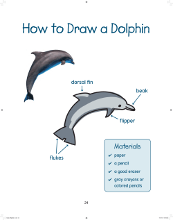


© Copyright 2026