
JVA Perimeter Patrol Installation and Configuration Manual Version:
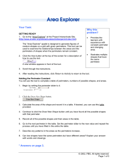
JVA Perimeter Patrol Installation and Configuration Manual Version: Date: 5.2 revision 1 May 2014 JVA Perimeter Patrol™ Introduction Table of Contents 1 Introduction ........................................................................................................................ 3 1.1 Scope and purpose ..................................................................................................... 3 1.2 Other relevant documentation...................................................................................... 3 1.3 JVA Perimeter Patrol ................................................................................................... 4 2 Wiring and architecture considerations for connecting JVA Perimeter Patrol to JVA Security Electric Fence Devices ............................................................................................ 6 2.1 Introducing the Keypad Bus ......................................................................................... 6 2.2 Introducing Keypad Bus Id and the Group Mode configuration property ...................... 6 2.2.1 Keypad Bus Limitations ......................................................................................... 7 2.3 Wiring overview – Keypad Bus and connection to JVA Perimeter Patrol ..................... 7 2.3.1 Wiring overview – serial connection to JVA Perimeter Patrol................................. 8 2.3.2 Wiring overview – Ethernet connection to JVA Perimeter Patrol............................ 9 2.3.3 Devices that connect the computer to the Keypad Bus........................................ 11 2.4 Wiring limitations and best practices .......................................................................... 12 2.5 Using an Ethernet adapter ......................................................................................... 13 2.5.1 Wiring the Ethernet adapter ................................................................................ 13 2.5.2 Configuring Devices for operation with the Ethernet adapter ............................... 14 2.5.3 Debugging an Ethernet adapter .......................................................................... 14 3 Installing JVA Perimeter Patrol software .......................................................................... 17 3.1 System requirements ................................................................................................. 17 3.1.1 Connectivity ........................................................................................................ 17 3.1.2 Security ............................................................................................................... 17 3.1.3 Serial Port ........................................................................................................... 17 3.1.4 Ethernet Port ....................................................................................................... 17 3.2 Uninstall previous versions of JVA Perimeter Patrol software .................................... 18 3.3 Install JVA Perimeter Patrol ....................................................................................... 18 3.3.1 Install Prerequisites ............................................................................................. 18 3.3.2 Install JVA Perimeter Patrol ................................................................................ 19 4 Configuring JVA Perimeter Patrol..................................................................................... 21 4.1 Activate JVA Perimeter Patrol with a licence key ....................................................... 21 4.2 Changing the Administrator password ....................................................................... 25 4.3 Configuring user accounts ......................................................................................... 25 4.3.1 Enabling and disabling user accounts ................................................................. 26 4.3.2 Promoting and demoting users............................................................................ 26 © JVA Technologies Pty Ltd 2014 Version April 2014. Uncontrolled if printed Page 1 of 58 JVA Perimeter Patrol™ Introduction 4.3.3 Summary of user access permissions ................................................................. 26 4.3.4 Configuring full screen mode ............................................................................... 27 4.4 Configuring alarms and email .................................................................................... 28 4.4.1 Alarm Delay Settings ........................................................................................... 29 4.5 Configuring JVA Perimeter Patrol to connect using Serial Communications (RS232 or USB) ............................................................................................................................... 30 4.5.1 Scanning to detect zones .................................................................................... 30 4.5.2 Understanding detected zones ............................................................................ 31 4.5.3 Adding and configuring zones ............................................................................. 31 4.5.4 Other zone configuration utilities ......................................................................... 31 4.6 Configuring JVA Perimeter Patrol to connect using an Ethernet Adapter (Local Area Network) .......................................................................................................................... 32 4.6.1 Connecting JVA Perimeter Patrol to the Ethernet Adapters (PAE212/PAE224) .. 32 4.6.2 Adding electric fence zones to JVA Perimeter Patrol........................................... 38 4.7 Setting up the map image .......................................................................................... 41 4.7.1 Selecting the Map ............................................................................................... 41 4.7.2 Setting the Zoom Level for the Map..................................................................... 42 4.8 Drawing zones on the map ........................................................................................ 43 4.9 Setting the control schedule for a zone ...................................................................... 44 4.10 Configuring IO Boards with JVA Perimeter Patrol .................................................... 46 4.10.1 Configuring Analog Inputs ................................................................................. 47 4.10.2 Configuring Digital Inputs .................................................................................. 48 4.10.3 Digital Input Functions ....................................................................................... 49 4.10.4 Configuring Outputs .......................................................................................... 50 4.11 Zone/Sector/Input/Output Colours ........................................................................... 51 4.12 Map Icons ................................................................................................................ 51 5 Connecting two instances of Perimeter Patrol in Server / Client configuration using the HLI ........................................................................................................................................... 52 5.1 Configuring Perimeter Patrol Server .......................................................................... 52 5.1.1 Configuring Perimeter Patrol Server to accept HLI connections .......................... 52 5.2 Configuring Perimeter Patrol Client............................................................................ 53 5.3 Using the correct IP Address and Port ....................................................................... 55 5.3.1 Connecting Server and Client on LAN ................................................................. 56 5.3.2 Connecting Server and Client on WAN ............................................................... 57 6 Locking down the computer to keep JVA Perimeter Patrol secure ................................... 58 © JVA Technologies Pty Ltd 2014 Version April 2014. Uncontrolled if printed Page 2 of 58 JVA Perimeter Patrol™ Introduction 1 Introduction JVA Perimeter Patrol, a software system for monitoring and commanding JVA Security Electric Fence Devices, is designed exclusively for JVA Technologies Pty Ltd by Pakton Technologies Pty Ltd of Brisbane, Australia. Keep this document secure. 1.1 Scope and purpose This installation and configuration manual is an OEM manual for use by JVA Security System Installers and Administrators. It covers: Wiring and architecture considerations for connecting JVA Perimeter Patrol to JVA Security Electric Fence Devices Installation and configuration of JVA Perimeter Patrol Connecting instances of JVA Perimeter Patrol together in Server / Client configuration Locking down a computer to keep JVA Perimeter Patrol secure 1.2 Other relevant documentation Read this document in conjunction with these other documents: JVA Perimeter Patrol User Manual o User manual for every-day operation of JVA Perimeter Patrol JVA Perimeter Patrol High Level Interface Programmers Guide o Programmers’ guide for using a HLI to connect to Perimeter Patrol from their own custom software Z Series OEM Technical Manual o Installation and configuration instructions for the Z-series range of JVA Security Electric Fence energisers ZM1 OEM Technical Manual o Installation and configuration instructions for the JVA ZM1 Security Electric Fence Zone Monitor ZM20 OEM Technical Manual o Installation and configuration instructions for the JVA ZM20 Security Electric Fence Zone Monitor Ethernet Adapter Manual o Installation and configuration instructions for the PAE212 Perimeter Patrol Interface Board General Purpose IO Technical Manual o Installation and configuration instructions for the PAE222 General Purpose IO Board Ethernet General Purpose IO Technical Manual o Installation and configuration instructions for the PAE224 Ethernet GPIO Board © JVA Technologies Pty Ltd 2014 Version April 2014. Uncontrolled if printed Page 3 of 58 JVA Perimeter Patrol™ Introduction 1.3 JVA Perimeter Patrol Perimeter Patrol provides PC based supervisory control and logging for Pakton designed security electric fence energisers and monitoring systems. A powerful, flexible and intuitive user interface is provided over a stable industry standard database structure. Figure 1 - Screenshots of JVA Perimeter Patrol © JVA Technologies Pty Ltd 2014 Version April 2014. Uncontrolled if printed Page 4 of 58 Introduction JVA Perimeter Patrol™ JVA Perimeter Patrol Features View & Control Energiser Zones View & Control Zone Monitors Support Multiple Sectors Per Zone Map-Oriented Zone Mimic Screen Automatically Control on Schedule Alarm Display and Sound Email on Alarm Log alarms and events 10 Event Alarm Log History Automatically Control Output Relays in Response to Alarms User control output relays Serial Communication Mode Ethernet (TCP/IP) Communication Mode User Authentication Full Screen Mode Preventing Access to Other Applications Event Logging with Viewer and Automatic Archival Administrator’s Full System Controller Integrate other equipment via contact inputs and relay outputs High Level Interface API JVA Perimeter Patrol Specifications Operating System Logging Database (Not available in Mimic or Lite) Communications Interface Minimum CPU Minimum RAM Scheduled Control Mimic Lite ZM Pro - - Microsoft Windows XP / Windows 7 Microsoft SQL Server Compact Edition TCP/IP or Serial Port (USB or built-in) Intel or compatible Pentium III 1 GHz or faster 4GB Repeats: Weekly Granularity: 30 Minutes Email Support SMTP, SSL, Authentication Maximum Number of Zones Mimic 30 Lite 30 ZM 8 (each with up to 20 sectors) Pro Up to 1778 (limit depends on system configuration) User Levels (not available in Mimic or Lite) User View zone voltages and alarms All User tasks above Supervisor Control energisers Close resolved alarms Exit Full Screen Mode All Supervisor tasks above Administrator Modify System Configuration Integration of Legacy Equipment Via contact input and relay outputs © JVA Technologies Pty Ltd 2014 Version April 2014. Uncontrolled if printed Page 5 of 58 JVA Perimeter Patrol™ and architecture considerations for connecting JVA Perimeter Patrol to JVA Security Electric Fence Devices Wiring 2 Wiring and architecture considerations for connecting JVA Perimeter Patrol to JVA Security Electric Fence Devices 2.1 Introducing the Keypad Bus JVA Perimeter Patrol monitors and commands the following JVA Security Electric Fence Devices: Table 1- List of JVA Security Electric Fence Devices Security Electric Fence Device Electric Fence Energiser Zone Monitor Ethernet Adapter IO Board Ethernet IO Board Keypad Purpose To power and monitor zones. A zone is an individual section of electric fence. A zone can be armed or disarmed without affecting other zones. Alarms are raised for individual zones. To monitor a zone that is being powered by another energiser. To provide a bridge between the Keypad Bus and the Local Area Network, allowing Perimeter Patrol to connect to the Keypad Bus via Ethernet. To provide extension inputs and outputs. Inputs accept signals from non-JVA security devices such as motion sensors or gate sensors. Outputs provide a way to send signals to external systems such as sirens, strobes, alarms, watchdog monitors, pumps, gates etc. Combines the function of both the Ethernet Adapter and the IO Board, with the addition of analog input capabilities. To allow security personnel to perform manual configuration or command of JVA devices. Each of the JVA security electric fence devices listed above communicate on a serial data bus that has been given the name Keypad Bus, mostly because it allows the keypad to connect to the devices. 2.2 Introducing Keypad Bus Id and the Group Mode configuration property Each device on a Keypad Bus must be configured with a unique id that identifies it on that Keypad Bus. That unique id is called the Keypad Bus Id and it ranges in value from 1 to 15. When you are installing the devices, you must first connect a keypad directly to the device to set its configuration properties before you connect it to the Keypad Bus with all the other devices attached. The device configured with Keypad Bus Id = 1 becomes the Master device, which is responsible for marshalling communications between all the devices on the Keypad Bus, and for synchronizing the timing of all energisers on the Keypad Bus. Devices configured with Keypad Bus Id = 2 – 15 become Slave devices. In the user manuals for each device, the device’s Keypad Bus Id will be referred to as its Group Mode. You configure the Keypad Bus Id for each device by settings its Group Mode configuration property. © JVA Technologies Pty Ltd 2014 Version April 2014. Uncontrolled if printed Page 6 of 58 JVA Perimeter Patrol™ and architecture considerations for connecting JVA Perimeter Patrol to JVA Security Electric Fence Devices Wiring Refer to each device’s user manual to find out how to set its Group Mode configuration property. After you have used a keypad to configure each device individually, you may connect all the devices together on the Keypad Bus. 2.2.1 Keypad Bus Limitations Device LCD Keypads LED Keypads Devices with a Keypad Bus Id Maximum number of devices 2 1 15 Devices with a Keypad Bus Id include energisers, zone monitors, Ethernet adapters, IO boards and Ethernet IO boards. Note that LCD Keypads must each be configured with their own Keypad Id when attaching more than one to a Keypad Bus, but Keypad Id is independent of the Keypad Bus Id of other devices. Refer to the LCD Keypad’s user manual for more information. 2.3 Wiring overview – Keypad Bus and connection to JVA Perimeter Patrol The Keypad Data bus consists of three wires: Ground (GND), Data (DAT), and Power (+12V). Energisers, Zone Monitors and Ethernet IO Boards supply power to the +12V wire while all other devices consume power from the +12V wire. The maximum number of devices excluding keypads that can be connected to a Keypad Data Bus is 15. The computer that hosts JVA Perimeter Patrol can connect to the JVA Security Electric Fence Devices using serial communications or Ethernet communications over the Local Area Network. The sections below will help you decide which connection configuration you should choose. © JVA Technologies Pty Ltd 2014 Version April 2014. Uncontrolled if printed Page 7 of 58 JVA Perimeter Patrol™ and architecture considerations for connecting JVA Perimeter Patrol to JVA Security Electric Fence Devices Wiring 2.3.1 Wiring overview – serial connection to JVA Perimeter Patrol The image below illustrates a possible wiring scenario for connecting JVA Perimeter Patrol to the Keypad Data Bus using either of the two serial communications systems available. The “Keypad Bus to Serial Converter” device illustrated could be either the PAE051 Keypad Bus to RS232 Converter or the PAE223 Keypad Bus to USB Converter. Notice that one of the Energisers or Zone Monitors is configured with its Group Mode Setting = Master and all other devices are configured with Group Mode Setting = Slave. Figure 2 - Keypad Bus shown using PAE051/PAE223 converters to connect to JVA Perimeter Patrol using RS232/USB cable © JVA Technologies Pty Ltd 2014 Version April 2014. Uncontrolled if printed Page 8 of 58 JVA Perimeter Patrol™ and architecture considerations for connecting JVA Perimeter Patrol to JVA Security Electric Fence Devices Wiring 2.3.2 Wiring overview – Ethernet connection to JVA Perimeter Patrol The image below illustrates a possible wiring scenario for connecting JVA Perimeter Patrol to the Keypad Data Bus via the Local Area Network using either of the Ethernet adapters available. The “Master Ethernet Device” illustrated could be either the PAE212 Ethernet Adapter Device or the PAE224 Ethernet IO Board. Notice that the Master Ethernet Device is configured with its Group Mode Setting = Master and all other devices are configured with Group Mode Setting = Slave. Figure 3 - Keypad bus shown using PAE212/PAE224 Ethernet boards to connect to JVA Perimeter Patrol using the Local Area Network © JVA Technologies Pty Ltd 2014 Version April 2014. Uncontrolled if printed Page 9 of 58 JVA Perimeter Patrol™ and architecture considerations for connecting JVA Perimeter Patrol to JVA Security Electric Fence Devices Wiring The Local Area Network can be used to connect multiple PAE212 Ethernet Adapter Devices and/or PAE224 Ethernet IO Boards to JVA Perimeter Patrol. This provides JVA Perimeter Patrol with the ability to monitor and command multiple groups of Security Electric Fence devices. Figure 4 - Using the Local Area Network (LAN) to connect JVA Perimeter Patrol to multiple groups of JVA Security Electric Fence devices © JVA Technologies Pty Ltd 2014 Version April 2014. Uncontrolled if printed Page 10 of 58 JVA Perimeter Patrol™ and architecture considerations for connecting JVA Perimeter Patrol to JVA Security Electric Fence Devices Wiring 2.3.3 Devices that connect the computer to the Keypad Bus Local Area Network (LAN) Device: PAE212 Ethernet Adapter Device Comments: JVA Perimeter Patrol can be connected to multiple groups of Security Electric Fence devices. Supports IO Boards Device: PAE224 Ethernet IO Board Comments: JVA Perimeter Patrol can be connected to multiple groups of Security Electric Fence devices. Supports IO Boards Serial Port using USB Device: PAE223 Keypad Bus to USB Converter Comments: JVA Perimeter Patrol can only be connected to one of these devices, and therefore can only be connected to one group of Security Electric fence devices. Supports IO Boards Serial Port using RS232 Device: PAE051 Keypad Bus to RS232 Converter Comments: JVA Perimeter Patrol can only be connected to one of these devices, and therefore can only be connected to one group of Security Electric fence devices. Supports IO Boards © JVA Technologies Pty Ltd 2014 Version April 2014. Uncontrolled if printed Page 11 of 58 JVA Perimeter Patrol™ and architecture considerations for connecting JVA Perimeter Patrol to JVA Security Electric Fence Devices Wiring 2.4 Wiring limitations and best practices For best results, the Master device should be connected closest to the control / monitoring unit (Keypad, computer or LCD display). Maximum resistance from the keypad to the Master device on the GND wire or the DATA wire is 4.5 Ohm. Maximum resistance from the Master device to any other device on the GND wire or the DATA wire is 150 Ohms, maximum capacitance allowed between the GND and DATA wires measured at the Master device is 150nF Figure 5 – Connecting a PAE051/PAE223 to JVA Perimeter Patol via RS232 or USB cable Tip! “Two wires as one” technique: If you are using CAT 5 cable for the Keypad Bus, you will have enough spare wires in the cable to use this clever trick for halving their resistance: Join together two wires at both ends to have them act together as a single wire. Make sure you join them together as they enter and exit each device. Note: CAT 5 DC loop resistance is 0.188 Ohm / meter or 0.094 Ohm / meter if you are using the “two wires as one” technique. It is worth measuring the capacitance between these two wires at the Master to make sure it doesn’t exceed this value. Based on this limitation, we recommend that the maximum length of cable be 1.5km. If you are using 3 or more energisers, the Master device should be in centre of the cable and the energisers should be evenly spaced. Star or Ring Network configurations can be used and are recommended for large installations. © JVA Technologies Pty Ltd 2014 Version April 2014. Uncontrolled if printed Page 12 of 58 JVA Perimeter Patrol™ and architecture considerations for connecting JVA Perimeter Patrol to JVA Security Electric Fence Devices Wiring 2.5 Using an Ethernet adapter If you are using the Local Area Network to connect JVA Perimeter Patrol to the JVA Security Electric Fence Devices, you will need to use either the PAE212 Ethernet Adapter Device or the PAE224 Ethernet IO Board. 2.5.1 Wiring the Ethernet adapter PAE212 Wire the Keypad Bus into the adapter (+12V, GND, DAT). o Energisers, Zone Monitors, and Ethernet IO Boards supply power to the Keypad Bus. o All other devices consume power from the Keypad Bus. Connect the Ethernet port of the PAE212 to the building Local Area Network (LAN) Figure 6 - PAE212 Ethernet Adapter Device © JVA Technologies Pty Ltd 2014 Version April 2014. Uncontrolled if printed Page 13 of 58 JVA Perimeter Patrol™ and architecture considerations for connecting JVA Perimeter Patrol to JVA Security Electric Fence Devices Wiring PAE224 Wire Power into the adapter (+12V, GND). Wire the Keypad Bus into the adapter (DAT, GND). Only wire +12V if the PAE224 is used to directly power a keypad. Connect the Ethernet port of the PAE224 to the building Local Area Network (LAN) Figure 7 - PAE224 Ethernet IO Board 2.5.2 Configuring Devices for operation with the Ethernet adapter The PAE212 Ethernet Adapter Device and PAE224 Ethernet IO Board are configured with their Group Mode property = 1, which means it is the Master Device and has a Keypad Bus Id = 1. Therefore all other devices must have their Group Mode set to a value between 2 and 15, which will configure them to be slaves. Remember, no two devices can have the same Keypad Bus Id. 2.5.3 Debugging an Ethernet adapter 2.5.3.1 Return to Factory Defaults (Jumper J4) If for some reason the PAE212 Ethernet Adapter Device or PAE224 Ethernet IO Board is not recognised by Perimeter Patrol, or it is not working as expected, it may be beneficial to return it to Factory Defaults. To do so: Remove the black jumper located at J4 (see previous images for jumper location). Depower the Ethernet adapter by removing the Power connector (PAE224 only) and the Keypad Bus connector. Repower the Ethernet adapter by re-attaching the Power connector (PAE224 only) and the Keypad Bus connector. © JVA Technologies Pty Ltd 2014 Version April 2014. Uncontrolled if printed Page 14 of 58 JVA Perimeter Patrol™ and architecture considerations for connecting JVA Perimeter Patrol to JVA Security Electric Fence Devices Wiring When the Power and Keypad Bus connection is returned, the LEDs D5 and D6 and D7 (see image below) will light for ½ a second. The D7 blink shows the board loading the Factory Defaults. Replace the jumper across both pins of J4. 2.5.3.2 LED Indications for the Ethernet adapter LEDs on the PAE212 and PAE224 can be used to get valuable debugging information when you are installing or troubleshooting its operation. The position of each LED is shown in the images below, and the table following it explains the function of each LED. Figure 8 - LED Indications for the PAE212 Ethernet Adapter Device Figure 9 – LED Indications for the PAE224 Ethernet IO Board © JVA Technologies Pty Ltd 2014 Version April 2014. Uncontrolled if printed Page 15 of 58 JVA Perimeter Patrol™ and architecture considerations for connecting JVA Perimeter Patrol to JVA Security Electric Fence Devices Wiring Table 2 - LED Functions for the PAE212 Ethernet Adapter Device Name Power Energiser Synch Energiser Data Zone Monitor Data LAN Connected LAN Activity ID Colour Function D4 Green ON when the Ethernet Device has power D7 Red Blink once per second when the energisers are synchronised D5 Red Blinks rapidly (one blink per energiser) when receiving data from the energisers D6 Red Blinks rapidly (one blink per zone monitor) when receiving data from the zone monitors D8 Green On when connected to the Local Area Network (LAN) D9 Green Blinks when sending information to JVA Perimeter Patrol © JVA Technologies Pty Ltd 2014 Version April 2014. Uncontrolled if printed Page 16 of 58 JVA Perimeter Patrol™ Installing JVA Perimeter Patrol software 3 Installing JVA Perimeter Patrol software 3.1 System requirements Operating System Microsoft Windows XP / Windows 7 Do not use Windows Vista or any earlier versions of Windows CPU Intel or compatible Pentium III 1GHz or faster. Use the Windows Task Manager to make sure the CPU is using less than 5% of its capacity while JVA Perimeter Patrol is running. Hard Drive 120Gb with at least 50% free space JVA Perimeter Patrol log files can grow to large sizes. Ensure your computer’s hard drive is large enough to hold them. RAM 4GB Use the Windows Task Manager to make sure there is at least 1GB of free RAM remaining after JVA Perimeter Patrol is running. 3.1.1 Connectivity If you intend using the following features of JVA Perimeter Patrol, ensure that the host computer has a stable, active internet connection: Email High Level Interface (requires static IP Address) 3.1.2 Security Lock down the computer according to section Locking down the computer to keep JVA Perimeter Patrol secure below. 3.1.3 Serial Port If you intend connecting to JVA Security Electric Fence devices using Serial Port or USB Port, ensure your computer has a spare port of the correct type available. 3.1.4 Ethernet Port If you intend connecting to JVA Security Electric Fence Devices using the Local Area Network, ensure your computer has an Ethernet port or wireless connection available for connecting to the required LAN. © JVA Technologies Pty Ltd 2014 Version April 2014. Uncontrolled if printed Page 17 of 58 JVA Perimeter Patrol™ Installing JVA Perimeter Patrol software 3.2 Uninstall previous versions of JVA Perimeter Patrol software Before installing JVA Perimeter Patrol on a computer, you should make sure that previous versions have been uninstalled first. 1. Go to Control Panel Programs and Features and search for “Perimeter Patrol”. 2. Select any items that appear in the program list 3. Then click the Uninstall button. 1 3 2 Figure 10 - Uninstalling JVA Perimeter Patrol 3.3 Install JVA Perimeter Patrol 3.3.1 Install Prerequisites The first prerequisite you must install is WinPcap, a utility that helps Perimeter Patrol communicate with the Ethernet Adapter devices on the Local Area Network. Using the installation CD you have been provided, open the WinPcap folder and then run the file WinPcap_4_1_2.exe to install WinPcap. 2 1 Figure 11 - Installing WinPcap © JVA Technologies Pty Ltd 2014 Version April 2014. Uncontrolled if printed Page 18 of 58 JVA Perimeter Patrol™ Installing JVA Perimeter Patrol software The next prerequisite to install is Microsoft SQL Server Compact Edition so that Perimeter Patrol can save record logs to the hard disk. Using the installation CD you have been provided; open the SQL Server Compact Edition folder. There are two setup files in here for you to run. If your computer has a 32-bit CPU, run the file with x86 in the filename. If your computer has a 64-bit CPU, you must RUN BOTH files, starting first with the x86 file and then running the other. If you’re not sure how many bits your computer CPU has, just run both files in the order shown. 1 2 3 Figure 12 - Installing Microsoft SQL Server Compact Edition 3.3.2 Install JVA Perimeter Patrol Using the installation CD you have been provided, find the setup.exe file and double-click to open it. Figure 13 - Open the JVA Perimeter Patrol installation package After the installation program opens, click Next, Yes or Finish until the installation is complete. © JVA Technologies Pty Ltd 2014 Version April 2014. Uncontrolled if printed Page 19 of 58 JVA Perimeter Patrol™ Installing JVA Perimeter Patrol software You can start JVA Perimeter Patrol by clicking its icon on your desktop or by searching for it in your Windows start menu. Below is a picture of how the JVA Perimeter Patrol icon may look on your computer’s desktop. To find it in your Windows start menu, click Start -> All Programs -> JVA -> JVA Perimeter Patrol. Figure 14 - JVA Perimeter Patrol desktop icon © JVA Technologies Pty Ltd 2014 Version April 2014. Uncontrolled if printed Page 20 of 58 JVA Perimeter Patrol™ Configuring JVA Perimeter Patrol 4 Configuring JVA Perimeter Patrol 4.1 Activate JVA Perimeter Patrol with a licence key When you start JVA Perimeter Patrol, it will open immediately in Lite mode, which gives you limited, free functionality. The first thing you will want to do is enable the advanced features of JVA Perimeter Patrol by activating them with a licence key. 1. 2. 3. 4. Click Setup Activate Licence Enter your name Enter your organization name Click the Request Activation Code button 1 2 3 4 Figure 15 - Requesting a licence key - part 1 © JVA Technologies Pty Ltd 2014 Version April 2014. Uncontrolled if printed Page 21 of 58 JVA Perimeter Patrol™ Configuring JVA Perimeter Patrol An activation code window will appear with a code. 1. Click the Copy to Clipboard button 2. Press the Close button 1 2 Figure 16 - Requesting a licence key - part 2 3. Click on the hyperlink in the Product Activation window to open an Internet Browser at the Perimeter Patrol Activation page. If the hyperlink does not work, open an Internet Browser and set the address to www.jva-fence.com.au/ppKey.php 3 Figure 17 - Requesting a licence key - part 2 © JVA Technologies Pty Ltd 2014 Version April 2014. Uncontrolled if printed Page 22 of 58 JVA Perimeter Patrol™ Configuring JVA Perimeter Patrol The Website for requesting an activation code should appear in your Internet Browser. 1. Click into the Activation Request Code box and press Ctrl-V to paste the code 2. Enter the Activation Coupon into this box. Your vendor should have provided you with one 3. Enter the email address you want the activation code to be delivered to 4. Press the Submit button 2 1 The Email Success page should now be shown. You can close the Internet Browser down now 3 4 You will receive an email with your new licence key. 1. 2. 3. 4. 5. Copy the licence key from the email Click the first box in the product activation window Press Ctrl-V to paste the licence key Click the Activate button The program will shut down. Restart it 2 4 Figure 18 - Entering your licence key © JVA Technologies Pty Ltd 2014 Version April 2014. Uncontrolled if printed Page 23 of 58 JVA Perimeter Patrol™ Configuring JVA Perimeter Patrol After you have started JVA Perimeter Patrol, it will prompt you to enter your login username and password. JVA Perimeter Patrol comes packaged with the following default credentials: Username: Admin Password: 0000 Enter these details in the login prompt and click OK. You may be wondering at this point what the Connection Settings button is for, but we’ll introduce it later in this installation and configuration manual. Figure 19 - Logging in for the first time © JVA Technologies Pty Ltd 2014 Version April 2014. Uncontrolled if printed Page 24 of 58 JVA Perimeter Patrol™ Configuring JVA Perimeter Patrol 4.2 Changing the Administrator password Change the Administrator password to a value that is known only to you and other system administrators. 1. Click Setup System Configuration 2. Select the Users tab 3. Click the Change Administrator Password button. 1 2 3 Figure 20 - Changing the Administrator password 4.3 Configuring user accounts While the Users configuration tab is open, you may like to take the opportunity to setup the user accounts. JVA Perimeter Patrol comes preconfigured with four default User-level accounts and four default Supervisor-level accounts. Click to select any user and modify its username and password. Click the Add buttons to create a new user. Click the Remove buttons to remove any selected user. Modify a selected user’s username and password. © JVA Technologies Pty Ltd 2014 Version April 2014. Uncontrolled if printed Page 25 of 58 JVA Perimeter Patrol™ Configuring JVA Perimeter Patrol 4.3.1 Enabling and disabling user accounts Sometimes you may need to prevent a certain user account from being able to log in. An example of this may be when somebody from your company goes away on holidays. Select their user name Click the Enabled check box to enable and disable their account. 4.3.2 Promoting and demoting users A user account in the Users Group has the lowest level of access permissions. To give that user account a higher level of access permissions, you can promote it to the Supervisor Group by clicking the Move to Supervisors button. Similarly, you can demote any user account from the Supervisor Group down to the User Group by clicking the Move to Users button. 4.3.3 Summary of user access permissions Users View zone voltages and alarms Control energisers Close resolved alarms Exit full screen mode System Configuration Supervisors Administrators Most of the time, JVA Perimeter Patrol operators only require User access permissions level. It is expected that you will setup JVA Perimeter Patrol so that the operators have to request a manager with supervisor-level access permissions to perform higher level functions for them. © JVA Technologies Pty Ltd 2014 Version April 2014. Uncontrolled if printed Page 26 of 58 JVA Perimeter Patrol™ Configuring JVA Perimeter Patrol 4.3.4 Configuring full screen mode Full screen mode is the remaining setting for you to configure in the Users panel. It is expected that you will configure JVA Perimeter Patrol to run in full screen mode and block operators from accessing other programs on the computer. To achieve this, you will have to set a password to prevent operators from exiting full screen mode. This password is only required when the operator has logged into JVA Perimeter Patrol with an account that has user-level access permissions. The password cannot prevent supervisors from exiting full-screen mode. Figure 21 - Setting a password to prevent operators from exiting full screen mode © JVA Technologies Pty Ltd 2014 Version April 2014. Uncontrolled if printed Page 27 of 58 JVA Perimeter Patrol™ Configuring JVA Perimeter Patrol 4.4 Configuring alarms and email JVA Perimeter Patrol can send emails whenever an alarm occurs if the computer you have installed it on is connected to the internet. Click Setup System Configuration and select the Alarms & Email tab The first section of the Email Settings selects the type of Emails you want to receive. You must select one of these options to receive emails. Figure 22 – Enable Emails You must provide a reliable outgoing email server (SMTP), From and To Addresses. Click the Test SMTP Settings button confirm that email settings are working correctly. To change the default Email Subject, check the Use Custom Email Subject box. Type your new subject into the text box below. This can be very useful when using an Email2SMS service. Figure 23 – Configure Emails settings © JVA Technologies Pty Ltd 2014 Version April 2014. Uncontrolled if printed Page 28 of 58 JVA Perimeter Patrol™ Configuring JVA Perimeter Patrol 4.4.1 Alarm Delay Settings Section 2 of the configuration settings shown below contains settings that you can configure to prevent JVA Perimeter Patrol from reacting too quickly to changing alarm conditions. The Alarm Delay setting allows you to specify the number of seconds an alarm condition must be present before JVA Perimeter Patrol logs it and raises an alarm. The Alarm Reset Delay setting allows you to specify the number of seconds an alarm condition must be gone before JVA Perimeter Patrol will mark the alarm as being resolved. Keep these values as small as possible to make JVA Perimeter Patrol react quickly to alarm circumstances. Increase them if you find that intermittent alarm conditions are causing JVA Perimeter Patrol to cycle too rapidly in and out of alarm state. Figure 24 – Configure Emails settings © JVA Technologies Pty Ltd 2014 Version April 2014. Uncontrolled if printed Page 29 of 58 JVA Perimeter Patrol™ Configuring JVA Perimeter Patrol 4.5 Configuring JVA Perimeter Patrol to connect using Serial Communications (RS232 or USB) 4.5.1 Scanning to detect zones 1. Click Setup System Configuration 2. Click Zones & Connections tab 3. Select USB, RS232 or Keypad Bus 4. Select a serial Com Port to open a. You must have devices attached before com ports become available 5. Click on the Open button 6. Click the Add / Remove Zones button 7. Click the Scan button 1 5 4 2 3 7 8 6 Figure 25 - Configuring zones using serial communications 8. After performing the scan, detected zones will begin to appear in the Detected Zones list. A zone is a section of fence that is powered by an energiser. The zone is individually monitored and can be armed or disarmed independently from other zones. Some energisers can power more than one zone. © JVA Technologies Pty Ltd 2014 Version April 2014. Uncontrolled if printed Page 30 of 58 JVA Perimeter Patrol™ Configuring JVA Perimeter Patrol 3 4 1 2 5 6 Figure 26 – Adding and Editing zones 4.5.2 Understanding detected zones Each detected zone has a unique descriptor which helps you identify it. The unique descriptor has the form: <Device Keypad Bus ID>:<Zone Index> - (<Device Type>) The first detected zone in the illustration above has the descriptor: 3:1 – (Z28), which has the following meaning: The device powering or monitoring the zone has a Keypad Bus ID = 3. This zone is the first zone in the device. The zone belongs to a device of “Z28” type. 4.5.3 Adding and configuring zones Choose the zones you wish to monitor and control with JVA Perimeter Patrol. Add them to the Active Zones list on the right. You can add them individually or all at once using the Check All and Add Checked buttons (1 and 2) Give the zones user-friendly names (3) If the zone’s device type has not been correctly identified, you can modify it (4) Remember to Save (5) your zones before closing (6) the window 4.5.4 Other zone configuration utilities You can re-order zones in the Active Zones list using the Move Up and Move Down button in the top-right of the zone configuration window. You can manually add zones without scanning by using the Add New button at the bottom of the Active Zones list. © JVA Technologies Pty Ltd 2014 Version April 2014. Uncontrolled if printed Page 31 of 58 JVA Perimeter Patrol™ Configuring JVA Perimeter Patrol 4.6 Configuring JVA Perimeter Patrol to connect using an Ethernet Adapter (Local Area Network) 4.6.1 Connecting JVA Perimeter Patrol to the Ethernet Adapters (PAE212/PAE224) 1. Click Setup System Configuration 2. Click Connect via: Ethernet 3. Click Add / Remove Zones 1 2 3 Figure 27 - Enter Add / Remove Zones © JVA Technologies Pty Ltd 2014 Version April 2014. Uncontrolled if printed Page 32 of 58 JVA Perimeter Patrol™ Configuring JVA Perimeter Patrol 4.6.1.1 WinPcap Error Message To communicate with JVA devices by TCP/IP protocol, JVA Perimeter Patrol requires that your computer have software called WinPcap installed. If WinPcap is not already installed, you will see a red error message at the bottom of the Add/Remove Zones window, as shown in the image below: Figure 28 - WinPcap is not installed To rectify this situation, exit Perimeter Patrol and then find the WinPcap installation file included in the JVA Perimeter Patrol setup bundle. Run this file to install WinPcap. See section 3.3.1 © JVA Technologies Pty Ltd 2014 Version April 2014. Uncontrolled if printed Page 33 of 58 JVA Perimeter Patrol™ Configuring JVA Perimeter Patrol 4.6.1.2 Scanning for devices and zones 1. Select the network device that you want to use 2. Click the Scan button 1 2 Figure 29 - Scan for zones © JVA Technologies Pty Ltd 2014 Version April 2014. Uncontrolled if printed Page 34 of 58 JVA Perimeter Patrol™ Configuring JVA Perimeter Patrol A list of detected Ethernet Devices will appear in the left column. A list of detected zones will appear in the middle column. The image below shows an example. This document will focus on the detected Ethernet Devices and their configuration first, and work with the detected zones in a later section of this document. Figure 30 - Detected Ethernet devices in the left-most column. Detected zones are in the middle column. 4.6.1.3 Ethernet Adapter Descriptor In the example image above, two Ethernet Adapters have been detected. The first in the list has the following three-part descriptor: ETH-161372 - 192.168.0.26 - ID0 Examples of each part of a descriptor are given in the table below. Table 3 - Properties contained in the descriptor of a PAE212 Ethernet Adapter Device Property Name Network Name IP Address Ethernet ID Example 1 ETH-161372 192.168.0.26 ID0 Example 2 ETH-161458 192.168.0.28 ID1 Each part of the three-part descriptor should be unique. No Ethernet Adapter should share the same Network Name, IP Address or Ethernet ID as another. The last 6 digits of the Network name are the same as the serial number of the device, which you can find as a sticker on the device’s printed circuit board. © JVA Technologies Pty Ltd 2014 Version April 2014. Uncontrolled if printed Page 35 of 58 JVA Perimeter Patrol™ Configuring JVA Perimeter Patrol 4.6.1.4 Using JVA Perimeter Patrol to configure an Ethernet Adapter Click the first Ethernet Device in the list of discovered Ethernet Devices. Its configuration settings will appear underneath. Figure 31 - Configuration Settings for a PAE212 Ethernet Adapter Device 4.6.1.4.1 Ethernet ID setting Ethernet IDs are used by the Ethernet Adapters for communication between each other, particularly for the purpose of synchronizing energisers on the entire network. Every Ethernet Adapter must have a unique Ethernet ID setting. Click the Check All button to select all the Ethernet Adapters Click the Assign Unique Ethernet Ids to Checked Devices button Click the Commit Changes to Ethernet Devices button 4.6.1.4.2 Network settings JVA Perimeter Patrol can contact the Ethernet Adapters by two methods, ordered from most recommended to least recommended. Static IP Address (DHCP disabled) Network Name (DHCP enabled) Choose a system depending on the configuration of the LAN (Local Area Network), which you may not have control over. Most LANs will permit you to use static IP Address but some will not. Some LANs will permit you to contact the Ethernet Adapters using their Network Name (DHCP) but some will not. © JVA Technologies Pty Ltd 2014 Version April 2014. Uncontrolled if printed Page 36 of 58 JVA Perimeter Patrol™ Configuring JVA Perimeter Patrol 4.6.1.4.3 Network settings – Static IP Address (DHCP disabled) system If you decide to use the Static IP Address (DHCP disabled) system, follow these instructions. Choose a Subnet Mask that is NOT being used by other computers or devices on the network. Other computers on the network most commonly use a Subnet Mask of 255.255.255.0. Choose a different value to avoid IP Address conflicts. For each Ethernet Adapter in the Detected Ethernet Devices List: o Click the device to select it o Click the DHCP setting to disable it o Edit the Static IP, Subnet Mask, Gateway and DNS Click the Commit Changes to Ethernet Devices button Make sure that you give each device a unique static IP address. The Gateway and DNS settings are usually standard and don’t need to be changed. Check with the Local Area Network (LAN) administrator if the LAN uses non-standard Gateway or DNS settings. Figure 32 - Configuring each PAE212 Ethernet Adapter Device to use Static IP Address. Note that DHCP is UNSELECTED. © JVA Technologies Pty Ltd 2014 Version April 2014. Uncontrolled if printed Page 37 of 58 JVA Perimeter Patrol™ Configuring JVA Perimeter Patrol 4.6.1.4.4 Network Settings – Network Name (DHCP enabled) system If you decide to use the Network Name (DHCP enabled) system, follow these instructions: Choose a Subnet Mask that is NOT being used by other computers or devices on the network. Other computers on the network most commonly use a Subnet Mask of 255.255.255.0. Choose a different value to avoid IP Address conflicts. For each PAE212 Ethernet Adapter Device in the Detected Ethernet Devices list: o Click the device to select it o Click the DHCP setting to enable it o Edit the Subnet Mask to your chosen value Click the Commit Changes to Ethernet Devices button 4.6.1.4.5 Clear known energisers list Ethernet Adapters remember the energisers and zone monitors that have been connected to them in the past, even if the energiser or zone monitor has been removed from the Keypad Bus. Use the Clear Known Energisers List button to command the Ethernet Adapter to “forget” about all the energisers it has seen in the past. This is best performed while all devices are disarmed. The Ethernet Adapter will quickly determine the number and type of the devices connected. Returning the Ethernet Adapter to its factory default settings (explained above in this document) will achieve the same result, but if you do that you will also have to re-configure its Network settings inside JVA Perimeter Patrol. 4.6.2 Adding electric fence zones to JVA Perimeter Patrol When you have finished configuring the Ethernet Adapters, you will be ready to configure JVA Perimeter Patrol for monitoring and controlling each individual section of electric fence, called a zone. All the zones that were detected will be displayed in the Detected Zones list, as illustrated in (Area 1) of the image below. 1 © JVA Technologies Pty Ltd 2014 Version April 2014. Uncontrolled if printed Page 38 of 58 JVA Perimeter Patrol™ Configuring JVA Perimeter Patrol 4.6.2.1 Using the electric fence zone descriptor to identify zones Each zone can be uniquely identified from its descriptor as displayed in the Detected Zones list. To understand the descriptor, we will use our understanding of the network architecture described earlier in this document. Zones belong to Security Electric Fence Devices such as energisers and zone monitors. A zone is a section of electric fence that is individually armed, disarmed, and monitored. Alarms can be raised for each zone. Security Electric Fence Devices can have more than one Zone each. Security Electric Fence Devices are grouped on a Keypad Bus together with a Ethernet Adapter. There can be many Ethernet Adapters, each with its own group of Security Electric Fence Devices. The first three fields of a zone’s descriptor, separated by the ‘:’ character, uniquely identify the zone by describing its position with respect to the network of devices. The final field of the descriptor, inside “()” brackets, is just a helper that tells you the type of device that powers or monitors the zone. The descriptor of the first zone in the list in the image above is ETH-161372:2:1 (Z14) Example Description Descriptor Part 1 ETH-161372 Network Name of the Ethernet Adapter. The last six digits are the same as the serial number of the device. Descriptor Part 2 2 Keypad Bus Id of the device powering or monitoring the zone. Descriptor Part 3 1 Index of the zone with respect to the other zones powered or monitored by the same device. Also called the zone’s channel. Descriptor Part 4 (Z14) The type of device that is powering or monitoring the zone. 4.6.2.1.1 Identifying devices from the zone descriptor It may be helpful to note that the first two fields in the zone’s descriptor also uniquely identify the device that is powering or monitoring the zone. The first field in the descriptor, the network name of the Ethernet Adapter, can help you determine which Keypad Bus the device belongs to. The second field in the descriptor, the Keypad Bus Id, uniquely identifies the device with respect to the Keypad Bus that it is connected to. 4.6.2.1.2 Choosing which zones to add to JVA Perimeter Patrol Now that you understand how to identify zones from their descriptor, you can choose which zones you want to add to JVA Perimeter Patrol, and which zones you’d like to ignore. For example, if an energiser can power two zones but you only use one zone, you would like to ignore the zone that is not being used. © JVA Technologies Pty Ltd 2014 Version April 2014. Uncontrolled if printed Page 39 of 58 JVA Perimeter Patrol™ Configuring JVA Perimeter Patrol 4.6.2.2 Adding zones Choose the zones you wish to view, monitor and control in JVA Perimeter Patrol as demonstrated in the image below (step 1). If you don’t want to have all the available zones, you may add and remove them individually using the checkbox beside each zone. Once you have selected all of the zones that you wish to use with JVA Perimeter Patrol, press the “Add Checked >>” button (step 2). Select any zone in the active zone list (step 3) and then give it a name (step 4) that is friendly and easy to understand. This is the name that JVA Perimeter Patrol will display to the users. Be careful to make sure you set the Contact Using property correctly (step 5). The table below shows you which value you should use depending on the network system that you are using to connect to the Ethernet Adapters. Network connection method Static IP Address (DHCP disabled) Network Name (DHCP enabled) Contact zone using IP Address Network Name Be sure to save your changes (step 6). Figure 33 - Adding and naming zones © JVA Technologies Pty Ltd 2014 Version April 2014. Uncontrolled if printed Page 40 of 58 JVA Perimeter Patrol™ Configuring JVA Perimeter Patrol 4.7 Setting up the map image 4.7.1 Selecting the Map With zones added to JVA Perimeter Patrol, you are ready to setup the map image that will be displayed to the system operators. To setup the map image in JVA Perimeter Patrol, most system installers will use Google Earth to capture an aerial view of the site to be secured. 1. 2. 3. 4. Save a copy of the site aerial view to your hard drive. Click Setup System Configuration Select the Mapping tab Click the Browse button and select the map image to be used in JVA Perimeter Patrol. When you close the System Configuration window, JVA Perimeter Patrol’s background map image will change to the image you selected. You may notice two more buttons on this tab. The Reset Zone Label Positions button causes all the zone labels on the configuration map to be placed in their original position in the top left corner. The Reset Zone Lines button causes all the zone lines to be erased from the map. These buttons are a good way to quickly erase all your previous drawings so that you can start drawing the zones on the map image again. 2 3 4 Figure 34 - Choosing a map image © JVA Technologies Pty Ltd 2014 Version April 2014. Uncontrolled if printed Page 41 of 58 JVA Perimeter Patrol™ Configuring JVA Perimeter Patrol 4.7.2 Setting the Zoom Level for the Map If your Map is a high resolution image and you will have a lot of zones to be displayed, you may want to add some Zoom Levels to Perimeter Patrol. 1. Select the Maximum Zoom level you need. You may want to start at the highest (9x) level, draw your zone lines while zoomed in and then decide later what is acceptable The zoom feature provides 5 steps between 1x zoom and the Maximum Zoom configured. To zoom into a section of the map, you can use the slider at the top right side of the Map, or use the Mouse Scroll Wheel. When using the Scroll Wheel, the map will centre the zoom at the current cursor position in the map. Moving around a Zoomed map is easy, there is a horizontal and vertical slide bar at the bottom and right side of the map. An easier way is to use the mouse by left clicking then dragging the map. This is similar to other Map systems you probably have already used. 2. Checking the Automatically Zoom To Active Alarm box will allow Perimeter Patrol to take control of the Zoom functionality 3. The zoom will only occur when the Mouse has been left idle for the specified time Any new alarm that occurs will be centred on the Map at the Maximum zoom level required to fit the entire Zone into the screen 4. This zoom level will be maintained for this specified time 5. After which, the map will return to either: Full Screen: The entire Map will be displayed Active Alarms: All of the Active Alarms will fill the Map View Active and Resolved Alarms: All open alarms will fill the Map View If the Full Screen Option is not chosen, then after the ‘Idle’ time (3), the Map will automatically return to Full Screen. 1 3 4 2 5 Figure 35 – Zoom settings © JVA Technologies Pty Ltd 2014 Version April 2014. Uncontrolled if printed Page 42 of 58 JVA Perimeter Patrol™ Configuring JVA Perimeter Patrol 4.8 Drawing zones on the map With your zones configured and the map image correct, it’s time for you to draw the zones on the map. You can do this on the actual map itself. Move the zone labels Start by looking for the zone labels. They are usually all in the top left corner of the map. When you have found the labels, you can drag each of them to the appropriate place on the map. An example zone label is shown in the image below. Hold down the Shift key and drag the label with your mouse. Draw the zone lines Right-click on the zone label and select Draw Line Click on the map where you want the zone line to begin. Click at each point where the zone line should go to. Right-click at the final point to end the drawing session. Figure 36 - Begin drawing zone lines by right-clicking on the zone label and selecting "Draw Line" © JVA Technologies Pty Ltd 2014 Version April 2014. Uncontrolled if printed Page 43 of 58 JVA Perimeter Patrol™ Configuring JVA Perimeter Patrol Figure 37 - Example zone lines drawn around the perimeter of an example site 4.9 Setting the control schedule for a zone JVA Perimeter Patrol will allow you to setup an automatic control schedule for each zone. Click Setup Configuration (1) Click Zones & Connections (2) Select the zone you want to set the control schedule for (3) Click Control Schedule (4) Click on each time period to set it to any of the following values: (5) o Arm High Power o Arm Low Power o Disarm After setting a value in a single time slot, you can drag it to fill a range of timeslots with the same value. This can make it very fast and simple to set complicated schedules, removing the need for you to individually click each timeslot. If you wish to apply the same schedule to all the other zones, click the Apply Schedule to all Zones button (6) © JVA Technologies Pty Ltd 2014 Version April 2014. Uncontrolled if printed Page 44 of 58 JVA Perimeter Patrol™ Configuring JVA Perimeter Patrol The zone in the example shown below is disarmed at all times except 2:00am to 6:00am on Monday when it is armed at high power. Figure 38 - Setting the control schedule for a zone © JVA Technologies Pty Ltd 2014 Version April 2014. Uncontrolled if printed Page 45 of 58 JVA Perimeter Patrol™ Configuring JVA Perimeter Patrol 4.10 Configuring IO Boards with JVA Perimeter Patrol Ethernet and General Purpose IO Boards are added to JVA Perimeter Patrol in the same way as zones. If all inputs on an Ethernet IO Board are configured as digital inputs, then the board will show up as a single zone with a Keypad Bus ID of 1, and the name “Analog IO Expander”, a General Purpose IO board will be have the name “In/Out Expander” Figure 39 –IO Boards with all Digital Inputs When one or more inputs on an Ethernet IO Board are configured as analog inputs (see the Ethernet General Purpose IO Technical Manual), each will be represented by a single zone with the Keypad Bus ID of 1. The Channel number of the zone will represent the analog input number. This will be followed by the device description of “Analog IO Expander”. The image below shows an Ethernet IO Board with inputs 2 and 3 configured as analog inputs: Figure 40 – Adding an Ethernet IO Board with inputs configured as analog inputs Proceed to edit the zone details as you would for a normal electric fence zone, giving the zone a friendly name and ensuring that its other details are correct, and saving your changes (see Adding zones on page 40). © JVA Technologies Pty Ltd 2014 Version April 2014. Uncontrolled if printed Page 46 of 58 JVA Perimeter Patrol™ Configuring JVA Perimeter Patrol 4.10.1 Configuring Analog Inputs Inputs on the Ethernet IO Board that are configured as analog inputs can be used for measuring an external analog signal. This signal can generate alarms if it falls outside of a specified range. If you wish to use either of these functions: Click Setup System Configuration Click Zones & Connections Select the zone corresponding to the desired analog input On the Settings tab, the Analog Input Settings boxes can be used to adjust the offset, scaling factor and units of the input, allowing the measured value of the analog input to be adjusted to display the quantity it is measuring (e.g. temperature). The Alarm Thresholds settings can be adjusted to allow the analog input to generate an alarm if its value falls outside of the specified limits while the zone corresponding to the input is armed. Figure 41 - Configuring IO Board Inputs © JVA Technologies Pty Ltd 2014 Version April 2014. Uncontrolled if printed Page 47 of 58 JVA Perimeter Patrol™ Configuring JVA Perimeter Patrol 4.10.2 Configuring Digital Inputs Digital inputs can be used for displaying input status on the map, generating alarms, or triggering functions within Perimeter Patrol. To configure an input: 1. 2. 3. 4. Select a zone corresponding to the Ethernet IO Board. Click the Inputs tab. Click Add Input, and give this new input a friendly name. Set the Input Number to the required Input number on this IO board. If the input is configured for analog input, or if the input has already been added to another zone corresponding to the Ethernet IO Board (e.g. when there are multiple analog input zones), then the input will not work. 5. Select whether the input will be shown on the map, and select an option in the Input Generates Alarm box. The “When Activated” option will generate an alarm whenever that input is activated. The “When Armed And Activated” option will only generate an alarm when the input zone is armed and the input is activated. The example image below shows the zone named “IO Board 1” with digital input 1 named “Motion Sensor”. It has been configured to be displayed on the Map, and to Generate an Alarm when the zone “IO Board 1” is armed and the digital input “Motion Sensor” is activated. 2 4 1 5 3 Figure 42 - Configuring IO Board Inputs © JVA Technologies Pty Ltd 2014 Version April 2014. Uncontrolled if printed Page 48 of 58 JVA Perimeter Patrol™ Configuring JVA Perimeter Patrol 4.10.3 Digital Input Functions Digital Inputs can perform one, or more, functions by “checking” the box next to the required Function Names. As most functions are not Alarm based, it is preferable to set the Generate Alarm function to “Never”. Mute the Siren: This will perform the same function as the “Mute Active Alarms” button in Perimeter Patrol. It will only “Mute” the Computer Siren sound; it will not stop sirens connected to Energisers. Clear Alarm Memory: This will perform the same function as the “Clear Alarm Memory” button in Perimeter Patrol. Close resolved alarms for zones: This allows you to specify zone alarms that can be closed using this input. This can be useful for closing low priority alarms without requiring a supervisor password. The Event Log will state “Closed by PAB” Dual PAB: This feature is not available Close all resolved alarms in the log: Triggering this input will automatically close all resolved alarms in the log. The Event Log will state “Closed by PAB” as the closing note. Pass through to an Output: This input will set the output state of one or more Outputs connected to Perimeter Patrol. Before enabling this function, ensure you have added Outputs to the system with the User Control function. When you add the Pass Through Input function, another window will appear with all of the available User Controlled Outputs. Select the Outputs you want to control with this input. Disarm and Bypass Zone: When this Input is triggered, the specified Zone will automatically be disarmed. If this zone is being controlled via the scheduler, the required arm state will be ignored until the Input is reset. At this point, the zone will Arm or remain Disarmed depending on the scheduled requirement. This function can be combined with a Pass Through Output connected to a Strobe or Light which indicates the current state of the Bypassed Zone. If this zone is not controlled by the scheduler, the zone will NOT re-arm automatically. The user will have to Arm the Zone manually via Perimeter Patrol. © JVA Technologies Pty Ltd 2014 Version April 2014. Uncontrolled if printed Page 49 of 58 JVA Perimeter Patrol™ Configuring JVA Perimeter Patrol 4.10.4 Configuring Outputs IO Board outputs can be used to expand JVA Perimeter Patrol functionality to control other devices. Note: the Ethernet IO Board has all four outputs pre-configured to operate as HOST CONTROLLED. If these options are changed, the output will ignore commands from JVA Perimeter Patrol. The General Purpose IO board requires programming to set Ouputs to HOST CONTROLLED Select the zone (of an IO board) you want to ‘attach’ this output to. Click the Outputs tab. Click Add Output. Set the Output Number to the output you want to control on the IO Board and update the Output Name 5. Set the options in the Output on Map box: o Show Output on Map – this determines if the output will appear on the map o Allow Control by X or higher – this determines the minimum credentials required to activate and deactivate the output o Output Function X – this determines the event that will trigger the output o Log to Event Log on User Action – this determines if an Event Log entry will be created when the user activates or deactivates the output o Invert Output – this reverses the output On and Off states. 1. 2. 3. 4. In the example below, the output Pump was created, set to Output 1 of Zone 5 (“IO Board 1”). The output will be displayed on the map and controlled by a Supervisor or above. It is also configured to create a log entry when the output changes state. This allows Supervisors and Administrators to control the Pump output by clicking on the output box labelled “Pump” which is displayed on the map. Each click is logged in the Event Log. 2 4 1 5 3 Figure 43 - Configuring IO Board outputs © JVA Technologies Pty Ltd 2014 Version April 2014. Uncontrolled if printed Page 50 of 58 JVA Perimeter Patrol™ Configuring JVA Perimeter Patrol 4.11 Zone/Sector/Input/Output Colours Each item that can be represented on the Map can have its colours changed to suit the customer’s preference or to help specific items stand out from the others. To achieve this, select the Zone/Sector/Input or Output and click on the Zone Legend box you want to change. This will open a new window where you can select the colour for this Legend. This new colour will be displayed in the Zone Legend, Quick View and Map. You can change up to 4 colours per item with the 16 million available colours in the ‘Colour Picker Window’ This new colour legend (all colours) can be copied to other Zones/Sectors/Inputs/Outputs by pressing the Copy Colours To… button. When the new window appears, select which items you want this copied to. Please note, the Zone Colours will only copy to other Zones, Sector colours will copy to other Sectors etc. If you want to change back to the Default Colours, press the button. This will only default the currently selected Zone/Sector etc. You will have to use the Copy Colours to… button to transfer this to other Zones/Sectors etc. 4.12 Map Icons Each item (Zone/Sector/Input/Output) that is displayed on the map can have an Icon added above the Zone Label, or replace the Zone Label. This is achieved by right clicking on the Zone Label and changing the ‘Label’ option to either ‘Icon’ or ‘Label and Icon’. This will display a larger menu where you can select the Icon (Choose Icon), change its size and rotation. Perimeter Patrol comes with a small set of icons for you to use, or you can provide your own images to use as the icons. This is useful for providing a visual representation of the Zone/Input/Output rather than a Description © JVA Technologies Pty Ltd 2014 Version April 2014. Uncontrolled if printed Page 51 of 58 JVA Perimeter Patrol™ Connecting two instances of Perimeter Patrol in Server / Client configuration using the HLI 5 Connecting two instances of Perimeter Patrol in Server / Client configuration using the HLI 5.1 Configuring Perimeter Patrol Server Perimeter Patrol Server is the instance of Perimeter Patrol that connects directly to the JVA electric fence devices. It will act as a server when it accepts incoming connections from other instances of Perimeter Patrol and sends information to them. 5.1.1 Configuring Perimeter Patrol Server to accept HLI connections Click Setup -> System Configuration Open the HLI Server tab Choose HLI Server Enabled Set the TCP Listening Port to a value between 1,000 and 10,000. Set a value for the Authentication Key. It doesn’t matter what value you use for the Authentication Key during testing, but you should use the “Generate” button to make a complicated key for your production sites, because this key is like a password code that prevents unauthorized software from connecting to your Perimeter Patrol. Shut down and restart Perimeter Patrol Server as this is required for the new settings to take effect. Figure 44 - Enabling HLI Server to accept HLI connections 5.1.1.1 Use a static (fixed) IP Address for Perimeter Patrol Ask your system administrator to configure your network router so that it assigns a static IP Address to the computer running Perimeter Patrol. © JVA Technologies Pty Ltd 2014 Version April 2014. Uncontrolled if printed Page 52 of 58 JVA Perimeter Patrol™ Connecting two instances of Perimeter Patrol in Server / Client configuration using the HLI 5.2 Configuring Perimeter Patrol Client Now that Perimeter Patrol Server is setup and waiting for clients to connect, your best option is to now start Perimeter Patrol on a different computer and connect to the Server. Here’s how to do that: 1. At the login prompt, click Connection Settings © JVA Technologies Pty Ltd 2014 Version April 2014. Uncontrolled if printed Page 53 of 58 JVA Perimeter Patrol™ Connecting two instances of Perimeter Patrol in Server / Client configuration using the HLI 2. Choose Connect to another instance of Perimeter Patrol via its HLI. 3. Enter the Remote Site Name into the box. 4. Enter the IP Address of Perimeter Patrol Server, or a Domain Name that you have registered to connect to the Server. For example MermaidEstate.dyndns.org 5. Enter the Remote Port that you chose for Perimeter Patrol Server. 6. Enter the Authentication Key that you chose for Perimeter Patrol Server. 7. Press the Save Button 8. Press the Save and Close Button 2 3 6 7 8 If you have more than one site that you will be connecting to, you can add more Remote Connection Details. After you press the Save Button, start entering the details of the next site. Ensure the Remote Site Name is different from other Sites, or the original will be saved over. Once the new Site details have been entered, press the Save Button again. From now on, you can choose the site you want to visit by selecting the site from the Remote Site Name box. The IP, Port and Connection Key will automatically update to the selected site. © JVA Technologies Pty Ltd 2014 Version April 2014. Uncontrolled if printed Page 54 of 58 JVA Perimeter Patrol™ Connecting two instances of Perimeter Patrol in Server / Client configuration using the HLI 9. If the connection is successful, the Perimeter Patrol Client will ask you to enter username and password credentials for connecting to the Perimeter Patrol Server 10. Enter a username and password exactly as they were setup in the configuration of Perimeter Patrol Server, and click OK 5.3 Using the correct IP Address and Port While following the instructions above, were you able to establish a connection? If not, you may be entering the wrong IP Address and Port into Perimeter Patrol client. Following are some instructions to help you use the correct IP Address and Port number. The requirements will differ depending on whether Perimeter Patrol Client is attempting to connect from the same Local Area Network (LAN) as Perimeter Patrol Server. The first section below will give instructions for the situation when both computers are connected to the same LAN. The next section will give instruction for the situation when Perimeter Patrol Client is in a different physical location and must connect using the internet. © JVA Technologies Pty Ltd 2014 Version April 2014. Uncontrolled if printed Page 55 of 58 JVA Perimeter Patrol™ Connecting two instances of Perimeter Patrol in Server / Client configuration using the HLI 5.3.1 Connecting Server and Client on LAN Now that your system administrator has given Perimeter Patrol server a fixed IP Address, you can ask him for that address. Alternatively, you can find it out yourself. On the computer running Perimeter Patrol Server: Click Start -> Run and enter cmd.exe. If that doesn’t work, enter C:/windows/system32/cmd.exe If you don’t have “Run” on your start menu, you can find C:/windows/system32/cmd.exe in explorer and double-click the file to start it. The window pictured below will open. Type ipconfig and press Enter. Write down the IPv4 address. This is the IP Address that your client software needs to know. Your computer will have more than one IPv4 address if it has more than one network adapter device. Choose the address corresponding to the correct network adapter device. Figure 45 - Finding out the computer's static IP Address on the LAN © JVA Technologies Pty Ltd 2014 Version April 2014. Uncontrolled if printed Page 56 of 58 JVA Perimeter Patrol™ Connecting two instances of Perimeter Patrol in Server / Client configuration using the HLI 5.3.2 Connecting Server and Client on WAN After creating a static IP Address for Perimeter Patrol Server, your system administrator will have to configure the network router by adding a NAT record to allow outside computers to directly connect to the Perimeter Patrol server. Be sure to tell your network administrator to point the NAT record to the same port as Perimeter Patrol Server is configured to use as the TCP Listen port. The network administrator will inform you of the IP Address and Port you should use. You will need to know the IP Address of the router as seen from the internet outside. If the network administrator forgets to give you this value, you can use http://www.whatismyip.com/ to get that information yourself, but you depend on the network administrator to know the port that he used for the NAT record. Creating this opening to the outside network can be a security risk for Perimeter Patrol Server as people with malicious intent can cause a “brute force” attack on Perimeter Patrol whereby they try to shut it down by simultaneously launching thousands of connection requests. Configure your router to block such attacks. © JVA Technologies Pty Ltd 2014 Version April 2014. Uncontrolled if printed Page 57 of 58 JVA Perimeter Patrol™ Locking down the computer to keep JVA Perimeter Patrol secure 6 Locking down the computer to keep JVA Perimeter Patrol secure As system administrator, you need to ensure the computer hosting JVA Perimeter Patrol is locked down giving the user limited ability to accidentally or deliberately sabotage JVA Perimeter Patrol. Install and configure security software appropriate to the Windows version in use to achieve the following: Don’t allow users to run any other application. Don’t allow users to modify or delete files in the C:/ProgramData/JVA Perimeter Patrol directory. Don’t allow users to run Task Manager or use other administrative tools to close the JVA Perimeter Patrol application. Ensure that JVA Perimeter Patrol starts up with the computer restarts. Don’t allow users to shut down the computer, log off or switch user. Consider the following requirements when installing the network and system hardware: Don’t allow users to disconnect anything from the computer itself – secure the computer where the user can’t access the cables attached to it. Don’t allow users to access the Local Area Network. Keep routers and wiring inaccessible. Lock down the routers to prevent unauthorized access or modification to the LAN settings. If the LAN is wireless, make sure nobody knows the password. © JVA Technologies Pty Ltd 2014 Version April 2014. Uncontrolled if printed Page 58 of 58


© Copyright 2026