
M.M.T. srl
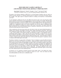
ISO 9001 ed 2000
Certificato n° 229
M.M.T. srl 26010 CAPRALBA (CR) - ITALY - Via degli Artigiani 56 tel. +39 0373 450595
www.mmtitalia.com
e-mail: [email protected]
ISO 9001 ed 2000
Certificato n° 229
fax. +39 0373 450728
395_E_man Rev. 1 del 14.03.2005
INSTRUCTION
www.mmtitalia.com
e-mail: [email protected]
fax. +39 0373 450728
395_E_man Rev. 1 del 14.03.2005
MANUAL - English
4 - Installation and use
For a correct installation follows the 3 following phases:
- determination of the electrode length
- fixing the electrode-holder on the boiler
- electric connection
Ceramic single electrode-holder - series 395
Code:
M.M.T. srl 26010 CAPRALBA (CR) - ITALY - Via degli Artigiani 56 tel. +39 0373 450595
395-000-00 and 395-001-00
Thank you for purchasing ceramic single electrode-holder series 395.
Before using the device, please read carefully this manual, and keep it in a safe place, for future
use.
1 - Description
The electrode-holder series 395 allows ON/OFF monitoring of level for conductive liquid.
They are particularly useful in boilers and steam generators.
The level switches to be used together with the electrode-holder series 395, are all of our
products of the series 200 and 201 (delayed).
The electrode is in stainless steel; the isolation is in ceramics (Al2O3).
2 - Technical characteristics
- thread: 3/8" or 1/2" gas
- protection grade: IP40
- electrode diameter: 6 mm
- electrode length: 1000 mm (optional)
- maximum temperature at the electrode: 250 °C
- maximum pressure: 25 bar
- weight: 100 g
4.1 The boiler has to be depressurize and vented to atmosphere, before the installation of the
electrode-holder.
Every operation on the electrode-holder must be performed only by qualified staff and always
with boiler depressurize and cold.
4.2 Determination of the length of the electrode
First of all, it is necessary d
ecide the electrode length, according to the desired water level, keeping in mind thread and
junction length.
The switching point is at the lower end of the electrode.
Once the length is decided, proceeds to the electrode cut.
The electrode must be mechanically assembled to the electrode-holder as in the following
drawing:
3 – Mechanical dimension
Fig.2
First, lock the electrode to the cylinder; then grip the cylinder with pliers, and tighten the
electrode with others pliers.
Then lock the nut to the cylinder: grip the cylinder with pliers, then tighten the nut with a
wrench.
Don't rotate absolutely the threaded electrode and the electrode in the electrode-holder.
4.3 Installing of the electrode-holder
The electrode-holder series 395 must be vertically assembled on the boiler, through a threaded
3/8" or ½” hole.
Fig.1
pag. 1/4
pag. 2/4
ISO 9001 ed 2000
Certificato n° 229
M.M.T. srl 26010 CAPRALBA (CR) - ITALY - Via degli Artigiani 56 tel. +39 0373 450595
www.mmtitalia.com
e-mail: [email protected]
ISO 9001 ed 2000
Certificato n° 229
fax. +39 0373 450728
M.M.T. srl 26010 CAPRALBA (CR) - ITALY - Via degli Artigiani 56 tel. +39 0373 450595
www.mmtitalia.com
e-mail: [email protected]
395_E_man Rev. 1 del 14.03.2005
395_E_man Rev. 1 del 14.03.2005
The electrode doesn't have to touch the wall of the boiler or the protective tube in which it is
contained.
The electrode-holder must be handled with care; it doesn't have to suffer drop or impact.
A drop could break the internal ceramics, without notice by visual examination; in case of drop,
do not use the electrode-holder, but return it to MMT for a check/test.
For the assembling, refer to the following drawing:
For the electric connection refer to the following drawing:
fax. +39 0373 450728
Fig.4
Fig.3
The electrode-holder has to be screwed only acting on the hexagon SW24 with a special
wrench; put 5 turns of teflon ribbon on the thread of the probe, to make the necessary seal on
the boiler.
Don't absolutely act on the ring nut that is up the hexagon SW24, to avoid ceramics break.
5 Wiring connection
The higher end of the electrode-holder, is a electrode of stainless steel, 4 MA threaded with nut
in stainless steel.
pag. 3/4
It is possible to use either a male faston connector or a eyelet terminal with 4mm hole.
Lock them with a 4 MA nut.
Insert the terminal with the electric cable coaxially with the electrode, placing it on the first nut;
then screw a second 4 MA nut.
Lock the terminal among the 2 nuts: holding the lower, act with a wrench on the higher.
Don't absolutely rotate the threaded electrode.
The connection cable is according to the level switch used.
Using our 200 and 201 series level switches, use cables, not necessarily screened, with section
larger than 1 mmq. The cables must not be channel together with power cables.
The cable length depends on the type of level switch used.
For switch with a.c. power supply (for standard and low sensibility), and for those with d.c.
power supply (for all sensibility), the cables can be long up to 200 m. For the switch with a.c.
power supply (for high sensibility), the cables have to be the shortest possible; in the range
1÷20 µS maximum length is 40 m; in the range 0.3÷2 µS, maximum length is 10 ms.
6 – Warning
The boiler has to be depressurize and vented to atmosphere before the installation of the
electrode-holder.
Every operation on the electrode-holder must have performed only by qualified staff and always
with boiler depressurize and cold.
The electrode doesn't have to touch the wall of the boiler or the protective tube in which it is
contained.
Don't turn the electrode in the probe.
pag. 4/4


© Copyright 2026