
Sony VAIO VPCEH Series Service Manual
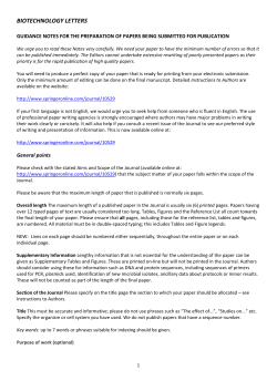
VPCEH Series SERVICE MANUAL Ver 1-2011E Revision History Model List S y on n o C e d i f l a i t n z Design and specifications are subject to change without notice. • ᧄᯏߩ᭽߅ࠃ߮ᄖⷰߪޔᡷ⦟ߩߚ੍๔ߥߊ ᄌᦝߔࠆߎߣ߇ࠅ߹ߔ߇ੌߏޔᛚߊߛߐޕ PERSONAL COMPUTER 9-890-843-01 Information in this document is subject to change without notice. Sony, VAIO and CLIE are trademarks or registered trademarks of Sony. Microsoft, Windows, Windows Media, Outlook, Bookshelf and other Microsoft products are trademarks or registered trademarks of Microsoft Corporation in the United States and other countries. The word Bluetooth and the Bluetooth logo are trademarks of Bluetooth SIG, Inc. AMD, the AMD logo, other AMD product names and combinations thereof are trademarks of Advanced Micro Devices, Inc. Intel Inside logo, Pentium, Celeron and Core are trademarks or registered trademarks of Intel Corporation. Transmeta, the Transmeta logo, Crusoe Processor, the Crusoe logo and combinations thereof are trademarks of Transmeta Corporation in the USA and other countries. Graffiti, HotSync, PalmModem, and Palm OS are registered trademarks, and the Hotsync logo and Palm are trademarks of Palm, Inc. or its subsidiaries. (M) and Motrola are trademarks of Motrora, Inc. Other Motrola products and services with (R) mark like Dragonball are the trademarks of Motrola, Inc. All other names of systems, products and services in this manual are trademarks or registered trademarks of their respective owners. In this manual, the (TM) or (R) mark are not specified. Caution Markings for Lithium/Ion Battery - The following or similar texts shall be provided on battery pack of equipment or in both the operating and the service instructions. Service and Inspection Precautions 1. Obey precautionary markings and instructions CAUTION: Danger of explosion if battery is incorrectly replaced. Replace only with the same or equivalent type recommended by the manufacturer. Discard used batteries according to the manufacturer’s instructions. CAUTION: The battery pack used in this device may present a fire or chemical burn hazard if mistreated. Do not disassemble, heat above 60°C (140°F) or incinerate. Dispose of used battery promptly. Keep away from children. Labels and stamps on the cabinet, chassis, and components identify areas requiring special precautions. Be sure to observe these precautions, as well as all precautions listed in the operating manual and other associated documents. After servicing, inspect to make sure that all screws, components, and wiring have been returned to their original condition. Also check the area around the repair location to ensure that repair work has caused no damage, and confirm safety. 2. Use designated parts only 5. When replacing chip components... The set’s components possess important safety characteristics, such as noncombustibility and the ability to tolerate large voltages. Be sure that replacement parts possess the same safety characteristics as the originals. Also remember that the mark, which appears in circuit diagrams and parts lists, denotes components that have particularly important safety functions; be extra sure to use only the designated components. CAUTION: Changing the back up battery. z Overcharging, short circuiting, reverse charging, multilation or incineration of the cells must be avoided to prevent one or more of the following occurrences; release of toxic materials, release of hydrogen and/or oxygen gas, rise in surface temperature. z If a cell has leaked or vented, it should be replaced immediately while avoiding to touch it without any protection. 3. Always follow the original design when mounting parts and routing wires The original layout includes various safety features, such as inclusion of insulating materials (tubes and tape) and the mounting of parts above the printer board. In addition, internal wiring has been routed and clamped so as to keep it away from hot or high-voltage parts. When mounting parts or routing wires, therefore, be sure to duplicate the original layout. The components identified by mark contain confidential information. Strictly follow the instructions whenever the components are repaired and/or replaced. 4. Inspect after completing service Never reuse components. Also remember that the negative side of tantalum capacitors is easily damaged by heat. 6. When handling flexible print boards... z z z The temperature of the soldering-iron tip should be about 270°C. Do not apply the tip more than three times to the same pattern. Handle patterns with care; never apply force. Caution: Remember that hard disk drives are easily damaged by vibration. Always handle with care. ATTETION AU COMPOSANT AYANT RAPPORT À LA SÉCURITÉ! LES COMPOSANTS IDENTIFÉS PAR UNE MARQUE SUR LES DIAGRAMMES SCHÉMATIQUES ET LA LISTE DES PIÈCES SONT CRITIQUES POUR LA SÉCURITÉ DE FONCTIONNEMENT. NE REMPLACER CES COMPOSANTS QUE PAR DES PIÈSES SONY DONT LES NUMÉROS SONT DONNÉSDANS CE MANUEL OU DANS LES SUPPÉMENTS PUBLIÉS PAR SONY. Sony Confidential -2- VPCEH Series (9-890-843-XX) Model List Area US (United States) Lineup VPCEH11FX/B VPCEH11FX/L VPCEH11FX/P VPCEH11FX/W VPCEH12FX/B VPCEH12FX/L VPCEH12FX/P VPCEH12FX/W VPCEH13FX/B VPCEH13FX/L VPCEH13FX/P VPCEH13FX/W VPCEH14FM/B VPCEH14FM/L VPCEH14FM/P VPCEH14FM/W VPCEH15FX/B VPCEH15FX/L VPCEH15FX/P VPCEH15FX/W VPCEH16FX/B VPCEH16FX/L VPCEH16FX/P VPCEH16FX/W VPCEH17FX/B VPCEH17FX/L VPCEH17FX/P VPCEH17FX/W VPCEH18GM/B VPCEH190X∗ VPCEH1AFX/B Area PA (Pan-America) Lineup Area VPCEH10EB/W VPCEH13FD/B VPCEH13FD/W VPCEH15FD/B VPCEH15FD/L VPCEH15FD/P VPCEH15FD/W VPCEH17FD/B VPCEH17FD/L VPCEH17FD/P VPCEH17FD/W EU (Europe) Lineup VPCEH1C5E∗ VPCEH1E1E/B VPCEH1E1E/L VPCEH1E1E/W VPCEH1E1R/B VPCEH1E1R/W VPCEH1J1E/B VPCEH1J1E/L VPCEH1J1E/W VPCEH1J8E/B VPCEH1J8E/W VPCEH1L0E/B VPCEH1L0E/L VPCEH1L0E/W VPCEH1L1R/B VPCEH1L1R/L VPCEH1L1R/W VPCEH1L8E/B VPCEH1L8E/P VPCEH1L8E/W VPCEH1L9E/B VPCEH1M0E/L VPCEH1M1E/B VPCEH1M1E/L VPCEH1M1E/W VPCEH1M1R/B VPCEH1M1R/W VPCEH1M8E/B VPCEH1M8E/L VPCEH1M8E/W VPCEH1M9E/B VPCEH1M9R/B VPCEH1S0E/B VPCEH1S0E/L VPCEH1S0E/W VPCEH1S1E/B VPCEH1S1E/L VPCEH1S1E/W VPCEH1S1R/B VPCEH1S1R/W VPCEH1S8E/B VPCEH1S8E/W VPCEH1S9E/B VPCEH1Z1E/B VPCEH1Z1E/L VPCEH1Z1R/B VPCEH1Z8E/B VPCEH1Z8E/L Area AP (Asia-Pacific) Lineup VPCEH15EG/B VPCEH15EG/W VPCEH15EN/B VPCEH15EN/W VPCEH16EA/B VPCEH16EA/P VPCEH16EA/W VPCEH16EF/B VPCEH16EG/B VPCEH16EG/P VPCEH16EG/W VPCEH16EH/B VPCEH16EH/W VPCEH16EN/B VPCEH16EN/W VPCEH17FG/B VPCEH17FG/L VPCEH17FG/P VPCEH17FG/W VPCEH17FK/W VPCEH18FA/B VPCEH18FA/W VPCEH18FF/B VPCEH18FG/B VPCEH18FG/L VPCEH18FG/P VPCEH18FG/W VPCEH18FH/B VPCEH18FH/P VPCEH18FH/W VPCEH18FK/B VPCEH18FK/P VPCEH18FK/W VPCEH18FW/B VPCEH18FW/P VPCEH18FW/W ∗: CTO Model Sony Confidential -3- VPCEH Series (9-890-843-XX) TABLE OF CONTENTS Section Title Page CHAPTER 1. BLOCK DIAGRAM .............................................................................................. 1-1 (to 1-1) CHAPTER 2. FRAME HARNESS DIAGRAM ................................................................. 2-1 (to 2-1) CHAPTER 3. EXPLODED VIEWS AND PARTS LIST Note ............................................................................................................................................................ 3-2 Main Section MS-1 ...................................................................................................................................................... 3-3 LCD L-1 .......................................................................................................................................................... 3-4 Accessories A-1 ......................................................................................................................................................... 3-5 (to 3-5) CHAPTER 4. OTHERS 4-1. Replacing the CPU .............................................................................................................................. 4-1 4-2. Note for WiMAX Board Replacement ............................................................................................... 4-2 (to 4-2) SPECIFICATIONS are listed on Page 3-1 of "CHAPTER 3. EXPLODED VIEWS AND PARTS LIST". History of the changes is shown as the"Revision History" at the end of this data. 䊶 㪪㪧㪜㪚㪠㪝㪠㪚㪘㪫㪠㪦㪥㪪䈲䇮㩹㪚㪟㪘㪧㪫㪜㪩㩷㪊㪅㩷㪜㪯㪧㪣㪦㪛㪜㪛㩷㪭㪠㪜㪮㪪㩷 㪘㪥㪛㩷㪧㪘㪩㪫㪪㩷㪣㪠㪪㪫㩹䈱㪊㪄㪈䊕䊷䉳䈮ឝタ䈘䉏䈩䈇䉁䈜䇯 䊶 ᄌᦝጁᱧ䈲䇮㵰㩷㪩㪼㫍㫀㫊㫀㫆㫅㩷㪟㫀㫊㫋㫆㫉㫐㩷㵱㩷䈫䈚䈩䇮ᧄ䊂䊷䉺ᧃ䈮 ⸥タ䈚䈩䈅䉍䉁䈜䇯 Sony Confidential -4- VPCEH Series (9-890-843-XX) CHAPTER 1. BLOCK DIAGRAM intel SandyBridge DDR SYSTEM MEMORY 1066/1333 MHz DMI 2.7GT/s Camera PORT4 FDI HDD SATA0 SATA Gen3 WiMax PORT9 X4 5GT/s INT_CRT DMI intel <PCH> ODD SATA3 Package type GB1b-64 DMI FDI PORT5 1GB / 512MB N12M-GS2/N12P-GV (37.5mm X 37.5mm) FDI Bluetooth 5GT/s VRAM NVIDIA PCIE rPGA 988 iGFX Interfaces Dual Channel DDR III PCI-E X16 SATA Gen2 INT_LVDS INT_HDMI USB I/O PORT0 USB I/O CougarPoint 0.7 USB 5GT/s PCI-Express Gen2 PCIE6 PORT2 USB I/O PORT3 PCIE4 USB 2.0 USB I/O PCIE1 PORT1 mBGA 989 (25mm X 25mm) Giga-LAN LPC SPI ROM DMIC 4MB SPK MIC Jack HP Jack WLAN/Widi/BT BT Combo : Atheros WB195 WiMAX : Kelsey Peak KSP(612BNXHWG) 802.11bgn/Intel/KsP_1x2_BBY SD-XC SPI CX20671 RTS5209 MS HDA Azalia RJ45 Audio CODEC Card Reader RTL8111E SPI ROM 2MB EC Wireless Switch NPCE791L/NPCE795L Touch Pad Power LED Button Sleep LED QWA# SATA LED VAIO# Battery LED ASSIST# RF LED Power SW SCROLED Keyboard CAPSLED NUMLED CARD LED 1-1 (END) Sony Confidential VPCEH Series (9-890-843-XX) L Side BATTERY PACK LCD CABLE ASSY ASSIST VAIO POWER SW BOARD Side B Bottom DC CABLE ASSY (L) R Side (R) SPK MODULE ASSY FFC MB-PS KEY BOARD UNIT MAIN BOARD Side A ODD CPU FAN ASSY Bottom HDD WLAN & WiMAX / WLAN ANT 1 2 FFC MB-TP WIRELESS LAN, WLAN/WiMAX COMBO, WLAN/BT COMBO CARD USB Board Side B From board to connector (direct connection) Harness (connector at both end) Harness (soldered at one end) Top SD CARD Front FFC MB-USB BLK GRY BATTERY MEMORY STICK 19.5V WEB MEMORY CAMERA MODULE Top Bottom MIC Memory x2 Model LCD UNIT MEMORY Front Bottom CHAPTER 2. FRAME HARNESS DIAGRAM PRO Duo SD ၮ᧼߆ࠄࠦࡀࠢ࠲߳㧔࠳ࠗࠢ࠻ធ⛯㧕 LEFT BUTTON RIGHT BUTTON WIRELESS OFF ON ࡂࡀࠬ㧔ਔ┵߇ࠦࡀࠢ࠲ઃ߈㧕 TOUCH PAD ࡂࡀࠬ㧔৻ᣇ߇ඨ↰ઃߌ㧕 Sony Confidential 2-1 (END) VPCEH Series (9-890-843-XX) CHAPTER 3. EXPLODED VIEWS AND PARTS LIST • The exploded views and parts list are compiled by blocks. The sections are different depending on the model. Please refer to list of contents shown on next page. • ಽ⸃࿑䈫ㇱຠ䈲㪃㩷䊑䊨䉾䉪䈗䈫䈮ಽ䈎䉏䈩䈇䉁䈜䇯 ᯏ⒳䈮䉋䈦䈩䉶䉪䉲䊢䊮䈏⇣䈭䉍䉁䈜䈱䈪㪃㩷⚦䈲ᰴ䊕䊷䉳䈱৻ⷩ䉕ෳ ᾖ䈚䈩䈒䈣䈘䈇䇯 Section LCD Page Note ................................................................................... 3-2 Main Section MS-1 ......................................................................... 3-3 LCD L-1 ............................................................................ 3-4 Accessories Main Section A-1 ............................................................................ 3-5 Sony Confidential 3-1 VPCEH Series (9-890-843-XX) • Double-click on the paper clip mark in the Spec column to open the specifications list. 䊶㩷㪪㫇㪼㪺ᰣ䈱䉪䊥䉾䊒䊙䊷䉪䉕䉻䊑䊦䉪䊥䉾䉪䈜䉎䈫䇮䉴䊕䉾䉪䈏㐿䈐䉁䈜䇯 • To open the specifications list, Microsoft office Excel or Excel viewer is required. 䊶㩷䉴䊕䉾䉪䉕㐿䈒䈢䉄䈮䈲㩷㪤㫀㪺㫉㫆㫊㫆㪽㫋㩷㪦㪽㪽㫀㪺㪼㩷㪜㫏㪺㪼㫃㩷䉁䈢䈲㩷㪜㫏㪺㪼㫃㩷䊎䊠䊷䊪䊷䈏ᔅⷐ䈮䈭䉍䉁䈜䇯 EH11FX/B EH11FX/L EH11FX/P EH11FX/W EH13FX/B EH13FX/L EH13FX/P EH13FX/W EH15FX/B EH15FX/L EH15FX/P EH15FX/W EH14FM/B EH14FM/L EH14FM/P U S EH14FM/W EH16FX/B EH16FX/L EH16FX/P EH16FX/W EH17FX/B EH17FX/L EH17FX/P EH17FX/W EH18GM/B EH12FX/B EH12FX/L EH12FX/P EH12FX/W EH1AFX/B EH190X∗ Main Section MS-1 MS-1 MS-1 MS-1 L-1 L-1 L-1 L-1 LCD Accessories A-1 A-1 A-1 A-1 MS-1 MS-1 MS-1 MS-1 MS-1 MS-1 MS-1 MS-1 MS-1 MS-1 MS-1 MS-1 MS-1 MS-1 MS-1 MS-1 MS-1 MS-1 MS-1 MS-1 MS-1 MS-1 MS-1 MS-1 MS-1 MS-1 MS-1 L-1 L-1 L-1 L-1 L-1 L-1 L-1 L-1 L-1 L-1 L-1 L-1 L-1 L-1 L-1 L-1 L-1 L-1 L-1 L-1 L-1 L-1 L-1 L-1 L-1 L-1 L-1 A-1 A-1 A-1 A-1 A-1 A-1 A-1 A-1 A-1 A-1 A-1 A-1 A-1 A-1 A-1 A-1 A-1 A-1 A-1 A-1 A-1 A-1 A-1 A-1 A-1 A-1 A-1 Spec EH17FD/B EH17FD/L EH17FD/P EH17FD/W EH15FD/B PA EH15FD/L EH15FD/P EH15FD/W EH13FD/B EH13FD/W EH10EB/W Main Section MS-1 MS-1 MS-1 MS-1 MS-1 MS-1 MS-1 MS-1 MS-1 MS-1 MS-1 LCD L-1 L-1 L-1 L-1 L-1 L-1 L-1 L-1 L-1 L-1 L-1 Accessories A-1 A-1 A-1 A-1 A-1 A-1 A-1 A-1 A-1 A-1 A-1 Spec EH1S1E/B EH1S1E/L EH1S1E/W EH1M8E/B EH1M8E/L EH1M8E/W EH1M1E/B EH1M1E/L EH1M1E/W EH1L0E/B EH1L0E/L EH1L0E/W EH1S1R/B EH1S1R/W EH1M1R/B EH1M1R/W EH1L1R/B EH1L1R/L EH1L1R/W EH1M9E/B EH1L9E/B EH1M9R/B EH1J1E/B E U EH1J1E/L EH1J1E/W EH1E1R/B EH1E1R/W EH1E1E/B EH1E1E/L EH1E1E/W EH1S9E/B EH1Z1R/B EH1Z8E/B EH1Z8E/L EH1M0E/L EH1L8E/B EH1L8E/P EH1L8E/W EH1J8E/B EH1J8E/W EH1Z1E/B EH1Z1E/L EH1S8E/B EH1S8E/W EH1S0E/B EH1S0E/L EH1S0E/W EH1C5E∗ Main Section MS-1 MS-1 MS-1 MS-1 MS-1 MS-1 MS-1 MS-1 MS-1 MS-1 MS-1 MS-1 MS-1 MS-1 MS-1 MS-1 MS-1 MS-1 MS-1 MS-1 MS-1 MS-1 MS-1 MS-1 MS-1 MS-1 MS-1 MS-1 MS-1 MS-1 MS-1 MS-1 MS-1 MS-1 MS-1 MS-1 MS-1 MS-1 MS-1 MS-1 MS-1 MS-1 MS-1 MS-1 MS-1 MS-1 MS-1 MS-1 LCD L-1 L-1 L-1 L-1 L-1 L-1 L-1 L-1 L-1 L-1 L-1 L-1 L-1 L-1 L-1 L-1 L-1 L-1 L-1 L-1 L-1 L-1 L-1 L-1 L-1 L-1 L-1 L-1 L-1 L-1 L-1 L-1 L-1 L-1 L-1 L-1 L-1 L-1 L-1 L-1 L-1 L-1 L-1 L-1 L-1 L-1 L-1 L-1 Accessories A-1 A-1 A-1 A-1 A-1 A-1 A-1 A-1 A-1 A-1 A-1 A-1 A-1 A-1 A-1 A-1 A-1 A-1 A-1 A-1 A-1 A-1 A-1 A-1 A-1 A-1 A-1 A-1 A-1 A-1 A-1 A-1 A-1 A-1 A-1 A-1 A-1 A-1 A-1 A-1 A-1 A-1 A-1 A-1 A-1 A-1 A-1 A-1 Spec EH18FG/P EH18FG/B EH18FG/L EH18FG/W EH18FH/B EH18FH/P EH18FH/W EH18FF/B EH18FK/B EH18FK/P EH18FK/W EH18FA/B EH18FA/W EH18FW/B EH18FW/P EH18FW/W EH17FG/B EH17FG/L AP EH17FG/P EH17FG/W EH17FK/W EH16EN/B EH16EN/W EH16EG/B EH16EG/P EH16EG/W EH16EH/B EH16EH/W EH16EF/B EH16EA/B EH16EA/P EH16EA/W EH15EN/B EH15EN/W EH15EG/B EH15EG/W Main Section MS-1 MS-1 MS-1 MS-1 L-1 L-1 L-1 L-1 LCD Accessories A-1 A-1 A-1 A-1 MS-1 MS-1 MS-1 MS-1 MS-1 MS-1 MS-1 MS-1 MS-1 MS-1 MS-1 MS-1 MS-1 MS-1 MS-1 MS-1 MS-1 MS-1 MS-1 MS-1 MS-1 MS-1 MS-1 MS-1 MS-1 MS-1 MS-1 MS-1 MS-1 MS-1 MS-1 MS-1 L-1 L-1 L-1 L-1 L-1 L-1 L-1 L-1 L-1 L-1 L-1 L-1 L-1 L-1 L-1 L-1 L-1 L-1 L-1 L-1 L-1 L-1 L-1 L-1 L-1 L-1 L-1 L-1 L-1 L-1 L-1 L-1 A-1 A-1 A-1 A-1 A-1 A-1 A-1 A-1 A-1 A-1 A-1 A-1 A-1 A-1 A-1 A-1 A-1 A-1 A-1 A-1 A-1 A-1 A-1 A-1 A-1 A-1 A-1 A-1 A-1 A-1 A-1 A-1 Spec ∗: CTO Model Sony Confidential 3-1 (a) VPCEH Series (9-890-843-XX) Note Parts List is attached on the upper right portion of each EXPLODED VIEW. Items marked “ * “ are not stocked since they are seldom required for routine service. Some delay should be anticipated when ordering these items. The parts marked “ $ “ are the Reuse Parts. The parts marked with "&" indicates specific parts handling for Japan region. ˴Disregard "&" marking for other than Japan region. Color after discription in [ ] shows color variation name of the main body. The model that is accompanied asterisk (∗) is the CTO model. Description of [***MBx2], [***MB], [***GBx2], [***GB]indicates the following. ***MB/***GB: size of the part x2: installed quantity at original production Be sure to use the parts marked with x/sx together with the parts with the same number. When replacing the HDD of RAID setting, please exchange to the same HDD that was installed. If there is the Remarks column in the parts list, the features of applicable models are indicated in it for the parts that are different depending on each model. For the abbreviations used in the remarks column, please refer to the <table 1>. 䊶ㇱຠ䈮㪩㪼㫄㪸㫉㫂㫊ᰣ䈏䈅䉎႐ว㪃㩷䈇ಽ䈔䈏↢䈛䉎ㇱຠ䈮䈧䈇䈩㪃㩷್䈱⋡䈫䈭䉎ኻᔕ䊝䊂䊦䈱․ᓽ䉕 ␜䈚䈩䈇䉁䈜䇯 ⸥ㅀ䈱⋭⇛ᣇᴺ䈮䈧䈇䈩䈲㪓㫋㪸㪹㫃㪼㩷㪈㪕䉕ෳᾖ䈒䈣䈘䈇䇯 <table 1> Full-Name Basically, the parts marked “” should be used for service. The parts marked “” in the parts list are substitution parts. If the part marked “” is not available, you can order the parts marked “”, but it may not be stocked. The components identified by mark ! or dotted line with mark ! are critical for safety. Replace only with part number specified. ㇱຠ䈲㪃㩷ฦಽ⸃࿑䈱ฝㇱ䈮ᷝઃ䈘䉏䈩䈇䉁䈜䇯 * ශ䈱ㇱຠ䈲Ᏹᐶ䈚䈩䈍䉍䉁䈞䉖䇯 ㇱຠฬ⒓䈱೨䈮㩻ශ䈱䈧䈇䈢ㇱຠ䈲㪃㩷㪩㪼㫌㫊㪼㩷㪧㪸㫉㫋㫊䈪䈜䇯 ㇱຠฬ⒓䈱೨䈮㩽ශ䈱䈧䈇䈢ㇱຠ䈲㪃㩷䈍ቴ᭽䈪䉅឵น⢻䈭㪚㫌㫊㫋㫆㫄㪼㫉㩷㪩㪼㫇㫃㪸㪺㪸㪹㫃㪼㩷㪧㪸㫉㫋㫊 㩿㪚㪩㪧㪀䈪䈅䉍㪃㩷⽼ᄁน⢻䈪䈜䇯 ․䈮㪓㩽㪕ශ䈱䈧䈇䈢ㇱຠ䈲㪃㩷䈇ಽ䈔䈏ᔅⷐ䈭ㇱຠ䈪䈜䈱䈪㪃㩷ᔅ䈝ಽ⸃࿑䈪ኻ⽎ㇱຠ䉕 䈗⏕䈒䈣䈘䈇䇯 ㇱຠฬ⒓䈱ᓟ䈮㪲㩷㪴䈪⦡䈏␜䈘䉏䈩䈇䉎႐ว㪃㩷㪙㫆㪻㫐䈱䉦䊤䊷䊋䊥䉣䊷䉲䊢䊮ฬ⒓䉕䉒䈚䈩 䈇䉁䈜䇯 ᯏ⒳ฬ䈮䋨㪁䋩䈏䈧䈒䉅䈱䈲㪚㪫㪦䊝䊂䊦䈪䈜䇯 ㇱຠฬ䈱㪲㪁㪁㪁㪤㪙x㪉㪴㪃㩷㪲㪁㪁㪁㪤㪙㪴㪃㩷㪲㪁㪁㪁㪞㪙x㪉㪴㪃㩷㪲㪁㪁㪁㪞㪙㪴㩷╬䇱䈲એਅ䉕䉒䈚䈩䈇䉁䈜䇯 㪁㪁㪁㪤㪙㪆㪁㪁㪁㪞㪙㪑㩷䈖䈱ㇱຠ䈱ኈ㊂ 㵘㵘㩷㩷㩷㩷㩷㩷㩷㩷㩷㩷㩷㩷㩷㩷㩷x㪉㪑㩷⩄ᤨ䈮タ䈘䉏䈩䈇䉎ຬᢙ x/sx䈮䈭䈦䈩䈇䉎ㇱຠ䈲㪃㩷ห䈛ᢙሼ䈬䈉䈚䈪ᔅ䈝৻✜䈮↪䈚䈩䈒䈣䈘䈇䇯 㪩㪘㪠㪛⸳ቯ䈱㪟㪛㪛䉕឵䈜䉎㓙䈲㪃㩷タ䈘䉏䈩䈇䈢㪟㪛㪛䈫ห䈛䉅䈱䈮឵䈚䈩䈒䈣䈘䈇䇯 BT Felica Felica Wireless WAN WAN Wireless LAN WLAN 1 1seg Tuner 1 1seg Finger Print Sensor FP Security Chip TPM Les composants identifiés par une marque ! sont critiques pour la sécurité. Ne les remplacer que par une pièce portant le numéro spécifié. The components identified by mark contain confidential information. Strictly follow the instructions whenever the components are repaired and/or replaced. Short-Name Bluetooth Flash Memory SSD Camera Camera Touchscreen Panel Touchscreen Transfer Jet T-Jet If "No-" is described on the left side of the Short-Name, it means 'not equipped'. Example: "No-BT" "No-Felica” etc. When several descriptions are listed, each description is separated with “, (comma)" or " or". "Comma" means plus. Example.1: The parts for the model equipped with BT and Felica and WLAN 㸢 BT, Felica, WLAN Example.2: The parts for the model equipped with BT or Felica 㸢 BT or Felica If the color is in the remarks column, it indicates the color of parts itself. 䊶䇸ή䈚䇹䉕䈜䉎႐ว䈮䈲㪃㩷㪪㪿㫆㫉㫋㪄㪥㪸㫄㪼䈱Ꮐ䈮䇸㪥㫆㪄䇹䈫䈧䈔䉁䈜䇯㩷 㪀䇸㪥㫆㪄㪙㪫䇹䇸㪥㫆㪄㪝㪼㫃㫀㪺㪸䇹䈭䈬 䊶ᵈ⸥䉕ⶄᢙ⸥タ䈜䉎㓙䈮䈲䇸㪃㩿䉦䊮䊙㪀䇹䈲䇸㫆㫉䇹䈪ಾ䉍䉁䈜䇯䇸㪃䋨䉦䊮䊙䋩䇹䈲䊒䊤䉴䈫䈇䈉ᗧ䈫䈚䈩䈇䉁䈜䇯 㪈㪀㩷㪙㪫䈫㪝㪼㫃㫀㪺㪸䈫㪮㪣㪘㪥䈏タ䈘䉏䈢䊝䊂䊦䈮䈧䈒ㇱຠ㩷㸢㩷㪙㪫㪃㩷㪝㪼㫃㫀㪺㪸㪃㩷㪮㪣㪘㪥㩷 㪉㪀㩷㪙㪫タ䊝䊂䊦䈲㪝㪼㫃㫀㪺㪸タ䊝䊂䊦䈮䈧䈒ㇱຠ㩷㸢㩷㪙㪫㩷㫆㫉㩷㪝㪼㫃㫀㪺㪸 䊶⦡⸥䈱႐ว㪃㩷ᒰ䈱ㇱຠ⥄䈱⦡䉕␜䈚䉁䈜䇯 ㇱຠਛ㵰㵱䈱䈧䈇䈢ㇱຠ䈲㪃㩷ઍᦧㇱຠ䈪䈜䇯ၮᧄ䈲ශ 䈱ㇱຠ䉕↪䈚䈩䈒䈣䈘䈇䇯 ශ䈱ㇱຠ䈏ή䈇႐ว䈲㪃㩷ශ䈱ㇱຠ䉕䉥䊷䉻䊷䈜䉎䈖䈫䉅 น⢻䈪䈜䈏㪃㩷ᐶ䈘䉏䈩䈇䈭䈇႐ว䈏䈅䉍䉁䈜䇯 㩷㩸㩷ශ䈱ㇱຠ㪃㩷䉁䈢䈲㩷㩸㩷ශઃ䈐䈱ὐ✢䈪࿐䉁䉏䈢ㇱຠ 䈲㪃ోᕈ䉕⛽ᜬ䈜䉎䈢䉄䈮㊀ⷐ䈭ㇱຠ䈪䈜䇯ᓥ䈦䈩 ឵ᤨ䈲㪃㩷ᔅ䈝ᜰቯ䈱ㇱຠ䉕↪䈚䈩䈒䈣䈘䈇䇯 㩷㩷㩷ශ䈱ㇱຠ䈮䈲䋬⒁ኒᖱႎ䈏䉁䉏䈩䈇䉁䈜䇯㩷ୃℂ 䈱㓙䈲䋬ᜰ␜䈮ᓥ䈦䈢ኻᔕ䉕ⴕ䈭䈦䈩䈒䈣䈘䈇䇯㩷 Sony Confidential 3-2 VPCEH Series (9-890-843-XX) Parts List MS-1. Main Section 31 (2) Memory x 2 Model 6 4 (1) B1 B6 6 B D G B6 L-1 M • Double-click on the paper clip mark to open the parts list. 䊶㩷 䉪䊥䉾䊒䊙䊷䉪䉕䉻䊑䊦䉪䊥䉾䉪䈜䉎䈫䇮ㇱຠ䈏㐿䈐䉁䈜䇯 B5 External 31 Model (2) A 1) When change the CPU (Ref. No. 4), refer to " Replacing the CPU " in CHAPTER 4. B5 5 (3) I L-1 K •To open the parts list, Microsoft office Excel or Excel viewer is required. 䊶ㇱຠ䉕㐿䈒䈢䉄䈮䈲㩷㪤㫀㪺㫉㫆㫊㫆㪽㫋㩷㪦㪽㪽㫀㪺㪼㩷㪜㫏㪺㪼㫃㩷䉁䈢䈲㩷㪜㫏㪺㪼㫃㩷䊎䊠䊷䊪䊷䈏ᔅⷐ䈮䈭䉍䉁䈜䇯 9 L-1 L D 1) 㪚㪧㪬㩷㩿㪩㪼㪽㪅㩷㪥㫆㪅㩷㪋㪀㩷䉕឵䈜䉎㓙䈮䈲㪃㩷㪚㪟㪘㪧㪫㪜㪩㩷㪋㩷䈱 䇸㪩㪼㫇㫃㪸㪺㫀㫅㪾㩷㫋㪿㪼㩷㪚㪧㪬䇹䉕䈗ෳᾖ䈒䈣䈘䈇䇯 C 2) When heat sink is removed from CPU, clean off the thermal grease and put the Ref. No. 31. Internal Model B6 2) 䊍䊷䊃䉲䊮䉪䉕㪚㪧㪬䈎䉌ᄖ䈚䈢㓙䈲㪃㩷䉫䊥䉴䉕ข䉍㪃㩷㪩㪼㪽㪅㩷 㪥㫆㪅㩷㪊㪈㩷䉕ႣᏓ䈚䈩䈒䈣䈘䈇䇯 A E 3) When replacing the WiMAX board (Ref. 5), be sure to refer to “4-2. Note for WAN Board Replacement”. 1 10 27 B6 B6 B6 3 G C B B6 17 37 21 E F B1 14 10 B1 B6 B2 2 F 18 E E H I D B2 24 26 G 19 36 B1 7 15 B1 16 A L-1 K G L-1 I B1 30 F 20 C B3 B6 B4 B4 B1 29 B1 12 B1 3) 㪮㫀㪤㪘㪯ၮ᧼䋨㪩㪼㪽㪅㩷㪌䋩䉕឵䈜䉎㓙䈮䈲㪃㩷ᔅ䈝䇸㪋㪄㪉㪅㩷㪮㫀㪤㪘㪯 ၮ᧼឵ᤨ䈱ᵈᗧ䇹䉕ෳᾖ䈚䈩䈒䈣䈘䈇䇯 A C H B6 External Model 35 13 28 B3 F B4 25 38 22 B4 B4 D 11 3-3 8 23 B1 B B A Sony Confidential VPCEH Series (9-890-843-XX) Parts List L-1. LCD • Double-click on the paper clip mark to open the parts list. 䊶㩷 䉪䊥䉾䊒䊙䊷䉪䉕䉻䊑䊦䉪䊥䉾䉪䈜䉎䈫䇮ㇱຠ䈏㐿䈐䉁䈜䇯 •To open the parts list, Microsoft office Excel or Excel viewer is required. 䊶ㇱຠ䉕㐿䈒䈢䉄䈮䈲㩷㪤㫀㪺㫉㫆㫊㫆㪽㫋㩷㪦㪽㪽㫀㪺㪼㩷㪜㫏㪺㪼㫃㩷䉁䈢䈲㩷㪜㫏㪺㪼㫃㩷 䊎䊠䊷䊪䊷䈏ᔅⷐ䈮䈭䉍䉁䈜䇯 1010 B8 1004 1006 B7 MS-1 I 1001 B7 1008 B8 1010 H MS-1 K H B1 B1 MS-1 K 1014 1005 J B1 B7 B7 1007 B7 1011 1002 MS-1 L MS-1 M 1009 B7 B1 1013 1015 1012 B7 MS-1 J J 1013 B7 1003 1012 Sony Confidential 1011 B7 3-4 VPCEH Series (9-890-843-XX) Parts List A-1. Accessories • Double-click on the paper clip mark to open the parts list. 䊶㩷 䉪䊥䉾䊒䊙䊷䉪䉕䉻䊑䊦䉪䊥䉾䉪䈜䉎䈫䇮ㇱຠ䈏㐿䈐䉁䈜䇯 •To open the parts list, Microsoft office Excel or Excel viewer is required. 䊶ㇱຠ䉕㐿䈒䈢䉄䈮䈲㩷㪤㫀㪺㫉㫆㫊㫆㪽㫋㩷㪦㪽㪽㫀㪺㪼㩷㪜㫏㪺㪼㫃㩷䉁䈢䈲㩷㪜㫏㪺㪼㫃㩷䊎䊠䊷䊪䊷䈏ᔅⷐ䈮䈭䉍䉁䈜䇯 2001 2006 2011 2002 2007 2012 Power Cord Power-Supply Cord Set 2003 2008 2013 2004 2009 2014 2005 2010 2015 AC Adaptor Battery (VGP-BPS26) Battery (VGP-BPL26) Power Cord Set Power Cord Set Power Cord Set Power Supply Cord Set AC Power Cord Power Cord Set Power Cord Power-Supply Cord Power-Supply Cord Power-Supply Cord Sony Confidential 3-5 (END) VPCEH Series (9-890-843-XX) CHAPTER 4. OTHERS 4-1. Replacing the CPU 1. How to remove the CPU 1 Rotate the lock with a flat-blade screwdriver toward the unlock position shown in the figure. 2 Remove up the CPU. 1 CPU lock position 2 CPU socket unlock position 2. How to install the CPU 1 Position the mark on the CPU to the mark on the CPU socket and put in all pins to the holes on the CPU socket. 2 Pressing two corners marked with in the figure, rotate the lock with a flat-blade screwdriver toward the lock position. 2 mark mark CPU unlock position lock position mark 1 CPU socket Note: Lock the CPU properly, or operation becomes unstable. Sony Confidential 4-1 VPCEH Series (9-890-843-XX) 4-2. Note for WiMAX Board Replacement 4-2. WiMAXၮ᧼឵ᤨ䈱ᵈᗧ When replacing the WiMAX Board (Ref. 5 A-1835-561-A) change the barcode label on the bottom. 㪮㫀㪤㪘㪯ၮ᧼㩷㩿㪩㪼㪽㪅㩷㪌㩷㪘㪄㪈㪏㪊㪌㪄㪌㪍㪈㪄㪘㪀䉕឵䈚䈢㓙䈮䈲䇮䊗䊃䊛䈱䊋䊷䉮䊷䊄䊤䊔䊦䈱⾍䉍ᦧ䈋ᬺ䉕ⴕ䈦䈩䈒䈣䈘䈇䇯 Ԙ Peel off the barcode label which is attached to the bottom. (Refer to the figure below.) Ԙ ࡏ࠻ࡓߦ⾍ࠄࠇߡࠆࡃࠦ࠼ࡌ࡞ࠍߪ߇ߒ߹ߔޕ 㧔ਅ࿑ෳᾖ㧕 Ref. 5 A-1835-561-A WLAN/WiMAX COMBO CARD WiMAX : ∗∗∗∗∗∗∗∗∗∗∗∗ ԙ Attach the barcode label which is included with the WiMAX Board to the position where you peeled off the label in the step Ԙ. ԙ 9K/#: ၮ᧼ߦหᪿߐࠇߡࠆࡃࠦ࠼ࡌ࡞ࠍԘߢߪ߇ߒߚ⟎ߦ⾍ߞߡߊߛߐޕ Sony Confidential 4-2 (END) VPCEH Series (9-890-843-XX) VPCEH Series (US/PA/EU/AP) This manual and the constituent data may not be replicated, copied nor reprinted in whole or in part without prior written authorization of Sony Corporation. ᧄࡑ࠾ࡘࠕ࡞ߩ৻ㇱ㧘߹ߚߪోㇱߦߟߡ㧘ήᢿߢ ࠺࠲ߩⶄ㧘ⶄ౮㧘ォタߔࠆߎߣࠍߓ߹ߔޕ Sony Corporation 9-890-843-01 - 15 - English / Japanese 2011E2700-1 © 2011 Sony Corporation Published by Sony Corporation VAIO & Mobile Business Group CS & Quality Div. VAIO Global CS Dept. Revision History Suffix -01 Ver. Ver. 1 Date 2011.05.25 Contents First Edition QM No. - <Remarks> 473 [Sony Confidential] VPCEH Series (9-890-843-XX)


© Copyright 2026