
the rotary clothesline product
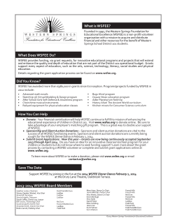
the
rotary
clothesline
product
manual
rotary 37 & 47
clotheslines
Introduction
It’s important that you read this Product
Manual thoroughly before installation to benefit
from the design features and enjoy safe use of
this product.
Step 2 – Install the Ground Socket
Part name
Qty.
Main standard
1
Head assembly
1
Ground socket with cover
1
Plastic spacers
3
Thank you for choosing Hills.
Step 1 – Select a Suitable
Location
Patents and Registered Designs apply to
this product.
1.1 Select a suitable area for installation.
Warning
• Do not allow children or pets to swing on
the clothesline or items of laundry.
• Ensure when raising and lowering your
clothesline that bystanders (in particular
children) are standing well clear.
• Do not use for any purpose other than to
hang and dry washing.
• Do not use your clothesline if parts are worn
or damaged.
2.3 Insert the main standard into the ground
socket. Engage the locking collar and lock
into position.
2.4 Place the ground socket and main standard
into the hole.
Push the base of the ground socket into
the gravel.
Main standard
Check level vertically.
500mm (1'7")
The top of the ground socket must sit
approximately 6-12mm (1/4"-1/2") above
ground level.
3.2m (10'6")
Rotary 37
2.5 Support the main standard and concrete
into position.
3.6m (11' 9")
Rotary 47
Concrete should be damp enough to ‘hold
together’ when squeezed in your hand.
500mm (1'7")
Close tabs to
prevent entry
of concrete
Locking collar
Top of socket
approximately
6-12mm (1/4"-1/2")
above ground level
Engage into
ground socket.
Rotate to lock.
Ground
socket
Settle concrete by pushing a thin stick into
the mix several times.
Leave the main standard in the ground
socket until the concrete has set.
Keep concrete out of the locking recess in
the ground socket.
2.6 Allow 24 hours for the concrete to set before
final assembly and use of your Rotary Hoist.
Please retain this Product Manual. Record the following
information for future reference.
Product Number (printed on carton):
Name and location of store:
Check for level
Make sure the tabs are closed to prevent
concrete entering the locking recess.
• Do not allow the frame to lower in an
uncontrolled manner as damage
or injury may result.
Date of purchase:
Fig. 2
2.2 Place approximately 200mm (8") of coarse
gravel into the hole.
1.2 Allow a minimum of 500mm (1'7")
clearance around your Rotary Hoist (Fig. 1).
Fig. 1
2.1 Dig a hole 250mm (10") diameter by
approximately 650mm (26") deep (Fig. 2).
®
Designed and tested under a
Quality System that meets Hills’
demanding quality specifications.
Made in China
250mm (10")
650mm (26")
Congratulations on the purchase of your Hills
Rotary Clothesline, which will bring you many
years of trouble free and efficient drying.
Carton Contents
450mm (18")
concrete
Congratulations
3
Installation
200mm (8")
gravel
2
4
Assembly
Step 3 – Assemble the Hoist
3.1
3
3.2 Place the bottom of the head assembly
into the top of the main standard and
lower it gently until it stops (Fig. 3).
6
5
Step 4 – Operating the Hoist
3.3 To engage, raise the head assembly by
approximately 100mm (4") and lower
until a ‘click’ is heard.
Place the main standard in the
ground socket.
4
7
4.1
3.4 Check the head assembly is locked in
position by lifting upwards (it should
not move). If the head assembly is not
engaged, repeat Step 3.3.
8
9
10
11
12
A
Note: There is a small amount of
rotational movement between the wind
brake and the lower cross latch.
This is normal.
Fig. 3
1
2
6
5
3
7
8
4
6
5
10
11
4.2 To open: Undo the line tie-off cord.
(Refer to Step 6). Make sure the lines
are tangle free. Push the lower cross and
arms up until the latch engages.
To adjust the height of your Rotary Hoist,
wind the handle and head assembly
down and then fit one or more of the
plastic spacers in the ground socket.
The suggested operating height is the
user’s head height +25mm (1") (Fig. 4).
4.3 To fold: Press the latch to release the
lower cross. Place your hands on the
arms and pull downwards.
4.4 Wrap and fasten the line tie-off cord
around the hoist to prevent lines from
becoming tangled.
Note: The height adjusting winding
mechanism has an automatic device to
disengage the handle at the maximum
and minimum heights.
A slight ‘clicking’ noise will be heard
when this system is operating.
B
7
8
Note: Once the head is engaged into the
main standard it cannot be removed.
9
A
ISSUE
1
12
REF.
9
10
11
REVISION
RELEA SED FOR A RTWORK
DATE
24.09.10
RFC
DWN.
PS
CHK.
12
APP.
4.5 To remove from the ground socket:
Unlock the locking collar by rotating
anti-clockwise. Lift the Rotary Hoist from
the ground socket and store in a suitable
place. Insert the cover into the top of the
ground socket.
A
A
Head
assembly
5
Operation
C
B
B
B
Fig. 4
D
GENERAL ASSEMBLY DETAILS
1.
ALL DIMENSIONS ARE EQUAL ABOUT CL UNLESS
OTHERWISE STATED.
2.
DIMENSIONS BOUNDED BY
ARE CRITICAL FOR
ASSEMBLY WITH OTHER COMPONENTS.
3.
THE DIMENSIONS SHOWN ON THIS DRAWING PLUS
THE 3D CAD DATACFULLY DEFINE THE FINISHED PART.
4.
ALL COMPONENTS TO BE CLEAN AND FREE FROM
SHARP EDGES, BURRS AND DEFECTS.
5.
IF IN DOUBT ASK
Insert head
FIG 3.
assembly
Wind FOLDED HEAD
ASSEMBLY
brake
D
DO NOT SCALE DRAWING.
DIMENSIONS IN MILLIMETRES.
Engage by
raising and
lowering head
assembly until a
‘click’ is heard
E
Third Angle
Projection.
GENERAL ASSEMBLY DETAILS
CL UNLESS
ALL DIMENSIONS ARE EQUAL ABOUT
Drawn:
P. Stevens
OTHERWISE STATED.
Checked: X. Xxxxxxxx
1.
Material:
ALL COMPONENTS TO BE CLEAN AND FREE FROM
Estimated Mass: 9534 (grams)
SHARP EDGES, BURRS AND DEFECTS.
5.
IF IN DOUBT ASK
Additives:
Home & Hardware Products
Unit H, 5 Butler
Boulevard
Description
Burbridge Business Park
Adelaide Airport
South Australia 5950
Copyright © 2010
TM
Project Number
H
FIG 3.
MAIN STANDARD ASSEMBLY
4
5
IF IN DOUBT ASK
Revision 4 - 09.02.10 - DHN
TM
Latch
DO NOT SCALE DRAWING.
DIMENSIONS IN MILLIMETRES.
Third Angle
Projection.
Drawing Number
FD88012
H
P. Stevens
Checked: X. Xxxxxxxx
Sheet 1 of 1
11
12
REFER TO INDIVIDUAL COMPONENTS
Date:
Appro ve d:
Da te :
Press to
release
G
Additives:
Estimated Mass: 9187
(grams)
Volume
Description
Project Number
EVERYDAY ROTARY 47
D423
Drawing Number
6
FD88012
H
7
8
9
10
Sheet
size
A2
Ground socket
EVERYDAY ROTARY 47
Drawing Number
FD88012
D423
SCALE:1:2
Issued / Received
H
Sheet 1 of 1
1
Issue:
11
Spacers
d leve
REFER TO DRAWING SPECIFICATION
MID MARKET ROTARY
MID MARKET ROTARY
Locking collar
Groun
1950432 (mm³)
Volume
Finish:
Project:
Project:
Cover
24.09.10
Date: XX.XX.XX
Drawn:
Estimated Mass: 9534
Colour:
F
GENERAL TOLERANCES:
Unless Otherwise Stated:
0 Dec. place 0.5mm
1 Dec. place 0.25mm
2 Dec. place 0.10mm
Holes: +0.25mm -0mm
Angles: 0.25
Material:
G
(grams)
2215249 (mm³)
REFER TO DRAWING SPECIFICATION
REFER TO COLOUR TABLE
E
Lower cross
REFER TO INDIVIDUAL COMPONENTS
1
Issue:
Home & Hardware Products
Unit H, 5 Butler Boulevard
Burbridge Business Park
Adelaide Airport
South Australia 5950
Copyright © 2010
REFER TO COLOUR TABLE
Project Number
3
5.
Colour:
Description
2
A2
Additives:
Finish:
1
D423
Date:
Approved:
Ground level
ALL COMPONENTS TO BE CLEAN AND FREE FROM
SHARP EDGES, BURRS AND DEFECTS.
Hills Industries Limited
EVERYDAY ROTARY 47
Issued / Received
Date: 22.09.10
10Date: XX.XX.XX
Drawn:
P. Stevens
9 Checked: X. Xxxxxxxx
Material:
4.
ABN 35 007 573 417
MID MARKET ROTARY
F
GENERAL TOLERANCES:
Unless Otherwise Stated:
0 Dec. place 0.5mm
1 Dec. Sheet
place 0.25mm
2 Dec. size
place 0.10mm SCALE:1:20
Holes: +0.25mm -0mm
Angles: 0.25
Third Angle
Projection.
8
THE DIMENSIONS SHOWN ON THIS DRAWING PLUS
THE 3D CAD DATA FULLY DEFINE THE FINISHED PART.
G
2215249 (mm³)
REFER TO DRAWING SPECIFICATION
REFER TO COLOUR TABLE
Colour:
Hills Industries
Limited
DO NOT SCALE DRAWING.
DIMENSIONS IN MILLIMETRES.
7
DIMENSIONS BOUNDED BY
ARE CRITICAL FOR
ASSEMBLY WITH OTHER COMPONENTS.
3.
Volume
Project:
6
E
2.
Finish:
ABN 35 007 573 417
5
22.09.10
XX.XX.XX
Date:
THE DIMENSIONS SHOWN ON THIS DRAWING PLUS
THE 3D CAD DATA FULLY DEFINE THE FINISHED PART.
ALL DIMENSIONS ARE EQUAL ABOUT CL UNLESS
OTHERWISE STATED.
1.
Latch detail
REFER TO INDIVIDUAL COMPONENTS
4.
F
Main
standard
GENERAL ASSEMBLY DETAILS
F
GENERAL TOLERANCES:
Unless Otherwise Stated:
0 Dec. place 0.5mm
1 Dec. place 0.25mm
2 Dec. place 0.10mm
Holes: +0.25mm -0mm
Angles: 0.25
Date:
3.
FIG 3.
MAIN STANDARD ASSEMBLY
Home & Hardware Products
Unit H, 5 Butler Boulevard
Burbridge Business Park
Adelaide Airport
South Australia 5950
Copyright © 2010
Date:
Approved:
DIMENSIONS BOUNDED BY
ARE CRITICAL FOR
ASSEMBLY WITH OTHER COMPONENTS.
2.
FIG 3.
LDED HEAD ASSEMBLY
G
D
ABN 35 007 573 417
TM
4
E
Hills Industries Limited
D
3
C
User's head height +25mm (1")
C
Revision 4 - 09.02.10 - DHN
Lower
cross
12
l
6
Line Tensioning
Line Tensioning
Step 5 – Tensioning the Lines
5.1 Insert the Rotary Hoist into the ground
socket, open up and lock into position
(Fig. 5).
5.2 If the whole clothesline needs to be
re-tensioned, start from the outside line
and work towards the centre.
2
3
Step 1
In either case, untie the PVC line from
the line tie off saddle on one side of
the arm only. Pull PVC line through one
clip at a time until line is taut. Re-tie
PVC line around tie off saddle. Trim off
any excess line if required. Push line
into the hole in the arm.
If over time, the line does need tensioning,
the Rotary Hoist must be in the open position.
1
Step 5 (continued)
If only a single line requires
re-tensioning, just re-tension
this particular line.
The lines are pre-tensioned in the factory.
No initial tensioning is required.
6
5
Step 2
Pull line out of arm.
Do not over tension the lines.
4
7
Remove line from under locking lip.
Step 3
7
8
ISSUE
1
REF.
9
Step 4
10
11
REVISION
RELEA SED FOR A RTWORK
DATE
22.09.10
RFC
DWN.
PS
CHK.
12
APP.
A
A
Fig. 5
6
7
8
ISSUE
1
REF.
9
10
11
REVISION
RELEA SED FOR A RTWORK
DATE
22.09.10
RFC
DWN.
PS
CHK.
12
APP.
A
Pull line out from tensioner.
B
B
Starting at the furthest arm from the tensioning arm,
pull the line tight and move from arm to arm to generate
desired line tension.
B
Step 5
C
Step 6
C
C
3
4
6
5
7
D
8
ISSUE
1
REF.
D
9
10
11
REVISION
RELEA SED FOR A RTWORK
DATE
22.09.10
RFC
DWN.
PS
CHK.
12
APP.
D
GENERAL ASSEMBLY DETAILS
1.
ALL DIMENSIONS ARE EQUAL ABOUT CL UNLESS
OTHERWISE STATED.
2.
DIMENSIONS BOUNDED BY
ARE CRITICAL FOR
ASSEMBLY WITH OTHER COMPONENTS.
3.
THE DIMENSIONS SHOWN ON THIS DRAWING PLUS
THE 3D CAD DATA FULLY DEFINE THE FINISHED PART.
4.
ALL COMPONENTS TO BE CLEAN AND FREE FROM
SHARP EDGES, BURRS AND DEFECTS.
5.
IF IN DOUBT ASK
A
E
Hills Industries Limited
E
ABN 35 007 573 417
TM
DO NOT SCALE DRAWING.
DIMENSIONS IN MILLIMETRES.
Third Angle
Projection.
Drawn:
Checked:
Appro ve d:
P. Stevens
X. Xxxxxxxx
Material:
F
B
Home & Hardware Products
Unit H, 5 Butler Boulevard
Burbridge Business Park
Adelaide Airport
South Australia 5950
Copyright © 2010
F
GENERAL TOLERANCES:
Unless Otherwise Stated:
0 Dec. place 0.5mm
1 Dec. place 0.25mm
2 Dec. place 0.10mm
Holes: +0.25mm -0mm
Angles: 0.25
Date:
Date:
Da te :
Tensioning arm
Revision 4 - 09.02.10 - DHN
G
REFER TO COLOUR TABLE
MID MARKET ROTARY
6
7
8
9
10
Sheet
size
A2
Line clip arm
H
Sheet 1 of 1
1
Issue:
11
TM
E
12
ALL DIMENSIONS ARE EQUAL ABOUT CL UNLESS
OTHERWISE STATED.
2.
DIMENSIONS BOUNDED BY
ARE CRITICAL FOR
ASSEMBLY WITH OTHER COMPONENTS.
3.
THE DIMENSIONS SHOWN ON THIS DRAWING PLUS
THE 3D CAD DATA FULLY DEFINE THE FINISHED PART.
4.
ALL COMPONENTS TO BE CLEAN AND FREE FROM
SHARP EDGES, BURRS AND DEFECTS.
GENERAL TOLERANCES:
Unless Otherwise Stated:
0 Dec. place 0.5mm
1 Dec. place 0.25mm
2 Dec. place 0.10mm
Holes: +0.25mm -0mm
Angles: 0.25
Appro ve d:
Date:
Step 8
Date:
22.09.10
Push line firmly into arm to give a flush result.
Material:
G
Estimated Mass: 9534
Volume
Finish:
E
F
Da te :
Additives:
GENERAL ASSEMBLY DETAILS
1.
P. Stevens
Home & Hardware Products
Unit H, 5 Butler Boulevard
Burbridge Business Park
Adelaide Airport
South Australia 5950
Copyright © 2010
XX.XX.XX
X. Xxxxxxxx
Feed line back into arm through
central hole.
Cut off
excessive line if required priorREFER
to putting
arm.
TO INDIVIDUALinto
COMPONENTS
Checked:
FD88012
SCALE:1:2
IF IN DOUBT ASK
Drawn:
D
Drawing Number
D423
5.
Third Angle
Projection.
EVERYDAY ROTARY 47
Issued / Received
ALL COMPONENTS TO BE CLEAN AND FREE FROM
SHARP EDGES, BURRS AND DEFECTS.
DO NOT SCALE DRAWING.
DIMENSIONS IN MILLIMETRES.
G
(grams)
Project:
Project Number
THE DIMENSIONS SHOWN ON THIS DRAWING PLUS
THE 3D CAD DATA FULLY DEFINE THE FINISHED PART.
4.
C
REFER TO INDIVIDUAL COMPONENTS
Colour:
Description
DIMENSIONS BOUNDED BY
ARE CRITICAL FOR
ASSEMBLY WITH OTHER COMPONENTS.
3.
ABN 35 007 573 417
REFER TO DRAWING SPECIFICATION
Finish:
ALL DIMENSIONS ARE EQUAL ABOUT CL UNLESS
OTHERWISE STATED.
2.
Swing the line back under the tensioner lip to secure.
TIP: Keep pressure on bottom left edge to stop tension
loss.
Hills Industries Limited
2215249 (mm³)
Volume
Step 7
1.
22.09.10
XX.XX.XX
Additives:
Estimated Mass: 9534
Keeping the tension on the line, feed it back through
the tensioner. Pull to retain
tension.
GENERAL ASSEMBLY
DETAILS
(grams)
2215249 (mm³)
REFER TO DRAWING SPECIFICATION
Colour:
REFER TO COLOUR TABLE
Project:
MID MARKET ROTARY
Description
EVERYDAY ROTARY 47
8
Line Tie-Off Cord
Step 6 – Line Tie-Off Cord
Handy Hints
Fig. 6a
IMPORTANT: The extended length of
clothesline fitted with a plastic toggle is called
the line tie-off cord, and is designed to keep
lines neatly together when the Rotary Hoist is
not in use.
6.2 When the Rotary Hoist is not in use, fold
the arms against the Main Standard and
wrap the line tie-off cord around all of the
arms, securing the clothesline. You may
have to wrap the line tie-off cord around
the arms twice (Fig. 6b).
Hills Handy Hints
Care and Maintenance
One of the benefits of a Rotary Hoist is that
it spins naturally in the breeze, allowing the
sun to shine on all your clothes and speed up
drying time.
It is a good idea to occasionally inspect all
components and check for wear and tear or
damage. If there is any damage, parts should
be replaced with original Hills spares or the
Hoist repaired before using again.
Raise your hoist for maximum drying efficiency
and to ensure clearance for longer items.
6.1 Never leave the line tie-off cord in an
unsecured position (Fig. 6a).
The wind brake assists in the pegging and
unpegging of clothes on windy days by
restricting the free rotation of the clothesline. It
can be engaged by winding the ‘head’ of the
hoist fully down.
Fig. 6b
6.3 When the Rotary Hoist is in use, securely
fasten the line tie-off cord out of the way
by stretching it between two arms and
attaching the hook at the furthest most
point from the origin (Fig. 6c).
Place smaller items of clothing on the lines
nearest the centre and work your way
outwards for larger items.
When hanging thick or bulky items, you may
hang the item over more than one line.
When you do not expect to fill the capacity
of your hoist, hang your clothes on the outer
lines, this will allow your clothesline to spin
more easily.
Fig. 6c
9
The hoist should be periodically wiped clean
with a damp cloth and mild detergent.
Your Rotary Hoist can be easily folded and
removed from the ground socket to give you
extra garden space.
The hoist should be easy to remove from the
ground, but if left for a period of many years it
may become more difficult. It is recommended
the hoist is lifted out of the ground at least
every six months.
10
Warranty
Hills Warranty
1.Hills provides consumers with the following
warranty in relation to this Product, in
addition to complying with the requirements
of any relevant legislation, including the
Competition and Consumer Act 2010 (Cth)
in Australia and the Consumer Guarantees
Act 1993 in New Zealand (the Acts), except
where a New Zealand consumer acquires
the relevant Product for the purposes of
a business.
2.In this warranty, we have used the
following definitions:
Contacts
3.Hills warrants that for the duration of the
Warranty Period, all Products will be free of
faults arising from defects in Workmanship
or Materials, on the terms and conditions
set out in this warranty.
4.Hills undertakes that if during the Warranty
Period any Product, or any part of a
Product, has failed to operate correctly
due to faulty Workmanship or defective
Material, it will repair or replace the Product
or part (as the case may be) free of charge
provided that the following procedure
is met:
(a)Hills, our or we means Hills Limited
(ABN 35 007 573 417) of
159 Port Road Hindmarsh
South Australia 5007;
(a)The consumer must contact Hills upon
becoming aware of any defect to a
Product. The contact details for Hills
are set out in this warranty and under
the heading “Hills Contacts”.
(b)Products means the following goods
manufactured by Hills (including
products manufactured for Hills by its
contract manufacturers):
Hills Rotary Clothesline;
(b)Following consultation with Hills, Hills
will determine whether there is a
defect, and if so Hills agrees to (at
Hills’ option):
(c)Material means a material or
component used by Hills in the
manufacture of the Products;
(d)Warranty Period means 10 years
from the date of purchase of the
relevant Product and, in relation to
polycore line, means a period of
1 year from the date of purchase of the
Product. If the Product or part (as the
case may be) is repaired or replaced,
there will be no extension to the
original warranty period; and
(e)Workmanship means the handling,
assembly and manufacturing
processes performed by or on
behalf of Hills in order to manufacture
the Products.
i. in the case of goods – repair, replace
or supply equivalent goods, or pay
the cost of any of those remedies to
the consumer; or
ii.in the case of services – supply the
services again or pay the cost of
having the services supplied again.
(c)If Hills requests the return of the
applicable Product or part, Hills will
be responsible for the collection and
freight costs of returning that Product
or part. The consumer agrees to assist
Hills with any reasonable request to
enable Hills to collect such Product
or part.
(d)Hills also agrees to be responsible
for the freight costs to deliver any new
Product or replacement part to the
consumer.
11
5.This warranty is in addition to any
non-excludable legal rights or remedies
conferred on the consumer under any
applicable Act and any similar laws. To
the extent permitted by law, Hills' liability for
any non-excludable condition or warranty
is limited to rectifying any defect at its
option, as set out in paragraph 4(b).
6.Subject to the requirements of any
applicable Act or legislation and to the
extent permitted by law, no liability (whether
expressed or implied) of any nature
whatsoever, is accepted by Hills for any
consequential loss, damage or injury arising
as a result of any fault in the Products.
7.This warranty does not extend to damage
to Products which occurs during transit or
transportation, or which is caused by any
abuse, accident or improper installation,
connection, use, adjustment or repair or
use of goods otherwise than in accordance
with instructions issued by Hills.
8.The warranty on Products is waived if any
addition or attachment to the Products do
not have Hills' specific approval or are not
sold as Hills products. The Products are
designed to perform specific tasks under
established test loads and unauthorised
attachments may produce stresses for
which the design is not appropriate.
9.The following applies to consumers who
purchased a relevant Product in Australia:
Our goods come with guarantees
that cannot be excluded under the
Australian Consumer Law. You are
entitled to a replacement or refund for a
major failure and compensation for any
other reasonably foreseeable loss or
damage. You are also entitled to have
the goods repaired or replaced if the
goods fail to be of acceptable quality
and the failure does not amount to a
major failure.
Hills Contacts
We are committed to providing you with
complete customer satisfaction. If you have
any questions or comments about our
products or services please contact your
nearest customer service centre during their
local business hours:
Australia
1300 300 564
[email protected]
New Zealand
09 262 3052
[email protected]
Rest of World
Refer to Hills website
hillshome.com.au/en/contact-us
Hills Websites
hillshome.com.au
Hills Branded Products
hills.com.au
Hills Limited
Hills Limited
ABN 35 007 573 417
Issue January 2014
PD4066d


© Copyright 2026