
Document 305426
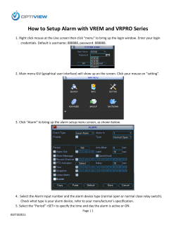
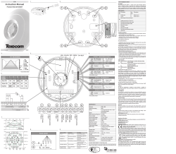
Macurco™ GD-2A Combustible Gas Detector
User Instructions
Important: These User Instructions are to be provided to the
homeowner/end user upon product installation. Each person installing or
using this equipment must read and understand the information in these
User Instructions before use. Installation of this equipment by untrained or
unqualified persons, or use that is not in accordance with these User
Instructions may adversely affect product performance and result in
sickness or death. For proper use see User Instructions or call Macurco
Technical Service.
GENERAL SAFETY INFORMATION
INTENDED USE
The GD-2A is a low voltage (12-24 VAC or VDC) electronic detector of
combustible, heating type gases. The GD-2A is designed for connection to
UL Listed Fire Alarm/Burglary Control Panels. NOTE: Any time the words
“Control Panel” or “Alarm Panel” or “Alarm Control Panel” are used in these
instructions, they refer to a UL Listed Fire Alarm/Burglary Control Panel.
Alarm control panels that work on 12 or 24 VDC can provide battery backup
to the GD-2A detectors. This combustible gas detector has been evaluated
by UL for methane (natural gas) and propane (LP) gas. It is NOT designed
to detect smoke, fire or carbon monoxide.
detectable and cause sickness or death. For proper use, see supervisor
or User Instructions, or call Macurco Technical Service.
• GD-2A may not function effectively below 32 °F or above 120°F. Using
the detector outside of this temperature range may adversely affect product
performance and result in sickness or death.
• This detector helps monitor for the presence and concentration level of
certain specified airborne gases. Misuse may produce an inaccurate
reading, which means that higher levels of the gas being monitored may be
present and could result in overexposure and cause sickness or death.
For proper use, see supervisor or User Instructions, or call Macurco
Technical Service.
• The GD-2A is not designed to measure compliance with Occupational
Safety and Health Administration (OSHA) commercial or industrial
standards.
• When the unit is powered up it performs a self-test during which the green
LED light will blink for a period of one and one half to two minutes.
Afterward, the green LED light will turn on continuously to indicate the unit is
in normal operation (ARMED). If the self-test fails or the green LED light
does not turn on continuously do not use. Failure to do so may adversely
affect product performance and result in sickness or death.
• Immediately exit the environment if there is an alarm condition on the
detector. Failure to do so may result in sickness or death.
• This detector will only indicate the presence of combustible gas at the
sensor. Combustible gas may be present in other areas. Accommodation
spaces should be well ventilated when household cleaning supplies or
similar contaminants are used.
• Do not cover or obstruct visual alarm LED. Doing so may adversely affect
product performance and result in sickness or death.
• Do not disassemble unit or attempt to repair or modify any component of
this detector. This detector contains no user serviceable parts, and
substitution of components may adversely affect product performance and
result in sickness or death.
CAUTION
• Avoid the use of harsh cleaning materials, abrasives and other organic
solvents. Such materials may permanently scratch the surfaces; damage
the sensor, labels, or instrument housing.
• If you have any doubts about the applicability of the equipment to your job
situation, consult an industrial hygienist or call Macurco Technical Service.
USE INSTRUCTIONS AND LIMITATIONS
LIST OF WARNINGS AND CAUTIONS
! WARNING
• Each person using this equipment must read and understand the
information in these User Instructions before use. Use of this equipment by
untrained or unqualified persons, or use that is not in accordance with these
User Instructions, may adversely affect product performance and result in
sickness or death.
• Use only for monitoring the gas which the sensor and detector are
designed to monitor. Failure to do so may result in exposures to gases not
! WARNING
Each person using this equipment must read and understand the information in
these User Instructions before use. Use of this equipment by untrained or
unqualified persons, or use that is not in accordance with these User Instructions,
may adversely affect product performance and result in sickness or death.
USE FOR
The GD-2A is an electronic detector of combustible, heating type gases
(natural gas and propane), designed for connection to alarm control panels.
It can operate on 12 to 24 VDC power from standby or interruptible panel
power, or be powered separately. The GD-2A is intended for installation in
buildings in non-hazardous locations such as residences, retail stores, office
buildings, and institutional buildings.
! WARNING
Use only for monitoring the gas which the sensor and detector are designed to
monitor. Failure to do so may result in exposures to gases not detectable and cause
sickness or death. For proper use, see supervisor or User Instructions, or call
Macurco Technical Service.
DO NOT USE FOR
The GD-2A is NOT intended for use in industrial applications such as
refineries, chemical plants, etc. The GD-2A does NOT detect carbon
monoxide. Do NOT mount the GD-2A in a corner. The GD-2A is designed
for connection to UL Listed Fire Alarm/Burglary Control Panels. Do not
connect the GD-2A to Fire Alarm Circuits, or Burglar Alarm or other signals.
The Alarm Control Panel must be dedicated to gas detection or have alarm
devices that provide a distinctive alarm for gas detection. Do NOT mount
the GD-2A in kitchens or bathrooms - alcohol’s, ammonia, cleaning solvents,
paint thinner, gasoline vapors, and aerosol propellants (aerosol cans such
as hair spray usually contain a combustible gas) may cause nuisance
alarms.
! WARNING
GD-2A may not function effectively below 32 °F or above 120°F. Using the detector
outside of this temperature range may adversely affect product performance and
result in sickness or death.
GENERAL DESCRIPTION
The GD-2A is a low voltage (12-24 VAC or VDC) electronic detector of
combustible, heating type gases, that has been evaluated by UL for
methane (natural gas) and propane (LP) gas. The GD-2A is designed for
connection to UL Listed Fire Alarm/Burglary Control Panels. The GD-2A has
a SPDT Alarm relay, for connection to control panels or other devices. The
GD-2A does NOT detect carbon monoxide. The GD-2A does not have an
internal audible sounder.
FEATURES
• LISTED TO UL STANDARD 2075 FOR THE STANDARD FOR SAFETY FOR
GAS AND VAPOR DETECTOR AND SENSORS
• SENSITIVITY TESTED BASED ON UL 1484 STANDARD FOR RESIDENTIAL
GAS DETECTORS
• DETECTS HEATING GASES: PROPANE (LP), NATURAL GAS (METHANE),
• SPDT ALARM AND N.C. TROUBLE RELAYS
• CAN BE SELF-RESTORING OR LATCHING
• ELECTRONIC SENSORS: NO MAINTENANCE OR RECALIBRATION
• TEMPERATURE COMPENSATED
• SIMPLE INSTALLATION AND OPERATION
• SUPERVISED SENSOR
SPECIFICATIONS
• SIZE: 4 ½ X 5 X 1 5/8 inches
• SHIPPING WEIGHT: 0.54 pound
• VOLTAGE: 12 to 24 VAC or VDC
• CURRENT (non-alarm): 45 mA @ 12 VDC, 22 mA @ 24 VDC, 65 mA @ 12 VAC,
45 mA @ 24 VAC
• CURRENT (in alarm): 70 mA @ 12 VDC, 35 mA @ 24 VDC, 100 mA @ 12 VAC,
65 mA @ 24 VAC
• COLOR: White
• SENSOR MAINTENANCE: Not required
• ALARM RELAY RATING: 0.125 AMPS, 40V, 3VA
• TROUBLE RELAY: 0.250 AMPS, 40V, 10VA
• OPERATING TEMPERATURE RANGE: 32° to 120° F
• ALARM SET POINT: Per UL 1484 (25% LEL)
INSTALLATION AND OPERATING INSTRUCTIONS
The following instructions are intended to serve as a guideline for the use of
the Macurco GD-2A Combustible Gas Detector. It is not to be considered
all-inclusive, nor is it intended to replace the policy and procedures for each
facility.
! WARNING
This detector helps monitor for the presence and concentration level of certain
specified airborne gases. Misuse may produce an inaccurate reading, which means
that higher levels of the gas being monitored may be present and could result in
overexposure and cause sickness or death. For proper use, see supervisor or
User Instructions, or call Macurco Technical Service.
LOCATION
A GD-2A is usually located in each room (except kitchens or bathrooms)
where there are gas appliances or through which gas pipes pass. Do NOT
mount the GD-2A in a corner. Do NOT mount the GD-2A in kitchens or
bathrooms - alcohol’s, ammonia, cleaning solvents, paint thinner, gasoline
vapors, and aerosol propellants (aerosol cans such as hair spray usually
contain a combustible gas) may cause alarms. Do NOT mount the GD-2A
where the normal ambient
This product is intended for use in ordinary indoor locations of family living
units and office workspaces.
! WARNING
The GD-2A is not designed to measure compliance with Occupational Safety and
Health Administration (OSHA) commercial or industrial standards.
INSTALLATION
1. If the gas used is natural gas (methane) mount the GD-2A on a wall about
one foot down from the ceiling. If the gas used is propane (LP), mount the
GD-2A on a wall or column one foot above the floor. Use the same spacing
as for smoke detectors- 30-foot centers, 900 square feet per detector.
The three part plastic case allows the GD-2A to be either surface mounted
or installed over a four-inch square or double gang electrical box, providing
a near flush mount. The GD-2A snap on front cover will need to be removed
before installation. To remove it, lightly pry the front cover off of the
mounting plate (middle section) with a coin or flat screwdriver inserted into
1. the vent at the bottom. The cover will snap off exposing the electronics
and mounting plate.
2. For flush mount, remove the 2 screws and rear cover from the mounting
plate and use the appropriate hole-pattern for installation. The four holes
toward the center of the mounting plate match the hole- pattern of a double
gang electrical box. The four holes near the corners match the pattern of a
four-inch square box. Mount the GD-2A so the “TOP” marked side of the
mounting plate is at the highest side. Snap the front cover back on when
finished, making sure that the lights line up with the access holes.
3. When using the GD-2A with normally closed initiating circuits, use the
Com. and N.C. alarm relay connections.
4. See wiring diagram and information below for connections of the GD-2A.
• UL 2075 Requirements - 12.4.1 Power supply leads provided for field
connection shall not be less than 6 inches (152 mm) long, provided with
strain relief, and shall be no smaller than 18 AWG (0.82 mm2). The
insulation, when thermoplastic, shall not be less than 1/32 inch (0.8 mm)
thick.
• Exception No. 1: A lead is not prohibited from being less than 6 inches
long when it is evident that the use of a longer lead results in damage to the
insulation.
• Exception No. 2: Solid copper leads as small as 26 AWG (0.13
not prohibited from use when:
mm2)
are
A. The current does not exceed 1 ampere for lengths up to 2 feet (61 cm)
and the current does not exceed 0.4 ampere for lengths from 2 feet up to 10
feet (3.05 m);
B. There are two or more conductors and they are covered by a common
jacket, or the equivalent; and
C. The assembled conductors comply with the requirements of the Strain
Relief Tests, Section 18.
• 12.4.2 Leads provided for field connection to power limited signaling
circuits, such as those employed for connection to remote signaling devices,
shall not be smaller than 16 AWG (1.3 mm2), for a single conductor; 19
AWG (0.65 mm2) for two or more conductors; and 26 AWG (0.13 mm2) for
four or more conductors of a multi-conductor cable. The conductor shall be
solid, bunch tinned stranded, or stranded copper. Stranded copper wire
consisting of not more than seven strands shall be employed only for 18
AWG (0.82 mm2) and larger conductors.
TYPICAL CONNECTION OF TWO GD-2A TO AN ALARM CONTROL PANEL
TYPICAL COVERAGE - 900 SQUARE FEET
5. The GD-2A uses a full wave bridge rectifier at its power input, so that it is
independent of the polarity of the input power. It can operate on DC or AC
voltages between 12 and 24 volts.
ALARMS
6. A switching regulator is used to efficiently match the wide input voltage
range to the fixed, internal power system. As a result the power
consumption is fairly constant at about 0.75 watts in normal operation, and
1.0 watt in alarm.
Immediately exit any environment if there is an alarm condition on the detector.
Failure to do so may result in sickness or death.
7. The alarm control panel zone inputs must be terminated with end of line
resistors (E.O.L.R.), which are provided with the panel. The GD-2A does not
have an internal audible sounder and must be connected to a UL Listed Fire
Alarm/Burglary Control Panel with a UL Listed audible device that provides
at least 85 DB sound output.
TESTING
! WARNING
The final alarm is determined by the configuration of the control panel, with
the GD-2A only switching its relay to actuate the panel. Do not connect the
GD-2A to Fire Alarm Circuits, or Burglar Alarm or other signals. The
illumination of the red (ALARM) light on the GD-2A indicates the alarm
condition. When an alarm occurs immediately evacuate the premises and
seek assistance.
POWER UP
! WARNING
! WARNING
When the unit is powered up it performs a self-test during which the green LED light
blinks for a period of one and one half to two minutes. Afterwards, the green LED
light will turn on continuously to indicate the unit is in normal operation (ARMED). If
the self-test fails or the green LED light does not turn on continuously do not use.
Failure to do so may adversely affect product performance and result in sickness
or death.
When power is first applied to the detector, it will go through a warm-up
period of one and one half to two minutes, during which alarms are inhibited.
The green LED light will turn on and off during the delay period. The green
light will turn on continuously (ARMED) afterwards to indicate the unit is in
normal operation.
OPERATION
1. Once the GD-2A is operational (ARMED) the green light will be on
continuously. If gas is detected the red LED (ALARM) turns on and the
SPDT alarm relay activates to indicate the alarm condition.
2. In the configuration, as shipped from the factory, the GD-2A is selfrestoring. When the air clears of gas, the red light turns off and the relay
switches to its normal state. A jumper wire on the circuit board can be
clipped to allow the unit to latch in upon alarm. Once latched in, power will
need to be interrupted to un-latch the alarm condition.
• The GD-2A can be modified, either before or after installation, to have a
latching output. Pull off the cover and locate the jumper wire labeled “CLIP
FOR LATCH IN” on the printed circuit board in the upper right hand side.
Clip or cut this jumper wire and separate the wire ends. Now the unit will
stay in alarm (once gas has exceeded the pre-set threshold) until the power
is interrupted. When replacing the cover, make sure the lights line up with
their access holes.
3. The GD-2A has a supervisory circuit of critical functions. A trouble
condition, due to failure of a non-reliable component, results in both lights
switching on and off and the normally closed trouble relay opening. A power
failure also causes the trouble relay to open.
This detector will only indicate the presence of combustible gas at the sensor.
Combustible gas may be present in other areas. Accommodation spaces should be
well ventilated when household cleaning supplies or similar contaminants are used.
In addition to the methane (natural gas) and propane (LP) gas that it is
designed to detect, the GD-2A can also be affected by a broad range of
combustible gases. Some of these that may cause an alarm are: alcohol,
ammonia, cleaning solvents, paint thinner, gasoline vapors, and aerosol
propellants. Aerosol cans such as hair spray usually contain a combustible
gas. Always make sure that there is adequate ventilation when you use
these products. Proper location, not in kitchens or bathrooms, will minimize
alarms due to normal use of household products.
TROUBLE INDICATOR
The trouble signal is determined mostly by the configuration of the alarm
panel, with the GD-2A trouble relay only providing an open circuit for
actuation. A failure of the gas-sensing element will result in both lights
turning on and off and the trouble relay opening. Failure of power supplies in
the GD-2A or a lack of power to the detector will result in the trouble relay
opening. The most common expected trouble would be a break in the wiring
between the panel and the GD-2A. When a trouble signal occurs call the
alarm panel installer for assistance.
! WARNING
Do not cover or obstruct visual alarm LED. Doing so may adversely affect product
performance and result in sickness or death.
MAINTENANCE
The GD-2A does not require regular maintenance. The unit uses a selfpurging semi-conductor sensor that has a long life expectancy. All service
and repair of the GD-2A are to be performed by Macurco. Macurco does not
sanction any third-party repair facilities.
! WARNING
Do not disassemble unit or attempt to repair or modify any component of this
instrument. This instrument contains no user serviceable parts, and substitution of
components may impair intrinsic safety which may adversely affect product
performance and result in sickness or death.
Once the unit is fully operational (the green light is on steady), test the unit
by directing gas from an unlighted butane cigarette lighter into the detector
near the left hand side through one of the vent holes. It will be necessary to
hold the lighter valve open for several seconds. The red light (ALARM) will
turn on, the alarm relay switches, and any devices connected should
activate. The detector should be tested regularly by using gas from an unlit
cigarette lighter, as detailed above.
CLEANING
The GD-2A should be cleaned using the soft brush attachment of your
vacuum cleaner. The GD-2A should be tested after cleaning to ensure the
unit is operating normally.
SENSOR POISONS
The gas-sensing tip in the detector is designed with extreme sensitivity to
the environment. As a result, the sensing function of the tip may deteriorate
if it is exposed to a direct spray from aerosols such as paints, silicone
vapors, etc., or to a high density of corrosive gases (such as hydrogen
sulfide, sulfur dioxide) for an extended period of time.
LIMITED WARRANTY
The Macurco GD-2A Combustible Gas Detector is warranted to be free from
defective material and workmanship for a period of two (2) years from the
date of manufacture (stamped on the unit). If any component becomes
defective during the warranty period, it will be replaced or repaired free of
charge, if the unit is returned in accordance with the instructions below. This
warranty does not apply to units that have been altered or had repair
attempted, or that have been subjected to abuse, accidental or otherwise.
The above warranty is in lieu of all other express warranties, obligations or
liabilities. THE IMPLIED WARRANTIES OF MERCHANTABILITY AND
FITNESS FOR PARTICULAR PURPOSE ARE LIMITED TO A PERIOD OF
TWO (2) YEARS Macurco shall not be liable for any incidental or
consequential damages for breach of this or any other warranty express or
implied arising out of or related to the use of said equipment. Manufacturer
or its agent’s liability shall be limited to replacement or repair as set forth
above. Buyer’s sole and exclusive remedies are return of the goods and
repayment of the price, or repair and replacement of non-conforming goods
or parts.
Manufactured by Aerionics, Inc.
Sioux Falls, SD
Email: [email protected]
Phone: 1-877-367-7891
Rev 03.10.2014
© Aerionics 2014. All rights reserved.
Macurco is a trademark of Aerionics, Inc.


© Copyright 2026