
HP3 Manipulator Manual Motoman NX100 Controller Part Number:
Motoman NX100 Controller
HP3
Manipulator Manual
Part Number:
Revision:
149209-1CD
0
Motoman, Incorporated
805 Liberty Lane
West Carrollton, OH 45449
TEL: (937) 847-6200
FAX: (937) 847-6277
24-Hour Service Hotline: (937) 847-3200
COMPLETE OUR ONLINE SURVEY
Motoman is committed to total customer satisfaction! Please give us your feedback on the technical manuals you
received with your Motoman robotic solution.
To participate, go to the following website:
http://www.motoman.com/forms/techpubs.asp
The information contained within this document is the proprietary property of Motoman, Inc., and may not be
copied, reproduced or transmitted to other parties without the expressed written authorization of Motoman,
Inc.
©2007 by MOTOMAN
All Rights Reserved
Because we are constantly improving our products, we reserve the right to change specifications without
notice. MOTOMAN is a registered trademark of YASKAWA Electric Manufacturing.
*2
%JCRVGT
+PVTQFWEVKQP
The Motoman HP3 and NX controller represent state-of-the-art technology in robotics today.
The Motoman HP3 is a high speed robot with a 3 kg payload. The robot has six individual
axes: Sweep, Lower arm, Upper arm, Rotate, Bend, and Twist. The NX controller coodinates
the operation of the robot with external equipment such as power supply and positioning
tables. The NX controller processes input and output signals, maintains variable data, and
performs numeric processing to convert to and from different coordinate systems.
Furthermore, it provides main logic functions, servo control, program and constant data
memory, and power distribution. Please read this manual thoroughly to familiarize yourself
with the many aspects of the robot and NX controller.
#DQWV6JKU&QEWOGPV
This manual provides system information for the HP3 robot and NX controller and contains
the following sections:
5'%6+10+0641&7%6+10
Provides general information about the structure of this manual, a list of reference documents,
and customer service information.
5'%6+105#('6;
This section provides information regarding the safe use and operation of Motoman products.
5'%6+10*2+05647%6+105
Provides detailed information about the HP3 robot, including installation, wiring,
specifications, and maintenance.
(KPCN
RCIG
/CPKRWNCVQT/CPWCN
%JCRVGT
+PVTQFWEVKQP
4GHGTGPEGVQ1VJGT&QEWOGPVCVKQP
For additional information refer to the following:
•
NX100 Controller Manual (P/N 149201-1)
•
Concurrent I/O Manual (P/N 149230-1)
•
Operator’s Manual for your application
•
Vendor manuals for system components not manufactured by Motoman
%WUVQOGT5GTXKEG+PHQTOCVKQP
If you are in need of technical assistance, contact the Motoman service staff at (937) 847-3200.
Please have the following information ready before you call:
RCIG
•
Robot Type (HP3)
•
Application Type (arcwelding, spot welding, handling)
•
Robot Serial Number (located on back side of robot arm)
•
Robot Sales Order Number (located on back of controller)
(KPCN
*2
%JCRVGT
5CHGV[
+PVTQFWEVKQP
+VKUVJGRWTEJCUGT UTGURQPUKDKNKV[VQGPUWTGVJCVCNNNQECNEQWPV[UVCVG
CPFPCVKQPCNEQFGUTGIWNCVKQPUTWNGUQTNCYUTGNCVKPIVQUCHGV[CPFUCHG
QRGTCVKPIEQPFKVKQPUHQTGCEJKPUVCNNCVKQPCTGOGVCPFHQNNQYGF
:HVXJJHVWWKDW\RXREWDLQDQGUHYLHZDFRS\RIWKH$16,5,$1DWLRQDO6DIHW\6WDQGDUGIRU
,QGXVWULDO5RERWVDQG5RERW6\VWHPV7KLVLQIRUPDWLRQFDQEHREWDLQHGIURPWKH5RERWLF,QGXVWULHV
$VVRFLDWLRQE\UHTXHVWLQJ$16,5,$57KHDGGUHVVLVDVIROORZV
5RERWLF,QGXVWULHV$VVRFLDWLRQ
9LFWRUV:D\
32%R[
$QQ$UERU0LFKLJDQ
7(/
)$;
,17(51(7ZZZURERWLFVRQOLQHFRP
8OWLPDWHO\WKHEHVWVDIHJXDUGLVWUDLQHGSHUVRQQHO7KHXVHULVUHVSRQVLEOHIRUSURYLGLQJSHUVRQQHO
ZKRDUHDGHTXDWHO\WUDLQHGWRRSHUDWHSURJUDPDQGPDLQWDLQWKHURERWFHOO7KHURERWPXVWQRWEH
RSHUDWHGE\SHUVRQQHOZKRKDYHQRWEHHQWUDLQHG
:HUHFRPPHQGWKDWDOOSHUVRQQHOZKRLQWHQGWRRSHUDWHSURJUDPUHSDLURUXVHWKHURERWV\VWHPEH
WUDLQHGLQDQDSSURYHG0RWRPDQWUDLQLQJFRXUVHDQGEHFRPHIDPLOLDUZLWKWKHSURSHURSHUDWLRQRIWKH
V\VWHP
(KPCN
RCIG
/CPKRWNCVQT/CPWCN
%JCRVGT
5CHGV[
7KLVVDIHW\VHFWLRQDGGUHVVHVWKHIROORZLQJ
6WDQGDUG&RQYHQWLRQV6HFWLRQ
*HQHUDO6DIHJXDUGLQJ7LSV6HFWLRQ
0HFKDQLFDO6DIHW\'HYLFHV6HFWLRQ
,QVWDOODWLRQ6DIHW\6HFWLRQ
3URJUDPPLQJ2SHUDWLRQDQG0DLQWHQDQFH6DIHW\6HFWLRQ
5VCPFCTF%QPXGPVKQPU
7KLVPDQXDOLQFOXGHVWKHIROORZLQJDOHUWV–LQGHVFHQGLQJRUGHURIVHYHULW\–WKDWDUHHVVHQWLDOWRWKH
VDIHW\RISHUVRQQHODQGHTXLSPHQW$V\RXUHDGWKLVPDQXDOSD\FORVHDWWHQWLRQWRWKHVHDOHUWVWR
LQVXUHVDIHW\ZKHQLQVWDOOLQJRSHUDWLQJSURJUDPPLQJDQGPDLQWDLQLQJWKLVHTXLSPHQW
%"/(&3
+PHQTOCVKQPCRRGCTKPIKPC�)'4EQPEGTPUVJGRTQVGEVKQPQHRGTUQPPGNHTQOVJGKOOGFKCVG
CPFKOOKPGPVJC\CTFUVJCVKHPQVCXQKFGFYKNNTGUWNVKPKOOGFKCVGUGTKQWURGTUQPCNKPLWT[QT
NQUUQHNKHGKPCFFKVKQPVQGSWKROGPVFCOCIG
8"3/*/(
+PHQTOCVKQPCRRGCTKPIKPC9#40+0)EQPEGTPUVJGRTQVGEVKQPQHRGTUQPPGNCPFGSWKROGPVHTQO
RQVGPVKCNJC\CTFUVJCVECPTGUWNVKPRGTUQPCNKPLWT[QTNQUUQHNKHGKPCFFKVKQPVQGSWKROGPV
FCOCIG
$"65*0/
+PHQTOCVKQPCRRGCTKPIKPC%#76+10EQPEGTPUVJGRTQVGEVKQPQHRGTUQPPGNCPFGSWKROGPV
UQHVYCTGCPFFCVCHTQOJC\CTFUVJCVECPTGUWNVKPOKPQTRGTUQPCNKPLWT[QTGSWKROGPVFCOCIG
1RWH,QIRUPDWLRQDSSHDULQJLQD1RWHSURYLGHVDGGLWLRQDOLQIRUPDWLRQZKLFKLVKHOSIXOLQXQGHUVWDQGLQJWKHLWHPEHLQJ
H[SODLQHG
RCIG
(KPCN
*2
)GPGTCN5CHGIWCTFKPI6KRU
$OORSHUDWRUVSURJUDPPHUVSODQWDQGWRROLQJHQJLQHHUVPDLQWHQDQFHSHUVRQQHOVXSHUYLVRUVDQG
DQ\RQHZRUNLQJQHDUWKHURERWPXVWEHFRPHIDPLOLDUZLWKWKHRSHUDWLRQRIWKLVHTXLSPHQW$OO
SHUVRQQHOLQYROYHGZLWKWKHRSHUDWLRQRIWKHHTXLSPHQWPXVWXQGHUVWDQGSRWHQWLDOGDQJHUVRI
RSHUDWLRQ*HQHUDOVDIHJXDUGLQJWLSVDUHDVIROORZV
,PSURSHURSHUDWLRQFDQUHVXOWLQSHUVRQDOLQMXU\DQGRUGDPDJHWRWKHHTXLSPHQW2QO\
WUDLQHGSHUVRQQHOIDPLOLDUZLWKWKHRSHUDWLRQRIWKLVURERWWKHRSHUDWRU
VPDQXDOVWKHV\VWHP
HTXLSPHQWDQGRSWLRQVDQGDFFHVVRULHVVKRXOGEHSHUPLWWHGWRRSHUDWHWKLVURERWV\VWHP
'RQRWHQWHUWKHURERWFHOOZKLOHLWLVLQDXWRPDWLFRSHUDWLRQ3URJUDPPHUVPXVWKDYHWKH
WHDFKSHQGDQWZKHQWKH\HQWHUWKHURERWFHOO
,PSURSHUFRQQHFWLRQVFDQGDPDJHWKHURERW$OOFRQQHFWLRQVPXVWEHPDGHZLWKLQWKH
VWDQGDUGYROWDJHDQGFXUUHQWUDWLQJVRIWKHURERW,2,QSXWVDQG2XWSXWV
7KHURERWPXVWEHSODFHGLQ(PHUJHQF\6WRS(6723PRGHZKHQHYHULWLVQRWLQXVH
,QDFFRUGDQFHZLWK$16,5,$5VHFWLRQ6RXUFHVRI(QHUJ\XVH
ORFNRXWWDJRXWSURFHGXUHVGXULQJHTXLSPHQWPDLQWHQDQFH5HIHUDOVRWR6HFWLRQ
&)53DUW2FFXSDWLRQDO6DIHW\DQG+HDOWK6WDQGDUGVIRU*HQHUDO,QGXVWU\
26+$
/GEJCPKECN5CHGV[&GXKEGU
7KHVDIHRSHUDWLRQRIWKHURERWSRVLWLRQHUDX[LOLDU\HTXLSPHQWDQGV\VWHPLVXOWLPDWHO\WKHXVHU
V
UHVSRQVLELOLW\7KHFRQGLWLRQVXQGHUZKLFKWKHHTXLSPHQWZLOOEHRSHUDWHGVDIHO\VKRXOGEHUHYLHZHG
E\WKHXVHU7KHXVHUPXVWEHDZDUHRIWKHYDULRXVQDWLRQDOFRGHV$16,5,$5VDIHW\
VWDQGDUGVDQGRWKHUORFDOFRGHVWKDWPD\SHUWDLQWRWKHLQVWDOODWLRQDQGXVHRILQGXVWULDOHTXLSPHQW
$GGLWLRQDOVDIHW\PHDVXUHVIRUSHUVRQQHODQGHTXLSPHQWPD\EHUHTXLUHGGHSHQGLQJRQV\VWHP
LQVWDOODWLRQRSHUDWLRQDQGRUORFDWLRQ7KHIROORZLQJVDIHW\HTXLSPHQWLVSURYLGHGDVVWDQGDUG
6DIHW\IHQFHVDQGEDUULHUV
/LJKWFXUWDLQVDQGRUVDIHW\PDWV
'RRULQWHUORFNV
(PHUJHQF\VWRSSDOPEXWWRQVORFDWHGRQRSHUDWRUVWDWLRQURERWFRQWUROOHUDQG
SURJUDPPLQJSHQGDQW
&KHFNDOOVDIHW\HTXLSPHQWIUHTXHQWO\IRUSURSHURSHUDWLRQ5HSDLURUUHSODFHDQ\QRQIXQFWLRQLQJ
VDIHW\HTXLSPHQWLPPHGLDWHO\
(KPCN
RCIG
/CPKRWNCVQT/CPWCN
%JCRVGT
5CHGV[
+PUVCNNCVKQP5CHGV[
6DIHLQVWDOODWLRQLVHVVHQWLDOIRUSURWHFWLRQRISHRSOHDQGHTXLSPHQW7KHIROORZLQJVXJJHVWLRQVDUH
LQWHQGHGWRVXSSOHPHQWEXWQRWUHSODFHH[LVWLQJIHGHUDOORFDODQGVWDWHODZVDQGUHJXODWLRQV
$GGLWLRQDOVDIHW\PHDVXUHVIRUSHUVRQQHODQGHTXLSPHQWPD\EHUHTXLUHGGHSHQGLQJRQV\VWHP
LQVWDOODWLRQRSHUDWLRQDQGRUORFDWLRQ,QVWDOODWLRQWLSVDUHDVIROORZV
%HVXUHWKDWRQO\TXDOLILHGSHUVRQQHOIDPLOLDUZLWKQDWLRQDOFRGHVORFDOFRGHVDQG
$16,5,$5VDIHW\VWDQGDUGVDUHSHUPLWWHGWRLQVWDOOWKHHTXLSPHQW
,GHQWLI\WKHZRUNHQYHORSHRIHDFKURERWZLWKIORRUPDUNLQJVVLJQVDQGEDUULHUV
3RVLWLRQDOOFRQWUROOHUVRXWVLGHWKHURERWZRUNHQYHORSH
:KHQHYHUSRVVLEOHLQVWDOOVDIHW\IHQFHVWRSURWHFWDJDLQVWXQDXWKRUL]HGHQWU\LQWRWKHZRUN
HQYHORSH
(OLPLQDWHDUHDVZKHUHSHUVRQQHOPLJKWJHWWUDSSHGEHWZHHQDPRYLQJURERWDQGRWKHU
HTXLSPHQWSLQFKSRLQWV
3URYLGHVXIILFLHQWURRPLQVLGHWKHZRUNFHOOWRSHUPLWVDIHWHDFKLQJDQGPDLQWHQDQFH
SURFHGXUHV
2TQITCOOKPI1RGTCVKQPCPF/CKPVGPCPEG5CHGV[
$OORSHUDWRUVSURJUDPPHUVSODQWDQGWRROLQJHQJLQHHUVPDLQWHQDQFHSHUVRQQHOVXSHUYLVRUVDQG
DQ\RQHZRUNLQJQHDUWKHURERWPXVWEHFRPHIDPLOLDUZLWKWKHRSHUDWLRQRIWKLVHTXLSPHQW,PSURSHU
RSHUDWLRQFDQUHVXOWLQSHUVRQDOLQMXU\DQGRUGDPDJHWRWKHHTXLSPHQW2QO\WUDLQHGSHUVRQQHO
IDPLOLDUZLWKWKHRSHUDWLRQPDQXDOVHOHFWULFDOGHVLJQDQGHTXLSPHQWLQWHUFRQQHFWLRQVRIWKLVURERW
VKRXOGEHSHUPLWWHGWRSURJUDPRSHUDWHDQGPDLQWDLQWKHV\VWHP$OOSHUVRQQHOLQYROYHGZLWKWKH
RSHUDWLRQRIWKHHTXLSPHQWPXVWXQGHUVWDQGSRWHQWLDOGDQJHUVRIRSHUDWLRQ
RCIG
,QVSHFWWKHURERWDQGZRUNHQYHORSHWREHVXUHQRSRWHQWLDOO\KD]DUGRXVFRQGLWLRQVH[LVW%H
VXUHWKHDUHDLVFOHDQDQGIUHHRIZDWHURLOGHEULVHWF
%HVXUHWKDWDOOVDIHJXDUGVDUHLQSODFH&KHFNDOOVDIHW\HTXLSPHQWIRUSURSHURSHUDWLRQ
5HSDLURUUHSODFHDQ\QRQIXQFWLRQLQJVDIHW\HTXLSPHQWLPPHGLDWHO\
'RQRWHQWHUWKHURERWFHOOZKLOHLWLVLQDXWRPDWLFRSHUDWLRQ%HVXUHWKDWRQO\WKHSHUVRQ
KROGLQJWKHSURJUDPPLQJSHQGDQWHQWHUVWKHZRUNFHOO
&KHFNWKH(6723EXWWRQRQWKHSURJUDPPLQJSHQGDQWIRUSURSHURSHUDWLRQEHIRUH
SURJUDPPLQJ7KHURERWPXVWEHSODFHGLQ(PHUJHQF\6WRS(6723PRGHZKHQHYHULWLV
QRWLQXVH
%DFNXSDOOSURJUDPVDQGMREVRQWRVXLWDEOHPHGLDEHIRUHSURJUDPFKDQJHVDUHPDGH7R
DYRLGORVVRILQIRUPDWLRQSURJUDPVRUMREVDEDFNXSPXVWDOZD\VEHPDGHEHIRUHDQ\
VHUYLFHSURFHGXUHVDUHGRQHDQGEHIRUHDQ\FKDQJHVDUHPDGHWRRSWLRQVDFFHVVRULHVRU
HTXLSPHQW
(KPCN
*2
$Q\PRGLILFDWLRQVWR3$576\VWHP6HFWLRQRIWKHURERWFRQWUROOHUFRQFXUUHQW,2
SURJUDPFDQFDXVHVHYHUHSHUVRQDOLQMXU\RUGHDWKDVZHOODVGDPDJHWRWKHURERW'RQRW
PDNHDQ\PRGLILFDWLRQVWR3$576\VWHP6HFWLRQ0DNLQJDQ\FKDQJHVZLWKRXWWKHZULWWHQ
SHUPLVVLRQRI0RWRPDQZLOO92,'<285:$55$17<
6RPHRSHUDWLRQVUHTXLUHVWDQGDUGSDVVZRUGVDQGVRPHUHTXLUHVSHFLDOSDVVZRUGV6SHFLDO
SDVVZRUGVDUHIRU0RWRPDQXVHRQO\<285:$55$17<:,//%(92,'LI\RXXVH
WKHVHVSHFLDOSDVVZRUGV
7KHURERWFRQWUROOHUDOORZVPRGLILFDWLRQVRI3$578VHU6HFWLRQRIWKHFRQFXUUHQW,2
SURJUDPDQGPRGLILFDWLRQVWRFRQWUROOHUSDUDPHWHUVIRUPD[LPXPURERWSHUIRUPDQFH*UHDW
FDUHPXVWEHWDNHQZKHQPDNLQJWKHVHPRGLILFDWLRQV$OOPRGLILFDWLRQVPDGHWRWKH
FRQWUROOHUZLOOFKDQJHWKHZD\WKHURERWRSHUDWHVDQGFDQFDXVHVHYHUHSHUVRQDOLQMXU\RU
GHDWKDVZHOODVGDPDJHWKHURERWDQGRWKHUSDUWVRIWKHV\VWHP'RXEOHFKHFNDOO
PRGLILFDWLRQVXQGHUHYHU\PRGHRIURERWRSHUDWLRQWRHQVXUHWKDW\RXKDYHQRWFUHDWHG
KD]DUGVRUGDQJHURXVVLWXDWLRQV
&KHFNDQGWHVWDQ\QHZRUPRGLILHGSURJUDPDWORZVSHHGIRUDWOHDVWRQHIXOOF\FOH
7KLVHTXLSPHQWKDVPXOWLSOHVRXUFHVRIHOHFWULFDOVXSSO\(OHFWULFDOLQWHUFRQQHFWLRQVDUH
PDGHEHWZHHQWKHFRQWUROOHUDQGRWKHUHTXLSPHQW'LVFRQQHFWDQGORFNRXWWDJRXWDOO
HOHFWULFDOFLUFXLWVEHIRUHPDNLQJDQ\PRGLILFDWLRQVRUFRQQHFWLRQV
'RQRWSHUIRUPDQ\PDLQWHQDQFHSURFHGXUHVEHIRUHUHDGLQJDQGXQGHUVWDQGLQJWKHSURSHU
SURFHGXUHVLQWKHDSSURSULDWHPDQXDO
8VHSURSHUUHSODFHPHQWSDUWV
,PSURSHUFRQQHFWLRQVFDQGDPDJHWKHURERW$OOFRQQHFWLRQVPXVWEHPDGHZLWKLQWKH
VWDQGDUGYROWDJHDQGFXUUHQWUDWLQJVRIWKHURERW,2,QSXWVDQG2XWSXWV
(KPCN
RCIG
/CPKRWNCVQT/CPWCN
%JCRVGT
5CHGV[
016'5
RCIG
(KPCN
YASKAWA
MOTOMAN-HP3
INSTRUCTIONS
TYPE: YR-HP3-A00 (STANDARD SPECIFICATION)
Upon receipt of the product and prior to initial operation, read these instructions thoroughly, and retain
for future reference.
MOTOMAN INSTRUCTIONS
MOTOMAN-HP3 INSTRUCTIONS
NX100 INSTRUCTIONS
NX100 OPERATOR’S MANUAL
NX100 MAINTENANCE MANUAL
The NX100 operator’s manuals above correspond to specific usage.
Be sure to use the appropriate manual.
YASKAWA
MANUAL NO.
HW0482107
1
HW0482107
MANDATORY
• This instruction manual is intended to explain operating instructions
and maintenance procedures primarily for the MOTOMAN-HP3.
• General items related to safety are listed in the Section 1: Safety of the
NX100 instructions. To ensure correct and safe operation, carefully
read the NX100 instructions before reading this manual.
CAUTION
• Some drawings in this manual are shown with the protective covers or
shields removed for clarity. Be sure all covers and shields are replaced
before operating this product.
• The drawings and photos in this manual are representative examples
and differences may exist between them and the delivered product.
• YASKAWA may modify this model without notice when necessary due to
product improvements, modifications, or changes in specifications.
If such modification is made, the manual number will also be revised.
• If your copy of the manual is damaged or lost, contact a YASKAWA representative to order a new copy. The representatives are listed on the
back cover. Be sure to tell the representative the manual number listed
on the front cover.
• YASKAWA is not responsible for incidents arising from unauthorized
modification of its products. Unauthorized modification voids your product’s warranty.
ii
HW0482107
HW0482107
Notes for Safe Operation
Read this manual carefully before installation, operation, maintenance, or inspection of the
MOTOMAN-HP3 and the NX100.
In this manual, the Notes for Safe Operation are classified as “WARNING”, “CAUTION”,
“MANDATORY”, or “PROHIBITED”.
WARNING
Indicates a potentially hazardous situation which, if not avoided,
could result in death or serious injury to personnel.
CAUTION
Indicates a potentially hazardous situation which, if not avoided,
could result in minor or moderate injury to personnel and damage to equipment. It may also be used to alert against unsafe
practices.
MANDATORY
Always be sure to follow explicitly the items listed under this
heading.
PROHIBITED
Must never be performed.
Even items described as “CAUTION” may result in a serious accident in some situations.
At any rate, be sure to follow these important items.
NOTE To ensure safe and efficient operation at all times, be sure to follow all instructions, even if
not designated as “CAUTION” and “WARNING”.
iii
HW0482107
HW0482107
WARNING
• Before operating the manipulator, check that servo power is turned OFF
when the emergency stop buttons on the front door of the NX100 and
programing pendant are pressed.
When the servo power is turned OFF, the SERVO ON LED on the programing pendant is turned OFF.
Injury or damage to machinery may result if the emergency stop circuit cannot stop the
manipulator during an emergency. The manipulator should not be used if the emergency
stop buttons do not function.
Emergency Stop Button
• Once the emergency stop button is released, clear the cell of all items
which could interfere with the operation of the manipulator.
Then turn the servo power ON.
Injury may result from unintentional or unexpected manipulator motion.
TURN
Release of Emergency Stop
• Observe the following precautions when performing teaching operations
within the working envelope of the manipulator:
- View the manipulator from the front whenever possible.
- Always follow the predetermined operating procedure.
- Ensure that you have a safe place to retreat in case of emergency.
Improper or unintended manipulator operation may result in injury.
• Confirm that no persons are present in the manipulator’s work envelope
and that you are in a safe location before:
- Turning on the NX100 power.
- Moving the manipulator with the programing pendant.
- Running check operations.
- Performing automatic operations.
Injury may result if anyone enters the working envelope of the manipulator during operation. Always press an emergency stop button immediately if there is a problem.
The emergency stop button is located on the right of the front door of the NX100 and programing pendant.
iv
HW0482107
HW0482107
CAUTION
• Perform the following inspection procedures prior to conducting manipulator teaching. If problems are found, repair them immediately,
and be sure that all other necessary processing has been performed.
-Check for problems in manipulator movement.
-Check for damage to insulation and sheathing of external wires.
• Always return the programing pendant to the hook on the NX100 cabinet after use.
The programing pendant can be damaged if it is left in the manipulator’s work area, on the
floor, or near fixtures.
• Read and understand the Explanation of the Warning Labels in the
NX100 instructions before operating the manipulator.
Definition of Terms Used Often in This Manual
The MOTOMAN manipulator is the YASKAWA industrial robot product.
The manipulator usually consists of the controller, the programing pendant, and manipulator
cables.
In this manual, the equipment is designated as follows:
Equipment
Manual Designation
NX100 Controller
NX100
NX100 Programing Pendant
Programing Pendant
Cable between the manipulator and controller
Manipulator Cable
v
HW0482107
HW0482107
Explanation of Warning Labels
The following warning labels are attached to the manipulator.
Always follow the warnings on the labels.
Also, an identification label with important information is placed on the body of the manipulator. Prior to operating the manipulator, confirm the contents.
WARNING Label B
Nameplate
WARNING
Moving parts
may cause
injury
WARNING Label A
WARNING Label A:
Nameplate
WARNING
MOTOMAN
TYPE
PAYLOAD
ORDER NO.
kg
MASS
Moving parts
may cause
injury
kg
DATE
SERIAL NO.
YASKAWA ELECTRIC CORPORAION JAPAN
WARNING Label B:
WARNING
Do not enter
robot work area.
vi
HW0482107
HW0482107
1
Product Confirmation
1.1 Contents Confirmation . . . . . . . . . . . . . . . . . . . . . . . . . . . . . 1-1
1.2 Order Number Confirmation . . . . . . . . . . . . . . . . . . . . . . . 1-2
2
Transporting
2.1 Transporting Method
. . . . . . . . . . . . . . . . . . . . . . . . . . . . . . 2-1
2.1.1 Using a Crane . . . . . . . . . . . . . . . . . . . . . . . . . . . . . . . . . . . . . .2-1
2.1.2 Using a Forklift. . . . . . . . . . . . . . . . . . . . . . . . . . . . . . . . . . . . . .2-2
2.2 Shipping Bolts and Brackets . . . . . . . . . . . . . . . . . . . . . . . 2-3
3
Installation
3.1 Installation of the Safeguarding . . . . . . . . . . . . . . . . . . . . 3-2
3.2 Mounting Procedures for Manipulator Base . . . . . . . . 3-2
3.2.1 Mounting Example. . . . . . . . . . . . . . . . . . . . . . . . . . . . . . . . . . .3-3
3.3 Types of Mounting . . . . . . . . . . . . . . . . . . . . . . . . . . . . . . . . . 3-4
3.3.1 S-Axis Operating Range . . . . . . . . . . . . . . . . . . . . . . . . . . . . . .3-4
3.3.2 Fixing the Manipulator Base . . . . . . . . . . . . . . . . . . . . . . . . . . .3-4
3.3.3 Precautions to Prevent the Manipulator from Falling. . . . . . . . .3-4
3.4 Location . . . . . . . . . . . . . . . . . . . . . . . . . . . . . . . . . . . . . . . . . . . 3-5
4
Wiring
4.1 Grounding . . . . . . . . . . . . . . . . . . . . . . . . . . . . . . . . . . . . . . . . . 4-2
4.2 Cable Connection . . . . . . . . . . . . . . . . . . . . . . . . . . . . . . . . . 4-2
4.2.1 Connection to the Manipulator. . . . . . . . . . . . . . . . . . . . . . . . . .4-3
4.2.2 Connection to the NX100 . . . . . . . . . . . . . . . . . . . . . . . . . . . . .4-3
5
Basic Specifications
5.1
5.2
5.3
5.4
5.5
Basic Specifications . . . . . . . . . . . . . . . . . . . . . . . . . . . . . . .
Part Names and Working Axes . . . . . . . . . . . . . . . . . . . .
Baseplate Dimensions . . . . . . . . . . . . . . . . . . . . . . . . . . . . .
Dimensions and P-Point Maximum Envelope . . . . . .
Alterable Operating Range . . . . . . . . . . . . . . . . . . . . . . . .
vii
HW0482107
5-1
5-2
5-2
5-3
5-4
HW0482107
6
Allowable Load for Wrist Axis and Wrist Flange
6.1 Allowable Wrist Load . . . . . . . . . . . . . . . . . . . . . . . . . . . . . . . 6-1
6.2 Wrist Flange . . . . . . . . . . . . . . . . . . . . . . . . . . . . . . . . . . . . . . . 6-3
7
System Application
7.1 Peripheral Equipment Mounts . . . . . . . . . . . . . . . . . . . . . . 7-1
7.1.1 Allowable Load . . . . . . . . . . . . . . . . . . . . . . . . . . . . . . . . . . . . . 7-1
7.2 Internal User I/O Wiring Harness and Air Lines . . . . . 7-2
8
Electrical Equipment Specification
8.1 Internal Connections
9
. . . . . . . . . . . . . . . . . . . . . . . . . . . . . . . 8-1
Maintenance and Inspection
9.1 Inspection Schedule . . . . . . . . . . . . . . . . . . . . . . . . . . . . . . . . 9-1
9.2 Notes on Maintenance Procedures . . . . . . . . . . . . . . . . . 9-5
9.2.1 Battery pack Replacement . . . . . . . . . . . . . . . . . . . . . . . . . . . . 9-5
9.2.2 Grease Replenishment for S-Axis Speed Reducer . . . . . . . . . 9-7
Grease Replenishment (Refer to " Fig. 23 S-Axis
Speed Reducer Diagram ".) . . . . . . . . . . . . . . . . . . . . . . . . . 9-7
9.2.3 Grease Replenishment for L-Axis Speed Reducer . . . . . . . . . . 9-8
Grease Replenishment (Refer to " Fig. 24 L-Axis
Speed Reducer Diagram ".) . . . . . . . . . . . . . . . . . . . . . . . . . 9-8
9.2.4 Grease Replenishment for U-Axis Speed Reducer . . . . . . . . . 9-9
Grease Replenishment (Refer to " Fig. 25 U-Axis
Speed Reducer Diagram ".) . . . . . . . . . . . . . . . . . . . . . . . . . 9-9
9.2.5 Grease Replenishment for R-Axis Speed Reducer . . . . . . . . 9-10
Grease Replenishment (Refer to " Fig. 26 R-Axis
Speed Reducer Diagram ".) . . . . . . . . . . . . . . . . . . . . . . . . 9-10
9.2.6 Grease Replenishment for B- and T-Axes
Speed Reducers . . . . . . . . . . . . . . . . . . . . . . . . . . . . . . . . . . . 9-11
Grease Replenishment for B-axis (Refer to
" Fig. 27 B- and T-Axes Speed Reducers Diagram ".). . . . 9-11
Grease Replenishment for T-axis (Refer to
" Fig. 27 B- and T-Axes Speed Reducers Diagram ".). . . . 9-12
9.2.7 Notes for Maintenance . . . . . . . . . . . . . . . . . . . . . . . . . . . . . . 9-12
Wrist Unit . . . . . . . . . . . . . . . . . . . . . . . . . . . . . . . . . . . . . . 9-12
Battery Pack Connector (with CAUTION label) . . . . . . . . . 9-13
10
Recommended Spare Parts
viii
HW0482107
HW0482107
11
Parts List
11.1
11.2
11.3
11.4
S-axis Unit . . . . . . . . . . . . . . . . . . . . . . . . . . . . . . . . . . . . . .
L-axis Unit . . . . . . . . . . . . . . . . . . . . . . . . . . . . . . . . . . . . . .
U(R)-axis Unit . . . . . . . . . . . . . . . . . . . . . . . . . . . . . . . . . . .
Wrist Unit . . . . . . . . . . . . . . . . . . . . . . . . . . . . . . . . . . . . . . .
ix
HW0482107
11-1
11-3
11-5
11-7
HW0482107
1.1 Contents Confirmation
1 Product Confirmation
CAUTION
• Confirm that the manipulator and the NX100 have the same order number. Special care must be taken when more than one manipulator is to
be installed.
If the numbers do not match, manipulators may not perform as expected and cause injury
or damage.
1.1
Contents Confirmation
Confirm the contents of the delivery when the product arrives.
Standard delivery includes the following four items (Information for the content of optional
goods is given separately):
• Manipulator
• NX100
• Programing Pendant
• Manipulator Cable (2 cables)
1-1
HW0482107
HW0482107
1.2 Order Number Confirmation
1.2
Order Number Confirmation
Check that the order number of the manipulator corresponds to the NX100. The order number
is located on a label as shown below.
Label (Enlarged View)
THE MANIPULATOR AND THE CONTROLLER
SHOULD HAVE SAME ORDER NUMBER.
ORDER NO.
NX100
******
ERCR-
TYPE
Check that the manipulator
and the NX100 have the
same order number.
POWER SUPPLY
200V
220V
50Hz
50/60Hz
3PHASE
kVA
SERIAL No.
DATE
MADE IN JAPAN
NJ2484-1
THE MANIPULATOR AND THE CONTROLLER
SHOULD HAVE SAME ORDER NUMBER.
ORDER NO.
NJ1529
WARNING
Do not open the door
ET
RES
OFF
TR
IPP
ED
ON
(b) Manipulator (Top View)
(a) NX100 (Front View)
Fig. 1 Location of Order Number Labels
1-2
HW0482107
HW0482107
2.1 Transporting Method
2 Transporting
CAUTION
• Sling applications and crane or forklift operations must be performed by
authorized personnel only.
Failure to observe this caution may result in injury or damage.
• Avoid excessive vibration or shock during transportation.
Failure to observe this caution may adversely affect the performance as the system consists of precision components.
2.1
NOTE
Transporting Method
• Check that the eyebolts are securely fastened.
• The weight of the manipulator is approximately 47 kg including the shipping bolts and
brackets. Use a wire rope strong enough to withstand the weight.
• Attached eyebolts are designed to support the manipulator mass. Do not use them for
anything other than transporting the manipulator.
• Mount the shipping bolts and brackets for transporting the manipulator.
• Avoid putting external force on the arm or motor unit when transporting by a crane, forklift, or other equipment. Failure to observe this instruction may result in injury.
2.1.1
Using a Crane
As a rule, when removing the manipulator from the package and moving it, a crane should be
used. The manipulator should be lifted using wire rope.
Be sure the manipulator is fixed with the shipping bolts and brackets before transporting, and
lift it in the posture as shown in " Fig. 2 Transporting Position ".
2-1
HW0482107
HW0482107
2.1 Transporting Method
B
A
Fig. 2 Transporting Position
2.1.2
Using a Forklift
When using a forklift, the manipulator should be fixed on a pallet with shipping bolts and
brackets as shown in " Fig. 3 Using a Forklift ". Insert claws under the pallet and lift it. The
pallet must be strong enough to support the manipulator. Transporting of the manipulator must
be performed slowly in order to avoid overturning or slippage.
Bolt M10 (4 bolts)
Pallet
Forklift claw entry
Fig. 3 Using a Forklift
2-2
HW0482107
HW0482107
2.2 Shipping Bolts and Brackets
2.2
Shipping Bolts and Brackets
The manipulator is equipped with shipping bolts and brackets A and B in " Fig. 2 Transporting
Position ", to minimize external force during the transportation.
• The shipping bolts and brackets are painted yellow.
Before turning ON the power, make sure that the shipping bolts and brackets are
removed. The shipping bolts and brackets then must be stored for future use, in the event
that the manipulator must be moved again.
NOTE
Position
Bolt Type
Pcs
A
Hexagon socket head cap screw M6
(length: 15 mm) (tensile strength: 1200 N/mm2 or more)
2
B
Hexagon socket head cap screw M5
(length: 14 mm) (tensile strength: 1200 N/mm2 or more)
6
NOTE
Before turning ON the power, check to be sure that the shipping bolts and brackets have
been removed. The shipping bolts and brackets then must be stored for future use, in the
event that the robot must be moved again.
2-3
HW0482107
HW0482107
3 Installation
WARNING
• Install the safeguarding.
Failure to observe this warning may result in injury or damage.
• Install the manipulator in a location where the manipulator’s tool or the
workpiece held by the manipulator will not reach the wall, safeguarding,
or NX100 when the arm is fully extended.
Failure to observe this warning may result in injury or damage.
• Do not start the manipulator or even turn on the power before it is firmly
anchored.
The manipulator may overturn and cause injury or damage.
• When mounting the manipulator on the ceiling or wall, the base section
must have sufficient strength and rigidity to support the weight of the
manipulator. Also, it is necessary to consider countermeasures to prevent the manipulator from falling.
Failure to observe these warnings may result in injury or damage.
CAUTION
• Do not install or operate a manipulator which is damaged or lacking
parts.
Failure to observe this caution may cause injury or damage.
• Before turning on the power, check to be sure that the shipping bolts
and brackets explained in " 2.2 Shipping Bolts and Brackets " are
removed.
Failure to observe this caution may result in damage to the driving parts.
3-1
HW0482107
HW0482107
3.1 Installation of the Safeguarding
3.1
Installation of the Safeguarding
To insure safety, be sure to install safeguarding. They prevent unforeseen accidents with
personnel and damage to equipment. The following is quoted for your information and
guidance.
Responsibility for Safeguarding (ISO10218)
The user of a manipulator or robot system shall ensure that safeguarding is provided and
used in accordance with Sections 6, 7, and 8 of this standard. The means and degree of
safeguarding, including any redundancies, shall correspond directly to the type and level of
hazard presented by the robot system consistent with the robot application. Safeguarding may
include but not be limited to safeguarding devices, barriers, interlock barriers, perimeter
guarding, awareness barriers, and awareness signals.
3.2
Mounting Procedures for Manipulator Base
The manipulator should be firmly mounted on a baseplate or foundation strong enough to
support the manipulator and withstand repulsion forces during acceleration and deceleration.
Construct a solid foundation with the appropriate thickness to withstand maximum repulsion
forces of the manipulator as shown in " Table. 1 Maximum Repulsion Forces of the Manipulator at Emergency Stop " and " Table. 2 Endurance Torque in Operation ".
The flatness for installation must be kept at 0.5 mm or less: if the flatness of the mounting face
is insufficient, the manipulator shape may change and its functional ability may be
compromised. Mount the manipulator base as shown in " 3.2.1 Mounting Example " in principle.
Table. 1 Maximum Repulsion Forces of the Manipulator at Emergency Stop
Horizontal rotating maximum torque
(S-axis moving direction)
500 N • m
(51.0 kgf• m)
Vertical rotating maximum torque
(LU-axis moving direction)
700 N • m
(71.4 kgf• m)
Table. 2 Endurance Torque in Operation
Endurance torque in horizontal operation
(S-axis moving direction)
157 N • m
(16.0 kgf • m)
Endurance torque in vertical operation
(LU-axes moving direction)
285 N • m
(29.1 kgf • m)
3-2
HW0482107
HW0482107
3.2 Mounting Procedures for Manipulator Base
3.2.1
Mounting Example
Fix the baseplate onto the floor. The baseplate should be rugged and durable to prevent
shifting of the manipulator or the mounting fixture. It is recommended to prepare a baseplate
in 30 mm or more thick, and anchor bolts in M10 or larger size.
Securely fix the manipulator base onto the baseplate with the hexagon socket head cap
screws M10 (recommended length: 35 mm). Tighten the screws and anchor bolts securely so
that they will not be loosened during operation. See " Fig. 4 Installation Example " for the
method.
Hexagon socket head cap screw M10 (4 screws)
Spring washer
Manipulator base
30 mm or more
9
12
Washer
Baseplate
Anchor bolt (M10 or larger)
Baseplate
341
116±0.1
225
77±0.1
73±0.1
+0.012
6 dia. (Standard hole)
0
60
116±0.1
220
195
97±0.1
99±0.1
60
204
97±0.1
Baseplate
+0.018
12 dia. (2 holes)
0
195
11 dia. hole for mount (4 holes)
220
Fig. 4 Installation Example
3-3
HW0482107
HW0482107
3.3 Types of Mounting
3.3
Types of Mounting
The manipulator can be mounted in three different ways: floor-mounted (standard), wallmounted, and ceiling-mounted types are available. For wall- and ceiling-mounted types, the
following points are different from the floor-mounted types.
• S-Axis Operating Range
• Fixing the Manipulator Base
• Precautions to Prevent the Manipulator from Falling
3.3.1
S-Axis Operating Range
For the wall-mounted type, the S-Axis movable range must be ±30°. (Adjusted prior to the
shipment.)
3.3.2
Fixing the Manipulator Base
For the wall- or ceiling-mounted types, be sure to use four hexagon socket head cap screws
M10 when fixing the manipulator base. Use a torque of 48N·m when tightening the screws.
3.3.3
Precautions to Prevent the Manipulator from Falling
For the wall- or ceiling-mounted types, take appropriate measures to avoid the falling of the
manipulator in case of emergency. Refer to " Fig. 5 Precaution against Falling " for details.
Support
Hexagon socket head cap screw M10
(4 screws)(tensile strength: 1200N/mm2 or more)
Manipulator base
Fig. 5 Precaution against Falling
3-4
HW0482107
HW0482107
3.4 Location
NOTE
3.4
In case of using the wall-/ceiling-mounted type, inform Yaskawa of the matter when placing
an order. Be sure to contact Yaskawa representative (listed on the back cover of this
instruction manual) to execute a wall/ceiling installation on site.
Location
When installing the manipulator, it is necessary to satisfy the undermentioned environmental
conditions:
• Ambient Temperature: 0° to +45°C
• Humidity: 20 to 80%RH (at constant temperature)
• Free from dust, soot, or water
• Free from corrosive gas or liquid, or explosive gas
• Free from excessive vibration (Vibration acceleration: 4.9m/s2 [0.5G] or less)
• Free from large electrical noise (plasma)
• Flatness for installation: 0.5mm or less
3-5
HW0482107
HW0482107
4 Wiring
WARNING
• Ground resistance must be 100 Ω or less.
Failure to observe this warning may result in fire or electric shock.
• Before wiring, make sure to turn the primary power supply OFF, and put
up a warning sign. (ex. DO NOT TURN THE POWER ON.)
Failure to observe this warning may result in fire or electric shock.
CAUTION
• Wiring must be performed by authorized or certified personnel.
Failure to observe this caution may result in fire or electric shock.
4-1
HW0482107
HW0482107
4.1 Grounding
4.1
Grounding
Follow the local regulations and electrical installation standards for grounding. The recommended grounding wire size is 5.5 mm2 at minimum.
For grounding, connect the ground wire directly to the manipulator as in " Fig. 6 Grounding
Method ".
NOTE
• Do not use this line in common with other ground wires or grounding electrodes for other
electric power, motor power, welding devices, etc.
• Where metal ducts, metallic conduits, or distributing racks are used for cable laying,
ground in accordance with the local electrical installation standards.
A
A
5.5 mm2 or more
Bolts M8 (for grounding)
Delivered with the manipulator
View A
Fig. 6 Grounding Method
4.2
Cable Connection
Two manipulator cables are provided; a signal cable (1BC) and a power cable (2BC).
Connect these cables to the manipulator base connectors and to the NX100. Refer to " Fig. 8
(a) Details of the Manipulator Cable Connectors (Manipulator Side) " and " Fig. 8 (b)
Manipulator Cable Connections to the NX100 ".
4-2
HW0482107
HW0482107
4.2 Cable Connection
4.2.1
Connection to the Manipulator
Before connecting the manipulator cables to the manipulator, verify the numbers: 1BC and
2BC on both the cables and the manipulator base connectors. Connect 2BC first, and then
connect 1BC. After inserting the cables, set the lever low until it clicks.
4.2.2
Connection to the NX100
Before connecting the manipulator cables to the NX100, verify the numbers: X11 and X21 on
both the cable connectors on NX100 side and the connectors on NX100. Connect X21 first,
and then connect X11. After inserting the cables, set the lever low until it clicks.
Manipulator side
1BC
X11
NX100 side
X11
1BC
1BC
Encoder cable
NX100 side
Manipulator side
X21
2BC
2BC
X21
2BC
Power cable
Fig. 7 Manipulator Cable Connections
4-3
HW0482107
HW0482107
4.2 Cable Connection
1BC
1BC
A
B
A
2BC
B
2BC
3BC
3BC
Connector details
Manipulator side
Fig. 8 (a) Details of the Manipulator Cable Connectors (Manipulator Side)
X21
X11
Fig. 8 (b) Manipulator Cable Connections to the NX100
4-4
HW0482107
HW0482107
5.1 Basic Specifications
5 Basic Specifications
5.1
Basic Specifications
Table. 3 Basic Specifications*1
Operation Mode
Vertically Articulated
Degree of Freedom
6
Payload
3 kg
*2
±0.03 mm
Repetitive Positioning Accuracy
Motion
Range
S-Axis (turning)
±170°
L-Axis (lower arm)
+150°, -45°
U-Axis (upper arm)
+210°, -152°
R-Axis (wrist roll)
±190°
B-Axis (wrist pitch/yaw)
±125°
T-Axis (wrist twist)
±360°
S-Axis
3.66 rad/s, 210° /s
L-Axis
3.14 rad/s, 180° /s
U-Axis
3.93 rad/s, 225° /s
R-Axis
6.54 rad/s, 375° /s
B-Axis
6.54 rad/s, 375° /s
T-Axis
8.73 rad/s, 500° /s
R-Axis
7.25 N•m (0.74 kgf•m)
B-Axis
7.25 N•m (0.74 kgf•m)
T-Axis
5.21 N•m (0.53 kgf•m)
R-Axis
0.30 kg•m2
B-Axis
0.30 kg•m2
T-Axis
0.10 kg•m2
Maximum
Speed
Allowable
Moment*3
Allowable
Inertia
(GD2/4)
Mass
Ambient
Conditions
45 kg
Temperature
0 to 45°C
Humidity
20 to 80% RH (at constant temperature)
Vibration
4.9 m/s2 (0.5G) or less
• Free from corrosive gas or liquid, or explosive gas
Others
• Free from dust, soot, or water
• Free from excessive electrical noise (plasma)
Power Capacity
*1
*2
*3
1 kVA
SI units are used in this table. However, gravitational unit is used in ( ).
Conformed to ISO9283
Refer to " 6.1 Allowable Wrist Load " for details on the permissible moment of inertia.
5-1
HW0482107
HW0482107
5.2 Part Names and Working Axes
5.2
Part Names and Working Axes
Upper arm
(U-arm)
Wrist
U+
B+
R+
T+
T-
Lower arm
(L-arm)
R-
U-
B-
Wrist flange
L-
L+
Rotary head
S+
SManipulator base
Fig. 9 Part Names and Working Axes
Baseplate Dimensions
341
116±0.1
77±0.1
+0.012
6 dia. (Standard hole)
0
116±0.1
97±0.1
Baseplate
60
204
97±0.1
60
220
73±0.1
195
225
99±0.1
9
12
A
5.3
+0.018
12 dia. (2 holes)
0
195
220
11 dia. hole for mount
(4 holes)
View A
Fig. 10 Baseplate Dimensions
5-2
HW0482107
HW0482107
5.4 Dimensions and P-Point Maximum Envelope
5.4
Dimensions and P-Point Maximum Envelope
100
300
701
277
201
190
0
347
323
416
A
90
901
190
°
146
170
170
R7
°
72
01
607
°
7
445
45°
150
56
170.5
67
349
300
281
°
747
R27
P-Point
35
290
72
61.5
85
702
0
R2
300
176
283
P-Point working envelope
167
203
170°
View A
262
427
225
20
0
Fig. 11 Dimensions and P-Point Maximum Envelope
5-3
HW0482107
HW0482107
5.5 Alterable Operating Range
5.5
Alterable Operating Range
The operating range of the S-Axis can be altered as shown in " Table. 4 S-Axis Operating
Range " in accordance with the operating conditions. If alteration is required, contact your
Yaskawa representative in advance.
Table. 4 S-Axis Operating Range
Item
S-Axis
Working
Range
Specifications
±170°(standard)
±150°
±135°
±120°
±105°
±90°
±75°
±60°
±45°
±30°
±15°
5-4
HW0482107
HW0482107
6.1 Allowable Wrist Load
6 Allowable Load for Wrist Axis and Wrist
Flange
6.1
Allowable Wrist Load
The allowable wrist load is 3 kg. If force is applied to the wrist instead of the load, force on
R-, B-, and T-Axes should be within the value shown in " Table. 5 Moment and Total Inertia ".
Contact your Yaskawa representative for further information or assistance.
Table. 5 Moment and Total Inertia
*1
Axis
Moment N•m (kgf•m)*1
GD2/4 Total Inertia kg•m2
R-Axis
B-Axis
T-Axis
7.25 (0.74)
7.25 (0.74)
5.21 (0.53)
0.30
0.30
0.10
( ): Gravitational unit
When the volume load is small, refer to the moment arm rating shown in " Fig. 12 Moment
Arm Rating ".
The allowable total inertia is calculated when the moment is at the maximum. Contact your
Yaskawa representative when only inertia moment, or load moment is small while inertia
moment is large. Also contact your Yaskawa representative in advance in a case where the
load mass is combined with an external force.
LB
300
258
LT
90
TL (mm)
W=1.5kg
200
177
100
0
W=3kg
100
200 247 300
400 447 500
BL (mm)
B-axis rotation center
Fig. 12 Moment Arm Rating
6-1
HW0482107
HW0482107
6.1 Allowable Wrist Load
The allowable wrist load can be extended up to 5 kg by limiting the wirst motion, as shown in
"Fig. 13 Allowable Wrist Load in Limited B-axis Motion ". In this case, however, it is required
to fulfill the conditions in the " Table. 5 Moment and Total Inertia ".
B-axis operating angle (deg):
basically postured downward to the ground
B-axis Operating Range Chart
90
80
70
60
50
40
30
Load on U-arm: 1 kg
20
Load on U-arm: None
10
0
3
3.3
4
5
Wrist Load (kg)
Fig. 13 Allowable Wrist Load in Limited B-axis Motion
6-2
HW0482107
HW0482107
6.2 Wrist Flange
6.2
Wrist Flange
The wrist flange dimensions are shown in " Fig. 14 Wrist Flange ". In order to see the alignment marks, it is recommended that the attachment be mounted inside the fitting. Fitting
depth of inside and outside fittings must be 5mm or less.
45°
Tapped hole M5 (4 holes)
(depth: 9) (pitch: 0.8)
P.C.D.
31.5
+0.012
5 dia. 0
(depth: 7)
0
40 dia. -0.016
6
20 dia.+0.013
0
6
Units: mm
Fig. 14 Wrist Flange
NOTE
• Wash off anti-corrosive paint (solid color) on the wrist flange surface with thinner or light
oil before mounting the tools.
6-3
HW0482107
HW0482107
7.1 Peripheral Equipment Mounts
7 System Application
7.1
Peripheral Equipment Mounts
The peripheral equipment mounts are fixed on the upper arm for easier installation of
the user’s system application as shown in " Fig. 15 Peripheral Equipment Mounts on Upper
Arm ". When peripheral equipment is attached to the U-axis, the following conditions should
be observed.
7.1.1
Allowable Load
157
A
The allowable load on the U-Axis is a maximum of 4 kg, including the wrist load.
For instance, when the mass installed in the wrist point is 3 kg, the mass which can be
installed on the upper arm is 1 kg.
40
30
40
30
Center of upper arm rotation
10.5
64
Tapped hole M8 (2 holes)
(pitch: 1.25) (depth: 16)
Tapped hole M6 (2 holes)
(pitch: 1.0) (depth: 12)
View A
Units: mm
Fig. 15 Peripheral Equipment Mounts on Upper Arm
7-1
HW0482107
HW0482107
7.2 Internal User I/O Wiring Harness and Air Lines
7.2
Internal User I/O Wiring Harness and Air Lines
16 wires (0.2 mm2) and two air lines are used in the manipulator for the drives of the
peripheral devices mounted on the upper arm as shown in " Fig. 16 Internal User I/O Wiring
Harness and Air Lines ".
The connector pins 1 to 16 are assigned as shown in " Fig. 17 Details of Connector Pin Numbers ". Wiring must be performed by users, following the conditions below:
• The allowable current for cables: must be 3A or below per a cable.
(The total current value for pins 1 to 16 must be 40A or less).
• The maximum pressure for the air hose: must be 490 kPa (5 kgf/cm2) or less.
(The air hose inside diameter: 6.5mm.)
Air inlet: tapped hole PT1/8 with pipe plug (2 inlets)
Connector for internal user I/O wiring harness: JL05-2A20-29SC (socket connector with a cap).
Prepare pin connector JL05-6A20-29P.
A
Air inlet: tapped hole PT1/4 with pipe plug (2 inlets)
View A
Connector for internal user I/O
wiring harness: JL05-2A20-29PC (pin connector with a cap). Prepare socket connector JL05-6A20-29S.
Fig. 16 Internal User I/O Wiring Harness and Air Lines
7-2
HW0482107
HW0482107
7.2 Internal User I/O Wiring Harness and Air Lines
Pins used
1
2
3
4
5
6
7
8
9
10
11
12
13
14
15
16
2
4
1
3
6
5
7
8
11
12
10
9
13
14
15
16
Internal User I/O Wiring Harness: 0.2 mm2 (16 Wires)
Details on Connector Pin Numbers
Fig. 17 Details of Connector Pin Numbers
The same pin number (1-16) of two connectors is connected in the lead line of single 0.2mm2
or 1.25mm2.
7-3
HW0482107
HW0482107
8.1 Internal Connections
8 Electrical Equipment Specification
8.1
Internal Connections
High reliability connectors which can be easily put on and removed are used with each
connector part. For the numbers, types, and locations of connectors, see " Fig. 18 Locations
of Connectors ".
Diagrams for internal connections of the manipulator are shown in " Fig. 18 (a) Internal Connection Diagram " and in " Fig. 18 (b) Internal Connection Diagram ".
3BC (for internal user
I/O wiring harness)
3BC (for internal user I/O
wiring harness)
Fig. 18 Locations of Connectors
Table. 6 List of Connector Types
Name
Type of Connector
Base Connector
for Internal User I/O
Wiring Harness
JL05-2A20-29PC
(JL05-6A20-29S: Optional)
U-arm Connector
for Internal User I/O
Wiring Harness
JL05-2A20-29SC
(JL05-6A20-29P: Optional)
8-1
HW0482107
HW0482107
8.2 Internal Connections
0BT
BAT
0BT
BAT
1
2
3
4
0BAT11
BAT11
0BAT12
BAT12
0BT
BAT
0BT
BAT
5
6
7
8
0BAT21
BAT21
0BAT22
BAT22
1
2
3
4
5
6
7
8
NX100
1BC(10X4)
P
CN1-5
CN1-4
+24V
0V
1
3
CN1-10
CN1-9
P
CN1-10
CN1-9
+24V
0V
2
4
CN1-1
CN1-2
P
CN1-1
CN1-2
SPG+1
SPG-1
CN1-5
CN1-4
17
18
19
20
21
22
23
24
25
26
27
28
29
30
31
32
1
2
3
4
5
6
7
8
9
10
11
12
13
14
15
16
0BAT1
BAT1
0BAT3
BAT3
0BAT4
BAT4
0BAT5
BAT5
PG0V1
PG5V1
PG0V2
PG5V2
PG0V3
PG5V3
PG0V4
PG5V4
PG0V5
PG5V5
PG0V6
PG5V6
No.1CN
P
P
CN1-3
CN1-3
CN1-6
CN1-7
P
CN1-8
CN2-1
CN2-2
P
P
FG1
CN1-6
CN1-7
SPG+2
SPG-2
CN1-8
FG2
CN2-1
CN2-2
DATA+1
DATA-1
BAT
OBT
+5V
0V
FG1
No.2CN
OBT
BAT
No.3CN
P
P
SPG+3
SPG-3
1CN-1
-2
-3
-4
2CN-1
-2
-3
3CN-1
-2
-3
-4
4CN-1
-2
-3
DATA+2
DATA-2
BAT
OBT
+5V
0V
FG2
No.4CN
OBT
BAT
PG
S-axis
PG
L-axis
No.5CN
5CN-1
-2
-3
-4
6CN-1
-2
-3
P
P
P
CN2-3
CN2-3
FG3
No.6CN
1BC(10X4)
CN2-6
CN2-7
P
CN2-8
CN3-1
CN3-2
P
CN2-6
CN2-7
SPG+4
SPG-4
CN2-8
FG4
CN3-1
CN3-2
SPG+5
SPG-5
CN3-3
FG5
No.7CN
PG
U-axis
PG
R-axis
OBT
BAT
7CN-1
-2
-3
-4
8CN-1
-2
-3
DATA+4
DATA-4
BAT
OBT
+5V
0V
FG4
No.8CN
OBT
BAT
No.9CN
9CN-1
-2
-3
-4
10CN-1
-2
-3
P
P
CN3-3
DATA+3
DATA-3
BAT
OBT
+5V
0V
FG3
P
No.10CN
CN3-6
CN3-7
P
CN3-6
CN3-7
CN3-8
CN3-8
SPG+6
SPG-6
No.11CN
11CN-1
-2
-3
-4
12CN-1
-2
-3
P
P
FG6
No.12CN
P
CN4-1
CN4-6
CN4-2
CN4-7
P
CN4-2
CN4-7
CN4-3
CN4-8
P
CN4-3
CN4-8
CN2-4
CN2-5
P
CN2-4
CN2-5
CN2-9
CN2-10
P
CN2-9
CN2-10
0V
+5V
CN3-4
CN3-5
P
CN3-4
CN3-5
0V
+5V
CN3-9
CN3-10
P
CN3-9
CN3-10
CN4-1
CN4-6
CN4-4
CN4-5
CN4-9
P
CN4-4
CN4-5
CN4-9
DATA+5
DATA-5
BAT
OBT
+5V
0V
FG5
PG
B-axis
PG
T-axis
OBT
BAT
DATA+6
DATA-6
BAT
OBT
+5V
0V
FG6
OBT
BAT
+24V
LB1
SS2
AL1
BC2
P
U
V
For lamp (optional)
AL2
0V
+5V
0V
+5V
SPG+7
SPG-7
FG7
E
E
Fig. 19 (a) Internal Connection Diagram
8-3
HW0482107
HW0482107
8.2 Internal Connections
E
E
Casing
Base
3BC(20-29)
E
E
3BC -1
-2
-3
-4
-5
-6
-7
-8
-9
-10
-11
-12
-13
-14
-15
-16
E
1
2
3
4
5
6
7
8
9
10
11
12
13
14
15
16
E
3BC(20-29)
E
E
25CN-1
-2
-3
-4
-5
-6
26CN-1
-2
-3
-4
-5
-6
27CN-1
-2
-3
-4
P
P
P
P
P
P
P
1
2
3
4
5
6
7
8
9
10
11
12
13
14
15
16
28CN-1
-2
-3
-4
-5
-6
29CN-1
-2
-3
-4
-5
-6
30CN-1
-2
-3
-4
3BC -1
-2
-3
-4
-5
-6
-7
-8
-9
-10
-11
-12
-13
-14
-15
-16
For spare wires
2BC(6X6)
E
E
No.13CN
CN1-1
CN1-1
BA1
CN1-2
CN1-2
BA2
CN1-3
CN1-4
CN1-3
CN1-4
BB1
CN1-5
CN1-5
ME2
CN1-6
CN1-6
13CN-1
-2
-3
-4
14CN-1
-2
ME1
MU1
MV1
MW1
ME1
BA1
BB1
No.14CN
No.15CN
CN2-1
CN2-1
MU1
CN2-2
CN2-2
MV1
CN2-3
CN2-4
CN2-3
CN2-4
MW1
CN2-5
CN2-5
MV2
CN2-6
CN2-6
MW2
15CN-1
-2
-3
-4
16CN-1
-2
MU2
MU2
MV2
MW2
ME2
BA2
BB2
SM
S-axis
YB
SM
L-axis
YB
No.16CN
2BC(6X6)
No.17CN
CN3-1
CN3-1
CN3-2
CN3-2
CN3-3
CN3-4
CN3-3
CN3-4
MU3
CN3-5
CN3-5
MV3
CN3-6
CN3-6
MW3
CN4-1
CN4-1
MU4
CN4-2
CN4-2
MV4
CN4-3
CN4-4
CN4-3
CN4-4
MW4
CN4-5
CN4-5
MV5
CN4-6
CN4-6
MW5
No.18CN
17CN-1
-2
-3
-4
18CN-1
-2
MU3
MV3
MW3
ME3
BA3
BB3
MU5
CN5-1
MU6
CN5-2
MV6
CN5-3
CN5-4
MW6
CN5-5
CN5-5
ME4
CN5-6
CN5-6
ME5
CN6-1
CN6-1
ME6
CN6-2
CN6-2
BA3
CN6-3
CN6-4
CN6-3
BB4
CN6-4
BA4
CN6-5
CN6-5
BA5
CN6-6
CN6-6
BA6
CN5-2
CN5-3
CN5-4
hw17056hw917101405hw711.0y
U-axis
YB
No.19CN
19CN-1
-2
-3
-4
20CN-1
-2
MU4
MV4
MW4
ME4
BA4
BB4
No.20CN
CN5-1
SM
SM
R-axis
YB
No.21CN
ME3
No.22CN
21CN-1
-2
-3
-4
22CN-1
-2
SM B-axis
YB
No.23CN
23CN-1
-2
-3
-4
24CN-1
-2
No.24CN
MU5
MV5
MW5
ME5
BA5
BB5
MU6
MV6
MW6
ME6
BA6
BB6
SM T-axis
YB
PE
Fig. 19 (b) Internal Connection Diagram
8-4
HW0482107
HW0482107
9.1 Inspection Schedule
9 Maintenance and Inspection
WARNING
• Before maintenance or inspection, be sure to turn the main power supply OFF, and put up a warning sign. (ex. DO NOT TURN THE POWER ON.)
Failure to observe this warning may result in electric shock or injury.
CAUTION
• Maintenance and inspection must be performed by specified personnel.
Failure to observe this caution may result in electric shock or injury.
• For disassembly or repair, contact your Yaskawa representative.
• The battery pack must be connected before removing detection connector when maintenance and inspection.
Failure to observe this caution may result in the loss of home position data.
9.1
Inspection Schedule
Proper inspections are essential not only to assure that the mechanism will be able to function
for a long period, but also to prevent malfunctions and assure safe operation. Inspection
intervals are classified into six levels. Conduct periodical inspections according to the
inspection schedule in " Table. 7 Inspection Items ".
In " Table. 7 Inspection Items ", the inspection items are categorized by types of operations:
operations which can be performed by personnel authorized by the user, operations which
can be performed by personnel being trained, and operations which can be performed by
service company personnel. Only specified personnel are to do the inspection work.
NOTE
• The inspection interval must be based on the servo power supply on time.
• These inspections were developed for applications where the manipulator is used for arc
welding work. For any different or special applications, the inspection process should be
developed on an case-by-case basis.
For axes which are used very frequently (in handling applications, etc.), it is recommended that inspections be conducted at shorter Intervals. Contact your Yaskawa representative.
9-1
HW0482107
HW0482107
9.1 Inspection Schedule
Table. 7 Inspection Items
Inspection Charge
Schedule
Items*4
Daily
c
Tram mark
d
Working area
and
manipulator
e
Baseplate
mounting
bolts
1000
H
Cycle
Method
6000 12000
24000 36000
H
H
H
H
Cycle Cycle
{
{
Visual
Check tram mark
accordance and
damage at the home
position.
{
{
{
Visual
Clean the work area
if dust or spatter is
present. Check for
damage and outside
cracks.
{
{
{
{
{
{
Tighten loose bolts.
Replace if necessary.
{
{
{
{
{
{
{
{
{
{
Tighten loose bolts.
Replace if necessary.
Spanner
Wrench
Cover mount-
{
Screwdriver,
Wrench
Base connec-
{
Manual
Check for loose connectors.
Manual
Check for belt
tension and wear.
g tors
BT-axes tim-
h ing belt
{
Wire harness
in manipulator
(SLURBTaxes leads)
Check for conduction between the
main connecter of
base and intermediVisual
Multimeter ate connector with
manually shaking the
wire. Check for wear
of protective spring*1
{
Replace*2
{
j
Specified
Service
Licensee
Person
Company
{
f ing screws
i
Operation
Battery pack
in manipulator
S-axis speed
k reducer
LU-axes
l speed
Replace the battery
pack when the battery alarm occurs or
the manipulator
drove for 36000H.
{
{
Grease
Gun
Check for malfunction. (Replace if necessary.) Supply
grease*3 (6000H
cycle).
See Par. " 9.2.2
Grease Replenishment for S-Axis
Speed Reducer "
{
{
Grease
Gun
Check for malfunction. (Replace if necessary.) Supply
grease*3 (6000H
cycle).
See Par. " 9.2.3
Grease Replenishment for L-Axis
Speed Reducer "
and Par. " 9.2.4
Grease Replenishment for U-Axis
Speed Reducer ".
{
{
{
{
{
reducers
{
9-2
HW0482107
HW0482107
9.1 Inspection Schedule
Table. 7 Inspection Items
Inspection Charge
Schedule
Items*4
Daily
R-axis speed
11 reducer
BT-axes
speed
12 reducers
T-axis gear
1000
H
Cycle
Operation
Method
6000 12000
24000 36000
H
H
H
H
Cycle Cycle
{
{
Specified
Service
Licensee
Person
Company
Grease
Gun
Check for malfunction. (Replace if necessary.) Supply
grease*3 (6000H
cycle).
See Par. " 9.2.5
Grease Replenishment for R-Axis
Speed Reducer "
{
{
Grease
Gun
Check for malfunction. (Replace if necessary.) Supply
grease*3 (6000H
cycle).
See Par. " 9.2.6
Grease Replenishment for B- and TAxes Speed Reducers "
{
{
{
13 Overhaul
{
*1
When checking for conduction with multimeter, connect the battery to “BAT” and “OBT” of connectors on the
motor side for each axis, and then remove connectors on detector side for each axis from the motor. Otherwise, the home position may be lost. (Refer to " 9.2.7 Notes for Maintenance ")
*2
*3
*4
*5
Wire harness in manipulator to be replaced at 24000H inspection.
For the grease, refer to " Table. 8 Inspection Parts and Grease Used ".
Inspection No. correspond to the numbers in " Fig. 20 Inspection Parts and Inspection Numbers ".
The occurrence of a grease leakage indicates the possibility that grease has seeped into the motor. This can
cause a motor breakdown. Contact your Yaskawa representative.
Table. 8 Inspection Parts and Grease Used
No.
Grease Used
Harmonic Grease 4B No.2
9 10 11 12
Inspected Parts
S, L, U, R, B, T-axis speed reducers,
T-axis gear
The numbers in the above table correspond to the numbers in " Table. 7 Inspection Items ".
9-3
HW0482107
HW0482107
9.1 Inspection Schedule
R-axis
1
6
Note: The manipulator is in the home position.
T-axis
12
12
1
3
B-axis
B-axis
11
6
1 T-axis
11
L-axis
10
S-axis
1
1
U-axis
1
5
9
8
7
Fig. 20 Inspection Parts and Inspection Numbers
9-4
HW0482107
HW0482107
9.2 Notes on Maintenance Procedures
9.2
Notes on Maintenance Procedures
9.2.1
Battery pack Replacement
The battery packs are attached in the two positions indicated in " Fig. 21 Battery Location ".
If the battery alarm occurs in the NX100, replace the battery in accordance with the following
procedure:
Battery pack
Plate fastening
screw
Plate
Connector base
Support
Plate fastening screw
Fig. 21 Battery Location
Battery pack before replacement
See procedure 5
Connector
Board
See procedure 4
New battery pack
Fig. 22 Battery Connection
1. Turn OFF the NX100 main power supply.
2. Remove the plate fastening screws and the plate on the connector base.
3. Pull the battery pack out to replace with a new one and remove the battery pack from
the holder.
4. Connect the new battery pack to the unoccupied connectors on the board.
5. Remove the old battery pack from the board.
9-5
HW0482107
HW0482107
9.2 Notes on Maintenance Procedures
NOTE
Remove the old battery pack after connecting the new one so that the encoder absolute
data does not disappear.
6. Mount the new battery pack on the battery holder.
7. Reinstall the plate.
NOTE
Do not pinch the cable when the plate is installed.
9-6
HW0482107
HW0482107
9.2 Notes on Maintenance Procedures
9.2.2
Grease Replenishment for S-Axis Speed Reducer
Grease inlet (hexagon socket head plug PT1/8
Exhaust port (hexagon socket head plug PT 1/8)
S-axis speed reducer
Fig. 23 S-Axis Speed Reducer Diagram
Grease Replenishment (Refer to " Fig. 23 S-Axis Speed Reducer
Diagram ".)
Replenish the grease in accordance with the following procedure:
1. Remove plugs from exhaust port and grease inlet.
NOTE
Adding grease without removing the hexagon socket head plug PT1/8 for exhaust port
increases the inner pressure and may cause a damage.
Never fail to remove the plug before the grease injection.
2. Install the grease zerk PT1/8 to the grease inlet. (The grease zerk is packed with the
manipulator on the shipment.)
3. Inject the grease into the grease inlet using a grease gun.
Grease type: Harmonic Grease 4B No.2
Amount of grease: 25cc
NOTE
The grease is not exhausted from the exhaust port (air flow). Do not inject excessive
grease into the grease inlet.
4. Remove the grease zerk, then reinstall the plugs to the exhaust port and the grease
inlet.
Apply Three Bond 1206C on the thread parts of the plugs.
9-7
HW0482107
HW0482107
9.2 Notes on Maintenance Procedures
Grease Replenishment for L-Axis Speed Reducer
A
9.2.3
L-axis speed reducer
Grease inlet (Hexagon socket head cap screw M6)
View A
Exhaust port
(Plug M5) Fig. 24 L-Axis Speed Reducer Diagram
Grease Replenishment (Refer to " Fig. 24 L-Axis Speed Reducer
Diagram ".)
1. Remove the plug and the screw from exhaust port and grease inlet respectively. .
NOTE
Adding grease without removing the plug for exhaust port increases the inner pressure and
may cause a damage.
Never fail to remove the plug before the grease injection.
2. Install the grease zerk A-MT6 x 1 to the grease inlet. (The grease zerk is packed with
the manipulator on the shipment.)
3. Inject grease into the grease inlet using a grease gun.
Grease type: Harmonic Grease 4B No.2
Amount of grease: 30cc
NOTE
The grease is not exhausted from the exhaust port (air flow). Do not inject excessive
grease into the grease inlet.
4. Remove the grease zerk, then reinstall the plug and the screw to the exhaust port and
the grease inlet.
Apply Three Bond 1206C on the thread parts of the plug and the screw.
9-8
HW0482107
HW0482107
9.2 Notes on Maintenance Procedures
9.2.4
Grease Replenishment for U-Axis Speed Reducer
Grease inlet
(Hexagon socket head plug PT1/8)
Exhaust port
(Plug M5)
U-axis speed reducer
View A
A
Fig. 25 U-Axis Speed Reducer Diagram
Grease Replenishment (Refer to " Fig. 25 U-Axis Speed Reducer
Diagram ".)
1. Remove the plug and the screw from exhaust port and grease inlet respectively. .
NOTE
Adding grease without removing the plug for exhaust port increases the inner pressure and
may cause a damage.
Never fail to remove the plug before the grease injection.
2. Install the grease zerk A-MT6 x 1 to the grease inlet. (The grease zerk is packed with
the manipulator on the shipment.)
3. Inject grease into the grease inlet using a grease gun.
Grease type: Harmonic Grease 4B No.2
Amount of grease: 20cc
NOTE
The grease is not exhausted from the exhaust port (air flow). Do not inject excessive
grease into the grease inlet.
4. Remove the grease zerk, then reinstall the plug and the screw to the exhaust port and
the grease inlet.
Apply Three Bond 1206C on the thread parts of the plug and the screw.
9-9
HW0482107
HW0482107
9.2 Notes on Maintenance Procedures
9.2.5
Grease Replenishment for R-Axis Speed Reducer
Exhaust port (Plug M5)
R-axis speed reducer
Grease inlet (Grease zerk A-MT6 x 1)
Cover
Fig. 26 R-Axis Speed Reducer Diagram
Grease Replenishment (Refer to " Fig. 26 R-Axis Speed Reducer
Diagram ".)
1. Remove the cover, then remove the plug from exhaust port.
NOTE
Adding grease without removing the plug for exhaust port increases the inner pressure and
may cause a damage.
Never fail to remove the plug before the grease injection.
2. Inject grease into the grease inlet using a grease gun.
Grease type: Harmonic Grease 4B No.2
Amount of grease: 7cc
NOTE
The grease is not exhausted from the exhaust port (air flow). Do not inject excessive
grease into the grease inlet.
3. Reinstall the plug and the screw to the exhaust port.
Apply Three Bond 1206C on the thread part of the plug.
9-10
HW0482107
HW0482107
9.2 Notes on Maintenance Procedures
9.2.6
Grease Replenishment for B- and T-Axes Speed
Reducers
Exhaust port (T-axis)
Plug M5
T-axis speed
reducer
Exhaust port (B-axis)
Plug M5
B-axis speed reducer
Cover
Grease inlet (B-axis)
(Grease zerk A-MT6 x 1)
Grease inlet (T-axis)
Hexagon socket head
cap screw M6
Fig. 27 B- and T-Axes Speed Reducers Diagram
Grease Replenishment for B-axis (Refer to " Fig. 27 B- and T-Axes
Speed Reducers Diagram ".)
1. Remove the cover, then remove the plug from exhaust port.
NOTE
Adding grease without removing the plug for exhaust port increases the inner pressure and
may cause a damage.
Never fail to remove the plug before the grease injection.
2. Inject grease into the grease inlet using a grease gun.
Grease type: Harmonic Grease 4B No.2
Amount of grease: 5cc
NOTE
The grease is not exhausted from the exhaust port (air flow). Do not inject excessive
grease into the grease inlet.
3. Reinstall the plug and the screw to the exhaust port.
Apply Three Bond 1206C on the thread part of the plug.
9-11
HW0482107
HW0482107
9.2 Notes on Maintenance Procedures
Grease Replenishment for T-axis (Refer to " Fig. 27 B- and T-Axes
Speed Reducers Diagram ".)
1. Remove the plug and the screw from exhaust port and grease inlet respectively. .
NOTE
Adding grease without removing the plug for exhaust port increases the inner pressure and
may cause a damage.
Never fail to remove the plug before the grease injection.
2. Install the grease zerk A-MT6 x 1 to the grease inlet. (The grease zerk is packed with
the manipulator on the shipment.)
3. Inject grease into the grease inlet using a grease gun.
Grease type: Harmonic Grease 4B No.2
Amount of grease: 5cc
NOTE
The grease is not exhausted from the exhaust port (air flow). Do not inject excessive
grease into the grease inlet.
4. Remove the grease zerk, then reinstall the plug and the screw to the exhaust port and
the grease inlet.
Apply Three Bond 1206C on the thread parts of the plug and the screw.
9.2.7
Notes for Maintenance
Wrist Unit
The motor and encoder units are provided with the wrist unit. To prevent fumes from
penetrating into the wrist unit, the jointed faces are sealed with sealing bond. Therefore, if the
wrist cover is disassembled, be sure to reapply the sealing bond when reassemble the cover
again (Three Bond 1206C, refer to " Table. 9 Spare Parts for YR-HP3-A00 ").
Cover
Cover jointing face
Cover
Cover jointing face
Fig. 28 Sealing Part of Wrist Unit
9-12
HW0482107
HW0482107
9.2 Notes on Maintenance Procedures
Battery Pack Connector (with CAUTION label)
Connect the battery pack with reference to the following figure before removing the encoder
connector (with CAUTION label).
Encoder
Motor
Motor cable, etc.
Internal wire
Power connector
Connect
0BT
a
BAT
b
b 0BT4
a BAT4
Encoder connector
Battery pack
CAUTION label
0BT
a
b
0BT4
BAT
b
a
BAT4
CAUTION label (Enlarged view)
CAUTION
a: Crimped contact-pin (socket)
b: Crimped contact-pin (pin)
Connect battery to encoder
to save the data before
removing connector.
Fig. 29 Battery Pack Connector Diagram for SLU-Axes
9-13
HW0482107
HW0482107
10 Recommended Spare Parts
It is recommended that the following parts and components be kept in stock as spare parts for
the MOTOMAN-HP3. The spare parts list for the MOTOMAN-HP3 is shown below. Product
performance cannot be guaranteed when using spare parts from any company other than
Yaskawa. The spare parts are ranked as follows:
• Rank A: Expendable and frequently replaced parts
• Rank B: Parts for which replacement may be necessary as a result of frequent operation
• Rank C: Drive unit
NOTE
For replacing parts in rank B or rank C, contact your Yaskawa representative.
Table. 9 Spare Parts for YR-HP3-A00
Rank
Parts
No.
A
1
A
2
A
3
A
4
B
5
B
6
B
Name
Type
Manufacturer
Qty
Qty
per
Unit
Grease
Harmonic Grease
4B No.2
Harmonic Drive
Systems Co., Ltd.
2.5kg
-
Liquid Gasket
Three Bond 1206C
Three Bond Co.,
Ltd.
-
-
Battery Pack
HW0470360-A
Yaskawa Electric
Corporation
1
1
Battery Pack
HW9470932-A
Yaskawa Electric
Corporation
1
1
B-Axis Timing Belt
60S4.5M279
Mitsuboshi
Belting Ltd.
1
1
T-Axis Timing Belt
60S4.5M297
Mitsuboshi
Belting Ltd.
1
1
7
S-Axis
Speed Reducer
HW0382060-A
Yaskawa Electric
Corporation
1
1
B
8
L-Axis
Speed Reducer
HW0382061-A
Yaskawa Electric
Corporation
1
1
B
9
U-Axis
Speed Reducer
HW0382062-A
Yaskawa Electric
Corporation
1
1
B
10
R-Axis
Speed Reducer
HW0382063-A
Yaskawa Electric
Corporation
1
1
B
11
B-Axis
Speed Reducer
HW0382064-A
Yaskawa Electric
Corporation
1
1
B
12
T-Axis
Speed Reducer
HW0382065-A
Yaskawa Electric
Corporation
1
1
Remarks
10-1
HW0482107
HW0482107
Table. 9 Spare Parts for YR-HP3-A00
Rank
Parts
No.
B
13
C
Name
Type
Manufacturer
Qty
Qty
per
Unit
1
1
Wire Harness in
Manipulator
HW0171287-A
Yaskawa Electric
Corporation
14
S-and L-Axes
AC Servomotor
HW0382152-A
SGMPH-02A2AYR1*
Yaskawa Electric
Corporation
1
2
C
15
U-Axis
AC Servomotor
HW0382151-A
SGMPH-01A2AYR1*
Yaskawa Electric
Corporation
1
1
C
16
R- B-, and T-Axes
AC Servomotor
HW0382149-A
SGMAH-A5A2AYR1*
Yaskawa Electric
Corporation
1
3
Remarks
10-2
HW0482107
HW0482107
11.1 S-axis Unit
11 Parts List
11.1 S-axis Unit
1014
1015
1020
1018
1017
1016
1039
1021
1023
1024
1002
1022
1019
1009
1003
1010
1043
1005
1004
1011
1012
1044
1026
1035
1038
1037
1025
1036
1013
1001
1034
1027
1040
1028
1032
1030
1031
1041
1042
1033
11-1
HW0482107
HW0482107
11.1 S-axis Unit
No.
DWG No.
Name
Pcs
1001
M6X20
Socket screw
4
2H-6
Spring washer
4
1002
HW0100575-1
S-head
1
1003
CD-22
Saddle
2
1004
M5X10
Socket screw
2
2H-5
Spring washer
2
1005
M5
Washer
2
1009
HW0404540-1
Support
1
1010
M4X16
Socket screw
2
2H-4
Spring washer
2
1011
PMF6-01
Union
2
1012
PT1/8
Plug
2
1013
SGMPH-02A2A-YR1*
Motor
1
1014
M4X12
Socket screw
4
2H-4
Spring washer
4
1015
HW0304355-1
Cover
1
1016
T50R
Cable tie
2
1017
TA1-S8
Clamp
2
1018
M4X8
Round head
screw
2
1019
HW0404539-1
Support
1
1020
HW0404539-2
Support
1
1021
M4X12
Socket screw
4
2H-4
Spring washer
4
2
1022
CD-19
Saddle
1023
M5X10
Socket screw
4
2H-5
Spring washer
4
1024
M5
Washer
4
1025
HW0404736-1
Ring
1
1026
M3X10
Socket screw
6
1027
POC6-M5
Union
2
1028
HW0304268-1
M-base
1
1030
HW0382060-A
Speed reducer
1
1031
M4X50
Socket screw
1
1032
2H-4
Spring washer
1
1033
HW0100576-1
Base
1
1034
TC15257FKM
Oil seal
1
1035
HW8411125-3
Washer
1
1036
M6X16
Socket screw
1
1037
2H-6
Spring washer
1
1038
M6
Washer
1
1039
M6X30
Socket screw
7
2H-6
Spring washer
7
M5X16
Socket screw
8
2H-5
Spring washer
8
1041
M5X45
Socket screw
12
1042
2H-5
Spring washer
12
1043
TP-6
Tube
1
1044
TP-6
Tube
1
1040
11-2
HW0482107
HW0482107
11.2 L-axis Unit
11.2 L-axis Unit
2015
2008
2006
2019
2016
2007
2002
2004
2005
2001
2003
2010
2014
2009
2013
2049
2012
2011
2035
2018
2036
2024
2025
2026
2020
2017
1002
2021
2022
2023
2034
2033
2043
2044
2038
2037 2042
2045
2030
2029
2039
2028
2047
2046
2048
2041
2040
2032
2031
2027
11-3
HW0482107
HW0482107
11.2 L-axis Unit
No.
DWG No.
Name
Pcs
2001
M6X10
Socket screw
1
2002
2H-6
Spring washer
1
2003
CD-22
Saddle
2
2004
M5X12
Socket screw
4
2H-5
Spring washer
4
2005
M5
Washer
4
2006
T50R
Cable tie
1
2007
TA1-S8
Clamp
1
2008
M4X8
Round head
screw
1
2009
M6X10
Socket screw
1
2010
2H-6
Spring washer
1
2011
HW0404497-1
Stopper
2
2012
M5X20
Socket screw
4
2H-5
Spring washer
4
2013
M6X16
Socket screw
11
2H-6
Spring washer
11
2014
M5X16
Socket screw
6
2H-5
Spring washer
6
2015
HW020466-1
Cover
1
2016
M4X12
Socket screw
12
2H-4
Spring washer
12
HW0481905-A
Bearing
1
2017
2018
HW0304358-1
Housing
1
2019
HW0100574-1
L-arm
1
2020
HW0306026-1
Shaft
1
2021
HW0304359-1
B-nut
1
2022
6913DDU
Bearing
1
2023
STW-65
C-stopper
1
2024
LP-M5
Plug
1
2025
M6X6
Socket screw
1
2026
2H-6
Spring washer
1
2027
M4X12
Socket screw
4
2H-4
Spring washer
4
2028
HW0304256-1
Cover
1
2029
HW0382061-A
Reduction gear
1
2030
HW0404496-1
Shaft
1
2031
M6X16
Socket screw
4
2032
2H-6
Spring washer
4
2033
M8X20
Socket screw
8
2034
2H-8
Spring washer
8
2035
M4X6
H-set screw
2
2036
SEPN4
Setpiece
2
1
2037
HW0304356-1
M-base
2038
HW0306055-1
Spacer
1
2039
S110
Oring
1
2040
M6X16
Socket screw
4
2041
2H-6
Spring washer
4
2042
TC20305*FKM*
Oil seal
1
2043
M4X25
Socket screw
1
2044
2H-4
Spring washer
1
2045
HW0404525-1
Shaft
1
2046
M5X25
Socket screw
12
2047
2H-5
Spring washer
12
2048
SGMPH-02A2A-YR1*
Motor
1
1002
HW0100575-1
S-head
1
11-4
HW0482107
HW0482107
11.3 U(R)-axis Unit
11.3 U(R)-axis Unit
3003
3002
3004
3007
3020
3021
2019
3011
3012
3010
3038
3008
3039 3040
3041
3009
3005
3006
3019
3013
3001
3037
3014
3043
3042
3033
3015
3034
3024
3017
3022
3016
3023
3066
3064
3036
3050
3065
3035
3032
3067
3031
3030
3029
3052
3068
3048
3054
3053
3051
3061
3026
3063
3049
3047
3044
3025
3046
3045
3056
3062
3027
3058
3059
3057
3055
3060
11-5
HW0482107
HW0482107
11.3 U(R)-axis Unit
No.
3001
DWG No.
LP-M5
Name
Pcs
No.
DWG No.
Name
Plug
1
3050
STW-55
C-stopper
Pcs
1
3002
HW0404536-1
Saddle
1
3051
HW0404499-1
Shaft
1
3003
M4X16
Socket screw
2
3052
HW0382062-A
Speed reducer
1
2H-4
Spring washer
2
3053
M4X20
Socket screw
12
3004
HW0404538-1
Support
1
3054
2H-4
Spring washer
12
3005
M4X16
Socket screw
2
3055
M4X16
Socket screw
4
2H-4
Spring washer
2
2H-4
Spring washer
4
3006
A-MT6X1
Grease zerk
1
3056
HW0304349-1
Housing
1
3007
M4X16
Socket screw
2
3057
SGMPH-01A2A-YR12
Motor
1
2H-4
Spring washer
2
3058
M5X16
Socket screw
4
4
3008
HW0404541-1
Support
1
2H-5
Spring washer
3009
M4X16
Socket screw
2
3059
HW0304255-1
Cover
1
2H-4
Spring washer
2
3060
M4X12
Socket screw
4
4
3010
CD-22
Saddle
1
2H-4
Spring washer
3011
M5X10
Socket screw
2
3061
TC1525*7FKM*
Oil seal
1
2H-5
Spring washer
2
3062
S90
O-ring
1
3012
M5
Washer
2
3063
PT1/8
Plug
1
3013
M4X12
Socket screw
2
3064
6911DDU
Bearing
1
2H-4
Spring washer
2
3065
M5X16
Socket screw
6
3014
HW0404482-1
M-base
1
2H-5
Spring washer
6
3015
TC12227*FKM*
Oil seal
1
3066
HW0404480-1
Shaft
1
3016
M3X20
Socket screw
1
3067
HW0100573-1
Casing
1
3017
2H-3
Spring washer
1
3068
LP-M5
Plug
1
2019
HW0100574-1
L-arm
1
3019
SGMAH-A5A2A-YR11
Motor
1
3020
HW0200570-2
Cover
1
3021
M4X12
Socket screw
4
2H-4
Spring washer
4
M3X12
Socket screw
12
2H-3
Spring washer
12
3023
HW0304802-1
Cover
1
3024
M4X12
Socket screw
6
2H-4
Spring washer
6
3022
3025
HW0481907-A
Bearing
1
3026
HW0304361-1
Flange
1
3027
M4X14
Socket screw
8
2H-4
Spring washer
8
3029
HW0304285-1
Shaft
1
3030
6808LLU
Bearing
1
3031
WR40
Sirclip
1
3032
HW0382063-A
Reduction gear
1
3033
S60
O-ring
1
3034
HW0404481-1
B-nut
1
3035
M3X4
H-set screw
2
3036
SEPN3
Setpiece
2
3037
HW0304284-1
Shaft
1
3038
HW0404483-1
Housing
1
3039
HW0404498-1
Stopper
2
3040
M5X20
Socket screw
4
2H-5
Spring washer
4
M5X16
Socket screw
7
2H-5
Spring washer
7
1
3041
3042
HW0481906-A
Bearing
3043
M5X16
Socket screw
5
2H-5
Spring washer
5
3044
M6X16
Socket screw
8
3045
2H-6
Spring washer
8
3046
HW0404479-1
Shaft
1
3047
HW0404500-1
Collar
1
3048
M4X40
Socket screw
1
3049
2H-4
Spring washer
1
11-6
HW0482107
HW0482107
11.4 Wrist Unit
11.4 Wrist Unit
4013
4052
4012
4007
4005
4006
3067
4061
4056
4001
4055
4059
4062
4073
4017
4009
4054
4008
4048
4049
4027
4063
4060
4054
4017
4055
4056
4047
4004
4079
4069
4081 4019
4016
4018
4071
4043
4076
4078
4053
4077
4080
4015
4072
4011
4010
4074
4064
4075
4066
4065
4068
4067
4014
4044
4031
4045
4032 4046
4041
4037
4036
4034
4030
4033
4028
4021
4082
4029
4083
4020
4051
4050
4042
4025 4003
4002
4058
4057
4045
4044
4035
4023
4024
11-7
HW0482107
HW0482107
11.4 Wrist Unit
No.
4001
DWG No.
Name
Pcs
60S4.5M297
Belt
4002
M4X25
Socket screw
3
4003
2H-4
Spring washer
4004
M4X12
2H-4
4005
No.
1
DWG No.
Name
Socket screw
Pcs
4056
M3X12
2
2H-3
Spring washer
2
3
4057
2H-4
Spring washer
6
Socket screw
4
4058
M4X18
Socket screw
6
Spring washer
4
4059
HW0481910-1
Pulley
1
HW0304253-1
Cover
1
4060
HW0382188-1
Gear
1
4006
HW0404537-1
Support
1
4061
M4X12
Socket screw
1
4007
M4X12
Socket screw
5
2H-4
Spring washer
1
2H-4
Spring washer
5
4062
HW0404567-1
B-cover
1
4008
HW0100572-1
U-arm
1
4063
HW0304290-1
Flange
1
4009
HW0406291-1
Ring
1
4064
HW0200465-1
Wrist base
1
4010
M5X30
Socket screw
6
4065
M3X8
Socket screw
7
4011
2H-5
Spring washer
6
2H-3
Spring washer
7
4012
HW0404536-1
Saddle
1
4066
2H-3
Spring washer
7
4013
M4X16
Socket screw
2
4067
M4X10
Socket screw
6
2H-4
Spring washer
2
2H-4
Spring washer
6
4014
HW0304252-1
Cover
1
4068
HW0382064-A
Speed reducer
1
4015
M4X8
Round head
screw
3
4069
HW0304295-1
Flange
1
4071
TC52647
Oil seal
1
N-base
1
4072
6809DDU
Bearing
1
4073
HW0482077-A
Bearing purchase specification
1
1
4016
HW0404555-1
4017
HW0404764-1
M-base
2
4018
M4X12
Socket screw
5
2H-4
Spring washer
5
4019
A-MT6X1
Grease zerk
1
4074
6812LLU
Bearing
4020
S63
O-ring
1
4075
TC65786
Oil seal
1
1
4076
ISTW-10
Stopper
1
4
4021
HW0404428-1
Shaft
4023
HW0382065-A
Speed reducer
1
4077
M4X12
Socket screw
4024
HW0304317-1
Housing
1
4078
6900ZZ
Bearing
1
4025
HW0304258-1
Housing
1
4079
6803LLU
Bearing
1
4027
M4X10
Socket screw
4
4080
HW0481909-A
Pulley
1
4081
M3X12
Socket screw
1
2H-3
Spring washer
1
2H-6
Spring washer
1
2H-4
Spring washer
4
4028
HW0304316-1
Housing
1
4029
AB2551E0
Oil seal
1
4082
4030
HW9480739-A
Bearing
1
4083
CBS6-8
Bolt
1
3067
HW0100573-1
Casing
1
4031
M3X10
Socket screw
6
4032
2H-3
Spring washer
6
4033
HW0304291-1
Housing
1
4034
HW0481908-A
Bearing
1
4035
HW0404456-1
Shaft
1
4036
HW0404743-1
B-nut
1
4037
HW0404457-*
shim
-
4041
HW0382189-A
Gear
1
4042
HW0404371-1
Screw
1
4043
LP-M5
Plug
1
4044
M4X12
Socket screw
2
4045
2H-4
Spring washer
2
4046
LP-M5
Plug
1
1
4047
60S4.5M279
Belt
4048
M4X10
Socket screw
4
2H-4
Spring washer
4
1
4049
HW0404371-1
Screw
4050
M4X50
Socket screw
1
4051
2H-4
Spring washer
1
4052
M4X10
Socket screw
2
2H-4
Spring washer
2
M4X12
Socket screw
4
2H-4
Spring washer
4
4053
4054
SGMAH-A5A2A-YR1*
Motor
2
4055
HW0481909-A
Pulley
2
11-8
HW0482107
MOTOMAN-HP3
INSTRUCTIONS
HEAD OFFICE
2-1 Kurosaki-Shiroishi, Yahatanishi-ku, Kitakyusyu-shi, 806-0004, Japan
Phone 81-93-645-7745
Fax
81-93-645-7746
MOTOMAN INC. HEADQUARTERS
805 Liberty Lane West Carrollton, OH 45449, U.S.A.
Phone 1-937-847-6200
Fax
1-937-847-6277
YASKAWA MOTOMAN CANADA LTD.
3530 Laird Road, Unit 3, Mississauga, Ontario, L5L 5Z7, Canada
Phone 1-905-569-6686
Fax
1-905-813-5911
MOTOMAN ROBOTICS EUROPE AB
Franska Vagen 1039854, Kalmar, Sweden
Phone 46-480-417800
Fax
46-480-417999
MOTOMAN ROBOTEC GmbH
Kammerfeld strasse 1, DE-85391 Allershausen, Germany
Phone 49-8166-90100
Fax
49-8166-90103
YASKAWA ELECTRIC KOREA CORPORATION
1F Samyang Bldg. 89-1, Shinchun-dong, Donk-Ku, Daegu, Korea
Phone 82-53-745-7844
Fax
82-2-784-8495
YASKAWA ELECTRIC (SINGAPORE) PTE. LTD.
151 Lorong Chuan, #04-01, New Tech Park, Singapore 556741, Singapore
Phone 65-6282-3003
Fax
65-6289-3003
YASKAWA ELECTRIC (MALAYSIA) SDN. BHD.
No.71, Jalan Bandar Rawang 2, 48000 Rawang, Selangor D.E., Malaysia
Phone 60-3-6092-1377
Fax
60-3-6092-6377
YASKAWA ELECTRIC TAIWAN CORPORATION
9F, 16 Nanking E. Rd., Sec. 3, Taipei, Taiwan
Phone 886-2-2502-5003
Fax
886-2-2505-1280
SHOUGANG MOTOMAN ROBOT CO., LTD.
7,Yongchang-North Road, Beijing Economic & Technological Development Area, Beijing 100076, China
Phone 86-10-6788-0541
Fax
86-10-6788-2878
YASKAWA ELECTRIC CORPORATION
YASKAWA
Specifications are subject to change without notice
for ongoing product modifications and improvements.
C
Printed in Japan March 2005 04-08
MANUAL NO.
HW0482107
1


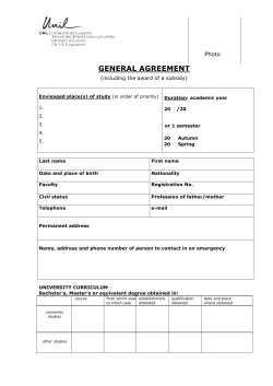


© Copyright 2026