
Design Manual for Thermoelectric Systems Tellurex: discover what’s possible.
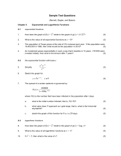
Design Manual for Thermoelectric Systems
Tellurex: discover what’s possible.
Tellurex offers a wide variety of products and services for your thermoelectric needs. Tellurex Plug
and play convenience means stock thermoelectric cooling engine assemblies that can speed you
though the design phase straight to proof of concept. Both cold plate and air to air systems are
available as well as temperature control options and power supplies. Tellurex further provides
engineering, design, and assembly services to get you from proof of concept to finished goods.
Visit our website: www.tellurex.com or call us at 231-947-0110 for design assistance.
Tellurex Corporation
www.tellurex.com
SA-10-FRM-00
Thermoelectric Cooling, Heating
When DC voltage is applied to the module, the positive and negative charge carriers in the pellet
array absorb heat energy from one substrate surface and release it to the substrate at the opposite
side. The surface where heat energy is absorbed becomes cold; the opposite surface where heat
energy is released, becomes hot. Using this simple approach to "heat pumping", thermoelectric
technology is applied to many widely-varied applications– small laser diode coolers, portable
refrigerators, scientific thermal conditioning, liquid coolers, and beyond.
Each individual thermoelectric system design will have a unique capacity for pumping heat (in
Watts or BTU/hour) and this will be influenced by many factors. The most important variables are
ambient temperature, physical & electrical characteristics of the thermoelectric modules employed,
and efficiency of the heat dissipation system (i.e., sink). Typical thermoelectric applications will
pump heat loads ranging from several milliwatts to hundreds of watts.
The Thermoelectric "Sweet Spot"
The majority of practical applications for thermoelectric technology fall within a very narrow
range of operating conditions.
•
•
•
Temperature differential (Delta T) between 30°C and 50°C
Thermoelectric module current draw (l) between 70% and 80% of IMAX, and
Co-efficient of performance (COP) between 0.25 and 0.4.
Tellurex Corporation
www.tellurex.com
SA-10-FRM-00
1. Getting Started; Understand the Thermal loads: Active and Passive
To maintain a temperature difference between an object and the ambient environment, a certain
amount of energy must be continually moved out of (for cooling) or into (for heating) the object.
The rate at which this energy is moved (usually expressed in watts), is the thermal load expressed
as Q.
In designing a thermoelectric system one of the most important processes is reaching an
understanding of your thermal load. You must have this information to select the thermoelectric
device and heat exchangers for the job. To start you need to arrive at a good, solid estimate of how
much thermal load must be removed from the object to achieve the performance objectives.
Examples of active, passive and combination of the two are:
Active only: a specific electrical device is producing heat while in operation and needs to be cooled.
The cooling system will be in direct contact with the device, the only significant source of heat will
be that specific device.
Passive only: a cup-holder in the center console of an automobile contains a bottle of water, the
only significant source of heat is the atmosphere surrounding the cup-holder.
Combination of active and passive load: An enclosure containing electrical equipment needs to
be kept at a certain temperature for the equipment to function properly. The electrical equipment
inside the box is a source of heat. The atmosphere surrounding the enclosure is warmer than the
desired internal temperature and is also a source of heat.
The active load portion is easily conceived; the passive load is like a leaky boat. Water is continually
leaking into the boat and you have to bail out the water to stay afloat. With a thermoelectric system,
you are trying to keep your thermal load colder than the ambient temperature; you have to bail out
the heat faster than it is leaking in. In cooling applications Heat is going to leak into the thermal
load from the ambient environment through the insulation, doors, seals and pass-through.
Worst Case Scenario Design: Determine what the highest ambient temperature and the desired
cold temperature. This is generally your worst case. If you design your system so that you'll have
enough cooling capacity in that worst case, you'll have more than enough potential for every other
situation. The worst-case difference between your ambient and load temperatures, will be your
'Delta T' in the equations which follow.
Passive Load Determination
If your system is an active load only you may skip this section. If you have a passive load element
this section will help you estimate that load.
The transfer of heat from a load to the ambient environment, is largely a function of two thermal
processes—conduction and convection. Conduction is the transfer of heat through matter
(insulation, structural components, seals, fasteners, etc.) and is a function of the temperature
difference (i.e., Delta T) across the material, the physical dimensions, and the thermal conductivity
Tellurex Corporation
www.tellurex.com
SA-10-FRM-00
of the material (K). Convection is heat transfer across the boundary layer of air at the surface of a
material. It is a function of the Delta T across the boundary layer and the rate of air movement at
the surface—the faster the air movement, the greater the convection of heat.
With a well-insulated thermal load (e.g., an insulated enclosure), convection is a relatively
inconsequential component and you can often focus exclusively on the conductive element. The
following equation can be used to estimate a purely conductive load:
(Purely conductive passive load equation)
Where
Q is the amount of heat conducted (it can be expressed in either BTU/hour or watts, although in
the thermoelectric industry, most support documentation is based on wattage);
∆T is the temperature difference between the thermal load and the ambient environment (in F° for
BTU/hour calculations, in C° for watts);
K (Kappa) is the thermal conductivity of the material expressed in either BTU/hour-feet-F° or
watts/meter-C°;
L is the thickness of the material (in feet for BTU/hour calculations, meters for watts); and
A is the exposed surface area of the material (in square feet for BTU/hour calculations, square
meters for watts).
If you want to include both the conductive and convective components of the load, you can use
this equation:
(Combination conductive/convective passive load equation)
where
Q is the amount of heat conducted and convected (expressed in either BTU/hour or watts);
K (Kappa) is the thermal conductivity of the material expressed in either BTU/hour-feet-F° or
watts/meter-C°;
h is the heat transfer coefficient (in still air, this ranges between 4-5 BTU/hour-feet2-F° or 23-28
watts/meter2-C°; in turbulent air, h falls in the range of 14-20 BTU/hour-feet2-F° or 85-113
watts/meter2-C°);
L is the thickness of the material (in feet for BTU/hour calculations, meters for watts);
A is the exposed surface area of the material (in square feet for BTU/hour calculations, square
meters for watts); and
∆T is the temperature difference between the thermal load and the ambient environment (in F° for
BTU/hour calculations, in C° for watts).
Note that the result that you get for Q with this equation will be lower than that obtained for the
formula based only upon conduction. This is because the convection/conduction equation accounts
Tellurex Corporation
www.tellurex.com
SA-10-FRM-00
for two sources of thermal resistance to heat flow. With the calculation reflecting a slightly greater
series resistance to heat leakage, it logically follows that fewer watts will be indicated to compensate
for passive load.
When you are dealing with an un-insulated load, or an un-insulated portion of one (e.g., a cold
plate), then it becomes very important to explore the convective part of thermal load. In these
situations, convection may offer the primary resistance to the leakage of heat. Remember that in
some situations (e.g., an un-insulated enclosure), you will have air movement on both the inside
and outside; as a result, your Delta T will be split between the two boundary layers (based on the
relative convectivity of each). As you will find in using the equation below to estimate your
convective load, without insulation, you will need to pump a lot more wattage with your
thermoelectric system.
(Purely convective passive load equation)
where
Q is the amount of heat convected (expressed in either BTU/hour or watts);
h is the heat transfer coefficient (in still air, this ranges between 4-5 BTU/hour-feet2-F° or 23-28
watts/meter2-C°; in turbulent air, h
falls in the range of 14-20 BTU/hour-feet2-F° or 85-113 watts/meter2-C°);
A is the exposed surface area of the material (in square feet for BTU/hour calculations, square
meters for watts); and
∆TB is the temperature difference across the boundary layer at any exposed surfaces (in F° for
BTU/hour calculations, in C° for watts).
When dealing with enclosures, you can also estimate your passive load empirically once a prototype
is built. Simply place a known heat load inside (make sure that the enclosure can 'take the heat'),
then monitor the temperatures of the ambient and enclosure interior. Once the Delta T between the
inside and ambient has stabilized, you can use the following equation to determine the passive load:
where
Q is the passive load, expressed in watts;
TAMB is the ambient temperature after stabilization (in C°);
TENC is the enclosure temperature after stabilization (in C°);
∆TDES is the desired temperature difference between the inside of the enclosure and the ambient
environment (in C°); and
P is the power dissipation within the heater employed for the test (expressed in watts).
Tellurex Corporation
www.tellurex.com
SA-10-FRM-00
2. Thermoelectric System Design
Taking an active load example of a specific electrical device that is producing heat while in
operation given above. The cooling system will be in direct contact with the device, the only
significant source of heat will be that specific device. That device has been found to be a 20 watt
device that works best at 20°C.
Q = 20 watt heat load arrived at through the exercises above.
TA = 35°C maximum ambient air temperature
TC = 20°C required temperature of electronic component
Prior to using the performance graphs to determine which thermoelectric module is appropriate
for our application, we must first identify the hot side temperature (TH) and the resultant
temperature differential across the module (∆T).
In this design, we will keep the rise of the heat sink temperature to no more than about 15°C
above ambient (this is a good rule of thumb heat sink rise). This would give us a thermoelectric
module hot side temperature of about 50°C.
TH = TA + heat sink rise above ambient = 25°C + 15°C = 50°C
The temperature differential across the module can now be calculated as follows:
∆T = TH - TC= 50°C – 20°C = 30°C
Module selection: The performance graphs for each of the modules provide data for hot side
temperature of 27°C and 50°C. For this application, use the Thot = 50°C curves.
Figure 1 Q v. Voltage under various Delta T
Tellurex Corporation
www.tellurex.com
SA-10-FRM-00
Figure 2 Voltage v. DT under various currents
The specification sheets indicate that a C2-40-1504 module is capable of meeting the needs. On
Figure 1 follow the 30°C delta t line (teal) until it intersects the 20 watt Y axis lines. The intersection
is slightly below the 11 volt level. This indicates some extra capacity if a 12 volt power supply is
used. Next, using figure 2, locate the intersection of the 11 volt Y axis level and the 30°C delta T
along the X axis. The intersection is very near the 3 amp line.
We can now approximate the thermoelectric module power using:
Power = I x V = 3 amps x 11 volts = 33 watts
Heat sink selection: The values identified in the preceding first pass analysis are used to assess
overall system feasibility. We want to qualify our assumption of 15°C rise across heat sink.
The hot side temperature will be equal to the ambient temperature (TA) plus the rise in temperature
across the heat sink from dissipating the heat load (Q) and the heat resulting from the thermoelectric
module electrical power (V x I).
TH = TA + (V x I + Q) RQ
where RQ = thermal resistance of heat sink in C° temperature rise per Watt dissipated.
The heat pumping capability of the thermoelectric module is significantly influenced by the
efficiency of the heat sink. The hot side of the module must interface with an efficient heat removal
system to achieve useful temperature differential across the thermoelectric module.
Natural convection, forced convection, and liquid cooled are three of the most common types of
heat sinks. Thermal resistance varies among the different types and sizes of sinks with natural
convection being the least efficient and liquid cooled the most efficient. The majority of
thermoelectric cooling applications use forced convection heat sinks with thermal resistance values
(RQ) ranging from 0.05°/W to 0.9°/W.
Using values now known for TA V, I, and Q we can solve for RQ to determine if it is reasonable:
Tellurex Corporation
www.tellurex.com
SA-10-FRM-00
RQ = (TH — TA)/(V x I +Q)=(50°C - 35°C)/(11V x 3 amps +20W)
RQ = 0.283°C/W
Our proposed system using a C2-40-1504 module and a forced convection sink/fan combination
meets or exceeds the criteria for this application.
3. System Assembly
Several methods for installing thermoelectric modules have been developed, including: mechanical
clamping, epoxy bonding, and direct solder bonding. The individual requirements of the application
will determine which method is most appropriate, mechanical clamping is by far the most common.
Thermoelectric modules are relatively strong in compression and weak in shear; whichever method
of installation is used, it is important to avoid excessive mechanical loading of the module.
Mechanical Clamping:
• Recommended flatness of interface surfaces should be within 0.001" and free of drit, burrs
etc.
• Thermal interface materials must be used to fill in the small thermal gaps
o Choices include silicone-based thermal grease, graphite foil, and thermallyconductive pads.
o Refer to your interface material specifications for performance curves in relation to
pressure.
• Bolt the object to be cooled and heat sink together using stainless steel fasteners washers
and or split type lock-washers, compression springs or Bellville washers can also be used.
• The recommended compression loading is 70 to 150 per sq. inch of module surface.
• Insure an even pressure across the module surface when tightening the screws.
Tellurex Corporation
www.tellurex.com
SA-10-FRM-00


© Copyright 2026