
WLAN Solution with Wireless LAN Module Demo Operation Manual
WLAN Solution
with Wireless LAN Module
Demo Operation Manual
32-BIT MICROCONTROLLER
FM4 Family
APPLICATION NOTE
Publication Number MB9B560R_AN709-00004
CONFIDENTIAL
Revision 1.0
Issue Date June 27, 2014
A P P L I C A T I O N
N O T E
Target products
This application note describes the following products.
Series Name
2
CONFIDENTIAL
Product Number
MB9B160R
MB9BF168M/N/R
MB9B360R
MB9BF368M/N/R
MB9B460R
MB9BF468M/N/R
MB9B560R
MB9BF568M/N/R
MB9B560R_AN709-00004-1v0-E, June 27, 2014
A P P L I C A T I O N
N O T E
Table of Contents
1.
2.
3.
4.
5.
6.
Introduction ..................................................................................................................................... 6
Wireless LAN Demo System .......................................................................................................... 7
2.1
System Configuration .......................................................................................................... 7
2.2
What is a Wireless LAN?..................................................................................................... 8
2.2.1
Connection Methods .......................................................................................... 9
2.2.2
Encryption Methods .......................................................................................... 10
2.2.3
Authentication Methods .................................................................................... 10
2.3
Overview of Demo System ................................................................................................ 12
2.3.1
Presetting the Demo ......................................................................................... 14
2.3.2
How to Start the Demo ..................................................................................... 15
2.3.3
Introduction of Demo Operations ...................................................................... 16
Hardware Overview ...................................................................................................................... 20
3.1
Hardware Configuration .................................................................................................... 20
3.2
Detailed Specifications ...................................................................................................... 22
Software Overview ....................................................................................................................... 25
4.1
Software Configuration ...................................................................................................... 25
4.1.1
OS Resources .................................................................................................. 26
4.1.2
File Structure .................................................................................................... 27
4.2
Detailed Specifications ...................................................................................................... 29
4.2.1
SDIO Card Compatible SD Driver .................................................................... 30
4.2.2
Wireless LAN Driver ......................................................................................... 36
4.3
Demo Software ................................................................................................................. 44
4.3.1
Configuration Settings ...................................................................................... 44
4.3.2
Web Server ...................................................................................................... 46
Other ............................................................................................................................................ 48
MAJOR CHANGES ...................................................................................................................... 49
June 27, 2014, MB9B560R_AN709-00004-1v0-E
CONFIDENTIAL
3
A P P L I C A T I O N
N O T E
Figure
Figure 2-1
Figure 2-2
Figure 2-3
Figure 2-4
Figure 2-5
Figure 2-6
Figure 2-7
Figure 2-8
Figure 2-9
Figure 2-10
Figure 2-11
Figure 2-12
Figure 2-13
Figure 2-14
Figure 2-15
Figure 2-16
Figure 2-17
Figure 3-1
Figure 3-2
Figure 3-3
Figure 3-4
Figure 3-5
Figure 3-6
Figure 3-7
Figure 3-8
Figure 3-9
Figure 3-10
Figure 4-1
Figure 4-2
Figure 4-3
Figure 4-4
4
CONFIDENTIAL
Wireless LAN Demo System Configuration ............................................................................ 7
History of IEEE 802.11 Standard ............................................................................................ 8
Infrastructure Mode ................................................................................................................ 9
Ad Hoc Mode .......................................................................................................................... 9
Micro AP Mode ....................................................................................................................... 9
Open Authentication (No Authentication)] ............................................................................. 10
WPA-PSK .............................................................................................................................. 11
WPA2-PSK ............................................................................................................................ 11
Demo system configuration .................................................................................................. 12
Main Screen ....................................................................................................................... 16
LED operation screen ......................................................................................................... 16
Operation using the switch on the FM4 evaluation board ................................................... 17
Operation using the LED operation page ........................................................................... 17
Example screen when green is ON .................................................................................... 18
Image scaling operation ..................................................................................................... 18
Screen transitions for image scaling operation ................................................................... 18
PDF file download .............................................................................................................. 19
Connection between FM4 evaluation board and wireless LAN module ................................ 20
FM4 evaluation board ........................................................................................................... 20
Wireless LAN module ........................................................................................................... 20
Overall hardware configuration during development ............................................................ 21
Hardware block diagram....................................................................................................... 21
Power supply interface ......................................................................................................... 23
Dedicated power cable ......................................................................................................... 23
SD card interface .................................................................................................................. 24
JTAG interface ...................................................................................................................... 24
ADC/SW interface .............................................................................................................. 24
Software module configuration ............................................................................................. 25
Configuration of start-up and tasks ....................................................................................... 26
Software schematic flow ....................................................................................................... 29
Creating the content file (fsdata.c) ........................................................................................ 46
MB9B560R_AN709-00004-1v0-E, June 27, 2014
A P P L I C A T I O N
N O T E
Tables
Table 2-1
Table 2-2
Table 2-3
Table 2-4
Table 2-5
Table 3-1
Table 4-1
Table 4-2
Table 4-3
Table 4-4
Table 4-5
List of demo system equipment ............................................................................................. 12
List of URLs ........................................................................................................................... 13
Wireless settings .................................................................................................................... 14
DHCP settings........................................................................................................................ 14
IP address settings................................................................................................................. 14
List of equipment used ........................................................................................................... 22
Tasks ...................................................................................................................................... 26
Other OS resources other than tasks ..................................................................................... 26
Configuration of lwIP .............................................................................................................. 44
Configuration of T-REALOS ................................................................................................. 44
Configuration of wireless LAN driver ...................................................................................... 45
June 27, 2014, MB9B560R_AN709-00004-1v0-E
CONFIDENTIAL
5
A P P L I C A T I O N
N O T E
1. Introduction
This demo operation manual describes the demo operations for controlling the wireless LAN module and
making a wireless LAN connection with a PC, smartphone and tablet utilizing the fast processing and SD
card interface functions of the FM4 family.
The fast processing of FM4 enables TCP/IP protocol stack processing and Web server functions in a
wireless LAN connection environment with only simple configuration of the FM4 and the wireless LAN
module.
When networking via wireless LAN with consumer equipment that is not connected to a network, or with
industrial equipment that is connected to a network via wired LAN, the challenge is to maintain the network
environment at low cost.
In order to address this challenge, it is necessary to minimize the costs for facilities and components and
study the most suitable system performance and features for applications.
We would like to encourage you to consider this solution as an idea for solving this challenge.
This demo operation manual describes a solution for performing network communication by installing a
wireless LAN module evaluation board made by TAIYO YUDEN CO., LTD. (hereafter called TAIYO YUDEN)
into an FM4-mounted board (SK-FM4-U120-9B560).
The part number of the FM4 mounted on the SK-FM4 U120-9B560 is the following.
• Part Number: MB9BF568R
*The photos of the wireless LAN module made by TAIYO YUDEN used in this document may differ from the
actual product.
Please consult TAIYO YUDEN CO.,LTD for details about the wireless LAN module.
The URLs given in this document are valid at the time of this writing. Those URLs are subject to change
without notice.
6
CONFIDENTIAL
MB9B560R_AN709-00004-1v0-E, June 27, 2014
A P P L I C A T I O N
N O T E
2. Wireless LAN Demo System
2.1
System Configuration
The following shows the system configuration of the wireless LAN demo system.
Overview
This demo system allows you to connect a device that has wireless LAN capability to the FM4 evaluation
board with wireless LAN module via an access point over a wireless LAN, to connect to the network from a
device running a Web browser to a Web server running on the FM4 evaluation board with wireless LAN
module, and to display contents, download files, and control the FM4 evaluation board.
Figure 2-1
June 27, 2014, MB9B560R_AN709-00004-1v0-E
CONFIDENTIAL
Wireless LAN Demo System Configuration
7
A P P L I C A T I O N
2.2
N O T E
What is a Wireless LAN?
This section describes a wireless LAN.
“Wireless LAN” refers to a LAN (Local Area Network) that transmits/receives data via wireless
communication.
It is no exaggeration to say that wireless LAN is the IEEE 802.11 standard, because IEEE 802.11-related
products are so pervasive at present.
The transmission rate of wireless LAN is dramatically improving as technology advances.
Figure 2-2
History of IEEE 802.11 Standard
160
IEEE 802.11n 40MHz/ch (*1)
140
Mbps
120
100
80
IEEE 802.11g
60
IEEE 802.11n 20MHz/ch (*1) (*2) (*3)
IEEE 802.11n 20MHz/ch (*1) (*2)
40
20
IEEE 802.11
IEEE 802.11b
0
1997
1999
2003
2009
[Year]
*1: For IEEE 802.11n, the transmission rate increases with the number of MIMOs (antennas).
*2: At IEEE 802.11n 20 MHz, the transmission rate depends on the GI (Guard Interval) value.
*3: This wireless LAN demo system is set to 20 MHz/ch GI = 400 ns.
The following transmission standards for wireless LAN are supported by this wireless LAN demo system.
− IEEE 802.11b
− IEEE 802.11g
− IEEE 802.11n
The following security standards for wireless LAN are supported by this wireless LAN demo system.
− IEEE 802.11 (WEP)
− IEEE 802.11i draft (WPA-PSK)
− IEEE 802.11i (WPA2-PSK)
Wireless LAN uses the 2.4 GHz band, but the number of available channels varies by country.
This wireless LAN demo system is regulated to use ch11 for use in the United States.
8
CONFIDENTIAL
MB9B560R_AN709-00004-1v0-E, June 27, 2014
A P P L I C A T I O N
2.2.1
N O T E
Connection Methods
This section describes modes that are available on this demo system as methods of connecting through
wireless LAN.
[Infrastructure Mode]
Method by which data communication is performed between wireless LAN devices via a repeater called
an access point.
With this method, a wireless LAN device connects to the access point first and then establishes a wireless
transmission path regardless of whether there is another party to perform data communication with.
Figure 2-3
Infrastructure Mode
[Ad Hoc Mode]
Method by which data communication is performed between wireless LAN devices directly.
With this method, it is not necessary to install an access point.
This mode uses standards up to 11b. It is not regulated by the 11g or 11n standards, and is used as a
vendor-dependent function.
Figure 2-4
Ad Hoc Mode
[Micro AP Mode]
Method by which wireless LAN devices that have access point capability connect via P2P and perform
data communication directly.
Although the name of this mode may differ depending on the company, it shall be called Micro AP mode in
this document.
With this method, it is not necessary to install an access point.
Figure 2-5
June 27, 2014, MB9B560R_AN709-00004-1v0-E
CONFIDENTIAL
Micro AP Mode
9
A P P L I C A T I O N
2.2.2
N O T E
Encryption Methods
This section describes the modes that are available on this demo system as encryption methods for
securing a wireless LAN.
[WEP]
WEP is an encryption method based on the RC4 encryption algorithm. Currently, serious vulnerabilities have
been found in WEP, so it should not be used.
WEP has a 40-bit mode and a 10-bit mode. These key sizes are fixed (5 and 13 characters, respectively).
[TKIP]
TKIP is an encryption method based on the RC4 encryption algorithm. Although it corrects the vulnerabilities
that exist in WEP, it is equivalent to WEP as an encryption method. If available, AES-CCMP, which is
described in the next section, should be used.
TKIP generates a PMK (256-bit) from a passphrase of any length specified by the user (max. 32 bytes in this
wireless LAN demo system), and uses it as the material for keys.
[AES-CCMP]
AES-CCMP is an encryption method based on the AES encryption algorithm. AES-CCMP is designated as
the standard encryption algorithm of the United States.
On the setting screen of the wireless LAN equipment, it is often displayed as "CCMP", "AES-CCM", or
simply "AES".
The method of generating the passphrase and PMK in AES-CCMP is the same as TKIP.
2.2.3
Authentication Methods
This section describes the modes that are available on this demo system as authentication methods for
securing a wireless LAN.
[Open Authentication (No Authentication)]
Figure 2-6
Open Authentication (No Authentication)]
This method is also called Open System authentication. This always returns “authentication successful” to
authentication requests from wireless LAN equipment. Basically, there is no authentication.
Note that the Open Authentication is used when WEP is used as the encryption method. Shared-key
authentication used to be designated as the authentication method for WEP. However, since a
man-in-the-middle attack vulnerability that compromises security has been found in this method, no
authentication is recommended now (However, using WEP is not recommended).
Therefore, Shared-key authentication is not supported by this wireless LAN demo system.
10
CONFIDENTIAL
MB9B560R_AN709-00004-1v0-E, June 27, 2014
A P P L I C A T I O N
N O T E
[WPA-PSK]
Figure 2-7
WPA-PSK
WPA-PSK is the authentication method that was released in the IEEE 802.11i draft. It is an interim measure
until WPA2 is specified.
In terms of encryption methods, you can choose between TKIP and AES-CCMP. In WPA-PSK, support for
TKIP is required. On the other hand, support for AES-CCMP is not required.
[WPA2-PSK]
Figure 2-8
WPA2-PSK
WPA2-PSK is the authentication method that was established by IEEE 802.11i. Since the interim measure of
WPA-PSK has been officially defined, WPA2-PSK is the same as WPA-PSK, basically. However, there is no
compatibility between them due to changes to the defined values.
WPA2-PSK requires support for AES-CCMP, but not TKIP.
If there are no restrictions on companion equipment, it is recommended to use WPA2-PSK plus AES-CCMP.
June 27, 2014, MB9B560R_AN709-00004-1v0-E
CONFIDENTIAL
11
A P P L I C A T I O N
2.3
N O T E
Overview of Demo System
As an overview of the demo system, this section describes the demo system configuration, setting
procedure, and introductory operations.
The description in this section assumes that a demo program has been written on the FM4 evaluation board.
Demo system configuration
Figure 2-9
Demo system configuration
List of equipment
Table 2-1
No.
1
2
Name
List of demo system equipment
Maker
Qty.
FM4 evaluation board
SPANSION
1
Wireless LAN module
TAIYO
evaluation board
YUDEN
1
3
Access point
BUFFALO
1
4
Battery
ELECOM
1
5
USB cable
-
1
6
Dedicated power cable
-
1
7
USB hub
-
1
-
1
-
1
8
9
Web browser device
(Android tablet)
Web browser device
(smartphone)
Description
FM4 evaluation board with mounted FM4 MCU and SD card slot.
(SK-FM4-U120-9B560)
Wireless LAN module evaluation board with SDIO interface.
(WBSAAVDX7)
Wireless LAN access point with DHCP server functions. (WMR-300)
Battery for FM4 evaluation board, wireless LAN module, and access
point. (DE-M01L-3530BK)
USB cable with Type A male - MiniB male connectors for 5V feed to
the FM4 evaluation board.
Dedicated power cable for 5 V feed to the wireless LAN module.
USB hub for 5 V feed to the FM4 evaluation board and the wireless
LAN module.
Used for displaying demo contents.
Used for displaying demo contents.
Note: The equipment for No.3 to No.9 is not manufacturer-specific.
Web content
12
CONFIDENTIAL
MB9B560R_AN709-00004-1v0-E, June 27, 2014
A P P L I C A T I O N
N O T E
List of URLs for Web content set on the FM4 evaluation board.
Table 2-2
List of URLs
Page overview
http://192.168.1.100/index.html
LED operation
http://192.168.1.100/ledctrl.cgi
PDF
http://192.168.1.100/SIL.pdf
June 27, 2014, MB9B560R_AN709-00004-1v0-E
CONFIDENTIAL
URL
Main
13
A P P L I C A T I O N
2.3.1
N O T E
Presetting the Demo
To run the demo system, the wireless settings and IP address settings required for the demo program must
be set in the access point.
The following shows the access point settings and the Web browser device settings.
<Access point settings>
[Wireless settings]
The following shows wireless settings for the demo program.
Table 2-3
Wireless settings
Item
Description
Channel
Automatic
SSID
FM4-WLAN_demo
Authentication
None
Encryption
None
Please set the wireless settings on the access point setting screen according to these settings.
Note: Since these settings are not encrypted, it is possible to connect by only selecting the SSID.
[DHCP settings]
Please enable DHCP to assign an IP address to the Web browser device.
The following shows the settings.
Table 2-4
Start IP
192.168.1.101(*)
DHCP settings
Number of units
Lease duration
64
1 hour
*Set this so that 192.168.1.100 can be excluded since it is used on the FM4 evaluation board.
[IP address settings]
In the demo program, the IP address of the FM4 evaluation board is fixed at 192.168.1.100.
For this reason, the access point must be set to the IP address of the network group corresponding to the IP
address of the FM4 evaluation board.
The IP addresses assumed for each piece of equipment are as follows.
Table 2-5
IP address settings
Equipment
IP address
Access point
192.168.1.1
FM4 evaluation board
192.168.1.100
Web browser terminal
Obtained by DHCP
<Web browser device settings>
Please enable DHCP.
14
CONFIDENTIAL
MB9B560R_AN709-00004-1v0-E, June 27, 2014
A P P L I C A T I O N
2.3.2
N O T E
How to Start the Demo
The following shows the procedure for starting the demo.
Note: Be sure to follow the procedure below to turn the power on.
Please disconnect the access point and the USB hub from the battery before starting the procedure.
Also disconnect the USB cable and dedicated power cable from the USB hub.
1.
Turn on the access point
− Turn on the battery and connect the access point to the battery to turn the power on.
− Find the preset SSID for the access point from the Web browser device.
− Connect the Web browser device to the access point with the above SSID.
2.
Turn on the wireless LAN module
− Connect the wireless LAN module to the SD card slot of the FM4 evaluation board.
− Connect the dedicated power cable to the USB hub.
− Connect the USB hub to the battery to turn on the wireless LAN module.
3.
Turn on the FM4 evaluation board
− Connect the USB cable to the USB hub to turn on the FM4 evaluation board.
− The LED on the evaluation board lights up in red during initialization.
*Once the LED flashes in red, the initialization is complete and it searches for the access point. If this
state continues for a long time, please review the settings for the access point.
− When the Web server starts and can be accessed from the Web browser device, the LED on the
evaluation board will repeatedly flash on and off five times and then turn off.
4.
Access from Web browser device
− Make sure that the FM4 evaluation board is accessible before accessing it from the Web browser
device.
− Please refer to Table 2-2
June 27, 2014, MB9B560R_AN709-00004-1v0-E
CONFIDENTIAL
for the URLs that are accessible.
15
A P P L I C A T I O N
2.3.3
N O T E
Introduction of Demo Operations
The following three demos are provided.
Demo 1: Changing the LED Status
Demo 2: Scaling an Image
Demo 3: Downloading a PDF
Each demo is shown below.
[Demo screen configuration]
Figure 2-10
Figure 2-11
16
CONFIDENTIAL
Main Screen
LED operation screen
MB9B560R_AN709-00004-1v0-E, June 27, 2014
A P P L I C A T I O N
N O T E
[Demo 1: Changing the LED Status]
In Demo 1, the LED status is reflected in the Web browser.
There are two ways to turn LED lights on/off.
1.
Operation using the switch on the FM4 evaluation board
− Each time the "SW2" switch (middle of three switches) is pressed on the FM4 evaluation board, the
LED repeatedly turns on/off in the following pattern.
Figure 2-12
Operation using the switch on the FM4 evaluation board
Note: SW1, which is next to SW2, is "Reset".
If SW1 is pressed by mistake, restart the system according the procedure for starting the
demo.
2.
Operation using the LED operation page
− The LEDs on the board can be operated from the "LED Operation" page in the URL list.
Figure 2-13
Operation using the LED operation page
− Click the ON button for each color to light the LED in the corresponding color (in any combination).
− The ON button for the color set to ON cannot be operated, and the OFF button becomes operable
instead.
− To turn the LED light off, click the OFF button.
June 27, 2014, MB9B560R_AN709-00004-1v0-E
CONFIDENTIAL
17
A P P L I C A T I O N
N O T E
Show the Web browser screen example with an operation.
Figure 2-14
Example screen when green is ON
[Demo 2: Scaling an Image]
In Demo 2, a brochure for the demo is scaled up/down through analog input on the board.
By using the "blue dial" on the evaluation board, the image on the browser is scaled up/down according to
the state of the analog input value.
Figure 2-15
Figure 2-16
18
CONFIDENTIAL
Image scaling operation
Screen transitions for image scaling operation
MB9B560R_AN709-00004-1v0-E, June 27, 2014
A P P L I C A T I O N
N O T E
[Demo 3: Downloading a PDF]
In Demo 3, a PDF file of the image displayed in Demo 2 can be downloaded.
To view the downloaded PDF file, the Web browser requires software for viewing PDF files.
Please refer to Table 2-3
for the wireless LAN configuration of the Web browser terminal.
There are two methods for downloading the file.
1.
Directly enter the URL in the Web browser
Directly enter the URL of the PDF in the List of URLs into the address entry field.
2.
Click the link on the main screen of the demo
Figure 2-17
June 27, 2014, MB9B560R_AN709-00004-1v0-E
CONFIDENTIAL
PDF file download
19
A P P L I C A T I O N
N O T E
3. Hardware Overview
3.1
Hardware Configuration
The following shows the hardware configuration.
Configuration of FM4 evaluation board and wireless LAN module
[Connection between FM4 Evaluation Board and Wireless LAN Module]
Figure 3-1
Connection between FM4 evaluation board and wireless LAN module
FM4(MB9B560)
SDIO Interface
Wireless LAN Module
[FM4 Evaluation Board]
Figure 3-2
FM4 evaluation board
Figure 3-3
Wireless LAN module
[Wireless LAN Module]
20
CONFIDENTIAL
MB9B560R_AN709-00004-1v0-E, June 27, 2014
A P P L I C A T I O N
N O T E
Overall hardware configuration during development
Figure 3-4
Overall hardware configuration during development
Hardware block diagram
This section describes the hardware for linking and operating the FM4 and wireless LAN module together.
− WLAN module
The FM4 and the wireless LAN module communicate with each other via an SDIO interface. The FM4
operates based on the SDIO specification using the SD Host function of the SD card Interface.
− IAR J-Link ICE
The FM4 evaluation board and the IAR J-Link ICE are connected by a 20-pin JTAG interface, and the
PC and IAR J-Link ICE are connected by a USB cable.
This is used for writing to the internal Flash on the FM4 and debugging programs.
Using this requires the IAR Embedded Workbench.
− Regulated DC Power Supply
Connect a power supply that can output DC 5 V.
Figure 3-5
June 27, 2014, MB9B560R_AN709-00004-1v0-E
CONFIDENTIAL
Hardware block diagram
21
A P P L I C A T I O N
3.2
N O T E
Detailed Specifications
This section shows the detailed specifications of the hardware.
List of equipment used during development
Table 3-1
No.
1
Name
FM4 evaluation board
List of equipment used
Manufacturer
Part number
SPANSION
SK-FM4-U120-9B560
Description
FM4 evaluation board body.
A Wireless LAN module evaluation board.
2
Wireless LAN module
evaluation board
TAIYO YUDEN
WBSAAVDX7
Note: Red and blue power cables are included when
purchasing this module.
This is for supplying power to the wireless LAN
module evaluation board. Use a power supply that
can output DC 5 V.
Note: The 5 V power can be supplied by using a
3
Stabilized power supply
-
-
dedicated power cable instead of the stabilized
power supply.
Creating a dedicated power cable is at your own
risk.
This is used for writing and debugging programs.
4
IAR J-Link ICE
IAR
J-Link-ARM
Note: JTAG and USB cables are included when
purchasing this ICE.
A PC that runs IAR Embedded Workbench is
required.
Up to 3 USB ports are used.
5
PC
-
-
1st: Supplies power to the FM4 evaluation board.
2nd: Connects with J-Link.
3rd: Supplies power to the wireless LAN module.
Use a USB cable with [Type A male] - [MiniB
male] connectors.
6
USB cable
-
-
This is for supplying power to the FM4 evaluation
board.
22
CONFIDENTIAL
MB9B560R_AN709-00004-1v0-E, June 27, 2014
A P P L I C A T I O N
N O T E
Built-in components
The built-in components are shown below.
[FM4 Evaluation Board]
Please refer to the following Web site.
http://www.spansion.com/Support/microcontrollers/developmentenvironment/Pages/board-SK-FM4-U120
-9B560.aspx
[Wireless LAN Module]
Please refer to the following Web site.
https://www.yuden.co.jp
Please refer to the documentation included at the time of purchase.
Interfaces used
The following shows the interfaces used on each board.
[Power Supply]
Figure 3-6
Power supply interface
Figure 3-7
Dedicated power cable
This hardware requires supplying both, the FM4 evaluation board, and the Wireless LAN module
evaluation board with 5 V power, individually.
Power is supplied to the FM4 evaluation board by connecting it to the PC with a USB cable.
Power is supplied to the wireless LAN module evaluation board by connecting it to the stabilized power
supply.
The power source is 5 V. You can create a dedicated power cable to supply the power.
June 27, 2014, MB9B560R_AN709-00004-1v0-E
CONFIDENTIAL
23
A P P L I C A T I O N
N O T E
[SD Card Interface]
Figure 3-8
SD card interface
The SD card slot uses a push-on/push-off mechanism. When inserting or removing the SD card, push it in
once as far as possible.
[JTAG Interface]
Figure 3-9
JTAG interface
A 20-pin JTAG interface connecting with IAR J-Link ICE.
[ADC/SW Interface]
Figure 3-10
ADC/SW interface
The ADC interface is used for scaling the demo display and is a dial type.
A SW interface is used for changing the LED display in the demo and is a push type.
24
CONFIDENTIAL
MB9B560R_AN709-00004-1v0-E, June 27, 2014
A P P L I C A T I O N
N O T E
4. Software Overview
4.1
Software Configuration
The following shows the software configuration.
Overview
The software for this demo system operates on the Real Time OS (RTOS) and runs the demo application
using a TCP/IP protocol stack, wireless LAN driver, and peripheral driver for FM4 family as a platform.
Block diagram
The software components are shown as a hierarchical image.
Figure 4-1
Software module configuration
[Application]
lwIP-contrib 1.4.1 is used as the Web server function.
[TCP/IP]
lwIP STABLE-1.4.1 is used as the TCP/IP protocol stack.
[RTOS]
T-REALOS/M4F for EWARM is used as the Real Time OS.
[PDL and SDIO Driver In PDL]
PDL Project for FM4 Family ver 1.0 and an SDIO driver enhanced for this demo system are used as
the FM4 peripheral device drivers.
[WLAN Driver]
This communicates with the wireless LAN module via the SDIO interface to control the wireless LAN
module.
Since the contract prohibits disclosure of the source code, this is provided in a library format.
June 27, 2014, MB9B560R_AN709-00004-1v0-E
CONFIDENTIAL
25
A P P L I C A T I O N
4.1.1
OS Resources
Figure 4-2
Configuration of start-up and tasks
Table 4-1
Priority
Task name
Wireless LAN driver
10
N O T E
Tasks
Stack
Processes
size (bytes)
4096 (*)
The main task of the wireless LAN driver.
task
It controls transmission and reception for the wireless LAN module.
20
TCP/IP stack task
29
TCP/IP event task
4096 (*)
The main task of TCP/IP stack.
It performs TCP/IP protocol processing.
4096 (*)
After starting the TCP/IP stack, it waits for an event notification from the
wireless LAN driver and then starts processing the corresponding TCP/IP
stack.
30
Application task
40
Idle task
98
Initial task
4096 (*)
The main user task.
It calls each initialization process.
256 (*)
Task for idle processing of RTOS. Basically, no processing is performed. Do
not remove this.
1024 (*)
Initial startup task of RTOS.
*: Stack size of each task is not optimized.
Table 4-2
Other OS resources other than tasks
Task name
Wireless LAN driver task
Used resources
Event flag x 1, Mailbox x 1
Mutex (*)
TCP/IP stack task
Semaphore (*)
Message buffer (*)
TCP/IP event task
Event flag x 1
Application task
No used resource
Idle task
No used resource
Initial task
No used resource
*: The resources used by the TCP/IP stack task are dynamically called from lwIP. Therefore, the
number of used resources varies depending on the function that is operating. In this wireless
LAN demo system, the maximum number specified in the configuration is sufficient. If you want
to expand the function, adjust the maximum number in the configuration.
26
CONFIDENTIAL
MB9B560R_AN709-00004-1v0-E, June 27, 2014
A P P L I C A T I O N
4.1.2
N O T E
File Structure
The file structure of this application is shown below.
Some files that have not been modified and directories that have no modified files are omitted.
+---app
: User-added implementation directory
+---pdl_user.h
: FM4 PDL configuration header file
+---user_main.c
: User main source file
+---user_main.h
: User main header file
+---fm4
: FM4-PDL directory
+---common
+---base_types.h
: Basic common header file
+---mb9abxxx.h
: Peripheral definition header file
+---mcu.h
: MCU common header file
+---system_mb9abxxx.c
: System setting source file
+---system_mb9abxxx.h
: System setting definition header file
+---library
+---driver
: PDL library directory
: PDL core driver directory
+---interrupts.c
: PDL interruption handler source file
+---sd
: SD card interface driver directory
+---sd.c
: SD card interface driver source file
+---sd.h
: SD card interface driver header file
+---sd_cfg.h
: SD card interface driver configuration header file
+---highlevel
+---sd
: PDL high level driver directory
: SD high level driver directory
+---sdcard.c
: SD memory card processing source file
+---sdcard.h
: SD memory card processing header file
+---sdcmd.c
: SD command common processing source file
+---sdcmd.h
: SD command common processing header file
+---sdiocard.c
: SDIO card processing source file
+---sdiocard.h
: SDIO card processing header file
+---lwip
: Core directory of lwIP software
+---lwip_contrib
: Peripheral directory of lwIP software
+---apps
+---httpserver_raw
: Application protocol directory of lwIP software
: lwIP HTTP server directory
+---fsdata.c
: Content C language source file
+---httpd_structs.h
: HTTP header string definition file
+---sample_demo_contents
: Content C language source generation directory
+---fs
+---lwip_usr
+---ports
+---fm4
June 27, 2014, MB9B560R_AN709-00004-1v0-E
CONFIDENTIAL
: FM4-PDL common directory
: Demo content stored directory
: User implementation directory of lwIP software
: User implementation directory
: FM4 implementation directory
27
A P P L I C A T I O N
+---ajax.c
: lwIP HTTP server AJAX processing source file
+---app_lwip.c
: lwIP application implementation part
+---ethif.c
: lwIP I/O-related low level implementation part
+---sys_arch.c
: lwIP architecture-dependent low level implementation part
+---include
: lwIP include directory
+---app
: lwIP HTTP server AJAX processing header file
+---app_lwip.h
: lwIP application implementation header file
+---ethif.h
: lwIP I/O-related low level implementation header file
: lwIP architecture implementation-related include directory
+---cc.h
: lwIP architecture environment definition file
+---lwipopts.h
: lwIP option definition file
+---perf.h
: lwIP perf-related header file
+---sys_arch.h
: lwIP architecture-dependent low level implementation header file
+---proj
: Development environment project directory
+---IAR
+---config
: Project directory for IAR (JTAG)
: configuration file directory
+---mb9bf568.icf
: Linker setting file
+---reset.mac
: Startup macro file
+---flashloader
: Flash loader directory
+---FlashLoader.board
: Flash loader setting file specification file
+---FlashMB9B560.flash
: Flash loader setting file
+---FlashMB9B560.flash
: Flash loader startup macro file
+---FlashMB9B560.out
: Flash loader body
+---wlan_release.ewd
: Project setting file
+---wlan_release.ewp
: Project file
+---wlan_release.eww
: Workspace file
+---utrealos
: T-REALOS directory
+---utrealos_usr
: T-REALOS user implementation directory
+---icrt0.asm
: Startup file
+---os.c
: T-REALOS low level implementation source file
+---os.h
: T-REALOS low level implementation header file
+---startup_mb9xfxxx.s
: Interrupt vector definition file
+---cfg
: T-REALOS configuration directory
+---config.a
: T-REALOS configuration file
+---wlancfg.tcf
: T-REALOS configuration definition file
+---wlanlib
CONFIDENTIAL
: lwIP application implementation-related include directory
+---ajax.h
+---arch
28
N O T E
: Wireless LAN driver library directory
+---wlan.h
: Wireless LAN driver library header file
+---wlan_conf.c
: Wireless LAN driver configuration source file
+---wlanlib.a
: Wireless LAN driver library file
MB9B560R_AN709-00004-1v0-E, June 27, 2014
A P P L I C A T I O N
4.2
N O T E
Detailed Specifications
The following shows the detailed specifications.
Operation and schematic flow
Figure 4-3
Software schematic flow
API Specification
<T-REALOS>
Please refer to the T-REALOS documentation.
<lwip protocol stack>
Please refer to the lwIP.
URL of the lwIP official project is:
http://savannah.nonqnu.org/projects/lwip/
The lwIP consists of two packages. "lwip" includes a TCP/IP stack developed in the official project, and
"contrib" includes additional code.
June 27, 2014, MB9B560R_AN709-00004-1v0-E
CONFIDENTIAL
29
A P P L I C A T I O N
N O T E
<RDL>
Please refer to the PDL documentation.
The PDL documentation is contained in the compressed file of the Peripheral Driver Library downloaded
from the following URL.
http://www.spansion.com/Support/microcontrollers/sampleprogram/Pages/fm4.aspx
The SD driver has been enhanced to support the SDIO card.
The API of the enhanced SD drive is explained in 4.2.1 SDIO Card Compatible SD Driver.
<Wireless LAN driver>
The API of the wireless LAN driver is explained in 4.2.2 Wireless LAN Driver.
4.2.1
SDIO Card Compatible SD Driver
Structure definition
Item
Description
Overview
Callback setting information
Format
typedef struct stc_sd_config_cb {
func_ptr_sd_arg32_t pfnTxCallback;
func_ptr_sd_arg32_t pfnRxCallback;
func_ptr_sd_arg32_t pfnWakeupCallback;
func_ptr_sd_arg32_t pfnErrorCallback;
func_ptr_sd_arg32_t pfnCardIntCallback;
func_ptr_sd_arg32_t pfnErrorResponseCallback;
} stc_sd_config_cb_t;
Description
pfnTxCallback
: Callback function when Tx occurs (Not used)
pfnRxCallback
: Callback function when Rx occurs (Not used)
pfnWakeupCallback
: Callback function when Wakeup occurs (Not used)
pfnErrorCallback
: Callback function when Error occurs (Not used)
pfnCardIntCallback
: Callback function when Card Interrupt occurs
pfnErrorResponseCallback
: Callback function when command response error occurs
Remarks
30
CONFIDENTIAL
The settings for other than pfnCardIntCallback and pfnErrorResponseCallback are invalid.
MB9B560R_AN709-00004-1v0-E, June 27, 2014
A P P L I C A T I O N
N O T E
Item
Description
Overview
SDIO card information
Format
typedef struct stc_sdiocard_info {
en_sdio_init_type_t
init_type;
en_sdio_init_io_t
io_init;
en_sdio_init_mem_t
mem_init;
uint8_t
flg;
uint32_t
OCR;
uint16_t
RCA;
en_sdio_card_type_t card_type;
} stc_sdiocard_info_t;
Description
init_type
: Sdio Initialize Type
PowerOn
Power on
ReInitMemory
Re-init memory
ReInitIO
Re-init IO
io_init
: Select Sdio IO initialization
NotUseIO
Not use IO (Disable IO initialization)
UseIO
Use IO (Enable IO initialization)
mem_init
: Select Sdio memory initialization
NotUseMem
Not use memory (Disable memory initialization)
UseMem
Use memory (Enable memory initialization)
flg
: Initialization status flag
OCR
: Operation conditions register
RCA
: Relative card address
card_type
: Sdio card type
SDSC_MemOnly
SDSC memory-only card
SDHCXC_MemOnly
SDHC or SDXC memory-only card
SD_IOOnly SD IO-only card
SDSC_Combo
SDSC combo card
SDHCXC_Combo
SDHC or SDXC combo card
Remarks
June 27, 2014, MB9B560R_AN709-00004-1v0-E
CONFIDENTIAL
31
A P P L I C A T I O N
Item
N O T E
Description
Overview
DMA transfer information
Format
typedef struct stc_sdh_dma_info {
en_sd_card_type_t
sdc_type;
en_sdh_dma_type_t dma_type;
uint32_t
data_addr;
uint32_t
data_addr_h;
en_sd_boundary_t
sdma_bound;
} stc_sdh_dma_info_t;
Description
sdc_type
: SD card type
SDH_SD_CARD
SD memory card
SDH_SDIO_CARD
SDIO card
dma_type
: SD Host DMA type
SDH_SDMA
SDMA
SDH_ADMA
ADMA2
data_addr
: DMA data address
SDMA: Buffer address
ADNA2: Lower 32-bit address of descriptor
data_addr_h
: DMA data address (area for 64-bit system)
SDMA: Not necessary
ADNA2: Higher 32-bit address of descriptor
sdma_bound
: Boundary specification for SDMA
BOUND_4K
BOUND_8K
BOUND_16K
BOUND_32K
BOUND_64K
BOUND_128K
BOUND_256K
BOUND_512K
Remarks
About ADMA2 Descriptors
• The structure of one descriptor area is as follows.
Attribute information area (attr)[16-bit] + Data length area (len)[16-bit] + Data storage address (addr)[32-bit]
• Since attr is set automatically within the driver, set it to 0 in the caller.
• The descriptor area should be a continuous area as long as the attribute is not a link attribute.
• When setting a descriptor with a link attribute, set the len to 0.
Then, the area specified by the addr is the descriptor area.
• Make sure to add to the descriptor a descriptor for determining when to terminate.
For the descriptor that determines termination, set the len to 0 and the addr to 0 (NULL).
Descriptor example:
32
CONFIDENTIAL
MB9B560R_AN709-00004-1v0-E, June 27, 2014
A P P L I C A T I O N
N O T E
API list
[SD Card Interface Driver API]
API
Description
specification
Overview
Changes SD speed mode to High-Speed
Format
void Sd_HighspeedChange(void)
Input
None
Return value
None
Remarks
Call this API after initialization is completed if the card supports the High-Speed mode.
API
Description
specification
Overview
Sets the interrupt callback function
Format
en_result_t Sd_SetIntCallback(stc_sd_config_cb_t* pstcSdCbCfg)
Input
pstcSdCbCfg
: Pointer for callback setting information
(Please refer to the description of the structure for details of callback setting information)
Return value
Error codes
Ok
Remarks
Normal end (This API always returns Ok)
Call this API after Sd_HostInit() is called, if the interrupt callback function needs to be set.
The settings for other than pfnCardIntCallback and pfnErrorResponseCallback are invalid.
API
Description
specification
Overview
Enables CardInterrupt
Format
en_result_t Sd_EnableCardInt(volatile stc_sd_t *pstcSd)
Input
pstcSd
Return value
Error codes
: Pointer for SD card interface register information
Ok
Remarks
Normal end (This API always returns Ok)
Call this API if you want to enable CardInterrupt after Sd_HostInit() is called.
When pfnCardIntCallback is set with Sd_SetIntCallback,
the next CardInterrupt can be received by enabling the CardInterrupt with this API after the interruption process
is completed
API
Description
specification
Overview
Disables CardInterrupt
Format
en_result_t Sd_DisableCardInt(volatile stc_sd_t *pstcSd)
Input
pstcSd
: Pointer for SD card interface register information
Return value
Error codes
Ok
Remarks
Normal end (This API always returns Ok)
Call this API if you want to disable CardInterrupt after Sd_HostInit() is called.
June 27, 2014, MB9B560R_AN709-00004-1v0-E
CONFIDENTIAL
33
A P P L I C A T I O N
N O T E
[SDIO High-level Driver API]
API
Description
specification
Overview
Obtains insertion/removal status of SDIO card
Format
boolean_t
Input
None
Return value
Insertion/removal status
Remarks
Sdiocard_Detect(void)
TRUE
Inserted
FALSE
Removed
Call this API after Sd_HostInit() is called.
API
Description
specification
Overview
Initializes SDIO
Format
int32_t Sdiocard_Init(stc_sdiocard_info_t *pstcSdiocardInfo)
Input
pstcSdiocardInfo
Pointer to SDIO card information
(Please refer to the description of the structure for details of SDIO card information)
Return value
Remarks
Error codes
E_SDIO_OK
Normal end
E_SDIO_NO_CARD
Abnormal end (No SDIO card inserted)
E_SDIO_INIT
Abnormal end (Failed to initialize the SDIO card)
Call this API after Sd_HostInit() is called.
API
Description
specification
Overview
Transmits and receives CMD52 commands
Format
int32_t Sdiocard_Cmd52(stc_sdiocard_info_t *pstcSdiocardInfo,
const uint32_t* pu32arg, uint32_t* pu32res)
Input
pstcSdiocardInfo
Pointer to SDIO card information
(Please refer to the description of the structure for details of SDIO card information)
pu32arg
: Pointer to SDIO CMD52 argument
pu32res
: Pointer to SDIO CMD52 response storage area
Return value
Error codes
E_SDIO_OK
Normal end
E_SDIO_NO_CARD
Abnormal end (No SDIO card inserted)
E_SDIO_PARAMETER Abnormal end (Incorrect parameter)
Remarks
E_SDIO_WRITE
Abnormal end (Write operation failed)
E_SDIO_READ
Abnormal end (Read operation failed)
Call this API after Sdiocard_Init() is called.
This API transmits/receives CMD52 commands using the common SD command processing function,
Sdcmd_SendCmd.
34
CONFIDENTIAL
MB9B560R_AN709-00004-1v0-E, June 27, 2014
A P P L I C A T I O N
N O T E
API
Description
specification
Overview
Transmits and receives CMD53 commands (by PIO transfer)
Format
int32_t Sdiocard_Cmd53(stc_sdiocard_info_t *pstcSdiocardInfo,
const uint32_t* pu32arg, uint32_t* pu32res,
uint8_t* pu8buf)
Input
pstcSdiocardInfo
: Pointer to SDIO card information
(Please refer to the description of the structure for details of SDIO card
pu32arg
: Pointer to SDIO CMD53 argument
pu32res
: Pointer to SDIO CMD53 response storage area
pu8buf
: Pointer to transmission data or reception data storage area
Return value
Error codes
E_SDIO_OK
Normal end
E_SDIO_NO_CARD
Abnormal end (No SDIO card inserted)
E_SDIO_PARAMETER Abnormal end (Incorrect parameter)
Remarks
E_SDIO_WRITE
Abnormal end (Write operation failed)
E_SDIO_READ
Abnormal end (Read operation failed)
Call this API after Sdiocard_Init() is called.
This API transmits/receives CMD53 commands via PIO transfer using the common SD command processing
functions Sdcmd_SendCmd/Sdcmd_TxData/Sdcmd_RxData.
API
Description
specification
Overview
Transmits and receives CMD53 commands (by DMA transfer)
Format
int32_t Sdiocard_Cmd53_dma(stc_sdiocard_info_t *pstcSdiocardInfo,
const uint32_t* pu32arg, uint32_t* pu32res,
stc_sdh_dma_info_t *pstcDmaInf)
Input
pstcSdiocardInfo
: Pointer to SDIO card information
(Please refer to the description of the structure for details of SDIO card information)
pu32arg
: Pointer to SDIO CMD53 argument
pu32res
: Pointer to SDIO CMD53 response storage area
pstcDmaInf
: Pointer to DMA transfer information
(Please refer to the description of the structure for details of DMA transfer information)
Return value
Error codes
E_SDIO_OK
Normal end
E_SDIO_NO_CARD
Abnormal end (No SDIO card inserted)
E_SDIO_PARAMETER Abnormal end (Incorrect parameter)
Remarks
E_SDIO_WRITE
Abnormal end (Write operation failed)
E_SDIO_READ
Abnormal end (Read operation failed)
Call this API after Sdiocard_Init() is called.
This API transmits/receives CMD53 commands via DMA transfer using the common SD command processing
function, Sdcmd_SendCmd_dma.
When DMA transfer by ADMA2 is performed using this API, the caller must secure a descriptor area as well as
the DMA transfer information area and the DMA data area.
June 27, 2014, MB9B560R_AN709-00004-1v0-E
CONFIDENTIAL
35
A P P L I C A T I O N
4.2.2
N O T E
Wireless LAN Driver
Structure definition
Item
Description
Overview
OS resource information
Format
typedef struct wlan_os_resource {
PRI
itskpri;
void*
stk;
int32_t
stksz;
} WLAN_OS_RESOURCE;
Description
itskpri
: Priority of the wireless LAN driver task
stk
: Stack address of the wireless LAN driver task
stksz
: Stack size of the wireless LAN driver task
Remarks
In the configuration file, wlan_conf.c, define it as variable: wlan_os_resource_init.
Item
Description
Overview
Scatter/gather type
Format
typedef struct wlan_sg {
uint16_t
__reserved_1;
uint16_t
len;
void*
addr;
} WLAN_SG;
Description
len
: Length
addr
: Address
Remarks
Used in transmission API.
Item
Description
Overview
Callback definition
Format
typedef struct wlan_callback {
void
(*Recv)(uint32_t epbuf_len);
void
(*Event)(uint32_t event, void* data);
} WLAN_CALLBACK;
Description
Recv
: Receive callback function
Event
: Event callback function
Remarks
36
CONFIDENTIAL
In the configuration file, wlan_conf.c, define it as variable: wlan_callbackfunc.
MB9B560R_AN709-00004-1v0-E, June 27, 2014
A P P L I C A T I O N
N O T E
Item
Description
Overview
Connection configuration
Format
#define WLAN_SSID_LEN_MAX
32
#define WLAN_KEYLEN_MAX
32
typedef struct wlan_config {
uint8_t
ssid[WLAN_SSID_LEN_MAX];
uint32_t
ssid_len;
int
comm_mode;
int
auth_mode;
uint8_t
key[WLAN_KEYLEN_MAX];
uint32_t
key_len;
int
channel;
int
uap_wpa_cipher;
} WLAN_CONFIG;
Description
ssid
: SSID
ssid_len
: Length of SSID (automatic determination with 0)
comm_mode
: Connection method
WLAN_MODE_ADHOC
Ad hoc mode
WLAN_MODE_INFRASTRUCTURE
Infrastructure mode
WLAN_MODE_UAP
Micro AP mode
auth_mode
: Authentication mode
WLAN_AUTH_MODE_OPEN
No authentication
WLAN_AUTH_MODE_WEP
WEP (40-bit/104-bit)
WLAN_AUTH_MODE_WPA_PSK WPA/WPA2-PSK
key
: Key
key_len
: Length of key (automatic determination with 0)
WEP
Specify a five-character (40-bit) or 13-character (104-bit) key
WPA
Specify a passphrase of any length (max. 32 characters)
channel
: Channel (automatic detection with 0)
When specifying individually, set the value from ch1 to ch11.
uap_wpa_cipher
(Micro AP mode only. Otherwise, ignored)
: WPA encryption method
Remarks
WLAN_CIPHER_MIXED
AES-CCMP/TKIP mixed mode
WLAN_CIPHER_AES_CCMP
AES-CCMP
In the configuration file, wlan_conf.c, define it as variable: wlan_conf.
Set the destination or source information.
- AES-CCMP/TKIP mixed mode of uap_wpa_cipher
In this mode, TKIP is used as the group cipher. This means that support for TKIP is required even when
connecting using AES-CCMP.
Set the mode as follows to match the companion equipment.
• Equipment supporting only TKIP
->WLAN_CIPHER_MIXED
• Equipment supporting only AES-CCMP
->WLAN_CIPHER_MIXED
In a mode other than Micro AP mode, the WPA encryption method can be determined automatically.
June 27, 2014, MB9B560R_AN709-00004-1v0-E
CONFIDENTIAL
37
A P P L I C A T I O N
Item
N O T E
Description
Overview
Scan information
Format
#define WLAN_SSID_LEN_MAX
32
#define WLAN_BSSID_LEN
6
typedef struct wlan_scan {
uint8_t
ssid[WLAN_SSID_LEN_MAX];
uint32_t
ssid_len;
uint8_t
bssid[WLAN_BSSID_LEN];
int
comm_mode;
int
auth_mode;
int
channel;
uint8_t
rssi;
} WLAN_SCAN;
#define WLAN_SCANRESULT_MAX
16
typedef struct wlan_scanresult {
int
bss_num;
WLAN_SCAN
bss_info[WLAN_SCANRESULT_MAX];
} WLAN_SCANRESULT;
Description
ssid
: SSID
ssid_len
: Length of SSID
bssid
: BSSID
comm_mode
: Connection method
WLAN_MODE_ADHOC
Ad hoc mode
WLAN_MODE_INFRASTRUCTURE
Infrastructure mode
WLAN_MODE_UNKNOWN
Unknown
auth_mode
: Authentication mode
WLAN_AUTH_MODE_OPEN
No authentication
WLAN_AUTH_MODE_WEP
WEP (40-bit/104-bit)
WLAN_AUTH_MODE_WPA_PSK WPA/WPA2-PSK
channel
: Channel
rssi
: RSSI
bss_num
: Number of search results
The maximum number of search results is 16; results exceeding that number are dropped.
bss_info
: Array of search results
Remarks
38
CONFIDENTIAL
MB9B560R_AN709-00004-1v0-E, June 27, 2014
A P P L I C A T I O N
N O T E
API list
API
Description
specification
Overview
Initializes wireless LAN driver
Format
int wlan_start(void)
Input
None
Return value
Error codes
Remarks
DRIVER_OK
Normal end
DRIVER_ERR
Error stop
Call this first before using the API of the wireless LAN driver.
OS resources are generated by using information from variable wlan_os_resource_init, in configuration file
wlan_conf.c.
API
Description
specification
Overview
Starts of wireless LAN connection
Format
int wlan_connect(void)
Input
None
Return value
Error codes
Remarks
DRIVER_OK
Normal end
DRIVER_ERR
Error stop
The connection process is performed using information from variable wlan_os_resource_init in configuration
file wlan_conf.c.
It returns from the API before the connection process is completed.
When the connection is established, notification is provided by the Event callback
(WLAN_EVENT_CONNECT).
If disconnected by the companion equipment before the connection is established,
WLAN_EVENT_DISCONNECT may be notified instead of WLAN_EVENT_CONNECT.
API
Description
specification
Overview
Disconnects wireless LAN
Format
int wlan_disconnect (void)
Input
None
Return value
Error codes
Remarks
DRIVER_OK
Normal end
DRIVER_ERR
Error stop
When disconnected, notification is provided by the Event callback (WLAN_EVENT_DISCONNECT).
June 27, 2014, MB9B560R_AN709-00004-1v0-E
CONFIDENTIAL
39
A P P L I C A T I O N
API
N O T E
Description
specification
Overview
Searches for access point/ad hoc network
Format
int wlan_scan(WLAN_SCANRESULT* result)
Input
result
Return value
Error codes
: Pointer to search results storage area
Remarks
DRIVER_OK
Normal end
DRIVER_ERR
Error stop
Call this when you want to get information.
Searches for target equipment that is running currently. The search may take some time (about 1.5 sec).
Information exceeding 16 pieces of equipment is discarded.
This API performs an Active scan. The range of channels scanned is from ch1 to ch11.
API
Description
specification
Overview
Obtains the communication quality
Format
int wlan_get_comm_quality (int16_t* rssi, int16_t* noise_floor)
Input
rssi
: Pointer to RSSI storage area
noise_floor
: Pointer to Noise Floor storage area
Return value
Remarks
Error codes
DRIVER_OK
Normal end
DRIVER_ERR
Error stop
Call this when you want to get information.
The information from this API is valid only while connected. When not connected, the acquired value is
undefined.
API
Description
specification
Overview
Obtains the MAC address
Format
int wlan_get_macaddr (uint8_t* macaddr)
Input
macaddr
: Pointer to MAC address storage area
Secure a 6-byte area for the storage area.
Return value
Remarks
40
CONFIDENTIAL
Error codes
DRIVER_OK
Normal end
DRIVER_ERR
Error stop
This is called from the low level implementation of the TCP/IP stack.
MB9B560R_AN709-00004-1v0-E, June 27, 2014
A P P L I C A T I O N
N O T E
API
Description
specification
Overview
Sets the multi-cast address filter
Format
int wlan_set_multicastaddr (uint8_t* maclist, uint32_t maclist_num)
Input
maclist
: Pointer to array of MAC addresses
Secure an area (6-bytes * maclist_num) for the storage area.
maclist_num
: Number of MAC addresses included in maclist
The maximum number is 32.
Return value
Remarks
Error codes
DRIVER_OK
Normal end
DRIVER_ERR
Error stop
This is called from the low level implementation of the TCP/IP stack.
Manage the registered MAC addresses at the higher level.
When this API is called, all settings of the MAC addresses that already have been configured are discarded
(overwritten).
If you want to delete all MAC addresses, set maclist_num to 0.
API
Description
specification
Overview
Transmit function
Format
int wlan_send_pkt (WLAN_SG* sg_buf, uint32_t total_len)
Input
sg_buf
: Transmission data (scatter/gather structure)
sg_buf[0]
Reserved for wireless LAN driver
sg_buf[1]
1st data (physical address/length)
sg_buf[2]
2nd data (physical address/length)
•••
sg_buf[N]
Termination (0 clear is required)
total_len
: Total length of data contained in sg_buf
Return value
Remarks
Error codes
DRIVER_OK
Normal end
DRIVER_ERR
Error stop
This is called from the low level implementation of the TCP/IP stack.
It returns from the API when data is transmitted to the wireless LAN module.
If data cannot be transmitted to the wireless LAN module, the API blocks until it can be transmitted.
June 27, 2014, MB9B560R_AN709-00004-1v0-E
CONFIDENTIAL
41
A P P L I C A T I O N
API
N O T E
Description
specification
Overview
Receive function
Format
int wlan_recv_pkt (void* epbuf, uint32_t* start_ptr_offset, uint32_t* pktlen)
Input
epbuf
: Storage area of received data
start_ptr_offset
: Area to store the offset (bytes) from the beginning of ep_buf to the MAC frame
pktlen
: Area to store the length of the MAC frame stored in ep_buf
(not including start_ptr_offset)
Return value
Error codes
Remarks
DRIVER_OK
Normal end
DRIVER_ERR
Error stop
Dedicated function within the receive callback of the wireless LAN driver. Do not call this from other locations.
Secure an area with the length specified by argument epbuf_len of the receive callback function on the TCP/IP
stack before passing a value to argument epbuf.
The wireless LAN header is contained in the area from the beginning of ep_buf to start_prt_offset. Please delete
it on the TCP/IP stack as appropriate.
Callback function list
API
Description
specification
Overview
Receive callback function
Format
void (*Recv)(uint32_t epbuf_len)
Input
epbuf_len
Return value
None
Remarks
Callback notification is performed using information from variable wlan_callbackfunc in configuration file
: Required length of receive buffer (bytes)
wlan_conf.c.
Within this callback function, none of the wireless LAN driver APIs can be called except wlan_recv_pkt().
This callback function is called on the wireless LAN driver task. Return as soon as possible after notification to
the user task.
If wlan_recv_pkt() is not called within the callback function, the received data notified by this callback function
is discarded.
42
CONFIDENTIAL
MB9B560R_AN709-00004-1v0-E, June 27, 2014
A P P L I C A T I O N
N O T E
API
Description
specification
Overview
Event callback function
Format
void (*Event) (uint32_t event, void* data)
Input
event
: Event code
WLAN_EVENT_CONNECT
WLAN_EVENT_DISCONNECT
WLAN_EVENT_MIC_ERROR
Connection notification
Disconnection notification
MIC Failure detected
data
: Supplementary information of event (currently unused)
Return value
None
Remarks
Callback notification is performed using information from variable wlan_callbackfunc in configuration file
wlan_conf.c.
Within this callback function, the APIs of the wireless LAN driver cannot be called.
This callback function is called on the wireless LAN driver task. Return as soon as possible after notification to
the user task.
Notification sequence of WLAN_EVENT_CONNECT and WLAN_EVENT_DISCONNECT does not always
correspond one-to-one. If disconnected by the companion equipment before the connection is established,
WLAN_EVENT_DISCONNECT may be notified instead of WLAN_EVENT_CONNECT.
June 27, 2014, MB9B560R_AN709-00004-1v0-E
CONFIDENTIAL
43
A P P L I C A T I O N
4.3
N O T E
Demo Software
The demo software is described below.
4.3.1
Configuration Settings
Only the modified configurations related to this demo software are described.
Table 4-3
No.
Configuration of lwIP
Configuration name
Setting
Remarks
values (*1)
MEM_SIZE
16000
Heap size of lwIP
2
MEMP_NUM_TCP_PCB
10
Maximum number of TCP connections (established)
3
MEMP_NUM_TCP_PCB_LISTEN
5
Maximum number of TCP connections listened to
4
MEMP_NUM_TCP_SEG
20
Number of concurrent queues in TCP segment
5
MEMP_NUM_IGMP_GROUP
32
Maximum number of IGMP multicast groups
6
MEMP_NUM_TCPIP_MSG_INPKT
16
Maximum number of TCP/IP receive messages
7
MEMP_NUM_ARP_QUEUE
5
Number of queues waiting for a response to ARP request
8
PBUF_POOL_SIZE
24
Maximum number of fixed-length memory pools
9
LWIP_MULTICAST_PING
1
Respond to multicast Ping
10
LWIP_IGMP
1
Enables IGMP module
12
TCP receive window buffer size
1
concurrently
11
TCP_WND
12
TCP_SND_BUF
13
PBUF_POOL_BUFSIZE
14
TCPIP_THREAD_STACKSIZE
(*2)
Stack size of TCP/IP
15
TCPIP_THREAD_PRIO
(*2)
Priority of TCP/IP task
TCPIP_MBOX_SIZE
32
Number of message buffer stages in TCP/IP task
16
*1:
*2:
(MSS)
10
TCP transmit buffer size
(MSS)
1514 +
128
Block size of fixed-length memory pool
(including header size for processing wireless LAN)
Setting values are not optimized. Please refer to each document for details.
Please refer to Table 4-1.
Table 4-4 Configuration of T-REALOS
No.
Configuration name
Setting
Remarks
values (*1)
1
_KERNEL_MAX_TSK
10
Maximum number of tasks
2
_KERNEL_MAX_TSKPRI
100
Maximum priority value of task
3
_KERNEL_MAX_SEM
10
Maximum number of Semaphores
4
_KERNEL_MAX_FLG
10
Maximum number of event flags
5
_KERNEL_MAX_MBX
10
Maximum number of mailboxes
6
_KERNEL_MAX_MTX
10
Maximum number of mutexes
7
_KERNEL_MAX_MBF
10
Maximum number of message buffers
8
_KERNEL_INIT_TSKPRI
98
Priority of initial task
9
_KERNEL_INIT_TSKSTKSZ
0x400
Stack size of initial task
10
_KERNEL_SYS_STKSIZE
0x400
System stack size
11
_KERNEL_USE_IMALLOC
1
Use of heap area (required by message buffer)
12
_KERNEL_REALMEMSZ
0x1000
Size of heap area
*1:
Setting values are not optimized. Please refer to each document for details.
44
CONFIDENTIAL
MB9B560R_AN709-00004-1v0-E, June 27, 2014
A P P L I C A T I O N
Table 4-5
No.
Variable name
N O T E
Configuration of wireless LAN driver
Configuration
Setting values
Remarks
name
1
ssid
“FM4-WLAN_demo”
SSID
0
Length of SSID
(When it is set to 0, the value is
2
ssid_len
3
comm_mode
WLAN_MODE_INFRASTRUCTURE
Connection mode
4
auth_mode
WLAN_AUTH_MODE_OPEN
Authentication mode
5
key
"password12345"
Key
0
Key length
automatically calculated by NULL
termination)
wlan_conf
6
(When it is set to 0, the value is
key_len
automatically calculated by NULL
termination)
0
Channel
(When it is set to 0, the value is
7
channel
automatically determined according
to the channel used on the
destination)
8
uap_wpa_cipher
9
10
itskpri
wlan_os_resource_init
stk
WLAN_CIPHER_MIXED
Encryption method in Micro AP
mode
(*1)
Priority of the wireless LAN driver
task
stk_wlan_tsk
Stack address of the wireless LAN
driver task
(*1)
Stack size of the wireless LAN
11
stksz
12
Recv
callback_Recv
Receive callback function
Event
callback_Event
Event callback function
wlan_callback
13
*1:
driver task
Please refer to Table 4-1.
June 27, 2014, MB9B560R_AN709-00004-1v0-E
CONFIDENTIAL
45
A P P L I C A T I O N
4.3.2
N O T E
Web Server
Overview and structure of Web server
The lwip Web server is used as a Web server for this demo software.
Please refer to the lwip documentation for details about the Web server.
How to change the content
You can create the content used by the lwip Web server by using the tool provided from lwip
(makefsdata.exe).
Create the fs directory in the directory that contains makefsdata.exe, store the content such as HTML
files in the fs directory, and then run makefsdata.exe.
When execution is completed, fsdata.c is generated. By including that file when the demo software is
built, you can include content in the demo software.
Figure 4-4
46
CONFIDENTIAL
Creating the content file (fsdata.c)
MB9B560R_AN709-00004-1v0-E, June 27, 2014
A P P L I C A T I O N
N O T E
CGI
A CGI process is implemented as a C function in ajax.c.
A function for processing a CGI can be registered using the following procedure.
<Setting a file and function to process CGI>
1.
Set the CGI filename and function
Set a pointer to the processing function corresponding to the CGI file name in variable
CGIHandlers defined in ajax.c.
2.
Register to the Web server
Register the file name and corresponding function set in step 1 in function Ajax_Init().
If you want to register multiple CGI files, change the arguments provided to
http_set_sgi_handlers() according to the number of CGI files.
<Implementing a function to process CGI>
The function that was set is called when accessing the CGI file that was set.
Since the provided parameter will be passed to the argument, implement the necessary processing.
The return value of the function is the file name of the content (HTML file) displayed after processing the
CGI. Prepare the necessary content in advance.
June 27, 2014, MB9B560R_AN709-00004-1v0-E
CONFIDENTIAL
47
A P P L I C A T I O N
N O T E
5. Other
Notes
−
The components on the board are in an exposed state. Note that putting electrically conductive
materials such as metal into contact with them may cause a short circuit.
−
−
Note that touching the board when putting your hand close to it may cause an electric shock.
If an electrostatically charged person or object gets near the board, static electricity can be
discharged to the board. Note that some components mounted on the board are
electrostatic-sensitive.
ROM/RAM size used in wireless LAN demo system
ROM size
772 Kb(*)
RAM size
103 Kb(*)
Remarks
Breakdown of ROM size
CODE: 517 Kb
DATA: 255 Kb
*: The values are only advisory.
Transfer rates
The transfer rates measured in the wireless LAN demo system are shown below.
Receive
19.3 Mbps (*)
Transmit
18.8 Mbps (*)
Remarks
Measurement conditions
Part No. of FM4: MB9BF568R (core clock: 160 MHz)
Protocol: TCP
Transfer size: 7.3 MB
Authentication mode: WPA2-PSK (AES-CCMP)
Connection method: Infrastructure mode
Connection between the test board and the
access point is a wireless connection (IEEE
802.11n)
Connection between the PC and the access
point is a wire connection
*: The values are only advisory, and vary depending on the environment such as signal status.
48
CONFIDENTIAL
MB9B560R_AN709-00004-1v0-E, June 27, 2014
A P P L I C A T I O N
N O T E
6. MAJOR CHANGES
Page
Section
Change Results
Revision 1.0
-
-
June 27, 2014, MB9B560R_AN709-00004-1v0-E
CONFIDENTIAL
Initial release
49
A P P L I C A T I O N
N O T E
AN709-00004-1v0-E
Spansion Application Note
FM4 Family
32-BIT MICROCONTROLLER
WLAN Solution with Wireless LAN Module Demo Operation Manual
June 2014 Rev. 1.0
Published:
Edited:
50
CONFIDENTIAL
Spansion Inc.
Marketing Communications Dept.
MB9B560R_AN709-00004-1v0-E, June 27, 2014
A P P L I C A T I O N
N O T E
Colophon
The products described in this document are designed, developed and manufactured in contemplation of general use,
including, without limitation, ordinary industrial use, general office use, personal use, and household use, but are not
designed, developed and manufactured in contemplation of (1) any use that includes fatal risks or dangers that, unless
extremely high safety is secured, could have a serious effect on the public, and could lead directly to death, personal injury,
severe physical damage or other loss (i.e., nuclear reaction control in nuclear facility, aircraft flight control, air traffic control,
mass transport control, medical life support system, missile launch control in weapon system), or (2) of any use where the
chance of failure is intolerable (i.e., submersible repeaters and artificial satellites). Please note that Spansion will not be
liable to you and/or any third party for any claims or damages arising in connection with the above-mentioned uses of the
products. All semiconductor devices have an inherent chance of failure. You must protect against injury, damage or loss from
such failures by incorporating safety design measures into your facility and equipment such as redundancy, fire protection,
and prevention of over-current levels and other abnormal operating conditions. If any products described in this document
represent goods or technologies subject to certain restrictions on export under the Foreign Exchange and Foreign Trade Law
of Japan, the US Export Administration Regulations or the applicable laws of any other country, the prior authorization by the
respective government entity will be required for export of those products.
Trademarks and Notices
The contents of this document are subject to change without notice. This document may contain information about Spansion
products that are under development by Spansion. Spansion reserves the right to change or discontinue work on any
product without notice. The information in this document is provided as is, without warranty or guarantee of any kind as to its
accuracy, completeness, operability, fitness for particular purpose, merchantability, non-infringement of third-party rights, or
any other warranty, express, implied, or statutory. Spansion assumes no liability for any damages of any kind arising out of
the use of the information in this document.
®
®
®
TM
TM
Copyright © 2014 Spansion. All rights reserved. Spansion , the Spansion logo, MirrorBit , MirrorBit Eclipse , ORNAND
and combinations thereof, are trademarks or registered trademarks of Spansion LLC in the United States and other
countries. Other names used are for informational purposes only and may be trademarks of their respective owners.
June 27, 2014, MB9B560R_AN709-00004-1v0-E
CONFIDENTIAL
51
![[WCR-300S] How to Change the Wireless Network Name(SSID)](http://cdn1.abcdocz.com/store/data/000232989_1-c13ffbaf9a88e423608ef46454e68925-250x500.png)
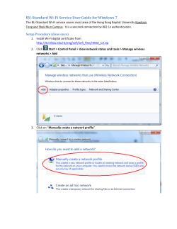

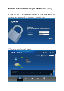


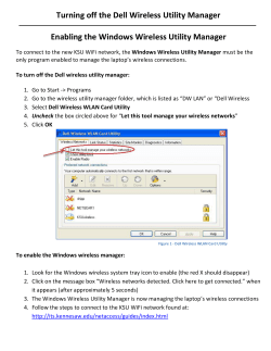

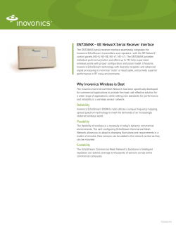
© Copyright 2026