
Document 310457
Pos : 2 /D okumentati on allgemein/Ei nband/Ei nband H andbuch - Dec kbl att ohne Variantenfel d (Standar d) @ 9\mod_1285229289866_0.doc x @ 64941 @ @ 1 Manual WAGO-Software WAGO DALI Configurator for the configuration of the DALI network and the DALI Multi-Master Module 753-647 Version 2.0.0 Pos : 3 /Alle Serien (Allgemeine M odul e)/Hinweise z ur Dokumentation/Impres sum für Standardhandbüc her - allg. Angaben, Ansc hriften, Tel efonnummer n und E-Mail-Adres sen @ 3\mod_1219151118203_21.doc x @ 21060 @ @ 1 2 WAGO-Software WAGO DALI Configurator © 2014 by WAGO Kontakttechnik GmbH & Co. KG All rights reserved. WAGO Kontakttechnik GmbH & Co. KG Hansastraße 27 D-32423 Minden Phone: Fax: +49 (0) 571/8 87 – 0 +49 (0) 571/8 87 – 1 69 E-Mail: [email protected] Web: http://www.wago.com Technical Support Phone: Fax: +49 (0) 571/8 87 – 5 55 +49 (0) 571/8 87 – 85 55 E-Mail: [email protected] Every conceivable measure has been taken to ensure the accuracy and completeness of this documentation. However, as errors can never be fully excluded, we always appreciate any information or suggestions for improving the documentation. E-Mail: [email protected] We wish to point out that the software and hardware terms as well as the trademarks of companies used and/or mentioned in the present manual are generally protected by trademark or patent. === Ende der Liste für T extmar ke Ei nband_vorne === Manual Version 2.0.0 WAGO-Software WAGO DALI Configurator Table of Contents 3 Pos : 5 /D okumentati on allgemein/Verzeic hnisse/Inhalts verz eichnis - Ü berschrift oG und Verzei chnis @ 3\mod_1219151230875_21.doc x @ 21063 @ @ 1 Table of Contents 1 1.1 1.2 1.3 1.4 1.5 Notes about this Documentation ................................................................. 6 Scope ......................................................................................................... 6 Copyright................................................................................................... 6 Symbols ..................................................................................................... 7 Number Notation ....................................................................................... 9 Font Conventions ...................................................................................... 9 2 Important Notes ......................................................................................... 10 2.1 Legal Bases ............................................................................................. 10 2.1.1 Subject to Changes ............................................................................. 10 2.1.2 Personnel Qualification ...................................................................... 10 2.2 Safety Advice (Precautions) .................................................................... 10 2.3 Requirements........................................................................................... 12 2.3.1 PC Hardware ...................................................................................... 12 2.3.2 PC Software ........................................................................................ 12 2.3.3 WAGO-I/O-SYSTEM ........................................................................ 13 2.3.4 Compatibility List Fieldbus Coupler/Controller ................................ 14 3 WAGO DALI Configurator ...................................................................... 15 3.1 Overview of Important Functions ........................................................... 15 3.2 Installation ............................................................................................... 16 3.3 Launching the WAGO DALI Configurator ............................................ 16 3.3.1 Launching from WAGO-I/O-CHECK ............................................... 16 3.3.2 Launching as a Stand-Alone Tool ...................................................... 17 4 User Interface ............................................................................................. 18 4.1 “START” Tab ......................................................................................... 19 4.1.1 Communication Settings .................................................................... 23 4.1.2 Addressing .......................................................................................... 24 4.1.2.1 Control Gears (ECG) ..................................................................... 27 4.1.2.1.1 Start Addressing ........................................................................ 27 4.1.2.1.2 Add ............................................................................................ 27 4.1.2.1.3 Editing ....................................................................................... 28 4.1.2.1.4 Locate ........................................................................................ 30 4.1.2.1.5 Using a Barcode Scanner to Sort ECGs .................................... 30 4.1.2.2 Sensor Types 1 ............................................................................... 31 4.1.2.2.1 Start Addressing ........................................................................ 31 4.1.2.2.2 Add ............................................................................................ 31 4.1.2.2.3 Edit ............................................................................................ 32 4.1.2.2.4 Locate ........................................................................................ 34 4.1.2.3 Sensor Types 2 ............................................................................... 34 4.1.2.3.1 Start Addressing ........................................................................ 34 4.1.2.3.2 Add ............................................................................................ 35 4.1.2.3.3 Editing ....................................................................................... 35 4.1.2.3.4 Locate ........................................................................................ 37 4.1.3 Tree Structure ..................................................................................... 37 4.1.3.1 Selecting/Deselecting Devices....................................................... 37 4.1.3.2 Context Menu ................................................................................ 37 Manual Version 2.0.0 4 Table of Contents WAGO-Software WAGO DALI Configurator 4.1.3.3 Setting Up Building/Room Structure............................................. 38 4.1.3.4 Assigning ECGs to Your “Rooms” ............................................... 39 4.1.4 Groups & Scenes ................................................................................ 40 4.1.4.1 Assigning Groups .......................................................................... 40 4.1.4.2 Group Context Menu ..................................................................... 40 4.1.4.3 Assigning Scenes ........................................................................... 41 4.1.4.4 Scene Context Menu ...................................................................... 42 4.1.5 Configuration...................................................................................... 43 4.1.5.1 “Control Gear (Common)” Tab ..................................................... 44 4.1.5.2 “Emergency Lighting (DT1)” Tab ................................................. 45 4.1.5.3 “Digital Signal into DC Voltage (DT5)” Tab ................................ 46 4.1.5.4 “LED Module (DT6)” Tab ............................................................ 46 4.1.5.5 “Switching Function (DT7)” Tab .................................................. 47 4.1.5.6 “Colour Control (DT8)” Tab ......................................................... 48 4.1.5.7 “Memory Banks” Tab .................................................................... 50 4.1.5.7.1 Multiple Devices ....................................................................... 50 4.1.5.7.2 Single Device ............................................................................ 51 4.1.5.8 “Push Button (DT1)” Tab .............................................................. 52 4.1.5.9 “Presence Detector (DT2)” Tab ..................................................... 52 4.1.5.10 “Light Sensor (DT3)” Tab ............................................................. 52 4.1.5.11 “Presence Detector (DT4)” Tab ..................................................... 53 4.1.5.12 “MSensor (Common)” Tab............................................................ 53 4.1.5.13 “Button (Common)” Tab ............................................................... 54 4.1.5.14 “Push Button (DT50)” Tab ............................................................ 54 4.2 “MODULE SETTINGS” Tab ................................................................. 55 4.2.1 Overview of Configuration Settings ................................................... 56 4.2.1.1 “Easy Mode” .................................................................................. 56 4.2.1.2 “Full Mode” ................................................................................... 57 4.2.1.3 General Settings ............................................................................. 57 4.2.2 Using the “Construction Site Function” ............................................. 58 4.3 “DIAGNOSTICS” Tab ........................................................................... 60 4.3.1 Updating Diagnostic Information ....................................................... 62 4.3.2 Creating a Status Report ..................................................................... 63 4.3.3 Light Operating Hours ........................................................................ 63 4.3.3.1 Reset Operating Hours ................................................................... 63 4.3.3.2 Set Operating Hours ...................................................................... 64 4.4 Status Bar ................................................................................................ 64 4.5 “File” Tab ................................................................................................ 66 4.5.1 Project Documentation: Create “WAGO DALI Configurator Report” ............................................................................................... 68 5 5.1 5.2 5.3 5.4 5.5 5.6 5.7 5.8 5.9 Startup – Example Configuration ............................................................ 70 Establish Connection ............................................................................... 70 Address Control Gears (ECG) ................................................................ 70 Create Room Structure ............................................................................ 70 Assigning Lighting Groups ..................................................................... 71 Assigning a Light Scene.......................................................................... 71 Configuring Control Gears (ECG) .......................................................... 72 Addressing and Assigning Type 2 Sensors ............................................. 72 Configuring Type 2 Sensors.................................................................... 72 Querying the Control Gear Status ........................................................... 72 Manual Version 2.0.0 WAGO-Software WAGO DALI Configurator 5.10 5.11 6 Table of Contents 5 Generating Project Documentation ......................................................... 73 Setting Cyclic Control Gear Query and Saving the Project .................... 73 Glossary ...................................................................................................... 74 List of Figures ...................................................................................................... 77 List of Tables ........................................................................................................ 78 === Ende der Liste für T extmar ke Verzeic hnis_vor ne === Manual Version 2.0.0 6 Notes about this Documentation WAGO-Software WAGO DALI Configurator Pos : 7 /Alle Serien (Allgemeine M odul e)/Übersc hriften für all e Serien/Hi nweis z ur Dokumentation/Hinweis e z ur D okumentation - Ü bersc hrift 1 @ 4\mod_1237987661750_21.doc x @ 29029 @ 1 @ 1 1 Notes about this Documentation Pos : 8 /Alle Serien (Allgemeine M odul e)/Hinweise z ur Dokumentation/Hi nweis e/Hi nweis : D okumentation aufbewahr en @ 4\mod_1237987339812_21.doc x @ 29026 @ @ 1 Keep this documentation! The operating instructions are part of the product and shall be kept for the entire lifetime of the device. They shall be transferred to each subsequent owner or user of the device. Care must also be taken to ensure that any supplement to these instructions are included, if applicable. Pos : 9 /Seri e 759 ( WAGO- Software)/Hi nweis e z ur D okumentati on/Gültigkeits bereic h D ALI-Konfigurator ( 753-0647) @ 12\mod_1331296281515_21.doc x @ 90573 @ 2 @ 1 1.1 Scope This documentation applies for the WAGO DALI Configurator in conjunction with the DALI Multi Master Module 753-647. Pos : 10.1 /All e Seri en ( Allgemei ne Module)/Hi nweis e zur D okumentati on/Urhebersc hutz ausführlich @ 4\mod_1235565145234_21.doc x @ 27691 @ 2 @ 1 1.2 Copyright This Manual, including all figures and illustrations, is copyright-protected. Any further use of this Manual by third parties that violate pertinent copyright provisions is prohibited. Reproduction, translation, electronic and phototechnical filing/archiving (e.g., photocopying) as well as any amendments require the written consent of WAGO Kontakttechnik GmbH & Co. KG, Minden, Germany. Non-observance will involve the right to assert damage claims. Pos : 10.2 /Dokumentation allgemei n/Glieder ungs elemente/---Seitenwechs el--- @ 3\mod_1221108045078_0.doc x @ 21810 @ @ 1 Manual Version 2.0.0 WAGO-Software WAGO DALI Configurator Notes about this Documentation 7 Pos : 10.3 /All e Seri en ( Allgemei ne Module)/Ü bers chriften für alle Serien/Hinweis z ur D okumentati on/Symbole - Ü berschrift 2 @ 13\mod_1351068042408_21.doc x @ 105270 @ 2 @ 1 1.3 Symbols Pos : 10.4.1 /All e Serien ( Allgemei ne Module)/Wic htige Erläuterungen/Sicherheits- und sons tige Hinweis e/Gefahr/Gefahr: _War nung vor Personenschäden allgemei n_ - Erl äuter ung @ 13\mod_1343309450020_21.doc x @ 101029 @ @ 1 Personal Injury! Indicates a high-risk, imminently hazardous situation which, if not avoided, will result in death or serious injury. Pos : 10.4.2 /All e Serien ( Allgemei ne Module)/Wic htige Erläuterungen/Sicherheits- und sons tige Hinweis e/Gefahr/Gefahr: _War nung vor Personenschäden durc h elektrisc hen Strom_ - Erläuterung @ 13\mod_1343309694914_21.doc x @ 101030 @ @ 1 Personal Injury Caused by Electric Current! Indicates a high-risk, imminently hazardous situation which, if not avoided, will result in death or serious injury. Pos : 10.4.3 /All e Serien ( Allgemei ne Module)/Wic htige Erläuterungen/Sicherheits- und sons tige Hinweis e/Warnung/Warnung: _Warnung vor Personensc häden allgemei n_ - Erläuterung @ 13\mod_1343309877041_21.doc x @ 101035 @ @ 1 Personal Injury! Indicates a moderate-risk, potentially hazardous situation which, if not avoided, could result in death or serious injury. Pos : 10.4.4 /All e Serien ( Allgemei ne Module)/Wic htige Erläuterungen/Sicherheits- und sons tige Hinweis e/Vorsic ht/Vorsicht: _War nung vor Pers onensc häden allgemein_ - Erläuterung @ 13\mod_1343310028762_21.doc x @ 101038 @ @ 1 Personal Injury! Indicates a low-risk, potentially hazardous situation which, if not avoided, may result in minor or moderate injury. Pos : 10.4.5 /All e Serien ( Allgemei ne Module)/Wic htige Erläuterungen/Sicherheits- und sons tige Hinweis e/Achtung/Achtung: _War nung vor Sac hsc häden allgemein_ - Erläuterung @ 13\mod_1343310134623_21.doc x @ 101041 @ @ 1 Damage to Property! Indicates a potentially hazardous situation which, if not avoided, may result in damage to property. Pos : 10.4.6 /All e Serien ( Allgemei ne Module)/Wic htige Erläuterungen/Sicherheits- und sons tige Hinweis e/Achtung/Achtung: _War nung vor Sac hsc häden durc h elektr ostatis che Aufladung_ - Erläuterung @ 13\mod_1343310227702_21.doc x @ 101044 @ @ 1 Damage to Property Caused by Electrostatic Discharge (ESD)! Indicates a potentially hazardous situation which, if not avoided, may result in damage to property. Pos : 10.4.7 /All e Serien ( Allgemei ne Module)/Wic htige Erläuterungen/Sicherheits- und sons tige Hinweis e/Hi nweis /Hinweis: _Wic htiger Hi nweis allgemein_ - Erläuterung @ 13\mod_1343310326906_21.doc x @ 101047 @ @ 1 Important Note! Indicates a potential malfunction which, if not avoided, however, will not result in damage to property. Pos : 10.4.8 /All e Serien ( Allgemei ne Module)/Wic htige Erläuterungen/Sicherheits- und sons tige Hinweis e/Infor mation/Infor mation: _Weiter e Infor mation allgemei n_ - Erl äuter ung @ 13\mod_1343310439814_21.doc x @ 101051 @ @ 1 Manual Version 2.0.0 8 Notes about this Documentation WAGO-Software WAGO DALI Configurator Additional Information: Refers to additional information which is not an integral part of this documentation (e.g., the Internet). Pos : 10.5 /Dokumentation allgemei n/Glieder ungs elemente/---Seitenwechs el--- @ 3\mod_1221108045078_0.doc x @ 21810 @ @ 1 Manual Version 2.0.0 WAGO-Software WAGO DALI Configurator Notes about this Documentation 9 Pos : 10.6 /All e Seri en ( Allgemei ne Module)/Hi nweis e zur D okumentati on/Zahlens ysteme @ 3\mod_1221059454015_21.doc x @ 21711 @ 2 @ 1 1.4 Number Notation Table 1: Number notation Number code Decimal Hexadecimal Binary Example 100 0x64 '100' '0110.0100' Note Normal notation C notation In quotation marks, nibble separated with dots (.) Pos : 10.7 /All e Seri en ( Allgemei ne Module)/Hi nweis e zur D okumentati on/Sc hriftkonventi onen @ 3\mod_1221059521437_21.doc x @ 21714 @ 2 @ 1 1.5 Font Conventions Table 2: Font conventions Font type italic Menu > Input “Value” [Button] [Key] Pos : 11 /D okumentation allgemei n/Glieder ungs elemente/---Seitenwechs el--- @ 3\mod_1221108045078_0.doc x @ 21810 @ @ 1 Manual Version 2.0.0 Indicates Names of paths and data files are marked in italic-type. e.g.: C:\Programme\WAGO-I/O-CHECK Menu items are marked in bold letters. e.g.: Save A greater-than sign between two names means the selection of a menu item from a menu. e.g.: File > New Designation of input or optional fields are marked in bold letters, e.g.: Start of measurement range Input or selective values are marked in inverted commas. e.g.: Enter the value “4 mA” under Start of measurement range. Pushbuttons in dialog boxes are marked with bold letters in square brackets. e.g.: [Input] Keys are marked with bold letters in square brackets. e.g.: [F5] 10 Important Notes WAGO-Software WAGO DALI Configurator Pos : 12.1 /All e Seri en ( Allgemei ne Module)/Ü bers chriften für alle Serien/Wichtige Erläuter ungen/Wichtige Erläuter ung en - Übersc hrift 1 @ 4\mod_1241428899156_21.doc x @ 32170 @ 1 @ 1 2 Important Notes Pos : 12.2 /Serie 759 (WAGO-Softwar e)/Hinweis e z ur Dokumentation/Wic htige Erläuterungen/Wic htige Erläuterungen - Einl eitung Software @ 12\mod_1333628906785_21.doc x @ 93367 @ @ 1 This section describes the legal principles and system requirements for using the software in compliance with intended purpose, underlying provisions and stated specifications. Pos : 12.3 /All e Seri en ( Allgemei ne Module)/Ü bers chriften für alle Serien/Wichtige Erläuter ungen/Rechtliche Gr undl agen - Ü bersc hrift 2 @ 3\mod_1221060626343_21.doc x @ 21726 @ 2 @ 1 2.1 Legal Bases Pos : 12.4 /All e Seri en ( Allgemei ne Module)/Wic htige Erläuterungen/Änderungs vor behalt - Ü bers chrift 3 und Inhalt @ 3\mod_1221060036484_21.doc x @ 21720 @ 3 @ 1 2.1.1 Subject to Changes WAGO Kontakttechnik GmbH & Co. KG reserves the right to provide for any alterations or modifications that serve to increase the efficiency of technical progress. WAGO Kontakttechnik GmbH & Co. KG owns all rights arising from the granting of patents or from the legal protection of utility patents. Third-party products are always mentioned without any reference to patent rights. Thus, the existence of such rights cannot be excluded. Pos : 12.5 /Serie 759 (WAGO-Softwar e)/Hinweis e z ur Dokumentation/Wic htige Erläuterungen/Pers onalqualifi kation Software @ 12\mod_1331792915159_21.doc x @ 91000 @ 3 @ 1 2.1.2 Personnel Qualification Any steps related to the use of WAGO software may only be performed by qualified employees with sufficient knowledge of handling the respective PC system used. Steps in which files are created or changed on the PC system may only be performed by qualified employees with sufficient knowledge in the administration of the PC system used in addition to the aforementioned. Steps in which the behavior of the PC system in a network is changed may only be performed by qualified employees with sufficient knowledge in the administration of the network used in addition to the aforementioned. Pos : 12.6 /All e Seri en ( Allgemei ne Module)/Ü bers chriften für alle Serien/Wichtige Erläuter ungen/Sic herheits hinweise - Übersc hrift 2 @ 6\mod_1260180299987_21.doc x @ 46724 @ 2 @ 1 2.2 Safety Advice (Precautions) Pos : 12.7 /Serie 759 (WAGO-Softwar e)/Hinweis e z ur Dokumentation/Hi nweis e/Hi nweis : Aktuell e Sicherheitss oftwar e ver wenden! + Nicht benötigte Software deakti vi eren oder de.! @ 12\mod_1333429179862_21.doc x @ 92870 @ @ 1 Use up-to-date security software! Secure operation of the PC system can be at risk as a result of malware such a viruses and Trojans, as well as related threats such as denial-of-service attacks. Therefore, make sure that the latest security software and definitions are always installed on the PC system. Manual Version 2.0.0 WAGO-Software WAGO DALI Configurator Important Notes 11 Disable or uninstall software that is no longer required! The vulnerability of a PC system against malware and related threats increases with the number of installed or active software components (applications and services). Therefore, uninstall or disable software components that are not needed for the purpose at hand. Pos : 13 /D okumentation allgemei n/Glieder ungs elemente/---Seitenwechs el--- @ 3\mod_1221108045078_0.doc x @ 21810 @ @ 1 Manual Version 2.0.0 12 Important Notes WAGO-Software WAGO DALI Configurator Pos : 14 /All e Seri en (Allgemei ne Module)/Ü berschriften für alle Serien/Wichtige Erläuterungen/Vorauss etzungen - Ü bersc hrift 2 @ 12\mod_1339753596379_21.doc x @ 97770 @ 2 @ 1 2.3 Requirements Pos : 15.1 /All e Seri en ( Allgemei ne Module)/Ü bers chriften für alle Serien/Wichtige Erläuter ungen/PC-H ardware - Übersc hrift 3 @ 12\mod_1339753695836_21.doc x @ 97773 @ 3 @ 1 2.3.1 PC Hardware Pos : 15.2 /Serie 759 (WAGO-Softwar e)/WAGO-DALI- Konfigur ator/T abelle: Vor auss etzungen PC-Hardwar e (753-0647) @ 12\mod_1340040864589_21.doc x @ 98028 @ @ 1 Table 3: Requirements PC Hardware Component Operating system Random access memory (RAM) Free hard disk storage unit Processor Other Requirements Windows XP (SP3)/Windows 7/ Windows 8 Min. 512 MB Min. 20 MB for the WAGO DALI Configurator and 610 MB for the .NET 4.0 Framework Min. 1 GHz Installed network card, .NET 4.0 Framework (Redistributables are provided), standard web browser with Java support Pos : 15.3 /All e Seri en ( Allgemei ne Module)/Ü bers chriften für alle Serien/Wichtige Erläuter ungen/PC- Software - Ü berschrift 3 @ 12\mod_1339753791838_21.doc x @ 97776 @ 3 @ 1 2.3.2 PC Software Pos : 15.4 /Serie 759 (WAGO-Softwar e)/WAGO-DALI- Konfigur ator/T abelle: Er for derlic he PC-Softwar e (753-0647) @ 12\mod_1340040493236_21.doc x @ 98019 @ @ 1 Table 4: Required PC Software Component WAGO-I/O-PRO .NET Framework 4.0 WAGO DALI Configurator from Version 2.0 Reference source (order number) WAGO (759-333) Microsoft (free download under: www.microsoft.com) WAGO Stand Alone Tool, download under: www.wago.com Pos : 15.5 /Serie 759 (WAGO-Softwar e)/WAGO-DALI- Konfigur ator/T abelle: Opti onal e PC- Software ( 753- 0647) @ 12\mod_1340040591285_21.doc x @ 98022 @ @ 1 Table 5: Optional PC Software Component WAGO-I/O-CHECK WAGO Ethernet Settings Reference source (order number) WAGO (759-302) WAGO (free download at: www.wago.com) Pos : 15.6 /Dokumentation allgemei n/Glieder ungs elemente/---Seitenwechs el--- @ 3\mod_1221108045078_0.doc x @ 21810 @ @ 1 Manual Version 2.0.0 WAGO-Software WAGO DALI Configurator Important Notes 13 Pos : 15.7 /All e Seri en ( Allgemei ne Module)/Ü bers chriften für alle Serien/Wichtige Erläuter ungen/WAGO-I/O-SYSTEM - Übersc hrift 3 @ 13\mod_1342779422584_21.doc x @ 100660 @ 3 @ 1 2.3.3 WAGO-I/O-SYSTEM Pos : 15.8 /Serie 759 (WAGO-Softwar e)/WAGO-DALI- Konfigur ator/T abelle: Er for derlic he Komponenten des WAGO-I/O-SYST EMs ( 753-0647) @ 12\mod_1340040395421_21.doc x @ 98016 @ @ 1 Table 6: Required Hardware of the WAGO-I/O-SYSTEM Component Fieldbus controller/PLC WAGO-I/O-SYSTEM 750 e. g. ETHERNET PLC 750-881 DALI Multi-Master Module 753-647 End Module 750-600 Current supply for the indirect supply of the DALI Bus participants via the DALI Multi-Master Module 753-647, e. g.: DC/DC Converter 753-620 or Current supply 787-1007 Reference source (order number) WAGO (750-881) WAGO (753-647) WAGO (750-600) WAGO (753-620) WAGO (787-1007) Destruction of DALI subscribers due to misuse of the WAGO power supply 787-1007! Please note that the power supply by WAGO (Item No.: 787-1007) may only be connected to the DALI Multi-Master Module 753-647. The power supply for the DALI bus is provided indirectly via the DALI Multi-Master Module. A direction connect to the DALI bus can result in the destruction of the attached DALI slaves. Therefore, never connect the WAGO Power Supply 787-1007 to a DALI network directly without a DALI Multi-Master Module 753-647 connected between the power supply and the network. Manual Version 2.0.0 14 Important Notes 2.3.4 WAGO-Software WAGO DALI Configurator Compatibility List Fieldbus Coupler/Controller Table 7: Compatibility list, status: June 2014 Fieldbus coupler/controller 750-88x 750-831 750-830 750-829 750-849 750-820x 750-833 750-333 750-343 750-370 750-375 750-377 1) 2) Pos : 16 /D okumentation allgemei n/Glieder ungs elemente/---Seitenwechs el--- @ 3\mod_1221108045078_0.doc x @ 21810 @ @ 1 From FW version 1) 05 03 04 05 05 02 16 17 No support 06 All All Note Checkbox Allow Controlmode over Ethernet must be activated! 2) It is generally recommended to use the latest FW version available. WBM page “Features” > “Wago communication over Ethernet” Manual Version 2.0.0 WAGO-Software WAGO DALI Configurator WAGO DALI Configurator 15 Pos : 17 /Serie 759 ( WAGO-Softwar e)/WAGO-D ALI- Konfig urator/WAGO-D ALI-Konfigurator 2014 @ 18\mod_1392112254603_21.doc x @ 144960 @ 12223312334555554555545555344443444434444444554444444234443233344223 @ 1 3 WAGO DALI Configurator Download the WAGO DALI Configurator You can download the WAGO DALI Configurator as a stand-alone tool from the WAGO website at: http://www.wago.com. The WAGO DALI Configurator allows easy commissioning of a DALI network via DALI Multi-Master Module 753-647. The WAGO DALI Configurator not only provides functions for easy startup and configuration, but also for the service, care and maintenance of a DALI network. That includes the offline configuration of the entire DALI network including the ECGs and sensors and saving and repeating device configurations, so that a replaced device can be reconstructed with database values. You can copy the device settings to another device or to several duplicates. If you are replacing an ECG, but keeping the lighting, you can write the hours of operation of the lighting to the DALI Multi-Master Module. The network overview appears in a tree structure. All online DALI Multi-Master Modules are displayed in the Module navigation. The tree structure shows the DALI network of the DALI Multi-Master Module currently selected. Multiple selection of devices ensures an efficient configuration. Logging operating hours with firmware version 04 or later! The “Logging of operating hours” function is integrated in firmware version 04 and later. This function is disabled for DALI Multi-Master Modules with older firmware versions. 3.1 Overview of Important Functions • • • • • • • • • • • Manual Version 2.0.0 Addressing of the DALI bus subscribers Scenes and group formation Control gear configuration (ECG) Sensor configuration I/O module-specific settings Diagnostic function Import and export function Status messages from defective ECGs/lamps Manually connect/disconnect Signaling a communication interruption Displaying, resetting and logging*) operating hours *) for DALI Multi-Master Modules firmware version 04 or higher 16 WAGO DALI Configurator 3.2 WAGO-Software WAGO DALI Configurator Installation The WAGO DALI Configurator can be installed as part of the WAGO-I/OCHECK software (Item No.: 759-302) version 3.5.1.1 or higher to launch it directly from WAGO I/O-CHECK. The WAGO DALI Configurator is also easy to install as a stand-alone tool from a “Setup.exe” file with user-guided wizards. 3.3 Launching the WAGO DALI Configurator WAGO-I/O-CHECK If available, you can launch the WAGO DALI Configurator from the WAGO-I/OCHECK startup tool (version 3.5.1.1 or higher)! The WAGO-I/O-CHECK startup software is available under Item No. 759-302 on a CD-ROM. The requirements for online configuration described in the following sections include: • The hardware configuration of your fieldbus node is correct. • The DALI networks is installed without errors and is wired. • The WAGO DALI Configurator software (as a stand-alone tool or as part of the WAGO-I/O-CHECK software) is available on your PC. 3.3.1 Launching from WAGO-I/O-CHECK To launch the software from WAGO-I/O-CHECK directly, the program must also be available on the PC. 1. Read the hardware configuration of your fieldbus node from the WAGOI/O-CHECK startup tool. 2. Right-click the icon for the DALI Multi-Master Module. 3. In the context menu, select the Settings menu item (see the figure below). The WAGO DALI Configurator opens. Manual Version 2.0.0 WAGO-Software WAGO DALI Configurator WAGO DALI Configurator 17 Figure 1: Launching the WAGO DALI Configurators from WAGO-I/O-CHECK 3.3.2 Launching as a Stand-Alone Tool 1. Launch the WAGO DALI Configurator by double-clicking the .exe file. The WAGO DALI Configurator opens. The “START” tab is open by default. Figure 2: Launching the WAGO DALI Configurator by clicking the .exe file The user interface, its functions and views are described in the next sections. Manual Version 2.0.0 18 4 User Interface WAGO-Software WAGO DALI Configurator User Interface The user interface is divided into seven areas: Figure 3: User interface Table 8: Legend for the “User interface” figure Pos. 1 2 3 4 5 6 7 Explanation Toolbar for quick access Tabs Ribbon with contextual buttons, selection boxes and checkboxes Contextual configuration area Status bar Module navigation: Selection of the current DALI Multi-Master Modules Tree structure There are four tabs. There are some views of the user interface on the tabs. • • • • FILE START MODULE SETTINGS DIAGNOSTICS Each tab has its own ribbon with buttons, selection boxes and/or checkboxes that are described in more detail in the following sections. Manual Version 2.0.0 WAGO-Software WAGO DALI Configurator 4.1 User Interface 19 “START” Tab Figure 4: View of the “START” tab On the “START” tab, the ribbon is horizontal below the tab. The buttons, selection boxes and checkboxes on the ribbon are depend on context in part. Table 9: Buttons of the “START” tab – Connection Button Label [Connect] [Disconnect] [Settings] Description Connection (only visible if not connected) Establishes the connection to the DALI Multi-Master Module. (only visible if connected) Disables the connection to the DALI MultiMaster Module. Click this button to open the “Communication Settings” dialog, see section “Communication Settings”. You can work with three main views: • Addressing • Groups & Scenes • Configuration Click the respective buttons on the ribbon to switch between views. Manual Version 2.0.0 20 User Interface WAGO-Software WAGO DALI Configurator Table 10: Buttons of the “START” tab – View Button Label [Addressing] [Groups & Scenes] [Configuration] Description View Click this button to switch to the view for addressing, see section “Addressing”. Click this button to switch to the view for assigning the devices in groups and scenes, see section “Groups & Scenes”. Click this button to switch to the view for configuring the devices, see section “Configuration”. Table 11: Buttons of the “START” tab – DALI Network Button Label [Central On] [Central Off] [Locate Start] [Locate Stop] / * Switch On Description DALI Network Click this button to switch ON all lights connected to the DALI line. Click this button to switch OFF all lights connected to the DALI line. Click this button to start the localization function for one or more selected DALI control gears for identifying and if necessary, checking the physical installation location. Click this button to stop the localization function. A steady light is used for the localization function of ECGs. A flashing light is used for the localization function of ECGs. Manual Version 2.0.0 WAGO-Software WAGO DALI Configurator User Interface 21 Table 11: Buttons of the “START” tab – DALI Network Button Label [Read All] [Compare] [Write All] * Description Click this button to read addresses, group and scene information and configuration parameters of all connected DALI network devices. Click this button to compare a configuration (offline) with another configuration available in the DALI network (online). Click this button to write all data to the DALI network devices available online. Default Table 12: Buttons of the “START” tab– Actions Button Label [Read] [Write] Manual Version 2.0.0 Description Actions Contextual: • In the Addressing view: Addressed devices are searched (depending on the selected tab) • In the Groups & Scenes view: Group and scene settings are read. • In the Configuration view: The device parameters selected in the topology tree are read (depending on the selected tab) Contextual: • In the Addressing view: Disabled • In the Groups & Scenes view: Group and scene settings are written • In the Configuration view: The device parameters of the selected device(s) are written 22 User Interface WAGO-Software WAGO DALI Configurator Table 13: Buttons of the “START” tab – Addressing Button Label [Start] * / Only Unaddressed Devices * / Reset Values / * Identify * Description Addressing Choose between: • “Random addressing” (The DALI network device should be assigned a random address.) • “Physical addressing” (The DALI network device is identified and subsequently addressed, e.g., by the push of a button or by unscrewing and-again screwing in the lighting.) Click this button to launch the addressing operation for the tab currently selected (control gears, sensor type 1 or sensor type 2). Only devices without a short address will be addressed.* All devices are readdressed. The devices are reset to their reset values.* The devices are not reset to their reset values.* Each readdressed device is identified by the address assignment. No identification is made while addressing.* Default Manual Version 2.0.0 WAGO-Software WAGO DALI Configurator 4.1.1 User Interface 23 Communication Settings To set the communication parameters for the link between the DALI Configurator and WAGO fieldbus controller, click the [Settings] button on the ribbon. The “Communication Settings” dialog appears Figure 5: “Communication Settings” dialog In this dialog, you can choose the connection type in the Connection selection box: • ETHERNET • Serial connection In the Settings area, you can do the following based on the selection made: • Enter an IP address in the IP Address input field. • Select the associated COM port in the Port selection box. Select or enter the required number in the DALI Module position selection box. Click the [OK] button to confirm your entries. Manual Version 2.0.0 24 User Interface 4.1.2 WAGO-Software WAGO DALI Configurator Addressing To set the tree structure for the network topology, to add DALI network devices, to assign device labels and to address all DALI network devices, click the [Addressing] button. Figure 6: “Addressing”, “Control Gears” view (example) Im Konfigurationsbereich stehen Ihnen nun 3 weitere Registerkarten zur Verfügung, unter denen Sie Ihrem Netzwerk verschiedene DALINetzwerkteilnehmer hinzuzufügen können: Figure 7: Tabs in the “Addressing” view • • • Control Gears (ECGs) Sensor Type 1 (pushbutton couplers and multi-sensors) Sensor Type 2 (pushbutton couplers and multi-sensors) Distinction between sensor types 1 and 2 The distinction of sensor types is new in this version of the WAGO DALI Configurator. Sensor Type 1 includes: • WAGO DALI Multi-Sensor Kit • WAGO DALI Sensor Coupler • Sensor Adapter OSRAM DALI PROFESSIONAL, 2851-8201 2851-8202 Manual Version 2.0.0 WAGO-Software WAGO DALI Configurator • • • User Interface 25 combinable with: - Sensor OSRAM DALI HIGHBAY - Sensor OSRAM DALI VISION Pushbutton coupler OSRAM DALI PRO PB Coupler Light installation sensor OSRAM DALI LS/PD LI Radar sensor OSRAM DALI Professional Sensor Coupler HF LS LI Sensor Type 2 includes: • WAGO DALI MSensor-02 5DPI 41rc (ceiling installation) 2851-8301 • WAGO DALI MSensor-02 5DPI 41w (socket installation) 2851-8302 • WAGO DALI MSensor-02 5DPI 41rs (surface mount) 2851-8303 • Pushbutton coupler TRIDONIC DALI XC The following table provides an overview of the network devices that can be added: Manual Version 2.0.0 26 User Interface WAGO-Software WAGO DALI Configurator Table 14: List of available DALI network devices Icon Function Control Gear (ECG) Icon/type 0 Label Standard ECG 1 Separate emergency lighting 2 Discharge lamp 3 Low voltage halogen lamp 4 Filament lamp 5 6 Converting the digital signal into a DC voltage LED lamp 7 Switching function 8 Color control device 9 Sequencer 250 [List of all recognized gear types] Sensor type 1: Light sensor Sensor type 1: Presence detector Sensor type 1: Push button Sensor type 1: Error message Sensor type 2: Light sensor Sensor type 2: Presence detector Sensor type 2: Remote control Sensor type 2: Button 255 Error message: Duplicate address or undefined response.* Several gear types are supported. MSensor – Brightness sensor function MSensor – Presence detection function Push button [+ Gear type] Error message: Duplicate address or undefined response.* MSensor – Brightness sensor function MSensor – Presence detection function MSensor – Remote control Button Manual Version 2.0.0 WAGO-Software WAGO DALI Configurator User Interface 27 Table 14: List of available DALI network devices Icon * 4.1.2.1 Function Sensor type 2: Error message Icon/type Label [+ Gear type] Error message: Duplicate address or undefined response.* Procedure for resolving duplicate addresses: See section “DIAGNOSTICS Tab”. Control Gears (ECG) 4.1.2.1.1 Start Addressing Addressing involves current tab! Addressing is always only carried out for the devices of the tab currently selected (Control Gears, Sensor Type 1, Sensor Type 2) and not for all gear types at the same time. 1. To start addressing, first establish the connection to the DALI Multi-Master Module by clicking the [Connect] button. 2. In the selection box, choose between the “Random addressing” and “Physical addressing” entries. 3. Click the [Start] button. 4. Click [Yes] to confirm the dialog. The detected ECGs are listed under the “Control Gears” tab. The tree structure can be expanded on the left side of the configuration area. It also contains a list of detected ECGs. 4.1.2.1.2 Add In the case of an offline configuration, the required ECGs can also be created manually from the context menu: 1. To assign an ECG to a DALI Multi-Master Module, first select the “Control Gears” tab. 2. Right-click in the configuration area under the “Control Gears” tab to display the context menu. 3. In the context menu, select Add Control Gear. A dialog appears: Manual Version 2.0.0 28 User Interface WAGO-Software WAGO DALI Configurator Figure 8: “Add Devices” dialog 4. Enter the required number of ECGs in the selection box and click the [Add] button to confirm your entry. The ECGs created are now listed in the table under the “Control Gears” tab. The table contains the following information: • Name • Path • Address • (Type symbol) • Type • Serial Number The tree structure can be expanded in the topology tree on the left side of the configuration area. 5. Double-click in the respective table cell to edit the “Name”, “Address” and “Serial Number” entries. Figure 9: Editing table cells 4.1.2.1.3 Editing Context menu To edit the entries of the individual ECGs, right-click the required row. A context menu appears. Manual Version 2.0.0 WAGO-Software WAGO DALI Configurator User Interface 29 Multiple selections are possible! To edit several ECGs at the same time, click the required entries while holding down the [Shift] key. Click and hold down the [Ctrl] key to select and deselect specific entries. Table 15: Context menu for the “Control Gears” list Menu item Delete Device(s) Delete Device(s) and Address(es) Show Device in Tree Reset Device(s) to Default Values Add Control Gear Swap Name Description Use this menu item to delete the selected ECG(s) from the list. Use this menu item to delete the selected ECG(s) from the list. In addition, the short address is also cleared in the respective ECG. Use this menu item to highlight the selected device in the tree structure. Use this menu item to reset the device parameters to the default values. Groups and scenes are also reset. Use this menu item to open the dialog for adding ECGs. Use the spinner to select the required number and click [Add] to confirm the selection. Use this menu item to open another submenu in which the available ECGs are listed. Click the required ECG in the list to swap the name of the selected ECG with the name of the clicked on ECG. Name To change the name of an ECG, double-click in the respective table cell. The area changes into an input field in which you can enter the required name. Press the [Return] button on your keyboard. The subsequent table entry is selected and you can edit the entry. Address To enter an address for an ECG, double-click in the respective table cell. The area changes into an input field in which you can enter the required address. Press the [Return] button on your keyboard. The subsequent table entry is selected and you can edit the entry. Serial Number To enter or change the serial number of an ECG, double-click in the respective cell. The area changes into an input field in which you can enter the serial number. Manual Version 2.0.0 30 User Interface WAGO-Software WAGO DALI Configurator Table sorting Click in the individual columns of the header to sort the table rows in ascending or descending order. A small black arrow marks the column by which the rows are currently sorted. 4.1.2.1.4 Locate To assign an appropriate name to an existing ECG, you have to identify its installation location. 1. First, make sure that all ECGs are switched OFF by clicking the [Central Off] button on the ribbon. 2. Click the [Locate Start] button on the ribbon. 3. Click an ECG in the list to highlight it. The ECG flashes so that you can identify and assign it an appropriate name. Select the type of signaling To use a steady light for signaling instead of a flashing light for the ECG, select the Switch ON checkbox on the ribbon. 4. Rename the ECG. Press the [Return] button on your keyboard to select and rename the subsequent list entry. 5. Go through and name the ECGs individually. 6. When done, click the [Locate Stop] button on the ribbon. 4.1.2.1.5 Using a Barcode Scanner to Sort ECGs If the serial number of the ECG is available as a barcode (e.g., part of a building plan), you can use a barcode scanner to record the individual ECGs and to assign the required table row: 1. Start Random addressing. 2. If the serial number (8-byte length) of the ECG is available, click in the Serial Number column to select the table cell for editing. 3. Scan the serial number of the ECG to which you want to assign the first address. On the bus (and in the table cell), the address is replaced and the table cell below that is highlighted for editing. 4. Scan the required barcodes one after the other. The addresses are now sorted based on the scan order. Manual Version 2.0.0 WAGO-Software WAGO DALI Configurator 4.1.2.2 User Interface 31 Sensor Types 1 4.1.2.2.1 Start Addressing Addressing involves current tab! Addressing is always only carried out for the devices of the tab currently selected (Control Gears, Sensor Type 1, Sensor Type 2) and not for all gear types at the same time. 1. Make sure that the connection to the required DALI Multi-Master Module has been established. 2. In the selection box, choose between the “Random Addressing” and “Physical Selection” entries. 3. Click the [Start] button. 4. Click [Yes] to confirm the dialog. The detected devices are listed under the “Sensor Type 1” tab. The tree structure can be expanded on the left side of the configuration area. It also contains a list of detected devices. 4.1.2.2.2 Add In the case of an offline configuration, the required sensor types can also be created manually from the context menu: 1. To assign a sensory type 1 to a DALI Multi-Master Module, first select the “Sensor Type 1” tab. 2. Right-click in the configuration area under the “Sensor Type 1” tab to display the context menu. A context menu appears. 3. In the context menu, select Add Device> Add Push Button or Add Multi Sensor. The respective dialog appears. 4. Enter the required number of pushbutton couplers or sensor couplers in the selection box and click [Add] to confirm your entry. The required number of sensor types 1 is listed under the “Sensor Type 1” tab in a table. The table contains the following information: • Name • Path • Address (input field “Adr” within the icon) • Serial number Manual Version 2.0.0 32 User Interface WAGO-Software WAGO DALI Configurator The tree structure can be expanded in the topology tree on the left side of the configuration area. It now contains the added sensor types 1. 5. Double-click in the respective table cell to edit the “Name”, “Address” and “Serial number” entries. 4.1.2.2.3 Edit Context menu To edit the entries of the individual buttons/sensors, right-click the required row. A context menu appears. Multiple selections are possible! To edit several devices at the same time, click the required entries while holding down the [Shift] key. Click and hold down the [Ctrl] key to select and deselect specific entries. Manual Version 2.0.0 WAGO-Software WAGO DALI Configurator User Interface 33 Table 16: Context menu for the “Sensor Type 1” list Menu item Delete Device(s) Delete Device(s) and Address(es) Show Device in Tree Reset Device(s) to Default Values Add Device Swap name Description Use this menu item to delete the selected device(s) from the list. Use this menu item to delete the selected device(s) from the list. In addition, the short address is also cleared in the respective device. Use this menu item to highlight the selected device in the tree structure. Use this menu item to reset the device parameters to the default values. Use this menu item to open another submenu: “Add Push Button”: Use this menu item to open the dialog for adding pushbutton couplers. Use the spinner to select the required number and click [Add] to confirm the selection. “Add Multi Sensor”: Use this menu item to open the dialog for adding multi-sensors. Use the spinner to select the required number and click [Add] to confirm the selection. Use this menu item to open another submenu in which the available sensors of the same type are listed. Click the required sensor in this list to replace change its name. Name To change the name of a button/sensor, double-click in the respective table cell. The area changes into an input field in which you can enter the required name. Address/Adr To enter or change an address for a sensor type 1, click in the icon in the input field. Serial Number To enter or change the serial number of a sensor, double-click in the respective cell. The area changes into an input field in which you can enter the serial number. Manual Version 2.0.0 34 User Interface WAGO-Software WAGO DALI Configurator 4.1.2.2.4 Locate To assign an appropriate name to an existing device of sensor type 1, you have to identify its installation location. 1. Click the [Locate Start] button on the ribbon. 2. Click a device in the list to highlight it. The device emits a signal so that you can identify and assign it an appropriate name. 3. Rename the device. Press the [Return] button on your keyboard to select and rename the subsequent list entry. 4. Go through and name the devices individually. 5. When done, click the [Locate Stop] button on the ribbon. Um einem vorhandenen Gerät vom Sensortyp 1 einen passenden Namen zuordnen zu können, müssen Sie es am Einbauort identifizieren. 4.1.2.3 Sensor Types 2 4.1.2.3.1 Start Addressing Addressing involves current tab! Addressing is always only carried out for the devices of the tab currently selected (Control Gears, Sensor Type 1, Sensor Type 2) and not for all gear types at the same time. 1. Make sure that the connection to the required DALI Multi-Master Module has been established. 2. In the selection box, choose between the “Random Addressing” and “Physical Selection” entries. “Physical Selection” option for pushbutton couplers only Physical addressing is only possible for sensor type 2 when no MSensors are connected! 3. Click the [Start] button. 4. Click [Yes] to confirm the dialog. The detected devices are listed under the “Sensor Type 2” tab. The tree structure can be expanded on the left side of the configuration area. It also contains a list of detected devices. Manual Version 2.0.0 WAGO-Software WAGO DALI Configurator User Interface 35 4.1.2.3.2 Add In the case of an offline configuration, the required sensor types can also be created manually from the context menu: 1. To assign a sensory type 2 to a DALI Multi-Master Module, first select the “Sensor Type 2” tab. 2. Right-click in the configuration area under the “Sensor Type 2” tab to display the context menu. A context menu appears. 3. In the context menu, select Add Device > Add Push Button or Add M-Sensor. The respective dialog appears. 4. Enter the required number of pushbutton couplers or multi-sensors in the selection box and click [Add] to confirm your entry. The required number of sensor types 2 is listed under the “Sensor Type 2” tab in a table. The table contains the following information: • Name • Path • Address (input field Adr with sensors within the icon) • Serial Number The tree structure can be expanded in the topology tree on the left side of the configuration area. It now contains the added sensor types 2. 5. Double-click in the respective table cell to edit the “Name”, “Address” and “Serial Number” entries. 4.1.2.3.3 Editing Context menu To edit the entries of the individual pushbutton couplers/multi-sensors, right-click the required row. A context menu appears. Multiple selections are possible! To edit several devices at the same time, click the required entries while holding down the [Shift] key. Click and hold down the [Ctrl] key to select and deselect specific entries. Manual Version 2.0.0 36 User Interface WAGO-Software WAGO DALI Configurator Table 17: Context menu for the "Sensor Type 2" list Menu item Delete Device(s) Delete Device(s) and Address(es) Show Device in Tree Reset Device(s) to Default Values Add Device Swap Name Description Use this menu item to delete the selected device(s) from the list. Use this menu item to delete the selected device(s) from the list. In addition, the short address is also cleared in the respective device. Use this menu item to highlight the selected device in the tree structure. Use this menu item to reset the device parameters to the default values. Use this menu item to open another submenu: “Add Push Button”: Use this menu item to open the dialog for adding pushbutton couplers. Use the spinner to select the required number and click [Add] to confirm the selection. “Add M-Sensor”: Use this menu item to open the dialog for adding multi-sensors. Use the spinner to select the required number and click [Add] to confirm the selection. Use this menu item to open another submenu in which the available sensors of the same type are listed. Click the required sensor in this list to replace change its name. Name To change the name of a button/sensor, double-click in the respective table cell. The area changes into an input field in which you can enter the required name. Address/Adr To enter or change an address for a sensor type 2, double-click in the respective table cell or click in the icon in the input field. Serial Number To enter or change the serial number of a sensor, double-click in the respective cell. The area changes into an input field in which you can enter the serial number. Manual Version 2.0.0 WAGO-Software WAGO DALI Configurator User Interface 37 4.1.2.3.4 Locate To assign an appropriate name to an existing device of sensor type 2, you have to identify its installation location. 4.1.3 1. Click the [Locate Start] button on the ribbon. 2. Click a device in the list to highlight it. The device emits a signal so that you can identify and assign it an appropriate name. 3. Rename the device. Press the [Return] button on your keyboard to select and rename the subsequent list entry. 4. Go through and name the devices individually. 5. When done, click the [Locate Stop] button on the ribbon. Tree Structure The ECGs and sensors are listed in a tree structure on the left side of the configuration area. The individual levels and sublevels can be expanded and collapsed using the adjacent arrow. 4.1.3.1 4.1.3.2 Selecting/Deselecting Devices • Select device: To select a single device, click the device to highlight it. • Select multiple devices: To select multiple devices, hold down the [Ctrl] key and click all required devices. Alternatively, you can also select successive devices by holding down the [Shift] key and clicking the first and last device. • Deselect device: To deselect a specific device, hold down the [Ctrl] key and click the respective device. The selection is removed. Context Menu Right-click a level in the tree structure or a device in the sublevel to display the context menu for the respective selection. The following menu items are available: Manual Version 2.0.0 38 User Interface WAGO-Software WAGO DALI Configurator Table 18: Context menu for the entries in the tree structure Menu item Add New Section Rename Reset Device(s) to Default Values Delete Restore Device Copy Settings • Groups • Scenes • General Gear Settings • Device Type Specific • All Paste Expand All Collapse All 4.1.3.3 Description Use this menu item to create a new area to which you can add devices by drag & drop. Use this menu item to change the respective node into an input field in which you can enter the required name. Use this menu item to reset the device parameters to the default values. For ECGs, groups and scenes are also reset. This menu item is only enabled for areas. Use this menu item to remove the selected area from the tree structure. Use this menu item to transfer he configuration settings of a specific device to a new replacement device if it has the same address as the previous one. Use these menu items to copy the respective settings of the device currently selected to the cache to then transfer the settings to another device. Use this menu item to transfer saved settings from the cache (see menu item “Copy Settings”) to the device currently selected. Use this menu item to expand the tree structure completely. Use this menu item to collapse the tree structure completely. Setting Up Building/Room Structure To assign the ECGs and sensor types in a clear manner, you can create and name areas and subareas in the tree structure as required. 1. Right-click the tree structure. 2. Select the Add New Section submenu item. 3. Click the new tree level and select the Rename menu item in the context menu. The selected area changes into an input field. Manual Version 2.0.0 WAGO-Software WAGO DALI Configurator User Interface 39 4. Enter an intuitive name for the tree level, e.g., 1st Floor. Info: To create a sublevel (e.g., “Room 1”) for the “1st Floor” tree level, the “1st Floor” level must be selected. In contrast, to create another level of the same type (e.g., “2nd Floor”), the higher-level level must be selected. 5. Repeat these steps until you have created the required building/room structure. Edit level structure You can drag & drop to move areas at any time to edit or correct the room structure later! Figure 10: Setting up the tree structure 4.1.3.4 Assigning ECGs to Your “Rooms” You can drag & drop ECGs/sensors to the required tree levels. In the “Setting up the tree structure” figure, these tree levels have been named as floors or rooms. Manual Version 2.0.0 40 User Interface 4.1.4 WAGO-Software WAGO DALI Configurator Groups & Scenes To assign your DALI control gears groups and scenes and to set dimming values, colors or color temperatures, lick the [Groups & Scenes] button. In the configuration area, there are 2 trees for “Groups” and “Scenes”. You can drag & drop devices from the tree structure to the group tree and scene tree to assign them. Figure 11: View of the “Groups & Scenes, Set Scene Value” configuration area (example) 4.1.4.1 Assigning Groups If you have dragged a device to a group in the group tree, an arrow appears on the left next to the respective group tree entry. You can click on the arrow to expand the devices assigned to the respective group. 4.1.4.2 Group Context Menu Right-click a group to display the context menu: Manual Version 2.0.0 WAGO-Software WAGO DALI Configurator User Interface 41 Table 19: “Groups” context menu Menu item Rename Remove Device(s) from Group 4.1.4.3 Description Select this menu item to change the selected group into an input field in which you can enter the required name. To exit the input field, confirm your entry by pressing the [Return] key on your keyboard or by clicking another group tree structure. Use this menu item to remove attached devices from the group. Assigning Scenes If you drag a device or group of devices to a scene in the scene tree, the “Set Values” dialog appears. Figure 12: “Set Values” dialog (example 1) Specify the level settings in this dialog. 1. Select a value from the spinner or enter a value. 2. Select the Send when changed checkbox. 3. Confirm your entries by clicking [OK]. The dialog closes and an arrow appears on the left next to the respective scene tree entry. You can click on the arrow to expand the devices assigned to the respective scene. The specified dimming value of a device follows in brackets. With some devices (type 8 control gears), you can also specify the color value and color temperature: Manual Version 2.0.0 42 User Interface WAGO-Software WAGO DALI Configurator Figure 13: “Set Values” dialog (example 2) 4.1.4.4 Scene Context Menu Right-click a scene or attached devices to display the related context menu: Table 20: “Scene” context menu Menu item Rename Configure Scene Remove Device(s) from Scene Recall Scene Description Select this menu item to change the selected scene into an input field in which you can enter the required name (e.g., “Room 1”). To exit the input field, confirm your entry by pressing the [Return] key on your keyboard or by clicking another scene tree structure. Use this menu item to open the “Set Values” dialog. (See also section “Assigning Scenes”.) Use this menu item to remove attached devices from the scene. Only enabled if a connection is established and exactly 1 scene is selected. Use this menu item to call up the selected scene (broadcast). Manual Version 2.0.0 WAGO-Software WAGO DALI Configurator 4.1.5 User Interface 43 Configuration To read or write the configuration parameters from DALI network devices, click the [Configuration] button. Additional tabs are available to you in the configuration area. The tabs displayed depend on which gear types are in the selection of the topology tree (tree structure). If the top level (default name “New Line”) of the tree structure is selected, corresponding tabs are created for each underlying gear type. Figure 14: “Configuration” view (example) Manual Version 2.0.0 44 User Interface 4.1.5.1 WAGO-Software WAGO DALI Configurator “Control Gear (Common)” Tab You have access to the following parameters in the table under the “Control Gear (Common)” tab: Table 21: “Control Gear (Common)” tab Name Physical Min level Description Minimum physical lamp output Version Number Power on level Version number Lamp output with voltage recovery System failure level Lamp output in the event of system malfunction (e.g., interrupted DALI line) Min level Minimum lamp output Max level Maximum lamp output Fade time Fade time (time for the dimming value change) Fade speed Fade rate Unit Percent [%] Percent [%] Percent [%] Percent [%] Percent [%] Read/Write R R R/W R/W R/W R/W R/W R/W Manual Version 2.0.0 WAGO-Software WAGO DALI Configurator 4.1.5.2 User Interface 45 “Emergency Lighting (DT1)” Tab You have access to the following parameters in the table under the “Emergency Lighting (DT1)” tab: Table 22: “Emergency Lighting (DT1)” tab Name Emergency Min Level Emergency Max Level Rated Duration Features Extended Version Number Emergency Level Function test delay time Function test interval Manual Version 2.0.0 Description Minimum lamp output for emergency lighting: Minimum brightness level to operate the light in emergency mode. The value can lie between “1” and “Emergency Max Level”. Maximum lamp output for emergency lighting: Maximum brightness level to operate the light in emergency mode. The value can lie between “Emergency Min Level” and “254”. Duration test interval: Duration that the lamp can be operated in emergency mode (e.g., based on the battery charge). The value can lie between 0 and 255. The value is multiplied by 2 min. Functions: Information about type and functionality of the ECG. Extended version number Unit Percent [%] Read/Write R Percent [%] R Lamp output for emergency lighting: Brightness value to operate the lamp in emergency mode. The value must lie between “Emergency Min Level” and “Emergency Max Level”. Function test delay: Maximum period within which the function test is started again when it could not be started previously at the scheduled time, e.g., due to a low batter charge. Function test interval: Time after which a function test is carried out again. Percent [%] R/W Hours [h] R/W Days [days] R/W R R R 46 User Interface WAGO-Software WAGO DALI Configurator Table 22: “Emergency Lighting (DT1)” tab Name Duration test delay time Duration test interval Test execution timeout Prolong time 4.1.5.3 Description Duration test delay: Maximum period within which the light duration test is started again when it could not be started previously at the scheduled time. Duration test interval: Time after which a light duration test is carried out again. Maximum execution time: Indicates when a test could not be performed even after the delay time. Emergency mode shutoff delay: Period during which the light remains at the emergency level after returning to normal mode. Unit Hours [h] Read/Write R/W Weeks [weeks] R/W Days [days] R/W Minutes [min] R/W “Digital Signal into DC Voltage (DT5)” Tab You have access to the following parameters in the table under the “Digital Signal into DC Voltage (DT5)” tab: Table 23: “Digital Signal into DC Voltage (DT5)” tab Name Converter Features Extended Version Number 4.1.5.4 Description Converter functions: Information about type and functionality of the ECG Extended version number “LED Module (DT6)” Tab You can view and set some of the following parameters in the table under the “LED Module (DT6)” tab: Manual Version 2.0.0 WAGO-Software WAGO DALI Configurator User Interface 47 Table 24: “LED Module (DT6)” tab Name Description Min Fast Fade Time Min. fast fade time: The value can lie between 0 … 27. The value is multiplied by 25 ms. Gear Type Gear type: Information about type and functionality of the ECG. Possible Operating Possible operating modes Modes Features Features: Information about the functionality of the ECG. Extended Version Extended version number Number Fast Fade Time Fast fade time: The value can lie between 0 … 27. The value is multiplied by 25 ms. Dimming Curve Dimming curve: The response indicates what dimming curve is currently used: • “0” means standard logarithmic dimming curve • “1” means linear dimming curve 4.1.5.5 Unit Milliseconds [ms] Read/Write R R R R R Milliseconds [ms] R/W R/W “Switching Function (DT7)” Tab You have access to the following parameters in the table under the “Switching Function (DT7)” tab: Table 25: “Switching Function (DT7)” tab Name Gear Type Features Extended Version Number Up Switch On Threshold Manual Version 2.0.0 Description Gear type: Information about type and functionality of the ECG Features: Information about the functionality of the ECG. Extended version number Unit Switch ON threshold switch up Percent [%] Read/Write R R R R/W 48 User Interface WAGO-Software WAGO DALI Configurator Table 25: “Switching Function (DT7)” tab Name Up Switch Off Threshold Down Switch On Threshold Down Switch Off Threshold Error Hold Off Time 4.1.5.6 Description Switch OFF threshold switch up Switch ON threshold switch down Switch OFF threshold switch down Error hold time: Minimum time that there must be an error, so that it is displayed: • “0” means the error is immediately displayed • “255” means the error is not displayed Unit Percent [%] Percent [%] Percent [%] Seconds [s] Read/Write R/W R/W R/W R/W “Colour Control (DT8)” Tab You can specify the color settings of a device under the “Colour Control (DT8)” tab: Table 26: “Colour Control (DT8)” tab Name Description xy-Coordinate Supports xy coordinates Capable Colour Temperature Supports color temperature Capable Extended Version Extended version number Number Automatic Automatic activation activation Color value and color temperature: Power On Colour Color after voltage recovery System Failure Colour Color in the event of system malfunctions Unit Read/Write R R R R/W Color [Color] Color [Color] R/W R/W Manual Version 2.0.0 WAGO-Software WAGO DALI Configurator User Interface 49 Table 26: “Colour Control (DT8)” tab Name Description Color temperature: Colour Temperature Physically coolest color Tc Physical Coolest temperature Tc Colour Temperature Physically warmest color Tc Physical temperature Tc Warmest Colour Temperature Coolest color temperature Tc Tc Coolest Colour Temperature Warmest color temperature Tc Tc Warmest Unit Read/Write Color [Color] Color [Color] R/W Color [Color] Color [Color] R/W R/W R/W Click the Scaled Value table column to open the “Set Values” dialog where you can set the Colour value or Colour Temp. (color temperature). Click the [OK] button to confirm your entries. Figure 15: Change color settings – color value Manual Version 2.0.0 50 User Interface WAGO-Software WAGO DALI Configurator Figure 16: Change color settings – color temperature 4.1.5.7 “Memory Banks” Tab The “Memory Banks” tab pertains to ECGs. Read memory banks for a selected device The memory banks for a selected device must be read before they can be displayed! Click the [Read] button on the ribbon. Observe the manufacturer's documentation! The specific description for memory banks of individual ECGs is available in the manufacturer's documentation of the respective ECG. 4.1.5.7.1 Multiple Devices If multiple devices are selected, you can write 1 individual byte in the respective memory bank in all selected devices. 1. First, select the required value from the Write value list box. 2. Select the address concerned from the to address list box. 3. Select the required memory bank from the on memory bank list box. 4. Click the [Write] button on the ribbon to confirm your selection. Manual Version 2.0.0 WAGO-Software WAGO DALI Configurator User Interface 51 Figure 17: Write memory bank, multiple devices (example) The “Lock byte” is not written automatically! A memory bank is initially “read only”. The “Lock byte” is used to (un)lock write access. The “Lock byte” must be written before write access to the memory bank is allowed! 4.1.5.7.2 Single Device If a single device is selected, multiple bytes can also be written to the memory bank: Figure 18: Write memory bank, single device (example) Manual Version 2.0.0 52 User Interface 4.1.5.8 WAGO-Software WAGO DALI Configurator “Push Button (DT1)” Tab You have access to the following parameters in the table under the “Push Button (DT1)“ tab: Table 27: “Push Button (DT1)” tab Name Sensor Active Short Press Long Press Double Press Switch 4.1.5.9 Description Sensor active Short button press Long button press Double button press Switch Read/Write R/W R/W R/W R/W R/W “Presence Detector (DT2)” Tab You have access to the following parameters in the table under the “Presence Detector (DT2)” tab: Table 28: “Presence Detector (DT2)” tab Name Sensor Active Repetition Time 4.1.5.10 Description Sensor active Repetition time Unit Seconds [s] Read/Write R/W R/W “Light Sensor (DT3)” Tab You have access to the following parameters in the table under the “Light Sensor (DT3)” tab: Manual Version 2.0.0 WAGO-Software WAGO DALI Configurator User Interface 53 Table 29: “Light Sensor (DT3)” tab – sensor type 1 Name Sensor Active Send On Delta Min Send Time Max Send Time Description Sensor active Send on change in value: Send on change in the brightness value. Minimum send time: Minimum time until updating the brightness value. Maximum send time: Maximum time until updating the brightness value. Unit Percent [%] Read/Write R/W R/W Seconds [s] R/W Seconds [s] R/W Unit Percent [%] Read/Write R/W Seconds [s] R/W Seconds [s] R/W Table 30: “Light Sensor (DT3)” tab – sensor type 2 Name Send On Delta Min Send Time Max Send Time 4.1.5.11 Description Send on change in value: Send on change in the brightness value. Minimum send time: Minimum time until updating the brightness value. Maximum send time: Maximum time until updating the brightness value. “Presence Detector (DT4)” Tab You have access to the following parameters in the table under the “Presence Detector (DT4)” tab: Table 31: “Presence Detector (DT4)” tab Name Sensor Active Repetition Time 4.1.5.12 Description Sensor active Repetition time Unit Seconds [s] Read/Write R/W R/W “MSensor (Common)” Tab You have access to the following parameters in the table under the “MSensor (Common)” tab: Manual Version 2.0.0 54 User Interface WAGO-Software WAGO DALI Configurator Table 32: “MSensor (Common)” tab Name Sensor Active 4.1.5.13 Description Sensor active Read/Write R/W “Button (Common)” Tab You can view the following parameters in the table under the “Button (Common)” tab: Table 33: “Button (Common)” tab Name Sensor Active 4.1.5.14 Description Sensor active Read/Write R/W “Push Button (DT50)” Tab You have access to the following parameters in the table under the “Push Button (DT50)” tab: Table 34: “Push Button (DT50)” tab Name Switch On Short Press Off Short Press On Long Press Off Long Press Double Press Switch Closed Switch Opened Description Put into operation as a switch Short button press ON Short button press OFF Long button press ON Long button press OFF Double button press Switch closed Switch opened Read/Write R/W R/W R/W R/W R/W R/W R/W R/W Manual Version 2.0.0 WAGO-Software WAGO DALI Configurator 4.2 User Interface 55 “MODULE SETTINGS” Tab Figure 19: View of the “MODULE SETTINGS” tab The view of the configuration of the I/O module is on the “MODULE SETTINGS” tab. You can perform general settings for the DALI Multi-Master Module 753-647. The view is divided into 3 areas: • Easy Mode • Full Mode • General You can press the [Read] button on the ribbon to display the settings of the current DALI Multi-Master Module. You can also make changes to the settings and then write the changes to the DALI Multi-Master Module by clicking the [Write] button on the ribbon. Manual Version 2.0.0 56 User Interface WAGO-Software WAGO DALI Configurator Table 35: Buttons of the “MODULE SETTINGS” tab Button Label Beschreibung Connection (only visible if not connected) Establishes the connection to the DALI MultiMaster Module. (only visible if connected) Disables the connection to the DALI MultiMaster Module. Click this button to open the “Communication Settings” dialog, see section “START Tab” > … > “Communication Settings”. Actions Use this button to read the settings of the DALI Multi-Master Module. [Connect] [Disconnect] [Settings] [Read] Use this button to write the settings made on this tab to the DALI Multi-Master Module. [Write] 4.2.1 Overview of Configuration Settings 4.2.1.1 “Easy Mode” The “Easy mode” provides lighting control using simply binary signals without complicated PLC programming. Table 36: Overview of the “Easy mode” configuration settings Function Ex. value * Enable Two-Button Mode Latching Relay Function Description 2-button mode enabled * 1-button mode enabled Latching relay function enabled (dimming is blocked) * Latching relay function disabled * Save the last dimming value when Last Light Level at “On” * switching OFF as the starting value for switching ON * Switch ON at fixed dimming value (default 229 corresponds to 50.7%) Time, up to which a button press is Maximum Time for Short 0.50 [s] recognized as a short button signal Keypress[es] Setting at what brightness value should be Dimmvalue at “On” [%] 50.5 switched ON. * Default Manual Version 2.0.0 WAGO-Software WAGO DALI Configurator 4.2.1.2 User Interface 57 “Full Mode” In “Full mode”, the I/O module can query and control the status of the attached devices in the DALI line by systematic polling. Table 37: Overview of the “Full mode” configuration settings Function Ex. value Flash Period for Device Identification [s] Store Network Image 1.0 [s] * Enable Auto Replace * * 4.2.1.3 Description Flashing period for locating the devices Store network settings every 24 hours from RAM to EEPROM enabled * Store network settings every 24 hours from RAM to EEPROM disabled Automatic replace of replacement devices enabled * Automatic replace of replacement devices disabled Default General Settings Table 38: Overview of the “General” configuration settings Function Enable Gear Polling Device Polling Interval[s] Query new Gears after … Cycles Network Query after Power UP Enable Internal Power Supply Manual Version 2.0.0 Ex. value * Description Gear polling enabled * Gear polling disabled Interval for device polling 1.0 [s] (1 ... x sec.) Number of gear query cycles after which 3 the network must be queried for new gears (x ... y cycles) * Network query after restart enabled * Network query after restart disabled * Internal power supply enabled * Internal power supply disabled 58 User Interface WAGO-Software WAGO DALI Configurator Table 38: Overview of the “General” configuration settings Function Ex. Description value Behavior of the DALI Multi-Master Module after Behavior after Short the end of a short circuit: Circuit No DALI Multi-Master Module performs no action separate action. If the short circuit lasted between 3 Central seconds … 7 seconds, the DALI MultiOFF * Master Module switches OFF all ECGs (see also "Construction Site Function"). Last All lights are set to the dimming value dim- before occurrence of the short circuit. ming Info: Only enabled in firmware 4 or value higher Number of transmissions/repetitions in Transmission Repetitions 3 case of error in Case of Collision * Default Table 39: Overview of configuration setting information Information Firmware Version Hardware Version 03 01 Displays the firmware version of the selected DALI Multi-Master Module. Displays the hardware version of the selected DALI Multi-Master Module. Use the “Enable Internal Power Supply” function to disable the internal DALI power supply in the DALI Multi-Master Module 753-647 to connect an external DALI power supply. Destruction of DALI subscribers due to misuse of the WAGO power supply 787-1007! Please note that the power supply by WAGO (Item No.: 787-1007) may only be connected to the DALI Multi-Master Module 753-647. The power supply for the DALI bus is provided indirectly via the DALI Multi-Master Module. A direction connect to the DALI bus can result in the destruction of the attached DALI slaves. Therefore, never connect the WAGO Power Supply 787-1007 to a DALI network directly without a DALI Multi-Master Module 753-647 connected between the power supply and the network. 4.2.2 Using the “Construction Site Function” Use of the Behavior after Short Circuit function can also be helpful before initial startup, e.g., to switch OFF the lighting at a construction site overnight: Manual Version 2.0.0 WAGO-Software WAGO DALI Configurator User Interface 59 1. Make sure that the “Central Off” function is selected (default setting) in the Behavior after Short Circuit selection box. 2. Switch a button between the two DALI bus lines to short-circuit the DALI bus. 3. Make sure that the “Lamp Output on System Failure” (System failure level) for the ECGs lies between 1 and 254 (default setting: 254, i.e., 100 %). 4. Perform a short circuit within a time window of 3 … 7 seconds. The “OFF” command is sent as a broadcast and all ECGs and lighting is switched OFF simultaneously. Manual Version 2.0.0 60 4.3 User Interface WAGO-Software WAGO DALI Configurator “DIAGNOSTICS” Tab Figure 20: View of the “DIAGNOSTICS” tab The diagnostic view of the DALI Multi-Master Module 753-647 is on the “DIAGNOSTICS” tab. Table 40: Buttons of the “DIAGNOSTICS” tab – Connection Button Label [Connect] [Disconnect] [Settings] Description Connection (only visible if not connected) Establishes the connection to the DALI MultiMaster Module. (only visible if connected) Disables the connection to the DALI MultiMaster Module. Click this button to open the “Communication Settings” dialog, see section “START Tab” > … > “Communication Settings”. Manual Version 2.0.0 WAGO-Software WAGO DALI Configurator User Interface 61 Table 41: Buttons of the “DIAGNOSTICS” tab– Actions Button Description Connection Click this button to switch ON all lights [Central ON] connected to the DALI line. Click this button to switch OFF all lights [Central OFF] connected to the DALI line. Click this button to update the diagnostic [Status Query] information, operating values and operating hours. Click this button to create a diagnostic report that [Status Report] you can open later as e.g., an Excel file. The content is a snapshot of the current status of all connected DALI slaves. The “Save As” dialog appears. Enter the required storage location and file name of the CSV file and click the [Save] button to confirm. Click this button to reset the operating hours of [Reset Operating the selected devices to the value “0”. Hours] * / [Enable "Set Select this checkbox to allow editing of table cells Operating Hours"] for writing the operating hours. (This function is only available in firmware version 4 or higher, i.e., the checkbox is grayed out otherwise). * Label Default Operating hours are written to the I/O module internal database, not to the ECG! The set operating hours are written to the internal database of the DALI MultiMaster Module 753-647 and not to the respective ECG itself! In addition to the columns with icon, name, path, address, value and operating hours, the table in the configuration area also contains the following columns in which the status of a device is indicated in the respective table row: • • • • • • • NA: Not available ON: Light is ON DF: Device fault LD: Lights defective LE: Limit error DA: Duplicate address detected / undefined response AM: Sensor in active mode Any errors are indicated by a red exclamation mark: Manual Version 2.0.0 62 User Interface WAGO-Software WAGO DALI Configurator Move table columns! If the later columns (Value, Operating Hours) of the table in the configuration area are not visible due to the screen being too small, it makes sense to push the earlier table columns (Name, Path) together. Table 42: Meaning of the status indication in the diagnostic table Status Explanation Device not available NA ON DF LD LE DA AM 4.3.1 The lamp is switched ON Device fault or device failure Remedy Check the device, connection and addressing. If required, re-assign the address (see section “START Tab” > … > “Addressing”). --- Check the failed device. Replace the device if defective. If necessary, use the Replace function to transfer data (topology tree context menu, menu item Restore Device) (see section “START Tab” > … > “Tree Structure”). Lamp is defective Replace the defective lamp. Underrun or overrun of Check the limit settings for the device the limiting value concerned in the configuration (see section “START Tab” > … > “Configuration”). Duplicate address To remove a duplicate address, switch to the detected Addressing view under the “START” tab. or Delete the address of the device concerned from Undefined response the table cell. Then re-assign the address (see section “START Tab” > … > “Addressing”). Sensor is in active mode --and is transmitting data Updating Diagnostic Information In the tree structure on the left side, choose for which of your DALI Multi-Master Module 753-647 you want to display the list of all connected devices. Multiple selection is possible. 1. Select the required DALI Multi-Master Module 753-647 by clicking it. 2. Click the [Status Query] button on the ribbon. All attached control gears with their respective status are listed for the DALI Multi-Master Module 753-647 currently selected in the table on the right side. Manual Version 2.0.0 WAGO-Software WAGO DALI Configurator User Interface Figure 21: View of the configuration area under the “DIAGNOSTICS” tab 4.3.2 Creating a Status Report You have the option of creating a diagnostic report of the connected DALI network devices as a CSV file: 1. Click the [Status Report] button on the ribbon. The “Save as” dialog appears. 2. Enter the required storage location and file name for the CSV file. 3. Click [Save] to confirm the dialog. The file created can now be opened, e.g. as an Excel table. 4.3.3 Light Operating Hours Move table columns! If the later columns (Value, Operating Hours) of the table in the configuration area are not visible due to the screen being too small, it makes sense to push the earlier table columns (Name, Path) together. 4.3.3.1 Reset Operating Hours The operating hours counted in the last table column Operating Hours can be reset to “0”. Manual Version 2.0.0 63 64 User Interface 4.3.3.2 WAGO-Software WAGO DALI Configurator 1. Click to select the device whose operating hours you want to reset. 2. Click the [Reset operating hours] button on the ribbon. Set Operating Hours Logging operating hours depending on firmware! You can only edit the table cells for DALI Multi-Master Modules with firmware version 4 or higher and only then if the function has been unlocked by selecting the Set Operating Hours checkbox. For I/O modules with a firmware version lower than 4, the function is disabled and the respective checkbox grayed out. A short address is required to write operating hours! To write operating hours, enter the required value in the respective table cell of the “DIAGNOSTICS” tab. The respective device must have a short address. An error message appears otherwise. For DALI Multi-Master Modules with firmware 4 or higher, you can write operating hours, e.g. for applications where an ECG is replaced, but the lighting is continued to be used. 1. Make sure that the respective device has a short address. 2. Select the Enable 'Set operating hours' checkbox on the ribbon. The table cells are unlocked. 3. You can now edit the table cell entry 4.4 Status Bar Figure 22: Status bar (example) Information on the status of the started action appears if necessary in the status bar at the bottom of the user interface. The connection status to a DALI Multi-Master Module is represented on the right by an icon: Manual Version 2.0.0 WAGO-Software WAGO DALI Configurator User Interface Table 43: Connection status to the DALI Multi-Master Module Symbol Description The DALI Multi-Master Module is connected. There is no connection to a DALI Multi-Master Module. In addition, the current connection settings are displayed, i.e., the IP address or COM port of the connected fieldbus node if necessary. If an action (e.g., Read, Write, etc.) is called up, a progress bar displays the progress of the action. If an error occurs, it is indicated by an icon and textually named. Manual Version 2.0.0 65 66 4.5 User Interface WAGO-Software WAGO DALI Configurator “File” Tab Figure 23: View of the “FILE” tab For some buttons, there is a Backstage view on the “FILE” tab, as known from MS Office among others. With the buttons listed here, you have the option to: • Save a project • Save the project under a different name • Open an existing project • Create a new project or project folder • Import project data (XML or CSV) • Export device information to a format importable by CODESYS • Save the project data to a PDF file • Export the project data to a CSV file • Call up the user manual as a PDF • Display WAGO contact information • Close the program Manual Version 2.0.0 WAGO-Software WAGO DALI Configurator User Interface 67 Table 44: Buttons of the “FILE” tab Button Label [Save] Description The configuration of the current project is saved as a project folder. File format: “wdc2s” (“WAGO DALI Configurator 2 Solution”). Note: For a new project, select the required storage location in your directory structure, assign a file name and click [Save] to confirm. Select the required storage location in your [Save As] directory structure and the required file name for the .wdc2s file of the current project. Click [Save] to confirm. Select the required .wdc2s file in your directory [Open] structure and click [Open] to confirm. This button displays a Backstage view with other buttons for creating a new project or project folder. [New Project] Click this button to create a new empty project for the selected DALI Multi-Master Module. The project data of the other modules remains unchanged. After creating a new project, the program switches to the START tab. [New Solution] Click this button to create a new solution. The solution contains the project data of all DALI Multi-Master Modules. After creating a new solution, the program switches to the START tab. This button displays a Backstage view with other buttons for importing old project files (XML format) or project data (CSV format) of the selected DALI Multi-Master Module. Click this button to open an old project file (from [Old Project WAGO DALI Configurator version 1). The File] project data for the selected DALI Multi-Master Module is replaced by this project. [Import CSV File] [Export to CODESYS] Manual Version 2.0.0 CSV Click this button to import control gears from a CSV file and add them to the project data of the selected DALI Multi-Master Module. This button displays a Backstage view with other buttons for exporting your project data. Click this button to export device information (name, short address) and the group names of the DALI Multi-Master Modules in a format that can be imported by CODESYS. 68 User Interface WAGO-Software WAGO DALI Configurator Table 44: Buttons of the “FILE” tab Button Label [Save as PDF] [Save as CSV] [PDF manual] [Exit] 4.5.1 Description Click this button to create the project documentation for your project or your project folder as a PDF file. Use the selection box to choose between “All” (default) or “Selected Module”. Click this button to export the project data for the selected DALI Multi-Master Module (name, short address, groups, scenes and standard parameters) to a CSV file (ECGs only). this button displays a Backstage view with the WAGO contact address and contact information for WAGO Support. In addition, you can also open the software manual from a button. Opens the manual for the WAGO DALI Configurator (PDF). Terminates execution of the program and closes the window. Project Documentation: Create “WAGO DALI Configurator Report” The [Save as PDF] button is available to you in the Backstage view of the [Export] button. Click this button to create a report for your project or project folder in the form of a PDF file. In addition to the project name and creation date, the comprehensive device overview with group association, scene values and device settings is listed. In addition, a checklist for installation and startup is generated in which the project manager is named and comments can be entered. Customer, electrician and lighting designer can countersign the report (see figure “Report, Checklist”). 1. Click the [Export] button. The related Backstage view is shown. 2. In the PDF area, select if the report for the current project (“Selected module”) or the entire project folder with all attached DALI Multi-Master Modules (“All”) should be created. 3. Click the [Save as PDF]. The “Save Report” dialog opens. 4. Enter the required storage location and file name of the PDF file and click the [Save] button to confirm. The PDF is generated. Manual Version 2.0.0 WAGO-Software WAGO DALI Configurator Figure 24: Report, Checklist Pos : 18 /D okumentation allgemei n/Glieder ungs elemente/---Seitenwechs el--- @ 3\mod_1221108045078_0.doc x @ 21810 @ @ 1 Manual Version 2.0.0 User Interface 69 70 Startup – Example Configuration WAGO-Software WAGO DALI Configurator Pos : 19 /Serie 759 ( WAGO-Softwar e)/WAGO-D ALI- Konfig urator/753-647_Beis pi el konfigur ation @ 19\mod_1398692940435_21.doc x @ 152738 @ 122222222222 @ 1 5 Startup – Example Configuration 5.1 Establish Connection 5.2 5.3 1. Launch the WAGO DALI Configurator. You are at the beginning on the “START” tab. 2. Click the [Settings] button on the ribbon. The “Communication Settings” dialog appears. 3. Select the Connection (“Ethernet (TCP/IP)” or “Serial”). 4. Enter the IP Address or select the Port. 5. Select the appropriate DALI Module position. 6. Confirm your entries by clicking [OK]. 7. Click the [Connect] button on the ribbon. Address Control Gears (ECG) 1. Make sure that the [Addressing] button on the ribbon is active and that you are on the “Control Gears” tab. 2. If necessary, clear the Only Unaddressed Devices checkbox on the ribbon. 3. Select the “Random Addressing” entry in the ribbon selection box. 4. Click the [Start] button on the ribbon. A dialog appears with the questions “Would you like to start addressing with the following settings?” 5. Click [Yes] to confirm the dialog. The control gears found are listed. 6. Click the [Locate Start] button on the ribbon. 7. Double-click the first table cell and rename the control gear as required. Press the [Return] key on your keyboard to confirm your entry. The next table cell is selected for editing. 8. Also rename the other control gears. 9. Click the [Locate Stop] button on the ribbon to stop the process. Create Room Structure 1. Right-click the New Line tree structure. 2. Select the Add New Section menu item in the context menu. 3. Right-click the new New Section entry. Manual Version 2.0.0 WAGO-Software WAGO DALI Configurator 5.4 5.5 Startup – Example Configuration 71 4. Select the Rename menu item in the context menu. 5. Enter a suitable name, e.g., “Room 1”. 6. Repeat steps 1 to 5 until you have created the required number of areas. 7. Distribute the control gears to the areas as required by dragging & dropping each control gear to the respective area. Assigning Lighting Groups 1. Click the [Groups & Scenes] button on the ribbon. 2. Drag a required section from the room structure to a group of the group tree in the configuration area. 3. Right-click the respective group. 4. Select the Rename menu item in the context menu. 5. Enter a suitable name, e.g., “Room 1”. 6. Do the same with the remaining areas. Assigning a Light Scene 1. Drag a required group from the list of “Groups” to a scene of the scene tree. The “Set Values” dialog appears. 2. Enter a value for the level setting (%). 3. Select the Send when changed checkbox. 4. Confirm your entries by clicking [OK]. 5. Expand the edited scene by clicking the arrow next to the scene. The same dimming value is specified for all control gears in the scene. 6. To edit the level setting of individual control gears, right-click the control gear and select Configure Scene menu item in the context menu. The “Set Values” dialog opens, but this time for the currently selected control gear only. 7. Change the dimming value of the individual control gear as required. 8. Right-click the scene and select the Rename menu item in the context menu to rename the scene, e.g. to “Projector” or “Presentation”. Manual Version 2.0.0 72 5.6 5.7 5.8 5.9 Startup – Example Configuration WAGO-Software WAGO DALI Configurator Configuring Control Gears (ECG) 1. Click the [Configuration] button on the ribbon. 2. First make sure that the required section is selected in the tree structure. Edit the table entries in the “Control Gear (Common)” tab. 3. Click the [Write] button in the ribbon to apply the changes made to the DALI Multi-Master Module. Addressing and Assigning Type 2 Sensors 1. Click the [Addressing] button on the ribbon. 2. Select the “Sensor Type 2” tab. 3. Click the [Start] button on the ribbon. A dialog appears with the questions “Would you like to start addressing with the following settings?” 4. Click [Yes] to confirm the dialog. The control gears found are listed. 5. Double-click in the first table row and name the type 2 sensor as required. 6. You can also rename the remaining type 2 sensors. 7. Click the [Locate Start] button on the ribbon. 8. Click the [Locate Stop] button on the ribbon to stop the process. 9. The type 2 sensors are also listed in the tree structure. Distribute the type 2 sensors in the areas as required. Configuring Type 2 Sensors 1. Click the [Configuration] button on the ribbon. 2. First make sure that the required sensor/coupler is selected in the tree structure. Edit the table entries under the corresponding tabs. 3. Click the [Write] button in the ribbon to apply the changes made to the DALI Multi-Master Module. Querying the Control Gear Status 1. Go to the “DIAGNOSTICS” tab. 2. Click the [Query Status] button on the ribbon. All attached control gears with their respective status are listed for the DALI Multi-Master Module currently selected in the table on the right side. Manual Version 2.0.0 WAGO-Software WAGO DALI Configurator Startup – Example Configuration 3. To create a snapshot of the current status as a CSV file, click the [Status Report] button on the ribbon. The “Save as” dialog appears. 4. Enter the required storage location and file name for the CSV file. 5. Click [Save] to confirm the dialog. 73 The file created can now be opened externally, e.g. as an Excel table. 5.10 5.11 Generating Project Documentation 1. Go to the “FILE” tab. 2. Click the [Export] button. The related Backstage view is shown. 3. In the PDF area, select if the report for the current project (“Selected Module”) or the entire project folder with all attached DALI Multi-Master Modules (“All”) should be created. 4. Click the [Save as PDF] button. The “Save report” dialog appears. 5. Enter the required storage location and file name of the PDF file and click the [Save] button to confirm. The PDF is generated. Setting Cyclic Control Gear Query and Saving the Project 1. Go to the “MODULE SETTINGS” tab. 2. Select the Enable Gear Polling checkbox. 3. Change the value in the Device Polling Interval [s] input field as required. 4. Click the [Write] button on the ribbon. 5. Click the icon in the quick access toolbar to save the configuration. The “Save configuration” dialog appears. 6. Enter a file name and click [Save] to confirm your entry. Pos : 20 /D okumentation allgemei n/Glieder ungs elemente/---Seitenwechs el--- @ 3\mod_1221108045078_0.doc x @ 21810 @ @ 1 Manual Version 2.0.0 74 Glossary WAGO-Software WAGO DALI Configurator Pos : 21 /D okumentation allgemei n/Verz eic hniss e/Glossar - Übersc hrift 1 @ 7\mod_1265811387961_21.doc x @ 50272 @ 1 @ 1 6 Glossary Pos : 22 /Serie 753 ( WAGO-I/O-SYST EM)/Gloss ar/Gloss ar - D ALI (753-0647) @ 11\mod_1328535143407_21.doc x @ 87900 @ @ 1 A Auto-Replace Function In the event that exactly one control gear item (ECG) is defective and is replaced by a non-addressed ECG, the “Replace” function can be used to automatically assign the old short address of the previous control gear to the new control gear and subsequently restore the settings for that control gear using the data stored in the module database. C Control Gear (electronic ballast, ECG) “Control Gear” is the short designation for “electronic control gear” (ECG). In DALI networks, control gear is implemented as one or more components between the network power supply and one or more lamps. The control gear is used for power supply for the lighting and for communication with DALI. The control gears provide the switch-on voltage and warm-up current for the lamps to prevent a cold start, thus enhancing the power factor and reducing electromagnetic interference. Control Device “Control Device” is the IEC designation for the DALI-(Multi)-Master. This term also denotes the active sensors. D DALI “DALI” is the acronym for “Digital Addressable Lighting Interface”, a protocol for control of lighting devices and equipment in building automation, such as switched-mode power supply units (“electronic transformers”), electronic control gear (ECG) or electronic dimmers. Specific definitions are elucidated in the IEC 62386 series of standards. Refer also to “IEC 62386”. DALI Short Address Each device with a DALI interface is addressed in the network using a DALI short address. For some multifunction devices, such as the multisensors, each individual function (brightness, presence, remote control) can be assigned a dedicated DALI short address, enabling the function to be specifically addressed. Manual Version 2.0.0 WAGO-Software WAGO DALI Configurator Glossary 75 E Easy mode In the “Easy” mode, attached DALI devices are represented in binary form with two bits each on the process image. These two bits correspond to the button functions (ON/OFF, DIMMING) and are implemented in the DALI Multi-Master Module 753-647. The status is queried in cycles. The “Easy mode” is implemented by modules in the firmware. See also “Full mode.” F Full mode In the “Full” mode, switching commands are specified by a higher-order control system via a PLC application. The transmission within the I/O module occurs via the I/O module internal mailbox. Querying of process data is acyclic. The “Full mode” is implemented by modules in WAGO-I/O-PRO. See also “Easy mode.” I IEC 62386 The “IEC 62386” “Digitally addressable interface for lighting” is a series of standards which defines details specific to DALI. This series of standards is reviewed by the IEC subcommittee SC 34C and consists of different sections (date, Sept. 2010): • 101: System, • 102: Operating Devices, • 201 to -210: Device Types 0-9: - 201: Device Type 0: Fluorescent Lamps - 202: Device Type 1: Independent Emergency Lighting - 203: Device Type 2: Discharge Lamps - 204: Device Type 3: Low-Voltage Halogen Lamps, - 205: Device Type 4: Incandescent Lamps - 206: Device Type 5: Conversion of Digital Signals to DC Voltage - 207: Device Type 6: LED Modules - 208: Device Type 7: Switching Function - 209: Device Type 8: Color/Color Temperature Control - 210*): Device Type 9: Sequencers (*) Device Type 9 is not supported by the WAGO DALI Multi-Master Module 753-647). Manual Version 2.0.0 76 Glossary WAGO-Software WAGO DALI Configurator M Multi-Master In a “Multi-Master”, control of the intelligent measuring and automation devices on the fieldbus is performed locally, in contrast to a Master-Slave system. The WAGO 753-647 DALI Multi-Master Module is a Multi-Master, which supports the DALI interface and can utilize this interface together with other master devices. R Random Address The “Random address” (or “Search Address”) is a 24-bit address generated by an ECG during initialization. S Single Master In contrast to a Multi-Master, a “Single Master” does not support collision detection and is not suitable for connection at the same interface with other masters. Settling Time The “Settling Time” is the minimum time period between two frames. V Virtual Group A DALI group is a logical combination of devices to which a common group address is assigned so that these devices execute a common function synchronously. These devices do not necessarily have to be physically linked (e.g., the group for all emergency lighting systems, all hallway lights, etc.). In the event that the 16 group addresses available for this (0 ... 15) are not sufficient, as further groups are required, an additional 16 virtual groups (with group addresses 17 .... 31) can also be created. These groups cannot, however, be addressed via a DALI group command, but only one after the other by individual commands from the DALI Multi-Master Module. A maximum of 8 devices may be assigned to each virtual group in order not slow down or impede DALI data exchange on the bus. === Ende der Liste für T extmar ke Inhalt_mitte === Manual Version 2.0.0 WAGO-Software WAGO DALI Configurator List of Figures 77 Pos : 24 /D okumentation allgemei n/Verz eic hniss e/Abbil dungs verz eic hnis - Übersc hrift oG und Verz eichnis @ 3\mod_1219222916765_21.doc x @ 21080 @ @ 1 List of Figures Figure 1: Launching the WAGO DALI Configurators from WAGO-I/O-CHECK .................................................................................... 17 Figure 2: Launching the WAGO DALI Configurator by clicking the .exe file .... 17 Figure 3: User interface ......................................................................................... 18 Figure 4: View of the “START” tab ..................................................................... 19 Figure 5: “Communication Settings” dialog ......................................................... 23 Figure 6: “Addressing”, “Control Gears” view (example).................................... 24 Figure 7: Tabs in the “Addressing” view .............................................................. 24 Figure 8: “Add Devices” dialog ............................................................................ 28 Figure 9: Editing table cells................................................................................... 28 Figure 10: Setting up the tree structure ................................................................. 39 Figure 11: View of the “Groups & Scenes, Set Scene Value” configuration area (example) .............................................................................................. 40 Figure 12: “Set Values” dialog (example 1) ......................................................... 41 Figure 13: “Set Values” dialog (example 2) ......................................................... 42 Figure 14: “Configuration” view (example) ......................................................... 43 Figure 15: Change color settings – color value ..................................................... 49 Figure 16: Change color settings – color temperature .......................................... 50 Figure 17: Write memory bank, multiple devices (example) ................................ 51 Figure 18: Write memory bank, single device (example) ..................................... 51 Figure 19: View of the “MODULE SETTINGS” tab ........................................... 55 Figure 20: View of the “DIAGNOSTICS” tab ..................................................... 60 Figure 21: View of the configuration area under the “DIAGNOSTICS” tab ....... 63 Figure 22: Status bar (example) ............................................................................ 64 Figure 23: View of the “FILE” tab ........................................................................ 66 Figure 24: Report, Checklist ................................................................................. 69 Pos : 25 /D okumentation allgemei n/Glieder ungs elemente/---Seitenwechs el--- @ 3\mod_1221108045078_0.doc x @ 21810 @ @ 1 Manual Version 2.0.0 78 List of Tables WAGO-Software WAGO DALI Configurator Pos : 26 /D okumentation allgemei n/Verz eic hniss e/Tabell enverz eichnis - Übersc hrift oG und Verz eichnis @ 3\mod_1219222958703_21.doc x @ 21084 @ @ 1 List of Tables Table 1: Number notation........................................................................................ 9 Table 2: Font conventions ....................................................................................... 9 Table 3: Requirements PC Hardware .................................................................... 12 Table 4: Required PC Software ............................................................................. 12 Table 5: Optional PC Software ............................................................................. 12 Table 6: Required Hardware of the WAGO-I/O-SYSTEM .................................. 13 Table 7: Compatibility list, status: June 2014 ....................................................... 14 Table 8: Legend for the “User interface” figure.................................................... 18 Table 9: Buttons of the “START” tab – Connection............................................. 19 Table 10: Buttons of the “START” tab – View .................................................... 20 Table 11: Buttons of the “START” tab – DALI Network .................................... 20 Table 12: Buttons of the “START” tab– Actions.................................................. 21 Table 13: Buttons of the “START” tab – Addressing ........................................... 22 Table 14: List of available DALI network devices ............................................... 26 Table 15: Context menu for the “Control Gears” list ............................................ 29 Table 16: Context menu for the “Sensor Type 1” list ........................................... 33 Table 17: Context menu for the "Sensor Type 2" list ........................................... 36 Table 18: Context menu for the entries in the tree structure ................................. 38 Table 19: “Groups” context menu ......................................................................... 41 Table 20: “Scene” context menu ........................................................................... 42 Table 21: “Control Gear (Common)” tab .............................................................. 44 Table 22: “Emergency Lighting (DT1)” tab ......................................................... 45 Table 23: “Digital Signal into DC Voltage (DT5)” tab......................................... 46 Table 24: “LED Module (DT6)” tab ..................................................................... 47 Table 25: “Switching Function (DT7)” tab ........................................................... 47 Table 26: “Colour Control (DT8)” tab .................................................................. 48 Table 27: “Push Button (DT1)” tab ....................................................................... 52 Table 28: “Presence Detector (DT2)” tab ............................................................. 52 Table 29: “Light Sensor (DT3)” tab – sensor type 1 ............................................. 53 Table 30: “Light Sensor (DT3)” tab – sensor type 2 ............................................. 53 Table 31: “Presence Detector (DT4)” tab ............................................................. 53 Table 32: “MSensor (Common)” tab .................................................................... 54 Table 33: “Button (Common)” tab ........................................................................ 54 Table 34: “Push Button (DT50)” tab ..................................................................... 54 Table 35: Buttons of the “MODULE SETTINGS” tab ......................................... 56 Table 36: Overview of the “Easy mode” configuration settings ........................... 56 Table 37: Overview of the “Full mode” configuration settings ............................ 57 Table 38: Overview of the “General” configuration settings ................................ 57 Table 39: Overview of configuration setting information..................................... 58 Table 40: Buttons of the “DIAGNOSTICS” tab – Connection............................. 60 Table 41: Buttons of the “DIAGNOSTICS” tab– Actions.................................... 61 Table 42: Meaning of the status indication in the diagnostic table ....................... 62 Table 43: Connection status to the DALI Multi-Master Module .......................... 65 Table 44: Buttons of the “FILE” tab ..................................................................... 67 === Ende der Liste für T extmar ke Verzeic hnis_hi nten === Manual Version 2.0.0 WAGO-Software WAGO DALI Configurator Manual Version 2.0.0 List of Tables 79 Pos : 28 /D okumentation allgemei n/Einband/Einband H andbuc h - R üc kseite @ 9\mod_1285229376516_21.doc x @ 64944 @ @ 1 WAGO Kontakttechnik GmbH & Co. KG Postfach 2880 • D-32385 Minden Hansastraße 27 • D-32423 Minden Phone: +49/5 71/8 87 – 0 Fax: +49/5 71/8 87 – 1 69 E-Mail: [email protected] Internet: === Ende der Liste für T extmar ke Ei nband_hinten === http://www.wago.com


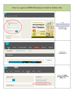


© Copyright 2026