
New York Design & Installation Manual June 2014 www.eljen.com
Geotextile Sand Filter New York Design & Installation Manual CORPORATION Innovative Environmental Products & Solutions Since 1970 June 2014 www.eljen.com Table of Contents Subject Page Terms and Definitions 3 GSF System Description 6 1.0 Basic System Design 7 2.0 Trench Configuration Sizing 10 3.0 Bed Configuration Sizing 13 4.0 Repair and Replacement System Sizing 16 5.0 GSF Sand Filter Design 20 6.0 Systems Designed for Level Sites 22 7.0 Systems Designed for Sloped Sites 23 8.0 Dosed or Pumped Systems 24 9.0 System Venting for Waivered Systems 25 10.0 Required Notes on Design Plans 26 11.0 System Installation Guidelines 27 12.0 Design for Replacement Systems 34 13.0 Trouble Shooting GSF Installation Tables 35 Page Table 1: B43 GSF Residential Trench Sizing Table – Linear Feet Per System 10 Table 2: B43 GSF Residential Trench Sizing Table – Modules Per System 10 Table 3: B43 GSF Residential Bed Sizing Table – Square Feet Absorption Area Per System 13 Table 4: B43 GSF Residential Bed Sizing Table – Modules Per System 13 Table 5: B43 GSF Repair & Replacement Bed Sizing Table – Square Feet Per System 17 Table 6: B43 GSF Repair & Replacement Bed Sizing Table – Modules Per System 17 Table 7: B43 GSF Sand Filter Sizing Using Gravel Based Design Drawings 20 Page Figure 1: GSF System Operation 6 Figure 2: Example Sizing of a Trench System 12 Figure 3: Example Sizing of a Bed System 15 Figure 4: Example Sizing of a Repair & Replacement Bed System 19 Figure 5: Example GSF Sand Filter Cross Section 21 Figure 6: Example GSF Sand Filter Plan View 21 Figure 7: Vertical Separation to Limiting Conditions 36 Figure 8: B43 GSF Trench Cross Section 36 Figure 9: Multiple Trench Cross Section 37 Figure 10: Shallow Trench Cross Section 37 Figure 11: Simple Trench with Center Loading Distribution Box 38 Figure 12: Trench Configuration for a Sloping Site / Avoiding Rock Out Crops and Trees 38 Figure 13: Drop Box Outlet Setup 39 Figure 14: Equal Loading Outlet Setup in a Dosed Distribution Box 40 Figure 15: B43 GSF Level Absorption Bed Installation Cross Section 41 Figure 16: B43 GSF Typical Level Absorption Bed Design Plan View 41 Figure 17: Air By-Pass Line Plan View for Venting of Pumped Systems 42 Figure 18: Air By-Pass Line Cross Section for Venting of Pumped Systems 42 Figure 19: Vent Detail for Gravity and Demand Dosed Distribution Systems 43 Figure 20: Vent Detail for Looped Bed Systems 43 2014 New York GSF Design & Installation Manual 2 www.eljen.com Terms and Definitions Appendix 75-A Absorption Field Area B43 This appendix represents the minimum design standards for onsite wastewater treatment systems serving residential properties and receiving sewage without the admixture of industrial wastes or other wastes as defined in Environmental Conservation Law, Section 17-0701, in quantities of less than 1,000 gallon per day (gpd) in the State of New York. The area to which wastewater is distributed over the GSF modules for infiltration into the soil. The GSF module model which measures 36” W x 48” L x 7” H in size. Bio-Matt™ Fabric Special filter fabric within the Geotextile Sand Filter Modules upon which the primary biomat layer forms as shown in Figure 1. Cover Fabric The anti-siltation geotextile cover fabric provided by the manufacturer that is placed over the GSF modules to keep out soil while allowing the exchange of gases and moisture as shown in Figure 1. Cuspated Core The rigid plastic core of a GSF module. It separates the geotextile fabric and creates downward infiltration channels and upward aeration channels to provide primary filtration and biological treatment of the septic effluent. The curvilinear shape of the cuspations offers increased treatment surface area and greater effluent storage. Design Flow The estimated daily flow that is used to size a GSF system is defined in Appendix 75-A.3, Table 1, ranging from 110 gallons per bedroom to 150 gallons per bedroom depending on use of water conserving fixtures. Individual Counties may have their own flow requirements. Distribution Box (Or D-Box) a plastic, fiberglass or concrete box that receives effluent from a septic tank and splits the flow to pipes placed above the GSF modules. For equal distribution, the outlet pipe orifices are typically set at the same elevation to equalize the flow to each line. The distribution box method is only used when the receiving GSF modules are at the same elevation. See Appendix 75-A.7 for additional state required guidelines. Drop Box A plastic, fiberglass or concrete box that is used on sloped systems where the elevation of the incoming line is higher than that of the outgoing distribution and outgoing spillover lines. This allows the loading of upper most trenches/rows in the system prior to loading lower trenches/rows. EHGWT The Estimated High Ground Water Table is the elevation of saturated condition as measured or as estimated from evaluation of soil color and soil redoximorphic features. Flow Equalizer Special devices placed in the discharge side of distribution pipes on the distribution box to minimize effects of settling and out of level installation. Other similar devices include Speed Levelers and Dial-A-Flow that permit the adjustment in the invert (outlet) elevation in each distribution pipe. GSF The Eljen Geotextile Sand Filter modules and the 6-inch Specified Sand layer along the base and sides of the modules. GSF Module The individual module of a GSF system. The module is comprised of a cuspated plastic core and corrugated geotextile fabric. LTAR Long Term Acceptance Rate (LTAR) is the average equilibrium absorption rate for effluent in a system, usually expressed in gallons per day per square foot. It should not be confused with the design loading rate specified in Table 4B for Trenches and Table 5 for absorption beds as defined in Appendix 75-A. 2014 New York GSF Design & Installation Manual 3 www.eljen.com Terms and Definitions Serial Distribution Designs common to sloping sites where GSF lines that are laid on contour and receive effluent from a series of drop boxes at different elevations. Effluent floods up-slope lines and then spills excess effluent to down-slope lines. Non-perforated pipe placed on undisturbed soil connects successive down-slope trenches. See Appendix 75-A.7.2 and Figure 12 of this manual for drop box layout for sloping sites in this manual. Eljen recommends serial distribution utilizing drop boxes on sloped sites. Specified Sand To ensure proper system operation, the system must be installed using ASTM C33 sand with less than 10% passing #100 sieve and less than 5% passing #200 sieve. Listed below is a chart outlining the sieve requirements for the Specified Sand as required by Eljen. ASTM C33 Sand Specification Sieve Size Sieve Square Opening Size Specification Percent Passing (Wet Sieve) 0.375" #4 #8 #16 #30 #50 #100 #200 9.5 mm 4.75 mm 2.36 mm 1.18 mm 600 µm 300 µm 150 µm 75 µm 100.0 -100.0 95.0 - 100.0 80.0 - 100.0 50.0 - 85.0 25.0 - 60.0 5.0 - 30.0 < 10.0 < 5.0 STE Septic Tank Effluent (STE) is anaerobically digested effluent that is discharged to a Geotextile Sand Filter module for further treatment. Width & Length The system width is the sand dimension perpendicular to the GSF module rows. The system length is measured parallel to the rows of GSF modules. Wire Clamps Clamps used to secure perforated pipe above the GSF modules. 2014 New York GSF Design & Installation Manual 4 www.eljen.com Introduction This manual provides design and installation information for the Eljen GSF Geotextile Sand Filter system using the B43 GSF module. Typical design layouts and installation instructions are included in this manual. GSF systems must be designed and constructed according to the current edition of the New York Department of Health Appendix 75-A Wastewater Treatment Standards – Residential onsite systems and Individual Residential Wastewater Treatment Systems Design Handbook. Please check with your local health department or local code enforcement officer for any additional requirements for the design and installation of the GSF system. For design standards for specially engineered dosing systems or general design questions, contact Eljen’s Technical Resource Department at 1-800-444-1359. Commercial systems are beyond the scope of Appendix 75-A. If you have a commercial system requirement, contact Eljen Corporation’s Technical Resource Department at 1-800-444-1359 for additional information and design criteria regarding these systems. The Eljen GSF system technology is based on research conducted by nationally recognized engineering scientists from the University of Connecticut. Eljen Corporation has over 30 years of success in the onsite wastewater industry, with tens of thousands of systems currently in use. The GSF is recognized by industry leaders as one of the most reliable treatment technology in the marketplace today. The system specifications in this manual are founded on this research and history of installations of the GSF worldwide. The GSF technology is based on scientific principles which state that improved effluent quality provides increased soil absorption rates. GSF’s proprietary two-stage Bio-Matt™ pre-filtration process improves effluent quality while increasing reliability and ease of operation. Third-party independent testing data based on NSF/ANSI Standard 40 Protocol has shown that the Eljen GSF provides advanced treatment of septic tank effluent to better than secondary levels. The Eljen GSF Geotextile Sand Filter 2014 New York GSF Design & Installation Manual 5 www.eljen.com GSF System Description The Eljen GSF Geotextile Sand Filter system is a cost-effective upgrade from other septic technologies. Comprised of a proprietary two-stage Bio-Matt™ pre-treatment process, the geotextile modules apply a betterthan-secondary aerobic effluent to the soil, increasing the soil’s ability to accept the effluent. The result is superior treatment in a smaller soil absorption area. How the GSF System Works Primary Treatment Zone Perforated pipe is centered above the GSF module to distribute septic effluent over and into corrugations created by the cuspated core of the geotextile module. Septic effluent is filtered through the Bio-Matt fabric. The module’s unique design provides increased surface area for biological treatment that greatly exceeds the module’s footprint. Open air channels within the module support aerobic bacterial growth on the modules geotextile fabric interface, surpassing the surface area required for traditional absorption systems. An anti-siltation geotextile fabric covers the top and sides of the GSF module and protects the Specified Sand and soil from clogging, while maintaining effluent storage within the module. Secondary Treatment Zone Effluent drips into the Specified Sand layer and supports unsaturated flow into the native soil. This Specified Sand/soil interface maintains soil structure, thereby maximizing the available absorption interface in the native soil. The Specified Sand supports nitrification of the effluent, which reduces oxygen demand in the soil, thus minimizing soil clogging from anaerobic bacteria. The Specified Sand layer also protects the soil from compaction and helps maintain cracks and crevices in the soil. This preserves the soil’s natural infiltration capacity, which is especially important in finer textured soils, where these large channels are critical for longterm performance. Native soil provides final filtration and allows for groundwater recharge. FIGURE 1: GSF System Operation 2014 New York GSF Design & Installation Manual 6 www.eljen.com 1.0 Basic System Design Jurisdiction: Please contact the local health department, watershed agencies, or Code Enforcement Officer for site specific information to determine if there are any additional local design requirements beyond the requirements of Appendix 75-A. Absorption Field Size: Eljen requires residential systems use a recommended minimum of 5 B43 modules per bedroom in either a trench or bed configuration. Tables 1 and 2 on Page 10 define the minimum trench system length and estimated number of modules respectively. The system size is based on dividing the design flow by the application rates given in Table 4B of Appendix 75-A and then applying Eljen’s 6 square foot per linear foot (6 sf/ft) rating from Appendix 75-A.8 (c)(3)(iii) and minimums set in this manual. This will determine the minimum trench length needed for each system. Trenches provide the most efficient design and minimize quantities of Specified Sand required for installation. In trench designs, a minimum of 6 inches of Specified Sand is required underneath and around the perimeter of the module row in the trench. Page 11 of this manual contains step-by-step sizing procedures for trench systems. Tables 3 and 4 on Page 13 of this manual define the required absorption bed bottom area and the number of modules in a bed configuration respectively. The same minimum number of modules is required by Eljen in beds as specified in a trench for a given site. Depending on the number of rows, the length and total number of modules will frequently increase in order to maintain an equal number of modules in each row. The footprint is based on the infiltrative area calculated by dividing the design flow by the application rates given in Table 5 of Appendix 75-A. In bed systems, the spacing between module rows will vary depending on system geometry. A minimum of 12 inches of Specified Sand is required around the perimeter of the module rows and a minimum of 12 inches of Specified Sand separating module rows. Equal numbers of modules are required in each row for bed applications. Page 14 of this manual contains step-by-step sizing procedures for bed systems. Proposed Repair and Replacement system sizing shown in Tables 5 & 6 on Page 17 represent the recommended minimum number of units and system area. Proposed sizing for Repair and Replacement bed systems must be approved by the local health official if required. Eljen recommends that Repair and Replacement bed systems are installed as “long and thin” as possible when site conditions allow. Vertical Separation: As required by New York rules, in-ground designs require a minimum of 4 feet of useable soil above bedrock, unsuitable soil, and seasonal high groundwater. The highest limiting condition on the upslope side of the trench shall be at least 2-feet below the 6-inch Specified Sand layer as shown in Figure 6. Specified Sand for Trench and Bed Systems: The first 6 inches of Specified Sand immediately under, between rows, and around the perimeter of the GSF system shall be an ASTM C33 Washed Concrete Sand With Less Than 10% Passing a #100 Sieve And Less Than 5% Passing a #200 Sieve. Please place a prominent note to this effect on each design drawing. See Page 4 of this manual for more information on the ASTM C33 sand specification. Fill for Shallow Trench Systems: As specified in 75-A.8.e, Eljen GSF systems may be installed on a plowed ground surface with 2-feet of suitable soil between the bottom of the 6-inch Specified Sand layer and the identified limiting conditions or restrictive soils. Specified Sand is place in the trenches in contact with the native soils. The total depth of fill is determined by the elevation of the base of the GSF Specified Sand layer and should not exceed 24 inches above the ground surface Additional fill is placed between the trenches to an elevation of 12 inches above the module by using a light weight track machine. The cover fill must demonstrate a percolation rate similar to the in situ while not exceeding the in situ soils permeability. The cover fill normally includes a 4-inch to 6-inch layer of top soil that supports growth of a robust vegetative cover capable of withstanding dry periods. System design and layout follow the requirements for level or sloping site trenches with sizing based on the receiving soil percolation rate and 6 square feet per linear foot module rating in a Specified Sand lined trench. Minimum trench center spacing is 8 feet on center based on trench separation of 4 feet of native soil. Designers are recommended to specify greater trench spacing in slower soils where they seek to insure hydraulic independence of each row of modules. Placing GSF Modules: Each row of modules is laid level and end to end on top of a 6-inch minimum layer of Specified Sand. No mechanical connection is required between the GSF modules. 2014 New York GSF Design & Installation Manual 7 www.eljen.com 1.0 Basic System Design Distribution Pipe: SDR 35 or equivalent is required. Place perforated distribution pipe on top of GSF modules with holes at the 5 and 7 o’clock positions. Complete system piping with non-perforated SDR 35 pipe and fittings. Refer to Sections 2.0 and 3.0 for level and serial piping details respectively. Secure pipe to GSF modules with provided wire clamps, one clamp per Eljen module with both legs of the clamp against the sides of the pipe. Distribution Box or D-Box: Set gravity system d-box outlet inverts a minimum of 1/8-inch per foot distance above invert of distribution pipe over the modules (2 inches minimum for pumped systems). The fill below the distribution box and pipes connecting to it must be compacted to prevent settling. When pumped systems are designed, specify oversized distribution boxes with baffles or velocity reduction piping. Cover Fabric: Eljen provides an anti-siltation geotextile fabric with the system that is placed over the top and sides of the module rows to prevent long-term siltation and failure. Cover fabric substitution is not allowed. Fabric should drape vertically over the pipe and must neither block holes nor be stretched from the top of the pipe to the outside edge of the modules. “Tenting” will cause undue stress on fabric and pipe. Loose fabric could lead to blockage of pipe drain holes. Backfill Grading and Storm water Management: Carefully place backfill over the modules, followed by loam to complete a total minimum depth of 12 inches as measured from the top of the modules. Systems with total cover that exceeds 18 inches as measured from the top of the module shall be vented at the distal (far) end of the system. Backfill with suitable native soil that is clean and devoid of rocks larger than 2 inches. Finish grade to divert surface runoff from the absorption field area. Finish grade to prevent surface ponding above and upslope of the absorption system. Seed loam to protect from erosion. Designers must divert storm water from impervious surfaces around the absorption system. Where storm water infiltration may create a seasonal perched water table, curtain drains may also be required upslope of the absorption system. Additional Factors Effecting Residential System Design: Homes with expected higher than normal water due to luxury fixtures should have an increased septic tank capacity and/or multiple compartment tanks and larger effluent absorption areas. Features that should be addressed by the designer include: Homes with Jacuzzi style tubs and other high water use fixtures such as multiple shower heads, etc. Group home or day care facilities with expected higher than normal occupancy and water consumption. Homes with water conditioner backwash. Diversion from septic tank required, see Section 1.0. Homes with in-sink garbage disposals or Jacuzzi style tubs must have an additional 250 gallon sized tank based on Appendix 75-A requirements. Designers should use discretion when there are multiple additional factors involved. Increase tank/system size in proportion to excess flow. Multi-compartment and or Dual tanks in series provide the best performance with better retention and separation of solids due to attenuation of flow. System Geometry: Design systems as long and narrow as practical along site contours to minimize ground water mounding especially in poorly drained, low permeability soils. Systems should be designed level with equal length and number of modules per row. Garbage Disposals: Design drawings shall include a note “Garbage Disposals Shall Not Be Used with This System.” If owner insists on using a garbage disposal, use a 2 compartments septic tank and increase tank size by 250 gallons. An appropriate sized septic tank effluent filter must also be used. Failure to adhere to these recommendations could void product warranty. 2014 New York GSF Design & Installation Manual 8 www.eljen.com 1.0 Basic System Design Water Conditioners: Water conditioners can adversely affect septic tank treatment and add to the hydraulic load of the absorption field area. See 75-A.3 for DOH recommendations. Discharge from residential water conditioners shall be into a separate alternative disposal system integrated with a storm water groundwater recharge system. The location shall be as far as possible from surface aquifer wells and the GSF system. Failure to adhere to these recommendations could void product warranty. System Venting: All systems require sufficient oxygen supply to the GSF system to maintain proper long term effluent treatment. If a p-trap is installed between the septic tank and the home it should be removed to allow air to flow from the GSF up through the home vent. The following situations require a waiver and venting at the distal (far) end of the GSF system: Any system approved with more than 18 inches of total cover as measured from the top of the modules to finished grade. Any pump systems approved with a depth greater than 18 inches require by-pass lines from the distribution box back to the pump station riser or septic tank riser as shown in Figures 17 and 18 on Page 42. This will ensure continuity of air flow around the pump station or septic tank and back up the home vent stack. Vehicular Traffic: All vehicular traffic is prohibited over the GSF system. Appropriate markers and barriers such as fencing, bollard or landscape timber should be used to prevent vehicular traffic from driving over the GSF System. Wheel traffic can crush distribution pipes above the modules and result in blockage and loss of effluent delivery to parts of the system. Septic Tanks: Many designers are now specifying dual compartment septic tanks or dual tanks installed in series for all their systems. Eljen supports this practice as it helps to assure long system life by reducing suspended solids and BOD to the absorption field area. Gas baffles or effluent filters are also recommended. Listed in the chart below are the septic tank capacity guidelines from Appendix 75-A.6, Table 3. Minimum Septic Tank Capacities Number of Bedrooms Minimum Tank Capacity (Gallons) Minimum Liquid Surface Area (Square Feet) 1-3 1,000 27 4 1,250 34 5 1,500 40 6 1,750 47 NOTE: Tank size requirements for more than six bedrooms shall be calculated by adding 250 gallons and seven (7) square feet of surface area for each additional bedroom. A garbage grinder or spa tub shall be considered equivalent to an additional bedroom for determining tank size. Septic Tank Filters and Risers: Wastewater effluent filters are required as a means of preventing solids from leaving the septic tank and encouraging management of the tank solids. Eljen recommends that access risers to grade be used on any septic tank with a filter to provide easy access for inspection and maintenance. 2014 New York GSF Design & Installation Manual 9 www.eljen.com 2.0 Trench Configuration Sizing To determine the minimum linear feet of trench required per Appendix 75-A, use Table 1 and identify the soil classification rating and then the number of bedrooms and the associated design flow of the dwelling. The intersection of these rows and columns will define the minimum linear feet of trench required for the system. Table 1: B43 GSF Trench Sizing Table - Minimum Linear Feet per System* Based on 6 sf/lf Sizing Credit Percolation Rate (Min/In) Application Rate (GPD/SF) 1-5 6-7 8-10 11-15 16-20 21-30 31-45 46-60 1.2 1.0 0.9 0.8 0.7 0.6 0.5 0.5 2 Bedroom 3 Bedroom 4 Bedroom Flow Rate (Gal/Day) 220 260 300 40 40 42 40 44 50 41 49 56 46 55 63 53 62 72 62 73 84 74 87 100 82 97 112 Flow Rate (Gal/Day) 330 390 450 60 60 63 60 65 75 62 73 84 69 82 94 79 93 108 92 109 125 110 130 150 123 145 167 Flow Rate (Gal/Day) 440 520 600 80 80 84 80 87 100 82 97 112 92 109 125 105 124 143 123 145 167 147 174 200 163 193 223 Each Additional Bedroom Flow Rate (Gal/Day) 110 130 150 20 20 21 20 22 25 21 25 28 23 28 32 27 31 36 31 37 42 37 44 50 41 49 56 * The table above represents the minimum length of a trench based on Gallons/Day, respective application rates, and minimum modules required per bedroom. It does not take into account module length and required Specified Sand at the end of the trench row. All final system lengths must add 1-foot of length to compensate for the 6-inches of Specified Sand required at the end of each system row. To determine the number of modules required for the system, use Table 2 and identify the soil classification rating and then the number of bedrooms and the associated design flow of the dwelling. The intersection of these rows and columns will define the number of modules required for the system. Table 2 has been adjusted to provide an Eljen required minimum of 5 modules per bedroom and has been rounded up to the next full module in systems that had partial modules as calculated to meet NYDOH sizing requirements. A step by step sizing procedure for the sizing of trench systems is on Page 11 of this manual. Table 2: B43 GSF Trench Sizing Table - Modules per System Based on 6 sf/lf Sizing Credit 2 Bedroom 3 Bedroom 4 Bedroom Flow Rate (Gal/Day) 220 260 300 Flow Rate (Gal/Day) 330 390 450 Flow Rate (Gal/Day) 440 520 600 Each Additional Bedroom Flow Rate (Gal/Day) 110 130 150 Percolation Rate (Min/In) Application Rate (GPD/SF) 1-5 1.2 10 10 11 15 15 16 20 20 21 5 5 6 6-7 1.0 10 11 13 15 17 19 20 22 25 5 6 7 8-10 0.9 11 13 14 16 19 21 21 25 28 6 7 7 11-15 0.8 12 14 16 18 21 24 23 28 32 6 7 8 16-20 0.7 14 16 18 20 24 27 27 31 36 7 8 9 21-30 0.6 16 19 21 23 28 32 31 37 42 8 10 11 31-45 0.5 19 22 25 28 33 38 37 44 50 10 11 13 46-60 0.5 21 25 28 31 37 42 41 49 56 11 13 14 2014 New York GSF Design & Installation Manual 10 www.eljen.com Residential Sizing Procedure for Trench Systems Note: Refer to Sizing Tables 1 and 2 on Page 10 for residential trench systems or Reference Appendix 75-A.8 and Table 4B from Appendix 75-A for absorption trench design and installation requirements. This design example is for illustration purposes only. All numbers can be rounded up to make designing and installing easier. Please contact Eljen Corporation with any questions. Procedure 1. Define the flow and absorption trench bottom area requirements: Use Table 1, on Page 10, of this manual to identify the flow and minimum linear feet of GSF trench required. Use the linear footage value where the percolation rate of the site intersects the number of bedrooms for the associated design flow of the dwelling. Or use Appendix 75-A, Table 4B, to determine the appropriate application rate and complete the following calculations: o Design Flow per Bedroom x Number of Bedrooms = Daily Flow Rate (gpd). o Daily Flow Rate (gpd) ÷ Application Rate (gpd/ft ) = Required Trench Bottom Area (ft ). o Required Trench Bottom Area (ft ) ÷ 6 ft /lf (GSF Module Rating) + 1’ for the sand envelope at the beginning and end of the trench = Minimum linear feet of trench required for the system. 2 2 2 2 Example Calculation: 3 bedrooms, 110 gpd/br with a percolation rate of 13 mpi: 2. 110 gpd/br x 3 br = 330 gpd daily flow rate. 330 gpd daily flow rate ÷ 0.80 gpd/ft application rate = 412.5 ft trench bottom area required. 412.5 ft required trench bottom area ÷ 6 ft /lf (GSF module rating) = 68.75 linear feet of trench required rounded up to 69’. 2 2 2 2 Estimate the number of GSF modules and define the row and trench length: Use Table 2, on Page 10, of this manual and identify the number of GSF modules required for the system. Find the value where the percolation rate of the site intersects the number of bedrooms and the associated design flow of the dwelling. Choose the number of trenches desired and round up to the same number of modules per trench if required. Or take the linear feet required for the system from Step 1 ÷ 4 ft length per module = number of GSF modules for the system. Choose the longest possible trench design keeping the same number of modules per trench. Example Calculation: 69 linear feet of trench required ÷ 4 ft length per module = 17.25 GSF modules. Using 3 module rows for the system, round up to 6 modules per row if there is room for a total of 18 modules for the system. Note: Continued on next page. 2014 New York GSF Design & Installation Manual 11 www.eljen.com Residential Sizing Procedure for Trench Systems 3. Define the trench length: Define the trench length based on the number of modules plus 1’ for the sand at each end of the trench (6” at each end): Example Calculation: 6 modules x 4’ module length + 1’ = 25’ per trench. Or for minimum size trench length based on total trench length required by Appendix 75-A complete the following calculations: o Divide total trench length by the number of trenches and maximize the number of modules that will fit in each trench. Example Calculation: 69’ ÷ 3 trenches = 23’ per trench. Number of Modules = 23’ trench length ÷ 4’ per module = 5.75 per trench, rounded down to 5 modules per trench. The module length = 5 modules x 4’ length per module = 20’. Specified Sand at each end of the trench = (23’ trench length – 20’ module row length) ÷ 2 = 18” of Specified Sand at each end of the trench. The system designer can decide how to configure the system based on site characteristics. In the example listed above, possible designs could include: A single row of modules with optional distribution box at the beginning of the trench used for inspection. A “butterfly” configuration, one row of modules in a single trench line with a distribution box located at the center of the system. Multiple trench configurations with equal number of modules in each trench following a distribution box. Multiple trenches on a hillside using drop boxes ahead of unequal length trenches. Add up to 18 inches of Specified Sand at the end of rows, instead of modules, in systems that “come close” to meeting trench length minimums. Figure 2: Example Sizing of a Trench System 3 bedrooms – 110 gpd/br – Percolation rate of 13 mpi ASTM C33 SAND 48" 48" 36" SEPTIC 6" 4' MINIMUM NATIVE SOIL TANK ASTM C33 SAND 6" 37' 2014 New York GSF Design & Installation Manual 12 www.eljen.com 3.0 Bed Configuration Sizing To determine the square feet of absorption bottom area required for the bed system, use Table 3 and identify the soil classification rating and then the number of bedrooms and associated design flow of the dwelling. The intersection of these rows and columns will define the square feet of absorption area required for the bed system. Table 3: B43 GSF Bed Sizing Table - Square Feet of Absorption Area per System 2 Bedroom 3 Bedroom 4 Bedroom Flow Rate (Gal/Day) 220 260 300 Flow Rate (Gal/Day) 330 390 450 Flow Rate (Gal/Day) 440 520 600 Each Additional Bedroom Flow Rate (Gal/Day) 110 130 150 0.95 232 274 316 347 411 474 463 547 632 116 137 158 6-7 0.80 275 325 375 413 488 563 550 650 750 138 163 188 8-10 0.70 314 371 429 471 557 643 629 743 857 157 186 214 11-15 0.60 367 433 500 550 650 750 733 867 1000 183 217 250 16-20 0.55 400 473 545 600 709 818 800 945 1091 200 236 273 0.45 489 578 667 733 867 1000 978 1156 1333 244 289 333 Percolation Rate (Min/In) Application Rate (GPD/SF) 1-5 21-30 > 30 Note: Design with Trench Configurations - Not Acceptable for Bed Configurations Under Appendix 75-A To determine the number of modules required for the bed system, use Table 4 and identify the soil classification rating and then the number of bedrooms and associated design flow of the dwelling. The intersection of these rows and columns will define the number of modules required for the bed system. These sizing tables have been adjusted to provide an Eljen required minimum of 5 modules per bedroom, and have been rounded up to the next full module in systems that had partial modules as calculated to meet DOH sizing requirements. A step by step sizing procedure for the sizing of bed systems is on Page 14 of this manual. Lower absorption rates assigned by DOH for beds in heavier clay loam soils allow greater spacing of module rows. This lower density of modules disperses the effluent from each row over a larger area and thereby reduces the application of effluent onto the soil. For very large beds call Eljen for more information on how the effluent can be managed to improve dispersion using gravity or dosed d-box designs. Table 4: B43 GSF Bed Sizing Table - Modules per System Percolation Rate (Min/In) Application Rate (GPD/SF) 2 Bedroom 3 Bedroom 4 Bedroom Flow Rate (Gal/Day) Flow Rate (Gal/Day) Flow Rate (Gal/Day) Each Additional Bedroom Flow Rate (Gal/Day) 220 260 300 330 390 450 440 520 600 110 130 150 1-5 0.95 10 10 11 15 15 16 20 20 21 5 5 6 6-7 0.80 10 11 13 15 17 19 20 22 25 5 6 7 8-10 0.70 10 13 14 16 19 21 21 25 28 6 7 7 11-15 0.60 12 14 16 18 21 24 23 28 32 6 7 8 16-20 0.55 14 16 18 20 24 27 27 31 36 7 8 9 21-30 0.45 16 19 21 23 28 32 31 37 42 8 10 11 > 30 Note: Design with Trench Configurations - Not Acceptable for Bed Configurations Under Appendix 75-A 2014 New York GSF Design & Installation Manual 13 www.eljen.com Residential Sizing Procedure for Bed Systems Note: Refer to Sizing Tables 3 and 4 on Page 13 for residential bed systems or reference Appendix 75-A.8(g) and Table 5 from Appendix 75-A for absorption bed design and installation requirements. This design example is for illustration purposes only. All numbers can be rounded up to make designing and installing easier. Please contact Eljen Corporation with any questions. Procedure 1. Define the flow and absorption bed basal area requirements: Define the design flow based on the flow per bedroom and home size. Use Table 3, on Page 13, of this manual and identify the basal bed area requirement by finding the square footage value where the percolation rate of the site intersects the number of bedrooms and the associated design flow of the dwelling. Or use Appendix 75-A, Table 5, to determine the appropriate application rate and the following 2 2 calculation: Daily Flow Rate (gpd) ÷ Application Rate (gpd/ft ) = Required Bed Bottom Area (ft ). Example Calculation: 4 bedrooms – 110 gpd/br – Percolation rate of 15 mpi. 110 gallons per bedroom x 4 BR = 440 gpd. 440 gpd ÷ 0.60 gpd/ft = 733 ft Absorption Bed Basal Area Required. 2 2 2. Use Table 4, on Page 13, of this manual and identify the total number of GSF modules for the system by finding the value where the percolation rate of the site intersects the number of bedrooms for the specified design flow of the dwelling. Example Calculation: Using Table 4, with a 4-bedroom home, in 20 minutes per inch percolation rate soil, with a design flow of 440 gpd. The application rate equals 0.60 gpd/sf and number of modules required equals 23 modules. 3. Estimate the number of modules and system length based on equal number of modules per row. For example; if 23 modules are required use 2 rows of 12 B43 modules. 4. Define the bed length: Based on site conditions and the number of modules needed for the system, choose the number of module rows for the system. Define the bed length by dividing the total number of modules by the number of rows chosen, round up the number of modules to make all rows equal. Ensure that bed system geometry is narrow with no more than three rows of modules in finer textured soils. Multiply the number of modules per row by 4 feet (the length of a GSF module) and add 2 feet (for the specified sand on both ends). Number of modules (Table 4) ÷ number of rows = Modules per Row. Number of modules per row x 4 feet plus 2 feet = Bed Length. Note: Continued on next page. 2014 New York GSF Design & Installation Manual 14 www.eljen.com Residential Sizing Procedure for Bed Systems Example Calculation: For the above example, choose 2 rows with 12 B43 modules per row = 24 modules. (12 modules x 4’ module length) + (1’ sand perimeter) = 50 feet for the bed length. 5. Define the bed width: Take the Absorption Bed Basal Area (Footprint) ÷ Bed Length (Step 4) = Bed Width. Example Calculation: 2 Using 2 rows, the preferred narrow design = 733 ft ÷ 50 ft = 14.66 feet or round up to 15’ for ease of layout. Note: Exact measurements can always be used. 6. Determine the module row spacing in the bed: Spacing between rows = bed width ÷ number of rows = Center Spacing for level systems. Use 1/2 center spacing between the outside module rows and the side of the bed (or a minimum of 1 foot). Example Calculation: 15 feet ÷ 2 = 7.5’ Center-To-Center Module Row Spacing 7.5 ÷ 2 = 3.75’ spacing between the center of the outside module rows and the side of the bed. Figure 3: Example Sizing of a Bed System 4 bedrooms – 110 gpd/br – Percolation rate of 15 mpi 12" 3.75' SEPTIC 7.5' ASTM C33 SAND TANK 3.75' 50.0' 2014 New York GSF Design & Installation Manual 15 www.eljen.com 4.0 Repair and Replacement Bed System Sizing To determine the square feet of absorption bottom area required for the bed system, use Table 5 and identify the soil classification rating and then the number of bedrooms and associated design flow of the dwelling. The intersection of these rows and columns will define the square feet of absorption area required for the repair or replacement bed system. To determine the number of modules required for the bed system, use Table 6 and identify the soil classification rating and then the number of bedrooms and associated design flow of the dwelling. The intersection of these rows and columns will define the number of modules required for the bed system. General Guidelines for Repair and Replacement System Sizing Proposed Repair and Replacement system sizing shown in Tables 5 & 6 represent the minimum number of units and system area. Number of modules and system area can always be increased to meet local requirements and the needs of the design and site. Proposed sizing for Repair and Replacement bed systems must be approved by the local health official if required. Minimum number of Eljen B43 modules per bedroom is 5 B43 modules. Minimum edge to edge module spacing for Repair and Replacement bed systems is 12 inches. Maximum length per system row is 60 feet for gravity, 75 feet for pump dosing, and 100 for pressure distribution. Tables 5 & 6 are based on a minimum design flow of 150 gpd/bedroom. For lower flows, please contact Eljen Corporation for technical support. Eljen recommends that Repair and Replacement bed systems are installed as “long and thin” as possible when site conditions allow. System rows must use an equal number of modules per row. System area may need to be increased to accommodate additional units. 2014 New York GSF Design & Installation Manual 16 www.eljen.com 4.0 Repair and Replacement Bed System Sizing Table 5: B43 GSF Bed Sizing Chart for Remediation & Replacement Systems Minimum Square Feet of Absorption Area per System Percolation Rate (Min/In) Application Rate (Adjusted) (GPD/SF) 1-5 6-7 8-10 11-15 16-20 21-30 31-45 46-60 61-80 81-100 101-120 1.57 1.33 1.17 1.00 0.92 0.75 0.67 0.58 0.50 0.42 0.33 2 Bedroom 3 Bedroom 4 Bedroom Flow Rate (Gal/Day) 300 192 226 257 300 327 400 448 518 600 715 910 Flow Rate (Gal/Day) 450 287 339 385 450 490 600 672 776 900 1072 1364 Flow Rate (Gal/Day) 600 383 452 513 600 653 800 896 1035 1200 1429 1819 Each Additional Bedroom Flow Rate (Gal/Day) 150 96 113 129 150 164 200 224 259 300 358 455 Table 6: B43 GSF Bed Sizing Chart for Remediation & Replacement Systems Minimum Number of B43 Modules & Linear Feet per System Percolation Rate (Min/In) 1-5 6-7 8-10 11-15 16-20 21-30 31-45 46-60 61-80 81-100 101-120 Application Rate (Adjusted) (GPD/SF) 1.57 1.33 1.17 1.00 0.92 0.75 0.67 0.58 0.50 0.42 0.33 2 Bedroom 3 Bedroom 4 Bedroom Flow Rate (Gal/Day) 300 Flow Rate (Gal/Day) 450 Flow Rate (Gal/Day) 600 Each Additional Bedroom Flow Rate (Gal/Day) 150 Min Number of Modules Linear Feet Min Number of Modules Linear Feet Min Number of Modules Linear Feet Min Number of Modules Linear Feet 10 10 11 13 14 17 19 22 25 30 38 40 40 44 52 56 68 76 88 100 120 152 12 15 17 19 21 25 28 33 38 45 57 48 60 68 76 84 100 112 132 152 180 228 16 19 22 25 28 34 38 44 50 60 76 64 76 88 100 112 136 152 176 200 240 304 4 5 6 7 7 9 10 11 13 15 19 16 20 24 28 28 36 40 44 52 60 76 2014 New York GSF Design & Installation Manual 17 www.eljen.com 4.0 Repair and Replacement Bed System Sizing Note: Refer to Sizing Tables 5 and 6 on Page 17 for Repair and Replacement bed systems. Repair and Replacement bed systems must be approved by the local health official if required. This design example is for illustration purposes only. All numbers can be rounded up to make designing and installing easier. Please contact Eljen Corporation with any questions. Procedure 1. Define the flow and absorption bed basal area requirements: Define the design flow based on 150 gpd/bedroom. For lower flows, please contact Eljen Corporation for technical support. Use Table 5, on Page 17, of this manual and identify the basal bed area requirement by finding the square footage value where the percolation rate of the site intersects the number of bedrooms. Example Calculation: 4 bedrooms – 150 gpd/br – Percolation rate of 20 mpi. 150 gallons per bedroom x 4 BR = 600 gpd. 600 gpd ÷ 0.92 gpd/ft = 653 ft Absorption Bed Basal Area Required. 2 2 2. Use Table 6, on Page 17 of this manual and identify the total number of GSF modules for the system by finding the value where the percolation rate of the site intersects the number of bedrooms for the specified design flow of the dwelling Example Calculation: Using Table 6, with a 4-bedroom home, in 20 minutes per inch percolation rate soil, with a design flow of 600 gpd. The application rate equals 0.92 gpd/sf and number of modules required equals 28 modules. 3. Estimate the number of modules and system length based on equal number of modules per row. For example; if 28 modules are required use 2 rows of 14 modules. 4. Define the bed length: Based on site conditions and the number of modules needed for the system, choose the number of module rows for the system. Define the bed length by dividing the total number of modules by the number of rows chosen, round up the number of modules to make all rows equal. Ensure that bed system geometry is narrow with no more than three rows of modules in finer textured soils. Multiply the number of modules per row by 4 feet (the length of a GSF module) and add 2 feet (for the specified sand on both ends). Number of modules (Table 6) ÷ number of rows = Modules per Row. Number of modules per row x 4 feet plus 2 feet = Bed Length. Note: Continued on next page. 2014 New York GSF Design & Installation Manual 18 www.eljen.com 4.0 Repair and Replacement Bed System Sizing Example Calculation: For the above example, choose 2 rows with 14 B43 modules per row = 28 modules. (14 modules x 4’ module length) + (1’ sand perimeter) = 58 feet for the bed length. 5. Define the bed width: Take the Absorption Bed Basal Area (Footprint) ÷ Bed Length (Step 4) = Bed Width. Example Calculation: 2 653 ft ÷ 58’ = 11.25’ for a 2 row bed width. Note: All numbers can be rounded up to make designing and installing easier. 6. Determine the module row spacing in the bed: Spacing between rows = bed width ÷ number of rows = Center Spacing for level systems. Use 1/2 center spacing between the outside module rows and the side of the bed (or a minimum of 1 foot). Example Calculation: 11.25 feet ÷ 2 rows = 5.625’ Center-To-Center Module Row Spacing 5.625’ ÷ 2 rows = 2.8’ spacing between the center of the outside module rows and the side of the bed Note: Elevated or Mound systems can use minimum edge to edge spacing of 1 foot with a 1 foot sand perimeter to minimize module sand application area. Basal area must be sized according to Table 5. Figure 4: Example Sizing of a Repair and Replacement Bed System 4 bedrooms – 150 gpd/br – Percolation rate of 20 mpi 56' 12" 2.8' SEPTIC 5.625' ASTM C33 SAND TANK 11.25' 58.0' 2014 New York GSF Design & Installation Manual 19 www.eljen.com 5.0 GSF Sand Filter Design Appendix 75-A provides minimum specifications for sand filter design. The GSF modules replace aggregate and provide additional pretreatment capacity so only 12 inches of specified sand is required below the modules. This allows remediation of an existing sand filters with minimal, if any, sand replacement. The modules can be installed on the exposed clean sand with specified sand placed around the modules as required in any bed design. Minimum spacing of 12 inches between modules and 6 inches along the sides applies to all installations. Greater spacing is allowed for filters that exceed state minimum requirements shown in Table 5 of this manual. The following sizing of sand filters is based on the 2010 Appendix 75-A loading rate of 1.15 gallons per day per square foot. Sizing will vary based on required design flows. Minimum sizing required by Eljen is 15 B43 modules or 252 square feet. Figures 5 and 6 show the cross section and plan view for the filters. A minimum of 6 inches of specified sand filter sand is required on both sides and the end of each row of modules. Design guidance uses 24 square feet per module with the total number modules rounded up for an equal number of modules per row. Table 7: B43 GSF Sand Filter Sizing Using Gravel Based Design Bed Width (ft) 8 Number of Bedrooms Design Flow Gal/Day Square Feet of System Area (1.15) (gpd/sf) Required Sand Module Length (6 sf/lf) Number of Rows Number of Rows 2 2 3 4 3 4 Total Number of Modules Modules per Row 12 16 Bed Width (ft) 8 Number of Rows 2 3 4 Bed Length (ft) 12 16 Number of Rows 2 3 4 Total System Area (sf) 3 330 287 47.8 8 5 5 16 15 20 33 21 21 264 252 336 3 390 339 56.5 8 5 5 16 15 20 33 21 21 264 252 336 3 450 391 65.2 9 6 5 18 18 20 37 25 21 296 300 336 4 440 383 63.8 8 6 4 16 18 16 33 25 17 264 300 272 4 520 452 75.4 10 7 5 20 21 20 41 29 21 328 348 336 4 600 522 87.0 11 8 6 22 24 24 45 33 25 360 396 400 5 550 478 79.7 10 7 5 20 21 20 41 29 21 328 348 336 5 650 565 94.2 12 8 6 24 24 24 49 33 25 392 396 400 5 750 652 108.7 14 10 7 28 30 28 57 41 29 456 492 464 6 660 574 95.7 12 6 780 678 113.0 15 10 8 30 30 32 61 41 33 488 492 528 6 900 783 130.4 17 11 9 34 33 36 69 45 37 552 540 592 8 6 24 24 24 49 33 25 392 396 400 *Note: Minimum of 15 modules and 252 square feet required. Gravity application of the septic effluent is possible if the receiving sump uses a pump to apply the effluent to the receiving trenches. This setup allows recycling a fraction of the treated effluent back to the d-box that precedes the GSF filter. Use of an orifice splitting manifold allows adjustment of the recycle ratio. Contact Eljen if you have any questions on the design hydraulic splitting device. For dosed filter designs use 1 gallon per foot of media per dose. Contact Eljen if you have any questions on the source and design for these tanks. 2014 New York GSF Design & Installation Manual 20 www.eljen.com 5.0 GSF Sand Filter Design Figure 5: Example GSF Sand Filter Cross Section GRADE FOR PROPER DRAINAGE VEGETATIVE COVER TOPSOIL 12" MIN CLEAN BACKFILL 12" 12" ASTM C33 SAND >= 4" >= 2" 3" PEA GRAVEL 4" COLLECTION PIPE >= 24" HIGH GROUND WATER Figure 6: Example GSF Sand Filter Plan View DISTRIBUTION BOX NON-PERFORATED PIPE ASTM C33 SAND (TYP) DOSING 13' SPACING BETWEEN MODULE ROWS - 12" MIN SPACING BETWEEN BED SIDEWALL AND PERIMETER OF MODULES VARIES WITH 12" MINIMUM SEPARATION 12" MINIMUM 30' 2014 New York GSF Design & Installation Manual TANK 21 www.eljen.com 6.0 Systems Designed for Level Sites System Configurations: All GSF modules are placed in a trench configuration and preceded by an effluent flow-splitting box. The elevation of this box and outlet pipes depends on its distance from the modules and whether the system is dosed via pump, by proprietary dosing devices, or receives effluent that overflows by gravity directly from the septic tank. Trenches are normally spaced with 4 feet of undisturbed soil between each row of modules. 4 foot wide GSF trenches are rated by NYDOH at 6 square feet per linear foot and require a minimum of 6 inches of Specified Sand around the perimeter of the modules. For additional infiltrative capacity, without official sizing credit, use wider trenches and thus additional Specified Sand along each side of the modules. Bed systems operate on a principal similar to the absorption trench except that several laterals, rather than just one, are installed in a single excavation. In beds the NYDOH assumes bottom area absorption only and assigns a lower soil absorption efficiency based on Table 5 of Appendix 75-A. Lower absorption rates assigned by DOH for beds in heavier clay loam soils allow greater spacing of module rows. This lower density of modules disperses the effluent from each row over a larger area and thereby reduces the application of effluent onto the soil. For very large beds call Eljen for more information on how the effluent can be managed to improve dispersion using gravity or dosed d-box designs. Distribution Pipe Layout: Solid wall pipe is used to connect perforated lines to the distribution box. All distribution piping must meet a minimum 2500 pound crush test rating. In trenches, perforated SDR 35 or equivalent pipe runs along the center of the modules perpendicular to the single (up-side) cuspated plastic corrugations with pipe ends capped at the end of the trench as shown in Figures 8 and 9 of this manual. The pipe delivers effluent into the module rows and the transfer of effluent between full corrugations within the GSF module. In beds, the ends of the pipe are looped with solid wall SDR 35 or equivalent pipe at the distal (far) end of the bed as shown in Figure 15 of this manual. 2014 New York GSF Design & Installation Manual 22 www.eljen.com 7.0 Systems Designed for Sloped Sites On grades >8% and less than 15% Use Dosed Distribution Boxes or Gravity Drop Boxes Trench Distribution Options: If a dosed distribution box is specified, all trenches shall be equal length with each pair of trenches tied with a spill over at the distal end. Only one of each pair of lines shall receive effluent with the overflow at the distal end feeding the next down slope second trench. Serial distribution using drop boxes fully utilize uppermost trenches prior to spilling effluent into a lower row of modules. Trenches accept more or less effluent based on the flow rate into the modules and the row length. Systems with unequal trench lengths are possible, as shown in Figure 11 of this manual, with serial distribution as per Appendix 75-A.7. Easy access to all flow-splitting boxes is essential for monitoring system use, adjustment of flow or to rest any one trench. Module Placement and Spacing in Shallow Trench Configurations: Shallow trench designs use fill above the ground surface to protect and cover the GSF modules. Trenches are excavated after placement and stabilization of the fill material. In a sloped shallow trench configuration with Specified Sand on the soil surface, use a minimum of 48-inch spacing between adjacent module rows. Serially loaded (gravity or dosed) rows of modules are required to insure full utilization of the upper module rows. As the system matures, peak effluent flows will pass through the drop box to lower rows, keeping the effluent spread across the up slope rows of modules before utilizing down slope rows. Drop Boxes and Flow Control: Provide a Drop-Box at the beginning of the each row of modules in a serial distribution design. A box at the beginning of the lowest row is recommended so the expansion of the system is possible down slope. As noted previously, easy access to the drop boxes and distribution boxes is essential for monitoring purposes and future adjustment and resting of module rows if desired. Distribution Pipe Layout: Solid wall pipe is used to transfer effluent to and between drop boxes. Perforated SDR 35 or equivalent pipe runs along the center of the modules perpendicular to the single (upside) cuspated plastic corrugations. Curvilinear designs are possible with the modules turned to follow the ground contour as shown in Figure 16. The perforated pipe delivers effluent into the modules and helps transfer effluent between full corrugations within the modules. In shallow fill designs, the ends of module rows are connected to a spillover that transfers effluent to distal end of the next down slope even row. In below grade trenches perforated pipe ends are capped. 2014 New York GSF Design & Installation Manual 23 www.eljen.com 8.0 Dosed or Pumped Systems Pump Distribution Box: Oversized distribution boxes are recommended for dosed designs. Multiple boxes can be used and are connected to a header manifold that is engineered to split the flow based on the number of modules receiving effluent at one time. Large boxes allow for resting some lines by simply using a 90° elbow to exclude effluent while maintaining air flow. A force main connected to an elbow or sweep “T” in the box will help direct the effluent to the base of the box as shown in Figure 13. The elevation of the distribution box should be 2 inches or more above the perforated drain pipe resting on top of the modules. Speed Levelers or other adjustable elevation flow limiting inlets area required on all outlet lines. Continuity of air flow back through the home may require a separate line from the distribution box back to the riser on the dosing or septic tank for systems with greater than 18 inches of cover. Examples are shown in Figures 17 and 18. Dosing Design Criteria: Eljen requires the dosing volume be set to deliver a maximum of 4 gallons per B43 module per dosing cycle with low head high volume pumps preferred. Lines longer than 60 feet are required to be dosed with a maximum row length of 100 feet as per the requirements of Appendix 75-A.7 Higher flow rates and short dose cycle push the effluent down the line and thus disperse the effluent over a larger area. A valve on the force main is recommended to set the flow rate so that the orifices on the outlet pipes are submerged and the box does not overflow. Adjustment of the flow rate is likely needed if a row of modules are rested thus changing the number or outlets. Fewer outlets in the box force more effluent down each line and improve linear loading. Head loss and drain back volume must be considered in choosing the pump size and force main diameter. In absorption fields, single dosing units are required when the total trench length exceeds 500 feet. Alternate dosing units are required when the length exceeds 1,000 feet in accordance with Appendix 75-A regulations. Pressure Distribution: Pressure distribution uses small diameter pressurized laterals within a 4-inch perforated drain pipe. Orifice orientation in the pressure lateral shall be at the 12 o’clock position with drain holes at the 6 o’clock position. Use of 3/16-inch orifices is recommended on 4 foot centers. Standard design tables and figures developed for mound systems can be applied to the design of the pressure distribution networks and manifolds. The size of the lateral will depend on the length of the module row. Central manifolds may be required on larger systems to keep the distal discharge rates within 95% of the first orifice. Custom engineered designs that adjust the orifice spacing are required to equalize flow to trenches at different elevations. Engineering assistance is available from Eljen’s Technical Resource Department for these designs at 1-800-444-1359. Flushing ports are required at the distal end of all pressure distribution networks. Flushing valves and vents can be consolidated in larger systems by using valves on the outlet manifold. 2014 New York GSF Design & Installation Manual 24 www.eljen.com 9.0 System Ventilation for Waivered Systems Ventilated System: Oxygen supports more rapid digestion of solids captured by the GSF modules and more rapid absorption of effluent by the Specified Sand and soil. This Specified Sand filled space connects to downward facing cuspations within the GSF modules that remain open and support aerobic bacteria on the geotextile and in the open sand interface below. Open channels with extensive sidewall within the modules intermittently flood and drain, exposing the bacteria on these sidewalls to aerobic conditions whenever the system rests. Under normal operating conditions only a fraction of the modules and mini trenches receive effluent. The unused modules remain open and aerobic, ready to process peak flows. Distal End Vent: Very shallow systems can rely on diffusion of air into the system through the soil. Distal end vents are required absorption systems located under impervious surfaces or waivered systems deeper than 18 inches as measured from the top of the GSF module to finished grade. This will ensure proper aeration of the modules and Specified Sand. The extension of the distribution pipe at the distal end to an above ground vent feeds fresh air into the GSF system. Home plumbing operates under negative pressure due to hot water heating the pipes and reducing the density of air in the house vent. As hot air rises and exits the home, it pulls fresh air into the GSF. To maintain this air flow, it is important that air vents are located only on the distal end of the GSF pipe network. In the gravity fed GSF system, the vent is usually a 4-inch diameter pipe extended to a convenient location behind shrubs. Corrugated pipe can be used with the placement and grade such that any condensation that may accumulate in the pipe does not fill and thus close off this line. If the vent is extended, the pipe must not drain effluent and must have an invert higher than the system. Pump By-pass Line: If a pumped system with greater than 18 inches of cover or proposed is specified, an additional 2-inch by-pass line must be extended from the GSF system distribution box back to the riser on the septic tank or the pump tank. This maintains the continuity of air flow from the modules back through the house plumbing as shown in Figures 17 and 18. When venting a gravity or pump system, the use of a Granular Activated Charcoal (or Carbon) Filter will address any odor issues that may occur. Vent details for gravity and demand dosed systems are shown in Figure 19. 2014 New York GSF Design & Installation Manual 25 www.eljen.com 10.0 Required Notes on Design Plans 1. This design and construction requirement complies with Appendix 75-A and local health department regulations. 2. This design complies with and must be installed in accordance with the most current Eljen New York Design and Installation Manual. 3. This system is not designed for use with a garbage disposal. 4. This system is not designed for backwash from a water softener. 5. Organic material that can restrict flow must be removed for raised beds. The soil must be scarified to provide deep channels for the sand. A plowed interface on contour is recommended to prepare the soil for fill placement. 6. Scarify any smeared subsoil prior to fill placement. 7. Fill material shall meet or exceed State of New York Code requirements. All fill material shall be clean bank run sand, free of topsoil ,humus, and “dredging” directly beneath the GSF system. 8. ASTM C33 Specified Sand with less than 10% passing a #100 sieve and less than 5% passing a #200 sieve shall be place below and around the GSF modules, with 6 inches minimum underneath and 6 inches minimum surrounding the GSF modules in trench configurations. In bed systems, use 6 inches minimum underneath the modules with 12 inches minimum between module rows and 12 inches minimum around the perimeter of the modules. 9. Eljen provided geotextile cover fabric shall provide proper tension and orientation of the fabric around the sides of the perforated pipe on top of the GSF modules. Fabric should be neither too loose, nor too tight. The correct tension of the cover fabric is set by: Spreading the cover fabric over the top of the module and down both sides of the module with the cover fabric tented over the top of the perforated distribution pipe. Place shovel full’s of Specified Sand directly over the pipe area allowing the cover fabric to form a mostly vertical orientation along the sides of the pipe. Repeat this step moving down the pipe. 10. Backfill material shall be clean with no roots or stones larger than 2 inches in any dimension to a minimum depth of 8 inches over the GSF modules and final cover for vegetation of 4 inches to 6 inches of clean loam. 11. Any system which is more than 18 inches below finish grade as measured from the top of the module shall be vented. 2014 New York GSF Design & Installation Manual 26 www.eljen.com 11.0 System Installation Guidelines Important General Guidelines Reference Appendix 75-A and local health department regulations for design and construction requirements. Place the 7-inch tall Geotextile Sand Filter Modules on top of a 6 inches minimum level surface of ASTM C33 Specified Sand with less than 10% passing a #100 sieve and less than 5% passing a #200 sieve. You must use the Specified Sand as listed on Page 4 of this manual to ensure proper system operation. Specified sand placed along both sides and across the top of the GSF module ensures aeration of the modules. Additional sand placed above the module is recommended to maintain oxygen transfer to the system. Use the provided wire clamps to secure the approved perforated 4-inch diameter distribution pipe SDR 35 or equivalent to the top of each GSF modules. Cover the tops and sides of the modules along the entire length of each row with Eljen geotextile cover fabric prior to backfilling with Specified Sand. Where the percolation rate exceeds 30 minutes-per-inch or the soil texture is finer, the system should be built from one end to the other to avoid any compaction of the soil by the excavator. When backfilling the installation with native soil, stones 2 inches or larger must be removed. Finish by grading the area to divert storm water runoff away from the system. Do not drive backhoe wheels over GSF modules with less than 12 inches of cover over the distribution pipe. Driving or paving over the Geotextile Sand Filter area is prohibited. For shallow installations, lightweight track-mounted machines are best for setting the final grade. It is also permissible to back-blade the soil to set final minimum cover. Perimeter landscape timbers are also recommended to locate the shallow beds, thereby keeping vehicles off the system. Seeding and stabilizing the soil cover is required to protect the system from soil erosion. Where the elevation of the surface exceeds the natural grade, a block or landscape timber frame or sloping soil toe at a 3:1 grade can be used to help eliminate soil erosion and support maintenance of the stabilizing grass cover adjacent to the GSF system. For pumped systems, provide a well anchored distribution box with a velocity reduction tee or baffle. Venting of systems is required when there is more than 18 inches of cover material as measured from the top of the module to finished grade. Locate vent at the distal (far) end of the trench or bed. Systems installed at this depth require a waiver. 2014 New York GSF Design & Installation Manual 27 www.eljen.com In-Ground Trench and Bed System Installation Instructions Trench Configurations - Usable Percolation Rates 1 - 60 Minutes per Inch Bed Configurations - Usable Percolation Rates 1 - 30 Minutes per Inch 1. Reference Appendix 75-A and local health department regulations for design and construction requirements. Carefully layout the system components to maintain the required setbacks from the property boundary, home, system components, water systems (onsite and neighboring property), and other topographic boundaries. Define the location and elevation of the trench or bed based on limiting conditions such as bedrock or seasonal high water table elevation. Set the septic tank outlet elevation and pipe grades required to maintain flow to each component. 2. Prepare the site according to Appendix 75-A and local regulations. Do not install a system on saturated ground or wet soils that can smear during excavation. Keep heavy machinery off clay soils used for the GSF system as well as down-slope from the system where soil structure is critical for absorption and drainage of the treated effluent. 3. Plan all drainage requirements up-slope of the system. Set soil grades to ensure that storm water drainage and ground water is diverted away from the absorption area once the system is complete. 4. Excavate the trench or bed removing organic materials such as grasses and shrubs. Scarify the receiving layer to maximize the interface between the native soil and Specified Sand. 5. Minimize walking in the trench or bed prior to placement of the Specified Sand to avoid soil compaction. 6. Place Specified Sand in trench or bed refers to Page 4 for more information on the Specified Sand specification. The compacted Specified Sand height below the GSF module must be 6 inches minimum. 7. A hand tamper is sufficient to stabilize the sand below the GSF modules. Set a level surface for each row of modules on the surface of the Specified Sand using a 2-inch x 4-inch board and carpenter’s level or a laser before placing the modules. 8. Place GSF modules with the single piece of cuspated core in each geotextile corrugation and the PAINTED STRIPE FACING UP, end to end on top of the Specified Sand. 9. Provide distribution box(es) installed in accordance with Appendix 75-A and local regulations. Install flow equalizers in a gravity fed distribution box. Use speed levelers to equalize distribution between lines in dosed distribution box designs. 10. Use 4-inch SDR-35 or equivalent solid wall pipe from the distribution box to the perforated pipe above the GSF modules. 11. Center 4-inch SDR-35 or equivalent perforated distribution pipe lengthwise over modules with orifices at the 5 & 7 o’clock positions. 12. Secure distribution pipe to GSF modules using one Eljen wire clamp per module. Position legs of wire clamp on both sides of the perforated pipe. Push clamp ends straight down into up-facing core, through the fabric and into the underlying sand. 13. Install the manufacturer supplied cover fabric. Cover fabric placement requires setting the tension and orientation of the fabric around the sides of the perforated pipe on top of the GSF modules. If the fabric is too loose, it blocks the effluent from draining into the modules. If the fabric is too tight, it could tear if punctured by a sharp object and allow soil and sand to fall into the open corrugations of the modules. The correct tension of the cover fabric is set by: Spreading the cover fabric over the top of the module and down both sides of the module with the cover fabric tented over the top of the perforated distribution pipe. Place shovel full’s of Specified Sand directly over the pipe area allowing the cover fabric to form a mostly vertical orientation along the sides of the pipe. Repeat this step moving down the pipe. Anchor the cover fabric by placing Specified Sand along the sides and up to the top of the module and walk it in to ensure the cover fabric is secure in place. 2014 New York GSF Design & Installation Manual 28 www.eljen.com In-Ground Trench and Bed System Installation Instructions 14. Trench: Place 6 inches minimum of Specified Sand along the outside perimeter of the module(s) and 6 inches at the ends of each row. Sidewall separation between trenches shall be 4 feet of native soil. 15. Bed: Specified Sand placement will vary between modules rows and around the perimeter of the bed with a minimum of 12 inches of Specified Sand between module rows, along outside perimeter and at the ends of each module row. 16. Complete backfill with loam to 12 inches minimum over the GSF modules. Backfill exceeding 18 inches requires venting at the distal (far) end of the module row. Fill should be clean, porous, and devoid of large rocks. Fill shall have a percolation rate of 5 to 30 minutes per inch. Do not use wheeled equipment over the system. A light track machine may be used with caution, avoiding crushing or shifting of pipe assembly. Backfill from the upslope side. Maintain adequate fill depth below a light weight track machine to avoid crushing or disturbing the distribution pipes above the modules. 17. Finish grade to prevent surface ponding. Divert surface runoff and seed loam to protect from erosion. 2014 New York GSF Design & Installation Manual 29 www.eljen.com Shallow Trench System Installation Instructions All shallow trench systems require fill to cover and protect the modules as the base of the trench is less than 24 inches deep. Trenches are normally excavated after the fill has been placed over the absorption field area. The base of the trenches must be excavated into the native soil. 1. Reference Appendix 75-A and local health department regulations for design and construction requirements. Carefully layout the system components to maintain the required setbacks from the property boundary, home, system components, water systems (onsite and neighboring property), and other topographic boundaries. Define the location and elevation of the trench based on limiting conditions such as bedrock or seasonal high water table elevation. Set the septic tank outlet elevation and pipe grades required to maintain flow to each component. 2. Prepare the site according to Appendix 75-A and local regulations. Do not install a system on saturated ground or wet soils that can smear during excavation. Keep heavy machinery off clay soils used for the GSF system as well as down-slope from the system where soil structure is critical for absorption and drainage of the treated effluent. 3. Plan all drainage requirements above (up-slope) of the system. Set soil grades to ensure that storm water drainage and ground water is diverted away from the absorption area once the system is complete. 4. Plow or scarify soil surface using teeth of the bucket running perpendicular to the slope. Maximize deep cracks and soil structure and avoid smearing the soil. Avoid compaction of the scarified surface by placing fill material upslope and pushing the fill material over the scarified surface using a light weight track machine, or ladle the fill in place with the excavator staying off the bed and staying upslope from the fill area. Set the elevation of the fill material 2 feet above the planned trench base elevation and the side slopes for drainage with a 3:1 grade. 5. Excavate the trench through the fill material and into the native soil at the design elevation. Scarify the receiving layer to maximize the interface between the native soil and Specified Sand. 6. Minimize walking in the trench prior to placement of the Specified Sand to avoid soil compaction. 7. Place Specified Sand in trench. Refer to Page 4 for more information on the Specified Sand specification. The compacted height below the GSF module must be 6 inches minimum. 8. A hand tamper is sufficient to stabilize the sand below the GSF modules. Set a level surface for each row of modules on the surface of the Specified Sand using a 2-inch x 4-inch board and carpenter’s level or a laser before placing the modules. 9. Place GSF modules with the single piece of cuspated core in each geotextile corrugation and the PAINTED STRIPE FACING UP, end to end on top of the Specified Sand. 10. Provide distribution box(es) installed in accordance with Appendix 75-A and local regulations. Install flow equalizers in a gravity fed distribution box. Use speed levelers to equalize distribution between lines in dosed distribution box designs. 11. Use 4-inch SDR-35 or equivalent solid wall pipe from the distribution box to the perforated pipe above the GSF modules. 12. Center 4-inch SDR-35 or equivalent perforated distribution pipe lengthwise over modules with orifices at the 5 & 7 o’clock positions. 13. Secure distribution pipe to GSF modules using one Eljen wire clamp per module. Position legs of wire clamp on both sides of the perforated pipe. Push clamp ends straight down into up-facing core, through the fabric and into the underlying sand. 2014 New York GSF Design & Installation Manual 30 www.eljen.com Shallow Trench System Installation Instructions 14. Install the manufacturer supplied cover fabric. Cover fabric placement requires setting the tension and orientation of the fabric around the sides of the perforated pipe on top of the GSF modules. If the fabric is too loose, it blocks the effluent from draining into the modules. If the fabric is too tight, it could tear if punctured by a sharp object and allow soil and sand to fall into the open corrugations of the modules. The correct tension of the cover fabric is set by: Spreading the cover fabric over the top of the module and down both sides of the module with the cover fabric tented over the top of the perforated distribution pipe. Place shovel full’s of Specified Sand directly over the pipe area allowing the cover fabric to form a mostly vertical orientation along the sides of the pipe. Repeat this step moving down the pipe. Anchor the cover fabric by placing Specified Sand along the sides and up to the top of the module and walk it in to ensure the cover fabric is secure in place. 15. Complete backfill with loam to 12 inches minimum over the GSF modules. Backfill exceeding 18 inches requires venting at the distal (far) end of the module row. Fill should be clean, porous, and devoid of large rocks. Fill shall have a percolation rate of 5 to 30 minutes per inch. Do not use wheeled equipment over the system. A light track machine may be used with caution, avoiding crushing or shifting of pipe assembly. Backfill from the upslope side. Maintain adequate fill depth below a light weight track machine to avoid crushing or disturbing the distribution pipes above the modules. Ensure fill extension areas are in accordance with Appendix 75-A regulations. 16. Finish grade to prevent surface ponding. Divert surface runoff and seed loam to protect from erosion. 2014 New York GSF Design & Installation Manual 31 www.eljen.com Serial Distribution on Slopes System Installation Instructions 1. Reference Appendix 75-A and local health department regulations for design and construction requirements. Carefully layout the system components to maintain the required setbacks from the property boundary, home, system components, water systems (onsite and neighboring property), and other topographic boundaries. Define the location and elevation of the trench 24 inches above the limiting conditions such as bedrock or seasonal high water table elevation. Set the septic tank outlet elevation and pipe grades required to maintain flow to the first drop box. 2. Prepare the site according to Appendix 75-A and local regulations. Do not install a system on saturated ground or wet soils that can smear during excavation. Keep heavy machinery off clay soils used for the GSF system as well as down-slope from the system where soil structure is critical for absorption and drainage of the treated effluent. 3. Plan all drainage requirements above (up-slope) of the system. Set soil grades to ensure that storm water drainage and ground water is diverted away from the absorption area once the system is complete. Divert all roof drains and stormwater draining off of impervious surfaces away the system tanks and absorption field area. 4. Excavate the trench to specified elevation using teeth of the bucket to maximize deep cracks and soil structure and avoid smearing the soil. Groove receiving layer by raking or contour plowing at a right angle to slope before placing the specified fill material or specified sand. Scarify the receiving layer to maximize the interface between the native soil and specified sand. 5. Minimize walking in the excavated area prior to placement of the Specified Sand to avoid soil compaction. 6. Place Specified Sand in trench. Refer to Page 4 for more information on the Specified Sand specification. The compacted height below the GSF module must be 6 inches minimum. 7. A hand tamper is sufficient to stabilize the sand below the GSF modules. Check the zero grade of the top of the sand using a flat piece of lumber and a carpenter’s level and/or a laser before placing the modules. 8. Place GSF modules with the single piece of cuspated core in each geotextile corrugation and the PAINTED STRIPE FACING UP, end to end on top of the Specified Sand. 9. Drop Boxes are placed at the beginning of each row of modules along the slope. Effluent is directed to either the module row or overflow to the next down slope trench by the orientation of the invert outlet openings in the drop box. The highest invert opening is always the inlet to the drop box. The lowest invert opening is always the outlet to the module row in the trench. The middle invert outlet is always the overflow to the next down slope drop box. A solid wall pipe is plumed to connect the overflow outlet in the up slope drop box to the inlet opening in the down slope drop box. 10. Use 4-inch SDR-35 or equivalent solid wall pipe from the distribution box to the perforated pipe above the GSF modules. 11. Install a line of 4-inch SDR-35 perforated distribution pipe lengthwise on the upper first row over the GSF modules with orifices at the 5 & 7 o’clock positions and cap at end. 12. Secure distribution pipe to GSF modules using one Eljen wire clamp per module. Position legs of wire clamp on both sides of the perforated pipe. Push clamp ends straight down into up-facing core, through the fabric and into the underlying sand. 2014 New York GSF Design & Installation Manual 32 www.eljen.com Serial Distribution on Slopes System Installation Instructions 13. Install the manufacturer supplied cover fabric. Cover fabric placement requires setting the tension and orientation of the fabric around the sides of the perforated pipe on top of the GSF modules. If the fabric is too loose, it blocks the effluent from draining into the modules. If the fabric is too tight, it could tear if punctured by a sharp object and allow soil and sand to fall into the open corrugations of the modules. The correct tension of the cover fabric is set by: Spreading the cover fabric over the top of the module and down both sides of the module with the cover fabric tented over the top of the perforated distribution pipe. Place shovel full’s of Specified Sand directly over the pipe area allowing the cover fabric to form a mostly vertical orientation along the sides of the pipe. Repeat this step moving down the pipe. Anchor the cover fabric by placing Specified Sand along the sides and up to the top of the module and walk it in to ensure the cover fabric is secure in place. 14. Place 6 inches minimum of Specified Sand along the sides of the modules and at the ends of each module row. 15. Complete backfill with loam to 12 inches minimum over the GSF modules. Backfill exceeding 18 inches requires venting at the far end of the trench. Fill should be clean, porous, and devoid of large rocks. Fill shall have a percolation rate of 5 to 30 minutes per inch. Do not use wheeled equipment over the system. A light track machine may be used with caution, avoiding crushing or shifting of pipe assembly. Backfill in direction of perforated pipe. 16. Finish grade to prevent surface ponding. Divert surface runoff and seed loam to protect from erosion. 2014 New York GSF Design & Installation Manual 33 www.eljen.com 12.0 Designs for Replacement Systems Before designing a replacement system, Identify the Cause of Failure and address site constraints that affect the performance of the system. Note that upgrading to more efficient fixtures such as low flush toilets and front loading clothes washing machines may be cost effective given lower design flows allowed under Appendix 75A. Changes to plumbing may also include diverting backwash from a water conditioning systems to a separate disposal area located away from the septic absorption area. In addition, special attention needs to be given to groundwater elevations and drainage issues during cold wet months. Soils evaluation may require expertise in the identification of seasonal high ground water if conducted in dry summer months. Eljen recommends contacting the local health department to determine design, review, and approval procedures within their jurisdiction. In some cases, they may require stamped plans from a licensed design professional on repair or replacement systems depending on certain conditions. System May Be Overloaded Due To In-House Changes Or Lack Of Care For The System: Leaky plumbing fixtures. Change in use with additional bedrooms or conversion of space for more residents. Unusually high water usage use from addition of luxury fixtures, changes in residency, life style, or from new residents accustomed to living in a home on a sewer. Note high flow fixtures can wash solids from older undersized septic tanks into the system area and may require a new or additional septic tank to minimize risk. Conversion of the home to rental property with no accountability for the impact of high water use. Excessive water softener backwash due to time based operation. Flow based (metered operation) and diversion of backwash is required in most cases. Toxic chemicals and extended use of high powered antibiotics that kill beneficial bacteria in the septic tank and result in the discharge of solids. Failure to regularly pump the septic tank resulting in discharge of higher strength waste and solids into the absorption field area. Failed or missing septic tank outlet baffle with excessive grease discharged from the tank. Inflow from sump pumps or other stormwater drains into the home plumbing. Use of garbage disposals not considered in the design results in excessive solids discharged to the system. Faulty System Design, Installation or is Damaged by Heavy Vehicles: Soil permeability over estimated and system sizing error results in undersized system. Poor fill material or compacted soil with low permeability below the system. Mounding of groundwater due to poor drainage, system geometry or orientation relative to groundwater flow. Future design requires lower linear loading rate with longer, thinner, systems perpendicular to the groundwater gradient. Failure to identify groundwater depth with system too close or in the seasonal water table requires installation of curtain drain and/or stormwater diversion. High groundwater with infiltration into the septic tank or pump chamber. Specified Sand that does not meet the requirements as outlined in the Eljen Design Manual. Pump settings that overload the GSF or does not account for drain-back between doses. Uneven distribution with part of the system overloaded, requiring adjustment or modification to the distribution box outlets and flow distribution. Uneven distribution with part of the system not used because of blockage, broken pipe or uneven settling. 2014 New York GSF Design & Installation Manual 34 www.eljen.com 13.0 Trouble Shooting GSF Systems Possible problem areas to evaluate if the GSF system is not working properly. Septic Tank: Line to septic tank is clogged due to uneven settling and/or roots. Clogged septic tank outlet filter. No outlet baffle and/or tee. Septic tank needs to be pumped. Line to distribution box is cracked or settled and needs repair or replacement. Cracked or leaking septic tank results in low water levels with discharge of solids, or infiltration of stormwater, ground water, or surface water. Pump Systems: Incorrect float settings discharge a high a volume or pumping rate to d-box and GSF system. Too low float settings do not account for drain-back and results in repeat pumping of effluent. Wiring or electrical problems. Infiltration of ground water or surface water into pump chamber discharges a high a volume and surcharges the GSF system. No vent installed on disposal area with greater than 18 inches of cover. Line to d-box is cracked or blocked and needs repair. Absorption Field Area: Soil and sizing was not correct with an undersized system installed. Lower soils permeability due to smearing or compaction during construction. Excessive backfill over system. More than 18 inches of cover as measured from finished grade to the top of the module requires venting. Crushed distribution pipe(s). Distribution pipes and/or modules experienced differential settling with part of the system not in use. Poor quality backfill over system resulting in no oxygen flow to the system. Poor quality sand or fill used below the system results in excessive biological clogging due to poor drainage. Organic layer was not removed prior to construction. Stormwater from collection drains and/or upslope not directed away from the absorption field area and tanks. Stormwater from major events elevates groundwater and floods the system. Excessive water use or changes in occupancy not included in the original system design. For example, room over garage or in a basement that has been converted to apartment for extended family members. 2014 New York GSF Design & Installation Manual 35 www.eljen.com System Drawings Note: The details found within this manual are just a small example of potential system layouts. If you do not see a specific drawing (contoured system, mound, etc.) please contact Eljen Corporations Technical Services Department at 1-800-444-1359 for assistance. FIGURE 7: Vertical Separation to Limiting Conditions A MINIMUM OF 48" OF USABLE SOIL SHALL EXIST ABOVE BEDROCK AND GROUNDWATER ASTM C33 SAND A MINIMUM SEPARATION OF 24" TO THE LOWEST PART OF ANY TRENCH BEDROCK OR WATER TABLE FIGURE 8: B43 GSF Trench Cross Section VEGETATIVE COVER VENTING REQUIRED WHEN MORE THAN 18" OF COVER AS MEASURESED FROM THE TOP OF THE MODULE TO FINISHED GRADE TOPSOIL 8" MINIMUM CLEAN BACKFILL 7" 30" MAXIMUM 6" ASTM C33 SAND 6" 2014 New York GSF Design & Installation Manual 36" 48" 36 6" www.eljen.com System Drawings FIGURE 9: Multiple Trench Cross Section VEGETATIVE COVER TOPSOIL CLEAN BACKFILL 12" MINIMUM CLEAN BACKFILL NATIVE SOIL 7" ASTM C33 SAND ASTM C33 SAND 6" 6" 3' 4' 4' FIGURE 10: Shallow Trench Cross Section GRADE FOR PROPER DRAINAGE 25" MAXIMUM 6' MINIMUM MATERIAL OF THE SAME PERMEABILITY AS THE UNDERLYING ORIGINAL SOIL SHALL BE USED AS USEABLE FILL 6" TOP SOIL 3 ORIGINAL GRADE USEABLE FILL 1 3' 4' ASTM C33 SAND 4' MINIMUM UNDERLYING ORIGINAL SOIL 1 - 60 MPI PERCOLATION RATE 2014 New York GSF Design & Installation Manual 37 24" MINIMUM TO LIMITING CONDITIONS OR RESTRICTIVE SOILS www.eljen.com System Drawings FIGURE 11: Simple Split Trench with Center Loading Distribution Box NATIVE SOIL MAXIMUM LENGTH OF ABSORPTION LINES USED IN CONJUNCTION WITH GRAVITY DISTRIBUTION SHALL BE 60' OR LESS FIGURE 12: Trench Configuration for a Sloping Site / Avoiding Rock Outcrops and Trees SLOPE NOTE: D-BOX ON LAST ROW OPTIONAL. Note: Sum of trench length shall meet or exceed minimum trench length required in Appendix 75-A. 2014 New York GSF Design & Installation Manual 38 www.eljen.com System Drawings FIGURE 13: Drop Box Outlet Setup IN FLOW FROM SEPTIC TANK, PUMP CHAMBE OR UP SLOPE DROP BOX OUTFLOW TO GSF LATERAL LINE OUTFLOW TO DOWNSIDE SLOPE OUTFLOW DROP BOX TO GSF LATERAL LINE OUTFLOW TO GSF LATERAL LINE OUTFLOW TO DOWSLOPE DROP BOX OR LAST GSF ROW OUTFLOW TO GSF LATERAL LINE IN FLOW FROM SEPTIC TANK, PUMP CHAMBER OR UP SLOPE DROP BOX OUTFLOW TO DOWNSIDE SLOPE DROP BOX IN FLOW FROM SEPTIC TANK, PUMP CHAMBE OR UP SLOPE DROP BOX OUTFLOW TO DOWNSLOPE DROP BOX OR LAST GSF ROW OUTFLOW TO GSF LATERAL LINE OUTFLOW TO DOWNSLOPE DROP BOX OR LAST GSF ROW OUTFLOW TO GSF LATERAL LINE 2014 New York GSF Design & Installation Manual 39 www.eljen.com System Drawings FIGURE 14: Equal Loading Outlet Setup in a Dosed Distribution Box (For Equal Length Hillside Trenches Only) 4" NON-PERFORATED VELOCITY REDUCTION PIPE SWEEP "T" FITTING DISTRIBUTION BOX 1.5" TO 3.0" DIAMETER LOW PRESSURE PIPE SPEED LEVELER 2014 New York GSF Design & Installation Manual WATER LEVEL MINIMUM 2" DROP TO MODULES 40 GSF MODULE www.eljen.com System Drawings FIGURE 15: Absorption Bed Installation Cross Section GRADE FOR PROPER DRAINAGE VEGETATIVE COVER TOPSOIL CLEAN BACKFILL 12" MINIMUM ASTM C33 SAND 36" SPACE BETWEEN MODULE ROWS VARIES WITH A MINIMUM 12" SEPARATION BED WIDTH VARIES SPACE BETWEEN BED SIDEWALL AND MODULE ROW PERIMETER VARIES WITH A MINIMUM 12" SEPARATION FIGURE 16: Typical Bed Design Plan View DISTRIBUTION BOX NON-PERFORATED PIPE BED WIDTH VARIES LONG & NARROW PREFERRED ASTM C33 SAND (TYP) SPACING BETWEEN MODULE ROWS - 12" MIN 12" MINIMUM BED LENGTH VARIES WITH EQUAL NUMBER OF MODULES PER ROW 2014 New York GSF Design & Installation Manual 41 SEPTIC TANK SPACING BETWEEN BED SIDEWALL AND PERIMETER OF MODULES VARIES WITH 12" MINIMUM SEPARATION www.eljen.com System Drawings FIGURE 17: Air By-Pass Line Plan View for Venting of Pumped Systems *Only required for waivered systems with greater than 18 inches of cover. BY-PASS LINE VENT SEPTIC TANK PUMP CHAMBER GSF MODULES DISTRIBUTION BOX FIGURE 18: Air By-Pass Line Cross Section for Venting of Pumped Systems *Only required for waivered systems with greater than 18 inches of cover. MINIMUM 2" DIAMETER BY-PASS AIR LINE SEPTIC TANK RISER SEPTIC TANK OUTLET PIPE TO GSF MODULE ROW DISTRIBUTION BOX FORCE MAIN INLET PIPE FROM SEPTIC TANK NOTE: THE BY-PASS AIR LINE CAN BE PLUMBED INTO THE PUMP CHAMBER RISER OR SEPTIC TANK RISER. 2014 New York GSF Design & Installation Manual 42 www.eljen.com System Drawings FIGURE 19: Vent Detail for Gravity and Demand Dosed Trench Systems *Only required for waivered systems with greater than 18 inches of cover. VENTED CAP ASTM C33 SPECIFIED SAND AT END OF TRENCH EDGE OF LAST MODULE AT END OF TRENCH FIGURE 20: Vent Detail for Looped Bed Systems *Only required for waivered systems with greater than 18 inches of cover. SHRUB TEE FITTING TEE FITTING VENT END 90 DEGREE FITTING 22.5 DEGREE FITTING 22.5 DEGREE FITTING GSF ASTM C33 22.5 DEGREE FITTING GSF ASTM C33 GSF SHRUB MOUNDED BACKFILL OVER MODULES 22.5 DEGREE FITTING 90 DEGREE ELBOW OR TEE FITING GSF MODULES ASTM C33 SAND COVER FABRIC NOT SHOWN OVER DISTRIBUTION PIPE AND MODULES 2014 New York GSF Design & Installation Manual 43 www.eljen.com Eljen Corporation Standard Limited Warranty for Septic Products Each GSF module manufactured by Eljen Corporation and installed and operated as an on-site treatment system in accordance with Eljen Corporation’s installation instructions is warranted to the original system owner against defective materials and workmanship for two years from the date the system is inspected and activated for operation. In order to exercise its warranty rights, the original system owner must notify Eljen Corporation in writing at 125 McKee Street, East Hartford, Connecticut 06108 within 15 days of the alleged defect. Eljen Corporation will supply replacement modules determined by Eljen Corporation to be defective and covered by this Limited Warranty. Eljen Corporation’s liability specifically excludes the cost of removal and/or installation of the modules; damage to the modules due to ordinary wear and tear, alteration, accident, misuse, abuse or neglect of the modules; the placement and or use of improper materials into the system containing the modules; failure of the modules or the septic system due to improper design, improper installation, excessive water usage, improper grease disposal, or improper operation; not using specified materials during system construction specifically sand meeting the ASTM C33 specification; or any other event not caused by Eljen Corporation. System owners shall consider the modules as single use, and re-use of modules that were previously installed in an activated on-site system shall void this Limited Warranty. For this Limited Warranty to apply, the modules must be installed in accordance with all site conditions required by state and local codes, all other applicable laws, and Eljen Corporation’s installation instructions. This Limited Warranty and its remedies are exclusive and shall apply to no other party other than the original system owner. THERE IS NO IMPLIED WARRANTY OF MERCHANTABILITY AND THERE IS NO IMPLIED WARRANTY OF FITNESS FOR BUYER’S PARTICULAR PURPOSE; THE IMPLIED WARRANTY OF MERCHANTABILITY AND THE IMPLIED WARRANTY OF FITNESS FOR BUYER’S PARTICULAR PURPOSE ARE HEREBY DISCLAIMED. THERE ARE NO WARRANTIES WHICH EXTEND BEYOND THE DESCRIPTION ON THE FACE HEREOF. UNDER NO CIRCUMSTANCES SHALL ELJEN CORPORATION BE LIABLE TO THE SYSTEM OWNER OR ANY THIRD PARTY UNDER THIS AGREEMENT OR OTHERWISE FOR (a) ANY LOSS OR DAMAGE CAUSED BY OR ARISING OUT OF ANY DELAY IN FURNISHING ANY MATERIALS UNDER THIS AGREEMENT OR ANY ACT THAT IS NOT INTENTIONAL OR RECKLESS IN NATURE; OR (b) ANY INDIRECT, SPECIAL, EXEMPLARY OR CONSEQUENTIAL DAMAGES, REGARDLESS OF WHETHER ELJEN CORPORATION HAS BEEN ADVISED OF THE POSSIBILITY OF SUCH DAMAGES. WITHOUT LIMITING THE FOREGOING, SYSTEM OWNER OR ANY THIRD PARTY’S SOLE AND EXCLUSIVE REMEDY IN RESPECT OF THIS AGREEMENT AND THE MATERIALS FURNISHED HEREUNDER SHALL BE LIMITED TO THE REFUND TO SYSTEM OWNER OR ANY THIRD PARTY OF THE APPLICABLE FEES ACTUALLY PAID TO ELJEN CORPORATION UNDER THIS AGREEMENT WITH RESPECT TO THE PARTICULAR MATERIALS AT ISSUE. IN NO EVENT SHALL ELJEN CORPORATION’S LIABILITY HEREUNDER EXCEED THE APPLICABLE FEES ACTUALLY PAID TO ELJEN CORPORATION UNDER THIS AGREEMENT WITH RESPECT TO THE MATERIALS AT ISSUE. This is the Standard Limited Warranty offered by Eljen Corporation. Any purchaser or potential system owner of modules should carefully read and understand this warranty prior to the purchase of the modules. 2014 New York GSF Design & Installation Manual 44 www.eljen.com COMPANY HISTORY Established in 1970, Eljen Corporation created the world’s first prefabricated drainage system for foundation drainage and erosion control applications. In the mid-1980s, we introduced our Geotextile Sand Filter products for the passive advanced treatment of onsite wastewater in both residential and commercial applications. Today, Eljen is a global leader in providing innovative products and solutions for protecting our environment and public health. COMPANY PHILOSOPHY Eljen Corporation is committed to advancing the onsite industry through continuous development of innovative new products, delivering high quality products and services to our customers at the best price, and building lasting partnerships with our employees, suppliers, and customers. CORPORATION Innovative Environmental Products & Solutions Since 1970 125 McKee Street, East Hartford, CT 06108 • Tel: 800-444-1359 • Fax: 860-610-0427 www.eljen.com © Copyright Eljen Corporation Printed in U.S.A. on recycled paper
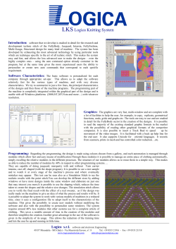


© Copyright 2026