
XMT Toolchain Manual for XMTC Language, XMTC Compiler,
XMT Toolchain Manual for
XMTC Language, XMTC Compiler,
XMT Simulator and Paraleap XMT FPGA Computer
1st version: Aydin O. Balkan, Uzi Vishkin
later versions: George C. Caragea and Alexandros Tzannes
Version 0.82.1
March 18th, 2014
Contents
I
Introduction
4
1 The Purpose of this Manual
5
II
7
XMTC language
2 New Statements of XMTC
2.1 spawn . . . . . . . . . . . . . . . . . . . . . . . . .
2.1.1 Usage . . . . . . . . . . . . . . . . . . . . .
2.1.2 Requirements and Restrictions . . . . . . .
2.1.3 Register spills in XMTC Spawn Blocks . . .
2.1.4 Examples . . . . . . . . . . . . . . . . . . .
2.2 Single Spawn (sspawn) . . . . . . . . . . . . . . . .
2.2.1 Usage . . . . . . . . . . . . . . . . . . . . .
2.2.2 Requirements and Restrictions . . . . . . .
2.2.3 Warnings . . . . . . . . . . . . . . . . . . .
2.2.4 Examples . . . . . . . . . . . . . . . . . . .
2.3 Prefix Sum (ps), and Prefix Sum to Memory (psm)
2.3.1 Usage . . . . . . . . . . . . . . . . . . . . .
2.3.2 Requirements and Restrictions . . . . . . .
2.3.3 Warnings . . . . . . . . . . . . . . . . . . .
.
.
.
.
.
.
.
.
.
.
.
.
.
.
.
.
.
.
.
.
.
.
.
.
.
.
.
.
.
.
.
.
.
.
.
.
.
.
.
.
.
.
.
.
.
.
.
.
.
.
.
.
.
.
.
.
.
.
.
.
.
.
.
.
.
.
.
.
.
.
.
.
.
.
.
.
.
.
.
.
.
.
.
.
.
.
.
.
.
.
.
.
.
.
.
.
.
.
.
.
.
.
.
.
.
.
.
.
.
.
.
.
.
.
.
.
.
.
.
.
.
.
.
.
.
.
.
.
.
.
.
.
.
.
.
.
.
.
.
.
.
.
.
.
.
.
.
.
.
.
.
.
.
.
.
.
.
.
.
.
.
.
.
.
.
.
.
.
.
.
.
.
.
.
.
.
.
.
.
.
.
.
.
.
.
.
.
.
.
.
.
.
.
.
.
.
.
.
.
.
.
.
.
.
.
.
.
.
.
.
.
.
.
.
.
.
.
.
.
.
.
.
.
.
.
.
.
.
.
.
.
.
.
.
.
.
.
.
.
.
.
.
.
.
.
.
.
.
.
.
.
.
.
.
.
.
.
.
.
.
.
.
.
.
.
.
8
8
8
8
9
11
13
13
13
13
14
16
16
16
16
3 Variables
3.1 Local and Global Variables of XMTC
3.1.1 Requirements and Restrictions
3.2 New types of variables . . . . . . . . .
3.2.1 Requirements and Restrictions
.
.
.
.
.
.
.
.
.
.
.
.
.
.
.
.
.
.
.
.
.
.
.
.
.
.
.
.
.
.
.
.
.
.
.
.
.
.
.
.
.
.
.
.
.
.
.
.
.
.
.
.
.
.
.
.
.
.
.
.
.
.
.
.
.
.
.
.
.
.
.
.
.
.
.
.
.
.
.
.
.
.
.
.
.
.
.
.
.
.
.
.
.
.
.
.
.
.
.
.
.
.
.
.
17
17
18
18
18
4 Functions and System Calls
4.1 User Defined Functions . . . . .
4.2 System Calls . . . . . . . . . . .
4.3 Available Input/Output Methods
4.3.1 Data Input . . . . . . . .
4.3.2 Data Output . . . . . . .
.
.
.
.
.
.
.
.
.
.
.
.
.
.
.
.
.
.
.
.
.
.
.
.
.
.
.
.
.
.
.
.
.
.
.
.
.
.
.
.
.
.
.
.
.
.
.
.
.
.
.
.
.
.
.
.
.
.
.
.
.
.
.
.
.
.
.
.
.
.
.
.
.
.
.
.
.
.
.
.
.
.
.
.
.
.
.
.
.
.
.
.
.
.
.
.
.
.
.
.
.
.
.
.
.
.
.
.
.
.
.
.
.
.
.
.
.
.
.
.
.
.
.
.
.
.
.
.
.
.
20
20
20
20
20
20
.
.
.
.
.
.
.
.
.
.
.
.
.
.
.
5 Limitation Summary
22
1
III
Simulation & Execution
23
6 External Datasets and Memory Allocation
6.1 Overview . . . . . . . . . . . . . . . . . . .
6.2 Identifying Data Structures . . . . . . . . .
6.2.1 External Data . . . . . . . . . . . .
6.2.2 Static Memory Allocation . . . . . .
6.3 Using the Memory Tool memMapCreate . . .
6.3.1 Introduction . . . . . . . . . . . . .
6.3.2 Main Menu . . . . . . . . . . . . . .
6.3.3 Set File Names Menu . . . . . . . .
6.3.4 Read / Write Files Menu . . . . . .
6.3.5 Using Input Files . . . . . . . . . . .
6.3.6 Known Bugs . . . . . . . . . . . . .
6.4 Using the Generated Header File . . . . . .
.
.
.
.
.
.
.
.
.
.
.
.
.
.
.
.
.
.
.
.
.
.
.
.
.
.
.
.
.
.
.
.
.
.
.
.
.
.
.
.
.
.
.
.
.
.
.
.
.
.
.
.
.
.
.
.
.
.
.
.
.
.
.
.
.
.
.
.
.
.
.
.
.
.
.
.
.
.
.
.
.
.
.
.
.
.
.
.
.
.
.
.
.
.
.
.
.
.
.
.
.
.
.
.
.
.
.
.
.
.
.
.
.
.
.
.
.
.
.
.
.
.
.
.
.
.
.
.
.
.
.
.
.
.
.
.
.
.
.
.
.
.
.
.
.
.
.
.
.
.
.
.
.
.
.
.
.
.
.
.
.
.
.
.
.
.
.
.
.
.
.
.
.
.
.
.
.
.
.
.
7 Testing the XMTC Program Before Parallel Execution: Using the
7.1 XMTC Serializer . . . . . . . . . . . . . . . . . . . . . . . . . . . . . .
7.1.1 Introduction . . . . . . . . . . . . . . . . . . . . . . . . . . . .
7.1.2 Motivation . . . . . . . . . . . . . . . . . . . . . . . . . . . . .
7.1.3 Assumptions and Restrictions . . . . . . . . . . . . . . . . . . .
7.1.4 XMTC Serializer . . . . . . . . . . . . . . . . . . . . . . . . . .
7.1.5 Walkthrough . . . . . . . . . . . . . . . . . . . . . . . . . . . .
7.1.6 Options . . . . . . . . . . . . . . . . . . . . . . . . . . . . . . .
7.1.7 Contact for Support in XMTC Serializer . . . . . . . . . . . . .
.
.
.
.
.
.
.
.
.
.
.
.
.
.
.
.
.
.
.
.
.
.
.
.
.
.
.
.
.
.
.
.
.
.
.
.
.
.
.
.
.
.
.
.
.
.
.
.
XMT
. . . .
. . . .
. . . .
. . . .
. . . .
. . . .
. . . .
. . . .
.
.
.
.
.
.
.
.
.
.
.
.
.
.
.
.
.
.
.
.
.
.
.
.
.
.
.
.
.
.
.
.
.
.
.
.
.
.
.
.
.
.
.
.
.
.
.
.
24
24
25
25
25
25
25
26
26
28
31
32
32
Serializer 34
. . . . 34
. . . . 34
. . . . 34
. . . . 34
. . . . 35
. . . . 35
. . . . 35
. . . . 36
8 Translating XMTC to OpenMP for Execution on
8.1 XMTC-To-OpenMP Translation Tool . . . . . . .
8.1.1 Introduction . . . . . . . . . . . . . . . . .
8.1.2 Motivation . . . . . . . . . . . . . . . . . .
8.1.3 Assumptions and Restrictions . . . . . . . .
8.1.4 XMTC-To-OpenMP Translation Tool . . .
8.1.5 Walkthrough . . . . . . . . . . . . . . . . .
8.1.6 Options . . . . . . . . . . . . . . . . . . . .
8.1.7 Contact for Support in XMTC Serializer . .
Multi-core Platforms
. . . . . . . . . . . . . . .
. . . . . . . . . . . . . . .
. . . . . . . . . . . . . . .
. . . . . . . . . . . . . . .
. . . . . . . . . . . . . . .
. . . . . . . . . . . . . . .
. . . . . . . . . . . . . . .
. . . . . . . . . . . . . . .
.
.
.
.
.
.
.
.
.
.
.
.
.
.
.
.
.
.
.
.
.
.
.
.
.
.
.
.
.
.
.
.
37
37
37
37
37
38
38
39
39
9 Compiling and Simulating an XMTC Program
9.1 Overview . . . . . . . . . . . . . . . . . . . . . .
9.2 Inclusion of data.h . . . . . . . . . . . . . . . . .
9.3 Compilation of the XMTC Code . . . . . . . . .
9.4 Simulation of XMT Assembly Code . . . . . . . .
9.5 Loading Data into XMT Simulator . . . . . . . .
.
.
.
.
.
.
.
.
.
.
.
.
.
.
.
.
.
.
.
.
.
.
.
.
.
.
.
.
.
.
.
.
.
.
.
.
.
.
.
.
.
.
.
.
.
.
.
.
.
.
.
.
.
.
.
.
.
.
.
.
.
.
.
.
.
.
.
.
.
.
.
.
.
.
.
.
.
.
.
.
.
.
.
.
.
.
.
.
.
.
.
.
.
.
.
.
.
.
.
.
40
40
41
41
43
44
10 Compiling and Executing an XMTC program
10.1 Inclusion of Memory Map . . . . . . . . . . . .
10.2 Compilation of the XMTC Code . . . . . . . .
10.3 Execution on the FPGA: xmtfpga . . . . . . .
10.3.1 xmtfpga . . . . . . . . . . . . . . . . . .
10.3.2 xmtfpgadb . . . . . . . . . . . . . . . .
.
.
.
.
.
.
.
.
.
.
.
.
.
.
.
.
.
.
.
.
.
.
.
.
.
.
.
.
.
.
.
.
.
.
.
.
.
.
.
.
.
.
.
.
.
.
.
.
.
.
.
.
.
.
.
.
.
.
.
.
.
.
.
.
.
.
.
.
.
.
.
.
.
.
.
.
.
.
.
.
.
.
.
.
.
.
.
.
.
.
.
.
.
.
.
.
.
.
.
.
45
45
45
45
46
47
2
.
.
.
.
.
10.4 Loading Data into the FPGA . . . . . . . . . . .
10.5 Getting back the results from the FPGA . . . . .
10.5.1 Retrieving older results from the database
10.6 Examining Memory Contents . . . . . . . . . . .
10.7 Example: A usual work cycle . . . . . . . . . . .
IV
.
.
.
.
.
.
.
.
.
.
.
.
.
.
.
.
.
.
.
.
.
.
.
.
.
.
.
.
.
.
.
.
.
.
.
.
.
.
.
.
.
.
.
.
.
.
.
.
.
.
.
.
.
.
.
.
.
.
.
.
.
.
.
.
.
.
.
.
.
.
.
.
.
.
.
.
.
.
.
.
.
.
.
.
.
.
.
.
.
.
.
.
.
.
.
Warning and Error Messages
48
48
48
49
50
51
11 Error Messages
11.1 Simulator Error Messages . . . . . . . . . . . . . .
11.1.1 General Errors . . . . . . . . . . . . . . . .
11.1.2 File Input/Output Errors . . . . . . . . . .
11.1.3 Errors Related to Use of Arguments . . . .
11.1.4 Runtime Errors . . . . . . . . . . . . . . . .
11.1.5 Errors Related to Assembly File Parsing . .
11.1.6 Errors Related to Assembly File Simulation
V
.
.
.
.
.
.
.
.
.
.
.
.
.
.
.
.
.
.
.
.
.
.
.
.
.
.
.
.
.
.
.
.
.
.
.
.
.
.
.
.
.
.
.
.
.
.
.
.
.
.
.
.
.
.
.
.
.
.
.
.
.
.
.
.
.
.
.
.
.
.
.
.
.
.
.
.
.
.
.
.
.
.
.
.
.
.
.
.
.
.
.
.
.
.
.
.
.
.
.
.
.
.
.
.
.
.
.
.
.
.
.
.
.
.
.
.
.
.
.
.
.
.
.
.
.
.
.
.
.
.
.
.
.
.
.
.
.
.
Glossary
52
52
52
52
53
57
57
58
59
12 Legend and Index
12.1 Legend . . . . . . . . . . . . . . . . . . . . . . . . . . . . . . . . . . . . . . . . . . . .
12.2 Index . . . . . . . . . . . . . . . . . . . . . . . . . . . . . . . . . . . . . . . . . . . .
3
60
60
60
Part I
Introduction
4
Chapter 1
The Purpose of this Manual
Explicit Multi-Threading (XMT) is a computing framework developed at the University of Maryland as part of a PRAM-on-chip vision (http://www.umiacs.umd.edu/~vishkin/XMT). Much in
the same way that performance programming of standard computers relies on C language, XMT
performance programming is done using an extension of C called XMTC.
The above mentioned web site provides a list of publications for readers interested in XMT
Project. Two of these papers summarizes earlier research results and the first generation of the
XMTC programming paradigm:
• U. Vishkin, S. Dascal, E. Berkovich and J. Nuzman. Explicit Multi-Threading (XMT) Bridging
Models for Instruction Parallelism (Extended Summary and Working Document). Current
version of UMIACS TR-98-05. First version: January 1998. (47 pages)
• D. Naishlos, J. Nuzman, C-W. Tseng, and U. Vishkin. Towards a First Vertical Prototyping
of an Extremely Fine-Grained Parallel Programming Approach. TOCS 36, 5 pages 521-552,
Springer-Verlag, 2003. (26 pages)
This manual presents the second generation of XMTC programming paradigm. It is intended to
be used by an application programmer, who is new to XMTC. In this Manual we define and describe
key concepts, list the limitations and restrictions, and give examples. The other related document,
the tutorial, demonstrates the basic programming concepts of XMTC language with examples and
exercises.
Currently, there is an FPGA prototype of XMT and a cycle accurate simulator on which the
programs can execute. This manual also explains how to use XMTC, given the current limitations
of the compiler and simulator. In addition to the compiler and the simulator, our tool chain also
includes a memory map creator to use with external data sets and a serializer for debugging.
Organization We divided this document into 5 parts. The following is a brief overview of the
manual.
Part I
Introduction
Chapter 1 presents the purpose of this manual.
5
Part II XMTC Language
Chapter 2 introduces new XMTC statements and explains their usage.
Chapter 3 describes new XMTC variable types.
Chapter 4 provides important information about function calls and available I/O methods.
Part III Simulation
Chapter 6 explains how to use the memory map creator for external datasets and memory
allocation.
Chapter 7 explains how to use the serializer to test the program before running it with the
simulator.
Chapter 9 explains how to use the compiler and simulator to compile and simulate the XMTC
code.
Part IV Error and Warning Messages: This part lists and explains the warning and error messages
that the compiler and the simulator may produce.
Part V
Glossary
Chapter 12 shows the legend, and explains the XMTC related terms that we used in this manual.
Compatibility This document lists the features of XMT Tool Chain Version 0.82.1 as of March
18th, 2014. While later versions are expected to be backwards compatible, there might be small
changes. For up-to-date information on such changes, please consult the XMTC web page.
Related Documents The XMTC Tutorial focuses on programming examples using XMTC language. The most up-to-date version of these documents can be accessed at
http://www.umiacs.umd.edu/users/vishkin/XMT web site.
History The initial version of this document is completed on February 2005. Based on the improvements in the XMT Toolchain, some sections have been revised on May 2005, February 2006,
January 2007 and March 2008.
Acknowledgments We would like to thank the current members of XMT Research Team for the
contributions to the content of this manual, and their valuable comments.
Contact Person George Caragea: [email protected]
XMTC Web Page
http://www.umiacs.umd.edu/~vishkin/XMT/
6
Part II
XMTC language
7
Chapter 2
New Statements of XMTC
The XMTC language is a superset of the C programming language. Ideally, a serial program written
in pure C would compile and run through the tool chain without any problems. This however is not
the case due to limitations of the tools explained in this document. This chapter summarizes the
new statements of XMTC language that allow parallel programming in a PRAM-like style.
2.1
spawn
2.1.1
Usage
spawn(start_thread, end_thread)
{
// Spawn Block : insert parallel thread code here
}
This statement spawns end thread − start thread + 1 virtual threads, which concurrently and
independently execute the code block following the instruction. The threads assume the ID numbers
within the inclusive interval [start thread; end thread]. In the Spawn Block the Thread ID can be
accessed using the symbol $. If start thread is larger than end thread the Spawn Block will not be
executed.
The XMT processor is said to be in Parallel Mode during the execution of the Spawn Block.
2.1.2
Requirements and Restrictions
1. Parameters: Both of the parameters start thread and end thread must be integer expressions.
2. Variable Declaration: New variables that are used within the spawn block can be declared
at the top of the spawn block. Such variables will be private to each Virtual Thread, i.e. their
values may vary from one Virtual Thread to another Virtual Thread.
3. Thread IDs: The first spawned thread will assume the value of start thread as the thread
ID, the last thread will assume the value of end thread as thread ID (start and end IDs are
inclusive).
8
4. Function Calls: Function calls (both system and user functions) are not allowed from within
the Spawn Block 1 . Currently the compiler will not produce an error or a warning if a function
is called in a spawn block but the program will hang or crash during execution.
5. Access to Variables: All variables declared within the spawn block are fully accessible,
i.e. they can be read or modified freely. Variables declared with type psBaseReg can not be
accessed within a spawn block directly. They must be read or modified through a ps statement.
Variables declared in the enclosing scope of the spawn statement are visible in the spawn block
(i.e. parallel code). While reading them can be done without worries, writing to such a variable
must be done with caution to avoid concurrent writes (see next item) since it is shared by all
parallel threads.
6. Concurrent Writes: Concurrent writes can occurr when more than one thread write to a
memory location (e.g. a shared variable declared in the enclosing scope) within a Spawn Block,
and are not checked by the compiler. Such situations may result in incorrect execution. The
user must be aware of possible concurrent write situations and avoid them (Example 2).
7. Pointers: Pointer arithmetic within the Spawn Block has not been tested and is discouraged.
This is not checked by the compiler. The above restriction does not apply to regular array
accesses (i.e., expressions of the form A[x], where A is an array and x is an expression evaluating
to an integer, are perfectly acceptable).
8. Nesting: If nested spawns are encountered, the inner ones are silently serialized by the compiler (i.e. transformed into for loops)2 . In order to spawn more threads from within the Spawn
Block (during parallel mode), use the sspawn statement.
9. Number of Instructions: If the number of (assembly) instructions within the Spawn Block
exceeds 1000, the compiler will issue a warning and continue compilation. Assuming that
everything else is correct, your program will compile and simulate regardless of instruction
count. However, your results may not be correct. If you see such a warning your parallel code
(Spawn Block ) needs to be split into two or more consecutive spawn statements.
10. Amount of local Storage Available to parallel threads: Currently there is a limitation
to the amount of local storage that parallel threads may use. Local storage consists of variables
(scalars or arrays) that are declared in the Spawn Block. Read the following section on register
spills for more information.
2.1.3
Register spills in XMTC Spawn Blocks
The following restriction applies when programming in XMTC at this time.
Currently the only local storage available to threads is in the TCU registers. Therefore, when
programming in XMTC, special care has to be taken not to overflow the capacity of this storage.
Registers are used to store local variables and temporary values. The compiler does a series of
optimizations to fit everything into registers, but in some cases when a parallel section is long and
complex, it fails to do so and additional storage is required.
At the present time, if the compiler detects such a situation, compilation will fail with the error
message: "Register spill detected in spawn block. Aborting compilation."
1 This
2 This
restriction will be lifted in the next version of the compiler.
restriction will be lifted in the next version of the compiler.
9
The solution is to split the spawn block into shorter, simpler parallel sections for which the
registers provide enough storage. At the present time, if you get an error message from the compiler
regarding register spills, you will have to change the code by splitting the spawn sections yourself.
There is no general recipe for this, you will have to use your knowledge of the application to chose
how to change the code.
Here is a simple example. In the code in the left column below, the value x is used at the
beginning and the end of the tread, but not in the middle. However, this usually requires a register
to be allocated to x and reserved throughout the whole parallel section. This increases the register
pressure and might lead to a register spill, if the code1 and code2 sections are complex and require
using local registers as well.
An immediate possible solution is presented in the righthand column below: the parallel
section is split into two, and x is re-assigned closer to the end, thus reducing the register pressure
and possibly avoiding a register spill.
Initial code
High register pressure
Transformed code
Register pressure is lower
spawn(low, high) {
int i, x = A[$];
for (i=0; i<5; i++) {
B[$+i] = x;
// .. code 1 .. //
}
for (i=0;i<5;i++) {
// .. code 2 .. //
}
C[$] = x;
}
spawn(low, high) {
int i, x = A[$];
for (i=0; i<5; i++) {
B[$+i] = x;
// .. code 1 .. //
}
} // join
spawn(low,high) {
int i, x;
for (i=0;i<5;i++) {
// .. code 2 .. //
}
x = A[$];
C[$] = x;
} // join
A medium-term solution, which is currently under development, is to use a parallel stack,
stored in shared memory. However, there is a performance issue with this solution: storing and
retrieving values from shared memory is much slower than the registers, and can significantly affect
running time of the parallel section (for example if the memory access occurs in a loop).
The long term ideal solution will include the following ingredients:
• increasing the number of registers available
• adding some type of local memory to the TCUs (e.g. cluster buffers or scratch-pads) and
retargetting register spills to them (instead of shared memory)
• have the compiler perform spawn block splitting (as showed above) to minimize using the stack
and generate the optimal code without the programmer’s assistance
• use data prefetching mechanisms to reduce the penalty of a register spill to memory.
10
2.1.4
Examples
Example-1
An example of legal spawn usage
In the following code we spawn virtual thread s with thread IDs ranging from 0 to N − 1. Then
we create an integer variable temp. Each virtual thread has its own copy of this variable. We
read the array C using an expression containing the $ character. Based on this value, we copy
an element from B array to A array either as it is, or the negative of it.
int main()
{
...
int N;
...
spawn(0, N-1);
{
int temp;
temp = C[$*2];
if(temp > 0) {
A[$]=B[$];
} else {
A[$]=-B[$];
}
}
...
Example-2
Writing some value to a variable by multiple virtual threads
According to Arbitrary-CRCW PRAM model, if multiple threads attempt to write to a memory
location, an arbitrary one of them will succeed. This arbitration needs to be handled by the
programmer. Otherwise the outcome of the program may be undetermined.
For consistency, prefix-sum statements (ps or psm) must be used to execute concurrent writes
These statements act as gatekeepers that allow only one of the writers to go through. See
Section 2.3 for more details on these statements.
In the code on the left, j = temp assignment is a concurrent-write operation. In this case,
different threads may write different values to j in some arbitrary order. The order of writing
may depend on both hardware and software components and it is not predictable. The final
value of j and the identity of the modifying thread can not be determined after the spawn
block.
In the code on the right, the j = temp assignment is encapsulated by a gatekeeper operation.
The atomic ps operation ensures that only one thread gets permission to modify j. In this case
both the value and the identity of the modifying thread can be determined after the spawn
block.
11
Incorrect handling of variable j:
Correct handling of variable j:
int j; // j is a global variable
psBaseReg gateKeeper;
int main()
{
// Beginning of a serial block
int j;
int main()
{
//Beginning of a serial block
// Some Serial Code
spawn(low, high)
{
// Some Serial Code
gateKeeper = 0;
int temp;
spawn(low, high)
{
int i;
int temp;
...
i=1;
ps(i,gateKeeper);
...
temp = ...
...
j = temp;
// Only one thread will get
// 0 from ps instruction
if(i == 0) {
j = temp;
}
...
}
// Rest of the Program
}
...
}
// Rest of the Program
}
12
2.2
2.2.1
Single Spawn (sspawn)
Usage
spawn(low, high)
{
int child_ID;
// Some parallel code here
sspawn(child_ID)
{
// Initialization Block:
// Code for initializing the child thread
}
// Some other parallel code here
}
With this statement, the current thread (parent thread ) spawns a single virtual thread (child
thread ). The parent thread executes the code in the initialization block that follows the statement,
and the child thread starts from the first line of parent’s spawn block. This causes a race condition
since the child thread might start executing before the parent has finished initializing its children
and proper synchronization must be provided by the programmer (see requirement 4). The thread
ID of the newly spawned thread is copied to the parameter of the sspawn (child ID). This value
can be read from within the initialization block. The value of the child ID is the next available
thread ID. This means that if you spawn 10 threads with thread IDs ranging from 0 to 9 and spawn
one additinal thread using sspawn its thread ID will be 10.
2.2.2
Requirements and Restrictions
1. Parameter: The parameter must be an integer declared within the parent’s spawn block.
Constant numbers and mathematical operators cannot be used as a part of the parameter.
2. Thread ID: Within the initialization block the character $ still refers to the thread ID of the
parent thread.
3. New Variables: In an initialization block new variables may not be declared.
4. Synchronization: In order to prevent premature starting of child threads, a synchronization
mechanism must be used (Example 4).
2.2.3
Warnings
1. Every time the sspawn statement is encountered, one more thread will be spawned. Since
this new thread executes the same spawn block, it may encounter the sspawn statement at
some point during the execution. This feature allows recently spawned threads to spawn more
threads, as opposed to limiting the spawning ability to the original set of threads. On the
other hand, if sspawn is not used correctly, an infinite number of threads might be spawned.
Therefore, this statement should be used with caution, and preferably enclosed within a control
structure such as if or while (or others) (Example 3).
13
2. The value in child ID prior to the execution of this statement will be overwritten.
2.2.4
Examples
Example-3
Avoiding infinite spawns
The following example shows a method of avoiding infinite spawns. Please note that the
method shown in this example may not be the most efficient one in terms of program performance. In order to reduce complexity, the synchronization statements are not shown in the
below program
Uncontrolled sspawn leads to infinitely
many threads (and eventually, crashing)
Controlled sspawn statement spawns as
many threads as needed
int N; // Total amount of work
int M; // Initial thread count
// N >> M
int N; // Total amount of work
int M; // Initial thread count
// N >> M
int main()
{
// Beginning of a serial block
// Some Serial Code
spawn(0, M-1)
{
int childID;
int main()
{
// Beginning of a serial block
// Some Serial Code
spawn(0, M-1) {
int child_ID;
int my_workload;
if($<M) {
my_workload=N/M;
} else {
my_ workload=1;
}
sspawn(childID)
{
// Initialize child here
}
if( $ < N )
{
// do some work
}
while(my_workload>1) {
sspawn(child_ID) {
// Initialize child here
}
my_workload--;
}
// do some work
}
// Rest of the Program
}
}
// Rest of the Program
}
Example-4
Synchronization for sspawn statement
The following example uses integer variables as locks (or semaphores) to prevent the child
thread from starting before its initialization is completed.
14
int locks[100];
...
int main()
{
...
spawn(low,high)
{
int child_ID;
int lock;
if (thread is a single-spawned thread) {
lock=0;
while (lock==0) {
// spin-wait
psm(lock,locks[$]); // read the lock
}
}
...
sspawn(child_ID)
{
... Initialization Block: Code for newly spawned thread
lock=1;
psm(lock,locks[child_ID]); // give signal to child
}
... Some other parallel code here ...
}
... Some other serial code here ...
}
15
2.3
2.3.1
Prefix Sum (ps), and Prefix Sum to Memory (psm)
Usage
ps(int local_integer, psBaseReg ps_base);
psm(int local_integer, int variable);
Both statements execute the following operations atomically:
• Add the value of the local integer to the second parameter (ps base for ps, memory location
for psm).
• Copy the old value of the second parameter to the local integer
2.3.2
Requirements and Restrictions
1. Parameters: local integer must be declared as int within the current Spawn Block .
Parameter ps base must be declared as psBaseReg at global scope. Parameter variable
must be an integer variable (it can be an element of an array of integers). See Chapter 3 for
details. Also note that, constant numbers and mathematical operators cannot be used as a
part of these parameters.
2. Value Restriction for ps: For the ps statement the value of local integer must be equal
to 0 or 1 prior to the execution. This restriction comes from the implementation of the XMT
architecture. There is no such restriction for the psm statement.
3. Number of prefix-sum base registers: Due to architectural constraints, the user can only
declare 6 variables of type psBaseReg for use with the ps statement. In future versions, this
restriction may be relaxed.
2.3.3
Warnings
1. Performance: The performance minded programmer should prefer the ps statement over
the psm statement, whenever possible. The XMT architecture provides a more performanceefficient execution for the ps statement. ps statements from different threads on the same
psBaseReg variable are executed concurrently, while psm statements from different threads
on the same memory location will be serialized (which could cause queueing). In terms of
performance, this feature is analogous to working on a variable in architectural registers as
opposed to working on the same variable in main memory without loading it into registers.
16
Chapter 3
Variables
3.1
Local and Global Variables of XMTC
XMTC adheres to the global variable definition of the C language: A global variable can be accessed
from every point in the code. In other words, global variables are shared among parallel threads.
We will examine local variables in two groups:
1. C-like local variables: Variables in this group are treated the same as in C language. A local
variable can only be accessed from within the scope that it is declared (e.g. a function block).
This includes parallel threads created in the scope of the local variable.
2. Thread-local variables declared within a spawn block : Such variables are private to each virtual
thread. In other words, each virtual thread has its own copy of that variable.The first parameters of ps and psm statements as well as the parameter of sspawn statement must be integers
of this type. They must be declared at the beginning of the Spawn Block.
ATTENTION: Thread-local variables are often a source of confusion for beginner programmers
in XMTC. If you are computing some expression in a parallel thread and you want to store an
intermediate result in a temporary variable, storing it in a shared variable may cause its value to
be overwritten by another thread (as is done below on the left). A better approach is to declare the
temporary variable in the spawn block we are working and use that one (as is done below on the
right).
int main(void)
int temp;
int A[10];
int B[10];
int C[10];
spawn(0,9)
temp =
C[$] =
}
...
return 0;
}
{
// initialized
// initialized
{
A[$];
B[temp];
int main(void) {
int A[10]; // initialized
int B[10]; // initialized
int C[10];
spawn(0,9) {
int temp;
temp = A[$];
C[$] = B[temp];
}
...
return 0;
}
Currently, XMTC allows the use of following types of variables:
17
• integer (int and long) both of 32 bit size1
• above types with const and static modifiers. Note that volatile is not supported and is
not currently checked by the compiler (so if you use it you will get no warning).
• arrays of above types.
• structs, and arrays of structs containing above types
• pointers to the above types.
union, and enum keywords are also allowed in variable declarations. Their usage is the same as
in C language.
3.1.1
Requirements and Restrictions
1. global variables cannot be initialized upon declaration. They must be initialized inside a
function body (such as main() for example).
2. Variable names must not contain the character $.
3. unsigned is not supported.
Local Variables within Spawn Block
1. The local variables that are declared within the spawn block are stored in the architectural
registers of the TCU. Since there are a limited number of hardware resources to be used as
for this purpose, the programmer should be conservative in declaring such variables. If the
compiler needs more registers than are available in parallel mode, it will warn the user to be
more conservative with declaring thread local variables.
2. New variables may not be declared within the Initialization Block after sspawn instruction.
3.2
New types of variables
psBaseReg Variables of this type are base variables for the prefix-sum statement. A ps statement
must use a variable of this type as the second parameter.
3.2.1
Requirements and Restrictions
psBaseReg
1. Declaration: These variable must be declared at global scope, before any functions are
declared or defined (including main()).
2. Initialization: Variables of type psBaseReg cannot be initialized upon declaration. It is
recommended you initialize them in the code of some function (such as main() for example).
1 Single/double precision floating point (float and double) are also allowed but have not been tested extensively.
The simulator permits both float and double. The Paraleap FPGA does not support floating point, but a newer
prototype does (float only).
18
3. Variable Access: Variables of type psBaseReg are accessible (can be read/written) normally
from the serial section. From the parallel sections they can be accessed only by ps statements.
4. Number of psBaseReg variables: Due to architectural limitations, at most 6 variables of
this type can be declared in a program. In the future versions this limitation may be relaxed.
19
Chapter 4
Functions and System Calls
Function calls of any kind are not allowed in the Spawn Block. If function calls are used the compiler
will not produce any warning or error, but the execution will fail. This limitation is the first for
removal on our roadmap.
4.1
User Defined Functions
XMTC supports user defined functions. Programmers can write functions following the rules and
constraints of the C language.
4.2
System Calls
Currently, the XMTC architecture does not have support for calls to the operating system. In
the future, XMTC will support frequently used libraries, such as I/O operations and math library.
Currently, programmer must refrain from using system calls and libraries.
4.3
4.3.1
Available Input/Output Methods
Data Input
The programmers can use the Memory Tool (see Chapter 6) in order to prepare their external data
to use with the simulator or the XMT FPGA computer.
4.3.2
Data Output
printf Statement
This functionality is available both on the java simulator and the FPGA. The programmers must
include the xmtio.h library headers and can use the printf function in order to print program results
to the terminal window (standard output or stdout). The usage of the printf statement is similar,
yet not identical, to the printf function of the stdio system library.
20
Requirements and Restrictions
1. Do not use #include <stdio.h> in your programs. The I/O library is automatically linked
by the compiler.
2. Since the only valid data type is int, only the %d format specifier can be used (%s, %f, etc.
are not supported). 1
3. The format string supports only basic format characters. Width modifying strings such as
“%02d” are not supported.
4. Even though char and char* types are not supported, printing of constant strings is supported.
Examples: printf(’’hello world’’);, printf(’’hello world %d’’, x);
5. On the Paraleap XMT FPGA computer, there is a limit on the number of characters that
are printed. Currently, the program standard output (produced using printf statements) is
truncated after the first 114,687 characters. See section 10.6 for a method of testing programs
that exceed this limit.
1 The
XMT Cycle-Accurate simulator has support for printing double variables using the %f format specifier.
21
Chapter 5
Limitation Summary
XMTC extends ANSI C (also known as C89) and therefore the extensions found in C99 are not
supported, or at least not fully supported yet. Here is the full list of limitations:
• Variable length arrays are not supported.1
• Function pointers are not fully supported (use at your own risk).
• Pointer arithmetic within spawn statements is discouraged.
• The number of assembly instructions resulting from the compilation of a spawn block cannot
exceed 1000. If that happens the compiler will issue a warning and continue when compiling
for the simulator, or produce an error and abort when compiling for the FPGA.
• If spawn statements are nested the current compiler will replace inner spawn statements by
(sequential) for-loops.2
• Function calls are not allowed within spawn statements (yet).3
• psBaseReg variables cannot be used in parallel mode, except through the ps statement.
• The number of local variables declared in spawn statements must be small enough to fit in the
registers of the parallel Thread Control Unit (TCU). If the compiler cannot register allocate
all local variables it will abort with a “register spill” error.
• The ps statement can only be used in parallel mode. Its first argument must have a value of
either 1 or 0, and its second argument must be a variable declared as psBaseReg.
• psBaseReg variables must be declared at global scope but cannot be initialized at global scope,
only within a function.
• You can declare at most 6 variables of type psBaseReg.
• When using the Paraleap XMT FPGA computer to execute XMTC programs, the standard
output is truncated after printing 114,687 characters. See section 10.6 for a method of testing
programs that exceed this limitation.
1 The
next version of the compiler will support stack-allocated arrays of variable length.
restriction will be lifted in the next version of the compiler.
3 This restriction will be lifted in the next version of the compiler.
2 This
22
Part III
Simulation & Execution
23
Chapter 6
External Datasets and Memory
Allocation
6.1
Overview
Currently, XMT FPGA and simulator are not able to handle calls to the operating system. Two
types of frequently used system calls are file operations such as reading the input data from a file,
and dynamic memory allocation. A temporary method has been developed for the users to work
with external data, and allow them to allocate memory statically:
1. The user identifies the data structures present in an XMTC program, and prepares content
files in appropriate format.
2. Using memMapCreate tool (Memory Tool ) with these content files the user prepares
(a) A header file (.h) to be used with the program code (Memory Map - header file)
(b) A binary file (.xbo) to be used as an input to the compiler (Memory Map - binary file)
(c) As a byproduct, the tool also generates a text (.txt) file showing the contents of the
binary file (Memory Map - text file). This file is not being used by the C code nor the
Simulator or FPGA. It may be used for testing or debugging purposes.
3. The header file has to be included (either using #include directive or -include compiler
option) in the program code. (see Section 9.2)
4. The binary file (.xbo) has to be fed to the compiler on the command-line (see Section 9.3)
5. If the simulator is used the binary file produced by the compiler (a.b) has to be loaded using
the -binload option (see Section 9.5). If the FPGA is used, the binary file produced by the
compiler a.b contains both the code and the data, and no additional flags are necessary (see
Section 10.4).
24
6.2
6.2.1
Identifying Data Structures
External Data
The first task of preparing the external input set is identifying the data structures to be used in the
program.
• The user has to initialize the scalar variables, and array variables in the memory.
1 or 2 dimensional arrays of these types can be created as well.
1
Moreover
• For each variable, the user is required to
1. Declare its name
2. Declare its (dimensions and) size
3. Choose the content of each variable among
(a)
(b)
(c)
(d)
0 (for scalar variables)
A fixed value (for scalar variables)
All elements 0 (for arrays)
All elements uniformly random between 0 and 1 for floating point arrays, and between
0 and a user defined upper limit for integer arrays
(e) A text file (content file) containing the value of each element (for arrays)
6.2.2
Static Memory Allocation
The user can use the above method for allocating portions of the memory to be used in the program. The size of these portions needs to be known a priori. Allocation can be made using arrays. For example, 1024 words of memory for integer values can be allocated by creating the array
int temp1024[1024]; using the above method. Later they can be accessed similar to regular arrays.
6.3
6.3.1
Using the Memory Tool memMapCreate
Introduction
This tool is designed to help with creating header and binary files to be used with the XMT toolchain.
In order to navigate within the program enter the number or letter or symbol for the desired action
and hit Enter. Here we are describing Revision 0.8.1 of this tool for XMT (memMapCreate). The
revision number is displayed above the main menu as the program is started.
1 Currently, the XMT FPGA computer does not have support for floating point operations. A newer FPGA
prototype has support for single-precision floating point operations only. We plan to add support for double-precision
in the near future.
25
6.3.2
Main Menu
**************************************************
**************************************************
*
*
*
XMTC Header File Creator
*
*
Revision 0.8.1
*
*
*
*
*
*
M A I N
M E N U
*
*
*
* 1. Set File Names
*
* 2. Read/Write Header and Memory Map
*
* 3. Set Random Number Seed
*
* q. Quit
*
*
*
**************************************************
*** > _
1 Set File Names Takes you to the Set File Names Menu (Section 6.3.3)
2 Read/Write Header and Memory Map Takes you to the Read/Write Files Menu (Section 6.3.4)
3 Set Random Number Seed Displays you the default random number seed, and asks you if
you want to change it. If you answer with y the program asks you for a new seed.
q Quit Quits the program
6.3.3
Set File Names Menu
**************************************************
**************************************************
*
*
*
S E T
F I L E
N A M E S
*
*
*
* 1. Set Header Name
*
* 2. Set Memory Map Name
*
* 3. Set Text file Name
*
* 4. Set common name for all three files instead*
* < Back to previous Menu
*
*
*
**************************************************
*** > _
1 Set Header Name
• Displays the current name for the header file, and asks you for a new one.
• You must type one character at least, before hitting Enter.
26
• The program does not add the file extension .h by itself, you need to type it explicitly.
• You must enter a valid name here before executing R or H commands in the Read/Write
Files Menu (Section 6.3.4)
2 Set Memory Map Name
• Displays the current name for the binary Memory Map file, and asks you for a new
one.
• You must type one character at least, before hitting Enter.
• The program does not add the file extension .xbo by itself, you need to type it explicitly.
• You must enter a valid name here before executing B command in the Read/Write Files
Menu (Section 6.3.4)
3 Set Text File Name
• Displays the current name for the ASCII Memory Map file, and asks you for a new
one.
• You must type one character at least, before hitting Enter.
• The program does not add the file extension .txt by itself, you need to type it explicitly.
• You must enter a valid name here before executing B command in the Read/Write Files
Menu (Section 6.3.4)
4 Set common name for all three files instead
• Asks you for a common name for all three files
• You must type one character at least, before hitting Enter.
• The .h, .xbo, and .txt extensions are added automatically. You only need to type in
the common base name for all three files.
< Back to previous Menu Goes Back to the Main Menu (Section 6.3.2)
27
6.3.4
Read / Write Files Menu
**************************************************
**************************************************
*
*
*
R E A D / W R I T E
F I L E S
*
*
*
* 1. Add Integer Scalar Variable
*
* 2. Add Integer Array Variable
*
* 3. Add Double Scalar Variable
*
* 4. Add Double Array Variable
*
* R. Read Variables from Header File
*
* L. List Current Variables
*
* D. Delete Last Variable
*
* H Create Header File
*
* B Create Text and Binary Files from sources *
* < Back to previous Menu
*
*
*
**************************************************
*** > _
1 Add Integer Scalar Variable
• Asks the name of the scalar variable.
• Confirms the name.
• Asks for the Value. You must enter one digit at least. During creation of the text/binary
file, if the entry is text (not a number), it will be converted to 0. If the entry is a floating
point number, it will be rounded down. (uses atol() function of C).
• Warning: The program does not check for identical variable names. The programmer is
responsible to track the names of the variables.
2 Add Integer Array Variable
• Asks the name of the array variable.
• Asks the dimension of the array variable. Currently you can only create 1 or 2 dimensional
arrays.
• Asks the sizes of each dimension. The size of each dimension will be added as a scalar
variable. For example, for the array called myArray[1024] there will be a scalar integer variable myArray_dim0_size, which has the value 1024. If the array would be
two dimensional, such as array2D[10][20], there will be two scalar integer variables:
array2D_dim0_size with the value 10, and array2D_dim1_size with the value 20.
• Asks for the source. You have 3 options:
(a) <file> : Reads one integer from the content file <file> per element. If the variable
is two-dimensional, the second dimension is read first, i.e. the elements array[0][0]
to array[0][array dim1 size - 1] are read first. The program reads only as many
elements as the array contains (for example, 15 elements for array[3][5]). If the
content file has more elements, they will not be read.
28
(b) 0 : Sets all elements to 0
(c) R : This is for filling the array with random elements. The program asks for the
upper bound. The lower bound is always 0. If the upper bound is entered as 0, the
default value of 106 replaces 0.
• Warning: The program does not check for identical variable names. The programmer is
responsible to track the names of the variables.
3 Add Double Scalar Variable
2
• Asks the name of the scalar variable.
• Confirms the name.
• Asks for the Value. You must enter one digit at least. During creation of the text/binary
file, if the entry is text (not a number), it will be converted to 0. The atof() function of
C standard library is used for conversion.
• Warning: The program does not check for identical variable names. The programmer is
responsible to track the names of the variables.
4 Add Double Array Variable
3
• Asks the name of the array variable.
• Asks the dimension of the array variable. Currently you can only create 1 or 2 dimensional
arrays.
• Asks the sizes of each dimension. The size of each dimension will be added as a scalar
integer variable. For example, for the array called myArray[1024] there will be a scalar
integer variable myArray_dim0_size, which has the value 1024. If the array would be
two dimensional, such as array2D[10][20], there will be two scalar integer variables:
array2D_dim0_size with the value 10, and array2D_dim1_size with the value 20.
• Asks for the source. You have 3 options:
(a) <file> : Reads one double precision floating point number from the content file
<file> per element. If the variable is two-dimensional, the second dimension is read
first, i.e. the elements array[0][0] to array[0][array dim1 size - 1] are read
first. The program reads only as many elements as the array contains (for example,
15 elements for array[3][5]). If the content file has more elements, they will not
be read.
(b) 0 : Sets all elements to 0
(c) R : This is for filling the array with random double precision floating point numbers
between 0 and 1.
• Warning: The program does not check for identical variable names. The programmer is
responsible to track the names of the variables.
R Read Variables from Header File
2 Currently,
the XMT
prototype has support for
in the near future.
3 Currently, the XMT
prototype has support for
in the near future.
FPGA computer does not have support for floating point operations. A newer FPGA
single-precision floating point operations only. We plan to add support for double-precision
FPGA computer does not have support for floating point operations. A newer FPGA
single-precision floating point operations only. We plan to add support for double-precision
29
• Reads the header file with the name declared in Set File Names Menu (Section 6.3.3).
• The header file must be created previously by this program using H command of this
menu. Otherwise the program may not recognize the variables. (Manually modifying the
header file is possible, yet strongly discouraged)
• The read variables are added to current list. If you read the same header file twice,
all variables will appear twice, which may cause the compiler to throw errors because of
duplicate definition.
L List Current Variables
• Lists current variables in the memory that are either read from the header file using R
command, or created using 1, 2, 3 or 4 commands. An example screenshot is below:
*** > L
Name
Dimension
Size [0]
Source
:
:
:
:
gen_array
1
1024
R 10000
Name
Dimension
Size [0]
Source
:
:
:
:
gen_aux_array
1
1024
0
Name
Dimension
Size [0]
Source
:
:
:
:
gen_temp_array
1
1024
0
Name
Dimension
Size [0]
Source
:
:
:
:
gen_pointer
1
1
0
Name
Dimension
Size [0]
Source
:
:
:
:
gen_randomNumbers
1
500
R 65536
D Delete Last Variable
• Deletes the last variable at the end of the list shown by L command.
• This action is not undoable.
H Create Header File
• Creates the header file with the name defined by 1 command in Set File Names Menu.
(Section 6.3.3)
• If there is already a file by that name, it will be overwritten without a notice.
30
• Returns to the Main Menu (Section 6.3.2).
B Create Text and Binary Files from sources
• Creates text and binary files with the names defined by 2 and 3 commands in Set File
Names Menu. (Section 6.3.3)
• If there are already files by these names, they will be overwritten without a notice.
• The files defined as sources of array variables (see 2 command of this menu) must exist.
< Back to previous Menu Goes Back to the Main Menu (Section 6.3.2)
6.3.5
Using Input Files
The keystrokes for generating a particular set of memory files (header and binary files) using the
memMapCreate program can be externally stored in a text file. Such a text file can be fed into the
memMapCreate program using basic redirection operators.
Example-5
Using an input file with the memMapCreate program
The following input file does the followings:
• Set the header file name to myHeader.h
• Set the binary data file name to myData.xbo
• Set the text data file name to myData.txt
• Create an integer scalar variable with name a and value 50
• Create an integer scalar variable with name b and value 100
• Create an integer one-dimensional array with name arr1 and size 500. The contents of
the array will be read from the text file array1.txt.
• Create an integer one-dimensional array with name temp1k1 and size 1024. All elements
of this array will be equal to 0.
• Create header and data files
• Quit memMapCreate
Suppose that this input file is saved with the name inputFile.txt. To use this file with
memMapCreate program, type:
memMapCreate < inputFile.txt
31
Contents of the input file inputFile.txt
1
1
myHeader.h
2
myData.xbo
3
myData.txt
<
2
1
a
y
50
1
b
y
100
2
arr1
1
500
array1.txt
y
2
temp1k1
1
1024
0
y
h
2
b
<
q
6.3.6
Known Bugs
We would appreciate, if you inform us in case you encounter the following bug or new bugs.
1. If the backspace key is used under certain conditions the program will encounter a segmentationfault when writing out the files.
6.4
Using the Generated Header File
The generated header file includes the declaration for all the global variables that must be initiated
in the shared memory before the execution is started, as well as size variables for the array variables.
32
Additionally, the header file may also contain the declaration for the temporary arrays. An example
is below:
extern int degrees[1000];
extern int degrees_dim0_size;
extern int edges[10000][2];
extern int edges_dim0_size;
extern int edges_dim1_size;
Here, the user requested the 1-D array int degrees[1000] and the 2-D array int edges[10000][2]
by using the memMapCreate program described in Section 6.3. The additional scalar variable int
degrees dim0 size has the value 1000, and the variables int edges dim0 size and int edges dim1 size
have the values 10000 and 2 respectively.
The header file must be included during the compilation of the XMTC file either by using the
#include directive similar to including regular C header files, or the -include option of the compiler.
For more details please see Section 9.2.
The exten keyword instructs the compiler not to allocate space for these variables since they are
initialized in the binary .xbo file.
33
Chapter 7
Testing the XMTC Program
Before Parallel Execution: Using
the XMT Serializer
7.1
7.1.1
XMTC Serializer
Introduction
In this section, the terms ’user’ and ’programmer’ refer to the reader. ’XMTC Serializer’ and
’Serializer’ are used interchangeably, and refer to the program that is meant for the user.
7.1.2
Motivation
The XMT toolchain consists of multiple tools that are NOT bug-free. The state of the compiler,
simulator and FPGA make it difficult to test code, since the programmer has no way of knowing
whether they made a mistake or whether the error is caused by the compiler/simulator/FPGA. That
said, the stability of those components is reasonably stable now to allow programmers to directly
try running their code using the compiler and simulator or FPGA, and if the code is not running to
fall back to the techniques presented in this section.
Solution Serialize the the user’s XMTC program so that it can be compiled using a stable, serial
compiler (such as gcc).
7.1.3
Assumptions and Restrictions
The following is a (potentially incomplete) list of known restrictions:
1. If you are using xmt libraries such as xmtio.h, you must provide a counterpart for the serial
code or provide the library code to gcc. In the future this will be provided automatically by
the serializer.
34
7.1.4
XMTC Serializer
The Serializer generates a copy of your code that can be compiled with traditional compilers. GCC
was tested during development.
The Serializer consists of two executables: xmtcser and memReader. The latter is not directly
called by the user however it has to be in a directory that is on the system path.
7.1.5
Walkthrough
1. Assume there exists a program ‘mycode.c’.
To Serialize ‘mycode.c’ for gcc the user executes
xmtcser mycode.c
2. In addition to ‘mycode.c’, assume ‘mydata.xbo’ and ‘mydata.h’ files were generated by the
memory map tool and ‘mydata.h’ is included in ‘mycode.c’.
To Serialize ‘mycode.c’ with memory map for gcc the user executes
xmtcser mycode.c -memload mydata.h mydata.xbo
• The Serializer will generate an output file called mycode.serialized.c. If the memload
option was used as above, the file xmt2OpenMP serialized mydata.h will be generated
as well.
3.
• If the -memload option was used, the Serializer will insert the following line at the top of
’mycode.serialized.c’:
#include "xmt2OpenMP serialized mydata.h"
• The Serializer will insert the initial values for all the global variables defined in the serial
version of the memory header file.
4. At this point the user may compile the generated files using a C compiler. For example, using
GNU GCC:
gcc mycode.serialized.c -o mycode
Include directives in the source C file are automatically converted to the new header filenames
therefore user does not need to make manual changes.
Should any errors occur during compilation, the user should examine the generated files for
obvious errors. For assistance, contact the author of XMTC Serializer (See the Contacts
section).
5. Execute the resulting sequential program just as you would run any executable on your platform:
./mycode
7.1.6
Options
Running xmtcser -h will print the following help:
Usage: xmtcser [OPTIONS] <filename>
35
OPTIONS:
-h, -help
Print usage help
-v, -version
Print the version information
-o, -output
Output file. Default is <filename>.omp.c
-memload <file.h> <file.xbo>
Pre-load data from the file.h and file.xbo
files,
generated using the XMT tools
-include <filename>
Add <filename> to the list of included files
-D
Add a preprocessor #define
-quiet:
Be quiet!
-dirty
Do not delete intermediary files after end of compilation
This section discusses the options in more detail.
1. -memload <file.h> <file.xbo> If the memload option is used the memory map will be read
from files file.h and file.xbo These files should be created using the memory map tool and
should not be edited manually. xmt2OpenMP serialized mydata.h file will be created as the
output.
2. -h
When the ’-h’ option is used, the Serializer prints the help screen and exits without processing
any files.
7.1.7
Contact for Support in XMTC Serializer
Please contact XMT Research Team.
36
Chapter 8
Translating XMTC to OpenMP for
Execution on Multi-core Platforms
8.1
8.1.1
XMTC-To-OpenMP Translation Tool
Introduction
In this section, the terms ’user’ and ’programmer’ refer to the reader. ’XMTC-To-OpenMP Translation Tool’ and ’XMTC2OpenMP’ are used interchangeably, and refer to the program that is meant
for the user.
8.1.2
Motivation
The XMT toolchain includes a vertical development solution, comprising algorithmic model, programming language, optimizing compiler, system tools and libraries and hardware platform.
However, to allow for an easy transition and facilitate adoption, we provide an alternative environment of execution for software written using the XMTC programming language: converting
XMTC programs to OpenMP code. OpenMP1 is a widely adopted programming standard designed
for shared-memory architectures. A variety of OpenMP compilers exist for various architectures and
operating systems.
By allowing programmers to convert code from XMTC to OpenMP, we can ensure that they can
re-use their code if targetting different platforms. At the same time, programmers can take advantage
of the existing parallel architectures, compilers and development environments (such as GNU GCC
with OpenMP support and multi-core architectures) even when using the XMTC programming
language.
Note that the XMT Algorithmic and Programing Model, the XMTC language and compiler and
the XMT architecture have been designed as a unit, and therefore best performance is achieved only
when using them in conjuction. A significant penalty loss might occur by conversion to OpenMP
code and execution on different platforms.
8.1.3
Assumptions and Restrictions
The following is a (potentially incomplete) list of known restrictions:
1 http://openmp.org
37
1. Single-spawn constructs sspawn() are not supported. There is no direct mapping of
the single-spawn semantics onto OpenMP, and therefore programs containing single-spawn
statements cannot be converted. In the future, we will support nested spawn constructs, which
will eliminate the need for single-spawns in XMTC code. Note that the XMTC Serializer
supports single-spawns, and can therefore be used for debugging and running any XMTC
program as sequential code.
2. If you are using xmt libraries such as xmtio.h, you must provide a counterpart for the serial
code or provide the library code to gcc. In the future this will be provided automatically by
the serializer.
8.1.4
XMTC-To-OpenMP Translation Tool
The XMTC2OpenMP tool generates a C program which contains OpenMP directives. This program
can be compiled with any compiler that supports the OpenMP API. We have tested the tool using
GNU GCC 4.1.
The XMTC2OpenMP consists of two executables: xmtc2omp and memReader. The latter is not
directly called by the user however it has to be in a directory that is on the system path.
8.1.5
Walkthrough
1. Assume there exists a program ‘mycode.c’.
To translate ‘mycode.c’ to C + OpenMP code, the user executes
xmtc2omp mycode.c
2. Alternatively, assume that in addition to ‘mycode.c’, ‘mydata.xbo’ and ‘mydata.h’ files were
generated by the memory map tool and ‘mydata.h’ is included in ‘mycode.c’.
To translate ‘mycode.c’ to C + OpenMP code with data initilized using the memory map the
user executes
xmtc2omp mycode.c -memload mydata.h mydata.xbo
3.
• The XMTC2OpenMP tool will generate an output file called mycode.omp.c. If the memload option was used as above, the file xmt2OpenMP serialized mydata.h will be
generated as well.
• If the -memload option was used, the XMTC2OpenMP tool will insert the following line
at the top of ’mycode.omp.c’:
#include "xmt2OpenMP serialized mydata.h"
• The XMTC2OpenMP tool will insert the initial values for all the global variables defined
in the serial version of the memory header file.
4. At this point the user may compile the generated files using an OpenMP-compliant C compiler.
For example, using GNU GCC 4.x (and above):
gcc -fopenmp -I omp.h mycode.omp.c -o mycode
Include directives in the source C file are automatically converted to the new header filenames
therefore user does not need to make manual changes.
Should any errors occur during compilation, the user should examine the generated files for
obvious errors. For assistance, contact the authors of XMTC2OpenMP tool (See the Contacts
section).
38
5. Execute the resulting parallel program just as you would run any executable on your platform:
./mycode
If multiple cores are present on the target platform, the program will execute using all the
available cores.
8.1.6
Options
Running xmtc2omp -h will print the following help:
Usage: xmtc2omp [OPTIONS] <filename>
OPTIONS:
-h, -help
Print usage help
-v, -version
Print the version information
-o, -output
Output file. Default is <filename>.omp.c
-memload <file.h> <file.xbo>
Pre-load data from the file.h and file.xbo
files,
generated using the XMT tools
-include <filename>
Add <filename> to the list of included files
-D
Add a preprocessor #define
-quiet:
Be quiet!
-dirty
Do not delete intermediary files after end of compilation
This section discusses the options in more detail.
1. -memload <file.h> <file.xbo> If the memload option is used the memory map will be read
from files file.h and file.xbo These files should be created using the memory map tool and
should not be edited manually. xmt2OpenMP serialized mydata.h file will be created as the
output.
2. -h
When the ’-h’ option is used, the Serializer prints the help screen and exits without processing
any files.
8.1.7
Contact for Support in XMTC Serializer
Please contact XMT Research Team.
39
Chapter 9
Compiling and Simulating an
XMTC Program
External
data for
#include
2a
file.c
1
Memory Map
Creator
XMTC
code
program.c
XMTC
header
data.h
XMTC
Data
2b
−include
3
XMTC
Compiler
(xmtcc)
4
XMT Linked
Assembly
XMT
binary
a.b
data.xbo
5
XMT
Simulator
a.sim
6
Figure 9.1: XMT Toolchain Overview: 1. Preparing the external data set for simulation, 2a.
Inclusion of the header file by #include directive, 2b. Inclusion of the header file by -include
compiler option, 3. Compilation of the XMTC code (xmtcc command) 4. The data.xbo data file is
fed to the compiler 5. Simulation of the XMT Assembly code (xmtsim command) 6. Loading the
XMT Data to the simulator by -binload option
9.1
Overview
The overview of the XMT toolchain and the flowchart for compiling and simulating a program with
external data is shown in Figure 9.1. The preparation of the external data set for simulation (marked
1 in Figure 9.1) is covered in Chapter 6. This section explains the parts from 2a to 6 shown in
Figure 9.1.
Commands for the Compiler and Simulator The main command for invoking the compiler
is xmtcc, and the main command for invoking the simulator is xmtsim. This chapter will explain
the usage of these tools with various options.
Warning: Simulation Modes The current XMT simulator has two simulation modes:
40
• Assembly Simulation This mode simulates all threads sequentially starting with the thread
with smallest ID. This mode is faster. However, it represents a particular ordering of threads,
and if the code is not written carefully, the output may not match the output of a real execution,
where thread instructions are interleaved and executed concurrently. This simulation mode
doesn’t produce any cycle counts, therefore can only be used for debugging purposes.
• Cycle-accurate Simulation This mode simulates all threads concurrently by interleaving
the execution of instructions. This is the closest mode of simulation to a real XMT processor.
Due to the more complicated simulation process, the simulation time is significantly longer.
The simulator runs in assembly simulation mode by default. For the cycle-accurate simulation mode,
the user needs to use the -cycle option. The simulator options are explained in detail in Section 9.4.
9.2
Inclusion of data.h
The generation of data.h is explained in Section 6.
The data.h file contains the names and types of the C variables that are contained in the data.xbo
file. To correctly compile and link a program with external data, xmtcc needs the declarations in
the data.h header file. There are two methods providing this information to xmtcc, which are shown
as 2a and 2b in Figure 9.1:
2a. Include the file in the XMTC code using the #include directive.
2b. Include the file by command line option -include during compilation
Both methods are identical in terms of outcome. The options ensure compatibility with the
actual gcc compiler, which provides the same options to the user for inclusion of header files.
Suppose that, as in Figure 9.1, the XMTC code file is called program.c, and the header file is
called data.h. To include this header file using the first method (2a), the following line has to be
added to the top of program.c:
#include "data.h"
To include this header file using the second method (2b), the following command can be used
at the system prompt:
xmtcc program.c -include data.h
9.3
Compilation of the XMTC Code
The compilation of the XMTC code is marked with 3 and 4 in Figure 9.1. This section describes
the common command line options for the XMTC Compiler (xmtcc). To see the full list of options,
use the xmtcc -h command.
Usage : xmtcc [OPTIONS] <filename>
xmtcc -h
xmtcc -version
Options:
-h, -help, -info
41
Display usage help
-version
Display version information
Common Options:
-q, -quiet
Be quiet! Output detailed compilation info to <filename>.log,
instead of the terminal. <filename> is determined by the -o
flag and is ’a’ by default.
-o <filename>
saves output files as <filename>.sim and <filename>.b
(default:a.sim a.b)
-dirty
Do not delete intermediate files after the end of compilation
-include <filename>
Add <filename> to the list of included files
-D name
Predefine ’name’ as a macro, with definition 1.
This is equivalent to
#define name 1
-D name=definition
Predefine ’name’ as a macro with provided definition.
This is equivalend to
#define name definition
Target Options:
-sim
Produce output for the simulator. Conflicts with the -verilog
and -fpga flags. If both used -sim wins. -sim is the default
target and the flag can be omitted unless the xmtcc compiler
was installed with some other target set as default.
-fpga
Produce output compatible for the XMT FPGA board
-verilog
Produce output compatible for the Verilog simulator
Optimization Options:
-O1, -O2
Set the Optimization level. -O1 has some optimizations and is
the most stable. -O2 has a lot more and is quite stable, but
occasionally doesn’t work. -O0 and -O3 are quite unstable and
their use is strongly discouraged.
Advanced Options:
-dry-run
List the commands to be executed for each stage of the
compilation. This is useful when the compiler crashed,
you fix something by hand and want to invoke the rest of
the compilation manually on the command line
-dm, -dump-map
42
Dumps a file called ’GlobalMap.txt’ which maps Global Variables
to absolute addresses.
The inputs to the compiler are the XMTC file with the extension .c, and the XMT binary object
(.xbo) file with the initialized data. The outputs of the compiler are files a.sim and a.b. The name
of those files can be changed using the -o compiler flag. a.sim is a linked text assembly file and a.b
contains initialized data. Both files will be used as input to the simulator.
The command line that calls the compiler on program.c, includes the header file and the binary
file is:
xmtcc -include data.h data.xbo program.c
9.4
Simulation of XMT Assembly Code
The simulation of the XMTC assembly code is marked with 5 and 6 in Figure 9.1. This section
describes the common command line options for the XMT Assembly Simulator (xmtsim). The
developer options are not described in detail in this version of this document. We will include them
in the future, as their usage becomes sufficiently mature. To see the full list of options, use the
xmtsim -h command or use the xmtsim -info command in order to see the detailed explanation of
options. We describe only the most commonly used options here.
Usage:
xmtsim
[-binload|-textload <file>]
[-bindump|-textdump <file>]
[-dumprange <startAddr> <endAddr>]
[-out <file>]
[-cycle|-count]
[-trace]
<file.sim>
xmtsim
-check
xmtsim
-h|-help
xmtsim
-version
-bindump <file> This option dumps some part of the XMT memory in binary format to file
after the simulation is finished. The portion that is dumped is the same portion that is loaded
to the simulator through -binload or -textload options.
-binload <file> This option is used to load external data into the simulator. It will be explained
in detail in Section 9.5.
-check This option runs a short self-test routine.
-count This option reports the number of executed instructions. In addition to the total instruction
count, the numbers of specific instruction groups are also reported. This option can be used
in combination with or without the -cycle option.
43
-cycle This option reports the number of XMT clock cycles that are executed during the simulation.
-h or -help Displays the on-line help message
-out <file> During simulation two types of messages will be displayed on the screen: The messages from the XMTC code, which are generated by the printf statements (see Section 4.3.2),
and the informative messages from the simulator including warnings and errors. If this option
is used, all of these messages will be written in file instead of being displayed on the screen.
-textdump <file> This option dumps some part of the XMT memory in text format to file
after the simulation is finished. The portion that is dumped is the same portion that is loaded
to the simulator through -binload or -textload options. The format of the generated file is
the same as the Memory Map–Text File that is generated by the Memory Tool as described
in Section 6.3.
-dumprange <startAddr> <endAddr> Defines the start and end addresses of the memory section
that will be dumped via -textdump or -bindump options. If this option is not used, the
portion that is dumped is the same portion that is loaded to the simulator through -binload
or -textload options.
-textload <file> This option is used to load external data into the simulator. It will be explained
in detail in Section 9.5.
-trace If this option is used the simulator displays the dynamic instruction trace while the simulation is running. After each assembly instruction is executed the contents of the relevant
registers is displayed as well. Additional trace formats are supported as described in the on-line
simulator help message.
-version Displays the version numbers for each component of the XMT Assembly Simulator tool.
9.5
Loading Data into XMT Simulator
Loading binary data into the XMT simulator is marked as 6 in Figure 9.1. Suppose that the binary
file that you want to load into simulator is called a.b, and the XMT assembly file is called a.sim, as
shown in Figure 9.1. Then, the command to simulate the assembly file using that binary file is:
xmtsim -binload a.b a.sim
The binary file a.b contains the initialized data that was in the .xbo file provided to the compiler,
but at their correct addresses so that the assembly code in a.sim can access the initialized data. The
-binload simulator option loads the binary contents of a.b in the simulator’s memory starting from
address 0.
44
Chapter 10
Compiling and Executing an
XMTC program
This chapter focuses on compiling and executing XMTC programs on the XMT FPGA hardware
prototype. The overview of the XMT toolchain is almost identical to the one in Figure 9.1. The
only difference is that the XMT simulator is replaced by the XMT FPGA and that its input is the
binary file myProgram.b which is produced by the compiler.
Commands for the Compiler and Simulator The main command for invoking the 32 bit
compiler is xmtcc, and the main command for scheduling tasks for execution on the FPGA is
xmtfpga. The standard output of the program is printed on the screen after the job is executed on
the FPGA, and also stored in an internal database. The main command for retrieving the results
of an execution from the database is xmtfpgadb. This chapter will explain the usage of these tools
with various options.
10.1
Inclusion of Memory Map
Refer to Section 9.2.
10.2
Compilation of the XMTC Code
Refer to Section 9.3. Notice however that in Section 9.3 the -fpga compiler option is used to produce
a binary compatible with the FPGA. On the server that hosts the FPGA the compiler is installed
with this flag enabled by default (you can still use it, but it’s not necessary). If you need to compile
a program for the simulator (which has fewer restrictions than the FPGA) you will have to use the
-sim flag but the resulting binary file will not be executable by the FPGA.
10.3
Execution on the FPGA: xmtfpga
To execute a binary XMTC file on the FPGA, the xmtfpga program is used.
45
This program submits a job to the task queue of the FPGA. The FPGA does not support
executing multiple programs concurrently, since it does not have an operating system. xmtfpga acts
as the driver to the FPGA that schedules tasks.
Note that the task queue on the FPGA might be very long. The wait for a job to be executed
also includes waiting for all the tasks in the queue at the time of submission. To prevent the case
where a task gets in an infinite loop and the task queue is never consumed, there is a time limit
by which a program has to terminate. If it has not terminated, the execution is aborted and the
program is shown as timed-out.
By default, the xmtfgpa program adds a job to the FPGA queue, then waits until it is executed
and displays the standard output of the program along with the number of clock cycles needed for
the execution. The standard output along with any memory region dumps are also left in the current
directory.
The results of all submissions to the FPGA are also stored in an internal database for later
reference. The xmtfpgadb utility can be used to examine the contents of this database and retrieve
any results that have been stored there.
This section describes the common command line options for the xmtfpga and xmtfpgadb utilities.
10.3.1
xmtfpga
This section describes the common command line options for xmtfpga. To see the full list of options,
use the xmtfpga --help command.
Usage: xmtfpga [options] <xmt-program>
Options:
-h [--help]
-V [--version]
-d [--data-file] <file>
-a [--address] <address>
-l [--length] <bytes>
-p [--project] <name>
-b [--background]
:
:
:
:
:
:
:
display this message
display version information
specify data file
specify memory dump start address
specify memory dump length in bytes
specify project name
run submission in background
Note: Arguments to long options can be specified with either
’--option arg’ or ’--option=arg’ format.
Examples:
xmtfpga --project=proj01 project01.b
xmtfpga --address 8192 --length 2048 myprogram.b
xmtfpga -p myproject -a 8192 -l 2048 myprogram.b
xmtfpga will submit an XMTC program to the XMT FPGA server. The
server will run the program on the XMT FPGA and display the standard
output on the screen. The results are also stored in the
in the XMT FPGA Database and can be retrieved at any time using the
xmtfpgadb tool. Type ’xmtfpgadb --help’ for more information.
46
At a minimum, you must have an XMT program, compiled and assembled
in binary format, to submit a program to the XMT FPGA server.
If your program operates on data stored in an external binary data
file, you must submit this file using the --data-file option.
If you would like to examine the contents of the XMT FPGA memory
at the end of your program run, you can specify a starting address
with --address and a length in bytes with --length. The memory
contents of the specified range and any standard output prints
made by your program can be retrieved using xmtfgpadb.
Finally you may specify a project name for your program using the
--project option. This is a string of your choosing that can be used
to organize your program submissions. Programs submitted with the
same project name will be organized together by xmtfgpadb. Programs
submitted without a project name will be given a project name of
’none’.
10.3.2
xmtfpgadb
This section describes the common command line options for xmtfpgadb. To see the full list of
options, use the xmtfpga --help command.
xmtfpgadb - query and retrieve results from the XMT FPGA Database.
usage: xmtfpgadb [options] [submission...]
Options:
-h [--help]
-V [--version]
-l [--look]
-g [--get] <number>
-i [--id] <ID>
-p [--project] <name>
:
:
:
:
:
:
display this message
display version information
view submission information
retrieve submission by number
retrieve submission by ID
specify project name
Note: Arguments to long options can be specified with either
’--option arg’ or ’--option=arg’ format.
Xmtfpgadb is the interface to the XMT FPGA Database. This is the
place where the results of XMT programs submitted to be run on the
XMT FPGA are stored. Xmtfpgadb is used to query the database and
retrieve program results.
To query the XMT FPGA Database use the --look option. Used alone,
this option will display a table listing information on all of your
submissions. To narrow the list down, you can specify a project name
with --project. This will display all submissions with the given
project name.
47
To retrieve results from the XMT FPGA Database use the --get option.
The files will be saved in the current directory.
You have to specify specific submissions to be retrieved by passing
the submission number as an argument to xmtfpgadb.
For example, ’xmtfpgadb --get 4’ will retrieve output and memory files
for submission 4.
Examples:
xmtfpgadb
xmtfpgadb
xmtfpgadb
xmtfpgadb
10.4
--look
--look --project proj01
--id e550b4357f00a8c48843998c49
--get 16 -p myproject
Loading Data into the FPGA
For the FPGA the binary data present in .xbo files used during compilation will be included in the
a.b file, which also contains the assembled (binary) code. Therefore no additional flag is required to
load the data, and the command looks like this:
xmtfpga a.b
10.5
Getting back the results from the FPGA
By default, after a task has been scheduled using the xmtfpga program, it waits until the program
is executed on the FPGA and displays the standard output from the program on the screen. A
message indicating the number of cycles of the execution is also displayed on the screen. If the
contents of some memory region were requested, a message indicating the file name of the memory
dump is also displayed.
10.5.1
Retrieving older results from the database
At a later time, the result database can be querried to get results from an older submission. Assume
that you have submitted a task with project-name myProject to the FPGA using the following
command, and that there were no prior submissions with that project-name:
xmtfpga -p myProject a.b
Then to query the result database you would type:
xmtfpgadb -p myProject -l
If the task has not completed yet the response will be:
You have no submissions in the result database for project: myProject
If the task has completed the respone will look like this:
48
Submission Submit Time
Status
Cycle Count Project
=========================================================================
0 05/08/07 16:37:04 success
10969 myProject
If the task timed-out the response will look like this:
Submission Submit Time
Status
Cycle Count Project
=========================================================================
0 05/08/07 16:37:04 timeout
none myProject
Finally, if there were previously other submissions under the same project name you might get an
output like this:
Submission Submit Time
Status
Cycle Count Project
=========================================================================
0 05/08/07 16:37:04 success
10969 myProject
1 05/08/07 16:39:03 timeout
none myProject
2 05/08/07 16:45:14 success
10933 myProject
Once your task has been executed sucessfully by the FPGA you will want to retrieve the resulting
output (produced by printf for example). Assuming you had three submissions and you wanted
the last one, as per the example above, you would type:
xmtfpgadb -g 2 -p myProject
10.6
Examining Memory Contents
Sometimes the output of printf might not be enough and you will want to examine the memory
contents after the execution. The area that you wish to examine is specified through the command
line options of the ”xmtfpga” program (see example below). To determine the memory area of interest, when compiling the program using the XMTC compiler, add the -dm or -dump-map command
line argument. This will cause the compiler to output a file called GlobalMap.txt which lists the
address and length of all the global variables and arrays in your program.
Suppose for example you want to examine the contents of the global array result[100] after the
execution. You compile adding the -dm and look at the GlobalMap.txt for the line that containing
the result variable. That might look like this:
8192
400
result
The first number is the base address of the variable (array) result and the second number is its
size in bytes. Since result has 100 integer elements and each integer is 32-bit long, or 4-bytes long,
the size is 400. Now that you have these two numbers you schedule a task in the following manner:
xmtfpga -p myProject -a 8192 -l 400 a.b
Now when you request the results of this execution, you will get two files, one for the output of
printf and one for the memory dump that you requested. The format of the memory dump file is
one 32 bit word on each line, in hexadecimal format. The first line of this file lists the start address
and length of the area dumped.
49
10.7
Example: A usual work cycle
Suppose your XMTC code is in a file program.c and you want to use an external dataset stored in
the header file data.h and the binary file data.xbo.
Compile your program using the command:
xmtcc program.c -include data.h data.xbo
Submit your program to the XMT FPGA. Suppose you are also interested in examining the
contents of the memory starting at address 8192 and of length 400 bytes:
xmtfpga -a 8192 -l 400 a.b
Suppose your program contained two integer variables x=40 and y=60 and the only printf
statement was:
printf("x+y=%d\n",x+y);
The output of the xmtfpga command will be:
Submitting job to XMT FPGA board...success!
Waiting for job to execute............done!
x+y=100
Execution time: 226753 cycles. Standard output: output-2007513.txt.
Memory dump: memory-2007513.txt.
50
Part IV
Warning and Error Messages
51
Chapter 11
Error Messages
11.1
Simulator Error Messages
This chapter lists the error and warning messages that a user can receive from the XMT Simulator.
The messages are divided in context-based sections, and unless mentioned otherwise, they are ordered
alphabetically in each section. Some messages that are relevant in multiple context are duplicated
for easier access. The messages are listed as the message text first and some description following
that. Detailed description is omitted in some messages that are self-explanatory (such as Option
should be first argument ).
11.1.1
General Errors
Please contact the author of this software with your source code and this
error message:
Class: name Class version: version
supplementary info
Please send the error text (including the class name, version and supplementary information), all related files (such as code and data files) and the output of the xmtsim -version
command to the appropriate contact person.
11.1.2
File Input/Output Errors
Cannot create memory dump file.
Configuration file could not be read: error
This message is displayed when there is an error in a cycle accurate configuration file (could
not be read, name of a field is wrong, value is wrong, etc...). Check the file location, read
permissions and the values in the file.
Diagnosis file not found.
This message is displayed due to a faulty installation or an internal error. Verify that the
file xmtsim/test/diagnosisX.s (X is the diagnosis code 0, 1 or 2) is readable. If the error
persists contact the XMT Team
52
Diagnosis file could not be read.
This message is displayed due to a faulty installation or an internal error. Verify that the
file xmtsim/test/diagnosisX.s (X is the diagnosis code 0, 1 or 2) is readable. If the error
persists contact the XMT Team
Input file could not be read: filename
The mentioned file is not readable. Check the file names and permissions
Help file not found.
This exception might occur as a result of -h or -help option if for some reason the help
text could not be read.
Help file could not be read.
This exception might occur as a result of -h or -help option if for some reason the help
text could not be read.
Output file could not be written: filename
The mentioned file is not writable. Check the file names and permissions
Self test file not found.
This message is displayed due to a faulty installation or an internal error. Verify that
the file xmtsim/test/xmtAssemblyTest.txt is readable. If the error persists contact the
XMT Team
Self test file could not be read.
This message is displayed due to a faulty installation or an internal error. Verify that
the file xmtsim/test/xmtAssemblyTest.txt is readable. If the error persists contact the
XMT Team
11.1.3
Errors Related to Use of Arguments
Following error messages are for incorrect use of arguments. Most of the messages are self-explanatory.
For correct usage, type: xmtsim -h or xmtsim -help. The messages in this section are listed in
alphabetical order based on the relevant simulator option.
Option not known: string
This message is displayed when there is an unknown command line parameter starting
with a “-” character.
Wrong number of arguments.
This message is displayed when there is an unknown command line parameter that is not
starting with a “-” character.
bindump
Cannot create memory dump file.
Option requires argument:
-bindump <filename>
Wrong use of option: -bindump
This message is displayed when there already is another -textdump/-bindump option.
53
binload
Option requires argument:
-binload <filename>
Wrong use of option: -binload
This message is displayed when there already is another -textload/-binload option.
check
Self test failed: <error message>
This message is displayed due to a faulty installation or an internal error. Verify that
the file xmtsim/test/xmtAssemblyTest.txt is readable. If the error persists contact the
XMT Team
Self test file could not be read.
This message is displayed due to a faulty installation or an internal error. Verify that
the file xmtsim/test/xmtAssemblyTest.txt is readable. If the error persists contact the
XMT Team
Self test file not found.
This message is displayed due to a faulty installation or an internal error. Verify that
the file xmtsim/test/xmtAssemblyTest.txt is readable. If the error persists contact the
XMT Team
checkmemreads
Cannot use -warnmemreads and -checkmemreads together.
conf
Configuration file could not be read: error
This message is displayed when there is an error in a cycle accurate configuration file (could
not be read, name of a field is wrong, value is wrong, etc...). Check the file location, read
permissions and the values in the file.
Option can only be used in cycle accurate mode:
Option requires argument:
-conf
-conf <name>
conftemplate
Default template file could not be created:
Option should be the first argument:
error
-conftemplate
54
Option takes a single argument:
-conftemplate <name>
detailedverbose
Option can only be used in cycle accurate mode:
-detailedverbose
diagnose
Diagnosis code not found: number
This message is displayed when the number passed to diagnose option is not 0, 1 or 2.
Diagnosis failed: <error message>
This message is displayed due to a faulty installation or an internal error. Verify that the
file xmtsim/test/diagnosisX.s (X is the diagnosis code 0, 1 or 2) is readable. If the error
persists contact the XMT Team
Diagnosis file could not be read.
This message is displayed due to a faulty installation or an internal error. Verify that the
file xmtsim/test/diagnosisX.s (X is the diagnosis code 0, 1 or 2) is readable. If the error
persists contact the XMT Team
Diagnosis file not found.
This message is displayed due to a faulty installation or an internal error. Verify that the
file xmtsim/test/diagnosisX.s (X is the diagnosis code 0, 1 or 2) is readable. If the error
persists contact the XMT Team
Option should be the first argument:
Option takes a single or no argument:
-diagnose
-diagnose <?number>
Option takes only integers as argument:
-diagnose <?number>
dumprange
Arguments should be integers:
Option requires argument:
-dumprange <startAddr> <endAddr>
-dumprange <startAddr> <endAddr>
55
interrupt
Option can only be used in cycle accurate mode:
Option requires argument:
-interrupt
-interrupt <number>
Option takes only numbers as argument:
-interrupt <number>
out
Option requires argument:
-out <filename>
Output file could not be created: filename
This message is displayed when the out file could not be created.
printf
Option requires argument:
-printf <filename>
Output file could not be created: filename
This message is displayed when the printf file could not be created.
textdump
Cannot create memory dump file.
Option requires argument:
-textdump <filename>
Wrong use of option: -textdump
This message is displayed when there already is another -textdump/-bindump option.
textload
Option requires argument:
-textload <filename>
Wrong use of option: -textload
This message is displayed when there already is another -textload/-binload option.
56
timer
Option can only be used in cycle accurate mode:
Option takes only integers as argument:
-timer
-timer <?number>
verbose
Option can only be used in cycle accurate mode:
-verbose
warnmemreads
Cannot use -warnmemreads and -checkmemreads together.
11.1.4
Runtime Errors
Local register value cannot be value for ps (register ).
This happens if a the local register in the prefix sum has a value greater than 1.
Trying to read uninitialized memory location: address
This message is displayed if -checkmemreads or -warnmemreads option is used. Depending
on which option is used it will be an error (checkmemreads) or warning (warnmemreads).
It indicates that a memory location is accessed unexpectedly, and it is the equivalent of
(actually more powerful than) segmentation fault.
11.1.5
Errors Related to Assembly File Parsing
These messages are not likely to occur if you compile your program from XMTC source, and do not
modify the resulting assembly file manually. Some of the messages also report the location of the
error by line and column number. In general, these errors are caused by some portion of the code
that cannot be parsed correctly.
Cannot use pseudo-instructions in simulator:
instruction
data file name contains a non-integer value: value
Well this is one parse error that compiler has nothing to do with.
expecting ...
Parsing error from underlying compiler. Please contact XMT Team
Label string could not be found.
This happens if the target of a jump instruction with label could not be found. Might
happen if a function is declared but not defined.
57
(Un)signed value number cannot be expressed with number bits.
This happens if an immediate value is outside the bit bounds of a fields.
11.1.6
Errors Related to Assembly File Simulation
These messages are not likely to occur if you compile your program from XMTC source, and do
not modify the resulting assembly file manually. Unlike the previous section, these messages are in
general caused by logical errors in programming (such as division by 0), or use of some syntactically
correct instruction within an inappropriate context (such as a spawn instruction in a spawn block).
Cannot use 0 register as destination.
This is a read-only register.
Divide by 0.
Thrown by div and divu.
JOIN instruction is not allowed in Master TCU.
Master TCU cannot have broadcast instruction.
Overflow in addition of reg and reg.
Thrown by add, addi, sub and subi.
Reached end of file without a HALT instruction.
register name is not a register of tcu name.
This will happen if a TCU tries to access a global register by means other than ps (or a
register number is greater than the register file size).
Shift amount is out of bounds: value
Happens with shift type instructions where shift value is stored in a register.
SPAWN instruction is not allowed in TCUs.
Trying to execute ascii directive: text
If the assembly file reaches an ascii (printf) directive on the execution path.
Trying to print a non-ascii block: text
If the target of a prn or a prnln instruction is not an ascii directive (text), this exception
will be thrown.
58
Part V
Glossary
59
Chapter 12
Legend and Index
12.1
Legend
In this manual, we used:
• italic characters for XMTC-related terms (e.g. Master TCU, Parallel Section).
• fixed-width characters for XMTC code, reserved names, file names and shell commands
(e.g. #include, spawn, xmtsim -binload a.b a.sim).
12.2
Index
This section defines, describes and provides pointers to some key terms mentioned in this manual.
Content File is a text file prepared by the programmer. It contains the initial values of an array
of integer or double FP numbers. As the array variable is created using the Memory Tool, this
file can be used to initialize the values within the array. Section 6.3.4.
Initialization Block is enclosed within curly braces({...}) after every sspawn statement. This
block is executed before the newly spawned virtual thread starts its execution. Section 2.2
Master TCU is responsible of executing all of the Serial Section within the XMTC code. Master
TCU is inactive during parallel execution. The XMT architecture envisions a contemporary
superscalar processor with MIPS ISA for the Master TCU.
Memory Map - binary file is a file containing a part of the memory that is fed into the simulator.
This file is used for providing external input to an XMTC program.
Memory Map - header file is the file to be included (using #include) in the XMTC source code.
This allows proper compilation and execution with external inputs and memory allocation.
Memory Map - text file has the identical contents as the Memory Map - binary file but in text
format. It can be used for the programmer’s reference and debugging purposes. This file is
also required by the serializer.
Parallel Mode is the execution mode of the computer, where the TCU s execute multiple virtual
thread s at once.
60
Parallel Section is a part of the code that is assigned to virtual thread s, and executed by TCU s
in parallel. Also, see spawn and Spawn block.
ps Special XMTC Statement. Computes prefix sum using a psBaseReg type variable as a base.
Section 2.3.
psBaseReg is a type identifier for variables that are stored in a small set of architectural registers.
These variables can be accessed (read or written) regularly by the Master TCU within the
Serial Section. Within the Parallel Section they can only be accessed using ps statement.
These variables are declared globally as psBaseReg.
psm Special XMTC Statement. Computes prefix sum to memory using any regular integer variable
as a base. Section 2.3
Serial Mode is the execution mode of the computer, where the Master TCU executes one of the
Serial Sections in the code.
Serial Section is a part of the code that is executed serially by the Master TCU
Serialization is the act of converting the XMTC program into a regular C program, by executing
all Virtual Thread s in the interval [begin, end] sequentially. Currently this is the only method
for ensuring functional correctness of an XMTC program.
spawn Special XMTC Statement. It defines a part of the code (Spawn Block ) that is executed by
several (all) available TCU s in parallel. The execution is in SPMD (Single Program Multiple
Data) principle. Section 2.1.
Spawn Block is the part of the code that is executed in SPMD fashion. It is enclosed within
curly braces ({...}) after the spawn statement. This block defines the functionality of a Virtual
Thread. Section 2.1.
sspawn Special XMTC Statement. It stands for “single spawn”. This statement can be used to
spawn more Virtual Thread s (one at a time) from within the Spawn Block. sspawn is followed
by an Initialization Block that is executed by the current thread. The newly spawned virtual
thread executes the same Spawn Block in which the sspawn resides. Section 2.2.
Thread Control Units (TCUs) are the processing units that execute the statements of the Virtual Thread s within the Spawn Block.
Thread ID is the means for distinguishing Virtual Thread s from each other. Every Virtual Thread
has a unique Thread ID. This number can be accessed using $ character within a Spawn Block.
The Thread IDs are assigned sequentially, starting with the value of the first parameter of the
spawn statement Section 2.1.
Virtual Thread is a basic work unit in XMTC. There is no limit on the number of Virtual Thread s.
During parallel execution, each available TCU executes a virtual thread. The code to be
executed as Virtual Thread s is defined in Spawn Block.
61


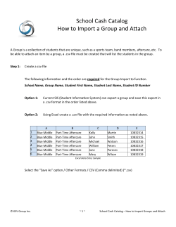


© Copyright 2026