
KLIC-N-PRINT 3D User Manual September 25, 2014
KLIC-N-PRINT 3D User Manual http://knp3d.com/ September 25, 2014 Table of Contents Table of Contents .......................................................................................................................................... 2 1. 2. Introduction............................................................................................................................................ 6 1.01 User Manual Options .................................................................................................................... 6 1.02 Safety ............................................................................................................................................ 7 1.03 Warranty ........................................................................................................................................ 7 1.04 Support .......................................................................................................................................... 7 1.05 Unpacking ..................................................................................................................................... 8 1.06 Contents ........................................................................................................................................ 8 1.07 Other Tools and Supplies .............................................................................................................. 8 1.08 Parts of the KNP3D ....................................................................................................................... 9 Setting Up............................................................................................................................................ 11 2.01 Hardware Setup .......................................................................................................................... 11 2.02 Software Setup ............................................................................................................................ 11 2.02.1 Slic3r .................................................................................................................................... 11 2.02.2 KNP3D Converter ................................................................................................................ 12 2.02.3 Slic3r Profiles for KNP3D ......................................................................................................... 13 3. 4. 2.03 Control Panel............................................................................................................................... 13 2.04 Leveling the Build Plate ............................................................................................................... 14 2.05 Loading Filament ......................................................................................................................... 15 Your First Print .................................................................................................................................... 17 3.01 Overview of the 3D Printing Process .......................................................................................... 17 3.02 Load Profiles into Slic3r .............................................................................................................. 18 3.03 Print a Test File ........................................................................................................................... 18 More About Slic3r ................................................................................................................................ 21 4.01 Important – Read This! ................................................................................................................ 21 4.02 Slic3r Tabs .................................................................................................................................. 21 4.03 Understanding Profiles ................................................................................................................ 22 4.04 Changing and Saving Settings .................................................................................................... 23 4.05 Plater ........................................................................................................................................... 25 4.05.1 Add ..................................................................................................................................... 25 4.05.2 Delete and Delete All 4.05.3 Arrange ............................................................................................................ 26 ................................................................................................................................. 26 4.05.4 Duplicate and Remove Duplicates 4.05.5 Rotate ....................................................................................... 26 .................................................................................................................................. 26 2 4.05.6 Scale ................................................................................................................................... 27 4.05.7 Split ..................................................................................................................................... 27 4.05.8 View/Cut .............................................................................................................................. 28 4.05.9 Settings ................................................................................................................................ 29 4.05.10 File Info .................................................................................................................................. 29 4.06 5. More Information on Slic3r .......................................................................................................... 29 More About Printing ............................................................................................................................ 30 5.01 Important – Read This! ................................................................................................................ 30 5.02 Preheat ........................................................................................................................................ 30 5.03 Pausing the Print ......................................................................................................................... 31 5.03.1 Pause ....................................................................................................................................... 31 5.03.2 Pause at ZPos .......................................................................................................................... 32 5.03.3 Cold Pause ............................................................................................................................... 32 5.04 Changing Temperature and Speed During a Print...................................................................... 33 5.04.1 Changing the Speeds During a Print ....................................................................................... 33 5.04.2 Changing the Extrusion Temperature During a Print ............................................................... 33 5.05 Unloading Filament While Not Currently Printing........................................................................ 34 5.06 Changing Filament During a Print ............................................................................................... 35 5.07 Printing with ABS and Other Filaments ....................................................................................... 36 5.07.1 ABS .......................................................................................................................................... 36 5.07.2 PVA Support ............................................................................................................................ 37 6. 7. 5.08 Printing Duplicates ...................................................................................................................... 37 5.09 Skirt and Brim .............................................................................................................................. 38 5.10 Support Material .......................................................................................................................... 38 5.11 Two Color Printing ....................................................................................................................... 39 5.12 Using the Left Extruder Only ....................................................................................................... 42 5.13 Printing a Solid Object as a “Vase” ............................................................................................. 42 5.14 Organizing Files on the SD Card ................................................................................................ 43 Post Processing .................................................................................................................................. 44 6.01 Removing the Object ................................................................................................................... 44 6.02 Removing Support Material......................................................................................................... 44 6.03 Sanding the Object ...................................................................................................................... 44 6.04 Gluing Printed Objects ................................................................................................................ 44 6.05 Other Finishing ............................................................................................................................ 44 Maintenance ........................................................................................................................................ 45 7.01 Build Plate ................................................................................................................................... 45 7.02 Extruder Cleaning ....................................................................................................................... 45 3 7.03 Cleaning the Rods ....................................................................................................................... 45 7.04 Storage of Filament ..................................................................................................................... 45 Appendix A Troubleshooting ....................................................................................................................... 46 Appendix B Slic3r Settings .......................................................................................................................... 48 B1 Print Settings ..................................................................................................................................... 49 Print Settings > Layers and Perimeters .............................................................................................. 49 Print Settings > Infill ............................................................................................................................ 50 Print Settings > Speed ........................................................................................................................ 51 Print Settings > Skirt and brim ............................................................................................................ 52 Print Settings > Support Material ........................................................................................................ 52 Print Settings > Notes ......................................................................................................................... 53 Print Settings > Output Options .......................................................................................................... 53 Print Settings > Multiple Extruders ...................................................................................................... 54 Print Settings > Advanced ................................................................................................................... 54 B2 Filament Settings ............................................................................................................................... 54 Filament Settings > Filament .............................................................................................................. 55 Filament Settings > Cooling ................................................................................................................ 55 B3 Printer Settings .................................................................................................................................. 56 Printer Settings > General ................................................................................................................... 56 Printer Settings > Custom G-code ...................................................................................................... 56 Printer Settings > Extruder 1 (or Extruder 2) ...................................................................................... 57 Appendix C Control Panel - Utilities ............................................................................................................ 58 Map of the Menus on the KNP3D Control Panel While Not Printing ...................................................... 58 Map of the Control Panel Menus During Printing.................................................................................... 59 C1 – Utilities Menu Page 1 .................................................................................................................. 59 C2 – Utilities Menu Page 2 .................................................................................................................. 59 C3 – Utilities Menu Page 3 .................................................................................................................. 60 C4 – Utilities Menu Page 4 .................................................................................................................. 60 C5 – Utilities Menu Page 5 .................................................................................................................. 60 C6 – Monitor Mode before Print Begins .............................................................................................. 60 C7 – Preheat Settings ......................................................................................................................... 60 C8 – Bot Statistics ............................................................................................................................... 61 C9 – Filament Odometer ..................................................................................................................... 61 C10 – Profiles (for Preheating)............................................................................................................ 61 C11 – Jog Mode .................................................................................................................................. 62 C12 – General Settings ....................................................................................................................... 62 C13 – Monitor Mode after Print Begins ............................................................................................... 63 4 C14 – Statistics ................................................................................................................................... 63 Appendix D Specifications .......................................................................................................................... 64 Acknowledgements ..................................................................................................................................... 65 5 1. Introduction1 Thank you for purchasing a KNP3D! At KNK USA we are committed to providing the very best customer support for our products. If you are new to 3D printing, remember that it’s not like using a regular printer. It’s not meant to be fast and it’s not meant to be used as a production machine. 3D printing is a fabrication process and, with each print, you are essentially “growing an object.” You will learn about the variables which affect each print (such as temperature, speed, layer thickness) and you will learn how these variables work in combination to produce amazing results! So, let’s get started! Before attempting to operate your KNP3D, please read Chapters 1 – 3. It’s important to get the KNP3D set up properly, the plate leveled, and the proper settings loaded. Take note of anything marked IMPORTANT or in red type. 1.01 User Manual Options This is a preliminary user manual and will be greatly expanded in the future. Please check back regularly for updates. This user manual is published in three formats: an interactive online manual, a downloadable interactive manual, and a PDF version. All three contain the same information; the format options are for your convenience. The following shows the functions of the various icons in the two interactive versions: Turning Pages: To turn pages, click on arrows, enter a page number, click or swipe on the lower corners of the pages, or click on triangles on right or left sides of pages. Enable Full Screen: Click for Full Screen mode. Press Esc or click on icon to return to regular mode. Print: Select pages to print to your printer. It is recommended that you do not print the entire manual as it is updated every six months or so. Bookmark: Table of Contents opens and you can click on any chapter, section, or subsection to immediately access. Thumbnails: Displays the thumbnail images for all pages in the book. Sound: Click to turn off or turn back on the page flipping sound. Zoom: Zoom in and out, as needed. You can also double click on a page to zoom in or out. Note that while zoomed in, moving the mouse automatically scrolls the page up and down. Search: You can search by any word(s) in the manual. Click on the Search icon, enter the word(s), and all pages with that word or words will be listed. Click on a listing to be taken to that page. In future updates to this user manual, look for the following icon: online videos covering that section of the user manual. 1 These icons will be linked to © 2014 Accugraphic Sales, Inc. All Rights Reserved 6 1.02 Safety Please be aware of the following safety guidelines when working with the KNP3D: Hot Elements: Do not touch the heated build plate or extruder nozzles while the KNP3D is printing. At the end of the printing process, wait for the printer to cool down before touching the extruder head or build plate. This can take around 15 to 20 minutes. Fire Hazard: Do not place flammable materials near the KNP3D. Pinch Points: Keep hands, long hair, jewelry, etc. away from the moving parts. Risk to Children: Please supervise children around the printer while it is heating, as well as printing. Also note that small printed items could pose a choking hazard. Eye Protection: When removing support material on finished models, please use safety glasses to protect your eyes. Adequate Ventilation: When printing with ABS filament, a pungent odor will be emitted. Please operate the KNP3D in a well-ventilated room but avoid any direct air blowing on the printer as this can interfere with temperature control. Movement and Touching: Do not move the KNP3D or touch any circuitry while it is plugged in. Recommended Materials: Only use the recommended filament types sold at www.knp3d.com. If you are interested in trying a different filament, please contact KNK USA first to determine if the KNP3D is designed to print that material. 1.03 Warranty IMPORTANT: If a KNP is damaged during the initial shipment to the customer, then your dealer should be notified as soon as possible. If damages are reported later than three weeks after delivery, then it will be the responsibility of the owner to ship the damaged KNP back to KNK USA for repair. The one year parts and labor warranty covers parts for both accidental damage, as well as wear and tear. If warranty work is required, the owner is responsible for shipping costs to and from KNK USA. Discounted shipping will be provided by KNK USA. KNP3D owners outside the USA should contact their dealer for procedures regarding warranty work or shipping damage. It is also recommend that you retain the original box with packing materials in case you ever need to ship your KNP3D. 1.04 Support If you need additional assistance after reading this manual, please visit our forum at http://knkusa.com/forums/. Click on the KLIC-N-Print 3D category listed in the right side menu. We are also available by filling out a contact form at: http://knp3d.com/contact-us/ or by calling 800268-3672. If you purchased your KNP3D from one of our authorized resellers or distributors, please contact them as your first line of support. 7 1.05 Unpacking When unpacking the KNP3D we recommend placing the box on the floor. Open the top of the box and remove the cartons that surround the printer. Next, remove the printer by lifting it by the top metal frame. Do NOT remove the printer by lifting it by the cables. Take note that the two boxes at the bottom of the shipping box contain the power cable, USB cable and the filament guides. Place the KNP3D on a work surface. A 3D printer should be operated in a dust-free, non-humid room with a temperature of 65°F (18°C) or warmer. If printing ABS filament, also make sure the room has adequate ventilation. Open the box that contains the KNP3D extruder and remove the box from the printer. The build plate should now be visible. You’ll notice a thin layer of Kapton tape covering the build plate. Do not remove this film. This is the surface material on which you’ll eventually be printing. Next, the build plate needs to be raised. This can be done by manually rotating the large threaded screw clockwise directly behind the build plate. Raise the build plate until you can easily access the two boxes beneath which contain spools of filament. Carefully remove these as well as any remaining packaging. 1.06 Contents Please verify that you have received all of the following: KNP3D Printer USB Cable Power Cable 8 GB SD Card 2 randomly-selected one lb. rolls of PLA filament Hex wrench set 2 filament roll holders Sheet of Plastic Heat Bed Tape Sheet of Paper Heat Bed Tape 1.07 Other Tools and Supplies Owners of 3D printers often find some of the following items useful. If you have other suggestions, please post at our user forum, linked in Section 1.04, and we’ll include them in future updates! Safety Glasses – To protect your eyes while removing support material Cut-Resistant Gloves – To protect your hands while removing support material 8 Paper Heat Bed Tape – Used to cover the build plate when printing with PLA Plastic Heat Bed Tape – Used to cover the build plate when printing with ABS Artist’s Palette Knife or Metal Spatula – Used to remove printed object from the build plate Plastic Scraper – Used to apply tape to the build plate; aids in removing wrinkles Calipers – Used to measure the filament diameter (in case off-spec filament is suspected) Wire Cutters – Used to remove support material on printed objects Scissors – Used to snip off the end of filament (filament can have stringy ends after unloading) Lint Free Cloth – Used to wipe off dust Sandpaper – Used to smooth any rough edges on the printed object File – Used to smooth any rough edges on the printed object 1.08 Parts of the KNP3D Control Panel Y Axis Rods (2) SD Card Reader Extruders (2) X Axis Rods (2) Z Axis Limit Switch Z Axis Rods (2) Y Axis Motor Build Plate Build Platform Build Platform Knobs (3) Case Front of KNP3D 9 Extruder Levers (2) Extruder Fans (2) Nozzles (2) Z Threaded Rod Interior of KNP3D Extruder Cable Filament Guide Tubes (2) Filament Guide Mounts (4) Filament Spool Spool Holders (2) Power Outlet and Power Switch USB Port Reset Back of KNP3D 10 2. Setting Up 2.01 Hardware Setup Install the extruder: (1) Start by manually turning the large threaded screw counterclockwise to lower the build plate all the way down. (2) Open the box which contains the extruder and remove it from the plastic sleeve. (3) Place the extruder on the extruder mount, making sure the cooling fans are facing forward. (4) Once in place, locate the hex wrench and two silver bolts (found in the same accessory box as the extruder). (5) Tighten the two bolts on the bottom side of the extruder. Attach the spool holders: (1) Open the two long boxes that were on the bottom of the shipping carton to locate two spool holders. (2) On the back of the KNP3D located the two holes for mounting these holders. (3) Install by unscrewing the outermost nut on the spool holder and then inserting the holder into the hole and tightening the nut from inside the KNP3D. Attach the filament guide tubes and filament: (1) Locate the two filament guide tubes. (2) Slip each tube into the fasteners on the back of the KNP3D and screw the fasteners securely. (3) Place a roll of filament on the right spool of the KNP3D, making sure the filament will feed up from the bottom side of the spool, straight up into the guide tube. (4) Loading the filament into the extruder will be covered in Section 2.05. Connect to an outlet: (1) Plug the power cable into the power port on the back of the printer. (2) Be sure the power switch is turned “off” before plugging the power cord into a power outlet. (3) Turn off the power when not using the printer. Unplug from your power outlet if the printer will not be used for a long period of time. 2.02 Software Setup There are a few pieces of software you’ll need in order to create files that the KNP3D uses: 2.02.1 Slic3r Slic3r is the tool you need to convert a digital 3D model into printing instructions for your 3D printer. It cuts the model into horizontal slices (layers), generates tool paths to fill them, and calculates the amount of material to be extruded. 11 Windows Installation: Download Slic3r from this link: http://knp3d.com/software/. Select a file with “stable” in the name and then choose either x64 or x86, depending on your computer: a 64 bit computer or an older 32 bit, respectively. Slic3r is a self-contained executable, requiring no installation. You simply download it, extract it, and it’s ready to use. You will find there are two executable files: slic3r and slic3r-console. You only need to use slic3r. We recommend saving this slic3r file somewhere accessible, such as your Desktop, or creating a shortcut icon on the Desktop. The first time you open slic3r, the Configuration Assistant window will open. Click on Cancel as you will need to switch to Expert mode. This is covered in Chapter 3. Mac OSX Installation: Download Slic3r from this link: http://knp3d.com/software/. Select the file with “stable” in the name. Double click the downloaded DMG file. Once Finder opens, drag the Slic3r icon into your Applications folder. The first time you open Slic3r, the Configuration Assistant window will open. Click on Cancel as you will need to switch to Expert mode. This is covered in Chapter 3. Note: You may receive a message that says “’Slic3r’ can’t be opened because it is from an unidentified developer.” If so, then in your Mac’s System Preferences, select Security & Privacy and click the lock icon that reads “Click the lock to make changes.” Then set “Allow applications downloaded from: ‘Mac App Store and identified developers’” to “Anywhere”. Start Slic3r. Once running, if you’d like, you may reset Gatekeeper to “Mac App Store and identified developers”. 2.02.2 KNP3D Converter KNP3D Converter is a post processing application. This will take the gcode files from Slic3r and convert them into x3g, a format the KNP3D understands. Download KNP3D Converter from this link: http://knp3d.com/software/ Windows Installation: KNP3D Converter is a self-contained executable, requiring no installation. You simply download it, extract it, and it’s ready to use. We recommend saving it somewhere accessible, such as your Desktop, or creating a shortcut icon on the Desktop. Mac OSX Installation: Double click the downloaded DMG file. Once Finder opens, drag the KNP3D Converter icon into your Applications folder. The KNP3D Converter can be used either of two ways: 12 Open KNP3D converter, browse to locate the input .gcode file created in Slic3r, choose an output location (e.g. SD card) and click on Convert. Alternatively, after creating the .gcode file in Slic3r, open the folder where the file was saved. Drag and drop this file onto the KNP3D Converter icon and it will automatically generate the .x3g file and save it in the same folder. 2.02.3 Slic3r Profiles for KNP3D To get you started with appropriate settings for printing, some profiles are set up and available to download. A few things to know about these profiles: The profiles contain settings for the KNP3D itself, the filaments you can use, and some initial printing recommendations (temperatures, speeds, thicknesses). There are different profiles for fast printing (draft mode), medium printing (default mode), and slow printing (high quality mode). Important: There are no “perfect” profiles that work on every single type of object you might choose to print. For example, a small flat object will mostly likely need a different profile than a tall thin object. So, you will need to be doing test prints and adjusting settings as needed. When you find the best settings for a particular type of object, you can save those settings with a new profile name and build your own library of settings. Use the following link to download a profile bundle (single file) containing the settings to get you started: http://www.iloveknk.com/Support/KNP3D/Files/Profiles/ Instructions for loading this file into Slic3r will be covered in Section 3.02. 2.03 Control Panel When you initially power up the KNP3D, a welcome screen will appear for a few seconds, followed by the Main Menu: To maneuver through the menu, press the buttons on the panel to the right of the display: Move up the menu. Go back to prior menu. Go to next menu. Select current option. Move down the menu. 13 Main Menu options include: Small arrow indicates currently selected item in menu. Browse SD card for a file to print. See Section 3.03 and 5.14 Begin preheating filament and build plate. See Section 5.02 Go to Utilities Menu: See below and also Appendix C. Utilities Menu options include: Check current temperatures Change preheat settings See Appendix C7 Load or Unload Filament See Sections 2.05 and 5.05 Level Build Plate See Section 2.04 Additional settings within the Utilities Menu are presented in Appendix C. 2.04 Leveling the Build Plate The leveling procedure is very important, but also very straight forward! You’ll need a single sheet of printer paper. (1) Turn on the power to the KNP3D. Place the sheet of paper on the build plate. (2) On the control panel, select Utilities and then select Level Build Plate. The current temperatures of the extruders and platform (build plate) will appear: (3) The extruder head will first move over to the right side and the build plate will rise up. Then the extruder will move to the center of the build plate. The display will now show this: (4) You can now manually move the extruder head in different positions over the build plate by sliding it left / right or pulling it forward / pushing it backward. Since this is a manual process, you can move the extruder head to as many positions as you would like. However, for this calibration, you will be moving the head to three different positions: over each of the three adjustment knobs (located below the build plate). In each position you will adjust the height so that it just touches the piece of paper. 14 (5) To begin, move the extruder head above the front right knob. (6) If you cannot slide the paper between the extruder and the build plate, you have it too high and need to turn the knob to the left. If you can slip the paper between the build extruder and build plate, with room to move the paper up and down, you have the build plate too low so turn the Raise knob to the right: Turn the knob to the right to raise the build plate (Right = Raise) Turn the knob to the left to lower the build plate. (Left = Lower) Lower (7) Once you have the front right knob adjusted, move the extruder head to the front left and repeat Steps (5) and (6). You want to avoid having the nozzle dig into the plate so if, while moving, the paper suddenly has a lot of resistance, stop and lower the plate at that point. (8) After you have the front left knob adjusted, move to the center back. Repeat Steps (5) and (6). (9) Upon adjusting at all three locations, repeat Steps (5) – (9) and adjust again. It usually takes three or four repeats at each location to get the leveling just right. (10) If you’re satisfied that the plate is level and the paper will slide with just a little resistance in all three locations, press K. Note that this calibration procedure can be repeated any time you feel a need to check it. 2.05 Loading Filament (1) Before loading the filament, be sure to disconnect the guide tube from the top of the extruder by pulling the plastic tubing out of the hole in the acrylic plate. (2) Feed the filament into the bottom of the guide tube until it comes out the other end. If you plan to use only one filament, the right side is considered the default. Remember that the spools should be loaded so that the filament feeds straight up into the guide tubes: (3) Extend the filament several more inches so that you can easily hold it between your thumb and index finger. Use scissors to cut off and discard about one inch of the end. (4) Next, on the control panel, go to: Utilities > Filament Loading > Load Right: (5) The extruder head will now begin heating up to 230°C. This will be displayed on the control panel and, as the temperature increases, the progress bar will expand: 15 (6) When the extruder reaches the preset temperature, the KNP3D will play a little tune, prompting you to load the filament. The display will show: (7) Press down on the small extruder lever on the right side of the right extruder and feed the filament firmly down into the hole on the top. Extruder Lever (8) Once in, let go of the extruder lever and the filament will begin to slowly feed into the extruder. Place the end of the guide tube into the hole in the acrylic plate. After a few seconds, you’ll see filament streaming out of the nozzle. (9) You will most likely see a different color for the first few seconds. Not to worry. Every machine is tested with a randomly selected colored filament before it’s packaged for shipment. Once the proper color filament starts streaming out of the nozzle, allow it to continue feeding through for another 5 10 seconds. (10) Press K to exit. Turn off the KNP3D. (11) If, at any time during the loading process you need to cancel, press the left button on the control panel and the option to cancel will appear. (12) To learn how to unload filament, refer to Sections 5.05 and 5.06. 16 3. Your First Print 3.01 Overview of the 3D Printing Process 3D printing on a KNP3D uses an additive manufacturing process called Fused Filament Fabrication, allowing users to turn computer-designed 3D models into physical objects. Any 3D program which will export in .stl, .obj. or .amf format can be used. The following are several programs to consider, if you are new to designing in 3D: Rhino3D Moment of Inspiration Any of a number of free 3D design programs You can also locate .stl files on the Internet to download. Many of these are free files! To locate these, just search on “free stl files” at google.com. For now, a test file will be provided at a download link in Section 3.03. A program (typically referred to as a slicer), opens the .stl file and “slices” it into very thin layers, which is then translated into instructions that the printer understands. We recommend using Slic3r, which you downloaded in Section 2.02.1. There are different types of materials (aka filaments) which can be used for printing, such as PLA, ABS, nylon and more. These plastics are fed through the printer’s extruder which melts the plastic and squirts it out of a nozzle (kind of like a miniature glue gun). The printer extrudes layer on layer until the object is complete. Below is a flow diagram of the process used with the KNP3D. Most steps involve just a click or two, so do not fret over the number of steps. Once you’ve performed this procedure a few times, it will be easy to remember. 17 We recommend you follow all of the steps in this chapter as a way to test your KNP3D. You can use either of the free PLA filaments that were shipped with your KNP3D. PLA (Polylactic Acid) is a popular filament to use because it readily sticks to the build plate, has a pleasant odor when heated, and is less likely to warp than the other commonly used thermoplastic, ABS. 3.02 Load Profiles into Slic3r In this section, the profile bundle downloaded in Section 2.02.3 will be loaded. As mentioned before, these profiles are starting points for prints. As you test and create your own successful models, you’ll want to save your settings under new profile names. We also encourage you to share your results at our user forum: http://knkusa.com/forums. In Chapter 4, the most important features of Slic3r will be covered. Additionally, you can learn more about Slic3r by referring to its user manual at this link: Slic3r User Manual. The first time you open Slic3r, the Configuration Assistant window will also open. Click on Cancel as you will need to switch to Expert mode. To switch to Expert mode, go to File > Preferences (on a Mac, go to Slic3r > Preferences) and select Expert in the drop down menu and mark all three boxes. Then click on OK: You will need to restart Slic3r so that the menus will switch to the Expert mode. Once Slic3r has reopened, go to File > Load Config Bundle (note: not the top menu item, but the third one in the menu). Browse to locate the “KNP3D Profiles” file you downloaded in Section 2.02.3. Select it and click on Open. 3.03 Print a Test File You’re now ready to make your first print. We’ve created a simple 3D key fob to be used: Download Key Fob (1) Download this .stl file and then open up Slic3r. (2) On the Plater tab (top left), click the Add button. Browse and locate the downloaded .stl file and click on Open. The file name will appear under Name: 18 Click on Add and select the test file you downloaded. File name will appear here. Select the same profiles shown here. Top view of file Thin gray border is the skirt that will be printed first. Click on Export GCode when ready File information (3) On the right side, the profiles to be used in this print will need to be selected. Click on each dropdown arrow and select the Profile name shown in the screenshot above. (4) Note that the upper profile under Filament is for the right extruder and the lower profile is for the left extruder. There will be situations in which you will need to select a profile for that second extruder if using it for your print. (5) Click the Export G-code button over on the right side. A window will open and you will be able to now click on Save. Note where the file will be saved and change the location, if desired. (6) Next, we need to convert the gcode file to x3g. Open the KNP3D converter program and click the Browse button to the right of Input File. Locate and choose KNP3DCube.gcode and click Open. (7) Click the Browse button to the right of Output File. Here you can save the file directly to your SD card, or you can save it to a different directory and copy to your SD card later. For now, save to the SD card and click on Save. (8) Now click on Convert. Once complete, a window will open letting you know the file has been successfully converted: Gcode file selected here Location for saving converted file Click on Convert (9) Turn on the KNP3D. (10) Insert the SD card into the 3D printer. The SD card slot is found on the top right corner of the KNP3D and the card is inserted with the label facing forward: 19 Insert the SD card here with the label facing forward. (11) From the KNP3D control panel, select Print from SD and then select the KNP3DCube.x3g file. (12) Your KNP3D should begin its first print after the build plate and extruder reach the preset temperature. (13) Note that a skirt is always printed first to ensure the filament is flowing smoothly. If, after two passes, there is no filament or the filament is not sticking to the build plate, cancel the print by pressing the left key on the control panel. Refer to Section 5.01. (14) The screen display during printing, which is called Monitor Mode, will provide the following information: Percent completion Current / Target temperatures (15) When the printing is complete, the extruder will return to the back right corner. Allow to cool for a few minutes. (16) To remove the model, use a sharp flat tool, such as a thin metal spatula or an artist’s palette knife. Gently slip the tool under the outer edge of the model in several different spots. Then slip it under again and twist. The model should pop off (separate) easily from the plate. (17) On the control panel, the following screen appears showing the length of time for that print, as well as the option to print another. If you are finished printing, turn off the power to the KNP3D. Amount of filament used for last print. Printing time for most recently completed print Option to repeat the last print (Note: the Print Time and Filament values above were for a different print, not the test object. 20 4. More About Slic3r 4.01 Important – Read This! Here’s a list of the key things to check when using Slic3r: Do not automatically upgrade to the latest version of Slic3r without seeing an announcement by KNK USA at the User Forum. It’s important that any changes made in Slic3r not impact the KNP3D in unexpected ways. KNK USA will thoroughly test all new stabilized versions before recommending them to KNP3D owners. Upon importing an STL file, always check the Size in the Info window. If the file being imported was designed in inches, then it will not print the correct size unless it is scaled in Slic3r, which uses mm as a default unit. This is covered in Section 4.05.6. Under the Info section of Slic3r, you will see a parameter called Manifold. Always make sure Manifold says “Yes”, which indicates that edges are properly aligned in the model. Refer to Section 4.05.10. Before exporting to G-code, make sure the correct profiles are selected under Print Settings, Filament, and Printer Settings on the right side of the Slic3r window. Also remember that you need to adjust settings based on the type of object you’re printing. This will be covered in the remainder of this chapter and in Appendix B. Are these the correct Profiles for the print? Check the Size which is shown in mm! Verify that Manifold says “Yes” 4.02 Slic3r Tabs Notice the four tabs across the screen: Plater, Print Settings, Filament Settings, and Printer Settings: 21 Each of these tabs accesses certain settings that will, at one time or another, need to be changed from the defaults. Some of these settings may remain constant once changed. Others will need to be adjusted depending on the particular object being printed or filament being used. The functions of these tabs are: Plater tab is used when importing the .STL, .OBJ, or .AMF file and then making changes such as scaling, duplicating, and rotating. This tab will be used with each new model you wish to print. Refer to Section 4.05 to understand the purpose of the icons in the Plater window. Print Settings are related to the print itself, such as the layer height, fill density, and various speeds. This tab will be used each time a different type of printing is needed, such as changing the quality of the print or adjusting settings related to the type of model. Filament Settings are related to the filament material, such as thickness, required temperature, cooling options. These settings will normally remain the same unless you change to a different type of filament, such as switching from PLA to ABS. Printer Settings are related to the KNP3D itself, such as the bed size, firmware type, and number of extruders. 4.03 Understanding Profiles When you loaded the “KNP3D Profiles” file in Section 3.02.2, there were 10 different profiles and these profiles then appeared in the drop down menus on the right side of the main screen: Different profiles available for each tab A profile contains settings from one or more of these three tabs: Print Settings, Filament Settings, and Printer Settings. The 10 imported ones are for the following applications. Again, remember that you will be making adjustments based on your own experiences for different types of shapes. 22 A profile can contain settings for just one tab or for more than one tab: For example, one could have a profile of settings pertaining to ABS which was set up under Filament Settings. One might also set up Print Settings more suited for ABS than for PLA. These two profiles could be saved under separate names - ABS Print and ABS Filament. Alternatively, both sets of settings could be saved under the same name and then would be located under both menus. Let’s assume that the same name “ABS Default Print Settings” was used for saving both the changes made under Filament Settings and under Print Settings. That means this profile would then be available under the Filament Settings menu and under the Print Settings menu, but not under the Printer Settings menu (because it was never saved under that tab, using that name). ABS Default Print Settings can be selected in these menus, but not under Printer. 4.04 Changing and Saving Settings The process of testing different variables is part of owning a 3D printer and getting the best results from it. It’s usually advisable to change only one variable at a time and to take notes. You may find that instead of trial and error, you’d prefer to have some specific recommendations. Feel free to post on the user forum asking for help! We urge you to also post your .STL file and a photo of your print with a description of any issues you had with that print. You will get the help you need and, at the same time, help future owners who read the forum and see your post. In this section, some typical changes will be made and saved, so that you’ll understand how the process works. This same method is used for any changes under the Print Settings, Filament Settings, and Printer Settings tabs. You will see there are many settings available in Slic3r. Note that if you rest your mouse on the input window of any given setting, a popup window will appear describing the purpose of that setting. This is a great way to not only learn the function of that setting, but also to better understand the 3D printing process itself. Also take note that Appendix B and the Slic3r User Manual cover these settings in more detail. Try out the following example and make some changes under Print Settings: (1) Click on the Print Settings tab. (2) Select a profile to change. In this example, you’ll be using the Default, as indicated by the upper blue arrow in the screenshot below. (3) Next, select from the submenu items which appear along the left side. The first one you’ll be changing is part of Layer and perimeters. Thus, click on Layer and perimeters as indicated by the lower blue arrow. 23 (4) The red arrow indicates a typical setting that might be adjusted. Let’s say you wish to try a smaller Layer height which should improve the quality of the print. Change it from 0.2 to 0.15: Select “1Default Quality” Change from 0.2 to 0.15. Select Layers and perimeters (5) Now click on Infill, the next category in the left side menu. Decrease the Fill density, which will speed up the print a bit, to compensate for the lower Layer height. Change the Fill Density to from 15% to 10%. Select Infill IMPORTANT: Once you make a change you need to save these settings on each tab, before moving to another tab. You can either overwrite the settings for this particular profile or you can save and enter a new Profile name, thus retaining the original profile. Normally, it’s a good idea to use a new name since the settings you may find that work well for one object might not work well for the next. Thus, you might want to name the Profile according to the object itself. (6) So, at this point click on the small Save icon and give this new profile a new name, such as “Dog Tag” (assuming that’s the object you’re printing!): Click here to save the new Print Settings Input a new name and click on OK. (7) Now let’s assume you also want to make a Filament Settings change. For example you might want to raise the lower the temperature a bit. Click on that tab and then select the PLA profile: Select PLA Select Filament Change the Extruder Temperatures to 210 and 200. 24 Also save these changes but this is the point at which you have a decision to make. Pick whichever one makes the most sense to you and, with experience, you’ll develop your own preferences. Your options are: Replace the current PLA profile Save it using the same name as the one when you changed the Print Settings (“Dog Tag”) Create an entirely new name for this particular Filament Settings profile, such as “PLA Lower Temp.” If you wish to delete any profiles, go to the appropriate settings tab, select the profile, and then click on the small red “ - ”icon. If that profile is used another other tabs, then it will need to be separately deleted from each one: Click here to delete the “Dog Tag” profile from the Print Settings menu. As a safeguard, you should also save all of your settings by going to File > Export Config Bundle, and selecting a folder on your computer in which to save the configuration. Give it a new name, such as “My KNP3D Profiles”. Note that this new “My KNP Profiles.ini” file can be loaded into Slic3r on another computer, saving you the time of re-entering changes to any settings. Go to File > Load Config Bundle, browse to locate the file, and click on Open. 4.05 Plater As stated earlier, the Plater tab is used when importing the .STL, .OBJ, or .AMF file and then making changes such as scaling, duplicating, and rotating. It also displays the profile selection menus, and the export options for G-code and STL. The following subsections explain the purpose of each button/icon you see while the Plater tab is selected. 4.05.1 Add The Add function is used to import .STL, .OBJ, and . AMF files into Slic3r. You are not limited to adding and printing only one file at a time. For example, in the screen shot below, two different STL files have been imported using the Add button. Both files will be printed and the two files together can be saved as a single STL file by clicking on the Export STL button on the right side. Shapes can also be moved to a different location on the grid by dragging them with your mouse. Use the mouse to drag the shapes, as desired. The thin border around the shapes is the skirt which will be printed first. 25 4.05.2 Delete and Delete All You can delete one or all of the STL files currently loaded. To delete just one of the files, highlight it and then click on Delete. Delete All will delete all loaded files without the need to highlight any of them. 4.05.3 Arrange This function will automatically arrange objects to take up less space. For example, let’s say the two objects were dragged far apart, clicking on Arrange will bring them close together again: Arrange brings the shapes closer together. 4.05.4 Duplicate and Remove Duplicates The Duplicate function allows you to easily add more copies of the highlighted file. Just click on the green icon to add more copies and click on the red icon to delete. Warning, if you only have one left and you click on the red icon you will delete the file from Slic3r and will need to use Add to re-import. Duplicate was used to add 1 more “Boo!” and 4 more bats. 4.05.5 Rotate There are three icons used for rotating: The first two rotate buttons will rotate a highlighted object in 45° degree increments, counterclockwise and clockwise as indicated by the icons. The Rotate button allows you to input the exact degree of rotation desired. When there are duplicates, the rotation will be applied to all: 26 The ”Boo!” shapes were rotated 90°counterclockwise. The bats were rotated 30°clockwise. Note that after using this function you may need to manually drag and separate the shapes, in case any are overlapping as a result of the rotation. 4.05.6 Scale The Scale function is used to resize an imported file. This can be VERY important due to the fact that imported objects into Slic3r are always considered to have been designed in mm. For example, if you designed a button that’s 1 inch in diameter and ⅛ inch thick, that button will be imported as 1 mm in diameter and ⅛ mm thick! That’s a tiny button! In order to resize the button to its original dimensions, click on Scale and input 2540: If you designed the file in cm, then the scaling would need to be entered as 1000. If you wish to simply double the size of a shape, then highlight the file, click on Scale and enter 200. Note that after using this function you may need to manually drag and separate shapes, in case any are overlapping. 4.05.7 Split Split is used to separate individual objects within an imported file. For example, let’s suppose the bat and “Boo” were created together in a 3D design program and imported as a single STL file. Then let’s also suppose you only want to print the bat. By highlighting the file and clicking on Split, the two objects are now separate: 27 Two objects are listed after applying Split. The same file name is used for both objects since there’s no way for Slic3r to know how to name them separately. To determine which is which, highlight one of the names and that object will also be highlighted: The top listing is the bat; the bottom listing is the “Boo!” 4.05.8 View/Cut The View/Cut function has several uses: You can see a 3D representation of the object. Pressing and dragging the right mouse allows you to rotate the shape. You can slice off a desired amount of the object in the Z direction. This could be useful if you wanted to double the X and Y dimensions of a shape but not make it any thicker/taller. For example, when the bat was previously scaled to 200%, it also became twice as thick (increasing from 1.5 mm to 3.0 mm. To return the bat to its original thickness, the following settings could be applied: Amount to cut off, in mm Option to rotate lower part if keeping Part to keep: Upper, Lower or both Click here to complete the cut. Another application for the Cut function is when your object is too large for the build plate or shaped where the bottom will not have sufficient contact area with the build plate to insure a good print. The Cut function can be used to dissect the file into two or more sections for printing. Then, after the individual parts are printed, they can be glued together. Note that this is sometimes visible in items you purchase where you see a seam that joins the object together. This is the same thing! Yet another application, albeit one for an advanced user, involves cutting an object into two or more sections with the intent of using different print settings on those sections. This involves 28 manually modifying the Gcode file, as well, which is why it’s not for a beginner. But remember that the possibility does exist. For more information, refer to this excellent post by Richrap. 4.05.9 Settings In the settings function, changes can be made to certain print, filament, and/or printer settings as “one time changes” only, without altering the current values for any of the configurations. This will be covered in specific printing scenarios later in this manual. 4.05.10 File Info To view the info on a file, highlight it first and then information on the file appears in the Info section at the bottom of the screen. Note that the Size is reported in mm and the Volume is reported in cubic mm. To convert to inches, you’ll need to use a calculator and divide the dimension under Size by 25.4. To convert the volume to cubic inches, divide by 16,387. For cm, divide by 10 and by 1000, respectively. If the size of the object is incorrect, use the Scale function to change it. Refer to Section 4.05.6, under Scale. The Manifold parameter is especially important to check on any new STL file. It needs to indicate “Yes.” A Manifold that says “No” will not export because there are issues with the design. You can attempt to repair the model by going to File>Repair Stl File and selecting the file to be imported again. 4.06 More Information on Slic3r The Slic3r User Manual contains more details on functions and settings, as well as some useful general information about 3D printing. Chapter 5 will cover some of the settings needed for specific applications. Appendix B contains screen shots from the submenus of the Print Settings, Filaments Settings, and Printer Settings tabs. Be sure to reference these screenshots when deciding upon changes. 29 5. More About Printing 5.01 Important – Read This! Here’s a list of the key things to remember when printing: The panic button is the left arrow key on the control panel. If something goes awry during a print, press it and an option to Cancel the print will appear: After pressing left arrow key, option to Cancel Print appears. Do not remove the SD card during the printing process. The print will be interrupted. This is the screen that will appear: When removing a roll of filament, try to keep the filament taut on the roll and tape the loose end of the filament to the spool. Allowing the filament to uncoil can later result in feeding issues when that filament is used again. PLA and ABS require different temperature settings. Make sure you select the correct profile under Filament Settings. More information on printing with ABS is covered in Section 5.07. 5.02 Preheat Because there’s an option to Preheat, one might think it’s a requirement before every print. But it isn’t. Whenever you send a file to print, the KNP3D will automatically preheat the extruder(s) and the build plate before beginning the print. One use for preheating is to save a little time. While you are finalizing your file in Slic3r, you can go ahead and begin preheating the KNP3D. It will be closer to target temperature once you are ready to load your file from the SD card. IMPORTANT: Do not use the Preheat function for an extended period of time as it can cause a filament clog inside the extruder. To initiate preheating, select it from the main menu: If you wish to preheat the Left Tool, then move down in the above menu and press K to turn on the left extruder. 30 Once you select Start Preheating, the screen will change to show the current temperature and target temperature: Current and target temperatures are shown during preheat. No target is shown for L Extruder because it was set to OFF. To cancel the preheating, press the Left arrow key to exit this window and go back to the main menu. Select Preheat again and then select Turn Heaters Off. 5.03 Pausing the Print There may be a reason to pause a print, such as the filament running out or needing to leave the printer unattended. The KNP3D can easily have printing paused and resumed. There are three kinds of pause modes available and are presented in this section. 5.03.1 Pause The Pause mode is used when you need to change a filament spool or, perhaps, remove a stray thread of filament from the build plate. At any time during the print, press the left arrow key on the control panel to bring up the following menu where you can scroll to and select Pause by pressing K: Select Pause and the extruder will move to the back right corner while the build plate drops down. If you select Pause the following screens appear: These screens appear as the extruder moves to the back right corner and the build plate drops. This screen then appears. (This is just the first page of three.) In Pause mode you have a number of options, as shown above in the far right photo. Scrolling down will take you to second page of options. These options are covered in other sections of the manual, as relevant. 31 Once you are ready to resume printing, select Unpause and a new screen appears as the extruder resumes its heating position (front left corner) and the build plate raises: Scroll down to Unpause and press K. Then you will see the screen showing heating being resumed. Once the extruder(s) and build plate are at target temperatures, printing will start again from where it was paused. Note the Pause can be modifed to keep the heat turned on (although this is not typically recommended. If you do want to keep the heat on, refer to Appendix C. 5.03.2 Pause at ZPos Pause at ZPos allows you to have the print stop at a certain Z location (height). This could be used if you are printing, say, a three color design where a change in filament will be required at some point. It can be a little tricky to use because you need to know the exact Z axis location and then also take into account that you are starting at your calibrated build level which might be something like 0.3 mm. Once the print has begun, press the left arrow to bring up the following menu where ZPos can be scrolled to and then selected by pressing K: Selecting Pause at ZPos will stop the printer when it reaches a preset location on the Z axis. The following window will open indicating the current Z axis location. Change that setting to the location where you want the KNP3D to pause the print. Naturally, this will need to be a higher value than what’s shown in this window because a lower location has already been passed. Current Z Axis location: Use the Up button to increase the position. Change to a higher location on the Z Axis and the printer will go into Pause mode at this set point. Use Left arrow to exit without changes; use K to set new ZPos position. When the build plate reaches the ZPos setting, the same thing happens as in the Pause mode. The extruder head moves to the back right corner and the build plate will drop. When you are ready to resume printing, select Unpause. 5.03.3 Cold Pause Cold Pause is used to pause the printing process for an extended period of time. The KNP3D will remain powered on, however all heaters, stepper motors, and LED lights will be shut down. 32 To access the Cold Pause option during a print, press the left arrow to bring up the following menu. Press the down arrow repeatedly to scroll to the third page of this menu. Then select Cold Pause. Press K to activate a Cold Pause. Scroll down The Cold Pause will then proceed in the same manner as the regular Pause, other than you will see the LED lights turn off. You will have access to the same menu items. Once you are ready to resume printing, select Unpause and everything will proceed as described in Section 5.03.1. 5.04 Changing Temperature and Speed During a Print Being able to change the extruder temperature and the speed in the middle of the printing process can be very handy. Perhaps you meant to change the temperature in Slic3r before exporting the file. Perhaps you see something going wrong and want to make a change and try to save the print. Perhaps you just want to experiment with some changes without going back to Slic3r. 5.04.1 Changing the Speeds During a Print Once the print has begun, press the left arrow to bring up the following menu. Then use the down arrow to scroll to the second page. Select Change Speed: Press K to enter Change Speed screen. Scroll down The speeds can be increased or decreased in 5% increments. For the speed change to take effect, you must press K. Press Up arrow twice to increase speeds by 10%. Use Up/Down arrows to increase or decrease speed. Use Left arrow to exit without changes, use K to set new speeds. You can always reenter this screen during the print and return to the original set speed or make another change. 5.04.2 Changing the Extrusion Temperature During a Print Once the print has begun, press the left arrow to bring up the following menu. Then use the down arrow to scroll to the second page. Select Change Temperature: 33 Scroll to and press K to enter Change Temperature screen. Scroll down The temperature can be increased or decreased in 1°C increments. For this change to take effect, you must press K. You can always reenter this screen during the print and return to the original set temperature or make another change. Press Down arrow five times to decrease temperature by 5°C. Use Up/Down arrows to increase or decrease temperature. Use Left arrow to exit without changes, use K to set the new temperature. 5.05 Unloading Filament While Not Currently Printing There are several reasons why you will need to unload the filament at some point: Changing to a new or different spool of filament Not planning to use your KNP3D for an extended period of time (remove filament and store in a dry location) Needing to unclog the extruder. Unloading filament is very similar to the process of loading it. (1) Before unloading the filament, disconnect the guide tube from the top of the extruder by pulling the plastic tubing out of the hole in the acrylic plate. (2) On the control panel, go to: Utilities > Filament Loading > Unload Right: (3) The extruder head will now begin heating up to 230°C. This will be displayed on the control panel and as the temperature increases, the progress bar will expand: (4) When the extruder reaches the set temperature, the KNP3D will play a little tune, prompting you to load or unload the filament. The feeder inside the extruder will begin to push the filament back out. The display will show: 34 (5) If you are trying to clear a clog and get the filament flowing again, then immediately go back to Loading Filament on the control panel and proceed with those steps. Note that you may need to repeat the unloading/loading process several times. (6) Otherwise, press down on the extruder lever on the side of the extruder and gently pull the filament out of the extruder. (7) Press K to exit. (8) Pull the filament out of the guide tube and secure to the spool using a piece of tape. You do not want the filament to unravel from the spool as this can cause feeding issues the next time that spool is loaded. (9) If changing to a different color, remember that there will be residual filament in the extruder nozzle. Allow sufficient time during the loading of the new filament for the prior color to be fully extruded. If desired, a cleaning filament can be used before loading a new filament to not only ensure the prior color is removed, but also to keep the inside of the extruder free of clogs. 5.06 Changing Filament During a Print If you are running out of filament during a print or, say, decide to change colors and the file hasn’t been set up to use the left extruder, then you can access the Load Filament function using this method. Press the left arrow button during the print and then select the Pause option, as shown at the start of Section 5.03.1. The extruder head will move to the back right corner. This position makes it a bit awkward to unload and load filament. Thus, select the Jog Mode first so that you can move the extruder to a more convenient location. Not to worry, the correct position for resuming the print is stored in memory. Just make sure the nozzle is not positioned over the object you’ve already printed as there will be filament streaming down after the new spool is loaded. Scroll down to Jog Mode and press K. In Jog Mode, you use the X and Y screens to move the head to a different location: X control window – press right button to go to Y control window. Y control window – press K when ready to return to Pause menu. Use the up/down buttons to move the extruder left and right. Use the up/down buttons to move the extruder forward and back. 35 Once the extruder is in the desired location, press K. Then press the down arrow to go to the second page of the menu and select Filament Loading. Press K to go to Filament Loading. Proceed with the instructions in Section 5.05 for unloading the current filament. Then load the next filament using the steps in Section 2.05. Once the second filament is streaming from the nozzle, press K to stop the loading. Use a folded lintfree cloth to gently wipe away any filament hanging from the extruder nozzle. Press the left arrow button three times to return to the original menu where you can then select Unpause. The printing will now resume once the printing temperatures are reached. 5.07 Printing with ABS and Other Filaments 5.07.1 ABS ABS (Acrylonitrile Butadiene Styrene) is a petroleum-based plastic that has more flexibility than PLA. Thus it is often a preferred choice when making objects that interlock with one another. ABS requires higher temperatures for printing. The preheat extruder temperature can remain at 230°C but the build plate preheat should be increased to 110°C. The temperatures for printing will be around 230 - 240°C while the build plate will be at around 110°C. This higher heat requirement also means that finished ABS objects can be used in higher temperature environments than PLA objects. ABS emits a strong odor while heated. It can also emit toxic fumes if heated too high! Make sure your room is well ventilated. ABS doesn’t print quite as smoothly as PLA and also has a propensity to warp or curl while on the build plate. It is recommended that KNK USA’s Plastic Heat Bed Tape be used as the surface for printing versus the Paper Heat Bed Tape used for printing PLA. The profile bundle you initially downloaded contains a Filament Settings profile for ABS. Thus, on the Plater tab, be sure to switch to “ABS Settings” on the right side for either or both extruders, as applicable: Change to “ABS Settings” As with PLA printing, finding the best combination of settings for a particular object, may take several experimental prints. 36 5.07.2 PVA Support PVA support material uses slightly lower printing temperatures than PLA. Click on the Filament Settings tab and change the profile for PLA to: IMPORTANT: Remember to click on the Save icon, but this time call these settings “PVA”: Click here to save the new Filament Settings Input a new name and click on OK. Then, on the Plater tab, be sure to switch to PVA on the right side. Since PVA is often used as a support material for PLA, it is chosen, in this screenshot, for the second extruder only. For more information on using both extruders, refer to Section 5.11. Change to “PVA “ Save these new settings by going to File > Export Config Bundle, and select “My KNP3D Profiles”. These settings will be added to the same file with the other profiles you’ve downloaded into Slic3r and created yourself. 5.08 Printing Duplicates There are several ways to print copies of your objects: Option 1: Select “Print Another Copy” from the screen that immediately follows the end of the printing process. This is the only option available for duplicating objects that are larger than half the size of the build plate since you wouldn’t be able to fit two objects without overlapping them. 37 Select this option to have KNP3D immediately begin a repeat of the last print. Option 2 – If you’ve already turned off the KNP3D, then just turn it back on and select the file again from the SD card. Option 3 - In Slic3r, use the Duplicate function to add copies of your object before exporting as a .gcode file. (Refer to Section 4.05.4.) The objects need to be small enough to fit within the boundaries of the build plate which are indicated by the gridded area on the Plater tab. Export the gcode file, convert to x3g, and now that file will print the duplicates as they are laid out on the grid. Option 4 – For really small shapes, the two extruders can print at the same time, making two copies of the same file. To do this, go to Utilities > General Settings > Ditto Printing. Use the Up arrow to change Ditto Printing from OFF to ON: IMPORTANT: don’t forget to turn off Ditto Printing in case your next project is much bigger! 5.09 Skirt and Brim The Skirt function (under Print Settings > Skirt and Brim) prints an outline of your object at a set distance from the outside perimeter. The purpose of the Skirt is to make sure the filament is flowing smoothly from the extruder before the actual print begins. If there isn’t a clean outline after the two loops are completed, stop the print by pressing the left arrow button to bring up the menu for canceling. Typically, it is recommended that 2 loops are used with a distance of about 6 mm from the object. The Brim function is used whenever an object has limited surface area contact with the build plate. Brim will add a set number of mm of material to connect the object to the build plate to provide stability. The usual recommendation is 4 – 6 mm. 5.10 Support Material Support material consists of thinly added layers to prevent collapse or even just sagging during a print. For example, if you are printing a chair or a swing set, or even the St. Louis Arch, there are large portions of the object that are “hanging over air”. Once these types of objects are printed, the support material is removed using wire-cutters or other tools. (Caution: wear safety glasses and cut/puncture resistant gloves!) Some owners will use a dissolvable filament for the support material. When downloading 3D print files from the Internet, always check to see if the designer has mentioned whether or not support material has already been built into the design. If not, then Slic3r provides features to add support to a file. 38 To use the Support function in Slic3r, click on the Print Settings tab and then, on the left side, select Support Material. Then check the box next to “Generate support material”: Slic3r will then determine where support material might be needed for that design. After exporting the .gcode file, you may wish to turn off that setting or you can save it as a new print setting and name it something appropriate. A Raft will build a foundation beneath the object and is an alternative to Brim, covered in the prior section. 5.11 Two Color Printing To use both extruders during a print, it will be necessary to combine two .STL files into a single .AMF file. But even before doing that, the two files need to have the objects positioned so that, when combined, the different parts will print in the correct locations relative to one another. This will need to be done in the original design software. The following two “cylinder” test files can be downloaded and used as examples of this process: http://www.iloveknk.com/Support/KNP3D/Files/Test/ The final object is a two-colored cylinder. Below are screenshots of the two .STL files and then the final combination: To use Slic3r to combine the files: (1) Do not add the files to Slic3r. Start with just opening Slic3r. (2) Go to File > Combine multi-material STL files. (3) A window will open and you can then browse to locate the files you wish to combine. 39 (4) Select the file which will be printed with the filament loaded into the right/default extruder and then click on Open. (5) Now you can select the second file which will be printed with the filament loaded into the left extruder. Click on Open. Note that these two didn’t need to be located in the same folder. (6) You will be prompted to open additional files. Click on Cancel, instead, and a new window will open. (7) In this window, a name for the merged file is created base on the first files name but with a new file extension - .amf.xml. Click on Save. (8) Now, you can use the Add function to import this new merged file. (9) Use the View/Cut function to make sure the two files are arranged as you want them printed. (10) Proceed with the Export G-code and then conversion to .X3G. If you wish to reverse which extruder will print which file (1) First, select the file (under Name) and then click on the Settings button: Then click on Settings Highlight file name (2) Select one of the files and you’ll see that part turn green in 3D preview. This helps you to make sure that the part you want printed a particular color is assigned to the correct extruder : Select the first part Click here to open a menu of settings The selected part turns green (3) Next click on the little green “+” icon to open a menu of settings and select the top choice, Extruders > Default Extruder: 40 Select the top option. (4) The setting will now appear and the value can be changed to 2, the second/left extruder: Change from 0 to 2. (5) Then repeat with the second part by clicking on “1” under Object, clicking on the green “+” icon, and then changing from 0 to 1. Second part is selected Selected part turns green. Change from 0 to 1. (6) Click on OK and proceed to export as G-code. 41 5.12 Using the Left Extruder Only Let’s say you have red filament loaded into the left extruder and blue filament loaded into the right extruder. You want to print an object with red filament only, thus it would be handy to just use the left extruder without having to unload both and then load the blue filament into the right extruder. The original configuration bundle you downloaded contains the profiles for this situation. From the Printer Settings, select “KNP3D – Left Extr Only” and the required change under Custom G-code has been made. Under Print Settings, select one of the profiles with “Left Extr Only” in the name. Then select whether you want the default, fast, or slow settings. The necessary change under Multiple Extruders has been made to direct the left side extruder to be used. Then make any other settings changes that are best for your particular object. Before exporting to G-code, make sure you have the correct profiles select on the right side of the screen: Make sure both the Print Settings and the Printer are using Left Extr Only profiles. 5.13 Printing a Solid Object as a “Vase” The Spiral Vase feature in Slic3r will print a shape with solid bottom, but otherwise hollow. This is a quick way to turn any solid shape into a vase. Print Settings > Layers and Perimeters 42 Print Settings > Infill You should then save these settings under a new profile name, such as “Vase.” Then select this profile under Print Settings and proceed to export as G-code. 5.14 Organizing Files on the SD Card Because only three file names from the SD card can be displayed on the screen, it can become tedious maneuvering through pages of file names. Remember that the list of files will be in chronological order based on when they were saved to the SD card. Thus, when you first view the contents on the SD card, you can use the UP arrow to move to the bottom of the list. There will be occasions when you want to print a file that’s not the most recent one. For that reason, it is recommended that you immediately begin organizing your files into folders and subfolders, so that they will be easier to locate at a later time. In the following example, three folders have been set up. Within “My Files”, two additional subfolders have been created: “Fun Files” and “Craft Files”. Then “Craft Files” is opened to a list of files, as shown. Top level menu on SD Card Subfolders under My Files Files inside “Craft Files” One issue about using folders: if you have mistakenly entered the wrong subfolder and Exit out, you may find that you cannot get back to the top level. In that situation, just eject the SD card and push it back in. The main menu will be back again. 43 6. Post Processing 6.01 Removing the Object After the printing has stopped, wait a few minutes for the object to cool. If you attempt to remove the shape too soon, it can warp or be damaged. To remove the printed object from the build plate, use a sharp flat tool, such as a thin metal spatula or an artist’s palette knife. Gently slip the tool under the outer edge of the model and twist. The model should pop off (separate) easily from the plate. For shapes with a large footprint, it’s advisable to slip the spatula or knife under several spots around the perimeter before attempting to pop it off. 6.02 Removing Support Material Having the right tools always makes jobs easier to complete. For removing support materials, try using needle nosed pliers to twist the support material away from the object. Tweezers can also be used to pick off small pieces. Always use safety glasses and safety gloves when removing support material. Both can be purchased for low prices at Harbor Freight Tools. 6.03 Sanding the Object Sanding by hand (using regular sandpaper) can be used to smooth rough spots on both PLA and ABS printed objects, although ABS objects are prone to whitening. A set of diamond grit needle files also work well for smoothing, especially inside tight corners. They come in different sizes and shapes and a set is very inexpensive at places like Harbor Freight Tools. Some owners of 3D printers use acetone slurries to smooth objects printed with ABS. Because of the safety precautions required, directions for this process will not be covered in this user manual. 6.04 Gluing Printed Objects Objects cut in half can be glued together using Super Glue or other glues designed for plastic adhesion. It’s advisable to print a few small shapes cut in half to test the glue’s strength and make sure you are satisfied with the fit and the resulting seam. 6.05 Other Finishing Printed objects can be painted with acrylic paint. Alcohol inks also seem to work well with PLA printed objects. 44 7. Maintenance Very little maintenance is required for the KNK3D. We suggest a quick rundown of the following procedures to keep your printer in good operating condition. 7.01 Build Plate Keep the build plate clean and free of wrinkles. After a print, make sure all remnants of filament are removed after the printer is at room temperature. If using any kind of tape, make sure the tape is wrinkle-free. Sometimes wrinkled tape can be pulled up and then squeegeed back down again using a plastic scraper. Otherwise, replace the tape when needed. If the build plate has any kind of grease or oil, it can prevent the filament from sticking during a print. If this is the case, it can be wiped down with rubbing alcohol or other degreaser. However, please use the following steps: Turn off the power to the KNP3D. Make absolutely certain the printer is at room temperature. Make sure the degreasing agent is thoroughly wiped off the plate. Do not leave the degreasing agent near the printer. Store it elsewhere before turning the printer back on again. 7.02 Extruder Cleaning The nozzle on the extruder can be cleaned using a lint-free cloth. Make sure the printer has had time to cool to room temperature. To clean the inside of the extruder and nozzle, a cleaning filament can be used at the normal preset temperatures already set on the printer. 7.03 Cleaning the Rods Using a clean lint-free cloth, gently wipe both the smooth and the threaded rods inside the printer. Be sure to clean off any buildup around the linear bearings. Do not apply any form of lubricant or cleaning chemicals to the rods. 7.04 Storage of Filament Retain the silica packets which come with every roll of filament. Store them with the opened rolls of filament in a dry, room-temperature storage area, such as a cabinet or drawer. 45 Appendix A Troubleshooting The KNP3D starts printing without dispersing any filament. Verify that the filament is loaded properly by going to Utilities>Load Filament. Refer to Section 2.05 for additional instructions. _______________________________________ The Kapton tape on the build plate has torn. Remove the Kapton tape from the top surface only. Note that it is also sandwiched between the build plate and the platform beneath. Do not try to remove it from there. Then replace with paper build plate tape or 3M blue painter’s tape (for PLA) or plastic build plate tape for ABS. _______________________________________ Object will not stick to the build plate while printing. Make sure the build plate is clean and there are no wrinkles in the tape which covers it. Go through the Level Build Plate procedure again (Refer to Section 2.04). The plate may need to be raised slightly. If your shape has a small size footprint, you may need to rotate it or add a brim or support. Refer to Sections 5.09 and 5.10. If printing with PLA, make sure you are using a paper build plate tape. If you printing with ABS, make sure you are using the plastic build plate tape and have the build plate temperature raised to 100°C. _______________________________________ The filament is “blobbing up” on the build plate during the print. Go through the Level Build Plate procedure again (Refer to Section 2.04). The plate may need to be lowered slightly. _______________________________________ When the print begins, the build plate doesn’t rise up but the printing process begins anyhow. Go back to Slic3r and verify that that correct profile is selected. This can happen if the wrong GCode Flavor is selected under Printer Settings > Firmware Flavor. It needs to be set to Sailfish (Makerbot). _______________________________________ At the end of the print, the object is stuck to the plate. Use a thin flat metal object, such as an artist’s palette knife or a metal spatula to remove the object. Gently pry in several locations around the front of the object to loosen it. Then try popping it off by twisting the metal device. 46 If necessary, preheat the bed back to 50°C. This should also help loosen the object as it warms up again. _______________________________________ After selecting the file to print, the KNP3D goes back to the main menu and doesn’t start heating or printing. Contact your KNP3D dealer or KNK USA. _______________________________________ The nozzle appears to be clogged with filament. On the control panel, select Utilities > Filament Loading > Unload Right (or Unload Left) and allow to run for a few seconds. Then go back and select Load Right. This process may need to be repeated several times. A cleaning filament can also be used to clear a clogged extruder. _______________________________________ The extruder is just moving around in a tiny circle making a blob. It’s not actually printing the object. Go back to Slic3r and check the dimensions of the object. Mostly likely, it was designed in inches whereas Slic4r assumes all imported designs are in mm. Refer to Section 4.05.6 to use Scale to convert the design. _______________________________________ There is a clicking noise coming from the extruder as it is printing. This indicates the filament is not melting to a high enough temperature for proper extrusion. First try increasing the temperature in Slic3r under Filament Settings > Filament. But do not exceed 220°C for PLA or 260°C for ABS. Otherwise, decrease the printing speeds (go to Print Settings > Speed) so that the filament has more heating time inside the extruder. _______________________________________ The tape on the build plate won’t stay down during the print. It curls up after a few minutes of printing. Cut the tape a little larger than needed and then pinch the excess at the corners, just beneath the plate. If the tape is already cut to size, then cut some masking tape strips to fold around the corners and then pinch those ends, just beneath the plate. The masking tape binding shoud then prevent the build plate tape from curling up. With PLA printing, where the bed temperature is only ~50°C, you can use masking tape to wrap around the sides (or at the corners) and press to the bottom of the build plate. Remove the masking tape if printing with ABS (due to the higher build plate temperature). _______________________________________ The left nozzle is slightly higher than the right one and it’s resulting in printing issues on the left side. Contact KNK USA and we will assist you in making an adjustment to that nozzle. 47 Appendix B Slic3r Settings There will be situations in which changing settings within Slic3r is needed. This appendix contains screenshots from the various settings windows in Slic3r with an indication of which settings are typically adjusted. As you try different settings, you may wish to save these as new profiles, especially if you plan to use them frequently or if you will want to return to the original profile before the changes were made. The directions for saving a profile are in Section 4.04. Remember that when saving changes you may or may not want to overwrite an existing profile. It is often advisable to create new names based on the type of object being printed. The blue arrows indicate where to locate the settings window in Slic3r. The red arrows indicate settings to consider changing based on a particular situation. The number next to a red arrow corresponds to a number in the notes below that screenshot. In the note sections, comments are followed by initials in parentheses. These initials correspond to the source for the recommended settings, such as (KU) means the recommendation came from KNK USA. A list of these sources is below. If you find other sources that you feel should also be included, please submit them to [email protected]. In the note sections, a listing containing slashes: X / Y / Z means that those settings are recommended for high quality / medium quality / low quality printing. As with all settings, you may find your own combinations that work well! We welcome your sharing those settings at our user forum: http://knkusa.com/forums/. Resources for the Slic3r Settings (KU): KNK USA (info supplied by Ron Smith and Chad Youngblut) (SM): Slic3r User Manual - http://manual.slic3r.org/ (AR): Alessandro Ranellucci’s (founder of Slic3r.org) presentation at a 2013 workshop https://www.youtube.com/watch?v=i4zPHULdm9k (PL): 3Dprintedlife video on Slic3r settings - https://www.youtube.com/watch?v=o1HPeovBclc (RR) Richraps’s three posts on “Slic3r is Nicer” – http://richrap.blogspot.com/2012/01/slic3r-is-nicer-part-1-settings-and.html http://richrap.blogspot.com/2012/01/slic3r-is-nicer-part-2-filament-and.html http://richrap.blogspot.com/2012/01/slic3r-is-nicer-part-3-how-low-can-you.html (PT): 3DprinterTips various blog posts - http://3dprintertips.blogspot.com/ (TB): Team Budmen various blog posts - http://blog.teambudmen.com/2013/ (JH): Joan Horvath’s book: Matering 3D Printing, sold by Apress. 48 B1 Print Settings Print Settings are related to the print itself, such as the layer height, fill density, and a host of different speeds. This tab will be used each time a different type of printing is needed, such as changing the quality of the print or adjusting settings related to the type of model. Print Settings > Layers and Perimeters 1. 2. 3. 4. 5. 6. 7. 1. Use 0.1 / 0.2 / 0.3 (KU); maximum at Nozzle Diameter: use 0.4 mm (SM); use larger for prototyping / fast printing; smaller for display objects or more accurate tolerance (TB); Use an even multiplier of the Z motor step size, must be < Nozzle Diameter (JH) 2. Use 0.15 / 0.3 / 0.35 (KU); should be ≥ Layer Height but maximum = Nozzle Diameter (AR) 3. Use ≥ 2 (SM); Use 1-3 (AR) (RR); use 2-3 (PL); increase for strength; decrease for prototyping / fast printing or for decorative objects (TB) 4. Refer to Section 5.13 5. Increase to 4 to improve top layer appearance (KU); use ≥ 2 unless printing with Spiral Vase (SM); use 3 (RR); use 3 – 4 (PL); Increase for strength; decrease for prototyping / fast printing or for decorative objects (TB) 6. Use ≥ 2 (SM); use 3 – 6 (RR); use 3 - 4 (PL); Increase for strength; decrease for prototyping / fast printing or for decorative objects (TB) 7. Try the “Random” setting with artistic/decorative objects (PL) 49 Print Settings > Infill 1. 2. 3. 4. 5. 6. 1. Can lower to 10, but use 25 – 35 for stronger objects (KU); use ≥ 20% to support flat ceilings and use 40% when more mechanical strength is needed (SM); use 10 – 20% for display objects (TB); If object is really small, may need to increase so that there’s enough material present (JH) 2. Normally select “Rectilinear”, “Line”, or “Honeycomb” (which is the strongest). (SM) 3. “Rectilinear” normally selected based on appearance (KU) 4. Increase in order to speed up print time (SM) 5. Turn on to infill/support ceilings only (AR); if used, prints faster but object won’t be as strong (KU) 6. Increase if more strength is needed (PL); Increase when printing short objects (RR) 50 Print Settings > Speed 1. 2. 3. 4. 5. 6. 7. 8. 9. 10. 11. 1. Perimeters: Normally use 40 – 50 but lower to 30 if Layer height is 0.1.(KU); always slower than Infill speed (SM) 2. Small Perimeters: Decrease if there are small holes, islands, or small details (SM) (AR) 3. Ext. Perimeters: Decrease to have a cleaner surface (SM) 4. Infill: Use 40 – 80 (KU); as fast as possible without compromising the integrity of the fill. (SM) 5. Solid Infill: Use 40 – 50 (KU); use slightly slower than Infill but faster than perimeters. (SM) 6. Top Solid Infill: Same or lower than Solid Infill, but lower to 20 if using a Layer height of 0.1 (KU) 7. Support Material: Usually as fast as possible (SM) 8. Bridges: Usually slower than Perimeters. Too slow will result in sagging, too fast will result in broken strands -need to experiment.(SM) (JH) 9. Gap Fill: Usually slow so that extruder doesn’t begin to oscillate. (SM); too slow or too fast can cause messy printing (PT) 10. Travel: Usually as fast as possible to minimize ooze (SM) 11. First Layer Speed: Important that first layer speed is slow (KU); use 30% – 50% (SM); always slower than other layers (AR); use 20% – 25% (PL) 51 Print Settings > Skirt and brim 1. 2. 3. 1. Use 2 (KU); Use 1 or 2 (PL) (RR); Use 2 but increase if switching from a dark colored filament to a light one (JH) 2. Use 6 (KU); Use 2 – 5 (PL); Use 6 (RR); Use 2 (JH) 3. Use 4 – 6 when object has low surface area contact with build plate (KU) (SM) (PL) Print Settings > Support Material 1. 2. 3. 4. 5. 1. Turn on where there’s overhang that will need support (KU) (PL) 2. Keep at 0; allow Slic3r to determine the best settings (SM) 3. Set as desired (SM) 4. Used to build a mesh under the object (PL) 5. Pillars is preferred, but use Honeycomb if having adhesion issues (KU) 52 Print Settings > Notes 1. 1. Use the Notes window for making any comments about the profile, such as what types of shapes print well with these settings. Maybe even list some specific file names you’ve used with this profile. Print Settings > Output Options 1. 1. Add any post-processing scripts that you find available and applicable. One example is the script shown above: It will allow one to by-pass the second step of launching the KNP Converter. In other words, when the Export to G-code button is pressed, a G-code file is created and KNP Converter will also run and create the X3G version. Both files are saved in the same folder as the G-code file folder you select. To set up this script for yourself, just enter the path where you have the KNP Converter program saved. Don’t forget that you will need to set this up for every Print Settings profile you plan to use, but it’s easy to copy/paste from one profile to the next. 53 Print Settings > Multiple Extruders 1. 1. These are set to 2 when using the left extruder only. (KU) (Note: this is already set in the “Left Extr Only” profiles.) Print Settings > Advanced 1. 2. 1. Increase to 110% when using left nozzle only and if that nozzle is a bit higher than the right nozzle. (KU) 2. Use 200% (KU); Needs to calculate to be larger than Nozzle Diameter (SM); ≥ 200% (AR) B2 Filament Settings Filament Settings are related to the filament material, such as thickness, required temperature, cooling options. These settings will normally remain the same unless you change to a different type of filament, such as switching from PLA to ABS. 54 Filament Settings > Filament 1. 2. 3. 4. 1. Use calipers to measure filament size as variance can appear in both different colors and different batches from same manufacturer (JH) 2. For fine tuning extrusion flow rate in ± 0.05 amounts (SM); Also can use if filament is off-spec. Range: 0.9 – 1.1 (AR); 3. Increase temperature if seeing gaps in the infill, decrease temperature if seeing threads of filament. (KU); ABS requires 235 and 230, as set up in ABS profile (KU); First layer is normally ~ 5°C higher than Other layers (SM) (AR); Reduce temperature if Layer height is ≤ 0.1 mm. (RR) 4. Set to 110 and 110 for ABS, as set up in ABS profile (KU) Filament Settings > Cooling 1. 2. 3. 1. KNP3D does not have a cooling fan, thus leave unchecked. (KU) 2. Same case; leave set to 0 (KU) 3. Increase to 40 or 50 if printing an object like a sphere where there is a small contact area on the build plate and the object expands outward. 55 B3 Printer Settings Printer Settings are related to the KNP3D itself, such as the bed size, firmware type, and number of extruders. Printer Settings > General No changes recommended. Printer Settings > Custom G-code A small change was made for the “Left Extr Only” profile. Otherwise, no changes needed unless you wish to study on your own and try out. Gcode explanations available at http://www.reprap.org/wiki/G-code 56 Printer Settings > Extruder 1 (or Extruder 2) 1. 2. 3. 4. 5. 6. 1. Only change if installing a different sized nozzle (KU). 2. Set within the firmware. KNK USA will advise if you are installing a different sized nozzle.(KU) 3. Usually 1 – 2 mm (SM); Can have a strong effect on print quality, increase if stringing is present, usually ≤ 2mm. (JH) 4. Usually 0.1 mm (SM); Try 0.3 mm on shapes with small surface contact (RR) 5. Turn on when a very clean object is needed; increases print time (KU) 6. Usually set to 2 or 3 but not higher than 5 (KU) 57 Appendix C Control Panel - Utilities Map of the Menus on the KNP3D Control Panel While Not Printing Refer to location in parenthesis for information on each function. 58 Map of the Control Panel Menus During Printing C1 – Utilities Menu Page 1 On the control panel, select Utilities on the main menu: Check current temperatures. Refer to Section C6. Change preheat settings Refer to Section C7. Load or Unload Filament Refer to Section 2.05 Level the build plate Refer to Section 2.04 C2 – Utilities Menu Page 2 To access the following additional settings, press the down arrow on the control panel after accessing the menu shown in Section C1: Raises build plate and moves extruder to origin; displays current temperatures Info on current filament usage: Refer to Section C9. Info on KNP3D usage: Refer to Section C8. More settings: Refer to Section C12. 59 C3 – Utilities Menu Page 3 To access the following additional settings, press the down arrow on the control panel after accessing the menu shown in Section C2: Set up preheat profiles. Refer to Section C10. Use arrow keys on control panel to move extruder head. Refer to Section C11. Do not change unless a different sized nozzle is used. These are set for 0.4 mm. Toggles stepper motors on/off – do not modify! C4 – Utilities Menu Page 4 To access the following additional settings, press the down arrow on the control panel after accessing the menu shown in Section C3: Toggles on/off blinking of the LED lights. Restores all settings to factory defaults. Calibrates nozzle lines for both X and Y – Do not modify! Do not access Eeprom! C5 – Utilities Menu Page 5 To access the following additional settings, press the down arrow on the control panel after accessing the menu shown in Section C4: Displays current firmware version. Return to main menu. C6 – Monitor Mode before Print Begins This function displays the current temperatures of both extruders and the build plate. To access Monitor Mode, select from page 1 of the Utilities menu (refer to Section C1): C7 – Preheat Settings Use this function to change the preheat settings to new temperatures. To access Preheat Settings, select from page 1of the Utilities menu (refer to Section C1). (1) Use up/down arrows to select the tool or the platform. Press K. (2) Use up/down arrows to change the temperature. Then press K. Finally, press left arrow to exit menu. 60 C8 – Bot Statistics This function presents info on the KNP3D’s and filament usage. To access Bot Statistics, select from page 2 of the Utilities menu (refer to Section C2). Total hours of printing to date Length of filament used to date. Duration of last print (assuming KNP3D has not been powered off) Length of filament used since last reset (refer to Section C9) C9 – Filament Odometer This function presents info on filament usage and ability to reset. To access Filament Odometer, select from page 2 of the Utilities menu (refer to Section C2). Length of filament used to date. Press K to reset Trip to 0.0. Length of filament used since last reset C10 – Profiles (for Preheating) This function allows one to set up preheat settings and name them. This is useful if you are changing filament types frequently as it will allow you to select a particular profile for that material without needing to change the Preheat Settings. You also have the option to change Home Offsets; however this should only be done if changing to a nozzle with a different diameter. For the 0.4 mm nozzle these offsets should remain at their default settings of X: 151.998, Y: 74.995 and Z: 0.0. To set up a profile, first make any changes to the Preheat settings, as presented in Section C7. Next, to access Profiles, select from page 3 of the Utilities menu (refer to Section C3). Select it and the window of Profile names will open: Select a profile and press K. Upon selecting a profile, four options appear: Change Preheat Heatings and Home Offsets to what is assigned in this profile Display the Preheat Settings and Home Offsets currently assigned to this profile. Change the name of this profile. Current Preheat Settings and Home Offsets will now be assigned to this profile. 61 Selecting Display Config will bring up a window with these settings. The down arrow will need to be used to access the Z Offset and temperatures: C11 – Jog Mode This function allows one to use the arrow keys on the key panel to move the extruder head or build plate to a different position. To access Jog Mode, select from page 3 of the Utilities menu (refer to Section C3). Then press the right and left arrows to maneuver between the X, Y and Z control windows. In each window, use the up/down keys to change the location and the K key to go back to a prior window: X control window Y control window Z (build plate) control window C12 – General Settings Function Setting to Use Comment Ditto Printing OFF (or ON) When turned on, left extruder will print duplicate object at the same time as right extruder. Objects must be less than 1" wide or printing will overlap. Override GC Temp OFF (or ON) Normally leave set to OFF. If ON, print using preheat settings instead of temperatures set inside file on SD card. Pause w/ Heat OFF (or ON) If turned ON, heating continues while in Pause mode. Sound ON (or OFF) Toggles on/off the tune played when reaching target temperature, end of print, etc. Heat LEDs ON (or OFF) Toggles on/off the lights, which change color as the extruders are heating up. LED Colour WHITE (or any of 7 other options) Select which color you prefer for internal LED lights Accelerate ON (or OFF) Extruders 2 Leave set to ON; Acceleration allows for higher quality at faster speeds. Number of extruders on KNP 3D: leave set at 2 62 Extruder Hold OFF (or ON) Leave set to OFF; for use with 3mm printers only HBP Installed YES (or NO) Heated Bed Plate installed? Leave set to "YES" Tool Offset Sys NEW (or OLD) Leave set to NEW; needed for dual extrusion printers Check SD Reads YES (or NO) Leave set to YES; if turned on, errors in SD file will be checked during the print and corrected if possible. P-Stop Control OFF (or ON) Leave set to OFF; not applicable to KNP3D C13 – Monitor Mode after Print Begins If the printing is underway, the Monitor Mode displays this information: Percent completion Current / Target Temperatures If the printing is paused, the Monitor Mode displays this information: Percent completion when Pause was invoked. Current temperatures, which will decrease as printer remains in Pause mode C14 – Statistics During a Pause, the statistics displays this information: Length of print at time of Pause Amount of filament used at time of Pause Z axis position at time of Pause Line of code processed at time of Pause 63 Appendix D Specifications Printer Size: 22.4” x 19.7” x 23.2” (570 mm x 500 mm x 590 mm) Printer Weight: 39.7 lbs. (18 kg) Print Size: 6” x 6” x 9” (152 mm x 152 mm x 229 mm) Technology: Fused Filament Fabrication Number of Extruders: 2 Nozzle Diameter: 0.4 mm Minimum Layer Thickness: 50 microns (0.00196”) Maximum Nozzle Temperature: 280°C Filament: PLA, ABS, PETG, HIPS, PC, Nylon, Flexible Filament Used: 1.75 mm Power Requirement: 110 - 220V / 350W HMI: LCD Interface Connectivity: USB, SD Operating Systems: Windows, Mac OSX Software: Slic3r, KNP Converter 64 Acknowledgements This user manual was started by Chad Youngblut (VP at KNK USA) and I thank him for his initial contributions. He’s also an invaluable teacher and friend. Thank to you Ron Smith at KNK USA for his wealth of information on Slic3r settings and other useful tips for successful printing. Thanks also to Michele Harvey (http://cuttinupdesigns.com/) for providing technical input based on her experiences with the KNP3D. Thank you to my friend, Arlene Russell, for proof-reading this manual and saving me from the embarrassment of typos, clumsy phrases, and inconsistencies! Please send an email to [email protected] if any errors are found in this manual or if you have suggestions for additions or changes. It’s my commitment to keep the content updated and useful to our customers. Finally, a really big thank-you to my family and friends for their patience and their support! Sandy McCauley www.iloveknk.com 65

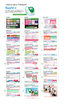


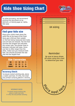


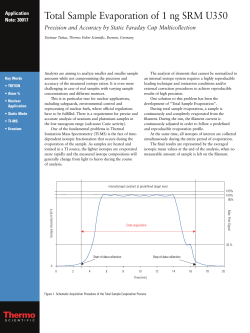
© Copyright 2026