
OPERATOR’S MANUAL Model 104 Batch Freezer
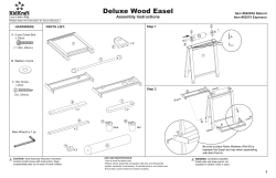
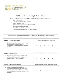
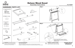
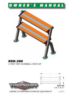
OPERATOR’S
MANUAL
Model 104
Batch Freezer
Original Operating Instructions
053064- M
8/13/08 (Original Publication)
(Updated 7/17/14)
Complete this page for quick reference when service is required:
Taylor Distributor:
Address:
Phone:
Service:
Parts:
Date of Installation:
Information found on data plate:
Model Number:
Serial Number:
Electrical Specs:
Voltage
Cycle
Phase
Maximum Fuse Size:
A
Minimum Wire Ampacity:
A
E 2008 Carrier Commercial Refrigeration, Inc.
053064- M
Any unauthorized reproduction, disclosure, or distribution of copies by any person of any portion of this work may be
a violation of Copyright Law of the United States of America and other countries, could result in the awarding of Statutory
Damages of up to $250,000 (17 USC 504) for infringement, and may result in further civil and criminal penalties.
All rights reserved.
Taylor Company
a division of Carrier Commercial Refrigeration, Inc.
750 N. Blackhawk Blvd.
Rockton, IL 61072
Table of Contents
Section 1
To the Installer . . . . . . . . . . . . . . . . . . . . . . . . . . . . . . . . . . . . . . . . . . . .
1
Installer Safety . . . . . . . . . . . . . . . . . . . . . . . . . . . . . . . . . . . . . . . . . . . . . . . . . . . . . . . .
1
Site Preparation . . . . . . . . . . . . . . . . . . . . . . . . . . . . . . . . . . . . . . . . . . . . . . . . . . . . . . .
1
Air Cooled Units . . . . . . . . . . . . . . . . . . . . . . . . . . . . . . . . . . . . . . . . . . . . . . . . . . . . . . .
2
Electrical Connections . . . . . . . . . . . . . . . . . . . . . . . . . . . . . . . . . . . . . . . . . . . . . . . . .
2
Section 2
To the Operator . . . . . . . . . . . . . . . . . . . . . . . . . . . . . . . . . . . . . . . . . . .
4
Section 3
Safety . . . . . . . . . . . . . . . . . . . . . . . . . . . . . . . . . . . . . . . . . . . . . . . . . . . .
5
Section 4
Operator Parts Identification . . . . . . . . . . . . . . . . . . . . . . . . . . . . . . .
7
Model 104 . . . . . . . . . . . . . . . . . . . . . . . . . . . . . . . . . . . . . . . . . . . . . . . . . . . . . . . . . . . .
7
Beater Door Assembly . . . . . . . . . . . . . . . . . . . . . . . . . . . . . . . . . . . . . . . . . . . . . . . . .
8
Accessories . . . . . . . . . . . . . . . . . . . . . . . . . . . . . . . . . . . . . . . . . . . . . . . . . . . . . . . . . .
9
Section 5
Important: To The Operator . . . . . . . . . . . . . . . . . . . . . . . . . . . . . . . .
10
Control Switch (Item 1) . . . . . . . . . . . . . . . . . . . . . . . . . . . . . . . . . . . . . . . . . . . . . . . . .
10
Orange Dial Light (Item 2) . . . . . . . . . . . . . . . . . . . . . . . . . . . . . . . . . . . . . . . . . . . . . .
10
Safety . . . . . . . . . . . . . . . . . . . . . . . . . . . . . . . . . . . . . . . . . . . . . . . . . . . . . . . . . . . . . . .
10
Timer Control (Item 3) . . . . . . . . . . . . . . . . . . . . . . . . . . . . . . . . . . . . . . . . . . . . . . . . .
11
Door Hinge (Item 4) . . . . . . . . . . . . . . . . . . . . . . . . . . . . . . . . . . . . . . . . . . . . . . . . . . .
11
Reset Condition . . . . . . . . . . . . . . . . . . . . . . . . . . . . . . . . . . . . . . . . . . . . . . . . . . . . . . .
11
Section 6
Operating Procedures . . . . . . . . . . . . . . . . . . . . . . . . . . . . . . . . . . . . .
12
Assembly . . . . . . . . . . . . . . . . . . . . . . . . . . . . . . . . . . . . . . . . . . . . . . . . . . . . . . . . . . . .
12
Sanitizing . . . . . . . . . . . . . . . . . . . . . . . . . . . . . . . . . . . . . . . . . . . . . . . . . . . . . . . . . . . .
15
Priming . . . . . . . . . . . . . . . . . . . . . . . . . . . . . . . . . . . . . . . . . . . . . . . . . . . . . . . . . . . . . .
16
Overrun . . . . . . . . . . . . . . . . . . . . . . . . . . . . . . . . . . . . . . . . . . . . . . . . . . . . . . . . . . . . . .
17
Drawing Product . . . . . . . . . . . . . . . . . . . . . . . . . . . . . . . . . . . . . . . . . . . . . . . . . . . . . .
18
Rinsing . . . . . . . . . . . . . . . . . . . . . . . . . . . . . . . . . . . . . . . . . . . . . . . . . . . . . . . . . . . . . .
18
Cleaning . . . . . . . . . . . . . . . . . . . . . . . . . . . . . . . . . . . . . . . . . . . . . . . . . . . . . . . . . . . . .
19
Disassembly . . . . . . . . . . . . . . . . . . . . . . . . . . . . . . . . . . . . . . . . . . . . . . . . . . . . . . . . . .
19
Brush Cleaning . . . . . . . . . . . . . . . . . . . . . . . . . . . . . . . . . . . . . . . . . . . . . . . . . . . . . . .
19
Table of Contents
Model 104
Table of Contents - Page 2
Section 7
Important: Operator Checklist . . . . . . . . . . . . . . . . . . . . . . . . . . . . . .
21
During Cleaning and Sanitizing . . . . . . . . . . . . . . . . . . . . . . . . . . . . . . . . . . . . . . . . .
21
Troubleshooting Bacterial Count . . . . . . . . . . . . . . . . . . . . . . . . . . . . . . . . . . . . . . . .
21
Regular Maintenance Checks . . . . . . . . . . . . . . . . . . . . . . . . . . . . . . . . . . . . . . . . . . .
21
Winter Storage . . . . . . . . . . . . . . . . . . . . . . . . . . . . . . . . . . . . . . . . . . . . . . . . . . . . . . . .
21
Section 8
Troubleshooting Guide . . . . . . . . . . . . . . . . . . . . . . . . . . . . . . . . . . . .
22
Section 9
Parts Replacement Schedule . . . . . . . . . . . . . . . . . . . . . . . . . . . . . . .
23
Section 10
Limited Warranty on Equipment . . . . . . . . . . . . . . . . . . . . . . . . . . . .
24
Section 11
Limited Warranty on Parts . . . . . . . . . . . . . . . . . . . . . . . . . . . . . . . . .
26
Section 12
Parts List . . . . . . . . . . . . . . . . . . . . . . . . . . . . . . . . . . . . . . . . . . . . . . . . .
29
Wiring Diagrams . . . . . . . . . . . . . . . . . . . . . . . . . . . . . . . . . . . . . . . . . . . . . . . . . . . . . .
37
Note: Continuing research results in steady improvements; therefore, information
in this manual is subject to change without notice.
Note: Only instructions originating from the factory or its authorized translation
representative(s) are considered to be the original set of instructions.
E 2008 Carrier Commercial Refrigeration, Inc. (Original Publication)
Updated July, 2014
053064-M
Any unauthorized reproduction, disclosure, or distribution of copies by any person of any portion of this work
may be a violation of Copyright Law of the United States of America and other countries, could result in the
awarding of Statutory Damages of up to $250,000 (17 USC 504) for infringement, and may result in further
civil and criminal penalties.
All rights reserved.
Taylor Company
a division of Carrier Commercial Refrigeration, Inc.
750 N. Blackhawk Blvd.
Rockton, IL 61072
Model 104
Table of Contents
Section 1
To the Installer
The following information has been included in the
manual as safety and regulatory guidelines. For
complete installation instructions, please see the
Installation Checklist.
This unit has many sharp edges that can
cause severe injuries.
Installer Safety
Site Preparation
In all areas of the world, equipment should be
installed in accordance with existing local codes.
Please contact your local authorities if you have any
questions.
Review the area the unit is to be installed in before
uncrating the unit, making sure that all possible
hazards the user or equipment may come into have
been addressed.
Care should be taken to ensure that all basic safety
practices are followed during the installation and
servicing activities related to the installation and
service of Taylor equipment.
For Indoor Use Only: This unit is designed to operate
indoors, under normal ambient temperatures of
70_-75_F (21_-24_C). The freezer has successfully
performed in high ambient temperatures of
104_(40_C) at reduced capacities.
Only authorized Taylor service personnel
should perform installation and repairs on the
equipment.
Authorized service personnel should consult
OSHA Standard 29CFRI910.147 or the
applicable code of the local area for the
industry
standards
on lockout/tagout
procedures before beginning any installation
or repairs.
Authorized service personnel must ensure
that the proper PPE is available and worn
when required during installation and service.
Authorized service personnel must remove all
metal jewelry, rings, and watches before
working on electrical equipment.
This unit must NOT be installed in an area
where a water jet or hose can be used. NEVER use a
water jet or hose to rinse or clean the unit. Failure to
follow this instruction may result in electrocution.
The main power supply(s) to the freezer must
be disconnected prior to performing any repairs.
Failure to follow this instruction may result in personal
injury or death from electrical shock or hazardous
moving parts as well as poor performance or damage
to the equipment.
The authorized installer should inspect the unit for
damage and promptly report any damage to the local
authorized Taylor distributor.
S
S
S
S
This unit must be installed on a level surface
to avoid the hazard of tipping. Extreme care should be
taken in moving this equipment for any reason. Two or
more persons are required to safely move this unit.
Failure to comply may result in personal injury or
equipment damage.
This piece of equipment is made in the USA and has
USA sizes of hardware. All metric conversions are
approximate and vary in size.
Note: All repairs must be performed by an
authorized Taylor Service Technician.
131122
Model 104
1
To the Installer
Air Cooled Units
This unit is provided with an equipotential
grounding lug that is to be properly attached to the rear
of the frame by the authorized installer. The installation
location is marked by the equipotential bonding
symbol (5021 of IEC 60417-1) on both the removable
panel and the equipment’s frame.
DO NOT obstruct air intake and discharge openings:
Air cooled units require a minimum of 3” (76 mm) of
clearance around all sides of the freezer to allow for
adequate air flow across the condenser(s). Failure to
allow adequate clearance can reduce the refrigeration
capacity of the freezer and possibly cause permanent
damage to the compressor.
Electrical Connections
S
Stationary appliances which are not equipped
with a power cord and a plug or another device
to disconnect the appliance from the power
source must have an all-pole disconnecting
device with a contact gap of at least 3 mm
installed in the external installation.
S
Appliances that are permanently connected to
fixed wiring and for which leakage currents
may exceed 10 mA, particularly when
disconnected, not used for long periods, or
during initial installation, shall have protective
devices such as a GFI to protect against the
leakage of current, installed by authorized
personnel to the local codes.
S
Each unit requires one power supply for each data
label on the unit. Check the data label on the freezer
for branch circuit overcurrent protection or fuse, circuit
ampacity and other electrical specifications. Refer to
the wiring diagram provided inside of the electrical box,
for proper power connections.
Supply cords used with this unit shall be
oil-resistant, sheathed flexible cable, not
lighter than ordinary polychloroprene or other
equivalent synthetic elastomer-sheathed cord
(Code designation 60245 IEC 57) installed
with the proper cord anchorage to relieve
conductors from strain, including twisting, at
the terminals and protect the insulation of the
conductors from abrasion.
CAUTION: THIS EQUIPMENT MUST BE
PROPERLY GROUNDED! FAILURE TO DO SO
CAN RESULT IN SEVERE PERSONAL INJURY
FROM ELECTRICAL SHOCK!
If the supply cord is damaged, it must be
replaced by the manufacturer, its service
agent, or similarly qualified person, in order to
avoid a hazard.
In the United States, this equipment is intended to be
installed in accordance with the National Electrical
Code (NEC), ANSI/NFPA 70-1987. The purpose of the
NEC code is the practical safeguarding of persons and
property from hazards arising from the use of
electricity. This code contains provisions considered
necessary for safety. In all other areas of the world,
equipment should be installed in accordance with the
existing local codes. Please contact your local
authorities.
FOLLOW YOUR LOCAL ELECTRICAL CODES!
130319
To the Installer
2
Model 104
60 Cycle Units
Refrigerant
This equipment is supplied with a 3- wire cord and
grounding type plug, for connection to a single phase,
60 cycle, branch circuit supply. This unit must be
plugged into a properly grounded receptacle.
Permanent wiring may be employed, if required by
local codes. Instructions for conversion to permanent
wiring are as follows:
1.
Be sure the freezer is electrically disconnected.
2.
Remove the rear panel and locate the small
electrical box at the base of the freezer.
3.
Remove the factory installed cord and strain
relief bushing.
4.
Route incoming permanent wiring through 7/8”
(22 mm) hole in base pan.
5.
Connect two power supply leads. Attach ground
(earth) wire to the grounding lug inside the
electrical box.
6.
Be sure the unit is properly grounded before
applying power.
In consideration of our environment, Taylor
proudly uses only earth friendly HFC refrigerants. The
HFC refrigerant used in this unit is R404A. This
refrigerant is generally considered non-toxic and
non-flammable, with an Ozone Depleting Potential
(ODP) of zero (0).
However, any gas under pressure is potentially
hazardous and must be handled with caution.
NEVER fill any refrigerant cylinder completely with
liquid. Filling the cylinder to approximately 80% will
allow for normal expansion.
Use only R404A refrigerant that conforms to
the AHRI standard 700 specification. The use of any
other refrigerant may expose users and operators to
unexpected safety hazards.
Refrigerant liquid sprayed onto the skin may
cause serious damage to tissue. Keep eyes and skin
protected. If refrigerant burns should occur, flush
immediately with cold water. If burns are severe, apply
ice packs and contact a physician immediately.
Beater Rotation
Taylor reminds technicians to be cautious of
government laws regarding refrigerant recovery,
recycling, and reclaiming systems. If you have any
questions regarding these laws, please contact the
factory Service Department.
Beater rotation must be clockwise as viewed
looking into the freezing cylinder.
To correct rotation on a three- phase unit, interchange
any two incoming power supply lines at freezer main
terminal block only.
To correct rotation on a single- phase unit, change the
leads inside the beater motor. (Follow diagram printed
on motor.)
WARNING: R404A refrigerant used in
conjunction with polyolester oils is extremely moisture
absorbent. When opening a refrigeration system, the
maximum time the system is open must not exceed 15
minutes. Cap all open tubing to prevent humid air or
water from being absorbed by the oil.
Electrical connections are made directly to the
terminal block. The terminal block is provided in the
electrical box located in the rear of the freezer.
130930
Model 104
3
To the Installer
Section 2
To the Operator
The freezer you have purchased has been carefully
engineered and manufactured to give you dependable
operation. The Taylor Model 104 Batch Ice Cream
freezer, when properly operated and cared for, will
produce a consistent quality product. Like all
mechanical products, this machine will require
cleaning and maintenance. A minimum amount of care
and attention is necessary if the operating procedures
outlined in this manual are followed closely.
The user is responsible for returning the product to the
appropriate collection facility, as specified by your local
code. For additional information regarding applicable
local laws, please contact the municipal facility and/or
local distributor.
Compressor Warranty Disclaimer
This Operator’s Manual should be read before
operating or performing any maintenance on your
equipment.
The refrigeration compressor(s) on this unit are
warranted for the term stated in the Limited Warranty
section in this manual. However, due to the Montreal
Protocol and the U.S. Clean Air Act Amendments of
1990, many new refrigerants are being tested and
developed, thus seeking their way into the service
industry. Some of these new refrigerants are being
advertised as drop- in replacements for numerous
applications. It should be noted that in the event of
ordinary service to this unit’s refrigeration system,
only the refrigerant specified on the affixed data
label should be used. The unauthorized use of
alternate refrigerants will void your Taylor compressor
warranty. It is the unit owner’s responsibility to make
this fact known to any technician he employs.
Your Model 104 will NOT eventually compensate and
correct for any errors during the set- up or filling
operations. Thus, the initial assembly and priming
procedures are of extreme importance. It is strongly
recommended that personnel responsible for the
equipment’s operation, both assembly and
disassembly, go through these procedures together in
order to be properly trained and to make sure that no
misunderstandings exist.
In the event you should require technical assistance,
please contact your local authorized Taylor Distributor.
Note: Your Taylor warranty is valid only if the parts are
authorized Taylor parts, purchased from the local
authorized Taylor Distributor, and only if all required
service work is provided by an authorized Taylor
service technician. Taylor reserves the right to deny
warranty claims on units or parts if non- Taylor
approved parts or incorrect refrigerant were installed
in the unit, system modifications were performed
beyond factory recommendations, or it is determined
that the failure was caused by abuse, misuse, neglect,
or failure to follow all operating instructions. For full
details of your Taylor Warranty, please see the Limited
Warranty section in this manual.
It should also be noted that Taylor does not warrant the
refrigerant used in its equipment. For example, if the
refrigerant is lost during the course of ordinary service
to this machine, Taylor has no obligation to either
supply or provide its replacement either at billable or
unbillable terms. Taylor does have the obligation to
recommend a suitable replacement if the original
refrigerant is banned, obsoleted, or no longer available
during the five year warranty of the compressor.
Taylor will continue to monitor the industry and test
new alternates as they are being developed. Should a
new alternate prove, through our testing, that it would
be accepted as a drop- in replacement, then the above
disclaimer would become null and void. To find out the
current status of an alternate refrigerant as it relates to
your compressor warranty, call the local Taylor
Distributor or the Taylor Factory. Be prepared to
provide the Model/Serial Number of the unit in
question.
If the crossed out wheeled bin symbol is
affixed to this product, it signifies that this product is
compliant with the EU Directive as well as other similar
legislation in effect after August 13, 2005. Therefore,
it must be collected separately after its use is
completed, and cannot be disposed as unsorted
municipal waste.
131122
To the Operator
4
Model 104
Section 3
Safety
We, at Taylor Company, are concerned about the
safety of the operator at all times when they are
coming in contact with the unit and its parts. Taylor
makes every effort to design and manufacture built- in
safety features to protect both operators and service
technicians.
Installing and servicing refrigeration equipment can be
hazardous due to system pressure and electrical
components. Only trained and qualified service
personnel should install, repair, or service refrigeration
equipment. When working on refrigeration equipment,
observe precautions noted in the literature, tags and
labels attached to the unit, and other safety
precautions that may apply. Follow all safety code
requirements. Wear safety glasses and work gloves.
IMPORTANT - Failure to adhere to the
following safety precautions may result in severe
personal injury or death. Failure to comply with
these warnings may damage the machine and its
components. Component damage will result in
part replacement expense and service repair
expense.
DO NOT operate the freezer without reading
this Operator Manual. Failure to follow this instruction
may result in equipment damage, poor freezer
performance, health hazards, or personal injury.
This appliance is to be used only by trained
personnel. It is not intended for use by children or
people with reduced physical, sensory, or mental
capabilities, or lack of experience and knowledge,
unless given supervision or instruction concerning the
use of the appliance by a person responsible for their
safety. Children should be supervised to ensure that
they do not play with the appliance.
S
DO NOT operate the freezer unless it is
properly grounded.
S
DO NOT operate the freezer with larger fuses
than specified on the data label.
S
All repairs must be performed by an
authorized Taylor service technician.
S
The main power supplies to the machine must
be disconnected prior to performing any
repairs.
S
For Cord Connected Units: Only Taylor
authorized service technicians or licensed
electricians may install a plug or replacement
cord on this unit.
S
Stationary appliances which are not equipped
with a power cord and a plug or another device
to disconnect the appliance from the power
source must have an all-pole disconnecting
device with a contact gap of at least 3 mm
installed in the external installation.
S
Appliances that are permanently connected to
fixed wiring and for which leakage currents
may exceed 10 mA, particularly when
disconnected, not used for long periods, or
during initial installation, shall have protective
devices such as a GFI to protect against the
leakage of current and be installed by
authorized personnel to the local codes.
S
Supply cords used with this unit shall be
oil-resistant, sheathed, flexible cable, not
lighter than ordinary polychloroprene or other
equivalent synthetic elastomer-sheathed cord
(Code designation 60245 IEC 57) installed
with the proper cord anchorage to relieve
conductors from strain, including twisting, at
the terminals and protect the insulation of the
conductors from abrasion.
If the supply cord is damaged, it must be
replaced by the manufacturer, its service
agent, or similarly qualified person, in order to
avoid a hazard.
DO NOT use a water jet to clean or rinse the
freezer. Failure to follow these instructions may result
in serious electrical shock.
Failure to follow these instructions may result in
electrocution. Contact your local authorized Taylor
Distributor for service.
130319
Model 104
5
Safety
This unit is provided with an equipotential
grounding lug that is to be properly attached to the rear
of the frame by the authorized installer. The installation
location is marked by the equipotential bonding
symbol (5021 of IEC 60417-1) on both the removable
panel and the equipment’s frame.
Cleaning and sanitizing schedules are
governed by your Federal, State, or local regulatory
agencies and must be followed accordingly. Please
refer to the cleaning section of this manual for the
proper procedure to clean this unit.
This machine is designed to maintain product
temperature under 41_F (5_C). Any product being
added to this machine must be below 41_F (5_C).
Failure to follow this instruction may result in health
hazards and poor freezer performance.
DO NOT allow untrained personnel to operate
this machine.
S DO NOT operate the freezer unless all service
panels and access doors are restrained with
screws.
S DO NOT remove the door, beater or scraper
blades unless the power switch is in the OFF
position.
Failure to follow these instructions may result in severe
personal injury to fingers or hands from hazardous
moving parts.
S
S
S
DO NOT operate the unit unless the freezer
door is secured over the freezing cylinder.
DO NOT obstruct air intake and discharge openings:
3” (76 mm) minimum air space around all sides.
Failure to follow this instruction may cause poor
freezer performance and damage to the machine.
For Indoor Use Only: This unit is designed to operate
indoors, under normal ambient temperatures of
70_-75_F (21_-24_C). The freezer has successfully
performed in high ambient temperatures of
104_(40_C) at reduced capacities.
DO NOT put objects or fingers in fill or
discharge openings. Failure to follow this
instruction may result in contaminated
product or personal injury from blade contact.
USE EXTREME CAUTION when removing
the beater assembly. The scraper blades are
very sharp and may cause injury.
DO NOT run the machine without product. Failure to
follow this instruction can result in damage to the
machine.
NOISE LEVEL: Airborne noise emission does not
exceed 78 dB(A) when measured at a distance of 1.0
meter from the surface of the machine and at a height
of 1.6 meters from the floor.
Access to the service area of the unit is
restricted to persons having knowledge and practical
experience with the appliance, in particular as far as
safety and hygiene are concerned.
This freezer must be placed on a level
surface. Failure to comply may result in personal injury
or equipment damage.
130319
Safety
6
Model 104
Section 4
Operator Parts Identification
Model 104
Figure 1
ITEM
DESCRIPTION
PART NO.
ITEM
DESCRIPTION
PART NO.
1
FUNNEL
034252
6
GASKET- BASE PAN
049420
2
PANEL- SIDE LEFT
051039
7
PAN- DRIP 13- 1/4 LONG
039027
3
COVER A.- MIX INLET
X24948
8
PANEL A.- FRONT
X51043
4
PANEL- REAR
051040
9
STUD- FREEZER
023057
5
PANEL- SIDE RIGHT
051038
10
BEZEL
033406
Model 104
7
Operator Parts Identification
Beater Door Assembly
Figure 2
ITEM
DESCRIPTION
PART NO.
ITEM
1
SEAL- DRIVE SHAFT
032560
9
2
SHAFT- BEATER
033498
3
BEATER ASSEMBLY
X33417
4
BLADE- SCRAPER 7- 1/4” L
5
6
DESCRIPTION
PART NO.
SPOUT A.- DRIP
X33422
10
NUT- STUD
008614
11
O- RING 2- 1/4 OD X .139 W
030890
033277
12
PLATE- DRAW
027811
O- RING 5- 7/16 OD X 5- 1/4
033276
13
ARM- HANDLE
030042
DOOR A.- PARTIAL
X37710
14
PIN- CLEVIS 3/16 X 1 SS
027813
7
PIN A.- PIVOT 1- 3/4 GRIP
X37705
15
CAP- STEM
027812
8
SCREW- STEM
034662
16
STEM- FREEZER COVER
034661
Operator Parts Identification
8
Model 104
Accessories
Figure 3
ITEM
DESCRIPTION
PART NO.
ITEM
DESCRIPTION
PART NO.
1
PAIL-6 QT
023348
4
BRUSH-DRAW VALVE 1-1/2”
014753
2
BRUSH-MIX PUMP BODY
3” X 7”
023316
5
LUBRICANT-TAYLOR 4 OZ.
047518
6
SANITIZER-STERA SHEEN
SEE NOTE
3
BRUSH-REAR BEARING
1” X 2”
013071
*Note: A sample container of sanitizer is sent with the
unit. For reorders, order Stera Sheen part no. 055492
(100 2 oz. packs) or Kay- 5 part no. 041082 (200 packs).
110825
Model 104
9
Operator Parts Identification
Section 5
Important: To The Operator
Figure 4
ITEM
1
2
3
4
Orange Dial Light (Item 2)
DESCRIPTION
Located below the control switch is an orange dial light.
When the control switch is in the AUTO position, this
light will come on, indicating the refrigeration system
is operable when the timer is set.
CONTROL SWITCH
ORANGE DIAL LIGHT
TIMER CONTROL
DOOR HINGE
Safety
Control Switch (Item 1)
NEVER empty the contents of the freezing cylinder
while the control switch is in the AUTO position.
Always put the control switch into the EJECT position
when drawing product from the freezing cylinder. As an
additional safety feature, this unit will NOT operate if
the door is open.
When the control switch is placed in the AUTO mode
and the timer is adjusted to the desired setting, the
refrigeration system will operate. When the switch is
placed in the EJECT mode, only the beater motor will
operate.
Important: To The Operator
10
Model 104
Timer Control (Item 3)
Door Hinge (Item 4)
The Model 104 uses a timer control to operate the
compressor and determine the viscosity of the
product. After the desired amount of product has been
added to the freezing cylinder, turn the timer for the
amount of refrigeration required for the batch. Due to
mix variations and desired finished product viscosity,
the timer setting will vary.
This feature allows the operator to open the door
without removal. This feature is primarily used when
changing flavors and clean- up is necessary.
Once the desired time is set, put the control switch into
the AUTO position. The compressor and beater motor
will operate until the time is up. When the timer setting
elapses, the refrigerating process is cancelled. The
dial light and beater assembly will continue to operate.
A tone will sound, signaling the operator to dispense
the finished product. Turn the control switch to the
EJECT position. The product is ready to draw off and
serve.
Reset Condition
The Model 104 is equipped with an internal motor
overload protection. Should an overload occur, the
reset mechanism will trip, cancelling freezer operation.
To properly reset the freezer, put the control switch into
the OFF position. Allow the beater motor to cool. Then
return the control switch to its original position.
Start with five minutes and increase as needed. Times
and temperatures are dependent on specific mix
formulations, pre- charge amounts and finished
product preferences.
Note: If the unit went out on reset, the product may
have been run too cold or too long. Therefore, after
resetting the freezer, check the temperature control or
the time set.
Note: Because the freezing cylinder for the first batch
is at room temperature, the first batch freeze- down
time will be longer than subsequent batches.
Model 104
11
Important: To The Operator
Section 6
Operating Procedures
The Model 104 is a small 3 quart (2.9 liter) capacity ice
cream freezer. It has been designed to produce a rich
tasting, nominal overrun ice cream product that can be
drawn off and placed in a hardening cabinet or flash
freezer. Overrun can be varied depending on mix
formulation, amount of pre- charge, and finished
product temperature.
Step 2
Install the drive shaft. Lubricate the groove and shaft
portion that comes in contact with the bearing on the
beater drive shaft. Slide the seal over the shaft and
groove until it snaps into place. DO NOT lubricate the
hex end of the drive shaft. Partially fill the inside portion
of the seal with additional lubricant. Lubricate the flat
side of the seal that comes in contact with the bearing.
We begin our instructions at the point where we find
the parts disassembled and laid out to air dry from the
previous brush cleaning.
The following procedures will show you how to
assemble the parts into the freezer, sanitize them, and
prime the freezer with fresh mix to prepare the first
batch.
If you are disassembling the machine for the first time
or need information to get to this starting point in our
instructions, turn to page 19, “Disassembly”, and start
there.
Assembly
Figure 6
Step 1
Insert the drive shaft through the rear shell bearing and
engage the hex end firmly into the gear box coupling.
Be certain that the drive shaft fits into the coupling
without binding.
MAKE SURE CONTROL SWITCH IS IN THE
OFF POSITION. Failure to do so may cause personal
injury or component damage.
Figure 5
Operating Procedures
Figure 7
12
Model 104
Step 4
Assemble the freezer door. Place the large freezer
door o- ring in the groove on the back of the freezer
door.
Step 3
Place the plastic scraper blades on the beater, making
sure one end of the blade is up against the notch at the
front of the beater.
Figure 10
Step 5
Press the o- ring into the groove on the back of the
draw plate and lubricate lightly.
Figure 8
Holding the beater and blades securely, slide the
beater into the freezing cylinder about one- third of the
way in. Looking into the freezing cylinder, align the hole
at the rear of the beater with the flats on the end of the
drive shaft.
Figure 11
Lay the draw plate, o- ring face down, over the ejection
port.
Figure 9
Slide the beater the remainder of the way into the
freezing cylinder and over the drive shaft. The beater
should fit snugly but not so tight that the beater cannot
be turned to engage the drive shaft. When in position,
the beater will not protrude beyond the front of the
freezing cylinder.
Model 104
Figure 12
13
Operating Procedures
Engage drip spout pins with corresponding holes on
the back side of the freezer door.
Align the hole in the draw arm over the stem on the
freezer door and push down. Make sure the draw arm
fits into the depression in the draw plate.
Figure 16
Figure 13
Screw the stem cap over the stem that protrudes from
the draw arm. Once snug, tighten one step further to
align the hole in the cap.
Step 6
Position the door onto the two studs on the front of the
freezing cylinder. Make sure the hole in the back of the
door is aligned with the bearing on the end of the
beater.
Figure 14
Figure 17
Install the two handscrews onto the studs and tighten
equally.
Secure the cap with the clevis pin.
Figure 15
Operating Procedures
Figure 18
14
Model 104
Sanitizing
Step 7
Secure the freezer door hinge by installing the pivot
pin.
Step 1
Prepare two quarts (1.9 liters) of an approved 100
PPM sanitizing solution (example: Kay- 5R or SteraSheenR). USE WARM WATER AND FOLLOW THE
MANUFACTURER’S SPECIFICATIONS.
Step 2
Open the mix inlet cover on top of the freezer.
Figure 19
Step 8
Slide the drip pan into the hole in the front panel.
Figure 21
Sanitize your hands and the funnel. Install the
funnel into the mix inlet hole on top of the freezer.
Figure 20
Model 104
Figure 22
15
Operating Procedures
Pour the sanitizing solution into the funnel and allow it
to flow into the freezing cylinder.
Step 4
Put the control switch into the OFF position. Holding a
pail beneath the ejection port, open the draw arm and
drain the sanitizing solution from the freezing cylinder.
Close the draw arm.
Figure 25
Figure 23
Priming
Step 1
With the control switch in the OFF position, hold an
empty pail beneath the ejection port and open the draw
arm.
Step 3
Put the control switch into the EJECT position. This will
cause the sanitizing solution in the freezing cylinder to
be agitated. Allow it to agitate for five minutes.
KEEP FINGERS OUT OF FILL AND
DISCHARGE OPENINGS! Failure to do so may result
in personal injury or component damage.
KEEP FINGERS OUT OF FILL AND
DISCHARGE OPENINGS! Failure to do so may result
in personal injury or component damage.
Step 2
Pour the desired amount of mix directly through the
funnel. The mix in the freezing cylinder will force out
any remaining sanitizing solution. When full strength
mix is flowing from the ejection port, close the draw
arm.
Figure 24
Figure 26
140717
Operating Procedures
16
Model 104
Overrun
Step 3
Set the timer for the time required for the batch. Allow
the unit to operate until the buzzer sounds and the
refrigeration system automatically cycles off.
Depending on the overrun desired, the amount of
pre- charge can range from 1.5 to 3 quarts (1.4 to 2.8
liters). This will give an overrun between 20% to 100%.
Overrun which exceeds 100% must not be taken
below 26_F (- 3.3_C) or the product will not eject.
Depending on the mix, product overrun below 100%
may be taken as low as 18_F (- 7.7_C) with no ejection
problem. If ejection problems do exist, it would be
apparent that the product has been taken too cold.
Place the control switch in the EJECT position and
take a sample of the product to determine overrun. If
the overrun is not at the desired level, leave the control
switch in the EJECT position to agitate the product and
blend more air into the mixture. Continue to take
samples until the desired overrun is obtained.
Figure 27
Step 4
Place the control switch in the AUTO position. Remove
the funnel and close the mix inlet cover.
Figure 29
Step 1
Use a standard overrun scale and a one pint
measuring cup.
Step 2
Place the cup on the scale and adjust the scale pointer
to the zero setting.
Figure 28
Figure 30
Model 104
17
Operating Procedures
Drawing Product
Step 3
Draw off one pint of frozen product, and with a straight
edge, level off the top.
Step 1
When the desired temperature and overrun of the
product has been achieved, the product may be drawn
into packages or cans for hardening. Place the
package or can directly beneath the ejection port of the
freezer door.
Step 2
Put the control switch into the EJECT position and
open the draw arm. As the product is being ejected into
the container, ingredients such as fruits or nuts may be
folded into the container at the same time.
Step 3
When the freezing cylinder is empty of product, close
the draw arm and put the control switch into the OFF
position. The container may now be placed in a
hardening cabinet or flash freezer.
Figure 31
Step 4
Place the pint of product on the scale and read the
overrun directly off of the scale.
If the next batch to be run is not the same flavor, refer
to “Rinsing” on page 18 to clear the freezing cylinder
of mix residue. Then repeat Priming, Overrun, and
Drawing Procedures.
After the necessary batches have been prepared, the
machine should be cleaned. The following procedures
will show you how to rinse the freezing cylinder of mix
residue, clean, and disassemble the parts from the
freezer. The machine should be sanitized at the
beginning of each day.
Rinsing
Step 1
Figure 32
Step 5
If the scale does not have overrun graduations, then
weigh one pint of mix before freezing. Draw a sample
pint of frozen product and level it off with a straight
edge.
BE SURE THE CONTROL SWITCH IS IN
THE OFF POSITION. Failure to do so may cause
personal injury or component damage.
Step 6
Place the pint of product on the scale and read the
weight. Divide the weight of the frozen product into the
weight of the raw mix for your percent of increase. If the
answer is 2, you have 100% overrun. If the answer is
between 1 and 2, the decimal represents your overrun.
KEEP FINGERS OUT OF FILL AND
DISCHARGE OPENINGS! Failure to do so may result
in personal injury or component damage.
Step 2
Open the mix inlet cover and install the funnel. Pour
two quarts (1.9 liters) of cool, clean water into the
funnel and allow it to flow into the freezing cylinder.
Example:
Step 3
Put the control switch into the EJECT position and
allow the water to agitate for approximately one
minute.
1.85
8.2 15.2
Raw Mix =
Frozen Mix =
15.2 oz. (431 g)
8.2 oz. (232 g)
Operating Procedures
Overrun = 85%
18
Model 104
Disassembly
Step 4
Put the control switch into the OFF position. Holding a
pail beneath the ejection port, open the draw arm and
drain the water from the freezing cylinder. Close the
draw arm.
Step 1
BE SURE THE CONTROL SWITCH IS IN
THE OFF POSITION. Failure to do so may cause
personal injury or component damage.
Repeat these procedures until the rinse water being
drawn from the freezing cylinder is clear.
Step 2
Remove the handscrews from the front of the freezer
door.
Remove the pivot pin from the hinge on the freezer
door. Then remove the freezer door, beater assembly,
scraper blades, and the drive shaft from the freezing
cylinder.
Cleaning
Step 3
Remove the funnel from the top of the freezer and the
rear drip pan from the front panel.
Step 1
Prepare two quarts (1.9 liters) of an approved cleaning
solution (example: Kay- 5R or Stera- SheenR). USE
WARM WATER AND FOLLOW THE MANUFACTURER’S SPECIFICATIONS.
Note: If the drip pan is filled with an excessive amount
of mix, it is an indication that the seal was installed
incorrectly on the beater assembly or should be
replaced.
Brush Cleaning
Step 1
Prepare a sink with an approved cleaning solution (example: Kay- 5R
or Stera- SheenR). USE WARM
WATER AND FOLLOW THE MANUFACTURER’S
SPECIFICATIONS.
Step 2
Pour the cleaning solution into the funnel and allow it
to flow into the freezing cylinder.
Step 3
Put the control switch into the EJECT position. This will
cause the cleaning solution in the freezing cylinder to
be agitated. Allow it to agitate for five minutes.
If an approved cleaner other than Kay- 5R or
Stera- SheenR is used, dilute according to label
instructions. IMPORTANT: Follow label directions, as
too STRONG of a solution can cause parts damage,
while too MILD of a solution will not provide adequate
cleaning. Make sure all brushes provided with the
freezer are available for brush cleaning.
KEEP FINGERS OUT OF FILL AND
DISCHARGE OPENINGS! Failure to do so may result
in personal injury or component damage.
Step 2
Remove the seal from the drive shaft.
Step 3
From the freezer door, remove the clevis pin from the
stem cap, unscrew the stem cap from the stem, pull
the draw arm from the stem, remove the o- ring from
the draw plate, remove the o- ring from the back of the
freezer door, and remove the drip spout, Take these
parts to the sink for cleaning.
Step 4
Put the control switch into the OFF position. Holding a
pail beneath the ejection port, open the draw arm and
drain all the solution from the freezing cylinder. Close
the draw arm.
140717
Model 104
19
Operating Procedures
Step 4
Thoroughly brush clean all disassembled parts in the
cleaning solution, making sure all lubricant and mix film
is removed. Place the cleaned parts on a clean dry
surface to air dry.
Step 5
Return to the freezer with a small amount of cleaning
solution. With the black bristle brush, brush clean the
rear shell bearing at the back of the freezing cylinder.
Figure 33
Step 6
Wipe clean the exterior surfaces of the freezer.
Operating Procedures
20
Model 104
Section 7
Important: Operator Checklist
During Cleaning and Sanitizing
Regular Maintenance Checks
j 1. Check the rear shell bearing for signs of wear
(excessive mix leakage in rear drip pan) and be
certain it is properly cleaned.
ALWAYS FOLLOW LOCAL HEALTH CODES.
Cleaning and sanitizing schedules are governed by
your State or local regulatory agencies and must be
followed accordingly. The following check points
should be stressed during the cleaning and sanitizing
operations.
j 2. Dispose of seals if they are worn, torn, or fit too
loosely, and replace with new ones.
j 3. Follow all lubricating procedures as outlined in
“Assembly”.
We recommend that after the necessary batches
have been prepared for the day, the machine
should be cleaned. At the beginning of each day
the machine should be sanitized.
j 4. Replace scraper blades that are damaged or
nicked. Before installing the beater assembly,
be certain that scraper blades are properly
attached to the beater assembly.
j 5. If your machine is air cooled, check the
condenser for accumulation of dirt and lint. Dirty
condensers will reduce the efficiency and
capacity of the machine. Condensers should be
cleaned monthly with a soft brush. Never use
screwdrivers or other metal probes to clean
between the fins.
Note: For machines equipped with an air filter,
it will be necessary to vacuum clean the filters
on a monthly schedule.
Troubleshooting Bacterial Count
j 1. Thoroughly clean and sanitize the machine
regularly, including complete disassembly and
brush cleaning.
j 2. Use all brushes supplied for thorough cleaning.
The brushes are specially designed to reach all
mix passageways.
j 3. Use the white bristle brush to clean the mix inlet
hole which extends from the top down to the
rear of the freezing cylinder.
j 4. Use the black bristle brush to thoroughly clean
the rear shell bearing located at the rear of the
freezing cylinder. Be sure to have a generous
amount of cleaning solution on the brush.
Winter Storage
If the place of business is to be closed during the winter
months, it is important to protect the freezer by
following certain precautions, particularly if the
building is to be left unheated and subject to freezing
conditions.
j 5. Using a screwdriver and cloth towel, keep the
female hex drive socket and rear shell bearing
clean and free of lubricant and mix deposits.
j 6. Properly prepare the cleaning or sanitizing
solutions. Read and follow label directions
carefully. Too strong of a solution may damage
the parts and too weak of a solution will not do
an adequate job of cleaning or sanitizing.
Disconnect the freezer from the main power source to
prevent possible electrical damage.
Wrap detachable parts of the freezer such as beater,
blades, drive shaft, and freezer door, and place in a
protected dry place. Rubber trim parts and gaskets
can be protected by wrapping with moisture- proof
paper. All parts should be thoroughly cleaned of dried
mix or lubrication accumulations which attract mice
and other vermin.
j 7. The temperature of liquid mix should not exceed
40_F. (4.4_C.).
j 8. Follow your local health codes when using
flavorings, fruits, or nuts in this machine.
Model 104
21
Important: Operator Checklist
Section 8
PROBLEM
1. Poor ejection.
2. No beater operation with
the control switch in the
AUTO position.
3. The product is not
freezing.
4. There is excessive mix
leakage in the rear drip
tray.
5. The buzzer does not
sound when the unit
cycles off.
Troubleshooting Guide
Troubleshooting Guide
PROBABLE CAUSE
REMEDY
PAGE
REF.
a. Over refrigeration.
a. Use less time to run the
batch.
- -
b. Inadequate pre- charge
b. Increase the pre- charge.
- -
c. The beater is rotating
counterclockwise.
c. Contact service technician
to correct beater rotation
to clockwise.
- -
a. The unit is unplugged.
a. Plug into wall receptacle.
- -
b. The circuit breaker is off,
or the fuse is blown.
b. Turn the breaker on or
replace the fuse.
- -
c. The unit is out on reset.
c. Put the freezer in the OFF
position. Allow the unit to
cool. Resume normal
operation, but use less
time to run the batch.
10
d. The freezer door is open.
d. Secure the door for
freezer operation.
13
a. The timer control is not
set or is defective.
a. Set time for required batch
or contact service
technician to replace the
timer.
10
b. The condensers are dirty
on air cooled units.
b. Clean condensers
monthly.
21
c. The control switch is not in
the AUTO position.
c. Put the control switch into
the AUTO position for
compressor operation.
10
a. The seal on the beater
drive shaft is missing or
worn.
a. Install or replace the seal
on the beater drive shaft.
12 / 23
b. The rear shell bearing is
worn.
b. Contact service technician
to replace the bearing.
- -
c. There is improper
lubrication on the beater
drive shaft.
c. Lubricate properly.
12
a. The buzzer is
malfunctioning.
a. Contact service technician
to replace the buzzer.
- -
22
Model 104
Section 9
PART DESCRIPTION
Drive Shaft Seal
Parts Replacement Schedule
EVERY 3
MONTHS
EVERY 4
MONTHS
EVERY 6
MONTHS
ANNUALLY
X
QTY.
1
Scraper Blades
X
Minimum
2
Freezer Door O- Ring
X
1
Draw Plate O- Ring
X
1
White Bristle Brush, 3” x 7”
Inspect &
Replace if
Necessary
Minimum
1
White Bristle Brush, 1- 1/2 x 2”
Inspect &
Replace if
Necessary
Minimum
1
Black Bristle Brush, 1” x 2”
Inspect &
Replace if
Necessary
Minimum
1
Refer to Parts List when ordering the above parts.
Model 104
23
Parts Replacement Schedule
Section 10 Limited Warranty on Equipment
TAYLOR COMPANY LIMITED WARRANTY ON FREEZERS
Taylor Company, a division of Carrier Commercial Refrigeration, Inc. (“Taylor”) is pleased to provide this limited
warranty on new Taylor-branded freezer equipment available from Taylor to the market generally (the “Product”)
to the original purchaser only.
LIMITED WARRANTY
Taylor warrants the Product against failure due to defect in materials or workmanship under normal use and
service as follows. All warranty periods begin on the date of original Product installation. If a part fails due to
defect during the applicable warranty period, Taylor, through an authorized Taylor distributor or service agency,
will provide a new or re- manufactured part, at Taylor’s option, to replace the failed defective part at no charge for
the part. Except as otherwise stated herein, these are Taylor’s exclusive obligations under this limited warranty for
a Product failure. This limited warranty is subject to all provisions, conditions, limitations and exclusions listed
below and on the reverse (if any) of this document.
Product
Soft Serve
Frozen Yogurt
Shakes
Smoothies
Frozen Beverage
Batch Desserts
Part
Limited Warranty Period
Insulated shell assembly
Five (5) years
Refrigeration compressor
(except service valve)
Five (5) years
Beater motors
Two (2) years
Beater drive gear
Two (2) years
Printed circuit boards and
Softech controls beginning
with serial number H8024200
Two (2) years
Parts not otherwise listed in
this table or excluded below
One (1) year
LIMITED WARRANTY CONDITIONS
1.
If the date of original installation of the Product cannot be verified, then the limited warranty period begins
ninety (90) days from the date of Product manufacture (as indicated by the Product serial number). Proof of
purchase may be required at time of service.
2.
This limited warranty is valid only if the Product is installed and all required service work on the Product is
performed by an authorized Taylor distributor or service agency, and only if genuine, new Taylor parts are
used.
3.
Installation, use, care, and maintenance must be normal and in accordance with all instructions contained in
the Taylor Operator’s Manual.
4.
Defective parts must be returned to the authorized Taylor distributor or service agency for credit.
5.
The use of any refrigerant other than that specified on the Product’s data label will void this limited warranty.
LIMITED WARRANTY EXCEPTIONS
This limited warranty does not cover:
1.
Labor or other costs incurred for diagnosing, repairing, removing, installing, shipping, servicing or handling of
defective parts, replacement parts, or new Products.
2.
Normal maintenance, cleaning and lubrication as outlined in the Taylor Operator’s Manual, including cleaning
of condensers.
131122
Limited Warranty on Equipment
24
Model 104
3.
Replacement of wear items designated as Class “000” parts in the Taylor Operator’s Manual.
4.
External hoses, electrical power supplies, and machine grounding.
5.
Parts not supplied or designated by Taylor, or damages resulting from their use.
6.
Return trips or waiting time required because a service technician is prevented from beginning warranty
service work promptly upon arrival.
7.
Failure, damage or repairs due to faulty installation, misapplication, abuse, no or improper servicing,
unauthorized alteration or improper operation or use as indicated in the Taylor Operator’s Manual, including
but not limited to the failure to use proper assembly and cleaning techniques, tools, or approved cleaning
supplies.
8.
Failure, damage or repairs due to theft, vandalism, wind, rain, flood, high water, water, lightning, earthquake
or any other natural disaster, fire, corrosive environments, insect or rodent infestation, or other casualty,
accident or condition beyond the reasonable control of Taylor; operation above or below the electrical or
water supply specification of the Product; or components repaired or altered in any way so as, in the
judgment of the Manufacturer, to adversely affect performance, or normal wear or deterioration.
9.
Any Product purchased over the Internet.
10.
Failure to start due to voltage conditions, blown fuses, open circuit breakers, or damages due to the
inadequacy or interruption of electrical service.
11.
Electricity or fuel costs, or increases in electricity or fuel costs from any reason whatsoever.
12.
Damages resulting from the use of any refrigerant other than that specified on the Product’s data label will
void this limited warranty.
13.
Any cost to replace, refill or dispose of refrigerant, including the cost of refrigerant.
14.
ANY SPECIAL, INDIRECT OR CONSEQUENTIAL PROPERTY OR COMMERCIAL DAMAGE OF ANY
NATURE WHATSOEVER. Some jurisdictions do not allow the exclusion of incidental or consequential
damages, so this limitation may not apply to you.
This limited warranty gives you specific legal rights, and you may also have other rights which vary from
jurisdiction to jurisdiction.
LIMITATION OF WARRANTY
THIS LIMITED WARRANTY IS EXCLUSIVE AND IS IN LIEU OF ALL OTHER WARRANTIES, CONDITIONS
AND/OR REMEDIES UNDER THE LAW, INCLUDING ANY IMPLIED WARRANTIES OR CONDITIONS OF
MERCHANTABILITY OR FITNESS FOR A PARTICULAR PURPOSE. THE ORIGINAL OWNER’S SOLE
REMEDY WITH RESPECT TO ANY PRODUCTS SHALL BE REPAIR OR REPLACEMENT OF DEFECTIVE
COMPONENTS UNDER THE TERMS OF THIS LIMITED WARRANTY. ALL RIGHTS TO CONSEQUENTIAL
OR INCIDENTAL DAMAGES (INCLUDING CLAIMS FOR LOST SALES, LOST PROFITS, PRODUCT LOSS,
PROPERTY DAMAGES OR SERVICE EXPENSES) ARE EXPRESSLY EXCLUDED. THE EXPRESS
WARRANTIES MADE IN THIS LIMITED WARRANTY MAY NOT BE ALTERED, ENLARGED, OR CHANGED
BY ANY DISTRIBUTOR, DEALER, OR OTHER PERSON, WHATSOEVER.
LEGAL REMEDIES
The owner must notify Taylor in writing, by certified or registered letter to the following address, of any defect or
complaint with the Product, stating the defect or complaint and a specific request for repair, replacement, or other
correction of the Product under warranty, mailed at least thirty (30) days before pursuing any legal rights or
remedies.
Taylor Company
a division of Carrier Commercial Refrigeration, Inc.
750 N. Blackhawk Blvd.
Rockton, IL 61072, U.S.A.
Model 104
25
Limited Warranty on Equipment
Section 11
Limited Warranty on Parts
TAYLOR COMPANY LIMITED WARRANTY ON TAYLOR GENUINE PARTS
Taylor Company, a division of Carrier Commercial Refrigeration, Inc. (“Taylor”) is pleased to provide this limited
warranty on new Taylor genuine replacement components and parts available from Taylor to the market generally
(the “Parts”) to the original purchaser only.
LIMITED WARRANTY
Taylor warrants the Parts against failure due to defect in materials or workmanship under normal use and service
as follows. All warranty periods begin on the date of original installation of the Part in the Taylor unit. If a Part fails
due to defect during the applicable warranty period, Taylor, through an authorized Taylor distributor or service
agency, will provide a new or re- manufactured Part, at Taylor’s option, to replace the failed defective Part at no
charge for the Part. Except as otherwise stated herein, these are Taylor’s exclusive obligations under this limited
warranty for a Part failure. This limited warranty is subject to all provisions, conditions, limitations and exclusions
listed below and on the reverse (if any) of this document.
Limited Warranty Period
Part’s Warranty Class Code or Part
Class 103 Parts¹
Three (3) months
Class 212 Parts²
Twelve (12) months
Class 512 Parts
Twelve (12) months
Class 000 Parts
No warranty
Taylor Part #072454 (Motor- 24VDC *C832/C842*)
Four (4) years
LIMITED WARRANTY CONDITIONS
1.
If the date of original installation of the Part cannot be otherwise verified, proof of purchase may be required
at time of service.
2.
This limited warranty is valid only if the Part is installed and all required service work in connection with the
Part is performed by an authorized Taylor distributor or service agency.
3.
The limited warranty applies only to Parts remaining in use by their original owner at their original installation
location in the unit of original installation.
4.
Installation, use, care, and maintenance must be normal and in accordance with all instructions contained in
the Taylor Operator’s Manual.
5.
Defective Parts must be returned to the authorized Taylor distributor or service agency for credit.
6.
This warranty is not intended to shorten the length of any warranty coverage provided pursuant to a separate
Taylor Limited Warranty on freezer or grill equipment.
7.
The use of any refrigerant other than that specified for the unit in which the Part is installed will void this
limited warranty.
1, 2
Except that Taylor Part #032129SER2 (Compressor-Air-230V SERV) and Taylor Part #075506SER1
(Compressor-Air-115V 60HZ) shall have a limited warranty period of twelve (12) months when used in Taylor
freezer equipment and a limited warranty period of two (2) years when used in Taylor grill equipment.
131122
Limited Warranty on Parts
26
Model 104
LIMITED WARRANTY EXCEPTIONS
This limited warranty does not cover:
1.
Labor or other costs incurred for diagnosing, repairing, removing, installing, shipping, servicing or handling of
defective Parts, replacement Parts, or new Parts.
2.
Normal maintenance, cleaning and lubrication as outlined in the Taylor Operator’s Manual, including cleaning
of condensers or carbon and grease buildup.
3.
Required service, whether cleaning or general repairs, to return the cooking surface assemblies, including
the upper platen and lower plate, to an operational condition to achieve proper cooking or allow proper
assembly of release sheets and clips as a result of grease build-up on the cooking surfaces, including but
not limited to the platen and plate, sides of the shroud or top of the shroud.
4.
Replacement of cooking surfaces, including the upper platen and lower plate, due to pitting or corrosion (or
in the case of the upper platen, due to loss of plating) as a result of damage due to the impact of spatulas or
other small wares used during the cooking process or as a result of the use of cleaners, cleaning materials
or cleaning processes not approved for use by Taylor.
5.
Replacement of wear items designated as Class “000” Parts in the Taylor Operator’s Manual, as well as any
release sheets and clips for the Product’s upper platen assembly.
6.
External hoses, electrical power supplies, and machine grounding.
7.
Parts not supplied or designated by Taylor, or damages resulting from their use.
8.
Return trips or waiting time required because a service technician is prevented from beginning warranty
service work promptly upon arrival.
9.
Failure, damage or repairs due to faulty installation, misapplication, abuse, no or improper servicing,
unauthorized alteration or improper operation or use as indicated in the Taylor Operator’s Manual, including
but not limited to the failure to use proper assembly and cleaning techniques, tools, or approved cleaning
supplies.
10.
Failure, damage or repairs due to theft, vandalism, wind, rain, flood, high water, water, lightning, earthquake
or any other natural disaster, fire, corrosive environments, insect or rodent infestation, or other casualty,
accident or condition beyond the reasonable control of Taylor; operation above or below the gas, electrical or
water supply specification of the unit in which a part is installed; or Parts or the units in which they are
installed repaired or altered in any way so as, in the judgment of Taylor, to adversely affect performance, or
normal wear or deterioration.
11.
Any Part purchased over the Internet.
12.
Failure to start due to voltage conditions, blown fuses, open circuit breakers, or damages due to the
inadequacy or interruption of electrical service.
13.
Electricity, gas or other fuel costs, or increases in electricity or fuel costs from any reason whatsoever.
14.
Damages resulting from the use of any refrigerant other than that specified for the unit in which the Part is
installed will void this limited warranty.
15.
Any cost to replace, refill or dispose of refrigerant, including the cost of refrigerant.
16.
ANY SPECIAL, INDIRECT OR CONSEQUENTIAL PROPERTY OR COMMERCIAL DAMAGE OF ANY
NATURE WHATSOEVER. Some jurisdictions do not allow the exclusion of incidental or consequential
damages, so this limitation may not apply to you.
This limited warranty gives you specific legal rights, and you may also have other rights which vary from
jurisdiction to jurisdiction.
Model 104
27
Limited Warranty on Parts
LIMITATION OF WARRANTY
THIS LIMITED WARRANTY IS EXCLUSIVE AND IS IN LIEU OF ALL OTHER WARRANTIES, CONDITIONS
AND/OR REMEDIES UNDER THE LAW, INCLUDING ANY IMPLIED WARRANTIES OR CONDITIONS OF
MERCHANTABILITY OR FITNESS FOR A PARTICULAR PURPOSE. THE ORIGINAL OWNER’S SOLE
REMEDY WITH RESPECT TO ANY PRODUCTS SHALL BE REPAIR OR REPLACEMENT OF DEFECTIVE
PARTS UNDER THE TERMS OF THIS LIMITED WARRANTY. ALL RIGHTS TO CONSEQUENTIAL OR
INCIDENTAL DAMAGES (INCLUDING CLAIMS FOR LOST SALES, LOST PROFITS, PRODUCT LOSS,
PROPERTY DAMAGES OR SERVICE EXPENSES) ARE EXPRESSLY EXCLUDED. THE EXPRESS
WARRANTIES MADE IN THIS LIMITED WARRANTY MAY NOT BE ALTERED, ENLARGED, OR CHANGED
BY ANY DISTRIBUTOR, DEALER, OR OTHER PERSON, WHATSOEVER.
LEGAL REMEDIES
The owner must notify Taylor in writing, by certified or registered letter to the following address, of any defect or
complaint with the Part, stating the defect or complaint and a specific request for repair, replacement, or other
correction of the Part under warranty, mailed at least thirty (30) days before pursuing any legal rights or remedies.
Taylor Company
a division of Carrier Commercial Refrigeration, Inc.
750 N. Blackhawk Blvd.
Rockton, IL 61072, U.S.A.
Limited Warranty on Parts
28
Model 104
Model 104
DESCRIPTION
029889
025444
+SPRING- COMP.480X.034X2.00 SS
+SWITCH- ROLLER- SPDT- 20A- 125- 480
012864
+WASHER- BEARING LOCK
29
013071
031667
022758- 12
022758- 27
049302- 12
BRUSH- REAR BRG 1IN.DX2IN.LGX14
BUMPER- RUBBER 15/64”HOLE- WHITE
BUZZER 120V
BUZZER 240V/5W
COMPRESSOR AKA9462ZXA- AK1
048150
048935
+RELAY- START- COMPRESSOR
CONDENSER- AC- 12LX16HX2.5T3ROW
X37710
027449
+SUPPORT- INLET COVER
DOOR A.- PARTIAL
027464
+PIN- INLET COVER
X24948
039567
+CAPACITOR- START- 72- 88UF/330V
COVER A.- MIX INLET
027087
049302- 27
+CAPACITOR- RUN- 15UF/370V
COMPRESSOR AKA9462ZXD- AK1
045432- 12
023316
BRUSH- MIX PUMP BODY- 3”X7”WHITE
039557- 27
014753
BRUSH- DRAW VALVE 1- 1/2”OD X 3”
+RELAY- START- COMPRESSOR
022606
BLOCK- TERMINAL 7 POLE
+CAPACITOR- START- 72- 88UF/250V
039422
BLOCK- TERMINAL 2P- L1,L2
023739
039421
BLOCK- TERMINAL 2P- L1,N
+CAPACITOR- RUN- 25UF/370VAC
004338
033277
BELT- V- 4L420
+BLADE- SCRAPER 17L
X33417
028991
+NUT- BRASS BEARING
BEATER A.
028992
+GUIDE- DRIP SEAL
031324
032190
+E- RING 1/4
BEARING- REAR SHELL *NICKEL PLATE
034341
034342
PART
NUMBER
+BRACKET- INTERLOCK SWITCH
ACTUATOR- INTERLOCK
S/N J7042744/UP
1
2
1
1
1
1
1
1
1
1
1
1
1
1
1
1
1
1
1
1
1
1
1
2
1
1
1
1
1
1
1
1
1
1
104
QTY.
103
103
103
103
103
103
103
103
512
103
103
103
512
103
103
000
000
000
000
103
103
103
000
000
103
000
000
000
000
103
103
000
103
103
WARR.
CLASS
208- 230V 60HZ 1PH
115V 60HZ 1PH - TECUMSEH
208- 230V 60HZ 1PH
115V 60HZ 1PH
208- 230V 60HZ 1PH
115V 60HZ 1PH
INTERLOCK SWITCH
REMARKS
PARTS
UPDATE
Section 12
Parts List
+ Available Separately
Parts List
110908
+ Available Separately
Parts List
30
Model 104
X37705
027811
+PIN A.- PIVOT*1 3/4 GRIP
+PLATE- DRAW
062461- 27
062461- 27
048901
034252
DIAGRAM- WIRING *104*
DIAGRAM- WIRING *104*
DRYER- FILTER- HP62- 3/8 X 1/4S
FUNNEL
032164
033161
032749
051433
017450
047518
053064- M
LABEL- CAUTION PERSONNEL
LABEL- DOOR CAUTION
LABEL- WARNING- PANEL- MOVE PARTS
LIGHT- ORANGE- ROUND
LUBRICANT- TAYLOR 4 OZ.
MAN- OPER *104*
048260- WHT
TOOL- O- RING REMOVAL
LABEL- CAUTION- GRD- PERM- ENG/SP
032560
X33275
KIT A.- TUNE UP*103*
SEAL- DRIVE SHAFT
X51044
HOOD A. *104*
033276
037707
HINGE COVER ASSY ADAPTOR
030890
X51048
GUIDE A.- DRIP PAN *104*HP62*
O- RING- 5 7/16 ODX5 1/4 IDX3/32
012235
GEAR A.*REDUCER
O- RING- 2- 1/4 OD X .139W
049420
GASKET- BASE PAN
033406
038374
DECAL- TROUBLESHOOTING
+BEZEL
051046- 60
DECAL- DEC- TAYLOR 104- 60 H2
034661
+STEM- FREEZER COVER
030582
X33422
+SPOUT A.- DRIP
DECAL- CLEAN INST.- BATCH
034662
+SCREW- STEM
030890
033276
+O- RING- 5 7/16 ODX5 1/4 IDX3/32
+O- RING- 2- 1/4 OD X .139W
027813
027812
+PIN- CLEVIS 3/16 X 1 SS
030042
+CAP- STEM
PART
NUMBER
+ARM- HANDLE
DESCRIPTION
1
1
1
4
1
1
1
1
1
1
1
1
1
1
1
1
1
1
1
1
1
1
1
1
1
1
1
1
1
1
1
1
1
1
104
QTY.
000
000
103
000
000
000
000
000
000
000
000
000
103
103
103
212
000
103
103
000
000
000
000
000
000
103
103
103
000
103
103
000
103
103
103
WARR.
CLASS
MAYBAR ONLY
208- 230V 60HZ 1PH
115V 60HZ 1PH - S/N K6035924 & UP
DOOR HINGE
DOOR GASKET
REMARKS
PARTS
UPDATE
+ Available Separately
Model 104
31
Parts List
051040
051039
051038
033559
051013
067460- 12
026581- 27
032607- 27
055492
033498
PANEL- REAR *104*
PANEL- SIDE *104*L*
PANEL- SIDE *104*R*
PULLEY- AK30 X 5/8
PULLEY- AK74
RELAY- 3 POLE- 25 AMP
RELAY- DPDT- 20A- 120/240/277V
RELAY- SPDT
SANITIZER- STERA SHEEN - GREEN
SHAFT- BEATER
049628
SWITCH- ROCKER AUTO/EJECT
030324- 27
TIMER- INTERVAL 30MIN 230V
047232
027137
VALVE- EXP- AUTO- 1/4S X 1/4FPT
+BOOT- EXPANSION VALVE
X34664
047016
VALVE- ACCESS- 1/4 MFLX1/4 S- 90
VARISTOR A.- 280VAC
044455
VALVE- ACCESS 1/4FL X 3/8SDR- 90
030343
030324- 12
TIMER- INTERVAL 30 MIN 115
+KNOB- TIMER
025444
SWITCH- ROLLER - 20A.- 125- 4
048421
048230
SWITCH- PRESSURE 440 PSI- SOLDER
+SEAL- PANEL- ROCKER SWITCH
013356
023057
SHIELD- MIX- GEAR REDUCER 3- 3/8”
+STUD- FREEZER DOOR *103- 232*
X33380
X51043
PANEL A.- FRONT *104*
SHELL A.- INSULATED *103*
039027
PAN- DRIP 13- 1/4 LONG
032560
023348
PAIL- 6 QT.
+SEAL- DRIVE SHAFT
008614
051036
NUT- STUD
+BRACKET- FAN
029770- 27
MOTOR- FAN 50 WATT W/GROUND
049009
029770- 12
+FAN- 5 BLADE 12” PUSH 22DEG CCW
034097-
MOTOR- FAN 50 WATT W/GROUND
PART
NUMBER
MOTOR- 1 HP - BEATER
DESCRIPTION
2
1
1
1
1
1
1
1
1
1
1
1
1
2
1
1
1
1
2
1
1
1
1
1
1
1
1
1
1
2
1
1
1
1
1
104
QTY.
103
000
103
103
103
103
103
103
103
000
103
103
103
103
512
000
103
000
103
103
103
103
103
103
103
103
103
103
000
103
103
103
103
103
212
WARR.
CLASS
208- 230V 60HZ 1PH
MAIN HIGH SIDE
MAIN LOW SIDE
208- 230V 60HZ 1PH
115V 60HZ 1PH
S/N K6035923 & PRIOR
208- 230V 60HZ 1PH - S/N K6035924 & UP
115V 60HZ 1PH
GEAR
BEATER MOTOR
HANDSCREWS
208- 230V 60HZ 1PH
115V 60HZ 1PH
REMARKS
PARTS
UPDATE
+ Available Separately
Parts List
32
Model 104
032164- FG
032749- FG
033941- F
051433- F
053064RM
LABEL- DOOR- MOVE PART- FRENCH
CARD- CHECKOUT FREEZER FRENCH
LABEL- WARN- COVER- FRENCH
MAN- OPER- COND 104 ROMANCE
032717- G
032717- F
053064RM
LABEL- WARN- ELEC- SGL- SMALL
LABEL- WARN- ELEC- SGL- SMALL
MAN- OPER- COND 104 ROMANCE
007530
051046- 50
038374- J
062461- 14
015068- J
032164- JK
032749- JK
BELT- V- 4L410
DECAL- DEC- TAYLOR 104- 50 H
DECAL- TROUBLESHOOT- JAPANESE
DIAGRAM- WIRING *104*
LABEL- ATTN SVC ENG- JAPANESE
LABEL- CAUTION- GRD- PERM- J/
LABEL- DOOR- MOVE PART- J/K
JAPAN
DECAL- NEW ZEALAND- WIRE CO
041467
051433- G
LABEL- WARN- COVER- GERMAN
NEW ZEALAND
051433- F
LABEL- WARN- COVER- FRENCH
015068- FG
LABEL- ATTN SVC ENG- FRENCH
032749- FG
038374- G
DECAL- TROUBLESHOOT- GERMAN
LABEL- DOOR- MOVE PART- FRENCH
038374- F
DECAL- TROUBLESHOOT- FRENCH
033161- FG
030582- G
DECAL- INST- CLN- BATCH- GERMAN
LABEL- CAUTION- PERSNL- F/GERMAN
030582- F
DECAL- INST- CLN- BATCH- FRENCH
032164- FG
033941- G
CARD- CHECKOUT FREEZER GER
LABEL- CAUTION- GRD- FRENCH/
033941- F
CARD- CHECKOUT FREEZER FRE
ROHS - FRANCE - GERMANY
015068- FG
LABEL- CAUTION- GROUND- FRENCH/
PART
NUMBER
LABEL- ATTN SVC ENG- FRENCH
CANADA
DESCRIPTION
1
1
1
1
1
1
1
1
1
1
1
4
4
1
1
1
1
1
1
1
1
1
1
1
1
1
1
1
1
104
QTY.
000
000
000
000
000
000
000
000
000
000
000
000
000
000
000
000
000
000
000
000
000
000
000
000
000
000
000
000
000
WARR.
CLASS
REMARKS
PARTS
UPDATE
+ Available Separately
Model 104
33
Parts List
032717- J
007471
007538
PULLEY- AK32 X .625- .6265
PULLEY- AW62- 5/8
X51043- SPN
051040- SPN
051039- SPN
051038- SPN
PANEL A.- FRONT *104*
PANEL- REAR *104*
PANEL- SIDE *104*LEFT
PANEL- SIDE *104*RIGHT
049302- 40
COMPRESSOR AKA9462ZXC- AK172JT
007538
X34664
PULLEY- AK64- 5/8
VARISTOR A.- 280VAC
029889
025444
+SPRING- COMP.480X.034X2.00 SS
+SWITCH- ROLLER- SPDT- 20A- 125- 480
BELT- V- 4L420
+BLADE- SCRAPER 17L
BEATER A.
004338
033277
X33417
012864
028991
+NUT- BRASS BEARING
+WASHER- BEARING LOCK
028992
+GUIDE- DRIP SEAL
031324
032190
+E- RING 1/4
BEARING- REAR SHELL *NICKEL PLATE
034341
+BRACKET- INTERLOCK SWITCH
ACTUATOR- INTERLOCK
034342
007471
PULLEY- AK32 X .625- .6265
MADE IN CHINA - 010440HANG 220- 240V 50HZ 1PH
051046- 50
041064
RELAY- START- COMPRESSOR
DECAL- DEC- TAYLOR 104- 50 H2
039567
CAPACITOR- START- 72- 88UF/330V
027087
024156
BLOCK- TERMINAL- 7 POLE GREEN
CAPACITOR- RUN- 15UF/370V
007530
BELT- V- 4L410
50 HZ
062461M27A
DIAGRAM- WIRING *104*MARINE
MARINE
051433- J
LABEL- WARN- ELEC- SGL- SMALL
PART
NUMBER
LABEL- WARN- COVER- JAPANESE
DESCRIPTION
1
2
1
1
1
1
1
1
1
1
1
1
2
1
1
1
1
1
1
1
1
1
1
1
1
1
1
1
1
1
4
104
QTY.
000
000
103
000
000
000
000
103
103
000
103
103
103
103
103
000
103
103
103
512
103
000
000
103
103
000
000
WARR.
CLASS
INTERLOCK SWITCH
GEAR
BEATER MOTOR
220- 240/50/1
REMARKS
PARTS
UPDATE
+ Available Separately
Parts List
34
Model 104
014753
031667
022758- 27
033941- CW5
049302- 40
BRUSH- DRAW VALVE 1- 1/2”OD
BUMPER- RUBBER 15/64”HOLE- WHITE
BUZZER 240V/5W
CARD- CHECKOUT WARRANTY- CHINESE
COMPRESSOR AKA9462ZXC- AK172JT
027811
+PLATE- DRAW
051046- 60
038374- CH
062461- 40
048901
065712- SCH
DECAL- DEC- TAYLOR 104- 60 H2
DECAL- TROUBLESHOOT- CHINESE
DIAGRAM- WIRING *104*
DRYER- FILTER- HP62- 3/8 X 1/4S
FORM- QUALITY REPORT BY FAX
034661
+STEM- FREEZER COVER
030582- CH
X33422
+SPOUT A.- DRIP
DECAL- INST- CLN- BATCH- CHINESE
034662
+SCREW- STEM
030890
X37705
+PIN A.- PIVOT*1 3/4 GRIP
+O- RING- 2- 1/4 OD X .139W
033276
+O- RING- 5 7/16 ODX5 1/4 IDX3/32
027812
+CAP- STEM
027813
030042
+ARM- HANDLE
+PIN- CLEVIS 3/16 X 1 SS
X37710
027449
+SUPPORT- INLET COVER
DOOR A.- PARTIAL
027464
X24948
COVER A.- MIX INLET
+PIN- INLET COVER
048935
CONDENSER- AC- 12LX16HX2.5T3ROW
030258
C00100
BRUSH- REAR BRG 1”D X 2”LG
039567
C00032
BRUSH- MIX PUMP BODY- 3”X7”
+STRAP- CAPACITOR 5- 5/8 IN.
022606
BLOCK- TERMINAL 7 POLE
+CAPACITOR- START 72- 88UF/330V
024156
BLOCK- TERMINAL 7P GREEN
027087
039421
+CAPACITOR- RUN 15UF/370V
033277
BLOCK- TERMINAL 2P- L1,N
PART
NUMBER
BLADE- SCRAPER 7- 1/4L
DESCRIPTION
1
1
1
1
1
1
1
1
1
1
1
1
1
1
1
1
2
1
1
1
1
1
1
1
1
1
1
1
1
1
1
1
1
2
104
QTY.
000
000
000
000
000
000
103
103
103
000
103
103
000
103
103
103
103
103
103
103
103
000
103
103
512
000
103
000
000
000
000
103
103
103
000
WARR.
CLASS
220- 240V 50HZ 1PH
DOOR HINGE
DOOR GASKET
220- 240V 50HZ 1PH
REMARKS
PARTS
UPDATE
+ Available Separately
Model 104
35
Parts List
017450
047518
053064CM
034097- 34
029770- 27
LIGHT- ORANGE- ROUND
LUBRICANT- TAYLOR 4 OZ.
MAN- OPER COND 104 CHINESE
MOTOR- 1HP 50HZ 220- 240V 1425RP
MOTOR- FAN 50 WATT W/GROUN
008614
008667
023348
039027
X51043
051040
051039
051038
033559
NUT- STUD
O- RING- 1- 1/4 OD X .139W
PAIL- 6 QT.
PAN- DRIP 13- 1/4 LONG
PANEL A.- FRONT *104*
PANEL- REAR *104*
PANEL- SIDE *104*L*
PANEL- SIDE *104*R*
PULLEY- AK30 X 5/8
051036
051433- CH
LABEL- WARN- COVER- CHINESE
049009
032749- CH
LABEL- DOOR- MOVE PART- CHINESE
+BRACKET- FAN
032717- CH
LABEL- WARN- ELEC- SGL- SMALL
+FAN- 5 BLADE 12” PUSH 22DEG CCW
025948- AS
LABEL- COPPER COND ONLY- AS
048260- WHT
TOOL- O- RING REMOVAL- FREEZER
015068- CH
032560
SEAL- DRIVE SHAFT
LABEL- ATTN SVC ENG- CHINESE
033276
X33275
KIT A.- TUNE UP*103*
O- RING- 5 7/16 OD X 5 1/4 ID
056904CINS
INSTRUCTION- INSTALL- CHINESE
030890
X51044
HOOD A. *104*
O- RING- 2- 1/4 OD X .139W
037707
HINGE COVER ASSY ADAPTOR
032530
X51048
GUIDE A.- DRIP PAN *104*HP62*
CHART- O- RING SIZE- 70# PAPER
012235- SER
GEAR A.*REDUCER
1
1
1
1
1
1
1
1
2
1
1
1
1
1
1
1
4
1
1
1
1
1
1
1
1
1
1
1
1
1
1
1
1
1
049420
1
033406
104
QTY.
034252
PART
NUMBER
GASKET- BASE PAN
+BEZEL
FUNNEL
DESCRIPTION
103
103
103
103
103
103
000
000
103
103
103
103
212
000
000
103
000
000
000
000
000
000
000
000
000
000
000
000
103
103
103
212
000
103
103
WARR.
CLASS
BEATER MOTOR
HANDSCREWS
220- 240V 50HZ 1PH
220- 240V 50HZ 1PH
MAYBAR ONLY
REMARKS
PARTS
UPDATE
+ Available Separately
Parts List
36
Model 104
C00001
033498
SANITIZER- STERA SHEEN- GREEN
SHAFT- BEATER
049628
SWITCH- ROCKER AUTO/EJECT
046365
027137
VALVE- EXP- AUTO- 1/4S X 1/4FPT
+BOOT- EXPANSION VALVE
X34664
047016
VALVE- ACCESS- 1/4 MFLX1/4 S- 90
VARISTOR A.- 280VAC
044455
VALVE- ACCESS 1/4FL X 3/8SDR- 90
030343
030324- 27
TIMER- INTERVAL 30MIN 230V
+KNOB- TIMER
025444
SWITCH- ROLLER - 20A.- 125- 4
048421
048230
+SEAL- PANEL- ROCKER SWITCH
013356
SWITCH- PRESSURE 440 PSI- SOLDER
023057
X33380- SER
SHIELD- MIX- GEAR REDUCER 3- 3/8”
+STUD- FREEZER DOOR
SHELL A.- INSULATED
032560
026581- 27
+SEAL- DRIVE SHAFT
051013
RELAY- DPDT- 20A- 120/240/277V
PART
NUMBER
PULLEY- AK74
DESCRIPTION
2
1
1
1
1
1
1
1
1
1
1
1
2
1
1
1
1
1
1
104
QTY.
103
000
103
103
103
103
103
103
000
103
103
103
103
512
000
103
000
103
103
WARR.
CLASS
MAIN HIGH SIDE
MAIN LOW SIDE
GEAR
REMARKS
PARTS
UPDATE
Model 104
062461-12
8/08
Model 104
062461-27
8/08
Model 104
062461-40
8/11


© Copyright 2026