
Oracle Communications Subscriber Data Management ®
Oracle® Communications Subscriber Data Management System Configuration Reference Manual Release 9.3 910-6868-001 Revision A January 2014 Oracle® Communications System Configuration Reference Manual , Release 9.3 Copyright © 2013, 2014, Oracle and/or its affiliates. All rights reserved. This software and related documentation are provided under a license agreement containing restrictions on use and disclosure and are protected by intellectual property laws. Except as expressly permitted in your license agreement or allowed by law, you may not use, copy, reproduce, translate, broadcast, modify, license, transmit, distribute, exhibit, perform, publish, or display any part, in any form, or by any means. Reverse engineering, disassembly, or decompilation of this software, unless required by law for interoperability, is prohibited. The information contained herein is subject to change without notice and is not warranted to be error-free. If you find any errors, please report them to us in writing. If this is software or related documentation that is delivered to the U.S. Government or anyone licensing it on behalf of the U.S. Government, the following notice is applicable: U.S. GOVERNMENT RIGHTS Programs, software, databases, and related documentation and technical data delivered to U.S. Government customers are "commercial computer software" or "commercial technical data" pursuant to the applicable Federal Acquisition Regulation and agency-specific supplemental regulations. As such, the use, duplication, disclosure, modification, and adaptation shall be subject to the restrictions and license terms set forth in the applicable Government contract, and, to the extent applicable by the terms of the Government contract, the additional rights set forth in FAR 52.227-19, Commercial Computer Software License (December 2007). Oracle America, Inc., 500 Oracle Parkway, Redwood City, CA 94065. This software or hardware is developed for general use in a variety of information management applications. It is not developed or intended for use in any inherently dangerous applications, including applications that may create a risk of personal injury. If you use this software or hardware in dangerous applications, then you shall be responsible to take all appropriate fail-safe, backup, redundancy, and other measures to ensure its safe use. Oracle Corporation and its affiliates disclaim any liability for any damages caused by use of this software or hardware in dangerous applications. Oracle and Java are registered trademarks of Oracle and/or its affiliates. Other names may be trademarks of their respective owners. Intel and Intel Xeon are trademarks or registered trademarks of Intel Corporation. All SPARC trademarks are used under license and are trademarks or registered trademarks of SPARC International, Inc. AMD, Opteron, the AMD logo, and the AMD Opteron logo are trademarks or registered trademarks of Advanced Micro Devices. UNIX is a registered trademark of The Open Group. This software or hardware and documentation may provide access to or information on content, products, and services from third parties. Oracle Corporation and its affiliates are not responsible for and expressly disclaim all warranties of any kind with respect to third-party content, products, and services. Oracle Corporation and its affiliates will not be responsible for any loss, costs, or damages incurred due to your access to or use of third-party content, products, or services. Table of Contents Chapter 1: Introduction...............................................................................30 About this document...........................................................................................................................31 Scope and audience..............................................................................................................................31 Document organization.......................................................................................................................31 Related publications............................................................................................................................32 Customer Care Center.........................................................................................................................33 Emergency Response...........................................................................................................................35 Locate Product Documentation on the Customer Support Site....................................................35 Chapter 2: User Interfaces..........................................................................37 Command Line Interface....................................................................................................................38 CLI Navigation.........................................................................................................................39 CLI commands..........................................................................................................................40 Operations.................................................................................................................................42 Command History...................................................................................................................42 Auto-Complete Functionality.................................................................................................43 Attributes...................................................................................................................................43 Command help options...........................................................................................................43 Web Craft Interface (WebCI)..............................................................................................................44 WebCI navigation....................................................................................................................45 Window display overview......................................................................................................55 Shelf View..................................................................................................................................57 Operations Available...............................................................................................................58 Sorting Alarms..........................................................................................................................63 Auto Refresh.............................................................................................................................63 User Security Management.................................................................................................................64 User Security Management through WebCI........................................................................64 User Security Management through CLI..............................................................................65 Notification Security Management....................................................................................................74 Notification Security Management through WebCI...........................................................74 Notification Security Management through CLI.................................................................75 Chapter 3: Home Location Register (HLR).............................................82 910-6868-001 Revision A, January 2014 iii HLR configuration...............................................................................................................................83 HLR configuration...................................................................................................................83 Roaming Message....................................................................................................................97 Enhanced control of SCCP routing configuration (phase 1)..............................................98 Forward-to-number (FTN) rule provisioning for FTN digits analysis......................................100 FTN Special Numbers............................................................................................................100 FTN Translation Rules...........................................................................................................101 FTN Exception Rules.............................................................................................................102 FTN Management Rules........................................................................................................103 Allowed Forward to Number...............................................................................................104 Restricted forward_to_number............................................................................................105 HLR identities, HPLMN definitions, and IMSI ranges configuration.......................................106 HLR Number Configuration................................................................................................106 Home PLMN...........................................................................................................................108 Node Address.........................................................................................................................109 Home PLMN Country...........................................................................................................110 Country Node.........................................................................................................................111 Intra PLMN IMSI Range.......................................................................................................112 CAMEL configuration.......................................................................................................................114 HLR Camel Configuration....................................................................................................114 Camel GSM Service Control Functionality........................................................................115 Camel USSD General Subscription Information...............................................................117 HLR Enhanced CAMEL Handling......................................................................................118 CAMEL Service Mask Template..........................................................................................118 HLR System Features........................................................................................................................120 Public Land Mobile Network (PLMN)...............................................................................120 HLR Subscriber Count...........................................................................................................121 HLR USSD Routing Table.....................................................................................................122 Authentication Center Provisioning................................................................................................123 A4/K4 Transport Encryption Algorithm...........................................................................123 Algorithm................................................................................................................................125 Roaming Controls..............................................................................................................................126 HLR OCPLMN Configuration.............................................................................................127 Operator-Controlled (OC) PLMN........................................................................................128 VLR Number...........................................................................................................................129 Service Screening Template Definitions.............................................................................131 CSI Suppress...........................................................................................................................133 BAOC BSG Override..............................................................................................................134 Supplementary Service..........................................................................................................135 Bearer Service..........................................................................................................................137 Tele Service..............................................................................................................................140 910-6868-001 Revision A, January 2014 iv ODB Service............................................................................................................................143 OCPLMN Template Definitions..........................................................................................145 OCPLMN Data.......................................................................................................................146 Allowed IMSI..........................................................................................................................147 VLR/SGSN nodes calculation affected by Roaming Control changes......................................148 OCPLMN Node Number......................................................................................................149 VLR/SGSN Nodes Operations............................................................................................150 MAP Policing configuration.............................................................................................................153 Application Context (AC) Template...................................................................................153 ACTemplate Definition.........................................................................................................155 AC Template Mapping..........................................................................................................159 Node Number.........................................................................................................................160 Node Number AC Mapping.................................................................................................161 NodeNumberSubset..............................................................................................................164 MAP Policing Operations.....................................................................................................165 GSM Bearer Capabilities configuration..........................................................................................167 GSM Bearer Capabilities.......................................................................................................167 Bearer Cap Name...................................................................................................................178 Flexible MT-SMS Rerouting Configuration....................................................................................179 Destination Router.................................................................................................................179 MT-SMS Routing Template..................................................................................................182 Routing Exception..................................................................................................................184 Routing Controls................................................................................................................................186 Destination Router.................................................................................................................186 Routing Template...................................................................................................................189 Routing Exception..................................................................................................................192 IMSI for Redirect Routing.....................................................................................................193 Roaming Welcome Notification configuration..............................................................................194 Roaming Message Exception CC.........................................................................................194 Roaming Message Exception CC-NDC...............................................................................195 Roaming Message NDC Extraction Rule............................................................................197 RoamingMsgNDCList...........................................................................................................199 MAP SRI Interworking with SIP Subscribers configuration.......................................................200 HLR SIP Subscriber Info........................................................................................................200 Subscriber Signaling Router (SSR) configuration..........................................................................202 Subscriber Signaling Router (SSR).......................................................................................202 SSR Per Sub Data....................................................................................................................205 SSRPerIMSIRangeData..........................................................................................................206 SSR Per MSISDN Range Data...............................................................................................207 PDN Context Template configuration............................................................................................208 PDN Context Template Configuration...............................................................................208 910-6868-001 Revision A, January 2014 v HLR Proxy configuration..................................................................................................................212 LTE-HSS IMSI Range Configuration...................................................................................212 Dialogue Reinitiation.........................................................................................................................214 SetConfigToDB()....................................................................................................................215 GetConfigFromDB()...............................................................................................................216 GetConfigFromMemory().....................................................................................................216 GetHashSize().........................................................................................................................216 GetWaitingDlgs()...................................................................................................................217 CleanupWaitingDlgs()...........................................................................................................217 HLR Operations..................................................................................................................................217 CancelGprsLoc().....................................................................................................................217 CancelLoc()..............................................................................................................................218 Restart()....................................................................................................................................218 Uos().........................................................................................................................................218 Uis()..........................................................................................................................................218 SendMapReset()......................................................................................................................218 ManageNodeNumberSubset().............................................................................................219 VlrRecoveryModeEnable()...................................................................................................220 VlrRecoveryModeDisable()..................................................................................................222 VlrRecoveryModeGet().........................................................................................................222 RefreshLocalSSR()..................................................................................................................223 DisplaySSRVolatileData().....................................................................................................223 UpdateTimeStamp()..............................................................................................................223 ActivateFeature()....................................................................................................................223 DeactivateFeature()................................................................................................................225 Chapter 4: Signaling System 7 (SS7)......................................................227 SS7 configuration................................................................................................................................228 SS7 Configuration..................................................................................................................228 Mobile Application Part (MAP) configuration..............................................................................230 Mobile Application Part (MAP)...........................................................................................230 GSM MAP Application Context...........................................................................................231 GSM MAP General Configuration......................................................................................233 GSM MAP Service Access Point (SAP)...............................................................................234 GSM MAP Service Access Point Operations......................................................................236 GSM MAP Timers..................................................................................................................237 GSM MAP Timer Attributes.................................................................................................238 GSM MAP Timers Operation...............................................................................................239 Message Transfer Part 2 configuration...........................................................................................239 MTP2........................................................................................................................................239 910-6868-001 Revision A, January 2014 vi MTP2 Operation.....................................................................................................................240 MPT2 Service Access Point (SAP)........................................................................................241 MTP2 SAP Operations...........................................................................................................243 MTP2 Timers...........................................................................................................................243 MTP2 Timer Attributes.........................................................................................................245 MTP2 Timer Profile Operation.............................................................................................246 Signaling ATM Adaption Layer (SAAL) configuration...............................................................247 SAAL........................................................................................................................................247 SAAL Operations...................................................................................................................248 SAAL Service Access Point (SAP)........................................................................................248 SAAL SAP Operations...........................................................................................................250 Message Transfer Part 3 configuration...........................................................................................251 MTP3........................................................................................................................................251 MTP3 Operations...................................................................................................................252 Combined Link Set.................................................................................................................256 Combined Link Set Operations............................................................................................257 Link...........................................................................................................................................258 Link Operations......................................................................................................................262 Link Set....................................................................................................................................264 Link Set Operation.................................................................................................................265 MTP3 General Configuration...............................................................................................266 MTP3 Network Service Access Point (NSAP)...................................................................267 MTP3 Timers...........................................................................................................................269 MTP3 Timer Attributes.........................................................................................................274 MTP3 Timer Profile Operation.............................................................................................280 Route........................................................................................................................................280 Signaling Point........................................................................................................................283 TCP/UDP Convergence Layer (TUCL) configuration.................................................................286 TCP/UDP Convergence Layer (TUCL)..............................................................................286 TUCL Operations...................................................................................................................287 TUCL Service Access Point (TSAP).....................................................................................287 MTP3 User Adaption Layer (M3UA) configuration.....................................................................289 MTP3-User Adaptation Layer (M3UA)..............................................................................290 M3UA Timers.........................................................................................................................291 M3UA Operations..................................................................................................................295 Network Service Access Point (NSAP)...............................................................................296 SCT Service Access Point (SCTSAP)....................................................................................297 Local Addresses......................................................................................................................299 Provider...................................................................................................................................300 SCTSAP Operations...............................................................................................................301 Remote Addresses..................................................................................................................301 910-6868-001 Revision A, January 2014 vii Network...................................................................................................................................303 Peer Server (PS)......................................................................................................................304 Peer Signaling Process (PSP)................................................................................................306 PSP State..................................................................................................................................309 PSP Operations.......................................................................................................................310 Route........................................................................................................................................314 Signaling Connection Control Part (SCCP) configuration...........................................................315 SCCP.........................................................................................................................................315 SCCP Operations....................................................................................................................316 Concerned Area......................................................................................................................317 Concerned Area Operations.................................................................................................319 Global Title Entry...................................................................................................................320 SCCP Address.........................................................................................................................325 SCCP General Configuration................................................................................................328 SCCP Network Service Access Point (NSAP)....................................................................329 SCCP NSAP Operations........................................................................................................331 SCCP Route.............................................................................................................................332 SCCP Route Operations........................................................................................................334 SCCP Timer Profile................................................................................................................335 SCCP Timer Attributes..........................................................................................................338 SCCP Timer Profile Operation.............................................................................................340 SCCP User Service Access Point (USAP)............................................................................341 SCCP User Service Access Point Operations.....................................................................342 Transaction Capability Application Part Layer (TCAP) configuration.....................................343 TCAP........................................................................................................................................343 TCAP SAP Operations...........................................................................................................343 TCAP Timer Profile...............................................................................................................344 TCAP Timer Attributes.........................................................................................................345 TCAP Timer Profile Operation............................................................................................347 Chapter 5: Session Initiation Protocol (SIP).........................................348 SIP Server Configuration..................................................................................................................349 SIP Server Configuration......................................................................................................350 SIP Server IP Configuration..................................................................................................353 Domain....................................................................................................................................354 Address of Record (AoR) Domain.......................................................................................356 SIP Server TLS Configuration..............................................................................................357 SIP TAS GT..............................................................................................................................358 SIP Security Configuration...............................................................................................................361 SIP Security.............................................................................................................................361 910-6868-001 Revision A, January 2014 viii SIP Registrar Configuration..............................................................................................................363 Registrar Configuration.........................................................................................................363 Registration Binding..............................................................................................................365 SIP Redirect Server Configuration...................................................................................................370 Redirect Configuration..........................................................................................................370 SIP User Agent Configuration..........................................................................................................374 SIP User Agent Configuration..............................................................................................374 SIP UA Register Configuration............................................................................................376 SIP UA Persistent Contact.....................................................................................................379 UA Registration Binding.......................................................................................................380 SIP Operations....................................................................................................................................382 EnableSipModuleTraceLevel().............................................................................................382 EnableSipStackTraceLevel().................................................................................................382 DisableSipModuleTraceLevel()............................................................................................383 DisableSipStackTraceLevel...................................................................................................383 DisplaySipTraceLevel().........................................................................................................384 DisableSipServerStack()........................................................................................................385 EnableSipServerStack()..........................................................................................................385 LoadPEMFiles()......................................................................................................................386 DisplayCertificate()................................................................................................................386 Chapter 6: Home Subscriber Server (HSS)...........................................387 HSS Configuration.............................................................................................................................388 HSS Configuration.................................................................................................................388 HSS Configuration TCP ListenAddress..............................................................................390 HSS Configuration SCTP Listen Address...........................................................................391 HSS Configuration Destination Realm...............................................................................392 HSS Configuration Destination Hosts................................................................................393 HSS Authentication Center (AuC)...................................................................................................394 HSS Authentication Schema.................................................................................................394 HSS Authentication Algorithm............................................................................................395 IMS-HSS Subscriber Profiles.............................................................................................................397 HSS Charging Information...................................................................................................397 HSS SCSCF Server..................................................................................................................398 HSS Authorized Visited Networks......................................................................................400 HSS AS Permission List.........................................................................................................401 IMS-HSS SPR......................................................................................................................................403 HSS SPR Service Indication List...........................................................................................403 HSS SPR Configuration.........................................................................................................405 Shared Initial Filter Criteria..............................................................................................................417 910-6868-001 Revision A, January 2014 ix Shared Initial Filter Criteria..................................................................................................417 HSS Shared Service PointTrigger.........................................................................................420 HSS Operations..................................................................................................................................423 GetNumApplications()..........................................................................................................423 GetNumConnectionsAccepted()..........................................................................................424 GetNumConnectionsCreated()............................................................................................424 GetNumCurrentConnections()............................................................................................424 GetNumRoutes()....................................................................................................................424 GetNumRejectedRequestsDiscardedDueToLicense()......................................................424 GetNumTransactions()..........................................................................................................424 GetNumTransactionAttempts()...........................................................................................425 GetNumActivePeers()...........................................................................................................425 GetNumBackupPeers()..........................................................................................................425 GetNumActiveSessions()......................................................................................................425 GetNumberOfUAR().............................................................................................................425 GetNumberOfLIR...................................................................................................................426 GetNumberOfMAR().............................................................................................................426 GetNumberOfSAR()..............................................................................................................426 GetNumberOfPPR()...............................................................................................................426 GetNumberOfPPA()..............................................................................................................426 GetNumberOfRTR()...............................................................................................................426 GetNumberOfRTA()..............................................................................................................426 GetNumberOfPUR()..............................................................................................................427 GetNumberOfSNR()..............................................................................................................427 GetNumberOfUDR().............................................................................................................427 GetNumberOfPNR()..............................................................................................................427 GetNumberOfPNA().............................................................................................................427 ResetPasswdCounter()..........................................................................................................427 DisplayPasswdCounter()......................................................................................................428 GetEnumCacheStatistics().....................................................................................................428 Chapter 7: Authentication, Authorization, and Accounting (AAA)........................................................................................................429 AAA Menu..........................................................................................................................................430 AAA System Configuration..............................................................................................................430 AAA Configuration Window...............................................................................................430 AAA Configuration...............................................................................................................431 AAA System Accounting Servers........................................................................................433 AAA Network Access Servers.............................................................................................434 AAA NAS Accounting Servers............................................................................................437 910-6868-001 Revision A, January 2014 x AAA System Authentication Servers..................................................................................438 AAA NAS Authentication Servers......................................................................................439 Provisioning Configuration..............................................................................................................441 AAA Provisioning Configuration Window.......................................................................441 AAA Address Allocation Policy..........................................................................................442 AAA Address Allocation Ranges........................................................................................445 AAA Address Allocation Association................................................................................446 AAA APN Configuration.....................................................................................................448 AAA Operations.................................................................................................................................449 GetNumberOfAccountingReqRcvd()..................................................................................449 GetNumberOfAccountingReqSent()...................................................................................449 GetNumberOfAccountingRespRcvd()................................................................................449 GetNumberOfAccountingRespSent().................................................................................450 GetNumberOfAccountingRespReturned()........................................................................450 GetNumberOfAccessRequest()............................................................................................450 GetNumberOfAccessAccept()..............................................................................................450 GetNumberOfAccessReject()................................................................................................450 GetNumberOfRadiusDisconnect()......................................................................................450 GetNumberOfRadiusDisconnectAck()...............................................................................451 GetNumberOfRadiusDisconnectNack().............................................................................451 GetNumberOfDataContextTimeout().................................................................................451 GetNumberOfDiscardedPackets().......................................................................................451 GetNumberOfAccessChallenge()........................................................................................451 GetPoolUsage().......................................................................................................................451 GetPoolAllocatedAddrCount()............................................................................................452 GetPoolFreeAddrCount()......................................................................................................452 GetRangeUsage()....................................................................................................................452 GetRangeAllocatedAddrCount().........................................................................................452 GetRangeFreeAddrCount()..................................................................................................452 GetRangeAddrCount()..........................................................................................................453 GetRangeLastAllocatedAddr().............................................................................................453 Chapter 8: ENUM Server..........................................................................454 DNS Configuration............................................................................................................................455 DNS Domain Name List...................................................................................................................456 DNS Listen Addresses Configuration.............................................................................................458 DNS Enum User Template...............................................................................................................459 Chapter 9: LTE-HSS...................................................................................462 LTE-HSS Configuration....................................................................................................................463 910-6868-001 Revision A, January 2014 xi LTE-HSS Configuration........................................................................................................463 LTE-HSS Configuration TCP Listen Address....................................................................467 LTE-HSS Configuration SCTP Listen Address..................................................................468 LTE-HSS Configuration Destination Realm.......................................................................469 LTE-HSS Configuration Destination Hosts........................................................................470 HSS PLMN..............................................................................................................................471 GMLC Node List....................................................................................................................472 LTE HSS Realms.....................................................................................................................473 VoLTE Session Transfer Number-Single Radio (STN-SR)...............................................474 Application Server Permission List.....................................................................................475 LTE-HSS System Features.................................................................................................................477 LTE-HSS System Options......................................................................................................477 LTE-HSS Roaming Templates..........................................................................................................480 LTE-HSS Roaming Templates..............................................................................................480 LTE-HSS Roaming Templates PLMN.................................................................................481 Access Restriction Name.......................................................................................................482 Access Restriction...................................................................................................................483 APN Filtering Name..............................................................................................................484 Access Point Name (APN) Filtering....................................................................................485 VPLMN Address Allowed Name........................................................................................486 VPLMN Address Allowed....................................................................................................487 LTE-HSS Operations..........................................................................................................................488 LTE MAP Options..................................................................................................................489 LTE Peer Statistics..................................................................................................................489 LTE Statistics...........................................................................................................................490 Chapter 10: Subscription Locator Function (SLF)................................498 SLF Configuration..............................................................................................................................499 HSS SLF Configuration.........................................................................................................499 HSS SLF Configuration TCP Listen Address.....................................................................501 HSS SLF Configuration SCTP Listen Address...................................................................502 HSS SLF Configuration Destination Realm........................................................................503 Chapter 11: Equipment Identity Register (EIR)...................................504 EIR configuration...............................................................................................................................505 EIR IMEI Equipment Status..................................................................................................505 EIR IMEI-IMSI Association...................................................................................................506 EIR Bound IMEI Equipment Status.....................................................................................507 EIR Bound IMEI-IMSI Association......................................................................................508 EIR IMEI Range......................................................................................................................509 910-6868-001 Revision A, January 2014 xii EIR Response Configuration................................................................................................510 EIR Global Configuration.....................................................................................................511 Chapter 12: LTE-EIR..................................................................................514 LTE-EIR configuration.......................................................................................................................515 LTE-EIR Configuration..........................................................................................................515 LTE-EIR Configuration TCP Listen Address.....................................................................517 LTE-EIR Configuration SCTP Listen Address...................................................................518 LTE-EIR Destination Host.....................................................................................................519 LTE-EIR Destination Realm..................................................................................................519 Chapter 13: Diameter.................................................................................521 DRA Configuration............................................................................................................................522 Diameter Relay Agent Configuration.................................................................................522 Chapter 14: System....................................................................................523 System hierarchy................................................................................................................................524 Shelf......................................................................................................................................................525 Shelf Operations.....................................................................................................................527 SNMP Trap Configuration................................................................................................................529 VIP........................................................................................................................................................530 Slot........................................................................................................................................................531 Slot Operations.......................................................................................................................533 Geo-Cluster Configuration...............................................................................................................534 Geo-Redundancy Operations...........................................................................................................536 Module Type.......................................................................................................................................537 Identity.................................................................................................................................................539 Service..................................................................................................................................................540 Service Option....................................................................................................................................544 Service Instance..................................................................................................................................546 Service Instance Operations..................................................................................................548 Service Instance Option.....................................................................................................................551 SmModule...........................................................................................................................................554 SmModule Operations..........................................................................................................558 Alarm...................................................................................................................................................559 Alarm History.....................................................................................................................................563 Alarm Operations...............................................................................................................................567 Background Task................................................................................................................................567 Background Task History.................................................................................................................570 910-6868-001 Revision A, January 2014 xiii Self Healing (Database Replication Monitoring)...........................................................................573 Glossary.............................................................................................................................577 910-6868-001 Revision A, January 2014 xiv List of Figures Figure 1: Subsystem Navigation Diagram....................................................................................................39 Figure 2: SystemID visible in WebCI front page.........................................................................................44 Figure 3: SystemID visible in WebCI front page.........................................................................................45 Figure 4: WebCI main window......................................................................................................................46 Figure 5: WebCI main menu expanded........................................................................................................46 Figure 6: WebCI window tabs........................................................................................................................47 Figure 7: Shelf View Window.........................................................................................................................56 Figure 8: User Manager...................................................................................................................................64 Figure 9: Notification Manager......................................................................................................................74 Figure 10: AAA Application Folder In The WebCI's Main Window.....................................................430 Figure 11: AAA Configuration Window....................................................................................................431 Figure 12: AAA Provisioning Configuration Window.............................................................................441 Figure 13: Hierarchy Of System CLI Commands......................................................................................524 910-6868-001 Revision A, January 2014 xv List of Tables Table 1: CLI operations....................................................................................................................................42 Table 2: WebCI main menu descriptions......................................................................................................47 Table 3: Operations performed by symbols.................................................................................................58 Table 4: User attributes....................................................................................................................................66 Table 5: Group attributes................................................................................................................................67 Table 6: SecurityAccessPrivileges attributes................................................................................................69 Table 7: Predefined services and associated entities...................................................................................70 Table 8: Predefined access permissions to services per user group.........................................................71 Table 9: Service attributes...............................................................................................................................73 Table 10: ApplicationIdentity attributes.......................................................................................................75 Table 11: NotificationSubscribe attributes....................................................................................................77 Table 12: ApplicationProperty attributes.....................................................................................................78 Table 13: UserApplicationMap attributes.....................................................................................................80 Table 14: HlrConfig Mandatory Attributes..................................................................................................84 Table 15: HlrConfig Optional Attributes......................................................................................................84 Table 16: RoamingMsg Attributes.................................................................................................................98 Table 17: EnhancedControlOfSccpRoutingConfig Optional Attributes..................................................99 Table 18: FtnSpecialNumbers Mandatory Attributes...............................................................................100 Table 19: FtnTranslationRules Mandatory Attributes..............................................................................101 Table 20: FtnExceptionRules Mandatory Attributes.................................................................................102 Table 21: FtnManagementRule Mandatory Attributes.............................................................................104 Table 22: AllowedFTN Mandatory Attributes...........................................................................................105 910-6868-001 Revision A, January 2014 xvi Table 23: AllowedFTN Optional Attributes...............................................................................................105 Table 24: RestrictedFTN Mandatory Attributes........................................................................................106 Table 25: HlrNumberConfig Mandatory Attributes.................................................................................107 Table 26: HPLMN Mandatory Attributes...................................................................................................108 Table 27: HPLMN Optional Attributes.......................................................................................................108 Table 28: NodeAddress Mandatory Attributes.........................................................................................110 Table 29: NodeAddress Optional Attributes..............................................................................................110 Table 30: HPLMNCountry Mandatory Attributes....................................................................................111 Table 31: CountryNode Mandatory Attributes.........................................................................................112 Table 32: IntraPlmnImsiRange Mandatory Attributes.............................................................................113 Table 33: HlrCamelConfig Mandatory Attributes.....................................................................................114 Table 34: CamelGsmScf Mandatory Attributes.........................................................................................116 Table 35: CamelGsmScf Optional Attributes.............................................................................................116 Table 36: HlrCamelUGCsi Mandatory Attributes.....................................................................................117 Table 37: CamelServiceMaskTemplate Optional Attributes....................................................................119 Table 38: CamelServiceMaskTemplate Mandatory Attributes................................................................119 Table 39: Plmn Mandatory Attributes.........................................................................................................120 Table 40: Plmn Optional Attributes.............................................................................................................120 Table 41: HlrUssdRtTable Mandatory Attributes.....................................................................................122 Table 42: HlrUssdRtTable Optional Attributes..........................................................................................123 Table 43: A4K4 Mandatory Attributes........................................................................................................124 Table 44: Algorithm Mandatory Attributes................................................................................................126 Table 45: Algorithm Optional Attributes....................................................................................................126 Table 46: HlrOCPlmn_Config Mandatory Attributes...............................................................................127 Table 47: OCPlmn Mandatory Attributes...................................................................................................129 910-6868-001 Revision A, January 2014 xvii Table 48: VlrNumber Mandatory attributes...............................................................................................130 Table 49: OCPlmn_ServiceScreenTemplate Mandatory Attributes........................................................132 Table 50: OCPlmn_Service_Screen_Template Optional Attributes........................................................132 Table 51: CSISuppress Mandatory Attributes............................................................................................133 Table 52: BAOCBsgOverride Mandatory Attributes................................................................................134 Table 53: SupplementaryService Mandatory Attributes..........................................................................136 Table 54: SupplementaryService Optional Attributes..............................................................................136 Table 55: BearService Mandatory Attributes.............................................................................................138 Table 56: BearService Optional Attributes..................................................................................................140 Table 57: TeleService Mandatory Attributes..............................................................................................141 Table 58: TeleService Optional Attributes..................................................................................................142 Table 59: ODBService Mandatory Attributes.............................................................................................144 Table 60: ODBService Optional Attributes.................................................................................................144 Table 61: OCPlmn_Template Mandatory Attributes................................................................................145 Table 62: OCPlmn_Data Mandatory Attributes........................................................................................147 Table 63: OCPlmn_Data Optional Attributes............................................................................................147 Table 64: AllowedImsi Mandatory Attributes...........................................................................................148 Table 65: OCPlmnNodeNumber Mandatory Attributes..........................................................................149 Table 66: AcTemplate Mandatory Attributes.............................................................................................154 Table 67: AcTemplate Optional Attributes.................................................................................................154 Table 68: AcTemplateDefinition Mandatory Attributes...........................................................................156 Table 69: Default Values of the AcTemplateDefinition table for MAP Policing...................................158 Table 70: ACTemplateMapping Mandatory Attributes...........................................................................160 Table 71: NodeNumber Mandatory Attributes.........................................................................................161 Table 72: NodeNumberAcMapping Mandatory Attributes....................................................................162 910-6868-001 Revision A, January 2014 xviii Table 73: NodeNumberSubset Mandatory Attributes..............................................................................165 Table 74: GsmBearerCapabilities Mandatory Attributes.........................................................................168 Table 75: GsmBearerCapabilities Optional Attributes..............................................................................168 Table 76: GsmBearerCapabilitiesB3x Mandatory Attributes...................................................................178 Table 77: GsmBearerCapabilitiesB3x Optional Attributes.......................................................................179 Table 78: DestinationRouter Mandatory Attributes..................................................................................180 Table 79: DestinationRouter Optional Attributes......................................................................................181 Table 80: Destination Router permanent entry..........................................................................................181 Table 81: MtSmsRoutingTemplate Mandatory Attributes.......................................................................183 Table 82: MtSmsRoutingTemplate Optional Attributes...........................................................................183 Table 83: SmscRedirectException Mandatory Attributes.........................................................................185 Table 84: DestinationRouter Mandatory Attributes..................................................................................187 Table 85: DestinationRouter Optional Attributes......................................................................................187 Table 86: Destination Router permanent entry..........................................................................................188 Table 87: RoutingTemplate Mandatory Attributes...................................................................................189 Table 88: RoutingTemplate Optional Attributes.......................................................................................190 Table 89: RoutingTemplate permanent entry............................................................................................191 Table 90: SmscRedirectException Mandatory Attributes.........................................................................192 Table 91: IMSIforRedirectRouting mandatory attributes.........................................................................194 Table 92: Roaming Msg ExceptionCC Mandatory Attributes.................................................................195 Table 93: RoamingMsgExceptionCCNDC Mandatory Attributes..........................................................196 Table 94: RoamingMsgNDCExtractionRule Mandatory Attributes.......................................................197 Table 95: RoamingMsgNDCExtractionRule Optional Attributes...........................................................198 Table 96: RoamingMsgNDCList Mandatory Attributes..........................................................................200 Table 97: HlrSipSubscriberInfo Optional Attributes.................................................................................201 910-6868-001 Revision A, January 2014 xix Table 98: SSRTemplate Mandatory Attributes...........................................................................................202 Table 99: SSRTemplate Optional Attributes...............................................................................................203 Table 100: SSRPerSubData Mandatory Attributes....................................................................................205 Table 101: SSRPerSubData Optional Attributes........................................................................................205 Table 102: SSRPerIMSIRangeData Mandatory Attributes.......................................................................206 Table 103: SSRPerIMSIRangeData Optional Attributes...........................................................................206 Table 104: SSRPerMSISDNRangeData Mandatory Attributes................................................................207 Table 105: SSRPerMSISDNRangeData Optional Attributes....................................................................207 Table 106: TemplatePDNContext Mandatory Attributes.........................................................................209 Table 107: TemplatePDNContext Optional Attributes.............................................................................209 Table 108: Optional Attributes for the EPSQoSClassId parameter.........................................................211 Table 109: LteHssImsiRangeConfig Mandatory Attributes.....................................................................213 Table 110: LteHssImsiRangeConfig Optional Attributes.........................................................................213 Table 111: SetConfigToDB() Attributes.......................................................................................................215 Table 112: Number of PRN Suppressed/Sent or ISD Compressed/Full for the VLR Link Congestion Handling Feature......................................................................................................................................221 Table 113: CONFIG Mandatory Attributes................................................................................................228 Table 114: Map Mandatory Attributes........................................................................................................231 Table 115: GsmMapApplicationContext Mandatory Attributes.............................................................232 Table 116: GsmMapApplicationContext Optional Attributes.................................................................233 Table 117: GsmMapGenCfg Mandatory Attributes..................................................................................234 Table 118: GsmMapSap Mandatory Attributes.........................................................................................235 Table 119: GsmMapSap Optional Attributes.............................................................................................236 Table 120: GsmMapTimers Mandatory Attributes...................................................................................237 Table 121: GsmMapTimers Optional Attributes.......................................................................................237 910-6868-001 Revision A, January 2014 xx Table 122: GsmMapTimer Attributes..........................................................................................................238 Table 123: GSM Map Timers........................................................................................................................239 Table 124: MTP2 Mandatory Attributes.....................................................................................................240 Table 125: MTP2Sap Mandatory Attributes...............................................................................................241 Table 126: MTP2Sap Optional Attributes...................................................................................................242 Table 127: MTP2Timers Mandatory Attributes.........................................................................................244 Table 128: MTP2Timers Optional Attributes.............................................................................................244 Table 129: MTP2Timers Attributes..............................................................................................................245 Table 130: MTP2 Timers................................................................................................................................246 Table 131: SAAL Mandatory Attributes.....................................................................................................248 Table 132: SAALSap Mandatory Attributes...............................................................................................249 Table 133: SAALSap Optional Attributes...................................................................................................250 Table 134: MTP3 Mandatory Attributes.....................................................................................................251 Table 135: SS7 Manager Statistics Detailed Descriptions.........................................................................253 Table 136: CombinedLinkSet Mandatory Attributes................................................................................257 Table 137: CombinedLinkSet Optional Attributes....................................................................................257 Table 138: Link Mandatory Attributes........................................................................................................258 Table 139: Link Optional Attributes............................................................................................................259 Table 140: LinkSet Mandatory Attributes...................................................................................................265 Table 141: LinkSet Optional Attributes.......................................................................................................265 Table 142: MTP3GenCfg................................................................................................................................267 Table 143: MTP3NSap...................................................................................................................................268 Table 144: MTP3NSap...................................................................................................................................268 Table 145: MTP3Timers Mandatory Attributes.........................................................................................270 Table 146: MTP3Timers Optional Attributes.............................................................................................270 910-6868-001 Revision A, January 2014 xxi Table 147: MTP3Timer Attributes................................................................................................................274 Table 148: MTP3 Timers................................................................................................................................275 Table 149: MTP3 Specific Timers.................................................................................................................277 Table 150: Route Mandatory Attributes......................................................................................................281 Table 151: Route Optional Attributes..........................................................................................................281 Table 152: SignallingPoint Mandatory Attributes.....................................................................................284 Table 153: SignallingPoint Optional Attributes.........................................................................................284 Table 154: TUCL Mandatory Attributes.....................................................................................................286 Table 155: TSap Mandatory Attributes.......................................................................................................288 Table 156: M3UA Mandatory Attributes....................................................................................................290 Table 157: M3uaTimers.................................................................................................................................292 Table 158: NSAP Mandatory Attributes.....................................................................................................297 Table 159: SCTSAP Mandatory Attributes.................................................................................................298 Table 160: SCTSAP Optional Attributes.....................................................................................................298 Table 161: LocalAddresses Mandatory Attributes....................................................................................299 Table 162: LocalAddresses Optional Attributes........................................................................................300 Table 163: RemoteAddresses Mandatory Attributes................................................................................302 Table 164: RemoteAddresses Optional Attributes....................................................................................302 Table 165: Network Mandatory Attributes................................................................................................303 Table 166: Network Optional Attributes....................................................................................................304 Table 167: PS Mandatory Attributes............................................................................................................305 Table 168: PS Optional Attributes................................................................................................................305 Table 169: PSP Mandatory Attributes.........................................................................................................306 Table 170: PspState Mandatory Attributes.................................................................................................310 Table 171: TerminateAssociation() Attributes...........................................................................................312 910-6868-001 Revision A, January 2014 xxii Table 172: AspUp() Attributes......................................................................................................................312 Table 173: AspDown() Attributes................................................................................................................312 Table 174: Inhibit() Attributes......................................................................................................................313 Table 175: Uninhibit() Attributes.................................................................................................................313 Table 176: ActivateAsp() Attributes............................................................................................................313 Table 177: DeactivateAsp() Attributes........................................................................................................314 Table 178: Route Mandatory Attributes......................................................................................................314 Table 179: Route Optional Attributes..........................................................................................................315 Table 180: SCCP Mandatory Attributes......................................................................................................316 Table 181: ConcernedArea Mandatory Attributes....................................................................................317 Table 182: ConcernedArea Optional Attributes........................................................................................318 Table 183: GlobalTitleEntry Mandatory Attributes..................................................................................321 Table 184: GlobalTitleEntry Optional Attributes.......................................................................................323 Table 185: SCCPAddress Mandatory Attributes.......................................................................................326 Table 186: SCCPGenCfg Mandatory Attributes........................................................................................328 Table 187: SCCPGenCfg Optional Attributes............................................................................................328 Table 188: SCCPNSap Mandatory Attributes............................................................................................330 Table 189: SCCPNSap Optional Attributes................................................................................................330 Table 190: SCCPRoute Mandatory Attributes...........................................................................................333 Table 191: SCCPRoute Optional Attributes................................................................................................333 Table 192: SccpTimerProfile Mandatory Attributes..................................................................................336 Table 193: SccpTimerProfile Optional Attributes......................................................................................336 Table 194: SCCPTimer Attributes................................................................................................................338 Table 195: SCCPTimers Specific Timers.....................................................................................................339 Table 196: SCCPUSap Mandatory Attributes............................................................................................341 910-6868-001 Revision A, January 2014 xxiii Table 197: SCCPUSap Optional Attributes................................................................................................342 Table 198: TCAP Mandatory Attributes.....................................................................................................343 Table 199: TcapTimerProfile Mandatory Attributes.................................................................................345 Table 200: TcapTimerProfile Optional Attributes.....................................................................................345 Table 201: TCAPTimer Attributes...............................................................................................................346 Table 202: TCAPTimer Specific Timers.......................................................................................................346 Table 203: SipServerConfig Mandatory Attributes (Refer to *NOTE1)..................................................350 Table 204: SipServerIpConfig Mandatory Attributes (refer to *NOTE 1)..............................................354 Table 205: SipServerIpConfig Optional Attributes...................................................................................354 Table 206: Domain Mandatory Attributes (refer to *NOTE 1)................................................................355 Table 207: AorDomain Mandatory Attributes (refer to *NOTE 1)..........................................................356 Table 208: SipServerTlsConfig Mandatory Attributes (refer to *NOTE 1)............................................357 Table 209: SipTasGt Mandatory Attributes ...............................................................................................359 Table 210: SipTasGt Optional Attributes....................................................................................................360 Table 211: SipTasGT Permanent Entry.......................................................................................................361 Table 212: SecurityConfig Mandatory Attributes (refer to *NOTE 1)....................................................362 Table 213: RegistrarConfig Mandatory Attributes (refer to *NOTE 1)...................................................363 Table 214: RegistrationBinding Mandatory Attributes (refer to ***NOTE 3)........................................366 Table 215: RedirectConfig Mandatory Attributes (refer to ***NOTE 3).................................................370 Table 216: SipUaConfig Mandatory Attributes.........................................................................................375 Table 217: SipUaRegisterConfig Mandatory Attributes (refer to *NOTE 1).........................................377 Table 218: SipUaPersistentContact Mandatory Attributes (refer to *NOTE 1).....................................379 Table 219: SipUaRegistrationBinding Mandatory Attributes..................................................................381 Table 220: SipUaRegistrationBinding Optional Attributes......................................................................381 Table 221: HssConfig Mandatory Attributes.............................................................................................388 910-6868-001 Revision A, January 2014 xxiv Table 222: HssConfig Optional Attributes.................................................................................................388 Table 223: HssConfigTCPListenAddress Mandatory Attributes............................................................391 Table 224: HssConfigSCTPListenAddress Mandatory Attributes..........................................................392 Table 225: HssConfigDestinationRealm Mandatory Attributes..............................................................393 Table 226: HssConfigDestinationHosts Mandatory Attributes...............................................................393 Table 227: HssConfigDestinationHosts Optional Attributes...................................................................394 Table 228: HssAuthSchema Mandatory Attributes...................................................................................395 Table 229: HssAucAlgorithm Mandatory Attributes...............................................................................396 Table 230: HssAucAlogithm Optional Attributes.....................................................................................396 Table 231: HssChargingInfo Mandatory Attributes..................................................................................397 Table 232: HssChargingInfo Optional Attributes......................................................................................397 Table 233: HssScscfServer Mandatory Attributes.....................................................................................399 Table 234: HssScscfServer Optional Attributes..........................................................................................399 Table 235: HssAuthorizedVisitedNetworks Mandatory Attributes.......................................................400 Table 236: HssASPermList Mandatory Attributes....................................................................................402 Table 237: HssSPRServiceIndList Mandatory Attributes.........................................................................404 Table 238: HssSPRServiceIndList Optional Attributes.............................................................................404 Table 239: HssSPR Config Optional Attributes.........................................................................................407 Table 240: HssSharedInitialFilteringCriteria Mandatory Attributes......................................................418 Table 241: HssShartedInitialFilteringCriteria Optional Attributes.........................................................418 Table 242: HssSharedServicePointTrigger Mandatory Attributes..........................................................421 Table 243: HssSharedServicePointTrigger Optional Attributes..............................................................421 Table 244: AAASystemConfig Mandatory Attributes..............................................................................432 Table 245: AAASystemConfig Optional Attributes..................................................................................432 Table 246: AAASystemAccountingServers Mandatory Attributes........................................................434 910-6868-001 Revision A, January 2014 xxv Table 247: AAANetworkAccessServers Mandatory Attributes..............................................................435 Table 248: AAANetworkAccessServers......................................................................................................436 Table 249: AAANASAccountingServer Optional Attributes..................................................................438 Table 250: AAASystemAuthenticationServers Mandatory Attributes..................................................439 Table 251: AAANASAuthenticationServers Mandatory Attributes.......................................................440 Table 252: AAAAdressAllocationPolicy Mandatory Attributes.............................................................442 Table 253: AAAAddressAllocationPolicy Optional Attributes...............................................................443 Table 254: AAAAddressAllocationRanges Mandatory Attributes.........................................................445 Table 255: AAAAddressAllocationRanges Optional Attributes.............................................................445 Table 256: AAAAddressAllocationAssociation Mandatory Attributes.................................................446 Table 257: AAAAPNConfigTable Mandatory Attributes........................................................................448 Table 258: DNSConfig Mandatory Attributes............................................................................................455 Table 259: DNSConfig Optional Attributes................................................................................................456 Table 260: DNSDomainNameList Mandatory Attributes........................................................................457 Table 261: DNSListenAddresses Mandatory Attributes..........................................................................459 Table 262: DNSEnumUserTemplate Mandatory Attributes....................................................................460 Table 263: DNSEnumUserTemplate Optional Attributes........................................................................460 Table 264: LteHssConfig Mandatory Attributes........................................................................................463 Table 265: LteHssConfig Optional Attributes............................................................................................464 Table 266: LteHssConfigTCPListenAddress Mandatory Attributes......................................................467 Table 267: LteHssConfigSCTPListenAddress Mandatory Attributes....................................................468 Table 268: LteHssConfigDestinationRealm Mandatory Attributes........................................................469 Table 269: LteHssConfigDestinationRealm Optional Attributes............................................................470 Table 270: LteHssConfigDestinationHosts Mandatory Attributes.........................................................471 Table 271: LteHssConfigDestinationHosts Optional Attributes.............................................................471 910-6868-001 Revision A, January 2014 xxvi Table 272: HSSPLMN Mandatory Attributes.............................................................................................472 Table 273: GMLCNodeList Mandatory Attributes....................................................................................473 Table 274: LteHssRealms Mandatory Attributes.......................................................................................474 Table 275: LteHssRealms Optional Attributes...........................................................................................474 Table 276: VoLteStnSr Mandatory Attributes............................................................................................475 Table 277: Application Server Permission List Mandatory Attributes..................................................476 Table 278: LTE-HSS Modification Type......................................................................................................477 Table 279: LteHssOptions Optional Attributes..........................................................................................478 Table 280: LTE-HSS RoamingTemplates Attributes.................................................................................481 Table 281: LTE-HSS Roaming Templates PLMN Attributes (*=Mandatory)........................................482 Table 282: Access Restriction Name Attributes (*=Mandatory)..............................................................483 Table 283: Access Restriction Attributes (*=Mandatory).........................................................................484 Table 284: APN Filtering Name Attributes (*=Mandatory).....................................................................485 Table 285: APN Filtering Attributes (*=Mandatory).................................................................................486 Table 286: VPLMN Address Allowed Name Attributes (*=Mandatory)...............................................487 Table 287: VPLMN Address Allowed Attributes (*=Mandatory)..........................................................488 Table 288: Operations to retrieve counter values......................................................................................492 Table 289: Operations to retrieve counter values......................................................................................495 Table 290: HssSlfConfig Mandatory Attributes.........................................................................................499 Table 291: HssSlfConfig Optional Attributes.............................................................................................499 Table 292: HssSlfConfigTCPListenAddress Mandatory Attributes.......................................................501 Table 293: HssSlfConfigSCTPListenAddress Mandatory Attributes.....................................................502 Table 294: HssSlfConfigDestinationRealm Mandatory Attributes.........................................................503 Table 295: IMEI Equipment Status Mandatory Attributes.......................................................................506 Table 296: IMEI-IMSI Association Entity Mandatory Attributes............................................................507 910-6868-001 Revision A, January 2014 xxvii Table 297: IMEI-IMSI Association Entity Optional Attributes................................................................507 Table 298: Bound IMEI Equipment Status Mandatory Attributes..........................................................508 Table 299: Bound IMEI IMSI Association Mandatory Attributes...........................................................509 Table 300: Bound IMEI IMSI Association Optional Attributes...............................................................509 Table 301: IMEI Range Entity Mandatory Attributes...............................................................................509 Table 302: ME-Check-Identity Response Type Mandatory Attributes..................................................510 Table 303: EIR Global Configuration Mandatory Attributes...................................................................512 Table 304: EIR Global Configuration Optional Attributes.......................................................................513 Table 305: LTE-EIR Configuration Mandatory Attributes.......................................................................515 Table 306: LTE-EIR Configuration Optional Attributes...........................................................................516 Table 307: LTE EIR TCP Listen Addresses Mandatory Attributes.........................................................517 Table 308: LTE EIR TCP Listen Addresses Attributes..............................................................................517 Table 309: LTE EIR SCTP Listen Addresses Mandatory Attributes.......................................................518 Table 310: LTE EIR SCTP Listen Addresses Optional Attributes...........................................................518 Table 311: LTE EIR Destination Host Mandatory Attributes..................................................................519 Table 312: LTE EIR Destination Realm Mandatory Attributes................................................................520 Table 313: HssSystemOptions Optional Attributes...................................................................................522 Table 314: Shelf Mandatory Attributes.......................................................................................................525 Table 315: Shelf Optional Attributes...........................................................................................................526 Table 316: SNMP Trap Configuration Mandatory Attributes.................................................................529 Table 317: SNMP Trap Configuration Optional Attributes.....................................................................530 Table 318: VIP Optional Attributes..............................................................................................................531 Table 319: Slot Mandatory Attributes.........................................................................................................532 Table 320: Slot Optional Attributes..............................................................................................................532 Table 321: Geo Cluster Configuration Mandatory Attributes.................................................................535 910-6868-001 Revision A, January 2014 xxviii Table 322: Geo Cluster Configuration Optional Attributes.....................................................................535 Table 323: Module Type Mandatory Attributes........................................................................................538 Table 324: Module Type Optional Attributes............................................................................................539 Table 325: Identity Mandatory Attributes..................................................................................................540 Table 326: Service Mandatory Attributes...................................................................................................541 Table 327: ServiceOption mandatory attributes .......................................................................................545 Table 328: OptionValue Value Range..........................................................................................................545 Table 329: OptionID Value Range...............................................................................................................545 Table 330: Service Instance Mandatory Attributes....................................................................................547 Table 331: Service Instance Optional Attributes........................................................................................548 Table 332: Service Instance Option Mandatory Attributes......................................................................552 Table 333: SmModule Mandatory Attributes.............................................................................................555 Table 334: SmModule Optional Attributes.................................................................................................557 Table 335: Alarm Mandatory Attributes.....................................................................................................559 Table 336: Alarm Optional Attributes.........................................................................................................559 Table 337: Alarm Severity Definition..........................................................................................................563 Table 338: Alarm History Mandatory Attributes......................................................................................564 Table 339: Alarm History Optional Attributes..........................................................................................564 Table 340: Background Task Mandatory Attributes and Values............................................................568 Table 341: Background Task Optional Attributes and Values................................................................569 Table 342: Background Task History Mandatory Attributes...................................................................571 Table 343: Background Task History Optional Attributes and Values..................................................572 Table 344: Operations Permitted Attributes and Values..........................................................................574 910-6868-001 Revision A, January 2014 xxix Chapter 1 Introduction Topics: • • • • • • • About this document.....31 Scope and audience.....31 Document organization.....31 Related publications.....32 Customer Care Center.....33 Emergency Response.....35 Locate Product Documentation on the Customer Support Site.....35 910-6868-001 Revision A, January 2014 This chapter provides general information about manual organization, the scope of this manual, its targeted audience, how to get technical assistance, and how to locate customer documentation on the Customer Support site. 30 Release 9.3 System Configuration Reference Manual Introduction About this document This document describes in detail the entities and operations required to configure the Subscriber Data Management (SDM) system. This document also describes the user interfaces used to configure the system and the entities to set up users, groups, services, and access privileges. Scope and audience Use this document to look up entity information for provisioning the system as well as the entities required to set up users, groups, services, and access privileges. To learn how to use the interfaces and provision the SDM system, refer to the System Configuration User Guide. This document is intended for operators that are responsible and qualified for the subject matter of this document. Document organization This document is organized into the following chapters: • Introduction contains general information about this document, to contact the Tekelec Customer Care Center, and how to locate the customer documentation on the Customer Support site. • User Interfaces describes the user interfaces, user management, and notification management. • Home Location Register (HLR) provides details on HLR system configuration and feature entities as well as HLR operations performed through the CLI. • Signaling System 7 (SS7) provides details on SS7 entities that configure the SS7 features using MTP2, ATM broadband, or SIGTRAN. • Session Initiation Protocol (SIP) provides details on SIP server, SIP registrar, and SIP User Agent entities as well as SIP operations performed through the CLI. • Home Subscriber Server (HSS) provides the details on HSS entities including IMS-HSS system feature entities. This chapter also includes HSS operations performed through the CLI. • Authentication, Authorization, and Accounting (AAA) provides details on AAA entities. • ENUM Server provides details on ENUM Server configuration entities. • LTE-HSS provides details on LTE-HSS entities including error notifications and performance counts. • Subscription Locator Function (SLF) provides details to provision the SLF. • Equipment Identity Register (EIR) provides details on EIR system configuration entities. • LTE-EIR provides details on LTE-EIR entities. • Diameter provides details on DRA system configuration entities. • System provides details on the entities that retrieve alarms and provision system features. About links and references Information within the same document is linked and can be reached by clicking the hyperlink. To follow references pointing outside of the document, use these guidelines: 910-6868-001 Revision A, January 2014 31 Release 9.3 System Configuration Reference Manual Introduction General: • Locate the referenced section in the Table of Content of the referenced document. • Locate the same section name in the referenced document. • Place the PDF files in one folder or on a disc and use the powerful Adobe PDF search functions to locate related information in one or more documents simultaneously. Alarms • SDM Alarms Dictionary Product, features, concepts • SDM Product Description Monitoring, maintenance, or troubleshooting: • Procedures: Monitoring, Maintenance, Troubleshooting User Guide • Entities: Monitoring, Maintenance, Troubleshooting Reference Manual Subscriber provisioning: • Procedures: Subscriber Provisioning User Guide • Entities: Subscriber Provisioning Reference Manual System configuration: • Procedures: System Configuration User Guide • Entities: System Configuration Reference Manual User Interfaces: • User guides • How to use the user interface • How to set up users (permissions, groups, services) • Reference manuals • About user interfaces • Entities for setting up users To determine the components of the complete documentation set delivered with the software, refer to the SDM Documentation Roadmap delivered with each documentation set. Related publications For a detailed description of the available SDM documentation, refer to the SDM Documentation Roadmap included with your SDM documentation set. 910-6868-001 Revision A, January 2014 32 Release 9.3 System Configuration Reference Manual Introduction Customer Care Center The Tekelec Customer Care Center is your initial point of contact for all product support needs. A representative takes your call or email, creates a Customer Service Request (CSR) and directs your requests to the Tekelec Technical Assistance Center (TAC). Each CSR includes an individual tracking number. Together with TAC Engineers, the representative will help you resolve your request. The Customer Care Center is available 24 hours a day, 7 days a week, 365 days a year, and is linked to TAC Engineers around the globe. Tekelec TAC Engineers are available to provide solutions to your technical questions and issues 7 days a week, 24 hours a day. After a CSR is issued, the TAC Engineer determines the classification of the trouble. If a critical problem exists, emergency procedures are initiated. If the problem is not critical, normal support procedures apply. A primary Technical Engineer is assigned to work on the CSR and provide a solution to the problem. The CSR is closed when the problem is resolved. Tekelec Technical Assistance Centers are located around the globe in the following locations: Tekelec - Global Email (All Regions): [email protected] • USA and Canada Phone: 1-888-367-8552 (toll-free, within continental USA and Canada) 1-919-460-2150 (outside continental USA and Canada) TAC Regional Support Office Hours: 8:00 a.m. through 5:00 p.m. (GMT minus 5 hours), Monday through Friday, excluding holidays • Caribbean and Latin America (CALA) Phone: +1-919-460-2150 TAC Regional Support Office Hours (except Brazil): 10:00 a.m. through 7:00 p.m. (GMT minus 6 hours), Monday through Friday, excluding holidays • Argentina Phone: 0-800-555-5246 (toll-free) • Brazil Phone: 0-800-891-4341 (toll-free) TAC Regional Support Office Hours: 8:00 a.m. through 5:48 p.m. (GMT minus 3 hours), Monday through Friday, excluding holidays 910-6868-001 Revision A, January 2014 33 Release 9.3 System Configuration Reference Manual Introduction • Chile Phone: 1230-020-555-5468 • Colombia Phone: 01-800-912-0537 • Dominican Republic Phone: 1-888-367-8552 • Mexico Phone: 001-888-367-8552 • Peru Phone: 0800-53-087 • Puerto Rico Phone: 1-888-367-8552 • Venezuela Phone: 0800-176-6497 • Europe, Middle East, and Africa Regional Office Hours: 8:30 a.m. through 5:00 p.m. (GMT), Monday through Friday, excluding holidays • Signaling Phone: +44 1784 467 804 (within UK) • Software Solutions Phone: +33 3 89 33 54 00 • Asia • India Phone: 910-6868-001 Revision A, January 2014 34 Release 9.3 System Configuration Reference Manual Introduction +91-124-465-5098 or +1-919-460-2150 TAC Regional Support Office Hours: 10:00 a.m. through 7:00 p.m. (GMT plus 5 1/2 hours), Monday through Saturday, excluding holidays • Singapore Phone: +65 6796 2288 TAC Regional Support Office Hours: 9:00 a.m. through 6:00 p.m. (GMT plus 8 hours), Monday through Friday, excluding holidays Emergency Response In the event of a critical service situation, emergency response is offered by the Tekelec Customer Care Center 24 hours a day, 7 days a week. The emergency response provides immediate coverage, automatic escalation, and other features to ensure that the critical situation is resolved as rapidly as possible. A critical situation is defined as a problem with the installed equipment that severely affects service, traffic, or maintenance capabilities, and requires immediate corrective action. Critical situations affect service and/or system operation resulting in one or several of these situations: • • • • • • • A total system failure that results in loss of all transaction processing capability Significant reduction in system capacity or traffic handling capability Loss of the system’s ability to perform automatic system reconfiguration Inability to restart a processor or the system Corruption of system databases that requires service affecting corrective actions Loss of access for maintenance or recovery operations Loss of the system ability to provide any required critical or major trouble notification Any other problem severely affecting service, capacity/traffic, billing, and maintenance capabilities may be defined as critical by prior discussion and agreement with the Tekelec Customer Care Center. Locate Product Documentation on the Customer Support Site Access to Tekelec's Customer Support site is restricted to current Tekelec customers only. This section describes how to log into the Tekelec Customer Support site and locate a document. Viewing the document requires Adobe Acrobat Reader, which can be downloaded at www.adobe.com. 1. Log into the Tekelec Customer Support site. Note: If you have not registered for this new site, click the Register Here link. Have your customer number available. The response time for registration requests is 24 to 48 hours. 2. Click the Product Support tab. 910-6868-001 Revision A, January 2014 35 Release 9.3 System Configuration Reference Manual Introduction 3. Use the Search field to locate a document by its part number, release number, document name, or document type. The Search field accepts both full and partial entries. 4. Click a subject folder to browse through a list of related files. 5. To download a file to your location, right-click the file name and select Save Target As. 910-6868-001 Revision A, January 2014 36 Chapter 2 User Interfaces Topics: • • • • Command Line Interface.....38 Web Craft Interface (WebCI).....44 User Security Management.....64 Notification Security Management.....74 910-6868-001 Revision A, January 2014 This chapter describes the user interfaces that allow the operator to configure the system or provision subscribers. The description includes functionalities, command convention, navigation method, command execution, and the GUI symbols used in the WebCI. 37 Release 9.3 System Configuration Reference Manual User Interfaces Command Line Interface The Command Line Interface (CLI) is the client OAM&P (Operation, Alarm, Maintenance and Provisioning) application that manages and provisions the Tekelec Subscriber Data Management. The CLI provides a command-line, text-based environment to access the OAM&P. The operator accesses OAM&P functionality by invoking commands in the CLI. Changes made to system configuration or subscriber provisioning data takes effect immediately. The system administrator creates and manages users, their username and password, and assigns users to groups with different access privileges for specific services. The administrator can perform all tasks through the CLI: • • • • • • • • • Create and manage users Manage the Dynamic System Configuration View, add, delete, and modify subscriber provisioning information View and modify configuration data View and modify operational aspects of the system View and modify system configuration properties View current and historical data Remote system administration System maintenance Refer to User Security Management through CLI in this document for a detailed description of the User Security Management feature, also refer to the "Creating and Managing users for the User Interfaces" section in the SDM System Configuration - User Guide for step by step procedures to provision users through the CLI and WebCI. CLI Command Convention In this document, system information such as commands, system prompts, and responses, will be represented as follows: • Command Strings that the user enters appear in bold face: # cli Note: CLI commands are case sensitive. Users must enter the command string exactly as shown, including spaces. • System Prompts and Responses appear in courier font: 1: System []> System Identification The CLI identifies the system ID of the system to which the opened CLI session is connected. The system ID is provided by Tekelec for a specific SDM system and is also used as the Customer Name. The CLI displays the Customer Name (SystemID) as part of the license information. Display the Customer Name and other license information by executing the DisplayLicense() operation. :Oamp[]:OampManager[]:LicenseManager[LicenseId = 6]> DisplayLicense() 910-6868-001 Revision A, January 2014 38 Release 9.3 System Configuration Reference Manual User Interfaces Refer to the Command Line Interface (CLI) section of the SDM System Configuration – User Guide for instructions on how to start, navigate, or end a CLI session. CLI Navigation Navigation diagram All navigation, provisioning, or configuration in the CLI subsystems is based on entities, attributes, and values. Figure 1: Subsystem Navigation Diagram Each subsystem, for example, Hlr, Sip, Hss, Database, OAM&P, SS7, System, and Subscriptions, is made up of entities. An entity is a table in a database that contains all the information about the entity. Each entity is defined by one or more attributes, which can be mandatory or optional. An attribute is defined by its value. For example, the Hlr subsystem contains entities such as Plmn, Algorithm, and MSISDN. The Plmn entity is defined by the PlmnId attribute, which is a mandatory attribute. The PlmnId has a value of Montreal. Navigating through the CLI entails defining instances of entities, that is, by choosing a set of attributes of an entity and assigning a value to each selected attribute, the user creates an instance of the entity. By adding, modifying or deleting attribute values, the user is provisioning a subscriber entity or configuring a system entity. To connect to the system, refer to section Accessing the System in the SDM System Configuration - User Guide, and log in with a valid user ID and password. Command line usage • System prompt: 910-6868-001 Revision A, January 2014 39 Release 9.3 System Configuration Reference Manual User Interfaces # • Starting CLI at system prompt: # cli • CLI system startup prompt: 1 :> The first part of the prompt is the command number, which starts at 1 and auto-increments for each new command entered. This number is used to keep a history log of the commands issued. • CLI prompt with navigation context: 2: System[] > The command number, has incremented. The second part of the prompt indicates the current navigation context (System[]). This shows where the user is within the navigational levels. The third part is the prompt separator (>). The user can enter commands after the prompt separator. • The subsystems can be accessed from anywhere in the CLI when the command is preceded by a colon (:), which defines an absolute navigation path: 2 :Hlr[]:Plmn[PlmnId = Montreal]> :System[] 3 :System[]> CLI commands This section lists basic Unix shell commands, CLI commands and characters, as well as subsystem access commands. Basic Unix shell commands These basic UNIX shell commands facilitate usage of the CLI. Command Definition <CTRL> a jump to home quit exit the CLI <CTRL> e jump to end <CTRL> l clear screen <CTRL> u clear typed line ↑ Use up arrow to scroll up the command history ↓ Use down arrow to scroll down the command history <CTRL> z Cancels any change made by the ongoing command by aborting the session.* 910-6868-001 Revision A, January 2014 40 Release 9.3 System Configuration Reference Manual User Interfaces Warning: When using the CLI, the <CTRL> z command does not send the process execution to background, as it typically would. Since there is no need to allow to run the CLI in background, the Tekelec implementation intentionally interprets the <CTRL> z command as an “abort” message and suspends the ongoing command. Basically, the use of the <CTRL> z command cancels any change made by the ongoing command. In some situations, executing this command may produce a core dump of the CLI processes. However, using the CTRL-Z command will not cause any service outage, nor will it cause data corruption. The same warning also applies for the use of the <CTRL> z command when using the Command File Loader (CmdFileLoader). CLI commands Command Definition add Adds a new instance to the system attributes Show attributes of an entity delete Deletes instances from the system display Display the instances entities Show sub-entities help Display help options history Lists history of commands instances Display all instances of an entity key Show navigation key attributes modify Make changes to instances operations Show operations parameters Show parameters of an operation quit Exit the CLI top Go to top level tree View the command tree up Go up one level version Displays current version of the software load CLI characters Symbol Definition * Indicates a mandatory item ; Separate multiple attributes or attribute values with a semicolon , Separate multiple items in a value list with a comma 910-6868-001 Revision A, January 2014 41 Release 9.3 System Configuration Reference Manual User Interfaces Symbol Definition . Specifies the current instance : Separates different levels between entities Subsystem access commands Command Definition Database[] access Database subsystem Hlr[] access HLR subsystem Oamp[] access OAM&P subsystem SS7[] access SS7 subsystem System[] access System subsystem Sip[] access SIP functionalities of the Tekelec ngHLR Hss[] HSS subsystem Subscriptions[] Access Subscriptions subsystem Operations The CLI supports the following operations: Display, Add, Modify, and Delete. These operations can be used on entities and instances to provision or modify system parameters. The supported operands for each operation are listed below. Table 1: CLI operations Operation Supported Operand Display =, <, >, >=, <= Add = Modify = Delete = Command History A history of all the commands entered can be viewed. To view all the commands entered, type history. To view the most recent commands, type history <#>, where # is used to specify the number of the most recent commands to be displayed. To view a specific command entered, type !<command #>. 910-6868-001 Revision A, January 2014 42 Release 9.3 System Configuration Reference Manual User Interfaces Auto-Complete Functionality The CLI is powered by a contextual auto-complete functionality enabled by the <Tab> key. Using this functionality is by no means necessary for the use of the CLI, but offers great improvements in operational efficiency. This function aids in navigation as well as provisioning by completing the following command strings: • • • • • Recognized Subsystem, Entity, and Attribute names Recognized Values for Attributes when there is a finite number of acceptable values Navigation options Displaying which Entities are mandatory (marked with an "*") Completing grammar Press the Tab key at any time in the CLI for text or grammar completion, information about available Entities and Values for Attributes, and help. If the <Tab> key does not complete any further, there is no system-defined acceptable values or the user may insert a sign or closing bracket "]" to continue editing the command. Attributes Mandatory Attributes When using the CLI, some attributes are preceded by an asterisk (*). The asterisk has different meanings depending on the context where it is being used. When navigating to entities, an attribute with an asterisk indicates a key instance and it is mandatory to continue navigating. When performing an Add operation, the attribute is a mandatory attribute and must be included in the command. In the add operation, a unique instance is being created. For a Modify, Delete, or Display operation, the asterisk indicates the attribute is a key instance, but it is not a mandatory attribute. If no mandatory attributes are specified, then the operation will apply to 0 or more instances. Inherited Attributes Attributes that are passed down from a higher level (parent) entity to a lower (child entity) are called inherited attributes . The inherited attributes are passed on when navigating down to lower level entities. In order to access the lower entities, the inherited attributes must be specified in the CLI command string. In this document, all the attributes are considered to be Read/Write unless noted otherwise. Command help options This option displays options available for built-in commands. Help options show the operator the operations available to perform on the system. From the directory where the command is stored, type the command name followed by -h or -help as shown with the commands below. Help options are available for commands such as 910-6868-001 Revision A, January 2014 43 Release 9.3 System Configuration Reference Manual • • • • User Interfaces blueupdate.sh -help cfl -help (Command File Loader) ctl -h (Command Template Loader) CmdTemplateViewer -h (Command Template Viewer) Note: The user must have access privileges to these interfaces and must have logged in successfully before these commands become available. Web Craft Interface (WebCI) This chapter provides an overview of the Tekelec GUI: Web Craft Interface (WebCI), with the navigation system, the different operations available and the auto-refresh mechanism. With the User Security Management feature, not all WebCI operations and functionalities are available to all users. The administrator of the system is in charge to create and manage users, their username and password and assign them to groups with different access privileges for specific services. Please refer to the User Security Management in this document for a more detailed description of the User Security Management feature, also refer to the "Creating and Managing users for the User Interfaces" section in the SDM System Configuration - User Guide for step by step procedures to provision users through the CLI and WebCI. Hereunder are some general descriptions of the WebCI's different characteristics: System Identification The WebCI provides to the user an easy way to identify the System ID (System Number given by Tekelec for a specific SDM system, also used as the Customer Name) of the system to which the opened WebCI session is connected to. The WebCI displays the SystemID in the front page (at user login) as well as in its menu, as part of the System folder name. Figure 2: SystemID visible in WebCI front page 910-6868-001 Revision A, January 2014 44 Release 9.3 System Configuration Reference Manual User Interfaces Figure 3: SystemID visible in WebCI front page Hyperlinks Hyperlinks take the user to the system configuration or user provisioning tables. Hyperlinks may have one or more sublinks. Pop-up windows Pop-up windows appear: • To display further information, after clicking on a button or on a text highlighted in blue. A provisioning window or simply a confirmation request will appear depending on the operation. • To request a confirmation of the action to take and always give the chance for the operator to Cancel or proceed with the action. If the web browser is configured to block pop-up windows, some WebCI screens will not be displayed. To display all WebCI screens, add the address of the Single Board Computer (SBC) to the list of allowed sites. Alternatively, temporarily allow the pop-ups windows to be displayed in order to view the WebCI screens. Table entry count • HSS Shared Initial Filtering Criteria • HSS SLF Public 2 HSS Name (HSS Redirect Host Mapping) The Web Craft Interface (WebCI) is a web-based application that provides a user friendly graphical user interface (GUI). The WebCI is used to facilitate system configuration, subscriber provisioning, and alarm management. WebCI navigation The WebCI main menu is located to the left of the window. The menu provides access to the SDM applications. 910-6868-001 Revision A, January 2014 45 Release 9.3 System Configuration Reference Manual User Interfaces Figure 4: WebCI main window Clicking the application name or folder opens a submenu. Each submenu item has a specific configuration window. Figure 5: WebCI main menu expanded 910-6868-001 Revision A, January 2014 46 Release 9.3 System Configuration Reference Manual User Interfaces These windows may have tabs to access additional configuration settings. Figure 6: WebCI window tabs WebCI main menu descriptions This table describes the purpose of each menu item. The items are listed in order they appear on the menu. Table 2: WebCI main menu descriptions Application Folder Description System Shelf View Provides information on each of the hardware platform's slots (processors) and the services running on each one of them. This window allows to configure the system with identities/services on each slot. This view also allows to perform Switch Overs. Shelf Inventory Displays Shelf information and the software version. Service Management Provisions services to each slot's Identity. Also allows the operator to manage those services on each slot. Geo Redundancy View Provides information on the geo-redundant feature, whether it is enabled or disabled and what the Geo-Redundancy Virtual IP (VIP) address of the peer site is, as well as information on the state of the database. It also allows to enable or disable the feature and to modify the Geo-Redundancy VIP address of the peer site. Active Alarm View Provides a listing of all active alarms existing on the shelf. History Alarm View Provides a listing of all alarms that have occurred as well as those that have been cleared on the system. HLR HLR Configuration The HLR Configuration window provisions the HLR through these tabs: • HLR Config: Provisions • HLR Configuration parameters and activate/deactivate HLR features • HLR Number Configuration 910-6868-001 Revision A, January 2014 47 Release 9.3 System Configuration Reference Manual User Interfaces • HLR SIP Subscriber Information for MAP SRI Interworking with SIP Subscribers • TCAP: Allows manual execution of the TCAP out-of-service and TCAP in-service operations. • Cancel LOC: Allows manual execution of a Cancel Location and a Cancel GPRS Location. • PLMN: Allows manual provisioning of Plmns and Home Plmns. • Enhanced SCCP Routing: Allows enhanced control of SCCP Routing. • MNP: Allows manual activation/deactivation of the Mobile Number Portability functionality. • SS IMSI Range: Allows the provisioning of mulitiple IMSI ranges for the XML Notifications on SS Management feature. HLR System Features Provisions USSD messaging handling parameters such as Service Code, Application Node, and Application Node address. Moreover, it allows to configure the following HLR features: FTN Management, FTN Digits Analysis, XML notification on NDC change, Short Number Translation on RegSS. Roaming Controls Provisions PLMN and IMSI Rejection error causes, VLR/PLMN Definitions, OCPLMN templates, Allowed IMSI ranges and Service Screening Templates. MAP Policing Defines custom templates by provisioning Application Context templates and AcTemplateMapping to associate each of these templates to a node number. It also displays the NodeNumber and NodeNumberAcMapping tables. It also enables the operator to force the Tekelec ngHLR to send MAP_Reset messages to peer nodes. Routing Controls Allows the Network Operator to: • Define Destination Router addresses • Define Routing Templates for the GSM/IMS Router (MT-SMS/SRI/SRI-LCS/ATI routing). Defining a routing template consist mainly in setting the following: • • • • Routing trigger Routing type Destination Router Default Action • Define Routing exceptions (only applies for MT-SMS routing) • Define a subscriber IMSI for Redirect Routing (only applies to MT-SMS routing) 910-6868-001 Revision A, January 2014 48 Release 9.3 System Configuration Reference Manual User Interfaces Bearer Capabilities Provisions different types of Bearer Capability information, each identified by a unique BearerCapName to which MSISDNs can be associated to when provisioning the subscriber profile. CAMEL Provisions the HLR Camel USSD General Csi parameters, Camel GSM Service Control Functionality and the CamelServiceMaskTemplate for enhanced CAMEL handling. TemplatePDN Context This window allows to define PDN Context Templates for the LTE-HSS profiles. Each PDN Context provisioned for a LTE-HSS profile must have a PDN Context Template assigned to it. Mobile Number Portability Provisions the Mnp entity in order to provision the Number Portability data for each "ported" MSISDN and the ImsiForRedirect entity in order to provision the IMSI that must be returned in the SRI-ack when the Tekelec ngHLR redirects the interrogating node to the recipient's network. Subscriber Signaling Activates/Deactivates SSR (Subscriber Signaling Router functionality) and provisions SSR Templates and assigns Router them to an IMSI or IMSI range and to a MSISDN or MSISDN range. AUC SS7 A4/K4 Provisions the A4/K4 Transport Encryption Algorithm by defining A4/K4 combinations. Algorithm Provisions the Authentication algorithms that will be used to authenticate subscribers. CONFIG Allows to view the activation status of the SS7 and SIGTRAN links MAP Provisions MAP general parameters, SAP, Application context, and Timer profile. TCAP Provisions TCAP general parameters, SAP, and Timer profile. SCCP Provisions SCCP general parameters, Timer profile, Network SAP, User SAPs, Route, Concerned Area, Global title entries and SCCP addresses. M3UA This is part of the SIGTRAN protocol. It is used to provision M3UA general parameters, Network, Network SAP, SCT SAP, PSP, PS and Route. MTP3 Provisions MTP3 general parameters, Network SAP, Timer profile, Signalling points, Combined Linksets, Linksets, Links, and Routes. MTP2 Provisions MTP2 general parameters, Service Access Point (SAP), and Timer profiles. 910-6868-001 Revision A, January 2014 49 Release 9.3 System Configuration Reference Manual Oamp User Interfaces SAAL Provisions SAAL general parameters and Service Access Point (SAP). TUCL This is part of the SIGTRAN protocol. It is used to provision the TUCL general parameters and the TUCL Sap (TSap). License Manager Displays the License information and allows to view the number of active subscribers at the end of each month. It also allows to provision active and total thresholds. User Management Manage users, following the USM feature, the group they are in and their password as well as their access privileges. AuditManager Provisions The AuditManager entity: • The Audit log message format (CSV or XML) • The number of days that the old audit log files must be kept in the /export/audit director. • The debug information request in order to request the following debug information to be included in each audit line: slot, module, file and line. By default, this debug information is not included. The AuditInfo entity: • The new AuditInfo entity has been implemented to allow the Network Operator to view the information that is being audited and its audit status: Enable or Disable. NotificationManager Manage notification subscription permissions/properties for each application and users. PMCounterValue Allows to view the current value of OS Resource and HLR Subscriber counters. PMCounter Threshold Allows to view and edit the thresholds implemented for the OS Resource counters. Database Backup/Restore/ DRM Performs a manual backup and a restore of the entire database file or individually of some portions of the database. Can also perform an automatic backup of the subscriber's profile data. Also allows to manage the self healing functionality of the system (Database Monitoring Replication). SIP Server Configuration Provides information on the SIP Configuration attributes and their values as well as on the Sip IP Configuration. Security Provides information on the SIP Security Configuration attributes and their values. Registrar Provides information on the Registrar Configuration and its Domain and provisions the RegistrationBinding. 910-6868-001 Revision A, January 2014 50 Release 9.3 System Configuration Reference Manual User Interfaces Redirect Provides information on the SIP Redirect Configuration's attributes and their value. User Agent Provides information on the SIP User Agent Configuration, the SIP User Agent Register Configuration, the User Agent PersistentContact and the IP User Agent Configuration attributes and their values. It also provides information on the UaRegistrationBinding. User Portability Provides access to the NpAorUseRangePrefix table, which defines Address of Record user range prefixes. SIP Tas Allows the Network Operator to conigure Telephony Application Server (TAS) data (Gt, Tt, Prefix, TasId, TasFQDN, OverrideTt, etc.). The SDM extracts the TAS data configured here when redirecting/relaying messages to an external TAS. HSS HSS Configuration Provides information on the HSS Configuration, HSS Configuration TCP Listen Address and HSS Configuration SCTP Listen Address, their attributes and their values. Also allows the provisioning of HSS parameters such as HSS Configuration Destination Realm and HSS Configuration Destination Hosts. HSS AuC Allows to configure the Authentication schemas and algorithms that will be used to authenticate IMS subscribers. HSS System Features Provisions • HSS Subscriber configuration parameters, such as HSS Charging Info, HSS S-CSCF Server, HSS Authorized Visited Network and HSS AS Permanent list. • the SPR by defining the Service Indications supported by the SPR from the Sh interface and from the OAM&P provisioning interface, setting the Auto Enrollment feature and data compression level, configure internal receive queue, sequential write/read/write requests, HTTP and XML-REST request processing, and the logging of provisioning requests. LTE-HSS SharedInitial FilterCriteria Provision the Shared Initial Filter Criteria feature by allowing to define Shared Initial Filter Criterias and for each of them a list of Shared Service Point Triggers. LTEHSS Configuration The LTEHSS Configuration window provisions the LTE-HSS through these tabs: • Config: LTE-HSS Configuration, LTE-HSS Configuration TCP Listen Address and LTE-HSS Configuration SCTP Listen Address, their attributes and their values. Also allows the provisioning of LTE-HSS parameters such as LTE-HSS Configuration 910-6868-001 Revision A, January 2014 51 Release 9.3 System Configuration Reference Manual • • • • • User Interfaces Destination Realm and LTE-HSS Configuration Destination Hosts. PLMN: Defines allowed PLMNs for specific IMSI Ranges. This is used to allow/disallow roaming to subscribers depending on their IMSI Range and the PLMNs defined in this window. GMLCNodeList: Defines valid GMLC nodes. These nodes are used to validate the GMLC number contained in the RIR (Routing Information Request) to ensure it belongs to a node authorized to request location services (LCS) routing information. Realms: Defines valid LTE-HSS Realms. A host, realm and an IMSI range can be defined. These are used when the LTE-HSS receives a diameter request message from a node in another network and needs to determine the host and realm values to send in the response. It is also used when the LTE-HSS initiates a request message. VoLteStnSR: Specifies the default STN-SR for the corresponding PLMNs when there is no STN-SR for the UE in volatile data. ASPermList Contains a list of each Application Server (AS) that can communicate with the LTE-HSS. The list contains the originating host, the associated allowed data references, and a permission list. LTEHSS System Features The LTEHSS System Features window: LTEHSS Roaming Templates The LTEHSS Roaming Templates window provisions LTE-HSS Roaming templates (LRT) and related services through these tabs: • Activates and deactivates LTE-HSS logging • Modifies LTE-HSS log file attributes • Activates and deactivates multiple realm support in the LTE-HSS • Activates and deactivates 3G/4G Roaming Support • Sets IDR Timeout value for STN-SR or T-ADS • Activates and deactivates LTE HSS Roaming Templates feature • Global Roaming Templates: Creates an LRT and associates an IMSI range with an LRT service. • PLMN: Defines the PLMN IDs used in the roaming templates. • Access Restriction: Creates and defines the service template for allowing subscribers to connect via 2G/3G, 2G/3G/4G, 4G only or have no access. • APN Filtering: Creates and defines the service template for screening the APNs that are returned with the subscriber profile. 910-6868-001 Revision A, January 2014 52 Release 9.3 System Configuration Reference Manual User Interfaces • VPLMN Address Allowed: Creates and defines the service template for blocking the VPLMN Address Allowed within APNs that are returned to a visited network. SLF SLF Configuration Provides information on the SLF Configuration, SLF Configuration TCP Listen Address and SLF Configuration SCTP Listen Address, their attributes and their values. Also allows the provisioning of SLF parameters such as SLF Configuration Destination Realm and SLF Configuration Destination Hosts. AAA AAA Configuration Provides information on the AAA Configuration, AAA System Accounting Servers, AAA Network Access Servers and AAA NAS Accounting Servers, their attributes and their values. Provisioning Configuration Provisions the Dynamic IP Address Allocation functionality by allowing to add, display, modify and delete AAA Address Allocation Policies, AAA Address Allocation Ranges and AAA Address Allocation Associations. ENUM Server Configuration Allows to provision the following DNS data: Provisioning Configuration Allows to view and edit the ENUM Server and DNS Listen Addresses configuration data EIR Configuration The EIR configuration window defines: ENUM Server EIR • • • • DNS Domain Name List DNS ENUM User Template DNS Black List Range DNS Black List ENUM • The common EIR configuration • The IMEI range and associated equipment status for the range • The Diameter host authorized to establish new Diameter connection with EIR application. • Which equipment status to return in ECA if an EMEI has been configured in several lists (White/Grey/Black) LTEEIR LTEEIR Configuration The LTE-EIR configuration window configures the Diameter protocol: • Defines Diameter host name and Diameter realm of the EIR for LTE. • Configures IP address for SCTP/TCP connections. • Defines Diameter host authorized to establish new Diameter connection with EIR application. • Defines list of authorized diameter realms 910-6868-001 Revision A, January 2014 53 Release 9.3 System Configuration Reference Manual User Interfaces Diameter DRA Configuration The DRA configuration window configures the Diameter Relay Agent by defining the diameter host name of DRA to connect to the HSS Subscription Management Subscriber Provisioning The Subscriber Provisioning window: • Defines SubscriptionIDs to represent subscribers. • Provisions SIM cards assigned or unassigned to a Subscription ID using one of the following operations: • • • • • Assign SIM Unassign SIM Swap SIM Display Deferred Swap Delete HLR Subscriber using the Delete HLRSubscriber button • Search subscriber profiles • View/Modify/Add/Delete Policy subscriber profiles • View policy quota and state data using the Policy PublicIdentity search • Delete quota data using the Reset Quota button in the Policy PublicIdentity search • View/Modify/Add/Delete an SPR Pool For each subscriber (SubscriptionID), provisions: • IMSIs for the SIM card assigned to the subscriber (SubscriptionID). • MSISDNs for the SIM card assigned to the subscriber (SubscriptionID). • IMSI-MSISDN associations (Primary and alternate) > Multiple IMSIs • HLR Subscriber Profile with a Service Profile in which services such as Call Forward, Call Barring, Closed User Group, Camel Service, Number ID, Call Completion, Call Waiting, and Change Service can be provisioned. Within the Service profile of an HLR Subscriber Profile, an LTE-HSS subscriber profile can also be provisioned. • SIP Subscribers and their AddressOfRecords • HSS Subscribers and their service profile by allowing to create Private Identities as well as Service Profiles and Public Identities. It also permits to create IMS-HSS Initial Filtering Criteria and link Public Identities for different service Profiles. • AAA users by creating AAA User IDs and specifying their Vendor Specific Attributes. • ENUM users • Link Public Identities to HSS Names for SLF Redirect Host Mapping. 910-6868-001 Revision A, January 2014 54 Release 9.3 System Configuration Reference Manual User Interfaces Window display overview Information shown on the screen provides a snapshot view. To view the current status, refresh the screen by clicking the application name on the main menu. Note: The Shelf View and Active Alarm screens are dynamically updated. All the other screens provide a static view. Information shown on these screens provides a snapshot view. To view the current status, refresh the screen by clicking the application name on the main menu. In the WebCI, the system entities are displayed as tables. In each window, a series of tables can be provisioned. The WebCI automatically stores the information provisioned in these tables in the system's corresponding database entities. The following windows display tabs at the top that provide access to sub-categories of the window: • HLR folder: HLR Configuration window • SS7 folder: All windows • SIP folder: Registrar and User Agent windows Each tab displays different tables. This allows to keep the WebCI display more organized and the tables regrouped per category. As an example, the figure below depicts the tabs in the HLR Configuration window: 910-6868-001 Revision A, January 2014 55 Release 9.3 System Configuration Reference Manual User Interfaces The WebCI displays all the entities that can be edited by the operator for system configuration and subscriber provisioning. The operator can perform the following from the WebCI: • System Configuration • System Maintenance, Troubleshooting, Monitoring SIM card and subscriber provisioning is usually performed in bulk with the SOAP/XML interface or with the Command File Loader. These interfaces are described in the Subscriber Provisioning Reference Manual and User Guide. The different operations that can be performed to provision each of these tables are displayed in the form of a GUI button and are located nearby or within each table. After clicking on one of these buttons, a provisioning window will appear to allow you to set the values of the table's parameters to provision an entry in the table. In this provisioning window, the parameters identified by a * are mandatory parameters that have to be provisioned to be able to commit the entry. Some WebCI windows also display buttons that are not specific to a table. These buttons are located independently from any table and they allow to perform operations when troubleshooting the system. Other WebCI windows display some operations in a different format, with a symbol. For more details on the different operations format the WebCI displays, refer to the next section. Shelf View This window displays the information on each of the hardware platform's slots (processors) and the services running on each one of them. This window allows to configure the system with identities/services on each slot. This view also allows to perform Switch Overs. Figure 7: Shelf View Window 910-6868-001 Revision A, January 2014 56 Release 9.3 System Configuration Reference Manual User Interfaces As you can see, in the Shelf View window, each slot is preceded by a symbol. Clicking on it will display further information about the slot, such as: the services running on the slot and configuration operations that can be performed on the slot. Another symbol precedes each slot's service(s), clicking on it will display further details about the processes running within each service and their state: ResourceState, HaRole, OpState, AdminState. For details about these different service states, refer to the "Services running on the system" section of the SDM Product Description. Shelf View The shelf View tab displays the slot (processor) information for each hardware platform and the services running on each. Use this window to configure the system identities and services per slot and perform switch overs. In the Shelf View window, each slot is preceded by a Plus symbol. Clicking the symbol will display further information about the slot, such as the services running on the slot and the configuration operations that can be performed on the slot. Another Plus symbol precedes each slot's service(s), clicking the symbol will display further details about the processes running within each service and their state: ResourceState, HaRole, OpState, AdminState. For details about these different service states, refer to the "Services running on the system" section of the SDM Product Description. 910-6868-001 Revision A, January 2014 57 Release 9.3 System Configuration Reference Manual User Interfaces Operations Available The WebCI allows you to provision tables and perform different operations through buttons. Some buttons provision the system entities and include add, delete, and modify operations. The buttons are located underneath the table or in each row within the table. They are labeled with the action to be performed, for example to add an HLR configuration. In addition to the provisioning buttons, some operations are represented by symbols. The table provides a list of operations performed by symbols and provides the symbol location within the WebCI. Table 3: Operations performed by symbols WebCI folder WebCI window None (Main WebCI page) None Top right corner of Main page. System Active Alarm View In the last column to Clears the alarm described in the right in the the same row. Active Alarm table, for each alarm. System Active Alarm View Top right corner of the Active Alarm View window. System Active Alarm View In the last column to Acknowledges the alarm the right in the described in the same row. Active Alarm table, for each alarm. System Active Alarm View Top right corner of the Active Alarm View window. System Active Alarm View Not specific Not specific Varies Displays the previous page or the previous entries in the table. Not specific Not specific Varies Displays the next page or the next entries in the table. 910-6868-001 Revision A, January 2014 Symbol Location in window Operation Logs out of the WebCI and ends the session. Acknowledges all alarms. Stops the Auto-Refresh mechanism. Starts the Auto-Refresh mechanism. 58 Release 9.3 System Configuration Reference Manual SS7 MAP > GSM MAP MAP > Application Context MAP > GsmMap Timer Profile User Interfaces At the right of the Displays the SS7 layer's table. It appears for Timers Configuration table to each entry allow you to edit the Timers. provisioned in this table. TCAP > Tcap Sap TCAP > Tcap Timer Profile SCCP > Timer Profile M3UA > SCT Sap MTP3 > Timer Profile MTP2 > MTP2 Sap MTP2 > MTP2 Timer Profile SS7 MAP > GsmMap Sap MAP > Application Context TCAP > Tcap Sap At the right of the table. It appears for each entry provisioned in this table. Displays the parameters that can be modified in the table to allow you to edit an already provisioned entry. SCCP > Network Sap SCCP > User Saps SCCP > Route SCCP > Concerned Area M3UA > Network Sap M3UA > SCT Sap M3UA > PS M3UA > PSP MTP3 > Network Sap MTP3 > Signalling Point MTP3 > Routes MTP3 > Links MTP2 > MTP2 Sap Sigtran > Sigtran Local IP Sigtran > Sigtran Remote IP 910-6868-001 Revision A, January 2014 59 Release 9.3 System Configuration Reference Manual SS7 MAP > GsmMap Timer Profile TCAP > Tcap Timer Profile User Interfaces At the right of the Deletes the entry already table. It appears for provisioned in the table. each entry provisioned in this table. SCCP > Timer Profile SCCP > Route SCCP > Concerned Area SCCP > Global Title Entries SCCP > SCCP Addresses M3UA > Network M3UA > Network Sap M3UA > SCT Sap M3UA > PS M3UA > PSP M3UA > Route MTP3 > Timer Profile MTP3 > Signalling Point MTP3 > Combined Linksets MTP3 > Linksets MTP3 > Routes MTP3 > Links MTP2 > MTP2 Sap MTP2 > MTP2 Timer Profile TUCL > Tucl Sap SAAL > Saal Sap Sigtran > Sigtran Local IP Sigtran > Sigtran Remote IP SS7 TCAP > Tcap Sap 910-6868-001 Revision A, January 2014 At the right of the Deletes unused TCAP table. It appears for dialogues. each entry 60 Release 9.3 System Configuration Reference Manual User Interfaces provisioned in this table. SS7 TCAP > Tcap Sap At the right of the Deletes unused TCAP table. It appears for invokes. each entry provisioned in this table. SS7 SCCP > Network Sap At the right of the Displays the parameters that table. It appears for can be edited to set the Sio each entry Priorities. provisioned in this table. SS7 SCCP > User Saps At the right of the Displays the Concerned PCs. table. It appears for each entry provisioned in this table. SCCP > Concerned Area SS7 SCCP > Route SCCP > Concerned Area At the right of the table. It appears for each entry provisioned in this table. Displays the parameters that allow you to add/edit a backup Point Code for that SCCP Route. SS7 M3UA > SCT Sap At the right of the table. It appears for each entry provisioned in this table. Bind s and creates a relation between the Sap user in the corresponding layer and its Sap provider in the lower layer. SS7 M3UA > SCT Sap At the right of the table. It appears for each entry provisioned in this table. Deletes the relation between the Sap user in the corresponding layer and its Sap provider in the lower layer. SS7 M3UA > PSP At the right of the table. It appears for each entry provisioned in this table. Establishes the PSP association between the Tekelec ngHLR and the remote peer (PSP) through an SctSap. SS7 M3UA > PSP At the right of the Terminates the association table. It appears for between the Tekelec ngHLR each entry and the remote peer (PSP). provisioned in this table. SS7 M3UA > PSP At the right of the Indicates to the peer that the table. It appears for Application Server process is each entry up and that the SIGTRAN 910-6868-001 Revision A, January 2014 61 Release 9.3 System Configuration Reference Manual User Interfaces provisioned in this table. applications are ready to receive traffic. Indicates to the peer that the Application Server process is down and that the SIGTRAN applications are no longer ready to receive traffic. SS7 M3UA > PSP At the right of the table. It appears for each entry provisioned in this table. SS7 M3UA > PSP At the right of the Activates the Application table. It appears for Server process (ASP). each entry provisioned in this table. SS7 M3UA > PSP At the right of the Deactivates the Application table. It appears for Server process (ASP). each entry provisioned in this table. SS7 M3UA > PSP At the right of the The PSP Association is table. It appears for available to carry traffic. each entry provisioned in this table. SS7 M3UA > PSP At the right of the The PSP Association is not table. It appears for available to carry traffic. each entry provisioned in this table. SS7 MTP3 > Combined Linksets At the right of the Displays the linksets. table. It appears for each entry provisioned in this table. SS7 MTP3 > Linksets At the right of the Displays the links. table. It appears for each entry provisioned in this table. SS7 MTP3 > Linksets MTP3 > Links At the right of the Activates the linkset/link. table. It appears for each entry provisioned in this table. SS7 MTP3 > Linksets MTP3 > Links At the right of the Deactivates the linkset/link. table. It appears for each entry 910-6868-001 Revision A, January 2014 62 Release 9.3 System Configuration Reference Manual User Interfaces provisioned in this table. SS7 MTP3 > Links At the right of the Blocks the link. table. It appears for each entry provisioned in this table. SS7 MTP3 > Links At the right of the Inhibits the link. table. It appears for each entry provisioned in this table. SS7 MTP2 > MTP2 Sap At the right of the Activates an MTP2 SAP to table. It appears for bind the MTP2 layer to the each entry MTP3 layer. provisioned in this table. SS7 MTP2 > MTP2 Sap At the right of the Deactivates an MTP2 SAP to table. It appears for unbind the MTP2 layer to the each entry MTP3 layer. provisioned in this table. Sorting Alarms From the Active Alarm View and History Alarm View windows, any of the alarm items can be sorted according to the heading names. Clicking on the heading name will toggle between sorting in ascending (shown by up arrow ↑) and descending order (shown by the down arrow ↓). Auto Refresh The WebCI has an auto-refresh mechanism that automatically refreshes and updates the Active Alarm View window every 15 seconds. This allows the following: • The Active Alarm View window to dynamically display current active alarms. • The WebCI session to remain refreshed and opened even if there is no activity performed on the WebCI for a certain period of time. To achieve this, the user must leave the WebCI opened with the Active Alarm View window opened. It is possible to manually deactivate/activate the auto-refresh mechanism by performing the following from the Active Alarm View window: • Stop the auto refresh cycle, by clicking the action button (in the top right corner) when it is red. • Start the auto refresh cycle, by clicking the action button when it is green. Note: The auto-refresh mechanism is active by default. The refresh timer is displayed only for Internet Explorer browser windows. To view timer information, the View Status toolbar must be set to showing. 910-6868-001 Revision A, January 2014 63 Release 9.3 System Configuration Reference Manual User Interfaces User Security Management The SDM system offers its users high security by giving the administrator the capability to make the following user restrictions from any of the supported SDM user interfaces (CLI, WebCI, XML interfaces): • Manage users by classifying them within groups with specific access privileges and services. • Manage notifications sent to subscribed users about updates to certain applications (entities/attributes). The following sections describe the entities and attributes available through the CLI and WebCI to manage user privileges. User Security Management through WebCI Figure 8: User Manager The User Management window provides information on the user, its username and password, on the different Groups, its identifier and name, and on the access privileges (access permission) associated to each Group for a specific Service. The User Management window displays the following tables: User, Service, Group and AccessPrivileges. These tables can only be modified by the Admin Group, while each user can change their own password. Through the WebCI, the administrator of the system, already defined in the admin group, can: • Create new groups and provision the desired access privileges for each one of them, by provisioning the Group table. 910-6868-001 Revision A, January 2014 64 Release 9.3 System Configuration Reference Manual User Interfaces • Modify the access privileges provisioned for each group (including pre-defined groups), by clicking on each GroupName link. This means that the administrator of the system can modify the permissions defined for each service of a specific group. • Delete groups (including pre-defined groups, except the 'admin' group) • Create new users and associate them to the right group by provisioning the User table. • Delete users (including pre-defined users, except the 'admin' user) • Modify the password of a user or the group to which the user (including predefined users) is associated to, by clicking on the 'Modify' button in the User table. • Create/Delete services by provisioning the Service table. • Warning: The predefined services cannot be deleted since these are internal services and a deletion could impact the system. For instructions on how to provision these tables, refer to the 'Creating and Managing users for the User Interfaces' section of the SDM System Configuration - User Guide. User Security Management through CLI Users can be managed only by the users in Group Admin, except for the fact that each user can change their own password. Please refer to the "Users" section of the SDM Product Description for details on the Admin Group. This section describes the CLI commands to manage users through the CLI. User Name User Description This is used to define users and their user name and password. CLI Navigation Oamp[]> SecurityManager[]> User CLI Inherited Attributes None CLI Command Syntax Oamp[]> SecurityManager[]> add User [UserName = string; Password = string; GroupName = string] Operations Permitted Display, add 910-6868-001 Revision A, January 2014 65 Release 9.3 System Configuration Reference Manual User Interfaces Attributes and Values Table 4: User attributes Mandatory Attributes Value Range UserName Up to 20 characters N/A except the following: "/ \ [] : ; | = , + * ^ <>" Password Minimum of 6 characters and up to 64 characters encrypted. GroupName Made of up to 64 N/A characters in lowercase. Groups already predefined in the system: • • • • • Optional Attributes Description Identifier that uniquely identifies a user. Encrypted password unique UserName for each Group a user is (ex: associated to. UserName admin, UserPasswd: admin) Name of the Group to which the user is associated to. This gives access privileges to a user. operation surveillance admin batch simprov Value Range UpgradeMode PersistOS Default Bool 0 , 1 Default Description Not Applicable For future use. 0 This parameter indicates to the SDM system whether or not to store the user information in the Operating System (OS) in addition to being stored in the database. Once the user information is added to the OS, the user can login to the blade using terminal emulator. • 0=The user information is not stored in the OS, but only in the database. • 1= The user information is stored in the OS in addition to being stored in the database. 910-6868-001 Revision A, January 2014 66 Release 9.3 System Configuration Reference Manual User Interfaces CLI Example 1 : Oamp[]> SecurityManager[]> display User[UserName = blue1] Group Name Group Description This is used to define a user group (some are pre-defined at installation of the system), which consists of a group name and the right access granted for each service. A group may be associated to several users. CLI Navigation Oamp[]> SecurityManager[]> Group CLI Inherited Attributes None CLI Command Syntax Oamp[]> SecurityManager[]> display Group [GroupName = string] Operations Permitted Display, modify. Attributes and Values Table 5: Group attributes Mandatory Attribute Value Range GroupName Made of up to 64 N/A characters in lowercase. Groups already predefined in the system: • • • • • • 910-6868-001 Revision A, January 2014 user operation surveillance admin batch simprov Default Description Name of the Group that regroups users that have been categorized based on their system use and that have the same access privileges and access permission for the different entity services on the system. For more details on each of the predefined Groups, refer to the "Users" section of the SDM Product Description. 67 Release 9.3 System Configuration Reference Manual User Interfaces Mandatory Attribute Value Range Default Description PersistOS Bool 0 , 1 0 This parameter indicates to the SDM system whether or not to store the user information in the Operating System (OS) in addition to being stored in the database. Once the user information is added to the OS, the user can login to the blade using terminal emulator. • 0=The user information is not stored in the OS, but only in the database. • 1= The user information is stored in the OS in addition to being stored in the database. Optional Attribute Value Range Default Description Description String (up to 256) N/A This parameter allows to give a clear description of the group. CLI Example 1 : Oamp[]> SecurityManagement[]> display Group[GroupName = user] Security Access Privileges Name SecurityAccessPrivileges Description This entity defines access privileges to a user group by making an association between a user group, a service, and an access permission. Each access privilege gives a single group the access permission (Read/Write/Execute) to a single service. CLI Navigation Oamp[]> SecurityManager[]> Group []> SecurityAccessPrivileges CLI Inherited Attributes GroupName 910-6868-001 Revision A, January 2014 68 Release 9.3 System Configuration Reference Manual User Interfaces CLI Command Syntax Oamp[]> SecurityManager[]> Group [GroupName = string] > display SecurityAccessPrivileges [ServiceName=char; Permission=integer] Operations Permitted Display, add, modify Attributes and Values Table 6: SecurityAccessPrivileges attributes Mandatory Attribute Value Range Default ServiceName Integer except "0" N/A Services that are already predefined in the system: • Database • ExternalService • HlrConfigHlr SimProv • HlrSubsProv • HssConfig • HssSubsProv • Oamp • Policy • Schema • SipConfig • SipSubsProv • Ss7Config SubscriberProv • System Optional Attribute Value Range Permission • 1 Read N/A (Display) • 2 Write (Add/ Modify/Delete) • 3 ReadWrite • 4 Execute (Access to entity own operations) • 5 ReadExecute • 7 Read WriteExecute 910-6868-001 Revision A, January 2014 Default Description Identifier that identifies a service and their associated entities. A service is associated to each user group to define to which entities it has access to. Please see *NOTE below for more details on the entities associated to the services. Description Type of action a user group can do to the entities it has access to. Please see **NOTE below for more details on the access permissions allowed by a user group for all the different services. 69 Release 9.3 System Configuration Reference Manual User Interfaces Important: The User Security Management feature allows any module to supersede any access right, meaning that module could define their own access rights and those rights cannot be overwritten. For example, if a particular entity cannot be added or deleted, the module will prevent the user from adding or deleting the entity. CLI Example 1 : Oamp[]> SecurityManager[]> Group[GroupName=user]> display SecurityAccessPrivileges[ServiceName = Oamp] Predefined services and associated entities An entity can belong only to one service. The following table displays the different pre-defined services and their associated entities: Table 7: Predefined services and associated entities Service Entities System System, Shelf, Slot, SmModule, Alarm, AlarmHistory Subscriber Provisioning (Subscription) All entities that are used to provision Subscriptions (SubscriptionID) HLR Subscriber Provisioning All entities that are used to provision a HLR subscriber profile. SIM Provisioning All entities that are used to provision Sim cards and associate them with IMSIs. HLR Configuration All the HLR entities that are used to configure the Tekelec ngHLR. SS7 Configuration All SS7/SIGTRAN entities that are used to configure SS7 and SIGTRAN. HSS Subscriber Provisioning All the HSS subscriber entities HSS Configuration All the HSS entities which are used to configure the HSS. SIP Subscriber Provisioning All the SIP subscriber entities SIP Configuration All the SIP entities which are used to configure the SIP functionality Database Database entity (Backup/Restore/DRM operations) OAMP LicenseManagement, UserManagement, NotificationManagement, Performance Management counter. Schema All the entities used by the schema: • • • • • • 910-6868-001 Revision A, January 2014 CacheAttribute Constraint ConstraintAttribute DataType Entity LdapAttribute 70 Release 9.3 System Configuration Reference Manual Service User Interfaces Entities • • • • • • • • • • • • • • • • • • • • • LdapAttributeCriteriaRelation LdapAttributeMapping LdapAttributeMappingCriteria LdapNamingContexts LdapObjectClass LdapObjectClassCriteria LdapObjectClassCriteriaRelation LdapRdn Namespace Operation Parameter PhysicalAccessPath RDbDataType Reference ReferenceParameter ResourceManager Schema Schemaversion SchemaVersionFile Token TokenMaxPerCategory External Service Entities that are used to manage external services defined by the Network Operator in the Global Schema. SystemValidation All entities used for system validation. Policy Subscriber, IdMap, FieldInformation Access permissions per service and group Each access privilege gives a single group the access permission (Read/Write/Execute) to a single service. The access privileges table is defined or fined tune by the operators when needed (when a new group is added or an existing group needs to be altered). Table 8: Predefined access permissions to services per user group Services/Group User Operation Surveillance Admin System R RWX R RWX OAMP R R R RWX Database HLR subscriber prov RWX RWX 910-6868-001 Revision A, January 2014 Batch Simprov R RWX RWX RWX 71 Release 9.3 System Configuration Reference Manual Services/Group User Operation User Interfaces Surveillance Admin SIM RWX provisioning RWX HLR RWX configuration R RWX SS7 RWX configuration R RWX SIP subscriber prov RWX SIP RWX configuration HSS subscriber prov RWX R RWX HSS RWX configuration Simprov RWX RWX RWX RWX RWX R Batch RWX RWX External Service RWX RX Subscriber RWX Provisioning RWX RWX Schema RWX Policy RWX R: Read (Display) W: Write (Add/Modify/Delete) X: eXecute (Access to entity own operations) Important: The User Security Management feature allows any module to supersede any access right, meaning that a module could define its own access rights and those rights cannot be overwritten. For example, if a particular entity cannot be added or deleted, the module will prevent the user from adding or deleting the entity. Service Name Service Description In addition to the internal services pre-defined in the system, the Network Operator can use this entity to define/modify/delete external services that regroup entities manually added by the Network Operator in the system's Global Schema. 910-6868-001 Revision A, January 2014 72 Release 9.3 System Configuration Reference Manual User Interfaces CLI Navigation Oamp[]> SecurityManager[]> Service CLI Inherited Attributes None CLI Command Syntax Oamp[]> SecurityManager[]> add Service [ServiceName = string; Description = string] Operations Permitted Add, display, modify, delete Attributes and Values Table 9: Service attributes Mandatory Attributes Value Range ServiceName Up to 20 characters N/A except the following: "/ \ [] : ; | = , + * ^ <>" The pre-defined services are as follows: • • • • • • • • • • • • • • • Mandatory Attributes Description Identifier that uniquely identifies a service. System OAMP Database External service Schema HLR Subscriber prov SIM provisioning HLR configuration SS7 configuration SIP subscriber prov SUP configuration HSS Subscriber prov HSS configuration Subscriber prov Policy Value Range 910-6868-001 Revision A, January 2014 Default Default Description 73 Release 9.3 System Configuration Reference Manual User Interfaces Mandatory Attributes Value Range Default Description Description String (up to 256) N/A Description that defines the service. CLI Example 1 : Oamp[]> SecurityManager[]> display Service[ServiceName = HlrConfig] Notification Security Management The Oamp folder accesses the Notification Management functionality, which allows the management of users, applications, their notification registrations, and properties. Notification Security Management through WebCI Figure 9: Notification Manager The Notification Manager window provides information on the applications associated to each user (the applications allowed for each user) and on the applications' notification registration and properties. The user-application combinations are defined in the UserAppMap table. The external applications are defined in the ApplicationIdentity table, each with notification properties and registration permissions that can be defined/deleted in the ApplProperty and NotifSubscribe tables respectively. For instructions on how to provision these tables, refer to the 'Creating and managing users/applications for the Notifications' section of the SDM System Configuration - User Guide. 910-6868-001 Revision A, January 2014 74 Release 9.3 System Configuration Reference Manual User Interfaces Notification Security Management through CLI This section describes the CLI commands that manage which user is allowed to request which type of notification through the CLI. Only users in the Admin group can manage users, except that all users can change their own password. Refer to the “Users” section of the SDM Product Description for details on the Admin group. Application Identity Name ApplicationIdentity Description This is used to define applications (application name and description) for which users associated to them will be able to subscribe to receiving notifications. CLI Navigation Oamp[]> NotificationManager[]> ApplicationIdentity CLI Inherited Attributes None CLI Command Syntax Oamp[]> NotificationManager[]> add ApplicationIdentity [ApplName = string; Description = string] Operations Permitted Display, add, modify, delete Attributes and Values Table 10: ApplicationIdentity attributes Mandatory Attribute Value Range ApplName Up to 20 characters N/A except the following: "/ \ [] : ; | = , + * ^ <>" The pre-defined applications are: • • • • 910-6868-001 Revision A, January 2014 Default Description Identifier that uniquely identifies an application. BlueCli WebCI CmdFileLoader SNMP 75 Release 9.3 System Configuration Reference Manual Mandatory Attribute Value Range User Interfaces Default Description Default Description • LdapDataServer • PolicyManager Optional Attribute Value Range Description Up to 20 characters N/A except the following: "/ \ [] : ; | = , + * ^ <>" The pre-defined applications are: • • • • • • Identifier that uniquely identifies an application. BlueCli WebCI CmdFileLoader SNMP LdapDataServer PolicyManager CLI Example 1 : Oamp[]> NotificationManager[]> display ApplicationIdentity[ApplName = BlueCli] Notification Subscribe Name NotificationSubscribe Description This is used to define an NotificationSubscribe application's notification subscription capabilities: namespace, entity, Attribute. The application can only subscribe to notifications for changes/updates made to the entities' attributes or entity defined here. CLI Navigation Oamp[]> NotificationManager[]> ApplicationIdentity[]> NotificationSubscribe CLI Inherited Attributes ApplName CLI Command Syntax Oamp[]> NotificationManager[]> ApplicationIdentity [ApplName = char] > add NotificationSubscribe [Namespace = char; Entity = char; Attribute= char] Operations Permitted Add, display, modify, delete 910-6868-001 Revision A, January 2014 76 Release 9.3 System Configuration Reference Manual User Interfaces Attributes and Values Table 11: NotificationSubscribe attributes Mandatory Attribute Value Range Default Namespace There are only two Namespaces in the N/A Global Schema: • 'bn' • 'global' (this is only for the Subscription entity) Description Namespace given for the entity in the Global Schema. Entity Name of entity in Global Schema. N/A Name of the entity for which notifications need to be sent if changes/updates are made. ApplName Up to 20 characters except the following: N/A Name of the application that is registered to receive notifications on changes of the configured namespace/entity/attribute. / \ [] : ; | = , + * ^ The pre-defined applications are: Unknown, Framework, SchemaManager, , SystemManager, DataProvider, DpController, OampEventViewer, OampEventMgr, OampManager, OampPerformanceManager, HlrServer, HlrProvManager, HlrWgs, AucServer, SS7Manager, SipServer, SipProvManager, NodeManager, TestModuleType, DpReplicator, BlueCli, WebCI, SOAP, CmdFileLoader, SNMP, HssServer, HssProvManager, SipUa, XmlDataServer, DpProxy, SubscriberManager, LdapDataServer, LteHssServer, LteProvManager, Drm, DataAccessServer, ExternalService, PolicyManager, RasServer, EirProvManager, DraProvManager This name should be the same as the name specified by the application in the InterfaceModuleId parameter when authenticating with the system through the RequestUserAuc operation. Optional Attribute Value Range Default Description Attribute Name of attribute belonging to the entity as defined in the Global Schema. N/A Name of the attribute for which notifications need to be sent if changes/updates are made. 910-6868-001 Revision A, January 2014 77 Release 9.3 System Configuration Reference Manual User Interfaces CLI Example 1 : Oamp[]> NotificationManager[]> display ApplicationIdentity[ApplName = BlueCli]> add NotificationSubscribe[Namespace = bn; Entity=MSISDN;Attribute=DefaultBsg] Application Property Name ApplicationProperty Description This is used to define the properties of the notifications that must be sent out for each application. It allows the Network Operator to specify the following property for each application/entity for which notifications need to be sent: whether or not the previous value (before update) must be included in the notifications in addition to the current value (after update). CLI Navigation Oamp[]> NotificationManager[]> ApplicationIdentity[]> ApplicationProperty CLI Inherited Attributes ApplName CLI Command Syntax Oamp[]> SecurityManager[]> ApplicationIdentity [ApplName = char] > add ApplicationProperty [Namespace = char; Entity = char; isValueBefore = 0,1] Operations Permitted Add, display, modify, delete Attributes and Values Table 12: ApplicationProperty attributes Mandatory Attribute Value Range Default Description Namespace There are only two Namespaces in the Global Schema: N/A Namespace given for the entity in the Global Schema. • 'bn' • 'global' (this is only for the Subscription entity) 910-6868-001 Revision A, January 2014 78 Release 9.3 System Configuration Reference Manual User Interfaces Mandatory Attribute Value Range Default Description Entity Name of entity in Global Schema. N/A Name of the entity for which notifications need to be sent if changes/updates are made. Optional Attribute Value Range Default Description isValueBefore Bool 0 , 1 0 This parameter indicates whether or not the previous value (before update of entity) must be sent in the notification in addition to the current value (after update of entity). For example, if the 'ValueBefore' property is set to 'On' for the MSISDN entity on the WebCI application, all the changes made to that entity (for example, on DefaultBsg) from this application will trigger a notification sending the previous DefaultBsg value (before update) and the current DefaultBsg value (after update). CLI Example 1 : Oamp[]> NotificationManager[]> display ApplicationIdentity[ApplName = BlueCli]> add ApplicationProperty[Namespace = bn; Entity=MSISDN] User Application Map Name UserApplicationMap Description This is used to define user-application combinations. Each user account must have one or several applications (as defined in the ApplicationIdentity entity) associated to it. The same user can have different applications associated to it with different logging properties. To achieve this, different entries with the same user name must be created in the UserApplicationMap entity. CLI Navigation Oamp[]> NotificationManager[]> UserApplicationMap CLI Inherited Attributes None 910-6868-001 Revision A, January 2014 79 Release 9.3 System Configuration Reference Manual User Interfaces CLI Command Syntax Oamp[]> NotificationManager[]> add UserApplicationMap [UserName=string; ApplName=char; LogOption=0,1,2,3] Operations Permitted Display, add, modify, delete Attributes and Values Table 13: UserApplicationMap attributes Mandatory Attributes Value Range UserName Up to 20 characters N/A except the following: "/ \ [] : ; | = , + * ^ <>" The pre-defined users are: • • • • • • ApplName Default Identifier that uniquely identifies a user. user operation surveillance admin batch simprov Up to 20 characters N/A except the following: "/ \ [] : ; | = , + * ^ <>" The pre-defined applications are: • • • • • • Description Identifier that uniquely identifies an application. Cli WebCI CmdFileLoader SNMP LdapDataServer PolicyManager Optional Attributes Value Range Default Description LogOption • • • • 0 This parameter indicates which of the following logging options the SDM system should follow for each user-application combination: 0 1 2 3 NoLog LogAll LogRead LogMod 0 NoLog: No logs are saved by the system. 910-6868-001 Revision A, January 2014 80 Release 9.3 System Configuration Reference Manual Mandatory Attributes Value Range User Interfaces Default Description 1 LogAll: The system saves logs for all the actions taken by this user on this application. WARNING: This could impact the performance of the system during high traffic. 2 LogRead: The system saves logs only for the reading actions taken by this user on this application. 3 LogMod: The system saves logs only for the modifying actions taken by this user on this application. CLI Example 1 : Oamp[]> NotificationManager[]> add UserApplicationMap[UserName=admin;ApplName=WebCI] 910-6868-001 Revision A, January 2014 81 Chapter 3 Home Location Register (HLR) Topics: • • • • • • • • • • • • • • • • • • • HLR configuration.....83 Forward-to-number (FTN) rule provisioning for FTN digits analysis.....100 HLR identities, HPLMN definitions, and IMSI ranges configuration.....106 CAMEL configuration.....114 HLR System Features.....120 Authentication Center Provisioning.....123 Roaming Controls.....126 VLR/SGSN nodes calculation affected by Roaming Control changes.....148 MAP Policing configuration.....153 GSM Bearer Capabilities configuration.....167 Flexible MT-SMS Rerouting Configuration....179 Routing Controls.....186 Roaming Welcome Notification configuration.194 MAP SRI Interworking with SIP Subscribers configuration.....200 Subscriber Signaling Router (SSR) configuration.....202 PDN Context Template configuration.....208 HLR Proxy configuration.....212 Dialogue Reinitiation.....214 HLR Operations.....217 910-6868-001 Revision A, January 2014 This chapter provides details on the entities that store HLR configuration data. The following is described for each HLR entity: • CLI and WebCI navigation path • Allowed operations • Entity attributes and values. 82 Release 9.3 System Configuration Reference Manual Home Location Register (HLR) HLR configuration HLR configuration Name HlrConfig Description This entity allows to provision the HLR configuration parameters used at system startup and to view the activation status of the HLR features. Most HLR features can be dynamically activated/deactivated during running time of the system. To achieve this, execute the ActivateFeature() and DeactivateFeature() operations (refer to the HLR Operations section of this document). Also keep in mind that most of these HLR features will only fulfill their role when they are activated and provisioned. Refer to the SDM System Configuration – User Guide for instructions on how to provision HLR features. CLI Navigation Hlr[]> HlrConfig CLI Inherited Attributes None CLI Command Syntax Hlr[]> display HlrConfig [HlrInstance = integer; RoutingNetworkType = ANSI,ITU; SccpRoutingNetworkIndicator = National,International; RoutingSubSystemNumber = integer; RoutingPointCode = integer; GtNumberingPlan = 0,1,2,3,4,5,6,7,14; GtNatureOfAddress = integer; ImscAddr = integer; MaxNumCallForwardAllowed = 0-5; MapMessageSegmentation = 0,1; RegionalSubscription = 0,1; SuperCharger = 0,1 ; UssdForwardVlrNumber = 0, 1; RoutingOnSsn = 0,1; RoamingWelcomeMessage = 0,1,2; HlrSSMgmtFeature = 0,1,255; MapPolicing = 0,1; FtnTranslation = 0,1; SimKiTransportEncryption = 0,1; SmsRouting = 0,1,255; UssdRouting = 0,1; VolDataOptimization = 0,1; SaiAckSegmentation = 0,1; ActiveDeviceDetection = 0,1; MobileNumberPortability = 255,0,1; SubscriberSignallingRouter = 255,0,1; AccessRestrictionData = 0,1; DirectCallForwardRegistration = 0,1; DomainSelection = 0,1; MapResetOptimization = 0,1; VlrMsgNotification = 0,1,2,3; EnhanceControlOfSccpRouting = 255,0,1; UpdateOfSccpCgAddrOnlyForUL = 0,1,255; FtnProvValidation=0,1; SmsRelay = 0,1,255; AlertSCBuildCdPA = 0,1; SriRouting = 0,1,2,3,255; IMEIEnforcement = 0,1; MtRoamingRetry = 0, 1, 255; EnhancedSccpAllowedPlmn = 0,1,255; DlgReinitiation = 0, 1, 2, 255] 910-6868-001 Revision A, January 2014 83 Release 9.3 System Configuration Reference Manual Home Location Register (HLR) Operations Permitted Display. Attributes and Values Table 14: HlrConfig Mandatory Attributes Attribute Value Range Default Description HlrInstance up to 10 digits 1 Identifies a specific HLR Instance when multiple HLR blades are used to support the traffic load. In this version, only one instance is available. Table 15: HlrConfig Optional Attributes Attribute Value Range Default Description RoutingNetworkType ANSI (2) ITU (1) Network protocol. This parameter is not dynamically configurable during running time of the system. The HLR service must be restarted for the changes to be committed to the database. or ITU (1) SccpRoutingNetwork Indicator National International Network Indicator. (1) or (0) This parameter is not dynamically configurable during running time of the system. The HLR International service must be restarted in order for the changes (0) to be committed to the database. RoutingSubSystem Number up to 10 digits 6 GtNumberingPlan up to 10 digits 1 This parameter is not dynamically configurable during running time of the system. The HLR service must be restarted in order for the changes to be committed to the database. up to 10 digits 910-6868-001 Revision A, January 2014 Global Title Numbering Plan. This parameter is not dynamically configurable during running time of the system. The HLR service must be restarted in order for the changes to be committed to the database. 0,1,2,3.4,5,6,7,14 GtNatureOfAddress SubSystem Number. 1 Global Title Nature of Address. This parameter is not dynamically configurable during running time of the system. The HLR service must be restarted in order for the changes to be committed to the database. 84 Release 9.3 System Configuration Reference Manual Home Location Register (HLR) Attribute Value Range Default Description ImscAddr up to 15 digits 15634110123 SMS Interworking MSC Address. MaxNumCallForward Allowed 0 to 5 5 Specify maximum number of call forward legs allowed. This parameter is not dynamically configurable during running time of the system. The HLR service must be restarted in order for the changes to be committed to the database. MapMessage Segmentation 0 or 1 1 This parameter indicates the activation status of the MAP Message Segmentation feature. This parameter is not dynamically configurable during running time of the system. The HLR service must be restarted for the changes to be committed to the database. This parameter is not dynamically configurable during running time of the system. The HLR service must be restarted for the changes to be committed to the database. 0 (Deactivated) = The Tekelec ngHLR segments large MAP messages at the MAP layer, restricting the SCCP layer to use only UDT. 1 (Activated) = The Tekelec ngHLR segments large MAP messages like an ISD at the SCCP layer using XUDT. RegionalSubscription 0 or 1 1 This parameter indicates the activation status of the Regional Subscription Support. The feature can be dynamically activated/deactivated during running-time of the system by executing the ActivateFeature()/DeactivateFeature() operations. 0 = Deactivated. The Regional Subscription is not supported. 1 = Activated. The Regional Subscription is supported. SuperCharger 0 or 1 1 This parameter indicates the activation status of the Super Charger feature. This parameter is not dynamically configurable during running time of the system. The HLR service must be restarted for the changes to be committed to the database. 0 = Deactivated. The Super Charger feature is deactivated. 1 = Activated. The Super Charger feature is activated. 910-6868-001 Revision A, January 2014 85 Release 9.3 System Configuration Reference Manual Attribute Value Range UssdForwardVlr-Number 0 or 1 Home Location Register (HLR) Default Description 1 This parameter indicates the activation status of the USSD Forward VLR Number feature. The feature can be dynamically activated/deactivated during running-time of the system by executing the ActivateFeature()/DeactivateFeature() operations. 0 (Deactivated) = The Tekelec ngHLR doesn’t forward the VLR number to the next USSD node (e.g., gsmSCF). 1 (Activated) = The Tekelec ngHLR forwards the VLR number to the next USSD node (e.g., gsmSCF). RoutingOnSsn 0 or 1 1 This parameter indicates the activation status of the Routing on SSN feature. This feature can be dynamically activated/deactivated during running-time of the system by executing the ActivateFeature()/DeactivateFeature() operations. 0 (Deactivated) = The IntraPLMN routing is based on the GTT (Global Title Translation). 1 (Activated) = The IntraPLMN routing is based on PC + SSN RoamingWelcome Message 0, 1, 2 0 This parameter indicates the activation status and type of Roaming Welcome Message feature. The feature can be dynamically activated/deactivated during running-time of the system by executing the ActivateFeature()/DeactivateFeature() operations. • 0=Off. • 1=Notify on CC changes or IMSI change. This means that the service is enabled and notifications are sent only when the CC changes or when the IMSI changes. • 2=Notify on CC-NDC changes or IMSI change. This means that the service is enabled and notifications are sent when both the CC-NDC change or when the IMSI changes. MapPolicing 0 or 1 1 This parameter indicates the activation status of the MAP Policing feature. The feature can be dynamically activated/deactivated during running-time of the system by executing the ActivateFeature()/DeactivateFeature() operations. • 0=Deactivated. The MAP Policing is deactivated. 910-6868-001 Revision A, January 2014 86 Release 9.3 System Configuration Reference Manual Attribute Value Range Default Home Location Register (HLR) Description • 1=Activated. The MAP Policing is activated. FtnTranslation 0 or 1 1 This parameter indicates the activation status of the FTN translation feature. This parameter is not dynamically configurable during running time of the system. The HLR service must be restarted for the changes to be committed to the database. • 0= Deactivated. The FTN translation feature is deactivated. • 1= Activated. The FTN translation feature is activated. SimKiTransport Encryption 0 or 1 0 This parameter indicates the activation status of the A4/K4 Transport Encryption Algorithm. The feature can be dynamically activated/deactivated during running-time of the system by executing the ActivateFeature()/DeactivateFeature() operations. 1=Activated. When enabled, it indicates the following: • When the AlgoId (A4/K4 index) provided is not 0, the Ki must be decrypted. • When the AlgoId (A4/K4 index) is not provided, the Ki must be rejected. • When the AlgoId (A4/K4 index) provided is equal to 0, the Ki must not be decrypted. 0=Deactivated. When disabled, it indicates the following: • When the AlgoId (A4/K4 index) provided is not 0, the Ki must be rejected. • When the AlgoId (A4/K4 index) is not provided, the Ki must not be decrypted. • When the AlgoId (A4/K4 index) provided is equal to 0, the Ki must not be decrypted. SmsRouting 0, 1, 255 910-6868-001 Revision A, January 2014 0 This parameter indicates the activation status of the SMS Redirection functionality, which can be dynamically activated/deactivated during running-time of the system by executing the ActivateFeature()/ DeactivateFeature() operations from the CLI, or by modifying the SmsRouting's activation status in the HlrConfig entity. 87 Release 9.3 System Configuration Reference Manual Attribute Value Range Default Home Location Register (HLR) Description Note: This feature must be made available by Tekelec support staff before it can be dynamically changed (activated/deactivated) by the Operator. Note: The SMS Relay functionality has to be deactivated ('SmsRelay' set to 0 (deactivate)) prior to deactivating SMS Routing. • 0= Deactivated. The SMS Redirection functionality is deactivated. • 1= Activated. The SMS Redirection functionality is activated. • 255 = Unavailable The SMS Redirection functionality is unavailable. SmsRelay 0, 1, 255 255 This parameter indicates the activation status of the MT-SMS Relay functionality, which can be dynamically activated/deactivated during running-time of the system by executing the ActivateFeature()/DeactivateFeature() operations from the CLI or by modifying the SmsRelay's activation status in the HlrConfig entity. NOTE: This feature must be made available by Tekelec support staff before it can be dynamically changed (activated/deactivated) by the Operator. NOTE:The SMS Routing functionality has to be activated ('SmsRouting' set to 1 (activate)) prior to activating SMS Relay. 0= Deactivated The MT-SMS Relay functionality is deactivated. 1= Activated. The MT-SMS Relay functionality is activated. 255=Unavailable. The MT-SMS Relay functionality is unavailable. AlertSCBuildCdPA 0 or 1 0 This parameter indicates the activation status of the Alert Service Center CdPA feature. The feature can be dynamically activated/ deactivated during running-time of the system by executing the ActivateFeature()/ DeactivateFeature() operations from the CLI, or by modifying the AlertSCBuildCdPA's activation status in the HlrConfig entity. The Alert Service Center CdPA must be set to 1 (Activated) for the MT-SMS Relay routing functionality. 910-6868-001 Revision A, January 2014 88 Release 9.3 System Configuration Reference Manual Attribute Value Range Default Home Location Register (HLR) Description 0= Deactivated. The Alert Service Center CdPA is deactivated. The Tekelec ngHLR uses the Alert Service Center address provided in the SCCP header. 1= Activated. The Alert Service Center CdPA is activated. The Tekelec ngHLR uses the Alert Service Center address provided in the MAP header. The Alert Service Center address is used to rebuild the CdPA. UssdRouting 0 or 1 0 This configuration flag indicates whether the Tekelec ngHLR sends the IMSI or MSISDN as the Destination Reference in the following messages: MAP_USSD_REQUEST MAP_USSD_NOTIFY This parameter is not dynamically configurable during running time of the system. The HLR service must be restarted for the changes to be committed to the database. 0: The UssdRouting flag is turned OFF. The IMSI is sent as the Destination Reference in the USSD messages. 1: The UssdRouting flag is turned ON. The MSISDN is sent as the Destination Reference in the USSD messages. VolDataOptimization 0 or 1 1 This parameter indicates the activation status of the Volatile Data Optimization feature. This parameter is not dynamically configurable during running time of the system. The HLR service must be restarted for the changes to be committed to the database. 0 (Deactivated): The Volatile Data Optimization feature is deactivated. 1 (Activated): The Volatile Data Optimization feature is activated. SaiAckSegmentation 0 or 1 0 This parameter indicates the activation status of the MAP Segmentation on SAI-ack feature. This parameter is not dynamically configurable during running time of the system. The HLR service must be restarted for the changes to be committed to the database. 910-6868-001 Revision A, January 2014 89 Release 9.3 System Configuration Reference Manual Attribute Value Range Default Home Location Register (HLR) Description 0 (Deactivated): The MAP Segmentation on SAI-ack feature is deactivated. 1 (Activated): The MAP Segmentation on SAI-ack feature is activated. ActiveDevice Detection 0 or 1 0 This parameter indicates the activation status of the Automatic Device Detection feature. The feature can be dynamically activated/deactivated during running-time of the system by executing the ActivateFeature()/DeactivateFeature() operations. 1 (Activated): The ADD feature is activated. The Tekelec ngHLR stores the IMEI-SV information if present in the MAP UL or GPRS UL. 0 (Deactivated): The ADD feature is deactivated. The Tekelec ngHLR doesn’t store the IMEI-SV information. MobileNumber Portability 0, 1, 255 255 This parameter indicates the activation status of the MNP-SRF feature. The feature can be dynamically activated/deactivated during running-time of the system by executing the ActivateFeature()/DeactivateFeature() operations. 255 (Unavailable): The Network Operator is unauthorized to activate the Mobile Number Portability feature. 0 (Deactivated): The Mobile Number Portability feature is deactivated, but the Network Operator can dynamically activate it at any time without an HLR restart. Note: Deactivating the MNP will not remove the data provisioned for the MNP. 1 (Activated): The Mobile Number Portability feature is activated and the Network Operator can deactivate it at any time during running-time. Subscriber SignalingRouter 0, 1, 255 255 This parameter indicates the activation status of the Subscriber Signaling Router function. The feature can be dynamically activated/deactivated during running-time of the system by executing the ActivateFeature()/DeactivateFeature() operations. 255 (Unavailable): The Network Operator is not authorized to activate the Subscriber Signaling Router function. 910-6868-001 Revision A, January 2014 90 Release 9.3 System Configuration Reference Manual Attribute Value Range Default Home Location Register (HLR) Description 0 (Deactivated): The Subscriber Signaling Router function is deactivated, but the Network Operator can dynamically activate it using the ActivateSSR() operation (see HLR Operations) at any time without an HLR restart. 1 (Activated): The Subscriber Signaling Router function is activated and the Network Operator can deactivate it (using the DeactivateSSR() operation (see HLR Operations) at any time during running-time. AccessRestriction Data 0 or 1 1 This parameter indicates the activation status of the Support of Access Restriction Data feature. The feature can be dynamically activated/deactivated during running-time of the system by executing the ActivateFeature()/DeactivateFeature() operations. 0 (Deactivated): The Tekelec ngHLR never includes the Access Restriction Data parameter in the ISD message sent to the VLR/SGSN during location update or restoration and in Tekelec ngHLR initiated ISD messages created due to a content change. 1 (Activated): The Tekelec ngHLR includes the Access Restriction Data parameter in ISD messages. DirectCallForward Registration Bool 0 0 or 1 This parameter indicates the activation status of the Call Forward re-activation with RegisterSS feature. This parameter is not dynamically configurable during running time of the system. The HLR service must be restarted for the changes to be committed to the database. 0 (Deactivated): The Tekelec ngHLR doesn’t allow the Call Forward services to be re-activated directly with a RegisterSS. They must be re-activated as per the 3GPP standards. 1 (Activated): The Tekelec ngHLR allows for the Call Forward services to be re-activated directly with a RegisterSS. DomainSelection 0 or 1 910-6868-001 Revision A, January 2014 0 This parameter indicates the activation status of the SIP Domain. The feature can be dynamically activated/deactivated during running-time of the 91 Release 9.3 System Configuration Reference Manual Attribute Value Range Default Home Location Register (HLR) Description system by executing the ActivateFeature()/DeactivateFeature() operations. 0 (Deactivated): The SIP Domain is not used. 1 (Activated): The SIP Domain is activated and can be used by any SIP functionality. MapResetOptimization 0 or 1 0 This parameter indicates the activation status of the MAP Reset Optimization mechanism. This parameter is not dynamically configurable during running time of the system. The HLR service must be restarted for the changes to be committed to the database. 0 (Deactivated): The MAP Reset Optimization mechanism is deactivated. 1 (Activated): The MAP Reset Optimization mechanism is activated. The MAP Reset Optimization mechanism keeps a count of the number of subscribers registered on a given node. That count is incremented upon an Update Location, decremented upon a Cancel Location, and stored in the database. This reduces the list of VLRs to which the Tekelec ngHLR sends a MAP reset since it is sent onlyThis parameter indicates the activation status of the XML Notifications on UL, UL-GPRS, SAI, Ready SM and Purge MS feature. to the nodes that have registered subscribers (count > 0). VlrMessage Notification 0, 1, 2, 3 0 This parameter indicates the activation status of the VLR Message Notification options for the following MAP message types: UL, UL-GPRS, SAI, Ready SM, Purge MS, CL, ISD, DSD. This parameter is dynamically activated and deactivated by using the ActivateFeature() or DeactivateFeature() operation. 0 (Deactivated): This feature is enabled, but deactivated (default) for the entire system. No VLR message XML notifications are sent and no VLR message notification logs are updated when a MAP message is received even if the SubsVlrMsgNotificationOn parameter is enabled for the subscriber for which the message has been received. 910-6868-001 Revision A, January 2014 92 Release 9.3 System Configuration Reference Manual Attribute Value Range Default Home Location Register (HLR) Description 1 (Logging Only): This feature is enabled for VLR message notification logging. A VLR message notification log is updated when a MAP message is received. The VLR message notification log is stored in a CSV file on the blade running the Hlr service. Individual subscribers must have the SubsVlrMsgNotificationOn parameter set to ‘On’ (enabled). 2 (Notification Only): This feature is enabled for VLR message XML notifications. When a MAP message is received a VLR message XML notification is sent to an external application. Individual subscribers must have the SubsVlrMsgNotificationOn parameter set to ‘On’ (enabled). 3 (Logging and Notification): This feature is enabled for both VLR message notification logging and VLR message XML notification generation. Both of these are created when a MAP message is received. A VLR message notification log is updated and stored on the blade running the Hlr service. A VLR message XML notification is sent to an external application. Individual subscribers must have the SubsVlrMsgNotificationOn parameter set to ‘On’ (enabled). For details on the ‘SubsVlrMsgNotificationOn’ parameter, refer to the Subscriber Profile section of the SDM Subscriber Provisioning – Reference Manual. EnhanceControlOf SccpRouting 0, 1, 255 255 This parameter indicates the activation status of the Enhanced control of SCCP routing parameters feature The feature can be dynamically activated/deactivated during running-time of the system by executing the ActivateFeature()/DeactivateFeature() operations. 255 (Unavailable): The feature is unavailable to the operator. It requires intervention by Tekelec personnel to authorize its activation. 0 (Deactivated): The feature has been deactivated. The operator can activate it dynamically. 1 (Activated): The feature has been activated. The operator can deactivate it dynamically. UpdateOfSccpCgAddr OnlyForUL 0,1,255 255 910-6868-001 Revision A, January 2014 This parameter indicates whether all messages or only the UL, UL-GPRS messages are allowed to 93 Release 9.3 System Configuration Reference Manual Attribute Value Range Default Home Location Register (HLR) Description modify the response calling address as part of the ‘Enhanced Control of Sccp Routing’ feature. This can be dynamically activated/deactivated during running-time of the system by executing the ActivateFeature()/DeactivateFeature() operations. 0 (Deactivated): All messages will be allowed to modify the response calling address. 1 (Activated): Only UpdateLocation and UpdateLocation_GPRS will be allowed to modify the response calling address. 255 (Unavailable): This feature is unavailable to the operator. Contact the Tekelec Customer Care Center to make this feature available for activation. FtnProvValidation 0 or 1 0 This parameter indicates whether or not the validation of provisioned FTNs is performed through the OAM interface for the entire system (all subscribers).* 0 (Deactivated): The HLR Provisioning Manager skips the validation of the provisioned FTNs through the OAM interface. 1 (Activated): The HLR Provisioning Manager performs the validation of the provisioned FTNs through the OAM interface. *The status set here can be overridden on a per subscriber basis by provisioning the ‘FtnOverride’ parameter in the Subscriber Profile’s CallForwardBsg[] entity. For details on the ‘FtnOverride’ parameter, refer to the “Call Forward Basic Service Group” section of the SDM Subscriber Provisioning – Reference Manual. SriRouting integer 255 0,1,2,3,255 This attribute displays and allows to edit the activation status of the SRI/SRI-LCS/ATI Routing functionalities. Once authorized by the Tekelec Customer Care Center, this ngHLR’s functionality can be dynamically activated/deactivated during running-time of the system by executing the ActivateFeature()/DeactivateFeature() operations. 255 (Unavailable): The feature is unavailable to the operator. Contact the Tekelec Customer Care Center to make this feature available for activation. 910-6868-001 Revision A, January 2014 94 Release 9.3 System Configuration Reference Manual Attribute Value Range Default Home Location Register (HLR) Description 0 (Deactivated): The feature has been deactivated. The operator can activate it dynamically. 1 (Activated - Relay): The feature has been activated for relaying SRI, SRI-LCS, or ATI messages. The operator can deactivate it dynamically. 2 (Activated - Redirect): The feature has been activated for redirecting SRI or SRI-LCS messages. The operator can deactivate it dynamically. Note: For the ATI messages, the Tekelec ngHLR doesn't support redirect capabilities. If the SriRouting attribute is set to 'Redirect', the Tekelec ngHLR may use the default relay to an external HLR process instead, depending on the other routing controls configuration. 3 (Activated - Template only): The feature has been activated for using an SriRouting template for SRI, SRI-LCS, or ATI messages. The operator can deactivate it dynamically. Note: If the flag “isExpiryTimestampSet” from the entity RegistrarConfig is set to ‘1’, the Tekelec ngHLR tries to find the TasId in SIP registration binding but only if the “RegistrationExpiryTime” is greater than the current time. If the flag “isExpiryTimestampSet” is set to ‘0’, the Tekelec ngHLR doesn’t check the RegistrationExpiryTime. HlrSSMgmtFeature 0, 1, 255 255 This parameter indicates the activation status of the XML notification on SS Management feature. The feature can be dynamically activated/deactivated during running-time of the system by executing the ActivateFeature()/DeactivateFeature() operations. 255 (Unavailable): This feature cannot be activated/deactivated by the Network Operator. It is disabled. To purchase this feature and to make it available for activation/deactivation), contact the Tekelec Customer Care Center. 0=Deactivated. The XML notifications on SS Management feature is enabled, but deactivated (default once available) for the entire system. 1=Activated. The XML notifications on SS Management is activated. 910-6868-001 Revision A, January 2014 95 Release 9.3 System Configuration Reference Manual Home Location Register (HLR) Attribute Value Range Default Description IMEIEnforcement 0,1 0 This parameter is used to activate and deactivate the Map Equipment Identity Register (EIR). This can be dynamically activated or deactivated during running time of the system by executing the ActivateFeature()/DeactivateFeature() operations. 0=Deactivated. The Map Equipment Identity Register (EIR) feature is unavailable. 1=Activated. IMEIEnforcementThe Map Equipment Identity Register (EIR) feature is available. MtRoamingRetry 0, 1, 255 255 This parameter indicates the activation status of the mobile terminated retry feature. This feature can be dynamically activated/deactivated during running-time of the system by executing the ActivateFeature()/DeactivateFeature() operations. 255 (Unavailable): This feature is unavailable to the Network Operator. To authorize it for activation/deactivation, contact the Tekelec Customer Care Center. 0=Deactivated: The feature is deactivated. The operator can activate it dynamically. 1=Activated: The feature is activated. The operator can deactivate it dynamically. EnhancedSccpAlloweddPlmn 0, 1, 255 255 This parameter indicates the activation status of the enhanced SCCP allowed PLMN feature. This feature can be dynamically activated/deactivated during running-time of the system by executing the ActivateFeature()/DeactivateFeature() operations. 255 (Unavailable): This feature is unavailable to the Network Operator. To authorize it for activation/deactivation, contact the Tekelec Customer Care Center. 0 (Deactivated): The feature is deactivated. The operator can activate it dynamically. 1 (Activated): The feature is activated. The operator can deactivate it dynamically. 910-6868-001 Revision A, January 2014 96 Release 9.3 System Configuration Reference Manual Home Location Register (HLR) Attribute Value Range Default Description DlgReinitiation 0, 1, 2, 255 255 This parameter indicates the activation status of the Dialogue Re-initiation upon Failure feature for the following types of standalone MAP messages: ISD (Insert Subscriber Data) and DSD (Delete Subscriber Data) and any type of CL (Cancel Location). The feature can be dynamically activated or deactivated during running-time of the system by executing the ActivateFeature()/DeactivateFeature() operations. 255 (Unavailable): The feature is unavailable to the operator. It requires intervention by Tekelec personnel to authorize its activation. 0 (Deactivated): The feature has been deactivated. The operator can activate it dynamically. 1 (ISD, DSD on): Activates reinitialization of ISD and DSD messages. The operator can deactivate dynamically. 2 (ISD, DSD, CL on): Activates reinitialization of ISD, DSD, and CL messages. The operator can deactivate dynamically. CLI Example :Hlr[]> display HlrConfig[HlrInstance = 1] Roaming Message Name RoamingMsg Description To provision the Tekelec ngHLR with a list of country codes for which roaming welcome messages aren’t required to be sent. CLI Navigation Hlr[]> HlrConfig> RoamingMsg CLI Inherited Attributes HlrInstance 910-6868-001 Revision A, January 2014 97 Release 9.3 System Configuration Reference Manual Home Location Register (HLR) CLI Command Syntax Hlr[]> HlrConfig [HlrInstance = integer]> display RoamingMsg [RoamingMsgCCOff=integer] Operations Permitted Add, Modify, delete and display. Note: Not all users (User Groups) are allowed to perform these operations. Attributes and Values Table 16: RoamingMsg Attributes Attribute Value Range Default Description HlrInstance up to 10 digits 1 Identifies a specific HLR Instance when multiple HLR blades are used to support the traffic load. In this version, only one instance is available. RoamingMsgCCOff up to 3 digits N/A Country code that doesn’t require a roaming welcome notification to be sent by the HLR. CLI Example Hlr[]:HlrConfig[HlrInstance = 1]> add RoamingMsg[RoamingMsgCCOff =11] Enhanced control of SCCP routing configuration (phase 1) Name EnhancedControlOfSccpRoutingConfig Description To configure necessary data for the Tekelec ngHLR to use the SCCP called address to determine if the response SCCP calling address will be updated using the proper HlrNumber. The Enhanced Control Of SCCP Routing feature must be activated (see HlrConfig[] entity) for this to be used by the Tekelec ngHLR. CLI Navigation Hlr[]> HlrConfig> EnhancedControlOfSccpRoutingConfig CLI Inherited Attributes HlrInstance 910-6868-001 Revision A, January 2014 98 Release 9.3 System Configuration Reference Manual Home Location Register (HLR) CLI Command Syntax Hlr[]> HlrConfig [HlrInstance = integer]> add EnhancedControlOfSccpRoutingConfig [FilteringCallingPartyCheck=0,1; FilteringPrefix=int; PrefixStrip=0,1; PrefixStripMsIsdnLength=int] Operations Permitted Add, Modify, delete and display. Note: Not all users (User Groups) are allowed to perform these operations. Attributes and Values Table 17: EnhancedControlOfSccpRoutingConfig Optional Attributes Attribute Value Range Default Description FilteringCallingPartyCheck 0 (Off) 0 1 (On) (Off) This attribute indicates that the feature only applies for a specific calling address prefix. 0 (Off): No filtering on the calling address takes place, the feature will work for all incoming addresses 1 (On): Filtering will occur that will only permit calling addresses that match the FilteringPrefix. If the prefix is not matched, then this feature will be bypassed and the calling address of the response will be the called address of the request. FilteringPrefix up to 15 digits None This is the FilteringPrefix referred to above. If Filtering is On, only calling addresses that match the FilteringPrefix are allowed. PrefixStrip 0 (Off) 0 1 (On) (Off) Prefix to remove from the called address. 0 (Off): No prefix will be stripped off from the called address. 1 (On): If the called address starts with a zero, all prefixed digits in excess of the PrefixStripMsIsdnLength (see below) will be stripped off. 910-6868-001 Revision A, January 2014 99 Release 9.3 System Configuration Reference Manual Home Location Register (HLR) Attribute Value Range Default Description PrefixStripMsIsdnLength 0-15 0 Number that represents the default called party address (MSISDN) length. Forward-to-number (FTN) rule provisioning for FTN digits analysis FTN Special Numbers Name FtnSpecialNumbers Description This entity allows to provision a list of disallowed numbers (e.g. 911, 112, etc…) as a forward_to_number. CLI Navigation Hlr[]> HlrFtn[]> FtnSpecialNumbers CLI Inherited Attributes None CLI Command Syntax Hlr[]> HlrFtn[]> add FtnSpecialNumbers[] Operations Permitted Add, display, modify, delete. Note: Not all users (User Groups) are allowed to perform these operations. Attributes and Values Table 18: FtnSpecialNumbers Mandatory Attributes Attribute Value Range Default Description SpecialNum integer N/A Specific disallowed number (e.g. 911, 112, etc). CLI Example Hlr[]> HlrFtn[]> add FtnSpecialNumbers[SpecialNum=123] 910-6868-001 Revision A, January 2014 100 Release 9.3 System Configuration Reference Manual Home Location Register (HLR) FTN Translation Rules Name FtnTranslationRules Description Short numbers and any national numbers can be sent in RegSS messages. This entity allows to define some translation rules that will be used by the Tekelec ngHLR to convert the forward_to_numbers (FTN) into a valid number. The Tekelec ngHLR includes a logic that will analyze received FTNs in Supplementary Service Registration messages and will apply the set of predefined and configured rules provisioned in this entity. CLI Navigation Hlr[]> HlrFtn[]> FtnTranslationRules CLI Inherited Attributes None CLI Command Syntax Hlr[]> HlrFtn[]> add FtnTranslationRules[ShortNumber=char;LongNumber=char] Operations Permitted Add, display, delete, modify (only the LongNumber parameter can be modified). Note: Not all users (User Groups) are allowed to perform these operations. Attributes and Values Table 19: FtnTranslationRules Mandatory Attributes Attribute Value Range Default Description ShortNumber Varchar N/A A short number that is associated with a long number and used for translation. When the NOA is unknown, the FTN supplied is compared with this short number and if a match is found, the FTN is translated into the associated long number. N/A If the FTN supplied by the user matches the ShortNumber associated to this LongNumber, then the (8) LongNumber Varchar (16) 910-6868-001 Revision A, January 2014 101 Release 9.3 System Configuration Reference Manual Attribute Value Range Home Location Register (HLR) Default Description Tekelec ngHLR translates the ShortNumber into this LongNumber and stores the FTN in this longer format. CLI Example Hlr[]> HlrFtn[]> add FtnTranslationRules[ShortNumber=786;LongNumber=2437896] FTN Exception Rules Name FtnExceptionRules Description To provision some exception rules in the FTN formats and replace some prefixes with a substitute number that will ensure that the Tekelec ngHLR stores the FTN in the correct international format. CLI Navigation Hlr[]> HlrFtn[]>FtnExceptionRules CLI Inherited Attributes None CLI Command Syntax Hlr[]> HlrFtn[]> add FtnExceptionRules[MatchingPrefix=char;Substitute=char] Operations Permitted Add, display, delete, modify (only the Substitute parameter can be modified). Note: Not all users (User Groups) are allowed to perform these operations. Attributes and Values Table 20: FtnExceptionRules Mandatory Attributes Attribute Value Range Default Description MatchingPrefix Varchar N/A Prefix with which the National NOA will be compared with. In the case where the NOA is unknown, it is the prefix with which the digits following the first NDD (8) 910-6868-001 Revision A, January 2014 102 Release 9.3 System Configuration Reference Manual Attribute Value Range Home Location Register (HLR) Default Description digits will be compared with. and a translation of the matched pattern Substitute Varchar (16) N/A If a National NOA or the digits following the NDD digits of an Unknown NOA match with the corresponding MatchingPrefix, then this prefix will be substituted by the Substitute number. CLI Example Hlr[]> HlrFtn[]> add FtnExceptionRules[MatchingPrefix=33; Substitute=9876] FTN Management Rules Name FtnManagementRule Description This entity allows the operator to define a FTN Management rule, which represents a list of allowed FTN(s) (white-list) defined in the AllowedFTN entity. CLI Navigation Hlr[]>HlrFtn[]>FTNManagementRule[] CLI Inherited Attributes : None CLI Command Syntax Hlr[]:HlrFtn[]> add FTNManagementRule[FTNRule = xmlstring] Operation Permitted : Add, delete ,display. Note: Not all users (User Groups) are allowed to perform these operations. 910-6868-001 Revision A, January 2014 103 Release 9.3 System Configuration Reference Manual Home Location Register (HLR) Attributes and Values Table 21: FtnManagementRule Mandatory Attributes Attribute Value Range Default Description FTNRule XML string N/A Name that identifies the FTN management rule. The ngHLR decides whether to accept or refuse the registration of an FTN performed by a subscriber with a RegSS/ActSS, depending on the “FTN Management Rule” (the allowed FTN list) that is assigned to its subscriber profile. CLI Example Hlr[]> HlrFtn[]> add FTNManagementRule[FTNRule=ftnrule1] Allowed Forward to Number Name AllowedFTN Description This entity allows the operator to define different lists of allowed FTN(s) (white-list) for a FTN management rule. Once this entity is provisioned, each subscriber profile can be associated to one of the FTN management rules defined in this entity. With this entity provisioned and with FTN management rules assigned to subscriber profiles, the Tekelec ngHLR will accept or refuse the registration of an FTN performed by a subscriber with a RegSS/ActSS, depending on the “FTN Management Rule” (the allowed FTN list) that is assigned to its subscriber profile. Refer to the “Subscriber Profile (Bearer Services, Teleservices, CallBarring, PreferredRoutingNetworkDomain” section in the SDM Subscriber Provisioning – Reference Manual for information on the Subscriber Profile entity and the parameter to provision to assign a FTN management rule to a subscriber profile. CLI Navigation Hlr[]>HlrFtn[]>FTNManagementRule[]>AllowedFTN CLI Inherited Attributes : FTNRule 910-6868-001 Revision A, January 2014 104 Release 9.3 System Configuration Reference Manual Home Location Register (HLR) CLI Command Syntax Hlr[]:HlrFtn[]> FTNManagementRule[FTNRule = xmlstring]> add AllowedFTN[ForwardToNumber=integer; MinimumLength=integer; MaximumLength=integer] Operations Permitted Add, delete ,display. Note: Not all users (User Groups) are allowed to perform these operations. Attributes and Values Table 22: AllowedFTN Mandatory Attributes Attribute Value Range Default Description ForwardToNumber 1-15 digits N/A Forward to Number (FTN) that you wish to define in the white-list for the FTN Management rule you specified. Table 23: AllowedFTN Optional Attributes Attribute Value Range Default Description MinimumLength integer N/A Minimum length the FTN can have. MaximumLength integer N/A Maximum length the FTN can have. CLI Example Hlr[]> HlrFtn[]> FTNManagementRule[FTNRule=ftnrule1]> add AllowedFTN[ForwardToNumber=23456789; MinimumLength=7; MaximumLength=9] Restricted forward_to_number Name RestrictedFTN Description This entity allows the operator to globally restrict some FTNs (for all subscribers) by defining a global list of restricted FTNs (black-list). With the configuration of such a list, the Tekelec ngHLR doesn’t accept subscribers to register a FTN (with RegSS/ActSS) that is in the restricted FTN list (black-list). 910-6868-001 Revision A, January 2014 105 Release 9.3 System Configuration Reference Manual Home Location Register (HLR) CLI Navigation Hlr[]>HlrFtn[]>RestrictedFTN CLI Inherited Attributes : None CLI Command Syntax Hlr[]:HlrFtn[]> add RestrictedFTN[ForwardToNumber = integer] Operation Permitted: Add, delete, display. Note: Not all users (User Groups) are allowed to perform these operations. Attribute and Values Table 24: RestrictedFTN Mandatory Attributes Attribute Value Range Default Description ForwardToNumber 1-15 digits N/A Forward to Number (FTN) that you wish to define in the black-list for all the subscribers. CLI Example Hlr[]> HlrFtn[]> add RestrictedFTN[ForwardToNumber=23456789] HLR identities, HPLMN definitions, and IMSI ranges configuration HLR Number Configuration Name HlrNumberConfig Description To provision the HLR with multiple HLR identities. An HLR identity is represented by its address. CLI Navigation Hlr[] > HlrConfig > HlrNumberConfig 910-6868-001 Revision A, January 2014 106 Release 9.3 System Configuration Reference Manual Home Location Register (HLR) CLI Inherited Attributes HlrInstance CLI Command Syntax Hlr[]:HlrConfig[HlrInstance = 1]> display HlrNumberConfig [HlrNumberConfigId= integer; HlrAddrCC = integer; HlrAddrNDC = integer; HlrAddrSN = integer; HlrAddrIDD = integer; HlrAddrNDD = integer] Operations Permitted Add, display, modify, delete Note: Not all users (User Groups) are allowed to perform these operations. Attributes and Values Table 25: HlrNumberConfig Mandatory Attributes Attribute Value Range Default Description HlrNumberConfigId integer N/A Identification of one of the HLR identities (addresses) defined for the HLR. HlrAddrCC up to 3 digits N/A Country code of this HLR number. HlrAddrNDC 1 to 6 digits N/A National Destination Code of this HLR identity. HlrAddrSN up to 15 digits N/A Subsystem Number of this HLR identity. HlrAddrIDD Up to 5 digits N/A International Direct Dialing number dialed by the subscriber to call FROM that country TO a different country. (equivalent to the “+” sign) HlrAddrNDD Up to 5 digits N/A National Direct Dialing number dialed by the subscriber to call within a country. CLI Example Hlr[]:HlrConfig[HlrInstance = 1]>display HlrNumberConfig[HlrNumberConfigId =1] Note: The combination of HlrAddrCC-HlrAddrNDC-HlrAddrSN is the HLR number in E.164 format. 910-6868-001 Revision A, January 2014 107 Release 9.3 System Configuration Reference Manual Home Location Register (HLR) Home PLMN Name HPLMN Description To create different HPLMN Identifications and names in the HLR to identify each of the different CC-NDC lists that correspond to the Home PLMN and that are associated to an IMSI Range. CLI Navigation Hlr[]>HlrConfig>PLMN CLI Inherited Attributes HlrInstance CLI Command Syntax Hlr[]:HlrConfig[HlrInstance = 1]>display HPLMN[HplmnId = integer; HplmnName= string; InsideHplmnIndicator= string; OutsideHplmnIndicator= string] Operations Permitted Add, modify (HplmnName), delete, and display Attributes and Values Table 26: HPLMN Mandatory Attributes Attribute Value Range Default Description HplmnId integer N/A Identification of one of the lists of CC-NDC combinations corresponding to the Home PLMN. Table 27: HPLMN Optional Attributes Attribute Value Range Default Description HplmnName string N/A Name of one of the lists of CC-NDC combinations corresponding to the Home PLMN. InsideHplmnIndication String N/A Generic node number that indicates that the subscriber is located inside its Home PLMN. (up to 15 digits) 910-6868-001 Revision A, January 2014 108 Release 9.3 System Configuration Reference Manual Attribute Value Range OutsideHplmnIndication String Home Location Register (HLR) Default Description N/A Generic node number that indicates that the subscriber is located outside its Home PLMN. NULL The IP address of the PPR of the Home PLMN. NULL The IP address of the GMLC of the Home PLMN. (up to 15 digits) PPRAddress VARCHAR (up to 17 characters) HGMLCAddress VARCHAR (up to 17 characters) CLI Example Hlr[]:HlrConfig[HlrInstance = 1]> display HPLMN[HplmnId = 1] Node Address Name NodeAddress Description To provision the HLR with a list of CC-NDC combinations that correspond to the HPLMN. Each list of CC-NDCs represents an HPLMN Identity. The ngHLR can define multiple HPLMNs using various CC-NDC combinations. The node type is used by the Enhanced SCCP Allowed PLMN feature to identify whether the subscriber is in the home PLMN or in an allowed PLMN based on the CC-NDC values received in the request message. CLI Navigation Hlr[]>HlrConfig>PLMN>NodeAddress CLI Inherited Attributes HlrInstance, HplmnId CLI Command Syntax Hlr[]:HlrConfig[HlrInstance = 1]>HPLMN[HplmnId = 1]>display NodeAddress[AddrCC= integer; AddrNDC= integer, NodeType=0,1,2] Operations Permitted Add, display, delete Note: Not all users (User Groups) are allowed to perform these operations. 910-6868-001 Revision A, January 2014 109 Release 9.3 System Configuration Reference Manual Home Location Register (HLR) Attributes and Values Table 28: NodeAddress Mandatory Attributes Attribute Value Range Default Description AddrCC 1 to 15 digits N/A Country code of this HLR number. AddrNDC 0 to (15-{CC length}) digits N/A National Destination Code of this HLR identity. Table 29: NodeAddress Optional Attributes Attribute Value Range Default Description NodeType 0, 1, 2 0 This field is used by the Enhanced SCCP Allowed PLMN feature to define the node type. The node type identifies whether the subscriber is in the home PLMN or in an allowed PLMN. It is one of the following: • 0= HPLM Check and Allowed PLMN • 1= HPLMN Check • 2= Allowed PLMN CLI Example Hlr[]:HlrConfig[HlrInstance = 1]> HPLMN[HplmnId = 1]>display NodeAddress[AddrCC=1; AddrNDC=563; NodeType=0] Note: You can add multiple CC-NDC to create a list of CC-NDC combinations for each HPLMN Identification defined. To do so, you must add a CC-NDC combination one at a time to the same HplmnId. Home PLMN Country Name HPLMNCountry Description To create different HPLMN Country Identifications and names in the HLR to identify each of the different CC lists that correspond to the Home PLMN Country and that are associated to an IMSI Range. 910-6868-001 Revision A, January 2014 110 Release 9.3 System Configuration Reference Manual Home Location Register (HLR) CLI Navigation Hlr[] > HlrConfig PLMNCountry[] CLI Inherited Attributes HlrInstance CLI Command Syntax Hlr[]:HlrConfig[HlrInstance = 1]> add HPLMNCountry[HplmnCountryId = integer; HplmnCountryName= string] Operations Permitted Add, modify (HplmnName), delete, and Display Note: Not all users (User Groups) are allowed to perform these operations. Attributes and Values Table 30: HPLMNCountry Mandatory Attributes Attribute Value Range Default Description HplmnCountryId integer N/A Identification of one of the lists of CCs corresponding to the Home PLMN Country. HplmnCountryName string N/A Name of one of the lists of CCs corresponding to the Home PLMN Country. CLI Example Hlr[]:HlrConfig[HlrInstance = 1]> add HPLMNCountry[HplmnCountryId = 1; HplmnCountryName= HPLMNC1] Country Node Name CountryNode Description To provision the HLR with a list of CC-NDC combinations that corresponds to the HPLMN. Each list of CC-NDC is represented by one of the HPLMN Identifications. This allows to define the HLR with multiple CC-NDC as HPLMN. CLI Navigation Hlr[] > HlrConfig PLMNCountry > CountryNode[] 910-6868-001 Revision A, January 2014 111 Release 9.3 System Configuration Reference Manual Home Location Register (HLR) CLI Inherited Attributes HlrInstance, HplmnCountryId CLI Command Syntax Hlr[]:HlrConfig[HlrInstance = 1]>HPLMNCountry[HplmnCountryId = 1]>display CountryNode[AddressRange= integer] Operations Permitted Add, display, delete Note: Not all users (User Groups) are allowed to perform these operations. Attributes and Values Table 31: CountryNode Mandatory Attributes Attribute Value Range Default Description AddressRange 1 to 15 digits N/A Country code of an HPLMN Country definition that will be associated to an IMSI Range. CLI Example Hlr[]:HlrConfig[HlrInstance = 1]> HPLMNCountry[HplmnCountryId = 1]> display CountryNode[AddressRange=143] Intra PLMN IMSI Range This entity defines the supported IMSI ranges and associates each of them with one HLR identity (address) and one list of country code CC)-NDC combinations as Home PLMN. Name IntraPlmnImsiRange Description To define the supported IMSI ranges and associate each of them with one HLR identity (address) and with one list of CC-NDC combinations as HPLMN. CLI Navigation Hlr[]>HlrConfig>IntraPlmnImsiRange CLI Inherited Attributes HlrInstance 910-6868-001 Revision A, January 2014 112 Release 9.3 System Configuration Reference Manual Home Location Register (HLR) CLI Command Syntax Hlr[]:HlrConfig[HlrInstance = 1]>display IntraPlmnImsiRange[HlrNumberConfigId = integer; ImsiRange= integer; HplmnId= int; HplmnCountryId= int] Operations Permitted Add, display, modify, delete Note: Not all users (User Groups) are allowed to perform these operations. Attributes and Values Table 32: IntraPlmnImsiRange Mandatory Attributes Attribute Value Range Default Description HplmnId integer N/A Identification of one of the lists of CC-NDC combinations corresponding to the Home PLMN. HplmnCountryId integer N/A Identification of one of the lists of CCs corresponding to the Home PLMN Country. ImsiRange up to 15 digits N/A Range of IMSIs managed by this HLR. HlrNumberConfigId integer N/A Identification of one of the HLR identities (addresses) of the HLR defined in the HlrNumberConfig table. CLI Example Hlr[]:HlrConfig[HlrInstance = 1]>display IntraPlmnImsiRange[HplmnId = 1; HplmnCountryId = 1;ImsiRange=3109104;HlrNumberConfigId=1] Note: Multiple IMSI ranges can use the same HLR identity (address) and can share the same HPLMN and HPLMN Country definition. It is therefore possible to associate more than one IMSI Range to the same HLR identity and/or HPLMN definition and/or HPLMN Country definition. Please refer to the “Associating an HPLMN, HPLMN Country and HLR Identity to an IMSI range” section of the SDM System Configuration - User Guide , for the procedure on how to associate an IMSI Range to HLR identities and HPLMN. 910-6868-001 Revision A, January 2014 113 Release 9.3 System Configuration Reference Manual Home Location Register (HLR) CAMEL configuration HLR Camel Configuration Name HlrCamelConfig Description To provision configuration elements for CAMEL. CLI Navigation Hlr[]> HlrCamelConfig CLI Inherited Attributes None. CLI Command Syntax Hlr[]> modify HlrCamelConfig[] DchOverride = 0,1,2 Operations Permitted Display, modify. Note: Not all users (User Groups) are allowed to perform these operations. Attributes and Values Table 33: HlrCamelConfig Mandatory Attributes Attribute Value Range Default DchOverride (0) Normal (0) Normal Parameter that allows the Network Operator to set at a global level (for all subscribers and all messages) the default call handling to one of the following options: (1) Continue (2) Release Description (0) Normal: the normal setting. This option is the equivalent of having the System DCH override feature disabled. (1) Continue: this option allows the calls to continue 910-6868-001 Revision A, January 2014 114 Release 9.3 System Configuration Reference Manual Attribute Value Range Home Location Register (HLR) Default Description even if the SCP is unavailable. This prevents calls from failing when the SCP node is not reachable. (2) Release: this option allows the calls to be released. This configuration overrides the setting of the TDP CSI’s DefaultCallHandling parameter provisioned on a per-subscriber basis. Note: This parameter does not change the subscriber data settings in the HLR database. It simply overrides the DCH value for all the following CSI types sent as part of ISD and SRI MAP operations: O-CSI, T-CSI, VT-CSI, GPRS-CSI, OSMS-CSI, D-CSII. The system DCH override feature applies only if the message includes some Camel information, otherwise the global DCH value has no impact. CLI Example 1 :Hlr[]>modify HlrCamelConfig[] DchOverride = 1 Camel GSM Service Control Functionality Name CamelGsmScf Description To provision Camel Server addresses for the GSM Service Control Functionality in the HLR. CLI Navigation Hlr[]> HlrCamelConfig[]> CamelGsmScf 1 DCH is excluded for TDP: M-CSI, U-CSI, TIF-CSI, SS-CSI. 910-6868-001 Revision A, January 2014 115 Release 9.3 System Configuration Reference Manual Home Location Register (HLR) CLI Inherited Attributes None. CLI Command Syntax Hlr[]> HlrCamelConfig[]> add CamelGsmScf[GsmScfId = integer; GsmScfAddress = text; CallForwardNotifyMe=0,1; CallBarringNotifyMe=0,1; OdbNotifyMe=0,1; CsiNotifyMe=0,1] Operations Permitted Add, display, modify, delete Note: Not all users (User Groups) are allowed to perform these operations. Attributes and Values Table 34: CamelGsmScf Mandatory Attributes Attribute Value Range Default Description GsmScfId integer N/A Identification of the CAMEL server address. Default Description Table 35: CamelGsmScf Optional Attributes Attribute Value Range GsmScfAddress up to 15 digits and/or N/A letters (A-F) Camel Server Addresses. CallForwardNotifyMe 0 0 This flag can be provisioned to indicate to the Tekelec ngHLR whether or not the Camel Server needs to be notified if a Call Forward event takes place. 0 This flag can be provisioned to indicate to the Tekelec ngHLR whether or not the Camel Server needs to be notified if a Call Barring event takes place. 0 This flag can be provisioned to indicate to the Tekelec ngHLR whether or not the Camel Server needs to be notified if a Odb event takes place. , 1 CallBarringNotifyMe 0 , 1 OdbNotifyMe 0 , 1 910-6868-001 Revision A, January 2014 116 Release 9.3 System Configuration Reference Manual Home Location Register (HLR) Attribute Value Range Default Description CsiNotifyMe 0 0 This flag can be provisioned to indicate to the Tekelec ngHLR whether or not the Camel Server needs to be notified if a CSI event takes place. , 1 CLI Example 1 :Hlr[]> HlrCamelConfig[]> add CamelGsmScf[GsmScfId = 3; GsmScfAddress = 123456; CallBarringNotifyMe=1; CsiNotifyMe=1] Camel USSD General Subscription Information Name HlrCamelUGCsi Description To link USSD service codes to the GsmScfid (GsmScf address) that is generally applied to all subscribers. CLI Navigation Hlr[]> HlrCamelConfig[]> HlrCamelUGCsi CLI Inherited Attributes None. CLI Command Syntax Hlr[]> HlrCamelConfig[]> add HlrCamelUGCsi[GsmScfId = integer; ServiceCode = 1-999] Operations Permitted Add, display, modify, delete Note: Not all users (User Groups) are allowed to perform these operations. Attributes and Values Table 36: HlrCamelUGCsi Mandatory Attributes Attribute Value Range Default Description GsmScfId integer N/A Identification of the CAMEL server address. ServiceCode 1-999 N/A Service code. 910-6868-001 Revision A, January 2014 117 Release 9.3 System Configuration Reference Manual Home Location Register (HLR) CLI Example 1 : Hlr[]> HlrCamelConfig[]> add HlrCamelUGCsi[GsmScfId = 3; ServiceCode = 130] HLR Enhanced CAMEL Handling The following section provides information about the entity and its parameters that need to be provisioned for the HLR Enhanced CAMEL handling feature. It also briefly describes the HLR CLI commands used to provision this feature. CAMEL Service Mask Template Name CamelServiceMaskTemplate Description This allows the operator to define TS/BS masks using templates with each subscriber referring to a specific template. This way, different TS/BS masks can be defined for different subscriber. This entity applies to the list of services (TeleServices or BearerServices) of the subscriber that refers to a specific CamelServiceMaskTemplate and that has the parameter “ActionOnUnsCamelPh” set to 'Apply Mask' in the CamelCsiData entity. CLI Navigation Hlr[]> HlrCamelConfig[]> CamelServiceMaskTemplate[] CLI Inherited Attributes None. CLI Command Syntax Hlr[]> HlrCamelConfig[]> add CamelServiceMaskTemplate[TemplateId= integer; TemplateName= string; BlockedTeleServiceList = TS00-TSDF; BlockedBearerServiceList=BS00-BS36] Operations Permitted Add, display, modify. Note: Not all users (User Groups) are allowed to perform these operations. 910-6868-001 Revision A, January 2014 118 Release 9.3 System Configuration Reference Manual Home Location Register (HLR) Attributes and Values Table 37: CamelServiceMaskTemplate Optional Attributes Attribute Value Range Default Description TemplateId integer N/A Numerical identifier of a TS/BS mask template. This is what the ServiceMaskTemplateId parameter in the HLR Subscriber profile refers to, in order to assign a TS/BS mask for a specific subscriber. TemplateName string N/A Name of a TS/BS mask template. Table 38: CamelServiceMaskTemplate Mandatory Attributes Attribute Value Range Default Description BlockedTeleServiceList TS00-TSDF TS11 This parameter allows to define a specific TeleService that needs to be suppressed by the Tekelec ngHLR for the subscribers with the “ActionOnUnsCamelPh” parameter set to ‘ApplyMask’ in the CamelCsiData entity of its subscriber profile. BlockedBearer ServiceList BS11 This parameter allows to define a specific BearerService that needs to be suppressed by the Tekelec ngHLR for the subscribers with the “ActionOnUnsCamelPh” parameter set to ‘ApplyMask’ in the CamelCsiData entity of its subscriber profile. BS00-BS36 CLI Example Hlr[]> HlrCamelConfig[]> add CamelServiceMaskTemplate[TemplateId=1; TemplateName=mask1; BlockedTeleServiceList = TS21 ; BlockedBearerServiceList=BS14] 910-6868-001 Revision A, January 2014 119 Release 9.3 System Configuration Reference Manual Home Location Register (HLR) HLR System Features Public Land Mobile Network (PLMN) Name Plmn Description To provision Public Land Mobile Network (PLMN) nodes. CLI Navigation Hlr[] > Plmn CLI Inherited Attributes None CLI Command Syntax Hlr[]> add Plmn[PlmnId = text; NodeNmb_CC = integer; NodeNmb_NDC = integer; NodeType = 0,1] Operations Permitted Add, display, modify, delete Note: Not all users (User Groups) are allowed to perform these operations. Attributes and Values Table 39: Plmn Mandatory Attributes Attribute Value Range Default Description PlmnId up to 10 digits and/or N/A letters Logical name for a PLMN, e.g., Montreal. NodeNmb_CC up to 3 digits N/A Country Code (CC) of node. NodeNmb_NDC up to 3 digits N/A National Destination Code (NDC) of node. Default Description Table 40: Plmn Optional Attributes Attribute Value Range NodeType 0 (NonGprsNetwork), 0 910-6868-001 Revision A, January 2014 Specify type of PLMN node. 120 Release 9.3 System Configuration Reference Manual Attribute Value Range Home Location Register (HLR) Default Description 1 (GprsNetwork) Example: 1 :Hlr[]> add Plmn[PlmnId = Montreal; NodeNmb_CC = 1; NodeNmb_NDC = 563; NodeType = 1] HLR Subscriber Count Name HlrSubscriberCount Description The Hlr Subscriber Count is an operation that counts the number of subscribers provisioned in the database. Counts are provided for the following types of subscribers: Imsi, MsIsdn, and Sim. CLI Navigation Hlr[] > HlrSubscriberCount CLI Inherited Attributes None CLI Command Syntax Hlr[] > HlrSubscriberCount > [name of operation] Operations Permitted The following operations can be used to obtain a count of the number of subscribers provisioned. GetTotalNumberOfImsiCount() This operation provides a count of the number of Imsi entries stored in the SimImsiMap entity (All IMSIs for all SIMs). GetTotalNumberOfMsIsdnCount() This operation provides a count of the number of MsIsdn entries stored in the MSISDN entity (All MSISDNs for all SubscriptionIDs) GetImsiAssociatedWithSubsciberCount() This operation provides a count of the number of Imsi entries stored in the MsIsdnImsiProfileAssociation entity (for all the IMSIs used). GetMsIsdnAssociatedWithSubsciberCount() This operation provides a count of the number of MsIsdn entries stored in the MsIsdnImsiProfileAssociation entity (for all the MSISDNs used). 910-6868-001 Revision A, January 2014 121 Release 9.3 System Configuration Reference Manual Home Location Register (HLR) GetSimIdCount() This operation provides a count of the number of SimId subscribers in Sim. Example: 1 :Hlr[] > HlrSubscriberCount > GetTotalNumberOfImsiCount() HLR USSD Routing Table Name HlrUssdRtTable Description To provision the USSD (Unstructured Supplementary Service Data) routing table for the HLR to direct USSD messages to the proper USSD application. CLI Navigation Hlr[]> HlrUssdRtTable CLI Inherited Attributes None CLI Command Syntax Hlr[]> add HlrUssdRtTable [ServiceCode = 1-999; UssdAppNode = 2-4; UssdAppNodeAddress = integer] Operations Permitted Add, display, modify, delete Note: Not all users (User Groups) are allowed to perform these operations. Attributes and Values Table 41: HlrUssdRtTable Mandatory Attributes Attribute Value Range Default Description ServiceCode 1-999 N/A Service Code UssdAppNode 2 secHLR N/A Type of USSD Application Node 3 GMSC 4 gsmSCF 2 = Secondary HLR 3 = Gateway Mobile Switching Center 910-6868-001 Revision A, January 2014 122 Release 9.3 System Configuration Reference Manual Attribute Value Range Home Location Register (HLR) Default Description 4 = GSM Service Control Function Table 42: HlrUssdRtTable Optional Attributes Attribute Value Range Default UssdAppNode-Address up to 15 digits and/or N/A letters (A-F) Description USSD Application Node Address CLI Example 1 :Hlr[]> add HlrUssdRtTable [ServiceCode = 130; UssdAppNode = 3; UssdAppNodeAddress = 5142233789] Authentication Center Provisioning A4/K4 Transport Encryption Algorithm This section provides details on the Tekelec ngHLR‘s A4/K4 Transport Encryption Algorithm entity and parameters. Prerequisites 1. The SimKiTransportEncryption control flag must be provisioned to enable or disable the A4/K4 support. This flag can be provisioned in the HlrConfig table, defined above in “HLR configuration”. 2. Second, the AuC A4/K4 table must be provisioned to configure A4/K4 combinations, which will be used by the Tekelec ngHLR when decrypting the provided Ki value upon receiving a provisioning command for the Sim table. The AuC A4/K4 table and its parameters are also defined below. Note: This table can be provisioned while the feature is enabled or disabled. 3. Once the feature has been enabled and the A4K4 combinations have been defined with unique indexes (AlgoId), SIM cards can be provisioned using the A4K4 Transport Encryption Algorithm by referring to a specific A4K4 combination using the AlgoId. As described below, the Sim entity allows you to specify the AlgoId for each SIM card provisioned. Name A4K4 Description Allows to configure a number of A4/K4 combinations, to which a unique ID is assigned, and that will be used by the Tekelec ngHLR to decrypt the provided Ki upon receiving a provisioning command for the Sim entity. This table must be provisioned in order to allow the processing of the encrypted Ki. 910-6868-001 Revision A, January 2014 123 Release 9.3 System Configuration Reference Manual Home Location Register (HLR) CLI Navigation Hlr[]>A4K4 CLI Inherited Attributes None CLI Command Syntax :Hlr[]> add A4K4[AlgoId= integer; A4= char ; K4= char] Operations Permitted Add, display, modify, delete Attributes and Values Table 43: A4K4 Mandatory Attributes Attribute Value Range Default Description AlgoId Integer N/A Unique identifier used to locate in the A4K4 table the record pointed by the AlgoId (index) in the SIM Ki provisioning request. N/A Name of the transport algorithm (i.e. AES128, AES192, AES256, DES, 3DES). N/A K4 Transport key for the A4 Algorithm. (2) A4 Char (8) : 1 (AES128)* 2 (AES192) 3 (AES256) 4 (DES)* 5 (3DES)* K4 ASCII Hex characters (64) Depending on the A4 algorithm, the K4 key has different lengths: • • • • • A4 AES128 = 32 A4 AES192 = 48 A4 AES256 = 64 A4 DES = 16 A4 3DES = 48 Once the K4 key has been provisioned in the Tekelec ngHLR, it is encrypted with A7/K7 before being stored in 910-6868-001 Revision A, January 2014 124 Release 9.3 System Configuration Reference Manual Attribute Value Range Home Location Register (HLR) Default Description the database. A7 is a proprietary algorithm and K7 is hard-coded. Hence, when displaying the K4 key, it will appear encrypted. Example: K4 entered in the system(possible lengths: 16.32,48 or 64): 4FBAEFCC019D2E31 K4 displayed : 39f080daca08483b Note: *NOTE: For now, only the A4 AES128, DES and 3DES algorithms are supported. Note: More than one record with the same A4 type may exist in this table, which allows the flexibility to provision the SIM entity of a specific operator/provider under a specific index (AlgoId). Algorithm Name Algorithm Description Refers to the Authentication algorithm for the Authentication Center (AuC) of the HLR. CLI Navigation Hlr[]> Algorithm CLI Inherited Attributes None CLI Command Syntax Hlr[]: Algorithm[AlgorithmName = text ; Filename = text ; Op32HexChar = text; AlgorithmType = Unknown, XOR, Comp128, GsmMilenage, Milenage] Operations Permitted Add, display, modify, delete Note: Not all users (User Groups) are allowed to perform these operations. 910-6868-001 Revision A, January 2014 125 Release 9.3 System Configuration Reference Manual Home Location Register (HLR) Attributes and Values Table 44: Algorithm Mandatory Attributes Attribute Value Range Default AlgorithmName up to 32 digits and/or N/A letters. AlgorithmType 0 (Unknown) or N/A 1 (XOR) or Description Specify name of the authentication algorithm to be used by the Authentication Center (AuC). Specify the type of the algorithm used in the authentication. 2 (Comp128) or 3(GsmMilenage)* 4(Milenage) 5(UMTS_XOR) FileName** up to 64 digits and/or N/A letters (including the character “/”). Specify name (or path) of the dynamic shared library (file with extension .so) implementing the authentication algorithm. *GsmMilenage: Deprecated AlgorithmType supporting milenage library defined prior to 1.5.3. All newly defined Milenage algorithms must have their AlgorithmType defined as 4 (Milenage). **FileName mandatory attribute for an Algorithm of algorithm type: Unknown, XOR, Comp128 and GsmMilenage, but optional for an Algorithm of algorithm type: Milenage. Table 45: Algorithm Optional Attributes Attribute Value Range Default Op32HexChar Must be 32 digits NULL and/or letters (a to f). Description Operator variant for GSM Milenage algorithm. CLI Example :Hlr[]> add Algorithm [AlgorithmName = TestAlgorithm; AlgorithType = Unknown; FileName = /blue/lib/testAlgo.so; Op32HexChar = 1234567890abcdef1234567890abcdef] Roaming Controls This section describes each of the HLR entities used to provision Roaming Controls (Operator Controlled PLMNs, roaming restrictions and Service Screening restrictions). The following information is provided: 910-6868-001 Revision A, January 2014 126 Release 9.3 System Configuration Reference Manual Home Location Register (HLR) entity name, description, CLI/WebCI navigation, CLI inherited attributes, CLI command syntax, operations permitted, attributes (with value ranges, defaults, and description), and an example. HLR OCPLMN Configuration Name HlrOCPlmn_Config Description To enable/disable the Roaming restrictions and the Service Screening restrictions and to provision the Operator defined PLMN/IMSI Error causes that will be sent back when the UL is rejected due to a PLMN/IMSI that is not allowed. WebCI Navigation: HLR folder > Roaming Controls > Hlr Roaming Controls Config table CLI Navigation Hlr[]>HlrOCPlmn_Config>OCPlmn_ServiceScreenTemplate[ServiceScreenTemplateId=integer]>BearService [] CLI Inherited Attributes HlrInstance CLI Command Syntax Hlr[]> display HlrOCPlmn_Config[RoamRestrictEnable=0,1; RoamServiceScreeningEnable=0,1; PlmnErrorCause=integer;ImsiErrorCause=integer] Operations Permitted Display,modify Note: Not all users (User Groups) are allowed to perform these operations. Attributes and Values Table 46: HlrOCPlmn_Config Mandatory Attributes Attribute Value Range Default Description RoamRestrict Enable 0, 1 Allows to enable/disable dynamically the validation of the Roaming restrictions (PLMN-IMSI validation). 0 0 (disabled): The Tekelec ngHLR doesn’t validate the roaming PLMN and the “allowed” IMSIs defined for that roaming PLMN. 910-6868-001 Revision A, January 2014 127 Release 9.3 System Configuration Reference Manual Attribute Value Range Default Home Location Register (HLR) Description 1 (enabled): The Tekelec ngHLR validates if the roaming PLMN and IMSI are allowed. RoamService ScreeningEnable 0, 1 0 Allows to enable/disable dynamically the Service Screening restrictions. 0 (disabled): The Tekelec ngHLR doesn’t execute the Service Screening procedure after the PLMN-IMSI validation. The Tekelec ngHLR never applies the Service Screening Template assigned to the subscriber’s roaming PLMN. The services sent in the ISD message are as provisioned in the Subscriber Profile. 1 (enabled): The Tekelec ngHLR executes the Service Screening procedure after the PLMN-IMSI validation is successful. If a Service Screening Template other than ‘Not Defined’ is assigned to the roaming PLMN, the Service Screening Template is retrieved and applied against the provisioned Subscriber’s services. The Update Location continues with thus tailored Subscriber Profile, as modified by the service screening rules. PlmnErrorCause 0-255 0 Error Cause sent by system upon Rejection of the Plmn. ImsiErrorCause 0-255 3 Error Cause sent by system upon Rejection of the Imsi. CLI Example Hlr[]> HlrOCPlmn_Config[]>modify . ImsiErrorCause = 80 Operator-Controlled (OC) PLMN Name OCPlmn Description To define the roaming PLMNs with Node Ranges (VLR/GMSC address ranges). Note: At system start-up, a “Default PLMN” is created. The “Default PLMN” is a PLMN for which no VLRs/GMSCs can be defined. WebCI Navigation from the GUI’s Menu: HLR folder > Roaming Controls > Plmn Definitions table 910-6868-001 Revision A, January 2014 128 Release 9.3 System Configuration Reference Manual Home Location Register (HLR) CLI Navigation Hlr[]>HlrOCPlmn_Config[]>OCPlmn_[] CLI Inherited Attributes HlrInstance CLI Command Syntax Hlr[]>HlrOCPlmn_Config[]> display OCPlmn_[PlmnId =integer;PlmnName= string] Operations Permitted Add, display, delete Note: Not all users (User Groups) are allowed to perform these operations. Attributes and Values Table 47: OCPlmn Mandatory Attributes Attribute Value Range Default Description PlmnId up to 10 digits N/A The instance identifier of this entity. Generated by the Tekelec ngHLR. Read only PlmnName string N/A The name of the Plmn that is used to identify a roaming OC PLMN (an OCPlmn definition). Note: The following characters must not be used in the PlmnName string: &, ", ', >, <.When used, an error may be generated. CLI Example Hlr[]> HlrOCPlmn_Config[]>display OCPlmn_[PlmnId=1] VLR Number Name VlrNumber Description To provision the VLR address (for GSM/UMTS networks) or GMSC address (for GPRS network) range associated with an existing OC PLMN. 910-6868-001 Revision A, January 2014 129 Release 9.3 System Configuration Reference Manual Home Location Register (HLR) Note: A VLR/GMSC address range can only be created after specifying an already defined OC PLMN entry. CLI Navigation Hlr[]>HlrOCPlmn_Config[]>OCPlmn_[PlmnId=integer]>VlrNumber[] CLI Inherited Attributes HlrInstance CLI Command Syntax Hlr[]>HlrOCPlmn_Config[]> OCPlmn_[PlmnId =integer] >VlrNumber[NodeRange=integer] WebCI Navigation from the GUI’s Menu: HLR folder > Roaming Controls > Plmn Definitions table Operations Permitted Add, display, delete Note: Not all users (User Groups) are allowed to perform these operations. Attributes and Values Table 48: VlrNumber Mandatory attributes Attribute Value Range Default Description PlmnId up to 10 digits N/A OC PLMN entry. Read only NodeRange Can vary from 1 to 15 N/A digits. 910-6868-001 Revision A, January 2014 The VLR address (for GSM/UMTS networks) or GMSC address (for GPRS network) associated to a specific OC Plmn entry. This is the field that allows the operator to define a list of Node Ranges for a Plmn. It is with these Node Ranges that the Tekelec ngHLR compares the Node address received in the UL with, in order to determine the roaming PLMN. This comparison is done based on the “Best match” algorithm where the best one is the longest matching Node number. 130 Release 9.3 System Configuration Reference Manual Home Location Register (HLR) CLI Example Hlr[]> HlrOCPlmn_Config[]> OCPlmn_[PlmnId =integer]> add VlrNumber[NodeRange=123456] Service Screening Template Definitions Name OCPlmn_ServiceScreenTemplate Description This table can be used to define Service Screening Templates. The Service Screening Templates are used by the OCPLMN Templates in order to customize the Subscriber Profile based on the PLMN where the subscriber is roaming. A Service Screening Template can be assigned to each of an OCPLMN Template’s roaming PLMN. A Service Screening Template allows the customization of the following services • • • • • • CSI Key To Suppress from O-CSI BAOC per BSG Camel – max Camel Version Allowed ODB (All Outgoing, All Outgoing Intl, Premium) TeleServices (TS91, TS92), Bearer Services (BS1F, BS17) Other services - CLIP, CLIR, COLP, COLR, CW, HOLD, MPTY, REGSUBSCRIPTION, CFB, CRNRc, CFNRy. • Remove IMS APN - removes the IMS APN in the Insert Subscriber Data (ISD) message part of the update location (UL) GPRS request. At system start-up a Service Screening Template with Name = “Not Defined” and Id = 0 is created without any customization of services (no customization of services can be added for this template). The template used as default for the creation of any OCPLMN Templates. Moreover, by default, all the Service Screening Templates are created without any BAOC customization (empty BAOC BSG List) and without any Camel Data customization (empty CSI key list to suppress) or any other service customization. WebCI Navigation HLR folder > Roaming Controls window > Service Screening Templates Definitions CLI Navigation Hlr[]>HlrOCPlmn_Config[]>OCPlmn_ServiceScreenTemplate[] CLI Inherited Attributes None CLI Command Syntax Hlr[]>HlrOCPlmn_Config[]> add OCPlmn_ServiceScreenTemplate[ServiceScreenTemplateName=string; MaxCamelVersion=integer; RemoveIMSAPN= boolean] 910-6868-001 Revision A, January 2014 131 Release 9.3 System Configuration Reference Manual Home Location Register (HLR) Operations Permitted Add, delete, modify, display Attributes and Values Table 49: OCPlmn_ServiceScreenTemplate Mandatory Attributes Attribute Value Range Default Description ServiceScreenTemplateName string N/A Unique name that identifies the Service Screening Template. ServiceScreenTemplateId integer N/A Read-Only. This is the ID of the Service Screening Template that is automatically generated by the system. Table 50: OCPlmn_Service_Screen_Template Optional Attributes Attribute Value Range Default Description MaxCamelVersion 1, 2, 3 3 Maximum Camel version that is supported. RemoveIMSAPN 0, 1 0 0= Off. The RemoveIMSAPN is switched off. No additional screening takes place. 1=On. The RemoveIMSAPN is switched on. The following screening is performed: • The Tekelec ngHLR will not send the PDP context with the Access Point Name that contains the keyword "ims". • The Tekelec ngHLR will set the VPLMN Address Allowed to Off for all the PDP Contexts of subscribers. CLI Example Hlr[]>HlrOCPlmn_Config[]> add OCPlmn_ServiceScreenTemplate[ServiceScreenTemplateName=servtemp1; RemoveIMSAPN= 1] 910-6868-001 Revision A, January 2014 132 Release 9.3 System Configuration Reference Manual Home Location Register (HLR) CSI Suppress Name CSISuppress Description To provision the CSI-Suppress feature by allocating a ServiceKeyToSuppress to a Service Screening Template. The table contains the Service Keys for which the CSIs have to be suppressed. WebCI Navigation HLR folder > Roaming Controls window > Service Screening Templates Definitions CLI Navigation Hlr[]> HlrOCPlmn_Config[]> OCPlmn_ServiceScreenTemplate[ServiceScreenTemplateName=string]> CSISuppress CLI Inherited Attributes ServiceScreenTemplateName CLI Command Syntax Hlr[]>HlrOCPlmn_Config[]> OCPlmn_ServiceScreenTemplate[ServiceScreenTemplateName=string]> add CSISuppress[ServiceKeyToSuppress=int] Operations Permitted Add, delete, modify, display Note: Not all users (User Groups) are allowed to perform these operations. Table 51: CSISuppress Mandatory Attributes Attribute Value Range Default Description ServiceScreenTemplateId up to 10 digits N/A Read-only. The instance identifier of the Service Screening Template for which the CSI service key applies to. This ID is generated by the Tekelec ngHLR. ServiceKeyToSuppress N/A ID number in the CAMEL Server of the CAMEL service for which the Originating-CSI needs to be suppressed. integer 910-6868-001 Revision A, January 2014 133 Release 9.3 System Configuration Reference Manual Home Location Register (HLR) CLI Example Hlr[]> HlrOCPlmn_Config[]> OCPlmn_ServiceScreenTemplate[ServiceScreenTemplateId=2]> display CSISuppress[] BAOC BSG Override Name BAOCBsgOverride Description To provision a mask of SS-Barring (BAOC) for a Service Screening Template. The list of BAOC BSGs provisioned for a Service Screening Template are added to the Subscriber’s explicitly provisioned or not provisioned BAOC when the Service Screening Template is applied. WebCI Navigation HLR folder > Roaming Controls window > Service Screening Templates Definitions CLI Navigation Hlr[] > HlrOCPlmn_Config[]>OCPlmn_ServiceScreenTemplate[ServiceScreenTemplateId =integer]>BAOCBsgOverride [] CLI Inherited Attributes ServiceScreenTemplateId CLI Command Syntax Hlr[]>HlrOCPlmn_Config[]>OCPlmn_ServiceScreenTemplate[ServiceScreenTemplateId =integer]> add BAOCBsgOverride[BSG= integer] Operations Permitted Add, delete, modify, display Note: Not all users (User Groups) are allowed to perform these operations. Attributes and Values Table 52: BAOCBsgOverride Mandatory Attributes Attribute Value Range Default Description BSG (1) Speech N/A Bearer Service Group that will be barred for the IMSI (subscriber) when roaming in the PLMN for which this mask applies for. This mask (2) ShortMessage Service 910-6868-001 Revision A, January 2014 134 Release 9.3 System Configuration Reference Manual Attribute Value Range Home Location Register (HLR) Default (6) Facsimile Services (7) AllDataCircuit synchronous Description is applied regardless of the BSG provisioning in the subscriber profile. (8) AllDataCircuit Synchronous (12) VoiceGroup Services CLI Example Hlr[]> HlrOCPlmn_Config[]> OCPlmn_ServiceScreenTemplate[ServiceScreenTemplateId =1] > add BAOCBsgOverride[BSG=2] Supplementary Service Name SupplementaryService Description This entity can be used to customize, for each Service Screening Template, supplementary services (CLIP, CLIR, COLP, COLR, CW, HOLD, MPTY, REGSUBSCRIPTION (REGIONAL SUBSCRIPTION), CFB, CRNRc, CFNRy) with a combination of Send/NotSend and Action parameters: 1) Service sent / Service NOT sent to the VLR/SGSN node. 2) If the service is NOT sent, or sent, but reported as “Not Supported by the VLR ” in the ISD Response, the following actions can be applied: 1. 2. 3. 4. Reject Roaming Send Roaming Restriction Due to Unsupported Feature (RRDUF) Send BAOC for all BSG except SMS No Action WebCI Navigation HLR folder > Roaming Controls window > Service Screening Templates Definitions CLI Navigation Hlr[]>HlrOCPlmn_Config[]>OCPlmn_ServiceScreenTemplate[ServiceScreenTemplateId =integer]>SupplementaryService [] 910-6868-001 Revision A, January 2014 135 Release 9.3 System Configuration Reference Manual Home Location Register (HLR) CLI Inherited Attributes ServiceScreenTemplateId CLI Command Syntax Hlr[]>HlrOCPlmn_Config[]>OCPlmn_ServiceScreenTemplate[ServiceScreenTemplateId =integer]> add SupplementaryService[ServiceType= integer; SendService=bool; Action= integer] Operations Permitted Add, delete, modify, display Note: Not all users (User Groups) are allowed to perform these operations. Attributes and Values Table 53: SupplementaryService Mandatory Attributes Attribute Value Range Default ServiceType N/A 1 (ReginalSubscription) Description Type of Supplementary service to be customized. 17 (CLIP) 18 (CLIR) 19 (COLP) 20 (COLR) 41 (CFB) 42 (CFNRy) 43 (CFNRc) 65 (CallWaiting) 66 (CallHold) 81 (MPTY) 97 (CUG) Table 54: SupplementaryService Optional Attributes Attribute Value Range Default Description SendService 0, 1 1 Allows to provision the Tekelec ngHLR to send or not send the supplementary service to the roaming VLR/SGSN node. 0 (Not Send): The Tekelec ngHLR doesn’t send the 910-6868-001 Revision A, January 2014 136 Release 9.3 System Configuration Reference Manual Attribute Value Range Home Location Register (HLR) Default Description supplementary service to the roaming VLR/SGSN node. 1 (Send): The Tekelec ngHLR sends the supplementary service to the roaming VLR/SGSN node. Action 1 (NoAction) 2 (RejectRoaming) 3 (ApplyBAOC) 4 ( RoamRestrDueTo UnsFeature) 1 Action the Tekelec ngHLR must apply if the service is NOT sent, or sent, but reported as “Not Supported by the VLR” in the ISD Response. CLI Example: Hlr[]> HlrOCPlmn_Config[]> OCPlmn_ServiceScreenTemplate[ServiceScreenTemplateId =1] > add SupplementaryService[ServiceType=65; SendService=1] Bearer Service Name BearService Description This entity can be used to customize, for each Service Screening Template, BearerServices with a combination of Send/NotSend and Action parameters: 1. Service sent / Service NOT sent to the VLR/SGSN node. 2. If the service is NOT sent, or sent, but reported as “Not Supported by the VLR ” in the ISD Response, the following actions can be applied: • • • • Reject Roaming Send Roaming Restriction Due to Unsupported Feature (RRDUF) Send BAOC for all BSG except SMS No Action WebCI Navigation HLR folder > Roaming Controls window > Service Screening Templates Definitions CLI Navigation Hlr[]> HlrOCPlmn_Config[]> OCPlmn_ServiceScreenTemplate[ServiceScreenTemplateId=integer]> BearService [] 910-6868-001 Revision A, January 2014 137 Release 9.3 System Configuration Reference Manual Home Location Register (HLR) CLI Inherited Attributes ServiceScreenTemplateId CLI Command Syntax Hlr[]>HlrOCPlmn_Config[]>OCPlmn_ServiceScreenTemplate[ServiceScreenTemplateId =integer]> add BearService[ServiceType= integer; SendService=bool; Action= integer] Operations Permitted Add, delete, modify, display Note: Not all users (User Groups) are allowed to perform these operations. Attributes and Values Table 55: BearService Mandatory Attributes Attribute Value Range Default Description ServiceType 17 (BS11) N/A Type of Bearer service to be customized. 18 (BS12) 19 (BS13) 20 (BS14) 21 (BS15) 22 (BS16) 23 (BS17) 25 (BS19) 26 (BS1A) 27 (BS1B) 28 (BS1C) 29 (BS1D) 30 (BS1E) 31 (BS1F) 33 (BS21) 34 (BS22) 35 (BS23) 36 (BS24) 37 (BS25) 38 (BS26) 39 (BS27) 910-6868-001 Revision A, January 2014 138 Release 9.3 System Configuration Reference Manual Attribute Value Range Home Location Register (HLR) Default Description 41 (BS29) 42 (BS2A) 43 (BS2B) 44 (BS2C) 45 (BS2D) 46 (BS2E) 47 (BS2F) 48 (BS30) 49 (BS31) 50 (BS32) 51 (BS33) 52 (BS34) 53 (BS35) 54 (BS36) 56 (BS38) 64 (BS40) 72 (BS48) 209 (BSD1) 210 (BSD2) 211 (BSD3) 212 (BSD4) 213 (BSD5) 214 (BSD6) 215 (BSD7) 216 (BSD8) 217 (BSD9) 218 (BSDA) 219 (BSDB) 220 (BSDC) 221 (BSDD) 222 (BSDE) 223 (BSDF) 910-6868-001 Revision A, January 2014 139 Release 9.3 System Configuration Reference Manual Home Location Register (HLR) Table 56: BearService Optional Attributes Attribute Value Range Default Description SendService 0, 1 1 Allows to provision the Tekelec ngHLR to send or not send the Bearer service to the roaming VLR/SGSN node. 0 (Not Send): The Tekelec ngHLR doesn’t send the Bearer service to the roaming VLR/SGSN node. 1 (Send): The Tekelec ngHLR sends the Bearer service to the roaming VLR/SGSN node. Action 1 (NoAction) 2 (RejectRoaming) 3 (ApplyBAOC) 4( RoamRestrDue ToUnsFeature) 1 Action the Tekelec ngHLR must apply if the service is NOT sent, or sent, but reported as “Not Supported by the VLR” in the ISD Response. CLI Example Hlr[]> HlrOCPlmn_Config[]> OCPlmn_ServiceScreenTemplate[ServiceScreenTemplateId =1] > add BearService[ServiceType=23; SendService=1] Tele Service Name TeleService Description This entity can be used to customize, for each Service Screening Template, TeleServices (TS91, TS92) with a combination of Send/NotSend and Action parameters: 1. Service sent / Service NOT sent to the VLR/SGSN node. 2. If the service is NOT sent, or sent, but reported as “Not Supported by the VLR ” in the ISD Response, the following actions can be applied: • • • • Reject Roaming Send Roaming Restriction Due to Unsupported Feature (RRDUF) Send BAOC for all BSG except SMS No Action 910-6868-001 Revision A, January 2014 140 Release 9.3 System Configuration Reference Manual Home Location Register (HLR) WebCI Navigation HLR folder > Roaming Controls window > Service Screening Templates Definitions CLI Navigation Hlr[]> HlrOCPlmn_Config[]> OCPlmn_ServiceScreenTemplate[ServiceScreenTemplateId=integer]> TeleService [] CLI Inherited Attributes ServiceScreenTemplateId CLI Command Syntax Hlr[]>HlrOCPlmn_Config[]>OCPlmn_ServiceScreenTemplate[ServiceScreenTemplateId =integer]> add TeleService[ServiceType= integer; SendService=bool; Action= integer] WebCI Navigation HLR folder > Roaming Controls window > Service Screening Templates Definitions Operations Permitted Add, delete, modify, display Attributes and Values Table 57: TeleService Mandatory Attributes Attribute Value Range Default Description ServiceType 17 (TS11) N/A Type of Teleservice to be customized. 18 (TS12) 33 (TS21) 34 (TS22) 97 (TS61) 98 (TS62) 99 (TS63) 145 (TS91) 146 (TS92) 209 (TSD1) 210 (TSD2) 211 (TSD3) 212 (TSD4) 213 (TSD5) 910-6868-001 Revision A, January 2014 141 Release 9.3 System Configuration Reference Manual Attribute Value Range Home Location Register (HLR) Default Description 214 (TSD6) 215 (TSD7) 216 (TSD8) 217 (TSD9) 218 (TSDA) 219 (TSDB) 220 (TSDC) 221 (TSDD) 222 (TSDE) 223 (TSDF) Table 58: TeleService Optional Attributes Attribute Value Range Default Description SendService 0, 1 1 Allows to provision the Tekelec ngHLR to send or not send the Teleservice to the roaming VLR/SGSN node. 0 (Not Send): The Tekelec ngHLR doesn’t send the Teleservice to the roaming VLR/SGSN node. 1 (Send): The Tekelec ngHLR sends the Teleservice to the roaming VLR/SGSN node. Action 1 (NoAction) 2 (RejectRoaming) 3 (ApplyBAOC) 4 (RoamRestrDue ToUnsFeature) 1 Action the Tekelec ngHLR must apply if the service is NOT sent, or sent, but reported as “Not Supported by the VLR” in the ISD Response. CLI Example Hlr[]> HlrOCPlmn_Config[]> OCPlmn_ServiceScreenTemplate[ServiceScreenTemplateId =1] > add TeleService[ServiceType=145; SendService=1] 910-6868-001 Revision A, January 2014 142 Release 9.3 System Configuration Reference Manual Home Location Register (HLR) ODB Service Name ODBService Description This entity can be used to customize, for each Service Screening Template, ODBServices (All Outgoing, All Outgoing Intl, Premium) with a combination of Send/NotSend and Action parameters: 1. Service sent / Service NOT sent to the VLR/SGSN node. 2. If the service is NOT sent, or sent, but reported as “Not Supported by the VLR” in the ISD Response, the following actions can be applied: • • • • Reject Roaming Send Roaming Restriction Due to Unsupported Feature (RRDUF) Send BAOC for all BSG except SMS No Action WebCI Navigation HLR folder > Roaming Controls window > Service Screening Templates Definitions CLI Navigation Hlr[]> HlrOCPlmn_Config[]> OCPlmn_ServiceScreenTemplate[ServiceScreenTemplateId=integer]> ODBService [] CLI Inherited Attributes ServiceScreenTemplateId CLI Command Syntax Hlr[]>HlrOCPlmn_Config[]>OCPlmn_ServiceScreenTemplate[ServiceScreenTemplateId =integer]> add ODBService[ServiceType= integer; SendService=bool; Action= integer] Operations Permitted Add, delete, modify, display Note: Not all users (User Groups) are allowed to perform these operations. 910-6868-001 Revision A, January 2014 143 Release 9.3 System Configuration Reference Manual Home Location Register (HLR) Attributes and Values Table 59: ODBService Mandatory Attributes Attribute Value Range Default ServiceType 1 (AllOutgoingCalls) N/A 2 (AllOutgoingIntlCalls) Description Type of ODB Service to be customized. 3 (PremiumRateInfo) 4 (PremiumRate Entertainment) 5 (PremiumRate InfoAnd Entertainment) Table 60: ODBService Optional Attributes Attribute Value Range Default Description SendService 0 1 Allows to provision the Tekelec ngHLR to send or not send the ODB Service to the roaming VLR/SGSN node. , 1 0(Not Send): The Tekelec ngHLR doesn’t send the ODB Service to the roaming VLR/SGSN node. 1(Send): The Tekelec ngHLR sends the ODB Service to the roaming VLR/SGSN node. Action 1 (NoAction) 2 (RejectRoaming) 3 (ApplyBAOC) 4( RoamRestrDue ToUnsFeature) 1 Action the Tekelec ngHLR must apply if the service is NOT sent, or sent, but reported as “Not Supported by the VLR” in the ISD Response. CLI Example Hlr[]> HlrOCPlmn_Config[]> OCPlmn_ServiceScreenTemplate[ServiceScreenTemplateId =1] > add ODBService[ServiceType=1; SendService=1] 910-6868-001 Revision A, January 2014 144 Release 9.3 System Configuration Reference Manual Home Location Register (HLR) OCPLMN Template Definitions Name OCPlmn_Template Description This table can be used to create OCPLMN Templates. Note: At system start-up, an OCPLMN Template with OCPLMN Template Name = “Not Defined” is created by the system. The Template is used as default for all new subscribers. It is created for the purpose to denote that the subscriber does not have any Roaming restrictions or Service Screening to be applied. By using OCPLMN template = “Not Defined, the feature can be turned OFF on a per subscriber basis. The “Not Defined OCPLMN Template” cannot have any PLMNs assigned to it. WebCI Navigation from the GUI’s Menu: HLR folder > Roaming Controls > OCPlmn Template Definitions table CLI Navigation Hlr[]>HlrOCPlmn_Config[]>OCPlmn_Template[] CLI Inherited Attributes None CLI Command Syntax Hlr[]>HlrOCPlmn_Config[]> add OCPlmn_Template[TemplateName=integer] Operations Permitted Add, delete, display. Note: Not all users (User Groups) are allowed to perform these operations. Attributes and Values Table 61: OCPlmn_Template Mandatory Attributes Attribute Value Range Default Description TemplateName string N/A Unique name that identifies the OCPLMN template. OCPlmnTemplateId integer N/A Read-Only. This is the ID of the OCPLMN Template that is automatically generated by the system. 910-6868-001 Revision A, January 2014 145 Release 9.3 System Configuration Reference Manual Home Location Register (HLR) CLI Example Hlr[]> HlrOCPlmn_Config[]> add OCPlmn_Template [TemplateName=Template1] OCPLMN Data Name OCPlmn_Data Description This entity allows to assign the following to an OCPLMN Template: • Roaming PLMNs (must already be defined in the Plmn Definitions (OCPlmn_[] entity)) • Service Screening Templates (one Service Screening Template can be assigned for each roaming PLMN and the Service Screening Template must already be defined in the OCPlmn_ServiceScreenTemplate[ ] entity) Note: No roaming PLMNs can be assigned to the “Not Defined” OCPLMN Template. Each OCPLMN Template must have a “Default PLMN” and therefore the first PLMN that is to be assigned to an OCPLMN Template must be the “Default PLMN”. If a VLR is not found in any of the PLMNs defined for the used OCPLMN Template, it is considered as belonging to the “default PLMN.” The roaming PLMNs assigned to an OCPLMN Template are the “Allowed PLMNs” from which the Tekelec ngHLR will process Update Location from. Note: For the "Default PLMN", it is possible to associate different service restrictions, (for example, TeleService, BearerService, Supplementary Service restrictions), for VLR and SGSN node types. It is a general rule that the same PLMN cannot be associated more than one time, an exception has been made for the "Default PLMN". This exemption means that two entries can be provisioned in the OCPLMN_Data entity with the same "Default PLMN." These two entries must have different Service Screening templates and different Applicable Node Types, which can only be either VLR_Only or SGSN_Only. The node type in either case cannot be VLR_SGSN. WebCI Navigation from the GUI’s Menu: HLR folder > Roaming Controls > OCPlmn Template Definitions table CLI Navigation Hlr[]>HlrOCPlmn_Config[]>OCPlmn_Template[OCPlmnTemplateId=integer]>OCPlmn_Data[] CLI Inherited Attributes OCPlmnTemplateId CLI Command Syntax Hlr[]>HlrOCPlmn_Config[]> OCPlmn_Template[OCPlmnTemplateId=integer]> add OCPlmn_Data[PlmnId= integer; ServiceScreenTemplateId= integer; ApplicableNodeType= 0,1,2] 910-6868-001 Revision A, January 2014 146 Release 9.3 System Configuration Reference Manual Home Location Register (HLR) Operations Permitted Add, delete, display. Note: Not all users (User Groups) are allowed to perform these operations. Attributes and Values Table 62: OCPlmn_Data Mandatory Attributes Attribute Value Range Default Description PlmnId up to 10 digits N/A OC PLMN entry. Read only Default Description N/A OC PLMN entry. Read only N/A This allows to restrict to which type of Node the roaming restrictions and service screening restrictions will apply to. Table 63: OCPlmn_Data Optional Attributes Attribute Value Range ServiceScreenTemplateId up to 10 digits ApplicableNodeType 0 (VLR_SGSN) 1 (VLR_only) 2 (SGSN_only) Note: The two default PLMN values for the same OCPLMN_Data are: VLR_Only or SGSN_Only. CLI Example Hlr[]>HlrOCPlmn_Config[]> OCPlmn_Template[OCPlmnTemplateId=1]> add OCPlmn_Data[PlmnId= 0; ServiceScreenTemplateId= servtemp1; ApplicableNodeType= 0] Allowed IMSI Name AllowedImsi Description This entity allows to provision a list of “allowed IMSI ranges” for each roaming PLMN assigned to an OCPLMN Template. For the IMSIs in the “Allowed IMSI Range” the Update Location will be allowed. WebCI Navigation from the GUI’s Menu: HLR folder > Roaming Controls > OCPlmn Template Definitions table 910-6868-001 Revision A, January 2014 147 Release 9.3 System Configuration Reference Manual Home Location Register (HLR) CLI Navigation Hlr[]> HlrOCPlmn_Config[]> OCPlmn_Template[OCPlmnTemplateId=integer]> OCPlmn_Data[PlmnId=integer]> AllowedImsi [] CLI Inherited Attributes PlmnId, OCPlmnTemplateId CLI Command Syntax Hlr[]>HlrOCPlmn_Config[]> OCPlmn_Template[OCPlmnTemplateId=integer]> OCPlmn_Data[PlmnId=integer]>AllowedImsi[MCC=integer; MNC= integer] Operations Permitted Add, delete, display. Note: Not all users (User Groups) are allowed to perform these operations. Attributes and Values Table 64: AllowedImsi Mandatory Attributes Attribute Value Range Default Description MCC 0 or 3 digits N/A Mobile Country Code of the Allowed Imsi entry. Empty MCC means wild card. Read only MNC 0-3 digits N/A Mobile Network Code of the Allowed Imsi entry. Empty MNC means wild card. Read only CLI Example Hlr[]> HlrOCPlmn_Config[]> OCPlmn_Template[OCPlmnTemplateId=2]> OCPlmn_Data[PlmnId=0]> add AllowedImsi[MCC=123;MNC=3] VLR/SGSN nodes calculation affected by Roaming Control changes Firstly, this section describes in detail the entity in which is stored temporarily the list of affected VLR/SGSN nodes calculated by the Tekelec ngHLR. Secondly, it describes the operations that can be performed in order to request the Tekelec ngHLR to calculate the list of affected VLR/SGSN Nodes for specific roaming control changes. 910-6868-001 Revision A, January 2014 148 Release 9.3 System Configuration Reference Manual Home Location Register (HLR) OCPLMN Node Number Name OCPlmnNodeNumber Description The Tekelec ngHLR stores the number of all the VLR/SGSN nodes with which the Tekelec ngHLR has communicated with since entering in service. This entity can also store temporarily the list of affected VLR/SGSN nodes last calculated by the Tekelec ngHLR. It can store the result of the last performed operation: • ComputePlmnChanges() • ComputeOCPlmnTemplateChanges() • ComputeServiceScreeningTemplateChanges() CLI Navigation Hlr[]>HlrOCPlmn_Config[]>OCPlmn_ConfigChanges[]>OCPlmnNodeNumber CLI Inherited Attributes None CLI Command Syntax Hlr[]> HlrOCPlmn_Config[]> OCPlmn_ConfigChanges[]>display OCPlmnNodeNumber[] Operations Permitted Display Note: Not all users (User Groups) are allowed to perform these operations. Attributes and Values Table 65: OCPlmnNodeNumber Mandatory Attributes Attribute Value Range Default Description NodeClass 7 (VLR) N/A Identifies the type of node affected by the roaming controls change. 8 (MSC) 149 (SGSN) 150 (GGSN) NodeNmb String N/A Node number (in E.164 format) that is affected by the roaming controls change. HlrNumber String N/A Number of the Tekelec ngHLR. 910-6868-001 Revision A, January 2014 149 Release 9.3 System Configuration Reference Manual Home Location Register (HLR) VLR/SGSN Nodes Operations The following steps must be followed in order to calculate the affected VLR/SGSN nodes for a specific roaming controls configuration change: In order to request the Tekelec ngHLR to calculate the VLR/SGSN nodes affected by a specific roaming control configuration change, one of the following operations must first be executed: • ComputePlmnChanges() • ComputeOCPlmnTemplateChanges() • ComputeServiceScreeningTemplateChanges() If you wish to view the list of VLR/SGSN nodes calculated by the Tekelec ngHLR, you must display the OCPlmnNodeNumber[] entity (see description above). Finally, you must perform one of the following operations depending on what you wish to do with this list of affected VLR/SGSN nodes: • ReplaceCurrentNodeList() • AppendCurrentNodeList() • DiscardCurrentNodeList() ComputePlmnChanges() The ComputePlmnChanges() operation can be used by the Network Operator to request to the Tekelec ngHLR to calculate the list of VLR/SGSN nodes that would be affected by a change in the Plmn Definitions. This operation can be executed for one roaming configuration change at a time. Command syntax: Hlr[]> HlrOCPlmn_Config[]> OCPlmn_ConfigChanges[]> ComputePlmnChanges()PPlmn= <PLMN Id>; PAction=<Action> When executing the ComputePlmnChanges operation, the following parameters can be specified with the following corresponding values: Mandatory parameters: • PPlmn {ID of the PLMN for which you wish to calculate the list of VLR/SGSN nodes affected by a change in its configuration} • PAction{type of action that would change the roaming configuration and for which you wish the Tekelec ngHLR to calculate the list of affected VLR/SGSN nodes}: • 0 (Delete Plmn) • 1 (Delete Vlr) • 2 (Add Vlr) Optional parameter: • PNodeRange • {Case1: Node Range # to which the ‘Delete Node Range’ action applies to. The Tekelec ngHLR will calculate the list of VLR/SGSN nodes that would be affected by the deletion of this Node Range • {Case2: New Node Range # that would be added to the PLMN and for which you wish to calculate the list of affected VLR/SGSN nodes} 910-6868-001 Revision A, January 2014 150 Release 9.3 System Configuration Reference Manual Home Location Register (HLR) This parameter must be specified in the case where you wish to calculate the list of VLR/SGSN nodes affected by a change of a Node Range. It only needs to be specified in the cases where the ‘Action’ parameter is set to ‘Delete Node Range’ or ‘Add Node Range’. Example: Hlr[]> HlrOCPlmn_Config[]> OCPlmn_ConfigChanges[]> ComputePlmnChanges()PPlmn= 1; PAction= 1; PNodeRange=123422 ComputeOCPlmnTemplateChanges() The ComputeOCPlmnTemplateChanges() operation can be used by the Network Operator to request to the Tekelec ngHLR to calculate the list of VLR/SGSN nodes that would be affected by a change in the OCPLMN Template definitions. This operation can be executed for one roaming configuration change at a time. Command syntax: Hlr[]> HlrOCPlmn_Config[]> OCPlmn_ConfigChanges[]> ComputeOCPlmnTemplateChanges()PPlmn= <PLMN Id>; PTemplate=<PLMN Template ID>; PAction=<action> When executing the ComputeOCPlmnTemplateChanges operation, the following parameters can be specified with the following corresponding values: Mandatory parameters: • PTemplate {ID of the PLMN Template for which you wish to calculate the list of VLR/SGSN nodes affected by a change in its configuration} • PPlmn {ID of the PLMN for which you wish to calculate the list of VLR/SGSN nodes affected by a change in its configuration} • Action {type of action that would change the roaming configuration and for which you wish the Tekelec ngHLR to calculate the list of affected VLR/SGSN nodes}: • 0 (Delete Plmn Reference) • 1 (Delete Imsi) • 2 (Add/Delete Service Template Reference) Optional parameters: • PImsiRange {IMSI range (MCC+MNC) to which the ‘Delete Imsi’ action applies to. The Tekelec ngHLR will calculate the list of VLR/SGSN nodes that would be affected by the deletion of this IMSI Range} This parameter must be specified in the case where you wish to calculate the list of VLR/SGSN nodes affected by a deletion of an allowed Imsi range. It only needs to be specified in the case where the ‘Action’ parameter is set to ‘Delete Imsi. Example: Hlr[]> HlrOCPlmn_Config[]> OCPlmn_ConfigChanges[]> ComputeOCPlmnTemplateChanges()PPlmn= 1; PTemplate=temp1; PAction= 0 910-6868-001 Revision A, January 2014 151 Release 9.3 System Configuration Reference Manual Home Location Register (HLR) ComputeServiceScreeningTemplateChanges() The ComputeServiceScreeningTemplateChanges() operation can be used by the Network Operator to request to the Tekelec ngHLR to calculate the list of VLR/SGSN nodes that would be affected by a change in the Service Screening Template Definitions. This operation can be executed for one roaming configuration change at a time. Command syntax: Hlr[]> HlrOCPlmn_Config[]> OCPlmn_ConfigChanges[]> ComputeServiceScreeningTemplateChanges()PTemplate= <Service Screening Template-ID#>; PAction=<action> When executing the ComputeServiceScreeningTemplateChanges operation, the following parameters can be specified with the following corresponding values: Mandatory parameters: • PTemplate {ID of the Service Screening Template for which you wish to calculate the list of VLR/SGSN nodes affected by a change in its configuration} • PAction {type of action that would change the roaming configuration and for which you wish the Tekelec ngHLR to calculate the list of affected VLR/SGSN nodes}: • 0 (Modify Service ScreeningTemplate) Example: Hlr[]> HlrOCPlmn_Config[]> OCPlmn_ConfigChanges[]> ComputeServiceScreeningTemplateChanges()PTemplate= sstemp1; PAction=0 DisplayCurrentNodeList() The DisplayCurrentNodeList() operation can be used by the Network Operator to display in the HLR Provisioning Manager’s traces (HlrProvManager.xml) the list of affected VLR/SGSN nodes that was last calculated by the Tekelec ngHLR. In order to view this list, the Network Operator must access the traces. For instructions on how to view traces, refer to the “Accessing traces” section in the SDM Monitoring, Maintaining, Troubleshooting — User Guide document. Prerequisite: The HLR provisioning traces must be activated. Contact the Tekelec Customer Care Center if the system doesn’t generate traces for the HLR provisioning. Command syntax: Hlr[]> HlrOCPlmn_Config[]> OCPlmn_ConfigChanges[]>DisplayCurrentNodeList() ReplaceCurrentNodeList() The ReplaceCurrentNodeList() operation can be used by the Network Operator to replace the NodeNumberSubset entity’s list of nodes (list of nodes to which MAP_RESET messages are sent upon the execution of the SendMapReset() operation with option=Node Subset) with the calculated list of affected VLR/SGSN nodes. Prerequisite: One of the ComputePlmnChanges(), ComputeOCPlmnTemplateChanges() or ComputeServiceScreeningTemplateChanges() operations to calculate the list of affected VLR/SGSN nodes must have been executed. Command syntax: Hlr[]> HlrOCPlmn_Config[]> OCPlmn_ConfigChanges[]>ReplaceCurrentNodeList() 910-6868-001 Revision A, January 2014 152 Release 9.3 System Configuration Reference Manual Home Location Register (HLR) AppendCurrentNodeList() The AppendCurrentNodeList() operation can be used by the Network Operator to add the calculated list of affected VLR/SGSN nodes to the already existing list of nodes in the NodeNumberSubset entity (list of nodes to which MAP_RESET messages are sent upon the execution of the SendMapReset() operation with option=Node Subset). Prerequisite: One of the ComputePlmnChanges(), ComputeOCPlmnTemplateChanges() or ComputeServiceScreeningTemplateChanges() operations to calculate the list of affected VLR/SGSN nodes must have been executed. Command syntax: Hlr[]> HlrOCPlmn_Config[]> OCPlmn_ConfigChanges[]>AppendCurrentNodeList() DiscardCurrentNodeList() The DiscardCurrentNodeList() operation can be used by the Network Operator to discard the calculated list of affected VLR/SGSN nodes. Prerequisite: One of the ComputePlmnChanges(), ComputeOCPlmnTemplateChanges() or ComputeServiceScreeningTemplateChanges() operations to calculate the list of affected VLR/SGSN nodes must have been executed. Command syntax: Hlr[]> HlrOCPlmn_Config[]> OCPlmn_ConfigChanges[]>DiscardCurrentNodeList() MAP Policing configuration Application Context (AC) Template This section describes each of the HLR CLI commands used to provision the MAP Policing feature. Note: The MAP Policing feature can be enabled or disabled in the HlrConfig[] entity described in HLR Configuration. The following section provides information about the entities and their parameters that need to be provisioned for the MAP Policing feature when it is enabled. Name AcTemplate Description This configuration table is used to define/associate a name with a specific template. CLI Navigation Hlr[]>HlrConfig[HlrInstance=int]>MapPolicing[]> AcTemplate 910-6868-001 Revision A, January 2014 153 Release 9.3 System Configuration Reference Manual Home Location Register (HLR) CLI Inherited Attributes None CLI Command Syntax Hlr[]> HlrConfig[HlrInstance=int]>MapPolicing[] > display AcTemplate[TemplateId= integer; TemplateName=string; AlrOn=0,1; PsiMsgOn=0,1; BcInSriAck=0,1] Operations Permitted Add, display, modify, delete Note: Not all users (User Groups) are allowed to perform these operations. Attributes and Values Table 66: AcTemplate Mandatory Attributes Attribute Value Range Default Description TemplateId integer 0 Identifier of a template. TemplateName string N/A Name of the template. Table 67: AcTemplate Optional Attributes Attribute Value Range Default Description AlrOn 0 1 This flag indicates whether the Tekelec ngHLR needs to block the ALR request sent in the ATI or SRI message from the node or node range associated to this template. or 1 ‘1’: The Tekelec ngHLR doesn’t block the ALR request and returns the ALR information when requested by the incoming message. ‘0’: The Tekelec ngHLR blocks the ALR request in the incoming message and never returns the ALR information in the reply message. PsiMsgOn 0 or 1 910-6868-001 Revision A, January 2014 1 This flag indicates whether the Tekelec ngHLR needs to block the PSI request sent in the ATI or SRI message from 154 Release 9.3 System Configuration Reference Manual Attribute Value Range Home Location Register (HLR) Default Description the node or node range associated to this template. ‘1’: The Tekelec ngHLR doesn’t block the PSI request and sends a PSI message to the VLR or SGSN when requested in the ATI or SRI message. ‘0’: The Tekelec ngHLR blocks the PSI request and doesn’t send a PSI message. BcInSriAck 0 1 or 1 Flag that indicates whether the GSM-BC and BS information is to be included in the SRI-ack response or not. This flag is dynamic and can be modified during running time. 0: The Tekelec ngHLR won’t include the GSM-BC and BS information in the SRI-ack response. 1: The Tekelec ngHLR includes the GSM-BC and BS information in the SRI-ack response when possible. CLI Example: Hlr[]>HlrConfig[HlrInstance=1]>MapPolicing[]> add AcTemplate[TemplateId=1;TemplateName=temp1] ACTemplate Definition Name AcTemplateDefinition Description This allows the operator to configure a default maximum MAP version, per Application Context (AC) that is applied to the entire Tekelec ngHLR. This configuration table defines a template as a set of application contexts with their associated MAP version. These default maximum values are applied for all transactions with unknown Network Elements (all NE with an address not corresponding to the address node ranges defined in the AcTemplateMapping table). At startup, a default template is 910-6868-001 Revision A, January 2014 155 Release 9.3 System Configuration Reference Manual Home Location Register (HLR) defined* and the operator can customize these templates by modifying the MAP versions for the Application Contexts. You can have access to the AcTemplateDefinition entity by following one of these navigation paths: • Individual AcTemplateDefinition for a specific template: • * Hlr[] > HlrConfig[] > MapPolicing[]> AcTemplate[] > AcTemplateDefinition • General AcTemplateDefinition for all the templates: • * Hlr[] > HlrConfig[] > MapPolicing[]> AcTemplateDefinition CLI Inherited Attributes • For the AcTemplateDefinition of a specific template:TemplateId. • For the AcTemplateDefinition of all the templates: None. CLI Command Syntax • Individual AcTemplateDefinition for a specific template: Hlr[]>HlrConfig[HlrInstance=int]>MapPolicing[]> AcTemplate[TemplateId=integer]>display AcTemplateDefinition[AcId= integer; AcVersion=integer] • General AcTemplateDefinition for all the templates: Hlr[]>HlrConfig[HlrInstance=int]>MapPolicing[] >display AcTemplateDefinition[TemplateId=integer; AcId= integer; AcVersion=integer] Operations Permitted Display, modify Note: Not all users (User Groups) are allowed to perform these operations. Attributes and Values Table 68: AcTemplateDefinition Mandatory Attributes Attribute Value Range Default Description TemplateId Integer 0 Identifier of a template. AcId 1 NetworkLoc UpContext N/A Identifier of an Application Context. 2 Location Cancellation Context 3 Roaming Number EnquiryContext 910-6868-001 Revision A, January 2014 156 Release 9.3 System Configuration Reference Manual Attribute Value Range Home Location Register (HLR) Default Description 5 Location InfoRetrieval Context 10 ResetContext 14 InfoRetrieval Context 16 Subscriber DataMngt Context 18 Network Functional SsContext 19 Network Unstructured SsContext 20 ShortMsg GatewayContext 23 ShortMsg AlertContext 24 MwdMngt Context 26 ImsiRetrieval Context 27 MsPurging Context 28 SubscriberInfo EnquiryContext 29 AnyTimeInfo EnquiryContext 32 GprsLocation UpdateContext 33 GprsLocation InfoRetrieval Context 34 Failure ReportContext 35 GprsNotifyContext 39 Authentication 910-6868-001 Revision A, January 2014 157 Release 9.3 System Configuration Reference Manual Attribute Value Range Home Location Register (HLR) Default Description V1 for the AcId: 14,19 The default maximum MAP Version that is used by the Tekelec ngHLR per Application Context. FailureReport Context AcVersion 0 NotSupported 1 V1 2 V2 3 V3 4 V4 V2 for the AcId: 23,10,19,18. V4 for the AcId: 33 V3 for all the other ACs. Note: By setting the default maximum MAP version to “NotSupported” for an AC, the operator can block that AC. CLI Example Hlr[]>HlrConfig[HlrInstance=1]>MapPolicing[]> AcTemplate[TemplateId=1]> add AcTemplateDefinition[AcId=3;AcVersion=2] *By default, a templateId=0 is created with all of the Application Contexts with the maximum MAP version allowed by the SS7 Stack. In the cases where the MAP Policing feature is disabled or enabled, but without any MAP Policing tables provisioned, the Tekelec ngHLR uses the default AcTemplateDefinition, shown below, to know which MAP Version to use for which AC (Application Context) during a MAP transaction with any NE (Network Element). Table 69: Default Values of the AcTemplateDefinition table for MAP Policing. Application Context Name Default Maximum MAP version per Application TemplateId Context. (Global HLR configuration) NetworkLocUpContext V3 0 LocationCancellationContext V3 0 RoamingNumberEnquiryContext V3 0 LocationInfoRetrievalContext V3 0 ResetContext V2 0 InfoRetrievalContext V1 0 SubscriberDataMngtContext V3 0 NetworkFunctionalSsContext V2 0 NetworkUnstructuredSsContext V1 0 ShortMsgGatewayContext V3 0 910-6868-001 Revision A, January 2014 158 Release 9.3 System Configuration Reference Manual Application Context Name Home Location Register (HLR) Default Maximum MAP version per Application TemplateId Context. (Global HLR configuration) ShortMsgAlertContext V2 0 MwdMngtContext V3 0 ImsiRetrievalContext V2 0 MsPurgingContext V3 0 SubscriberInfoEnquiryContext V3 0 AnyTimeInfoEnquiryContext V3 0 GprsLocationUpdateContext V3 0 GprsLocationInfoRetrievalContext V4 0 FailureReportContext V3 0 GprsNotifyContext V3 0 AuthenticationFailureReportContext V3 0 AC Template Mapping Name ACTemplateMapping Description This table allows the operator to configure a maximum MAP version, per Application Context (by referring to a templateId defined in the AcTemplateDefinition entity) and per network element address range. During MAP transactions with a Network Element (NE), the Tekelec ngHLR will limit the MAP versions to the values defined in this table, if that NE is covered by a range defined in this table. Basically, the AcTemplateMapping table associates an existing template (defined previously in the AcTemplate and AcTemplateDefinition tables) with a node range. CLI Navigation Hlr[] > HlrConfig[] > MapPolicing[]> AcTemplateMapping CLI Inherited Attributes None. CLI Command Syntax Hlr[]>HlrConfig[HlrInstance=int]> MapPolicing[]>display AcTemplateMapping[TemplateId=integer; NodeRange= integer] 910-6868-001 Revision A, January 2014 159 Release 9.3 System Configuration Reference Manual Home Location Register (HLR) CLI Operations Permitted Add, display, delete, modify. Note: Not all users (User Groups) are allowed to perform these operations. CLI Attributes and Values Table 70: ACTemplateMapping Mandatory Attributes Attribute Value Range Default Description TemplateId integer 0 Identifier of a template. NodeRange String N/A Identifier of an Application Context. (up to 15 digits) CLI Example Hlr[]>HlrConfig[HlrInstance=int]> MapPolicing[]> add AcTemplate[TemplateId=1;TemplateName=temp1] Node Number Name NodeNumber Description This table is dynamic and contains a list of all the nodes for which an “Update Location” message has been received. This table is used internally by the NodeNumberAcMapping table. CLI Navigation Hlr[] > HlrConfig[] > MapPolicing[]> NodeNumber CLI Inherited Attributes None. CLI Command Syntax Hlr[]>HlrConfig[HlrInstance=int]>MapPolicing[]>display NodeNumber[] Operations Permitted Display Note: Not all users (User Groups) are allowed to perform these operations. 910-6868-001 Revision A, January 2014 160 Release 9.3 System Configuration Reference Manual Home Location Register (HLR) Attributes and Values Table 71: NodeNumber Mandatory Attributes Attribute Value Range Default Description AcDataPresent 0 0 This is used internally to indicate if the AC values are present in the NodeNumberAcMapping table. , 1 0=AC values are not present in the NodeNumberAcMapping table. 1=AC values are present in the NodeNumberAcMapping table. NodeClass 7 (VLR) N/A Identifies the type of node with which MAP transactions are exchanged. 8 (MSC) 149 (SGSN) 150 (GGSN) NodeNmb String N/A Node number in E.164 format. HlrNumber String N/A Number of the Tekelec ngHLR. ExtQosSupported 0 0 Indicates if the external quality of service is supported or not. , 1 0= not supported 1= supported CLI Example Hlr[]>HlrConfig[HlrInstance=1]>MapPolicing[]>display NodeNumber[] Node Number AC Mapping Name NodeNumberAcMapping 910-6868-001 Revision A, January 2014 161 Release 9.3 System Configuration Reference Manual Home Location Register (HLR) Description This dynamic table contains the current MAP version values (negociated or not) to be used in any transaction with the specified node. During a MAP transaction, the Tekelec ngHLR proceeds with MAP Version Fallback when needed, and dynamically stores the last negotiated MAP version for a given AC, to be used for subsequent transactions. CLI Navigation Hlr[] > HlrConfig[] > MapPolicing[]> NodeNumberAcMapping CLI Inherited Attributes None. CLI Command Syntax Hlr[]>HlrConfig[HlrInstance=int]>MapPolicing[]>display NodeNumberAcMapping[] Operations Permitted Display Note: Not all users (User Groups) are allowed to perform these operations. Attributes and Values Table 72: NodeNumberAcMapping Mandatory Attributes Attribute Value Range Default Description AcId 1 NetworkLoc UpContext N/A Identifier of an Application Context. 2 Location Cancellation Context 3 Roaming NumberEnquiry Context 5 Location InfoRetrieval Context 10 ResetContext 14 InfoRetrieval Context 16 Subscriber DataMngt Context 18 Network Functional SsContext 910-6868-001 Revision A, January 2014 162 Release 9.3 System Configuration Reference Manual Attribute Value Range Home Location Register (HLR) Default Description N/A Identifies the type of node with which MAP transactions are exchanged. 19 Network Unstructured SsContext 20 ShortMsg GatewayContext 23 ShortMsg AlertContext 24 MwdMngt Context 26 ImsiRetrieval Context 27 MsPurging Context 28 SubscriberInfo EnquiryContext 29 AnyTimeInfo EnquiryContext 32 GprsLocation UpdateContext 33 GprsLocation InfoRetrieval Context 34 FailureReport Context 35 GprsNotify Context 39 Authentication FailureReport Context NodeClass 7 (VLR) 8 (MSC) 149 (SGSN) 150 (GGSN) NodeNmb String N/A Node number in E.164 format. AcVersion 0 NotSupported V1 for the AcId: 14,19 The default maximum MAP Version that is used by the 1 V1 910-6868-001 Revision A, January 2014 163 Release 9.3 System Configuration Reference Manual Attribute Home Location Register (HLR) Value Range Default Description 2 V2 V2 for the AcId: 23,10,19,18. Tekelec ngHLR per Application Context. 3 V3 4 V4 V4 for the AcId: 33 V3 for all the other ACs. Note: By setting the default maximum MAP version to “NotSupported” for an AC, the operator can block that AC. CLI Example Hlr[]>HlrConfig[HlrInstance=1]>MapPolicing[]>display NodeNumberAcMapping[] NodeNumberSubset Name NodeNumberSubset Description This entity is used to define a specific list of nodes and their number. This list of nodes is used by the Tekelec ngHLR when the SendMapReset() operation is executed with the ‘Node Number Subset’ option. This entity can be cleared or provisioned by adding/deleting one entry at a time or by executing the ManageNodeNumberSubset () operation. Refer to section "MAP Policing Operations” for details on these operation. CLI Navigation Hlr[] > HlrConfig[] > MapPolicing[]> NodeNumberSubset CLI Inherited Attributes None. CLI Command Syntax Hlr[]>HlrConfig[HlrInstance=int]>MapPolicing[]> add NodeNumberSubset[NodeNmb=string;NodeClass=string; HlrNumber=string] Operations Permitted Add, display, delete Note: Not all users (User Groups) are allowed to perform these operations. 910-6868-001 Revision A, January 2014 164 Release 9.3 System Configuration Reference Manual Home Location Register (HLR) Attributes and Values Table 73: NodeNumberSubset Mandatory Attributes Attribute Value Range Default Description NodeClass 7 (VLR) N/A Identifies the type of node with which MAP transactions are exchanged. 8 (MSC) 149 (SGSN) 150 (GGSN) NodeNmb Stringin E.164 format. N/A Node number of the Node to which the Tekelec ngHLR needs to send a MAP_Reset when the SendMapReset() operation is executed. HlrNumber Stringin E.164 format. N/A Number of the HLR for which the remote Node should refresh all of the subscriber data, previously received by that HLR, after receiving a MAP_Reset message. CLI Example Hlr[]>HlrConfig[HlrInstance=1]>MapPolicing[]> add NodeNumberSubset[NodeClass=7;NodeNmb=15634110001; HlrNumber=15634210100] MAP Policing Operations The following section provides a description of the operations that can be performed on the Tekelec ngHLR system for the MAP Policing feature. RestoreACDefaults () The RestoreACDefaults operation allows the operator to manually restore the MAP versions stored in the dynamic NodeNumberAcMapping table back to the original default maximum values, which were defined as a template in the AcTemplateDefinition table. Command syntax: Hlr[]>HlrConfig[HlrInstance=int]>MapPolicing[]>RestoreACDefaults() SendMapReset() The SendMapReset operation is used to send a MAP_RESET message to VLRs or SGSNs in order to inform them that a failure occurred. When executing this operation, you can choose to send MAP_RESET messages to all nodes, to only one node by specifying its Node Number and the HLR Number, and finally to a list of nodes imported from the NodeNumberSubset entity. Command syntax: 910-6868-001 Revision A, January 2014 165 Release 9.3 System Configuration Reference Manual Home Location Register (HLR) Hlr[]>HlrConfig[HlrInstance=int]>MapPolicing[]>SendMapReset() When executing the SendMapReset operation, the following parameters can be specified with the following corresponding values: Mandatory parameter: • Option • 0 All Nodes • 1 Node Number • 2 Node Number Subset Optional parameters: These parameters must be specified in the case where you set the Option parameter to ‘Node Number’. • NodeNum {Node # to which you want the Tekelec ngHLR to send a Map Reset} • HlrNum {# of the Hlr for which the remote Node should refresh all of the subscriber data previously received by that Hlr} In the case where you choose to set the Option parameter to ‘Node Number Subset’, the Tekelec ngHLR sends a MAP Reset to all of the Node Numbers defined in the NodeNumberSubset entity. For more information on the NodeNumberSubset, refer to “Application Context (AC) Template”. For information on how to provision this entity, refer to the “MAP Reset” section of the “HLR Application Configuration” chapter in the SDM System Configuration - User Guide. Example: Hlr[]>HlrConfig[HlrInstance=int]>MapPolicing[]>SendMapReset() Option= 1; NodeNum=34234235; HlrNum=15634210100 ManageNodeNumberSubset() The ManageNodeNumberSubset operation is used to clear the NodeNumberSubset entity or to import all elements from the NodeNumber entity. This operation helps to easily and quickly clear the NodeNumberSubset entity or helps you to provision it. For more information on the NodeNumberSubset and NodeNumber entities, refer to “Application Context (AC) Template” in this document and to know how to provision it, refer to the “MAP Reset” section of the “HLR Application Configuration” chapter in the SDM System Configuration - User Guide. Command syntax: Hlr[]>HlrConfig[HlrInstance=int]>MapPolicing[]>SendMapReset() Mandatory parameter: When executing the ManageNodeNumberSubset operation, the following parameter is mandatory and must be specified with either one of the following values: • Option: • 0 Clear table • 1 Import all elements from Node Number table Example: Hlr[]>HlrConfig[HlrInstance=int]>MapPolicing[]>ManageNodeNumberSubset() Option= 1 910-6868-001 Revision A, January 2014 166 Release 9.3 System Configuration Reference Manual Home Location Register (HLR) GSM Bearer Capabilities configuration GSM Bearer Capabilities The following section provides information about the entities and their parameters that need to be provisioned for the Phase 1 GSM Bearer Capabilities feature. It also briefly describes the HLR CLI commands used to provision this feature. For more information on the Bearer Capability Information element and all of its characteristics, refer to the 3GPP standard TS 24.008, version 5. Name GsmBearerCapabilities Description This allows the operator to define Bearer Capabilities information that he wishes for the Tekelec ngHLR to send to the VLR through the Provide Roaming Number message. CLI Navigation Hlr[] > GsmBearerCapabilities[] CLI Inherited Attributes None CLI Command Syntax Hlr[]> add GsmBearerCapabilities[BearerCapName= varchar; B3_RadioChannelReq= 1,2,3; B3_CodingStandard= 0 ; B3_TransferMode= 0,1 ; B3_InfoTransferCap= 0,1,2,3,5; B4_Compression= 0,1 ; B4_Structure= 0,3 ; B4_DuplexMode= 0,1 ; B4_Config= 0 ; B4_NIRR= 0,1 ; B4_Establishment= 0 ; B5_AccessIdentity= 0 ; B5_RateAdaptation= 0,1,2,3 ; B5_SignallingAccessProtocol= 1 ; B5a_OtherInfoTransferCap= 0 ; B5a_OtherRateAdaptation= 0,1,2 ; B5b_RateAdaptationHeader= 0,1 ; B5b_MultiFrameEstSupport= 0,1 ; B5b_OperationMode= 0,1 ; B5b_LogicalLinkIdNegotiation= 0,1 ; B5b_AssignorAssignee= 0,1 ; B5b_NegotiationType= 0,1 ; B6_Layer1Identity= 1 ; B6_UserInfoLayer1Protocol= 0 ; B6_SyncAsync= 0,1 ; B6a_NumStopBits= 0,1 ; B6a_Negotiation= 0 ; B6a_NumDataBits= 0,1 ; B6a_UserRate= 1,2,3,4,5,6 ; B6b_IntermediateRate= 2,3 ; B6b_NicOnTx= 0,1 ; B6b_NicOnRx= 0,1 ; B6b_Parity= 0,2,3,4,5 ; B6c_ConnectionElement= 0,1,2,3 ; B6c_ModemType= 0,1,2,3,5,6,7,8 ; B6d_OtherModemType= 0,2 ; B6d_FixedNetworkUserRate= 0,1,2,3,4,5,6,7,8,9,10,11 ; B6e_ChannelCoding_14_4= 0,1 ; B6e_ChannelCoding_9_6= 0,1 ; B6e_ChannelCoding_4_8= 0,1 ; B6e_MaxNumTrafficChannel= 0,1,2,3,4,5,6,7 ; B6f_UserInitiatedModificationInd= 0,1,2,3,4 ; B6f_AirInterfaceUserRate= 0,1,2,3,5,6,7,8,9 ; B6g_ChannelCodingExt_28_8= 0,1 ; B6g_ChannelCodingExt_32_0= 0,1 ; B6g_ChannelCodingExt_43_2= 0,1 ; B6g_ChannelCodingAsymetryInd= 0,1,2,3 ; B7_Layer2Identity= 2 ; B7_UserInfolayer2Protocol= 8,10,12 ; RawData_B3= 910-6868-001 Revision A, January 2014 167 Release 9.3 System Configuration Reference Manual Home Location Register (HLR) decimal ; RawData_B2= decimal ; RawData_B1= decimal ; RawData_B0= decimal ; B3a_Coding= 0,1 ; B3a_CTM= 0,1 ; B3a_SpeechVersionInd= 0,1,2,4,5,6,7,8,11,15] Operations Permitted Add, display, modify, delete Note: Not all users (User Groups) are allowed to perform these operations. Attributes and Values Table 74: GsmBearerCapabilities Mandatory Attributes Attribute Value Range Default Description BearerCapName Varchar null Identifier of Bearer Capability information. (15) Table 75: GsmBearerCapabilities Optional Attributes Attribute Value Range Default Description B3_RadioChannelReq 1 (Full Rate Only) null Defines the type of radio channel that you want to be requested. For Speech Information Transfer Capability, the type of radio channel defined here is ignored. null Defines the coding standard used. Null Defines the transfer mode used. Null Defines the type of data that can be transmitted. Null Indicates if the compression of the data is allowed or not. 2 (Dual Rate (Half Rate Preferred)) 3 (Dual Rate (Full Rate Preferred)) B3_CodingStandard 0 (Gsm) B3_TransferMode 0 (Circuit Mode) 1 (Packet Mode) B3_InfoTransferCap 0 (Speech) 1 (Unrestricted Digital Information) 2 (3.1 kHz Audio) 3 (Facsimile Groupe 3) 5 (Other ITC) B4_Compression 0 (Not Possible/Not Allowed) 1 (Possible/Allowed) 910-6868-001 Revision A, January 2014 168 Release 9.3 System Configuration Reference Manual Home Location Register (HLR) Attribute Value Range Default Description B4_Structure 0 (Service Data Unit Integrity) Null Defines whether the data is structured or not. Null Defines whether the transmission is done on both sides (full duplex) at the same time or only on one side (half duplex). Null This indicates the point to point configuration used for mobile communication. 0 (NotApplicable/No Null meaning is associated with this value) Defines whether or not a negociation is done for the intermediate rate requested. 3 (Unstructured) B4_DuplexMode 0 (Half Duplex) 1 (Full Duplex) B4_Config 0 (Point to point) B4_NIRR 1 (StandardNegotiation, data up to and including 4.8 kb/s, full rate, non-transparent, 6kb/s radio interface rate is requested) B4_Establishment 0 Null This indicates that the establishement is done on demand. Null Reserved value. This indicates the access identity. Null This defines the protocol used for rate adaptation. Null This indicates the protocol used for signaling access when establishing connection. Null This indicates if any other type of Information Transfer Capabilities are used. (Demand) B5_AccessIdentity 0 (octet identifier) B5_RateAdaptation 0 (None) 1 (V.110 I.460/X30 Rate Adaptation) 2 (ITU-T X31 Flag Stuffing) 3 (Other) B5_SignallingAccess Protocol 1 (I.440/450) B5a_OtherInfoTransferCap 0 (restricted digital information) 910-6868-001 Revision A, January 2014 169 Release 9.3 System Configuration Reference Manual Attribute Value Range Home Location Register (HLR) Default Description Null This defines the protocol used for rate adaptation. Null This defines whether the header is included or not in each frame. Null This indicates whether multiple frame establishement is supported or not. Null This defines the operation mode used, whether a protocol is used or not to transmit the control frames. 0 (Default Null Negotiation, LLI=256 only) Defines how the logical link is negotiated. B5a_OtherRateAdaptation 0 (V.120) 1 (H.223 and H.245) 2 (PIAFS) B5b_RateAdaptationHeader 0 (Header Not Included) 1 (Header Included) B5b_MultiFrameEstSupport 0 (Not Supported) 1 (Supported) B5b_OperationMode 0 (Bit Transparent) 1 (Protocol Sensitive) B5b_LogicalLink IdNegotiation 1 (Full Protocol Negotiation) B5b_AssignorAssignee 0 (Default Assignee) Null Defines who is the message originator. Null Defines how the negotiating is done. Null Defines the layer level, layer 1. Null Defines the protocol used in layer 1. Null Defines the way the data is transmitted. Null Defines the number of bits that are added between the octets during transmission. 1 (Assignor Only) B5b_NegotiationType 0 (In-band) 1 (Temporary Signalling Connection) B6_Layer1Identity 1 (layer1) B6_UserInfoLayer1Protocol 0 (default) B6_SyncAsync 0 (Synchronous) 1 (Asynchronous) B6a_NumStopBits 0 (1 Stop bit) 1 (2 Stop Bits) Used to describe bearer capabilities in the interworking context of ITU-T recommendations V110 and 910-6868-001 Revision A, January 2014 170 Release 9.3 System Configuration Reference Manual Attribute Value Range Home Location Register (HLR) Default Description X.1 and X30. Please refer to those recommendation and to 3GPP 24.008 for additional details and references. B6a_Negotiation 0 Null (In band negotiation not possible) B6a_NumDataBits 0 (7 Data Bits) Defines that in band negotiation is not possible. Used to describe bearer capabilities in the interworking context of ITU-T recommendations V110 and X.1 and X30. Please refer to those recommendation and to 3GPP 24.008 for additional details and references. Null 1 (8 Data Bits) Defines the number of data bits transmitted between the stop bits. Used to describe bearer capabilities in the interworking context of ITU-T recommendations V110 and X.1 and X30. Please refer to those recommendation and to 3GPP 24.008 for additional details and references. B6a_UserRate 1 (0.3 kbps) Null 2 (1.2 kbps) 3 (2.4 kbps) Used to describe bearer capabilities in the interworking context of ITU-T recommendations V110 and X.1 and X30. Please refer to those recommendation and to 3GPP 24.008 for additional details and references. 4 (4.8 kbps) 5 (9.6 kbps) 6 (12.0 kbps) B6b_IntermediateRate 2 (8 kbps) 3 (16 kbps) Defines the bandwidth supported for the data transmission. Null Describes which intermediate Network Independent clock transmission rate is supported by the terminal, for A/Gb and GERAN lu mode. Used to describe bearer capabilities in the interworking context of ITU-T 910-6868-001 Revision A, January 2014 171 Release 9.3 System Configuration Reference Manual Attribute Value Range Home Location Register (HLR) Default Description recommendations V110 and X.1 and X30. Please refer to those recommendation and to 3GPP 24.008 for additional details and references. B6b_NicOnTx 0 (Data Not Required) Null 1 (Data Required) The terminal accepts (1)/cannot accept (1) data with a Network Independent Clock on Transmission (Tx). Used to describe bearer capabilities in the interworking context of ITU-T recommendations V110 and X.1 and X30. Please refer to those recommendation and to 3GPP 24.008 for additional details and references. B6b_NicOnRx 0 (Data Not Accepted) Null 1 (Data Accepted) The terminal accepts (1)/cannot accept (1) data with a Network Independent Clock on Reception (Rx). Used to describe bearer capabilities in the interworking context of ITU-T recommendations V110 and X.1 and X30. Please refer to those recommendation and to 3GPP 24.008 for additional details and references. B6b_Parity 0 (Odd) Null 2 (Even) Used to describe bearer capabilities in the interworking context of ITU-T recommendations V110 and X.1 and X30. Please refer to those recommendation and to 3GPP 24.008 for additional details and references. 3 (None) 4 (Forced To 0) 5 (Forced To 1) B6c_ConnectionElement 0 (Transparent) 1 (Non Transparent) 2 (Both-Transparent Preferred) 910-6868-001 Revision A, January 2014 Defines the parity that is used in the data. Null Defines which data bit rate is supported by the terminal modem. Used to describe bearer capabilities in the 172 Release 9.3 System Configuration Reference Manual Attribute Value Range Home Location Register (HLR) Default interworking context of ITU-T recommendations V110 and X.1 and X30. Please refer to those recommendation and to 3GPP 24.008 for additional details and references. 3 (Both-Non Transparent Preferred) B6c_ModemType 0 (None) Description Null 1 (V.21) Defines the type of modem supported. Used to describe bearer capabilities in the interworking context of ITU-T recommendations V110 and X.1 and X30. Please refer to those recommendation and to 3GPP 24.008 for additional details and references. 2 (V.22) 3 (V.22 Bis) 5 (V.26 Ter) 6 (V.32) 7 (Undefined Interface) 8 (Autobauding Type 1) B6d_OtherModemType 0 (None) Null 2 (V.34) Defines the other type of modem that can be supported. Used to describe bearer capabilities in the interworking context of ITU-T recommendations V110 and X.1 and X30. Please refer to those recommendation and to 3GPP 24.008 for additional details and references. B6d_FixedNetworkUserRate 0 (Not Applicable) 1 (9.6 kbps (X.1 V.110)) 2 (14.4 kbps (X.1 V.110)) 3 (19.2 kbps (X.1 V.110)) 4 (28.8 kbps (X.1 V.110)) 5 (38.4 kbps (X.1 V.110)) Null Defines the fixed bandwidth and standard that is supported for the modem communication. Used to describe bearer capabilities in the interworking context of ITU-T recommendations V110 and X.1 and X30. Please refer to those recommendation and to 3GPP 24.008 for additional details and references. 6 (48.0 kbps (X.1 V.110)) 910-6868-001 Revision A, January 2014 173 Release 9.3 System Configuration Reference Manual Attribute Value Range Home Location Register (HLR) Default Description Null Indicates if 14.4 kbps is acceptable bandwidth or not. 7 (56.0 kbps (X.1 V.110)) 8 (64.0 kbps (Bit Transparent)) 9 (33.3 kbps (Bit Transparent)) 10 (32.0 kbps (I.460)) 11 (31.2 kbps (V.34)) B6e_ChannelCoding_14_4 0 (Not Acceptable) 1 (Acceptable) Used to describe bearer capabilities in the interworking context of ITU-T recommendations V110 and X.1 and X30. Please refer to those recommendation and to 3GPP 24.008 for additional details and references. B6e_ChannelCoding_9_6 0 (Not Acceptable) Null 1 (Acceptable) Indicates if 9.6 kbps is acceptable bandwidth or not. Used to describe bearer capabilities in the interworking context of ITU-T recommendations V110 and X.1 and X30. Please refer to those recommendation and to 3GPP 24.008 for additional details and references. B6e_ChannelCoding_4_8 0 (Not Acceptable) Null 1 (Acceptable) Indicates if 4.8 kbps is acceptable bandwidth or not. Used to describe bearer capabilities in the interworking context of ITU-T recommendations V110 and X.1 and X30. Please refer to those recommendation and to 3GPP 24.008 for additional details and references. B6e_MaxNumTrafficChannel 0 (1 Traffic Channel) 1 (2 Traffic Channels) null Defines the maximum number of traffic channels that can be supported. 2 (3 Traffic Channels) 910-6868-001 Revision A, January 2014 174 Release 9.3 System Configuration Reference Manual Attribute Value Range Home Location Register (HLR) Default Used to describe bearer capabilities in the interworking context of ITU-T recommendations V110 and X.1 and X30. Please refer to those recommendation and to 3GPP 24.008 for additional details and references. 3 (4 Traffic Channels) 4 (5 Traffic Channels) 5 (6 Traffic Channels) 6 (7 Traffic Channels) 7 (8 Traffic Channels) B6f_UserInitiated ModificationInd 0 (Not Applicable) Description Null 1 (Up to 1 Traf Chan/F) 2 (Up to 2 Traf Chan/F) Indicates if the number of channels used in the GSM circuit can be modified by the user and if so, the number of channels that can be supported. Used to describe bearer capabilities in the interworking context of ITU-T recommendations V110 and X.1 and X30. Please refer to those recommendation and to 3GPP 24.008 for additional details and references. 3 (Up to 3 Traf Chan/F) 4 (Up to 4 Traf Chan/F) B6f_AirInterfaceUserRate 0 (Not Applicable/no Null meaning associated with this value) This specifies the bandwidth per channel that can be supported. Used to describe bearer capabilities in the interworking context of ITU-T recommendations V110 and X.1 and X30. Please refer to those recommendation and to 3GPP 24.008 for additional details and references. 1 (9.6 kbps) 2 (14.4 kbps) 3 (19.2 kbps) 5 (28.8 kbps) 6 (38.4 kbps) 7 (43.2 kbps) 8 (57.6 kbps) 9 (Interpreted As 38.4kbps) B6g_ChannelCodingExt_28_8 0 (Not Acceptable) Null Indicates if 28.8 kbps is acceptable bandwidth or not. Null Indicates if 32.0 kbps is acceptable bandwidth or not. 1 (Acceptable) B6g_ChannelCodingExt_32_0 0 (Not Acceptable) 1 (Acceptable) 910-6868-001 Revision A, January 2014 175 Release 9.3 System Configuration Reference Manual Attribute Value Range B6g_ChannelCodingExt_43_2 0 (Not Acceptable) Home Location Register (HLR) Default Description Null Indicates if 43.2 kbps is acceptable bandwidth or not. Null Defines the way the bandwidth is reserved. Whether the priority is uplink, downlink or symmetric. Null Identifies the layer level. Null Defines the protocol to be used Null This parameter only needs to be provisioned for non-standard Bearer Capability information or for BC information that is not supported by the Tekelec GUI. Low level coding must be known to provision this parameter. Please contact Tekelec’ support team to provision this parameter. Null This parameter only needs to be provisioned for non-standard Bearer Capability information or for BC information that is not supported by the Tekelec GUI. Low level coding must be known to provision this parameter. Please contact Tekelec’ support team to provision this parameter. 1 (Acceptable) B6g_ChannelCoding AsymetryInd 0 (Symmetry) 1 (Uplink Biased Asymmetry) 2 (Downlink Biased Asymmetry) 3 (Unused) B7_Layer2Identity 2 (Layer 2) B7_UserInfolayer2Protocol 8 (ISO 6429 Codeset 0) 10 (Videotex Profile 1) 12 (Character Oriented Protocol No Flow Control Mechanism) RawData_B3 Decimal (4 octets) RawData_B2 Decimal (4 octets) 910-6868-001 Revision A, January 2014 176 Release 9.3 System Configuration Reference Manual Home Location Register (HLR) Attribute Value Range Default Description RawData_B1 Decimal Null This parameter only needs to be provisioned for non-standard Bearer Capability information or for BC information that is not supported by the Tekelec GUI. Low level coding must be known to provision this parameter. Please contact Tekelec’ support team to provision this parameter. Null This parameter only needs to be provisioned for non-standard Bearer Capability information or for BC information that is not supported by the Tekelec GUI. Low level coding must be known to provision this parameter. Please contact Tekelec’ support team to provision this parameter. Null Defines the way the information transfer capability is encoded. Null Indicates whether the CTM text telephony indication is supported or not. null Defines the speech version that can be supported in the Gsm circuit. (4 octets) RawData_B0 Decimal (4 octets) B3a_Coding 0 (ITC Extension) 1 (Other Extension) B3a_CTM 0 (Text Telephony Not Supported) 1 (Text Telephony Supported) B3a_SpeechVersionInd 0 (Full Rate v1) 1 (Half Rate v1) 2 (Full Rate v2) 4 (Full Rate v3) 5 (Half Rate v3) 6 (Full Rate v4) 7 (Half Rate v4) 8 (Full Rate v5) 11 (Half Rate v6) 15 (Not Supported) 910-6868-001 Revision A, January 2014 177 Release 9.3 System Configuration Reference Manual Home Location Register (HLR) Note: All traffic-related attributes are optional in the Bearer Capability element. This implies that defining an “empty” Bearer Capability element with only a name, will in fact create a “speech” Bearer Capability in its simplest form. CLI Example Hlr[]> add GsmBearerCapabilities[BearerCapName=Bearer1; B3_RadioChannelReq=1; B3_CodingStandard= 0 ; B3_TransferMode= 1 ; B3_InfoTransferCap= 1] Bearer Cap Name Name GsmBearerCapabilitiesB3x Description This table allows the operator to provision the Gsm Bearer Capability element with multiple speech versions. Once the B3a_SpeechVersionInd is provisioned in the GsmBearerCapabilities [] table, the GsmBearerCapabilitiesB3x can be provisioned. The Gsm Bearer Capability element supports multiple octets 3x (octet 3b, 3c,etc. as per the 3GPP standard 24.008) for which different speech versions can be provisioned. CLI Navigation Hlr[]>GsmBearerCapabilities[]>GsmBearerCapabilitiesB3x[] CLI Inherited Attributes BearerCapName CLI Command Syntax Hlr[]> GsmBearerCapabilities[BearerCapName= varchar] > add GsmBearerCapabilitiesB3x [B3x_Index= 0-9 ; B3x_Coding= 0; B3x_SpeechVersionInd= 0,1,2,4,5,6,7,8,11,15] Operations Permitted Add, display, modify, delete Note: Not all users (User Groups) are allowed to perform these operations. Attributes and Values Table 76: GsmBearerCapabilitiesB3x Mandatory Attributes Attribute Value Range Default Description BearerCapName Varchar null Identifier of Bearer Capabilitiy information. (15) 910-6868-001 Revision A, January 2014 178 Release 9.3 System Configuration Reference Manual Home Location Register (HLR) Attribute Value Range Default Description B3x_Index Int unsigned 0 Identifies the octet 3x (x: b,c,d,e,f…) of the bearer capability information element. (0 to 9) Table 77: GsmBearerCapabilitiesB3x Optional Attributes Attribute Value Range Default Description B3x_Coding 0 null Reserved. This indicates the way the information transfer capability is encoded. null Indicates the speech version that can be supported in the GSM circuit. (ITC Extension) B3x_SpeechVersionInd 0 (Full Rate v1) 1 (Half Rate v1) 2 (Full Rate v2) 4 (Full Rate v3) 5 (Half Rate v3) 6 (Full Rate v4) 7 (Half Rate v4) 8 (Full Rate v5) 11(Half Rate v6) 15(Not Supported) CLI Example Hlr[]> GsmBearerCapabilities[BearerCapName=Bearer1]> add GsmBearerCapabilitiesB3x [B3x_Index=0; B3x_Coding=0; B3x_SpeechVersionInd=2] Flexible MT-SMS Rerouting Configuration Destination Router Name DestinationRouter 910-6868-001 Revision A, January 2014 179 Release 9.3 System Configuration Reference Manual Home Location Register (HLR) Description This entity allows the Network Operator to define a list of Destination Router addresses to which SRI, SRI-LCS, MT-SMS, and ATI requests are routed or relayed when one or more of the SmsRouting, SmsRelay, or SriRouting functionalities are activated. Once the addresses are defined, the Network Operator can create Routing Templates and associate them to the existing Destination Router defined in this entity by assigning a RouterName (or RouterID from the CLI) to each template. WebCI Navigation HLR > Routing Controls CLI Navigation Hlr[]> DestinationRouter[] CLI Inherited Attributes None CLI Command Syntax Hlr[]> display DestinationRouter [RouterName= varchar; RouterAddress=varchar; SkipPSI=0,1 ; RouterId= int; Tt=int; OverrideTt=0,1; DefaultImsi=varchar; Prefix=varchar] Operations Permitted Add, display, modify, delete Note: Not all users (User Groups) are allowed to perform these operations. Attributes and Values Table 78: DestinationRouter Mandatory Attributes Attribute Value Range Default RouterName Varchar Not Defined Name of the Destination Router (SMS Router when processing a MAP SRI_for_SM). RouterAddress E.164 address 0 Address of Destination Router to which the Tekelec ngHLR will relay the MT-SMS, SRI, SRI-LCS, or ATI request if the following is met: Varchar Description • One or more of SmsRouting, SmsRelay, or SriRouting functionalities are activated • the routing template's trigger is met • the subscriber is HLR- or SIP-registered RouterId Small integer 910-6868-001 Revision A, January 2014 0 The ID number that identifies the Destination Router (SMS Router when processing a MAP SRI_for_SM). 180 Release 9.3 System Configuration Reference Manual Home Location Register (HLR) Table 79: DestinationRouter Optional Attributes Attribute Value Range Default Description SkipPSI 0, 1 Ability to skip the PSI procedure when an ATI message comes from a Destination Router. 0 0: The Tekelec ngHLR doesn’t skip the PSI procedure and sends back a PSI request after receiving a MAP_ATI Req. Only once the PSI procedure is performed, the Tekelec ngHLR sends back a MAP_ATI ack. 1: The Tekelec ngHLR skips the PSI procedure when sending an ATI ack. Tt Integer 255 Translation Type. 1 0: The Tekelec ngHLR does not change the Translation type. 0-255 Override Tt 0, 1 1: The Tekelec ngHLR changes the Translation type. DefaultImsi Varchar 00000 5 to 15 IMSI returned by the Tekelec ngHLR in the MAP SRI/SRI-LCS/MT-SMS ACK message for the redirect mode. Note: When writing up the MT-SMS Ack message, the Tekelec ngHLR first checks if there is an IMSI provisioned in the IMSIForRedirectRouting table for the subscriber's MSISDN. If there is, the Tekelec ngHLR returns that provisioned IMSI in the MT-SMS Ack message instead of the defaultImsi. If there is no provisioned IMSI in the IMSIForRedirectRouting table, the Tekelec ngHLR returns the defaultImsi in the MT-SMS Ack message. Prefix Varchar, 1 0 to 9, overdecadic digits A, B, C, D, E Applies to the redirect mode for SRI messages only. It is used along with the MSISDN in order to make up the MSRN (Prefix+MSISDN) in the SRI-Ack message. The prefix must be E. 164. Overdecadic digits represent hexadecimal values and are encoded exactly as such. Table 80: Destination Router permanent entry Entry cannot be updated or deleted. It is used by the Tekelec ngHLR for the default Routing Template. 910-6868-001 Revision A, January 2014 181 Release 9.3 System Configuration Reference Manual Router ID Router Name Router Address 0 Not Defined 0 Home Location Register (HLR) Tt Override Tt Prefix Default Imsi 255 1 00000 CLI Example Hlr[]> add DestinationRouter[RouterName= Router1; RouterId=1; RouterAddress=18293; SkipPSI=0; Tt=55; OverrideTt=0; DefaultImsi=123456] MT-SMS Routing Template Name MtSMSRoutingTemplate (also known as RoutingTemplate in the WebCI) Description This entity allows the operator to define MT-SMS Routing templates with information such as the routing trigger, the routing type and routing exceptions. Each subscriber profile can then be provisioned with one of the Routing Templates defined in this entity. This dictates to the Tekelec ngHLR which behaviour to adapt when receiving an MT-SMS request for that subscriber. The operator can also associate each Routing Template to an existing Destination Router, defined in the DestinationRouter entity, by assigning it a RouterName (or RouterId in the CLI). This will indicate to the Tekelec ngHLR which Destination Router to communicate with in order to reroute the MT-SMS request. WebCI Navigation HLR Routing Template CLI Navigation Hlr[] MtSmsRoutingTemplate[ ] CLI Inherited Attributes None CLI Command Syntax Hlr[]> display MtSmsRoutingTemplate[TemplateName= varchar; RouterId= int; TemplateId= int; RoutingTrigger= 0,1,2,3,4,5,6]; RoutingType= varchar] Operations Permitted Add, display, modify, delete Note: Not all users (User Groups) are allowed to perform these operations. 910-6868-001 Revision A, January 2014 182 Release 9.3 System Configuration Reference Manual Home Location Register (HLR) Attributes and Values Table 81: MtSmsRoutingTemplate Mandatory Attributes Attribute Value Range Default Description TemplateName Varchar Not Defined Name of the template defined. RouterID: 0 Identifier of DestinationRouter address. To each template, a RouterId (RouterName in the WebCI) must be assigned. This RouterId refers to the DestinationRouter address defined in the DestinationRouter entity. (15) RouterId (used in the CLI) RouterID: Small integer Or RouterName: varchar RouterName: (Not Defined) Small integer 0 RouterName (used in the WebCI TemplateId Unique numerical identifier of the MT-SMS Routing template. Table 82: MtSmsRoutingTemplate Optional Attributes Attribute Value Range Default Description RoutingTrigger 0 (Never) 0 1 (Always) (Never) Template flag that triggers the rerouting of an MT-SMS. 2 (SipRegistered) 3(RoamingOutHPLMN) 4(RoamingOutHplmn OrSipRegistered) 5(InHplmn) 6(InHplmnOrSipRegistered 0: The MT-SMS is never redirected or related to DestinationRouter. For subscribers with an MT-SMS Routing template assigned to them that has its flag TriggerSmsRedirect = Never, the SMS redirect is turned OFF. 1: The SMS is always redirected or relayed to DestinationRouter. 2: The SMS is only redirected or relayed to an SMS Relay when it is SIP Registered. 3: The SMS is only redirected or relayed to an SMS Relay when the subscriber is roaming out of the Home PLMN. 4: The SMS is only redirected or relayed to an SMS Relay when the subscriber is SIP 910-6868-001 Revision A, January 2014 183 Release 9.3 System Configuration Reference Manual Attribute Value Range Home Location Register (HLR) Default Description Registered or when the subscriber is roaming out of the HPLMN. 5: The SMS is redirected or relayed to a Destination Router when the subscriber is in the HPLMN network . 6: The SMS is redirected or relayed to a Destination Router when the subscriber is in the HPLMN network or is SIP registered. RoutingType 0(Redirect) 1(Relay) 0(Redirect) Type of MT-SMS Routing the Tekelec ngHLR must perform which is either redirect or relay. 0 (Redirect): The Tekelec ngHLR performs the MT-SMS Redirection functionality . 1 (Relay) = The Tekelec ngHLR performs the MT-SMS Relay functionality . For details on the behaviours the Tekelec ngHLR adapts for each Routing Type, refer to the "MT-SMS Routing" section of the SDM Product Description. CLI Example Hlr[]> add MtSmsRoutingTemplate[TemplateName= template1; RouterId=1; templateId=1; RoutingTrigger=3; RoutingType=0] Routing Exception Name RoutingException Description This entity allows the operator to provision the prefix of GT addresses of the Originator SMSGMSC that will be part of the exception list. The Tekelec ngHLR never reroutes an MT-SMS request sent from an Originator SMS-GMSC that is defined in this exception list. 910-6868-001 Revision A, January 2014 184 Release 9.3 System Configuration Reference Manual Home Location Register (HLR) WebCI Navigation HLR > Routing Controls > Routing Template CLI Navigation Hlr[]>RoutingTemplate[templateId=smallint]>RoutingException[] CLI Inherited Attributes TemplateId CLI Command Syntax Hlr[]> RoutingTemplate[TemplateId= smallint]> RoutingException[OrigAddress= char] Operations Permitted Add, display, delete. Attributes and Values Table 83: SmscRedirectException Mandatory Attributes Attribute Value Range Default Description OrigAddress Char N/A MT-SMS Routing Exception. Address of an Originator SMS-GMSC for which the Tekelec ngHLR does not reroute (redirection/relay) an MT-SMS request received by it, no matter what the configuration of the Flexible MT-SMS Rerouting feature is set to. (15) Note: No OrigAddress can be defined for the default Template (TemplateId=0, TemplateName=Not Defined) Note: For the MT-SMS Relay functionality, the SCCP CgPA is compared to the SMS-GMSC exception list. The CgPA is normalized (from national to international by adding the country code) prior to comparison. Note: For the MT-SMS Redirect functionality, it is the SC (Service Center) address 910-6868-001 Revision A, January 2014 185 Release 9.3 System Configuration Reference Manual Attribute Value Range Home Location Register (HLR) Default Description that is compared to the SMS-GMSC exception list. The SC address is normalized (from national to international by adding the country code) prior to comparison. In the case where a match is found, the Tekelec ngHLR handles MT-SMS requests as per the standard MT-SMS process. CLI Example Hlr[]> RoutingTemplate[TemplateId= 1]> add RoutingException[OrigAddress= 12384765] Routing Controls The Tekelec ngHLR can be configured as a GSM or IMS router using redirect or relay routing for the following messages: • SRI MT-SMS • SRI • SRI-LCS • ATI The Destination Router, Routing Template, and Routing Exception entities provision the GSM/IMS Routing functionality. Destination Router Name DestinationRouter Description This entity allows the Network Operator to define a list of Destination Router addresses to which SRI, SRI-LCS, MT-SMS, and ATI requests are routed or relayed when one or more of the SmsRouting, SmsRelay, or SriRouting functionalities are activated. Once the addresses are defined, the Network Operator can create Routing Templates and associate them to the existing Destination Router defined in this entity by assigning a RouterName (or RouterID from the CLI) to each template. 910-6868-001 Revision A, January 2014 186 Release 9.3 System Configuration Reference Manual Home Location Register (HLR) WebCI Navigation HLR > Routing Controls CLI Navigation Hlr[]> DestinationRouter[] CLI Inherited Attributes None CLI Command Syntax Hlr[]> display DestinationRouter [RouterName= varchar; RouterAddress=varchar; SkipPSI=0,1 ; RouterId= int; Tt=int; OverrideTt=0,1; DefaultImsi=varchar; Prefix=varchar] Operations Permitted Add, display, modify, delete Note: Not all users (User Groups) are allowed to perform these operations. Attributes and Values Table 84: DestinationRouter Mandatory Attributes Attribute Value Range Default RouterName Varchar Not Defined Name of the Destination Router (SMS Router when processing a MAP SRI_for_SM). RouterAddress E.164 address 0 Address of Destination Router to which the Tekelec ngHLR will relay the MT-SMS, SRI, SRI-LCS, or ATI request if the following is met: Varchar Description • One or more of SmsRouting, SmsRelay, or SriRouting functionalities are activated • the routing template's trigger is met • the subscriber is HLR- or SIP-registered RouterId Small integer 0 The ID number that identifies the Destination Router (SMS Router when processing a MAP SRI_for_SM). Table 85: DestinationRouter Optional Attributes Attribute Value Range Default Description SkipPSI 0, 1 Ability to skip the PSI procedure when an ATI message comes from a Destination Router. 0 0: The Tekelec ngHLR doesn’t skip the PSI procedure and sends back a PSI request after 910-6868-001 Revision A, January 2014 187 Release 9.3 System Configuration Reference Manual Attribute Value Range Default Home Location Register (HLR) Description receiving a MAP_ATI Req. Only once the PSI procedure is performed, the Tekelec ngHLR sends back a MAP_ATI ack. 1: The Tekelec ngHLR skips the PSI procedure when sending an ATI ack. Integer Tt 255 Translation Type. 1 0: The Tekelec ngHLR does not change the Translation type. 0-255 Override Tt 0, 1 1: The Tekelec ngHLR changes the Translation type. DefaultImsi Varchar 00000 5 to 15 IMSI returned by the Tekelec ngHLR in the MAP SRI/SRI-LCS/MT-SMS ACK message for the redirect mode. Note: When writing up the MT-SMS Ack message, the Tekelec ngHLR first checks if there is an IMSI provisioned in the IMSIForRedirectRouting table for the subscriber's MSISDN. If there is, the Tekelec ngHLR returns that provisioned IMSI in the MT-SMS Ack message instead of the defaultImsi. If there is no provisioned IMSI in the IMSIForRedirectRouting table, the Tekelec ngHLR returns the defaultImsi in the MT-SMS Ack message. Varchar, Prefix 1 Applies to the redirect mode for SRI messages only. It is used along with the MSISDN in order to make up the MSRN (Prefix+MSISDN) in the SRI-Ack message. 0 to 9, overdecadic digits A, B, C, D, E The prefix must be E. 164. Overdecadic digits represent hexadecimal values and are encoded exactly as such. Table 86: Destination Router permanent entry Entry cannot be updated or deleted. It is used by the Tekelec ngHLR for the default Routing Template. Router ID Router Name Router Address 0 Not Defined 0 910-6868-001 Revision A, January 2014 Tt Override Tt Prefix Default Imsi 255 1 00000 188 Release 9.3 System Configuration Reference Manual Home Location Register (HLR) CLI Example Hlr[]> add DestinationRouter[RouterName= Router1; RouterId=1; RouterAddress=18293; SkipPSI=0; Tt=55; OverrideTt=0; DefaultImsi=123456] Routing Template Name RoutingTemplate Description This entity allows the Network Operator to define routing trigger, routing type, and default action. The Routing template can provision a subscriber profile to act as defined when receiving an SRI, SRI-LCS, MT-SMS, or ATI request. The Network operator can also associate each Routing Template to an existing Destination Router, defined in the DestinationRouter entity, by assigning it a RouterName (or RouterId in the CLI). The Tekelec ngHLR will use the assigned Destination Router to reroute the MAP request. WebCI Navigation HLR > Routing Template CLI Navigation Hlr[]>RoutingTemplate[] CLI Inherited Attributes None CLI Command Syntax Hlr[]> display MtSmsRoutingTemplate[TemplateName= varchar; RouterId= int; TemplateId= int; RoutingTrigger= 0,1,2,3,4,5,6]; RoutingType= varchar; DefaultAction= 0,1] Operations Permitted Add, display, modify, delete Note: Not all users (User Groups) are allowed to perform these operations. Attributes and Values Table 87: RoutingTemplate Mandatory Attributes Attribute Value Range Default Description TemplateName Varchar Not Defined Name of the template defined. (15) 910-6868-001 Revision A, January 2014 189 Release 9.3 System Configuration Reference Manual Home Location Register (HLR) Attribute Value Range Default Description RouterId (CLI) RouterID: Small integer RouterID: 0 Identifier of DestinationRouter address. RouterName: varchar RouterName: To each template, a RouterId (CLI) or RouterName (WebCI) must be (Not assigned. This RouterId or Defined) RouterName refers to the DestinationRouter address defined in the DestinationRouter entity. Or RouterName (WebCI) RouterId or RouterName indicates to the Tekelec ngHLR with which Destination Router to communicate to reroute the MT-SMS request. Note: In the WebCI, the RouterName is used instead of the RouterId to refer to the Destination Router. The difference between the CLI and the WebCI is that the CLI uses a numeric identifier to represent a Destination TemplateId Small integer 0 Unique numerical identifier of the Routing template. Table 88: RoutingTemplate Optional Attributes Attribute Value Range Default Description Routing Trigger 0 (Never) 0 Template flag that triggers the rerouting of SRI, SRI-LCS, MT-SMS, or ATI messages. 1 (Always) 2 (Sip Registered) 3 (Roaming OutHPLMN) 4 (Roaming OutHplmnOr SipRegistered) 5 (InHplmn) 6 (InHplmnOr SipRegistered 0: The message is never redirected or relayed to DestinationRouter. For subscribers with an MT-SMS Routing template assigned and set to TriggerSmsRedirect = Never, the SMS redirect is turned OFF. 1: The message is always redirected or relayed to DestinationRouter. 2: The message is only redirected or relayed when the subscriber is TAS-registered or SIP-registered. 3: The message is only redirected or relayed to an SMS Relay when the subscriber is roaming out of the Home PLMN. 4: The message is only redirected or relayed when the subscriber is 910-6868-001 Revision A, January 2014 190 Release 9.3 System Configuration Reference Manual Attribute Value Range Home Location Register (HLR) Default Description TAS-registered or SIP-registered or when the subscriber is roaming out of the HPLMN. 5: The message is redirected or relayed to a Destination Router when the subscriber is in the HPLMN network . 6: The message is redirected or relayed when the subscriber is TAS-registered or in the HPLMN network or is SIP-registered. 0 (Redirect) RoutingType Type of routing, which the Tekelec ngHLR must perform: 0 1 (Relay) 0 (Redirect): Redirection functionality . 1 (Relay) = Relay functionality . For detailed routing behavior of each routing type, refer to the GSM/IMS Router section of the SDM Product Description. DefaultAction 0 (Process locally) The default action if trigger conditions are not met. 0 1 (Relay with CdPA) 0: Process locally 1: Relay with modified Tt All other values are rejected. The Routing template contains a permanent entry. It cannot be updated or deleted. It is used by the Tekelec ngHLR for the default SMSTemplateId to specify that there is no routing template for the subscriber. When the Tekelec ngHLR looks for the SMSTemplateId value, it first checks the MSISDN table and then the Subscriber Profile. Table 89: RoutingTemplate permanent entry Template Id Template Name Routing Trigger RouterId Routing Type Default Action 0 Not Defined Never 0 Redirect Process Locally CLI Example Hlr[]> add MtSmsRoutingTemplate[TemplateName= template1; RouterId=1; templateId=1; RoutingTrigger=3; RoutingType=0; DefaultAction=0] 910-6868-001 Revision A, January 2014 191 Release 9.3 System Configuration Reference Manual Home Location Register (HLR) Routing Exception Name RoutingException Description This entity allows the operator to provision the prefix of Gt addresses of the Originator SMS-GMSC that will be part of the exception list. The Tekelec ngHLR never reroutes an MT-SMS request sent from an Originator SMS-GMSC that is defined in this exception list. WebCI Navigation HLR > Routing Controls > Routing Template CLI Navigation Hlr[]>RoutingTemplate[templateId=smallint]>RoutingException[] CLI Inherited Attributes TemplateId CLI Command Syntax Hlr[]> RoutingTemplate[TemplateId= smallint]> RoutingException[OrigAddress= char] Operations Permitted Add, display and delete. Note: Not all users (User Groups) are allowed to perform these operations. Attributes and Values Table 90: SmscRedirectException Mandatory Attributes Attribute Value Range Default Description OrigAddress Char N/A MT-SMS Routing Exception. Address of an Originator SMS-GMSC for which the Tekelec ngHLR does not reroute (redirection/relay) an MT-SMS request received by it, no matter what the configuration of the Flexible MT-SMS Rerouting feature is set to. (15) Note: No OrigAddress can be defined for the default 910-6868-001 Revision A, January 2014 192 Release 9.3 System Configuration Reference Manual Attribute Value Range Home Location Register (HLR) Default Description Template (TemplateId=0, TemplateName=Not Defined) Note: For the MT-SMS Relay functionality, the SCCP CgPA is compared to the SMS-GMSC exception list. The CgPA is normalized (from national to international by adding the country code) prior to comparison. Note: For the MT-SMS Redirect functionality, it is the SC (Service Center) address that is compared to the SMS-GMSC exception list. The SC address is normalized (from national to international by adding the country code) prior to comparison. In the case where a match is found, the Tekelec ngHLR handles MT-SMS requests as per the standard MT-SMS process. CLI Example Hlr[]> RoutingTemplate[TemplateId= 1]> add RoutingException[OrigAddress= 12384765] IMSI for Redirect Routing Name IMSIforRedirectRouting Description This entity allows the operator to provision a subscriber IMSI (instead of the default IMSI). WebCI Navigation HLR > Routing Controls > IMSIForRedirectRouting CLI Navigation Hlr[]> IMSIForRedirectRouting[] 910-6868-001 Revision A, January 2014 193 Release 9.3 System Configuration Reference Manual Home Location Register (HLR) CLI Inherited Attributes None CLI Command Syntax Hlr[]> IMSIForRedirectRouting[MsIsdn = char] Operations Permitted Add, Display, Modify, Delete Note: Not all users (User Groups) are allowed to perform these operations . Table 91: IMSIforRedirectRouting mandatory attributes Attribute Value Range Default Value Description MsIsdn VARCHAR(15) Empty string MsIsdn of the subscriber. Imsi VARCHAR(15) Empty string IMSI of the subscriber that the Tekelec ngHLR returns instead of the defaultimsi in the MAP SRI/SRI-LCS/MT-SMS Ack message for the redirect mode. IMSI must be 5 to 15 digits only. CLI Example HLR[]> add IMSIForRedirectRouting[Imsi = 310910421000100; MsIsdn = 15634210100] Roaming Welcome Notification configuration Roaming Message Exception CC The following section provides information about the entities and their parameters that need to be provisioned for the Roaming Welcome Notification feature (including the XML Notifications on NDC and IMSI change). It also briefly describes the HLR CLI commands used to provision this feature. Refer to theSDM Roaming Welcome Message XML Interface Description document included with your SDM user documentation for a more detailed description of how the Tekelec ngHLR provides XML interfaces for sending external notifications when a subscriber is successfully roaming in a different country. Name RoamingMsgExceptionCC 910-6868-001 Revision A, January 2014 194 Release 9.3 System Configuration Reference Manual Home Location Register (HLR) Description This allows the operator to define a list of country codes (CCs) that are an exception to the roaming welcome notification service. This means that when the Tekelec ngHLR’s RoamingMsgOn configuration parameter is set to “Notify on CC changes” (refer to the “HLR configuration” section of this document), the Tekelec ngHLR will never send a notification for the CCs in this list. CLI Navigation Hlr[]>HlrConfig[]>RoamingMsgExceptionCC[] CLI Inherited Attributes None. CLI Command Syntax Hlr[]:HlrConfig[]> add RoamingMsgExceptionCC[CountryCode = integer] Operations Permitted Add, display, delete Attributes and Values Table 92: Roaming Msg ExceptionCC Mandatory Attributes Attribute Value Range Default Description CountryCode 1-3 digits N/A Country Code of the VLR from which the subscriber is registered during a Location Update. CLI Example Hlr[]:HlrConfig[]> add RoamingMsgExceptionCC[CountryCode = 55] Roaming Message Exception CC-NDC Name RoamingMsgExceptionCCNDC Description This allows the operator to define a list of CC-NDCs that are an exception to the roaming welcome notification service. This means that when the Tekelec ngHLR’s RoamingMsgOn configuration parameter is set to “Notify on CC-NDC changes” (refer to the “HLR configuration” section of this document), the Tekelec ngHLR will never send a notification for the CC-NDCs in this list.\ 910-6868-001 Revision A, January 2014 195 Release 9.3 System Configuration Reference Manual Home Location Register (HLR) CLI Navigation Hlr[]>HlrConfig[]>RoamingMsgExceptionCCNDC[] CLI Inherited Attributes None. CLI Command Syntax Hlr[]:HlrConfig[]> add RoamingMsgExceptionCCNDC[CountryCode = integer; NDC= integer] Operations Permitted Add, display, delete Note: Not all users (User Groups) are allowed to perform these operations. Attributes and Values Table 93: RoamingMsgExceptionCCNDC Mandatory Attributes Attribute Value Range Default Description CountryCode 1-3 digits N/A Country Code of the VLR from which the subscriber is registered from during a Location Update. NDC 1-14 digits or * N/A National Destination Code of the VLR from which the subscriber is registered from during a Location Update. In the case where you wish to restrict an entire country when the Tekelec ngHLR is set to “Notify on CC-NDC changes”, the operator needs to enter the Country Code and enter “*” (wildcard) as the NDC. *Total of CC + NDC must not exceed 14 digits CLI Example Hlr[]:HlrConfig[]> add RoamingMsgExceptionCCNDC[CountryCode = 55; NDC=6] 910-6868-001 Revision A, January 2014 196 Release 9.3 System Configuration Reference Manual Home Location Register (HLR) Roaming Message NDC Extraction Rule Name RoamingMsgNDCExtractionRule Description This allows the operator to define for a specific CC the method that the Tekelec ngHLR needs to use to extract the NDC. In the case where the Tekelec ngHLR is set to “Notify on CC-NDC changes”, the Tekelec ngHLR extracts the CC as per the ITU assignment rules and verifies in the RoamingMsgNDCExtractionRule entity which method is defined for this CC in order to extract the NDC from the VLR GT (e.164 global title). CLI Navigation Hlr[]>HlrConfig[]>RoamingMsgNDCExtractionRule[] CLI Inherited Attributes None. CLI Command Syntax Hlr[]:HlrConfig[]> add RoamingMsgNDCExtractionRule[CountryCode = integer; NDCMethod=0,1; NDCLength=integer] Operations Permitted Add, display, delete Note: Not all users (User Groups) are allowed to perform these operations. Attributes and Values Table 94: RoamingMsgNDCExtractionRule Mandatory Attributes Attribute Value Range Default Description CountryCode 1-3 digits 0 Country Code of the VLR from which the subscriber is registered from during a Location Update. If the Tekelec ngHLR doesn’t find the CC sent in the UL in this entity, it uses the default CC (CC=0), for which only the FixedLength method can be used. Note that the NDCLength can be modified for the default CC. 910-6868-001 Revision A, January 2014 197 Release 9.3 System Configuration Reference Manual Home Location Register (HLR) Attribute Value Range Default NDCMethod 0 (Fixed Length) 0 1 (NDC List) Description This parameter indicates which method is defined for (FixedLength) this CC in order to extract the NDC from the VLR GT (e.164 global title): The “FixedLength” method. With this method, the Tekelec ngHLR finds the NDC digit length defined for the CC and extracts the NDC with the known length. With this method, the ‘NDCLength’ parameter must absolutely be defined. The “NDCList” method. With this method, the Tekelec ngHLR finds the list of NDC for the CC extracted and verifies if the VLR GT NDC is in this list. If it’s in this list, the NDC can be extracted from the VLR GT, otherwise the Tekelec ngHLR sends a notification. This list of NDCs must be defined by the operator manually for a specific Country Code. To define this list, the operator must provision the RoamingMsgNDClist entity with a list of shared country codes and their corresponding NDC list in which roaming welcome messages are sent if the CC-NDC changes. *Total of CC + NDC must not exceed 15 digits Table 95: RoamingMsgNDCExtractionRule Optional Attributes Attribute Value Range Default Description NDCLength 0-14 digits 3 With this parameter, the operator can define the NDC digit length for a specific CC or can define the default NDC digit length applicable to all other CCs. This parameter 910-6868-001 Revision A, January 2014 198 Release 9.3 System Configuration Reference Manual Attribute Value Range Home Location Register (HLR) Default Description must be defined if the ‘NDCMethod’ is set to FixedLength. CLI Example Hlr[]:HlrConfig[]> add RoamingMsgNDCExtractionRule[CountryCode = 66; NDCMethod = 0; NDCLength = 13] RoamingMsgNDCList Name RoamingMsgNDCList Description This entity must be provisioned for the CC for which the roaming message NDC extracting rule is the NDC list method. This entity allows the operator to define a list of shared country codes and their corresponding NDC list in which roaming welcome messages are sent if the CC-NDC changes. With the NDC List method, the Tekelec ngHLR finds the list of NDC for the CC extracted and verifies if the VLR GT NDC is in this list. If it’s in this list, the NDC can be extracted from the VLR GT, otherwise the Tekelec ngHLR uses the default CC (CC=0) for which only the Fixed Length method can be used. CLI Navigation Hlr[]> HlrConfig[]> RoamingMsgNDCExtractionRule[CountryCode=integer]> RoamingMsgNDCList[] CLI Inherited Attributes CountryCode CLI Command Syntax Hlr[]:HlrConfig[]> RoamingMsgNDCExtractionRule[CountryCode=integer]> add RoamingMsgNDCList[NDC = integer] Operations Permitted Add, display, delete Note: Not all users (User Groups) are allowed to perform these operations. 910-6868-001 Revision A, January 2014 199 Release 9.3 System Configuration Reference Manual Home Location Register (HLR) Attributes and Values Table 96: RoamingMsgNDCList Mandatory Attributes Attribute Value Range Default Description NDC 1-14 digits N/A National Destination Code part of the NDC list from which the Tekelec ngHLR verifies if the VLR GT NDC is in this list. *Total of CC + NDC must not exceed 14 digits CLI Example Hlr[]:HlrConfig[]> add RoamingMsgNDCExtractionRule[CountryCode = 66] ]> add RoamingMsgNDCList[NDC=999] MAP SRI Interworking with SIP Subscribers configuration HLR SIP Subscriber Info The following section provides information about the entity and its parameters that need to be provisioned for the MAP SRI Interworking with SIP Subscribers feature. It also briefly describes the HLR CLI commands used to provision this feature. Name HlrSipSubscriberInfo Description This allows the operator to define the state, location and non reachable reason for each HlrNumberConfig entry (Hlr address) defined in the system. This indicates to the Tekelec ngHLR what information it must include in the MAP SRI-ack in the case where the subscriber is reachable only in the SIP domain. By provisioning this entity, the Tekelec ngHLR can send back, for a subscriber only reachable in the SIP domain, a SRI-ack with the state/location (as per provisioned in the HlrSipSubscriberInfo entity), which allows the call to continue and for the Tekelec ngHLR to route it to the SIP domain. CLI Navigation Hlr[]>HlrConfig[HlrInstance = <value>]>HlrNumberConfig[HlrNumberConfigId = <value>]>HlrSipSubscriberInfo[] CLI Inherited Attributes HlrInstance,HlrNumberConfigId. 910-6868-001 Revision A, January 2014 200 Release 9.3 System Configuration Reference Manual Home Location Register (HLR) CLI Command Syntax Hlr[]:HlrConfig[HlrInstance=integer]> HlrNumberConfig[HlrNumberConfigId = integer]>display HlrSipSubscriberInfo[] Operations Permitted Display, modify Note: Not all users (User Groups) are allowed to perform these operations. Attributes and Values Table 97: HlrSipSubscriberInfo Optional Attributes Attribute Value Range Default Description SubsState 1 AssumedIdle 255 The state of the SIP subscriber. 255 The not reachable reason. This attribute is only valid when SubsState is NetDetNotReachable and in that case, the value must be 0-3. Null The default location of the SIP subscriber. 2 CamelBusy 3 NetDetNotReachable 4 NotProvidedFromVlr 255 None NotReachableReason 0 MsPurged 1 ImsiDetached 2 RestrictedArea 3 NotRegistered 255 None SubsLocation 0-20 Digits CLI Example :Hlr[]:HlrConfig[HlrInstance = 1]:HlrNumberConfig[HlrNumberConfigId = 1]>modify HlrSipSubscriberInfo[] SubsState = 3; NotReachableReason = 2; SubsLocation = 15149359700 910-6868-001 Revision A, January 2014 201 Release 9.3 System Configuration Reference Manual Home Location Register (HLR) Subscriber Signaling Router (SSR) configuration Subscriber Signaling Router (SSR) The following section provides information about the entities and their parameters that need to be provisioned for the SSR. It also briefly describes the HLR CLI commands used to provision this function. Name SSRTemplate Description This allows the operator to define SSR Templates with each different rules for which messages must be redirected or not, whether or not messages must be forwarded and where, etc.. CLI Navigation Hlr[] >SubscriberSignalingRouter[]> SSRTemplate[] CLI Inherited Attributes None. CLI Command Syntax Hlr[]:SubscriberSignalingRouter[]> add SSRTemplate[SSRTemplateDesc= string; ForwardingAddress= e.164; BlockUserChange= 0,1,2,3; Forward= 0,1,2,3; ForwardSAIOverride= 0,1; ForwardATIOverride= 0,1] WebCI Navigation HLR folder > Subscriber Signaling Router window > SSR Template table Operations Permitted Add, display, modify, delete Note: Not all users (User Groups) are allowed to perform these operations. Attributes and Values Table 98: SSRTemplate Mandatory Attributes Attribute Value Range Default Description SSRTemplateDesc string N/A Identifier of the SSR Template. ForwardingAddress e.164 N/A Address of the node to which the SSR must redirect the messages to. 910-6868-001 Revision A, January 2014 202 Release 9.3 System Configuration Reference Manual Home Location Register (HLR) Table 99: SSRTemplate Optional Attributes Attribute Value Range Default Description BlockUserChange 0 (Never) 0 Specifies under which conditions the SSR must block User change requests**. 1 (Always) 2 (BeforeUL) 0 (Never): The SSR never blocks the User change requests**. 3 (After UL) 1(Always): The SSR always blocks the User change requests**. 2 (BeforeUL): The SSR only blocks the User change requests** until an Update Location is received for the user, all subsequent messages (including UL) are processed locally. 3 (After UL): The SSR only blocks the User change requests** after an Update Location has been received. Messages are handled locally until an Update Location is received for the user, all subsequent messages (including UL) are blocked. For future use. BlockAdminChange Forward 0 (Never) 1 (Always) 2 (BeforeUL) 3 (After UL) 0 Specifies under which conditions the SSR must forward messages*. 0 (Never): The SSR never forwards messages. 1(Always): The SSR always forwards messages*. 2 (BeforeUL): The SSR only forwards messages* until an Update Location is received for the user, all subsequent messages (including UL) are processed locally. 3 (After UL): The SSR only forwards messages* after an Update Location has been 910-6868-001 Revision A, January 2014 203 Release 9.3 System Configuration Reference Manual Attribute Value Range Home Location Register (HLR) Default Description received. Messages are handled locally until an Update Location is received for the user, all subsequent messages (including UL) are forwarded. ForwardSAIOverride 0 0 , 1 Specifies whether or not the Forward rule must be overridden for SAI messages. 0(0ff): The SAI messages are to be forwarded in the case where the Forward rule specifies to forward all MAP messages. 1(On): The SAI messages are to never be forwarded even if the Forward rule specifies otherwise. This overrides the setting of the Forward parameter. ForwardATIOverride 0 , 1 0 Specifies whether or not the Forward rule must be overridden for ATI messages. 0(0ff): The ATI messages are to be forwarded in the case where the Forward rule specifies to forward all MAP messages. 1(On): The ATI messages are to never be forwarded even if the Forward rule specifies otherwise. This overrides the setting of the Forward parameter. Mirroring For future use. * Note: Forward messages are for all MAP messages (the Begin message). ** Note: Block user changes is for RegisterSS, EraseSS, ActSS, DeactSS message. 910-6868-001 Revision A, January 2014 204 Release 9.3 System Configuration Reference Manual Home Location Register (HLR) CLI Example :Hlr[]:SubscriberSignalingRouter[]> add SSRTemplate[SSRTemplateDesc=temp1; ForwardingAddress=15634213333] SSR Per Sub Data Name SSRPerSubData Description This allows the operator to associate a subscriber (SubscriptionID) to a SSR Template. CLI Navigation Hlr[] >SubscriberSignalingRouter[]> SSRPerSubData[] CLI Inherited Attributes None. CLI Command Syntax Hlr[]:SubscriberSignalingRouter[]> add SSRPerSubData[SubscriptionID= string; SSRTemplateDesc= string] WebCI Navigation: HLR folder > Subscriber Signaling Router window > SSRPerSubData table Operations Permitted Add, display, delete Note: Not all users (User Groups) are allowed to perform these operations. Attributes and Values Table 100: SSRPerSubData Mandatory Attributes Attribute Value Range Default Description SubscriptionID string N/A Identifier of the subscriber. Unique key. Table 101: SSRPerSubData Optional Attributes Attribute Value Range Default Description SSRTemplateDesc string N/A Identifier of the SSR Template. 910-6868-001 Revision A, January 2014 205 Release 9.3 System Configuration Reference Manual Home Location Register (HLR) CLI Example :Hlr[]:SubscriberSignalingRouter[]> add SSRPerSubData[SubscriptionID=sub-1; SSRTemplateDesc=temp1] SSRPerIMSIRangeData Name SSRPerIMSIRangeData Description This allows the operator to associate an IMSI Prefix to a SSR Template. CLI Navigation Hlr[] >SubscriberSignalingRouter[]> SSRPerIMSIRangeData[] CLI Inherited Attributes None. CLI Command Syntax Hlr[]:SubscriberSignalingRouter[]> add SSRPerIMSIRangeData[ImsiPrefix= e.212; SSRTemplateDesc= string] CLI WebCI Navigation: HLR folder > Subscriber Signaling Router window > SSRPerIMSIRangeData table Operations Permitted Add, display, delete Note: Not all users (User Groups) are allowed to perform these operations. Attributes and Values Table 102: SSRPerIMSIRangeData Mandatory Attributes Attribute Value Range Default Description ImsiPrefix e.212 N/A Prefix of an IMSI that represents an IMSI range. 0 to 15 digits Table 103: SSRPerIMSIRangeData Optional Attributes Attribute Value Range Default Description SSRTemplateDesc string N/A Identifier of the SSR Template. 910-6868-001 Revision A, January 2014 206 Release 9.3 System Configuration Reference Manual Home Location Register (HLR) CLI Example :Hlr[]:SubscriberSignalingRouter[]> add SSRPerIMSIRangeData[ImsiPrefix=3109104; SSRTemplateDesc=temp1] SSR Per MSISDN Range Data Name SSRPerMSISDNRangeData Description This allows the operator to associate an MSISDN Prefix to a SSR Template. CLI Navigation Hlr[] >SubscriberSignalingRouter[]> SSRPerMSISDNRangeData[] CLI Inherited Attributes None. CLI Command Syntax Hlr[]:SubscriberSignalingRouter[]> add SSRPerMSISDNRangeData[MsisdnPrefix= e.164; SSRTemplateDesc= string] WebCI Navigation: HLR folder > Subscriber Signaling Router window > SSRPerMSISDNRangeData table Operations Permitted Add, display, delete Note: Not all users (User Groups) are allowed to perform these operations. Attributes and Values Table 104: SSRPerMSISDNRangeData Mandatory Attributes Attribute Value Range Default Description MsisdnPrefix e.164 N/A Prefix of a MSISDN that represents a MSISDN range. 0 to 15 digits Table 105: SSRPerMSISDNRangeData Optional Attributes Attribute Value Range Default Description SSRTemplateDesc string N/A Identifier of the SSR Template. 910-6868-001 Revision A, January 2014 207 Release 9.3 System Configuration Reference Manual Home Location Register (HLR) CLI Example :Hlr[]:SubscriberSignalingRouter[]> add SSRPerMSISDNRangeData[MsisdnPrefix=123; SSRTemplateDesc=temp1] PDN Context Template configuration PDN Context Template Configuration PDN Context Templates must be configured first prior to being able to define the PDN Context for a LTE-HSS subscriber. The PDN Context Templates can be defined in the TemplatePDNContext entity and once provisioned, each PDN Context Template can be linked to a subscriber profile. The following section provides information about the TemplatePDNContext entity and its parameters that need to be provisioned. It also briefly describes the HLR CLI commands used to provision this function. Name TemplatePDNContext Description This allows the operator to define PDN Context Templates. The TemplatePDNContext entity can be modified dynamically, which means that the LTE HSS doesn’t need to be restarted when adding/removing/updating entries in this entity. Note: The PDN template can be modified on the fly without an LTE-HSS restart. However, modifying a PDN Template Id can result in a very high number of IDR sent by the LTE-HSS over the network. One IDR will be sent for each subscriber registered in an MME/SGSN using the modified template in its subscriber profile. If 1Million subscribers are using the PDN Template being modified, and these 1Million subscribers are registered in several MMEs, upon modification of such PDN Template, the LTE HSS will send 1Million IDR messages. CLI Navigation Hlr[] > TemplatePDNContext CLI Inherited Attributes None. CLI Command Syntax Hlr[]> add TemplatePDNContext[AccessPointName= string; VplmnAddressAllowed; AMBRUL= uint; AMBRDL= uint; PdnTemplateId= uint; EPSQoSClassId= enum; QosAllocationRetentionPriorityLevel= char; QosAllocationRetentionPreEmptionCapability= enum; QosAllocationRetentionPreEmptionVulnerability= enum;PdnGWAllocationType= enum; PdnChargingCharacteristics= enum;PdnGWIdentity= string] 910-6868-001 Revision A, January 2014 208 Release 9.3 System Configuration Reference Manual Home Location Register (HLR) WebCI Navigation HLR folder > TemplatePDNContext window Operations Permitted Add, display, modify, delete Note: Not all users (User Groups) are allowed to perform these operations. Attributes and Values Table 106: TemplatePDNContext Mandatory Attributes Attribute Value Range Default Description AccessPointName string N/A The Access point name (APN) identifies an IP packet data network (PDN), that a mobile data user wants to communicate with. PdnTemplateId Unsigned int 32 N/A The Identifier of this PDN Template that has to be used when within a Subscriber Profile, a PDN Context needs to be linked with this PDN Context Template. Table 107: TemplatePDNContext Optional Attributes Attribute Value Range Default Description AMBRUL Unsigned int 32 Null Maximum Requested Bandwidth Up Link. AMBRDL Unsigned int 32 Null Maximum Requested Bandwidth Down Link. Null The priority level defines the relative importance of a resource request. It is used for deciding whether a bearer establishment or modification request can be accepted or needs to be rejected in case of resource limitations (typically used for admission control of GBR traffic). It can also be used to decide which existing bearers to pre-empt during resource limitations. QosAllocationRetention char PriorityLevel 910-6868-001 Revision A, January 2014 209 Release 9.3 System Configuration Reference Manual Attribute Value Range Home Location Register (HLR) Default Description Values 1 to 15 are defined, with value 1 as the highest level of priority. Values 1 to 8 should only be assigned for services that are authorized to receive prioritized treatment within an operator domain. Values 9 to 15 may be assigned to resources that are authorized by the home network and thus applicable when a UE is roaming. PdnGWIdentity String N/A This parameter is only for future use. VplmnAddressAllowed ALLOWED (0) Null This parameter indicates whether for this APN, the UE is allowed to use the PDN GW in the domain of the HPLMN only, or additionally, the PDN GW in the domain of the VPLMN. NOTALLOWED (1) EPSQoSClassId See the 'Optional Attributes for the EPSQoSClassId parameter' table. QosAllocationRetention PRE-EMPTION_ PreEmptionCapability CAPABILITY_ ENABLED (0)PRE-EMPTION_ CAPABILITY_ DISABLED(1) Null This parameter defines whether a service data flow can get resources that were already assigned to another service data flow with a lower priority level. (0): This value indicates that the service data flow is allowed to get resources that were already assigned to another service data flow with a lower priority level. (1): This value indicates that the service data flow is not allowed to get resources that were already assigned to another service data flow with a lower priority level. This is the default value applicable if this AVP is not supplied. 910-6868-001 Revision A, January 2014 210 Release 9.3 System Configuration Reference Manual Attribute Home Location Register (HLR) Value Range QosAllocationRetention PRE-EMPTION_ PreEmptionVulnerability VULNERABILITY _ENABLED (0)PRE-EMPTION_ VULNERABILITY _DISABLED(1) Default Description Null The Pre-emption Vulnerability AVP (AVP code 1048) is of type Enumerated. The AVP defines whether a service data flow can lose the resources assigned to it in order to admit a service data flow with higher priority level. (0): This value indicates that the resources assigned to the service data flow can be pre-empted and allocated to a service data flow with a higher priority level. This is the default value applicable if this AVP is not supplied. (1):This value indicates that the resources assigned to the service data flow shall not be pre-empted and allocated to a service data flow with a higher priority level. PdnGWAllocationType STATIC (0) This parameter indicates whether the PDN GW address is statically allocated or dynamically selected by other nodes. 0 DYNAMIC (1) PdnChargingCharacteristics One or a combination Null of these values: This parameter indicates the charging type(s) to be applied to the PDP context. HotBilling FlatRate Prepaid Normal Table 108: Optional Attributes for the EPSQoSClassId parameter This parameter reflects the Mapping for GPRS QoS Class Identifier to/from UMTS QoS parameters following the table: Value Range GPRS Traffic Class QoS-Class-Identifier AVP Value ConversationalSpeech (1) 1 910-6868-001 Revision A, January 2014 THP Conversational n/a Signaling Source Indication Statistics Descriptor n/a speech (NOTE) 211 Release 9.3 System Configuration Reference Manual Home Location Register (HLR) This parameter reflects the Mapping for GPRS QoS Class Identifier to/from UMTS QoS parameters following the table: Value Range GPRS Traffic Class QoS-Class-Identifier AVP Value THP Conversational (2) 2 Conversational n/a n/a unknown StreamingSpeech (3) 3 Streaming n/a speech n/a Signaling Source Indication Statistics Descriptor (NOTE) 4 Streaming n/a n/a Interactive_THP_1_SI_On 5 (5) Interactive 1 Yes Interactive_THP_1_SI_Off 6 (6) Interactive 1 No Interactive_THP_2_SI_Off 7 (7) Interactive 2 No Interactive_THP_3_SI_Off 8 (8) Interactive 3 No Background n/a n/a Streaming (4) Background (9) 9 unknown n/a n/a n/a n/a n/a CLI Example Hlr[]> add TemplatePDNContext[AccessPointName = apn2; PdnTemplateId = 3; VplmnAddressAllowed = 0; AMBRUL = 1500; AMBRDL = 2300; EPSQoSClassId = 2; QosAllocationRetentionPriorityLevel = 1; QosAllocationRetentionPreEmptionCapability = 1; QosAllocationRetentionPreEmptionVulnerability = 1; PdnGWAllocationType = 1; PdnChargingCharacteristics = HotBilling] HLR Proxy configuration LTE-HSS IMSI Range Configuration The SDM’s LTE-HSS application uses the SDM ngHLR’s HLR Proxy functionality in order to proxy messages to the external legacy HLR, which hosts the subscriber. This section describes the entity that allows to configure the HLR Proxy functionality. For more details on this functionality and it’s interaction with the LTE-HSS, refer to the “HLR-Proxy-Mode for bidirectional mobility between 3G-LTE networks” section in theSDM Product Description. Name LteHssImsiRangeConfig 910-6868-001 Revision A, January 2014 212 Release 9.3 System Configuration Reference Manual Home Location Register (HLR) Description This allows the operator to configure the SDM ngHLR’s HLR-Proxy functionality. CLI Navigation Hlr[] >HlrProxy[]> LteHssImsiRangeConfig CLI Inherited Attributes None. CLI Command Syntax Hlr[]:HlrProxy[]> add LteHssImsiRangeConfig[HlrInstance=integer; ImsiRange=string; SrcNodeNumber=string;SrcNodeType=7,149;DstNodeNumber=string ;DstNodeType=6;RoutingType=0,1] Operations Permitted Add, display, delete Note: Not all users (User Groups) are allowed to perform these operations. Attributes and Values Table 109: LteHssImsiRangeConfig Mandatory Attributes Attribute Value Range Default Description HlrInstance up to 10 digits 1 Identifies a specific HLR Instance when multiple HLR blades are used to support the traffic load. In this release version, only one instance is available. ImsiRange String N/A The Range of IMSI for which the HLR Proxy configuration applies. DstNodeNumber string Null HLR Number of the destination node DstNodeType 6 SS_HLR ( Type of the destination node (HLR) 6 ) Table 110: LteHssImsiRangeConfig Optional Attributes Attribute Value Range Default Description SrcNodeNumber string <ngHLR’s Number> Local HLR number. 910-6868-001 Revision A, January 2014 213 Release 9.3 System Configuration Reference Manual Home Location Register (HLR) Attribute Value Range Default Description SrcNodeType 7 (VLR) VLR(7) Must be set to SGSN Type (149) in an HLR Proxy Configuration. 0 (E.212) 0 1 (E.164) (E.212) This parameter specifies the type of routing (GT or Imsi). This parameter allows to make the Tekelec ngHLR more flexible with respect to various types of networks. This parameter is used by the Tekelec ngHLR to set the destination address (GT or Imsi) in the SCCP header when building an open request. 149 (SGSN) RoutingType 0 (E.212): The Tekelec ngHLR sets the destination address in IMSI format in the SCCP header when building an open request. 1 (E.164): The Tekelec ngHLR sets the destination address in GT format in the SCCP header when building an open request. CLI Example Hlr[]:HlrProxy[]> add LteHssImsiRangeConfig[HlrInstance = 1; ImsiRange = 3109105; SrcNodeNumber = 15634210100; SrcNodeType = 149; DstNodeNumber = 15634210002; DstNodeType = 6; RoutingType = 1] Dialogue Reinitiation Name DlgReinitiation Description This entity has no attributes and uses operations to configure and maintain the HLR retry attempts for the Dialogue Reinitiation upon Failure feature. 910-6868-001 Revision A, January 2014 214 Release 9.3 System Configuration Reference Manual Home Location Register (HLR) WebCI Navigation HLR>HLR Configuration CLI Navigation Hlr[]:HlrConfig [HlrInstance = integer]:DlgReinitiation[ ] CLI Inherited Attributes None CLI Command Syntax Hlr[]:HlrConfig [HlrInstance = integer]:DlgReinitiation[ ] Operations Permitted • • • • • • SetConfigToDB() GetConfigFromDB GetConfigFromMemory() GetHashSize() GetWaitingDlgs() CleanupWaitingDlgs() SetConfigToDB() This operation creates a new configuration in the database. Use this operation to configure the Dialogue Re-initiation upon Failure feature. Hlr[]:HlrConfig [HlrInstance = integer]:DlgReinitiation[ ] > SetConfigToDB() 3 :Hlr[]:HlrConfig[HlrInstance = 1]:DlgReinitiation[]> SetConfigToDB() MaxRetryNumber Interval1 Interval2 Interval3 Interval4 Interval5 MaxWaitingDlgReinit Table 111: SetConfigToDB() Attributes Attribute Value Range Default Description MaxRetryNumber 0-5 3 The maximum number of retries per dialogue Interval1 1-1800s 15s The interval of the first retry in seconds Interval2 1-1800s 15s The interval of the second retry in seconds Interval3 1-1800s 900s The interval of the third retry in seconds Interval4 1-1800s 0 The interval of the fourth retry in seconds 910-6868-001 Revision A, January 2014 215 Release 9.3 System Configuration Reference Manual Home Location Register (HLR) Attribute Value Range Default Description Interval5 1-1800s 0 The interval of the fifth retry in seconds MaxWaitingDlg Reinit 20-54000 54000 The maximum number of dialogues in waiting state GetConfigFromDB() This operation retrieves the feature configuration from the database for the Dialogue Re-initiation upon Failure feature after a restart of the HLR service. Hlr[]:HlrConfig [HlrInstance = integer]:DlgReinitiation[ ] > GetConfigFromDB() 4 :Hlr[]:HlrConfig[HlrInstance = 1]:DlgReinitiation[]> GetConfigFromDB() Result 0 | -----------------------------------------------------------------------------------------MaxRetryNumber = 3, IntervRetry 1 = 15, IntervRetry 2 = 15, IntervRetry 3 = 900, IntervRetry 4 = 0, IntervRetry 5 = 0, MaxWaitingDlgReinit = 10000| GetConfigFromMemory() This operation retrieves the current feature configuration for the Dialogue Re-initiation upon Failure feature. Use this operation to verify the configuration before activating the feature Hlr[]:HlrConfig [HlrInstance = integer]:DlgReinitiation[ ] > GetConfigFromMemory() 4 :Hlr[]:HlrConfig[HlrInstance = 1]:DlgReinitiation[]> GetConfigFromMemory() Result 0 | -----------------------------------------------------------------------------------------MaxRetryNumber = 3, IntervRetry 1 = 15, IntervRetry 2 = 15, IntervRetry 3 = 900, IntervRetry 4 = 0, IntervRetry 5 = 0, MaxWaitingDlgReinit = 10000| GetHashSize() This operation displays the number of waiting dialogues for the Dialogue Re-initiation upon Failure feature. Hlr[]:HlrConfig [HlrInstance = integer]:DlgReinitiation[ ] > GetHashSize() 5 :Hlr[]:HlrConfig[HlrInstance = 1]:DlgReinitiation[]> GetHashSize() Result 0 | ---------------------Hash Record size = 1| 910-6868-001 Revision A, January 2014 216 Release 9.3 System Configuration Reference Manual Home Location Register (HLR) GetWaitingDlgs() This operation displays the information of waiting dialogues for the Dialogue Re-initiation upon Failure feature. The system retrieves the following information: • • • • • • • • LastDlgID indicates the last DlgId used to send the message. WaitingTime indicates the time configured as waiting time. Retry indicates the retry number. LastTS indicates the timestamp of the last retry. CreatingTS indicates the timestamp when the notification arrived. Imsi indicates the IMSI number of the subscriber. Type indicates the type of the waiting message: 1 for CL and 2 for ISD or DSD. Status indicates whether the timer (waiting time) is running or is stopping. Hlr[]:HlrConfig [HlrInstance = integer]:DlgReinitiation[ ] > GetWaitingDlgs() 6 :Hlr[]:HlrConfig[HlrInstance = 1]:DlgReinitiation[]> GetWaitingDlgs() Result 0 | ------------------------------------------------------------------------------------------> Waiting dialogues = Current Time Stamp2013-8-22 10:23:55| --> LastDlgID: 267144, waitingTime: 900, Retry: 3, LastTS: 2013-8-22 10:22:47, CreatingTS: 2013-8-22 10:22:47, Imsi: 310910421000100, Type: 1, Status: running|| CleanupWaitingDlgs() This operation cleans up or deletes waiting dialogues for the Dialogue Re-initiation upon Failure feature. Hlr[]:HlrConfig [HlrInstance = integer]:DlgReinitiation[ ] > CleanupWaitingDlgs() HLR Operations The following section provides a description of the operations that can be performed on the HLR system. CancelGprsLoc() The Cancel GPRS Location operation is used to force the HLR to send a MAP_CANCEL_LOCATION message to the current SGSN (Serving GPRS Support Node) location for the specified subscriber IMSI (e.g., CancelGprsLoc () Imsi = 302370421001). Command syntax: 910-6868-001 Revision A, January 2014 217 Release 9.3 System Configuration Reference Manual Home Location Register (HLR) Hlr[]> CancelGprsLoc() CancelLoc() The Cancel Location operation is used to force the HLR to send a MAP_CANCEL_LOCATION message to the current VLR location for the specified subscriber IMSI (e.g., CancelLoc () Imsi = 302370421001). Command syntax: Hlr[]> CancelLoc() Restart() This operation is used to inform a list of associated VLRs or SGSNs that a failure or restart occurred in the HLR. The VLRs and SGSNs will then send a MAP_UPDATE_LOCATION or MAP_UPDATE_GPRS_LOCATION message back to the HLR for all its registered subscribers. This is done to update the mobile subscriber locations in the HLR. Command syntax: Hlr[]>Restart() Uos() The User Out of Service operation is used to request a state change of the SS7 Stack to indicate that the HLR User is Out of Service. This notifies the network that the HLR node is Out Of Service. Command syntax: Hlr[]>UOS() Uis() The User In Service operation is used to request a state change of the SS7 Stack to indicate that the HLR User is back In Service. This notifies the network that the HLR node is In Service. Command syntax: Hlr[]>UIS() SendMapReset() The SendMapReset operation is used to send a MAP_RESET message to VLRs or SGSNs in order to inform them that a failure occurred. When executing this operation, you can choose to send MAP_RESET messages to all nodes, to only one node by specifying its Node Number and the HLR Number, and finally to a list of nodes imported from the NodeNumberSubset entity. Warning: The SendMapReset() operation must only be executed during low traffic periods, otherwise it could affect the performance of the system. 910-6868-001 Revision A, January 2014 218 Release 9.3 System Configuration Reference Manual Home Location Register (HLR) Command syntax: Hlr[]:MapPolicing[]>SendMapReset() When executing the SendMapReset operation, the following parameters can be specified with the following corresponding values: Mandatory parameter: Option • 0 All Nodes • 1 Node Number • 2 Node Number Subset Optional parameters: These parameters must be specified in the case where you set the Option parameter to ‘Node Number’. NodeNum {Node # to which you want the Tekelec ngHLR to send a Map Reset} HlrNum {# of the Hlr for which the remote Node should refresh all of the subscriber data previously received by that Hlr} In the case where you choose to set the Option parameter to ‘Node Number Subset’, the Tekelec ngHLR sends a MAP Reset to all of the Node Numbers defined in the NodeNumberSubset entity. For more information on the NodeNumberSubset, refer to the “Application Context (AC) Template” section. For information on how to provision this entity, refer to the “MAP Reset” section of the “HLR Application Configuration” chapter in theSDM System Configuration - User Guide. Example: Hlr[]:MapPolicing[]>SendMapReset() Option= 1; NodeNum=34234235; HlrNum=15634210100 ManageNodeNumberSubset() The ManageNodeNumberSubset operation is used to clear the NodeNumberSubset entity or to import all elements from the NodeNumber entity. This operation helps to easily and quickly clear the NodeNumberSubset entity or helps you to provision it. For more information on the NodeNumberSubset and NodeNumber entities, refer to the “Application Context (AC) Template” section in this document and to know how to provision it, refer to the “MAP Reset” section of the “HLR Application Configuration” chapter in theSDM System Configuration - User Guide. Command syntax: Hlr[]:MapPolicing[]>SendMapReset() When executing the ManageNodeNumberSubset operation, the following parameter is mandatory and must be specified with either one of the following values: Option: • 0 Clear table • 1 Import all elements from Node Number table 910-6868-001 Revision A, January 2014 219 Release 9.3 System Configuration Reference Manual Home Location Register (HLR) Example:Hlr[]:MapPolicing[]> ManageNodeNumberSubset() Option= 1 VlrRecoveryModeEnable() The VlrRecoveryModeEnable() operation can be used to enable the VLR link congestion feature (see “VLR link congestion” section in theSDM Product Description). This operation allows the Network Operator to be able to manually reduce the SS7 traffic by controlling the quantity of PRN and ISD messages (in percentage) sent towards the HPLMN VLRs until the VLR recovers from an overload condition. Note: that this operation doesn’t modify the HLR Configuration permanently. Note: that if the VLR link congestion feature is enabled using this operation and then one of the HLR services is restarted, the feature will remain enabled on all blades except the restarted one. Command syntax: Hlr[]>VlrRecoveryModeEnable() IsdCompressed_percent = <percent1>; PrnSuppressed_percent = <percent2> Where: • <Percent1>: integer from 0-100. Specifies the percentage of the UL that will trigger ISD uploading minimal subscriber profile to the HPLMN VLR. • <Percent2>: integer from 0-100. Specifies the percentage of PRNs toward the HPLMN VLR that will be suppressed (not sent). Note: that if the ISD_compressed% is > 0 or/and the PRN_suppressed% is > 0 the feature is considered enabled. The feature is considered disabled if both ISD compression and PRN suppression parameters are set to 0%. When the VlrRecoveryMode is enabled with parameter IsdCompressed_percent parameter > 0 and <=100, a certain amount of ULs will trigger ISDs that upload minimal subscriber profile that will be contained in a single ISD. The definition of a minimal (compressed) Subscriber Profile is the following: • • • • • Imsi MSISDN TS11 TS21, TS22, if provisioned in the subscriber profile BOIC for speech, regardless of whether it is provisioned in the subscriber profile CLIR as provisioned in the subscriber profile When the VlrRecoveryMode is enabled with parameter PRNsupressed_percent parameter > 0 and <=100, a certain amount of the PRNs that are to be sent to the HPLMN VLR are not sent. Instead, the SRI processing continues as if a PRN has been sent and PRN Rasp with error RoaminNotAvailable has been received. This results in SRI Ack with the SIPNumber, CFNumber with/without Camel info, depending on the subscriber’s profile and registration. Note: The PRN suppress mode does not have control over the PSIs triggered. Even if PRNsupressed_percent = 100%, PSIs are still sent to the HPLMN VLR. The table below presents the number of PRN suppressed/sent or the number of ISD compressed/full for each percentage set for either the PRNsupressed_percent parameter or for the IsdCompressed_percent parameter. 910-6868-001 Revision A, January 2014 220 Release 9.3 System Configuration Reference Manual Home Location Register (HLR) Table 112: Number of PRN Suppressed/Sent or ISD Compressed/Full for the VLR Link Congestion Handling Feature % PRN suppressed ( % ISD compressed) PRN suppressed/sent (or ISD compressed/full) 100% All PRN Suppressed (ISDs compressed) 96% 95% 1 of 20 PRN sent 94% 1of 16 PRN sent 93% 1 of 14 PRN sent 92% 1 of 12 PRN sent 91% 1 of 11 PRN sent 90% 1 of 10 PRN sent 89% 1 of 9 PRN sent 88% 1 of 8 PRN sent 87 % 1 of 7 PRN sent 86% 85% 1 of 6 PRN sent 84% 83% 1 of 5 PRN sent 80% 79% 1 of 4 PRN sent 75% 74% 1 of 3 PRN sent 67 % 66% 1 of 2 PRN sent 51% 50% 1 of 2 PRN suppressed 34% 33% 1 of 3 PRN suppressed 26% 25% 1 of 4 PRN suppressed 21% 20% 910-6868-001 Revision A, January 2014 1 of 5 PRN suppressed 221 Release 9.3 System Configuration Reference Manual % PRN suppressed ( % ISD compressed) Home Location Register (HLR) PRN suppressed/sent (or ISD compressed/full) 17% 16% 1 of 6 PRN suppressed 15% 14% 1 of 7 PRN suppressed 13% 12% 1 of 8 PRN suppressed 11% 1 of 9 PRN suppressed 10 % 1 of 10 PRN suppressed 9% 1 of 11 PRN suppressed 8% 1 of 12 PRN suppressed 7% 1 of 14 PRN suppressed 6% 1 of 16 PRN suppressed 5% 1 of 20 PRN suppressed 4% 0 suppressed 0% VlrRecoveryModeDisable() The VlrRecoveryModeDisable() operation can be used to disable the VLR link congestion feature (see “VLR link congestion” section in theSDM Product Description). This operation will set both the IsdCompressed_percent and PRNsupressed_percent parameters to 0%. Command syntax: Hlr[]>VlrRecoveryModeDisable() VlrRecoveryModeGet() The VlrRecoveryModeGet() operation can be used to display the IsdCompressed_percent and PRNsupressed_percent parameters. Refer to the ‘VlrRecoveryModeEnable()’ operation described previously and refer to the “VLR link congestion” section in theSDM Product Description for a description of the feature. Command syntax: Hlr[]>VlrRecoveryModeGet() 910-6868-001 Revision A, January 2014 222 Release 9.3 System Configuration Reference Manual Home Location Register (HLR) RefreshLocalSSR() The RefreshLocalSSR() operation can be used by the Network Operator to refresh the peer geo-redundant system’s database when new entries are provisioned in the HlrSSRPerMSISDNRangeData and HlrSSRPerIMSIRangeData entities and when existing entries are modified. This will replicate the changes onto the peer site’s system. Command syntax: Hlr[]:SubscriberSignalingRouter[]> RefreshLocalSSR() DisplaySSRVolatileData() The DisplaySSRVolatileData() operation can be used by the Network Operator to display the SSR volatile data for a specific subscriber. Command syntax: Hlr[]:SubscriberSignalingRouter[]> DisplaySSRVolData()SubscriptionID= <sub-ID> UpdateTimeStamp() The UpdateTimeStamp() operation can be used by the Network Operator to refresh the SSRTemplate entity’s TimeStamp to the current time. Command syntax: Hlr[]:SubscriberSignalingRouter[]> SSRTemplate[SSRTemplateDesc=temp1]> UpdateTimeStamp() ActivateFeature() This operation can be used by the Network Operator to activate an HLR feature. Note that if the activation status of the feature is set to ‘Unavailable’ (can be seen by displaying the HlrConfig[] entity), this operation cannot be executed. You must first contact Tekelec Customer Care Center to make the feature available for activation. The activation of the feature can be done dynamically during running-time of the system. Command syntax :Hlr[]:HlrConfig[HlrInstance=1]> ActivateFeature()Feature={Feature value} When executing the ActivateFeature operation, the following parameters can be specified with the following corresponding values: Mandatory parameters Feature 0 RegionalSubscription 1 MapMessageSegmentation 910-6868-001 Revision A, January 2014 223 Release 9.3 System Configuration Reference Manual Home Location Register (HLR) 2 SuperCharger 3 UssdForwardVlrNumber 4 RoutingOnSsn 5 DomainSelection 6 RoamingWelcomeMessage 7 MapPolicing 8 SimKiTransportEncryption 9 FtnTranslation 10 SmsRouting 11 UssdRouting 12 MapResetOptimization 13 VolDataOptimization 14 SaiAckSegmentation 15 ActiveDeviceDetection 16 MobileNumberPortability 17 SubscriberSignalingRouter 18 AccessRestrictionData 19 DirectCallForwardRegistration 20 VlrMessageNotification 21 EnhancedControlOfSccpRouting 22 UpdateOfSccpCgAddrOnlyForUL 23 FtnProvValidation 24 HLRSSMgmtFeature 25 SmsRelay 26 AlertSCBuildCdPA 27 SriRouting 28 IMEIEnforcement 29 EnhancedSccpAllowedPlmn 30 MtRoamingRetry 31 DlgReinitiation Optional parameters This parameter must be specified to activate the Roaming Welcome Message feature. RoamingMsgOpt 0 (Off) 910-6868-001 Revision A, January 2014 224 Release 9.3 System Configuration Reference Manual Home Location Register (HLR) 1 (Notify on CC changes or IMSI change) 2 (Notify on CC-NDC changes or IMSI change) This parameter must be specified to activate is the SRI Routing feature. SriRoutingOpt 0 (Deactivated) 1 (Activated - Relay) 2 (Activated - Redirect) 3 (Activated - Template Only) 255 (Unavailable) Example: Hlr[]:HlrConfig[HlrInstance=1]> ActivateFeature()Feature=6; RoamingMsgOpt=1 This parameter must be specified to activate the Vlr Notification feature. VlrNotificationOpt 0 (Off) 1 (Logging On) 2 (Notification On) 3 (Logging and Notification) Example: Hlr[]:HlrConfig[HlrInstance=1]> ActivateFeature()Feature=20; VlrNotificationOpt=1 DeactivateFeature() This operation can be used by the Network Operator to deactivate an HLR feature. Note that this operation can only be executed if the activation status of the feature is already activated (see activation status of feature by displaying the HlrConfig[] entity). The deactivation of the feature can be done dynamically during running-time of the system. Command syntax Hlr[]:HlrConfig[HlrInstance=1]> DeactivateFeature()Feature={Feature value} When executing the DeactivateFeature operation, the following parameters can be specified with the following corresponding values: Mandatory parameters Feature 0 RegionalSubscription 1 MapMessageSegmentation 2 SuperCharger 3 UssdForwardVlrNumber 910-6868-001 Revision A, January 2014 225 Release 9.3 System Configuration Reference Manual Home Location Register (HLR) 4 RoutingOnSsn 5 DomainSelection 6 RoamingWelcomeMessage 7 MapPolicing 8 SimKiTransportEncryption 9 FtnTranslation 10 SmsRouting 11 UssdRouting 12 MapResetOptimization 13 VolDataOptimization 14 SaiAckSegmentation 15 ActiveDeviceDetection 16 MobileNumberPortability 17 SubscriberSignalingRouter 18 AccessRestrictionData 19 DirectCallForwardRegistration 20 VlrMessageNotification 21 EnhancedControlOfSccpRouting 22 UpdateOfSccpCgAddrOnlyForUL 23 FtnProvValidation 24 HLRSSMgmtFeature 25 SmsRelay 26 AlertSCBuildCdPA 27 SriRouting 28 IMEIEnforcement 29 EnhancedSccpAllowedPlmn 30 MtRoamingRetry 31 DlgReinitiation Example: Hlr[]:HlrConfig[HlrInstance=1]> DeactivateFeature()Feature=6 910-6868-001 Revision A, January 2014 226 Chapter 4 Signaling System 7 (SS7) Topics: • • • • • • • • • SS7 configuration.....228 Mobile Application Part (MAP) configuration.....230 Message Transfer Part 2 configuration.....239 Signaling ATM Adaption Layer (SAAL) configuration.....247 Message Transfer Part 3 configuration.....251 TCP/UDP Convergence Layer (TUCL) configuration.....286 MTP3 User Adaption Layer (M3UA) configuration.....289 Signaling Connection Control Part (SCCP) configuration.....315 Transaction Capability Application Part Layer (TCAP) configuration.....343 910-6868-001 Revision A, January 2014 227 Release 9.3 System Configuration Reference Manual Signaling System 7 (SS7) SS7 configuration SS7 Configuration Name CONFIG Description Table that allows to view the activation status of the SS7 and SIGTRAN links. CLI Navigation SS7[]>CONFIG CLI Inherited Attributes None. CLI Command Syntax SS7[]>display CONFIG[] Operations Permitted Display Note: Not all users (User Groups) are allowed to perform these operations. Attributes and Values Table 113: CONFIG Mandatory Attributes Attribute Value Range Default Description ProcId integer 0 Unique identification for each instance of the SS7 Stack. MTP2Active 0,1 0 Activation status of the MTP2 layer. 0= Not active 1=Active MTP3Master 0,1 0 Identifies whether MTP3 is Master* or not on the instance. 0: MTP3 is not Master. 1: MTP3 is Master. 910-6868-001 Revision A, January 2014 228 Release 9.3 System Configuration Reference Manual Signaling System 7 (SS7) Attribute Value Range Default Description MTP3Shadow 0,1 0 Identifies whether MTP3 is Shadow* or not on the instance. 0: MTP3 is not Shadow. 1: MTP3 is Shadow. SCCPMaster 0,1 0 Identifies whether SCCP is Master* or Shadow on the instance. 0: SCCP is not Master 1: SCCP is Master SCCPShadow 0,1 0 Identifies whether SCCP is Shadow* or not on the instance. 0: SCCP is not Shadow. 1: SCCP is Shadow. TCAPMaster 0,1 0 Identifies whether TCAP is Master* or Shadow on the instance. 0: TCAP is not Master 1: TCAP is Master TCAPShadow 0,1 0 Identifies whether TCAP is Shadow* or not on the instance. 0: TCAP is not Shadow. 1: TCAP is Shadow. GMAPActive 0,1 0 Activation status of the GSM-MAP layer. 0= Not active 1=Active 1-14 N/A Slot ID of the shelf on which the SS7 configuration is made. SS7DynamicConfigHlrInstance 1-14 N/A Instance on which runs the HLR service for which the SS7 configuration is made. 0 Activation status of the TUCL layer. SS7DynamicConfigSlotId TUCLActive 0,1 0= Not active 1=Active Note: This attribute should be set to active if you are provisioning the SDM with SS7 using SIGTRAN. 910-6868-001 Revision A, January 2014 229 Release 9.3 System Configuration Reference Manual Signaling System 7 (SS7) Attribute Value Range Default Description M3UAActive 0,1 0 Activation status of the M3UA layer. 0= Not active 1=Active Note: This attribute should be set to active if you are provisioning the SDM with SS7 using SIGTRAN. SAALActive 0,1 0 Activation status of the SAAL protocol. 0= Not active 1=Active Note: This attribute should be set to active if you are provisioning the SDM with SS7 using the ATM broadband. * Note: Distributed stacks, such as the MTP3, SCCP and TCAP stacks, must each have one instance defined as Master. Every instance of these stacks run on each blade as Master or Shadow and are configured identically. The instance defined as the Master is the one from where all control operations are executed and it is responsible to distribute the resulting effect and information to all of its Shadow instances. In a twelve blade system, ten Hlr services can run traffic and so ten instances of the MTP3, SCCP and TCAP stack run traffic with one of each defined as Master and the nine other instances defined as Shadow. CLI Example 1 :SS7[]>display CONFIG[] Mobile Application Part (MAP) configuration Mobile Application Part (MAP) Name Map Description Mobile Application Part (MAP) layer. The alarm attribute for the MAP layer can be accessed. 910-6868-001 Revision A, January 2014 230 Release 9.3 System Configuration Reference Manual Signaling System 7 (SS7) CLI Navigation SS7[]>Map CLI Inherited Attributes None. CLI Command Syntax SS7[]>display MAP[] Operations Permitted Modify, display Note: Not all users (User Groups) are allowed to perform these operations. Attributes and Values Table 114: Map Mandatory Attributes Attribute Value Range Default Description AlarmOn 0 or 1 1 Enable alarm generation. This attribute cannot be reconfigured. Read only. 0 = disabled 1 = enabled Example: 1 :SS7[]>display MAP[] GSM MAP Application Context Name GsmMapApplicationContext Description This entity defines the MAP services supported by the HLR, such as mobility management, location management, or call handling. CLI Navigation SS7[]>Map[]>GsmMapApplicationContext CLI Inherited Attributes None. 910-6868-001 Revision A, January 2014 231 Release 9.3 System Configuration Reference Manual Signaling System 7 (SS7) CLI Command Syntax :SS7[]:MAP[]> modify GsmMapApplicationContext[ApplCtxId = 1-100; OperationCode = 0-255; OperationClass = 1-4; VersionId = 1-4,16,64-67,128; ApplicationContextName = octets;AlternateApplicationContextName = octets; GsmMapTimerProfileId = 1-15; GsmMapSapId = 1-15] Operations Permitted Modify and Display Note: Not all users (User Groups) are allowed to perform these operations. Attributes and Values Table 115: GsmMapApplicationContext Mandatory Attributes Attribute Value Range Default Description ApplCtxId 1 to 100 N/A Application Context ID. Identifier of the instance of this entity. Read only. Generated by the Tekelec Subscriber Data Management system. Operation- 0 to 255 N/A Indicates the TCAP Operation Code of the service supported. Operation- 1 (CLASS1), N/A Class 2 (CLASS2), Indicates the TCAP invoke class associated with an operation code. N/A Indicates the GSM MAP version supported for this service. N/A This field is compared with the ACN present in the Code 3 (CLASS3), 4 (CLASS4) VersionId 1 (V1), 2 (V2), 3 (V2P), 4 (V4), 16 (V1_AND_V2), 64 (V2_AND_V2P), 65 (V1_AND_V2_AND_V2P), 66 (V2P_AND_V4), 67 (V2_AND_V2P_AND_V4), 128 (ALL) Application- Up to 8 octets. 910-6868-001 Revision A, January 2014 232 Release 9.3 System Configuration Reference Manual Attribute Value Range Signaling System 7 (SS7) Default dialogue open request message (TCAP-BEGIN) from the peer. If the ACNs match, the dialogue open request is accepted. Otherwise, abort message is sent to the peer. ContextName Alternate- Up to 8 octets. N/A This field is used to carry the alternate application context name. If the ACN compatibility verification fails and valid alternate ACN is configured, this field is sent to the peer in the abort message. 1 to 15 N/A The Identifier of the GsmMapTimers instance from which the timers of this entity will be set. ApplicationContextName GsmMapTimer-ProfileId Description Table 116: GsmMapApplicationContext Optional Attributes Attribute Value Range Default Description GsmMapSapId 1 to 15 N/A The identifier of the GsmMapSap to which this service will be provided Example: 1 :SS7[]:MAP[]>display GsmMapApplicationContext [GsmMapSapId = 1] GSM MAP General Configuration Name GsmMapGenCfg Description Used to initialize the general configuration parameters that apply to the entire GsmMap Layer. CLI Navigation SS7[]>Map[]>GsmMapGenCfg CLI Inherited Attributes None. 910-6868-001 Revision A, January 2014 233 Release 9.3 System Configuration Reference Manual Signaling System 7 (SS7) CLI Command Syntax SS7[]:MAP[]> modify GsmMapGenCfg[MaxNbDialogues = integer; MaxNbOperation = integer; SignallingFrameSize = 0-4000]0-4000]] Operations Permitted Modify, display Attributes and Values Table 117: GsmMapGenCfg Mandatory Attributes Attribute Value Range Default Description MaxNbDialogues 1 to 4294976295 N/A Maximum number of concurrent dialogues at GSM MAP layer. Read only. MaxNbOperation 1 to 4294976295 N/A Maximum number of concurrent operations at GSM MAP layer. Read only 1000 Signalling frame size in bytes. When the parameters of the response primitives exceed this size, MAP issues a TC-RESULT-NL (Return Result Not Last) components instead of TC-RESULT-L (Return Result Last). This attribute is to enable the segmentation feature. When this frame size is set to zero, no segmentation is performed. SignallingFrameSize 0 to 4000 CLI Example 1 :SS7[]:MAP[]>display GsmMapGenCfg[] GSM MAP Service Access Point (SAP) Name GsmMapSap Description This is the Service Access Point (SAP) of the GSM-MAP services to its users (e.g., HLR) and contains the SAP address (e.g., Sub-System number). Navigation: SS7[]> Map[]> GsmMapSap Inherited Attributes: None. 910-6868-001 Revision A, January 2014 234 Release 9.3 System Configuration Reference Manual Signaling System 7 (SS7) Command Syntax: SS7[]:MAP[]> modify GsmMapSap[GsmMapSapId = 1-15; TcapSapId = 1-15; MaxDialogues = integer; SubSystemNumber = 1-255; GsmMapTimerProfileId = 1-15; ShelfId=int; SlotId= int; Priority = 0-3; RetOpt = 0,8; ProtocolClass = 0,1] Operations Permitted Modify, display Note: Not all users (User Groups) are allowed to perform these operations. Attributes and Values Table 118: GsmMapSap Mandatory Attributes Attribute Value Range Default Description GsmMapSapId 1 to 15 N/A The identifier of the entity. Read only. Generated by the Tekelec ngHLR. TcapSapId 1 to 15 N/A The TcapSap ID of the TcapSap to which this GsmMapSap is connecting to. Read only. MaxDialogues 1 to N/A Maximum dialogues per SAP. Read only. 1 to 255 6 (HLR) The subsystem number of this SAP. Read only. GsmMapTimer-ProfileId 1 to 15 N/A The Identifier of the GsmMapTimers instance from which the timers of this SAP will be set. ShelfId 1 to 4294976295 N/A This parameter identifies the Shelf Id number on which the GSM MAP Sap is being configured. SlotId 1 to 14 N/A Numerical identification of slot on the shelf, on which this GsmMapSap is configured. Note that this is a display only, the slot assignment will be done automatically when a new Hlr service will be added to a new slot in the system. 4294976295 SubSystemNumber 910-6868-001 Revision A, January 2014 235 Release 9.3 System Configuration Reference Manual Signaling System 7 (SS7) Table 119: GsmMapSap Optional Attributes Attribute Value Range Default Description Priority 0 to 3 0 MAP message priority used by the MTP3 to route the message. 0 = lowest priority 3 = highest priority RetOpt 0 (DROP), 8 (RETURN) Enable (return on error option) or disable (drop on error option) notice indication when the MAP-GSM message is not delivered to the network by SCCP layer. 0 (CLASS0), 0 1 (CLASS1) (CLASS0) SCCP Protocol class for the MAP message. Read only. 8 (RETURN) ProtocolClass 0 = no sequencing 1 = sequencing Example: 1 :SS7[]:MAP[]>display GsmMapSap[GsmMapSapId = 1] GSM MAP Service Access Point Operations The following section provides a description of the operations that can be performed on GSM MAP SAPs. Activate() Activate the GsmMap Service Access Point. This will bind the MAP Layer with the TCAP Layer and then processing the MAP messages. Command Syntax: SS7[]:MAP[]:GsmMapSap[GsmMapSapId = 1]> Activate() Deactivate() Deactive the GsmMap Service Access Point. This will unbind the MAP Layer with the TCAP Layer and then not process any MAP messages. Command syntax: SS7[]:MAP[]:GsmMapSap[GsmMapSapId = 1]> Deactivate() 910-6868-001 Revision A, January 2014 236 Release 9.3 System Configuration Reference Manual Signaling System 7 (SS7) GSM MAP Timers Name GsmMapTimers Description Used to define the specified timers for the MAP Protocol Layer. When creating a new GsmMapTimerProfile, the OamTimerVal entities (TimerGuard, TimerBindConfirm and TimerInvocation) will be automatically created and the minimum, maximum, and current values will be set to the predefined values according to the Protocol Variant chosen. Current values are set to default values. CLI Navigation SS7[]>Map[]>GsmMapTimers CLI Inherited Attributes None. CLI Command Syntax SS7[]:MAP[]>display GsmMapTimers[GsmMapTimerProfileId = 1] Operations Permitted Add, delete, display. Note: Not all users (User Groups) are allowed to perform these operations. Attributes and Values Table 120: GsmMapTimers Mandatory Attributes Attribute Value Range Default Description GsmMapTimer-ProfileId 1 to 15 N/A The identifier of the instance of this GsmMapTimer. Generated by the Tekelec Tekelec ngHLR. Table 121: GsmMapTimers Optional Attributes Attribute Value Range Default Description TimerGuard ITU: 0-720,000 ms 600,000 ms ANSI: 0-720,000 ms 600,000 ms The GSM MAP starts this timer after delivering the operation indication to the service user. 910-6868-001 Revision A, January 2014 237 Release 9.3 System Configuration Reference Manual Signaling System 7 (SS7) Attribute Value Range Default Description TimerBind-Confirm ITU: 360,000-720,000 ms 10,000 ms The GSM MAP starts this timer after sending the bind request to the lower layer. ANSI: 360,000-720,000 10,000 ms ms Timer- ITU: 0-720,000 ms 30,000 ms Invocation ANSI: 0-720,000 ms 30,000 ms Invocation timer. CLI Example 1 :SS7[]:MAP[]>display GsmMapTimers[GsmMapTimerProfileId = 1] GSM MAP Timer Attributes The attributes for each GSM MAP Timer can be retrieved and displayed. The attributes are listed in the table below. The Minimum and Maximum values are defined according to the Protocol Variant (ITU or ANSI) that was selected. The Current value is set to the default value and can be modified as long as it is between the Minimum and Maximum values. Table 122: GsmMapTimer Attributes Attribute Description OAMTimerValId Identifier of OAM Timer Value. Read only. Generated by the ngHLR. TimerId Timer ID number from 501 to 503. Read only. MinVal Minimum Value, in milliseconds, that timer can be set. Read only. MaxVal Maximum Value, in milliseconds, that timer can be set. Read only. CurrentVal Current Value of timer in milliseconds. CLI Navigation SS7[]>Map[]>GsmMapTimers>specific Gsm Map timer CLI Inherited Attributes GsmMapTimerProfileId. CLI Command Syntax :SS7[]:MAP[]:GsmMapTimers[GsmMapTimerProfileId = #]> modify SpecificTimer [CurrentVal = milliseconds] 910-6868-001 Revision A, January 2014 238 Release 9.3 System Configuration Reference Manual Signaling System 7 (SS7) Operations Permitted Modify, display Note: Not all users (User Groups) are allowed to perform these operations. Attributes and Values Table 123: GSM Map Timers Specific Timer TimerGuard TimerBind- OAMTimerValId TimerId 1 to 2,000 1 to 2,000 501 502 Confirm Timer- 1 to 2,000 503 Invocation Standard MinVal MaxVal CurrentVal (ms) (ms) (ms) ITU 0 720,000 600,000 ANSI 0 720,000 600,000 ITU 360,000 720,000 10,000 ANSI 360,000 720,000 10,000 ITU 0 720,000 30,000 ANSI 0 720,000 30,000 CLI Example 1 :SS7[]:MAP[]:GsmMapTimers[GsmMapTimerProfileId = #]> modify TimerGuard[] CurrentVal = 500000 GSM MAP Timers Operation The following provides a description of the operation that can be performed with GSM MAP Timers. Get All Timers This operation will retrieve and display all the information for the GSM MAP timers. It will display the minimum, maximum, and current values of all the timers. Command syntax: :SS7[]:MAP[]:GsmMapTimers[GsmMapTimerProfileId = 1]> GetAllTimers() Message Transfer Part 2 configuration MTP2 Name MTP2 910-6868-001 Revision A, January 2014 239 Release 9.3 System Configuration Reference Manual Signaling System 7 (SS7) Description Message Transfer Part 2. MTP2 corresponds to OSI Layer 2 (the data link layer) and as such is the lowest protocol in the stack. Sitting on the physical layer, it provides a reliable means of transfer for signalling information between two directly connected signalling points (SPs), ensuring that the signalling information is delivered in sequence and error-free. The alarm attribute for the MTP2 layer can be accessed and modified. CLI Navigation SS7[]>MTP2 CLI Inherited Attributes None. CLI Command Syntax :SS7[]>display MTP2[] Operations Permitted Modify and Display Note: Not all users (User Groups) are allowed to perform these operations. Attributes and Values Table 124: MTP2 Mandatory Attributes Attribute Value Range Default Description AlarmOn 1 1 Enable or disable alarm generation. Read only. 1 = enabled CLI Example 1 :SS7[]>display MTP2[] MTP2 Operation This section provides a description of the operation that can be performed on the Message Transfer Part Layer 2. Get Active MTP2 Saps This operation will retrieve and display all active MTP2 Service Access Points. Command syntax: SS7[]:MTP2[]> GetActiveMTP2Saps() 910-6868-001 Revision A, January 2014 240 Release 9.3 System Configuration Reference Manual Signaling System 7 (SS7) MPT2 Service Access Point (SAP) Name MTP2Sap Description The MTP2 Sap (Service Access Point) contains the attributes of the physical port and link that is connected to the logical signaling link. The timer values to be used with this link can be configured on a per-link basis. This entity is configured in load-shared mode between the two SS7 cards (meaning this entity can be configured differently on the two cards and both cards are actively processing MTP2 traffic). CLI Navigation SS7[]>MTP2[]>MTP2Sap CLI Inherited Attributes None. CLI Command Syntax SS7[]:MTP2[]> add MTP2Sap [PhyNumber = 0-3; ChannelNumber = integer; MTP2TimerProfileId = 1-16; ProtocolVariant = 1-4; MsgSize = 0-272; Mtp2LinkType=0,1; SlotId = 5,10 ] Operations Permitted Add, display, modify, delete Note: Not all users (User Groups) are allowed to perform these operations. Attributes and Values Table 125: MTP2Sap Mandatory Attributes Attribute Value Range Default Description PhyNumber 0 (PHY0), N/A Specify which physical interface to create the link on. Read only. N/A Indicates which channel of the virtual port to use. 1 (PHY1), 2 (PHY2), 3 (PHY3) ChannelNumber See description. -in T1 the channel number can range from 0-23, corresponding to timeslots 0 to 23. 910-6868-001 Revision A, January 2014 241 Release 9.3 System Configuration Reference Manual Attribute Value Range Signaling System 7 (SS7) Default Description -in E1 the channel number can range from 0-30, corresponding to timeslots 1 to 31. Channel 0 of E1 is the only channel allowed for HSL and is not available for LSL. Note that virtual channel number 0 maps to T1 timeslot 0 but E1 timeslot 1. Read only. MTP2Timer-ProfileId 1 to 16 N/A Timer definitions associated with this link. Protocol- 1 (ITU88), N/A Variant 2 (ANS88), Protocol type of the link. Read only. 3 (ANS92), 4 (ITU92) Mtp2LinkType 0 (LSL) Type of link used by the MTP2 protocol. The ngHLR can support the MTP2 narrow band Low Speed Link (LSL) or the MTP2 narrow band High Speed Link (HSL). 1 (HSL) SlotId 3 or 10 N/A The shelf Slot ID for the link being configured. The Mtp2Sap can be configured differently on the two SS7 cards. This allows using a different timeslot. The MTP2 Layer is configured in load-shared mode. The other layers are configured in active-standby mode. Read only. Provisioned PROVISIONED UNPROVISIONED UNPROVISIONED Read only. This is automatically generated by the system to indicate the provisioning state of the SAP. Table 126: MTP2Sap Optional Attributes Attribute Value Range Default Description MsgSize 0 to 272 272 Maximum message length (in bytes) acceptable for layer 2. 910-6868-001 Revision A, January 2014 242 Release 9.3 System Configuration Reference Manual Signaling System 7 (SS7) CLI Example 1 :SS7[]:MTP2[]> add MTP2Sap [PhyNumber = 0; ChannelNumber = 1; MTP2TimerProfileId = 1; Speed = 0; ProtocolVariant = 3; Mtp2LinkType=0; SlotId = 5; MsgSize = MsgSize] MTP2 SAP Operations The following section provides a description of the operations that can be performed on MTP2 SAPs. Activate Activate the MTP2 Service Access Point. This binds the MTP2 Layer with the MTP3 Layer and then processing the MTP2 messages. Command syntax: :SS7[]:MTP2[]:MTP2Sap[MTP2SapId = 1]> Activate() Deactivate Deactivate the MTP2 Service Access Point. This unbinds the MTP2 Layer from the MTP3 Layer and then stops processing the MTP2 messages. Command syntax: :SS7[]:MTP2[]:MTP2Sap[MTP2SapId = 1]> Deactivate() MTP2 Timers Name MTP2Timers Description The MTP2Timers is used to define the specified timers for the MTP2 Protocol Layer. When creating a new MTP2TimerProfile, the OamTimerVal entities (T1, T2, T3, T4E, T4N, T5, T6, T7) will be automatically created and the minimum, maximum, and current values will be set to the predefined values according to the Protocol Variant chosen (ITU or ANSI). Current values are set to default values. For detailed information on MTP2 Timers, please refer to the following specifications:ITU Q.703, Section 12.3 and ANSI T1.111.3, Section 12.3. CLI Navigation SS7[]>MTP2[]>MTP2Timers CLI Inherited Attributes None. CLI Command Syntax SS7[]:MTP2[]> add MTP2Timers[ProtocolVariant = 1-4] 910-6868-001 Revision A, January 2014 243 Release 9.3 System Configuration Reference Manual Signaling System 7 (SS7) Operations Permitted Add, delete, display. Note: Not all users (User Groups) are allowed to perform these operations. Attributes and Values Table 127: MTP2Timers Mandatory Attributes Attribute Value Range Default Description Protocol- 1 (ITU88), N/A Variant 2 (ANS88), Protocol variant supported by MTP2 layer. Read only. N/A The identifier Mtp2TimerProfile instance from which the timers of this entity will be set. Read only. Generated by the Tekelec ngHLR. Default Description 3 (ANS92), 4 (ITU92) MTP2Timer- 1 to 16 ProfileId Table 128: MTP2Timers Optional Attributes Attribute Value Range T1 ITU: 40,000-50,000 ms 45,000 ms ANSI: 12,900-16,000 ms T2 13,000 ms ITU: 5,000-150,000 ms 30,000 ms Alignment ready timer. Read only. Not aligned timer. Read only. ANSI: 5,000-30,000 ms 11,500 ms T3 ITU: 1,000-2,000 ms 1,500 ms Aligned timer. Read only. ANSI: 5,000-14,000 ms 11,500 ms T4E T4N ITU: 400-600 ms 500 ms ANSI: 540-660 ms 600 ms ITU: 7,500-9,500 ms 8,200 ms ANSI: 2,070-2,530 ms 2,300 ms T5 T6 ITU: 80-120 ms 100 ms ANSI: 80-120 ms 100 ms ITU: 3,000-6,000 ms 4,500 ms ANSI: 1,000-6,000 ms 3,500 ms 910-6868-001 Revision A, January 2014 Emergency Proving Period timer. Read only. Normal Proving Period timer. Read only. Sending SIB (Status Indication Busy) timer. Read only. Remote Congestion timer. Read only. 244 Release 9.3 System Configuration Reference Manual Signaling System 7 (SS7) Attribute Value Range Default Description T7 ITU: 500-2,000 ms 1,500 ms ANSI: 500-2,000 ms 1,500 ms Excessive delay of acknowledgement timer. Read only. CLI Example SS7[]:MTP2[]> add MTP2Timers [ProtocolVariant = 1] MTP2 Timer Attributes Name MTP2Timers Definition The attributes for each MTP2 timer can be retrieved and displayed. The attributes are listed in the table below. The Minimum and Maximum values are defined according to the Protocol Variant (ITU or ANSI) that was selected. The Current value can be modified as long as it is between the Minimum and Maximum values. Table 129: MTP2Timers Attributes Attribute Description OAMTimerValId Identifier of OAM Timer Value. Read only. Generated by the Tekelec ngHLR. TimerId Timer ID number from 101 to 108. Read only. MinVal Minimum Value of timer in milliseconds. Read only. MaxVal Maximum Value of timer in milliseconds. Read only. CurrentVal Current Value of timer in milliseconds. Read-write CLI Navigation SS7[]>MTP2[]>MTP2Timers[]>specific MTP2 timer CLI Inherited Attributes MTP2TimerProfileId. CLI Command Syntax SS7[]:MTP2[]:MTP2Timers[MTP2TimerProfileId = #]> modify TimerName[] CurrentVal = milliseconds 910-6868-001 Revision A, January 2014 245 Release 9.3 System Configuration Reference Manual Signaling System 7 (SS7) Operations Permitted Modify, display Note: Not all users (User Groups) are allowed to perform these operations. Please see Table 2-2 to know which ones have access to this entity and which operations they have permission to do. Attributes and Values Table 130: MTP2 Timers Specific Timer T1 OAMTimerValId TimerId 1 to 2,000 101 (Alignment ready) T2 1 to 2,000 102 (Not aligned) T3 1 to 2,000 103 (Aligned) T4E 1 to 2,000 104 (Emergency Proving) T4N 1 to 2,000 105 (Normal Proving) T5 1 to 2,000 106 (Sending SIB) T6 1 to 2,000 107 (Remote Congestion) T7 1 to 2,000 (Excessive Delay of Acknowledgement) 108 Standard MinVal MaxVal CurrentVal (ms) (ms) (ms) ITU 40,000 50,000 45,000 ANSI 12,900 16,000 13,000 ITU 5,000 150,000 30,000 ANSI 5,000 30,000 11,500 ITU 1,000 2,000 1,500 ANSI 5,000 14,000 11,500 ITU 400 600 500 ANSI 540 660 600 ITU 7,500 9,500 8,200 ANSI 2,070 2,530 2,300 ITU 80 120 100 ANSI 80 120 100 ITU 3,000 6,000 4,500 ANSI 1,000 6,000 3,500 ITU 500 2,000 1,500 ANSI 500 2,000 1,500 Example: SS7[]:MTP2[]:MTP2Timers[MTP2TimerProfileId = #]> modify T1[] CurrentVal = 48000 MTP2 Timer Profile Operation The following describes the operation that can be performed with MTP2 timers. 910-6868-001 Revision A, January 2014 246 Release 9.3 System Configuration Reference Manual Signaling System 7 (SS7) GetAllTimers() The GetAllTimers() operation will retrieve and display all the information for the MTP2 timers. It will display the minimum, maximum, and current values of all the timers. CLI Example: SS7[]:MTP2[]:MTP2Timers[MTP2TimerProfileId = 1]> GetAllTimers() Signaling ATM Adaption Layer (SAAL) configuration SAAL Name SAAL Description Signalling ATM Adaption Layer. SAAL corresponds to OSI Layer 2 (the data link layer) and as such is the lowest protocol in the stack. Sitting on the physical layer, it provides a reliable means of transfer for signalling information between two directly connected signalling points (SPs), ensuring that the signalling information is delivered in sequence and error-free. It utilizes the entire bandwidth of a T1/E1 for the transport of SS7 signaling messages, which amplifies the HLR SS7 capacity. The alarm attribute for the SAAL layer can be accessed and modified. CLI Navigation SS7[]>SAAL CLI Inherited Attributes None. CLI Command Syntax :SS7[]>display SAAL[] Operations Permitted Modify, display Note: Not all users (User Groups) are allowed to perform these operations. 910-6868-001 Revision A, January 2014 247 Release 9.3 System Configuration Reference Manual Signaling System 7 (SS7) Attributes and Values Table 131: SAAL Mandatory Attributes Attribute Value Range Default Description AlarmOn 1 1 Enable or disable alarm generation. Read only. 1 = enabled CLI Example :SS7[]>display SAAL[] SAAL Operations This section provides a description of the operation that can be performed on the Signaling ATM Adaptation Layer. Get Active SAAL Saps This operation will retrieve and display all active SAAL Service Access Points. Command syntax: SS7[]:SAAL[]> GetActiveSaalSaps() SAAL Service Access Point (SAP) Name SAALSap Description The SAAL SAP (Service Access Point) contains the attributes of the physical port and link that is connected to the logical signalling link. The timer values to be used with this link can be configured on a per-link basis. This entity is configured in load-shared mode between the two SS7 cards (meaning this entity can be configured differently on the two cards and both cards are actively processing SAAL traffic). The other entities are configured in active-standby mode (same configuration on the two cards). CLI Navigation SS7[]>SAAL[]>SAALSap CLI Inherited Attributes None. 910-6868-001 Revision A, January 2014 248 Release 9.3 System Configuration Reference Manual Signaling System 7 (SS7) CLI Command Syntax :SS7[]>SAAL[]> add SAALSap [VirtualPort = 0,1,2,3; VPI = 0-255; VCI = 1,2,5-65535; SaalLinkType =0,1; MsgSize = 0-4096; SlotId = integer ] Attributes and Values Table 132: SAALSap Mandatory Attributes Attribute Value Range Default Description VirtualPort 0 (PHY0), N/A Specifies on which port of the SS7 Card to create the link on. The port on which the link can be created for a SAALSap has to have been configured with the SAAL protocol. Read only. N/A Virtual Channel Identifier. Identifies the Channel used by the Sap. N/A Virtual Path Identifier. It Regroups one or more VCI. It identifies the path between two nodes of the network. N/A Indicates which channel of the virtual port to use. 1 (PHY1), 2 (PHY2), 3 (PHY3) VCI Integer 0-65 535 Except the following values:0 (reserved for idle cell) 3 and4 (reserved for OAM). VPI Integer 0-255 SaalLinkType See description. -in T1 the channel number can range from 0-23, corresponding to timeslots 0 to 23. -in E1 the channel number can range from 0-30, corresponding to timeslots 1 to 31. Timeslot 0 of E1 is not available. Note that virtual channel number 0 maps to T1 timeslot 0 but E1 timeslot 1. Read only. SlotId 1-14 910-6868-001 Revision A, January 2014 N/A The shelf Slot ID for the link being configured. The SaalSap can be configured differently 249 Release 9.3 System Configuration Reference Manual Attribute Value Range Signaling System 7 (SS7) Default Description on the two SS7 cards. This allows using a different timeslot. The SAAL Layer is configured in load-shared mode. Read only. Table 133: SAALSap Optional Attributes Attribute Value Range Default Description MsgSize 0 to 4096 4096 Maximum message length (in bytes) acceptable for layer 2. CLI Example :SS7[]:SAAL[]> add SAALSap [VirtualPort = 0; VPI =0; VCI =5;SallLinkType =0; SlotId = 5] SAAL SAP Operations Activate() Activate the SAAL Service Access Point. This binds the SAAL Layer with the MTP3 Layer and then processing the SAAL messages. Note: The SAALSapId is generated by the system for every SAALSap added. To Take note of the SAALSapId generated by the system, type the following:SS7[]:SAAL[]> display SAALSap[] Command syntax: :SS7[]:SAAL[]:SAALSap[SAALSapId = 1]> Activate() Deactivate() Deactivate the SAAL Service Access Point. This unbinds the SAAL Layer from the MTP3 Layer and then stops processing the SAAL messages. Command syntax: :SS7[]:SAAL[]:SAALSap[SAALSapId = 1]> Deactivate() 910-6868-001 Revision A, January 2014 250 Release 9.3 System Configuration Reference Manual Signaling System 7 (SS7) Message Transfer Part 3 configuration MTP3 Name MTP3 Description Message Transfer Part 3. MTP3 corresponds to OSI Layer 3 and performs the SS7 protocol’s network functions. The primary purpose of this protocol level is to route messages between SS7 network nodes in a reliable manner. The alarm attributes for the MTP3 layer can be accessed. CLI Navigation SS7[]>MTP3 CLI Inherited Attributes None. CLI Command Syntax SS7[]>display MTP3[] Operations Permitted Modify, display Note: Not all users (User Groups) are allowed to perform these operations. Attributes and Values Table 134: MTP3 Mandatory Attributes Attribute Value Range Default Description AlarmOn 0 or 1 1 Enable or disable alarm generation. Read only. 0 = disabled 1 = enabled CLI Example :SS7[]>display MTP3[] 910-6868-001 Revision A, January 2014 251 Release 9.3 System Configuration Reference Manual Signaling System 7 (SS7) MTP3 Operations This section describes the operations that can be performed on the Message Transfer Part Layer 3. GetActiveMTP3NSaps() This operation will retrieve and display all active MTP3 Network Service Access Points. Command syntax: :SS7[]:MTP3[]> GetActiveMTP3NSaps() GetActiveLinkSets() This operation will retrieve and display all active Link Sets. Command syntax: :SS7[]:MTP3[]> GetActiveLinkSets() GetActiveLinks() This operation will retrieve and display all active Links. Command syntax: :SS7[]:MTP3[]> GetActiveLinks() DisplayLinksStatistics() This operation will display the Statistics of the SS7 Links in the latest SS7Manager log file based on the time period from the last DisplayLinksStatistics() command execution. Command syntax: :SS7[]:MTP3[]> DisplayLinksStatistics() Displaying Links Statistics To do so, it is recommended you open multiple Shell sessions. Log in the active core system controller to access the system and in one of them, start a CLI session. It is important to note that only the administrator can execute this operation. In the other Shell sessions (on each of the blades hosting the Hlr services), log in the system and find the latest SS7 Manager file as follows: 1. Go to the trace directory by typing: cd /blue/var/trace 2. Display the SS7 Manager files in order, by typing: ls -lrt 3. Take note of the name of the latest file and open it with the following option: tail -f HlrServer.xml 910-6868-001 Revision A, January 2014 252 Release 9.3 System Configuration Reference Manual Signaling System 7 (SS7) 4. Then, in the other Shell, once a CLI session has been started, follow the steps below: 5. Go to the SS7 subsystem, by typing: :SS7[] : 6. Go to the MTP3, by typing: :SS7[] :MTP3[] 7. Execute the Display Links Statistics operation, by typing: :SS7[] :MTP3[] DisplayLinksStatistics() In the latest SS7 Manager file, you will find the Statistic Information for each link on the local slot, displayed as per the format shown below: Time: Wed Nov 7 15:48:41 2007 File: mtp3/mtp3ProvisioningManager.cpp Line: 471 SlotId: 3 Seq#: 2449 Table 135: SS7 Manager Statistics Detailed Descriptions Field Description Change Over Tx Changeover order transmitted for this link. Change Over Rx Changeover order received for this link. Change Back Tx Changeback declaration transmitted on this link. Change Back Rx Changeback declaration received on this link. Emergency Change Over Tx Emergency changeover transmitted for this link. Emergency Change Over Rx Emergency changeover received for this link. Link Connection Tx Link connection order transmitted for this link. Link Connection Rx Link connection order received for this link. Link Connection Ack Tx Link connection acknowledgment transmitted for this link. Link Connection Ack Rx Link connection acknowledgment received for this link. Link Test Rx Signalling link test message received on this link. Link Test Tx Signalling link test message transmitted on this link. Link Test Ack Rx Signalling link test acknowledgment received on this link. 910-6868-001 Revision A, January 2014 253 Release 9.3 System Configuration Reference Manual Signaling System 7 (SS7) Field Description Link Test Ack Tx Signalling link test acknowledgment transmitted on this link. Tx Message Drop A message to be transmitted cannot be sent and consequently is dropped. This may occur for the following reasons: • There is an error in encoding the message • The size of the message is illegal • The link is congested and a message is a COO (Changeover, Order) or ECO (Emergency Changeover, Order). Changeover messages are not queued, as congestion abatement at a later time may bring down the link for which the changeover was previously sent. • A message retrieved from layer2 during changeover cannot be decoded or contains an illegal field Tx MSUs Drop due to congestion MSUs (Message Signal Unit) dropped because of congestion on this link. SIF Octets Tx Number of SIF (Service Information Field) octets transmitted. SIF Octets Rx Number of SIF (Service Information Field) octets received. MSU Tx Number of MSUs (Message Signal Unit) transmitted. MSU Rx Number of MSUs (Message Signal Unit) received. Congestion at Threshold 1 Link congestion set at threshold 1. Congestion at Threshold 2 Link congestion set at threshold 2. Congestion at Threshold 3 Link congestion set at threshold 3. Duration of Link Unavailability (ticks) Duration of link unavailability (in terms of number of system ticks). Duration of Link Congestion (ticks) Duration of link congestion (in terms of number of system ticks). Nb errored msg Rx Invalid PDU (Protocol Data Unit) received on this link. This may reflect one of the following conditions: • PDU has a wrong size. That is, less than the minimum allowed or more than the maximum allowed. • Length of PDU cannot be found. • PDU cannot be decoded. 910-6868-001 Revision A, January 2014 254 Release 9.3 System Configuration Reference Manual Field Signaling System 7 (SS7) Description • PDU contains illegal SLS (Signalling Link Selection) value. • PDU is received in an invalid link state. ---------------------------------------------Statistics Information for Link #1: Gathering Interval = 21839 secs Link Utilization = 0.016% ============================================== Change Over Tx = 1 Change Over Rx = 0 Change Back Tx = 0 Change Back Rx = 0 Emergency Change Over Tx = 0 Emergency Change Over Rx = 0 Link Connection Tx = 0 Link Connection Rx = 0 Link Connection Ack Tx = 0 Link Connection Ack Rx = 0 Link Test Rx = 2 Link Test Tx = 365 Link Test Ack Rx = 365 Link Test Ack Tx = 2 Tx Message Drop = 0 Tx MSUs Drop due to congestion = 0 SIF Octets Tx = 16698 SIF Octets Rx = 12624 MSU Tx = 470 MSU Rx = 462 Congestion at Threshold 1 = 0 Congestion at Threshold 2 = 0 Congestion at Threshold 3 = 0 Duration of Link Unavailability (ticks) = 47 Duration of Link Congestion (ticks) = 0 Nb errored msg Rx = 0 ---------------------------------------------Time: Wed Nov 7 15:48:41 2007 File: mtp3/mtp3ProvisioningManager.cpp Line: 471 SlotId: 3 Seq#: 2450 ---------------------------------------------Statistics Information for Link #2: Gathering Interval = 21837 secs Link Utilization = 0.000% ============================================== Change Over Tx = 0 Change Over Rx = 0 Change Back Tx = 0 Change Back Rx = 0 Emergency Change Over Tx = 0 Emergency Change Over Rx = 0 Link Connection Tx = 0 Link Connection Rx = 0 Link Connection Ack Tx = 0 Link Connection Ack Rx = 0 Link Test Rx = 0 Link Test Tx = 0 Link Test Ack Rx = 0 Link Test Ack Tx = 0 910-6868-001 Revision A, January 2014 255 Release 9.3 System Configuration Reference Manual Signaling System 7 (SS7) Tx Message Drop = 0 Tx MSUs Drop due to congestion = 0 SIF Octets Tx = 0 SIF Octets Rx = 0 MSU Tx = 0 MSU Rx = 0 Congestion at Threshold 1 = 0 Congestion at Threshold 2 = 0 Congestion at Threshold 3 = 0 Duration of Link Unavailability (ticks) = 0 Duration of Link Congestion (ticks) = 0 Nb errored msg Rx = 0 ---------------------------------------------- To have the complete link utilization and tTx/Rx bytes for the Link, you should add up all the values from all the slots. Combined Link Set Name CombinedLinkSet Description It defines a group of all linksets that can be used to reach a particular destination or group of destinations (routes). Each linkset may be associated with up to 16 combined linksets. For each combined linkset that a linkset is a member of, it may be assigned a priority relative to other linksets belonging to that combined linkset. CLI Navigation SS7[]>MTP3[]>CombinedLinkSet CLI Inherited Attributes None. CLI Command Syntax SS7[]:MTP3[]>display CombinedLinkSet[] Operations Permitted Add, delete, display Note: Not all users (User Groups) are allowed to perform these operations. 910-6868-001 Revision A, January 2014 256 Release 9.3 System Configuration Reference Manual Signaling System 7 (SS7) Attributes and Values Table 136: CombinedLinkSet Mandatory Attributes Attribute Value Range Default Description Combined-LinkSetId 1 to 255 N/A The instance identifier of this entity. Generated by the Tekelec ngHLR. Read only Table 137: CombinedLinkSet Optional Attributes Attribute Value Range Default Description Name up to 255 digits and/or letters N/A User defined name for Combined linkset. CLI Example SS7[]:MTP3[]>display CombinedLinkSet [CombinedLinkSetId = 1] Combined Link Set Operations The following provides a description of the operation that can be performed with a Combined Link Set. AddLinkSets() This operation will add a new LinkSet to a specific CombinedLinkSet. A priority for this linkset must be specified within the CombinedLinkSet. Only linksets with priority 0 will be used to carry traffic (0=highest priority, 3 = lowest priority). Command syntax: :SS7[]:MTP3[]:CombinedLinkSet[CombinedLinkSetId = 1]> addLinkSets() LinkSetId = 1; Priority = 0 RemoveLinkSets() This operation will remove a LinkSet from a specific CombinedLinkSet. Command syntax: :SS7[]:MTP3[]:CombinedLinkSet[CombinedLinkSetId = 1]> RemoveLinkSets() LinkSetId = 1 GetLinkSets() This operation will retrieve and display all the LinkSets belonging to a specific CombinedLinkSet. Command syntax: :SS7[]:MTP3[]:CombinedLinkSet[CombinedLinkSetId = 1]> GetLinkSets() 910-6868-001 Revision A, January 2014 257 Release 9.3 System Configuration Reference Manual Signaling System 7 (SS7) Link Name Link Description Link defines physical signaling links between the SS7 board and the adjacent signaling points. One link configuration must be performed for each physical signaling link. The attributes of a link include the point code of the adjacent signalling point, protocol variant employed on the link (ITU-T or ANSI), point code length, maximum packet length, various timer values, membership in a linkset, and others. There must be at least one Link in a LinkSet with priority 0. If there are links with different priorities in a LinkSet, the priorities of the links must be continuous. For example, there can be no existing links with priority 0, 1, and 3 in a LinkSet (priority 2 is missing). At any given time, only the in-service links with the highest priority are used to carry traffic on that link. If one priority 0 link goes out-of-service, then one of the in-service priority 1 links will be used to carry traffic. CLI Navigation SS7[]> MTP3[]> LinkSet[]> Link. CLI Inherited Attributes LinkSetId. CLI Command Syntax SS7[]:MTP3[]:Linkset[LinksetId =#]> add Link [Priority = 0-3; MTP2SapId = 1-192; SapType= 0,1;LinkTstSLC = 0-15; MTP3TimerProfileId = 1-32; AdjDPC = 1-255; SignallingLinkTestOn = 0,1; MsgPriority = 0-3; IsCLink = 0,1; MaxSLTtry = integer; P1QLen = integer; P2QLen = integer; P3QLen = integer; DiscardPrior = 0-3; TestPattern = characters] Operations Permitted Add, display, modify, delete Note: Not all users (User Groups) are allowed to perform these operations. Attributes and Values Table 138: Link Mandatory Attributes Attribute Value Range Default Description Priority 0 to 3 0 Link priority within the linkset. At least one link must have priority zero. Read only. 0=highest priority 910-6868-001 Revision A, January 2014 258 Release 9.3 System Configuration Reference Manual Attribute Value Range Signaling System 7 (SS7) Default Description 3=lowest priority MTP2SapId 1 to 192 (ANSI) N/A MTP2Sap this Link is connected to. Read only. N/A Type of protocol used in layer 1&2 for signaling. The Tekelec ngHLR supports either the MTP2 or SAAL protocols. 1 to 248 (ITU) SapType 0 MTP2_SAP 1 SAAL_SAP LinkTstSLC 0 to 15 0 Signalling Link Code for link test. This must match the configured value at the adjacent SP. MTP3Timer- 1 to 32 N/A Timer definitions associated with this link. ProfileId Table 139: Link Optional Attributes Attribute Value Range Default Description State 0 (DOWN), 0 1 (UP) Indicates the state of the link. Read only. 0 = deactivated 1 = activated This state is changed on reception of the alarms: LSN_EVENT_PROT_ST_UP LSN_EVENT_PROT_ST_DN Refreshed automatically by the Tekelec ngHLR. Congestion- 0 (UNCONGESTED), 0 State 1 (CONGESTED) Read only. Link is congested. This state is changed on reception of the alarms: LSN_EVENT_CONG LSN_EVENT_STPCONG Refreshed automatically by the Tekelec ngHLR. AdjDPC Signalling- 1 to 255 N/A Adjacent Destination Point Code. (Signalling Point Id). 1 to 32 N/A Instance identification of this entity. Read only. Generated by the Tekelec ngHLR. 0 or 1 0 Read only. Signalling test is on for this link. 0 = false LinkTestOn 1 = true MsgPriority 0 to 3 3 Management message priority on this link. 0 = lowest 910-6868-001 Revision A, January 2014 259 Release 9.3 System Configuration Reference Manual Attribute Value Range Signaling System 7 (SS7) Default Description 3 = highest Set priority to 0 for international networks or networks without congestion states. IsCLink 0 or 1 0 Is the link a Cross-Link (i.e., a link between mated STPs) 0 = false 1 = true MaxSLTtry 0 to 255 2 Maximum times to retry SLTM (Signalling Link Test Message). When a link is aligned at MTP3, an SLTM message is periodically sent to the peer MTP3 to determine the state of the link and waits for SLTA (Signalling Link Test Acknowledgement - MTP3 receives SLTA for the SLTM message it sent after level 2 is aligned for an Out-Of-Service (OOS) link). If SLTA is not received, then it repeats the SLTM messageMaxSLTtry before declaring the link OOS. P1QLen 2 to 1024 16 Transmit Queue Length threshold at which the congestion priority is raised to 1. P1QLen is used to implement multiple levels of congestion on this Link with P1QLen <= P2QLen <= P3QLen. This specifies four different levels of thresholds and does not represent four different queues for the Link. When MTP3 starts queuing up messages (for example, due to congestion on a link), the messages are queued up. As the queue length grows, different levels of congestion are reached depending upon the values configured for p*QLen. The same value of P1QLen to P3QLen is acceptable, 910-6868-001 Revision A, January 2014 P*QLen is used to implement multiple levels of congestion on this Link with P1QLen <= P2QLen <= P3QLen. This specifies four different levels of thresholds and does not represent four different queues for the Link. When MTP3 starts queuing up messages (for example, due to congestion on a link), the messages are queued up. As the queue length grows, different levels of congestion are reached depending upon the values configured for p*QLen. The same value of P1QLen to P3QLen is acceptable, but will result in only one level of congestion. These values are configured based upon the memory available to queue the messages. For international networks or for national networks without multiple congestion priorities, the same value for P1QLen to P3QLen should be configured. 260 Release 9.3 System Configuration Reference Manual Attribute Value Range Signaling System 7 (SS7) Default Description but will result in only one level of congestion. These values are configured based upon the memory available to queue the messages. For international networks or for national networks without multiple congestion priorities, the same value for P1QLen to P3QLen should be configured. P2QLen (P1QLen +2) to 1024 32 Transmit Queue Length threshold at which the congestion priority is raised to 2. P3QLen (P2QLen +2) to 1024 64 Transmit Queue Length threshold at which the congestion priority is raised to 3. DiscardPrior 0 to 3 0 Discard Priority. 0 = lowest 3 = highest In national networks supporting multiple levels of congestion, if a message is received by MTP3 with a priority less than the current congestion priority of the link (in case the link is congested), then the message is dropped. If it is required to override this feature, this parameter can be configured so that before MTP3 drops a message because of congestion, it checks the message priority with DiscardPrior. If the message priority is less than the discard priority, the message is dropped. If it is necessary to completely avoid the message dropping functionality, DiscardPrior is configured as 0 (lowest message priority). If message dropping functionality is required as specified in ANSI, DiscardPrior is configured as 3 (highest message priority). TestPattern Maximum of 15 characters N/A Link Test Pattern. Specify the character pattern for the SLTM message. Inhibition- 0 (UNINHIBITED), N/A State 1 (INHIBITED) Read only. Link is inhibited or uninhibited. This state is changed on reception of the alarms: LSN_EVENT_LOC_INH_ACK LSN_EVENT_REM_INH_ACK, 910-6868-001 Revision A, January 2014 261 Release 9.3 System Configuration Reference Manual Attribute Value Range Signaling System 7 (SS7) Default Description LSN_EVENT_LOC_UNINHED LSN_EVENT_REM_UNINHED Refreshed automatically by the Tekelec ngHLR. BlockedState 0 (UNBLOCKED), 0 1 (BLOCKED) Read only. Link is blocked (Processor Outage) See note below. This state is changed on reception of the alarms: LSN_EVENT_LOC_BLKD LSN_EVENT_RMT_BLKD, LSN_EVENT_LOC_UNBLKD LSN_EVENT_RMT_UNBLKD Refreshed automatically by the Tekelec ngHLR. StartupState 1 (UP) 0 (DOWN) UP Read only. This parameter indicates whether the links are UP or DOWN at Startup system. If the links were deactivated manually by the operator (from the CLI or WebCI), the StartupState will be down. If the links were activated manually by the operator, the StartupState will be up. CLI Example :SS7[]:MTP3[]:Linkset[LinksetId = #]> add Link [Priority = 0; MTP2SapId = 1; LinkTstSLC = 0; MTP3TimerProfileId = 1; CongestionState = 0; AdjDPC = 0; SignallingLinkTestOn = 0; MsgPriority = 3; IsCLink = 0; MaxSLTtry = 2; P1QLen = 16; P2QLen = 32; P3QLen = 64; DiscardPrior = 0; TestPattern = abcdefghijkl] Note: A signaling link (in service, failed or inactive) is recognized as blocked when an indication is obtained from the signalling terminal that a processor outage condition exists at the remote terminal (i.e. link status signal units with processor outage indication are received), or when a local processor outage situation is detected. Note: – A link becomes unavailable when it is failed or deactivated or [(failed or deactivated) and blocked] or inhibited. Link Operations The following section provides a description of the operations that can be performed with a Link. Activate Make this link available to carry MTP3 user traffic. This operation will trigger the alarm: LSN_EVENT_PROT_ST_UP so then the link ‘State’ will change. Command syntax: SS7[]:MTP3[]:LinkSet[LinkSetId = 1]:Link[LinkId = 1]> Activate() 910-6868-001 Revision A, January 2014 262 Release 9.3 System Configuration Reference Manual Signaling System 7 (SS7) Deactivate Remove the link from service and make it unavailable to carry traffic. This operation will trigger the alarm: LSN_EVENT_PROT_ST_DN so then the link ‘State’ will change. Note: In the situation where the Tekelec ngHLR has unused SS7 links defined and activated, the system will continue to generate alarms and logs, causing an increase of the database disk space allocation, which could result in a performance impact of the backup and restore procedure. Tekelec recommends operators to either delete or deactivate any SS7 links defined in the system which are not in use. This will stop the alarm generation and prevent the issue to occur. If the operator decides to deactivate but not delete the unused SS7 links, then the deactivation of the unused SS7 links must be performed every time a Blade switch over or Blade restart occurs. Command syntax: SS7[]:MTP3[]:LinkSet[LinkSetId = 1]:Link[LinkId = 1]> Deactivate() Inhibit Signalling link management inhibiting is used to prevent user traffic on the links while leaving the links themselves in service. This process is useful for isolating links for testing purposes. This operation will trigger the alarms: LSN_EVENT_LOC_INH_ACK with the cause set to LCM_CAUSE_MGMT_INITIATED, so then the link ‘InhibitionState’ will change. When a link is in the inhibited state, an inhibit test message is periodically sent to verify that the link is still in the inhibited state. Since an inhibited link is not available for user traffic, the inhibit test is a safeguard to ensure that the link state is correctly marked as inhibited at the far end of the link. Both the locally inhibited node and remote node perform the inhibit test. The periodic test continues between the nodes at each end of the link until the link is unhibited. It is possible that this operation trigger the alarms LSN_EVENT_INH_DEN with the cause set to LSN_CAUSE_DPC_UNAVAIL. It is because a Link can only be inhibited if they do not cause any destinations (route) defined at the node to become isolated. A signalling link is recognized as inhibited when: a) An acknowledgement is received from a remote signalling point in response to an inhibit request sent to the remote end by the local signalling link management. b) Upon receipt of a request from a remote signalling point to inhibit a link and the successful determination that no destination will become inaccessible by inhibiting the link. Command syntax: SS7[]:MTP3[]:LinkSet[LinkSetId = 1]:Link[LinkId = 1]> Inhibit() Unhibit The link uninhibit procedure does the reverse of the inhibit procedure: it puts the link back into service for user traffic. This operation will trigger the alarm: LSN_EVENT_LOC_UNINHED, so then the link ‘InhibitionState’ will change. Command syntax: SS7[]:MTP3[]:LinkSet[LinkSetId = 1]:Link[LinkId = 1]> Unhibit() 910-6868-001 Revision A, January 2014 263 Release 9.3 System Configuration Reference Manual Signaling System 7 (SS7) Set Local Processor Outage This operation sets the local-processor outage condition on the link. This operation will trigger the alarm: LSN_EVENT_LOC_BLKD, so then the link ‘BlockedState’ will change. Command syntax: SS7[]:MTP3[]:LinkSet[LinkSetId = 1]:Link[LinkId = 1]> SetLocalProcessorOutage() Set Local Processor Recovered This operation removes the local-processor outage condition on the link. This operation will trigger the alarm: LSN_EVENT_LOC_UNBLKD, so then the link ‘BlockedState’ will change. Command syntax: SS7[]:MTP3[]:LinkSet[LinkSetId = 1]:Link[LinkId = 1]> SetLocalProcessorRecovered() Link Set Name LinkSet Description It defines groups of 1 to 16 links that directly connect two signaling points (SPs). Although a linkset usually contains all parallel signalling links between two SPs, it is possible to define parallel linksets. Each signaling link defined is assigned membership in exactly one linkset. CLI Navigation SS7[]> MTP3[]> CombinedLinkSet[]> LinkSet CLI Inherited Attributes CombinedLinkSetId. CLI Command Syntax SS7[]:MTP3[]:CombinedLinkSet[CombinedLinkSetId=#]>display LinkSet [AdjDPC = 1-255; State = 0,1; Name = text; LinkSetId = 1-16; AllLinksActive = 0,1] Operations Permitted Add, delete, modify, and Display Note: Not all users (User Groups) are allowed to perform these operations. 910-6868-001 Revision A, January 2014 264 Release 9.3 System Configuration Reference Manual Signaling System 7 (SS7) Attributes and Values Table 140: LinkSet Mandatory Attributes Attribute Value Range Default Description AdjDPC 1 to 255 N/A Adjacent Destination Point Code (Signalling Point Id). Read only. Table 141: LinkSet Optional Attributes Attribute Value Range Default Description State 0 (DEACTIVATED), 0 1 (ACTIVATED) Indicates the state of the SAP. This state is changed on reception of the alarms: LSN_EVENT_LSET_ACTIVE LSN_EVENT_LSET_INACTIVE. Read only. 0 = deactivated 1 = activated Refreshed automatically by the Tekelec ngHLR. Name Up to 65535 digits and/or letters N/A User defined name for linkset. LinkSetId 1 to 16 N/A Linkset identification value. Read only. Generated by the Tekelec ngHLR. AllLinks- 0 or 1 0 All Links belonging to this linkset are active. Read only. Active 0 = false 1 = true Refreshed automatically by the Tekelec ngHLR. CLI Example: :SS7[]:MTP3[]:CombinedLinkSet[CombinedLinkSetId=1]> add LinkSet[AdjDPC = 2; Name = LS01; AllLinksActive = 0] Link Set Operation The following section describes the operations that can be performed with a Link Set. 910-6868-001 Revision A, January 2014 265 Release 9.3 System Configuration Reference Manual Signaling System 7 (SS7) Activate() Activate all the Links of a LinkSet. This operation will trigger the alarm: LSN_EVENT_LSET_ACTIVE, so then the LinkSet ‘State’ will change. Command syntax: SS7[]:MTP3[]:LinkSet[LinkSetId = 1]> Activate() Deactivate() Deactivate all the Links of a LinkSet. This operation will trigger the alarm: LSN_EVENT_LSET_INACTIVE, so then the LinkSet ‘State’ will change Command syntax: SS7[]:MTP3[]:LinkSet[LinkSetId = 1]> Deactivate() GetLinks() Retrieve and display all the Links belonging to that LinkSet. A list of LinkIds will be displayed. Command syntax: SS7[]:MTP3[]:LinkSet[LinkSetId = 1]> GetLinks() MTP3 General Configuration Name MTP3GenCfg Description The MTP3GenCfg is used to define and control the general operation of the signaling point (SP). It is used to initialize general configuration parameters for the MTP3 layer such as values for various SP-level timers. CLI Navigation SS7[]> MTP3[]> MTP3GenCfg CLI Inherited Attributes None. CLI Command Syntax SS7[]:MTP3[]>display MTP3GenCfg[] SsfValid = 0,1; MTP3TimerProfileId = 1-32 Operations Permitted Display Note: Not all users (User Groups) are allowed to perform these operations. 910-6868-001 Revision A, January 2014 266 Release 9.3 System Configuration Reference Manual Signaling System 7 (SS7) Attributes and Values Table 142: MTP3GenCfg Attribute Value Range Default Description SsfValid 0 or 1 0 Service Switching Function validation required. 0 = yes 1 = no MTP3Timer- 1 to 32 ProfileId N/A Timer definitions for the general configuration. CLI Example 1 :SS7[]:MTP3[]>display MTP3GenCfg[] MTP3 Network Service Access Point (NSAP) Name MTP3NSap Description Nsap (Network Service Access Point) defines the interface between the SCCP layer and the MTP Layer 3. One Network SAP is defined for each MTP 3 layer interface that the SCCP layer uses. Typically the SCCP layer has only a single Network SAP, although if the same system supports multiple protocol variants (ANSI and ITU-T), the SCCP layer would have a separate Network SAP for each variant. You cannot deactivate or activate MTP3 Network SAP. CLI Navigation SS7[]> MTP3[]> MTP3NSap CLI Inherited Attributes None. CLI Command Syntax SS7[]:MTP3[]> add MTP3NSap [ProtocolVariant = 1,2,6; SCCPNSapId = 0,1; OwnSignallingPointId = 1-255; ServiceIndicator = 0-8] Operations Permitted Add, modify, and Display Note: Not all users (User Groups) are allowed to perform these operations. 910-6868-001 Revision A, January 2014 267 Release 9.3 System Configuration Reference Manual Signaling System 7 (SS7) Attributes and Values Table 143: MTP3NSap Attribute Value Range Default Description Protocol- 1 (ANS), N/A Variant 2 (ITU), Protocol variant used to provide service to the user part connected through this upper SAP. Read only. 6 (ANS96) Table 144: MTP3NSap Attribute Value Range Default Description State 0 (DEACTIVATED), 0 State of the Network SAP. Read only. 1 (ACTIVATED) 0 = deactivated 1 = activated Refreshed automatically by the Tekelec ngHLR. SCCPNSapId 0 or 1 N/A The SccpNSap instance that is connected to this SAP. Read only. MTP3NSapId 1 N/A Instance Identification Value. Read only. Generated by the Tekelec ngHLR. Own- 1 to 255 N/A The Own Signaling point associated with this NSAP. Read only. SignalingPointId ServiceIndicator 0 6 (SCCP) (BROADBAND_ISUP), 1 (DUP_CALL_CIRCUIT), 2 (DUP_FACILITY_ CANCELLATION), 3 (ISUP), 4 (MTP_TESTING), 5 (SATELLITE_ISUP), 6 (SCCP), 7 (SIG_NET_MAIN_ MESSAGES), 910-6868-001 Revision A, January 2014 Specifies the MTP user, thereby allowing the decoding of the information contained in the SIF (Signaling Information Field). Read only. 0=Broadband ISDN User Part 1=Data User Part-call and circuit-related messages 2= Data User Part-facility registration and cancellation messages 3=ISDN User Part 4=Reserved for MTP Testing User Part 268 Release 9.3 System Configuration Reference Manual Attribute Value Range 8 (TUP) Signaling System 7 (SS7) Default Description 5=Satellite ISDN User Part 6=SCCP 7=Signaling Network Management Messages 8=Telephone User Part CLI Example 1 :SS7[]:MTP3[]> add MTP3NSap [ProtocolVariant = 1; OwnSignallingPointId = 1; ServiceIndicator = 5] MTP3 Timers Name MTP3Timers Description The MTP3Timers is used to define the specified timers for the MTP3 Protocol Layer. When creating a new MTP3Timer, the OamTimerVal entities (T1 to T8 and T10 to T39) will be automatically created and the minimum, maximum, and current values will be set to the predefined values according to the Protocol Variant chosen (ITU or ANSI or ANS96). For detailed information on MTP3 Timers, please refer to the following specifications: ITU Q.704, Section 16.8 and ANSI T1.111.4, Section 16.7. CLI Navigation SS7[]> MTP3[]> MTP3Timers CLI Inherited Attributes None. CLI Command Syntax SS7[]:MTP3[]> add MTP3Timers [ProtocolVariant = 1,2,6] Operations Permitted Add, delete, display. Note: Not all users (User Groups) are allowed to perform these operations. 910-6868-001 Revision A, January 2014 269 Release 9.3 System Configuration Reference Manual Signaling System 7 (SS7) Attributes and Values Table 145: MTP3Timers Mandatory Attributes Attribute Value Range Default Description MTP3Timer-ProfileId 1 to 32 N/A The instance identification value of Mtp3TimerProfile entity. Read only. Generated by the Tekelec ngHLR. Protocol-Variant 1 (ANS), N/A Uses the timer ranges as specified in the selected standard or recommendation. Currently ANSI and ITU are supported. Read only. Default Description 2 (ITU), 6 (ANS96) Table 146: MTP3Timers Optional Attributes Attribute Value Range (ms) (ms) T1 T2 T3 T4 T5 T6 T7 T8 ITU: 500-1200 850 ANSI: 500-1200 850 ITU: 700-2,000 1,350 ANSI: 700-2,000 1,350 ITU: 500-1,200 850 ANSI: 500-1,200 850 ITU: 500-1,200 850 ANSI: 500-1,200 850 ITU: 500-1,200 850 ANSI: 500-1,200 850 ITU: 500-1,200 850 ANSI: 500-1,200 850 ITU: 1,000-2,000 1,500 ANSI: 1,000-2,000 1,500 ITU: 800-1,200 1,000 ANSI: 800-1,200 1,000 910-6868-001 Revision A, January 2014 Delay to avoid message mis-sequencing on changeover. Waiting for changeover acknowledgment. Time controlled diversion-delay to avoid mis-sequencing on changeback. Waiting for changeback acknowledgment (first attempt). Waiting for changeback acknowledgement (second attempt). Delay to avoid message mis-sequencing on controlled rerouting. Waiting for signalling data link connection acknowledgment. Transfer prohibited inhibition timer (transient solution). 270 Release 9.3 System Configuration Reference Manual Attribute Value Range (ms) Signaling System 7 (SS7) Default Description (ms) T10 T11 T12 T13 T14 T15 T16 T17 T18 T19 T20 ITU: 30,000-60,000 45,000 Waiting to repeat signaling routeset test message. ANSI: 30,000-60,000 45,00 ITU: 30,000-90,000 60,00 ANSI: 30,000-90,000 60,00 ITU: 800-1,500 1,150 ANSI: 800-1,500 1,150 ITU: 800-1,500 1,150 ANSI: 800-1,500 1,150 ITU: 2,000-3,000 2,500 ANSI: 2,000-3,000 2,500 ITU: 2,000-3,000 2,500 ANSI: 2,000-3,000 2,500 ITU: 1,400-2,000 1,700 ANSI: 1,400-2,000 1,700 ITU: 800-1,500 1,150 ANSI: 800-1,500 1,150 ITU: 0 0 Timer within a signaling point whose MTP restarts for supervising link and link set activation as well as the receipt of routing information. Timer values are implementation and network dependent. Criteria to choose T18 are given in ITU-T Rec. Q.704 9.2. ANSI: 2,000-20,000 10,000 Transfer Restricted inhibition timer. ITU: N/A N/A N/A Transfer restricted timer. Waiting for uninhibit acknowledgment. Waiting for force uninhibit. Waiting for inhibition acknowledgment. Waiting to start signalling routeset congestion test. Waiting for routeset congestion status update. Delay to avoid oscillation of initial alignment failure and link restart. ANSI: 480,000-600,000 540,000 Failed link craft referral timer. ITU: 59,000-61,000 Overall MTP restart timer at the signalling point whose MTP restarts. 60,000 ANSI: 90,000 -120,000 105,000 910-6868-001 Revision A, January 2014 Waiting to repeat local inhibit test. 271 Release 9.3 System Configuration Reference Manual Attribute Value Range (ms) Signaling System 7 (SS7) Default Description (ms) T21 T22 T23 T24 T25 T26 T27 T28 ITU: 63,000-65,000 64,000 Overall MTP restart timer at a signalling point adjacent to one whose MTP restarts. ANSI: 90,000 -120,000 105,000 Waiting to repeat remote inhibit test. ITU: 180,000-360,000 240,000 Local inhibit test timer. ANSI: 0-1,000,000 0 Timer at starting SP, waiting for signalling links to become available. Network dependent. ITU: 180,000-360,000 240,000 Remote inhibit test timer. ANSI: 0-1,000,000 0 Timer at restating SP, started after MTP3_TIMER_22, waiting to receive all traffic restart allowed messages. Network dependent. ITU: 500-500 500 Stabilising timer after removal of local processor outage (LPO), used in LPO latching to RPO (Remote Processor Outage) (national option). ANSI: 0-1,000,000 0 Timer at restarting SP, started after MTP3_TIMER_22, waiting to broadcast all traffic restart allowed messages. ITU: N/A N/A N/A ANSI: 30,000 -35,000 32,500 Timer at SP adjacent to restarting SP, waiting for traffic restart allowed message. ITU: N/A N/A N/A ANSI: 12,000 -15,000 13,500 Timer at restarting SP, waiting to repeat traffic restart waiting message. ITU: N/A N/A N/A ANSI: 2,000 -5,000 3,500 Minimum duration of unavailability for full restart ITU: N/A N/A N/A 910-6868-001 Revision A, January 2014 272 Release 9.3 System Configuration Reference Manual Attribute Value Range (ms) Signaling System 7 (SS7) Default Description (ms) T29 T30 T31 T32 T33 T34 T35 T36 ANSI: 3,000 -35,000 19,000 Timer at SP adjacent to restarting SP, waiting for traffic restart waiting message. ITU: N/A N/A N/A ANSI: 60,000 -65,000 62,500 Timer started when TRA (Traffic restart allowed) sent in response to unexpected TRA or TRW (Traffic restart waiting). ITU: N/A N/A N/A ANSI: 30,000 -35,000 32,500 Timer to limit sending of Transfer-Prohibits and Transfer-Restricteds in response to unexpected Traffic Restarts or TRW (Traffic restart waiting). ITU: 100 -65,000 5,000 ANSI: 100 -65,000 5,000 BSN requested timer. This is an Internal-specific timer. As part of changeover procedure on a link, MTP3 sends a status request to MTP2 Layer to return the BSN for that link. ITU: 4,000 -12,000 8,000 SLT timer. Same as T1 in Q.707. ANSI: N/A N/A N/A ITU: 120,000 -600,000 360,000 Connecting timer. This is an Internal-specific timer to take care of loss of connect request or connect confirm. ANSI: 120,000 -600,000 360,000 ITU: 30,000 -90,000 60,000 Periodic signalling link test timer This is the same as T2 in Q.707. ANSI: N/A N/A N/A ITU: N/A N/A N/A ANSI: 100 -65,000 65,000 Same as Timer T31 in ANSI 96. ITU: N/A N/A N/A 910-6868-001 Revision A, January 2014 273 Release 9.3 System Configuration Reference Manual Attribute Value Range (ms) Signaling System 7 (SS7) Default Description (ms) T37 T38 T39 ANSI: 100 -650,000 330,000 Same as Timer T33 in ANSI 96. ITU: N/A N/A N/A ANSI: 100 -65,000 63,000 Same as Timer T34 in ANSI 96. ITU: 100 -65,000 30,000 ANSI: 100 -65,000 30,000 Flow Control Request Timer. This is an Internal-specific timer. When layer 2 sends a flow control indication to MTP3 indicating onset of flow control, MTP3 sends a status request to layer 2 periodically at the time out of the this timer. ITU: 2,000 -5,000 5,000 ANSI: 2,000 -5,000 5,000 Bind Confirm Wait Timer. This is an Internal-specific timer. When MTP3 sends a bind request to layer 2, it starts this timer to wait for the bind confirm. CLI Example :SS7[]:MTP3[]> add MTP3Timers[ProtocolVariant = 2] MTP3 Timer Attributes The attributes for each MTP3 timer can be retrieved and displayed. The attributes are listed in the table below. The Minimum and Maximum values are defined according to the Protocol Variant (ITU or ANSI) that was selected. The Current value can be modified as long as it is between the Minimum and Maximum values. Table 147: MTP3Timer Attributes Attribute Description OAMTimerValId Identifier of OAM Timer Value. Read only. Generated by the Tekelec ngHLR system. TimerId Timer ID number from 201 to 238. Read only. MinVal Minimum Value of timer in milliseconds. Read only. MaxVal Maximum Value of timer in milliseconds. Read only. CurrentVal Current Value of timer in milliseconds. 910-6868-001 Revision A, January 2014 274 Release 9.3 System Configuration Reference Manual Signaling System 7 (SS7) CLI Navigation SS7[]> MTP3[]> MTP3Timers> specific MTP3 timer CLI Inherited Attributes MTP3TimerProfileId. CLI Command Syntax SS7[]:MTP3:MTP3Timers[MTP3TimerProfileId = #]> modify TimerName[] CurrentVal = milliseconds Operations Permitted Modify, display Note: Not all users (User Groups) are allowed to perform these operations. Please see Table 2-2 to know which ones have access to this entity and which operations they have permission to do. MTP3 Timer Definitions Table 148: MTP3 Timers MTP3 Timer Definition (definitions apply to both ITU and ANSI unless noted otherwise) T1 Delay to avoid message mis-sequencing on changeover. T2 Waiting for changeover acknowledgment. T3 Time controlled diversion-delay to avoid mis-sequencing on changeback. T4 Waiting for changeback acknowledgment (first attempt). T5 Waiting for changeback acknowledgment (second attempt). T6 Delay to avoid message mis-sequencing on controlled rerouting. T7 Waiting for signaling data link connection acknowledgment. T8 Transfer prohibited inhibition timer (transient solution). T10 Waiting to repeat signaling routeset test message. T11 Transfer restricted timer. T12 Waiting for uninhibit acknowledgment. T13 Waiting for force uninhibit. T14 Waiting for inhibition acknowledgment. T15 Waiting to start signaling routeset congestion test. T16 Waiting for routeset congestion status update. T17 Delay to avoid oscillation of initial alignment failure and link restart. 910-6868-001 Revision A, January 2014 275 Release 9.3 System Configuration Reference Manual MTP3 Timer Signaling System 7 (SS7) Definition (definitions apply to both ITU and ANSI unless noted otherwise) T18 ITU: Timer within a signaling point whose MTP restarts for supervising link and link set activation as well as the receipt of routing information. ANSI: Transfer Restricted inhibition timer. T19 ANSI: Failed link craft referral timer. T20 ITU: Overall MTP restart timer at the signaling point whose MTP restarts. ANSI: Waiting to repeat local inhibit test. T21 ITU: Overall MTP restart timer at a signaling point adjacent to one whose MTP restarts. ANSI: Waiting to repeat remote inhibit test. T22 ITU: Local inhibit test timer. ANSI: Timer at starting SP, waiting for signaling links to become available. T23 ITU: Remote inhibit test timer. ANSI: Timer at restating SP, started after MTP3_TIMER_22, waiting to receive all traffic restart allowed messages. T24 ITU: Stabilizing timer after removal of local processor outage (LPO), used in LPO latching to RPO (Remote Processor Outage) (national option). ANSI: Timer at restarting SP, started after MTP3_TIMER_22, waiting to broadcast all traffic restart allowed messages. T25 ITU: N/A ANSI: Timer at SP adjacent to restarting SP, waiting for traffic restart allowed message. T26 ITU: N/A ANSI: Timer at restarting SP, waiting to repeat traffic restart waiting message. T27 ITU: N/A ANSI: Minimum duration of unavailability for full restart T28 ITU: N/A ANSI: Timer at SP adjacent to restarting SP, waiting for traffic restart waiting message. T29 ITU: N/A ANSI: Timer started when TRA (Traffic restart allowed) sent in response to unexpected TRA or TRW (Traffic restart waiting). T30 ITU: N/A 910-6868-001 Revision A, January 2014 276 Release 9.3 System Configuration Reference Manual MTP3 Timer Signaling System 7 (SS7) Definition (definitions apply to both ITU and ANSI unless noted otherwise) ANSI: Timer to limit sending of Transfer-Prohibits and Transfer-Restricteds in response to unexpected Traffic Restarts or TRW (Traffic restart waiting). T31 BSN requested timer T32 ITU: SLT Timer. ANSI: N/A T33 Connecting timer T34 ITU: Periodic signalling link test timer ANSI: N/A T35 ITU: N/A ANSI: Same as Timer T31 in ANSI 96. T36 ITU: N/A ANSI: Same as Timer T33 in ANSI 96 T37 ITU: N/A ANSI: Same as Timer T34 in ANSI 96 T38 Flow Control Request Timer T39 Bind Confirm Wait Timer The OAMTimerValId, TimerId, MinVal, MaxVal and CurrentVal for each timer are shown below. Table 149: MTP3 Specific Timers Specific OAMTimerValId TimerId Standard Timer T1 T2 T3 T4 T5 1 to 2,000 1 to 2,000 1 to 2,000 1 to 2,000 1 to 2,000 201 202 203 204 205 910-6868-001 Revision A, January 2014 MinVal MaxVal (ms) (ms) CurrentVal (ms) ITU 500 1,200 850 ANSI 500 1,200 850 ITU 700 2,000 1,350 ANSI 700 2,000 1,350 ITU 500 1,200 850 ANSI 500 1,200 850 ITU 500 1,200 850 ANSI 500 1,200 850 ITU 500 1,200 850 277 Release 9.3 System Configuration Reference Manual Specific OAMTimerValId TimerId Standard Timer T6 T7 T8 T10 T11 T12 T13 T14 T15 T16 T17 T18 1 to 2,000 1 to 2,000 1 to 2,000 1 to 2,000 1 to 2,000 1 to 2,000 1 to 2,000 1 to 2,000 1 to 2,000 1 to 2,000 1 to 2,000 1 to 2,000 206 207 208 210 211 212 213 214 215 216 217 218 1 to 2,000 219 T21 1 to 2,000 1 to 2,000 220 221 910-6868-001 Revision A, January 2014 MaxVal (ms) (ms) CurrentVal (ms) 500 1,200 850 ITU 500 1,200 850 ANSI 500 1,200 850 ITU 1,000 2,000 1,500 ANSI 1,000 2,000 1,500 ITU 800 1,200 1,000 ANSI 800 1,200 1,000 ITU 30,000 60,000 45,000 ANSI 30,000 60,000 45,000 ITU 30,000 90,000 60,000 ANSI 30,000 90,000 60,000 ITU 800 1,500 1,150 ANSI 800 1,500 1,150 ITU 800 1,500 1,150 ANSI 800 1,500 1,150 ITU 2,000 3,000 2,500 ANSI 2,000 3,000 2,500 ITU 2,000 3,000 2,500 ANSI 2,000 3,000 2,500 ITU 1,400 2,000 1,700 ANSI 1,400 2,000 1,700 ITU 800 1,500 1,150 ANSI 800 1,500 1,150 0 0 0 2,000 20,000 10,000 67,000 69,000 68,000 480,000 600,000 540,000 ITU 59,000 61,000 60,000 ANSI 90,000 120,000 105,000 ITU 63,000 65,000 64,000 ITU ITU ANSI T20 MinVal ANSI ANSI T19 Signaling System 7 (SS7) 278 Release 9.3 System Configuration Reference Manual Specific OAMTimerValId TimerId Standard Timer ANSI T22 1 to 2,000 222 1 to 2,000 223 1 to 2,000 224 1 to 2,000 225 1 to 2,000 226 360,000 240,000 0 0 0 180,000 360,000 240,000 0 0 0 500 500 500 0 0 0 N/A N/A N/A 30,000 35,000 32,500 N/A N/A N/A 12,000 15,000 13,500 ITU N/A N/A N/A ANSI 2,000 5,000 3,500 ITU N/A N/A N/A ANSI 3,000 35,000 19,000 ITU N/A N/A N/A 60,000 65,000 62,500 N/A N/A N/A 30,000 35,000 32,500 ITU 100 65,000 5,000 ANSI 100 65,000 5,000 ITU 4,000 12,000 8,000 ANSI N/A N/A N/A ITU 120,000 600,000 360,000 ANSI 120,000 600,000 360,000 30,000 90,000 60,000 ANSI N/A N/A N/A ITU N/A N/A N/A 100 65,000 65,000 N/A N/A N/A ITU ITU ITU ITU ANSI T27 T28 T29 1 to 2,000 1 to 2,000 1 to 2,000 227 228 229 ANSI T30 1 to 2,000 230 ITU ANSI T31 T32 T33 T34 T35 1 to 2,000 1 to 2,000 1 to 2,000 1 to 2,000 1 to 2,000 231 232 233 234 235 ITU ANSI T36 1 to 2,000 236 910-6868-001 Revision A, January 2014 (ms) 180,000 ITU ANSI T26 (ms) CurrentVal (ms) 105,000 ANSI T25 MaxVal 120,000 ANSI T24 MinVal 90,000 ANSI T23 Signaling System 7 (SS7) ITU 279 Release 9.3 System Configuration Reference Manual Specific OAMTimerValId TimerId Standard Timer ANSI T37 T38 T39 1 to 2,000 1 to 2,000 1 to 2,000 237 238 239 Signaling System 7 (SS7) MinVal MaxVal (ms) (ms) CurrentVal (ms) 100 650,000 330,000 N/A N/A N/A ANSI 100 65,000 63,000 ITU 100 65,000 30,000 ANSI 100 65,000 30,000 2,000 5,000 5,000 2,000 5,000 5,000 ITU ITU CLI Example 1 :SS7[]:MTP3[]:MTP3Timers[MTP3TimerProfileId = #]> modify T1[] CurrentVal = 1000 MTP3 Timer Profile Operation The following section provides a description of the operation that can be performed with the MTP3 Timers. GetAllTimers() The Get All Timers operation will retrieve and display all the timer information for the MTP3 Timers. It will display the minimum, maximum, and current values of all the timers. Command syntax: SS7[]:MTP3[]:MTP3Timers[MTP3TimerProfileId = 1]> GetAllTimers() Route Name Route Description Route specifies the destination signaling points that are accessible from the Signaling Point (SP) being configured. One route is required for each remote signaling point/network/cluster that is to be accessible from the SP being configured (DPC). Routes are used to route outgoing messages to the appropriate signaling links. Each route is assigned to one combined linkset, which in turn identifies all linksets which may be used to reach that destination. Each linkset within the route's associated combined linkset may have an optional priority assigned, such that MTP routing will choose the highest priority available linkset when routing an outgoing packet to a particular destination. Any number of routes may be assigned to a Combinedlinkset. 910-6868-001 Revision A, January 2014 280 Release 9.3 System Configuration Reference Manual Signaling System 7 (SS7) CLI Navigation SS7[] > MTP3[] > Route CLI Inherited Attributes None. CLI Command Syntax SS7[]:MTP3[]> add Route[NSapId = 1; CombinedLinkSetId = 1-255; RouteToAdjSP = 0,1; DPC = 1-255; MTP3TimerProfileId = 1-32; BroadcastFlag = 0,1] Operations Permitted Add, display, modify, delete Note: Not all users (User Groups) are allowed to perform these operations. Attributes and Values Table 150: Route Mandatory Attributes Attribute Value Range Default Description NSapId 1 N/A The ID of the MTP3NSap to which this Route is connected to. Read only. Combined-LinkSetId 1 to 255 N/A The instance identifier of this entity. Read only. RouteToAdjSP 0 or 1 0 The point code being configured is adjacent to this node. Read only. 0 = false 1 = true DPC 1 to 255 N/A Destination Point Code (SignallingPoint ID). Read only. MTP3Timer- 1 to 32 N/A The identifier of the instance of this Mtp3TimerProfile. ProfileId Table 151: Route Optional Attributes Attribute Value Range Default Description State 0 (UNAVAILABLE), 0 Indicates the state of the route. Read only. 1 (AVAILABLE) 910-6868-001 Revision A, January 2014 281 Release 9.3 System Configuration Reference Manual Attribute Value Range Signaling System 7 (SS7) Default Description This state is changed automatically by the system on reception of the alarms: LSN_EVENT_RESUME, LSN_EVENT_PAUSE LSN_EVENT_RMTUSRUNAV 0 = unavailable 1 = available Refreshed automatically by the Tekelec ngHLR. RouteId 1 to 255 N/A The instance identifier of this entity. Read only. Generated by the Tekelec ngHLR. Broadcast- 0 or 1 0 Route management messages are broadcast to every destination in the network. Flag 0 = false 1 = true Congestion- 0 (UNCONGESTED), 0 State 1 (CONGESTED) Flag indicating if the Route to the destination signaling point is congested. Read only. This state is changed automatically by the system on reception of the alarms: LSN_EVENT_CONG LSN_EVENT_STPCONG Refreshed automatically by the Tekelec ngHLR. Example: :SS7[]:MTP3[]> add Route [NSapId = 1; CombinedLinkSetId = 2; RouteToAdjSP = 0; DPC = 1; MTP3TimerProfileId = 1; BroadcastFlag = 1] 910-6868-001 Revision A, January 2014 282 Release 9.3 System Configuration Reference Manual Signaling System 7 (SS7) Signaling Point Name SignallingPoint Description A signaling point can represent either a local (Own Signalling Point - OPC) or a remote signaling point (Destination Signalling Point - DPC). The remote signaling point is an adjacent or far-end node. If the ProtocolVariant is set to: ANS or ANS96, the following attributes are set to: • • • • PCLength = 24_BITS SlsRange = ANSI_8BITS MultiCongestionPriority = true RouteSetCongestion = true If the ProtocolVariant is set to: ITU, the following attributes are set to: • • • • PcLength = 14_BITS SlsRange = ITU MultiCongestionPriority = true RouteSetCongestion = true CLI Navigation SS7[]> MTP3[]> SignallingPoint CLI Inherited Attributes None. CLI Command Syntax SS7[]:MTP3[]> add SignallingPoint[ProtocolVariant = 1,2,6; SignallingPointCode = x.y.z; PCType = 0,1; SignallingPointId = 1-255; NetworkIndicator = 0-3; SignallingType = 0-2; PCLength = 0,1; SlsRange = 16,32,256; RestartReqProcedure = 0-3; MultiCongestionPriority = 0,1; RouteSetCongestion = 0,1; TransferRestrict = 0,1; Name = text] Operations Permitted Add, display, modify, delete Note: Not all users (User Groups) are allowed to perform these operations. 910-6868-001 Revision A, January 2014 283 Release 9.3 System Configuration Reference Manual Signaling System 7 (SS7) Attributes and Values Table 152: SignallingPoint Mandatory Attributes Attribute Value Range Default Description Protocol- 1 (ANS), N/A Variant 2 (ITU), Protocol variant supported by MTP3 layer. For variant identical to Bellcore GR-246, use ANS96. N/A Point code of this signaling point. Read only. 6 (ANS96) Signalling-PointCode x.y.z (where x, y & z = 1 to 255) For ANSI: ANSI (max: 255.255.255) x = Network y = Cluster ITU (max: 7.255.7) z = Member For ITU: x = Zone y = Area z = Signaling Point PCType 0 (OPC) or N/A 1 (DPC) Type of Point Code. Read only. 0 = Originating Point Code 1 = Destination Point Code Table 153: SignallingPoint Optional Attributes Attribute Value Range Default Description Signalling- 1 to 255 N/A The instance identifier of this entity. Read only. Generated by the Tekelec ngHLR. PointId NetworkIndicator 0 2 (INTERNATIONAL_00), 1 (INTERNATIONAL_01), Network Indicator. 0 = International 1 = Not used 2 = National 2 (NATIONAL_10), 3 = Not used 3 (NATIONAL_11) Signalling- 0 (SEP), Type 1 (STP), 0=Signaling End Point 2 (STEP) 1=Signaling Transfer Point 910-6868-001 Revision A, January 2014 0 (SEP) Type of Signaling Point. 284 Release 9.3 System Configuration Reference Manual Attribute Value Range Signaling System 7 (SS7) Default Description 2=Signaling Transfer Point End Point PCLength 0 (14_BITS) or N/A 1 (24_BITS) Select Point Code Length according to protocol variant: 0 = ITU 1 = ANSI SlsRange 16 (ITU), N/A Signalling Link Selection (SLS). The selection of outgoing link is based on information in the DPC and Signalling Link Selection field. Not undatable. 0 (NO) Restart Procedure for adjacent point code compliant to specified standard. 0 Multiple Congestion Priority flag. 32 (ANSI_5BITS), 256 (ANSI_8BITS) RestartReq- 0 (NO), Procedure 1 (ITU88), 2 (ITU92), 3 (ANS) Multi- 0 or 1 Congestion-Priority 0 = disabled 1 = enabled RouteSet- 0 or 1 0 Route-set-congestion test flag. 0 = disabled Congestion 1 = enabled Transfer- 0 or 1 0 Restrict Transfer Restrict Route Management Procedure. 0 = disabled 1 = enabled Name up to 255 digits and/or letters N/A User defined name. Example: 1 :SS7[]:MTP3[]> add SignallingPoint[ProtocolVariant = 2; SignallingPointCode = 1.255.7; PCType = 0; NetworkIndicator = 0; SignallingType = 0; PCLength = 0; SlsRange = 16; RestartReqProcedure = 0; MultiCongestionPriority = 1; RouteSetCongestion = 1; TransferRestrict = 0] 910-6868-001 Revision A, January 2014 285 Release 9.3 System Configuration Reference Manual Signaling System 7 (SS7) TCP/UDP Convergence Layer (TUCL) configuration TCP/UDP Convergence Layer (TUCL) Name TUCL Description TCP/UDP Convergence Layer.The TUCL protocol layer provides support for TCP, UDP and RAW transport mechanisms. This protocol replaces the MTP Level 1 when using the SIGTRAN feature. The alarm attributes for the TUCL layer can be accessed through this table. CLI Navigation SS7[]> TUCL CLI Inherited Attributes None. CLI Command Syntax SS7[]>display TUCL[] Operations Permitted Display Note: Not all users (User Groups) are allowed to perform these operations. Attributes and Values Table 154: TUCL Mandatory Attributes Attribute Value Range Default Description AlarmOn 0 or 1 1 Enable or disable alarm generation. Read only. 0 = disabled 1 = enabled CLI Example 1 :SS7[]>display TUCL[] 910-6868-001 Revision A, January 2014 286 Release 9.3 System Configuration Reference Manual Signaling System 7 (SS7) TUCL Operations The following section provides a description of the operations that can be performed with the TUCL layer of the SIGTRAN feature. Status() This operation allows you to view in which state each SIGTRAN element is, in the TUCL layer. Command syntax: SS7[]:TUCL[]>Status() Element=1 Value of Element (Name of Element): Description 0 (STSID): Get the system ID 1 (STTSAP): Get the TSAP status Statistics() This operation allows you to view the statistics of the SS7 messages for each SIGTRAN element, in the TUCL layer. The Action attribute also allows you to choose if you wish to view the statistics of an element starting at 0 following a reset of the statistics (Action=0 ZEROST) or if you wish to view the statistics in a continuous manner following the previous statistics. Command syntax: SS7[]:TUCL[]>Statistics() Element=1 ; ElementId=1; Action=0 • Values of Element: • 0 (STGEN): General statistics • 1 (STTSAP): TUCL TSAP statistics • Values of ElementId: • A defined TUCL TSAP identifier. • Values of Action: • 0 ZEROST • 1 NOZEROST TUCL Service Access Point (TSAP) Name TSap Description The TSap (Service Access Point) stands for TUCL Sap and is used to configure the Sap provider in the TUCL layer. This table is used to configure the TUCL with a TSap on the slot on which it runs. Note: 910-6868-001 Revision A, January 2014 287 Release 9.3 System Configuration Reference Manual Signaling System 7 (SS7) 1. A minimum of two TUCL SAPs must be configured on two different Hlr Instances (on two different blades, for different SlotIds) to support High Availability failure. See also TSapID attribute in Table 155: TSap Mandatory Attributes 2. Some parameters require a restart of the Tekelec ngHLR after modification. These parameters are identified by an asterisk in TUCL Service Access Point (TSAP). CLI Navigation SS7[]> TUCL[]> ]UCL CLI Inherited Attributes None. CLI Command Syntax SS7[]:TUCL[]>display TSAP [SlotId=1-14; TSapId=integer; HeartbeatFlag=bool;HeartbeatInterval=int] CLI Operations Permitted Add, delete, Display, modify Attributes and Values Table 155: TSap Mandatory Attributes Attribute Value Range Default Description SlotId 1-16 N/A The shelf Slot ID on which runs the TUCL for which you wish to configure a TSap provider. HeartbeatFlag 0,1 0 Enables or disables the TUCL Heartbeat function. 0=disabled (Off) 1=enabled (On) HeartbeatInterval Integer N/A Value of the TUCL heartbeat, which is one second. TSapId Integer N/A Numerical identification of the TSap (Service Access Point). See Note 1. RtoInitial* 1-120000 3000 Retransmission initial timeout. See Note 2. RtoMin* 1-120000 1000 Retransmission timeout minimum. See Note 2. 910-6868-001 Revision A, January 2014 288 Release 9.3 System Configuration Reference Manual Signaling System 7 (SS7) Attribute Value Range Default Description RtoMax* 1-120000 60000 Retransmission timeout maximum. See Note 2. TxbufferSize* 1024-16777216 1747600 Transmit buffer size. See Note 2. MaxSACKDelay* 1-500 200 Maximum selective acknowledgment delay. See Note 2. CLI Example 1 :SS7[]:TUCL[]> add TSAP [TSapId=1;SlotId=5;HeartbeatFlag=1;HeartbeatInterval=30] MTP3 User Adaption Layer (M3UA) configuration Some M3UA configurations require more than one table. Configuring the SCT Service Access Point (SAP) requires the following tables: • SCTSAP • LocalAddresses • Provider Configuring the Peer Signaling Process (PSP) requires the following tables: • • • • PSP RemoteAddresses Network PS Configuring an M3UA route requires the following tables: • • • • Route Network NSAP PS Configuring the Peer Server (PS) requires the following tables: • PS • Network Refer to the respective table for navigation examples. 910-6868-001 Revision A, January 2014 289 Release 9.3 System Configuration Reference Manual Signaling System 7 (SS7) MTP3-User Adaptation Layer (M3UA) Name M3UA Description MTP3-User Adaptation Layer. M3UA corresponds to OSI Layer 3 and provides the transport of MTP-TRANSFER primitives across an established SCTP association between SIGTRAN nodes. The primary purpose of this protocol level is to route MAP messages over the SIGTRAN IP network. This table allows you to configure the M3UA Layer parameters. CLI Navigation SS7[]> M3UA CLI Inherited Attributes None. CLI Command Syntax SS7[]>display M3UA[] Operations Permitted Modify, display Note: Not all users (User Groups) are allowed to perform these operations. Attributes and Values Table 156: M3UA Mandatory Attributes Attribute Value Range Default Description Alarm 0 or 1 1 Enable or disable alarm generation. Read only. 0 = disabled 1 = enabled MaxNbUpperSap 4 4 Maximum number of upper Saps that can be used. MaxNbLowerSap 4 4 Maximum number of lower Saps that can be used. 30 Timer used to re-establish the association when the remote peer has brought down the association. The ReEstablishCommunicationTimer Integer 910-6868-001 Revision A, January 2014 290 Release 9.3 System Configuration Reference Manual Attribute Value Range Signaling System 7 (SS7) Default Description Tekelec ngHLR will only try to re-establish the association if the PSP association type is configured as a client. MaxNumPs Integer 4 Maximum number of peer servers that can be configured at the ASP, SGP, and IPSP. This value includes both the local and remote PS. MaxNumPsp Integer 8 Maximum Number of Peer Signaling Processes. CLI Example 1 :SS7[]>display M3UA[] M3UA Timers Name M3uaTimers Description This entity contains all the Timer Profile parameters for the M3UA layer. CLI Navigation SS7[]> M3UA[]> M3uaTimers CLI Inherited Attributes None. CLI Command Syntax SS7[]> M3UA[]>display M3uaTimers[] Operations Permitted Display Note: Not all users (User Groups) are allowed to perform these operations. 910-6868-001 Revision A, January 2014 291 Release 9.3 System Configuration Reference Manual Signaling System 7 (SS7) Attributes and Values Table 157: M3uaTimers Attribute Value Range Default Description M3uaTimerProfileId Integer 1 Identifier of the M3UA Timer Profile. RestartTimerEnabled 0 or 1 (bool) 1 (On) Indicates whether or not the Restart hold-off timer is turned On. RestartTimer Integer (in seconds) 5 Restart hold-off timer. At the SG, this is the period that the M3UA waits to gather remote point code status information from the co-resident MTP3 after a restart. A value of0 is permissible for this timer, in which case no hold-off is applied on restart. Mtp3StatusPollTimerEnabled 0 or 1 (bool) Mtp3StatusPollTimer Integer (in seconds) 1 (On) Indicates whether or not the MTP3 status poll timer is turned On. 5 MTP3 status poll timer. Period of the status poll timer used to poll the coresident MTP3 point codes status through the nodal interworking function BeatIntervalTimerEnabled 0 or 1 (bool) 1 (On) Indicates whether or not the M3UA heartbeat (BEAT) timer is turned On. BeatIntervalTimer Integer (in seconds) 30 M3UA heartbeat timer. If this timer is enabled, M3UA sends outBEAT messages to remote servers with the selected period, and expectsBEAT_ACK messages in return. Similarly, M3UA expectsBEAT messages from remote clients and responds withBEAT_ACK. In both cases, successive incomingBEAT orBEAT_ACK 910-6868-001 Revision A, January 2014 292 Release 9.3 System Configuration Reference Manual Attribute Value Range Signaling System 7 (SS7) Default Description messages are expected to arrive within a minimum period of twice the timer value; otherwise, the remote peer is declared to be “down.” RecoveryTimerEnabled 0 or 1 (bool) 1 (On) Indicates whether or not the Recovery Timer is turned on. RecoveryTimer Integer (in seconds) 2 Timer T (r). Value is in seconds AspUp1TimerEnabled 0 or 1 (bool) 1 (On) Indicates whether or not the AspUp1 Timer is turned on. AspUp1Timer Integer (in seconds) 1 Initial period between ASPUP messages when attempting to bring up the path to the SGP (initiated from ASP) or to the IPSP peer node (for IPSP-IPSP communication). This period is used fornmbAspUp1 tries. AspUp2TimerEnabled 0 or 1 (bool) 1 (On) Indicates whether or not the AspUp2 Timer is turned On. AspUp2Timer Integer (in seconds) 1 Steady state period between ASPUP messages when attempting to bring up the path to the SGP (initiated from ASP) or to the IPSP peer node (for IPSP-IPSP communication). This period is used afternmbAspUp1 number of attempts AspDownTimerEnabled 0 or 1 (bool) 1 (On) Indicates whether or not the ASP Down Timer is turned On. AspDownTimer Integer (in seconds) 1 Period between ASPDN messages while attempting to bring down the path to the SGP (initiated from ASP) or to the IPSP peer node (for IPSP-IPSP communication). AspmTmoTimerEnabled 910-6868-001 Revision A, January 2014 0 or 1 (bool) 1 (On) Indicates whether or not the ASPM timeout is turned On. 293 Release 9.3 System Configuration Reference Manual Signaling System 7 (SS7) Attribute Value Range Default Description AspmTmoTimer Integer (in seconds) 1 ASPM timeout. The time to wait after sending ASPAC or ASPIA before failing. DaudTimerEnabled 0 or 1 (bool) 1 (On) Indicates whether or not the Daud Timer is turned On. DaudTimer Integer (in seconds) 30 Period between the DAUD messages while auditing a destination state at ASP or at IPSP. DrkmTimerEnabled 0 or 1 (bool) 0 (Off) Indicates whether or not the Drkm Timer is turned On. DrkmTimer Integer (in seconds) 0 Time period between the DRKM (REG REQ andDEREG REQ) messages when registering or deregistering RKs from the ASP or IPSP. This period is used for themaxNmbRkTry number attempts. IfdrkmSupp is enabled, the value of this parameter should not be configured as zero. SeqCtrlTimerEnabled 0 or 1 (bool) 0 (Off) Indicates whether or not the Sequence Control Timer is turned On. SeqCtrlTimer Integer (in ms) 0 Sequence Control Timer. M3UA can distribute the traffic in the loadsharing mode on the multiple Active PSPs for a PS by distributing SLSs across those PSPs. If a PSP becomes unavailable (due to an association going down, or because of a DUNA message received from that PSP), the traffic is diverted to other PSPs in the loadsharing manner, after holding the traffic fortmrSeqCntrl 910-6868-001 Revision A, January 2014 294 Release 9.3 System Configuration Reference Manual Attribute Value Range Signaling System 7 (SS7) Default Description time to avoid misequencing. Similarly, this timer is used to divert the traffic back onto a PSP when the PSP becomes available again. This timer must be enabled to use this time-controlled traffic diversion procedure. If enabled, a value of zero is not allowed. CLI Example SS7[]> M3UA[]>display M3UA[] M3UA Operations This section describes the operations that can be performed on the MTP3-User Adaptation Layer. Status() This operation allows you to view in which state each SIGTRAN element is, in the M3UA layer. Command syntax: SS7[]:M3UA[]>Status() Element=1; ElementId=1 • Value of Element (Name of Element) - Description • • • • • • • • • • • • 0 (STITGEN) - Status of the layer 1 (STITSID) - System ID (version and part number) 2 (STITNSAP) - Status of upper SAP 3 (STITADRTRAN) - Status of the address translation table 4 (STITAPC) - Status of the Point Code 5 (STITNWK) Status of a Network 6 (STITROUT) - Status of a Route 7 (STITPS) - Status of a peer server 8 (STITSCTSAP) - Status of a lower SAP 9 (STITPSP) - Status of the remote signaling process 10 (STITRK) - Status of the dynamically registered routing keys 11 (STITPSPRKID) - Status of the routing key registration requests sent to server PSP • Value of ElementId • A defined PS, PSP, Network, SCTSAP, Route, or NSAP identifier 910-6868-001 Revision A, January 2014 295 Release 9.3 System Configuration Reference Manual Signaling System 7 (SS7) Statistics() This operation allows you to view the statistics of the SS7 messages for each SIGTRAN element, in the M3UA layer. The Action attribute also allows you to choose if you wish to view the statistics of an element starting at 0 following a reset of the statistics (Action=0 ZEROST) or if you wish to view the statistics in a continuous manner following the previous statistics. Command syntax: SS7[]:M3UA[]> Statistics() Element =1 ; ElementId =1; Action=0 • Value of Element (Name of Element) - Description • • • • 0(STITGEN) - General statistics 1(STITNSAP): Upper MTP3 SAP of M3UA 2(STITSCTSAP) - Lower MTP3 SAP of M3UA 3(STITPSP) - Remote signaling process (ASP or SGP) • Value of ElementId • • • • A defined PSP, SCTSAP, or NSAP identifier. Values of Action: 0 ZEROST 1 NOZEROST Network Service Access Point (NSAP) Name NSAP Description NSAP (Network Service Access Point) defines the interface between the SCCP layer and the MTP3-User Adaptaion Layer (M3UA). One Network SAP is defined for each M3UA layer interface that the SCCP layer uses. Typically, the SCCP layer has only a single Network SAP. The Sigtran feature is supported only on the ITU-T network. This table defines, displays, and modifies the slot on which the Sigtran network runs. CLI Navigation SS7[]> M3UA[]> NSAP SS7[]>M3UA[]>Route[]>NSAP CLI Inherited Attributes None. CLI Command Syntax SS7[]:M3UA[]> add NSAP [NSapId = integer; NetworkId=integer] 910-6868-001 Revision A, January 2014 296 Release 9.3 System Configuration Reference Manual Signaling System 7 (SS7) Operations Permitted Add, display, modify, delete Attributes and Values Table 158: NSAP Mandatory Attributes Attribute Value Range Default Description NSapId Integer N/A The NSap instance that is connected to this SAP. Read only. NetworkId Integer N/A Numerical identification of the network used by the SAP. CLI Example :SS7[]:M3UA[]> add NSAP [NetworkId=2; NSapId = 1] SCT Service Access Point (SCTSAP) Name SCTSAP Description The SCTSap (Service Access Point) stands for SCTP Sap and is used to configure the SCTSap user in the M3UA layer. This table is used to configure the M3UA with a SCTSap user on the slot on which it runs. Note: A M3UA’s SCT Sap should be created for all existing instance(s) of TUCL Sap. CLI Navigation SS7[]> M3UA[]> SCTSAP CLI Inherited Attributes None. CLI Command Syntax SS7[]:M3UA[]>display SCTSAP [SctSapId = integer; ProviderId= integer; StateInfo= string; Port=int] Operations Permitted Add, modify, display, delete. Note: Not all users (User Groups) are allowed to perform these operations. 910-6868-001 Revision A, January 2014 297 Release 9.3 System Configuration Reference Manual Signaling System 7 (SS7) Attributes and Values Table 159: SCTSAP Mandatory Attributes Attribute Value Range Default Description SctSapId integer N/A Numerical identification of the SCTSap (Service Access Point). ProviderId integer N/A Numerical identification of the SCTSap provider for this SCTSap user in the M3UA layer. Port Integer 2905 Port number on which the Tekelec ngHLR will accept SCTP associations from peer nodes. Its value range is: 0 to 65 535. Default Description Table 160: SCTSAP Optional Attributes Attribute Value Range StateInfo Offline online bound end point open This gives the information on the state of the TSap. • offline: When the Hlr service is stopped on a blade (slot), the TSap running on that blade is said to be in an offline state. • online : The state of the TSap is said to be online when the Hlr service is starting or when the Hlr service is up and running, but the TSap user is not bound. • bound: the TSaps are bound together. The bind() operation has been executed for the TSap user. • end point open: End point ready to establish association. CLI Example :SS7[]:M3UA[]> add SCTSAP [SctSapId = 1; ProviderId=1;Port=3003] 910-6868-001 Revision A, January 2014 298 Release 9.3 System Configuration Reference Manual Signaling System 7 (SS7) Local Addresses Name LocalAddresses Description This table is used to provision the Tekelec ngHLR with Local Addresses that will be used by SIGTRAN. The system supports multiple address configurations for the local address of each SCTP association. The M3UA SctSap has been changed to be able to allow the Network Operator to assign a sub-list of all the local multi-homing IP that will be used for a SCT Sap. Note that a minimum of two local IP addresses must be configured for multihoming to be functional. CLI Navigation SS7[]> M3UA> SCTSAP> LocalAddresses CLI Inherited Attributes SapId CLI Command Syntax SS7[]> M3UA[]> SCTSAP[SapId=int]> add LocalAddresses[IPAddress= IP Address;Netmask= string; Description=string ] Operations Permitted Add, display, modify, delete Note: Not all users (User Groups) are allowed to perform these operations. Attributes and Values Table 161: LocalAddresses Mandatory Attributes Attribute Value Range Default Read-Only. This value is automatically generated by the system upon creation of a local IP address. SS7SigtranLocalIpId IPAddress Description String N/A Slot IP Address. N/A Netmask used with slot IP address. (15) Netmask String (15) 910-6868-001 Revision A, January 2014 299 Release 9.3 System Configuration Reference Manual Signaling System 7 (SS7) Table 162: LocalAddresses Optional Attributes Attribute Value Range Default Description Description String N/A Description of the Local IP Address. StateInfo Unbound This gives the information on the state of the local IP address. bound unbound: The local IP address has not been bound by the system’s platform due to an error. bound: The local IP address is bound by the system’s platform. When defining a local IP address, the system ‘s platform automatically binds the IP address. SctSapId integer N/A Numerical identification of the SCTSap (Service Access Point). CLI Example: 1 :SS7[]> M3UA[]> SCTSAP[SapId=1]> add LocalAddresses[IPAddress=192.168.135.100;Netmask=255.255.256.0] Provider Name Provider Description This is a reference to the SCTSAP configured in the M3UA layer. For more information about this table, please refer to the previous section “”. CLI Navigation SS7[]> M3UA[]> SCTSAP>Provider CLI Example 1 :SS7[]:M3UA[]>SCTSAP [SctSapId=1] >display Provider [] 910-6868-001 Revision A, January 2014 300 Release 9.3 System Configuration Reference Manual Signaling System 7 (SS7) SCTSAP Operations The following section provides a description of the operations that can be performed with the SCTSap in the M3UA layer of the SIGTRAN feature. Bind() This operation allows you to manually create a relation between the SCTSap user in the M3UA layer and its TUCL Sap provider in the TUCL layer. This operation must be done once both the SCTSap are configured. Command syntax: SS7[]:M3UA[]:SCTSAP[SctSapId=1]> Bind() Unbind() This operation allows you to manually erase the relation between the SCTSap user in the M3UA layer and its TUCL Sap provider in the TUCL layer. Note: This operation must be executed if you need to change anything in the configuration of the SCTSap user or provider. Command syntax: SS7[]:M3UA[]:SCTSAP[SctSapId=1]> Unbind() OpenEndpoint() This operation allows you to manually open the SCTP end point. Note: This operation can be executed only if the SCTSap are already bound. Command syntax: SS7[]:M3UA[]:SCTSAP[SctSapId=1]> OpenEndpoint() Remote Addresses Name RemoteAddresses Description This table is used to provision the Tekelec ngHLR with the remote IP addresses of the peer nodes with which the Tekelec ngHLR will communicate using SIGTRAN. It contains the list of the remote IP addresses. The Tekelec ngHLR supports multiple incoming addresses from the peer as multi-homing addresses for each SCTP association. Through this entity, the Network Operator can assign a sub-list of all the remote multi-homing IP that will be used for a PSP. CLI Navigation SS7[]>M3UA>PSP>RemoteAddresses 910-6868-001 Revision A, January 2014 301 Release 9.3 System Configuration Reference Manual Signaling System 7 (SS7) CLI Inherited Attributes PspId. CLI Command Syntax SS7[]> M3UA[]> PSP[PspId=int]> add RemoteAddresses[IPAddress= IP Address Description=string; M3uaPrimaryIpAddress=0,1] Operations Permitted Add, display, modify, delete Note: Not all users (User Groups) are allowed to perform these operations. Attributes and Values Table 163: RemoteAddresses Mandatory Attributes Attribute Value Range Default Description SS7SigtranRemoteIpId integer N/A Read-Only. ID that is automatically generated by the system upon creation of a Remote IP Address. This uniquely identifies a Remote IP Address. IPAddress String (15) N/A IP Address of the peer node. Note: The first remote IP Address defined must be the primary address (IP address to use when connecting with the peer). This means that the first IP address created must be set as ‘Primary’ before creating the remaining ones. M3uaPrimaryIpAddress Bool 0 0,1 This parameter indicates to the Tekelec ngHLR which IP address to use when connecting with the peer. 0: not primary 1:primary IP address When defining multiple remote IP addresses, one and only one remote IP address must be defined as the ‘Primary’ IP address (only one primary remote IP address must be defined for all PSP associations). Table 164: RemoteAddresses Optional Attributes Attribute Value Range Default Description Description String 910-6868-001 Revision A, January 2014 N/A Description of the Remote IP Address. 302 Release 9.3 System Configuration Reference Manual Attribute Signaling System 7 (SS7) Value Range Default Description Read-Only. Numerical identification of the PSP in the M3UA layer for which this remote IP address is defined for. M3uaPspId CLI Example 1 :SS7[]> M3UA[]> PSP[PspId=1]> add RemoteAddresses[IPAddress= 192.168.20.100; M3uaPrimaryIpAddress=1] Network Name Network Description This table identifies the network and defines the slot on which to run the SIGTRAN network. CLI Navigation Examples SS7[]>M3UA[]>Network SS7[]>M3UA[]>PS[]>Network SS7[]>M3UA[]>PSP[]>Network SS7[]>M3UA[]>Route[]>Network CLI Inherited Attributes None. CLI Command Syntax SS7[]:M3UA[]> add Network [NetworkId=integer; NetworkAppearance=integer] SS7[]:M3UA[]>display Network[NetworkId= integer; StateInfo= offline, online] Operations Permitted Add, display, delete Attributes and Values Table 165: Network Mandatory Attributes Attribute Value Range Default Description NetworkId Integer N/A Numerical identification of the network. 910-6868-001 Revision A, January 2014 303 Release 9.3 System Configuration Reference Manual Attribute Value Range Signaling System 7 (SS7) Default Description The Network Appearance identifies an SS7 network context for the purposes of logically separating the signaling traffic between the SG and the Application Server Processes over a common SCTP Association. NetworkAppearance Integer 0 List of network appearance values specific to the peer ID. This parameter is used in the network appearance field of the M3UA messages sent to the peer. Note: The HLR must be restarted every time the NetworkAppearance is changed. Table 166: Network Optional Attributes Attribute Value Range Default Description StateInfo Offline N/A Read-Only. This is automatically set by the system. It indicates the state of the M3UA Network. Online CLI Example 1 :SS7[]:M3UA[]> add Network [NetworkId = 1]; NetworkAppearance = 10 Peer Server (PS) Name PS Description This table identifies the Peer Server (PS) on which to run the SIGTRAN network and defines the server as the local or remote PS for the Peer Server Process (PSP). This table is part of the M3UA table. CLI Navigation SS7[ ]> M3UA[ ]> PS SS7[]>M3UA[ ]> Route[ ]> PS 910-6868-001 Revision A, January 2014 304 Release 9.3 System Configuration Reference Manual Signaling System 7 (SS7) CLI Inherited Attributes None. CLI Command Syntax SS7[]:M3UA[]>display PS[NetworkId= integer; M3uaPsId= integer; M3uaPsType=0,1; RoutingContext=50; StateInfo= string] Operations Permitted Add, display, modify, delete Attributes and Values Table 167: PS Mandatory Attributes Attribute Value Range Default Description NetworkId Integer N/A Numerical identification of the Network in the M3UA layer M3uaPsId Integer N/A Numerical identification of the PS in the M3UA layer. M3uaPsType 0,1 N/A Type of PS. 0= Local; receives the messages. 1= Remote; sends the messages to the peer. RoutingContext 32 Integer(2 ) N/A Value that uniquely identifies the Routing Key, which determines the distribution of SS7 messages between the SGP and the Application Servers. Table 168: PS Optional Attributes Attribute Value Range Default Description StateInfo offline N/A This gives the information on the state of the PS. online as-active as-inactive 910-6868-001 Revision A, January 2014 offline: the Tekelec ngHLR is stopped. online: the Hlr service is starting or when the Hlr service is up and running. 305 Release 9.3 System Configuration Reference Manual Attribute Value Range Signaling System 7 (SS7) Default Description as-active: the Tekelec ngHLR is ready to process signaling traffic. as-inactive: the Tekelec ngHLR is not ready to process signaling traffic. CLI Example 1 :SS7[]:M3UA[]> add PS[NetworkId=1; M3uaPsId=2; M3uaPsType=0; RoutingContext=1] Peer Signaling Process (PSP) Name PSP Description The PSP (Peer Signalling Process) table defines the IP associations between the Tekelec ngHLR and the peer nodes for SIGTRAN communication. CLI Navigation SS7[]>M3UA[]>PSP CLI Inherited Attributes None. CLI Command Syntax SS7[]:M3UA[]>display PSP[NetworkId= integer; RemoteAddressId= integer; M3uaPspId= integer; M3uaPsId= integer; PspType=0,1,2; AssocType=0,1; ] Operations Permitted Add, display, modify, delete Attributes and Values Table 169: PSP Mandatory Attributes Attribute Value Range Default Description NetworkId integer N/A Numerical identification of the Sigtran network. 910-6868-001 Revision A, January 2014 306 Release 9.3 System Configuration Reference Manual Signaling System 7 (SS7) Attribute Value Range Default RemoteAddressId integer Numerical identification of the remote IP address. M3uaPspId integer Numerical identification of the PSP in the M3UA layer. M3uaPsId Integer N/A Numerical identification of a remote PS. PspType 1 (SGP) N/A Type of remote peer used to communicate with the Tekelec ngHLR using SIGTRAN. 2 (IPsP) 3 (IPsP2) Description IPsP is the standard IPsP mode as per RFC4666 where the server will send the ASP Active. IPsP2 is a similar way of Exchange than the ASP-SGP communication (5/1/1/1), where it is the client that will send the ASP Active. AssocType 0 (Client) 1 (Server) N/A Type of IP Association used for SIGTRAN. 0= Tekelec ngHLR acts as client and initiates any external M3UA-related operation.* 1= Tekelec ngHLR acts as server; remote peer initiates M3UA-related operations and Tekelec ngHLR responds to peer. Note: Note that when the SGP type is selected as the PspType, the association type can only be Client. NetworkAppIncl 0 or 1 (bool) Network appearance flag. 1(On): The optional network appearance parameter is included when communicating with the remote peer. The network appearance is taken from the network configuration. 910-6868-001 Revision A, January 2014 307 Release 9.3 System Configuration Reference Manual Attribute Value Range Signaling System 7 (SS7) Default Description Set this parameter toTRUE only if two M3UA peer nodes exchange messages belonging to different types of networks over the sameSCTP association. Otherwise, all the messages received from a peer node can be assumed to be of a default network type. RxTxAspId 0 (NONE) 1 (RX) 2 (TX) 3 (RXTX) Receive-TransmitASP_ID flag. At SG/IPSPs, this flag specifies whetherASP_ID is mandatory to be received in an ASPUP message. As per RFC 4666, it also specifies whetherASP_ID is mandatory to be received in the ASPUP Ack on the IPSP. 0 (NONE): Signifies it is NOT mandatory to receive ASP Id in the ASP UP/ASP UP Ack message. 1 (RX): Signifies it is MANDATORY to receive ASP Id in the ASP UP message on SGP/IPSP or in the ASP Up Ack message on the IPSP. 2 (TX):Prompts to send own ASP Id specified in theselfAspId on the ASP/IPSP node in the ASPUP/ASPUP Ack message as applicable. 3 (RXTX):Does the action as specified under both the values mentioned above. SelfAspId Integer 910-6868-001 Revision A, January 2014 Self ASP ID. This value specifies the ID of the self ASP/IPSP node. At ASPs/IPSPs, this value is sent in theASP_ID parameter of the ASPUP message towards SGP/IPSP or in the ASP UP Ack from the IPSP. This 308 Release 9.3 System Configuration Reference Manual Attribute Value Range Signaling System 7 (SS7) Default Description parameter is reconfigurable only in the ASP Down state. Port Integer (0 to 65 535) N/A Port number of the peer node from which and to which SIGTRAN traffic will be exchanged. CLI Example 1 :SS7[]:M3UA[]> add PSP[NetworkId = 1; RemoteAddressId = 1; M3uaPspId = 1; PspType = 3; AssocType = 2] PSP State Name PspState Description The PspState table indicates the status of the SCTP association and PSP state for each PSP. An entry is created in the table using the Establish Association and providing the SCT Sap identifier. This table is used to display the PSP StateInfo. CLI Navigation SS7[ ]>M3UA[ ]>PSP[ ]>PspState[ ] CLI Inherited Attributes M3uaPspId. CLI Command Syntax SS7[ ]:M3UA[ ]:PSP[M3uaPspId = 1]>display PspState[SctSapId = integer ; StateInfo = string] Operations Permitted Display Note: Not all users (User Groups) are allowed to perform these operations. 910-6868-001 Revision A, January 2014 309 Release 9.3 System Configuration Reference Manual Signaling System 7 (SS7) Attributes and Values Table 170: PspState Mandatory Attributes Attribute Value Range Default Description M3uaPspId integer N/A SctSapId integer Read-Only. Numerical identification of the SCT Sap. Only shown after you have established PSP association on the SctSapId. StateInfo • • • • • • • • Read-Only. Only shown after you have established PSP association on the SctSapId. establish-association terminate-association asp-up asp-down asp-active asp-inactive inhibit uninhibit Read-Only. Numerical identification of the Psp. This gives the information on the state of the IP association. • establish-association: The connection is being established for this IP association • terminate-association: The connection is being terminated for this IP association. • asp-up: the Application Server process is being brought up • asp-down: the Application Server process is being brought down • asp-active: The Application Server process is ready to receive traffic. • asp-inactive: The Application Server process is being deactivated. • inhibit: the PSP Association is not available to carry traffic. • uninhibit: the PSP Association is available to carry traffic. PSP Operations Operations that can be performed with the PSP in the M3UA layer of the SIGTRAN feature. 910-6868-001 Revision A, January 2014 310 Release 9.3 System Configuration Reference Manual Signaling System 7 (SS7) The following section provides a description of the operations that can be performed with the PSP in the M3UA layer of the SIGTRAN feature. EstablishAssociation() This operation allows to manually establish the association between the Tekelec ngHLR and the remote peer (PSP). Command syntax: SS7[ ]:M3UA[ ]:PSP[M3uaPspId=1]> EstablishAssociation() SctSapId = Integer; Performing this operation automatically adds an entry in the PspState [ ] entity. Description of the PspState [] entity: The PspState table indicates the status of the SCTP association and PSP state for each PSP. An entry is created in the table using the Establish Association and providing the SCT Sap identifier. This table is used to display the PSP StateInfo. Navigation: SS7[] —> M3UA[] —> PSP[] —> PspState[] Inherited Attributes: M2uaPspId Command syntax: SS7[]:M3UA[]:PSP[M3uaPspId = 1]> display PspState[SctSapId = integer ; StateInfo = string] Operations permitted: Attributes Value Range Default Descriptions M3uaPspId integer N/A SctSapId integer Read-Only. Numerical identification of the SCT Sap. Only shown after you have established PSP association on the SctSapId. StateInfo • • • • • • • • Read-Only. Only shown after you have established PSP association on the SctSapId. establish-association terminate-association asp-up asp-down asp-active asp-inactive inhibit uninhibit 910-6868-001 Revision A, January 2014 Read-Only. Numerical identification of the Psp. This gives the information on the state of the IP association. • establish-association: The connection is being established for this IP association • terminate-association: The connection is being terminated for this IP association. • asp-up: the Application Server process is being brought up. asp-up: the Application Server process is being brought up. • asp-down: the Application Server process is being brought down • asp-active: The Application Server process is ready to receive traffic. • asp-inactive: The Application Server process is being deactivated. 311 Release 9.3 System Configuration Reference Manual Attributes Value Range Signaling System 7 (SS7) Default Descriptions • inhibit: the PSP Association is not available to carry traffic. • uninhibit: the PSP Association is available to carry traffic. TerminateAssociation() This operation allows to manually terminate the association between the Tekelec ngHLR and the remote peer (PSP). Performing this operation deletes an entry in the StateInfo [] entity. For information on this entity, refer to the EstablishAssociation() operation, just above. Command syntax: SS7[]:M3UA[]:PSP[M3uaPspId=1]> TerminateAssociation() SctSapId = Integer; Table 171: TerminateAssociation() Attributes Attribute Value Range Default Description SctSapId integer N/A Read-Only. Numerical identification of the SCT Sap. AspUp() This operation allows to manually indicate to the peer that the SIGTRAN applications are ready to receive traffic. Executing this operation indicates that the Application Server process is up. Command syntax: SS7[]:M3UA[]:PSP[M3uaPspId=1]> AspUp() SctSapId = Integer; Table 172: AspUp() Attributes Attribute Value Range Default Description SctSapId integer N/A Read-Only. Numerical identification of the SCT Sap. AspDown() Executing this operation indicates that the Application Server process is down. This operation allows to manually indicate to the peer that the SIGTRAN applications are no longer ready to receive traffic. Command syntax: SS7[]:M3UA[]:PSP[M3uaPspId=1]> AspDown() SctSapId = Integer; Table 173: AspDown() Attributes Attribute Value Range Default Description SctSapId integer N/A Read-Only. Numerical identification of the SCT Sap. 910-6868-001 Revision A, January 2014 312 Release 9.3 System Configuration Reference Manual Signaling System 7 (SS7) Inhibit() This operation allows to manually make the PSP Association not available to carry traffic. Command syntax: SS7[]:M3UA[]:PSP[M3uaPspId=1]> Inhibit() SctSapId = Integer; Table 174: Inhibit() Attributes Attribute Value Range Default Description SctSapId integer N/A Read-Only. Numerical identification of the SCT Sap. Uninhibit() This operation allows to manually make the PSP Association available to carry traffic. Command syntax: SS7[]:M3UA[]:PSP[M3uaPspId=1]> Uninhibit() SctSapId = Integer; Table 175: Uninhibit() Attributes Attribute Value Range Default Description SctSapId integer N/A Read-Only. Numerical identification of the SCT Sap. ActivateAsp() This operation allows to manually activate the applications by activating the Application Server Process. This operation can only be done once the following operations have been executed: EstablishAssociation operation from the PSP and the AspUp operation from PSP. Command syntax: SS7[]:M3UA[]:PSP[M3uaPspId=1]> ActivateAsp() SctSapId = Integer; Table 176: ActivateAsp() Attributes Attribute Value Range Default Description SctSapId integer N/A Read-Only. Numerical identification of the SCT Sap. DeactivateAsp() This operation allows to manually inactivate the applications by inactivating the Application Server Process. Command syntax: SS7[]:M3UA[]:PSP[M3uaPspId=1]> DeactivateAsp() SctSapId = Integer; 910-6868-001 Revision A, January 2014 313 Release 9.3 System Configuration Reference Manual Signaling System 7 (SS7) Table 177: DeactivateAsp() Attributes Attribute Value Range Default Description SctSapId integer N/A Read-Only. Numerical identification of the SCT Sap. Route Name Route Description The M3UA Route specifies the destination signalling points that are accessible from the Signalling Point (SP) being configured. One route is required for each remote signalling point/network/cluster that is to be accessible from the SP being configured (DPC). Routes are used to route outgoing messages to the appropriate signalling IP associations. Each route is assigned to one IP association which may be used to reach that destination. CLI Navigation SS7[]> M3UA[]> Route CLI Inherited Attributes None. CLI Command Syntax SS7[]:M3UA[]>display Route[NSapId = integer; DpcSignallingPoint = integer; M3uaPsId=integer; M3uaRouteId=integer; StateInfo= string ] Operations Permitted Add, modify, delete, display. Note: Not all users (User Groups) are allowed to perform these operations. Attributes and Values Table 178: Route Mandatory Attributes Attribute Value Range Default Description NSapId integer N/A The ID of the M3UA NSap to which this Route is connected to. M3uaPsId integer N/A Numerical Identification of the PS used. 910-6868-001 Revision A, January 2014 314 Release 9.3 System Configuration Reference Manual Signaling System 7 (SS7) Attribute Value Range Default Description M3uaRouteId integer N/A Numerical Identification of the Route used. DpcSignallingPoint integer N/A Destination Point Code (SignallingPoint ID). Table 179: Route Optional Attributes Attribute Value Range Default Description StateInfo offline N/A This gives the information on the state of the Route. online offline: When the Hlr service is stopped on a blade (slot), the TSap running on that blade is said to be in an offline state. online : The state of the TSap is said to be online when the Hlr service is starting or when the Hlr service is up and running, but the TSap user is not bound. CLI Example 1 :SS7[]:M3UA[]> add Route [NSapId = 1; DpcSignallingPoint= 1; M3uaPsId=1; M3uaRouteId=1] Signaling Connection Control Part (SCCP) configuration SCCP Name SCCP Description Signalling Connection Control Part is defined in ITU-T Q.711-Q.716 and ANSI T1.112. The SCCP sits on top of MTP3 and M3UA in the SS7 protocol stack. The SCCP provides additional network layer functions to provide transfer of noncircuit-related signaling information, application management procedures, and alternative flexible methods of routing. This entity is used to manage the other SCCP entities. The alarm attributes for the SCCP layer can be accessed. 910-6868-001 Revision A, January 2014 315 Release 9.3 System Configuration Reference Manual Signaling System 7 (SS7) CLI Navigation SS7[]> SCCP CLI Inherited Attributes None. CLI Command Syntax SS7[]>display SCCP[] Operations Permitted Modify, display Note: Not all users (User Groups) are allowed to perform these operations. Attributes and Values Table 180: SCCP Mandatory Attributes Attribute Value Range Default Description AlarmOn 0 or 1 1 Enable or disable alarm generation. Read only. 0 = disabled 1 = enabled AuditSignal-ConnStateOn 0 or 1 0 Audit of Signalling Connection Status. 0 = disabled 1 = enabled CLI Example: 1 :SS7[]>display SCCP[] SCCP Operations The following section provides a description of the operations that can be performed with the SCCP. GetActiveSccpNSaps() This operation will retrieve and display all active SCCP Network Service Access Points. Command syntax: SS7[]:SCCP[]> GetActiveSccpNSaps() 910-6868-001 Revision A, January 2014 316 Release 9.3 System Configuration Reference Manual Signaling System 7 (SS7) GetActiveSccpUSaps() This operation will retrieve and display all active SCCP User Service Access Points. Command syntax: SS7[]:SCCP[]> GetActiveSccpUSaps() Concerned Area Name ConcernedArea Description The ConcernedArea defines all the subsystems of the Point Code for which a SccpRoute is defined. A maximum of 5 Concerned Areas per Route can be added. CLI Navigation SS7[]>SCCP[]>SCCPRoute[]>ConcernedArea CLI Inherited Attributes SCCPRouteId CLI Command Syntax SS7[]:SCCP[]:SCCPRoute[SCCPRouteId = #]> add ConcernedArea [RemoteSSN = 0-255; ReplicatedMode = 1,3; ConcernedAreaStatus = 1,254] Operations Permitted Add, display, modify, delete Note: Not all users (User Groups) are allowed to perform these operations. Attributes and Values Table 181: ConcernedArea Mandatory Attributes Attribute Value Range Default Description Concerned- 1 to 1275 N/A The instance identifier of this entity. Read only. Generated by the Tekelec ngHLR. 0 to 255 N/A Remote SubSystem Number. AreaId RemoteSSN 910-6868-001 Revision A, January 2014 317 Release 9.3 System Configuration Reference Manual Signaling System 7 (SS7) Table 182: ConcernedArea Optional Attributes Attribute Value Range Default Description SCCPRoute-Id 1 to 255 N/A The Route to which this Concerned Area belongs to. Read only. Replicated- 1 (DOMINANT) or 1 Mode 3 (DOMINANT_ALTERNATE) Mode of replicated subsystems. 1=DOMINANT Each backup node of the subsystem is assigned a unique priority. The subsystem configured on the route is the primary subsystem and is selected as the preferred subsystem when accessible. On failure of the preferred subsystem the next higher priority available backup node for the subsystem is selected as the preferred node. 3=DOMINANT_ALTERNATE This mode is significant only forRouteVariant ANS96 and for class 0 traffic. In this mode, class 0 traffic is prevented from reaching an accessible subsystem on congested node. For class 1 traffic, this mode is the same as DOMINANT mode. In this mode, each backup node of the subsystem is assigned a unique priority. The subsystem configured on the route is selected as the primary subsystem and is the preferred subsystem when accessible and the node is not congested. On failure of the preferred subsystem or congestion of the node hosting preferred subsystem, the next higher priority available and uncongested backup node of the subsystem is selected as the preferred node for the subsystem. 910-6868-001 Revision A, January 2014 318 Release 9.3 System Configuration Reference Manual Signaling System 7 (SS7) Attribute Value Range Default Description Concerned- 1 (ACC) or 1 Status of Concerned Area. AreaStatus 254 (SNR) ACC= Subsystem is accessible by default SNR= Subsystem normal routed - valid in ANSI and Bellcore networks only. CLI Example :SS7[]:SCCP[]:SCCPRoute[SCCPRouteId = #]> add ConcernedArea [RemoteSSN = 8; ReplicatedMode = 1; ConcernedAreaStatus = 1] Concerned Area Operations The following section provides a description of the operations that can be performed with Concerned Area. AddConcernedPC() Add a Concerned Point Code to this RemoteSSN (Subsystem Number). Maximum of 2 Concerned Point Codes can be added. A SignallingPointId also must be specified to run this operation. Command syntax: SS7[]:SCCP[]:SCCPRoute[SCCPRouteId = 1]:ConcernedArea[ConcernedAreaId = 1]> addConcernedPC() SignallingPointId = # RemoveConcernedPC() Remove a Concerned Point Code (PC) to this Remote SSN. A Signalling Point Id also must be specified to run this operation. Command syntax: SS7[]:SCCP[]:SCCPRoute[SCCPRouteId = 1]:ConcernedArea[ConcernedAreaId = 1]> RemoveConcernedPC() SignallingPointId = # GetConcernedPCs() Retrieve and display the Concerned Point Codes for this specific RemoteSSN. Command syntax: SS7[]:SCCP[]:SCCPRoute[SCCPRouteId = 1]:ConcernedArea[ConcernedAreaId = 1]> GetConcernedPCs() AddBackupPC() Add a Backup Point Code (PC) to this Remote SSN. Maximum of 5 Backup Point Codes can be added. The SignallingPointId of the SSN also must be specified to run this operation. Command syntax: 910-6868-001 Revision A, January 2014 319 Release 9.3 System Configuration Reference Manual Signaling System 7 (SS7) SS7[]:SCCP[]:SCCPRoute[SCCPRouteId = 1]:ConcernedArea[ConcernedAreaId = 1]> addBackupPC() SignallingPointId = #; RemoveBackupPC() Remove a Backup Point Code (PC) from this RemoteSSN. The SSN SignallingPointId must be specified to run this operation. Command syntax: SS7[]:SCCP[]:SCCPRoute[SCCPRouteId = 1]:ConcernedArea[ConcernedAreaId = 1]> RemoveBackupPC() SignallingPointId = #; GetBackupPCs() Retrieve and display the list of Backup Point Codes. Command syntax: SS7[]:SCCP[]:SCCPRoute[SCCPRouteId = 1]:ConcernedArea[ConcernedAreaId = 1]> GetBackupPCs() Global Title Entry Name GlobalTitleEntry Description The SS7 SCCP layer supports global title translation, a feature which allows applications to address messages with a string of digits, such as a telephone number or a mobile identification number, and rely on the network configuration to route the message to the correct destination signaling point and subsystem. This can help isolate applications from changes in the network structure, such as when a particular network database is moved from one signaling point code to another. This feature is available for both applications accessing the SCCP layer directly and for applications using the SCCP layer indirectly through the TCAP layer. The SCCP layer can translate a global title into its final destination address (point code and subsystem number) or, more likely, into the address of a gateway STP. A gateway STP is typically an STP containing a global title translation capability which acts as the entry point to a network for all requests originating from outside the network. In either case, the global title digits may be carried through in the translated address for subsequent translation by the gateway STP or analysis by the destination application. CLI Navigation SS7[]>SCCP[]>GlobalTitleEntry CLI Inherited Attributes None 910-6868-001 Revision A, January 2014 320 Release 9.3 System Configuration Reference Manual Signaling System 7 (SS7) CLI Command Syntax SS7[]:SCCP[]> add GlobalTitleEntry[ProtocolVariant = 1,2; Format = 0-4; OddEven = 0,1; NatAdd = 0-5; TType = integer; NumPlan = 0-7,14; EncSch = 0-3; Digits = integer; NI=0,1; ActionType=1-7; Mode=1,2; NoCoupling=0,1; NumEntity=1,2; ReplaceGT=0,1; SCCPAddressId=int] Operations Permitted Add, delete, display. Note: Not all users (User Groups) are allowed to perform these operations. Table 183: GlobalTitleEntry Mandatory Attributes Attribute Value Range Default Description Protocol- 1 (ITU) or N/A Protocol Variant of this entity. Variant 2 (ANSI) Format 0 (FORMAT_0), N/A Global Title Format (Function format). Please refer to NOTE below. 1 (FORMAT_1), 2 (FORMAT_2), Read only. 3 (FORMAT_3), 4 (FORMAT_4) Mode 1 (DOMINANT) 1 Mode of operation of SCCP entries. Applicable only in ITU96. Loadsharing among SCCP entities will be achieved on the basis of SLS for class 1 traffic and on round-robin fashion for class 0 traffic. Read only. N/A BCD Digits (Outgoing Address). 2 (LOADSHARE) Digits Maximum of 16 The system deducts the ‘StopDigit’ by inferring from the length of the values specified by this new parameter. NI 0(INTERNATIONAL) N/A 1(NATIONAL) ActionType 1 (FIX), 2 (VAR_ASC), 3 (DES), 910-6868-001 Revision A, January 2014 N/A This parameter indicates whether the GT address is National or International. Type of action. Read only. Fix = Use a fixed range of digits to perform GTT. 321 Release 9.3 System Configuration Reference Manual Attribute Value Range Signaling System 7 (SS7) Default 4 (CONST), Description VAR_ASC = Use variable number of digits in ascending order to perform GTT. 5 (GT_TO_PC), 6 (INSERT_PC), DES = Use variable number of digits in descending order to perform GTT. 7 (STRIP_PC) CONST = Always translate the incoming GT to a fixed address. GT_TO_PC = Use digits in incoming GT as the point code for routing purposes. INSERT_PC = Insert PC in the beginning of GTAI - for Generic Numbering Plan. STRIP_PC = Strip off PC from the beginning of GTAI - for Generic Numbering Plan. NoCoupling 0 or 1 N/A Flag for no coupling of connection section. Read only. 0 = no coupling 1 = coupling NumEntity 1 or 2 1 Number of SCCP entities. Valid only in ITU96. Loadsharing can be done between SCCP entities on the basis of SLS provided as input to GTT function. ITU96 = 2 All other versions = 1 ReplaceGT 0 or 1 N/A Specify whether to replace the Global Title of the Outgoing SCCP Address with the Global Title of the Incoming SCCP Address. Read only. 0 = no 1 = yes SCCPAddressId 1 to 255 910-6868-001 Revision A, January 2014 N/A SCCP address. Read only. 322 Release 9.3 System Configuration Reference Manual Signaling System 7 (SS7) Table 184: GlobalTitleEntry Optional Attributes Attribute Value Range Default Description Global- 1 to 255 N/A The instance identifier of this entity. Read only. Generated by the Tekelec ngHLR. 0 (UNKNOWN), N/A Encoding scheme. Read only. TitleEntryId EncSch 1 (ODD), 0 = unknown 2 (EVEN), 1 = BCD odd 3 (NATIONAL_SPEC) 2 = BCD even 3 = National Specific NatAdd 0 (UNKNOWN), N/A The Nature of Address. Read only. N/A Numbering Plan. Read only. 1 (SUBSCRIBER), 3 (NATIONAL), 4 (INTERNATIONAL), 5 (RESERVED) NumPlan 0 (UNKNOWN), 1 (ISDN_TEL), 2 = Generic numbering plan (ITU96). 2 (GENERIC), 14 = Private network or network specific numbering plan. 3 (DATA), 4 (TELEX), 5 (MARITIME_MOBILE), 6 (LAND_MOBILE), 7 (ISDN_MOBILE), 14 (NETWORK) OddEven 0 (EVEN), N/A This parameter only applies for a GT Entry of FORMAT_1. It indicates whether the Global Title is odd or even in length. Read only. 1 (ODD) SCCPAddressId2 1 to 255 0 SCCP address. Read only TType 0 to 255 N/A Translation Type. Read only. 910-6868-001 Revision A, January 2014 323 Release 9.3 System Configuration Reference Manual Signaling System 7 (SS7) Attribute Value Range Default Description TTypePres 0 or 1 0 Specified whether translation type is to be used for matching the GT. Read only. The CCPU stack requires the following mandatory parameters according to the GT Format and Protocol variant. • GT_FORMAT1 ANSI • TranslationType • NumberingPlan • EncodingScheme • GT_FORMAT1 ITU • OddEven • NatureOfAddress • GT_FORMAT2 • TranslationType • GT_FORMAT3 • TranslationType • NumberingPlan • EncodingScheme • GT_FORMAT4 • • • • TranslationType NumberingPlan EncodingScheme NatureOfAddress Note: Format is the equivalent of GTI (Global Title Indicator in the Address Indicator). See ITU-T Recommendation Q.713 Section 3.4.1. 8 Reserved for national use 7 6 5 Routing indicator Format 4 Global title indicator 3 2 SSN indicator 1 Point code indicator Bits 6543 0 0000 no global title included 1 0001 global title includes nature of address indicator only 910-6868-001 Revision A, January 2014 324 Release 9.3 System Configuration Reference Manual Signaling System 7 (SS7) 2 0010 global title includes translation type only (National Use only) 3 0 0 1 1 (ITU) global title includes translation type, numbering plan and encoding scheme 0 0 0 1 (ANSI) 4 0100 global title includes translation type, numbering plan, encoding scheme and nature of address indicator CLI Example 1 :SS7[]:SCCP[]> add GlobalTitleEntry [ProtocolVariant = 2; Format = 2; OddEven = 0; NatAdd = 0; TType = 10; NumPlan = 0; EncSch = 0; Digits = 156342; ActionType=1; Mode=1; NoCoupling=0; NumEntity=1; ReplaceGT=1; SCCPAddressId=1] SCCP Address Name SCCPAddress Description All SCCP connectionless data requests and connection establishment requests contain a mandatory called and calling party address (the calling address is optional for the connection request message). These addresses are passed to and from user applications via this class, which is a C++ object representation of the actual address passed in the SCCP protocol message. SCCP addresses can take several forms, containing various combinations of point code, subsystem number, and global title. The combination of the address and routing indicator constructed by applications (or received from the SS7 network) together with the SCCP configuration allow these messages to be routed to the correct destination or local application. CLI Navigation SS7[]>SCCP[]>SCCPAddress CLI Inherited Attributes None. CLI Command Syntax SS7[]:SCCP[]> add SCCPAddress [DPC = 1-255; AddressPres = 0,1; SsfPres = 0,1; RtgInd = 0,1; PCInd = 0,1; SSNInd = 0,1; SSN = 1-255; HdrOpt = 0,1] Operations Permitted Add, delete, display. 910-6868-001 Revision A, January 2014 325 Release 9.3 System Configuration Reference Manual Signaling System 7 (SS7) Note: Not all users (User Groups) are allowed to perform these operations. Attributes and Values Table 185: SCCPAddress Mandatory Attributes Attribute Value Range Default Description DPC 1 to 255 N/A Destination Point Code. Used if routing indicator is PC_SSN and Point Code indicator is set to true. SCCPAddressId 1 to 255 N/A The instance identifier of this entity. Read only. Generated by the Tekelec ngHLR. AddressPres 0 or 1 0 Address is present. Read only. 0 = Present 1 = Not present SsfPres 0 or 1 0 SubService Field is present. Read only. 0 = Present 1 = Not present RtgInd 0 (GT), 0 Routing Indicator based on Global Title Translation or Point Code SubSystem Number. Read only. 0 Point Code Indicator. Read only. 1 (PCSSN) PCInd 0 or 1 0 = Present 1 = Not Present SSNInd 0 or 1 0 Presence of SubSystem Number Indicator. Read only. 0 = Present 1 = Not present SSN 1 to 255 N/A SubSystem Number. Used if routing indicator is Point Code Subsystem number (PC SSN) and if Subsystem number is present. Note: For the HLR-Proxy (used with the LTE-HSS application), the SSN of the 910-6868-001 Revision A, January 2014 326 Release 9.3 System Configuration Reference Manual Attribute Value Range Signaling System 7 (SS7) Default Description SCCP addresses for the local routes must be defined exactly the same as the SSN of the TCAP Sap and of the GSM MAP Sap, as well as the same as the RoutingSubSystemNumber of the HLR Configuration (HlrConfig entity). Example, the HLR may have a SSN=6. In this case, make sure that the following is set to the same value ‘6’ for the HLR-Proxy: SubSystemNumber in the TcapSap entity. SubSystemNumber for the GsmMapSap entity. RoutingSubSystemNumber for the HLR Configuration (HlrConfig entity). HdrOpt 0 (DEF), 1 (NO_PC) 1 SCCP Header Point Code Option. Specifies SCCP header filling options. The user can specify whether the PC passed in the SccpAddress should be included in the SCCP message header. It is valid for outgoing message (SCCP to MTP3) for called and calling party address. Read only. 0 = always include the point code in the SCCP header. 1 = do not include the point code in the SCCP header. CLI Example 1 :SS7[]:SCCP[]> add SCCPAddress [DPC = 1; AddressPres = 1; SsfPres = 0; RtgInd = 0; PCInd = 1; SSNInd = 0; SSN = 0; HdrOpt = 1] 910-6868-001 Revision A, January 2014 327 Release 9.3 System Configuration Reference Manual Signaling System 7 (SS7) SCCP General Configuration Name SCCPGenCfg Description The SCCPGenCfg initializes the general configuration parameters like the values of various SCCP timers and threshold values that apply to the entire SCCP Layer. CLI Navigation SS7[]>SCCP[]>SCCPGenCfg CLI Inherited Attributes None. CLI Command Syntax SS7[]:SCCP[]> modify SCCPGenCfg[SccpTimerProfileId = 1,2; NmbXudCb = integer; NmbConn = integer; MngmtOn = 0,1; SogThresh = 1-10; MaxRstLvl = 0-8; MaxRstSubLevel = 0-4; ConnThresh = 1-10; QueThresh = 1-10; ItThresh = 1-10] Operations Permitted Modify, display Note: Not all users (User Groups) are allowed to perform these operations. Attributes and Values Table 186: SCCPGenCfg Mandatory Attributes Attribute Value Range Default Description SccpTimer ProfileId 1 to 2 N/A Timer definitions for the general configuration. Table 187: SCCPGenCfg Optional Attributes Attribute Value Range Default Description NmbXudCb 0 to 65535 N/A Read only. Maximum number of control blocks used for reassembling segmented connectionless data. NmbConn 0 to 65535 N/A Read only. Maximum number of simultaneous connections. MngmtOn 0 or 1 0 Management messages. 910-6868-001 Revision A, January 2014 328 Release 9.3 System Configuration Reference Manual Attribute Value Range Signaling System 7 (SS7) Default Description 0 = enabled 1 = disabled SogThresh 1 to 10 6 Subsystem Out-Of-Service (OOS) grant threshold. Threshold for granting coordinated state change. MaxRstLvl 0 to 8 2 Maximum number of restriction levels. MaxRstSubLevel 0 to 4 2 Maximum number of restriction sub-levels. ConnThresh 1 to 10 2 Threshold for granting connections. QueThresh 1 to 10 2 Threshold for queuing connection-oriented data message if it is outside the class 3 flow control window. ItThresh 1 to 10 2 Inactivity send threshold is used to initiate audit of signaling connection status. Example: 1 :SS7[]:SCCP[]> modify SCCPGenCfg[SccpTimerProfileId = 1; MngmtOn = 1; SogThresh = 5; MaxRstLvl = 3; MaxRstSubLevel = 3; ConnThresh = 3; QueThresh = 1; ItThresh = 1] SCCP Network Service Access Point (NSAP) Name SCCPNSap Description The Signalling Connection Control Part (SCCP) Network Service Access Point (NSap) defines the interface between the SCCP layer and the MTP Layer 3. One Network Sap is defined for each MTP 3 layer interface that the SCCP layer uses. Typically the SCCP layer has only a single Network Sap. If a layer supports multiple protocol variants (ANSI and ITU-T) then the SCCP layer would have a separate network SAP for each variant. CLI Navigation SS7[]>SCCP[]>SCCPNSap 910-6868-001 Revision A, January 2014 329 Release 9.3 System Configuration Reference Manual Signaling System 7 (SS7) CLI Inherited Attributes None. CLI Command Syntax SS7[]:SCCP[]> add SCCPNSap[ProtocolVariant = 1,2; NSapType = integer; NSapId=integer; SCCPTimerProfileId = 1,2; MsgLength = 0-272; SioPrioImpPres = 0,1; HopCount = 1-15] Operations Permitted Add, display, modify Note: Not all users (User Groups) are allowed to perform these operations. Table 188: SCCPNSap Mandatory Attributes Attribute Value Range Default Description Protocol-Variant 1 (ITU), N/A Protocol variant used to provide service to the user part connected through this upper SAP. Read only. N/A The type of the NSAP provider. The NSAP user has an NSAP provider of type MTP3 in the case where the MTP2 or SAAL protocols are used and the NSap user has an NSap provider of type M3UA in the case where the SIGTRAN feature is used. 2 (ANSI) NSapType 0 M3UA 1 MTP3 NSapId 1 N/A Identification of the NSAP used. Generated by the Tekelec ngHLR when the MTP3 NSAP or M3UA NSAP is created. SCCPTimer-ProfileId 1 to 2 N/A Read only. The identifier SccpTimerProfile instance from which the timers of this entity will be set. Table 189: SCCPNSap Optional Attributes Attribute Value Range Default Description MsgLength 0 to 272 256 Maximum message length delivered to service provider layer from this SAP. 910-6868-001 Revision A, January 2014 330 Release 9.3 System Configuration Reference Manual Signaling System 7 (SS7) Attribute Value Range Default Description SioPrio- 0 or 1 N/A Flag indicating if SIO (Service Information Octet) priority to importance mapping is supported. 1 to 15 2 The originating end node sets the value of the SS7 hop counter to the maximum value (15 or less). Each time the relay function is invoked within an intermediate (relay) node, the SS7 hop counter is decremented. When the value reaches zero, the return or refusal procedures are invoked with reason "Hop counter violation". This is to prevent looping. ImpPres HopCount CLI Example :SS7[]:SCCP[]> add SCCPNSap[ProtocolVariant = 2; NSapType = 1; SlotId=5; NSapId=1; SCCPTimerProfileId = 1; MsgLength = 200; SioPrioImpPres = 1; HopCount = 2] SCCP NSAP Operations The following section describes the operations that can be performed with the SCCP Network Service Access Point (NSAP). AddSiPriority() SioPriority = # This maps a Service Information Octet (SIO) priority to the importance of the message. A maximum of 4 SIO priorities can be added (0 = highest, 4 = lowest). A SioPriority must be specified. Command syntax: SS7[]:SCCP[]:SCCPNSap[SCCPNSapId = 1]> addSioPriority() SioPriority = 1 Remove SioPriority() SioPriority = # Removing a SIO priority. A SioPriority (0-4) must be specified. Command syntax: SS7[]:SCCP[]:SCCPNSap[SCCPNSapId = 1]> RemoveSioPriority() SioPriority = 1 GetSioPriorities() Returns the SIO priorities set for the SCCP SAP specified. Command syntax: 910-6868-001 Revision A, January 2014 331 Release 9.3 System Configuration Reference Manual Signaling System 7 (SS7) SS7[]:SCCP[]:SCCPNSap[SCCPNSapId = 1]> GetSioPriorities() Activate() Activate the SCCP Network Service Access Point. This has the effect of binding the SCCP Layer with the MTP3 Layer or the M3UA layer, once the MTP3 or M3UA are activated and running, and then processing the SCCP messages. However, this operation can only be executed for the M3UA layer, since it is not a distributed layer. Command syntax: SS7[]:SCCP[]:SCCPNSap[SCCPNSapId = 1]> Activate() Deactivate() Deactivate the SCCP Network Service Access Point. This has the effect of unbinding the SCCP Layer with the MTP3 Layer or M3UA layer and then stop processing the SCCP messages. However, this operation can only be executed for the M3UA layer, since it is not a distributed layer. Command syntax: SS7[]:SCCP[]:SCCPNSap[SCCPNSapId = 1]> Deactivate() SCCP Route Name SCCPRoute Description One route is defined for each destination signalling point that the SCCP Layer may route outgoing messages to. The route defines the destination point code of that signalling point and each subsystem (ConcernedArea) of interest at that signalling point as well as any backup point codes which replicate those subsystems. CLI Navigation SS7[]>SCCP[]>SCCPRoute CLI Inherited Attributes None. CLI Command Syntax SS7[]:SCCP[]> add SCCPRoute[SCCPNSapId = 1; RouteVariant = 11-16; DPC = 1-255; RouteStatus = 1,4,8,16; ReplicatedMode = 1,3; PeerNwSupport = 1,254] Operations Permitted Add, display, modify, delete Note: Not all users (User Groups) are allowed to perform these operations. 910-6868-001 Revision A, January 2014 332 Release 9.3 System Configuration Reference Manual Signaling System 7 (SS7) Attributes and Values Table 190: SCCPRoute Mandatory Attributes Attribute Value Range Default Description SCCPNSapId 1 N/A SCCPNSap to which this route is associated. Read only. Route-Variant 11 (ITU88), N/A Route Variant. N/A Destination Point Code (SignallingPointID). 12 (ITU92), 13 (ANS88), 14 (ANS92), 15 (ITU96), 16 (ANS96) DPC 1 to 255 Read only. Table 191: SCCPRoute Optional Attributes Attribute Value Range Default Description SCCPRouteId 1 to 255 N/A The instance identifier of this entity. Read only. Generated by the Tekelec ngHLR. RouteStatus 1 (SP_ONLINE), 1 Route Status bit mask. 4 (SP_TRANS), 1 = node online 8 (SP_ ADJACENT), 4 = Translator node 16 (SP_INS_CAPABLE) 8 = Adjacent node Replicated- 1 (DOMINANT), Mode 3 (DOMINANT_ALTERNATE) 16 = INS incapable node for BELL05 1 Mode of replicated node (DPC). 1=DOMINANT Each backup node is assigned a unique priority. The node in this route is the primary node and is selected as the preferred node when accessible. On failure of the preferred node the next higher priority available backup 910-6868-001 Revision A, January 2014 333 Release 9.3 System Configuration Reference Manual Attribute Value Range Signaling System 7 (SS7) Default Description node is selected as the preferred node. 3=DOMINANT_ALTERNATE This mode is significant only for RouteVariant ANS96 and for class 0 traffic. In this mode, class 0 traffic is prevented from reaching an accessible but congested node. For class 1 traffic, this mode is the same as DOMINANT mode. In this mode, each backup node is assigned a unique priority. The node configured on the route is selected as the primary node and is the preferred node when accessible and not congested. On failure or congestion of the preferred node, the next higher priority available and uncongested backup node is selected as the preferred node. PeerNw-Support 1 (BROADBAND), 254 (NARROWBAND) N/A Flag indicating network support of the Peer SCCP on the route. CLI Example :SS7[]:SCCP[]> add SCCPRoute [SCCPNSapId = 1; RouteVariant = 16; DPC = 2; RouteStatus = 1; ReplicatedMode = 1; PeerNwSupport = 254] SCCP Route Operations The following section provides a description of the operations that can be performed with SCCP Route. AddBackupPC() Add a Backup Signalling Point for the Destination Signalling Point (DPC). A maximum of 5 BackupPCs can be added per route. A Signalling Point Id must be specified. Command syntax: SS7[]:SCCP[]:SCCPRoute[SCCPRouteId = 1]> addBackupPC() SignallingPointId = 1 910-6868-001 Revision A, January 2014 334 Release 9.3 System Configuration Reference Manual Signaling System 7 (SS7) RemoveBackupPC() Remove a Backup Signalling Point for the Destination SignallingPoint (DPC). A Signalling Point Id must be specified. Command syntax: SS7[]:SCCP[]:SCCPRoute[SCCPRouteId = 1]> RemoveBackupPC() SignallingPointId = 1 GetBackupPCs() Retrieves and displays the list of BackupPCs for the Destination Signalling Point (DPC). Command syntax: SS7[]:SCCP[]:SCCPRoute[SCCPRouteId = 1]> GetBackupPCs() SCCP Timer Profile Name SccpTimerProfile Description The SccpTimerProfile is used to define the specified timers for the SCCP Layer. When creating a new SCCPTimer, the OamTimerVal entities (Connect, Guard, IAR, IAS, Int, Reassembly, Release, RepeatRelease, Reset, CoordChg, IgnoreSST, RtgStatInfo, SST, RestartEnd, InterfaceBindEnquiry, StatusEnquiry, Attack, Decay, Congestion, and Freeze) will be automatically created. The minimum, maximum, and current values will be set to predefined values according to the Protocol Variant chosen (ITU Q.714 or ANSI T1.112.4). For detailed information on SCCP Timers, please refer to the following specifications: ITU Q.714 and ANSI T1.112.4. CLI Navigation SS7[]> SCCP[]> SccpTimerProfile CLI Inherited Attributes None. CLI Command Syntax SS7[]:SCCP[]> add SCCPTimerProfile[ProtocolVariant = 1,2] Operations Permitted Add, delete, display. Note: Not all users (User Groups) are allowed to perform these operations. 910-6868-001 Revision A, January 2014 335 Release 9.3 System Configuration Reference Manual Signaling System 7 (SS7) Attributes and Values Table 192: SccpTimerProfile Mandatory Attributes Attribute Value Range Default Description SccpTimer- 1 to 2 N/A Read only. The instance identifier of this entity. Generated by the Tekelec ngHLR. Protocol- 1 (ITU), N/A Variant 2 (ANSI) Protocol variant supported by SCCP layer. Read only. ProfileId Table 193: SccpTimerProfile Optional Attributes Attribute Value Range Default Description Connect ITU: 360,000-720,000 ms 540,000 ms Connect timer. Waiting for connection confirm message. ANSI: 360,000-720,000 540,000 ms ms Guard ITU: 86,000,000 ms Guard timer. Waiting to 82,000,000-90,000,000 resume normal procedure for ms temporary connection sections during the restart procedure. ANSI: 86,000,000 ms 82,000,000-90,000,000 ms IAR ITU: 62,600,000 ms IAR timer. Waiting to receive 39,600,000-75,600,000 a message on a connection ms section. This timer is reset when data is received. If the ANSI: 62,600,000 ms timer expires, the signalling 39,600,000-75,600,000 connection is released. ms IAS ITU: 2,400,000 ms 1,800,000-3,600,000 ms ANSI: 2,400,000 ms 1,800,000-3,600,000 ms Int Reassembly IAS timer. Delay to send an inactivity test message when no data is sent on a connection. ITU: 0-1,000 ms 500 ms Int timer. Time to continue sending released messages after sending the second released message. ANSI: N/A N/A N/A ITU: 10,000-20,000 ms 15,000 ms 910-6868-001 Revision A, January 2014 Reassembly timer. Waiting to receive all the segments of the message. 336 Release 9.3 System Configuration Reference Manual Attribute Release Value Range Default ANSI: 10,000-20,000 ms 15,000 ms ITU: 10,000-20,000 ms 15,000 ms ANSI: 10,000-20,000 ms Repeat-Release Reset CoordChg IgnoreSST RtgStatInfo SST RestartEnd Interface-BindEnquiry Signaling System 7 (SS7) 15,000 ms Description Release timer. Waiting for release complete message. ITU: 10,000-20,000 ms 15,000 ms Repeat Release timer. Waiting for release complete message; or to repeat sending released message after the initial. ANSI: N/A N/A N/A ITU: 10,000-20,000 ms 15,000 ms ANSI: 10,000-20,000 ms 15,000 ms Reset timer. Time to wait for the Reset Confirmation (RSC) message after sending a Reset Request (RSR) message. ITU: N/A N/A N/A ANSI: 25,000-35,000 ms 30,000 ms Out-of-service Grant Timer. Waiting for grant for subsystem to go out-of-service ITU: N/A N/A N/A ANSI: 25,000-35,000 ms 30,000 ms Ignore SST timer. Delay for subsystem between receiving grant to go out-of-service and actually going out of service. ITU: N/A N/A N/A ANSI: 25,000-35,000 ms 30,000 ms Routing Stat Info timer. Delay between requests for subsystem routing status information. ITU: N/A N/A N/A ANSI: 25,000-35,000 ms 30,000 ms Subsystem Status Test default timer. Time between sending SST messages to unavailable remote subsystem ITU: 0-35,000 ms 30,000 ms ANSI: 0-35,000 ms 30,000 ms Restart End Timer. Started when the restart begins status is received from MTP Level 3. Connections cannot be established while the timer is running. ITU: 0-35,000 ms 5,000 ms 910-6868-001 Revision A, January 2014 Interface timer to enquire about status of bind request. 337 Release 9.3 System Configuration Reference Manual Attribute Status-Enquiry Attack Decay Congestion Freeze Signaling System 7 (SS7) Value Range Default Description ANSI: 0-35,000 ms 5,000 ms ITU: 0-35,000 ms 30,000 ms ANSI: 0-35,000 ms 30,000 ms ITU: 0-35,000 ms 10,000 ms Attack Timer for traffic limitation procedures. ANSI: N/A N/A N/A ITU: 0-35,000 ms 10,000 ms Decay Timer for traffic limitation procedures. ANSI: N/A N/A N/A ITU: 0-35,000 ms 10,000 ms Congestion Timer for SCCP congestion control procedures. ANSI: N/A N/A N/A ITU: 0-35,000 ms 1,000 ms ANSI: 0-35,000 ms 1,000 ms Default freeze timer. Timer to freeze a Source Local Reference (SLR) connection before reusing it. Timer to enquire about status of Point Code at the MTP3 Layer. CLI Example 1 :SS7[]:SCCP[]> add SCCPTimerProfile[ProtocolVariant = 1] SCCP Timer Attributes The attributes for each SCCP timer can be retrieved and displayed. The attributes are listed in the table below. The Minimum and Maximum values are defined according to the Protocol Variant (ITU or ANSI) that was selected. The Current value can be modified as long as it is between the Minimum and Maximum values. Table 194: SCCPTimer Attributes Attribute Description OAMTimerValId Identifier of OAM Timer Value. Read only. Generated by the Tekelec ngHLR. TimerId Timer ID number from 301 to 320. Read only. MinVal Minimum Value of timer in milliseconds. Read only. MaxVal Maximum Value of timer in milliseconds. Read only. CurrentVal Current Value of timer in milliseconds. 910-6868-001 Revision A, January 2014 338 Release 9.3 System Configuration Reference Manual Signaling System 7 (SS7) CLI Navigation SS7[]> Sccp[]> SccpTimerProfileId[]> specific Sccp timer CLI Inherited Attributes SccpTimerProfileId. Command Syntax: SS7[]:SCCP]:SccpTimerProfile[SccpTimerProfileId = #]> modify SpecificTimerName[] CurrentVal = milliseconds Operations Permitted Modify, display Note: Not all users (User Groups) are allowed to perform these operations. Table 195: SCCPTimers Specific Timers Specific OAMTimerValId TimerId Standard Timer Connect Guard IAR IAS Int Reassembly Release Repeat-Release Reset CoordChg 1 to 2,000 1 to 2,000 1 to 2,000 1 to 2,000 1 to 2,000 1 to 2,000 1 to 2,000 1 to 2,000 1 to 2,000 1 to 2,000 910-6868-001 Revision A, January 2014 301 302 303 304 305 306 307 308 309 310 MinVal MaxVal (ms) (ms) CurrentVal (ms) ITU 360,000 720,000 540,000 ANSI 360,000 720,000 540,000 ITU 82,000,000 90,000,000 86,000,000 ANSI 82,000,000 90,000,000 86,000,000 ITU 39,600,000 75,600,000 62,600,000 ANSI 39,600,000 75,600,000 62,600,000 ITU 1,800,000 3,600,000 2,400,000 ANSI 1,800,000 3,600,000 2,400,000 ITU 0 1,000 500 ANSI 0 1,000 500 ITU 10,000 20,000 15,000 ANSI 10,000 20,000 15,000 ITU 10,000 20,000 15,000 ANSI 10,000 20,000 15,000 ITU 10,000 20,000 15,000 ANSI 10,000 20,000 15,000 ITU 10,000 20,000 15,000 ANSI 10,000 20,000 15,000 N/A N/A N/A ITU 339 Release 9.3 System Configuration Reference Manual Specific OAMTimerValId TimerId Signaling System 7 (SS7) Standard Timer ANSI IgnoreSST 1 to 2,000 311 1 to 2,000 312 1 to 2,000 313 1 to 2,000 Interface-BindEnquiry 1 to 2,000 Status-Enquiry Attack 1 to 2,000 1 to 2,000 314 315 316 317 N/A N/A N/A 25,000 35,000 30,000 N/A N/A N/A 25,000 35,000 30,000 N/A N/A N/A 25,000 35,000 30,000 ITU 0 35,000 30,000 ANSI 0 35,000 30,000 ITU 0 35,000 5,000 ANSI 0 35,000 5,000 ITU 0 35,000 30,000 ANSI 0 35,000 30,000 ITU 0 35,000 10,000 N/A N/A N/A 0 35,000 10,000 N/A N/A N/A 0 35,000 10,000 N/A N/A N/A ITU 0 35,000 1,000 ANSI 0 35,000 1,000 ITU ITU ITU ANSI Deca 1 to 2,000 318 ITU ANSI Congestion 1 to 2,000 319 ITU ANSI Freeze 1 to 2,000 320 (ms) 30,000 ANSI RestartEnd (ms) CurrentVal (ms) 35,000 ANSI SST MaxVal 25,000 ANSI RtgStatInfo MinVal CLI Example 1 :SS7:SCCP[]:SccpTimerProfile[SccpTimerProfileId = #]> modify Connect[] CurrentVal = 600000 SCCP Timer Profile Operation The following operation can be performed with the SCCP Timer Profile. GetAllTimers() The Get All Timers operation will retrieve and display all the timer information for the SCCP. It will display the minimum, maximum, and current values of all the timers. 910-6868-001 Revision A, January 2014 340 Release 9.3 System Configuration Reference Manual Signaling System 7 (SS7) Command syntax: SS7[]:SCCP[]:SccpTimerProfile[SccpTimerProfileId = 1]> GetAllTimers() SCCP User Service Access Point (USAP) Name SCCPUSap Description SCCP User Service Access Point (USap) defines the interface between the user applications and the SCCP layer. One user SAP is defined for each application using the SCCP layer services. A user SAP is associated with a single subsystem number and protocol variant (ANSI or ITU-T). The user SAP lists any concerned point codes (nodes which must be notified of any change in the status of the application). CLI Navigation SS7[]> SCCP[]> SCCPUSap CLI Inherited Attributes None. CLI Command Syntax SS7[]:SCCP[]> add SCCPUSap[SCCPNSapId = 1; TCAPSapId = 1-15] Operations Permitted Add, display, modify Note: Not all users (User Groups) are allowed to perform these operations. Attributes and Values Table 196: SCCPUSap Mandatory Attributes Attribute Value Range Default Description SccpUSapId 1 to 24 N/A The instance identifier of this entity Read only. Generated by the Tekelec ngHLR. SCCPNSapId 1 N/A Specify the Network for which this USAP is being configured. Read only. 910-6868-001 Revision A, January 2014 341 Release 9.3 System Configuration Reference Manual Signaling System 7 (SS7) Table 197: SCCPUSap Optional Attributes Attribute Value Range Default Description TCAPSapId 1 to 15 N/A Upper User SAP (e.g., TCAPSap). UserState INS, N/A State of the user. Read only. This state is changed on reception of the alarms: OOS LSP_EVENT_USER_INS, LSP_EVENT_USER_OOS INS = Inservice OOS = Out Of Service Refreshed automatically by the Tekelec ngHLR. CLI Example: :SS7[]:SCCP[]> add SCCPUSap[SCCPNSapId = 1;TCAPSapId = 1] SCCP User Service Access Point Operations The following section provides a description of the operations that can be performed with the Signalling Connection Control Part User SAP. AddConcernedPC() Add a Concerned Point Code that must be notified of status change of this USAP. Maximum number of Concerned PC is 2. A Signalling Point Id must be specified. Command syntax: SS7[]:SCCP[]:SCCPUSap[SccpUSapId = 1]> addConcernedPC() SignallingPointId = 1 RemoveConcernedPC() Remove a Concerned Point Code. A Signalling Point Id must be specified. Command syntax: SS7[]:SCCP[]:SCCPUSap[SccpUSapId = 1]> RemoveConcernedPC() SignallingPointId = 1 GetConcernedPCs() Returns the list of ConcernedPC interested in the status change of this USAP. Command syntax: SS7[]:SCCP[]:SCCPUSap[SccpUSapId = 1]> GetConcernedPCs() 910-6868-001 Revision A, January 2014 342 Release 9.3 System Configuration Reference Manual Signaling System 7 (SS7) Transaction Capability Application Part Layer (TCAP) configuration TCAP Name TCAP Description Transaction Capability Application Part Layer. The alarm attribute for the TCAP layer can be accessed. CLI Navigation SS7[]>TCAP CLI Inherited Attributes None. CLI Command Syntax :SS7[]>display TCAP[] Operations Permitted Modify, display Note: Not all users (User Groups) are allowed to perform these operations. Attributes and Values Table 198: TCAP Mandatory Attributes Attribute Value Range Default Description AlarmOn 0 or 1 1 Enable or disable alarm generation. 0 = disabled 1 = enabled CLI Example 1 :SS7[]>display TCAP[] TCAP SAP Operations The following section provides a description of the operations that can be performed on TCAP SAPs. 910-6868-001 Revision A, January 2014 343 Release 9.3 System Configuration Reference Manual Signaling System 7 (SS7) DeleteAllUnusedDialogues() This operation will delete all unused dialogue control blocks. Audit Definition: This operation will run an audit on the TCAP SS7 Stack. Audits check the idle time (current time minus the time of the last modification) for each allocated control block, and the control block is deallocated if the idle time is more than the audit time. The control blocks may stay idle for a long time as a result of primitive/message loss. Subsequently, the dialogue control block will remain allocated forever. Command syntax: SS7[]:TCAP[]:TcapSap[TcapSapId = 1]> DeleteAllUnusedDialogues() DeleteAllUnusedInvokes() This operation will delete all unused invoke control blocks. Audit Definition: This operation will run an audit on the TCAP SS7 Stack. Audits check the idle time (current time minus the time of the last modification) for each allocated control block, and the control block is deallocated if the idle time is more than the audit time. The control blocks may stay idle for a long time as a result of primitive/message loss. Subsequently, the dialogue control block will remain allocated forever. Command syntax: SS7[]:TCAP[]:TcapSap[TcapSapId = 1]> DeleteAllUnusedInvokes() TCAP Timer Profile Name TcapTimerProfile Description The TcapTimerProfile is used to define the specified timers for the TCAP Protocol Layer. When creating a new TcapTimerProfile, the OamTimerVal entities (T1, T2, and TimerProviderConnection) will be automatically created and the minimum, maximum, and current values will be set to the predefined values according to the Protocol Variant chosen. Current values are set to default values. CLI Navigation SS7[]>TCAP>TcapTimerProfile CLI Inherited Attributes None. CLI Command Syntax SS7[]:TCAP[]> add TcapTimerProfileId[TcapProtocolVariant = 1-5,7] Operations Permitted Add, delete, display. 910-6868-001 Revision A, January 2014 344 Release 9.3 System Configuration Reference Manual Signaling System 7 (SS7) Note: Not all users (User Groups) are allowed to perform these operations. Attributes and Values Table 199: TcapTimerProfile Mandatory Attributes Attribute Value Range Default Description TcapProtocol- 1 (ITU88), N/A Variant 2 (ITU92), Protocol variants supported by TCAP. The protocol variant selected will determine the timer default, minimum and maximum values. N/A The identifier of the instance created for this TimerProfile. Read only. Generated by the Tekelec ngHLR. 3 (ANS88), 4 (ANS92), 5 (ANS96), 7 (ITU96) TcapTimer- 1 to 15 ProfileId Table 200: TcapTimerProfile Optional Attributes Attribute Value Range Default Description T1 ITU: 0-720,000 ms 30,000 ms ANSI: 0-720,000 ms 30,000 ms Time to wait for a response to an invoke. ITU: 0-720,000 ms 30,000 ms ANSI: 0-720,000 ms 30,000 ms Timer-Provider- ITU: 0-720,000 ms 20,000 ms Connection ANSI: 0-720,000 ms 20,000 ms T2 Time to wait for reject of a non-invoke component. This is used by TCAP provider to detect lost connections. CLI Example 1 :SS7[]:TCAP[]> add TcapTimerProfile[TcapProtocolVariant=1] TCAP Timer Attributes The attributes for each TCAP timer can be retrieved and displayed. The attributes are listed in the table below. The Minimum and Maximum values are defined according to the Protocol Variant (ITU or ANSI) that was selected. The Current value can be modified as long as it is between the Minimum and Maximum values. 910-6868-001 Revision A, January 2014 345 Release 9.3 System Configuration Reference Manual Signaling System 7 (SS7) Table 201: TCAPTimer Attributes Attribute Description OAMTimerValId Identifier of OAM Timer Value. Read only. Generated by the Tekelec ngHLR. TimerId Timer ID number from 401 to 403. Read only. MinVal Minimum Value of timer in milliseconds. Read only. MaxVal Maximum Value of timer in milliseconds. Read only. CurrentVal Current Value of timer in milliseconds. Navigation: SS7[]> Tcap> TcapTimerProfile> specific Tcap timer CLI Inherited Attributes TcapTimerProfileId. Command Syntax: SS7[]:TCAP[]:TcapTimerProfile[TcapTimerProfileId = #]> modify SpecificTimer [] CurrentVal = milliseconds Operations Permitted Modify, display Note: Not all users (User Groups) are allowed to perform these operations. Please see Table 2-2 to know which ones have access to this entity and which operations they have permission to do. Table 202: TCAPTimer Specific Timers Specific OAMTimerValId TimerId Standard Timer T1 T2 Provider- 1 to 2,000 1 to 2,000 1 to 2,000 Connection 910-6868-001 Revision A, January 2014 401 402 403 MinVal MaxVal CurrentVal (ms) (ms) (ms) ITU 0 720,000 30,000 ANSI 0 720,000 30,000 ITU 0 720,000 30,000 ANSI 0 720,000 30,000 ITU 0 720,000 20,000 ANSI 0 720,000 20,000 346 Release 9.3 System Configuration Reference Manual Signaling System 7 (SS7) CLI Example 1 :SS7[]:TCAP[]:TcapTimerProfile[TcapTimerProfileId = #]> modify T1[] CurrentVal = 50000 TCAP Timer Profile Operation The following section provides a description of the operation that can be performed on TCAP (Transaction Capabilities Application Part) Timer Profiles. GetAllTimers() The Get All Timers operation will retrieve and display all the timer information for the Tcap Timer Profile. It will display the minimum, maximum, and current values of all the timers. Command syntax: SS7[]:TCAP[]:TcapTimerProfile[TcapTimerProfileId = 1]> GetAllTimers() 910-6868-001 Revision A, January 2014 347 Chapter 5 Session Initiation Protocol (SIP) Topics: • • • • • • SIP Server Configuration.....349 SIP Security Configuration.....361 SIP Registrar Configuration.....363 SIP Redirect Server Configuration.....370 SIP User Agent Configuration.....374 SIP Operations.....382 910-6868-001 Revision A, January 2014 348 Release 9.3 System Configuration Reference Manual Session Initiation Protocol (SIP) SIP Server Configuration This chapter provides the entities required to configure the SIP functionalities: • Server configuration: • • • • • SipServerConfig SipServerIpConfig Domain AorDomain SipServerTlsConfig • Security • SecurityConfig • Registrar • RegistrarConfig • SRegistrationBinding • Redirect • RedirectConfig • User Agent • • • • SipUaConfig SipUaRegisterConfig SipUaPersistentConfig SipUaRegistrationBinding • SipTas • SipTasGt Each entity provides parameters (attributes), navigation paths, syntax, and CLI example. The mandatory attributes can take on different meanings, which are identified by referrring to these notes: * Note: These mandatory attributes that are the ones that need to be acknowledged or given by the operator at installation. ** Note: These mandatory attributes need to be specified by the operator to proceed with the provisioning. *** Note: These mandatory attributes are the ones that the system always compiles and thus that the operator will always be able to read. 910-6868-001 Revision A, January 2014 349 Release 9.3 System Configuration Reference Manual Session Initiation Protocol (SIP) SIP Server Configuration Name SipServerConfig Description To configure the SIP configuration parameters used at system startup. CLI Navigation Sip[ ]> SipServer[ ] > SipServerConfig CLI Inherited Attributes None CLI Command Syntax Sip[] > SipServer[]> display SipServerConfig[] Operations Permitted Display or Modify. Note: Not all users (User Groups) are allowed to perform these operations. Attributes and Values Table 203: SipServerConfig Mandatory Attributes (Refer to *NOTE1) Attribute Name Type Default Description T1 Small integer 500 It’s the equivalent of T1 from RFC 3261 and it represents the initial retransmission interval. IsOptionsMethodAllowed 0 or 1 0 This parameter specifies if Options method is allowed. 0 = Options method is not allowed. 1 = Options method is allowed. The SIP Server can answer to SIP OPTIONS messages and include its capabilities. IsAuthenticationEnabled 0 or 1 0 This parameter specifies if Authentication is enabled. 0 = Authentication disabled. 1 = Authentication enabled. 910-6868-001 Revision A, January 2014 350 Release 9.3 System Configuration Reference Manual Session Initiation Protocol (SIP) Attribute Name Type Default Description DnsServerList String(255) “” List of DNS (Domain Name System) servers which will be queried to translate domain names to A, SRV or NAPTR records. The DNS servers are comma separated. Note: DNS server configuration is currently not supported. All IP related configuration must use IP addresses. IsRedirectServerEnabled 0 or 1 0 This parameter indicates if a SIP REDIRECT is issued or not as response to SIP INVITE. 0 = Redirect Server disabled. SIP REDIRECT is not issued. 1 = Redirect Server enabled. SIP REDIRECT is issued. IsRegistrarEnabled 0 or 1 0 This parameter indicates if the incoming SIP REGISTER method is accepted or not. 0 = Registrar disabled. Incoming SIP REGISTER method is not accepted. 1 = Registrar enabled. Incoming SIP REGISTER method is accepted. IsRegClientEnabled 0 or 1 0 Specifies if the Tekelec ngHLR sends or not SIP REGISTER to the external SIP Registrar based on GSM Location Update. 0 = The Tekelec ngHLR does not send SIP REGISTER to the external SIP Registrar. 1 = The Tekelec ngHLR sends SIP REGISTER to the external SIP Registrar. IsLoadBalancingProxyEnabled 910-6868-001 Revision A, January 2014 0,1 0 This parameter allows the operator to dynamically enable/disable the SIP-FMC scalability beyond 2 blades deployment. 351 Release 9.3 System Configuration Reference Manual Attribute Name Type Session Initiation Protocol (SIP) Default Description 0: the SIP-FMC scalability beyond 2 blades deployment is disabled. 1: the SIP-FMC scalability beyond 2 blades deployment is enabled. Note: This value can be dynamically modified during running time of the system, but the new value will only be used once all the HLR services (that run the SIP Server) are stopped and then started once again. Refer to the “Starting and Stopping services on a blade” section of theSDM Monitoring, Maintaining, Troubleshooting – User Guide. MaxLoadBalancingProxyCoreObjects 0 to 10000 0 This parameter allows the operator to set the maximum of SIP INVITE messages (up to 10000) that can be simultaneously proxied by one single SIP Stack at one given moment. This allows dimensioning of the stack for the proxying of messages to other blades. The value configured for this parameter is added to the maximum number of Redirect clients. Note: The 2 values will be combined into a number of Proxy Core Objects shared for both functionalities). Note: : This value can be dynamically modified during running time of the system, but the new value will only be used once all the HLR services (that run the SIP Server) are stopped and then started once again. Refer to the “Starting and Stopping services on a blade” section of theSDM Monitoring, 910-6868-001 Revision A, January 2014 352 Release 9.3 System Configuration Reference Manual Attribute Name Type Session Initiation Protocol (SIP) Default Description Maintaining, Troubleshooting – User Guide. ApplicationThreads Integer 16 Determines the number of threads used by its applications to send/receive and treat SIP messages. StackThreads integer 16 Determines the number of threads used by their respective SIP Stack to send/receive and treat SIP messages. T2 integer 4000 It represents the maximum retransmission interval. T4 integer 5000 It represents the Maximum duration a message will remain in the network. CLI Example Sip[]:SipServer[]:SipServerConfig[]> display SIP Server IP Configuration Name SipServerIpConfig Description To configure the VIP addresses on the system for the SIP Server. Note: SipUa and/or SipServer will not start if the IP addresses configured are not valid. CLI Navigation Sip[ ]> SipServer[ ] > SipServerIpConfig CLI Inherited Attributes None CLI Command Syntax Sip[] > SipServer[] >display SipServerIpConfig[ShelfId=integer; SlotId=1-14; IpAddress=IP Address; SipPort=integer ; SipsPort=integer; IpAddressNetmask=string] Operations Permitted Display, modify 910-6868-001 Revision A, January 2014 353 Release 9.3 System Configuration Reference Manual Session Initiation Protocol (SIP) Note: Not all users (User Groups) are allowed to perform these operations. Attributes and Values Table 204: SipServerIpConfig Mandatory Attributes (refer to *NOTE 1) Attribute Type Default Description ShelfId 1 to 4294976295 N/A Read only. The Shelf Id number assigned by system for the shelf on which the SIP application is enabled and for which you wish to configure a VIP address. SlotId 1 to 14 N/A Read only. Numerical identification of slot on the shelf. Identifies the slot for which you wish to configure a VIP address for the SIP application. Table 205: SipServerIpConfig Optional Attributes Attribute Type Default Description IpAddress String (128) N/A Sip server IP address. This parameter is dynamically configurable, which means that it can be edited during running-time. x.x.x.x SipPort Int 5060 Sip server port number used for TCP and UDP. Its value range is: 0 to 65 535. SipsPort Int 5061 Sip server port number used for TLS. Its value range is: 0 to 65 535. IpAddressNetmask String(15) N/A Netmask used with the IP address. CLI Example Sip[]:SipServer[]:SipServerIpConfig[]>display Domain Name Domain 910-6868-001 Revision A, January 2014 354 Release 9.3 System Configuration Reference Manual Session Initiation Protocol (SIP) Description To configure the Domain parameters used at system startup. To set up the ‘SRI Router’ functionality, the following SIP domains must be provisioned in the “Domain” entity before the SDM-HLR service is started: 1. Request-URI domain 2. TO URI domain To allow this, multiple entries can be provisioned in this table. Simply add an entry (by clicking on the ‘Add Domain’ button beneath the Domain table) with the ‘Request-URI domain’ and then separately add another entry with the ‘TO URI domain’. If the SIP domain list is changed by the user, the Hlr service needs to be restarted. CLI Navigation Sip[ ]> SipServer[ ] > Domain CLI Inherited Attributes None CLI Command Syntax Sip[ ]> SipServer[ ]>display Domain[Name = x.x.x.x or FQDN; SipDomainId=integer] Operations Permitted Add, display, modify, delete Note: Not all users (User Groups) are allowed to perform these operations. Attributes and Values Table 206: Domain Mandatory Attributes (refer to *NOTE 1) Attribute Type Default Description Name String (128) N/A Fully qualified Domain Name. Resolvable address. N/A Read only. Numerical identification of the SIP Domain. This ID is generated automatically by the system and is for internal use only. Fully qualified Domain Name Ex: x.x.x.x or blueslice.com SipDomainId integer 910-6868-001 Revision A, January 2014 355 Release 9.3 System Configuration Reference Manual Session Initiation Protocol (SIP) CLI Example Sip[]:SipServer[]> modify Domain[] Name = 192.168.20.178 Address of Record (AoR) Domain Name AorDomain Description This entity allows to define domain names and associate them with an ID. The AddressOfRecord entity (used to provision an Address Of Record for a subscriber) refers to this table. Refer to theSDM Subscriber Provisioning –Reference Manual for more details on the AddressOfRecord entity. CLI Navigation Sip[ ] > SipServer[ ] > AorDomain CLI Inherited Attributes None CLI Command Syntax Sip[ ]> SipServer[ ]> add AorDomain[AorDomainName = x.x.x.x or FQDN; AorDomainId=integer] Operations Permitted Add, display, modify, delete Note: Not all users (User Groups) are allowed to perform these operations. Attributes and Values Table 207: AorDomain Mandatory Attributes (refer to *NOTE 1) Attribute Type Default Description AorDomainName String (128) N/A Fully qualified Domain Name. Resolvable address. N/A Numerical identification of the AOR Domain name. Fully qualified Domain Name Ex: x.x.x.x or blueslice.com AorDomainId integer 910-6868-001 Revision A, January 2014 356 Release 9.3 System Configuration Reference Manual Session Initiation Protocol (SIP) CLI Example Sip[]:SipServer[]> modify AorDomain[] AorDomainName = 192.168.20.178 SIP Server TLS Configuration Name SipServerTlsConfig Description This entity allows to display the TLS data configured by Tekelec at startup. The TLS Support is by default disabled and in order to change the activation status (enabled/disabled) or any TLS configuration data for that matter, you must call Tekelec Customer Care Center to make the change and if necessary restart the HLR service (only needed when modifying the value of the TlsSupport or TlsSessionMax parameters). CLI Navigation Sip[ ]> SipServer[ ] > SipServerTlsConfig CLI Inherited Attributes None CLI Command Syntax Sip[ ]> SipServer[ ]>display SipServerTlsConfig[TlsCertIssuer=varchar; TlsCertSubject=varchar; TlsCertificatePem =varchar;TlsPrivateKeyPem=varchar ; TlsPrivateKey=varchar ; TlsSupport= 0,1; TlsSessionMax=integer ] Operations Permitted Display Note: Not all users (User Groups) are allowed to perform these operations. Attributes and Values Table 208: SipServerTlsConfig Mandatory Attributes (refer to *NOTE 1) Attribute Type Default Description TlsCertIssuer varchar(512) N/A Issuer of the Certificate: Name of the company that generated the certificate. TlsCertSubject varchar(512) N/A Subject that defines the use of the certificate (i.e. SIP over TLS) TlsCertificatePem varchar(4096) ‘null’ Content of the PEM file that defines the Public key. 910-6868-001 Revision A, January 2014 357 Release 9.3 System Configuration Reference Manual Session Initiation Protocol (SIP) Attribute Type Default Description TlsPrivateKeyPem varchar(4096) ‘null’ Content of the PEM file that defines the Private key. TlsPrivateKey Provisioned, Unprovisioned Provisioned The value of this parameter is generated by the system and it indicates whether the private key has been provisioned or not. TlsSupport 0 (TlsDisabled) 0 This parameter indicates (TlsDisabled) whether the TLS Transport protocol is supported or not (enabled or disabled). 1 (TlsEnabled) Note: The support of TLS cannot be modified dynamically during running-time of the system, you must call Tekelec Customer Care Center to make the change and to then restart the Hlr service. 0 (TlsDisabled) 1 (TlsEnabled) TlsSessionMax integer 65 535 Maximum number of concurrent TLS connections. The maximum connections supported is 65 535. Note: This parameter’s value cannot be modified dynamically during running-time of the system, you must call the Tekelec Customer Care Center to make the change and to then restart the HLR service. CLI Example Sip[]:SipServer[]>display SipServerTlsConfig[] SIP TAS GT Name SipTasGt 910-6868-001 Revision A, January 2014 358 Release 9.3 System Configuration Reference Manual Session Initiation Protocol (SIP) Description rd This entity allows to map the SIP registration binding to a TAS Gt address in the context of a 3 party registration. In the context of the GSM/IMS Router functionality, where the subscriber is TAS-registered, the Tekelec ngHLR retrieves the TAS Gt address defined in this entity based on the subscriber's SIP registration bindings. The Tekelec ngHLR will send back this Gt address in the MAP response and set the Gt address in the SCCP Called Party Address. WebCI Navigation SIP > SIP Tas CLI Navigation Sip[ ] > SipServer[ ] > SipTas[ ] > SipTasGt CLI Inherited Attributes None CLI Command Syntax Sip[ ]> SipServer[ ]> SipTas[ ]>add SipTasGt[TasId=integer; TasName=varchar; TasFqdn=varchar; Gt=varchar ; Tt=integer; OverrideTt= 0,1; Prefix= varchar; DefaultImsi=00000] Operations Permitted Add, display, modify, delete Attributes and Values Table 209: SipTasGt Mandatory Attributes Attribute Type Default Description TasId TINYINT N/A TAS identifier. This attribute is unique (primary key) TasName VARCHAR(64) N/A Descriptive name (used in GUI) TasFqdn VARCHAR(64) N/A TAS FQDN or IP address. This attribute is unique. Gt VARCHAR(15), N/A Global Title of the TAS. 0-9 Note: Global Title must be E.164 overdecadic digits A, B, C, D, E Tt TINYINT, Overdecadic digits represent hexadecimal values and are encoded exactly as such. N/A Translation Type 0-255 910-6868-001 Revision A, January 2014 359 Release 9.3 System Configuration Reference Manual Session Initiation Protocol (SIP) Attribute Type Default Description OverrideTt BOOL (0,1) N/A Modifying Translation Type. 0: Do not change the Tt 1: Change the Tt Varchar Prefix Empty string 0-9 overdecadic digits A, B, C, D, E The prefix applies to the redirect mode for SRI messages only. It is used along with the MSISDN in order to make up the MSRN (Prefix+MSISDN) in the SRI-Ack message. Note: The prefix must be E.164. Overdecadic digits represent hexadecimal values and are encoded exactly as such. Table 210: SipTasGt Optional Attributes Attribute Type/Range Default Description Prefix Varchar Empty string The prefix applies to the redirect mode for SRI messages only. 0-9 Note: The prefix must be E.164. overdecadic digits A, B, C, D, E DefaultImsi Varchar, 5 to 15 Overdecadic digits represent hexadecimal values and are encoded exactly as such. 00000 IMSI returned by the Tekelec ngHLR in the MAP SRI/SRI-LCS/MT-SMS ACK message for the redirect mode. Note: When writing up the MT-SMS Ack message, the Tekelec ngHLR first checks if there is an IMSI provisioned in the IMSIForRedirectRouting table for the subscriber's MSISDN. If there is, the Tekelec ngHLR returns that provisioned IMSI in the MT-SMS Ack message instead of the defaultImsi. If there is no provisioned IMSI in the IMSIForRedirectRouting table, the Tekelec ngHLR returns the defaultImsi in the MT-SMS Ack message. 910-6868-001 Revision A, January 2014 360 Release 9.3 System Configuration Reference Manual Session Initiation Protocol (SIP) The SipTasGt entity contains a permanent entry. It cannot be updated or deleted. It is used by the Tekelec ngHLR for the default TasId. If the Subscriber is not found or the Subscriber is not SIP-registered and there is no routing template set, the Tt of the TasId 0 will be used. The Gt of TasId 0 is not used because only the Translation Type is changed in case of an Tekelec ngHLR error. The Network Operator can modify the value of the Translation Type for the default TasId 0. Table 211: SipTasGT Permanent Entry Tas Id Tas Name Tas Fqdn Gt Tt Override Tt Prefix 0 Default 255 1 Not used 00000 Not used Default Imsi CLI Example Sip[]:SipServer[]>SipTas[]> add SipTasGt[TasId=1; TasName= TAS1; TasFqdn=tas1.tekelec.com; Gt=15634110004 ; Tt=9; OverrideTt= 0; Prefix= 1; DefaultImsi=00000] SIP Security Configuration SIP Security Name SecurityConfig Description To configure the Security parameters used at system startup. Navigation Sip[ ] > SipServer[ ] > Security[ ] > SecurityConfig Inherited Attributes: None Command Syntax: Sip[ ]: SipServer[ ]:Security[ ] >display SecurityConfig[ ] Operations Permitted Display, modify Note: Not all users (User Groups) are allowed to perform these operations. 910-6868-001 Revision A, January 2014 361 Release 9.3 System Configuration Reference Manual Session Initiation Protocol (SIP) Attributes and Values Table 212: SecurityConfig Mandatory Attributes (refer to *NOTE 1) Attribute Type Default Description NonceValidityDuration Date and time 900 Validity period of a nonce in seconds. NoncePrivateKey String (64) BluesliceNetworks Private key used for generating the nonce. GlobalRealm String (128) N/A Name linked to user-password association. GlobalQop Auth or AuthInt or Auth,AuthInt ‘‘ The directive specifies the quality of the protection applied to the message. ‘ ‘ = Minimum level of protection. Auth = second level of protection: Authentication. AuthInt = third level of protection: Integrity and Authentication. Auth, AuthInt = One of these level of protection can be applied to the message. DigestDomain String (128) ‘‘ Domain name sent in WWW-Authentication Header using Digest access authentication. ‘‘ Data string specified by the server and returned unchanged by the client. Fully qualified Domain Name Ex: x.x.x.x or blueslice.com Opaque String (32) CLI Example Sip[]:SipServer[]:Security[]:SecurityConfig[]>display 910-6868-001 Revision A, January 2014 362 Release 9.3 System Configuration Reference Manual Session Initiation Protocol (SIP) SIP Registrar Configuration Registrar Configuration Name RegistrarConfig Description To configure the Registrar Configuration parameters used at system startup. CLI Navigation Sip[ ] > SipServer[ ] > Registrar > RegistrarConfig CLI Inherited Attributes None CLI Command Syntax Sip[ ] > SipServer[ ] >Registrar[ ] >display RegistrarConfig[ ] Operations Permitted Display, modify Note: Not all users (User Groups) are allowed to perform these operations. Attributes and Values Table 213: RegistrarConfig Mandatory Attributes (refer to *NOTE 1) Attribute Type Default Description MaxContactsPerAor small int 10 It represents the maximum number of contacts in the RegistrationBinding for the same user. The user is identified by REGISTER TO URI. MinRegistrationDuration Unsigned int 3600 It represents the minimum expiration duration for a registered contact. Any register messages received with an “expires” value lower than the configured value will 910-6868-001 Revision A, January 2014 363 Release 9.3 System Configuration Reference Manual Attribute Type Session Initiation Protocol (SIP) Default Description be rejected with 423 i.e. Interval Too Brief. MaxRegistrationDuration Unsigned int 7200 It represents the maximum expiration duration for a registered contact. Any register messages received with an “expires” value higher than the configured value, are stored in the system using the configured value. DefaultRegistrationDuration Unsigned int 3600 Default registration duration. MaxRegClients Unsigned int 3300 It represents the maximum number of REGISTER messages that can be handled simultaneously. IsExpiryTimestampSet Bool (0,1) 1 This parameter allows to enable/disable the Expiry Timestamp. If this parameter is disabled (set to ‘0’), the expiry timestamp will be set to “0”. This means the registration binding will never expire (i.e. a re-registration is not required from the client, or main registrar). If this parameter is enabled (set to ‘1’), the expiry timestamp will be set to the time when the binding will expire. Note: The Expiry Timestamp cannot be disabled if the ‘IsRegistrationCleanupEnabled’ is enabled. IsRegistrationCleanupEnabled Bool (0,1) 0 This parameter allows to enable/disable the Registration cleanup. If this parameter is disabled (set to ‘0’), the RegistrationBinding cleanup is NOT performed. If this parameter is enabled (set to ‘1’), the 910-6868-001 Revision A, January 2014 364 Release 9.3 System Configuration Reference Manual Attribute Type Session Initiation Protocol (SIP) Default Description RegistrationBinding cleanup is performed once a day at the time set in RegistrationBindingCleanupTime. Note: The Registration cleanup cannot be enabled if the ‘IsExpiryTimestampSet’ is disabled. RegistrationBindingCleanupTime VARCHAR(5) 00:00 This parameter indicates the GMT of the day the RegistrationBinding cleanup is performed. Note: If ‘IsRegistrationCleanupEnabled’ is changed from “0” (disabled) to “1” (enabled), the first audit will be run at the time indicated in ‘RegistrationBindingCleanupTime’. At this time, there may be Registration Bindings without a RegistrationExpiryTime (i.e. set to “0”). They will be removed by the audit. CLI Example Sip[]:SipServer[]:Registrar[]:RegistrarConfig[]>display Registration Binding Name RegistrationBinding Description To view the system driven RegistrationBinding’s parameters for a specific subscriber or for all subscribers. The system generates RegistrationBindings upon normal registration of SIP users (as per rd the 3GPP standards) and also upon 3 party registrations from TAS nodes (The SIP Registrar allows third party registrations from TAS nodes with the ‘SRI Router’ feature). CLI Navigation Sip[ ]> SipServer[ ] > Registrar > RegistrationBinding CLI Inherited Attributes None. CLI Command Syntax Sip[ ]: SipServer[ ]:Registrar[]>display RegistrationBinding[SubscriptionID=string; Scheme = sip or sips; User = 910-6868-001 Revision A, January 2014 365 Release 9.3 System Configuration Reference Manual Session Initiation Protocol (SIP) integer; AorDomainId=integer; Port = integer; DirectoryNumber= integer; ContactUriScheme =0,1,2,3,4,5,6; ContactUriUser = string; ContactUriHost =x.x.x.x, FQDN ; ContactUriPort =integer; ContactUriUriParameters =OtherUriParameters; ContactUriAbsUriIdentifier =AbsoluteUri ; CallId =string; Cseq =integer ; RegistrationExpiryTime =Date and Time ; Qvalue =float; RegistrationPriority =integer ; TasId=integer; ActiveSubsTimestamp =Date and Time] Operations Permitted Display Note: Not all users (User Groups) are allowed to perform these operations. Note: If in AddressOfRecord, the attribute ServiceAllowed = OperatorDisabled, then the RegistrationBinding is deleted. Note: If the DirectoryNumber is updated/deleted in the AddressOfRecord, it is propagated to all applicable RegistrationBinding entries, if any. Attributes and Values Table 214: RegistrationBinding Mandatory Attributes (refer to ***NOTE 3) Attribute Name Value Range SubscriptionID string Default N/A Description Unique identifier of the subscription defined for a subscriber. This parameter must be specified if you wish to only display the RegistrationBindings of a specific subscriber. In the case where this parameter is not specified, the system may display the RegistrationBindings of various subscribers, depending on the other parameters specified when displaying the RegistrationBinding. Scheme 1 (Sip) or N/A Top level of the URI naming structure. (refer to *NOTE below) N/A Part of the hierarchical part of the URI naming structure. (refer to*NOTE below) 2 (Sips) User Alphanumeric with exceptions: “:” and “;” Note: to include a backslash in the user name, you need to double the quotes. (ex: if you 910-6868-001 Revision A, January 2014 366 Release 9.3 System Configuration Reference Manual Attribute Name Value Range Session Initiation Protocol (SIP) Default Description want the user name to be: user\\name, you need to enter the following: user\\\\name.) AorDomainId integer N/A ID number configured in the AorDomain table (see SIP Redirect Server section of the SDM System Configuration-Reference Manual) for the AOR Domain Name that you wish to provision for this AOR. Port 0 to 65 535 N/A Part of the hierarchical part of the URI naming structure. (refer to*NOTE below) DirectoryNumber Up to 15 alphanumberic characters The Tekelec ngHLR supports alphanumeric VoIP Directory Numbers (DN), as per the E164I GSM format. Digits supported:0-9 Characters supported: ‘ *, #, a, b, c ’ ContactUriScheme ‘‘ (0) Value of the Scheme of the Contact header in a Sip Register message. (1) sip (2) sips (3) tel The E.164 Telephone number that exists in the SIP Domain and which is provisioned by the operator to whom the incoming calls will be redirected. rd 0 Not used for 3 registration. party “” Value of the User Info part of the Contact field in a Sip Register message. (4) mailto (5) im (6) pres ContactUriUser String (64) with exceptions: “:” and “;” rd Not used for 3 registration. ContactUriHost String (128) IP ex: x.x.x.x or FQDN (Fully Qualified Domain Name) 910-6868-001 Revision A, January 2014 “” party Value of the Host Name part of the Contact header in a Sip Register message. 367 Release 9.3 System Configuration Reference Manual Attribute Name Value Range Session Initiation Protocol (SIP) Default Description rd Not used for 3 registration. ContactUriPort 0 to 65 535 String(5) “” Value of the Port part of the Contact field in a Sip Register message. rd Not used for 3 registration. ContactUriUriParameters transport party Value of the uri-parameters of the Contact field in a Sip Register message. user method ttl party rd “” Not used for 3 registration. party maddr lr other ContactUriAbsUriIdentifier [Hierarchical-part] or [opaque-part] or a URI “” CallId String (255) “” Value of the Contact field in a Sip Register message. It is the absolute URI, which is a URI section equal to the hierarchical part or the opaque part. Value of the Call-id field in a Sip Register message. Uniquely identifies all registrations of a particular user agent client. rd Not used for 3 registration. Cseq 0 - 65 535 (unsigned 16 bit integer) “” Value of the Cseq field in a Sip Register message. This field contains a sequence number and the request method. rd Not used for 3 registration. RegistrationExpiryTime Date and Time party party Date/Time this record must expire. <year>-<month>-<day> <hour>:<minutes>:<seconds> 0000-00-00 When the RegistrarConfig’s 00:00:00 IsExpiryTimestampSet Example: parameter is set to ‘1’, the 2011-03-14 19:41:07 RegistrationExpiryTime 910-6868-001 Revision A, January 2014 368 Release 9.3 System Configuration Reference Manual Attribute Name Value Range Session Initiation Protocol (SIP) Default Description indicates the time the registration gets expired. If the RegistrarConfig’s IsExpiryTimestampSet parameter is set to ‘0’, this parameter is set to 0000-00-00 00:00:00. Qvalue Float [0…1] “” Value used for preferential registration. Preference order increases with Qvalue. rd Not used for 3 registration. RegistrationPriority Integer Qvalue times a thousand. 1000 TasId party TinyInt rd Not used for 3 registration. party TAS identifier. 0 Derived from the URI’s host part of the ‘FROM’ header using the SipTasGt table. Set to “0” when a regular Register message is received rd (i.e. not a 3 party registration). ActiveSubsTimestamp Date and Time <year>-<month>-<day> <hour>:<minutes>:<seconds> CURRENT_ TIMESTAMP Example: The timestamp the record was created or last updated. 2011-03-14 19:41:07 Note: Internet standard STD 66 (also RFC 3986) defines the generic syntax to be used in all URI schemes. Every URI is defined as consisting of four parts, as follows: <scheme name> : <hierarchical part> [ ? <query> ] [ # <fragment> ] CLI Example that Displays All Registrations Bindings of All the Subscribers: Sip[]:SipServer[]:Registrar[]>display RegistrationBinding[] 910-6868-001 Revision A, January 2014 369 Release 9.3 System Configuration Reference Manual Session Initiation Protocol (SIP) SIP Redirect Server Configuration Redirect Configuration Name RedirectConfig Description To configure the SIP Redirect Server configuration parameters used at system startup. CLI Navigation Sip[ ]> SipServer[ ] > RedirectServer[ ] >RedirectConfig CLI Inherited Attributes None. CLI Command Syntax Sip[]:SipServer[]:RedirectServer[]>display RedirectConfig[MaxRedirectClients=int;IsAdditionalInfoEnabled=0,1;IsGsmLocationInfoIncluded=0,1; MaxPendingHlrRequests=int; MaxPendingHlrRequestsThreshold=0-100; IsCamelInfoIncluded=0,1; IsDiversionHeaderIncluded=0,1;MsrnContactDomain = varchar; MsrnContactExpires = unsigned integer; IsVoipDnReverseSearchEnabled=0,1] Operations Permitted Display, modify Note: Not all users (User Groups) are allowed to perform these operations. Please see Table 8: Predefined access permissions to services per user group to know which ones have access to this entity and which operations they have permission to do. Attributes and Values Table 215: RedirectConfig Mandatory Attributes (refer to ***NOTE 3) Attribute Name Value Range Default MaxRedirectClients integer 1000 transactions. Read-Only. This parameter indicates to the SIP Redirect Server the maximum number of transactions that can be treated simultaneously for SIP Redirect Clients. This is a Stack dimensioning parameter. 910-6868-001 Revision A, January 2014 Description 370 Release 9.3 System Configuration Reference Manual Session Initiation Protocol (SIP) Attribute Name Value Range Default Description IsAdditionalInfo Enabled Bool 0 This parameter indicates to the ngHLR SIP Redirect Server whether or not a “Message Body” needs to be included in the 30x Response message. 0,1 1=On: A “Message Body” will be included in the 30x Response message and will contain the following additional information: • Timestamp: Field that provides the local system time when the SIP 30x message was generated. • ActiveImsi: Field that indicates current active IMSI for subscribers with Multi-IMSI feature activated. For subscribers without Multi-IMSI the value of ActiveImsi is the same as primary IMSI. 0=Off: The ngHLR sends the 30x Response message without any “Message Body”, hence without any additional information. In this case, the 30x Response message will be as follows: SIP/2.0 302 Moved Temporarily From: <from details> To: <to details> Contact: <returned contact> IsGsmLocationInfo Included Bool 0,1 910-6868-001 Revision A, January 2014 0 This parameter indicates to the ngHLR SIP Redirect Server whether or not to send, in addition to the Timestamp and ActiveImsi, the following subscriber information in the 30x Response ‘s “Message Body” : 371 Release 9.3 System Configuration Reference Manual Attribute Name Value Range Default Session Initiation Protocol (SIP) Description • VlrNumber : Field that indicates the VLR number from which last MAP-UpdLoc was received by Tekelec ngHLR for subscribers that are GSM attached. For subscribers that are not GSM attached, are not reachable, or have no GSM profile, the VlrNumber is zero. • SgsnNumber: Field that indicates the SGSN Number to which subscriber is attached for subscribers that are GPRS attached. For subscribers that are not GPRS attached, are not reachable, or have no GSM profile, the SgsnNumber is zero. 0=Off: The ngHLR SIP Redirect Server doesn’t send the VlrNumber and SgsnNumber information in the Message Body of the 30x Response. 1=On: The Tekelec ngHLR SIP Redirect Server sends the VlrNumber and SgsnNumber information in the Message Body of the 30x Response. MaxPendingHlrRequests integer 100 000 Read-Only. Maximum number of pending Hlr requests supported by the system. MaxPendingHlr RequestsThreshold 0-100 (%) 50 Threshold in percentage of the pending Hlr requests. When the threshold is reached, the following alarm is raised to notify the operator: Max PendingHlrRequestsThreshold Reached (Alarm Id:8043). IsCamelInfoIncluded Bool 0 Indicates whether the SIP Redirection Server CAMEL information feature is enabled or not. 0,1 0 (Off): This feature is disabled. The ngHLR never adds the CAMEL data in the 30x responses. 1 (On): This feature is enabled. For the ngHLR to be able to add the CAMEL data 910-6868-001 Revision A, January 2014 372 Release 9.3 System Configuration Reference Manual Attribute Name Value Range Default Session Initiation Protocol (SIP) Description in the 30x response, the IsAdditionalInfoEnabled parameter must also be set to 1 (On). In the case where these two parameters are enabled, the ngHLR returns a SIP INVITE response that includes the subscriber’s CAMEL data in the case where the following conditions are met: -The Subscriber has CAMEL Data provisioned. -The subscriber has T-CSI CAMEL services provisioned and active. -The subscriber has T-CSI Terminating Attempt Authorized provisioned. IsDiversionHeader Included Bool 0 0,1 This parameter allows the Network Operator to configure the Redirect Server to include or not a Diversion header in the 300 and 302 responses. 0 (Off): The Redirect Server doesn’t include the Diversion header in the 300 and 302 messages. 1(On): the Redirect Server includes the Diversion header in the 30x message when it contains at least one GSM contact. MsrnContactDomain Varchar(128) gateway. blueslice Name of the Domain that the HLR networks ims.test sends in the contact header of the 302 Redirect response. MsrnContactExpires Uint 16 1 Expiry time (in seconds) associated with the contact. IsVoipDnReverse SearchEnabled Bool (0,1) 0 (disabled) This parameter allows the Network Operator to enable/disable the Reverse Search the SIP Server 910-6868-001 Revision A, January 2014 373 Release 9.3 System Configuration Reference Manual Attribute Name Value Range Default Session Initiation Protocol (SIP) Description performs in the case where the AOR is not found (see “VoIP DN allocation enhancements phase 1” section in SDM Product Description). 0 (Disabled): The SIP Server doesn’t perform a Reverse Search in addition to its normal AOR search. 1 (Enabled): The SIP Server performs an additional search in the AOR Directory Numbers when no AOR are found with the normal search. IsSipRangeSupport Enabled 0,1 0 SIP support for AOR ranges feature activation flag. CLI Example Sip[]:SipServer[]:RedirectServer[]>display RedirectConfig [] SIP User Agent Configuration SIP User Agent Configuration Name SipUaConfig Description To configure the SIP UA configuration parameters used at system startup. CLI Navigation Sip[ ]> SipServer > RegClient > SipUaConfig CLI Inherited Attributes None 910-6868-001 Revision A, January 2014 374 Release 9.3 System Configuration Reference Manual Session Initiation Protocol (SIP) CLI Command Syntax Sip[]: SipServer[]> RegClient[]>display SipUaConfig[] Operations Permitted Display Attributes and Values Table 216: SipUaConfig Mandatory Attributes Attribute Type OutboundProxyIpAddress String (128) Default Description N/A IP Address of the Sip UA outbound proxy, which is a proxy that receives requests from a client, even x.x.x.x though it may not be the server resolved by the Request-URI. Typically, a UA is manually configured with an outbound proxy, or can learn about one through auto-configuration protocols. OutboundProxyPort Uint 16 5060 Sip UA outbound proxy port number used for TCP or UDP. MaxRegClients Uint 16 2500 Maximum number of Register-Clients the Sip UA stack handles simultaneously. ApplicationThreads Integer 4 Determines the number of threads used by its applications to send/receive and treat SIP messages. 0 This parameter indicates whether or not the SIP UA needs to include IMS Headers in the REGISTER message. IsImsHeaderRequired Bool 0 or 1 0=Off: The SIP UA doesn’t need to include IMS Headers in the REGISTER message. 1=On: The SIP UA needs to include IMS Headers in the REGISTER message. IsUsernameSetInContact Bool Header 0 or 1 0 This parameter indicates whether or not the SIP UA needs to include the username in the Contact Header of the REGISTER message. 0=Off: The SIP UA doesn’t need to include the username in the Contact header of the REGISTER message. 910-6868-001 Revision A, January 2014 375 Release 9.3 System Configuration Reference Manual Attribute Type Default Session Initiation Protocol (SIP) Description 1=On: The SIP UA needs to include the username in the Contact header of the REGISTER message. IsUsernamePhoneNumber Bool 0 0 or 1 This parameter indicates whether or not the SIP UA needs to include a “user=phone” URI parameter in the Contact Header of the REGISTER message. 0=Off: The SIP UA doesn’t need to include a “user=phone” parameter in the Contact header of the REGISTER message. 1=On: The SIP UA needs to include a “user=phone” parameter in the Contact header of the REGISTER message. IsPathHeaderRequired Bool 0 0 or 1 This parameter indicates whether or not the SIP UA needs to include the Path Header in the REGISTER message. 0=Off: The SIP UA doesn’t need to include the Path Header in the REGISTER message. 1=On: The SIP UA needs to include the Path Header in the REGISTER message. When the “IsPathHeaderRequired” parameter is set to “On”, the “PathHeaderValue” parameter in the SipUaRegisterConfig entity is configured with the path value (in this case, the PathHeaderValue must absolutely be configured at system startup). OutboundProxyTransport 1 UDP 2 TCP 2 Sip UA outbound proxy transport protocol used (TCP or UDP or TLS). 3 TLS CLI Example Sip[]:SipServer[]> RegClient[]>display SipUaConfig[] SIP UA Register Configuration Name SipUaRegisterConfig Description To configure the SIP Register method’s parameters defined at system startup. 910-6868-001 Revision A, January 2014 376 Release 9.3 System Configuration Reference Manual Session Initiation Protocol (SIP) CLI Navigation Sip[ ]> SipServer > RegClient > SipUaRegisterConfig CLI Inherited Attributes None CLI Command Syntax Sip[]: SipServer[]> RegClient[]>display SipUaRegisterConfig[] Operations Permitted Display Note: Not all users (User Groups) are allowed to perform these operations. Attributes and Values Table 217: SipUaRegisterConfig Mandatory Attributes (refer to *NOTE 1) Attribute Name Type RequestUriScheme Sip or sips RequestUriHost Default Description ‘‘ Defines the Request-URI scheme of the REGISTER request issued by SipUa. String (128) ex: x.x.x.x or FQDN (Fully ‘ ‘ Qualified Domain Name) Defines the Request-URI host of the REGISTER request issued by the SipUa. FromScheme Sip or Sips Sip Defines the scheme of the From message-header of the REGISTER request issued by SipUa. FromUser String(64) N/A Defines the user of the From message-header of the REGISTER request issued by SipUa. FromHost String (128) ex: x.x.x.x N/A Defines the host of the From message-header of the REGISTER request issued by SipUa. 600 000 Defines the default value of the expired message-header / contact-param. or FQDN (Fully Qualified Domain Name) Expires 910-6868-001 Revision A, January 2014 Unsigned integer. 377 Release 9.3 System Configuration Reference Manual Session Initiation Protocol (SIP) Attribute Name Type Default Description OtherHeaderName String (64) User-Agent Used for the header-name of extension-header of the REGISTER request issued by SipUa. i.e. User-Agent. OtherHeaderValue String (128) Blueslice GSM Registration Agent Used for the header-value of extension-header of the REGISTER request issued by SipUa. RefreshTimeSlotDuration Int 3000 Register refresh rate for a specific IMSI. RefreshMargin int 20 Margin,that represents a percentage of time of the RefreshTimeSlotDuration, used right before the Expiry time to give enough time for the register refresh to be completed. 0 Specifies if the SIP UA behaves like the Third Party Register or not. IsThirdPartyRegistrationEnabled 0 or 1 0 = SIP UA does not behave like the Third Party Register. 1 = SIP UA behaves like the Third Party Register. PathHeaderValue String(128) “”(empty string) This parameter indicates the path value to be included in the Path header of the REGISTER message. This parameter is only used if the “IsPathHeaderRequired” parameter is set to “ON” (in SipUaConfiguration). Example value: Sip:[email protected];lr CLI Example Sip[]: SipServer[]> RegClient[]>display SipUaRegisterConfig[] 910-6868-001 Revision A, January 2014 378 Release 9.3 System Configuration Reference Manual Session Initiation Protocol (SIP) SIP UA Persistent Contact Name SipUaPersistentContact Description To define the SIP contacts, more precisely their address bindings, that are sent in Register messages. CLI Navigation Sip[ ]> SipServer > RegClient > SipUaPersistentContact CLI Inherited Attributes None CLI Command Syntax Sip[]: SipServer[]> RegClient[]>display SipUaPersistentContact[] Operations Permitted Display Note: Not all users (User Groups) are allowed to perform these operations. Attributes and Values Table 218: SipUaPersistentContact Mandatory Attributes (refer to *NOTE 1) Attribute Type Default Description Host String (128) N/A The URI host of the provisioned contact. Scheme Sip or Sip The URI scheme of the provisioned contact. ,, The URI user of the provisioned contact. Sips User Alphanumeric with exceptions: “:” and “;” Note: to include a backslash in the user name, you need to double the quotes. (ex: if you want the user name to be: user\\name, you need to enter the 910-6868-001 Revision A, January 2014 379 Release 9.3 System Configuration Reference Manual Attribute Type Session Initiation Protocol (SIP) Default Description following: user\\\\name.) Port Unsigned 16 bit integer. 5060 The URI port of the provisioned contact. ContactType GSM or Other GSM Indicates if the provisioned contact is the mandatory one (Gsm type) or an optional one (Peristent type). CLI Example Sip[]: SipServer[]> RegClient[]>display SipUaPersistentContact[] UA Registration Binding Name SipUaRegistrationBinding Description To view the system driven RegistrationBinding’s parameters associated with the Sip User Agent. The display of SipUaRegBinding shows registration bindings between the SipUa and an external SIP Registrar. SipUa registration bindings are not persistent across a system restart. Therefore, after a restart, the SipUa registration bindings are empty. CLI Navigation Sip[ ]> SipServer > RegClient > SipUaRegistrationBinding CLI Inherited Attributes None. CLI Command Syntax Sip[]: SipServer[]> RegClient[]>display SipUaRegistrationBinding[CanonicalUri = string ; RegistrationExpiryInterval =Date and Time ; FirstRegistrationTimestamp =Date and Time] Operations Permitted Display Note: Not all users (User Groups) are allowed to perform these operations. Please see Table 2-2 to know which ones have access to this entity and which operations they have permission to do. 910-6868-001 Revision A, January 2014 380 Release 9.3 System Configuration Reference Manual Session Initiation Protocol (SIP) Attributes and Values Table 219: SipUaRegistrationBinding Mandatory Attributes Mandatory Attributes (refer to ***NOTE3) Attribute Value Range CanonicalUri SIP URI Default Description N/A The Tekelec ngHLR uses the basic canonical form of the request’s ToUri for a lookup in the location store to retrieve matching contacts. Table 220: SipUaRegistrationBinding Optional Attributes Optional Attributes Attribute Value Range Default Description Imsi 5 to 15 digits N/A Unique identifier of the subscriber AuthUserName String (64) N/A Username used for the authentication. FirstRegistratio nTimestamp Date and Time RegistrationExp iryInterval 0 to MAXINT32 ‘‘ The date and time the SIP UA first registered. ‘‘ The amount of time (seconds) this contact's registration remains valid with the SIP Registrar. RegistrationExpiryInterval = 0 indicates bindings that are no longer active and entries with RegistrationExpiryInterval > 0 indicate active registrations. When a SIP subscriber deregisters, SipUa registration bindings are marked as having a RegistrationExpiryInterval of 0 (i.e. deregistered) instead of being deleted. CLI Example Sip[]: SipServer[]> RegClient[]>display SipUaRegistrationBinding[] 910-6868-001 Revision A, January 2014 381 Release 9.3 System Configuration Reference Manual Session Initiation Protocol (SIP) SIP Operations SipServerTracing provides operations to control Sip debug tracing output.The following section provides a description and the command syntax of the operations that can be performed on the SipServer through the SDM CLI. All the operations described below can be performed for the SipServer by following different command syntax. EnableSipModuleTraceLevel() This operation enables the trace level of SipServer modules. There are 4 different levels of traces (Info/Debug/Error/Alarm). Command syntax: Sip[]>SipServer[]> SipServerTracing[]>EnableSipModuleTraceLevel() SipServerModule = 1;SipModuleTraceLevel = 1 • Where SipModuleTraceLevel can have the following values: • • • • 1 Info 2 Debug 3 Error 4 Alarm • And, where SipServerModule can have the following values: • • • • • • 1 Server 2 Registrar 3 Redirect 4 Security 5 Common 6 RegClient EnableSipStackTraceLevel() This operation enables the trace level of SipStack modules. There are 4 levels of traces (Info/ Warning/Error/Exception). The trace level can be enabled per module. Command syntax for the SipServer: Sip[]>SipServer[]> SipServerTracing[]>EnableSipStackTraceLevel() SipStackModule = 10; SipStackModuleTraceLevel = 2 • Where SipStackModuleTraceLevel can have the following values: • • • • 1 Info 2 Warning 3 Error 4 Exception • And, where SipStackModule can have the following values: 910-6868-001 Revision A, January 2014 382 Release 9.3 System Configuration Reference Manual • • • • • • • • • • • • • • • • Session Initiation Protocol (SIP) 1 SipServerMgr 2 Policy 3 SrvAuth 4 RegServer 5 ProxyList 6 StackTransport 7 CoreAPI 8 StackSemaphore 9 StackMutex 10 StackLock 11 StackMemory 12 StackThread 13 StackQueue 14 StackSocket 15 StackTls 16 StackPortRange DisableSipModuleTraceLevel() This operation disables the trace level of the SipServer modules. By executing the command below, the trace levels can be disabled per module: Command syntax for the SipServer: Sip[]>SipServer[]> SipServerTracing[]>DisableSipModuleTraceLevel() SipServerModule = 3;SipModuleTraceLevel = 4 • Where SipModuleTraceLevel can take the following values: • • • • 1 Info 2 Debug 3 Error 4 Alarm • And, where SipServerModule can take the following values: • • • • • • 1 Server 2 Registrar 3 Redirect 4 Security 5 Common 6 RegClient DisableSipStackTraceLevel This operation disables the trace level of SipStack modules. The trace level can be disabled per module. Command syntax for the SipServer: 910-6868-001 Revision A, January 2014 383 Release 9.3 System Configuration Reference Manual Session Initiation Protocol (SIP) Sip[]>SipServer[]> SipServerTracing[]> DisableSipStackTraceLevel()SipStackModule = 1; SipStackModuleTraceLevel = 1 • Where SipStackModuleTraceLevel can take the following values: • • • • 1 Info 2 Warning 3 Error 4 Exception • And, where SipStackModule can have the following values: • • • • • • • • • • • • • • • • 1 SipServerMgr 2 Policy 3 SrvAuth 4 RegServer 5 ProxyList 6 StackTransport 7 CoreAPI 8 StackSemaphore 9 StackMutex 10 StackLock 11 StackMemory 12 StackThread 13 StackQueue 14 StackSocket 15 StackTls 16 StackPortRange DisplaySipTraceLevel() The DisplaySipTraceLevel operation displays the SipServerModule and SipStackModule’s trace levels. Command syntax for the SipServer: Sip[]>SipServer[]> SipServerTracing[]> DisplaySipTraceLevel() Output: Result 0 | --------------------------------------------------SipServerModule Info Debug Error Alarm | __________________________________________________| | Server Off Off On On | Registrar Off Off On On | Redirect Off Off On On | Security Off Off On On | Common Off Off On On | RegClient Off Off On On | | __________________________________________________| | 910-6868-001 Revision A, January 2014 384 Release 9.3 System Configuration Reference Manual Session Initiation Protocol (SIP) SipStackModule Info Warning Error Exception | __________________________________________________| | SipServerMgr Off Off On On | Policy Off Off On On | SrvAuth Off Off On On | RegServer Off Off On On | ProxyList Off Off On On | StackTransport Off Off On On | CoreAPI Off Off On On | StackSemaphore Off Off On On | StackMutex Off Off On On | StackLock Off Off On On | StackMemory Off Off On On | StackThread Off Off On On | StackQueue Off Off On On | StackSocket Off Off On On | StackTls Off Off On On | StackPortRange Off Off On On | DisableSipServerStack() This operation has been implemented with the Handling of SS7 and SIP abnormal failure cases feature, in order to allow the SIP Client Application to react more accurately in the case where it communicates with two SDM systems working in a geo-redundant mode. This operation can be executed in the cases where the SIP Client Application should route all the SIP transactions from the troubled site to the healthy site. When this operation is executed, the SIP Server performs the following: Raises the Sip Server Stack Disabled critical alarm (alarmId: 8044) with the following Description SipServer - stack is Disabled, by OAM request received (manual operation)" Answers to INVITE, OPTIONS and REGISTER valid SIP messages with “503 Service Unavailable”. Note: The state established by this operations is not persistent. Command syntax: Sip[]:SipServer[]> DisableSipServerStack() EnableSipServerStack() This operation has been implemented with the Handling of SS7 and SIP abnormal failure cases feature and can be executed after the DisableSipServerStack () operation. When this operation is executed, the SIP Server performs the following: Clears the SipServerStackDisabled alarm (alarmed:8044). Answers to SIP INVITE, OPTIONS and REGISTER messages as per the usual (it no longer sends a 503 error code). Command syntax: Sip[]:SipServer[]> EnableSipServerStack() 910-6868-001 Revision A, January 2014 385 Release 9.3 System Configuration Reference Manual Session Initiation Protocol (SIP) LoadPEMFiles() This operation has been implemented to allow the Network Operator to load a TLS certificate and private key from the following well known PEM files onto the database: /tmp/cacert.pem and /tmp/cakey.pem. Note: In the current release, multiple certificates are not supported. Only one certificate and private key can be loaded. At system startup, a certificate and a private key are provisioned and stored by default in the well known /tmp/cacert.pem and /tmp/cakey.pem files. If the Network Operator chooses to use them, he must simply load them onto the system by performing the LoadPEMFiles() operation. Otherwise, if the Network Operator chooses to use another certificate or private key, he must follow these steps: 1. Connect to the system’s active System Controller blade and store the certificate/private key onto the database’s well known PEM files: /tmp/cacert.pem and /tmp/cakey.pem. 2. Load the certificate/private key by performing the LoadPEMFiles() operation. Command syntax: Sip[]:SipServer[]:SipServerTlsConfig[]> LoadPEMFiles() DisplayCertificate() This operation allows the Network Operator to display the details of the TLS Certificate. Command syntax: Sip[]:SipServer[]:SipServerTlsConfig[]>DisplayCertificate() 910-6868-001 Revision A, January 2014 386 Chapter 6 Home Subscriber Server (HSS) Topics: • • • • • • HSS Configuration.....388 HSS Authentication Center (AuC).....394 IMS-HSS Subscriber Profiles.....397 IMS-HSS SPR.....403 Shared Initial Filter Criteria.....417 HSS Operations.....423 910-6868-001 Revision A, January 2014 This chapter provides details on the HSS CLI commands, operations, error notifications, and performance counts. 387 Release 9.3 System Configuration Reference Manual Home Subscriber Server (HSS) HSS Configuration HSS Configuration Name HssConfig Description To provision the HSS configuration parameters used at system startup. CLI Navigation Hss[]> HssConfig CLI Inherited Attributes None CLI Command Syntax Hss[]>display HssConfig [SlotId = integer; OriginatingRealm = string; LocalFQDN = string; TCPTransport = 0,1; LocalTCPPort = integer; SCTPTransport = 0,1; LocalSCTPPort = integer; HssHlrCommTmo= int; AutomaticPeerReconnect = 0,1; FeatureEnabled=0,1] Operations Permitted display, modify (only the DeregistrationDefString attribute can be modified). Note: Not all users (User Groups) are allowed to perform these operations. Attributes and Values Table 221: HssConfig Mandatory Attributes Attribute Value Range Default Description SlotId 1 to 14 N/A Read only. Numerical identification of slot on shelf. Identifies the slot that could be related to this alarm. Description Table 222: HssConfig Optional Attributes Attribute Value Range Default Originating Realm String(100) (ex: blueslice.org) originrealm.com The Realm to which the HSS is belonging. Read-only attribute 910-6868-001 Revision A, January 2014 388 Release 9.3 System Configuration Reference Manual Attribute Value Range LocalFQDN FQDN (ex: TCPTransport 0 or 1 Default Home Subscriber Server (HSS) Description localfdqn.com Value used to uniquely identify the HSS node for purposes of duplicate connection oneHSS.blueslice.org) and routing loop detection. Read-only attribute 1 Enables or disables TCP transport. Read-only attribute 0 = disabled 1 = enabled LocalTCPPort Unsigned Integer 3868 (32) The TCP port on which the HSS will accept connections from diameter node on TCP transport. Read-only attribute. SCTPTransport 0 or 1 Enables or disables SCTP transport. 1 0 = Disables SCTP transport. 1 = Enables SCTP transport. LocalSCTPPort Unsigned Integer 3869 (32) The SCTP port on which the HSS will accept connections from diameter node on SCTP transport. Read-only attribute. Automatic Peer Reconnect 0 or 1 If the HSS has accepted a connection from the CSCF but there is a failure of the connection on the CSCF’s side, the HSS will either try to reconnect with the CSCF automatically or not. 0 0 = No automatic reconnection 1 = Automatic reconnection HssHlrCommTmo Int (11) 5 seconds This attribute is configured to delay sending the PNR from the SPR to the PCRF after a user profile has been modified. The delay, in seconds, ensures the PNR message contains the most up to date user profile data. This delay is dynamically configurable and can be changed while the HSS is running. If the value is set to 0 then the PNR is sent immediately after the user profile has been modified. By setting a delay before sending the PNR the possibility of the PNR containing invalid user profile data is reduced. The delay allows for the replication window between blades. Note: It is highly recommended that the value is not set to a value greater than 60 910-6868-001 Revision A, January 2014 389 Release 9.3 System Configuration Reference Manual Attribute Value Range Default Home Subscriber Server (HSS) Description seconds. This is to avoid internal queuing that would affect system performance. FeatureEnabled 0,1 0 To indicate if the HSS application is enabled or not. 0: HSS application is not enabled. 1: HSS application is enabled. ShSubscribe NotifWatchdog period integer 60 This is the timer that triggers every 60 seconds (by default) the verification of the expiry date of the Sh Subscription Notifications for each Application Server that have subscribed to by notified. The expired notifications are removed from the database. Note: This parameter is only configurable at installation of the system and is read-only during the running time of the system. CLI Example Hss[]>display HssConfig [SlotId = 5] HSS Configuration TCP ListenAddress Name HssConfigTCPListenAddress Description To view the TCP IP address that accepts the connections. CLI Navigation Hss[]> HssConfig []> HssConfigTCPListenAddress CLI Inherited Attributes SlotId CLI Command Syntax Hss[]>HssConfig[SlotId = 5]>display HssConfigTCPListenAddress [SlotId = integer; Address = IPAddress; Netmask=string] 910-6868-001 Revision A, January 2014 390 Release 9.3 System Configuration Reference Manual Home Subscriber Server (HSS) Operations Permitted Add, Display Attributes and Values Table 223: HssConfigTCPListenAddress Mandatory Attributes Attribute Value Range Default Description SlotId 1 to 4294976295 N/A Read only. Numerical identification of slot on shelf. Identifies the slot that could be related to this alarm. Address String (100) N/A Configured TCP address on which connection will be accepted. All local interfaces are configured to accept incoming connections. N/A Netmask used with slot IP address. IPAddress or DNS resolvable name Netmask String(15) CLI Example Hss[]> HssConfig[SlotId = 5]>display HssConfigTCPListenAddress [Address = 192.168.30.67] HSS Configuration SCTP Listen Address Name HssConfigSCTPListenAddress Description To view the SCTP IP address that accepts the connections. CLI Navigation Hss[]> HssConfig []> HssConfigSCTPListenAddress CLI Inherited Attributes SlotId CLI Command Syntax Hss[]>HssConfig[SlotId = 5]>display HssConfigSCTPListenAddress [SlotId = integer; Address = IPAddress; Netmask=string] Operations Permitted Add, Display Note: Not all users (User Groups) are allowed to perform these operations. 910-6868-001 Revision A, January 2014 391 Release 9.3 System Configuration Reference Manual Home Subscriber Server (HSS) Attributes and Values Table 224: HssConfigSCTPListenAddress Mandatory Attributes Attribute Value Range Default Description SlotId 1 to 4294976295 N/A Read only. Numerical identification of slot on shelf. Identifies the slot that could be related to this alarm. Address String (100) N/A Configured SCTP address on which connection will be accepted. All local interfaces are configured to accept incoming connections. N/A Netmask used with slot IP address. IPAddress or DNS resolvable name Netmask String(15) CLI Example Hss[]:HssConfig[SlotId = 5]>display HssConfigSCTPListenAddress [Address = 192.168.30.68] HSS Configuration Destination Realm Name HssConfigDestinationRealm Description To provision the domains only from which the connections are accepted. CLI Navigation Hss[]> HssConfig []> HssConfigDestinationRealm CLI Inherited Attributes SlotId CLI Command Syntax Hss[]>HssConfig[SlotId = 5]>display HssConfigDestinationRealm [LocalRealm = FQDN ] Operations Permitted Add, display, delete Note: Not all users (User Groups) are allowed to perform these operations. 910-6868-001 Revision A, January 2014 392 Release 9.3 System Configuration Reference Manual Home Subscriber Server (HSS) Attributes and Values Table 225: HssConfigDestinationRealm Mandatory Attributes Attribute Value Range Default LocalRealm FQDN N/A (ex:ims.blueslice.com) Description Name of the Domain to which the HSS belongs to. CLI Example Hss[]>HssConfig[SlotId = 5]>display HssConfigDestinationRealm [LocalRealm = ims.blueslice.com] HSS Configuration Destination Hosts Name HssConfigDestinationHosts Description To provision the hosts only from which the connections are accepted. CLI Navigation Hss[]> HssConfig []> HssConfigDestinationHosts CLI Inherited Attributes SlotId CLI Command Syntax Hss[]>HssConfig[SlotId = 5]>display HssConfigDestinationHosts [LocalFQDN = FQDN; SupportsSharedIfc=0,1] Operations Permitted Add, display, delete Note: Not all users (User Groups) are allowed to perform these operations. Attributes and Values Table 226: HssConfigDestinationHosts Mandatory Attributes Attribute Value Range LocalFQDN FQDN (ex: N/A hss.ims.blueslice.com) 910-6868-001 Revision A, January 2014 Default Description Value used to uniquely identify the HSS node for purposes of duplicate 393 Release 9.3 System Configuration Reference Manual Attribute Value Range Home Subscriber Server (HSS) Default Description connection and routing loop detection. Table 227: HssConfigDestinationHosts Optional Attributes Attribute Value Range Default Description SupportsSharedIfc 0 (Off) ,1 (On) 0 (Off) Allows to configure the CSCF capable of handling Shared Initial Filter Criterias. It can be turned On or Off to signify the following: 0 (Off): The CSCF is not capable of handling Shared IFCs. 1 (On): The CSCF is capable of handling Shared IFCs. CLI Example Hss[]>HssConfig[SlotId = 5]>display HssConfigDestinationHosts [LocalFQDN = hss.ims.blueslice.com] HSS Authentication Center (AuC) HSS Authentication Schema Name HssAuthSchema Description To provision the authentication centre with Authentication Schemas. CLI Navigation Hss[]> HssAuthSchema [] CLI Inherited Attributes None CLI Command Syntax Hss[]>display HssAuthSchema[AuthSchema = string] 910-6868-001 Revision A, January 2014 394 Release 9.3 System Configuration Reference Manual Home Subscriber Server (HSS) Operations Permitted Add, display, delete Note: Not all users (User Groups) are allowed to perform these operations. Attributes and Values Table 228: HssAuthSchema Mandatory Attributes Attribute Value Range Default Description AuthSchema String (100) Digest-AKAv1-MD5 Used to encode the authentication parameters. The schemes supported are: “Digest”, "Digest-AKAv1-MD5", “Digest-MD5”, “HTTP_DIGEST_MD5”, “NASS-Bundled”, “NoSchema” and “Early-IMS-Security”. CLI Example 1 :Hss[]> display HssAuthSchema[AuthSchema = Digest-AKAv1-MD5] HSS Authentication Algorithm Name HssAucAlgorithm Description To provision the authentication algorithms. CLI Navigation Hss[]> HssAucAlgorithm [] CLI Inherited Attributes None CLI Command Syntax Hss[]>display HssAucAlgorithm[AuthSchema = string; AlgoName=text ; HssOP=string; HssAmf=string ; SQNEncryption=0,1 ] Operations Permitted Add, display, delete 910-6868-001 Revision A, January 2014 395 Release 9.3 System Configuration Reference Manual Home Subscriber Server (HSS) Note: Not all users (User Groups) are allowed to perform these operations. Attributes and Values Table 229: HssAucAlgorithm Mandatory Attributes Attribute Value Range Default Description AuthSchema String (100) Digest-AKAv1-MD5 Used to encode the authentication parameters. The schemes supported are: “Digest”, "Digest-AKAv1-MD5", “Digest-MD5”, “HTTP_DIGEST_MD5” and “NASS-Bundled”, “NoSchema” and “Early-IMS-Security”. AlgoName up to 32 digits and/or letters. N/A Specify name of the authentication algorithm to be used by the HSS Authentication Center (AuC). Table 230: HssAucAlogithm Optional Attributes Attribute Value Range Default Description HssOP Must be 32 digits and/or letters (a to f). NULL Operator variant for GSM Milenage algorithm. HssAmf 2 bytes (16 bits) 0 Authentication Management field in the authentication vectors. SQNEncryption 0,1 0 Determines whether or not the Sequence Number is to be encrypted or not. 0=SQN not to be encrypted 1=SQN to be encrypted CLI Example 1 :Hss[]> display HssAucAlgorithm[AuthSchema = Digest-AKAv1-MD5;AlgoName=GsmMilenage] 910-6868-001 Revision A, January 2014 396 Release 9.3 System Configuration Reference Manual Home Subscriber Server (HSS) IMS-HSS Subscriber Profiles HSS Charging Information Name HssChargingInfo Description To provision the charging information related to a subscriber. CLI Navigation Hss[]> HssChargingInfo CLI Inherited Attributes None Command Syntax: Hss[]>display HssChargingInfo [ChargingID = integer, PrimEventChargFunction = Diameter URI, PrimChargCollectionFunction = Diameter URI,SecEventChargFunction = Diameter URI, SecChargCollectionFunction = Diameter URI] Operations Permitted Add, display, modify, delete Note: Not all users (User Groups) are allowed to perform these operations. Attributes and Values Table 231: HssChargingInfo Mandatory Attributes Attribute Value Range Default Description ChargingID String (100) N/A Identifies the charging functions for an IMS user. Table 232: HssChargingInfo Optional Attributes Attribute Value Range Default Description PrimEventChargFunction DiameterURI type N/A Identifies the Primary OCS Function node that performs on-line based charging. 910-6868-001 Revision A, January 2014 397 Release 9.3 System Configuration Reference Manual Attribute Value Range Home Subscriber Server (HSS) Default Description PrimChargCollectionFunction DiameterURI type N/A Identifies the primary Charging Collection Function node that provides off-line charging support for the IMS subscribers. SecEventChargFunction DiameterURI type N/A Identifies the Secondary OCS Charging Function node that performs on-line based charging. SecChargCollectionFunction DiameterURI type N/A Identifies the secondary Charging Collection Function node that provides off-line charging support for the IMS subscribers. Note: DiameterURI type which must follow the URI syntax rules (refer to RFC 3588, sect.4.3): “aaa://” FQDN [port][transport][protocol] where • • • • • • FQDN = Fully qualified domain name Port = “:”1*DIGIT Transport = “;transport=” transport-protocol Transport-protocol = (“tcp”/”sctp”/”udp”) Protocol = “;protocol=” aaa-protocol aaa-protocol = ( "diameter" / "radius" / "tacacs+" ) (ex:”aaa://” hostname.com:18131;transport=udp;protocol=radius) Note: A semicolon is used as a separator in the CLI. Therefore, if you wish to write a long format of DiameterURI type, such as: PrimEventChargFunction: aaa://host.example1.com;transport=tcp you have to enter it as follows in the CLI command: PrimEventChargFunction: aaa://host.example1.com\;transport=tcp You have to precede the semicolon with” \ ”. CLI Example 1 :Hss[]> add HssChargingInfo [ChargingID = ChargingID-1;PrimEventChargFunction=aaa://host.example1.com\;transport=tcp] HSS SCSCF Server Name HssScscfServer 910-6868-001 Revision A, January 2014 398 Release 9.3 System Configuration Reference Manual Home Subscriber Server (HSS) Description To provision the name and capabilities of the S-CSCF server. CLI Navigation Hss[]> HssScscfServer CLI Inherited Attributes None CLI Command Syntax Hss[]>display HssScscfServer [ServerCapabilitiesID = string; ServerName = string; MandatoryCapability = integer; OptionalCapability = integer] Operations Permitted Add, display, modify, delete Note: Not all users (User Groups) are allowed to perform these operations. Attributes and Values Table 233: HssScscfServer Mandatory Attributes Attribute Value Range Default Description ServerCapabilitiesID String (100) N/A Logical name to identify the server and its capabilities. Default Description (ex: ServerCapabilitiesID-1) Table 234: HssScscfServer Optional Attributes Attribute Value Range Optional Capability Unsigned integer (32) N/A Contains the information to assist the I-CSCF in the selection of a S-CSCF. Each optional capability available in an individual operator’s network shall be allocated a unique value. ServerName String (100) Name of the server. N/A (ex: ScscfMontreal) MandatoryCapability Unsigned integer (32) N/A 910-6868-001 Revision A, January 2014 Contains the information to assist the I-CSCF in the selection of a S-CSCF. Represents a single determined mandatory 399 Release 9.3 System Configuration Reference Manual Attribute Value Range Home Subscriber Server (HSS) Default Description capability of an S-CSCF. Each mandatory capability available in an individual operator’s network shall be allocated a unique value. CLI Example :Hss[]> display HssScscfServer [ServerCapabilitiesID = ServerCapabilitiesID-1] HSS Authorized Visited Networks Name HssAuthorizedVisitedNetworks Description To provision authorized visited network identifiers associated with the Public User Identity of IMS subscribers and their roaming profile. CLI Navigation Hss[]> HssAuthorizedVisitedNetworks CLI Inherited Attributes None CLI Command Syntax Hss[]>display HssAuthorizedVisitedNetworks [RoamingProfileID = string; NetworkIdentifier = Domain Name] Operations Permitted Add, display, modify, delete Note: Not all users (User Groups) are allowed to perform these operations. Attributes and Values Table 235: HssAuthorizedVisitedNetworks Mandatory Attributes Attribute Value Range Default Description RoamingProfileID String (100) N/A Logical name for an IMS user with a profile in the HSS to identify its roaming 910-6868-001 Revision A, January 2014 400 Release 9.3 System Configuration Reference Manual Attribute Value Range Home Subscriber Server (HSS) Default Description possibilities in the visited networks. NetworkIdentifier Domain Name or IP address format (ex:192.168.30.30) N/A An identifier that allows the home network to identify the Visited Network. This information element contains the domain name of the visited network. CLI Example 1 :Hss[]>display HssAuthorizedVisitedNetworks[RoamingProfileID = RoamingProfileID-1] HSS AS Permission List Name HssASPermList Description To provision the operations the HSS allows the AS to make for every OriginHost and DataReference type. CLI Navigation Hss[]> HssASPermList [] CLI Inherited Attributes None CLI Command Syntax Hss[]>display HssASPermList[OriginHost = string; DataReference = 0,10-18; PermissionList = 1-7] Operations Permitted Add, display, modify, delete Note: Not all users (User Groups) are allowed to perform these operations. 910-6868-001 Revision A, January 2014 401 Release 9.3 System Configuration Reference Manual Home Subscriber Server (HSS) Attributes and Values Table 236: HssASPermList Mandatory Attributes Attribute Value Range Default Description OriginHost String (100) ex: x.x.x.x or FQDN (Fully Qualified Domain Name) N/A Information element that identifies the Application Server originator of the request and that is used to check the AS permission list. DataReference 0 (RepositoryData) N/A The Data-Reference AVP indicates the type of the requested user data in the operation UDR and SNR. 0 To manage whether an AS may request each element of Data-AVP with a specific command, the HSS shall maintain a list of AS permissions (the ‘AS Permissions List’). AS permissions are identified by AS identity and Data Reference with the possible permissions associated with each Data Reference 10 (IMSPublicIdentity) 11 (IMSUserState) 12 (SCSCFName) 13 (InitialFilterCriteria) 14 (LocationInformation) 15 (UserState) 16 (ChargingInformation) 17 (MsIsdn) 18 (PSIActivation) 19 (DSAI) 20 (AliasesRepositoryData) PermissionList 1 (Sh_Pull) 2 (Sh_Subs_Notif) 3 (Sh_Pull,Sh_Subs_Notif) 4 (Sh_Update) 5 (Sh_Pull, Sh_Update) 6 (Sh_Update,Sh_Subs_Notif) 7 (Sh_Pull, Sh_Update, Sh_Subs_Notif) CLI Example 1 :Hss[]> display HssASPermList[OriginHost = scscf4.ims.blueslice.com ; DataReference = RepositoryData PermissionList=Sh_Pull] 910-6868-001 Revision A, January 2014 402 Release 9.3 System Configuration Reference Manual Home Subscriber Server (HSS) IMS-HSS SPR HSS SPR Service Indication List Name HssSPRServiceIndList Description This entity allows to define the Service Indications that are sent by the PCRF in the Sh messages. Defining Service Indications in this entity allows the following: • The IMS-HSS to act as a true performant SPR by storing the data received from the PCRF in the SPR database, independently from all other IMS-HSS data. • The Service Data to be encrypted in the SPR database. Moreover, this entity allows to define the Service Indications that can be requested through the OAM (provisioning) and associate them with the Service Indications provided in the Sh messages. At setup of the SPR functionality, the Tekelec Customer Care Center will load all Service Indications into the system. Schema Hierarchy: Hss[]> HssSPRServiceIndList[] WebCI Navigation HSS > HSS System Features > HssSPRServiceIndication CLI Navigation Hss[]> HssSPRServiceIndList[] CLI Inherited Attributes None CLI Command Syntax Hss[]> add HssSPRServiceIndList [ServiceIndication = string; ProvisionedServiceIndication = string; PooledService = char ] Operations Permitted Add, display, delete 910-6868-001 Revision A, January 2014 403 Release 9.3 System Configuration Reference Manual Home Subscriber Server (HSS) Attributes and Values Table 237: HssSPRServiceIndList Mandatory Attributes Attribute Value Range Default Description Service Indication String (max 100 characters) Chain of characters that defines a specific Service Indication that is sent by the PCRF in the Sh messages. The data received in the Sh messages for this ServiceIndication will be stored in the SPR database. N/A The list of available SPR Service Indications includes: • • • • • • • • CamiantDynamicQuotaData CamiantPoolData CamiantPoolDynamicQuotaData CamiantPoolQuotaData CamiantPoolStateData CamiantQuotaData CamiantStateData CamiantUserData Table 238: HssSPRServiceIndList Optional Attributes Attribute Value Range Default Description Provisioned Service Indication String (max 100 characters) Chain of characters that defines the Service Indications requested through the OAM (provisioning). Defining a Provisioned Service Indication for a specific Service Indication creates an association between the two and allows the IMS-HSS to answer to an OAM request with the data stored for the associated Service Indication, as per received in the Sh message. N/A Basically, when a request coming from the provisioning interface is received, and if the given ServiceIndication (e.g., CamiantDynamicQuotaData) is provisioned into the ProvisionedServiceIndication attribute (e.g., as DynamicQuota), the data will be stored in the SPR database with the corresponding ServiceIndication (CamiantDynamicQuotaData). The list of available SPR Provisioned Service Indications includes: • • • • 910-6868-001 Revision A, January 2014 DynamicQuota Pool PoolDynamicQuota PoolQuota 404 Release 9.3 System Configuration Reference Manual Attribute Value Range Default Home Subscriber Server (HSS) Description • • • • PooledService 0, 1 N/A PoolState quota state CamiantUserData Defines whether the service indication is added to a regular service indication or to a Pooled Service Indication. 0=No, 1=Yes CLI Example Hss[]>display HssSPRServiceIndList[] Hss[]>add HssSPRServiceIndList [ServiceIndication = CamiantDynamicQuota; ProvisionedServiceIndication = dynamicquota; PooledService = 1] HSS SPR Configuration Name HssSPRConfig Description This entity allows the Network Operator to perform the following tasks: • Turn On/Off dynamically the SPR PUR Auto-Enrollment feature (PURAutoEnrollment). This feature is for Sh Auto-Enrollment and is used when the subscriber profiles are initially stored outside of the SPR. For more details on the SPR PUR Auto-Enrollment feature, refer to the SDM Product Description’s SPR Diameter Sh Auto-Enrollment section. • Set dynamically the compression level the IMS-HSS must use when storing the service data in the SPR database (SPRRepDataCompression Level). • Turn On/Off dynamically the SPR XML Auto-Enrollment feature (XMLAutoEnrollment). This feature is for XMLREST/XML/SOAP Auto_Enrollment and is used when the subscriber profiles are initially stored outside of the SPR. For more details on the XML Auto-Enrollment feature, refer to the SDM Product Description's SPR XML-REST/XML/SOAP Auto-Enrollment section. • Turn On/Off dynamically the SPR SNR Auto-Enrollment feature (SNRAutoEnrollment). This feature is used when the SNR is received and the subscriber profile is stored outside of the SPR. For more details on the SPR SNR Auto-Enrollment feature, refer to the SDM Product Description's SPR Auto-Enrollment on SNR section. • Turn On/Off dynamically the SPR DB Cleanup of Auto-Enrolled Profiles feature (AutoEnrollmentCleanup). This feature provides a mechanism for the SPR to manage auto-enrolled subscribers by automatically removing these subscribers from the database when these subscribers become inactive or upon reception of an unsubscribe message. The following attributes can be set to customize the automation of the SPR DB Cleanup of Auto-Enrolled Profiles feature: 910-6868-001 Revision A, January 2014 405 Release 9.3 System Configuration Reference Manual Home Subscriber Server (HSS) • TimeoutOfAuto EnrolledProfile - defines time (days) policies can remain inactive. • PeriodicCheckStart Time - defines time of day check is run. • CheckingPeriod - defines interval. For more details on the SPR DB Cleanup of Auto-Enrolled Profiles feature, refer to the SDM Product Description's SPR DB Cleanup of Auto-Enrolled Profiles section. • Configure internal receive queue with the number of requests that can be received and processed by the HSS (ReceivedMessageQueueSize). Requires service restart. • Receive accurate responses when performing sequential write/read/write (e.g., PUT/GET/PUT) requests for the same subscriber (ForceReadOnMaster). Requires service restart. • Configure SPR parameters to improve HTTP and XML-REST request processing related to compatibility issues, user errors, or customer-specific provisioning systems. Each parameter requires service restart. • • • • • • • • • • • • MNCCodeLength HttpChunkedTimeout HttpDisablePlus HttpDoubleEncoding HttpEscaping RESTCDataSectionEscaped RESTIgnoreAcceptHeader RESTIgnoreContentType RESTIgnoreOpaqueDataMismatchName RESTIgnoreUnknownBody RESTTransactionCommitTimeout RESTTransactionMaxRequest • Turn on/off and configure dynamically and separately the SPR Provisioning Log feature for both these functions: • Logging provisioning requests • Logging retrieval requests Schema Hierarchy Hss>HssSPRConfig WebCI Navigation HSS > HSS System Features > HssSPRConfig CLI Navigation Hss[]> HssSPRConfig[] CLI Inherited Attributes None CLI Command Syntax Hss[]> modify HssSPRConfig [PURAutoEnrollment = 0,1; SNRAutoEnrollment = 0,1; XMLAutoEnrollment = 0,1; AutoEnrollmentCleanup = 0,1; 910-6868-001 Revision A, January 2014 406 Release 9.3 System Configuration Reference Manual Home Subscriber Server (HSS) TimeoutOfAutoEnrolledProfile = 0-90; PeriodicCheckStartTime = 00:00:00-24:00:00; CheckingPeriod = 0-90;SPRRepDataCompressionLevel = 0-10; ReceivedMessageQueueSize = 0-12000; ForceReadOnMaster = 0,1; MNCCodeLength = 2,3; HttpChunkedTimeout = 0-4294967296; HttpDisablePlus = 0,1; HttpDoubleEncoding = 0,1; HttpEscaping = 0,1; RESTCDataSectionEscaped = 0,1; RESTIgnoreAcceptHeader = 0,1; RESTIgnoreContentType = 0,1; RESTIgnoreOpaqueDataMismatchName = 0,1; RESTIgnoreUnknownBody = 0,1; RESTTransactionCommitTimeout = 0-4294967296; RESTTransactionMaxRequest = 0-30; AutoEnrollRemoveFlagOnUpdate = 0,1; ProvLogEnabledFlag=0,1; ProvLogSelectEnabledFlag=0,1; ProvLogMaxFileSize=10000000; ProvLogNumRotatedFiles=10] Operations Permitted Modify, Display Attributes and Values Table 239: HssSPR Config Optional Attributes Attribute Value Range 0= Z_NO_ SPRRepData Compression Level COMPRESSION Default Description 9 Level of compression (based on Z lib) of the ServiceData stored in the SPR database. 1= Z_BEST_SPEED 2= Z_COMPRESSION_ LEVEL_2 3= Z_COMPRESSION_ LEVEL_3 4= Z_COMPRESSION_ LEVEL_4 5= Z_COMPRESSION_ LEVEL_5 6= Z_COMPRESSION_ LEVEL_6 7= Z_COMPRESSION_ LEVEL_7 8= Z_COMPRESSION_ LEVEL_8 910-6868-001 Revision A, January 2014 407 Release 9.3 System Configuration Reference Manual Attribute Value Range Home Subscriber Server (HSS) Default Description 0 Attribute that allows the Network Operator to dynamically turn On/Off the PUR Auto-Enrollment feature. 9= Z_BEST_ COMPRESSION 10= Z_DEFAULT_ COMPRESSION PURAutoEnrollment Bool 0,1 0 (Off): Upon reception of a Sh PUR message for an un-provisioned subscriber, the SPR sends back a DIAMETER_ERROR_USER_ UNKNOWN answer and rejects the request. 1 (On): This allows the SPR to receive a Sh PUR message for an un-provisioned subscriber. Upon reception of such a request for an un-provisioned subscriber, the SPR automatically provisions a policy subscription with all mandatory keys and populates the transparent data as per PUR inputs. SNRAutoEnrollment Bool 0 0,1 Attribute that allows the Network Operator to dynamically turn On/Off the SNR Auto-Enrollment feature. 0 (Off): Upon reception of a SNR message for an un-provisioned subscriber, the SPR sends back a DIAMETER_ERROR_USER_ UNKNOWN answer and rejects the request. 1 (On): This allows the SPR to receive an SNR message for an un-provisioned subscriber. Upon reception of such a request for an un-provisioned subscriber, the SPR automatically provisions a policy subscription with all mandatory keys and populates the transparent data as per SNR inputs. XMLAutoEnrollment Bool 0,1 0 Attribute that allows the Network Operator to dynamically turn On/Off the XMLAuto-Enrollment feature. 0 (Off): Upon reception of an XML-REST/ XML/SOAP message for an un-provisioned subscriber, the SPR sends back a DIAMETER_ERROR_USER_ 910-6868-001 Revision A, January 2014 408 Release 9.3 System Configuration Reference Manual Attribute Value Range Default Home Subscriber Server (HSS) Description UNKNOWN answer and rejects the request. 1 (On): This allows the SPR to receive an XMLREST/ XML/SOAP message for an un-provisioned subscriber. Upon reception of such a request for an un-provisioned subscriber, the SPR automatically provisions a policy subscription with all mandatory keys and populates the transparent data as per XML-REST/XML/SOAP inputs AutoEnrollment Cleanup Bool 0 Attribute that allows the Network Operator to dynamically turn On/Off the SPR DB Cleanup of Auto-Enrolled Profiles feature. TimeoutOfAuto EnrolledProfile 0 - 90 60 The number of days that an auto-enrolled policy can remain inactive before being removed. PeriodicCheck StartTime 00:00:00 - 24:00:00 00:00:00 The time of day that the periodic check for inactive policies will be run. The default is midnight. CheckingPeriod 0 - 90 0 The number of days between execution of the periodic check. A value of 0 will disable the periodic check. ReceivedMessage QueueSize Uint32 12000 Configures the internal receive queue of the HSS with the number of requests that can be received and processed by the HSS. If the queue reaches 80% of its capacity, the system returns the error message: DIAMETER_TOO_BUSY. 0,1 Note: Carefully calculate the queue size based on the overall TPS dimensioning for the system. Setting a queue size too small may result in congestion due to queue exhaust. Setting the queue size too large may impact the ability to detect congestion. Recommended values based on SPR configuration (and the related TPS values) are: • 2-blade SPR configuration: 3000 • 2-blade+2 storage array SPR: 20000 • 4-blade+2 storage array SPR configuration: 24000 910-6868-001 Revision A, January 2014 409 Release 9.3 System Configuration Reference Manual Attribute Value Range Default Home Subscriber Server (HSS) Description • 2 DL360 + additional HDD SPR configuration: 10000 ForceReadOnMaster 0, 1 1 Turn on this function when performing sequential write/read/write (e.g., PUT/GET/PUT) requests for the same subscriber. This setting ensures that the system returns the latest values upon a GET/READ command. When turned on, this parameter forces all read-requests from XML provisioning interfaces (XML, XML-REST) to be sent directly to the master database instead of being load-shared across the backend databases. When messages are load-shared and a read-request immediately follows a write-request, the returned value may not reflect the changes from the last write-request. MNCCodeLength Uint32 2 2, 3 Sets the SPR IMSI Mobile Network Code (MNC) length used to build the public identity. MNC code length: • will be the same for the entire SPR system • is not dynamically configurable • is not configurable by MCC or by subscriber 2: The MNC consists of "0" plus the 4th and 5th IMSI digits. For example, for an IMSI of 310150123456789, the public identity will be sip:[email protected]. 3gppnetwork.org. 3: The MNC consists of the 4th, 5th, and 6th IMSI digits. For example, for an IMSI of 310150123456789, the public identity will be sip:[email protected]. 3gppnetwork.org. Note: Requires restart of DataAccess service. HttpChunkedTimeout uint32 0-4294967296 ms 910-6868-001 Revision A, January 2014 0 This function allows the RAS server to support HTTP requests with chunked transfer mode with these coding type problems: 410 Release 9.3 System Configuration Reference Manual Attribute Value Range Default Home Subscriber Server (HSS) Description • Body: None (no chunk data) • Chunk without Null-terminated character. Prerequisites: The following functions also must be turned on: • HttpDoubleEncoding • RESTIgnoreUnknownBody • RESTIgnoreContentType 0 = Off. This function is turned off. System does not accept requests with chunked transfer mode without either the chunked data in the body or a chunk without a NULL-terminated character. Note: If this function is not turned on and a request is sent with "chunked" encoding but without a terminating character, the RAS service will wait indefinitely for the end of the request. 1-4294967296. This function is turned on. The configured value indicates the number of milliseconds to wait for the chunked data before determining that there is no request Body coming. Note: Requires restart of RAS service. HttpDisablePlus bool 0 0, 1 Allows system to accept a plus symbol (+) directly in the REST command http URL without encoding (%2B), for example: http://10.15.34.85:8787/ rs/msr/sub/MSISDN/ +12345678914.. 0 = Off. System responds to an unencoded plus symbol (+) in a REST command http URL with HTTP/1.1 404 Not Found and error MSR4001. 1 = On. System displays plus symbol (+) in the REST command http URL without encoding. Note: Requires restart of RAS service. HttpDoubleEncoding bool 0, 1 910-6868-001 Revision A, January 2014 0 Allows the RAS system to decode double-encoded colon (:) and plus (+) symbols in an XML-REST GET-command HTTP URL. 411 Release 9.3 System Configuration Reference Manual Attribute Value Range Default Home Subscriber Server (HSS) Description Use this function if the customer provisioning system uses double-encoding for special characters, specifically, for colon (:) and plus (+) symbols. Regular encoding uses %3A and %2B respectively, while double-encoding uses %253A and %252B as shown in this example: http://10.15.34.85:8787/ rs/msr/sub/MSISDN/50/field/ custom3/2011-12-22T15%253A 15%253A15%252B13%253A00. Note: Field values in a body do not require encoding. Note: Tekelec recommends to use regular encoding in customer provisioning systems whenever possible. 0 = Off. No double-encoding used in customer provisioning system. If double-encoding was used and the function is turned off, the RAS service will store in the database the string in regular encoding instead of no encoding: 2011-12-22T15%3A15%3A15%2B13%3A00. 1 = On. System can decode double-encoded colon (:) and plus (+) symbols in the HTTP URL. The RAS service will store in the database the string without encoding: 2011-12-22T15:15:15+13:00. Note: Requires restart of RAS service. HttpEscaping bool 0, 1 1 Allows system to interpret encoded forward slashes (/) in an HTTP URL as being part of a field value. Use this function when using field values with forward slashes (/). Forward slashes in a URL are usually interpreted on the HTTP level. When sending the URL for this request POST /rs/msr/sub/ MSISDN/6421340362/field/ Entitlement/CCC%2FBB, the forward slash in the Entitlement value would be decoded as POST /rs/msr/sub/ MSISDN/6421340362/field/ Entitlement/CCC/2FBB. This function moves the decoding to the application 910-6868-001 Revision A, January 2014 412 Release 9.3 System Configuration Reference Manual Attribute Value Range Default Home Subscriber Server (HSS) Description level, which preserves the encoding and identifies the forward slash (/) as being part of the field value. 0 = Off. SPR system rejects requests that it cannot decode properly, for example, because of unidentified forward slashes in the URL. 1 = On. SPR System detects forward slashes (/) in a field and decodes them properly as part of the field value. Note: Requires restart of RAS service. RESTCDataSection Escaped bool 0, 1 0 Allows to escape opaque data in an XML-REST request if the customer provisioning system was set up using something other than the MSR API document to communicate with the SPR. 0: Escapes opaque data by using CDATA (default). <?xml version="1.0" encoding="UTF-8"?> <subscriber><data name="quota"> <![CDATA[<?xml version="1.0" encoding="UTF-8"?> <usage> <version>1</version> <quota name="q1"> <cid>9223372036854775807</cid> <inputvolume>5000</inputvolume> <outputvolume>15000</outputvolume> </quota> </usage> ]]></data></subscriber> 1: Escapes opaque data by using escape characters (< = < > = >). <?xml version="1.0" encoding="UTF-8"?> <subscriber><data name="quota"> <usage> <version>1</version> <quota name="q1"> <cid>9223372036854775807</cid> <inputvolume>5000</inputvolume> <outputvolume>15000</outputvolume> </quota> </usage> Note: Requires restart of RAS service. 910-6868-001 Revision A, January 2014 413 Release 9.3 System Configuration Reference Manual Home Subscriber Server (HSS) Attribute Value Range Default Description RESTIgnore AcceptHeader bool 0 Allows system to ignore the Accept header when using Internet Explorer to retrieve a subscriber profile. 0, 1 Internet Explorer does not return the needed Accept header when a user enters the GET URL in the address bar, for example, http://10.15.34.85:8787/rs/msr/ sub/MSISDN/12345678915. Turn on this function to allow the system to ignore the missing Accept header in an Internet Explorer request. 0 = Off. System responds to a missing Accept header in an Internet Explorere request by returning HTTP/1.1 400 Bad Request and rejecting the request. 1 = On. System ignores missing Accept header in an Internet Explorer request and respond correctly. Note: Requires restart of RAS service. RESTIgnoreContent bool Type 0, 1 0 Allows system to ignore the Content-Type header in PUT, POST, or DELETE XML-REST requests. Turn on this function to ignore this common user error. 0 = Off. System responds to an invalid Content-Type with HTTP/1.1 400 Bad Request and an error code of Invalid ContentType. 1 = On. System ignores Content-Type header and continues processing the request. Note: Requires restart of RAS service. RESTIgnoreOpaque DataMismatchName bool 0, 1 910-6868-001 Revision A, January 2014 0 Allows system to ignore a mismatch between the opaque data name and the actual data to be updated in a PUT request. For example, if the request specifies to update State data and provides a State data blob but the blob data name="quota", the system ignores the incorrect data name and continues to update the State data 414 Release 9.3 System Configuration Reference Manual Attribute Value Range Default Home Subscriber Server (HSS) Description provided. Turn on this function to ignore this common user error. PUT /rs/msr/sub/MSISDN/12345678915/ data/state <subscriber><data name="quota"> <![CDATA[<?xml version="1.0" encoding="UTF-8"?> <state><version>1</version> <property><name>p1</name><value>true</value> </property> <property><name>p2</name> <value>1234567890</value></property> </state>]]></data> 0 = Off. System responds to a mismatched data name with HTTP/1.1 400 Bad Request, error code MSR4000, and rejection of the update. 1 = On. System ignores a mismatched data name and continues the update with the data provided. RESTIgnore UnknownBody bool 0 0, 1 Allows system to ignore the Body section in an XML-REST request when a Body is not really required; for example, for updating a custom field or an entitlement, or for deleting a field, a profile, or a quota blob. 0 = Off. System responds to UnknownBody with HTTP/1.1 400 Bad Request. 1 = On. System ignores UnknownBody while processing a request. RESTTransaction CommitTimeout uint32 0-4294967296 ms 0 This function automatically groups XML-REST transaction requests to the same subscriber and sets the timeout that the system waits before committing the transaction. When a new request is received to the same subscriber after a commit, the timer resets to the timeout value. Grouping transaction requests minimizes the impact of multi-threaded replication. 0 = Off. This function is turned off. 1-4294967296. This function is turned on. The configured value indicates the number 910-6868-001 Revision A, January 2014 415 Release 9.3 System Configuration Reference Manual Attribute Value Range Default Home Subscriber Server (HSS) Description of milliseconds to wait for the system to commit the transaction. Note: Requires restart of RAS service. RESTTransaction MaxRequest uint32 0 0-30 If the RESTTransactionCommitTimeout value is greater than 0 (turned on), this parameter sets the maximum number of requests per transaction before the transaction will be committed automatically. 0 = Off. This function is turned off. 1-30. This function is turned on. The configured value indicates the maximum number of requests per transaction before the system commits the transaction automatically. Note: Requires restart of RAS service. AutoEnrollRemove FlagOnUpdate bool 0 0, 1 This is an attribute that allows the Network Operator to dynamically turn the AutoEnrollRemoveFlagOnUpdate feature On and Off. 0 = Off. When this feature is switched off auto-enrolled subscribers are removed from the SPR database when auto-enrollment cleanup of the database takes place. 1 = On. When this feature is switched on it clears the auto-enrollment flag from the auto-enrolled subscribers. Then, when cleanup takes place, their user profiles are not removed from the SPR database. ProvLogEnabled Flag bool 0 0, 1 0 = Off. SPR provisioning logging feature is disabled. Does not log provisioning requests processed by the SPR. 1 = On. All provisioning requests processed by the SPR are logged. Note: Attempts to retrieve subscriber profile information is configured separately with the ProvLogSelectEnabledFlag attribute. ProvLogSelect EnabledFlag bool 0, 1 910-6868-001 Revision A, January 2014 0 0 = Off. Does not log attempts to retrieve subscriber profile information. 416 Release 9.3 System Configuration Reference Manual Attribute Value Range Default Home Subscriber Server (HSS) Description 1 = On. Logs attempts to retrieve subscriber profile information. ProvLogMaxFileSize Uint32 10,000,000 The maximum size per log file. 10,000,000 bytes (10MB) ProvLogNumRotated Uint32 Files 1-10 10 The maximum number of log files kept for rotation. CLI Example Hss[]> modify HssSPRConfig [PURAutoEnrollment=1; SNRAutoEnrollment=1; XMLAutoEnrollment=1; AutoEnrollmentCleanup=1; TimeoutOfAutoEnrolledPolicy=90; PeriodicCheckStartTime=17:30:00; CheckingPeriod=60;SPRRepDataCompressionLevel=9; ReceivedMessageQueueSize=12000; ForceReadOnMaster=1;MNCCodeLength=3; HttpChunkedTimeout=100; HttpDisablePlus=1; HttpDoubleEncoding=1; HttpEscaping=1; RESTCDataSectionEscaped=0; RESTIgnoreAcceptHeader=1; RESTIgnoreContentType=1; RESTIgnoreOpaqueDataMismatchName=1; RESTIgnoreUnknownBody=1; RESTTransactionCommitTimeout]=3600; RESTTransactionMaxRequest=30; AutoEnrollRemoveFlagOnUpdate=0; ProvLogEnabledFlag=1; ProvLogSelectEnabledFlag=1; ProvLogMaxFileSize=10000000; ProvLogNumRotatedFiles=10] Shared Initial Filter Criteria Shared Initial Filter Criteria This section describes each of the HSS CLI commands used to provision the Shared Initial Filter Criteria feature. The following information is provided: name, description, navigation, inherited attributes, command syntax, operations permitted, attributes (with value ranges, defaults, and description), and an example. Name HssSharedInitialFilteringCriteria Description To create and define the Shared Initial Filter Criterias. CLI Navigation Hss[]> HssSharedInitialFilteringCriteria 910-6868-001 Revision A, January 2014 417 Release 9.3 System Configuration Reference Manual Home Subscriber Server (HSS) CLI Inherited Attributes None CLI Command Syntax Hss[]>display HssSharedInitialFilteringCriteria [SharedInitialFiltCritID = string; SharedIfcSetID = String; ASDefaultHandling = 0,1; ASName = string; ASServiceInfo = string; ConditionTypeCNF= 0,1; ProfilePartIndicator= 0,1; iFCPriority= integer] Operations Permitted Add, display, modify, delete Note: Not all users (User Groups) are allowed to perform these operations. Attributes and Values Table 240: HssSharedInitialFilteringCriteria Mandatory Attributes Attribute Value Range Default Description SharedInitial FiltCritID string N/A Identification of the Shared Initial Filter Criteria. SharedIfcSetID digits N/A Identification of the subsets of Initial Filter Criteria that are shared (shared Ifc sets) by several service profiles and that are implicitly downloaded by the HSS by downloading the unique identifiers of the shared iFC sets to the S-CSCF. Table 241: HssShartedInitialFilteringCriteria Optional Attributes Attribute Value Range Default Description ASDefaultHandling 0 or 1 N/A Determines whether the dialog should be released if the Application Server could not be reached or not. 0= SESSION_CONT 1= SESSION_TERM ProfilePartIndicator 910-6868-001 Revision A, January 2014 0 or 1 Registered attribute indicating if the Shared iFC is a part of the registered or unregistered user profile. 418 Release 9.3 System Configuration Reference Manual Attribute Value Range Home Subscriber Server (HSS) Default Description 0 = REGISTERED 1= UNREGISTERED ASName SIP URI N/A Server Name is the SIP URL of the application server to contact (ex: sip:AS-98-1 @home domain.com) ASServiceInfo String (100) null Conveys the information that is allowed to be downloaded to S-CSCF and that is to be transferred transparently to an Application Server when the trigger points of a filter criterion are satisfied. ConditionTypeCNF 0 or 1 1 Defines how the set of SPTs are expressed, i.e. either an Ored set of ANDed sets of SPT statements or an ANDed set of Ored sets of statements. Individual SPTstatements can also be negated. These combinations are termed, respectively, Disjunctive Normal Form (DNF) and Conjunctive Normal Form (CNF) for the SPT. 0 = if the Trigger Point is expressed in Disjunctive Normal Form (DNF) 1 = when the Trigger Point associated with the FilterCriteria is a boolean expression in Conjunctive Normal Form (CNF) iFCPriority 910-6868-001 Revision A, January 2014 integer 0 indicates the priority of the Shared Filter Criteria. The higher the Priority Number the lower the priority of the Shared Filter Criteria is; i.e., a Shared Filter Criteria with a higher value of Priority Number shall be assessed after the Shared Filter Criteria with a smaller Priority 419 Release 9.3 System Configuration Reference Manual Attribute Value Range Home Subscriber Server (HSS) Default Description Number have been assessed. The same priority shall not be assigned to more than one shared initial Filter Criterion. CLI Example 1 :Hss[]> add HssSharedInitialFilteringCriteria [SharedInitialFiltCritID = sharedIfc1;SharedIfcSetID= 1] HSS Shared Service PointTrigger Name HssSharedServicePointTrigger Description To define the Shared Service Point Trigger for a Shared Initial Filter Criteria. CLI Navigation Hss[]> HssSharedInitialFilteringCriteria> HssSharedServicePointTrigger CLI Inherited Attributes SharedInitialFiltCritID CLI Command Syntax Hss[]> HssSharedInitialFilteringCriteria[SharedInitialFiltCritID = sharedIfc1]> display HssSharedServicePointTrigger [ServPointTriggerType = 0-4; SharedServicePointTriggerID = String; ConditionNegated = 0,1; GroupList = string; RegistrationType = 0,1,2; RequestUriInfo= string; SessionCaseInfo= 0,1,2,3; SessionDescriptionContent= string ; SessionDescriptionLine= string; SipHeaderContent= string; SipHeaderHeader= string; SipMethodInfo= string] Operations Permitted Add, display, modify, delete Note: Not all users (User Groups) are allowed to perform these operations. 910-6868-001 Revision A, January 2014 420 Release 9.3 System Configuration Reference Manual Home Subscriber Server (HSS) Attributes and Values Table 242: HssSharedServicePointTrigger Mandatory Attributes Attribute Value Range Default Description ServPoint TriggerType 0 REQUEST_ URI N/A Identification of the Shared Initial Filter Criteria. N/A Identification of the Shared ServicePointTrigger. 1 SIP_METHOD 2 SIP_HEADER 3 SESSION_CASE 4 SESSION_ DESCRIPTION SharedService Point TriggerID digits Table 243: HssSharedServicePointTrigger Optional Attributes Attribute Value Range Default + Condition Negated 0 or 1 0 Defines whether the individual Shared SPT instance is negated (i.e. NOT logical expression). 0 = Not negated 1 = Negated GroupList String (255) 0 allows the grouping of Shared SPTs that will configure the sub-expressions inside a CNF or DNF expression. For instance, in the following CNF expression (A+B).(C+D), A+B and C+D would correspond to different groups. In CNF, the attribute Group identifies the ORed sets of Shared SPT instances. If the Shared SPT belongs to different ORed sets, Shared SPT can have more than one Group values assigned. At least one Group must be assigned for each Shared SPT. In DNF, the attribute Group identifies the ANDed sets of Shared SPT instances. If the Shared SPT belongs to different ANDed sets, Shared SPTcan have more than one Group values assigned. At least one Group must be assigned for each SPI. Registration Type 0 or 1 or 2 910-6868-001 Revision A, January 2014 N/A is relevant only to the SIP Method Shared SPT with a value of "REGISTER" and its' support is optional in the HSS and in the S-CSCF. The 421 Release 9.3 System Configuration Reference Manual Attribute Value Range Home Subscriber Server (HSS) Default + RegistrationType may contain a list of values that define whether the Shared SPT matches to REGISTER messages that are related to initial registrations, re-registrations, and/or de-registrations. If RegistrationTypes are given, the SIP Method SPT with a value of "REGISTER" shall match if any of the RegistrationTypes match and the S-CSCF supports the RegistrationType attribute. If the SIP Method SPT contains value "REGISTER", and no RegistrationType is given, or if the S-CSCF does not support the RegistrationType attribute, the SIP Method Shared SPT matches to all REGISTER messages. The attribute RegistrationType may be discarded if it is present in an SPT other than SIP Method with value "REGISTER". 0 = INITIAL_REGISTRATION 1 = RE_REGISTRATION 2 = DE_REGISTRATION RequestUriInfo String (255) SessionCase Info 0 or 1 or 2 or 3 null defines Shared SPT for the Request-URI null indicates if the filter should be used by the S-CSCF handling the Originating, Terminating for a registered end user or Terminating for an unregistered end user or Originating for an unregistered end user services. 0 = ORIGINATING 1 = TERMINATING_REGISTERED 2 = TERMINATING_UNREGISTERED 3= ORIGINATING_UNREGISTERED Session Description Content String (255) null Defines Shared SPT for the content of any SDP field within the body of a SIP Method. Defines the content of the line identified by Line. String (255) Session Description Line null identifies the line inside the session description SipHeaderHeader String (255) Null identifies the SIP Header, which is the SPT SipHeader Content String (255) Null defines the value of the SIP Header if required. The absence of the Content attribute and if ConditionNegated = TRUE indicates 910-6868-001 Revision A, January 2014 422 Release 9.3 System Configuration Reference Manual Attribute Value Range Home Subscriber Server (HSS) Default + that the Shared SPT is the absence of a determined SIP header. SipMethodInfo String (50) N/A holds the name of any SIP method. 0 INVITE 1 REGISTER 2 OPTIONS 3 BYE 4 CANCEL 5 NOTIFY 6 UPDATE 7 PRACK 8 REFER 9 MESSAGE 10 INFO 11 SUBSCRIBE 12 ACK 4294967295 UNDEFINED CLI Example 1 :Hss[]> HssSharedInitialFilteringCriteria [SharedInitialFiltCritID = sharedIfc1] > add HssSharedServicePointTrigger[SharedServicePointTriggerID=sharedSPT1; ServPointTriggerType=0] HSS Operations The following section provides a description and the command syntax of the operations that can be performed on the HSS system through BlueCLI. GetNumApplications() The GetNumApplications operation returns the number of applications. Command syntax: Hss[]:HssStatistics[]> GetNumApplications() 910-6868-001 Revision A, January 2014 423 Release 9.3 System Configuration Reference Manual Home Subscriber Server (HSS) GetNumConnectionsAccepted() The GetNumConnectionsAccepted operation returns the number of connections accepted. Command syntax: Hss[]:HssStatistics[]> GetNumConnectionsAccepted() GetNumConnectionsCreated() TheGetNumConnectionsCreated operation returns the number of connections created. Command syntax: Hss[]:HssStatistics[]> GetNumConnectionsCreated() GetNumCurrentConnections() The GetNumCurrentConnections operation returns the number of current connections. Command syntax: Hss[]:HssStatistics[]> GetNumCurrentConnections() GetNumRoutes() The GetNumRoutes operation returns the number of routes in use. Command syntax: Hss[]:HssStatistics[]> GetNumRoutes() GetNumRejectedRequestsDiscardedDueToLicense() The GetNumRejectedRequestsDiscardedDueToLicense operation returns the number of network incoming requests discarded due to license. Command syntax: Hss[]:HssStatistics[]> GetNumRejectedRequestsDiscardedDueToLicense() GetNumTransactions() The GetNumTransactions operation returns the number of transactions. A transaction is completed when either a response to an incoming request is sent successfully, or a response to an outgoing request is received and dispatched to the application with no error. Command syntax: Hss[]:HssStatistics[]> GetNumTransactions() 910-6868-001 Revision A, January 2014 424 Release 9.3 System Configuration Reference Manual Home Subscriber Server (HSS) GetNumTransactionAttempts() The GetNumTransactionAttempts operation returns the number of request that have been tried to be sent. Upon receipt of a request, this counter is incremented. When trying to send a new request, this counter is also incremented. Command syntax: Hss[]:HssStatistics[]> GetNumTransactionAttempts() GetNumActivePeers() The GetNumActivePeers operation returns the number of active peers. An active peer is either a direct peer or a proxy peer. Direct Peer objects that are in the active table are either connected to a remote Diameter peer, or trying to connect (the Diameter stack periodically scans the active peer table and attempts to reconnect the disconnected peers). A Proxy Peer object acts as a proxy for a Direct Peer that is in another process. Proxy Peer objects exist only when the Scalability and High Availability API is used. Command syntax: Hss[]:HssStatistics[]> GetNumActivePeers() GetNumBackupPeers() The GetNumBackupPeers operation returns the number of backup peers. The backup table is empty (not used) when the Scalability and High Availability API is not used. This table may only contain Direct Peer objects that are inactive (not connected to a remote peer), until the S+HA algorithm determines that a backup peer needs to be switched to the active table and connected. Command syntax: Hss[]:HssStatistics[]> GetNumBackupPeers() GetNumActiveSessions() TheGetNumActiveSessions operation returns the number of current active sessions for this core. This is the total of all sessions that are currently active in all application related with this core. Command syntax: Hss[]:HssStatistics[]> GetNumActiveSessions() GetNumberOfUAR() The GetNumberOfUAR operation returns the number of UAR messages received by the HSS. Command syntax: Hss[]:HssStatistics[]> GetNumberOfUAR() 910-6868-001 Revision A, January 2014 425 Release 9.3 System Configuration Reference Manual Home Subscriber Server (HSS) GetNumberOfLIR The GetNumberOfLIR operation returns the number of LIR messages received by the HSS. Command syntax: Hss[]:HssStatistics[]> GetNumberOfLIR() GetNumberOfMAR() The GetNumberOfMAR operation returns the number of MAR messages received by the HSS. Command syntax: Hss[]:HssStatistics[]> GetNumberOfMAR() GetNumberOfSAR() The GetNumberOfSAR operation returns the number of SAR messages received by the HSS. Command syntax: Hss[]:HssStatistics[]> GetNumberOfSAR() GetNumberOfPPR() The GetNumberOfPPR operation returns the number of PPR messages received by the HSS. Command syntax: Hss[]:HssStatistics[]> GetNumberOfPPR() GetNumberOfPPA() The GetNumberOfPPA operation returns the number of PPA messages sent by the HSS. Command syntax: Hss[]:HssStatistics[]> GetNumberOfPPA() GetNumberOfRTR() The GetNumberOfRTR operation returns the number of RTR messages received by the HSS. Command syntax: Hss[]:HssStatistics[]> GetNumberOfRTR() GetNumberOfRTA() TheGetNumberOfRTA operation returns the number of RTA messages sent by the HSS. 910-6868-001 Revision A, January 2014 426 Release 9.3 System Configuration Reference Manual Home Subscriber Server (HSS) Command syntax: Hss[]:HssStatistics[]> GetNumberOfRTA() GetNumberOfPUR() The GetNumberOfPUR operation returns the number of PUR messages received by the HSS. Command syntax: Hss[]:HssStatistics[]> GetNumberOfPUR() GetNumberOfSNR() The GetNumberOfSNR operation returns the number of SNR messages received by the HSS. Command syntax: Hss[]:HssStatistics[]> GetNumberOfSNR() GetNumberOfUDR() The GetNumberOfUDR operation returns the number of UDR messages received by the HSS. Command syntax: Hss[]:HssStatistics[]> GetNumberOfUDR() GetNumberOfPNR() The GetNumberOfPNR operation returns the number of PNR messages received by the HSS. Command syntax: Hss[]:HssStatistics[]> GetNumberOfPNR() GetNumberOfPNA() The GetNumberOfPNA operation returns the number of PNA messages sent by the HSS. Command syntax: Hss[]:HssStatistics[]> GetNumberOfPNA() ResetPasswdCounter() The ResetPasswdCounter operation resets bad password counter concerning a given Private Identity and unlocks it. Command syntax: 910-6868-001 Revision A, January 2014 427 Release 9.3 System Configuration Reference Manual Home Subscriber Server (HSS) :Hss[]:HssSubscription[IMSSubscriptionID = sub-1]:HssPrivateIdentity[PrivateIdentity = [email protected]]> ResetPasswdCounter() DisplayPasswdCounter() The DisplayPasswdCounter operation shows current bad password counter value for a given Private Identity. Command syntax: :Hss[]:HssSubscription[IMSSubscriptionID = sub-1]:HssPrivateIdentity[PrivateIdentity = [email protected]]>DisplayPasswdCounter() GetEnumCacheStatistics() This command provides information regarding the ENUM Cache usage. Command syntax: Hss[]:DNSStatistics[]> GetEnumCacheStatistics() 910-6868-001 Revision A, January 2014 428 Chapter 7 Authentication, Authorization, and Accounting (AAA) Topics: • • • • AAA Menu.....430 AAA System Configuration.....430 Provisioning Configuration.....441 AAA Operations.....449 910-6868-001 Revision A, January 2014 This chapter provides details on the AAA WebCI application folder, the entities available to configure and provision the AAA, and details on each parameter. 429 Release 9.3 System Configuration Reference Manual Authentication, Authorization, and Accounting (AAA) AAA Menu The AAA application folder provides the following: Figure 10: AAA Application Folder In The WebCI's Main Window AAA System Configuration AAA Configuration Window The AAA Configuration window displays all the parameters that have been provisioned for the AAA Configuration Profile, the AAA SystemAccountingServers, the AAANetworkAccessServers, the AAANASAccountingServers, the AAASystemAuthenticationServers and the AAANASAuthenticationServers. 910-6868-001 Revision A, January 2014 430 Release 9.3 System Configuration Reference Manual Authentication, Authorization, and Accounting (AAA) Figure 11: AAA Configuration Window AAA Configuration Name • Entity in the database and CLI: AAASystemConfig • Name of table in the WebCI: AAA Configuration Description This table is used at system startup to provision the AAA configuration parameters. WebCI Navigation AAA > AAA Configuration 910-6868-001 Revision A, January 2014 431 Release 9.3 System Configuration Reference Manual Authentication, Authorization, and Accounting (AAA) CLI Navigation Hss[]> AAASystemConfig[] Operations Permitted Display, modifyNote that the HSS service must be stopped before being able to modify this entity. Note: Not all users (User Groups) are allowed to perform these operations. Attributes and Values Table 244: AAASystemConfig Mandatory Attributes Attribute Value Range Default Description FeatureEnabled 0,1 Enables or disables the AAA functionalities. 0 0= AAA feature disabled. 1= AAA feature enabled. Table 245: AAASystemConfig Optional Attributes Attribute Value Range Default Description NumberOfTxRetries Integer (11) 3 The number of allowed retries after a TxRetryTimeout delay when sending a disconnect message. TxRetryTimeout Integer (11) 3 The delay before retransmitting a Disconnect message. AccountingResponse Timeout Integer (11) 3 This indicates the delay before re-sending an accounting request message when the accounting request is forwarded to a primary accounting server and no response has been received. AccountingProxy ModeEnable Integer (1) 1 Configures the AAA as a forwarder for accounting requests. MaxInstanceConnection integer N/A The maximum number of AAA listening addresses that can be defined in the system. ForwardAccoReqFor UnknownUser 0 (Off),1 (On) 0 Flag that enables or disables all accounting messages to be forwarded or not to accounting servers whether the user is provisioned in the SDM’s database or not. 0:disabled. Accounting messages are not forwarded to accounting servers 910-6868-001 Revision A, January 2014 432 Release 9.3 System Configuration Reference Manual Attribute Authentication, Authorization, and Accounting (AAA) Value Range Default Description if the user is not provisioned in the SDM. 1: enabled. Accounting messages are forwarded to accounting servers even if the user is not provisioned in the SDM. AuthenticationProxy ModeEnable 0,1 0 This flag allows to enable/disable the AAA Authentication Proxy functionality. 0 (disable):The AAA Authentication Proxy functionality is disabled. 1 (enable):The AAA Authentication Proxy functionality is enabled. Authentication ResponseTimeout Integer (11) SessionWatchdog Period integer DefaultSession Timeout integer 4 seconds The delay before re-sending an access request message to a remote server when the authentication proxy mode is enabled and no response has been received. 0 (infinite period, no expiration) Defines, in seconds, the polling timer to delete the expired sessions. 0 (infinite period, no expiration) Indicates the period of time (in seconds) during which the IP address remains allocated to a subscriber that is not provisioned in the AAA server. When the session timeout period is reached, the IP address allocated to the subscriber is freed up. By default, the period is infinite and hence the session is never deleted. AAA System Accounting Servers Name AAASystemAccountingServers Description This table allows to configure the per system list of accounting applications to which accounting requests will be forwarded in case no per NAS accounting applications list is defined. Operations Permitted Add, delete. 910-6868-001 Revision A, January 2014 433 Release 9.3 System Configuration Reference Manual Authentication, Authorization, and Accounting (AAA) Note: Not all users (User Groups) are allowed to perform these operations. Attributes and Values Table 246: AAASystemAccountingServers Mandatory Attributes Attribute Value Range Default Description EncryptedSharedSecret Provisioned Not Provisioned The encrypted secret key that is shared between the AAA and accounting servers. Not Provisioned When configured, the value displayed is ‘Provisioned’ and when it is not configured, the value displayed is ‘Not Provisioned’. IsPrimaryServer 1 (On) N/A 0 (Off) Define if this accounting application is a primary accounting server. That means, is a accounting answer is expected from that accounting application when a accounting requests is forwarded. If it is, a context is allocated to match the forwarded request and the expected answer. 1 = ON ;0 = OFF AccountingServerIPAddres varchar(100) AccountingServerPort Integer (1000-65535) N/A The accounting address to which an accounting request has to be forwarded. Format must be : a.b.c.d 1813 The accounting address port to which an accounting request has to be forwarded. AAA Network Access Servers Name AAANetworkAccessServers Description This table allows to configure the list of allowed NAS that are able to send Radius packet to the AAA server. It also allows to configure the secret key that is shared between the AAA server and the NAS. 910-6868-001 Revision A, January 2014 434 Release 9.3 System Configuration Reference Manual Authentication, Authorization, and Accounting (AAA) Operations Permitted Add, delete. Note: Not all users (User Groups) are allowed to perform these operations. Attributes and Values Table 247: AAANetworkAccessServers Mandatory Attributes Attribute Value Range Default Netmask varchar(100) N/A EncryptedSharedSecret Provisioned Not Provisioned Not Provisioned Description The encrypted secret key that is shared between the NAS and the AAA Server. When configured, the value displayed is ‘Provisioned’ and when it is not configured, the value displayed is ‘Not Provisioned’. NASIPAddress varchar(100) N/A The IP address of a new NAS that is allowed to send RADIUS messages to the AAA Server. Format must be : a.b.c.d AAAListenIPAddress varchar(100) N/A The Listen IP Address on which the Access-Requests and/or Accounting-requests are accepted. 1812 The address of the port through which the AAA Server can receive the Access-Requests and/or Accounting-Requests. Format must be : a.b.c.d AAAListenPort Integer (1000-65535) The AAA Server can, as per the RFCs 2865 and 2866, receive the Access-Request and Accounting-Request messages on two different ports.* The AAA Server can receive both the Access-Request and Accounting-Request messages on the same Port.** 910-6868-001 Revision A, January 2014 435 Release 9.3 System Configuration Reference Manual Authentication, Authorization, and Accounting (AAA) Note: To use two different ports, two entries must be provisioned in the AAA Network Access Servers entity for one single NAS. Both of these entries can have the same NASIPAddress and the same AAAListenIPAddress. Note: To use one single port, only one entry needs to be configured in the AAA Network Access Servers entity for one single NAS, but the NAS must be able to send both Access-Request and Accounting-Request messages to the same port. Table 248: AAANetworkAccessServers Attribute Value Range Default Description NASIdentifier String N/A The NAS Identifier NASPort All ports (-1) N/A The IP address port of a new NAS that is allowed to send RADIUS messages to the AAA Server ImmediateIPAddress Release 0(Off),1(On) 0 Flag that enables or disables the system to release an IP address without having to wait for a Disconnect Ack. from the NAS. 0 (Off): disabled. The system only releases an IP address once it has received the Disconnect Ack. from the NAS. 1(On): enabled. The system releases an IP address when sending a Disconnect message to the NAS and does not wait to receive the Disconnect Ack. SupportMultipleCon texts 0(Off),1(On) 0 Flag that allows or not multiple PDP contexts within a PDP session. 0 (Off): Multiple PDP contexts are not allowed within a PDP session. Accounting-Request STOP message releases the assigned IP address. 1 (On): Multiple PDP contexts are allowed within a PDP session. Accounting-Request STOP message releases the assigned IP address only if the StopSessionIndicator attribute is present. 910-6868-001 Revision A, January 2014 436 Release 9.3 System Configuration Reference Manual Attribute Value Range VSADisconnect 0(DONT_SEND) Authentication, Authorization, and Accounting (AAA) Default The VSADisconnect field is used to specify if the AAA needs to include the 3gpp vendor specific sub-attribute, 3GPP-Teardown-Indicator, in the disconnect messages. 1(TEARDOWN_ ONE) 2(TEARDOWN_ ALL) SendUserDisconnect 0 or 1 (bool) Description 1 (On) This parameter can be used to set the AAA to send or not to the NAS, for which the DisconnectNAS() has been performed, Requests for each user registered with that NAS. 1(On): The AAA sends Requests for each user that is registered with the NAS for which a DisconnectNAS() has been performed. 0(Off): The AAA doesn’t send any Requests to the NAS for which a DisconnectNAS() has been performed and simply de-allocates the IP addresses. AAA NAS Accounting Servers Name AAANASAccountingServer Description This table allows to configure the NAS system list of accounting applications to which accounting requests will be forwarded. This table is looked at first, when an accounting request is received. If there is a NAS that matches the one from which the accounting request is coming from, the accounting application list is retrieved, and the accounting request is forwarded to that list. Operations Permitted Add, delete. Note: Not all users (User Groups) are allowed to perform these operations. 910-6868-001 Revision A, January 2014 437 Release 9.3 System Configuration Reference Manual Authentication, Authorization, and Accounting (AAA) Attributes and Values Table 249: AAANASAccountingServer Optional Attributes Mandatory Value Range Default Description EncryptedSharedSecret Provisioned Not Provisioned The encrypted secret key that is shared between the NAS and the AAA Server. When configured, the value displayed is ‘Provisioned’ and when it is not configured, the value displayed is ‘Not Provisioned’. 0 Define if this accounting application is a primary accounting server. That means, is a accounting answer is expected from that accounting application when a accounting requests is forwarded. If it is, a context is allocated to match the forwarded request and the expected answer. Not Provisioned IsPrimaryServer 1 (On) 0 (Off) 1 = ON ;0 = OFF AccountingServerIPAddress varchar(100) AccountingServerPort Integer N/A The accounting address to which an accounting request has to be forwarded 1813 The accounting address port to which an accounting request has to be forwarded. N/A The IP address of a new NAS that is allowed to send RADIUS messages to the AAA Server (1000-65535) NASIPAddress varchar(100) AAA System Authentication Servers Name AAASystemAuthenticationServers CLI Navigation Hss> AAASystemAuthenticationServers[] 910-6868-001 Revision A, January 2014 438 Release 9.3 System Configuration Reference Manual Authentication, Authorization, and Accounting (AAA) CLI Inherited Attributes: None CLI Command Syntax Hss[]> add AAASystemAuthenticationServers[RealmOrCalledStation = string; EncryptedSharedSecret = string; AssociationType = 1,2; AuthenticationServerIPAddress = ip; AuthenticationServerPort = int] Operations Permitted add, delete. Note: Not all users (User Groups) are allowed to perform these operations. Attributes and Values Table 250: AAASystemAuthenticationServers Mandatory Attributes Attribute Value Range Default Description RealmOrCalledStation String N/A The Realm or CalledStationId to which the authentication server is associated. EncryptedSharedSecret String N/A The secret key that is shared between the AAA server and the remote authentication server. AssociationType 1, 2 N/A 1= REALM, 2=CALLEDSTATION N/A The address of the authentication server to which an Access-Request message is forwarded. N/A The port of the authentication server to which an Access-Request message is forwarded. AuthenticationServerIPAddress x.x.x.x AuthenticationServerPort 0-65535 AAA NAS Authentication Servers Name AAANASAuthenticationServers 910-6868-001 Revision A, January 2014 439 Release 9.3 System Configuration Reference Manual Authentication, Authorization, and Accounting (AAA) Description This table allows the operator to configure the NAS-level list of remote authentication servers to which authentication requests are forwarded. CLI Navigation Hss[]> AAANetworkAccessServers[NASIPAddress = x.x.x]> AAANASAuthenticationServers[] CLI Inherited Attributes: NASIPAddress CLI Command Syntax Hss[]>add AAANASAuthenticationServers[RealmOrCalledStation = string; EncryptedSharedSecret = string; AssociationType = 1,2; AuthenticationServerIPAddress = ip; AuthenticationServerPort = int] Operations Permitted Add, delete. Note: Not all users (User Groups) are allowed to perform these operations. Attributes and Values Table 251: AAANASAuthenticationServers Mandatory Attributes Attribute Value Range Default Description RealmOrCalledStation String N/A The Realm or CalledStationId to which the authentication server is associated. EncryptedSharedSecret String N/A The secret key that is shared between the AAA server and the remote authentication server. AssociationType 1, 2 N/A 1= REALM, 2=CALLEDSTATION N/A The address of the authentication server to which an Access-Request message is forwarded. N/A The port of the authentication server to which an Access-Request message is forwarded. AuthenticationServerIPAddress x.x.x.x AuthenticationServerPort 910-6868-001 Revision A, January 2014 0-65535 440 Release 9.3 System Configuration Reference Manual Authentication, Authorization, and Accounting (AAA) Provisioning Configuration AAA Provisioning Configuration Window The AAA Provisioning Configuration window displays the four tables, including their parameters, used for the Address allocation policy. Moreover, it displays the AAA APN Configuration table, which allows the operator to define the IMS Private Identity (IMPI) association criteria for Early IMS Security on a Called-Station-Id (APN) basis. Through this window, the tables depicted in the figure below can be provisioned and edited. Figure 12: AAA Provisioning Configuration Window The following section gives you detailed information on these tables and each of their parameters. 910-6868-001 Revision A, January 2014 441 Release 9.3 System Configuration Reference Manual Authentication, Authorization, and Accounting (AAA) AAA Address Allocation Policy Name AAAAddressAllocationPolicy Description This table lists all of the allocation policies for each Address allocation policy. Operations Permitted Add, display, modify, delete. Note: Not all users (User Groups) are allowed to perform these operations. Attributes and Values Table 252: AAAAdressAllocationPolicy Mandatory Attributes Attribute Value Range Default Description AllocationPolicyName String “Default” The name of the allocation policy. AllocationPolicyType 0 ADDRESS_POOL N/A This field allows to define the address allocation policy for a specific Address allocation policy. 1 DHCP_IDENT 2 NO_IP_ALLOC 0 (ADDRESS_POOL): The AAA performs the IP address allocation procedure and sends back an IP address in the Access-Accept message. 1 (DHCP_IDENT)*: The AAA sends back a DHCP address instead of an IP address in the Access-Accept message. 2 (NO_IP_ALLOC)*: The AAA doesn’t perform the IP address allocation procedure and in the case where the authentication is successful, the AAA won’t send the Framed-IP-Address attribute (no IP address allocated to the user) in the Access-Accept message. Note: In the current release, there is a limitation on the 910-6868-001 Revision A, January 2014 442 Release 9.3 System Configuration Reference Manual Attribute Value Range Authentication, Authorization, and Accounting (AAA) Default Description length of the ‘AAAUsername’ for a AAA user with a AAA Address Allocation Policy of type ‘DHCP_IDENT’ or ‘No_IP_ALLOC’. The following occurs: • The re-authentication of a AAA user fails, if its ‘AAAUsername’ is longer than 15 characters. • The authentication of a AAA user fails, if the first 15 characters of its ‘AAAUsername’ are the same as the ones of a AAA user already authenticated. Table 253: AAAAddressAllocationPolicy Optional Attributes Attribute Value Range Default Description PrimaryDNS IP format Null Contains the primary DNS server address for this APN. Null Contains the secondary DNS server address for this APN. Null Contains the primary NetBios name server address for this APN. Null Contains the secondary NetBios server address for this APN. Null Contains the IP Netmask for this APN. Null If the “AddressDepletionBehavior” field has been set to ‘1’, the operator must define an “error address” to send in case of address depletion. 0 Flag that enables or disables to use the full address pool before looking for a free address. (x.x.x.x) SecondaryDNS IP format (x.x.x.x) PrimaryNBNS IP format (x.x.x.x) SecondaryNBNS IP format (x.x.x.x) FramedIPNetmask IP format (x.x.x.x) ErrorAddress IP format (x.x.x.x) UseFullAddressPool 0 (Off), 1 (On) 910-6868-001 Revision A, January 2014 443 Release 9.3 System Configuration Reference Manual Attribute Authentication, Authorization, and Accounting (AAA) Value Range Default Description 0(Off): The Full Usage of Address Pool feature is disabled and the original method is used to allocate IP Addresses, which consists in looking for a free address and allocating that first IP address that becomes free. 1(On): The Full Usage of Address Pool feature is enabled, which consists in allocating the least used IP address, hence fully using the pool. AddressDepletionBehavior 0 (AUTH_REJECT) 0 1(ERROR_ADDRESS) The behavior to implement in the case of addresss depletion. The choices are: 0 : send an Access-Reject 1: send an Access-Accept with an operator defined “error address” (i.e.0.0.0.0). AuditLoggingEnabled 0 or 1 1 This flag allows the Network Operator to enable or disable the audit logging mechanism upon IP allocation and de-allocation for a specific Address allocation policy. 0: The audit logging mechanism is disabled which means that for the specified Address allocation policy, the AAA doesn’t generate logs upon IP allocation and de-allocation. 1: The audit logging mechanism is enabled which means that for the specified Address allocation policy, the AAA generates logs upon IP allocation and de-allocation. 910-6868-001 Revision A, January 2014 444 Release 9.3 System Configuration Reference Manual Authentication, Authorization, and Accounting (AAA) AAA Address Allocation Ranges Name AAAAddressAllocationRanges Description This table allows you to specify address ranges for specific Allocation Policies which are of type: Address Pool. Those ranges are identified by a starting address (Low) and an end address (Hi). Operations Permitted Add, display, modify, delete. Note: Not all users (User Groups) are allowed to perform these operations. Attributes and Values Table 254: AAAAddressAllocationRanges Mandatory Attributes Attribute Value Range Default Description AllocationPolicyName String “Default” The name of the allocation policy. This allocation policy must be of type: Address pool. AddressRangeHi String Null The upper IP address boundary within the range of that address pool. Must be an IPv4 IP address based on the following format: xxx.xxx.xxx.xxx. AddressRangeLow String Null The lower IP address boundary within the range of that address pool. Must be an IPv4 IP address based on the following format: xxx.xxx.xxx.xxx. AddressRangeId Integer Null The Range Identifier that must be unique within an address pool. Table 255: AAAAddressAllocationRanges Optional Attributes Attribute Value Range Default Description LastAllocatedAddress IP Address (doted decimal notation: x.x.x.x) N/A Read-Only. This helps to keep track, among an IP Address range, of which IP address 910-6868-001 Revision A, January 2014 445 Release 9.3 System Configuration Reference Manual Attribute Authentication, Authorization, and Accounting (AAA) Value Range Default Description was the last one allocated by the AAA so far. Since the IP allocation is done sequentially, the last IP Address to have been allocated is always the highest one among the IP addresses already allocated. AAA Address Allocation Association Name AAAAddressAllocationAssociation Description This table allows you to associate an Allocation Policy to one of the following attributes, in order to indicate how the AAA should make the allocation policy selection depending on the received attributes in the Access-Request message: • • • • • • SGSN Address SGSN Address combined with Called Station Id Realm Called-Station_id NAS Identifier System Operations Permitted Add, display, modify, delete Note: Not all users (User Groups) are allowed to perform these operations. Attributes and Values Table 256: AAAAddressAllocationAssociation Mandatory Attributes Attribute Value Range Default Description AllocationPolicyName String “Default” The name of the Allocation Policy. AssociationType 0 (SYSTEM) 0 Whether an allocation policy is associated with a realm, Called Station (APN), System, NAS Identifier, SGSN Address or a combination of 1 (REALM) 2 (CALLED_STATION_ID) 910-6868-001 Revision A, January 2014 446 Release 9.3 System Configuration Reference Manual Attribute Authentication, Authorization, and Accounting (AAA) Value Range Default 3 (NAS Identifier) Description the SGSN Address and Called Station. 4 (SGSN Address) 5 (SGSN and Called Station) AssociationValue Char String (128) N/A (ex: blueslice.com or Value of the attribute to which the allocation policy is associated to. In the case where the Association Type is set to ‘SGSN and Called Station’, this attribute must be provisioned with the SGSN Address and the AuxiliaryValue attribute (see below) can be provisioned with the Called Station Id. calledstation1) In case of absence of Realm or Called-Station-Id, the System allocation policy is used by default. AuxiliaryValue Char string (128) N/A For now, this parameter only needs to be provisioned in the case where the Association Type is set to ‘SGSN and Called Station’. It allows to define the Called Station Id. AccessLevel 0 (RESTRICTED) 0 A given Calling-Station-id (APN) may be associated to up to 2 different allocation policies, each with a different Restricted Access Level. 1 (UNRESTRICTED) 0:this level should be associated with an allocation policy which is only used for users who pass authentication. 1: this level should be associated with an allocation policy which may be associated with users who don’t pass authentication. 910-6868-001 Revision A, January 2014 447 Release 9.3 System Configuration Reference Manual Authentication, Authorization, and Accounting (AAA) AAA APN Configuration Name AAAAPNConfigTable Description This table allows the operator to define the IMS Private Identity (IMPI) association criteria for Early IMS Security on a Called-Station-Id (APN) basis. WebCI Navigation AAA > Provisioning Configuration > Add AAAAPNConfigTable CLI Navigation Hss[]:AAAAPNConfigTable[] CLI Inherited Attributes None CLI Command Syntax Hss[]> add AAAAPNConfigTable[CalledStationId=string;EarlyIMSSecurity=0,1;EarlyIMSSecurityFailureAction=0,1,2; EarlyIMSSecurityIMPISelection=0,1,2,3] Operations Permitted Add, display, modify, delete Note: Not all users (User Groups) are allowed to perform these operations. Attributes and Values Table 257: AAAAPNConfigTable Mandatory Attributes Attribute Value Range Default + CalledStationId String None The APN with Early IMS Security capabilities. EarlyIMSSecurity Boolean 0 (OFF) Enables or disables the Early IMS Security function for the APN. NOT_SET The action (Proceed or DiscardMessage) to be taken in case an error occurs in the message. 0 (OFF) 1(ON) EarlyIMSSecurity FailureAction 0 (NOT_SET) 1 (PROCESS_ MESSAGE) 910-6868-001 Revision A, January 2014 448 Release 9.3 System Configuration Reference Manual Attribute Value Range Authentication, Authorization, and Accounting (AAA) Default + NOT_SET Indicates to the HSS server to try and find a match between the IMPI provisioned with the Early IMS Security and one of the following attributes received in the RADIUS Accounting Reset message: CallingStationId, IMSI, or UserName. 2 (DISCARD_ MESSAGE) EarlyIMSSecurity IMPISelection 0 (NOT_SET) 1 (CALLING_ STATION_ID) 2 (IMSI) 3 (USER_ NAME) Note: The CallingStationId is expected to carry the subscriber’s MSISDN. AAA Operations The following section provides a description and the command syntax of the operations that can be performed on the AAA system through CLI. GetNumberOfAccountingReqRcvd() The GetNumberOfAccountingReqRcvd operation returns the number of accounting requests received from the NAS. Command syntax: Hss[]:AAAStatistics[]>GetNumberOfAccountingReqRcvd() GetNumberOfAccountingReqSent() The GetNumberOfAccountingReqSent operation returns the number of accounting requests sent to the Accounting Server. Command syntax: Hss[]:AAAStatistics[]>GetNumberOfAccountingReqSent() GetNumberOfAccountingRespRcvd() The GetNumberOfAccountingRespRcvd operation returns the number of accounting response received from the Accounting Server. Command syntax: Hss[]:AAAStatistics[]>GetNumberOfAccountingRespRcvd() 910-6868-001 Revision A, January 2014 449 Release 9.3 System Configuration Reference Manual Authentication, Authorization, and Accounting (AAA) GetNumberOfAccountingRespSent() The GetNumCurrentConnections operation returns the number of accounting response sent to the NAS from the Accounting Server. Command syntax: Hss[]:AAAStatistics[]> GetNumberOfAccountingRespSent() GetNumberOfAccountingRespReturned() The GetNumberOfAccountingRespReturned operation returns the number of returned accounting response to the NAS locally. Command syntax: Hss[]:AAAStatistics[]>GetNumberOfAccountingRespReturned() GetNumberOfAccessRequest() The GetNumberOfAccessRequest operation returns the number of access request Command syntax: Hss[]:AAAStatistics[]>GetNumberOfAccessRequest() GetNumberOfAccessAccept() The GetNumberOfAccessAccept operation returns the number of accepted access requests Command syntax: Hss[]:AAAStatistics[]>GetNumberOfAccessAccept() GetNumberOfAccessReject() The GetNumberOfAccessReject operation returns the number of rejected access requests. Command syntax: Hss[]:AAAStatistics[]>GetNumberOfAccessReject() GetNumberOfRadiusDisconnect() The GetNumberOfRadiusDisconnect operation returns the number of Radius Disconnect Command syntax: Hss[]:AAAStatistics[]>GetNumberOfRadiusDisconnect() 910-6868-001 Revision A, January 2014 450 Release 9.3 System Configuration Reference Manual Authentication, Authorization, and Accounting (AAA) GetNumberOfRadiusDisconnectAck() The GetNumBackupPeers operation returns the number of Radius Disconnect acknowledgment. Command syntax: Hss[]:AAAStatistics[]>GetNumberOfRadiusDisconnectAck() GetNumberOfRadiusDisconnectNack() The GetNumActiveSessions operation returns the number of Radius Disconnect Negative acknowledgment. Command syntax: Hss[]:AAAStatistics[]>GetNumberOfRadiusDisconnectNack() GetNumberOfDataContextTimeout() The GetNumberOfDataContextTimeout operation returns the number of data context time out Command syntax: Hss[]:AAAStatistics[]> GetNumberOfDataContextTimeout() GetNumberOfDiscardedPackets() The GetNumberOfDiscardedPackets operation returns the number of discarded packets Command syntax: Hss[]:AAAStatistics[]>GetNumberOfDataContextTimeout() GetNumberOfAccessChallenge() The GetNumberOfAccessChallenge operation returns the number of Access Challenge messages. Command syntax: Hss[]:AAAStatistics[]>GetNumberOfAccessChallenge() GetPoolUsage() The GetPoolUsage operation returns the percentage of used IP address in the pool. Example 23.56 equal to 23.56% pool usage Command syntax Hss[]:AAAAddressAllocationPolicy[AddressPoolName = addresspool1]> GetPoolUsage() 910-6868-001 Revision A, January 2014 451 Release 9.3 System Configuration Reference Manual Authentication, Authorization, and Accounting (AAA) GetPoolAllocatedAddrCount() The GetPoolAllocatedAddrCount operation returns the total number of IP addresses used in the pool. The result is for all ranges within the pool Command syntax: Hss[]:AAAAddressAllocationPolicy[AddressPoolName = addresspool1]> GetPoolAllocatedAddrCount() GetPoolFreeAddrCount() The GetPoolFreeAddrCount operation returns the total number of available (not yet used) IP addresses in the pool. The result is for all ranges within the pool Command syntax: Hss[]:AAAAddressAllocationPolicy[AddressPoolName = addresspool1]> GetPoolFreeAddrCount() GetRangeUsage() The GetRangeUsage operations returns the percentage of used IP address in the current range Id within the specified pool. Command syntax: Hss[]:AAAAddressAllocationPolicy[AddressPoolName = addresspool1]:AAAAddressPoolRanges[AddressRangeId = 4]> GetRangeUsage() GetRangeAllocatedAddrCount() The GetRangeAllocatedAddrCount operation returns the total number of IP addresses used in the current range Id within the specified pool Command syntax: Hss[]:AAAAddressAllocationPolicy[AddressPoolName = addresspool1]:AAAAddressPoolRanges[AddressRangeId = 4]> GetRangeAllocatedAddrCount() GetRangeFreeAddrCount() The GetRangeFreeAddrCount operation returns the total number of available IP addresses in the current range Id within the specified pool Command syntax: Hss[]:AAAAddressAllocationPolicy[AddressPoolName = addresspool1]:AAAAddressPoolRanges[AddressRangeId = 4]> GetRangeFreeAddrCount() 910-6868-001 Revision A, January 2014 452 Release 9.3 System Configuration Reference Manual Authentication, Authorization, and Accounting (AAA) GetRangeAddrCount() The GetRangeAddrCount operation returns the total number of addresses in the pool (equal number of used addresses + number of free addresses) in the current range Id within the specified pool Command syntax: Hss[]:AAAAddressAllocationPolicy[AddressPoolName = addresspool1]:AAAAddressPoolRanges[AddressRangeId = 4]> GetRangeAddrCount() GetRangeLastAllocatedAddr() The GetRangeLastAllocatedAddr operation returns the last IP address that has been allocated in the current range Id within the specified pool Command syntax: Hss[]:AAAAddressAllocationPolicy[AddressPoolName = addresspool1]:AAAAddressPoolRanges[AddressRangeId = 4]> GetRangeLastAllocatedAddr() 910-6868-001 Revision A, January 2014 453 Chapter 8 ENUM Server Topics: • • • • DNS Configuration.....455 DNS Domain Name List.....456 DNS Listen Addresses Configuration.....458 DNS Enum User Template.....459 910-6868-001 Revision A, January 2014 454 Release 9.3 System Configuration Reference Manual ENUM Server DNS Configuration Name DNSConfig • Entity in the database and CLI: DNSConfig • Name of table in the WebCI: :ENUM Server Config Description This entity allows the operator to enable/disable the feature that supports the Enum Server and also allows the operator to set the maximum number of Enum Users that can be configured under the same subscription Id. CLI Navigation Hss[]> DNSConfig WebCI Navigation ENUM folder > ENUM Server Configuration > ENUM Server Config CLI Inherited Attributes None CLI Command Syntax Hss[]>display DNSConfig[FeatureEnabled=0,1; MaxEnumUserIdPerSub=0-65535] Operations Permitted Display, modify Note: Not all users (User Groups) are allowed to perform these operations. Attributes and Values Table 258: DNSConfig Mandatory Attributes Attribute Value Range Default Description FeatureEnabled 0 or 1 0 This parameter indicates whether or not the ENUM Server functionality is enabled or disabled. 1(On): The ENUM Server functionality is enabled. 0 (Off): The ENUM Server functionality is disabled. 910-6868-001 Revision A, January 2014 455 Release 9.3 System Configuration Reference Manual ENUM Server Attribute Value Range Default Description MaxEnumUserIdPerSub 0-65535 65535 This parameter defines the maximum number of Enum Users that the operator can provision in the system for one subscription Id. Table 259: DNSConfig Optional Attributes Attribute Value Range Default Description EnumCacheSize Integer unsigned 0 Maximum size of memory (in bytes) allowed to be allocated for the Enum Cache. A value of “0” means that the Enum Cache is disabled. CLI Example Hss[]>display DNSConfig[] DNS Domain Name List Name • Entity in the database and CLI: DNSDomainNameList • Name of table in the WebCI: Domain Name List Configuration Description • This entity allows the operator to define the different Domain Names supported by the Enum Server. When processing the DNS Query received, the Enum Server verifies that the domain name is supported, by comparing the domain name extracted from the DNS Query with the list of domain names configured by the operator in this entity. CLI Navigation Hss[]> DNSDomainNameList WebCI Navigation: ENUM folder > Provisioning Configuration > Domain Name List Configuration CLI Inherited Attributes None 910-6868-001 Revision A, January 2014 456 Release 9.3 System Configuration Reference Manual ENUM Server CLI Command Syntax Hss[]> add DNSDomainNameList[EnumDomainName= varchar; EnumDomainNameId=int; DefaultEnumDomainName=0,1] Operations Permitted Add, display, modify, delete Note: Not all users (User Groups) are allowed to perform these operations. Attributes and Values Table 260: DNSDomainNameList Mandatory Attributes Attribute Value Range Default Description EnumDomainName Varchar (128) N/A Domain Name of the ENUM Server. EnumDomainNameId integer N/A Identifies a Domain Name. This identifier is used when configuring a new EnumUser, as follows: A domain name, defined in the DNSDomainNameList entity, can be associated to an EnumUser. This association is done by specifying this Identifier. The Enum User’s associated domain name is the one used in the comparison of the domain name supported and the domaine name extracted from the DNS Query. If the EnumDomainNameId is not provided, the Default EnumDomainName will apply. See description for DefaultEnumDomainName. DefaultEnumDomainName 0 or 1 0 This parameter defines whether or not the EnumDomainName being created should be considered as the Default one that will be affected to each EnumUser for which the field EnumDomainNameId is not provided at provisioning time. * 910-6868-001 Revision A, January 2014 457 Release 9.3 System Configuration Reference Manual Attribute Value Range ENUM Server Default Description Note: Only one EnumDomainName defined can be used as the default domain name. 0(Off): The EnumDomainName being created should not be used as the default one for Enum Users for which the field EnumDomainNameId has not been provided at provisioning time. 1(On): The EnumDomainName being created should be used as the default one for Enum Users for which the field EnumDomainNameId has not been provided at provisioning time.* Note: Only one entry of this entity can have the DefaultEnumDomainName field set to this value. CLI Example Hss[]> add DNSDomainNameList[EnumDomainName= e164.arpa; EnumDomainNameId=1; DefaultEnumDomainName=1] DNS Listen Addresses Configuration Name • Entity in the database and CLI: DNSListenAddresses • Name of table in the WebCI: :DNS Listen Addresses Configuration Description This entity allows the operator to define the different DNS Listen Addresses (up to 2 listen addresses can be configured for the whole system) and Port Numbers on which the DNS Server will listen for incoming DNS Queries trough UDP transport. CLI Navigation Hss[]> DNSListenAddresses 910-6868-001 Revision A, January 2014 458 Release 9.3 System Configuration Reference Manual ENUM Server WebCI Navigation ENUM folder > ENUM Server Configuration > DNS Listen Addresses Configuration CLI Inherited Attributes: None CLI Command Syntax Hss[]> add DNSListenAddresses[Netmask= varchar; DNSListenAddress=varchar; DNSListenPort=int] Operations Permitted Add, display, modify, delete Note: Not all users (User Groups) are allowed to perform these operations. Attributes and Values Table 261: DNSListenAddresses Mandatory Attributes Attribute Value Range Default Description Netmask Varchar(128) N/A Netmask used with the IP address. DNSListenAddress Varchar(128) N/A Configured IP address on which connection will be accepted. All local interfaces are configured to accept incoming connections. N/A The listening port on which the Enum Server can receive the DNS Queries. The default listening port of ENUM server is 53. IP address DNSListenPort unsigned int CLI Example Hss[]> add DNSListenAddresses[Netmask= 255.255.255.0; DNSListenAddress=192.168.10.99; DNSListenPort=53] DNS Enum User Template Name • Entity in the database and CLI: DNSEnumUserTemplate • Name of table in the WebCI: :DNS Enum User Template 910-6868-001 Revision A, January 2014 459 Release 9.3 System Configuration Reference Manual ENUM Server Description This entity allows to provision templates for ENUM profiles that can be shared by multiple subscriptions. CLI Navigation Hss[]> DNSEnumUserTemplate WebCI Navigation ENUM folder > ENUM Server Configuration > DNS Enum User Template CLI Inherited Attributes None CLI Command Syntax Hss[]> add DNSEnumUserTemplate[DNSEnumUserTemplateId= int; NAPTRRegExp= varchar] Operations Permitted Add, display, modify, delete Note: Not all users (User Groups) are allowed to perform these operations. Attributes and Values Table 262: DNSEnumUserTemplate Mandatory Attributes Attribute Value Range Default DNSEnumUserTemplateId Smallint (5) unsigned N/A Identification of the template to be used for provisioning the Enum User. NAPTRRegExp Varchar(128) The regular expression that corresponds to this phone number. N/A Description Table 263: DNSEnumUserTemplate Optional Attributes Attribute Value Range NAPTROrder Smallint (5) unsigned 10 A number indicating to the ENUM client the mandatory order for processing the NAPTR records. NAPTRPreference Smallint (5) unsigned 10 A number indicating to the ENUM client the mandatory order for processing the NAPTR records having the 910-6868-001 Revision A, January 2014 Default Description 460 Release 9.3 System Configuration Reference Manual Attribute Value Range ENUM Server Default Description same NaptrOrder in the DNS answer. NAPTRFlags Varchar(8) ‘u’ Set to “u” for IMS Networks. This value is sent in the reply. NAPTRServices varchar(96) 'E2U+sip' Set to “E2U+sip” for IMS Networks. This value is sent in the reply. (Used for Sip services). NAPTRReplacement Varchar(128) N/A The next NAME to query for NAPTR. This value must be a fully qualified domain name. NAPTRTtl int(10) unsigned 3600 The Time To Live of the NAPTR record. EnumDomainNameId integer N/A Identification of one of the Domain Names already defined in the system’s DNSDomainNameList entity. Specifying the Id of a Domain Name is associating a Domain Name to an Enum User Template. The Enum User Template’s associated domain name is the supported domain name used by the Enum Server to compare the domain name extracted from the DNS Query. Note: The provisioning system enforces the uniqueness of the NAPTR records (in the context of this application defined as the combination of NAPTRFlags, NAPTRServices, NAPTRRegExp and NAPTRReplacement) and also the uniqueness of DNSEnumUserTemplateId. CLI Example Hss[]> add DNSEnumUserTemplate[DNSEnumUserTemplateId= 1; NAPTRRegExp= !^.*$!sip:information@examplecom!] 910-6868-001 Revision A, January 2014 461 Chapter 9 LTE-HSS Topics: • • • • LTE-HSS Configuration.....463 LTE-HSS System Features.....477 LTE-HSS Roaming Templates.....480 LTE-HSS Operations.....488 910-6868-001 Revision A, January 2014 This chapter provides details on the LTE-HSS entities, their CLI commands, operations, error notifications and performance counts. 462 Release 9.3 System Configuration Reference Manual LTE-HSS LTE-HSS Configuration LTE-HSS Configuration Name LteHssConfig Description This entity allows to provision the LTE HSS configuration parameters used at system startup. Note: The LTE HSS Server Configuration is static, which means that it cannot be modified while the HSS is running. The HSS has to be stopped before being able to modify this entity. After a restart, the new configuration is taken into account. CLI Navigation LteHss[]> LteHssConfig[] CLI Inherited Attributes None CLI Command Syntax LteHss[]>display LteHssConfig [SlotId = integer; OriginatingRealm = string; LocalFQDN = string; TCPTransport = 0,1; LocalTCPPort = integer; SCTPTransport = 0,1; LocalSCTPPort = integer; AutomaticPeerReconnect = 0,1; FeatureEnabled=0,1;OdbNotSupportedAcceptMessage=0,1; FeatureNotSupportedAcceptMessage = 0,1;ExtraAIRQueryForEPSSubscription = 0,1;SuperChargedEnabled = 0,1;CLREnabled = 0,1;AMFAdaptationEnabled = 0,1;HlrProxySynchroneMode = 0,1] Operations Permitted Display, modify (only the DeregistrationDefString attribute can be modified). Note: Not all users (User Groups) are allowed to perform these operations. Attributes and Values Table 264: LteHssConfig Mandatory Attributes Attribute Value Range Default Description SlotId 1 to 14 Read only. Numerical identification of slot on shelf. Identifies the slot on which the configuration will apply for the LTE-HSS. 910-6868-001 Revision A, January 2014 N/A 463 Release 9.3 System Configuration Reference Manual LTE-HSS Table 265: LteHssConfig Optional Attributes Attribute Value Range Default Description Originating Realm String (100) origin (ex: realm.com blueslice.org) The Realm to which the HSS is belonging. LocalFQDN FQDN local (ex:oneHss fdqn.com @blueslice.org) The Diameter Origin Host to be configured for the LTE-HSS on the current SlotId. 0 or 1 Enables or disables TCP transport protocol for the LTE-HSS. TCPTransport 1 The Diameter Realm to be configured for the LTE-HSS on the current SlotId. Value used to uniquely identify the LTE-HSS node for purposes of duplicate connection and routing loop detection. 0 = disabled 1 = enabled LocalTCPPort Unsigned Integer (32) 3868 The local TCP listening port on which LTE-HSS will accept connections from remote Diameter Peers. SCTPTransport 0 or 1 0 Enables or disables the SCTP transport protocol for the LTE-HSS. 0 = Disables SCTP transport. 1 = Enables SCTP transport. LocalSCTPPort Unsigned Integer (32) 3869 The local SCTP listening port on which the LTE-HSS will accept connections from the remote Diameter Peers. AutomaticPeer Reconnect 0 or 1 0 If the LTE-HSS has accepted a connection from the Diameter Peer but there is a failure of the connection on the Diameter Peer’s side, the LTE-HSS will either try to reconnect automatically or not with the Diameter Peer. 0 = No automatic reconnection 1 = Automatic reconnection FeatureEnabled 0,1 0 To indicate if the LTE-HSS application is enabled or not. 0: LTE-HSS application is not enabled. 1: LTE-HSS application is enabled. This parameter should remain set at 1. It will be mainly useful in future releases. 910-6868-001 Revision A, January 2014 464 Release 9.3 System Configuration Reference Manual LTE-HSS Attribute Value Range Default Description OdbNotSupported AcceptMessage Bool (0,1) 1: If this flag is set to true and the MME/SGSN does not send any supported feature in the ULR, the LTE-HSS sends the LTE-HSS ODB supported feature in the ULA. The ODB-all-APN, ODB-HPLMN-APN and ODB-VPLMN-APN flags are sent in the ULA if the ULR was received over the S6a interface (MME). 1 The ODB-all-APN, ODB-HPLMN-APN, ODB-VPLMN-APN, ODB-all-OG,ODB-all-InternationalOG, ODB-all-InternationalOGNotTo HPLMN-Country, ODB-all-InterzonalOG, ODB-all-InterzonalOGNotTo HPLMN-Country and ODB-all-InterzonalOGAnd InternationalOGNotTo HPLMN-Country flags are sent in the ULA if the ULR was received over the S6d interface (SGSN). Moreover, if the flag is set to ‘true’ (1), whatever the ODB configuration is, the status sent is always ‘Service_Granted’. 0: If this flag is set to false and the MME/SGSN does not send any supported feature in the ULR, the HSS won’t send any HSS ODB supported feature in the ULA. If the supported feature attribute is received in ULR, the LTE-HSS will apply them against the one supported whatever the value of the OdbNotSupportedAcceptMessage flag. FeatureNot SupportedAccept Message Bool (0,1) 0 1: If set to true, if a ULR is received without any Supported Features attribute, the ULR won’t be rejected. If the ULR is received without the RegSub flag (part of the Supported Feature attribute) set in the Supported Feature, the lte-HSS may reject the location update. 0:If this flag is set to false, the ULR won’t be rejected even if there is no Supported Feature Attribute within the ULR. ExtraAIR QueryForEPS Subscription Bool (0,1) 910-6868-001 Revision A, January 2014 0 This flag is for optimization purposes, in order to avoid an extra query to the Database. If upon an AIR message, the IMSI in the request is known but the subscriber has no EPS or GPRS subscription, the LTE-HSS may (as a 465 Release 9.3 System Configuration Reference Manual Attribute Value Range Default LTE-HSS Description configuration option) return a result code of DIAMETER_ERROR_ UNKNOWN_EPS_SUBSCRIPTION. If this flag is set, the LTE-HSS will always do the test, if not the LTE-HSS will return the authentication vector even if there is no EPS/GPRS subscription configured for the received IMSI. SuperCharged Enabled Bool (0,1) 0 If this flag is set to true, the HSS will manage Subscription Data age and in certain condition upon Location Update the subscription data won’t be sent to the MME/SGSN. CLREnabled Bool (0,1) 1 If this flag is set to true, the LTE-HSS will send Cancel Location to the old MME/SGSN upon Update Location Procedure. If this flag is not set, Cancel Location will not be sent. AMFAdaptation Enabled Bool (0,1) 0 If this flag is set to true, the LTE-HSS enforces the AMF separation bit to 1 upon E-UTRAN authentication. HlrProxy SynchroneMode Bool (0,1) 0 This flag is used for the 3G-4G mobility with legacy HLR. When the LTE-HSS receives a Location Update on the 4G network and the user was 3G registered, a Cancel Location needs to be sent. If the LTE-HSS detects that the Cancel Location needs to be sent toward a legacy HLR, the LTE-HSS will request the HLR proxy to build a MAP UL. This MAP UL will be sent to the legacy HLR by the HLR Proxy. If this flag is set to true, the LTE-HSS upon reception of a Location Update that trigger a MAP-UL toward the HLR proxy will wait the MAP-UL-Ack from the legacy HLR to send back the IDA to the MME/SGSN. If the flag is set to false, the IDA is sent in the same time the MAP-UL is triggered without waiting any answer from the legacy network. CLI Example Hss[]>display HssConfig [SlotId = 5] 910-6868-001 Revision A, January 2014 466 Release 9.3 System Configuration Reference Manual LTE-HSS LTE-HSS Configuration TCP Listen Address Name LteHssConfigTCPListenAddress Description The LTE HSS can accept incoming Diameter connections over TCP through several local IP addresses. This is done by adding new entries in the LteHssConfigTCPListenAddress entity. This configuration is static, which means that in order to commit add/modify/delete changes performed on entries in this entity, the LteHss service must be restarted. CLI Navigation LteHss[]> LteHssConfig[]> LteHssConfigTCPListenAddress[] CLI Inherited Attributes SlotId CLI Command Syntax LteHss[]>LteHssConfig[SlotId = 5]>display LteHssConfigTCPListenAddress [SlotId = integer; Address = IPAddress; Netmask=string] Operations Permitted Add, display Note: Not all users (User Groups) are allowed to perform these operations. Attributes and Values Table 266: LteHssConfigTCPListenAddress Mandatory Attributes Attribute Value Range Default Description SlotId 1 to 4294976295 N/A Read only. The HSS SlotId on which the IP address needs to be configured. Address String (100) N/A The IP address for the TCP connections. If this address is not already created on the SlotId, it will get created on the fly when the LTE-HSS is started. N/A Netmask used by the IP address that is being configured. IPAddress or DNS resolvable name Netmask String(15) 910-6868-001 Revision A, January 2014 467 Release 9.3 System Configuration Reference Manual LTE-HSS CLI Example LteHss[]> LteHssConfig[SlotId = 5]>display LteHssConfigTCPListenAddress [Address = 192.168.30.67; Netmask= 255.255.255.0] LTE-HSS Configuration SCTP Listen Address Name LteHssConfigSCTPListenAddress Description The LTE HSS can accept incoming Diameter connections over SCTP thru several local IP addresses. This is done by adding new entries in the LteHssConfigSCTPListenAddress entity. This configuration is static. In order to commit add/modify/delete changes performed on entries in this entity, the LteHss service must be restarted. CLI Navigation LteHss[]> LteHssConfig[]> LteHssConfigSCTPListenAddress CLI Inherited Attributes SlotId CLI Command Syntax LteHss[]> LteHssConfig[SlotId = 5]>display LteHssConfigSCTPListenAddress [SlotId = integer; Address = IPAddress; Netmask=string] Operations Permitted Add, Display Note: Not all users (User Groups) are allowed to perform these operations. Attributes and Values Table 267: LteHssConfigSCTPListenAddress Mandatory Attributes Attribute Value Range Default Description SlotId 1 to 4294976295 N/A Read only. The HSS SlotId on which the IP address needs to be configured. Address String (100) N/A The IP address for the STCP connections. If this address is not already created on the SlotId, it will get created on the fly when the LTE-HSS is started. IPAddress or DNS resolvable name 910-6868-001 Revision A, January 2014 468 Release 9.3 System Configuration Reference Manual LTE-HSS Attribute Value Range Default Description Netmask String(15) N/A Netmask used by the IP address that is being configured. CLI Example LteHss[]:LteHssConfig[SlotId = 5]>display LteHssConfigSCTPListenAddress [Address = 192.168.30.68; Netmask=255.255.255.0] LTE-HSS Configuration Destination Realm Name LteHssConfigDestinationRealm Description To provision the domains only from which the connections are accepted. The LTE HSS can restrict Diameter Realm that will be authorized to connect with it. One way of restricting Realms is to define a list of authorized diameter realms by adding new entries in the LteHssConfigDestinationRealm entity. This entity can be modified dynamically, which means that the LteHss service doesn’t need to be restarted when adding/removing/updating entries in this entity. CLI Navigation LteHss[]>LteHssConfig[]> LteHssConfigDestinationRealm CLI Inherited Attributes SlotId CLI Command Syntax LteHss[]> LteHssConfig[SlotId = 5]>display LteHssConfigDestinationRealm [LocalRealm = FQDN; CLREnabled=0,1] CLI Operations Permitted Add, display, delete Note: Not all users (User Groups) are allowed to perform these operations. CLI Attributes and Values Table 268: LteHssConfigDestinationRealm Mandatory Attributes Attribute Value Range LocalRealm FQDN N/A (ex:ims.blueslice.com) 910-6868-001 Revision A, January 2014 Default Description Name of the Domain to which the LTE-HSS belongs to. 469 Release 9.3 System Configuration Reference Manual LTE-HSS Table 269: LteHssConfigDestinationRealm Optional Attributes Attribute Value Range Default Description CLREnabled Bool (0,1) 1 If this flag is set to true (‘1’), the LTE-HSS will send Cancel Location to the old MME/SGSN upon Update Location Procedure. If this flag is set to false (‘0’), Cancel Location will not be sent. CLI Example LteHss[]> LteHssConfig[SlotId = 5]>display LteHssConfigDestinationRealm [LocalRealm = ims.blueslice.com] LTE-HSS Configuration Destination Hosts Name LteHssConfigDestinationHosts Description To provision the hosts only from which the connections are accepted. The LTE HSS can restrict the Diameter Peers that will be authorized to connect with it. One way of restricting the Peer is to define a list of authorized diameter hosts by adding new entries in the LteHssConfigDestinationHosts entity. This entity can be modified dynamically, which means that the LteHss service doesn’t need to be restarted when adding/removing/updating entries in this entity. Note: If this list is empty, the LTE-HSS will accept incoming Diameter Connection from any Diameter Host. As soon as one entry is added in this list, the LTE-HSS will check each incoming CER against this list and reject it if needed. CLI Navigation LteHss[]> LteHssConfig []> LteHssConfigDestinationHosts CLI Inherited Attributes SlotId CLI Command Syntax LteHss[]> LteHssConfig[SlotId = 5]>display LteHssConfigDestinationHosts [LocalFQDN = FQDN; CLREnabled=0,1] Operations Permitted Display, Delete, Add Note: Not all users (User Groups) are allowed to perform these operations. 910-6868-001 Revision A, January 2014 470 Release 9.3 System Configuration Reference Manual LTE-HSS Attributes and Values Table 270: LteHssConfigDestinationHosts Mandatory Attributes Attribute Value Range Default LocalFQDN FQDN (ex: N/A hss.ims.blueslice.com) Description The diameter host authorized to establish a new Diameter Connection with the HSS. This value needs to be set to the value in the originating host AVP of the CER message that will be received during the Diameter connection set up. Table 271: LteHssConfigDestinationHosts Optional Attributes Attribute Value Range Default Description CLREnabled 0 (Off) ,1 (On) 0 (Off) This value overloads the CLREnabled value in the HSSConfig entity. This is used to manage CLR per diameter host and not system wide. If this value is set to false, each time a CLR needs to be sent to this host, the CLR will be dropped by the HSS and the host won’t receive any CLR. CLI Example LteHss[]> LteHssConfig[SlotId = 5]>display LteHssConfigDestinationHosts [LocalFQDN = hss.ims.blueslice.com] HSS PLMN Name HSSPLMN Description This entity allows to configure IMSI ranges for MCC and MNC. This defines the Mobile Country Code and the Mobile Network Code for a range of IMSIs. This will be used in case of roaming in order to check depending where the user is located if it is allowed to roam or not. This is done by adding new entries in the HSSPLMN entity. This entity can be modified dynamically, which means that the LTE-HSS doesn’t need to be restarted when adding/removing/updating entries in this entity. CLI Navigation LteHss[]> HSSPLMN 910-6868-001 Revision A, January 2014 471 Release 9.3 System Configuration Reference Manual LTE-HSS CLI Inherited Attributes None CLI Command Syntax LteHss[]> HSSPLMN[ImsiRange = string; ImsiMcc= uint; ImsiMnc= uint] Operations Permitted Add, display, delete Note: Not all users (User Groups) are allowed to perform these operations. Attributes and Values Table 272: HSSPLMN Mandatory Attributes Attribute Value Range Default Description ImsiRange String N/A The Range of IMSI for which the MCC and MNC apply. ImsiMcc Unsigned int 32 N/A The Mobile Country Code for the IMSI range. ImsiMnc Unsigned int 32 N/A The Mobile Network Code for the IMSI range CLI Example LteHss[]> HSSPLMN[ImsiRange = 3109104; ImsiMcc=123; ImsiMnc=654] GMLC Node List Name GMLCNodeList Description This entity allows the operator to configure a list of valid network nodes. These nodes are used to validate the Gateway Mobile Location Center (GMLC) number contained in the RIR (Routing Information Request) to ensure it belongs to a network authorized to request User Equipment (UE) information. This entity can be modified dynamically. CLI Navigation LteHss[]> GMLCNodeList 910-6868-001 Revision A, January 2014 472 Release 9.3 System Configuration Reference Manual LTE-HSS CLI Inherited Attributes None CLI Command Syntax LteHss[]> GMLCNodeList[NodeNumber = integer] Operations Permitted Add, display, delete Note: Not all users (User Groups) are allowed to perform these operations. Attributes and Values Table 273: GMLCNodeList Mandatory Attributes Attribute Value Range Default Description NodeNumber Integer (up to 15 digits) None A valid GMLC node number. CLI Example LteHss[]> GMLCNodeList[NodeNumber =1] LTE HSS Realms Name LteHssRealms Description This entity allows the operator to configure a host, an IMSI range and a realm. Each IMSI range is associated with a specific host and realm value. It is used when the LTE-HSS receives a diameter request message from a node in another network and needs to determine the host and realm values to send in the response. It is also used when the LTE-HSS initiates a request message. This entity can be modified dynamically, which means the LTE-HSS does not need to be restarted when adding or deleting entries in this entity. CLI Navigation LteHss[ ]> LteHssRealms[ ] CLI Inherited Attributes None CLI Command Syntax LteHss[ ]> LteHssRealms[Host=string, ImsiRange=string, Realm=string] 910-6868-001 Revision A, January 2014 473 Release 9.3 System Configuration Reference Manual LTE-HSS Operations Permitted Add, display, delete Note: Not all users (User Groups) are allowed to perform these operations. Attributes and Values Table 274: LteHssRealms Mandatory Attributes Attribute Value Range Default Description ImsiRange String N/A The range of IMSIs fthat define an operator. Realm String N/A A diameter realm associated with an IMSI range. Default Description Table 275: LteHssRealms Optional Attributes Attribute Value Range Host String (Fully Qualified N/A Domain Name) A diameter host associated with an IMSI range. CLI Example LteHss[ ] > LteHssRealms[Host=hss320.lte.blueslice.com, ImsiRange=320910, Realm=lte.blueslice.com] VoLTE Session Transfer Number-Single Radio (STN-SR) Use this table to configure the STN-SR for the STN-SR and T-ADS Support for VoLTE on LTE-HSS feature. Name VoLteStnSR Description The VoLTE STN-SR table allows the operator to associate an STN-SR with the subscriber's PLMN. The configuration uses the MCC (mobile country code) and MNC (mobile network code) parameters of the associated IMSI. The LTE-HSS looks up this table if there is no STN-SR for the user equipment in the volatile data. Modifications in this table do not require a restart of the LTE-HSS. CLI Navigation LteHss[]>VoLteStnSR[] 910-6868-001 Revision A, January 2014 474 Release 9.3 System Configuration Reference Manual LTE-HSS WebCI Navigation LTEHSS>LTEHSS Configuration>VoLteStnSr CLI Inherited Attributes None CLI Command Syntax LteHss [ ] > VoLteStnSR [StnSR-= integer, StnSrMcc = integer, StnSrMnc =integer] Permitted Operations Add, Delete, Display Attributes and Values Table 276: VoLteStnSr Mandatory Attributes Attribute Type Value Range Default Description StnSr VarChar 1-115 characters N/A Default STN-SR value associated to ranges of subscribers. The range is defined through the MCC and MNC of the associated IMSI range. StnSrMcc Integer 1-11 digits N/A Mobile Country Code (MCC) of the subscriber IMSI associated with the STN-SR. StnSrMnc Integer 1-11 digits N/A Mobile Network Code of the subscriber IMSI associated with the STN-SR. CLI Example LteHss [ ] > VoLteStnSR [StnSR-= 15141111111, StnSrMcc = 320, StnSrMnc = 910] Application Server Permission List Use this table to configure the T-ADS support for the STN-SR and T-ADS Support for VoLTE on LTE-HSS feature. Name ASPermList Description This table allows the operator to configure a list of allowed application servers (AS) that can communicate with the LTE-HSS. The table contains the originating host, the associated allowed data 910-6868-001 Revision A, January 2014 475 Release 9.3 System Configuration Reference Manual LTE-HSS references, and a permission list of allowed request commands. When the LTE-HSS receives a request from the AS, it refers to this table to validate whether or not to process the request. Modifications in this table do not require a restart of the LTE-HSS. CLI Navigation LteHss[]> LteHssASPermList[] WebCI Navigation LTEHSS>LTEHSS Configuration>ASPermList CLI Inherited Attributes None CLI Command Syntax LteHss [ ] > LteHssASPermList [OriginHost-= string, DataReference = string, PermissionList = string] Permitted Operations Add, Delete, Display Attributes and Values Table 277: Application Server Permission List Mandatory Attributes Attribute Value Range Default Description OriginHost String N/A Originating host DataReference TADSInformation, STNSR TADSInformation PermissionList Sh_Pull Sh_Pull Sh_Update The request type allowed for communication with the LTE-HSS. Sh_Pull/Sh_Update CLI Example LteHss [ ] > LteHssASPermList [OriginHost = as.ims.name.com, DataReference = TADSInformation, PermissionList = Sh_Pull] 910-6868-001 Revision A, January 2014 476 Release 9.3 System Configuration Reference Manual LTE-HSS LTE-HSS System Features LTE-HSS System Options Name LteHssOptions Description This entity contains options for various system features. These options either activate/deactivate a feature or configure other system values. Some options require for LTE-HSS services to be stopped before making a change, and then restarted again to implement the change. Other options can be changed dynamically (immediate implementation). Important: Prior to modifying LTE-HSS Options data during running-time, determine the modification type in the table below. If the change requires a service stop/restart, traffic will be affected. Make sure to perform the change during down time if necessary. To stop a service, refer to section “Starting and Stopping Services on a blade” in the SDM Monitoring, Maintaining, Troubleshooting – User Guide. Table 278: LTE-HSS Modification Type Attribute Modification Type Feature SendCancelLocation3G4G¹ Dynamic 3G-4G Roaming Support CaleaLogging¹ Dynamic LTE-HSS Logging CaleaLogDir Stop/Restart Service LTE-HSS Logging CaleaLogName Stop/Restart Service LTE-HSS Logging CaleaMaxLogFile Stop/Restart Service LTE-HSS Logging SupportMultiRealm¹ Dynamic Multiple Realm IDRTimeout Dynamic STN-SR and T-ADS Support for VoLTE on LTE-HSS LteHssRoamingTemplate¹ Dynamic Support for HSS Roaming Templates ¹ Activates/deactivates the feature. WebCI Navigation LTEHSS>LTEHSS System Features CLI Navigation LteHss[]> LteHssOptions[] 910-6868-001 Revision A, January 2014 477 Release 9.3 System Configuration Reference Manual LTE-HSS CLI Inherited Attributes None CLI Command Syntax LteHss[] > LteHssOptions [CaleaLogging = 0,1; CaleaLogDir = string; CaleaLogName = string ;CaleaMaxLogFile = integer; SupportMultiRealm = 0,1; SendCancelLocation3G4G = 0,1; IDRTimeout = integer; LteHssRoamingTemplate = 0, 1, 255] Operations Permitted Display, modify. Note: Not all users (User Groups) are allowed to perform these operations. Attributes and Values Table 279: LteHssOptions Optional Attributes Attribute Value Range Default Description CaleaLogging 0 or 1 This flag indicates the activation status of LTE-HSS Logging for the following diameter message types: Location Update Request, Authentication Information Request, Notify Request, Purge UE Request and Cancel Location Request. 0 0 (Deactivated) = The LTE-HSS logging mechanism is deactivated. No LTE-HSS logging takes place. 1 (Activated) = The LTE-HSS logging mechanism is activated. Lines are added to the LTE-HSS log file when certain diameter message types are received. This parameter is dynamically activated CaleaLogDir string /blue/var/log/csv The location of the LTE-HSS log directory. When modifying this attribute the LTE-HSS service must be stopped, the changes made and the LTE service restarted. CaleaLogName string lteHSSCaleaLogs The name of the LTE-HSS log file. When modifying this attribute the LTE-HSS service must be stopped, the changes made and the LTE service restarted. CaleaMaxLogFile Unsigned Integer (32) 910-6868-001 Revision A, January 2014 50000 The maximum number of lines in the LTE-HSS log file. 478 Release 9.3 System Configuration Reference Manual Attribute Value Range Default LTE-HSS Description When modifying this attribute the LTE-HSS service must be stopped, the changes made and the LTE service restarted. SupportMultiRealm 0 or 1 0 This flag indicates the activation status of multiple realm support. 0 (Deactivated) = The multi realm support is deactivated.. 1 (Activated) = The multi realm support is activated. This parameter is dynamically activated SendCancelLocation 0,1 3G4G 1 This parameter indicates the activation status of the 3G/4G Roaming feature. This feature can be dynamically activated or deactivated. 0 (Deactivated) = The feature has been deactivated. The operator can activate it dynamically. 1 (Activated) = The feature has been activated. The operator can deactivate it dynamically. IDRTimeout 0 to 4 294 967 4 s 295 ms The time the LTE-HSS will wait for the IDA response before timing out the IDR logic. LteHssRoaming Template 0, 1, 255 This parameter indicates the activation status of the LTE-HSS Roaming Template feature. This feature can be dynamically activated or deactivated during running-time of the system by executing the ActivateFeature or DeactivateFeature operations. 0 0 (Deactivated) = The feature is deactivated. The operator can activate it dynamically. 1 (Activated) = The feature is activated. The operator can deactivate it dynamically. 255 (Unavailable) = This feature is unavailable to the network operator. To authorize it for activation/deactivation, contact the Tekelec Customer Care Center. CLI Example LteHss[]> LteHssOptions [CaleaLogging = 0, CaleaLogDir = /blue/var/log/csv, CaleaLogName = lteHSSCaleaLogs, CaleaMaxLogFile= 500000, SupportMultiRealm = 1; SendCancelLocation3G4G = 1;IDRTimeout = 4; LteHssRoamingTemplate = 1] 910-6868-001 Revision A, January 2014 479 Release 9.3 System Configuration Reference Manual LTE-HSS LTE-HSS Roaming Templates LTE-HSS Roaming Templates (LRT) control the roaming of LTE-HSS subscribers to 4G networks. An LRT is defined in the LteHssRoamingTemplates table. Template entries are based on PLMN IDs (MCC/MNC), which are defined in the LteHssRoamingTemplatesPlmn table. LTE-HSS Roaming Templates also offer service templates that allow or reject roaming or tune the content of the Update Location Answer (ULA) message. The following service templates are available: • Access Restriction • APN Filtering • VPLMN Address Allowed LTE-HSS Roaming Templates Name LteHssRoamingTemplates Description LTE-HSS Roaming Templates (LRT) control the roaming of user equipment to 4G networks. This table associates an IMSI range with an LRT service. WebCI Navigation LTEHSS>LTEHSS Roaming Templates>Global Roaming Templates>LteHssRoamingTemplates CLI Navigation LteHss[]> ltehssroamingtemplate[] CLI Inherited Attributes None CLI Command Syntax LteHss[]> ltehssroamingtemplate[ImsiRange= ; LRT_AccessRestriTemplateId= ; LRT_APNFilterTemplateId= ; LRT_VPLMNAddrAllowedTemplateId= ] Operations Permitted Add, Delete 910-6868-001 Revision A, January 2014 480 Release 9.3 System Configuration Reference Manual LTE-HSS Attributes and Values Table 280: LTE-HSS RoamingTemplates Attributes Attribute Value Range Default Description *ImsiRange VARCHAR (15) N/A The IMSI range associated to an LRT service. LRT_AccessRestri Integer (10) TemplateId N/A The template ID of the Access Restriction LRT service to be associated with the IMSI range. Integer (10) N/A The template ID of the APN Filering LRT service to be associated with the IMSI range. Integer (10) LRT_VPLMNAddr AllowedTemplateId N/A The template ID of the VPLMN Address Allowed LRT service to be associated with the IMSI range. LRT_APNFilter TemplateId CLI Example LteHss[]> ltehssroamingtemplate[ImsiRange= 310910; LRT_AccessRestriTemplateId= 5; LRT_APNFilterTemplateId= 6; LRT_VPLMNAddrAllowedTemplateId= 8] LTE-HSS Roaming Templates PLMN Name LteHssRoamingTemplatesPlmn Description This table maps the Visited-PLMN-Id AVP (MCC and MNC) to the VPlmnId (index) in the database. These IDs are used by all service Template tables. WebCI Navigation LTEHSS>LTEHSS Roaming Templates>PLMN>LteHssRoamingTemplatesPlmn CLI Navigation LteHss[]> lrt_plmntbl[] CLI Inherited Attributes None CLI Command Syntax LteHss[]> lrt_plmntbl[PlmnId= ; PlmnName= ; PlmnMcc= ; PlmnMnc= ] 910-6868-001 Revision A, January 2014 481 Release 9.3 System Configuration Reference Manual LTE-HSS Operations Permitted Add LRT_PlmnTbl, Modify, Delete Attributes and Values Table 281: LTE-HSS Roaming Templates PLMN Attributes (*=Mandatory) Attribute Value Range Default Description PlmnId Integer (10) N/A VPlmnId (index) in the database. *PlmnName VarChar (40) N/A Template name of the VPlmnId in the database *PlmnMcc SmallInt (5) N/A Mobile Country Code (MCC) of Visited-PLMN *PlmnMnc SmallInt (5) N/A Mobile Network Code MNC) of Visited-PLMN CLI Example LteHss[]> lrt_plmntbl [PlmnId= 5; PlmnName= PLMN7; PlmnMcc= 123; PlmnMnc= 456] Access Restriction Name Name AccessRestrictionName Description This table defines the Access Restriction service for an LTE-HSS Roaming template, which lists entries based on the PLMN ID (MCC/MNC). If the template is set to restrict access, then roaming will be blocked for any PLMN not included in the list (whitelist). If the template does not restrict access, then roaming will be allowed to any PLMN not included in the list (blacklist). Each row in the AccessRestrictionName table defines a template id, while the content of the template is defined in AccessRestriction table. One template id in AccessRestrictionName table may correspond to multiple rows in the AccessRestriction table. WebCI Navigation LTEHSS>LTEHSS Roaming Templates>Access Restriction>AccessRestrictionName CLI Navigation LteHss[]> lrt_accessrestrictionname[] 910-6868-001 Revision A, January 2014 482 Release 9.3 System Configuration Reference Manual LTE-HSS CLI Inherited Attributes None CLI Command Syntax LteHss[]> lrt_accessrestrictionname[TemplateId= ; TemplateName= ; RestrictAccess= ] Operations Permitted Add LRT_AccessRestrictionName, Modify, Delete Attributes and Values Table 282: Access Restriction Name Attributes (*=Mandatory) Attribute Value Range Default Description TemplateId Integer (40) N/A VPlmnId in the database. *TemplateName VarChar (60) N/A Template name for the VPlmnId in the database *RestrictAccess SmallInt (1) 0 Turns the Access Restriction service On (1) or Off (0). CLI Example LteHss[]> lrt_accessrestrictionname[TemplateId= 7; TemplateName= AR3; RestrictAccess=1 ] Access Restriction Name AccessRestriction Description This table defines the Access Restriction service for an LTE-HSS Roaming template, which lists entries based on the PLMN ID (MCC/MNC). If the template is set to restrict access, then roaming will be blocked for any PLMN not included in the list (whitelist). If the template does not restrict access, then roaming will be allowed to any PLMN not included in the list (blacklist). The AccessRestriction table can have multiple rows with the same Template Id, each with a different PlmnId and AllowedRAT setting. The Template Id is defined in the AccessRestrictionName table. WebCI Navigation LTEHSS>LTEHSS Roaming Templates>Access Restriction>AccessRestriction 910-6868-001 Revision A, January 2014 483 Release 9.3 System Configuration Reference Manual LTE-HSS CLI Navigation LteHss[]> lrt_accessrestriction[] CLI Inherited Attributes None CLI Command Syntax LteHss[]> lrt_accessrestriction[TemplateId= ; PlmnId= ; AllowedRAT= ] Operations Permitted Add LRT_AccessRestriction, Modify, Delete Attributes and Values Table 283: Access Restriction Attributes (*=Mandatory) Attribute Value Range Default Description *TemplateId Integer (10) N/A The TemplateId defined in the AccessRestrictionName table. *PlmnId Integer (10) N/A The PlmnId defined in the LteHssRoamingTemplatesPlmn table AllowedRAT 2G_3G, 2G_3G The RAT type that the UE is allowed to use while roaming. 4G 2G_3G_4G None • • • • 2G_3G: non-LTE access 4G: LTE access 2G_3G_4G: LTE and non-LTE access None: No access CLI Example LteHss[]> lrt_accessrestriction[TemplateId= 7; PlmnId= 3; AllowedRAT=2G_3G] APN Filtering Name Name APNFilteringName Description This table defines the APN Filtering service for an LTE-HSS Roaming template, which lists entries based on the PLMN ID (MCC/MNC). If the template is set to filter APNs, then the service screens the APNs that are returned with the subscriber profile for APNs that should be removed before the profile 910-6868-001 Revision A, January 2014 484 Release 9.3 System Configuration Reference Manual LTE-HSS is communicated to the visited network. Each PLMN can be configured with a list of up to 255 APN IDs. Each row in the APNFilteringName table defines a template id, while the content of the template is defined in APNFiltering table. One template id in the APNFilteringName table may correspond to multiple rows in the APNFiltering table. WebCI Navigation LTEHSS>LTEHSS Roaming Templates>APN Filtering>APNFilteringName CLI Navigation LteHss[]> lrt_apnfilteringname[] CLI Inherited Attributes None CLI Command Syntax LteHss[]> lrt_apnfilteringname[TemplateId= ; TemplateName= ] Operations Permitted Add LRT_APNFilteringName, Modify, Delete Attributes and Values Table 284: APN Filtering Name Attributes (*=Mandatory) Attribute Value Range Default Description TemplateId Integer (10) N/A VPlmnId in the database. *TemplateName VarChar (60) N/A APN Filtering Template name of the associated TemplateId. CLI Example LteHss[]> lrt_apnfilteringname[TemplateId= 5; TemplateName= APN5] Access Point Name (APN) Filtering Name APNFiltering Description This table defines the APN Filtering service for an LTE-HSS Roaming (LRT) template, which lists entries based on the PLMN ID (MCC/MNC). If the LRT is set to filter APNs, then the service screens 910-6868-001 Revision A, January 2014 485 Release 9.3 System Configuration Reference Manual LTE-HSS the APNs that are returned with the subscriber profile. If the VPLMN of the UL is listed in the service template and if any APNs in the subscriber profile match the entries in the service template, then those APNs are removed from the subscriber profile that is returned to the visited network. The APNFiltering table can have multiple rows with the same Template Id, each with a different PlmnId and APN setting. The Template Id is defined in the APNFilteringName table. WebCI Navigation LTEHSS>LTEHSS Roaming Templates>APN Filtering>APNFiltering CLI Navigation LteHss[]> lrt_apnfiltering[] CLI Inherited Attributes None CLI Command Syntax LteHss[]> lrt_apnfiltering[TemplateId= ; PlmnId= ; AccessPointName= ] Operations Permitted Add LRT_APNFiltering, Delete Attributes and Values Table 285: APN Filtering Attributes (*=Mandatory) Attribute Value Range Default Description *TemplateId Integer (10) N/A The TemplateId defined in the AccessRestrictionName table. *PlmnId Integer (10) N/A The PlmnId defined in the LteHssRoamingTemplatesPlmn table. N/A The APN to be removed from the subscriber profile that is returned to the visited network *AccessPointName VarChar (63) CLI Example LteHss[]> lrt_apnfiltering[TemplateId= APN3; PlmnId= 5; AccessPointName= abc.xyz.com] VPLMN Address Allowed Name Name VplmnAddressAllowedName 910-6868-001 Revision A, January 2014 486 Release 9.3 System Configuration Reference Manual LTE-HSS Description This table defines the template IDs of the VPLMN Address Allowed service for an LTE-HSS Roaming (LRT) template, which lists entries based on the PLMN ID (MCC/MNC). If the VPLMN of the UL is listed in the service template, then the VPLMN Address Allowed setting will be turned off for each APN that is returned in the profile to the visited network. Each row in the VplmnAddressAllowedName table defines a template id, while the content of the template is defined in VplmnAddressAllowed table. One template id in the VplmnAddressAllowedName table may correspond to multiple rows in the VplmnAddressAllowed table. WebCI Navigation LTEHSS>LTEHSS Roaming Templates>Vplmn Address Allowed>VplmnAddressAllowedName CLI Navigation LteHss[]> lrt_vplmnaddressallowedname[] CLI Inherited Attributes None CLI Command Syntax LteHss[]> lrt_vplmnaddressallowedname[TemplateId= ; TemplateName= ] Operations Permitted Add LRT_VplmnAddressAllowedName, Modify, Delete Attributes and Values Table 286: VPLMN Address Allowed Name Attributes (*=Mandatory) Attribute Value Range Default Description *TemplateId Integer (10) N/A VPlmnId in the database. *TemplateName VarChar (60) N/A APN Filtering Template name of the associated TemplateId. CLI Example LteHss[]> lrt_vplmnaddressallowedname[TemplateId= 5; TemplateName= VPLMN5] VPLMN Address Allowed Name VplmnAddressAllowed 910-6868-001 Revision A, January 2014 487 Release 9.3 System Configuration Reference Manual LTE-HSS Description This table defines the VPLMN Address Allowed service for an LTE-HSS Roaming (LRT) template, which lists entries based on the PLMN ID (MCC/MNC). If the VPLMN of the UL is listed in the service template, then the VPLMN Address Allowed setting will be turned off for each APN that is returned in the profile to the visited network. The VplmnAddressAllowed table can have multiple rows with the same Template Id, each with a different PlmnId. The Template Id is defined in the VplmnAddressAllowedName table. WebCI Navigation LTEHSS>LTEHSS Roaming Templates>Vplmn Address Allowed>Vplmn Address Allowed CLI Navigation LteHss[]> lrt_vplmnaddressallowed[] CLI Inherited Attributes None CLI Command Syntax LteHss[]> lrt_vplmnaddressallowed[TemplateId= ; PlmnId= ] Operations Permitted Add LRT_VplmnAddressAllowed, Delete Attributes and Values Table 287: VPLMN Address Allowed Attributes (*=Mandatory) Attribute Value Range Default Description *TemplateId Integer (10) N/A The TemplateId defined in the VplmnAddressAllowedName table. *PlmnId Integer (10) N/A The PlmnId defined in the LteHssRoamingTemplatesPlmn table??? CLI Example LteHss[]> lrt_vplmnaddressallowed[TemplateId= APN3; PlmnId= 5] LTE-HSS Operations This section describes the LTE-HSS operations available from the CLI. 910-6868-001 Revision A, January 2014 488 Release 9.3 System Configuration Reference Manual LTE-HSS LTE MAP Options This option is linked with the 3G-4G mobility feature using a legacy HLR. When a user roams from a 3G to a 4G network, the LTE-HSS needs to send a MAP-UL to the legacy HLR upon the reception of the Diameter ULR message. If the MAP-UL is lost or not sent, the legacy HLR thinks that the user is still registered in a “real” 3G network. If the user roams from MME to MME, the LTE-HSS doesn’t send again a MAP-UL, since the user remains within a 4G network. Now, if the user roams back to 3G, the legacy HLR doesn’t send any MAP-CL to the LTE-HSS (the HLR Proxy functionality), since no MAP-UL has been previously received from the SDM ngHLR’s HLR Proxy functionality. The user is then registered in both 3G and 4G networks. In order to resynchronize the network, the LTE-HSS offers to the Network Operator the ability to perform the following operation: ProxyLteUpLocToLegacyHlr(). This operation is under the LteMapOptions entity. When this operation is invoked, the LTE HSS sends a MAP-UL message on each ULR received from the MME/SGSN. This resynchronizes the legacy HLR if one MAP-UL has been lost between the SDM ngHLR’s HLR Proxy and the legacy HLR. Note: Enabling this feature will trigger overhead on the network especially upon MME/MME roaming. Command syntax: LteHss[]:> LteMapOptions[]> ProxyLteUpLocToLegacyHlr() LTE Peer Statistics The LtePeersStatistics entity provides operations to retrieve the list of connected diameter peers. From this entity, the two available operations are available: GetPeerList() This operation returns the full list of Diameter Peers (MME,SGSN, ect…) that are or have been connected to the LTE-HSS. It gives the Diameter Identities of the Peers, the type of connection used, the connection status and the number of time the Peer has been disconnected. Example: 13 :LteHss[]:LtePeersStatistics[]> OriginLteHost | OriginLteRealm | ConnectionStatus | PeerTransportType | DisconnectTime ----------------------------------------------------------------------------------------------------------mme1.lte.blueslice.com | lte.blueslice.com | DISCONNECTED | TCP | 1 sgsn1.lte.blueslice.com | lte.blueslice.com | DISCONNECTED | TCP | 1 gw.lte.blueslice.com | lte.blueslice.com | DISCONNECTED | TCP | 1 Note: DisconnectTime is the number of time the corresponding peer has connected to the LTE-HSS. GetConnectedPeers() This operation returns the list of Diameter Peers that are currently connected to the LTE-HSS. 910-6868-001 Revision A, January 2014 489 Release 9.3 System Configuration Reference Manual LTE-HSS Example: 16 :LteHss[]:LtePeersStatistics[]> GetConnectedPeers() OriginLteHost | OriginLteRealm | ----------------------------------------------mme1.lte.blueslice.com | lte.blueslice.com | sgsn1.lte.blueslice.com | lte.blueslice.com | gw.lte.blueslice.com | lte.blueslice.com | LTE Statistics The LteStatistics entity provides all the operations that allow to retrieve the result of each LTE-HSS counter (PM). The operations are listed in alphabetical order: • • • • • • • • • • • • • • • • • • • • • • • • • • • • • • • • GetNumberOfAIA() GetNumberOfAIR_INVALID_PARAMETER() GetNumberOfAIR_MISSING_MANDATORY_PARAMETER() GetNumberOfAIA_MISSING_AVP() GetNumberOfAIA_UNABLE_TO_COMPLY() GetNumberOfAIA_AUTHORIZATION_REJECTED() GetNumberOfAIA_FEATURE_UNSUPPORTED() GetNumberOfAIA_SUCCESS() GetNumberOfAIA_UNKNOWN_EPS_SUBSCRIPTION() GetNumberOfAIA_USER_UNKNOWN() GetNumberOfAIR() GetNumberOfAIR_OK() GetNumberOfAuthInfoAckRemoteRcvd() GetNumberOfBlackListIMSIMatch() GetNumberOfBlackListIMSIMisMatch() GetNumberOfBlackListReturned() GetNumberOfBlackListReturnedGlobalResp() GetNumberOfCancelLocationAckRemoteRcvd() GetNumberOfCancelLocationReqRemoteRcvd() GetNumberOfCLR() GetNumberOfCLA() GetNumberOfCLR_MME_UPDATE_PROCEDURE() GetNumberOfCLRRemoteSent() GetNumberOfCLR_SGSN_UPDATE_PROCEDURE() GetNumberOfCLR_SUBSCRIPTION_WITHDRAWAL() GetNumberOfCLR_UPDATE_PROCEDURE_IWF() GetNumberOfCLR_INITIAL_ATTACH_PROCEDURE() GetNumberOfCLA_OK() GetNumberOfCLA_INVALID_PARAMETER() GetNumberOfCLA_MISSING_MANDATORY_PARAMETER() GetNumberOfDSA() GetNumberOfDSA_OK() 910-6868-001 Revision A, January 2014 490 Release 9.3 System Configuration Reference Manual • • • • • • • • • • • • • • • • • • • • • • • • • • • • • • • • • • • • • • • • • • • • • LTE-HSS GetNumberOfDSA_INVALID_PARAMETER() GetNumberOfDSA_MISSING_MANDATORY_PARAMETER() GetNumberOfDSR() GetNumberOfDSRRemoteSent() GetNumberOfDynamicIMSIRecording() GetNumberOfGreyListReturned() GetNumberOfGreyListReturnedGlobalResp() GetNumberOfIDA() GetNumberOfIDA_OK() GetNumberOfIDA_INVALID_PARAMETER() GetNumberOfIDA_MISSING_MANDATORY_PARAMETER() GetNumberOfIDR() GetNumberOfIDRRemoteSent() GetNumberOfMapUlAckRemoteRcvd() GetNumberOfMapUlRemoteSent() GetNumberOfMEIdentityCheckRcvd() GetNumberOfNOA() GetNumberOfNOA_SUCCESS() GetNumberOfNOA_MISSING_AVP() GetNumberOfNOA_UNABLE_TO_COMPLY() GetNumberOfNOA_USER_UNKNOWN() GetNumberOfNOR() GetNumberOfNOR_OK() GetNumberOfNOR_INVALID_PARAMETER() GetNumberOfNOR_MISSING_MANDATORY_PARAMETER() GetNumberOfPUA() GetNumberOfPUA_SUCCESS() GetNumberOfPUA_MISSING_AVP() GetNumberOfPUA_UNABLE_TO_COMPLY() GetNumberOfPUA_USER_UNKNOWN() GetNumberOfPUR() GetNumberOfPUR_OK() GetNumberOfPUR_INVALID_PARAMETER() GetNumberOfPUR_MISSING_MANDATORY_PARAMETER() GetNumberOfRIA() GetNumberOfRIA_ABSENT_USER() GetNumberOfRIA_MISSING_AVP() GetNumberOfRIA_SUCCESS() GetNumberOfRIA_UNABLE_TO_COMPLY() GetNumberOfRIA_UNAUTHORIZED_REQUESTING_NETWORK() GetNumberOfRIA_USER_UNKNOWN() GetNumberOfRIR() GetNumberOfRIR_INVALID_PARAMETER() GetNumberOfRIR_MISSING_MANDATORY_PARAMETER() GetNumberOfRIR_OK() 910-6868-001 Revision A, January 2014 491 Release 9.3 System Configuration Reference Manual • • • • • • • • • • • • • • • • • • • • • • LTE-HSS GetNumberOfRSA() GetNumberOfRSA_OK() GetNumberOfRSA_INVALID_PARAMETER() GetNumberOfRSA_MISSING_MANDATORY_PARAMETER() GetNumberOfRSR() GetNumberOfULA() GetNumberOfULA_SUCCESS() GetNumberOfULA_MISSING_AVP() GetNumberOfULA_UNABLE_TO_COMPLY() GetNumberOfULA_RAT_NOT_ALLOWED() GetNumberOfULA_ROAMING_NOT_ALLOWED() GetNumberOfULA_UNKNOWN_EPS_SUBSCRIPTION() GetNumberOfULA_USER_UNKNOWN() GetNumberOfULA_FEATURE_UNSUPPORTED() GetNumberOfULR() GetNumberOfULR_OK() GetNumberOfULR_INVALID_PARAMETER() GetNumberOfULR_MISSING_MANDATORY_PARAMETER() GetNumberOfUnknownIMEIStatus GetNumberOfUnknownIMEIStatusGlobalResp() GetNumberOfWhiteListReturned() GetNumberOfWhiteListReturnedGlobalResp() This table lists the counters that can be retrieved by the respective operation: Table 288: Operations to retrieve counter values Counter Operation NumberOfAIA_AUTHORIZATION_REJECTED GetNumberOfAIR_OK() NumberOfAIA_MISSING_AVP GetNumberOfAIR_INVALID_PARAMETER() NumberOfAIA_SUCCESS GetNumberOfAIR_MISSING_MANDATORY_PARAMETER() NumberOfAIA_UNABLE_TO_COMPLY GetNumberOfAIA_MISSING_AVP() NumberOfAIA_UNKNOWN_EPS_SUBSCRIPTION GetNumberOfAIA_UNABLE_TO_COMPLY() NumberOfAIA_USER_UNKNOWN GetNumberOfAIA_AUTHORIZATION_REJECTED() NumberOfAIR_INVALID_PARAMETER GetNumberOfAIA_SUCCESS() NumberOfAIR_MISSING_MANDATORY_PARAMETER GetNumberOfAIA_USER_UNKNOWN() NumberOfAIR_OK GetNumberOfAIA_UNKNOWN_EPS_SUBSCRIPTION() NumberOfAuthInfoAckRemoteRcvd GetNumberOfAuthInfoAckRemoteRcvd() NumberOfBlackListIMSIMatch GetNumberOfBlackListIMSIMatch() NumberOfBlackListIMSIMismatch GetNumberOfBlackListIMSIMisMatch() NumberOfBlackListReturned GetNumberOfBlackListReturned() 910-6868-001 Revision A, January 2014 492 Release 9.3 System Configuration Reference Manual LTE-HSS Counter Operation NumberOfBlackListReturnedGlobalResp GetNumberOfBlackListReturnedGlobalResp() NumberOfCancelLocationAckRemoteRcvd GetNumberOfCancelLocationAckRemoteRcvd() NumberOfCancelLocationReqRemoteRcvd GetNumberOfCancelLocationReqRemoteRcvd() NumberOfCLA_INVALID_PARAMETER GetNumberOfCLA_INVALID_PARAMETER() NumberOfCLA_MISSING_MANDATORY_PARAMETER GetNumberOfCLA_MISSING_MANDATORY_PARAMETER() NumberOfCLA_OK GetNumberOfCLA_OK() NumberOfCLR_INITIAL_ATTACH_PROCEDURE GetNumberOfCLR_INITIAL_ATTACH_PROCEDURE() NumberOfCLR_MME_UPDATE_PROCEDURE GetNumberOfCLR_MME_UPDATE_PROCEDURE() NumberOfCLR_SGSN_UPDATE_PROCEDURE GetNumberOfCLR_SGSN_UPDATE_PROCEDURE() NumberOfCLR_SUBSCRIPTION_WITHDRAWAL GetNumberOfCLR_SUBSCRIPTION_WITHDRAWAL() numberOfCLR_UPDATE_PROCEDURE_IWF GetNumberOfCLR_UPDATE_PROCEDURE_IWF() NumberOfCLRRemoteSent GetNumberOfCLRRemoteSent() NumberOfDSA_INVALID_PARAMETER GetNumberOfDSA_INVALID_PARAMETER() NumberOfDSA_MISSING_MANDATORY_PARAMETER GetNumberOfDSA_MISSING_MANDATORY_PARAMETER() NumberOfDSA_OK GetNumberOfDSA_OK() NumberOfDSRRemoteSent GetNumberOfDSRRemoteSent() NumberOfDynamicIMSIRecording GetNumberOfDynamicIMSIRecording() NumberOfGreyListReturned GetNumberOfGreyListReturned() NumberOfGreyListReturned GlobalResp GetNumberOfGreyListReturnedGlobalResp() NumberOfIDA_INVALID_PARAMETER GetNumberOfIDA_INVALID_PARAMETER() NumberOfIDA_MISSING_MANDATORY_PARAMETER GetNumberOfIDA_MISSING_MANDATORY_PARAMETER() NumberOfIDA_OK GetNumberOfIDA_OK() NumberOfIDRRemoteSent GetNumberOfIDRRemoteSent() NumberOfMapSaiRemoteSent GetNumberOfMapSaiRemoteSent() NumberOfMapUlAckRemoteRcvd GetNumberOfMapUlAckRemoteRcvd() NumberOfMapUlRemoteSent GetNumberOfMapUlRemoteSent() NumberOfMEIdentityCheckRcvd GetNumberOfMEIdentityCheckRcvd() NumberOfNOA_MISSING_AVP GetNumberOfNOA_MISSING_AVP() NumberOfNOA_SUCCESS GetNumberOfNOA_SUCCESS() NumberOfNOA_UNABLE_TO_COMPLY GetNumberOfNOA_UNABLE_TO_COMPLY() NumberOfNOA_USER_UNKNOWN GetNumberOfNOA_USER_UNKNOWN() 910-6868-001 Revision A, January 2014 493 Release 9.3 System Configuration Reference Manual LTE-HSS Counter Operation NumberOfNOR_INVALID_PARAMETER GetNumberOfNOR_INVALID_PARAMETER() NumberOfNOR_MISSING_MANDATORY_PARAMETER GetNumberOfNOR_MISSING_MANDATORY_PARAMETER() NumberOfNOR_OK GetNumberOfNOR_OK() NumberOfPUA_MISSING_AVP GetNumberOfPUA_MISSING_AVP() NumberOfPUA_SUCCESS GetNumberOfPUA_SUCCESS() NumberOfPUA_UNABLE_TO_COMPLY GetNumberOfPUA_UNABLE_TO_COMPLY() NumberOfPUA_USER_UNKNOWN GetNumberOfPUA_USER_UNKNOWN() NumberOfPUR_INVALID_PARAMETER GetNumberOfPUR_INVALID_PARAMETER() NumberOfPUR_MISSING_MANDATORY_PARAMETER GetNumberOfPUR_MISSING_MANDATORY_PARAMETER() NumberOfPUR_OK GetNumberOfPUR_OK() NumberofRIA GetNumberOfRIA() NumberofRIA_ABSENT_USER GetNumberofRIA_ABSENT_USER() NumberofRIA_MISSING_AVP GetNumberofRIA_MISSING_AVP() NumberofRIA_SUCCESS GetNumberofRIA_SUCCESS() NumberofRIA_UNAUTHORIZED_REQUESTING_NETWORK NumberofRIA_UNAUTHORIZED_REQUESTING_NETWORK() NumberofRIA_UNABLE_TO_COMPLY GetNumberofRIA_UNABLE_TO_COMPLY() NumberofRIA_USER_UNKNOWN GetNumberofRIA_USER_UNKNOWN() NumberofRIR GetNumberOfRIR() NumberofRIR_OK GetNumberofRIR_OK() NumberofRIR_INVALID_PARAMETER Get_NumberofRIR_INVALID_PARAMETER() NumberofRIR_MISSING_MANDATORY_PARAMETER GetNumberofRIR_MISSING_MANDATORY_PARAMETER() NumberOfRSA_INVALID_PARAMETER GetNumberOfRSA_INVALID_PARAMETER() NumberOfRSA_MISSING_MANDATORY_PARAMETER GetNumberOfRSA_MISSING_MANDATORY_PARAMETER() NumberOfRSA_OK GetNumberOfRSA_OK() NumberOfULA_FEATURE_UNSUPPORTED GetNumberOfULA_FEATURE_UNSUPPORTED() NumberOfULA_MISSING_AVP GetNumberOfULA_MISSING_AVP() NumberOfULA_RAT_NOT_ALLOWED GetNumberOfULA_RAT_NOT_ALLOWED() NumberOfULA_ROAMING_NOT_ALLOWED GetNumberOfULA_ROAMING_NOT_ALLOWED() NumberOfULA_SUCCESS GetNumberOfULA_SUCCESS() NumberOfULA_UNABLE_TO_COMPLY GetNumberOfULA_UNABLE_TO_COMPLY() NumberOfULA_UNKNOWN_EPS_SUBSCRIPTION GetNumberOfULA_UNKNOWN_EPS_SUBSCRIPTION() 910-6868-001 Revision A, January 2014 494 Release 9.3 System Configuration Reference Manual LTE-HSS Counter Operation NumberOfULA_USER_UNKNOWN GetNumberOfULA_USER_UNKNOWN() NumberOfULR_INVALID_PARAMETER GetNumberOfULR_INVALID_PARAMETER() NumberOfULR_MISSING_MANDATORY_PARAMETER GetNumberOfULR_MISSING_MANDATORY_PARAMETER() NumberOfULR_OK GetNumberOfULR_OK() NumberOfUnknownIMEIStatus GetNumberOfUnknownIMEIStatus NumberOfUnknownIMEIStatusGlobalResp GetNumberOfUnknownIMEIStatusGlobalResp() NumberOfWhiteListReturned GetNumberOfWhiteListReturned() NumberOfWhiteListReturnedGlobalResp GetNumberOfWhiteListReturnedGlobalResp() Table 289: Operations to retrieve counter values Counter Operation NumberOfAIR_OK GetNumberOfAIR_OK() NumberOfAIR_INVALID_PARAMETER GetNumberOfAIR_INVALID_PARAMETER() NumberOfAIR_MISSING_MANDATORY_PARAMETER GetNumberOfAIR_MISSING_MANDATORY_PARAMETER() NumberOfAIA_MISSING_AVP GetNumberOfAIA_MISSING_AVP() NumberOfAIA_UNABLE_TO_COMPLY GetNumberOfAIA_UNABLE_TO_COMPLY() NumberOfAIA_AUTHORIZATION_REJECTED GetNumberOfAIA_AUTHORIZATION_REJECTED() NumberOfAIA_SUCCESS GetNumberOfAIA_SUCCESS() NumberOfAIA_USER_UNKNOWN GetNumberOfAIA_USER_UNKNOWN() NumberOfAIA_UNKNOWN_EPS_SUBSCRIPTION GetNumberOfAIA_UNKNOWN_EPS_SUBSCRIPTION() NumberOfCLA_OK GetNumberOfCLA_OK() NumberOfCLA_INVALID_PARAMETER GetNumberOfCLA_INVALID_PARAMETER() NumberOfCLA_MISSING_MANDATORY_PARAMETER GetNumberOfCLA_MISSING_MANDATORY_PARAMETER() NumberOfCLR_MME_UPDATE_PROCEDURE GetNumberOfCLR_MME_UPDATE_PROCEDURE() NumberOfCLR_SGSN_UPDATE_PROCEDURE GetNumberOfCLR_SGSN_UPDATE_PROCEDURE() NumberOfCLR_SUBSCRIPTION_WITHDRAWAL GetNumberOfCLR_SUBSCRIPTION_WITHDRAWAL() numberOfCLR_UPDATE_PROCEDURE_IWF GetNumberOfCLR_UPDATE_PROCEDURE_IWF() NumberOfCLR_INITIAL_ATTACH_PROCEDURE GetNumberOfCLR_INITIAL_ATTACH_PROCEDURE() NumberOfULR_OK GetNumberOfULR_OK() NumberOfULR_INVALID_PARAMETER GetNumberOfULR_INVALID_PARAMETER() NumberOfULR_MISSING_MANDATORY_PARAMETER GetNumberOfULR_MISSING_MANDATORY_PARAMETER() 910-6868-001 Revision A, January 2014 495 Release 9.3 System Configuration Reference Manual LTE-HSS Counter Operation NumberOfULA_SUCCESS GetNumberOfULA_SUCCESS() NumberOfULA_MISSING_AVP GetNumberOfULA_MISSING_AVP() NumberOfULA_UNABLE_TO_COMPLY GetNumberOfULA_UNABLE_TO_COMPLY() NumberOfULA_RAT_NOT_ALLOWED GetNumberOfULA_RAT_NOT_ALLOWED() NumberOfULA_ROAMING_NOT_ALLOWED GetNumberOfULA_ROAMING_NOT_ALLOWED() NumberOfULA_UNKNOWN_EPS_SUBSCRIPTION GetNumberOfULA_UNKNOWN_EPS_SUBSCRIPTION() NumberOfULA_USER_UNKNOWN GetNumberOfULA_USER_UNKNOWN() NumberOfULA_FEATURE_UNSUPPORTED GetNumberOfULA_FEATURE_UNSUPPORTED() NumberOfNOR_OK GetNumberOfNOR_OK() NumberOfNOR_INVALID_PARAMETER GetNumberOfNOR_INVALID_PARAMETER() NumberOfNOR_MISSING_MANDATORY_PARAMETER GetNumberOfNOR_MISSING_MANDATORY_PARAMETER() NumberOfNOA_SUCCESS GetNumberOfNOA_SUCCESS() NumberOfNOA_MISSING_AVP GetNumberOfNOA_MISSING_AVP() NumberOfNOA_UNABLE_TO_COMPLY GetNumberOfNOA_UNABLE_TO_COMPLY() NumberOfNOA_USER_UNKNOWN GetNumberOfNOA_USER_UNKNOWN() NumberOfPUR_OK GetNumberOfPUR_OK() NumberOfPUR_INVALID_PARAMETER GetNumberOfPUR_INVALID_PARAMETER() NumberOfPUR_MISSING_MANDATORY_PARAMETER GetNumberOfPUR_MISSING_MANDATORY_PARAMETER() NumberOfPUA_SUCCESS GetNumberOfPUA_SUCCESS() NumberOfPUA_MISSING_AVP GetNumberOfPUA_MISSING_AVP() NumberOfPUA_UNABLE_TO_COMPLY GetNumberOfPUA_UNABLE_TO_COMPLY() NumberOfPUA_USER_UNKNOWN GetNumberOfPUA_USER_UNKNOWN() NumberOfIDA_OK GetNumberOfIDA_OK() NumberOfIDA_INVALID_PARAMETER GetNumberOfIDA_INVALID_PARAMETER() NumberOfIDA_MISSING_MANDATORY_PARAMETER GetNumberOfIDA_MISSING_MANDATORY_PARAMETER() NumberOfDSA_OK GetNumberOfDSA_OK() NumberOfDSA_INVALID_PARAMETER GetNumberOfDSA_INVALID_PARAMETER() NumberOfDSA_MISSING_MANDATORY_PARAMETER GetNumberOfDSA_MISSING_MANDATORY_PARAMETER() NumberOfRSA_OK GetNumberOfRSA_OK() NumberOfRSA_INVALID_PARAMETER GetNumberOfRSA_INVALID_PARAMETER() NumberOfRSA_MISSING_MANDATORY_PARAMETER GetNumberOfRSA_MISSING_MANDATORY_PARAMETER() 910-6868-001 Revision A, January 2014 496 Release 9.3 System Configuration Reference Manual LTE-HSS Counter Operation NumberOfCancelLocationAckRemoteRcvd GetNumberOfCancelLocationAckRemoteRcvd() NumberOfCancelLocationReqRemoteRcvd GetNumberOfCancelLocationReqRemoteRcvd() NumberOfAuthInfoAckRemoteRcvd GetNumberOfAuthInfoAckRemoteRcvd() NumberOfDSRRemoteSent GetNumberOfDSRRemoteSent() NumberOfIDRRemoteSent/ GetNumberOfIDRRemoteSent() NumberOfCLRRemoteSent GetNumberOfCLRRemoteSent() NumberOfMapSaiRemoteSent GetNumberOfMapSaiRemoteSent() NumberOfMapUlAckRemoteRcvd GetNumberOfMapUlAckRemoteRcvd() NumberOfMapUlRemoteSent GetNumberOfMapUlRemoteSent() Refer to the “LTE-HSS Application” section of the SDM Performance Measurements document for details on these counters. Command syntax (example): LteHss[]:> LteStatistics[]> GetNumberOfMapUlRemoteSent() 910-6868-001 Revision A, January 2014 497 Chapter 10 Subscription Locator Function (SLF) Topics: • SLF Configuration.....499 910-6868-001 Revision A, January 2014 498 Release 9.3 System Configuration Reference Manual Subscription Locator Function (SLF) SLF Configuration HSS SLF Configuration Name HssSlfConfig Description To provision the Subscription Locator Function (SLF) configuration parameters used at system startup. CLI Navigation Hss[]> HssSlfConfig CLI Inherited Attributes None CLI Command Syntax Hss[]>display HssSlfConfig [SlotId = integer; OriginatingRealm = string; LocalFQDN = string; TCPTransport = 0,1; LocalTCPPort = integer; SCTPTransport = 0,1; LocalSCTPPort = integer; AutomaticPeerReconnect = 0,1; MaxSlfEntriesPerSub = 0-65 535] Operations Permitted Display Note: Not all users (User Groups) are allowed to perform these operations. Attributes and Values: Table 290: HssSlfConfig Mandatory Attributes Attribute Value Range Default Description SlotId 1 to 4294976295 N/A Read only. Numerical identification of slot on shelf. Identifies the slot that could be related to this alarm. Table 291: HssSlfConfig Optional Attributes Attribute Value Range Default Originating Realm String(100) (ex: blueslice.org) originrealm.com The Realm to which the HSS is belonging. Read-only attribute 910-6868-001 Revision A, January 2014 Description 499 Release 9.3 System Configuration Reference Manual Default Subscription Locator Function (SLF) Attribute Value Range LocalFQDN FQDN (ex: localfdqn.com Value used to uniquely identify the HSS oneHSS.blueslice.org) node for purposes of duplicate connection and routing loop detection. Read-only attribute TCPTransport 0 or 1 1 Description Enables or disables TCP transport. Read-only attribute 0 = disabled 1 = enabled LocalTCPPort Unsigned Integer 3868 (32) The TCP port on which the HSS will accept connections from diameter node on TCP transport. Read-only attribute. SCTPTransport 0 or 1 Enables or disables SCTP transport. 1 0 = Disables SCTP transport. 1 = Enables SCTP transport. LocalSCTPPort Unsigned Integer 3869 (32) The SCTP port on which the HSS will accept connections from diameter node on SCTP transport. Read-only attribute. Automatic PeerReconnect 0 or 1 If the HSS has accepted a connection from the CSCF but there is a failure of the connection on the CSCF’s side, the HSS will either try to reconnect with the CSCF automatically or not. 0 0 = No automatic reconnection 1 = Automatic reconnection FeatureEnabled 0,1 0 To indicate if the SLF application is enabled or not. 0: SLF application is not enabled. 1: SLF application is enabled. MaxSlfEntries PerSub Integer (0-65 535) 65 535 Maximum number of SLF entries (Public Identity-HssName pairs) that can be provisioned in the ‘HssSlfPublic2HssName’ entity for one single subscriber (SubscriptionID). CLI Example Hss[]>display HssSlfConfig [SlotId = 5] 910-6868-001 Revision A, January 2014 500 Release 9.3 System Configuration Reference Manual Subscription Locator Function (SLF) HSS SLF Configuration TCP Listen Address Name HssSlfConfigTCPListenAddress Description To view the TCP IP address that accepts the connections to the SLF. CLI Navigation Hss[]> HssSlfConfig []> HssSlfConfigTCPListenAddress CLI Inherited Attributes SlotId CLI Command Syntax Hss[]>HssSlfConfig[SlotId = 5]>display HssSlfConfigTCPListenAddress [SlotId = integer; Address = IPAddress; Netmask=string] Operations permitted Add, display Note: Not all users (User Groups) are allowed to perform these operations. Attributes and Values Table 292: HssSlfConfigTCPListenAddress Mandatory Attributes Attribute Value Range Default Description SlotId 1 to 4294976295 N/A Read only. Numerical identification of slot on shelf. Identifies the slot that could be related to this alarm. Address String (100) N/A Configured TCP address on which connection will be accepted. All local interfaces are configured to accept incoming connections. N/A Netmask used with slot IP address. IPAddress or DNS resolvable name Netmask String(15) CLI Example Hss[]> HssSlfConfig[SlotId = 5]>display HssSlfConfigTCPListenAddress [Address = 192.168.30.67] 910-6868-001 Revision A, January 2014 501 Release 9.3 System Configuration Reference Manual Subscription Locator Function (SLF) HSS SLF Configuration SCTP Listen Address Name HssSlfConfigSCTPListenAddress Description To view the SCTP IP address that accepts the connections for the SLF. CLI Navigation Hss[]> HssSlfConfig []> HssSlfConfigSCTPListenAddress CLI Inherited Attributes SlotId CLI Command Syntax Hss[]>HssSlfConfig[SlotId = 5]>display HssSlfConfigSCTPListenAddress [SlotId = integer; Address = string; Netmask=string] Operations Permitted Add, display Note: Not all users (User Groups) are allowed to perform these operations. Attributes and Values Table 293: HssSlfConfigSCTPListenAddress Mandatory Attributes Attribute Value Range Default Description SlotId 1 to 4294976295 N/A Read only. Numerical identification of slot on shelf. Identifies the slot that could be related to this alarm. Address String (100) N/A Configured SCTP address on which connection will be accepted. All local interfaces are configured to accept incoming connections. N/A Netmask used with slot IP address. IPAddress or DNS resolvable name Netmask String(15) CLI Example Hss[]:HssSlfConfig[SlotId = 5]>display HssSlfConfigSCTPListenAddress [Address = 192.168.30.68] 910-6868-001 Revision A, January 2014 502 Release 9.3 System Configuration Reference Manual Subscription Locator Function (SLF) HSS SLF Configuration Destination Realm Name HssSlfConfigDestinationRealm Description To provision the domains only from which the connections are accepted by the SLF. CLI Navigation Hss[]> HssSlfConfig []> HssSlfConfigDestinationRealm CLI Inherited Attributes SlotId CLI Command Syntax Hss[]>HssSlfConfig[SlotId = 5]>display HssSlfConfigDestinationRealm [LocalRealm = FQDN ] Operations Permitted Add, display, delete Note: Not all users (User Groups) are allowed to perform these operations. Attributes and Values Table 294: HssSlfConfigDestinationRealm Mandatory Attributes Attribute Value Range Default LocalRealm FQDN N/A (ex:ims.blueslice.com) Description Name of the Domain to which the HSS belongs to. CLI Example Hss[]>HssSlfConfig[SlotId = 5]>display HssSlfConfigDestinationRealm [LocalRealm = ims.blueslice.com] 910-6868-001 Revision A, January 2014 503 Chapter 11 Equipment Identity Register (EIR) Topics: • EIR configuration.....505 910-6868-001 Revision A, January 2014 This chapter provides details of EIR entities using WebCI. EIR entities configure global EIR settings, EIR response types, EIR-IMEI equipment status, associations, and ranges, as well as bind IMEIs to a subscription. 504 Release 9.3 System Configuration Reference Manual Equipment Identity Register (EIR) EIR configuration EIR entities include: • EirImeiEquipStatus – defines new IMEIs and associates them with their equipment status • EirImeiImsiAssociation – associates unbound IMEIs with one or more IMSIs • EirBoundImeiEquipStatus – Defines new bound IMEIs and associates them with their equipment status • EirBoundImeiImsiAssociation – associates bound IMEIs with one or more IMSIs • EirIMEIRange – defines the IMEI range with the associated equipment status for the range • EirResponseConfig – Defines which equipment status to be returned in the ME-Check-Identity answer if an IMEI has been configured in several lists (White/Grey/Black) • EirGlobalConfig – Defines the common EIR configuration that will be used by all EIR applications belonging to the same platform. EIR IMEI Equipment Status Notes: • Before updating this table, the IMEI and Equipment Status must be specified. The IMEI value cannot be modified. • Changes to this table do not require a restart. • The IMEIs in this table are not bound to any particular subscriber. Name EirImeiEquipStatus Description This table defines new IMEIs and associates them with their equipment status. CLI Navigation Eir> WebCI Navigation EIR>EIR Configuration>Add EirImeiEquipStatus Inherited Attributes IMEI, EquipmentStatus Permitted Operations Add, Modify, Delete 910-6868-001 Revision A, January 2014 505 Release 9.3 System Configuration Reference Manual Equipment Identity Register (EIR) Attributes and Values Table 295: IMEI Equipment Status Mandatory Attributes Attribute Value Range Default Description IMEI string size(14) N/A The IMEI of the handset EquipmentStatus Set NO_LIST This is the configured equipment status for the handset and is defined as a set. • • • • • • • • NO_LIST (000) WHITE_LIST (001) GREY_LIST (010) BLACK_LIST (100) WHITE_GREY_LIST (011) WHITE_BLACK_LIST (101) GREY_BLACK_LIST(110) WHITE_GREY_BLACK_LIST (111) EIR IMEI-IMSI Association Name EirImeiImsiAssociation Description This entity associates unbound IMEIs (from the EirImeiEquipStatus table) with one or more IMSIs. The table also allows to link several IMEIs to the same IMSI, and several IMSIs to the same IMEI. CLI Navigation Eir>EirImeiEquipStatus WebCI Navigation EIR>EIR Configuration>Add EirImeiImsiAssociation Inherited Attributes IMEI, EquipmentStatus Permitted Operations Add, Delete 910-6868-001 Revision A, January 2014 506 Release 9.3 System Configuration Reference Manual Equipment Identity Register (EIR) Attributes and Values Table 296: IMEI-IMSI Association Entity Mandatory Attributes Attribute Value Range Default Description IMEI string size(14) N/A The IMEI of the handset IMSI string size(15) The IMSI to be linked to the IMEI Table 297: IMEI-IMSI Association Entity Optional Attributes Attribute Value Range DynamicallyProvisioned Boolean Default Description Indicates if the entry was dynamically created due to the “IMSI Dynamic Recording” feature EIR Bound IMEI Equipment Status Note: If a SubscriptionID is removed from the SDM Subscription table, a cascade operation will result in the deletion of all EirBoundImeiEquipStatus entries which specify that SubscriptionID. Name EirBoundImeiEquipStatus Description This table defines new IMEI and associates them with their equipment status. The IMEIs in this table are bound to a specific subscriber. CLI Navigation ubscriptions>Subscription WebCI Navigation SubscriptionID>EIR>display/modify>Add EirBoundImeiEquipStatus Permitted Operations Add, Modify, Delete 910-6868-001 Revision A, January 2014 507 Release 9.3 System Configuration Reference Manual Equipment Identity Register (EIR) Attributes and Values Table 298: Bound IMEI Equipment Status Mandatory Attributes Attribute Value Range SubscriptionID string size(128) IMEI string size(14) N/A The IMEI of the handset EquipmentStatus Set Not set This is the configured equipment status for the handset and is defined as a set. • • • • • • • • NO_LIST (000) WHITE_LIST (001) GREY_LIST (010) BLACK_LIST (100) WHITE_GREY_LIST (011) WHITE_BLACK_LIST (101) GREY_BLACK_LIST(110) WHITE_GREY_BLACK_LIST (111) Default Description The Subscription ID associated with the IMEI EIR Bound IMEI-IMSI Association Name EirBoundImeiImsiAssociation Description This entity associates bound IMEIs (from the EirBoundImeiEquipStatus table) with one or more IMSIs. The table also allows to link several IMEIs to the same IMSI, and several IMSIs to the same IMEI. CLI Navigation Subscriptions>Subscription WebCI Navigation SubscriptionID>EIR>display/modify>Add EirBoundImeiEquipStatus Permitted Operations Add, Delete 910-6868-001 Revision A, January 2014 508 Release 9.3 System Configuration Reference Manual Equipment Identity Register (EIR) Attributes and Values Table 299: Bound IMEI IMSI Association Mandatory Attributes Attribute Value Range Default Description IMEI string size(14) The IMEI of the handset IMSI string size(15) The IMSI to be linked to the IMEI Table 300: Bound IMEI IMSI Association Optional Attributes Attribute Value Range Default DynamicallyProvisioned Boolean Description Indicates if the entry was dynamically created due to the “IMSI Dynamic Recording” feature EIR IMEI Range Name EirIMEIRange Description This entity defines the IMEI range with the associated equipment status for the range. This will White/Grey/Black list a range of IMEI in case of multiple handset having consecutive IMEI need to be targeted. This table allows overlapping of IMEI range, each range having its own equipment status configuration which can be : WHITE/GREY/BLACK List. WebCI Navigation EIR>EIR Configuration>EirImeiRange Permitted Operations Add, Modify, Delete Attributes and Values Table 301: IMEI Range Entity Mandatory Attributes Attribute Value Range BeginIMEI string size(14) 910-6868-001 Revision A, January 2014 Default Description It is the start of the range for IMEI 509 Release 9.3 System Configuration Reference Manual Attribute Value Range EndIMEI string size(14) EquipmentStatus Set • WHITE_LIST (001) • GREY_LIST (010) • BLACK_LIST (100) Equipment Identity Register (EIR) Default Description It is the end of the range for IMEI. WHITE_LIST It is the status of the (001) range EIR Response Configuration Name EirResponseConfig Description The table defines three response types. The global response type to be used is defined in system wide level. This table is predefined to contain exactly 8 entries, one per equipment status combination (defined see EquipmentStatus value set). This table is read at the process startup. If the EIR feature is turned on and this table doesnt contain the 8 entries, the EIR will not start and the startup will fail. This table can be modified dynamically while the system is running. A new configuration of this table is applied on the fly to the LTE EIR application. CLI Navigation Eir> WebCI Navigation EIR>EIR Configuration>EirImeiEquipmentStatus Permitted Operations Add, Modify Attributes and Values Table 302: ME-Check-Identity Response Type Mandatory Attributes Attribute Value Range EquipmentStatus Set • • • • • NO_LIST (000) WHITE_LIST (001) GREY_LIST (010) BLACK_LIST (100) WHITE_GREY_LIST (011) 910-6868-001 Revision A, January 2014 Default Description It is the equipment status that has been configured for the searched IMEI. This is defined as a set of values. 510 Release 9.3 System Configuration Reference Manual Attribute Value Range Equipment Identity Register (EIR) Default Description • WHITE_BLACK_LIST (101) • GREY_BLACK_LIST(110) • WHITE_GREY_BLACK_LIST (111) Type 1 • NO_LIST (000) • WHITE_LIST (001) • GREY_LIST (010) The equipment status that will be returned in the ME-Check-Identity answer in case the global response type has been defined as Type1 Type 2 • • • • NO_LIST (000) WHITE_LIST (001) GREY_LIST (010) BLACK_LIST (100) The equipment status that will be returned in the ME-Check-Identity answer in case the global response type has been defined as Type2. This is defined as a set and the following values are valid Type 3 • • • • NO_LIST (000) WHITE_LIST (001) GREY_LIST (010) BLACK_LIST (100) The equipment status that will be returned in the ME-Check-Identity answer in case the global response type has been defined as Type3 EIR Global Configuration Name EirGlobalConfig Description This entity defines the common EIR configuration that will be used by all EIR applications belonging to the same platform. This table is predefined to contain exactly one row, and is read at startup by each EIR application. If there is not exactly one row, the LTE EIR will not start. This table can be modified on the fly while the LTE-EIR is running and the new configuration is taken into account right after the modification. CLI Navigation Eir> WebCI Navigation EEIR>EIR Configuration> Modify EirGlobalConfig Permitted Operations Modify 910-6868-001 Revision A, January 2014 511 Release 9.3 System Configuration Reference Manual Equipment Identity Register (EIR) Attributes and Values Table 303: EIR Global Configuration Mandatory Attributes Attribute Value Range Default Description EirResponseType Set Type1 It is the system wide parameter that will be applied in case an IMEI is defined with several list in order to find the corresponding equipment status to be sent in the ME-Check-Identity answer. • Type1 • Type2 • Type3 GlobalResponseOption Boolean Off It is the global Response option that turns off or on the search of IMEI into the database upon the receipt of MECheck-Identity request. If this option is set to OFF, normal processing takes place (i.e. the algorithm described above is executed). If this option is set to ON, the algorithm is not executed and instead the ME-Check-Identity answer will contain the equipment status set to the value corresponding to the EirResponseType value for the EquipmentStatus : NO_LIST. Off It is the option that turns off or on the “IMSI Check” feature of the EIR, i.e. determines whether or not the IMSI should be considered when formulating the response. • Example : • GlobalResponseOption = ON • EirResponseType = Type2 in EirGlobalConfig • In EirResponseConfig for EquipmentStatus = NO_LIST and Type2=BLACK_LIST(100). The equipment status in the ME-Check-Identity answer will be set to BLACK_LIST. ImsiCheckFlag Boolean ImsiDynamicRecordingFlag Boolean 910-6868-001 Revision A, January 2014 It is the option that turns off or on the “IMSI Dynamic Recording” feature of the EIR, i.e. determines whether or not an unknown IMSI associated with a non-blacklisted IMEI results in the dynamic creation of that IMSI. If the IMSI is to be dynamically created, an entry will be in the appropriate table (EirImeiImsiAssocation if the IMEI is unbound; EirBoundImeiImsiAssociation if the IMEI is bound), with the 512 Release 9.3 System Configuration Reference Manual Attribute Equipment Identity Register (EIR) Value Range Default Description given IMEI/IMSI and a DynamicallyProvisioned flag value of true. Table 304: EIR Global Configuration Optional Attributes Attribute Value Range DefaultMNC string size(3) The system-wide Default MNC DefaultMCC string size(3) The system-wide Default MCC 910-6868-001 Revision A, January 2014 Default Description 513 Chapter 12 LTE-EIR Topics: • LTE-EIR configuration.....515 910-6868-001 Revision A, January 2014 This chapter provides details on LTE-EIR entities configured through the WebCI. LTE-EIR entities configure the LTE Diameter host name and realm, the IP addresses for TCP/SCTP, as well as the destination host and realm. 514 Release 9.3 System Configuration Reference Manual LTE-EIR LTE-EIR configuration LTE-EIR requires Diameter provisioning through these new tables: • • • • LteEirConfig –defines Diameter Host Name and Diameter Realm of the EIR for LTE. LteEirConfigTcpListenAddress - configures the IP address for a TCP connection. LteEirConfigSctpListenAddress – Configures the IP address for an SCTP connection. LteEirConfigDestinationHosts – Defines the Diameter host authorized to establish a new Diameter connection with the EIR application. • LteEirConfigDestinationRealm – Defines a list of authorized diameter realm For each of these tables, the global schema representation exactly matches the database table definition. LTE-EIR Configuration Note: The LTE process has to be stopped before modifying this entity; a restart commits the configuration. Name LteEirConfig Description This table defines the Diameter Host Name and Diameter Realm of the LTE-EIR application. CLI Navigation LteEir>LteEirConfig WebCI Navigation LTEEIR>LTEEIR Configuration Permitted Operations Add, Modify, Delete Attributes and Values Table 305: LTE-EIR Configuration Mandatory Attributes Attribute Value Range SlotId unsigned int32 910-6868-001 Revision A, January 2014 Default Description The slot id for which the following configuration will apply for EIR 515 Release 9.3 System Configuration Reference Manual LTE-EIR Table 306: LTE-EIR Configuration Optional Attributes Attribute Value Range Default Description FeatureEnabled bool 0 Define if the EIR application is turned on within the LTE process OriginatingRealm string The Diameter Origin Host of the Diameter EIR application. This value will be the one sent in each Diameter message in the OriginHost AVP LocalFQDN string The Diameter OriginRealm of the Diameter EIR application. This value will be the one sent in each Diameter message in the OriginRealm AVP TCPTransport bool 1 Define if the TCP transport needs to be activated or not. If not, the EIR won't be able to accept any incoming Diameter connection over TCP transport LocalTCPPort unsigned int32 3868 The default TCP port on which incoming Diameter connection will be listened. SCTPTransport bool 0 Define if the SCTP transport needs to be activated or not. If not, the EIR won't be able to accept any incoming Diameter connection over SCTP transport. LocalSCTPPort unsigned int32 3869 The default SCTP port on which incoming Diameter connection will be listened. 0 When EIR application has accepted connection with remote Diameter Peer, if some of those connections are lost, the EIR will try to reconnect itself to the failed remote Diameter peers. (DNS server needs to be configured in order to allow the EIR application to find the IP address of the Diameter Peer based on the Diameter DestinationHost AVP). AutomaticPeerReconnect bool 910-6868-001 Revision A, January 2014 516 Release 9.3 System Configuration Reference Manual LTE-EIR LTE-EIR Configuration TCP Listen Address The LTE EIR application can accept incoming Diameter connections over TCP through several local IP addresses. These addresses are configured in this table. The configuration is static. To add/modify/remove entries in this entity, the LTE process needs to be restarted. Name LteEirConfigTcpListenAddress Description This table configures the IP address for a TCP connection. CLI Navigation LteEir>LteEirConfig WebCI Navigation LTEEIR>LTEEIR Configuration>Add LteEirConfigTcpListenAddress Permitted Operations Add, Modify, Delete Attributes and Values Table 307: LTE EIR TCP Listen Addresses Mandatory Attributes Attribute Value Range Default Description Netmask string The netmask that will be used by the IP address that is being configured SlotId unsigned int32 The slot id for which the following configuration will apply for EIR Table 308: LTE EIR TCP Listen Addresses Attributes Attribute Value Range Address string 910-6868-001 Revision A, January 2014 Default Description The IP address to be configured for TCP connections. If this address is not already created on the SlotId, it will get created on the fly when the EIR application will be started. 517 Release 9.3 System Configuration Reference Manual LTE-EIR LTE-EIR Configuration SCTP Listen Address The LTE EIR application can accept incoming Diameter connections over SCTP through several local IP addresses. These addresses are configured in this table. The configuration is static. To add/modify/remove entries in this entity, the LTE process needs to be restarted. Name LteEirConfigSctpListenAddress Description This table configures the IP address for a SCTP connection. CLI Navigation LteEir>LteEirConfig WebCI Navigation LTEEIR>LTEEIR Configuration>Add LteEirConfigSctpListenAddress Permitted Operations Add, Modify, Delete Attributes and Values Table 309: LTE EIR SCTP Listen Addresses Mandatory Attributes Attribute Value Range Default Description Netmask string The netmask that will be used by the IP address that is being configured SlotId unsigned int32 The slot id for which the following configuration will apply for EIR Table 310: LTE EIR SCTP Listen Addresses Optional Attributes Attribute Value Range Address string 910-6868-001 Revision A, January 2014 Default Description The IP address to be configured for SCTP connections. If this address is not already created on the SlotId, it will get created on the fly when the EIR application will be started. 518 Release 9.3 System Configuration Reference Manual LTE-EIR LTE-EIR Destination Host The LTE EIR application can restrict the Diameter Peers that will be authorized to connect with it. One way of restricting the Peer is to define a list of authorized diameter hosts. This is done by new adding entries in this entity. This entity can be modified dynamically. LTE process doesn't need to be restarted when adding/removing/updating entries in this entity. Name LteEirConfigDestinationHosts Description This table defines the Diameter host authorized to establish a new Diameter connection with the EIR application. CLI Navigation LteEir>LteEirConfig WebCI Navigation LTEEIR>LTEEIR Configuration>Add LteEirConfigDestinationHosts Permitted Operations Add, Modify, Delete Attributes and Values Table 311: LTE EIR Destination Host Mandatory Attributes Attribute Value Range LocalFQDN string Default Description The diameter host authorized to establish a new Diameter Connection with the EIR application. This value needs to be set to the value in the originating host AVP of the CER message that will be received during the Diameter connection set up. LTE-EIR Destination Realm The LTE EIR application can restrict the Diameter Realm that will be authorized to connect with it. One way of restricting the Peer is to define a list of authorized diameter realm. This table configures the destination realm. This entity can be modified dynamically. LTE process doesn't need to be restarted when adding/removing/updating entries in this entity. 910-6868-001 Revision A, January 2014 519 Release 9.3 System Configuration Reference Manual LTE-EIR Name LteEirConfigDestinationRealm Description This table configures the destination realm. CLI Navigation LteEir>LteEirConfig WebCI Navigation LTEEIR>LTEEIR Configuration> Add LteEirConfigDestinationRealm Permitted Operations Add, Modify, Delete Attributes and Values Table 312: LTE EIR Destination Realm Mandatory Attributes Attribute Value Range LocalRealm string Default Description The diameter host authorized to establish a new Diameter Connection with the EIR application. This value needs to be set to the value in the originating host AVP of the CER message that will be received during the Diameter connection set up. Note: If this list is empty, the LTE EIR application will accept incoming Diameter Connection from any Diameter Realm. As soon as one entry is added in this list, the EIR will check each incoming CER and reject it if needed. 910-6868-001 Revision A, January 2014 520 Chapter 13 Diameter Topics: • DRA Configuration.....522 910-6868-001 Revision A, January 2014 521 Release 9.3 System Configuration Reference Manual Diameter DRA Configuration Diameter Relay Agent Configuration Name DraConfig Description This entity allows the configuration of the Support for Diameter Relay Agent feature. WebCI Navigation Diameter > DRA Configuration > DraConfig CLI Navigation Diameter[] CLI Inherited Attributes None CLI Command Syntax 2:Diameter[]> add DraConfig[DraHost = abc.com; DraRealm = def.com];2:Diameter[]> delete DraConfig[DraHost = abc.com; DraRealm = def.com] Operations Permitted Add, Delete Attributes and Values Table 313: HssSystemOptions Optional Attributes Attribute Value Range Default Description DraHost FQDN format N/A The diameter host name of the Diameter Relay Agent that will connect to the HSS DraRealm DraHost N/A The diameter host name of the Diameter Relay Agent that will connect to the HSS 910-6868-001 Revision A, January 2014 522 Chapter 14 System Topics: • • • • • • • • • • • • • • • • • • • • System hierarchy.....524 Shelf.....525 SNMP Trap Configuration.....529 VIP.....530 Slot.....531 Geo-Cluster Configuration.....534 Geo-Redundancy Operations.....536 Module Type.....537 Identity.....539 Service.....540 Service Option.....544 Service Instance.....546 Service Instance Option.....551 SmModule.....554 Alarm.....559 Alarm History.....563 Alarm Operations.....567 Background Task.....567 Background Task History.....570 Self Healing (Database Replication Monitoring).....573 910-6868-001 Revision A, January 2014 This chapter provides an overview of the system hierarchy and describes the entities that retrieve alarms and provision system features. 523 Release 9.3 System Configuration Reference Manual System System hierarchy The following figure provides a hierarchical view of the System entities. Note: Lower level entities inherit key attributes from higher level entities. Attributes are shown in brackets. Figure 13: Hierarchy Of System CLI Commands 910-6868-001 Revision A, January 2014 524 Release 9.3 System Configuration Reference Manual System Shelf Name Shelf Description This represents the physical shelf. CLI Navigation System[]->Shelf CLI Inherited Attributes None CLI Command Syntax System[]> display Shelf[ShelfId = integer; Name = text; Description = text; Location = text; Contact = text; PrivateOampVip=IP Address; SnmpRWCommunity=string; SnmpAgentPort=0-65535; SnmpHeartbeatEnabled=0,1; SnmpHeartbeatTime=30-240] Operations Permitted Display Attributes and Values Table 314: Shelf Mandatory Attributes Attribute Value Range Default Description ShelfId 1 to 4294976295 N/A Read only. The Shelf Id number assigned by system. Name Up to 65535 digits and/or letters SDM User defined name for the shelf. Description Up to 65535 digits and/or letters Shelf User defined description of application for the shelf. Location Up to 65535 digits and/or letters Null User defined location description for the shelf. Contact Up to 65535 digits and/or letters [email protected] User defined contact name for the shelf. Shelf support contact info. 910-6868-001 Revision A, January 2014 525 Release 9.3 System Configuration Reference Manual System Table 315: Shelf Optional Attributes Attribute Value Range Default Description PrivateOampVip IP address SnmpRWCommunity String Blue This parameter indicates the community for get/set. SnmpAgentPort 0 to 65 161* This parameter indicates the UDP port for the SNMP agent. Internal IP address used by Tekelec applications to reach the Oamp. 535 Warning: The TPD SNMP Agent uses the "161" port, so for a SDM deployment running the TPD (Tekelec Software Platform), this parameter must be set to any value other than "161". We recommend using port "62008" instead of "161" on TPD installations. SnmpHeartbeatEnabled Bool 0 0 or 1 This parameter enables or disables the heartbeat notifications sent by the Tekelec SDM's SNMP Agent to the external Network Manager. 0: The SNMP Heartbeat Notification trap is disabled. 1: The SNMP Heartbeat Notification trap is enabled. SnmpHeartbeatTime 30 to 240 30 Heartbeat frequency. Frequency in seconds at which the heartbeat notification traps are sent out to the Network Manager (NM). The SNMP heartbeat notification trap is sent to the NM on each 910-6868-001 Revision A, January 2014 526 Release 9.3 System Configuration Reference Manual Attribute Value Range System Default Description heartbeat internal notification. CLI Example 1 :System[]:Shelf[ShelfId = 1]> display Shelf Operations The following section provides a description of the operations that can be performed with the Shelf entity in the system. AcknowledgeAllAlarms() The operator can use this to acknowledge all the alarms on the system. An acknowledge notification with a date and time stamp will be recorded in the AlarmHistory for all the alarms. The acknowledge operation does not clear the alarms. CLI Command Syntax: System[]> AcknowledgeAllAlarms() ClearAllAlarms() Caution: The operator must be careful with this operation. This operation will remove all the alarms from the active alarm list. Updated alarm entries will appear in the AlarmHistory list. Even though the alarms have been cleared from the active alarm list, the conditions that caused the alarms still exist but will NOT be reported when these conditions no longer prevail. The AcknowledgeAllAlarms operation must be run first before running the ClearAllAlarms operation. CLI Command Syntax: System[]>ClearAllAlarms() AddVip The operator can use this operation to configure the public OAMP VIP(s) of the system. For a system using one IP connection to communicate with a single network, only the VIP of type OAMP needs to be configured. On the other hand, for a system using more than one IP connection to communicate with multiple networks (using the IP Subnet Separation feature), a VIP address of type OAMP must be configured on the ACCESS network as well as a VIP address per network. In this case, each network is organized per traffic type and a VIP must be configured per type. This operation can be used to bind one or more Vips to the shelf of the system. Note that only one VIP address can be bind at a time and only one VIP can be created per VipType. The Netmask and the VIP address as well as the VIP Type must be specified to run this operation. (as an example: Netmask: 255.255.255.0, Vip: 192.168.130.201 and VipType: Oamp) Values VipType can have: 0 Default 910-6868-001 Revision A, January 2014 527 Release 9.3 System Configuration Reference Manual System 1 Oamp 2 GeoReplication 3 Provisioning CLI Command Syntax: System[]>Shelf[ShelfId=1]> AddVip() Netmask=255.255.255.0; Vip=192.168.130.201; VipType=1 Note: Only one Vip per VipType can be bind to the system. RemoveVip() The operator can use this operation to remove a public VIP already configured in the system. Note that only one VIP can be removed at a time. Warning: Removing a VIP will terminate all communication to this VIP. The VIP address must be specified to run this operation. (as an example: Vip:192.168.130.201) CLI Command Syntax: System[]>Shelf[ShelfId=1]> RemoveVip() Vip=192.168.130.201 AddVip By default, no trap hosts are configured in the system. This operation allows the Network Operator to configure one SNMP trap host at a time. Multiple trap hosts can be configured in the system, simply by executing this operation for each trap host to be configured. The SnmpTrapHost parameter is the only mandatory parameter when executing this operation. The default values of the SnmpTrapPort and SnmpTrapCommunity are "162" and "public" respectively. CLI Command Syntax: System[]>Shelf[ShelfId=1]> AddSnmpTrapConfig() SnmpTrapHost=localhost RemoveSnmpTrapConfig This operation allows the Network Operator to remove one SNMP trap host at a time. The mandatory parameters are: SnmpTrapHost, SnmpTrapCommunity, SnmpTrapPort. CLI Command Syntax: System[]>Shelf[ShelfId=1]> RemoveSnmpTrapConfig() SnmpTrapHost=localhost; SnmpTrapPort=163; SnmpTrapCommunity=public RefreshHaState() The operator can use this operation to refresh the High-availability state of each service running on the shelf. CLI Command Syntax: System[]>Shelf[ShelfId=1]> RefreshHaState() 910-6868-001 Revision A, January 2014 528 Release 9.3 System Configuration Reference Manual System SNMP Trap Configuration Name SnmpTrapConfig Description The SnmpTrapConfig table allows you to view the SNMP trap(s) configured in the system through the AddSnmpTrapConfig() operation. CLI Navigation System[]>Shelf[]>SnmpTrapConfig CLI Inherited Attributes ShelfId CLI Command Syntax System[]:Shelf[ShelfId =ShelfId]> display SnmpTrapConfig[SnmpTrapHost= string; SnmpTrapCommunity= string; SnmpTrapPort= string] WebCI Navigation: System > Shelf View > SNMP Config Operations Permitted Display Note: Not all users (User Groups) are allowed to perform these operations. Attributes and Values Table 316: SNMP Trap Configuration Mandatory Attributes Attribute Value Range Default SnmpTrapHost String (maximum size N/A 255) Description This parameter indicates the host to which traps are sent. ex: x.x.x.x or FQDN (Fully Qualified Domain Name) 910-6868-001 Revision A, January 2014 529 Release 9.3 System Configuration Reference Manual System Table 317: SNMP Trap Configuration Optional Attributes Attribute Value Range Default Description SnmpTrapPort String (maximum size 162 16) This parameter indicates the port used by the remote host to receive traps SnmpTrapCommunity String (maximum size public 255) This parameter indicates the community string used to send traps. CLI Example 1 :System[]:Shelf[Shelf[ShelfId = 1]>display SnmpTrapConfig[] VIP Name Vip Description The Vip table allows you to view the OAMP VIP addresses configured in the system. This table acts as a repository to store the VIPs that are bind to the system. CLI Navigation System[]>Shelf[]>Vip CLI Inherited Attributes ShelfId CLI Command Syntax System[]:Shelf[ShelfId =ShelfId]>display Vip[Netmask= string; Vip= Virtual IP address; VipType=0,1,2,3,4] Operations Permitted Display Note: Not all users (User Groups) are allowed to perform these operations. 910-6868-001 Revision A, January 2014 530 Release 9.3 System Configuration Reference Manual System Attributes and Values Table 318: VIP Optional Attributes Attribute Value Range Default Description Vip Virtual IP address (xxx.xxx.xxx.xxx) N/A Slot external IP Address. VipType 0 Default 0 Defines the purpose of the Vip. N/A Netmask used with slot IP address. 1 Oamp 2 GeoReplication 3 Provisioning 4 Ldap Netmask String(15) CLI Example 1 :System[]:Shelf[Shelf[ShelfId = 1]>display Vip[] Slot Name Slot Description The Slot Entity represents one of the slots on the shelf. Slots numbered 1 through 15 represent their physical counterpart on the shelf. CLI Navigation You can have access to the SmModule entity by following one of these navigation paths: • To access the Slot knowing the ShelfId it belongs to:System[]>Shelf>Slot • To access the Slot knowing the Identity bound to it:System[]>Identity>Slot CLI Inherited Attributes • When accessing Slot through Shelf:ShelfId. • When accessing Slot through Identity:IdentityId 910-6868-001 Revision A, January 2014 531 Release 9.3 System Configuration Reference Manual System CLI Command Syntax • System[]:Shelf[ShelfId = ShelfId#]> display Slot[SlotId = integer; IsLocked=0,1; GeoClusterId=int; Hostname=string; IpAddress= IP address; AccessVip=string; IdentityId=integer] • System[]:Identity[IdentityId = IdentityId#]> display Slot[SlotId = integer; IdentityId=uint; GeoClusterId=int; IsLocked=0,1; Hostname=string; IpAddress= IP address; AccessVip=string] Operations Permitted Display Note: Not all users (User Groups) are allowed to perform these operations. Attributes and Values Table 319: Slot Mandatory Attributes Attribute Value Range Default Description SlotId 1 to 4294976295 N/A Read only. Numerical slot Identification assigned by the system. For cards, this corresponds to the physical slot on the shelf. Values are unique for the shelf. GeoClusterId 0 0 Identifier of the Geo-redundant cluster. IsLocked 0 or 1 0 Read only. Indicates the Locked state of the FRU in this slot. 0=Unlocked 1=Locked IdentityId 0 Default N/A Identification of the Identity bound to the slot. 1 SystemController 7 FrontEnd Table 320: Slot Optional Attributes Attribute Value Range Default Description IpAddress String (15) N/A Slot IP Address. Hostname String N/A Slot hostname. AccessVip String (15) N/A Slot external access IP address. 910-6868-001 Revision A, January 2014 532 Release 9.3 System Configuration Reference Manual System CLI Example 1 :System[]:Shelf[Shelf[ShelfId = 1]>display Slot[SlotId = 5] IsLocked Slot Operations Add Service() The operator can use this operation to bind a service to a slot. Only user service can be added by the operator. Binding a service to a slot will populate the system model with required module instances and deploy software process on the blade. When adding a service to a slot, the operator is actually defining the set of modules that will start on that slot. This is achieved using the Module Type. Command syntax: :System[]:Shelf[ShelfId = #]:Slot[SlotId = #]> addService() Remove Service() The operator can use this operation to remove a service from this slot. Only user service can be removed by the operator. This operation will remove affected module instances from the system model and shutdown affected processes. Command syntax: :System[]:Shelf[ShelfId = #]:Slot[SlotId = #]> RemoveService() Start Services() The operator can use this operation to start all services bound to this slot. All service processes will be launched if an SBC is assigned to this slot. Warning: If the StopServices() operation was executed previously, a delay of 30 seconds must be taken into account before being able to execute the StartServices() operation. Command syntax: :System[]:Shelf[ShelfId = #]:Slot[SlotId = #]> StartServices() Stop Services() The operator can use this operation to stop all services bound to this slot. When stopping the services on a blade, you can choose to stop or not the database with the Stopdb parameter. This parameter can take the following values: 0: the database won’t be stopped. The database will continue running on the blade. 1: the database is stopped at the same time as the services. If you choose not to stop the database, the services on the blade will stop, but the database will continue running and the volatile data won’t be lost. Command syntax: :System[]:Shelf[ShelfId = #]:Slot[SlotId = #]> StopServices() Stopdb=0 910-6868-001 Revision A, January 2014 533 Release 9.3 System Configuration Reference Manual System Restart Services() The operator can use this operation to restart all services running on a slot. When executing this operation, the system will stop all the services running on the slot selected and then automatically restart them. This operation should only be executed during down time for troubleshooting, as it could affect the traffic. Command syntax: :System[] :Shelf[ShelfId = #]:Slot[SlotId = #]> RestartServices() Start Trace() Warning: This operation cannot under any circumstances be executed by the operator without the permission of Tekelec’s Customer Care Center. When troubleshooting, the Tekelec Customer Care Center must be contacted in order to activate the necessary traces. When a Tekelec technician performs this operation, traces for all modules running on the specified slot will be enabled. Stop Trace() Warning: This operation cannot under any circumstances be executed by the operator without the permission of Tekelec’s Customer Care Center. When troubleshooting, the Tekelec Customer Care Center must be contacted and if needed will deactivate some traces by performing this operation and disabling the traces for all modules running on the specified slot. Geo-Cluster Configuration Name GeoClusterConfig Description The GeoClusterConfig table allows you to configure the system for a Geo-Redundancy deployment. CLI Navigation System[]>Shelf[]>GeoClusterConfig CLI Inherited Attributes ShelfId CLI Command Syntax System[]:Shelf[ShelfId = ShelfId]>display GeoClusterConfig[GeoClusterId=int; GeoLocalSiteIp= IP address; GeoLocalSiteNetmask= string; GeoRemoteSiteIp= 910-6868-001 Revision A, January 2014 534 Release 9.3 System Configuration Reference Manual System IP address; GeoRedundancyEnabled= 0,1; GeoRemotePort= string; GeoLocalPort= string] WebCI Navigation: System > Geo Redundancy View Operations Permitted Display, modify Note: Not all users (User Groups) are allowed to perform these operations. Attributes and Values Table 321: Geo Cluster Configuration Mandatory Attributes Attribute Value Range Default Description GeoClusterId 0 0 Id of the Geo cluster. GeoLocalSiteIp IP Address N/A Local virtual IP address of a site of type GeoReplication that works in a Geo-redundancy deployment. GeoLocalSiteNetmask String(15) N/A Netmask of the geo-redundant local site. GeoRemoteSiteIp IP Address N/A Virtual IP address of the peer site of type GeoReplication and with which it works with in a Geo-redundancy deployment. GeoRedundancyEnabled bool 0,1 0 Attribute that indicates if the Geo-Redundancy feature is enabled or not. 0=Disabled 1=Enabled Table 322: Geo Cluster Configuration Optional Attributes Attribute Value Range Default Description GeoRemotePort 0 to 65 535 62002 This parameter indicates the remote port on the geo-redundant peer site. GeoLocalPort 0 to 65 535 62002 This parameter indicates the local listening port on the geo-redundant site. 910-6868-001 Revision A, January 2014 535 Release 9.3 System Configuration Reference Manual System CLI Example System[]:Shelf[Shelf[ShelfId = 1]>display GeoClusterConfig[] Geo-Redundancy Operations DisableGeoRedundancy() The operator can use this operation to disable the geo-redundancy feature. When disabling this feature, the parameter GeoRedundancy in the System entity will take the value of 0. Once you have executed this operation, you can verify the result by displaying the System entity and if the GeoRedundancy parameter has a value of 0, the feature has been disabled. Command syntax: System[]:Shelf[ShelfId = 1]> GeoClusterConfig[GeoClusterId=0]> DisableGeoRedundancy() EnableGeoRedundancy() This operation is mostly useful at installation of the system in a geo-redundancy deployment to enable the geo-redundancy feature. When enabling this feature, the parameter GeoRedundancy in the System entity will take the value of 1. For a system with the geo-redundancy feature enabled, the GeoRedundancy parameter will have a value of 1 in the System entity. Command syntax: System[]:Shelf[ShelfId = 1]> GeoClusterConfig[GeoClusterId=0]> EnableGeoRedundancy() ForceGeoReference() In the case where the system’s database is the replica of the database of its reference peer in the remote site and where the connection between the two sites is lost, the operator can judge the situation and wait until the connection is re-established, in which case the system will eventually go back into the replica state. However, if the operator knows the connection will not be re-established soon, he can use the ForceGeoReference operation to force the database to become in a Reference state and therefore force the system to become the reference peer. Using this operation will force the system into becoming the reference for its remote site when the connection is re-established. Command syntax: System[]:Shelf[ShelfId = 1]> GeoClusterConfig[GeoClusterId=0]> ForceGeoReference() Note: When the ForceGeoReference() operation is executed on the former Replica HLR, it goes into database Reference immediately. When the Geo-Redundancy link is recovered, a replication negotiation won't start between two reference HLRs. So once this operation has been successfully completed, it is necessary to manually execute the following operations on the former Reference HLR to trigger replication negotiation and to complete the Geo 'switch-over': 910-6868-001 Revision A, January 2014 536 Release 9.3 System Configuration Reference Manual System ResumeGeoRedundancy() In the case where the connection is lost between the geo-redundant sites and where it is later reestablished but then where the system could not detect which peer serves as the reference and which one is the replica (i.e, due to configuration changes), the system becomes in an unassignedEnabled state. When the system is in this unassigned state, the operator can execute the ResumeGeoRedundancy operation to bring the system back into the negotiating state at which point it goes into a detection process to determine which peer is the replica and which one is the reference. Note: To view in which state the system’s database is, display the GeoDatabaseState entity, part of the Database entity. For more information on the GeoDatabaseState entity and its parameters, please refer to the “Database Operations” chapter of the SDM Monitoring, Maintaining, Troubleshooting – Reference Manual. For the step-by-steps instructions on how to display the GeoDatabaseState entity, please refer to the “Viewing/Modifying the information for a Geo-Redundant System” in the “Troubleshooting the system” chapter in the SDM Monitoring, Maintaining, Troubleshooting - User Guide. Command syntax: System[]:Shelf[ShelfId = 1]> GeoClusterConfig[GeoClusterId=0]> ResumeGeoRedundancy() Module Type Name ModuleType Description A ModuleType is a kind of Module (i.e., or a kind of process) associated to a Service. This table contains the different Module Types already pre-configured in the system. CLI Navigation System[]>ModuleType CLI Inherited Attributes None. CLI Command Syntax System[]>display ModuleType[ModuleType = 0-37; Name = string; Description = string; TraceEnable=0,1; MasterName = string; MasterInstance = string] Operations Permitted Display Note: Not all users (User Groups) are allowed to perform these operations. 910-6868-001 Revision A, January 2014 537 Release 9.3 System Configuration Reference Manual System Attributes and Values Table 323: Module Type Mandatory Attributes Attribute Value Range Default Description ModuleType 0 Unknown N/A Module type: kind of Module 1 Framework associated to a service. 2 SchemaManager 4 SystemManager 5 DataProvider 6 DpController 7 OampEventViewer 8 OampEventMgr 9 OampManager 10 Oamp Performance Manager 11 HlrServer 12 HlrProvManager 13 HlrWgs 14 AucServer 15 SS7Manager 16 SipServer 17 SipProvManager 19 NodeManager 20 TestModuleType 21 DpReplicator 22 BlueCli 23 WebCI 24 SOAP 25 CmdFileLoader 26 SNMP 27 HssServer 28 HssProvManager 29 SipUa 30 XmlDataServer 31 DpProxy 910-6868-001 Revision A, January 2014 538 Release 9.3 System Configuration Reference Manual Attribute Value Range System Default Description 32 SubscriberManager 33 LdapDataServer 34 LteHssServer 35 LteHssProvManager 36 Drm 37 DataAccessServer 38 ExternalService Name Up to 65535 digits and/or letters Module type name. Description Up to 65535 digits and/or letters Module type description. TraceEnable 0,1 0 Enables/Disables the traces per module. Default Description Table 324: Module Type Optional Attributes Attribute Value Range MasterName Up to 65535 digits and/or letters This field indicates the name of the module that has been elected as master. This field is used for master election load dispatching. Read-Only attribute. MasterInstance Up to 65535 digits and/or letters If the load dispatching is master election, this field indicates the instance number of the module that has been elected as master. Read-Only attribute. CLI Example 1 :System[]:ModuleType[ModuleType = NodeManager]>display Identity Name Identity 910-6868-001 Revision A, January 2014 539 Release 9.3 System Configuration Reference Manual System Description Represents the identities bound to slots, which define the basic set of services that run on that specific slot. All identities with their associated services are statically defined and loaded at installation time. CLI Navigation System[]>Identity CLI Inherited Attributes None. CLI Command Syntax System[]> add Identity[IdentityId = 0,1,7; Name = string; Description = string] Operations Permitted Display Attributes and Values Table 325: Identity Mandatory Attributes Attribute Value Range Default Description IdentityId 0 Default 0 Identity ID. 1 SystemController 7 FrontEnd Name Up to 65535 digits and/or letters N/A Identity name. Description Up to 65535 digits and/or letters N/A Identity description CLI Example 1 :System[]:add Identity[IdentityId = 1; Name=SystemController; Description=System Controller] Service Name Service 910-6868-001 Revision A, January 2014 540 Release 9.3 System Configuration Reference Manual System Description Represents the services and their type that are already statically defined and loaded at installation time. CLI Navigation System[]>Service CLI Inherited Attributes None. CLI Command Syntax System[]> add Service[ServiceId = 0,1,2,3,5,6,8; Name = string; Description = string; ServiceType=0,1; Leader=0-26; ProtMode=0,1,2; MaxNbOfInstance=uint] Operations Permitted Display Note: Not all users (User Groups) are allowed to perform these operations. Attributes and Values Table 326: Service Mandatory Attributes Attribute Value Range Default ServiceId 1 0 CoreSystemController Description Service ID. 2 CoreServiceNode 3 Hlr 5 Hss 7 Database 8 ChassisManagement 11 DataAccess 12 LteHss 14 Ldap Name Up to 65535 digits and/or letters N/A Service name. Description Up to 65535 digits and/or letters N/A Service description ServiceType 0 Core N/A Set if it is a core service, user service, Framework service or backend service. Refer to the 1 User 910-6868-001 Revision A, January 2014 541 Release 9.3 System Configuration Reference Manual Attribute Value Range 2 Fw 3 Backend Leader 0 Unknown System Default Description “Services running on the system” section in theSDM Product Description for a detailed description of these types of services. ModuleType of service leader. 1 Framework 2 SchemaManager 3 ChassisManager 4 SystemManager 5 DataProvider 6 DpController 7 OampEventViewer 8 OampEventMgr 9 OampManager 10 Oamp Performance Manager 11 HlrServer 12 HlrProvManager 13 HlrWgs 14 AucServer 15 SS7Manager 16 SipServer 17 SipProvManager 19 NodeManager 20 TestModuleType 21 DpReplicator 22 BlueCli 23 WebCI 24 SOAP 25 CmdFileLoader 26 SNMP 27 HssServer 28 HssProvManager 29 SipUa 910-6868-001 Revision A, January 2014 542 Release 9.3 System Configuration Reference Manual Attribute Value Range System Default Description 30 XmlDataServer 31 DpProxy 32 SubscriberManager 33 LdapDataServer 34 LteHssServer 35 LteHssProvManager 36 Drm 37 DataAccessServer 38 ExternalService ProtMode 0 NoProt 1 PureFT 2 PureDistributed Service group protection mode. 0 (NoProt): This means that the service group is not protected. If it fails, no other instance of this service group takes over. 1(PureFT): This means that the service group is protected in a 1+1 mode (active/standby). One instance provides service and is active while the other one is standby and ready to provide service and take over upon failure of the active instance. 2 (PureDistributed): This means that the service group is protected in a 1+N or 1+1+N mode (see the “Services running on the system” section in theSDM Product Description for a detailed description of these modes) and upon failure of an instance the other enabled instances take over the load of the failed instance in addition to their already assigned load. In the Protection modes 1 and 2, there is no loss of service upon failure of an instance. 910-6868-001 Revision A, January 2014 543 Release 9.3 System Configuration Reference Manual Attribute Value Range MaxNbOfInstance Uint32 System Default Description Maximum number of instances of this service. CLI Example 1 :System[]:add Service[ServiceId = 1;Name=CoreSystemController;Description=Core System Controller;MaxNbOfInstance=2;ProtMode=PureFT;ServiceType=Core;Leader=NodeManager] Service Option Name ServiceOption Description The ServiceOption entity is used to define an option bound to a specific service. A ServiceOption is bound to all instances of a service. CLI Navigation System[]>Service>ServiceOption CLI Inherited Attributes ServiceId CLI Command Syntax System[]> Service[ServiceId=0,1,2,3,5,6,8,11,12,14,15]> display ServiceOption[OptionId = WebServiceSecurity, HlrInterfaceType, HlrSctpSackTimeout, PublicIdentityBase, HttpsCertFile, HttpsKeyFile, Port, RequireAuth, WebSecurity; OptionValue = string] Operations Permitted Display, Modify**. Note: The service options must be configured/modified at installation/reboot of the system. They cannot be changed during running-time of the system, the services must be stopped and the system must be rebooted afterwards. Contact the Customer Care Center to request changes to be made to the service options. 910-6868-001 Revision A, January 2014 544 Release 9.3 System Configuration Reference Manual System Attributes and Values Table 327: ServiceOption mandatory attributes Attribute Value Range Default Description OptionValue See Table 328: OptionValue Value Range Values of OptionId attribute OptionId See Table 329: OptionID N/A Value Range See Table 329: OptionID Value Range ServiceId 1 CoreSystem Controller 0 Service ID 2 CoreService Node 3 Hlr 5 Hss 7 Database 8 Chassis Management 11 DataAccess 12 LteHss 14 Ldap Table 328: OptionValue Value Range ServiceID OptionID Option Value Default 1 (CoreSystem controller) WebServiceSecurity Enable or Disable Disable 3 (Hlr) HlrInterfaceType E1 or T1 E1 HlrSctpSackTimeout Integer (milliseconds) 200 PublicIdentityBase MSISDN, NAI, IMSI MSISDN OR 11 (DataAccess) OR Table 329: OptionID Value Range ServiceID OptionID OptionID Description 1 (CoreSystem controller) WebServiceSecurity Attribute that allows to enable/disable the Web Service’s security (http/https). 3 (Hlr) Type of broadband telecommunication connection used (E1 or T1) HlrInterfaceType OR HlrSctpSackTimeout 910-6868-001 Revision A, January 2014 Kernel SCTP's SACK Timeout value. 545 Release 9.3 System Configuration Reference Manual System CLI Example System[]:Service[ServiceId = 1]>display ServiceOption[OptionId = WebServiceSecurity] Service Instance Name ServiceInstance Description The ServiceInstance entity is used to define the binding of a service to a slot. The Slot Entity represents one of the slots on the shelf. Slots numbered 1 through 15 represent their physical counterpart on the shelf. CLI Navigation You can have access to the ServiceInstance entity by following one of these navigation paths: • Any ServiceInstance of a specific service in the system: System[]>Service[]>ServiceInstance • Individual ServiceInstance bind to a specific slot on the shelf: System[]>Shelf>Slot>ServiceInstance • Individual ServiceInstance bind to a specific slot to which is bind a specific identity: System[]>Identity[]>Slot[]>ServiceInstance CLI Inherited Attributes • For any ServiceInstance of a specific service in the system: ServiceId • For individual ServiceInstance bound to a specific slot on the shelf: ShelfId, SlotId • Individual ServiceInstance bound to a specific slot to which is bound a specific identity: IdentityId, SlotId CLI Command Syntax • Any ServiceInstance of a specific service in the system System[]> Service[ServiceId=0,1,2,3,5,6,8,11,12,14]> display ServiceInstance[ShelfId = uint; SlotId = 1-16; IdentityId=0,1,7;ServiceState=0,1] • Individual ServiceInstance bound to a specific slot on the shelf: System[]:Shelf[ShelfId = ShelfId#]: Slot[SlotId = SlotId#]> display ServiceInstance[ServiceId=0,1,2,3,5,6,8,11,12,14;ServiceState=0,1] • Individual ServiceInstance bound to a specific slot to which is bound a specific identity: 910-6868-001 Revision A, January 2014 546 Release 9.3 System Configuration Reference Manual System System[]:Identity[IdentityId =0,1,7]: Slot[SlotId = SlotId#]> display ServiceInstance[ServiceId=0,1,2,3,5,6,8,11,12,14; ServiceState=0,1] Operations Permitted Display Attributes and Values Table 330: Service Instance Mandatory Attributes Attribute Value Range Default Description ShelfId 1 to 4294976295 N/A Read only. The Shelf Id number assigned by system. SlotId 1 to 16 N/A Read only. Numerical slot Identification assigned by the system. For cards, this corresponds to the physical slot on the shelf. Values are unique for the shelf. IdentityId 0 Default 0 Read only. Identity ID. 0 Read only. Service state. It can be Started or Stopped. 0 Read only. Service ID. 1 System Controller 7 FrontEnd ServiceState 0 Stopped 1 Started ServiceId 0 Default 1 CoreSystem Controller 2 CoreService Node 3 Hlr 5 Hss 7 Database 11 DataAccess 12 LteHss 14 Ldap 910-6868-001 Revision A, January 2014 547 Release 9.3 System Configuration Reference Manual System Table 331: Service Instance Optional Attributes Optional Attributes Attribute Value Range Default Description HaRole 0 Unassigned, 0 Read only. Indicates the High Availability role of modules running on this slot. 1 Standby, 2 Active 0 = Unassigned. Does not participate in providing service. 1 = Standby. Ready to take over service if active fails. 2 = Active. Actively providing service. 0 Disabled, OpState 0 Read only. Indicates the Operational state of the modules in this slot. 0 Read only. Resource state of the service’s modules reported by the system. Indicates whether the process’s resources are ready to be functional or not. Generally, for a process that has started, the Resource state appears as “healthy” and for a process that has stopped, the Resource state appears as “NoResource”. 0 Unlocked Read only. Administrative state of the service instance. 1 Troubled, 2 Initializing, 3 Enabled ResourceState NoResource PoweredOff Uninitialized Healthy ShuttingDown ShuttingDownDone Failed AdminState 0 Unlocked 1 Locked CLI Example Any ServiceInstance of a specific service in the system:System[]:Service[ServiceId = 1]>display ServiceInstance[] Service Instance Operations Start Trace() Warning: This operation cannot under any circumstances be executed by the operator without the permission of Tekelec’s Customer Care Center. When troubleshooting, the Tekelec Customer Care Center must be contacted in order to activate the necessary traces. 910-6868-001 Revision A, January 2014 548 Release 9.3 System Configuration Reference Manual System When a Tekelec technician performs this operation, traces for all modules running on the specified slot will be enabled. Stop Trace() Warning: This operation cannot under any circumstances be executed by the operator without the permission of Tekelec’s Customer Care Center. When troubleshooting, the Tekelec Customer Care Center must be contacted and if needed will deactivate some traces by performing this operation and disabling the traces for all modules running on the specified slot. Start Service() The operator can use this operation to start service. This will launch the processes of all SmModule contained in this service instance. In order to start a service, each of the processes of all SmModules contained in this service must be started. Warning: If the StopService() operation was executed previously, a delay of 30 seconds must be taken into account before being able to execute the StartServices() operation. CLI Command syntax • :System[]:Service[ServiceId = #]> ServiceInstance[ShelfId=#;SlotId=#]> StartService() Or • :System[]:Shelf[ShelfId = #]:Slot[SlotId = #]:ServiceInstance[ServiceId=#]> StartService() Or • :System[]:Identity[IdentityId = #]:Slot[SlotId = #]> ServiceInstance[ServiceId=#;ShelfId=#]> StartService() Stop Service() The operator can use this operation to stop service. This will kill the processes of all SmModule contained in this service instance. CLI Command syntax • :System[]:Service[ServiceId = #]> ServiceInstance[ShelfId=#;SlotId=#]>StopService() Or • :System[]:Shelf[ShelfId = #]:Slot[SlotId = #]:ServiceInstance[ServiceId=#]>StopService() Or • :System[]:Identity[IdentityId = #]:Slot[SlotId = #]> ServiceInstance[ServiceId=#;ShelfId=#]>StopService() 910-6868-001 Revision A, January 2014 549 Release 9.3 System Configuration Reference Manual System Switch Over() The operator can use this operation to order a switch over for this service. Command syntax: • :System[]:Service[ServiceId = #]> ServiceInstance[ShelfId=#;SlotId=#;IdentityId=#]>SwitchOver() Or • :System[]:Shelf[ShelfId = #]:Slot[SlotId = #]:ServiceInstance[ServiceId=#;IdentityId=#]>SwitchOver() Or • :System[]:Identity[IdentityId = #]:Slot[SlotId = #]> ServiceInstance[ServiceId=#;ShelfId=#]>SwitchOver() LockService() The operator can use this operation to lock a service. This can be useful during maintenance in order to minimize the traffic impact when stopping a service. To achieve this, the service should be locked prior to being stopped. CLI Command syntax • :System[]:Service[ServiceId = #]> ServiceInstance[ShelfId=#;SlotId=#;IdentityId=#]>LockService() Or • :System[]:Shelf[ShelfId = #]:Slot[SlotId = #]:ServiceInstance[ServiceId=#;IdentityId=#]>LockService() Or • :System[]:Identity[IdentityId = #]:Slot[SlotId = #]> ServiceInstance[ServiceId=#;ShelfId=#]>LockService() UnlockService() The operator can use this operation to unlock a service. CLI Command syntax • :System[]:Service[ServiceId = #]> ServiceInstance[ShelfId=#;SlotId=#;IdentityId=#]>UnlockService() Or • :System[]:Shelf[ShelfId = #]:Slot[SlotId = #]:ServiceInstance[ServiceId=#;IdentityId=#]>UnlockService() Or • :System[]:Identity[IdentityId = #]:Slot[SlotId = #]> ServiceInstance[ServiceId=#;ShelfId=#]>UnlockService() 910-6868-001 Revision A, January 2014 550 Release 9.3 System Configuration Reference Manual System Service Instance Option Name ServiceInstanceOption Description When a service is added to a slot, an option (ServiceInstanceOption) is automatically created. A ServiceInstanceOption is bound to a specific service instance. This entity can be configured by modifying the OptionValue attribute. With the ServiceInstanceOption, you can view the identification of the service and of the slot and shelf on which it runs. Moreover, you can view which protocol is used with SS7 (MTP2, SAAL, SIGTRAN). CLI Navigation You can have access to the ServiceInstanceOption entity by following one of these navigation paths: • Any ServiceInstanceOption of a specific service instance of a service in the system: System[]>Service[]>ServiceInstance[]>ServiceInstanceOption • Individual ServiceInstanceOption of a service instance bind to a specific slot on the shelf: System[]>Shelf>Slot>ServiceInstance>ServiceInstanceOption • Individual ServiceInstanceOption of a service instance bind to a specific slot to which is bind a specific identity: System[]>Identity[]>Slot[]>ServiceInstance>ServiceInstanceOption CLI Inherited Attributes ServiceId, IdentityId, SlotId, ShelfId CLI Command Syntax • Any ServiceInstance of a specific service in the system: System[]>Service[ServiceId=0,1,2,3,5,6,8,11,12,14]> ServiceInstance[ShelfId = uint; SlotId = 1-16; IdentityId=0,1,6]> display ServiceInstanceOption[OptionId=OptionId#; OptionValue=string] • Individual ServiceInstance bound to a specific slot on the shelf: System[]:Shelf[ShelfId = ShelfId#]: Slot[SlotId = SlotId#]>ServiceInstance[ServiceId=0,1,2,3,5,6,8,11,12,14; IdentityId= 0,1,6]> display ServiceInstanceOption[OptionId=OptionId#; OptionValue=string] • Individual ServiceInstance bound to a specific slot to which is bound a specific identity: System[]:Identity[IdentityId = 0,1,6]: Slot[SlotId = SlotId#]>ServiceInstance[ShelfId=ShelfId#; ServiceId= 910-6868-001 Revision A, January 2014 551 Release 9.3 System Configuration Reference Manual System 0,1,2,3,5,6,8,11,12,14]> display ServiceInstanceOption[OptionId=OptionId#; OptionValue=string] Operations Permitted Display Note: Not all users (User Groups) are allowed to perform these operations. Attributes and Values Table 332: Service Instance Option Mandatory Attributes Attribute Value Range Default Description ShelfId 1 to 4294976295 N/A Read only. The Shelf Id number assigned by system. SlotId 1 to 16 N/A Read only. Numerical slot Identification assigned by the system. For cards, this corresponds to the physical slot on the shelf. Values are unique for the shelf. IdentityId 0 Default 0 Identity ID. 0 Service ID. N/A Option Id. For the Hlr service, the SIP functionalities can or cannot be provisioned and all or either one of the MTP2, SAAL or SIGTRAN protocols can be used in the first few layers of the SS7 Stack. 1 SystemController 7 FrontEnd ServiceId 0 Default 1 CoreSystem Controller 2 CoreServiceNode 3 Hlr 5 Hss 7 Database 11 DataAccess 12 LteHss 14 Ldap OptionId SipIpAddress SS7Mtp2Layer SS7SaalLayer SS7Sigtran 910-6868-001 Revision A, January 2014 552 Release 9.3 System Configuration Reference Manual Attribute Value Range OptionValue For SipIpAddress: Provisioned or NotProvisioned For the SS7Mtp2Layer, SS7SallLayer and SS7Sigtran: Enable or Disable System Default Description Option value for the Option Id. For the OptionId: SipIpAddress, two values exist. Provisioned: the SIP functionalities are provisioned for the Hlr service. NotProvisioned: The SIP functionalities are not provisioned for the Hlr service. The values of the SS7Mtp2Layer are as follows: Enable: The SS7 Stack uses the MTP2 Layer protocol. Disable: The SS7 Stack does not use the MTP2 Layer protocol. The values of the SS7SaalLayer are as follows: Enable: The SS7 Stack uses the SAAL protocol. Disable: The SS7 Stack does not use the SAAL protocol. The values of the SS7Sigtran are as follows: Enable: The SS7 Stack uses the SIGTRAN protocol for layers 1-2-3. (TUCL, SCTP and M3UA protocols) Disable: The SS7 Stack does not use the SIGTRAN protocol. CLI Examples: • Any ServiceInstanceOption of a specific service instance of a service in the system: 1 :System[]:Service[ServiceId = 1]> ServiceInstance[SlotId = 5;ShelfId=1;IdentityId=SystemController]>display ServiceInstanceOption[] • Individual ServiceInstanceOption of a service instance bound to a specific slot on the shelf: 910-6868-001 Revision A, January 2014 553 Release 9.3 System Configuration Reference Manual System 1 : System[]:Shelf[ShelfId = 1]: Slot[SlotId = 5]> ServiceInstance[ServiceId=1; IdentityId=1] >display ServiceInstanceOption[] • Individual ServiceInstanceOption of a service instance bound to a specific slot to which is bound a specific identity: 1 : System []:Identity[IdentityId =1]: Slot[SlotId = 5]> ServiceInstance[ShelfId=1; ServiceId=1] >display ServiceInstanceOption[] SmModule Name SmModule Description This entity represents the modules running on the blades of the system. The modules are configured based on the identities bound to a given slot. CLI Navigation You can have access to the SmModule entity by following one of these navigation paths: • Individual SmModule of a specific slot on the shelf: System[] >Shelf>Slot>SmModule • Individual SmModule of a specific slot to which is bind a specific identity: System[]>Identity[]>Slot[]>SmModule • Individual SmModule of a specific service instance of a service in the system: System[]>Service[]>ServiceInstance[]>SmModule • Individual SmModule of a service instance bind to a specific slot on the shelf: System[]>Shelf>Slot>ServiceInstance>SmModule • Individual SmModule of a service instance bind to a specific slot to which is bind a specific identity: System[] >Identity[]>Slot[]>ServiceInstance>SmModule • Individual SmModule of a specific ModuleType: System[] >ModuleType[]>SmModule CLI Inherited Attributes • For individual SmModule of a specific slot on the shelf: ShelfId, SlotId • For individual SmModule of a specific slot to which is bound a specific identity:IdentityId,SlotId • For individual SmModule of a specific service instance of a service in the system: ServiceId, ShelfId, SlotId, IdentityId 910-6868-001 Revision A, January 2014 554 Release 9.3 System Configuration Reference Manual System • Individual SmModule of a service instance bound to a specific slot on the shelf: ServiceId, ShelfId, SlotId, IdentityId • Individual SmModule of a service instance bound to a specific slot to which is bound a specific identity: ServiceId, ShelfId, SlotId, IdentityId • Individual SmModule of a specific ModuleType:ModuleType CLI Command Syntax System[]: ModuleType[ModuleType = 0-37] >display SmModule [Orl= string; Cgname= string; ShelfId=uint; SlotId= uint; IdentityId=uint; ServiceId=uint; HaRole= 0,1,2; Description= string ; Instance= string; TraceEnable=0,1] Operations Permitted Display Note: Not all users (User Groups) are allowed to perform these operations. Table 333: SmModule Mandatory Attributes Attribute Value Range Default Description Orl Up to 255 digits and/or letters N/A Read only. Module Identification used internally by the system. An ORL is a name structure separated by slashes. For example, the Node Manager has the following ORL:”/NodeManager5”. This is the NodeManager running on blade 5. ModuleType 0 Unknown 0 ModuleType of this module. 1 Framework 2 SchemaManager 4 SystemManager 5 DataProvider 6 DpController 7 OampEventViewer 8 OampEventMgr 9 OampManager 10 Oamp PerformanceManager 11 HlrServer 12 HlrProvManager 910-6868-001 Revision A, January 2014 555 Release 9.3 System Configuration Reference Manual Attribute Value Range System Default Description 13 HlrWgs 14 AucServer 15 SS7Manager 16 SipServer 17 SipProvManager 19 NodeManager 20 TestModuleType 21 DpReplicator 22 BlueCli 23 WebCI 24 SOAP 25 CmdFileLoader 26 SNMP 27 HssServer 28 HssProvManager 29 SipUa 30 XmlDataServer 31 DpProxy 32 SubscriberManager 33 LdapDataServer 34 LteHssServer 35 LteHssProvManager 36 Drm 37 DataAccessServer 38 ExternalService Cgname String N/A Name of cluster group that this module takes part. ShelfId 1 to 4294976295 N/A ID of the shelf where this module stands. SlotId 1 to 16 N/A ID of the slot where this module stands. IdentityId 0 Default 0 Identity ID of the slot where this module is deployed. 1 SystemController 910-6868-001 Revision A, January 2014 556 Release 9.3 System Configuration Reference Manual Attribute Value Range System Default Description 0 Service Id of the service that contains this module. 0 Module HA role. 7 FrontEnd ServiceId 0 Default 1 CoreSystemController 2 CoreServiceNode 3 Hlr 5 Hss 7 Database 8 ChassisManagement 11 DataAccess 12 LteHss 14 Ldap HaRole 0 unassigned 1 standby 2 active Description String N/A Module description. Instance Uint32 N/A Module Instance number. TraceEnable 0,1 0 To enable or disable the Trace for this module. 0=disable 1=enable Table 334: SmModule Optional Attributes Attribute Value Range Default Description AdminState 0 Unlocked 0 Unlocked Read only. Administrative state of the module established by the system. 0 Read only. Resource state of the module reported by the system. Indicates whether the process’s resources are ready to be functional or not. Generally, for a process that has started, the Resource state appears as “healthy” and for a process that has stopped, the 1 Locked ResourceState NoResource PoweredOff Uninitialized Healthy ShuttingDown ShuttingDownDone 910-6868-001 Revision A, January 2014 557 Release 9.3 System Configuration Reference Manual Attribute Value Range System Default Failed 0 Disabled, OpState 1 Troubled, Description Resource state appears as “NoResource”. 0 Read only. Indicates the Operational state of the modules in this slot. 2 Initializing, 3 Enabled CLI Example 1 : System[]:ModuleType[ModuleType=6]>display SmModule[Orl = /NodeManager3] SmModule Operations Start Trace Warning: This operation cannot under any circumstances be executed by the operator without the permission of Tekelec’s Customer Care Center. When troubleshooting, the Tekelec Customer Care Center must be contacted in order to activate the necessary traces. When a Tekelec technician performs this operation, traces for all modules running on the specified slot will be enabled. Stop Trace Warning: This operation cannot under any circumstances be executed by the operator without the permission of Tekelec’s Customer Care Center. When troubleshooting, the Tekelec Customer Care Center must be contacted and if needed will deactivate some traces by performing this operation and disabling the traces for all modules running on the specified slot. Add Filter Component Warning: This operation cannot under any circumstances be executed by the operator unless given the permission and instructions by Tekelec’s Customer Care Center. When troubleshooting, the Tekelec Customer Care Center must be contacted and if necessary may reduce the number of traces produced by filtering on components for a given module’s traces. Remove Filter Component Warning: This operation cannot under any circumstances be executed by the operator unless given the permission and instructions by Tekelec’s Customer Care Center. When troubleshooting, the Tekelec Customer Care Center must be contacted and if needed will remove the necessary filters that were previously added on components for a given module’s traces. 910-6868-001 Revision A, January 2014 558 Release 9.3 System Configuration Reference Manual System Alarm Name Alarm Description This is used to retrieve the alarms that are currently active on the system. CLI Navigation System[]>Alarm CLI Inherited Attributes None CLI Command Syntax System[]>display Alarm[SequenceId = integer; SlotId = integer; Description = text; ShelfId = integer; AlarmId = integer; ModuleId = 4,6,8-12,14,15,19; ModuleInstance = integer; ComponentId = 0-9; SetTimestamp = timestamp; AckTimestamp = timestamp; IsAcknowledge = 0,1; ComponentInstanceContext = text; Severity = AlarmSeverity; SetBy = text; AckBy= text] Operations Permitted Display Note: Not all users (User Groups) are allowed to perform these operations. Attributes and Values Table 335: Alarm Mandatory Attributes Attribute Value Range Default Description SequenceId 1 to 4294976295 N/A Read only. Numerical identifier uniquely identifies this specific alarm occurrence. Table 336: Alarm Optional Attributes Attribute Value Range Default Description SlotId 1 to 4294976295 N/A Read only. Numerical identification of slot on shelf. Identifies the slot that could be related to this alarm. 910-6868-001 Revision A, January 2014 559 Release 9.3 System Configuration Reference Manual System Attribute Value Range Default Description Description Up to 65535 digits and/or letters Null Text description of alarm condition. ShelfId 1 to 4294976295 N/A Read only. Identifies the shelf. AlarmId 1 to 4294976295 N/A Read only. Identifier which represents a specific type of alarm. ModuleId 0 Unknown N/A Read only. Identifier of software module related to the alarm. 1 Framework 2 SchemaManager 3 ChassisManager 4 SystemManager 5 DataProvider 6 DpController 7 OampEventViewer 8 OampEventMgr 9 OampManager 10 Oamp Performance Manager 11 HlrServer 12 HlrProvManager 13 HlrWgs 14 AucServer 15 SS7Manager 16 SipServer 17 SipProvManager 19 NodeManager 20 TestModuleType 21 DpReplicator 22 BlueCli 23 WebCI 24 SOAP 25 CmdFileLoader 26 SNMP 27 HssServer 910-6868-001 Revision A, January 2014 560 Release 9.3 System Configuration Reference Manual Attribute Value Range System Default Description 28 HssProvManager 29 SipUa 30 XmlDataServer 31 DpProxy 32 SubscriberManager 33 LdapDataServer 34 LteHssServer 35 LteHssProvManager 36 Drm 37 DataAccessServer 38 ExternalService ModuleInstance 1 to 4294976295 N/A Read only. Instance number of software module. ComponentId 0 (Unknown), N/A Read only. The component which generated the alarm. 1 (Framework), 2 (SystemProv), 3 (SystemManager), 4 (OampManager), 5 (HlrProvManager), 6 (HlrServer), 7 (SS7), 8 (AucServer), 9 (SystemHardware) SetTimestamp Timestamp in format: N/A day MMM DD hh:mm:ss YYYY Read only. The date and time the alarm was generated, where: MMM = month DD = date hh = hour mm = minute ss = second YYYY = year 910-6868-001 Revision A, January 2014 561 Release 9.3 System Configuration Reference Manual System Attribute Value Range Default AckTimestamp Timestamp in format: Null day MMM DD hh:mm:ss YYYY Description Read only. The date and time the alarm was acknowledged, where: MMM = month DD = date hh = hour mm = minute ss = second YYYY = year IsAcknowledge 0 or 1 0 Read only. 0 = alarm not acknowledged 1 = alarm has been acknowledged. ComponentInstance- Up to 255 digits and/or letters Null Read only. Represents the specific instance of the module and/or component which generated the alarm condition. AlarmCritical N/A Read only. The severity of the alarm (see table below for severity definition). Context Severity AlarmMajor AlarmMinor AlarmWarning SetBy text ‘null’ Read only. Name of the system’s process (ModuleType, i.e. OampManager, HlrServer, etc.) that set the alarm. The value of this parameter is generated by the system. AckBy text ‘null’ Read only. Username of the user that acknowledged the alarm. The value of this parameter is generated by the system. CLI Example 1 : System[]>display Alarm[SequenceId = 1] 910-6868-001 Revision A, January 2014 562 Release 9.3 System Configuration Reference Manual System Table 337: Alarm Severity Definition Alarm Severity Definition Critical Service affecting. A serious problem has occurred. This alarm should be cleared immediately. Resource is completely disabled. Major Service affecting. This alarm should be cleared immediately. Resource is partially disabled. Minor Non-service affecting. Problem exists. This alarm should be cleared as soon as possible. Resource is partially disabled. Warning Non-service affecting. Potential problem exists, resource is operational. Alarm History Name AlarmHistory Description This represents the history of all alarms generated. This includes active alarms and cleared alarms. Additionally, alarm acknowledgements are also recorded in the alarm history. CLI Navigation System[]>AlarmHistory CLI Inherited Attributes None. CLI Command Syntax System[]>display AlarmHistory[SequenceId = integer; SlotId = integer; Description = text; ShelfId = integer; AlarmId = integer; ModuleId = 4,6,8-12,14,15,19; ModuleInstance = integer; ComponentId = 0-9; Timestamp = Timestamp; AckTimestamp = Timestamp; IsAcknowledge = 0,1; ComponentInstanceContext = text; Severity = AlarmSeverity; IsCleared = 0,1; SetBy = text; AckBy = text; ClearBy = text] Operations Permitted Display Note: Not all users (User Groups) are allowed to perform these operations. 910-6868-001 Revision A, January 2014 563 Release 9.3 System Configuration Reference Manual System Attributes and Values Table 338: Alarm History Mandatory Attributes Attribute Value Range Default Description SequenceId 1 to 4294976295 N/A Read only. Numerical identifier uniquely identifies this specific alarm occurrence. Table 339: Alarm History Optional Attributes Attribute Value Range Default Description SlotId 1 to 4294976295 N/A Read only. Numerical identification of slot on shelf. Identifies the slot to which this alarm is related, if appropriate. Description Up to 65535 digits and/or letters Null Text description of alarm condition. ShelfId 1 to 4294976295 N/A Read only. Identifies the shelf. AlarmId 1 to 4294976295 N/A Read only. Identifier which represents a specific alarm code. ModuleId 4 (SystemManager), N/A Read only. 6 (DPController), 8 (OampEventMgr), 9 (Oamp Manager), 10 (Oamp Performance Manager), 11 (HlrServer), 12 (HlrProvManager), 14 (AucServer), 15 (SS7Manager), 19 (NodeManager) ModuleInstance 1 to 4294976295 N/A Read only.Instance number of application. ComponentId 0 (Unknown), N/A Read only. The component which generated the alarm. 1 (Framework), 2 (SystemProv), 910-6868-001 Revision A, January 2014 564 Release 9.3 System Configuration Reference Manual Attribute Value Range System Default Description 3 (SystemManager), 4 (OampManager), 5 (HlrProvManager), 6 (HlrServer), 7 (SS7), 8 (AucServer), 9 (SystemHardware) Timestamp Timestamp in format: N/A day MMM DD hh:mm:ss YYYY Read only. The date and time the alarm was generated where: MMM = month DD = date hh = hour mm = minute ss = second YYYY = year AckTimestamp Timestamp in format: Null day MMM DD hh:mm:ss YYYY Read only. The date and time the alarm was acknowledged. where: MMM = month DD = date hh = hour mm = minute ss = second YYYY = year IsAcknowledge 0 or 1 0 Read only. 0 = alarm not acknowledged 1 = alarm has been acknowledged. ComponentInstance- Up to 255 digits and/or letters Context 910-6868-001 Revision A, January 2014 Null Read only. Represents the specific instance of the module and/or component which generated the alarm condition. 565 Release 9.3 System Configuration Reference Manual System Attribute Value Range Default Description Severity AlarmCritical N/A Read only. The severity of the alarm. 0 Type of alarm. AlarmMajor AlarmMinor AlarmWarning IsCleared 0 or 1 0 = set alarm. An alarm occurred on the system. 1 = cleared alarm. SetBy Text ‘null’ Read only. Name of the system’s process (ModuleType, i.e. OampManager, HlrServer, etc.) that set the alarm. The value of this parameter is generated by the system. AckBy Text ‘null’ Read only. Username of the user that acknowledged the alarm. The value of this parameter is generated by the system. ClearBy Text ‘null’ Read only. Name of the system’s process (ModuleType, i.e. OampManager, HlrServer, etc.) that cleared the alarm. The value of this parameter is generated by the system. When the alarm is cleared by the system, the latter creates a new entry in the AlarmHistory to represent the cleared alarm and it generates the value for this parameter. Note: The SetBy and AckBy parameters are set to ‘null’ for the cleared alarm entry. CLI Example : System[]>display AlarmHistory[SequenceId = 1] 910-6868-001 Revision A, January 2014 566 Release 9.3 System Configuration Reference Manual System Alarm Operations The following section describes the operations that can be done with alarms. Acknowledge() The operator can use this to acknowledge a specific alarm. An acknowledge notification with a date and time stamp will be recorded in the AlarmHistory. The acknowledge operation does not clear the alarm. An alarm SequenceId will need to be specified to run this operation. CLI Command syntax System[]:Alarm[SequenceId = #]> Acknowledge() Clear() Caution: the operator must be careful with this operation. This operation will remove the alarm from the active alarm list. An updated alarm entry appears in the AlarmHistory list. From the CLI, an alarm can be cleared even if the conditions that caused the alarm to be raised remain. In this scenario, take note that even though the alarm is no longer part of the active alarm list, the conditions that caused the alarm still exist and will NOT be reported when these conditions no longer prevail. It is strongly recommended to only clear alarms for which the conditions have not been rectified. An Alarm SequenceId will need to be specified to run this operation. The Acknowledge operation must be run first before running the Clear operation. CLI Command syntax System[]:Alarm[SequenceId = #]> Clear() Background Task Name BackgroundTask Description This entity allows to view all the operations (tasks) that are currently being performed by the system in the background. CLI Navigation System[]>BackgroundTask 910-6868-001 Revision A, January 2014 567 Release 9.3 System Configuration Reference Manual System CLI Inherited Attributes None CLI Command Syntax System[]>display BackgroundTask[OperationId = integer; ModuleId = integer; SequenceId = int; TaskContext = text; TaskStatus = 0,1; Timestamp = time] Operations Permitted Display Note: Not all users (User Groups) are allowed to perform these operations. Attributes and Values Table 340: Background Task Mandatory Attributes and Values Attribute Value Range Default Description SequenceId 1 to 4294976295 N/A Read only. Numerical identifier that uniquely identifies a background task. The system generates the numerical ID in a sequential order in which the background tasks are performed. ModuleId 0 Unknown N/A Read only. Identifier of the software module affected by the task performed. 1 Framework 2 SchemaManager 3 ChassisManager 4 SystemManager 5 DataProvider 6 DpController 7 OampEventViewer 8 OampEventMgr 9 OampManager 10 Oamp PerformanceManager 11 HlrServer 12 HlrProvManager 13 HlrWgs 14 AucServer 910-6868-001 Revision A, January 2014 568 Release 9.3 System Configuration Reference Manual Attribute Value Range System Default Description 15 SS7Manager 16 SipServer 17 SipProvManager 19 NodeManager 20 TestModuleType 21 DpReplicator 22 BlueCli 23 WebCI 24 SOAP 25 CmdFileLoader 26 SNMP 27 HssServer 28 HssProvManager 29 SipUa 30 XmlDataServer 31 DpProxy 32 SubscriberManager 33 LdapDataServer 34 LteHssServer 35 LteHssProvManager 36 Drm 37 DataAccessServer 38 ExternalService Table 341: Background Task Optional Attributes and Values Optional Attributes Attribute Value Range Default Description OperationId string N/A Read only. String identifying the type of operation being performed in the background. Most performed operations: StartService, StopService, StartServices, StopServices, RestartService, SwitchOver. 910-6868-001 Revision A, January 2014 569 Release 9.3 System Configuration Reference Manual System Optional Attributes Attribute Value Range Default Description TaskContext string Null Read only. This parameter identifies the context of the operation: the type of operation, the module affected, the instance and slot on which runs that module,etc. TaskStatus 1 (InProgress) N/A Read only. Status of the task. The entries in this entity display the tasks currently being performed in the background, therefore, these tasks are always in progress. Timestamp Timestamp in format: Null Read only. The date and time at which the background task was performed, where: day MMM DD hh:mm:ss YYYY MMM = month DD = date hh = hour mm = minute ss = second YYYY = year CLI Example 1 : System[]>display BackgroundTask[] Background Task History Name BackgroundTaskHistory Description This entity allows to view all the operations (tasks) that have been performed by the system in the background. The tasks stored in this entity are no longer in progress. CLI Navigation System[]>BackgroundTaskHistory 910-6868-001 Revision A, January 2014 570 Release 9.3 System Configuration Reference Manual System CLI Inherited Attributes None CLI Command Syntax System[]>display BackgroundTaskHistory[OperationId = integer; ModuleId = integer; SequenceId = int; TaskContext = text; TaskStatus = 0,1; Timestamp = time] Operations Permitted Display Note: Not all users (User Groups) are allowed to perform these operations. Attributes and Values Table 342: Background Task History Mandatory Attributes Attribute Value Range Default Description SequenceId 1 to 4294976295 N/A Read only. Numerical identifier that uniquely identifies a background task. The system generates the numerical ID in a sequential order in which the background tasks have been performed. ModuleId 0 Unknown N/A Read only. Identifier of the software module affected by the task performed. 1 Framework 2 SchemaManager 3 ChassisManager 4 SystemManager 5 DataProvider 6 DpController 7 OampEventViewer 8 OampEventMgr 9 OampManager 10 OampPerformance Manager 11 HlrServer 12 HlrProvManager 13 HlrWgs 910-6868-001 Revision A, January 2014 571 Release 9.3 System Configuration Reference Manual Attribute Value Range System Default Description 14 AucServer 15 SS7Manager 16 SipServer 17 SipProvManager 19 NodeManager 20 TestModuleType 21 DpReplicator 22 BlueCli 23 WebCI 24 SOAP 25 CmdFileLoader 26 SNMP 27 HssServer 28 HssProvManager 29 SipUa 30 XmlDataServer 31 DpProxy 32 SubscriberManager 33 LdapDataServer 34 LteHssServer 35 LteHssProvManager 36 Drm 37 DataAccessServer 38 ExternalService Table 343: Background Task History Optional Attributes and Values Attribute Value Range Default Description OperationId string N/A Read only. String identifying the type of operation that has been performed in the background. Most performed operations: StartService, StopService, StartServices, StopServices, RestartService, SwitchOver. 910-6868-001 Revision A, January 2014 572 Release 9.3 System Configuration Reference Manual System Attribute Value Range Default Description TaskContext string Null Read only. This parameter identifies the context of the operation: the type of operation, the module affected, the instance and slot on which runs that module,etc. TaskStatus 0 Default N/A Read only. Status of the task. The tasks stored in this entity are no longer in progress. Timestamp in format: Null Read only. The date and time at which the background task was performed, where: 2 Done 3 Cancelled 4 Timeout 5 Failed Timestamp day MMM DD hh:mm:ss YYYY MMM = month DD = date hh = hour mm = minute ss = second YYYY = year CLI Example 1 : System[]>display BackgroundTaskHistory[] Self Healing (Database Replication Monitoring) Name DrmConfig Description This entity is used to configure/control the Database Replication Monitoring (DRM) process, which monitors the data replication between the system’s different servers and which produces report files. The DRM can be configured/controlled during running time and will have the impacts on the DRM process thereafter. 910-6868-001 Revision A, January 2014 573 Release 9.3 System Configuration Reference Manual System CLI Navigation Database[]>DrmConfig CLI Inherited Attributes None CLI Command Syntax Database[]>display DrmConfig[DrmState = 0,1; DrmRunMode = Once, Repeatedly; DrmRunTime = integer; DrmScanPeriod = integer; DrmScanMethod = AllDatabase; DrmSite=LocalSite,LocalSiteAndGeo;DrmAction =SyncData,PrintDiff] Operations Permitted Display, modify Note: Not all users (User Groups) are allowed to perform these operations. Please see Security Access Privileges to know which ones have access to this entity and which operations they have permission to do. Attributes and Values Table 344: Operations Permitted Attributes and Values Attribute Value Range Default Description DrmState Bool (0,1) 0 (disabled) This parameter allows the Network Operator to control the DRM functionality’s activation status by enabling/disabling it. By default it’s disabled. The Network Operator can disable and re-enable it as required. 0 (disabled): The DRM process will never run. 1 (enabled): The DRM process runs as configured in the DrmConfig [ ] entity. DrmRunMode Once Repeatedly 910-6868-001 Revision A, January 2014 repeatedly This parameter allows the Network Operator to set the monitoring mode of the DRM: Once or repeatedly. If the DRM needs to run only once, the monitoring will scan all databases 574 Release 9.3 System Configuration Reference Manual Attribute Value Range System Default Description (refer to point ‘Action’ field described below) and the operator has the choice to configure a start time or now. DrmRunTime Time (hour) 01:00 (1 AM) 00:00 DrmScanPeriod Time (in days) 1 to 30 This parameter allows the Network Operator to monitor the start time (on an hourly basis) at which the DRM must start to run. 7 (the DRM runs and This parameter allows produces a report once the Network Operator a week) to monitor the period of time (in days) that must elapse before the DRM can run again and produce the report. In other words, it is the frequency at which the DRM can run on a regular basis. DrmScanMethod Alldatabase Alldatabase This parameter allows the Network Operator to monitor the method of monitoring that must be done by the In this current release, the only DRM scanning method supported is: All database. DrmSite LocalSite LocalSite The DRM module can perform schema or data validation either on single chassis system or Geo-Redundant systems. This parameter allows the Network Operator to monitor either only the Local Site or the Local Site and its Geo-Redundant Site. LocalSiteAndGeo For Geo-Redundant systems, the DRM module should be enabled on both active 910-6868-001 Revision A, January 2014 575 Release 9.3 System Configuration Reference Manual Attribute Value Range System Default Description SystemControllers and DrmSite should be configured as LocalSite on one system and LocalSiteAndGeo on another system. The DRM module that monitors local site should be scheduled to be ran first (by controlling the monitoring start time), at least 1 hour before the DRM module that monitors local and Geo-Redundant sites. DrmAction SyncData PrintDiff SyncData This parameter allows the Network Operator to configure the action to be taken by the DRM process after its monitoring session: Print out the differences into the report file or re-synchronize the databases. Note: Even if the Sync option is chosen, it may happen that some discrepancies can’t be corrected and requires manual intervention. CLI Example 1 : Database[]>display DrmConfig[] 910-6868-001 Revision A, January 2014 576 Glossary # 3GPP 3rd Generation Partnership Project. The standards body for wireless communications. 3rd Generation Partnership Project A AC Application Context APN Access Point Name The name identifying a general packet radio service (GPRS) bearer service in a GSM mobile network. See also GSM. ASP Abstract Service Primitive Application Server Process A process instance of an Application Server. An Application Server Process serves as an active or standby process of an Application Server (e.g., part of a distributed virtual switch or database). Examples of ASPs are processes (or process instances of) MGCs, IP SCPs or IP HLRs. An ASP contains an SCTP end-point, and may be configured to process signaling traffic within more than one Application Server. Application Service Part Application Server Process AuC Authentication Center C 910-6868-001 Revision A, January 2014 577 Release 9.3 System Configuration Reference Manual Glossary C CC Connection Confirmed Country Code Composite Clock CER Capabilities-Exchange-Request A Diameter message that the Mobile Originated application sends to a prepaid rating engine to perform a capability exchange. The CER (indicated by the Command-Code set to 257 and the Command Flags' 'R' bit set) is sent to exchange local capabilities.The prepaid rating engine responds with a Capability-Exchange-Answer (CEA) message. CLI Command-line interface CSCF Call Session Control Function CSV Comma-separated values The comma-separated value file format is a delimited data format that has fields separated by the comma character and records separated by newlines (a newline is a special character or sequence of characters signifying the end of a line of text). CUG Closed User Group D Diameter 910-6868-001 Revision A, January 2014 Protocol that provides an Authentication, Authorization, and Accounting (AAA) framework for applications such as network access or IP mobility. Diameter works in 578 Release 9.3 System Configuration Reference Manual Glossary D both local and roaming AAA situations. Diameter can also be used as a signaling protocol for mobility management which is typically associated with an IMS or wireless type of environment. Diameter is the successor to the RADIUS protocol. The MPE device supports a range of Diameter interfaces, including Rx, Gx, Gy, and Ty. DN Directory number A DN can refer to any mobile or wireline subscriber number, and can include MSISDN, MDN, MIN, or the wireline Dialed Number. DNS Domain Name Services Domain Name System A system for converting Internet host and domain names into IP addresses. DPC Destination Point Code DPC refers to the scheme in SS7 signaling to identify the receiving signaling point. In the SS7 network, the point codes are numeric addresses which uniquely identify each signaling point. This point code can be adjacent to the EAGLE 5 ISS, but does not have to be. DRA Destination Routing Address Diameter Relay Agent E EIR 910-6868-001 Revision A, January 2014 Equipment Identity Register 579 Release 9.3 System Configuration Reference Manual Glossary E A network entity used in GSM networks, as defined in the 3GPP Specifications for mobile networks. The entity stores lists of International Mobile Equipment Identity (IMEI) numbers, which correspond to physical handsets (not subscribers). Use of the EIR can prevent the use of stolen handsets because the network operator can enter the IMEI of these handsets into a 'blacklist' and prevent them from being registered on the network, thus making them useless. ENUM TElephone NUmber Mapping A technology for unifying various communications and telephone addresses for private and business numbers, facsimile and mobile phone numbers, SMS services, Instant Messaging and email. ENUM integrates legacy phone numbers with the Domain Name System (DNS). Users can access and maintain a directory that supports all forms of wired communication, mobile communications networks, and the Internet. ENUM allows for an end user to be reached on multiple devices via one phone number and allows the end user to determine which device to contact first or multiple devices simultaneously. F FMC Fixed-Mobile Convergence G GGSN Gateway GPRS Support Node An edge router that acts as a gateway between a GPRS wireless 910-6868-001 Revision A, January 2014 580 Release 9.3 System Configuration Reference Manual Glossary G data network and other networks. The MPE supports GGSN nodes as network elements. See also GPRS, PGW, and SGW. GPRS General Packet Radio Service A mobile data service for users of GSM mobile phones. GSM Global System for Mobile Communications A second generation digital PCS mobile phone standard used in many parts of the world. GTT Global Title Translation A feature of the signaling connection control part (SCCP) of the SS7 protocol that the EAGLE 5 ISS uses to determine which service database to send the query message when an MSU enters the EAGLE 5 ISS and more information is needed to route the MSU. These service databases also verify calling card numbers and credit card numbers. The service databases are identified in the SS7 network by a point code and a subsystem number. GUI Graphical User Interface The term given to that set of items and facilities which provide the user with a graphic means for manipulating screen data rather than being limited to character based commands. H HA 910-6868-001 Revision A, January 2014 High Availability 581 Release 9.3 System Configuration Reference Manual Glossary H High Availability refers to a system or component that operates on a continuous basis by utilizing redundant connectivity, thereby circumventing unplanned outages. HSL High-Speed Link An innovative distributed I/O technology designed for automation applications that is based on an open standard RS-422, which is designed for full/half-duplex, multi-drop serial transmission. I IMEI International Mobile Equipment Identifier IMPI IP Multimedia Private Identity IMSI International Mobile Subscriber Identity A unique internal network ID identifying a mobile subscriber. International Mobile Station Identity L LOC The primary function of the LOC server is to locate subscribers on GSM and IS-41 networks. LPO Link Processor Outage LSL Low-speed Link The low-speed signaling data link is a full-duplex, digital 910-6868-001 Revision A, January 2014 582 Release 9.3 System Configuration Reference Manual Glossary L transmission channel operating at 64 or 56 kbps. The packets carried using this protocol are variable length and carried down a single clear channel link. This means that the link must be dedicated to the SS7 traffic and cannot be used to carry any other data. M M3UA SS7 MTP3-User Adaptation Layer M3UA enables an MTP3 User Part to be connected to a remote MTP3 via a reliable IP transport. MAP Mated Application Part Mobile Application Part An application part in SS7 signaling for mobile communications systems. MSISDN Mobile Station International Subscriber Directory Number The MSISDN is the network specific subscriber number of a mobile communications subscriber. This is normally the phone number that is used to reach the subscriber. Mobile Subscriber Integrated Services Digital Network [Number] Mobile Station International Subscriber Directory Number. The unique, network-specific subscriber number of a mobile communications subscriber. MSISDN follows the E.164 numbering plan; that is, normally the MSISDN is the phone number that is used to reach the subscriber. MTP2 Message Transfer Part, Level 2 910-6868-001 Revision A, January 2014 583 Release 9.3 System Configuration Reference Manual Glossary M MTP3 Message Transfer Part, Level 3 N NAI Network Access Identifier The user identity submitted by the client during network authentication. NDC Network destination code Network Data Collection NE Network Element An independent and identifiable piece of equipment closely associated with at least one processor, and within a single location. In a 2-Tiered DSR OAM system, this includes the NOAM and all MPs underneath it. In a 3-Tiered DSR OAM system, this includes the NOAM, the SOAM, and all MPs associated with the SOAM. O OAM&P Operations, Administration, Maintenance, and Provisioning. These functions are generally managed by individual applications and not managed by a platform management application, such as PM&C Operations – Monitoring the environment, detecting and determining faults, and alerting administrators. Administration – Typically involves collecting performance statistics, accounting data for the purpose of billing, capacity 910-6868-001 Revision A, January 2014 584 Release 9.3 System Configuration Reference Manual Glossary O planning, using usage data, and maintaining system reliability. Maintenance – Provides such functions as upgrades, fixes, new feature enablement, backup and restore tasks, and monitoring media health (for example, diagnostics). Provisioning – Setting up user accounts, devices, and services. OPC Originating Point Code Within an SS7 network, the point codes are numeric addresses which uniquely identify each signaling point. The OPC identifies the sending signaling point. OS Operating System Operations Systems P PC Point Code The identifier of a signaling point or service control point in a network. The format of the point code can be one of the following types: • ANSI point codes in the format network indicator-network cluster-network cluster member (ni-nc-ncm). • Non-ANSI domestic point codes in the format network indicator-network cluster-network cluster member (ni-nc-ncm). • Cluster point codes in the format network 910-6868-001 Revision A, January 2014 585 Release 9.3 System Configuration Reference Manual Glossary P indicator-network cluster-* or network indicator-*-*. • ITU international point codes in the format zone-area-id. • ITU national point codes in the format of a 5-digit number (nnnnn), or 2, 3, or 4 numbers (members) separated by dashes (m1-m2-m3-m4) as defined by the Flexible Point Code system option. A group code is required (m1-m2-m3-m4-gc) when the ITUDUPPC feature is turned on. • 24-bit ITU national point codes in the format main signaling area-subsignaling area-service point (msa-ssa-sp). PDN Packet Data Network A digital network technology that divides a message into packets for transmission. PLMN Public Land Mobile Network R RSC Reset Confirmation RSR Reset Request S SAAL Signaling ATM Adaptation Layer SAP Service Access Point SBC Session Border Controller 910-6868-001 Revision A, January 2014 586 Release 9.3 System Configuration Reference Manual Glossary S Device used in some VoIP networks to exert control over the signaling and usually also the media streams involved in setting up, conducting, and tearing down calls. Single-board computer SCCP Signaling Connection Control Part The signaling connection control part with additional functions for the Message Transfer Part (MTP) in SS7 signaling. Messages can be transmitted between arbitrary nodes in the signaling network using a connection-oriented or connectionless approach. S-CSCF Serving - Call Session Control Function Provides user and service authentication and authorization, client registration, SIP-routing capabilities, service integration, data management, FW/NAT traversal, multi-network integration and an interface to third-party applications. SCTP Stream Control Transmission Protocol An IETF transport layer protocol, similar to TCP that sends a message in one operation. The transport layer for all standard IETF-SIGTRAN protocols. SCTP is a reliable transport protocol that operates on top of a connectionless packet network such as IP and is functionally equivalent to TCP. It establishes a connection between two endpoints (called an 910-6868-001 Revision A, January 2014 587 Release 9.3 System Configuration Reference Manual Glossary S association; in TCP, these are sockets) for transmission of user messages. SDM Subscriber Data Management SIF Signaling Information Field SIF Service Information Field MTP Service Information Field is the payload field of an SS7 MSU header. The first byte of the SIF is the start of the MTP3 routing label. For MTP3-variant networks, the maximum SIF size is 272 bytes. For MTP3b-variant networks, the maximum SIF size is 4095 bytes. SIGTRAN The name given to an IETF working group that produced specifications for a family of protocols that provide reliable datagram service and user layer adaptations for SS7 and ISDN communications protocols. The most significant protocol defined by the SIGTRAN group was the Stream Control Transmission Protocol (SCTP), which is used to carry PSTN signalling over IP. The SIGTRAN group was significantly influenced by telecommunications engineers intent on using the new protocols for adapting VoIP networks to the PSTN with special regard to signaling applications. Recently, SCTP is finding applications beyond its original purpose wherever reliable datagram service is desired. 910-6868-001 Revision A, January 2014 588 Release 9.3 System Configuration Reference Manual Glossary S SIO Service Information Octet. The network indicator code (NIC), priority (PRI), and service indicator (SI) in the SIO field in the message signaling unit (MSU). This information identifies the type of MSU (ISUP, TCAP, and so forth) that is allowed in the network where the EAGLE 5 ISS is located. SIP Session Initiation Protocol A peer-to-peer protocol used for voice and video communications. SLF Subscription Locator Function SLS Signaling Link Selector SLTA Signaling Link Test Acknowledgment SLTM Signal Link Test Message SNMP Simple Network Management Protocol. An industry-wide standard protocol used for network management. The SNMP agent maintains data variables that represent aspects of the network. These variables are called managed objects and are stored in a management information base (MIB). The SNMP protocol arranges managed objects into groups. SOAP 910-6868-001 Revision A, January 2014 Simple Object Access Protocol 589 Release 9.3 System Configuration Reference Manual Glossary S SP Service Provider Signaling Point A set of signaling equipment represented by a unique point code within an SS7 domain. SPR Subscriber Profile Repository A logical entity that may be a standalone database or integrated into an existing subscriber database such as a Home Subscriber Server (HSS). It includes information such as entitlements, rate plans, etc. The PCRF and SPR functionality is provided through an ecosystem of partnerships. SS7 Signaling System #7 A communications protocol that allows signaling points in a network to send messages to each other so that voice and data connections can be set up between these signaling points. These messages are sent over its own network and not over the revenue producing voice and data paths. The EAGLE 5 ISS is an STP, which is a device that routes these messages through the network. SSR SIP Signaling Router Function responsible for querying a redirection server and proxying requests to other SSR servers, redirect servers, SSR Service Points, and Gateways. It helps in evolving a Flat NGN network into a hierarchical network. Subscriber Data Management See SDM. 910-6868-001 Revision A, January 2014 590 Release 9.3 System Configuration Reference Manual Glossary T TCAP Transaction Capabilities Application Part A protocol in the SS7 protocol suite that enables the deployment of advanced intelligent network services by supporting non-circuit related information exchange between signaling points using the Signaling Connection Control Part connectionless service. TCAP also supports remote control - ability to invoke features in another remote network switch. TCP Transfer-Cluster-Prohibited Transfer Control Protocol Transmission Control Protocol A connection-oriented protocol used by applications on networked hosts to connect to one another and to exchange streams of data in a reliable and in-order manner. TPD The Oracle Communications Tekelec Platform (TPD) is a standard Linux-based operating system packaged and distributed by Oracle. TPD provides value-added features for managing installations and upgrades, diagnostics, integration of 3rd party software (open and closed source), build tools, and server management tools. TRA Traffic Restarting Allowed TRW Traffic Restarting Waiting U USM 910-6868-001 Revision A, January 2014 User Security Management 591 Release 9.3 System Configuration Reference Manual Glossary U USSD Unstructured Supplementary Service Data V VLR Visitor Location Register A component of the switching subsystem, within a GSM network. The switching subsystem includes various databases which store individual subscriber data. One of these databases is the HLR database or Home Location Register; and the VLR is another. Virtual Location Register W WebCI Web Craft Interface X XML eXtensible Markup Language A version of the Standard Generalized Markup Language (SGML) that allows Web developers to create customized tags for additional functionality. 910-6868-001 Revision A, January 2014 592

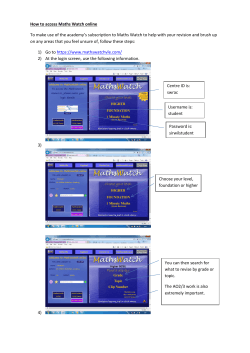


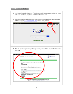

© Copyright 2026