
Document 313194
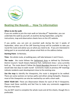
PSC REF#:158960
CHAPTER
4
4. Mississippi River at Alma to
Holmen—Detailed Project Description
4.1. PROPOSED 345 KV TRANSMISSION LINE ROUTE
ALTERNATIVES
T
he applicants have proposed three routes, with some variations, to make the connection from the
Mississippi River crossing at Alma in Buffalo County to a new substation in the La Crosse service
area near the village of Holmen in La Crosse County. The routes can be traced by route segments
on the Index map in Figure Vol. 2-1 or on the existing electric transmission facilities map in Figure
Vol. 2-2. Each route is described in terms of its individual route segments at the beginning of the EIS
chapter dedicated to a discussion of its potential impacts (Chapters 7 through 11). The routes are
described more briefly below to establish some perspective for the discussions that follow in this chapter.
4.1.1.
Q1-Highway 35 Route and Q1-Galesville Route
Two of the routes, the applicants’ Q1-Highway 35 and Q1-Galesville Routes, follow an existing 161 kV
corridor southward as a 345/161 kV double-circuit line on metal, single-pole structures along the
GRRNSB to the mouth of Waumandee Creek between the villages of Cochrane and Fountain City. At
that point the routes leave the Mississippi River and extend inland, still following the existing 161 kV
corridor as a double-circuit line. East of the Trempealeau River, these two routes diverge and follow very
different paths to avoid different resource impacts. The routes are discussed in detail in Chapters 7 and 8,
respectively.
The Q1-Highway 35 Route continues along the existing 161 kV transmission corridor as a double-circuit
line to where the corridor intersects with STH 35 east of the village of Trempealeau. From that point, the
route leaves the 161 kV corridor, takes the 161 kV line with it, and parallels STH 35 east as a double-circuit
line across the Black River bottomlands and the Van Loon State Wildlife Area to the STH 35/USH 53
interchange, where it then follows USH 53 southward to a proposed substation site along Briggs Road
southwest of Holmen. This route was proposed by the applicants as an alternative to their original
proposal that followed the existing Q1 transmission corridor all the way to the substation site. The
existing Q1 corridor in this area passes through the Refuge, and the USFWS has indicated that it would
not support that corridor.
The Q1-Galesville Route avoids the Black River bottomlands and the Van Loon Wildlife Area by
diverging from the existing 161 kV corridor around Delaney Road east of the Trempealeau River and
running eastward as a single-circuit line, connecting with STH 54 south of Galesville and intersecting with
a different, north-south 161 kV transmission corridor east of USH 53. From that point, it follows the
transmission corridor, USH 53, CTH HD, and Briggs Road as a double-circuit line to the proposed
substation site.
36
CHAPTER 4 – MISSISSIPPI RIVER AT ALMA TO HOLMEN – DETAILED PROJECT DESCRIPTION
Public Service Commission of Wisconsin
RECEIVED: 02/01/12, 1:22:50 PM
P U B L I C S E R V I C E C O M M I S S I O N O F W I S C O N S I N
D E P A R T M E N T O F N A T U R A L R E S O U R C E S
P U B L I C
4.1.2.
S E R V I C E C O M M I S S I O N O F W I S C O N S I N
D E P A R T M E N T O F N A T U R A L R E S O U R C E S
WisDOT’s STH 88 Connector Alternative for the Q1 Routes
WisDOT has strong concerns about a route along the GRRNSB (STH 35), and has suggested an
alternative route connector that would run from the Mississippi River crossing at Alma east as a
345/161 double-circuit line to a point north of Waumandee Creek valley and south along STH 88 as a
single-circuit line to connect to the Q1-Highway 35 or Q1-Galesville Route from the north. From
Waumandee Creek eastward, either of the two Q1 Routes would be the same. Commission staff has
included this route connector alternative in its review so that it can be considered by the Commission
when making final project decisions. It is discussed in Chapter 9 of this final EIS.
4.1.3.
Arcadia Route
A third route proposed by the applicants avoids the GRRNSB and the Van Loon Wildlife Area almost
entirely. It is an overland route that, from Alma, roughly follows the existing east-west 161 kV
transmission corridor over the river bluffs as a 345/161 kV double-circuit line to a point across the
Trempealeau River northeast of Arcadia. It then turns south following an existing north-south 69 kV
transmission corridor generally as a 345/69 kV double-circuit line to STH 54 east of Centerville, and then
heads east on STH 54 and south of Galesville along the identical path for the Q1-Galesville Route to the
substation. The Arcadia Route is discussed in Chapter 10 of this final EIS.
4.1.4.
Ettrick Connector Alternative for the Arcadia Route
WDNR staff suggested that an alternative route might be found that would provide the Commission with
a second routing possibility to avoid the Black River bottomlands and the Van Loon State Wildlife Area.
The applicants responded with this alternative, which diverges from the Arcadia Route where the existing
69 kV corridor crosses Fox Coulee Lane. It follows an east-west 69 kV corridor as a 345/69 kV
double-circuit line (with the 69 kV portion built to 161 kV standards) along Fox Coulee and Hovell Lane,
and across a ridge. It continues to follow the 69 kV corridor eastward into the Beaver Creek valley to
where the 69 kV meets the existing north-south 161 kV corridor west of the village of Ettrick. It follows
that 161 kV corridor southward to the Black River and, from there, follows the same path as the Arcadia
or Q1-Galesville Routes to the proposed substation site. The Ettrick Alternative is discussed in Chapter
11 of this final EIS.
4.1.5.
Applicants’ original Q1 Route
During the pre-application process, the applicants proposed a route following the existing DPC 161 kV
line between Alma and the North La Crosse Substation in Holmen called the Q1 line. This line is reaching
the end of its service life, and DPC has determined that it needs to be rebuilt or replaced. Portions of the
original Q1 Route were eliminated in the CPCN application because the USFWS indicated it would not
want to permit the portion of it that crosses the Refuge. In case circumstances surrounding the project
changed, comparable information was provided about this route in the draft EIS so that, if the
Commission determined that it should be considered, it could make informed decisions. 85 Potential
impacts of the original Q1 Route are discussed in Chapter 7, the chapter about the Q1-Highway 35 Route,
where appropriate. In its comments on the draft EIS, USFWS stated outright that “expansion of the
expired right-of-way to accommodate a rebuild of the 161 kV line and the new 345 kV line should not be
85
The information was provided in the CPCN application as Appendix N.
CHAPTER 4 – MISSISSIPPI RIVER AT ALMA TO HOLMEN – DETAILED PROJECT DESCRIPTION
37
P U B L I C S E R V I C E C O M M I S S I O N O F W I S C O N S I N
D E P A R T M E N T O F N A T U R A L R E S O U R C E S
considered as a viable alternative.” 86 Therefore, although the route information remains in this final EIS,
the original Q1 Route should be dropped from consideration.
4.1.6.
Blair Route
In its comments on the draft EIS, the USFWS recommended that the “Blair option be fully analyzed” in
the final EIS. Some individual commenters have asked for this analysis as well. The Blair Route had
already been removed from consideration by the applicants and Commission staff during the
pre-application process for this docket. It shared too much ROW with the eventually-proposed Arcadia
Route, added about 5.0 miles beyond the Arcadia Route, and added costs as well. It is not under
consideration in this docket or this EIS.
4.1.7.
Bluff Route
A suggestion was made during the draft EIS comment period to analyze more fully an early route option
called the “Bluff Route.” This option would have the new line climb the bluff at Alma and run
cross-country along the bluff tops outside of the Mississippi River Valley and the corridor of the
GRRNSB. This route was removed from consideration by the applicants and Commission staff during
the pre-application process because it created all new impacts on woodlands and farmlands when there
already were viable routes down the river valley and eastward to Arcadia. It is not under consideration in
this docket or this EIS.
4.2. ELECTRIC TRANSMISSION FACILITIES
4.2.1.
Transmission line facilities
4.2.1.1. Voltage
The proposed new transmission line would be energized at 345 kV. Existing 161 kV and 69 kV lines in
the selected route corridors would be removed and reconstructed at their existing voltages in a double- or
triple-circuit with the new 345 kV transmission line.
4.2.1.2. Size of conductors
The 345 kV transmission line would have bundled (two) 954 kcmil 45/7 Cardinal aluminum conductor
steel supported (ACSS) or 954 ACSS/TW Cardinal 20/7 Type 13 conductors per phase. There are three
phases in a transmission line, so there would be three sets of bundled conductors.
The reconstructed 161 kV circuits would have a single 795 kcmil 26/7 Drake ACSS conductor per phase,
and reconstructed 69 kV circuits would have a single 795 kcmil 26/7 Drake ACSS conductor per phase.
Again, each type of transmission line would consist of three conductors (three phases).
4.2.1.3. Size of shield wire
The new 345 kV transmission line with and without reconstructed circuits of 161 kV and 69 kV of would
use two shield wires to protect phase conductors from lightning strikes. The shield wires would consist of
standard 7/16-inch, seven-strand extra high-strength steel cable and/or a steel and aluminum stranded
wire containing a fiber optic bundle core, generally known as optical ground wire (OPGW). OPGW
86 Letter from Tony Sullins, USFWS, to William Fannucchi of Commission staff with comments on the draft EIS. December 22, 2011.
PSCW REF #157730.
38
CHAPTER 4 – MISSISSIPPI RIVER AT ALMA TO HOLMEN – DETAILED PROJECT DESCRIPTION
P U B L I C
S E R V I C E C O M M I S S I O N O F W I S C O N S I N
D E P A R T M E N T O F N A T U R A L R E S O U R C E S
allows both lightning protection and a communication path between substations. The OPGW would
include 36 to 48 fibers.
4.2.1.4. Structure types and heights
The applicants would use galvanized and brown, self-weathering steel poles to try to reduce visual effects
along the GRRNSB. In other route sections, the applicants would use primarily single-pole, brown,
self-weathering steel structures placed on reinforced concrete foundations. Tangent poles, with arms out
to the sides, would carry the line on straightaways. Angle poles, with arms at different angles from the
perpendicular, would support the line where it turns at slight angles from a straight path. Two-pole
structures (H-frame) and other multiple-pole structures would be used for transmission line alignment
angles greater than 30 degrees, for reducing foundation size, for crossing wetlands, and for allowing long
spans between hilltops in difficult terrain, such as the hilly coulee regions or river crossings.
Structure diameters at the structure base would vary from five to seven feet if single-pole structures were
used and between five and eight feet at two-pole situations. Structure heights above ground would range
from 130 to 185 feet. The applicants have proposed alternate designs in response to concerns raised by
agencies, including reduced heights at crossings of the Trempealeau and Black Rivers.
The 345, 161, and 69 kV transmission line conductors would be supported by porcelain or glass I-String
and V-String insulators on tangent (straight line) and angle poles and by double-string insulators on
dead-end poles.
Diagrams of the expected typical structure types were prepared by the utilities for their application and can
be found in Appendix A of this final EIS for the reader’s convenience. Appendix A includes tables that
relate structure types to proposed route segments. The diagrams show general structure characteristics
and conductor support configurations. Pole or structure types expected to be used for different routes are
identified below.
•
•
•
•
•
Q1-Highway 35 Route – Appendix A, Figures 1 through 19 and 30
Q1-Galesville Route – Appendix A, Figures 1-24 and 26-29
Q1-STH 88 Connector Alternative, Option A – Appendix A, Figures 3, 5, 7, 8, 10, 21, 23, 25,
and 27
Q1-STH 88 Connector Alternative, Option B – Appendix A, Figures 3, 5, 7, 8, 10, 21, 23, 25,
27, and 28
Arcadia-Ettrick Connector Alternative – Appendix A, Figures 1-8, 11-12, 17, and 18
4.2.1.5. Foundations
Most of the transmission poles would be installed on steel-reinforced, concrete foundations. The
foundations would be drilled pier concrete foundations varying from 6 to 10 feet in diameter and about
25 to 50 feet deep, depending on soil conditions. General foundation installation steps are described in
Section 5.4.3 and 5.4.4 of Chapter 5 of this final EIS. Example illustrations of foundation construction
work can be found in the following Figures in Volume 2 of the final EIS:
•
•
•
Vol. 2-19, 2-21, and 2-24 for drilling/augering the hole
Vol. 2-25-28 for installing the foundation
Vol. 2-30, 2-31, and 2-32 for installing the structure on the foundation
CHAPTER 4 – MISSISSIPPI RIVER AT ALMA TO HOLMEN – DETAILED PROJECT DESCRIPTION
39
P U B L I C S E R V I C E C O M M I S S I O N O F W I S C O N S I N
D E P A R T M E N T O F N A T U R A L R E S O U R C E S
If the Q1-Highway 35 Route through the Black River floodplain is approved (Segment 8B), or the original
Q1 segment through the Black River floodplain is revisited (Segment 5B), tubular vibratory caisson
foundations would be employed. In this design, a steel caisson is stood up at the pole location, and a
vibratory hammer is put on top of the caisson. The heavy hammer vibrates and drives the caisson into the
ground until its top is about 2 to 3 feet above ground level and its depth is about 30 to 70 feet below
grade. There would be no concrete poured or excavation spoils. The transmission structures would be
installed on the tops of the caissons.
All construction materials, equipment, and labor would be brought to remote foundation sites over
temporary access roads, using special matting where required to protect underlying soils and vegetation.
In some wetland cases, the materials and equipment would be brought to the foundation site by heavy-lift
helicopter. The helicopter would also stand up the caisson at its pole location, attach the vibratory
hammer, and remove the heavy equipment when the job was complete.
Some of the structures in the Mississippi River crossing (Segment 1) might require a “cap-on-pile”
foundation design, employing piles driven into the river bottom with pile caps installed on the tops of
supporting piles and the transmission structures installed on the pile caps.
4.2.1.6. Span length and conductor clearances
The span length (the distance between structures) would typically vary from 700 to 1,000 feet, depending
on the feature that needs to be spanned. Conductor heights along the line would vary, with the minimum
height at mid-span about 34 feet above ground. The mid-span conductor height would be highly variable
because of topography. Generally, conductor height would vary between 35 and 50 feet above ground
level.
4.2.2.
Rights-of-way
4.2.2.1.
Relationship between ROW, structure type and height, and span
length
An electric transmission line ROW is a strip of land that an electric utility uses to construct, maintain, or
repair a large power line. A transmission line is usually centered in the ROW. The structures (usually
poles and cross arms) keep the wires away from the ground, other objects, and each other. Structure
height, structure type, span length, and ROW width are interrelated. If landowners wish to have fewer
transmission structures installed on their land, they might ask if a longer span length is possible. To
increase the span length, the utility might need to increase the structure height. If the span length and
height are greatly increased, a wider ROW is sometimes needed.
The proposed transmission line would require a ROW wide enough to keep the conductors safely distant
from buildings, trees, the ground, and other features as they hang between the transmission poles or other
structures. It would also require a ROW wide enough for the equipment and working area to construct
the line. The construction ROW, part of which might be temporary, might be wider than the permanent
safety clearance ROW. An easement agreement for a ROW would allow the utility to keep the line clear of
vegetation, buildings, and other structures that could interfere with line operation. It would also allow the
landowner certain land use controls and conditions. If they are needed, the utility might also obtain
easements for access roads to get to the power line ROW.
4.2.2.2. ROW for Alma-La Crosse project
The CapX applicants say that the typical required ROW width, with some exceptions, would be 150 feet.
In some instances, to preserve tree buffers or for other reasons, the total ROW wanted by the applicants
40
CHAPTER 4 – MISSISSIPPI RIVER AT ALMA TO HOLMEN – DETAILED PROJECT DESCRIPTION
P U B L I C
S E R V I C E C O M M I S S I O N O F W I S C O N S I N
D E P A R T M E N T O F N A T U R A L R E S O U R C E S
might be less than the 150-foot norm. An example would be near the city of Alma near STH 35, where
the ROW would be reduced to 115 feet to preserve a screen of trees to reduce visual impacts. In other
situations, because of longer spans or unique circumstances, a ROW greater than 150 feet might be
needed.
In some locations, the ROW would be shared in part with other, already existing transmission ROWs, or
road or railroad ROWs. Overall, according to the project CPCN application and depending on the route,
the additional ROW width needed could vary from zero to 150 feet. 87 For example, the entire 150 feet
would be needed if there is no existing ROW to share. Existing 161 and 69 kV transmission lines already
in the project area have ROWs of about 80 feet, so an additional 70 would be needed for the new line.
Road ROW widths vary, but typical highway ROWs that could be involved in this project share about
70 feet of ROW width, leaving about 80 feet that would be needed for the new line. South of Galesville,
there is a place where the new line would be entirely within road ROW so no additional ROW would be
sought.
If the required conductor clearances occur over highway ROW, easements cannot be purchased. Instead,
the applicants must obtain a permit from WisDOT. The permit would limit WisDOT from planting
vegetation, constructing sound barriers, or having unhindered use of the airspace above the ROW where
the conductors would hang. The permit would also require the applicants to clear vegetation as necessary
to maintain required clearances.
ROW requirements are covered in the discussions of potential environmental impacts for the individual
routes in Chapters 7 through 11.
4.2.2.3. Utility ROW clearing
Since the ROW must be kept clear to maintain safe distances for the conductors, some vegetation removal
would occur once the ROW easement agreement was made. The Commission requires Wisconsin utilities
to maintain their ROWs and clearances in accordance with the National Electric Safety Code (NESC).
The NESC requirements are incorporated into Wis. Admin. Code ch. PSC 114.
NESC generally requires the pruning or removal of interfering trees to minimize the risk of
vegetation-related outages. Otherwise, there are increased chances of fires or electrical or mechanical
damage to the electrical equipment. Xcel (and NSPW) has a published guide on ROW vegetation
management 88 that includes lists and diagrams illustrating the types of clearances or removals that would
need to be maintained. Figure 4.2-1 illustrates a typical transmission line ROW requirement.
87 CPCN Application, Appendix A, Tables 1A for the Q1-Highway 35, Q1-Galesville, and Arcadia Routes, and Appendix W-A, Tables 1A
for the STH 88 Connector Options and Arcadia-Ettrick Connector.
88 Xcel Energy. Vegetation Management Guidelines. May 2011.
CHAPTER 4 – MISSISSIPPI RIVER AT ALMA TO HOLMEN – DETAILED PROJECT DESCRIPTION
41
P U B L I C S E R V I C E C O M M I S S I O N O F W I S C O N S I N
D E P A R T M E N T O F N A T U R A L R E S O U R C E S
Figure 4.2-1
Typical Xcel/NSPW ROW clearing requirements
Xcel maintains a “wire zone/border zone” concept for its vegetation management program to allow for
different types and heights of vegetation in the ROW. The wire zone in the Xcel policy is the area directly
beneath the conductors, as can be seen in Figure 4.2-1. The vegetation allowed in the wire zone would be
low-growing herbaceous communities. Other plants would be removed. The border zone would begin at
the outside edge of the wire zone and extend to the edge of the ROW as defined in the easement
agreement. This zone may contain low-growing woody plants and trees. In the wire zone and border
zone, Xcel states that it “does not require removal of tall-growing trees if, at maximum mature height, the
tree would not come within the distances set forth in the Minimum Clearance Guidelines, even if the tree
were to fall toward the conductors.” 89
Outside the border zone, there are still potential hazards to the line. “Danger trees” would include any
trees on or off the ROW that have the potential to contact the line. “Hazard trees” would be danger trees
that have “unacceptable risk” of failing before the next maintenance cycle. They would be topped,
pruned, or felled when identified so that they were no longer hazards. Example hazard tree clearing areas
are illustrated in Figure 4.2-1 as well.
4.3. PROJECT ENDPOINT—MISSISSIPPI RIVER CROSSING
The Wisconsin CapX project’s western terminus would be a mid-river connection with the Mississippi
River crossing for the Minnesota CapX project.
Over the development of the project proposal, the applicants investigated several different places for the
proposed transmission line to cross the Mississippi River between Minnesota and Wisconsin and connect
with the Wisconsin electric systems. They informed the Commission and WDNR of these alternatives
during the pre-application process for the case. Two alternatives, at Winona and Trempealeau, were
89 Xcel Energy. Vegetative Management Guidelines. May 2011, p. 12.
42
CHAPTER 4 – MISSISSIPPI RIVER AT ALMA TO HOLMEN – DETAILED PROJECT DESCRIPTION
P U B L I C
S E R V I C E C O M M I S S I O N O F W I S C O N S I N
D E P A R T M E N T O F N A T U R A L R E S O U R C E S
dropped from consideration before the pre-application process at the Commission was significantly
underway.
4.3.1.
Alternative crossings and interconnections
Four potential river crossing locations were identified:
•
•
•
•
Between La Crescent, Minnesota, and La Crosse, Wisconsin, where an existing transmission line
crosses the river. That line operates at 69 kV but is built to 161 kV standards. See Figures Vol.
2-7D, Vol. 2-11, and Vol. 2-12.
Near Trempealeau, Wisconsin, at Lock and Dam No. 6. There is no existing transmission line
there, but the crossing might have been workable because it is a narrow point in the river that
includes several islands on which transmission structures could be located. See Figure Vol. 2-7C.
At Winona, Minnesota, where a 69 kV line built to 161 kV standards exists already. See Figures
Vol. 2-7B and Vol. 2-10.
At Alma, Wisconsin, where an existing 161/69 kV double-circuit line already crosses the river
south of the DPC generating stations. See Figures Vol. 2-7A, Vol. 2-8, and Vol. 2-9. The Alma
crossing is identified in the Wisconsin CapX project as Segment 1.
Crossings at any other places along the river between Alma and La Crosse would require totally new
transmission ROW and a completely new feature crossing the river where no existing river-crossing
features exist. There is no need to consider such crossing locations because at least one of the above four
locations appears workable.
4.3.2.
Winnowing of crossing alternatives
By the time the project CPCN application was submitted to the Commission, the four alternatives had
been narrowed to one, at Alma. Decisions to drop certain alternative crossings were based on input from
USFWS and WDNR.
The applicants eliminated the Trempealeau crossing early in the consideration because it would require a
new transmission ROW crossing the Refuge. It was the only crossing of the four that did not have an
existing electric transmission ROW. USFWS said it would likely not approve a Special Use Permit for new
ROW across the Refuge because USFWS regulations do not allow new uses of Refuge property that
fragment habitat. 90 USFWS also raised concerns about migratory birds in the Trempealeau National
Wildlife Refuge. The applicants also decided to avoid numerous residences along the river on the
Wisconsin side.
The applicants also eliminated the Winona crossing early in the process. The existing transmission line
had a 100-foot ROW permitted by USFWS. However, USFWS did not want the additional construction
that would be necessary in the Refuge at that location, for the same reasons it delineated for the
Trempealeau crossing. The existing crossing at Winona was relatively long, passed through the Refuge,
and entered Wisconsin at the mouth of the Trempealeau River by the GRRNSB. The potential
environmental impact was greater relative to the other two crossings and this crossing was eliminated from
the analysis.
The crossing between La Crosse and La Crescent is a shorter crossing and would require a small amount
of 345 kV transmission to be built. USFWS described it as its second choice after the Alma crossing, with
90
Letter to Pamela Rasmussen of Xcel from Don Hultman of USFWS. February 19, 2008. CPCN Application, Appendix P, p. 21.
CHAPTER 4 – MISSISSIPPI RIVER AT ALMA TO HOLMEN – DETAILED PROJECT DESCRIPTION
43
P U B L I C S E R V I C E C O M M I S S I O N O F W I S C O N S I N
D E P A R T M E N T O F N A T U R A L R E S O U R C E S
reservations. 91 However, the substation that would be the endpoint of the line (Xcel’s La Crosse
Substation) is at the edge of the La Crosse Marsh Natural Resource Area, a 1,077-acre urban wetland
complex. An expansion into this marsh, or installation of transmission towers in or around it, would have
a large environmental impact on the functions and values of the wetlands. According to WDNR staff, the
substation is within the La Crosse River floodway or flood fringe, and a portion of the projected
transmission route to it would have to cross property acquired by WDNR. WDNR indicated that the
wetland construction in this situation would have “the possibility of being un-permittable.” 92 An attempt
to site an endpoint substation in another part of the city or on the uplands east of the city appeared to
require construction in city streets and the relocations of certain businesses as well as an environmentally
sound and feasible way up the bluff.
The applicants propose the Alma crossing. It requires less steep river bluff terrain construction on the
Minnesota side and follows an existing transmission corridor. It would also require the shortest crossing
of the Mississippi River floodplain and the Refuge and have fewer wetland impacts. And, it is the crossing
preferred by USFWS, 93 which identified the Alma crossing as the one that “may pose the least
environmental impact.” 94
During the pre-application process for this PSCW docket, the crossings had been winnowed to two, at La
Crosse or at Alma. Because of the problems discussed above with the La Crosse crossing, Wisconsin and
Minnesota agency staff decided to concentrate on the Alma crossing as the place where the two portions
of the CapX2020 project proposal would meet. Unless the Minnesota OES determined after its EIS
scoping process that the La Crosse crossing should be carried forward in the process or the Alma crossing
was not viable, then the scope of the Minnesota EIS would include the Alma crossing as the only crossing.
The Wisconsin CPCN process would then concentrate on the project with the Alma crossing as one end
point. The Minnesota OES scoping decision in August 2010 confirmed the Alma crossing as the one to
be carried through the two states’ review processes. See Appendix D, the Executive Summary of the
Minnesota EIS, page 1. 95 This is the crossing being used in the Wisconsin process as an endpoint.
4.3.3.
Crossing at Alma
The applicants have developed Alma crossing designs with different tradeoffs between structure height
and ROW width in consultation with USFWS.
An existing double-circuit transmission line crosses the Mississippi River and about 0.5 mile of the Refuge,
with two structures on Refuge property on a 180-foot-wide permitted ROW. The two main structures
supporting the river crossing are 180 feet tall. An area about 125 feet wide is kept clear of trees.
Minimum conductor clearance over the main channel of the river is about 90 feet, as required by USACE.
To accommodate a new 345 kV line, a triple-circuit system would be needed. 96 If it remained within the
existing 125-foot cleared ROW, the structures supporting the main channel crossing would need to be
about 275 feet tall and could be required by the Federal Aviation Administration (FAA) to be painted red
Rassmussen letter from Hultman, p. 20.
Letter to Tom Hillstrom of Xcel Energy from Cheryl Laatsch and Shari Koslowsky of WDNR. May 29, 2009. CPCN Application,
Appendix P, pp. 124-125.
93 CPCN Application, Introduction and Overview, pp. 1-15.
94 Rasmussen letter from Hultman, p. 20.
95 Section 6 of the Minnesota OES EIS discusses the factors supporting the “Kellogg Crossing” at Alma in detail. It also discusses
alternative crossing methods. CapX Hampton-Rochester-La Crosse 345 kV and 161 kV Transmission Lines Project Environmental
Impact Statement, August 2011.
96 The options for the line across the Mississippi River at Alma are discussed, mapped, and diagrammed in detail in the CPCN Application,
Appendix F2. An example triple-circuit structure can be seen in Appendix A, Figure 14 of this EIS. The exact structure heights and ROW
widths for the river crossing would be subject to USFWS permitting.
91
92
44
CHAPTER 4 – MISSISSIPPI RIVER AT ALMA TO HOLMEN – DETAILED PROJECT DESCRIPTION
P U B L I C
S E R V I C E C O M M I S S I O N O F W I S C O N S I N
D E P A R T M E N T O F N A T U R A L R E S O U R C E S
and white. Other options keep the structures at the main channel as short as possible, just under 200 feet
tall, and all the conductors on the lines in the same plane to minimize bird impacts. One such option
would require the cleared ROW to be expanded up to about 280 feet. Others would keep the main
channel-crossing structures below 200 feet but utilize different combinations of structure designs for the
other seven structures (four in the Wisconsin portion) that allow cleared ROWs to be narrower, back to
about 125 feet near the Minnesota and Wisconsin shore. One option would keep the cleared ROW at the
main channel at about 180 feet, with about 125 feet of width toward either shore. Because a Special Use
Permit would be required to cross the Refuge, the applicants would work closely with USFWS to identify
the most appropriate structure design for crossing the river with an overhead line.
On USFWS request, an underground alternative was investigated, either an extruded dielectric cable
system or a high-pressure fluid-filled (HPFF) pipe. Both underground options would avoid bird collision
impacts across the river. On the other hand, both options would require direct bore or trenching
installation. An open trench method would disrupt the river and its bed across its entire width. A direct
bore method would avoid a long open trench but would require about eight ten-inch borings under the
river spaced about 25 feet apart. There would be additional tree clearing for construction areas. The
existing lines on overhead structures would remain in place, continuing to present an obstacle to bird
flight. And, a new overhead transition station about an acre in size between the underground and
overhead construction would be needed at each end of the underground segment. In the case of the
HPFF, there would be additional environmental risk related to the mineral oil dielectric coolant in the
pipes. For the limited protection of birds and the additional impact at the ground level and underwater,
the underground options would also be more expensive, about $90 million for 1.3 miles of construction or
$70 million per mile as opposed to about $2 million per mile for overhead construction. 97
4.4. PROJECT ENDPOINT—BRIGGS ROAD SUBSTATION
The eastern endpoint of the Alma-La Crosse Project would be a 345/161 kV substation southwest of
Holmen in La Crosse County. The substation, its proposed alternative sites, and potential environmental
impacts are discussed in more detail in Chapter 6.
4.4.1.
Proposed facilities description
A new 345/161 kV transmission substation called the Briggs Road Substation would be constructed as
part of the project. This substation would allow the new 345 kV transmission line to connect to the
existing transmission lines in the La Crosse area. It would be owned and operated by NSPW.
4.4.2.
Location
The new Briggs Road Substation would be constructed near the intersection of USH 53 and Briggs Road
in the town of Onalaska, near Holmen, at the southern end of the project area. The applicants have
identified two potential substation sites on either side of Briggs Road, a West Site and an East Site.
4.4.3.
Existing environment
The West Site supports field crops. There is recreational area with woodlands and wetlands within 0.5
mile south of the West Site. Within 0.5 mile to the north, there is open space and single-family homes,
with USH 53 physically separating the proposed Briggs Road Substation West Site from the open space
and the houses. There is also woodland and wetland 0.5 mile to the east.
97
Underground Feasibility Analysis – Alma Crossing: Applicants’ Conclusions. CPCN Application, Appendix F3.
CHAPTER 4 – MISSISSIPPI RIVER AT ALMA TO HOLMEN – DETAILED PROJECT DESCRIPTION
45
P U B L I C S E R V I C E C O M M I S S I O N O F W I S C O N S I N
D E P A R T M E N T O F N A T U R A L R E S O U R C E S
The nearby East Site currently supports horse farm facilities, including an exhibition area and pastures,
with woodlands at the south and east ends. Land use within 0.5 mile south of the East Site is active
agriculture and rural residential. Land use within 0.5 mile west of it is agricultural land and woodland.
Within 0.5 mile north of it are single-family homes and the North La Crosse Substation. Again, USH 53
would physically separate the proposed substation from the residential and recreation lands to the north.
Land use to the east of the proposed site is woodland.
4.4.4.
Acreages and heights of existing and new construction
The general substation arrangement is shown in Figure 4.4-1, at the Briggs Road West Site as an example.
Figure 4.4-1
General substation facilities arrangement at Briggs Road West Site Alternative
For the West Site, initial construction of the substation area would occupy approximately 10 acres. The
ultimate layout would require an additional two acres for future expansion. NSPW would purchase
approximately 40 acres overall.
The East Site would be located on a 70-acre parcel of land east of Briggs Road. If the Commission selects
this site, NSPW would acquire 40 acres of this parcel and construct the proposed substation on
approximately 10 acres allowing for future expansion as well.
46
CHAPTER 4 – MISSISSIPPI RIVER AT ALMA TO HOLMEN – DETAILED PROJECT DESCRIPTION
P U B L I C
S E R V I C E C O M M I S S I O N O F W I S C O N S I N
D E P A R T M E N T O F N A T U R A L R E S O U R C E S
The highest structure on the substation site would be would be 105 feet tall. This structure would support
the entry of the 345 kV transmission line into the substation. Structures supporting the entry of the
161 kV transmission lines would be about 75 feet tall. Other structures would be much lower in height.
No landscaping is anticipated at the proposed East or West Sites.
4.5. COSTS
The proposed project costs estimated as the sum of year-of-occurrence dollars range from about
$195 million to about $234 million, depending upon the transmission line route. These costs were
estimated from 2010 dollar costs and escalated to represent 2014-2015 construction years using the
industry-recognized Handy-Whitman index. They include the new substation cost, distribution line
relocation cost, and allowance for funds used during construction (AFUDC).
The details of these costs are shown in Tables 4.5-1, 4.5-2, and 4.5-3.
4.5.1.
New substation
The Briggs Road Substation is common to all routing alternatives. Table 4.5-1 shows costs to construct
the Briggs Road Substation. The total substation cost, $27,285,000, is shown in the lower right corner of
the table.
Table 4.5-1 98
Briggs Road Substation construction cost estimates
Project Cost Categories
Engineering and Design
Material
Transformer
Construction Labor and Rents
Commissioning and Testing
Other
Total Substation Cost
4.5.2.
345 kV portion
$234,000
$1,914,000
0
$1,267,000
$100,000
$1,318,000
$4,833,000
161 kV portion
$936,000
$7,656,000
$3,870,000
$5,068,000
$400,000
$4,522,000
$22,452,000
Total
$1,170,000
$9,570,000
$3,870,000
$6,335,000
$500,000
$5,840,000
$27,285,000
Utility-proposed routes
The applicants proposed three alternative routes and one alternative segment. The costs provided by the
applicants are itemized in Table 4.5-2. The cost of the Briggs Road Substation has been factored into each
of the alternative route costs.
98
From CPCN Application, pp. 2-62.
CHAPTER 4 – MISSISSIPPI RIVER AT ALMA TO HOLMEN – DETAILED PROJECT DESCRIPTION
47
P U B L I C S E R V I C E C O M M I S S I O N O F W I S C O N S I N
D E P A R T M E N T O F N A T U R A L R E S O U R C E S
Table 4.5-2
Project cost estimates for utility-proposed transmission routes plus the proposed Briggs Road Substation 99
Project Cost Categories
Material
Poles
Wire
Other Material
Labor
ROW Prep
Foundations
Line
Other
Real Estate
Technical Support Services
Environmental
Removal
Distribution Relocations
Escalation
Overheads
AFUDC
Subtotal
Substation
Briggs Road Substation
161 kV re-routes to substation
Material
Labor
Other
Subtotal
Other Costs
Pre-certification Costs
One-Time Environmental Impact Fee*
Annual Impact Fees Based on Three
Years to Construct the Project*
Subtotal
Total Cost
Q1–Highway 35
Route
Arcadia Route
Alma-Arcadia
Option 100
Q1-Galesville
Route
$22,680,000
5,440,000
15,040,000
$28,410,000
5,910,000
16,220,000
$28,190,000
5,830,000
16,070,000
$24,270,000
5,640,000
13,780,000
2,620,000
16,970,000
19,980,000
2,570,000
22,470,000
23,620,000
2,490,000
21,980,000
23,460,000
2,380,000
19,180,000
21,180,000
3,860,000
13,010,000
1,410,000
2,020,000
0
18,410,000
6,970,000
19,330,000
$147,740,000
4,940,000
13,370,000
1,470,000
2,070,000
2,820,000
22,190,000
8,370,000
22,960,000
$177,390,000
4,890,000
13,350,000
1,470,000
2,050,000
2,820,000
21,960,000
8,290,000
22,740,000
$175,590,000
4,360,000
13,190,000
1,440,000
1,890,000
1,820,000
19,470,000
7,340,000
20,400,000
$156,340,000
$27,285,000
$27,285,000
$27,285,000
$27,285,000
$946,000
1,496,000
1,871,000
$31,598,000
$562,000
868,000
1,102,000
$29,817,000
$562,000
868,000
1,102,000
$29,817,000
$562,000
868,000
1,102,000
$29,817,000
$7,281,000
$7,117,000
$7,686,000
$8,448,000
$7,668,000
$8,558,000
$7,476,000
$7,528,000
$854,000
$1,014,000
$1,026,000
$904,000
$15,192,000
$17,148,000
$17,252,000
$15,908,000
$194,590,000
$224,355,000
$222,659,000
$202,065,000
* The Commission determined in the Rockdale-West Middleton 345 kV case (PSCW docket 137-CE-147) that pre-certification costs would
not be included in the cost basis calculation for high-voltage impact fees. The Commission will need to determine in this case if non-345 kV
construction costs should be included in the cost basis calculation for the high-voltage impact fees. See discussion in Section 4.5.4.
4.5.3.
Routes resulting from WisDOT and WDNR requests
In this section, costs are provided for alternative routes that are being considered based on requests made
by WisDOT and WDNR.
Variations on the Q1-Highway 35 and Q1-Galesville Routes were proposed by WisDOT to provide
alternatives that would avoid route segments along STH 35 (GRRNSB), between Alma and the mouth of
From CPCN Application, pp. 2-60 and 2-61.
This option is the Arcadia Route using a different route segment (10B2) to connect the line at the river with the existing 161 kV ROW
east of the bluffs at Alma.
99
100
48
CHAPTER 4 – MISSISSIPPI RIVER AT ALMA TO HOLMEN – DETAILED PROJECT DESCRIPTION
P U B L I C
S E R V I C E C O M M I S S I O N O F W I S C O N S I N
D E P A R T M E N T O F N A T U R A L R E S O U R C E S
Waumandee Creek. The alternatives would utilize the Waumandee Creek valley along STH 88. Because
STH 88 is very curvy the applicants provided costs not only for route segments along the highway but also
for route segments in the valley that appeared better from engineering and environmental points of view.
(See route discussions earlier in this chapter.) Table 4.5-3 shows cost breakdowns for each option in each
of the two Q1 Routes.
A variation on the Arcadia Route was developed by the applicants in response to a request from WDNR
that a transmission ROW be followed toward Ettrick north of the Van Loon Wildlife Area. The costs for
the Arcadia-Ettrick alternative are also included in Table 4.5-3.
Table 4.5-3
Project cost estimates for STH 88 and Ettrick Route Alternatives based on requests from WisDOT and
WDNR, plus the proposed Briggs Road Substation 101
Project Cost Categories
Material
Poles
Wire
Other Material
Labor
ROW Prep
Foundations
Line
Other
Real Estate
Technical Support Services
Environmental
Removal
Distribution Relocations
Escalation
Overheads
AFUDC
Subtotal
Substation
Briggs Road Substation
161 kV Re-routes to Substation
Material
Labor
Other
Subtotal
Other Costs
Pre-certification Costs
One-time Environmental
Impact Fee*
101
WI-88
Option A
Connector
(Q1-Highway
35) Route
WI-88
Option A
Connector
(Q1-Galesville)
Route
WI-88
Option B
Connector
(Q1-Highway
35) Route
WI-88
Option B
Connector
(Q1-Galesville)
Route
Arcadia-Ettrick
(Arcadia)
Route
$25,300,000
$5,660,000
$17,062,000
$26,890,000
$5,850,000
$15,772,000
$24,560,000
$5,590,000
$16,461,000
$26,150,000
$5,780,000
$15,179,000
$28,890,000
$6,380,000
$17,386,000
$2,920,000
$22,170,000
$21,100,000
$2,660,000
$24,240,000
$22,150,000
$3,150,000
$20,430,000
$20,750,000
$2,880,000
$22,490,000
$21,800,000
$2,990,000
$27,230,000
$24,690,000
$4,470,000
$12,700,000
$1,440,000
$1,750,000
$1,060,000
$20,560,000
$7,770,000
$21,280,000
$165,242,000
$4,970,000
$12,880,000
$1,470,000
$1,620,000
$3,900,000
$21,250,000
$8,020,000
$22,090,000
$173,762,000
$4,410,000
$12,670,000
$1,440,000
$1,740,000
$400,000
$19,920,000
$7,530,000
$20,730,000
$159,781,000
$4,910,000
$12,850,000
$1,470,000
$1,610,000
$3,240,000
$20,610,000
$7,790,000
$21,540,000
$168,299,000
$5,150,000
$12,910,000
$1,480,000
$2,350,000
$580,000
$23,290,000
$8,760,000
$23,850,000
$185,936,000
$27,285,000
$27,285,000
$27,285,000
$27,285,000
$27,285,000
$946,000
$1,496,000
$1,871,000
$31,598,000
$562,000
$868,000
$1,102,000
$29,817,000
$946,000
$1,496,000
$1,871,000
$31,598,000
$562,000
$868,000
$1,102,000
$29,817,000
$562,000
$868,000
$1,102,000
$29,817,000
$7,519,000
$7,695,000
$7,496,000
$7,674,000
$7,755,000
$8,055,000
$8,380,000
$7,817,000
$8,142,000
$8,984,000
Copied from Application Appendix W – Supplemental, pp. 2-27 and 2-28.
CHAPTER 4 – MISSISSIPPI RIVER AT ALMA TO HOLMEN – DETAILED PROJECT DESCRIPTION
49
P U B L I C S E R V I C E C O M M I S S I O N O F W I S C O N S I N
D E P A R T M E N T O F N A T U R A L R E S O U R C E S
Project Cost Categories
Annual Impact Fees Based on
Three Years to Construct the
Project*
Subtotal
Total Cost
WI-88
Option A
Connector
(Q1-Highway
35) Route
WI-88
Option A
Connector
(Q1-Galesville)
Route
WI-88
Option B
Connector
(Q1-Highway
35) Route
WI-88
Option B
Connector
(Q1-Galesville)
Route
Arcadia-Ettrick
(Arcadia)
Route
$966,000
$1,006,000
$938,000
$978,000
$1,078,000
$16,540,000
$17,081,000
$16,251,000
$16,794,000
$17,817,000
$213,380,000
$220,660,000
$207,630,000
$214,910,000
$233,570,000
* The Commission determined in the Rockdale-West Middleton 345 kV case (PSCW docket 137-CE-147) that pre-certification costs would
not be included in the cost basis calculation for high-voltage impact fees. The Commission will need to determine in this case if non-345 kV
construction costs should be included in the cost basis calculation for the high-voltage impact fees. See discussion in Section 4.5.4.
4.5.4.
Environmental impact assessment fees
Wisconsin communities in which high-voltage transmission lines at 345 kV or greater are constructed
receive both a one-time payment and annual payments from fees paid by the utility. Under Wis. Stat.
§§ 16.969 and 196.491(3g), and Wis. Admin Code ch. ADM 46, construction applicants that receive a
CPCN from the Commission for a 345 kV line are required to pay an annual impact fee and a one-time
environmental impact fee to the Wisconsin Department of Administration (WDOA). WDOA distributes
the money to the local municipalities and counties through which the transmission line is built.
The fee payments may not be used to offset any other mitigation measure that is required of the applicants
in the CPCN order from the Commission.
4.5.4.1. One-time fee
Under Wis. Admin. Code § ADM 46.05, the one-time environmental impact fee, to be paid in the calendar
year when construction begins, is equal to 5 percent of the cost of the transmission line as determined by
the Commission in the CPCN. WDOA distributes 50 percent of the funds from this one-time fee to the
eligible counties in proportion to the length of line that is constructed through each county. Likewise, it
distributes the other 50 percent of the funds to the eligible towns, villages, and cities in proportion to the
percentage of the line that is constructed through each eligible political subdivision. The Commission
determines the appropriate allocation.
As stated in Wis. Stat. § 16.969(4), a county, town, village, or city that receives money for the one-time
environmental impact fee may use its distribution only for park, conservancy, wetland, or other similar
environmental programs. The local government can request in writing from the Commission approval of
a different use for the funds provided it is in the public interest.
In this case, for the CapX project, 50 percent of the one-time fee would be allocated between Buffalo,
Trempealeau, and La Crosse Counties, and the other 50 percent would be allocated among all the towns,
villages, and cities along the selected route described in the Commission’s CPCN order.
4.5.4.2. Annual fees
Under Wis. Admin. Code § ADM 46.04, the annual fee to WDOA would equal 0.3 percent of the cost of
the line as determined by the Commission in the CPCN under Wis. Stat. § 196.494(3)(gm). WDOA
distributes the funds from the annual fee to each eligible town, village, and city in proportion to the length
of line constructed through each municipality as determined by the Commission in the CPCN. After
50
CHAPTER 4 – MISSISSIPPI RIVER AT ALMA TO HOLMEN – DETAILED PROJECT DESCRIPTION
P U B L I C
S E R V I C E C O M M I S S I O N O F W I S C O N S I N
D E P A R T M E N T O F N A T U R A L R E S O U R C E S
construction of the line is completed and final costs are submitted to the Commission, the annual fee may
be adjusted to reflect the actual cost of the line.
4.5.4.3. High-voltage impact fee issue
The above-referenced statutes refer to the, “cost of the high-voltage transmission line” from which these
impact fees are calculated. Commission decisions have used different bases for the cost of construction
for different past dockets.
Most recently, the Commission found in the Rockdale-West Middleton case (docket 137-CE-147, PSCW
REF #110124) that the purpose of the impact fees is to compensate municipalities for the burden of the
physical facilities. For this reason, it was determined that pre-certification costs and operating and
maintenance costs during construction should not be factored into the costs basis for these fees.
However, lower-voltage construction costs might be included in the costs basis if they would not have
been constructed “but for” the proposed 345 kV line.
The applicants for the CapX project excluded the cost of all lower voltage transmission and distribution
construction from their cost base that would be used to calculate the impact fees. These excluded costs
range from $34 million to $38 million and would have a direct impact on the resulting share that the
various municipalities would receive. If this project is approved, the Commission will ultimately determine
what is included in the cost basis for the high-voltage impact fees.
4.5.5.
MISO’s transmission tariff cost allocation
MISO conducts cost analyses and infers benefit levels for projects that improve transmission network
reliability based on flows and voltage class. The beneficiaries of the projects are allocated portions of the
costs according to filed FERC tariff when the line is approved by MISO into Appendix A of MTEP.
MISO designated this proposed 345 kV project eligible to receive regional cost allocation according to
its Regional Expansion Criteria and Benefits (RECB) as applicable to Baseline Reliability Projects. The
proposed project, as part of the North Rochester-North La Crosse 345 kV transmission line, is included
in Appendix A of the MTEP08. 102 According to the RECB cost allocation methodology for 345 kV
transmission line reliability projects, 20 percent of the Hampton-Rochester-La Crosse 345 kV project
cost would be allocated to all utilities in MISO on the basis of their load ratio shares. The remaining
80 percent of the cost would be allocated based on the Line Outage Distribution Factor methodology
that allocates costs to those utilities whose flows would be most relieved or helped by completion of the
project. This MISO cost allocation methodology applies to the transmission systems of MISO
transmission owner members as of the date of the MTEP report approving the project. Therefore, it
excludes the project investment of DPC, RPU, and WPPI from cost sharing. These utilities do not have
to participate in the 80 percent of the MISO cost sharing directly. Northern States Power Company, a
Minnesota corporation, and NSPW (collectively the NSP Companies) would bear the largest portion of
the 80 percent of cost sharing. Of the costs assigned to the NSP Companies, 15 percent would be
allocated to NSPW in accordance with the Restate Agreement to Coordinate Planning and Operations
and Interchange Power and energy between Northern States Power Company-Minnesota and NSPW,
also known as the “Interchange Agreement.”
4.5.6.
Costs for replacement trees within WisDOT ROW
Costs for trees to replace those to be removed from WisDOT ROW along the approved route would be
computed in cooperation with WisDOT as part of WisDOT’s permitting process.
102
Available at: http://www.midwestiso.org/publish/Folder/279a04_11db4d152b9_-7dc50a48324a?rev=1 (2008).
CHAPTER 4 – MISSISSIPPI RIVER AT ALMA TO HOLMEN – DETAILED PROJECT DESCRIPTION
51
P U B L I C S E R V I C E C O M M I S S I O N O F W I S C O N S I N
D E P A R T M E N T O F N A T U R A L R E S O U R C E S
According to the WisDOT Highway Maintenance Manual, 09-15-45 (2.0), trees in the road ROW that are
proposed to be damaged or removed might have to be replaced at WisDOT’s discretion and cannot be
damaged or removed without WisDOT’s permission and direction. Unless specified otherwise in the
utility’s permit, compensation must be made by the transmission utility to WisDOT for the loss of trees.
Trees greater than or equal to two inches in diameter at breast height (DBH) must be replaced at a
two-to-one ratio, replaced-to-destroyed. Trees less than two inches DBH may be replaced at a one-to-one
ratio.
If low-growth trees cannot be planted in the transmission ROW for transmission safety reasons, then the
WisDOT may require the applicants to plant the trees in alternate locations or to pay WisDOT an
agreed-to price per tree. The price per tree may be established by an appraisal or by values determined in
past permits issued to the utilities. The past-permit price is currently $200 per tree according to the
applicants.
4.5.7.
Costs to release WisDOT scenic easements along the Great
River Road National Scenic Byway
As discussed in Chapter 7 and later chapters, Great River Road Scenic Easements have been acquired by
WisDOT along STH 35 in the project area. The purpose of the scenic easements is to hold rights to strips
of land along both sides of the GRRNSB, to an average width of about 300 feet, “to attach pastoral views
permanently to the parkway without cost to the public for maintenance” 103 that would occur if all the land
in the view were owned by the state. The proposed project could, along the Q1 routes, include electric
transmission ROW on some of the lands that now have scenic easements. WisDOT could require the
applicants to purchase release of these easements where ROWs overlapped. The applicants question this
need to require the easement releases.
The fair market values of those easements are still in question. If a release was to be purchased, a beforeand-after valuation would be determined by appraisal. The applicants have indicated that they would then
apply “impact value” formulae to this appraisal depending on the type of existing land use. The applicants
have also indicated that they would not want to release any portions of the scenic easement other than that
portion necessary to allow the transmission line. This issue has not been resolved for the Commission
review. The GRRNSB Commission might not prefer release of all restrictions on a scenic easement
because billboards or other intrusions might occur. WisDOT might prefer amending a scenic easement to
releasing scenic easement rights.
WisDOT also indicated that there could be the potential to lose future federal funding connected with the
GRRNSB or the need to refund past federal funding if easements were released. If that were to occur,
WisDOT might ask the applicants for compensation.
Overall, as with the cost of replacement trees within WisDOT ROW, the added cost related to scenic
easement releases do not appear to be great enough to affect the choice of routes on its own.
4.6. CONSTRUCTION SCHEDULE
The applicants propose to begin construction in January 2013 and complete it by December 2015. This
schedule might need to be adjusted depending on the outcome of the regulatory review processes.
103
WisDOT Comments on Draft Environmental Impact Statement. December 23, 2011. PSCW REF #157481.
52
CHAPTER 4 – MISSISSIPPI RIVER AT ALMA TO HOLMEN – DETAILED PROJECT DESCRIPTION


© Copyright 2026