
4 Stage 10Kpsi IHPU – Operation Manual
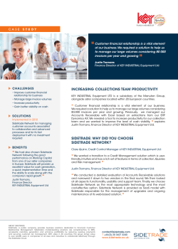
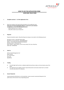
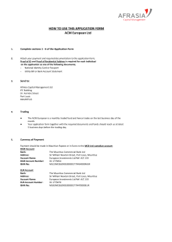
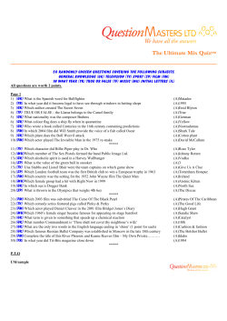
Specialist ROV Tooling Services Ltd
Unit 5 Insch Business Park, Insch,
Aberdeenshire AB52 6XF
4 Stage 10Kpsi IHPU – Operation Manual
Doc: SRTS_PRMA_905
Tel: +44 (0) 1464 821595
Email: [email protected]
Rev: 2
Page: 1 of 14
16/09/2011
2
Revised tubing layout
SW
MB
MB
27/03/2011
1
Revised document layout
SW
MB
MB
15/01/2010
0
Issued for use
SW
MB
MB
Date
Revision
Description of Revision
Prepared
Checked
Approved
All rights reserved. Disclosure to third parties of this document or any part thereof, or the use of any information contained therein for purposes
other than provided for by this document is not permitted, except with the express written permission of Specialist ROV Tooling Services Ltd.
Specialist ROV Tooling Services Ltd
Unit 5 Insch Business Park, Insch,
Aberdeenshire AB52 6XF
4 Stage 10Kpsi IHPU – Operation Manual
Doc: SRTS_PRMA_905
Tel: +44 (0) 1464 821595
Email: [email protected]
Rev: 2
Page: 2 of 14
1
Table of Contents
1 Table of Contents ........................................................................................................................................ 2 2 Introduction .................................................................................................................................................. 3 2.1 3 Scope ................................................................................................................................................... 3 Safety Recommendations ........................................................................................................................... 3 3.1 General – Operations .......................................................................................................................... 3 3.2 General – Hydraulic ............................................................................................................................. 3 3.3 General – Mechanical .......................................................................................................................... 4 4 Quality, Health, Safety and Environment (QHSE) ....................................................................................... 4 4.1 Quality .................................................................................................................................................. 4 4.2 Health and Safety ................................................................................................................................ 5 4.3 Environmental ...................................................................................................................................... 5 5 Persons to Contact ...................................................................................................................................... 5 6 Description ................................................................................................................................................... 6 7 Specifications............................................................................................................................................... 6 8 Schematic .................................................................................................................................................... 7 9 Connection to ROV ...................................................................................................................................... 8 9.1 10 Connection of Reservoir to System ..................................................................................................... 9 Operation ............................................................................................................................................... 10 10.1 Main Connections .............................................................................................................................. 11 10.2 Adjusting pressure on 3 Stage Manifold ............................................................................................ 12 10.3 Adjusting Main System Pressure ....................................................................................................... 13 11 HPW Pump Information ......................................................................................................................... 14 All rights reserved. Disclosure to third parties of this document or any part thereof, or the use of any information contained therein for purposes
other than provided for by this document is not permitted, except with the express written permission of Specialist ROV Tooling Services Ltd.
Specialist ROV Tooling Services Ltd
Unit 5 Insch Business Park, Insch,
Aberdeenshire AB52 6XF
4 Stage 10Kpsi IHPU – Operation Manual
Doc: SRTS_PRMA_905
Tel: +44 (0) 1464 821595
Email: [email protected]
Rev: 2
2
2.1
Page: 3 of 14
Introduction
Scope
The scope of this manual is to provide information regarding set up/operating instructions for the 4 Stage
10Kpsi IHPU.
3
3.1
Safety Recommendations
General – Operations
Only authorised people and qualified personnel should work on the system, and take suitable precautions to
prevent injury.
Always adhere to authorised working practices, and use the correct tools for the job. To facilitate this, make
sure that these are available before commencing.
Ensure that overalls and other garments are kept clean and free of oil or chemicals. Ensure that any cuts or
skin abrasions are protected before handling oil or chemicals to prevent ingress into the body. Protect the
hands and arms with a suitable barrier cream and gloves and ensure that all system fluids or chemicals are
removed from the skin as soon as possible.
Ensure that the working area is kept clear and uncluttered.
3.2
General – Hydraulic
Do not work on pressurised systems. Hydraulic systems contain a large amount of stored energy when
pressurised, therefore the system (including any accumulators) should be de-pressurised, and the power
pack switched off, prior to working on the system. Exceptions to this would be system adjustments to
components requiring the presence of pressure and/or flow.
Any personnel authorised to work on the system must have a complete understanding of the operation of the
hydraulic system, so that they will be aware of any system liable to remain pressurised or hazardous in any
other way.
Ensure that all personnel are clear of any mechanical/hydraulic system likely to move if pressure to system
actuators is released or applied.
Do not attempt to tighten any leaking fittings whilst under pressure. A rupture could result, leading to injury
from flying components and/or oil jets.
Regularly inspect fittings and pipe-work for mechanical damage. If any such damage is found, the item must
be repaired or replaced as necessary before pressure is applied to the system. Do not allow damaged fittings
to remain in service.
Take care when inspecting, commissioning, repairing or maintaining the system to avoid jets of oil issuing
from open orifices; pipe ends etc. if pressure is applied. Particular care should be taken to protect the eyes.
All rights reserved. Disclosure to third parties of this document or any part thereof, or the use of any information contained therein for purposes
other than provided for by this document is not permitted, except with the express written permission of Specialist ROV Tooling Services Ltd.
Specialist ROV Tooling Services Ltd
Unit 5 Insch Business Park, Insch,
Aberdeenshire AB52 6XF
4 Stage 10Kpsi IHPU – Operation Manual
Doc: SRTS_PRMA_905
Tel: +44 (0) 1464 821595
Email: [email protected]
Rev: 2
Page: 4 of 14
Hydraulic components may be heavy and slippery when covered in oil. Ensure that adequate protective
clothing and footwear is used.
Any moving component should be treated with caution when the system is pressurised during operation, and
especially during on-deck testing and repair. Keep clear of all moving components, and take all necessary
precautions to avoid injury when working on these systems by preventing movement of any components likely
to cause injury.
3.3
General – Mechanical
Ensure that all the guards are in place before applying power to the system. The power must be turned off
and any potential movement prevented before removal of any guard.
Beware of and keep clear of all moving components. Do not work on the system whilst power is applied, or if
there is any potential for components to move.
Ensure that all load bearing components are adequately and regularly inspected. If damage is found the
component must be repaired/replaced as necessary. Do not allow damaged components to remain in
service.
Some mechanical components/assemblies are heavy and, if covered in oil/water, also slippery. Always
ensure that items are correctly and adequately supported before removal, and that authorised lifting
equipment and procedures are used.
Note: trying to lift heavy components in an awkward position by hand without the
assistance of correct lifting equipment, or lifting any component without adopting the
correct stance, can lead to serious injury.
Ensure that when working within or underneath the machine that your presence is known
to your supervisor. If working underneath the machine, always ensure that there are no
loose or unsupported assemblies, components or tools above.
4
4.1
Quality, Health, Safety and Environment (QHSE)
Quality
It is the prime objective of Specialist ROV Tooling Services Ltd to perform all work safely and efficiently in
accordance with our Quality Procedure, Legislative and Client specifications and requirements. In performing
this work, the quality system of Specialist ROV Tooling Services Ltd shall be adhered to, so as to ensure that
Client requirements are met.
All rights reserved. Disclosure to third parties of this document or any part thereof, or the use of any information contained therein for purposes
other than provided for by this document is not permitted, except with the express written permission of Specialist ROV Tooling Services Ltd.
Specialist ROV Tooling Services Ltd
Unit 5 Insch Business Park, Insch,
Aberdeenshire AB52 6XF
4 Stage 10Kpsi IHPU – Operation Manual
Doc: SRTS_PRMA_905
Tel: +44 (0) 1464 821595
Email: [email protected]
Rev: 2
4.2
Page: 5 of 14
Health and Safety
The company considers that prevention of accidents incidents and hazardous occurrences resulting in injury
to personnel, damage to equipment and the environment is essential to ensure employees safety. Reducing
injuries and ill health, protecting the environment and reducing unnecessary losses and liability contributes to
a good safety record which, goes hand in hand with safe operating practices and high quality standards.
The Company is committed to continuous improvement involving the constant development of procedures,
approaches to implementation and techniques of risk assessment and control.
To meet these criteria all personnel will be trained to identify, eliminate or control the effects of hazards in
their area of work.
It is expected that all employees will exercise a personal responsibility in preventing injury to themselves, their
fellow workers, the general public and the environment.
Only through close communication and co-operation by all personnel can safety performance be established
and maintained.
It is the duty of all employees to confirm to the Company Safety Policies, codes, plans, procedures and
manuals and to accept and undertake their responsibilities.
All employees and those of our sub-contractors have a legal duty to take reasonable care of themselves and
any other person who may be affected by their acts and omissions whilst at work and to co-operate with the
Company and any persons directly or indirectly involved in the Company’s activities.
4.3
Environmental
Specialist ROV Tooling Services Ltd pledges to comply with current environment legislation and best
environmental practices, and achieve a balance between economic, social and environmental responsibilities.
We are committed to avoiding damage to the environment by any of our actions and operations.
Specialist ROV Tooling Services Ltd is committed to continual improvement, and efficient use of resources,
which will be achieved by setting and ensuring successful implementation of environmental objectives.
5
Persons to Contact
All technical enquiries relating to the tooling should be addressed to:
Mike Bisset
Specialist ROV Tooling Services Ltd
Unit 5 Insch Business Park, Insch, Aberdeenshire AB52 6TA
Telephone:
Mobile:
E-mail:
Web:
+44 (0) 1464 821595
+44 (0) 7765 248 539
[email protected]
www.specialistrov.co.uk
All rights reserved. Disclosure to third parties of this document or any part thereof, or the use of any information contained therein for purposes
other than provided for by this document is not permitted, except with the express written permission of Specialist ROV Tooling Services Ltd.
Specialist ROV Tooling Services Ltd
Unit 5 Insch Business Park, Insch,
Aberdeenshire AB52 6XF
4 Stage 10Kpsi IHPU – Operation Manual
Doc: SRTS_PRMA_905
Tel: +44 (0) 1464 821595
Email: [email protected]
Rev: 2
6
Page: 6 of 14
Description
The Specialist ROV Tooling Services Ltd 4 stage IHPU is a unit that can be utilised for many Subsea tasks
such as:
•
•
•
•
Pressure testing
Activating Blow Out Preventor
Fluid Transfer
Torque Tool Operation
The unit will pump separate media from ROV circuit held in an isolated reservoir and pump through hot stab
at pressures up to 10,000 psi. As the name suggests you can select 4 different pressures.
3 different pressures can be set to operate through Directional control valves to a maximum of 5000 psi
through the A + B PORTS and the high pressure is reached through an intensifier circuit up to 10,000 psi on
the C port. The unit can be easily reconfigured to carry out many different tasks.
The system consists of a Dynaset pump which is connected to a high pressure DCV which diverts the
pressure to a 3 stage manifold which in turn goes out to ports A and B, when the DCV is activated the
pressure then gets diverted to the Intensifier circuit which can then generate pressure up to 10,000 psi.
7
Specifications
Specification
Measurement
Hydraulic Input
Pressure
210Bar (3000psi)
Flow
35-65Lmin
Hydraulic Output
Pressure
690Bar (10000psi)
Flow
30Lmin
Directional Control
Up to 5000psi
Selectable Pressures
4 (up to 10000psi)
Fluids
Water/Glycol
Hydraulic Mineral Oil
All rights reserved. Disclosure to third parties of this document or any part thereof, or the use of any information contained therein for purposes
other than provided for by this document is not permitted, except with the express written permission of Specialist ROV Tooling Services Ltd.
Specialist ROV Tooling Services Ltd
Unit 5 Insch Business Park, Insch,
Aberdeenshire AB52 6XF
4 Stage 10Kpsi IHPU – Operation Manual
Doc: SRTS_PRMA_905
Tel: +44 (0) 1464 821595
Email: [email protected]
Rev: 2
8
Page: 7 of 14
Schematic
F
WATER/ GLYCOL
DIRECTIONAL VALVE
HYDRAULIC OIL
G
C
RETURN
2500 PSI
PRESSURE IN
4:1
INTENSIFIER
10K
ROV
SUPPLIES
P
A
P
T
MP
MP
D
TO HOT STAB
HP
3 STAGE
MANIFOLD
B
HP
5000 PSI
FOR FLUID PRESSURE
HP
E
Specialist ROV Tooling Services Ltd
Unit 1, South Road , Insch, Aberdeenshire AB 52 6 XF
Tel: +44 (0) 1224 821010 Email: info@specialistrov .co.uk
10000 PSI
4 STAGE INJECTION SYSTEM
Copyright 2008
SIZE
DATE
DWG NO
A4
23.09.09
NTS
01
SCALE
SHEET
REV
1
1 OF 1
All rights reserved. Disclosure to third parties of this document or any part thereof, or the use of any information contained therein for purposes
other than provided for by this document is not permitted, except with the express written permission of Specialist ROV Tooling Services Ltd.
Specialist ROV Tooling Services Ltd
Unit 5 Insch Business Park, Insch,
Aberdeenshire AB52 6XF
4 Stage 10Kpsi IHPU – Operation Manual
Doc: SRTS_PRMA_905
Tel: +44 (0) 1464 821595
Email: [email protected]
Rev: 2
9
Page: 8 of 14
Connection to ROV
Hydraulic connection from ROV pressure system is connected straight to Dynaset pump (marked P on panel)
however, if slower output flow is needed then simply connect through a flow control valve. The return is
connected straight from Dynaset pump back in to vehicle reservoir marked T
The hydraulic pilots are taken from vehicle GFVP as per schematic making sure there are no check valves
mounted underneath solenoids in GFVP as this will result in trapped pressure and pilot valves staying on.
The Isolated media is taken from reservoir in to rear of Dynaset pump via a 12 JIC connection.
There are 3 outputs on the unit which can easily be reconfigured to only operating two or simply one only
depending on the task you wish to perform.
Output
Pressure
Output 10K
High Pressure up to 10000psi
Output A
Through DCV pressure up to 5000psi
Output B
Through DCV pressure up to 5000psi
All rights reserved. Disclosure to third parties of this document or any part thereof, or the use of any information contained therein for purposes
other than provided for by this document is not permitted, except with the express written permission of Specialist ROV Tooling Services Ltd.
Specialist ROV Tooling Services Ltd
Unit 5 Insch Business Park, Insch,
Aberdeenshire AB52 6XF
4 Stage 10Kpsi IHPU – Operation Manual
Doc: SRTS_PRMA_905
Tel: +44 (0) 1464 821595
Email: [email protected]
Rev: 2
9.1
Page: 9 of 14
Connection of Reservoir to System
To connect a subsea reservoir to the system simply remove the cap from the suction side of pump unit and
connect to reservoir via supplied suction hose.
Remove caps and connect using
supplied suction hose (12JIC)
Subsea Reservoir
(Gel type reservoir bag)
All rights reserved. Disclosure to third parties of this document or any part thereof, or the use of any information contained therein for purposes
other than provided for by this document is not permitted, except with the express written permission of Specialist ROV Tooling Services Ltd.
Specialist ROV Tooling Services Ltd
Unit 5 Insch Business Park, Insch,
Aberdeenshire AB52 6XF
4 Stage 10Kpsi IHPU – Operation Manual
Doc: SRTS_PRMA_905
Tel: +44 (0) 1464 821595
Email: [email protected]
Rev: 2
Page: 10 of 14
10 Operation
Ensure system is connected correctly. When system is running, it will automatically provide pressure set on
the main Dynaset relief valve, this can be set up to a maximum of 5000 psi by adjusting main relief valve RV1.
If no pilot is selected the pressure will go to 3 STAGE MANIFOLD and it will automatically go down to LOW
PRESSURE setting. When Directional control valve marked either E or G is selected the LOW pressure will
then go out to either port A or B.
When a higher pressure is required then either MP (medium pressure) or HP (high pressure) pilot will need to
be activated which is done through pilots marked F for MP and D for HP .This circuit enables you to have
Directional control at 3 different pressures.
When higher pressure is needed, then the pilot marked C should be operated, which diverts pressure to the
intensifier circuit giving a maximum pressure of 10,000 psi.
Ensure plug hole is filled with aqualube
prior to diving
All rights reserved. Disclosure to third parties of this document or any part thereof, or the use of any information contained therein for purposes
other than provided for by this document is not permitted, except with the express written permission of Specialist ROV Tooling Services Ltd.
Specialist ROV Tooling Services Ltd
Unit 5 Insch Business Park, Insch,
Aberdeenshire AB52 6XF
4 Stage 10Kpsi IHPU – Operation Manual
Doc: SRTS_PRMA_905
Tel: +44 (0) 1464 821595
Email: [email protected]
Rev: 2
Page: 11 of 14
10.1 Main Connections
T
C
A
P
10Kpsi
Output
B
D
E
F
G
RV1
Drain
Suction
All rights reserved. Disclosure to third parties of this document or any part thereof, or the use of any information contained therein for purposes
other than provided for by this document is not permitted, except with the express written permission of Specialist ROV Tooling Services Ltd.
Specialist ROV Tooling Services Ltd
Unit 5 Insch Business Park, Insch,
Aberdeenshire AB52 6XF
4 Stage 10Kpsi IHPU – Operation Manual
Doc: SRTS_PRMA_905
Tel: +44 (0) 1464 821595
Email: [email protected]
Rev: 2
Page: 12 of 14
10.2 Adjusting pressure on 3 Stage Manifold
Ensure valves Marked MP and HP are screwed fully in and LP is fully out.
LP Adjustment Connect gauge to gauge port on 3 stage manifold mark GP1
Run system and monitor pressure on gauge
Adjust valve marked LP and monitor gauge readings
MP Adjustment Run System
Activate Pilot D for Med. Pressure
Adjust valve marked MP and monitor gauge readings
HP Adjustment Run System
Activate Pilot E for High pressure
Adjust HP and monitor gauge readings
Adjusting Intensifier Pressure
Ensure no air is trapped in system
Activate pilot C
Adjust relief valve mounted on intensifier
Monitor Gauge
Lock at desired pressure
Gauge Test
Point
Output Flow
Control
High Pressure
Medium Pressure
Low Pressure
All rights reserved. Disclosure to third parties of this document or any part thereof, or the use of any information contained therein for purposes
other than provided for by this document is not permitted, except with the express written permission of Specialist ROV Tooling Services Ltd.
Specialist ROV Tooling Services Ltd
Unit 5 Insch Business Park, Insch,
Aberdeenshire AB52 6XF
4 Stage 10Kpsi IHPU – Operation Manual
Doc: SRTS_PRMA_905
Tel: +44 (0) 1464 821595
Email: [email protected]
Rev: 2
Page: 13 of 14
10.3 Adjusting Main System Pressure
To adjust main system pressure of the IHPU
Take 2 x 17 mm spanners and slacken lock nut of RV1
Adjust nut nearest spring clockwise for higher pressure
Counter clockwise for lower pressure.
RV1
All rights reserved. Disclosure to third parties of this document or any part thereof, or the use of any information contained therein for purposes
other than provided for by this document is not permitted, except with the express written permission of Specialist ROV Tooling Services Ltd.
Specialist ROV Tooling Services Ltd
Unit 5 Insch Business Park, Insch,
Aberdeenshire AB52 6XF
4 Stage 10Kpsi IHPU – Operation Manual
Doc: SRTS_PRMA_905
Tel: +44 (0) 1464 821595
Email: [email protected]
Rev: 2
Page: 14 of 14
11 HPW Pump Information
All rights reserved. Disclosure to third parties of this document or any part thereof, or the use of any information contained therein for purposes
other than provided for by this document is not permitted, except with the express written permission of Specialist ROV Tooling Services Ltd.


© Copyright 2026