
AN1799 Class B Safety Software Library for 8-bit PIC16 PIC MCUs
AN1799
Class B Safety Software Library for
8-bit PIC16 PIC® MCUs
Authors:
Veena Kudva and Enrique Aleman
Microchip Technology Inc.
OVERVIEW OF THE IEC 60730
STANDARD
Note:
INTRODUCTION
This application note describes the Class B Safety
Software Library routines that detect the occurrences
of Faults in a single channel MCU. These routines
have been developed in accordance with the IEC
60730 standard to support the Class B certification process. The routines can be directly integrated with the
end user’s application to test and verify the critical
functionalities of a controller without affecting the end
user’s application.
This application note also describes the Application
Programming Interface (API) functions that are
available in the Class B Safety Software Library.
The Class B safety software routines can be called
periodically at start-up or run time to test the following
components:
•
•
•
•
•
CPU Registers
CPU Program Counter
Invariable Memory
Variable Memory
Clock
This application note also outlines various techniques,
which are not part of the Class B Safety Software
Library, to test components such as external communication, timing, I/O periphery, analog I/O and analog
multiplexer.
Note:
The term ‘IEC 60730 standard’ that is
used in this document refers to the “IEC
60730-1 ed.5.0” Copyright © 2013 IEC,
Geneva, Switzerland. www.iec.ch.
“The authors thank the International
Electrotechnical Commission (IEC) for
permission to reproduce information from
its International Standard IEC 60730-1
ed.5.0 (2013). All such extracts are copyright of IEC, Geneva, Switzerland. All
rights reserved. Further information on the
IEC is available from www.iec.ch. IEC has
no responsibility for the placement and
context in which the extracts and contents
are reproduced by the author, nor is IEC in
any way responsible for the other content
or accuracy therein.”
The IEC 60730 standard defines the test and diagnostic methods that ensure the safe operation of the controlled equipment used in household appliances.
Annex H of the IEC 60730 standard classifies the software into the following categories (see Appendix B:
“IEC 60730-1 Table H.1 (H.11.12.7 of edition 3)”):
• Class A
• Class B
• Class C
The Class B Safety Software Library implements the
important test and diagnostic methods that fall into the
Class B category. These methods use various measures to detect and respond to the software-related
Faults and errors.
According to the IEC 60730 standard, the controls with
functions that fall into the Class B category should
have one of the following structures:
• Single Channel with Functional Test
In this structure, the Functional test is executed
prior to the application firmware execution.
• Single Channel with Periodic Self-Test
In this structure, the Periodic tests are embedded
within the firmware, and the self-test occurs
periodically while the firmware is in Execution
mode.
• Dual Channel without Comparison
In this structure, two independent methods
execute the specified operations.
2014 Microchip Technology Inc.
DS00001799A-page 1
AN1799
SYSTEM REQUIREMENTS
CPU Register Test
The following system requirement is recommended to
run the Class B Safety Software Library:
The CPU Register test implements functional test
H.2.16.5, as defined by the IEC 60730 standard. It
detects stuck-at Faults in the CPU registers. This
ensures that the bits in the registers are not stuck at a
value of ‘0’ or ‘1’.
For the tests that require the independent time slot
monitoring, the system hardware must be provided
with at least two independent clock sources (e.g.,
internal oscillator, crystal oscillator and line frequency).
The CPU Register test is a non-destructive test.
This test performs the following major tasks:
CLASS B SAFETY SOFTWARE
LIBRARY
The 8-bit Class B Safety Software Library includes
APIs, which are intended to maximize application
reliability through Fault detection. These APIs help
meet the IEC 60730 standard compliance. The following tests can be implemented using this library:
•
•
•
•
•
•
CPU Register Test
Program Counter Test
Invariable Memory (Flash/EEPROM) Test
Variable Memory Test
Clock Test
Clock Test Using Line Frequency
In the following sections, the test description and the
implementation details are discussed for each test. In
addition, each section lists the APIs that are required to
execute the corresponding test.
1.
2.
The CPU registers and ghost registers are
tested by first successively writing the binary
sequences (length is dependent upon architecture), 010101... followed by 101010... into the
registers, and then reading the values from
these registers for verification.
The test returns an error code if the returned
values do not match.
API FUNCTIONS
This API function implements the CPU Register test:
CLASSB_CPURegistersTest()
Program Counter Test
The Program Counter (PC) test implements the functional test H.2.16.5 defined by the IEC 60730 standard.
The PC holds the address of the next instruction to be
executed.
The test performs the following major tasks:
1.
2.
3.
4.
The PC test invokes the functions that are
located in the Flash memory at different
addresses.
These functions reset the error flag.
The error flag is tested in many places of the
application code.
If the error flag is cleared, the PC branches to
the correct location.
API FUNCTIONS
This API function implements the PC test:
CLASSB_CPUPCTest()
DS00001799A-page 2
2014 Microchip Technology Inc.
AN1799
Invariable Memory (Flash/EEPROM) Test
1.
The Invariable Memory (Flash/EEPROM) test
implements the periodic modified checksum H.2.19.3.1
defined by the IEC 60730 standard. It detects the single-bit Faults in the invariable memory. The invariable
memory in a system, such as Flash and EEPROM
memory, contains data that is not intended to change
during the program execution. The Flash/EEPROM
Invariable Memory test computes the periodic checksum using the Cyclic Redundancy Check (CRC-16).
The CRC polynomial used to calculate the CRC-16 is
shown below.
2.
3.
4.
5.
CRC-16 = 1 1000 0000 0000 0101 = 8005 (hex)
If CRC_Flag is set to 0x00 at system start-up,
the reference CRC checksum is computed.
The reference checksum is stored in the Flash
or EEPROM memory and the CRC flag is set to
0xFF.
The CRC16 calculation function can be called
periodically if the CRC flag is set to 0xFF.
The checksum calculated from step 3 is compared
with the reference checksum.
If both values match, a status bit can be set by
the user application to indicate that the
invariable memory has passed the test and no
errors were found.
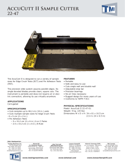
Figure 1 is the flowchart for the Invariable Memory test.
API FUNCTIONS
The CRC functions can be used to test the integrity of
data stored in either Flash or EEPROM memory.
The following API functions implement the Invariable
Memory test:
This is done by calculating and returning the CRC
value of the data stored in the location defined in the
function call.
• CLASSB_CRCFlashTest
• CLASSB_CRCEEPROMTest
• CLASSB_CRCbyte
The following flowchart illustrates how these functions
can be used in your application firmware.
FIGURE 1:
FLOWCHART FOR THE INVARIABLE MEMORY TEST*
Start
No
CRCFlag == 0
Calculate the Reference
CRC Checksum
Calculate the CRC
Yes
Yes
No
Store the Reference CRC Checksum
in the Flash/EEPROM Memory
Reference CRC == Calculated CRC
Set CRCFlag = 0xFF
Pass/No Errors Found
Fail/Errors Found
End
Note:
Other than the calls to CLASSB_CRCFlashTest and CLASSB_CRCEEPROMTest, all steps in this flowchart
are to be executed by the application firmware.
2014 Microchip Technology Inc.
DS00001799A-page 3
AN1799
Variable Memory Test
MARCH C/C- TEST
The Variable Memory test implements the Periodic
Static Memory test H.2.19.6 defined by the IEC 60730
standard. It detects single bit Faults in variable memory. The variable memory contains data, which is
intended to vary during program execution. The RAM
Memory test is used to determine if any bit of the RAM
memory is stuck at ‘1’ or ‘0’. The March Memory and
Checkerboard tests are widely used static memory
algorithms for checking the DC Faults.
The March C/C- test is used to detect the following
types of Fault in the variable memory:
The following tests can be implemented using the
Class B Safety Software Library:
• March Test
- March C/C- Test
- March B Test
MARCH TEST
A March test performs a finite set of operations on
every memory cell in a memory array. Each operation
performs the following tasks:
1.
2.
3.
4.
Writes ‘0’ to a memory cell (w0).
Writes ‘1’ to a memory cell (w1).
Reads the expected value ‘0’ from a memory
cell (r0).
Reads the expected value ‘1’ from a memory
cell (r1).
•
•
•
•
Stuck-at Fault
Addressing Fault
Transition Fault
Coupling Fault
The complexity of the March C/C- test is 11n and 10n
respectively, where n indicates the number of bits in the
memory. This test can be run as either destructive or
non-destructive. If run in non-destructive mode buffer
space is required to store the contents of the memory
to be tested and restored. If needed, this test can be
executed at the system start-up before initializing the
memory.
Example 1 shows the pseudocode that demonstrates
the implementation of the March C test.
API FUNCTIONS
This API function implements the March C/C- test:
CLASSB_RAMMarchCTest
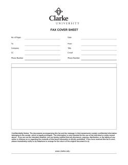
Figure 3 illustrates the March C algorithm.
FIGURE 3:
MarchC
{
March Test Notations
Figure 2 illustrates the notations that are used in the
March test.
FIGURE 2:
MARCH TEST NOTATIONS
: Arranges the address sequence in ascending
order.
: Arranges the address sequence in descending
order.
: Arranges the address sequence in either
MARCH C ALGORITHM
( w0 );
( r 0 , w 1 );
( r 1 , w0 );
( r 0 );
( r 0 , w 1 );
( r 1 , w0 );
(r 0)
}
Note: This step can be skipped for C-.
Note:
The March memory functions do not test
the Stack area of the RAM.
The following function is provided to test
the Stack:
CLASSB_RAMMarchCStackTest
ascending or descending order.
r 0 : Indicates a read operation (reads ‘0’ from a
memory cell).
r 1 : Indicates a read operation (reads ‘1’ from a
memory cell).
w 0 : Indicates a write operation (writes ‘0’ to a
memory cell).
w 1 : Indicates a write operation (writes ‘1’ to a
memory cell).
DS00001799A-page 4
2014 Microchip Technology Inc.
AN1799
EXAMPLE 1:
PSEUDOCODE FOR MARCH C TEST
/* Ascending: Write 0 */
for(i=0;i<=(n-1);i++)
x(i)=0;
/* Ascending: Read 0, Write 1 */
for(i=0;i<=(n-1);i++)
{
if (x(i)==0)
x(i) =1;
else
return fail;
}
/* Ascending: Read 1, Write 0 */
for(i=0;i<=(n-1);i++)
{
if(x(i)==1)
x(i)=0;
else
return fail;
}
/* Standard March C only
/* Ascending: Read 0*/
if ( minus != 0)
{
for(i=(n-1);i>=0;i--)
{
if(x(i)==0) {}
else
return fail ;
}
}
/* Descending: Read 0, Write 1*/
for(i=(n-1);i>=0;i--)
{
if(x(i)==0)
x(i)=1;
else
return fail;
}
/* Descending: Read 1, Write 0 */
for(i=(n-1);i>=0;i--)
{
if(x(i)==1)
x(i)=0;
else
return fail;
/* Ascending: Read 0 */
for(i=(n-1);i>=0;i--)
{
if(x(i)==0) {}
else
return fail;
}
return pass;
2014 Microchip Technology Inc.
DS00001799A-page 5
AN1799
MARCH B TEST
The March B is a non-redundant test that can detect
the following types of Fault:
• Stuck-at
• Linked Idempotent Coupling
• Inversion Coupling
This test is of complexity 17n, where n indicates the
number of bits in the memory. This test can be run as
either destructive or non-destructive. If run in nondestructive mode buffer space is required to store the
contents of the memory to be tested and restored. If
needed, this test can be executed at the system startup before initializing the memory.
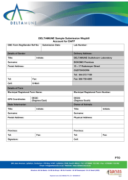
Figure 4 illustrates the March B algorithm.
FIGURE 4:
MARCH B ALGORITHM
March B
{
( w0 ); ( r 0, w1, r 1, w 0, r 0, w1); ( r 1 , w0, w1 );
( r 1, w0, w1, w 0); ( r 0 , w1, w0);
}
Example 2 shows the pseudocode that demonstrates
the implementation of the March B test.
API FUNCTIONS
This API function implements the March B test:
CLASSB_RAMMarchBTest
DS00001799A-page 6
2014 Microchip Technology Inc.
AN1799
EXAMPLE 2:
PSEUDOCODE FOR MARCH B TEST
/* Write 0 */
for(i=0;i<=(n-1);i++)
x(i)=0;
/* Ascending: Read 0, Write 1; Read 1, Write 0; Read 0, Write 1 */
for(i=0;i<=(n-1);i++)
{
if(x(i)=0)
{
x(i)==1;
}
else
return fail;
if(x(i)==1)
{
x(i)=0;
}
else
return fail;
if(x(i)==0)
{
x(i)=1;
}
else
return fail;
/* Ascending: Read 1, Write 0; Write 1 */
for(i=0;i<=(n-1);i++)
{
if(x(i)==1)
{
x(i)=0;
x(i)=1;
}
else
return fail;
/* Descending: Read 1, Write 0, Write 1, Write 0 */
for(i=(n-1);i>=0;i--)
{
if(x(i)=1)
{
x(i)=0;
x(i)=1;
x(i)=0;
}
else
return fail;
/* Descending: Read 0, Write 1, Write 0; */}
for(i=(n-1);i>=0;i--)
{
if(x(i)==0)
{
x(i)=1;
x(i)=0;
}
else
return fail;
}
return pass;
2014 Microchip Technology Inc.
DS00001799A-page 7
AN1799
CHECKERBOARD RAM TEST
Clock Test
The Checkerboard RAM test writes the checkerboard
patterns to a sequence of adjacent memory locations.
This test is performed in units (memory chunks) of 4
bytes. This is a non-destructive memory test.
According to the IEC 60730 standard, only harmonics
and subharmonics of the clock need to be tested if
using a quartz synchronized clock. The Clock test
implements frequency monitoring H.2.18.10.1 as
defined by the IEC 60730 standard. It verifies the reliability of the system clock (i.e., the system clock should
be neither too fast nor too slow).
This test performs the following major tasks:
1.
2.
3.
4.
5.
Saves the contents of the memory locations to
be tested in the buffer defined by bufferAddress.
Writes the binary value (length is dependent
upon architecture) 101010... to the memory
location, ‘N’, and the inverted binary value,
010101..., to the memory location, ‘N+1’, and
so on, until the whole memory chunk is filled.
Reads the contents of all the memory locations
in the current chunk and verifies its contents. If
the values match, the function continues;
otherwise it stops and returns an error.
Step 2 and 3 are repeated by writing the
inverted pattern to the same locations.
Once a memory chunk is completed the test of
the next chunk is started until all of the
requested memory area is tested.
API FUNCTIONS
This API function implements the Checkerboard RAM
test:
CLASSB_RAMCheckerboardTest
The Clock Test function is used to verify the proper
operation of the CPU clock.
This test performs the following major tasks:
1.
2.
3.
The independent clock source (Sosc or T1OSC)
is required for the test. The reference clock
should be connected to a timer such as Timer1.
During the test the number of CPU clock cycles
per the one reference clock period are counted.
If the number of clock cycles is outside a specified range, the function returns an error code.
API FUNCTIONS
This API function implements the Clock test:
CLASSB_ClockTest
Clock Test Using Line Frequency
The Clock Test Using Line Frequency implements the
independent-time-slot-monitoring H.2.18.10.4 defined
in the IEC60370 standard. It verifies the reliability of the
system clock (i.e., the system clock should neither be
too fast nor too slow).
This test uses the AC line frequency to verify proper
CPU clock operation. The AC line frequency is measured by using a zero-cross-detection circuit that is
connected to the input of the CCP module.
1.
2.
3.
AC line frequency is used as the independent
clock source that is required for the test.
The reference clock is measured using the CCP
module.
The API counts the ration of CPU clock counts
vs. Line Frequency counts in one second.
API FUNCTIONS
This API function implements the Clock Test Using
Line Frequency test:
CLASSB_ClockLineFreqTest
DS00001799A-page 8
2014 Microchip Technology Inc.
AN1799
Addressing of Variable and Invariable
Memory and Internal Data Path
For single chip microcontrollers or digital signal
controllers, such as PIC MCUs and dsPIC DSCs, the
Periodic Static Memory test is used to test the variable
memory, and the periodic checksum is used to test the
invariable memory. These tests detect any stuck-at
Fault in the internal address bus and internal data path.
Addressing Wrong Address
Timing
The PIC MCUs and dsPIC DSCs have several
dedicated communication interfaces, such as UART,
I2C™ and SPI modules. The IEC 60730 Class B
specifications suggest that these modules should use
time slot monitoring to ensure that the communication
occurs at the correct point in time.
Plausibility Check
This test is required only for microcontrollers with an
external memory device.
The plausibility checks on the I/O periphery, analog
multiplexer and A/D convertor can be performed as
follows:
External Communication
I/O PERIPHERY
The IEC 60730 Class B specifications suggest the following measures to ensure reliable communication
between components:
The plausibility check on an I/O pin can be performed
by toggling the I/O and checking the state of the pin.
TRANSFER REDUNDANCY
To verify the operation of the analog multiplexer, known
voltage values are applied to all channels. These values are read and compared with the applied voltage for
verification.
The transfer redundancy is a Fault/error control
technique that protects against coincidental and/or
systematic errors in the input and output information. It
is achieved by transferring the data between the transmitter and receiver. The data is transferred at least
twice in succession and then compared.
PROTOCOL TEST
The Protocol test is a Fault/error control technique in
which the data is transferred to and from the computer
components to detect errors in the internal
communication protocol.
ANALOG MULTIPLEXER
A/D CONVERTER
To test the analog functions of the A/D converter, a
known external voltage is applied to the analog inputs.
The conversion results are then compared with the
applied voltage.
CRC SINGLE WORD
A CRC polynomial is used to calculate the CRC checksum of the transmitted message. At the transmitting
end, this CRC checksum is appended to the message
before transmitting it. At the receiving end, the receiver
uses the same CRC polynomial to compute the CRC
checksum, and compares the computed value with the
received value.
2014 Microchip Technology Inc.
DS00001799A-page 9
AN1799
CLASSB_CPURegistersTest
Description
This function implements the CPU Register test. The test writes the values 0x55 and 0xAA into the CPU registers and
then reads the values from these registers for verification. The function returns CLASSB_TEST_FAIL if the values do
not match. The results are returned into the working register. Therefore the contents of the working register are not preserved. The content of the CPU register to be tested (with the exception of the interrupt shadow registers) is saved and
then restored upon the completion of the each register test. Please note that only CPU specific registers are tested.
Peripheral registers are not tested.
Prototype
CLASSBRESULT CLASSB_CPURegistersTest();
Arguments
None
Return Value
CLASSB_TEST_PASS (returned value = 0) – the test finished successfully
CLASSB_TEST_FAIL (returned value != 0) – the test is failed
Source File
CLASSB_CPURegistersTest.c
TABLE 1:
RESOURCE REQUIREMENTS
Parameter
Requirements
Program Flash Memory
96 Words
Execution Time
106 Instruction Cycles
Interrupts
Disabled
DS00001799A-page 10
2014 Microchip Technology Inc.
AN1799
CLASSB_CPUPCTest
Description
This function executes the Program Counter (PC) test, which is a functional test of the PC. The test invokes functions
that are located in the Flash memory at different addresses. The CLASSB_CPUPCTest.h header file defines the
addresses where these functions reside in the Flash memory. The functions placed at these addresses decrement the
test flag which is initialized to 2 at the beginning of the test. The flag is then verified to be 0 after CLASSB_CPUTestFunction1 and CLASSB_CPUTestFunction2 are called. Program Counter traps are implemented before each decrement to prevent errant PC jumps.
Prototype
CLASSBRESULT CLASSB_CPUPCTest();
Arguments
None
Return Value
CLASSB_TEST_PASS (returned value = 0) – the test finished successfully
CLASSB_TEST_FAIL (returned value != 0) – the test is failed
Source File
classb_pc_.s
TABLE 2:
RESOURCE REQUIREMENTS
Parameter
Requirements
Program Flash Memory
22 Words
Execution Time
34 Instruction Cycles
Interrupts
Recommended that Interrupts are Disabled
2014 Microchip Technology Inc.
DS00001799A-page 11
AN1799
CLASSB_CRCFlashTest
Description
This function implements the Invariable Memory test using the CRC-16-ANSI polynomial for CRC. It computes the CRC
of data starting at startAddress for length bytes using the crcSeed provided. This function returns the final CRC
value.
Prototype
uint16_t CLASSB_CRCFlashTest(uint16_t startAddress, uint16_t length, uint16_t crcSeed);
Arguments
• startAddress - the first address of the tested memory (must be even number)
• length - the byte length of the tested memory (must be even number)
• crcSeed - initial value of the CRC check sum
Return Value
testresult Holds the CRC result
Source File
CLASSB_CRCFlashTest.c
TABLE 3:
RESOURCE REQUIREMENTS
Parameter
Requirements
Flash Memory
63 Words
Execution Time
56322 Instruction Cycles per Kbyte
Interrupts
Enabled
DS00001799A-page 12
2014 Microchip Technology Inc.
AN1799
CLASSB_CRCEEPROMTest
Description
The function calculates the CRC check sum for the EEPROM memory region using the CRC-16-ANSI polynomial for
CRC. It computes the CRC of the EEPROM data starting at StartAddress for length bytes using the crcSeed provided.
The variables startAddress and length must be even numbers. The function returns the CRC value.
Prototype
uint16_t CLASSB_CRCEEPROMTest(uint8_t startAddress, size_t length, uint16_t crcSeed);
Arguments
• startAddress - the first address of the tested EEPROM memory in bytes (must be even number)
• length - the byte length of the tested EEPROM memory (must be even number)
• crcSeed - initial value of the CRC check sum
Return Value
crc_Result - standard 16-bit CRC check sum
Source File
CLASSB_CRCEEPROMTest.c
INCLUDE FILES
CLASSB_CRCEEPROMTest.h
CLASSB_CRCbyte.h
CLASSB_Types.h
TABLE 4:
RESOURCE REQUIREMENTS
Parameter
Requirements
Flash Memory
57 Words
Execution Time
16804 Instruction Cycles per 254 addresses (All EEPROM)
Interrupts
Enabled
2014 Microchip Technology Inc.
DS00001799A-page 13
AN1799
CLASSB_RAMMarchCTest
Description
This function implements the March C or March C minus tests for the RAM memory. This test can be run as either
destructive or non-destructive. When the buffer to store the memory content is not specified, it is run in destructive mode
and the memory content is not saved.
To run in non-destructive mode, the buffer address CLASSB_MarchbufferAddress must be defined. The tested RAM
region must not cross the storage buffer region. The interrupts are disabled during the test.
Prototype
CLASSBRESULT CLASSB_RAMMarchCTest (startAddress, length, bufferAddress, minus)
Arguments
•
•
•
•
CLASSB_MarchstartAddress - the first address of the tested RAM memory
CLASSB_MarchLength - the byte length of the tested RAM memory
CLASSB_MarchbufferAddress - the first address of the location in RAM to save user data
MARCHCMINUS - if defined, the “minus” algorithm is used
Return Value
CLASSB_TEST_PASS (returned value = 0) - the test finished successfully
CLASSB_TEST_FAIL (returned value != 0) - the test is failed
Remarks
If CLASSB_MarchbufferAddress is NULL, the test is destructive.
The Arguments to this test are all global variables to ensure that the test runs smoothly.
The test uses 7 bytes of RAM for global variables used in test.
Source File
CLASSB_RAMMarchCTest.c
TABLE 5:
RESOURCE REQUIREMENTS
Parameter
Requirements
Memory
March C 641 Words
March C- 564 Words
Execution Time
March C 99080 Instruction Cycles per 80 bytes
March C- 85912 Instruction Cycles per 80 bytes
Interrupts
Disabled during the test
DS00001799A-page 14
2014 Microchip Technology Inc.
AN1799
CLASSB_RAMMarchCStackTest
Description
This function implements the March C or March C minus tests for the Stack RAM memory.
CLASSB_MarchbufferAddress must be specified with a buffer space of 33 bytes.
Interrupts must be disabled during the test.
Prototype
CLASSBRESULT CLASSB_RAMMarchCStackTest();
Arguments
• CLASSB_MarchbufferAddress - the first address of the location in RAM to save user data
• MARCHCMINUS - if defined, the “minus” algorithm is used
Return Value
CLASSB_TEST_PASS (returned value = 0) - the test finished successfully
CLASSB_TEST_FAIL (returned value != 0) - the test is failed
Remarks
To run the stack test, 33 bytes must be allocated for the CLASSB_MarchbufferAddress.
Source File
CLASSB_RAMMarchCStackTest.c
TABLE 6:
RESOURCE REQUIREMENTS
Parameter
Requirements
Flash Memory
341 Words
Execution Time
1364 Instruction Cycles per Kbyte
Interrupts
Disabled during the test
2014 Microchip Technology Inc.
DS00001799A-page 15
AN1799
CLASSB_RAMMarchBTest
Description
This function implements the March B test for the RAM memory. This test can be run as either destructive or nondestructive. When the CLASSB_MarchbufferAddress is not specified, it is run in destructive mode and the memory
content is not saved. To run in non-destructive mode, the CLASSB_MarchbufferAddress must be defined. The
tested RAM region must not cross the storage buffer region. The interrupts are disabled during the test.
Prototype
CLASSBRESULT CLASSB_RAMMarchBTest();
Arguments
• CLASSB_MarchstartAddress - the first address of the tested RAM memory
• CLASSB_MarchLength - the byte length of the tested RAM memory
• CLASSB_MarchbufferAddress - the first address of the location in RAM to save user data
Return Value
CLASSB_TEST_PASS (returned value = 0) - the test finished successfully
CLASSB_TEST_FAIL (returned value != 0) - the test is failed
Remarks
If CLASSB_MarchbufferAddress is NULL, the test is destructive. The test uses 7 bytes of RAM for global variables
used in test.
Source File
CLASSB_RAMMarchBTest.c
TABLE 7:
RESOURCE REQUIREMENTS
Parameter
Requirements
Flash Memory
609 Words
Execution Time
97958 Instruction Cycles per 80 bytes
Interrupts
Disabled during the test
DS00001799A-page 16
2014 Microchip Technology Inc.
AN1799
CLASSB_RAMCheckerboardTest
Description
This function implements the Checkerboard test on the RAM memory. The test is performed on length (length must
be an even number) bytes starting at startAddress.
Prototype
CLASSBRESULT CLASSB_RAMCheckerboardTest (startAddress, length, bufferAddress)
Arguments
• startAddress - the first address of the tested memory (must be even number)
• length - the byte length of the tested memory (must be divisible by 4 bytes)
• bufferAddress - the first address of the RAM memory to save user data
Return Value
CLASSB_TEST_PASS (returned value = 0) - the test finished successfully
CLASSB_TEST_FAIL (returned value != 0) - the test is failed
Remarks
length must be even.
Source File
CLASSB_RAMCheckerBoardTest.c
TABLE 8:
RESOURCE REQUIREMENTS
Parameter
Requirements
Flash Memory
114 Words
Stack
1275 Instruction Cycles per 8 bytes
Interrupts
Disabled for the length of the test
2014 Microchip Technology Inc.
DS00001799A-page 17
AN1799
CLASSB_ClockTest
Description
This function implements the Clock test. It is used to verify that the CPU clock source is operating within the acceptable
frequency tolerance. The reference clock needs to be connected to Timer1. The timer must be initialized by the
application code to count the reference clock pulses.
Prototype
CLASSBRESULT CLASSB_ClockTest(uint32_t clockFrequency, uint32_t referenceFrequency, size_t
msec, uint8_t tolerance)
Arguments
•
•
•
•
clockFrequency - frequency of the clock source
referenceFrequency - frequency of the reference clock (such as power line or secondary oscillator)
msec - the time in milliseconds to run the test
tolerance - maximum valid frequency tolerance, can be from 1(0.1%) to 100(10%)
Return Value
CLASSB_TEST_PASS (returned value = 0) - the test finished successfully
CLASSB_TEST_FAIL (returned value != 0) - the test is failed
Remarks
Recommend a 20 ms test time for best results.
Will not work with a reference frequency higher than 2MHz.
Source File
CLASSB_ClockTest.c
TABLE 9:
RESOURCE REQUIREMENTS
Parameter
Requirements
Flash Memory
325 Words
Execution Time
User-defined by setting msec
Interrupts
Disabled during the test
DS00001799A-page 18
2014 Microchip Technology Inc.
AN1799
CLASSB_ClockLineFreqTest
Description
This function implements the line frequency Clock test. It is used to verify the proper operation of the CPU clock using
external zero cross detection circuitry as an input to the CCP module.
Prototype
CLASSBRESULT CLASSB_ClockTest(uint32_t clockFrequency, uint32_t referenceFrequency, size_t
msec, uint8_t tolerance)
Arguments
• clockFrequency - system clock frequency
• referenceFrequency - reference clock frequency
• tolerance - the tolerance level of the system oscillator
Return Value
None.
Remarks
This is a timing-critical test.
Changes to TMR1 during the progress of this test will cause the test to fail. This test takes one second.
This test requires the use of the CCP module and external circuitry for zero cross detection.
Source File
CLASSB_ClockLineFreqTest.c
TABLE 10:
RESOURCE REQUIREMENTS
Parameter
Requirements
Flash Memory
355 Words
Execution Cycles
1 second
Interrupts
Uses Timer1 interrupt
2014 Microchip Technology Inc.
DS00001799A-page 19
AN1799
SUMMARY
REFERENCES
This application note describes how to implement
various diagnostic measures proposed by the
IEC 60730 standard. These measures ensure the safe
operation of controlled equipment that falls under the
Class B category. In addition, this application note also
describes the different APIs that are available in the
Class B Safety Software Library. These APIs can be
directly integrated with the end user’s application to
test and verify the critical functionalities of a controller
and are intended to maximize the application reliability
through Fault detection. When implemented on a
dsPIC DSC or PIC MCU, these APIs help meet the IEC
60730 standard’s requirements.
• IEC 60730 Standard, “Automatic Electrical
Controls for Household and Similar Use”,
IEC 60730-1 ed.5, 2013
• Bushnell, M., Agarwal, V. “Essentials of Electronic
Testing for Digital, Memory, and Mixed-Signal
VLSI Circuits” New York: Springer, 1st ed. 2000.
Corr. 2nd printing, 2005
• Wu, C. “Memory Testing”
• Wu, C. “RAM Fault Models and Memory Testing”
• Suk, D.S. and Reddy, S.M. “A March Test for
Functional Faults in Semiconductor
Random-Access Memories”, lEEE Trans.
Computers, Vol. C-30, No. 12, 1981, pp. 982-985
Microchip has developed the Class B Safety Software
Library to assist you in implementing the safety
software routines. Contact your Microchip sales or
application engineer if you would like further support.
DS00001799A-page 20
2014 Microchip Technology Inc.
AN1799
APPENDIX A:
SOURCE CODE
Software License Agreement
The software supplied herewith by Microchip Technology Incorporated (the “Company”) is intended and supplied to
you, the Company’s customer, for use solely and exclusively with products manufactured by the Company.
The software is owned by the Company and/or its supplier, and is protected under applicable copyright laws. All rights
are reserved. Any use in violation of the foregoing restrictions may subject the user to criminal sanctions under applicable laws, as well as to civil liability for the breach of the terms and conditions of this license.
THIS SOFTWARE IS PROVIDED IN AN “AS IS” CONDITION. NO WARRANTIES, WHETHER EXPRESS, IMPLIED
OR STATUTORY, INCLUDING, BUT NOT LIMITED TO, IMPLIED WARRANTIES OF MERCHANTABILITY AND FITNESS FOR A PARTICULAR PURPOSE APPLY TO THIS SOFTWARE. THE COMPANY SHALL NOT, IN ANY CIRCUMSTANCES, BE LIABLE FOR SPECIAL, INCIDENTAL OR CONSEQUENTIAL DAMAGES, FOR ANY REASON
WHATSOEVER.
All of the software covered in this application note is available as a single zip file. This archive can be downloaded from
the Microchip corporate web site at:
www.microchip.com/classb
2014 Microchip Technology Inc.
DS00001799A-page 21
AN1799
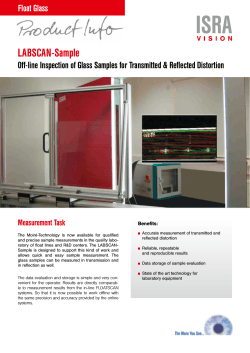
APPENDIX B:
IEC 60730-1 TABLE H.1 (H.11.12.7 OF EDITION 3)
The following table is reproduced with the permission of the International Electrotechnical Commission (IEC). IEC
60730-1 ed.5 “Copyright © 2013 IEC, Geneva, Switzerland. www.iec.ch”.
TABLE B-1:
Componentb
Table H.1 (H.11.12.7 of edition 3) – Acceptable measures to address fault/errorsa
Fault/error
Software Class
B
1. CPU
1.1
Registers
Stuck at
1.2
Instruction
decoding and
execution
1.3
Programme
counter
Stuck at
DC fault
CPU:
rq:
a
b
c
d
e
f
rq
Wrong
decoding
and execution
Definitions
Functional test, or
periodic self-test using either:
–
static memory test, or
–
word protection with single bit
redundancy
Comparison of redundant CPUs by either:
–
reciprocal comparison
–
independent hardware comparator, or
internal error detection, or
redundant memory with comparison, or
periodic self-tests using either
–
walkpat memory test
–
Abraham test
–
transparent GALPAT test; or
word protection with multi-bit redundancy,
or
static memory test and word protection
with single bit redundancy
H.2.16.5
H.2.16.6
H.2.19.6
H.2.19.8.2
C
rq
DC fault
Example of acceptable measuresc d e
rq
rq
rq
Comparison of redundant CPUs by either:
–
reciprocal comparison
–
independent hardware comparator, or
internal error detection, or
periodic self-test using equivalence class test
Functional test, or
periodic self-test, or
independent time-slot monitoring of the
program sequence, or
logical monitoring of the programme sequence
Periodic self-test and monitoring using either:
–
independent time-slot and logical
monitoring
–
internal error detection, or
comparison of redundant functional channels by
either:
–
reciprocal comparison
–
independent hardware comparator
H.2.18.15
H.2.18.3
H.2.18.9
H.2.19.5
H.2.19.7
H.2.19.1
H.2.19.2.1
H.2.19.8.1
H.2.19.6
H.2.19.8.2
H.2.18.15
H.2.18.3
H.2.18.9
H.2.18.5
H.2.16.5
H.2.16.6
H.2.18.10.4
H.2.18.10.2
H.2.16.7
H.2.18.10.3
H.2.18.9
H.2.18.15
H.2.18.3
Central programmation unit
Coverage of the fault is required for the indicated software class.
Table H.1 is applied according to the requirements of H.11.12 to H.11.12.2.12 inclusive.
For fault/error assessment, some components are divided into their subfunctions.
For each subfunction in the table, the software class C measure will cover the software class B fault/error.
It is recognized that some of the acceptable measures provide a higher level of assurance than is required
by this standard.
Where more than one measure is given for a subfunction, these are alternatives.
To be divided as necessary by the manufacturer into subfunctions.
DS00001799A-page 22
2014 Microchip Technology Inc.
AN1799
TABLE B-1:
Componentb
Table H.1 (H.11.12.7 of edition 3) – Acceptable measures to address fault/errorsa
Fault/error
Software Class
B
1.4
Addressing
1.5
Data paths
instruction
decoding
2.
Interrupt
handling and
execution
DC fault
No interrupt or
too
frequent
interrupt
No interrupt
or too
frequent
interrupt
related to
different
sources
3.
Clock
CPU:
rq:
a
b
c
d
e
f
rq
rq
rq
rq
Wrong
frequency
(for quartz
synchronized
clock:
harmonics/
subharmonics
only)
Definitions
Comparison of redundant CPUs by either:
–
reciprocal comparison
–
independent hardware comparator; or
Internal error detection; or
periodic self-test using a testing pattern of the
address lines; or
full bus redundancy, or
multi-bit bus parity
H.2.18.15
H.2.18.3
H.2.18.9
H.2.16.7
H.2.18.22
H.2.18.1.1
H.2.18.1.2
Comparison of redundant CPUs by either:
reciprocal comparison, or
independent hardware comparator, or
Internal error detection, or
periodic self-test using a testing pattern, or
data redundancy, or
multi-bit bus parity
H.2.18.15
H.2.18.3
H.2.18.9
H.2.16.7
H.2.18.2.1
H.2.18.1.2
Functional test; or
time-slot monitoring
H.2.16.5
H.2.18.10.4
C
rq
DC fault and
execution
Example of acceptable measuresc d e
rq
Comparison of redundant functional
channels by either
reciprocal comparison,
independent hardware comparator, or
Independent time-slot and logical
monitoring
H.2.18.15
H.2.18.3
H.2.18.10.3
Frequency monitoring, or
time slot monitoring
Frequency monitoring, or
time-slot monitoring, or
comparison of redundant functional channels
by either:
–
reciprocal comparison
independent hardware comparator
–
H.2.18.10.1
H.2.18.10.4
H.2.18.10.1
H.2.18.10.4
H.2.18.15
H.2.18.3
Central programmation unit
Coverage of the fault is required for the indicated software class.
Table H.1 is applied according to the requirements of H.11.12 to H.11.12.2.12 inclusive.
For fault/error assessment, some components are divided into their subfunctions.
For each subfunction in the table, the software class C measure will cover the software class B fault/error.
It is recognized that some of the acceptable measures provide a higher level of assurance than is required
by this standard.
Where more than one measure is given for a subfunction, these are alternatives.
To be divided as necessary by the manufacturer into subfunctions.
2014 Microchip Technology Inc.
DS00001799A-page 23
AN1799
TABLE B-1:
Componentb
Table H.1 (H.11.12.7 of edition 3) – Acceptable measures to address fault/errorsa
Fault/error
Software Class
B
4. Memory
4.1
Invariable
memory
All single bit
faults
rq
rq
DC fault
rq
rq
DC fault
and dynamic
cross links
4.3
Addressing
(relevant to
variable
memory and
invariable
memory)
CPU:
rq:
a
b
c
d
e
f
Stuck at
DC fault
Definitions
Periodic modified checksum; or
multiple checksum, or
word protection with single bit redundancy
Comparison of redundant CPUs by either:
–
reciprocal comparison
–
independent hardware comparator, or
H.2.19.3.1
H.2.19.3.2
H.2.19.8.2
redundant memory with comparison, or periodic
cyclic redundancy check, either
–
single word
–
double word, or
word protection with multi-bit redundancy
H.2.19.5
Periodic static memory test, or
word protection with single bit redundancy
Comparison of redundant CPUs by either:
–
reciprocal comparison
–
independent hardware comparator, or
redundant memory with comparison, or periodic
self-tests using either:
–
walkpat memory test
–
Abraham test
–
transparent G ALP AT test, or
word protection with multi-bit redundancy
H.2.19.6
H.2.19.8.2
Word protection with single bit redundancy
including the address, or
comparison of redundant CPUs by either:
–
reciprocal comparison, or
–
independent hardware comparator, or
full bus redundancy
Testing pattern, or
periodic cyclic redundancy check, either:
–
single word
–
double word, or
word protection with multi-bit redundancy
including the address
H.2.19.18.2
C
99,6 %
coverage of
all
information
errors
4.2
Variable
memory
Example of acceptable measuresc d e
rq
rq
H.2.18.15
H.2.18.3
H.2.19.4.1
H.2.19.4.2
H.2.19.8.1
H.2.18.15
H.2.18.3
H.2.19.5
H.2.19.7
H.2.19.1
H.2.19.2.1
H.2.19.8.1
H.2.18.15
H.2.18.3
H.2.18.1.1
H.2.18.22
H.2.19.4.1
H.2.19.4.2
H.2.19.8.1
Central programmation unit
Coverage of the fault is required for the indicated software class.
Table H.1 is applied according to the requirements of H.11.12 to H.11.12.2.12 inclusive.
For fault/error assessment, some components are divided into their subfunctions.
For each subfunction in the table, the software class C measure will cover the software class B fault/error.
It is recognized that some of the acceptable measures provide a higher level of assurance than is required
by this standard.
Where more than one measure is given for a subfunction, these are alternatives.
To be divided as necessary by the manufacturer into subfunctions.
DS00001799A-page 24
2014 Microchip Technology Inc.
AN1799
TABLE B-1:
Componentb
Table H.1 (H.11.12.7 of edition 3) – Acceptable measures to address fault/errorsa
Fault/error
Software Class
B
Example of acceptable measuresc d e
Definitions
Word protection with single bit redundancy
Comparison of redundant CPUs by either:
–
reciprocal comparison
–
independent hardware comparator, or
word protection with multi-bit redundancy
including the address, or data redundancy, or
testing pattern, or
protocol test
H.2.19.8.2
Word protection with single bit redundancy
including the address
Comparison of redundant CPUs by:
–
reciprocal comparison
–
independent hardware comparator, or
word protection with multi-bit redundancy,
including the address, or full bus redundancy; or
testing pattern including the address
H.2.19.8.2
Word protection with multi-bit redundancy,
or CRC – single word, or
transfer redundancy, or
protocol test
H.2.19.8.1
H.2.19.4.1
H.2.18.2.2
H.2.18.14
CRC – double word, or
H.2.19.4.2
data redundancy or comparison of redundant
functional channels by either:
–
reciprocal comparison
–
independent hardware comparator
H.2.18.2.1
Word protection with multi-bit redundancy,
including the address, or CRC – single word
including the addresses, or
transfer redundancy or
protocol test
CRC – double word, including the address, or
full bus redundancy of data and address, or
comparison of redundant communication
channels by either:
–
reciprocal comparison
–
independent hardware comparator
H.2.19.8.1
H.2.19.4.1
C
5. Internal data
path
5.1 Data
5.2 Addressing
6
External
communication
6.1
Data
Stuck at
DC fault
Wrong
address
Wrong
address and
multiple
addressing
rq
Hamming
distance 3
rq
Wrong
address
Wrong and
multiple
addressing
e
f
rq
rq
Hamming
distance 4
6.2
Addressing
CPU:
rq:
a
b
c
d
rq
rq
rq
rq
H.2.18.15
H.2.18.3
H.2.19.8.1
H.2.18.2.1
H.2.18.22
H.2.18.14
H.2.18.15
H.2.18.3
H.2.19.8.1
H.2.18.1.1
H.2.18.22
H.2.18.15
H.2.18.3
H.2.18.2.2
H.2.18.14
H.2.19.4.2
H.2.18.1.1
H.2.18.15
H.2.18.3
Central programmation unit
Coverage of the fault is required for the indicated software class.
Table H.1 is applied according to the requirements of H.11.12 to H.11.12.2.12 inclusive.
For fault/error assessment, some components are divided into their subfunctions.
For each subfunction in the table, the software class C measure will cover the software class B fault/error.
It is recognized that some of the acceptable measures provide a higher level of assurance than is required
by this standard.
Where more than one measure is given for a subfunction, these are alternatives.
To be divided as necessary by the manufacturer into subfunctions.
2014 Microchip Technology Inc.
DS00001799A-page 25
AN1799
TABLE B-1:
Componentb
Table H.1 (H.11.12.7 of edition 3) – Acceptable measures to address fault/errorsa
Fault/error
Software Class
B
6.3
Timing
Wrong point in
time
rq
rq
rq
7.
Input/output
periphery
Fault
conditions
specified in
Clause H.27
rq
rq
7.1
Digital I/O
7.2
Analog I/O
7.2.1 A/D- and
D/A- convertor
7.2.2 Analog
multiplexer
Fault
conditions
specified in
Clause H.27
rq
Wrong
addressing
rq
rq
rq
8.
Monitoring
devices and
comparators
CPU:
rq:
a
b
c
d
e
f
Any output
outside the
static and
dynamic
functional
specification
Definitions
Time-slot monitoring, or
scheduled transmission
Time-slot and logical monitoring, or
comparison of redundant communication
channels by either:
–
reciprocal comparison
–
independent hardware comparator
Logical monitoring, or
time-slot monitoring, or
scheduled transmission
(same options as for wrong point in time)
H.2.18.10.4
H.2.18.18
H.2.18.10.3
Plausibility check
H.2.18.13
Comparison of redundant CPUs by either:
–
reciprocal comparison
–
independent hardware comparator, or
H.2.18.15
H.2.18.3
input comparison, or
multiple parallel outputs; or
output verification, or
testing pattern, or
code safety
H.2.18.8
H.2.18.11
H.2.18.12
H.2.18.22
H.2.18.2
Plausibility check
H.2.18.13
Comparison of redundant CPUs by either:
–
reciprocal comparison
–
independent hardware comparator, or
input comparison, or
multiple parallel outputs, or
output verification, or
testing pattern
H.2.18.15
H.2.18.3
H.2.18.8
H.2.18.11
H.2.18.12
H.2.18.22
Plausibility check
H.2.18.13
Comparison of redundant CPUs by either:
–
reciprocal comparison
–
independent hardware comparator, or
input comparison or
testing pattern
H.2.18.15
H.2.18.3
H.2.18.8
H.2.18.22
Tested monitoring, or
redundant monitoring and comparison, or
error recognizing means
H.2.18.21
H.2.18.17
H.2.18.6
C
rq
Wrong
sequence
Example of acceptable measuresc d e
rq
H.2.18.15
H.2.18.3
H.2.18.10.2
H.2.18.10.4
H.2.18.18
Central programmation unit
Coverage of the fault is required for the indicated software class.
Table H.1 is applied according to the requirements of H.11.12 to H.11.12.2.12 inclusive.
For fault/error assessment, some components are divided into their subfunctions.
For each subfunction in the table, the software class C measure will cover the software class B fault/error.
It is recognized that some of the acceptable measures provide a higher level of assurance than is required
by this standard.
Where more than one measure is given for a subfunction, these are alternatives.
To be divided as necessary by the manufacturer into subfunctions.
DS00001799A-page 26
2014 Microchip Technology Inc.
AN1799
TABLE B-1:
Componentb
Table H.1 (H.11.12.7 of edition 3) – Acceptable measures to address fault/errorsa
Fault/error
Software Class
B
9.
Custom
chips f
for example,
ASIC,
GAL, Gate
array
CPU:
rq:
a
b
c
d
e
f
Any output
outside the
static and
dynamic
functional
specification
Example of acceptable measuresc d e
Definitions
Periodic self-test
H.2.16.6
Periodic self-test and monitoring, or
H.2.16.7
dual channel (diverse) with comparison, or
error recognizing means
H.2.16.2
H.2.18.6
C
rq
rq
Central programmation unit
Coverage of the fault is required for the indicated software class.
Table H.1 is applied according to the requirements of H.11.12 to H.11.12.2.12 inclusive.
For fault/error assessment, some components are divided into their subfunctions.
For each subfunction in the table, the software class C measure will cover the software class B fault/error.
It is recognized that some of the acceptable measures provide a higher level of assurance than is required
by this standard.
Where more than one measure is given for a subfunction, these are alternatives.
To be divided as necessary by the manufacturer into subfunctions.
2014 Microchip Technology Inc.
DS00001799A-page 27
AN1799
NOTES:
DS00001799A-page 28
2014 Microchip Technology Inc.
AN1799
APPENDIX C:
REVISION HISTORY
Revision A (October 2014)
This is the initial release of this application note.
2014 Microchip Technology Inc.
DS00001799A-page 29
AN1799
NOTES:
DS00001799A-page 30
2014 Microchip Technology Inc.
Note the following details of the code protection feature on Microchip devices:
•
Microchip products meet the specification contained in their particular Microchip Data Sheet.
•
Microchip believes that its family of products is one of the most secure families of its kind on the market today, when used in the
intended manner and under normal conditions.
•
There are dishonest and possibly illegal methods used to breach the code protection feature. All of these methods, to our
knowledge, require using the Microchip products in a manner outside the operating specifications contained in Microchip’s Data
Sheets. Most likely, the person doing so is engaged in theft of intellectual property.
•
Microchip is willing to work with the customer who is concerned about the integrity of their code.
•
Neither Microchip nor any other semiconductor manufacturer can guarantee the security of their code. Code protection does not
mean that we are guaranteeing the product as “unbreakable.”
Code protection is constantly evolving. We at Microchip are committed to continuously improving the code protection features of our
products. Attempts to break Microchip’s code protection feature may be a violation of the Digital Millennium Copyright Act. If such acts
allow unauthorized access to your software or other copyrighted work, you may have a right to sue for relief under that Act.
Information contained in this publication regarding device
applications and the like is provided only for your convenience
and may be superseded by updates. It is your responsibility to
ensure that your application meets with your specifications.
MICROCHIP MAKES NO REPRESENTATIONS OR
WARRANTIES OF ANY KIND WHETHER EXPRESS OR
IMPLIED, WRITTEN OR ORAL, STATUTORY OR
OTHERWISE, RELATED TO THE INFORMATION,
INCLUDING BUT NOT LIMITED TO ITS CONDITION,
QUALITY, PERFORMANCE, MERCHANTABILITY OR
FITNESS FOR PURPOSE. Microchip disclaims all liability
arising from this information and its use. Use of Microchip
devices in life support and/or safety applications is entirely at
the buyer’s risk, and the buyer agrees to defend, indemnify and
hold harmless Microchip from any and all damages, claims,
suits, or expenses resulting from such use. No licenses are
conveyed, implicitly or otherwise, under any Microchip
intellectual property rights.
Trademarks
The Microchip name and logo, the Microchip logo, dsPIC,
FlashFlex, flexPWR, JukeBlox, KEELOQ, KEELOQ logo, Kleer,
LANCheck, MediaLB, MOST, MOST logo, MPLAB,
OptoLyzer, PIC, PICSTART, PIC32 logo, RightTouch, SpyNIC,
SST, SST Logo, SuperFlash and UNI/O are registered
trademarks of Microchip Technology Incorporated in the
U.S.A. and other countries.
The Embedded Control Solutions Company and mTouch are
registered trademarks of Microchip Technology Incorporated
in the U.S.A.
Analog-for-the-Digital Age, BodyCom, chipKIT, chipKIT logo,
CodeGuard, dsPICDEM, dsPICDEM.net, ECAN, In-Circuit
Serial Programming, ICSP, Inter-Chip Connectivity, KleerNet,
KleerNet logo, MiWi, MPASM, MPF, MPLAB Certified logo,
MPLIB, MPLINK, MultiTRAK, NetDetach, Omniscient Code
Generation, PICDEM, PICDEM.net, PICkit, PICtail,
RightTouch logo, REAL ICE, SQI, Serial Quad I/O, Total
Endurance, TSHARC, USBCheck, VariSense, ViewSpan,
WiperLock, Wireless DNA, and ZENA are trademarks of
Microchip Technology Incorporated in the U.S.A. and other
countries.
SQTP is a service mark of Microchip Technology Incorporated
in the U.S.A.
Silicon Storage Technology is a registered trademark of
Microchip Technology Inc. in other countries.
GestIC is a registered trademarks of Microchip Technology
Germany II GmbH & Co. KG, a subsidiary of Microchip
Technology Inc., in other countries.
All other trademarks mentioned herein are property of their
respective companies.
© 2014, Microchip Technology Incorporated, Printed in the
U.S.A., All Rights Reserved.
ISBN: 978-1-63276-640-3
QUALITY MANAGEMENT SYSTEM
CERTIFIED BY DNV
== ISO/TS 16949 ==
2014 Microchip Technology Inc.
Microchip received ISO/TS-16949:2009 certification for its worldwide
headquarters, design and wafer fabrication facilities in Chandler and
Tempe, Arizona; Gresham, Oregon and design centers in California
and India. The Company’s quality system processes and procedures
are for its PIC® MCUs and dsPIC® DSCs, KEELOQ® code hopping
devices, Serial EEPROMs, microperipherals, nonvolatile memory and
analog products. In addition, Microchip’s quality system for the design
and manufacture of development systems is ISO 9001:2000 certified.
DS00001799A-page 31
Worldwide Sales and Service
AMERICAS
ASIA/PACIFIC
ASIA/PACIFIC
EUROPE
Corporate Office
2355 West Chandler Blvd.
Chandler, AZ 85224-6199
Tel: 480-792-7200
Fax: 480-792-7277
Technical Support:
http://www.microchip.com/
support
Web Address:
www.microchip.com
Asia Pacific Office
Suites 3707-14, 37th Floor
Tower 6, The Gateway
Harbour City, Kowloon
Hong Kong
Tel: 852-2943-5100
Fax: 852-2401-3431
India - Bangalore
Tel: 91-80-3090-4444
Fax: 91-80-3090-4123
Austria - Wels
Tel: 43-7242-2244-39
Fax: 43-7242-2244-393
Denmark - Copenhagen
Tel: 45-4450-2828
Fax: 45-4485-2829
Atlanta
Duluth, GA
Tel: 678-957-9614
Fax: 678-957-1455
Austin, TX
Tel: 512-257-3370
Boston
Westborough, MA
Tel: 774-760-0087
Fax: 774-760-0088
Chicago
Itasca, IL
Tel: 630-285-0071
Fax: 630-285-0075
Cleveland
Independence, OH
Tel: 216-447-0464
Fax: 216-447-0643
Dallas
Addison, TX
Tel: 972-818-7423
Fax: 972-818-2924
Detroit
Novi, MI
Tel: 248-848-4000
Houston, TX
Tel: 281-894-5983
Indianapolis
Noblesville, IN
Tel: 317-773-8323
Fax: 317-773-5453
Los Angeles
Mission Viejo, CA
Tel: 949-462-9523
Fax: 949-462-9608
New York, NY
Tel: 631-435-6000
San Jose, CA
Tel: 408-735-9110
Canada - Toronto
Tel: 905-673-0699
Fax: 905-673-6509
DS00001799A-page 32
Australia - Sydney
Tel: 61-2-9868-6733
Fax: 61-2-9868-6755
China - Beijing
Tel: 86-10-8569-7000
Fax: 86-10-8528-2104
China - Chengdu
Tel: 86-28-8665-5511
Fax: 86-28-8665-7889
China - Chongqing
Tel: 86-23-8980-9588
Fax: 86-23-8980-9500
China - Hangzhou
Tel: 86-571-8792-8115
Fax: 86-571-8792-8116
China - Hong Kong SAR
Tel: 852-2943-5100
Fax: 852-2401-3431
China - Nanjing
Tel: 86-25-8473-2460
Fax: 86-25-8473-2470
China - Qingdao
Tel: 86-532-8502-7355
Fax: 86-532-8502-7205
China - Shanghai
Tel: 86-21-5407-5533
Fax: 86-21-5407-5066
China - Shenyang
Tel: 86-24-2334-2829
Fax: 86-24-2334-2393
China - Shenzhen
Tel: 86-755-8864-2200
Fax: 86-755-8203-1760
China - Wuhan
Tel: 86-27-5980-5300
Fax: 86-27-5980-5118
China - Xian
Tel: 86-29-8833-7252
Fax: 86-29-8833-7256
India - New Delhi
Tel: 91-11-4160-8631
Fax: 91-11-4160-8632
India - Pune
Tel: 91-20-3019-1500
Japan - Osaka
Tel: 81-6-6152-7160
Fax: 81-6-6152-9310
Japan - Tokyo
Tel: 81-3-6880- 3770
Fax: 81-3-6880-3771
Korea - Daegu
Tel: 82-53-744-4301
Fax: 82-53-744-4302
Korea - Seoul
Tel: 82-2-554-7200
Fax: 82-2-558-5932 or
82-2-558-5934
France - Paris
Tel: 33-1-69-53-63-20
Fax: 33-1-69-30-90-79
Germany - Dusseldorf
Tel: 49-2129-3766400
Germany - Munich
Tel: 49-89-627-144-0
Fax: 49-89-627-144-44
Germany - Pforzheim
Tel: 49-7231-424750
Italy - Milan
Tel: 39-0331-742611
Fax: 39-0331-466781
Italy - Venice
Tel: 39-049-7625286
Malaysia - Kuala Lumpur
Tel: 60-3-6201-9857
Fax: 60-3-6201-9859
Netherlands - Drunen
Tel: 31-416-690399
Fax: 31-416-690340
Malaysia - Penang
Tel: 60-4-227-8870
Fax: 60-4-227-4068
Poland - Warsaw
Tel: 48-22-3325737
Philippines - Manila
Tel: 63-2-634-9065
Fax: 63-2-634-9069
Singapore
Tel: 65-6334-8870
Fax: 65-6334-8850
Taiwan - Hsin Chu
Tel: 886-3-5778-366
Fax: 886-3-5770-955
Spain - Madrid
Tel: 34-91-708-08-90
Fax: 34-91-708-08-91
Sweden - Stockholm
Tel: 46-8-5090-4654
UK - Wokingham
Tel: 44-118-921-5800
Fax: 44-118-921-5820
Taiwan - Kaohsiung
Tel: 886-7-213-7830
Taiwan - Taipei
Tel: 886-2-2508-8600
Fax: 886-2-2508-0102
Thailand - Bangkok
Tel: 66-2-694-1351
Fax: 66-2-694-1350
China - Xiamen
Tel: 86-592-2388138
Fax: 86-592-2388130
China - Zhuhai
Tel: 86-756-3210040
Fax: 86-756-3210049
03/25/14
2014 Microchip Technology Inc.


© Copyright 2026