
PRODUCT SUBMITTAL / SUBSTITUTION REQUEST
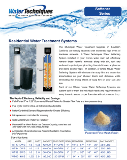
PRODUCT SUBMITTAL / SUBSTITUTION REQUEST
TO:
PROJECT:
SPECIFIED ITEM:
Section
Page
Paragraph
Description
P R O D U C T S U B M I T TA L / S U B S T I T U T I O N R E Q U E S T E D :
PE1000+ Adhesive Anchoring System for Cracked and Uncracked Concrete.
Code Listed as given in ICC-ES ESR-2583 (www.Powers.com)
The attached submittal package includes the product description, specifications, drawings, and performance data for use in the evaluation
of the request.
S U B M I T T E D B Y:
Name:
Signature:
Company:
Address:
Date:
Telephone:
Fax:
FOR USE BY THE ARCHITECT AND/OR ENGINEER
■ Approved
■ Approved as Noted
■ Not Approved
(If not approved, please briefly explain why the product was not accepted.)
By:
Remarks:
Date:
PE1000+
TM
PRODUCT INFORMATION
PE1000+
TM
Epoxy Injection Adhesive Anchoring System
SECTION CONTENTS
PRODUCT DESCRIPTION
The PE1000+ is a two-component, high strength adhesive anchoring system. The system
includes injection adhesive in plastic cartridges, mixing nozzles, dispensing tools and hole
cleaning equipment. The PE1000+ is designed for bonding threaded rod and reinforcing bar
hardware into drilled holes in concrete base and solid masonry materials.
Page No.
General Information .......................1
Installation Specifications .............2
Installation Instructions .................3
Performance Data ...........................6
Ordering Information .................. 17
GENERAL APPLICATIONS AND USES
• Bonding threaded rod and reinforcing bar into hardened concrete and grouted CMU
• Evaluated for installation and use in dry and water-saturated concrete including water-filled holes
• Suitable to resist loads in cracked or uncracked concrete base materials for cases where anchor
design theory and criteria applies
• Qualified for seismic and wind loading (see ESR-2583)
• Can be installed in a wide range of base material temperatures
PE1000+ dual cartridge
and mixing nozzle
FEATURES AND BENEFITS
+ Designed for use with threaded rod and reinforcing bar hardware elements
+ Consistent performance in low and high strength concrete (2,500 to 8,500 psi)
+ Evaluated and recognized for freeze/thaw performance
+ Evaluated and recognized for long term and short term loading
(see performance tables for applicable temperature ranges)
+ Evaluated and recognized for variable embedments (see installation specifications)
+ Cartridge design allows for multiple uses using extra mixing nozzles
+ Mixing nozzles proportion adhesive and provide simple delivery method into drilled holes
+ Easy dispensing reduces applicator fatique
APPROVALS AND LISTINGS
International Code Council, Evaluation Service (ICC-ES) ESR-2583
Code compliant with the 2006 IBC, 2006 IRC, 2003 IBC, 2003 IRC, 2000 IBC, 2000 IRC and 1997 UBC
Tested in accordance with AC308 for use in structural concrete according to ACI 318 Appendix D
(Strength Design) and as amended by provisions of ICC-ES AC308 Annex A, Section 3.3 (www.icc-es.org)
Evaluated and qualified by an accredited independent testing laboratory for recognition in cracked and
uncracked concrete including seismic and wind loading
Compliant with NSF/ANSI Standard 61 for drinking water system components – health effects;
minimum requirements for materials in contact with potable water and water treatment
Conforms to requirements of ASTM C 881, Types I, II, IV and V, Grade 3, Classes B & C
(also meets type III except for elongation)
Department of Transportation listings – see www.powers.com or contact transportation agency
PACKAGING
Dual (side-by-side) Cartridge
13 fl. oz. (385 ml)
20 fl. oz. (585ml)
STORAGE LIFE & CONDITIONS
Two years in a dry, dark environment with
temperature ranging from 41oF and 95oF
(5oC to 35oC)
ANCHOR SIZE RANGE (TYP.)
3/8" to 1-1/4" diameter threaded rod
No. 3 to No.10 reinforcing bar (rebar)
SUITABLE BASE MATERIALS
Normal-weight concrete
Grouted concrete masonry
GUIDE SPECIFICATIONS
CSI Divisions: 03151-Concrete Anchoring, 04081-Masonry Anchorage and 05090-Metal Fastenings.
Adhesive anchoring system shall be PE1000+ as supplied by Powers Fasteners, Inc., Brewster, NY.
Anchors shall be installed in accordance with published instructions and requirements of the
Authority Having Jurisdiction.
This Product Available In
Powers Design Assist
Real Time Anchor Design Software
www.powersdesignassist.com
d1
1
www.powers.com
Canada: (905) 673-7295 or (514) 631-4216
Powers USA: (800) 524-3244 or (914) 235-6300
PE1000+
TM
PRODUCT INFORMATION
INSTALLATION SPECIFICATIONS
Installation Specifications for Threaded Rod and Reinforcing Bar
Notation
Units
Threaded rod
-
-
3/8’’
1/2”
5/8”
3/4’’
7/8”
1”
-
1-1/4”
-
Reinforcing bar
-
-
#3
#4
#5
#6
#7
#8
#9
-
#10
Nominal anchor diameter
d
in.
(mm)
0.375
(9.5)
0.500
(12.7)
0.625
(15.9)
0.750
(19.1)
0.875
(22.2)
1.000
(25.4)
1.125
(28.6)
1.250
(31.8)
1.250
(31.8)
Nominal diameter of drilled hole
do,(dbit)
in.
7/16
ANSI
9/16
ANSI
11/16
ANSI
7/8
ANSI
1
ANSI
1-1/8
ANSI
1-3/8
ANSI
1-3/8
ANSI
1-1/2
ANSI
Minimum embedment1
hef,min
in.
(mm)
2-3/8
(61)
2-3/4
(70)
3-1/8
(79)
3-1/2
(89)
3-1/2
(89)
4
(102)
4-1/2
(114)
5
(127)
5
(127)
Maximum embedment1
hef,max
in.
(mm)
4-1/2
(114)
6
(153)
7-1/2
(191)
9
(229)
10-1/2
(267)
12
(305)
13-1/2
(343)
15
(381)
15
(381)
Minimum concrete member thickness1
hmin
in.
(mm)
Minimum spacing distance1
smin
in.
(mm)
1-7/8
(48)
2-1/2
(62)
3-1/8
(80)
3-1/2
(95)
4-3/8
(111)
5
(127)
5-5/8
(143)
6-1/4
(159)
6-1/4
(159)
Minimum edge distance1
cmin
in.
(mm)
1-7/8
(48)
2-1/2
(64)
3-1/8
(80)
3-1/2
(95)
4-3/8
(111)
5
(127)
5-5/8
(143)
6-1/4
(159)
6-1/4
(159)
A307 Grade C or F 1554
carbon steel rod
Tmax
ft.-lb.
(N-m)
10
(13)
25
(34)
50
(68)
90
(122)
125
(169)
165
(224)
-
280
(379)
-
F593 Condition CW stainless
steel rod or ASTM A193,
Grade B7 carbon steel rod
Tmax
ft.-lb.
(N-m)
16
(22)
33
(45)
60
(81)
105
(142)
125
(169)
165
(224)
-
280
(379)
-
Effective cross sectional area of threaded rod
Ase
in.2
(mm2)
0.078
(50)
0.142
(92)
0.226
(146)
0.335
(216)
0.462
(298)
0.606
(391)
-
0.969
(625)
-
Effective cross sectional area of reinforcing bar
Ase
in.2
(mm2)
0.110
(71)
0.200
(129)
0.310
(200)
0.440
(284)
0.600
(387)
0.790
(510)
1.000
(645)
-
1.270
(819)
Dimension/Property
Maximum torque
(only possible
after full cure
time of adhesive)
Nominal Anchor Size
hef + 1-1/4
(hef + 30)
hef + 2do
1. For use with the design provisions of ACI 318 Appendix D and ICC-ES AC308 Appendix A, Section 3.3 and ESR-2583.
Detail of Steel
Hardware Elements used with
Injection Adhesive System
Threaded Rod
or Rebar
Threaded Rod and Deformed Reinforcing Bar Material Properties
Steel
Description
(General)
Steel
Specification
(ASTM)
Nomial Anchor
Size
(inch)
Minimum
Yield Strength,
fy (ksi)
Minimum
Ultimate
Strength,
fu (ksi)
Carbon rod1
A 307,
Grade C or F 1554
3/8 through 1-1/4
36.0
58.0
Stainless rod
(Alloy 304 / 316)
F 593,
Condition CW
3/8 through 5/8
65.0
100.0
3/4 through 1-1/4
45.0
85.0
High strength
carbon rod
A 193,
Grade B7
3/8 through 1-1/4
105.0
120.0
Grade 60
reinforcing bar
A 615, A 706,
A 767, or A 996
3/8 through 1-1/4
(#3 through #10)
60.0
90.0
1. ASTM A 36 carbon steel threaded rod is equivalent in listed properties.
d1
Powers USA: (800) 524-3244 or (914) 235-6300
Canada: (905) 673-7295 or (514) 631-4216
www.powers.com
2
PE1000+
TM
PRODUCT INFORMATION
INSTALLATION INSTRUCTIONS (SOLID BASE MATERIALS)
DRILLING
1 - Drill a hole into the base material with a rotary hammer drill tool to the size and embedment required
by the selected anchor (reference installation specifications for threaded rod and reinforcing bar). The
tolerances of the carbide drill bit should meet the requirements of ANSI Standard B212.15.
Precaution: Wear suitable eye and skin protection. Avoid inhalation of dusts during drilling and/or removal.
Note! After drilling and prior to hole cleaning, all standing water in the drilled bore hole must be
removed if present (e.g. vacuum, compressed air, etc.)
HOLE CLEANING
¦ BLOW 4x, BRUSH 4x, BLOW 4x
2a - Starting from the bottom or back of the anchor hole, blow the hole clean using a compressed air
nozzle (min. 90 psi) or a hand pump (supplied by Powers Fasteners) a minimum of four times (4x).
• Use a compressed air nozzle (min. 90 psi) or a hand pump (min. volume 25 fl. oz.) for anchor rod
3/8" to 3/4" diameter or reinforcing bar (rebar) sizes #3 to #6.
• Use a compressed air nozzle (min. 90 psi) for anchor rod 7/8" to 1-1/4" diameter and rebar sizes
#7 to #10. A hand pump shall not be used with these anchor sizes.
2b - Determine wire brush diameter (reference hole cleaning equipment selection table) and attach
the brush with adaptor to a rotary drill tool or battery screwgun. Brush the hole with the selected
wire brush a minimum of four times (4x). A brush extension (supplied by Powers Fasteners, Cat.
#08282) should be used for holes drilled deeper than the listed brush length.
The wire brush diameter should be checked periodically during use. The brush must be replaced if it
becomes worn (less than Dmin, reference hole cleaning equipment selection table) or does not come
into contact with the sides of the drilled hole.
2c - Finally, blow the hole clean again a minimum of four times (4x).
• Use a compressed air nozzle (min. 90 psi) or a hand pump (min. volume 25 fl. oz.) for anchor rod
3/8" to 3/4" diameter or reinforcing bar (rebar) sizes #3 to #6.
• Use a compressed air nozzle (min. 90 psi) for anchor rod 7/8" to 1-1/4" diameter and rebar sizes
#7 to #10. A hand pump shall not be used with these anchor sizes.
When finished the hole should be clean and free of dust, debris, ice, grease, oil or other foreign
material.
(Continued on next page)
d1
3
www.powers.com
Canada: (905) 673-7295 or (514) 631-4216
Powers USA: (800) 524-3244 or (914) 235-6300
PRODUCT INFORMATION
PE1000+
TM
INSTALLATION INSTRUCTIONS (SOLID BASE MATERIALS)
PREPARING
3- Check adhesive expiration date on cartridge label. Do not use expired product. Review Material Safety
Data Sheet (MSDS) before use. Cartridge temperature must be between 41°F - 104°F (5°C - 40°C) when
in use. Consideration should be given to the reduced gel time of the adhesive in warm temperatures.
Attach a supplied mixing nozzle to the cartridge. Do not modify the mixer in any way and make sure the
mixing element is inside the nozzle. Load the cartridge into the correct dispensing tool.
A new mixing nozzle must be used for every working interruption longer than the published working
times (reference gel time and curing time table) as well as for new cartridges.
4- Prior to inserting the anchor rod or rebar into the filled bore hole, the position of the
embedment depth has to be marked on the anchor. Verify anchor element is straight and free of
surface damage.
5- For new cartridges and nozzles: prior to dispensing into the anchor hole, squeeze out separately a
minimum three full strokes of the mixed adhesive. Discard non-uniform adhesive until the mixed adhesive
shows a consistent red color.
Review and note the published working and cure times (reference gel time and curing time table) prior
to injection of the mixed adhesive into the cleaned anchor hole.
INSTALLATION
6- Fill the cleaned hole approximately two-thirds full with mixed adhesive starting from the bottom
or back of the anchor hole. Slowly withdraw the mixing nozzle as the hole fills to avoid creating air
pockets or voids. For embedment depth greater than 7-1/2” an extension nozzle (3/8” dia.) must be
used with the mixing nozzle.
With Piston Plug
Piston plugs (see Adhesive Piston Plug Table) must be used with and attached to mixing nozzle and
extension tube for horizontal and overhead installations with anchor rod from 3/4" to 1-1/4"
diameter and rebar sizes #6 to #10. Insert piston plug to the back of the drilled hole and inject as
described in the method above. During installation the piston plug will be naturally extruded from
the drilled hole by the adhesive pressure.
Attention! Do not install anchors overhead without proper training and installation hardware
provided by Powers Fasteners. Contact Powers for details prior to use.
7- The anchor should be free of dirt, grease, oil or other foreign material. Push clean threaded rod
or reinforcing bar into the anchor hole while turning slightly to ensure positive distribution of the
adhesive until the embedment depth is reached. Air pockets are present when the threaded rod or
rebar springs or air pockets burst during installation. In case of air pockets: remove rod or rebar, let
the adhesive harden, re-drill the hole and repeat the complete installation.
8- Be sure that the anchor is fully seated at the bottom of the hole and that some adhesive has flowed
from the hole and all around the top of the anchor. If there is not enough adhesive in the hole, the
installation must be repeated. For overhead applications the anchor must be secured from moving/falling
during the cure time (e.g. wedges). Minor adjustments to the anchor may be performed during the gel
time but the anchor shall not be moved after final placement and during cure.
(Continued on next page)
d1
Powers USA: (800) 524-3244 or (914) 235-6300
Canada: (905) 673-7295 or (514) 631-4216
www.powers.com
4
PE1000+
TM
PRODUCT INFORMATION
INSTALLATION INSTRUCTIONS (SOLID BASE MATERILAS)
CURING AND FIXTURE
9- Allow the adhesive anchor to cure to the specified full curing time prior to applying any load
(reference gel time and curing time table).
Do not disturb, torque or load the anchor until it is fully cured.
10- After full curing of the adhesive anchor, a fixture can be installed to the anchor and tightened up to
the maximum torque (reference gel time and curing time table) by using a calibrated torque wrench.
Take care not to exceed the maximum torque for the selected anchor.
REFERENCE TABLES FOR INSTALLATION
Gel (working) Time and Curing Table
Temperature of base material
Gel (working) time
Full curing time
5
180 minutes
50 hours
50
10
120 minutes
24 hours
68
20
30 minutes
10 hours
86
30
20 minutes
6 hours
104
40
20 minutes
4 hours
o
F
41
o
C
Hole Cleaning Equipment Selection Table for PE1000+
Threaded rod
diameter
(inch)
Rebar size
(no.)
ANSI drill bit
diameter
(inch)
Min. brush
diameter, Dmin
(inches)
Brush length, L
(inches)
Steel wire
brush
(Cat. #)
Blowout
tool
3/8
#3
7/16
0.475
6-3/4
08284
1/2
#4
9/16
0.600
6-3/4
08285
5/8
#5
11/16
0.735
7-7/8
08286
3/4
#6
7/8
0.920
7-7/8
08287
Hand-pump
cat# 08280
or
compressed air
nozzle
(min. 90 psi)
7/8
#7
1
1.045
11-7/8
08288
1
#8
1-1/8
1.175
11-7/8
08289
1-1/4
#9
1-3/8
1.425
11-7/8
08290
-
#10
1-1/2
1.550
11-7/8
08291
Compressed air
nozzle only
(min. 90 psi)
Number of
cleaning actions
4x blowing
4x brushing
4x blowing
An SDS-plus adaptor (Cat. #08283) or Jacobs chuck style adaptor (Cat. #08296) is required to attach a steel wire brush to the drill tool.
Adhesive Piston Plugs
Threaded rod
diameter
(inch)
Rebar
size
(no.)
ANSI drill bit
diameter
(inch)
Plug
Size
(inch)
Plastic
Plug
(Cat. #)
3/4
#6
7/8
7/8
08300
7/8
#7
1
1
08301
1
#8
1-1/8
1-1/8
08303
1-1/4
#9
1-3/8
1-3/8
08305
-
#10
1-1/2
1-1/2
08309
A plastic extension tube (3/8” dia., Cat# 08281) must be used with piston plugs.
5
www.powers.com
Canada: (905) 673-7295 or (514) 631-4216
Horizontal and
overhead installations
d1
Powers USA: (800) 524-3244 or (914) 235-6300
PE1000+
TM
PRODUCT INFORMATION
PERFORMANCE DATA
Tension Design Information for Threaded Rod and Reinforcing Bar in Normal-Weight Concrete
(For use with load combinations taken from ACI 318 Section 9.2)1,2
Design Characteristic
Notation Units
3/8”
#3
1/2”
#4
Nominal Anchor Size
5/8”
1”
7/8”
3/4”
#6
#5
#8
#7
2-3/8
2-3/4
3-1/8
3-1/2
3-1/2
4
in.
(mm)
(70)
(70)
(79)
(89)
(89)
(102)
3
STEEL STRENGTH IN TENSION
0.078
0.142
0.226
0.335
0.462
0.606
in.2
Ase
Effective cross sectional area of threaded rod
(50)
(92)
(146)
(216)
(289)
(391)
(mm2)
4,525
8,235
13,110 19,430 26,795 35,150
Carbon rod
lb
Nsa
(20.1)
(36.6)
(58.3)
(86.4)
(119.2) (156.3)
(kN)
(ASTM A 307, Grade C or F 1554)
7,800
14,200 22,600 28,475 39,270 51,510
Stainless steel rod - alloy 304/316
lb
Steel
Nsa
(34.7)
(63.2)
(100.5) (126.7) (174.7) (229.1)
(kN)
strength in (ASTM F 593, Condition CW)
9,360
17,040 27,120 40,200 55,440 72,720
High strength carbon rod
lb
tension
Nsa
(41.6)
(75.8)
(120.6) (178.8) (246.6) (323.5)
(kN)
(ASTM A 193, Grade B7)
2
0.110
0.200
0.310
0.440
0.600
0.790
in
.
Ase
Effective cross sectional area of reinforcing bar
(71)
(129)
(200)
(284)
(387)
(510)
(mm2)
9,900
18,000 27,900 39,600 54,000 71,100
Steel strength in tension,
lb
Nsa
(44.0)
(80.1)
(124.1) (176.1) (240.2) (316.3)
(kN)
Grade 60 reinforcing bars
Ø
0.75 (0.65 for ASTM F 593 Stainless)
Reduction factor for steel strength
CONCRETE BREAKOUT STRENGTH IN TENSION
Not
Not
17
17
17
17
Effectiveness factor for uncracked concrete
kc,cr
-
Minimum embedment
Effectiveness factor for uncracked concrete
hef,min
kc,uncr
-
Applicable
24
(7.1)
24
(7.1)
24
(7.1)
24
(7.1)
24
#9
1-1/4”
#10
4-1/2
(114)
5
(127)
-
0.969
(625)
56,200
(250.0)
82,365
(366.4)
116,280
(517.2)
1.270
(819)
114,300
(508.4)
1.000
(645)
90,000
(400.3)
Not
Not
Applicable Applicable Applicable
24
24
For all design cases use c,N = 1.0
.
in
c
1.7hef when h ≥ hef + 5(ca,min ) 0.75 ; otherwise cac = 2.7hef
Critical edge distance
ac
(mm)
in.
sac
2cac
Critical spacing distance
(mm)
Ø
0.65 (Condition B)
Reduction factor for concrete breakout strength
BOND STRENGTH IN TENSION FOR TEMPERATURE RANGE A4
Maximum long term temperature = 75oF (24oC), Maximum short term temperature = 104oF (40oC)
Ød
0.65
Reduction factor for bond strength
psi
371
765
712
930
Characteristic bond strength,
N/A
N/A
xk,cr (N/mm2) N/A
(4.6)
(5.3)
(4.9)
(6.4)
cracked concrete (2,500 psi)
Dry hole
psi
1,708
1,836
2,049
1,618
1,659
1,765
1,925
Characteristic bond strength,
xk,uncr (N/mm
2) (14.1)
(11.8)
(12.7)
(11.2)
(11.4)
(12.2)
(13.3)
uncracked concrete (2,500 psi)
Øws
Reduction factor for bond strength
0.55
0.55
0.55
0.45
0.45
0.45
0.45
Water
saturated
Additional factor for water
0.99
1.0
1.0
1.0
1.0
1.0
1.0
lws
concrete
saturated concrete condition
Øwf
Reduction factor for bond strength
0.45
0.45
0.45
0.45
0.45
0.45
0.45
Water-filled
Additional
factor
for
water-filled
0.80
0.73
hole
0.57
0.68
0.63
0.60
0.89
lwf
hole condition
BOND STRENGTH IN TENSION FOR TEMPERATURE RANGE B4,5,6
Maximum long term temperature = 110oF (43oC), Maximum short term temperature = 140oF (60oC)
Modification factor for uncracked concrete
Dry hole
Water
saturated
concrete
Water-filled
hole
Reduction factor for bond strength
Characteristic bond strength,
cracked concrete (2,500 psi)
Characteristic bond strength,
uncracked concrete (2,500 psi)
Reduction factor for bond strength
Additional factor for water
saturated concrete condition
Reduction factor for bond strength
Additional factor for water-filled
hole condition
24
c,N
Ød
xk,cr
xk,uncr
Øws
psi
(N/mm2) N/A
1,126
psi
(N/mm2) (7.8)
0.55
N/A
1,582
(10.9)
0.45
0.97
0.45
0.55
0.65
512
(3.5)
1,059
(7.3)
421
(2.9)
1,009
(7.0)
392
(2.7)
971
(6.7)
369
(2.5)
939
(6.5)
N/A
N/A
N/A
912
(6.3)
890
(6.1)
870
(6.0)
0.55
0.55
0.45
0.45
0.45
0.45
0.45
1.0
0.99
0.97
lws
-
1.0
1.0
1.0
1.0
1.0
Øwf
-
0.45
0.45
0.45
0.45
0.45
0.45
0.45
0.45
lwf
-
0.89
0.80
0.73
0.68
0.63
0.60
0.57
0.55
1. The data in this table is intended to be used together with the design provisions of ACI 318 Appendix D and ICC-ES AC308 Annex A, Section 3.3 and ESR-2583.
2. Installation must comply with published instructions and details. Periodic special inspection must be performed where required by code or the Authority Having Jurisdiction (AHJ).
See ESR-2583.
3. For ductility classification of steel anchor elements see ESR-2583.
4. Long term concrete temperatures are roughly constant over significant periods of time. Short-term elevated temperatures are those that occur over brief intervals, e.g. as a result
of diurnal cycling.
5. For load combinations consisting of short term loads only such as wind, bond strength may be increased by 40% for Temperature Range B.
6. Maximum short term temperature for Temperature Range B may be increased to 162°F (72°C) provided the tabulated characteristic bond strengths are reduced by 10 percent.
d1
Powers USA: (800) 524-3244 or (914) 235-6300
Canada: (905) 673-7295 or (514) 631-4216
www.powers.com
6
PE1000+
TM
PRODUCT INFORMATION
PERFORMANCE DATA
Shear Design Information for Threaded Rod and Reinforcing Bar in Normal-Weight Concrete
(For use with load combinations taken from ACI 318 Section 9.2)1,2
Nominal Anchor Size
Design Characteristic
Notation Units
3/8”
#3
1/2”
#2
5/8”
#5
3/4”
#6
7/8”
#7
1”
#8
in.
2-3/8
2-3/4
3-1/8
3-1/2
4
3-1/2
(mm)
(60)
(70)
(79)
(89)
(102)
(89)
STEEL STRENGTH IN SHEAR3
lb
Standard carbon rod
2,715
4,940
7,865 11,660 16,075 21,090
Vsa
(kN)
(ASTM A 307, Grade C or F 1554)
(12.1)
(22.0)
(35.0)
(71.5)
(93.8)
(51.9)
Steel
lb
4,680
8,520 13,560 17,085 23,560 30,905
Vsa
strength in Stainless steel rod - alloy 304/316
(kN)
(ASTM F 593, Condition CW)
(20.8)
(37.9)
(60.3)
(76.0) (104.8) (137.5)
shear
lb
High strength carbon rod
10,225 16,270 24,120 33,265 43,630
5,615
Vsa
(kN)
(ASTM A 193, Grade B7)
(45.5)
(107.3) (148.0) (194.1)
(25.0)
(72.4)
lb
Steel strength in shear,
10,800
23,760
32,400 42,660
5,940
16,710
Vsa
(kN)
Grade 60 reinforcing bar
(48.0)
(105.7) (144.1) (189.8)
(26.4)
(74.5)
in.
Ø
0.65 (0.60 for ASTM F 593 Stainless)
Reduction factor for steel strength
(mm)
CONCRETE BREAKOUT STRENGTH IN SHEAR
le
h ef or 8d whichever is less
Load bearing length of anchor
hef,min
Minimum embedment
Reduction factor for concrete breakout strength
Ø
Reduction factor for pryout strength
1-1/4”
#10
4-1/2
(114)
5
(127)
54,000
(240.2)
33,720
(150.0)
49,420
(219.8)
69,770
(310.3)
68,580
(305.0)
0.70 (Condition B)
-
CONCRETE PRYOUT STRENGTH IN SHEAR
kcp,uncr
1.0 for hef < 2.5 in., 2.0 for hef
-
Coefficient for pryout strength
#9
> 2.5
in.
0.70 (Condition B)
Ø
1. The data in this table is intended to be used together with the design provisions of ACI 318 Appendix D and ICC-ES AC308 Annex A, Section 3.3 and ESR-2583.
2. Installation must comply with published instructions and details. Periodic special inspection must be performed where required by code or the Authority Having Jurisdiction (AHJ).
See ICC-ES AC308 Annex A, Section 14.4 and ESR-2583.
3. For ductility classification of steel anchor elements see ESR-2583.
BOND STRENGTH DETERMINATION
Concrete State
Uncracked concrete
Cracked concrete
Hole Drilling Method
Hammer drill
Hammer drill
Installation Condition
Dry concrete
Water-saturated concrete
Water-filled hole
Dry concrete
Water-saturated concrete
Water-filled hole
Bond Strength
xk,uncr
xk,uncr lws
xk,uncr lwf
xk,cr
xk,cr lws
xk,cr lwf
•
•
•
•
ød
øws
øwf
ød
øws
øwf
Strength Reduction Factor
For concrete compressive strength between 2,500 psi and 8,000 psi, the tabulated characteristic bond strength for cracked concrete xk,cr or uncracked concrete xk,uncr
may be increased by a factor of (f’c / 2,500)0.12.
d1
7
www.powers.com
Canada: (905) 673-7295 or (514) 631-4216
Powers USA: (800) 524-3244 or (914) 235-6300
PE1000+
TM
PRODUCT INFORMATION
Factored Design Strength (ØNn and ØVn) in Accordance with ACI 318 Appendix D and ICC-ES AC308 Annex A:
1. Tabular values are provided for illustration and are applicable for single anchors installed in uncracked normal-weight concrete with minimum slab thickness,
ha = hmin , and with the following conditions:
- ca1 is greater than or equal to the critical edge distance, cac where cac = 2.7 hef .
- ca2 is greater than or equal to 1.5 times ca1.
2. Calculations were performed according to ACI 318-05 Appendix D and ICC-ES AC308 Annex A, Section 3.3. The load level corresponding to the failure mode is listed (e.g.
For tension: steel, concrete breakout or bond strength; For shear: steel, concrete breakout or pryout strength). The lowest load level controls.
3. Strength reduction factors (Ø) for steel strength and concrete breakout strength were based on ACI 318 Section 9.2 for load combinations. Condition B was assumed.
4. Strength reduction factors (Ø) for bond strength were determined from reliability testing and qualification in accordance with ICC-ES AC308 and are tabulated
in this product supplement and ESR-2583.
(Notes continued on next page).
Tension and Shear Design Strength for PE1000+ Installed into Uncracked Concrete in Dry Hole Condition
for Temperature Range A (Bond or Concrete Strength)
Maximum long term temperature = 75°F (24°C), Maximum short term temperature = 104°F (40°C)
Embed.
Depth
hef
(in.)
ØN cb
or ØNa
Tension
(lbs.)
ØV cb
or ØV cp
Shear
(lbs.)
Minimum Concrete Compressive Strength, f'c (psi)
3,000
4,000
6,000
ØN cb
ØV cb
ØN cb
ØV cb
ØN cb
ØV cb
or ØNa
or ØV cp
or ØNa
or ØV cp
or ØNa
or ØV cp
Tension
Shear
Tension
Shear
Tension
Shear
(lbs.)
(lbs.)
(lbs.)
(lbs.)
(lbs.)
(lbs.)
2 3/8
2,855
1,860
3,125
2,035
3,610
2,350
4,140
2,880
4,285
3,325
3
4,055
2,565
4,440
2,810
4,980
3,245
5,230
3,975
5,410
4,590
4 1/2
7,060
4,255
7,215
4,660
7,470
5,380
7,845
6,590
8,120
7,610
2 3/4
3,555
2,480
3,895
2,715
4,500
3,135
5,510
3,840
6,220
4,435
4
6,240
4,230
6,835
4,630
7,895
5,350
13,015
6,550
9,045
7,565
2,500
Nominal
Rod/Rebar
Size
(in. or #)
3/8 or #3
1/2 or #4
5/8 or #5
3/4 or #6
7/8 or #7
1 or #8
#9
1-1/4
#10
Legend
8,000
ØN cb
or ØNa
Tension
(lbs.)
ØV cb
or ØV cp
Shear
(lbs.)
6
11,465
7,150
12,060
7,835
12,485
9,045
15,820
11,080
13,565
12,795
3 1/8
4,310
3,260
4,720
3,570
5,450
4,125
6,675
5,050
7,710
5,830
5
8,720
6,420
9,555
7,030
11,030
8,120
8,735
9,945
13,470
11,480
7 1/2
16,020
10,945
17,550
11,990
18,595
13,840
13,105
16,955
20,205
19,575
3 1/2
5,105
4,350
5,595
4,765
6,460
5,500
7,910
6,740
9,135
7,780
6
11,465
9,365
12,560
10,255
14,500
11,845
17,760
14,505
18,650
16,750
9
21,060
15,905
23,070
17,425
25,740
20,120
27,025
24,640
27,970
28,455
3 1/2
5,105
4,770
5,595
5,225
6,460
6,035
7,910
7,395
9,135
8,535
7
14,445
12,685
15,825
13,895
18,275
16,045
22,380
19,650
24,565
22,690
10 1/2
26,540
21,580
29,070
23,640
33,570
27,295
35,595
33,430
36,845
38,600
4
6,240
6,195
6,835
6,790
7,895
7,840
9,665
9,600
11,160
11,085
8
17,650
16,510
19,335
18,085
22,325
20,885
27,340
25,580
31,160
29,535
12
32,425
28,115
35,520
30,795
41,015
35,560
45,155
43,555
46,740
50,290
4 1/2
7,445
8,090
8,155
8,860
9,420
10,230
11,535
12,530
13,320
14,465
9
21,060
21,295
23,070
23,325
26,640
26,935
32,625
32,985
37,675
38,090
13 1/2
38,690
36,065
42,380
39,510
48,940
45,620
55,740
55,875
57,695
64,515
5
8,720
9,605
9,555
10,525
11,030
12,150
13,510
14,880
15,600
17,185
10
24,665
25,670
27,020
28,125
31,200
32,475
38,210
39,770
44,125
45,925
15
45,315
43,775
49,640
47,950
57,320
55,370
67,280
67,810
69,645
78,305
5
8,720
9,915
9,555
10,860
11,030
12,545
13,510
15,360
15,600
17,740
10
24,665
26,175
27,020
28,675
31,200
33,110
38,210
40,550
44,125
46,825
15
45,315
44,390
49,640
48,625
57,320
56,150
67,280
68,765
69,645
79,405
Concrete Breakout
Bond Strength/ Pryout Strength
d1
Powers USA: (800) 524-3244 or (914) 235-6300
Canada: (905) 673-7295 or (514) 631-4216
www.powers.com
8
PE1000+
TM
PRODUCT INFORMATION
Factored Design Strength (øNn and øVn) in Accordance with ACI 318 Appendix D and ICC-ES AC308 Annex A (Continued):
(Continued)
5. Tabular values are permitted for static loads only, seismic loading is not considered with these tables. For seismic design conditions,
please see ACI 318-05 Appendix D and ICC-ES AC308 Annex A, Section 3.3 and ESR-2583.
6. Periodic special inspection must be performed where required by code or the Authority Having Jurisdiction (AHJ). See ESR-2583.
7. Tabular values are not permitted for anchors subjected to tension resulting from sustained loading. Please see ICC-ES AC308 Annex A, Section 3.3
and ESR-2583 for supplemental design requirement for this loading condition.
8. For designs that include combined tension and shear, the interaction of tension and shear loads must be calculated in accordance with ACI 318-05 Appendix D.
9. Interpolation is not permitted to be used with the tabular values. For intermediate base material compressive strengths, please see ACI 318-05 Appendix D,
ICC-ES AC308 Annex A, Section 3.3 and information included in this product supplement. For other design conditions, including seismic, please see ACI 318-05
Appendix D and ICC-ES AC308 Annex A, Section 3.3 and ESR-2583.
10. Long term concrete temperatures are roughly constant over significant periods of time. Short-term elevated temperatures are those that occur over brief intervals,
e.g. as a result of diurnal cycling.
Tension and Shear Design Strength of Steel Elements (Steel Strength)
Steel Elements - Threaded Rod and Reinforcing Bar
Nominal
Rod/Rebar
Size
(in. or #)
A 307, Grade C or F 1554
F 593, CW (SS)
A 193, Grade B7
Grade 60 Rebar
ØNsa
Tension
(lbs.)
ØNsa
Shear
(lbs.)
ØNsa
Tension
(lbs.)
ØNsa
Shear
(lbs.)
ØNsa
Tension
(lbs.)
ØNsa
Shear
(lbs.)
ØNsa
Tension
(lbs.)
ØNsa
Shear
(lbs.)
3/8 or #3
3,395
1,765
5,070
2,810
7,315
3,805
7,425
3,860
1/2 or #4
6,175
3,210
9,230
5,110
13,315
6,925
13,500
7,020
5/8 or #5
9,830
5,110
14,690
8,135
21,190
11,020
20,925
10,880
3/4 or #6
14,575
7,580
18,510
10,250
31,405
16,330
29,700
15,455
7/8 or #7
20,095
10,450
25,525
14,135
43,315
22,525
40,500
21,060
1 or #8
26,360
13,710
33,480
18,545
56,815
29,545
53,325
27,730
#9
-
-
-
-
-
-
67,500
35,100
1-1/4
42,150
21,920
53,535
29,650
90,845
47,240
-
-
#10
-
-
-
-
-
-
85,725
44,575
Legend
Steel Strength
d1
9
www.powers.com
Canada: (905) 673-7295 or (514) 631-4216
Powers USA: (800) 524-3244 or (914) 235-6300
PE1000+
TM
PRODUCT INFORMATION
Factored Design Strength (ØNn and ØVn) in Accordance with ACI 318 Appendix D and ICC-ES AC308 Annex B:
1. Tabular values are provided for illustration and are applicable for single anchors installed in uncracked normal-weight concrete with minimum slab thickness,
ha = hmin , and with the following conditions:
- ca1 is greater than or equal to the critical edge distance, cac where cac = 2.7 hef .
- ca2 is greater than or equal to 1.5 times ca1.
2. Calculations were performed according to ACI 318-05 Appendix D and ICC-ES AC308 Annex A, Section 3.3. The load level corresponding to the failure mode is listed (e.g.
For tension: steel, concrete breakout or bond strength; For shear: steel, concrete breakout or pryout strength). The lowest load level controls.
3. Strength reduction factors (Ø) for steel strength and concrete breakout strength were based on ACI 318 Section 9.2 for load combinations. Condition B was assumed.
4. Strength reduction factors (Ø) for bond strength were determined from reliability testing and qualification in accordance with ICC-ES AC308 and are tabulated
in this product supplement and ESR-2583.
(Notes continued on next page).
Tension and Shear Design Strength for PE1000+ Installed into Uncracked Concrete in Dry Hole Condition
for Temperature Range B (Bond or Concrete Strength)
Maximum long term temperature = 110°F (43°C), Maximum short term temperature = 140°F (60°C)
Nominal
Rod/Rebar
Size
(in. or #)
3/8 or #3
1/2 or #4
5/8 or #5
3/4 or #6
7/8 or #7
1 or #8
#9
1-1/4
#10
Legend
ØNcb
or ØNa
Tension
(lbs.)
ØVcb
or ØVcp
Shear
(lbs.)
Minimum Concrete Compressive Strength, f'c (psi)
3,000
4,000
6,000
ØNcb
ØVcb
ØNcb
ØVcb
ØNcb
or ØNa
or ØVcp
or ØNa
or ØVcp
or ØNa
Tension
Shear
Tension
Shear
Tension
(lbs.)
(lbs.)
(lbs.)
(lbs.)
(lbs.)
2 3/8
2,050
1,860
2,095
2,035
2,165
2,335
2,275
2,450
2,355
2,535
Embed.
Depth
hef
(in.)
2,500
8,000
ØVcb
or ØVcp
Shear
(lbs.)
ØNcb
or ØNa
Tension
(lbs.)
ØVcb
or ØVcp
Shear
(lbs.)
3
2,585
2,565
2,645
2,810
2,735
3,245
2,875
3,975
2,975
4,590
4 1/2
3,880
4,255
3,965
4,660
4,105
5,380
4,310
6,590
4,460
7,610
2 3/4
2,975
2,480
3,040
2,715
3,145
3,135
3,305
3,840
3,420
4,435
4
4,325
4,230
4,420
4,630
4,575
5,350
4,805
6,550
4,975
7,565
6
6,490
7,150
6,630
7,835
6,865
9,045
7,205
11,080
7,460
12,795
3 1/8
4,025
3,260
4,115
3,570
4,260
4,125
4,470
5,050
4,625
5,830
5
6,440
6,420
6,580
7,030
6,810
8,120
7,150
9,945
7,405
11,480
7 1/2
9,660
10,945
9,870
11,990
10,220
13,840
10,730
16,955
11,105
19,575
3 1/2
5,105
4,350
5,320
4,765
5,505
5,500
5,780
6,740
5,985
7,780
6
8,925
9,365
9,120
10,255
9,440
11,845
9,910
14,505
10,260
16,750
9
13,385
15,905
13,680
17,425
14,160
20,120
14,865
24,640
15,390
28,455
3 1/2
5,105
4,770
5,595
5,225
6,215
6,035
6,525
7,395
6,750
8,535
7
11,745
12,685
12,005
13,895
12,425
16,045
13,045
19,650
13,505
22,690
10 1/2
17,615
21,580
18,005
23,640
18,640
27,295
19,570
33,430
20,255
38,600
4
6,240
6,195
6,835
6,790
7,880
7,840
8,275
9,600
8,565
11,085
8
14,900
16,510
15,230
18,085
15,765
20,885
16,550
25,580
17,130
29,535
12
22,350
28,115
22,840
30,795
23,645
35,560
24,825
43,555
25,695
50,290
4 1/2
7,445
8,090
8,155
8,860
9,420
10,230
10,220
12,530
10,580
14,465
9
18,400
21,295
18,810
23,325
19,470
26,935
20,440
32,985
21,160
38,090
13 1/2
27,600
36,065
28,210
39,510
29,205
45,620
30,660
55,875
31,735
64,515
5
8,720
9,605
9,555
10,525
11,030
12,150
12,335
14,880
12,765
17,185
10
22,205
25,670
22,700
28,125
23,495
32,475
24,665
39,770
25,535
45,925
15
33,310
43,775
34,050
47,950
35,245
55,370
37,000
67,810
38,300
78,305
5
8,720
9,915
9,555
10,860
11,030
12,545
12,335
15,360
12,765
17,740
10
22,205
26,175
22,700
28,675
23,495
33,110
24,665
40,550
25,535
46,825
15
33,310
44,390
34,050
48,625
35,245
56,150
37,000
68,765
38,300
79,405
Concrete Breakout
Bond Strength/Pryout Strength
d1
Powers USA: (800) 524-3244 or (914) 235-6300
Canada: (905) 673-7295 or (514) 631-4216
www.powers.com
10
PE1000+
TM
PRODUCT INFORMATION
Factored Design Strength (ØNn and ØVn) in Accordance with ACI 318 Appendix D and ICC-ES AC308 Annex B (Continued):
(Continued)
5. Tabular values are permitted for static loads only, seismic loading is not considered with these tables. For seismic design conditions,
please see ACI 318-05 Appendix D and ICC-ES AC308 Annex A, Section 3.3 and ESR-2583.
6. Periodic special inspection must be performed where required by code or the Authority Having Jurisdiction (AHJ). See ESR-2583.
7. Tabular values are not permitted for anchors subjected to tension resulting from sustained loading. Please see ICC-ES AC308 Annex A,
Section 3.3 and ESR-2583 for supplemental design requirement for this loading condition.
8. For designs that include combined tension and shear, the interaction of tension and shear loads must be calculated in accordance with ACI 318-05 Appendix D.
9. Interpolation is not permitted to be used with the tabular values. For intermediate base material compressive strengths, please see ACI 318-05 Appendix D,
ICC-ES AC308 Annex A, Section 3.3 and information included in this product supplement. For other design conditions, including seismic, please see ACI 318-05
Appendix D and ICC-ES AC308 Annex A, Section 3.3 and ESR-2583.
10. Long term concrete temperatures are roughly constant over significant periods of time. Short-term elevated temperatures are those that occur over brief intervals,
e.g. as a result of diurnal cycling.
Tension and Shear Design Strength of Steel Elements (Steel Strength)
Steel Elements - Threaded Rod and Reinforcing Bar
Nominal
Rod/Rebar
Size
(in. or #)
A 307, Grade C or F 1554
F 593, CW (SS)
A 193, Grade B7
Grade 60 Rebar
ØNsa
Tension
(lbs.)
ØNsa
Shear
(lbs.)
ØNsa
Tension
(lbs.)
ØNsa
Shear
(lbs.)
ØNsa
Tension
(lbs.)
ØNsa
Shear
(lbs.)
ØNsa
Tension
(lbs.)
ØNsa
Shear
(lbs.)
3/8 or #3
3,395
1,765
5,070
2,810
7,315
3,805
7,425
3,860
1/2 or #4
6,175
3,210
9,230
5,110
13,315
6,925
13,500
7,020
5/8 or #5
9,830
5,110
14,690
8,135
21,190
11,020
20,925
10,880
3/4 or #6
14,575
7,580
18,510
10,250
31,405
16,330
29,700
15,455
7/8 or #7
20,095
10,450
25,525
14,135
43,315
22,525
40,500
21,060
1 or #8
26,360
13,710
33,480
18,545
56,815
29,545
53,325
27,730
#9
-
-
-
-
-
-
67,500
35,100
1-1/4
42,150
21,920
53,535
29,650
90,845
47,240
-
-
#10
-
-
-
-
-
-
85,725
44,575
Legend
Steel Strength
d1
11
www.powers.com
Canada: (905) 673-7295 or (514) 631-4216
Powers USA: (800) 524-3244 or (914) 235-6300
PE1000+
TM
PRODUCT INFORMATION
Factored Design Strength (ØNn and ØVn) in Accordance with ACI 318 Appendix D and ICC-ES AC308 Annex A:
1. Tabular values are provided for illustration and are applicable for single anchors installed in uncracked normal-weight concrete with minimum slab thickness,
ha = hmin , and with the following conditions:
- ca1 is greater than or equal to the critical edge distance, cac where cac = 2.7 hef .
- ca2 is greater than or equal to 1.5 times ca1.
2. Calculations were performed according to ACI 318-05 Appendix D and ICC-ES AC308 Annex A, Section 3.3. The load level corresponding to the failure mode is listed
(e.g. For tension: steel, concrete breakout or bond strength; For shear: steel, concrete breakout or pryout strength). The lowest load level controls.
3. Strength reduction factors (Ø) for steel strength and concrete breakout strength were based on ACI 318 Section 9.2 for load combinations.
Condition B was assumed.
4. Strength reduction factors (Ø) for bond strength were determined from reliability testing and qualification in accordance with ICC-ES AC308 and are tabulated in
this product supplement and ESR-2583.
(Notes continued on next page).
Tension and Shear Design Strength for PE1000+ Installed into Cracked Concrete in Dry Hole Condition
for Temperature Range A (Bond or Concrete Strength)
Maximum long term temperature = 75°F (24°C), Maximum short term temperature = 104°F (40°C)
Nominal
Rod/Rebar
Size
(in. or #)
1/2 or #4
5/8 or #5
3/4 or #6
7/8 or #7
ØN cb
or ØNa
Tension
(lbs.)
ØV cb
or ØV cp
Shear
(lbs.)
Minimum Concrete Compressive Strength, f'c (psi)
3,000
4,000
6,000
ØN cb
ØV cb
ØN cb
ØV cb
ØN cb
or ØNa
or ØV cp
or ØNa
or ØV cp
or ØNa
Tension
Shear
Tension
Shear
Tension
(lbs.)
(lbs.)
(lbs.)
(lbs.)
(lbs.)
2 3/4
2,520
1,770
2,670
1,940
2,765
2,240
2,900
2,740
3,000
3,165
4
3,800
3,020
3,880
3,310
4,020
3,820
4,220
4,680
4,365
5,405
6
5,695
5,110
5,825
5,595
6,030
6,460
6,330
7,915
6,550
9,140
3 1/8
3,050
2,330
3,120
2,550
3,230
2,945
3,390
3,610
3,510
4,165
5
4,880
4,585
4,990
5,020
5,165
5,800
5,425
7,100
5,615
8,200
7 1/2
7,325
7,815
7,485
8,565
7,745
9,885
8,135
12,110
8,420
13,985
3 1/2
3,620
3,105
3,900
3,405
4,040
3,930
4,240
4,815
4,390
5,555
6
6,545
6,690
6,685
7,325
6,920
8,460
7,265
10,360
7,525
11,965
9
9,815
11,360
10,030
12,445
10,385
14,370
10,900
17,600
11,285
20,325
3 1/2
3,620
3,410
3,965
3,735
4,440
4,310
4,660
5,280
4,825
6,095
7
8,395
9,060
8,580
9,925
8,880
11,460
9,320
14,035
9,650
16,210
10 1/2
12,590
15,415
12,865
16,885
13,320
19,495
13,985
23,880
14,475
27,570
Embed.
Depth
hef
(in.)
Legend
2,500
8,000
ØV cb
or ØV cp
Shear
(lbs.)
ØN cb
or ØNa
Tension
(lbs.)
ØV cb
or ØV cp
Shear
(lbs.)
Bond Strength/Pryout Strength
Concrete Breakout
Tension and Shear Design Strength of Steel Elements (Steel Strength)
Nominal
Rod/Rebar
Size
(in. or #)
A 307, Grade C or F 1554
Steel Elements - Threaded Rod and Reinforcing Bar
F 593, CW (SS)
A 193, Grade B7
Grade 60 Rebar
ØN sa
Tension
(lbs.)
ØV sa
Shear
(lbs.)
ØN sa
Tension
(lbs.)
ØV sa
Shear
(lbs.)
ØN sa
Tension
(lbs.)
ØV sa
Shear
(lbs.)
ØN sa
Tension
(lbs.)
ØV sa
Shear
(lbs.)
1/2 or #4
6,175
3,210
9,230
5,540
13,315
6,925
13,500
7,020
5/8 or #5
9,830
5,110
14,690
8,815
21,190
11,020
20,925
10,880
3/4 or #6
14,575
7,580
18,510
11,105
31,405
16,330
29,700
15,455
7/8 or #7
20,095
10,450
25,525
15,315
43,315
22,525
40,500
21,060
Legend
Steel Strength
d1
Powers USA: (800) 524-3244 or (914) 235-6300
Canada: (905) 673-7295 or (514) 631-4216
www.powers.com
12
PE1000+
TM
PRODUCT INFORMATION
Factored Design Strength (ØNn and ØVn) in Accordance with ACI 318 Appendix D and ICC-ES AC308 Annex B:
(Continued)
5. Tabular values are permitted for static loads only, seismic loading is not considered with these tables. For seismic design conditions,
please see ACI 318-05 Appendix D and ICC-ES AC308 Annex A, Section 3.3 and ESR-2583.
6. Periodic special inspection must be performed where required by code or the Authority Having Jurisdiction (AHJ). See ESR-2583.
7. Tabular values are not permitted for anchors subjected to tension resulting from sustained loading. Please see ICC-ES AC308 Annex A,
Section 3.3 and ESR-2583 for the supplemental design requirement for this loading condition.
8. For designs that include combined tension and shear, the interaction of tension and shear loads must be calculated in accordance with ACI 318-05 Appendix D.
9. Interpolation is not permitted to be used with the tabular values. For intermediate base material compressive strengths, please see ACI 318-05 Appendix D,
ICC-ES AC308 Annex A, Section 3.3 and information included in this product supplement. For other design conditions, including seismic, please see ACI 318-05
Appendix D and ICC-ES AC308 Annex A, Section 3.3 and ESR-2583.
10. Long term concrete temperatures are roughly constant over significant periods of time. Short-term elevated temperatures are those that occur over brief intervals,
e.g. as a result of diurnal cycling.
Tension and Shear Design Strength for PE1000+ Installed into Cracked Concrete in Dry Hole Condition
for Temperature Range B (Bond or Concrete Strength)
Maximum long term temperature = 110°F (43°C), Maximum short term temperature = 140°F (60°C)
Nominal
Rod/Rebar
Size
(in. or #)
1/2 or #4
5/8 or #5
3/4 or #6
7/8 or #7
ØN cb
or ØNa
Tension
(lbs.)
ØV cb
or ØV cp
Shear
(lbs.)
Minimum Concrete Compressive Strength, f'c (psi)
3,000
4,000
6,000
ØN cb
ØV cb
ØN cb
ØV cb
ØN cb
or ØNa
or ØV cp
or ØNa
or ØV cp
or ØNa
Tension
Shear
Tension
Shear
Tension
(lbs.)
(lbs.)
(lbs.)
(lbs.)
(lbs.)
2 3/4
1,440
1,770
1,470
1,940
1,520
2,240
1,595
2,740
1,655
3,165
4
2,090
3,020
2,135
3,310
2,210
3,820
2,325
4,680
2,405
5,180
6
3,135
5,110
3,205
5,595
3,320
6,460
2,485
7,505
3,605
7,770
3 1/8
1,680
2,330
1,715
2,550
1,775
2,945
1,865
3,610
1,930
4,160
5
2,685
4,585
2,745
5,020
2,840
5,800
2,985
6,425
3,090
6,655
7 1/2
4,030
7,815
4,120
8,565
4,265
9,185
4,475
9,640
4,635
9,980
3 1/2
2,100
3,105
2,150
3,405
2,225
3,930
2,335
4,815
2,415
5,205
6
3,600
6,690
3,680
7,325
3,810
8,210
4,000
8,620
4,140
8,290
9
5,405
11,360
5,525
11,895
5,715
12,315
6,000
12,925
6,215
13,380
3 1/2
2,310
3,410
2,360
3,735
2,440
4,310
2,565
5,280
2,655
5,715
7
4,615
9,060
4,715
9,925
4,885
10,515
5,125
11,040
5,305
11,430
10 1/2
6,925
14,910
7,075
15,240
7,325
15,775
7,690
16,565
7,960
17,145
Embed.
Depth
hef
(in.)
Legend
2,500
8,000
ØV cb
or ØV cp
Shear
(lbs.)
ØN cb
or ØNa
Tension
(lbs.)
ØV cb
or ØV cp
Shear
(lbs.)
Bond Strength/PryoutStrength
Concrete Breakout
Tension and Shear Design Strength of Steel Elements (Steel Strength)
Nominal
Rod/Rebar
Size
(in. or #)
A 307, Grade C or F 1554
Steel Elements - Threaded Rod and Reinforcing Bar
F 593, CW (SS)
A 193, Grade B7
Grade 60 Rebar
ØN sa
Tension
(lbs.)
ØVsa
Shear
(lbs.)
ØN sa
Tension
(lbs.)
ØVsa
Shear
(lbs.)
ØN sa
Tension
(lbs.)
ØVsa
Shear
(lbs.)
ØN sa
Tension
(lbs.)
ØVsa
Shear
(lbs.)
1/2 or #4
6,175
3,210
9,230
5,540
13,315
6,925
13,500
7,020
5/8 or #5
9,830
5,110
14,690
8,815
21,190
11,020
20,925
10,880
3/4 or #6
14,575
7,580
18,510
11,105
31,405
16,330
29,700
15,455
7/8 or #7
20,095
10,450
25,525
15,315
43,315
22,525
40,500
21,060
Legend
Steel Strength
d1
13
www.powers.com
Canada: (905) 673-7295 or (514) 631-4216
Powers USA: (800) 524-3244 or (914) 235-6300
PE1000+
TM
PRODUCT INFORMATION
Allowable Load Capacities for PE1000+ Installed into Uncracked Normal-Weight Concrete with
Threaded Rod and Reinforcing Bar (Based on Bond Strength/Concrete Capacity)1,2,3,4,5,6
Minimum Concrete Compressive Strength, (f'c)
Nominal
Rod/Rebar
Size
(in. or #)
Minimum
Embedment
Depth
(in.)
3,000 psi
2 3/8
1,215
3/8 or #3
3 1/2
1,785
4 1/2
1/2 or #4
5/8 or #5
3/4 or #6
7/8 or #7
1 or #8
4,000 psi
5,000 psi
6,000 psi
1,260
1,290
1,320
1,850
1,895
1,940
2,290
2,370
2,435
2,490
2 3/4
1,770
1,830
1,880
1,925
4 3/8
2,820
2,920
3,000
3,065
6
3,870
4,005
4,115
4,205
3 1/8
2,400
2,485
2,550
2,610
5 1/4
4,030
4,170
4,285
4,380
Tension
(lbs)
7 1/2
5,755
5,955
6,120
6,255
3 1/2
2,850
2,950
3,030
3,095
6 1/4
5,415
5,605
5,760
5,885
9
7,980
8,260
8,485
8,670
3 1/2
2,850
2,950
3,030
3,095
7
6,665
6,900
7,085
7,240
10 1/2
10,475
10,845
11,135
11,385
4
3,480
3,600
3,700
3,780
8
8,395
8,685
8,925
9,120
12
13,305
13,770
14,145
14,460
4 1/2
4,155
4,300
4,420
4,515
9
10,295
10,655
10,950
11,190
13 1/2
16,435
17,010
17,475
17,860
1-1/4
5
10
15
#10
5
10
15
4,870
12,360
19,850
4,870
12,360
19,850
5,040
12,795
20,545
5,040
12,795
20,545
5,180
13,145
21,105
5,180
13,145
21,105
5,290
13,430
21,570
5,290
13,430
21,570
#9
1. Allowable load capacities listed are calculated using an applied safety factor of 4.0. Consideration of safety factors of 10 or higher may be necessary depending on the
application, such as life safety or overhead.
2. Linear interpolation may be used to determine allowable loads for intermediate embedments and compressive strengths.
3. The tabulated load values are applicable to single anchors installed at critical edge and spacing distances and where the minimum member thickess is greater of [hef + 1-1/4”] and [hef +2 do].
4. The tabulated load values are for applicable for dry concrete. Holes must be drilled with a hammer drill and an ANSI carbide drill bit. Installations in wet concrete or in
water-filled holes may require a reduction in capacity. Contact Powers Fasteners for more information concerning these installation conditions.
5. Adhesives experience reductions in capacity at elevated temperatures. See the in-service temperature chart for allowable load capacities.
6. Allowable bond strength/concrete capacity must be checked against allowable steel strength in tension to determine the controlling allowable load.
d1
Powers USA: (800) 524-3244 or (914) 235-6300
Canada: (905) 673-7295 or (514) 631-4216
www.powers.com
14
PE1000+
TM
PRODUCT INFORMATION
Allowable Load Capacities for PE1000+ Installed into Uncracked Normal-Weight Concrete
with Threaded Rod and Reinforcing Bar (Based on Steel Strength)1,2,3,4,5
Nominal
Rod or
Rebar Size
(in. or #)
3/8 or #3
1/2 or #4
5/8 or #5
3/4 or #6
7/8 or #7
1 or #8
#9
1-1/4
#10
Steel Elements - Threaded Rod and Reinforcing Bar
A36/A307, Grade C or F1554
Tension
Shear
(lbs)
(lbs)
1,485
760
2,725
1,395
4,325
2,225
6,420
3,295
8,855
4,550
11,630
5,970
18,595
9,555
-
A 193, Grade B7
Tension
Shear
(lbs)
(lbs)
3,085
1,585
5,655
2,900
8,990
4,625
13,320
6,845
18,390
9,445
24,115
12,395
38,585
19,830
-
F 593, CW (SS)
Tension
Shear
(lbs)
(lbs)
2,565
1,315
4,685
2,410
7,480
3,845
9,465
4,865
13,070
6,715
17,150
8,810
27,430
14,095
-
Grade 60 Rebar
Tension
Shear
(lbs)
(lbs)
2,655
1,320
4,710
2,345
7,370
3,670
10,592
5,285
14,425
7,195
18,840
9,595
23,845
11,890
29,435
14,680
1. Allowable load capacities listed are calculated for the steel element type. Consideration of applying additional safety factors may be necessary depending on the
application, such as life safety or overhead.
2. The tabulated load values are applicable to single anchors at critical edge and spacing distances and where the minimum member thickess is 2.7 times the embedment depth.
3. The tabulated load values are for dry concrete. Holes must be drilled with a hammer drill and an ANSI carbide drill bit. Installation in wet concrete or installations in
water-filled holes may require a reduction in capacity. Contact Powers Fasteners for more information concerning these installation conditions.
4. Allowable shear capacity is controlled by steel strength for the given conditions.
5. Allowable bond strength/concrete capacity must be checked against allowable steel strength in tension to determine the controlling allowable load.
In-Service Temperature Chart for Allowable Load Capacities1
Base Material Temperature
°F
°C
41
5
50
10
68
20
75
14
104
40
110
43
122
50
140
60
Bond Strength Reduction Factor
for Temperature
1.00
1.00
1.00
0.97
0.85
0.82
0.76
0.69
1. Linear interpolation may be used to derive reduction factors between those listed.
d1
15
www.powers.com
Canada: (905) 673-7295 or (514) 631-4216
Powers USA: (800) 524-3244 or (914) 235-6300
PE1000+
TM
PRODUCT INFORMATION
Ultimate Load Capacities for Threaded Rod Installed with PE1000+ into the Block Face of Grout-Filled
Concrete Masonry Walls1,2
Ultimate Load
3
Allowable Load
Drill
Diameter
dbit
in.
Minimum
Embedment
Depth
in.
(mm)
Minimum
Edge
Distance
in.
(mm)
Minimum
End
Distance
in.
(mm)
Tension
lbs.
(kN)
Shear
lbs.
(kN)
Tension
lbs.
(kN)
Shear
lbs.
(kN)
3/8
(9.5)
7/16
3
(76.2)
2-1/2
(63.5)
2-1/2
(63.5)
3,350
(14.9)
2,100
(9.3)
670
(2.9)
420
(1.9)
1/2
(12.7)
9/16
4
(101.6)
3
(76.2)
3
(76.2)
4,575
(20.3)
2,550
(11.3)
915
(4.1)
510
(2.3)
5/8
(15.9)
11/16
5
(127.0)
3-3/4
(95.3)
4
(101.6)
6,900
(30.7)
5,275
(23.5)
1,380
(6.1)
1,055
(4.7)
Rod
Diameter
d
in.
(mm)
1. Tabulated load values are for anchors installed in minimum 8" wide, minimum Grade N, Type II, lightweight, medium-weight or normal-weight concrete masonry units
conforming to ASTM C 90 that have reached a designated minimum compressive strength at the time of installation (f'm ≥ 1,500 psi). Mortar must be type N, S or M.
2. Anchor installations are limited to one per masonry cell. Shear loads may be applied in any direction.
3. The values listed are ultimate load capacities which should be reduced by a minimum safety factor of 5.0 or greater to determine the allowable working load.
Consideration of safety factors of 10 or higher may be necessary depending on the application, such as life safety.
Ultimate Load Capacities for Threaded Rod Installed with PE1000+ into the Top of Grout-Filled Concrete Masonry Walls1,2
Rod
Diameter
d
in.
(mm)
Drill
Diameter
dbit
in.
1/2
(12.7)
9/16
5/8
(15.9)
11/16
Minimum
Embedment
Depth
in.
(mm)
Ultimate Load
2
Allowable Load
Minimum
Edge
Distance
in.
(mm)
Minimum
End
Distance
in.
(mm)
Tension
lbs.
(kN)
Shear
lbs.
(kN)
Tension
lbs.
(kN)
Shear
lbs.
(kN)
6
(152.4)
1-3/4
(44.5)
3
(76.2)
5,950
(26.4)
1,450
(6.5)
1,190
(5.3)
290
(1.3)
8
(203.2)
1-3/4
(44.5)
4
(101.6)
9,450
(42.0)
1,700
(7.5)
1,890
(8.4)
340
(1.4)
1. Tabulated load values are for anchors installed in a minimum Grade N, Type II, lightweight, medium-weight or normal-weight masonry units conforming to ASTM C 90 that
have reached a designated ultimate compressive strength at the time of installation (f'm ≥ 1,500 psi). Mortar must be type N, S or M.
2. Anchor installations are limited to one per masonry cell. Shear loads may be applied in any direction.
3. The values listed are ultimate load capacities which should be reduced by a minimum safety factor of 5.0 or greater to determine the allowable working load.
Consideration of safety factors of 10 or higher may be necessary depending on the application, such as life safety.
d1
Powers USA: (800) 524-3244 or (914) 235-6300
Canada: (905) 673-7295 or (514) 631-4216
www.powers.com
16
PE1000+
TM
PRODUCT INFORMATION
ORDERING INFORMATION
PE1000+ Cartridges
Cat No.
Description
0500SD
0502SD
PE1000+ 13 fl. oz. dual cartridge
PE1000+ 20 fl. oz. dual cartridge
Std. Carton
Pallet
12
12
540
540
One PE1000+ mixing nozzle is packaged with each cartridge.
PE1000+ mixing nozzles must be used to ensure complete and proper mixing of the adhesive.
Cartridge System Mixing Nozzles
Cat No.
Description
08294
08281
Extra mixing nozzle (with a 8” extension) for PE1000+
Mixing nozzle extension, 8” minimum
Std. Pack/Box
Std. Carton
2
2
24
24
Std. Box
Std. Carton
1
12
1
1
1
6
-
Dispensing Tools for Injection Adhesive
Cat No.
Description
08295
13 fl. oz. Manual tool
13 fl. oz. and 20 fl. oz.. Manual tool
13 fl. oz. / 20 fl. oz. High Performance manual tool
20 fl. oz. Pnuematic tool
08298
08298C
8497SD
PE1000+ Epoxy Adhesive Anchor System
Hole Cleaning Tools and Accessories
Std. Package
Cat No.
Description
08284
08285
08286
08287
08288
08289
08290
08291
08283
08296
08282
08280
08292
08465
08466
Wire brush for 7/16"ANSI hole (3/8" rod or #3 rebar)
Wire brush for 9/16"ANSI hole (1/2" rod or #4 rebar)
Wire brush for 11/16"ANSI hole (5/8" rod or #5 rebar)
Wire brush for 7/8"ANSI hole (3/4" rod or #6 rebar)
Wire brush for 1"ANSI hole (7/8" rod or #7 rebar)
Wire brush for 1-1/8"ANSI hole (1" rod or #8 rebar)
Wire brush for 1-3/8"ANSI hole (1-1/4" rod or #9 rebar)
Wire brush for 1-1/2"ANSI hole ( #10 rebar)
SDS-plus adapter for steel brushes
Standard drill adapter for steel brushes (e.g. Jacobs Chuck)
Steel brush extension, 12”
Hand pump/dust blower (25 fl. oz. cylinder volume)
Air compressor nozzle with extension
Adjustable torque wrench with 1/2” square drive (10 to 150 ft.-lbs.)
Adjustable torque wrench with 1/2” square drive (25 to 250 ft.-lbs.)
52073
Adhesive cleaning kit, includes 4 wire brushes (08284, 08285, 08286, 08287),
steel brush extension (08282), SDS-plus adapter (08283), standard drill adapter
(08296), hand pump/dust blower (08280), gloves and safety glasses
1
1
1
1
1
1
1
1
1
1
1
1
1
1
1
1
© 2009 Powers Fasteners, Inc. All Rights Reserved.PE1000+ is a Trademark of Powers Fasteners, Inc. For the most current product information please visit www.powers.com.
Powers USA: (800) 524-3244 or (914) 235-6300
Canada: (905) 673-7295 or (514) 631-4216
www.powers.com
d1
17


© Copyright 2026