
C S M are
Aircraft tire
Care
&
Service Manual
Note : This document, Michelin
Reference
#MAT-CSM-01 Rev. A
supercedes Reference
#MAT-CSM-95 Rev. B,
#MAT-CSM-95 Rev. A,
Michelin document MAINT0013 and the document
entitled Michelin Aircraft Tire
Care & Maintenance.
Table
of contents
3
Introduction
6
Branding
12
Aircraft Tire
Construction
7
Tire serial
number codes
17
The Tread
The Undertread
A Carcass Ply
8
8
8
- For Bias
- For Radial
The Beads
Chafer Strips
The Liner
The Sidewall
Products Unique
to the Bias Tire
9
9
9
9
10
- The Tread Reinforcing Ply
- Breaker Plies
- ORIONTM technology
- Fabric Tread
- Spiral Wrap
Products Unique
to the Radial Tire
Mounting
Inflating
Tires In Service
18
19
19
19
- Transportation
Storing Aircraft
Tires And Tubes
Handling Aircraft Tires
Avoid Moisture and ozone
20
21
21
- Ozone - What is it ?
- Impact of ozone on tires
11
- The Protector Ply
- Belt Plies
Chine Tires
General Safety
Considerations
11
Designing for ozone
Store away from fuel
and solvents
Store in the Dark
Store Tires Vertically
Horizontal Stacking of Tires
21
22
22
22
is Not Recommended
Store Tubes Properly
Tire and Tube Age Limit
Storage of Inflated Tire
and Wheel Assemblies
Ozone
Recommendations for
Storage and Handling
General Mounting
Instructions
For Aircraft Tires
General
Premounting Checklist
22
23
23
23
24
25
26
27
27
- Wheels
- Tires
Mounting
- Use of Inner Tubes
Bias Tires
Radial Tires
- Lubrication of Tire Beads
Bias Tires
Radial Tires
- Tire/Wheel Assembly
- Tire/Wheel Alignment
29
Table
of contents
4
- Inflating With Nitrogen
- Special Procedure Properly Seat
Tube-Type Tires
Basic Pressure
Retention Check
the Most Out of Your Tires
31
- Procedure
Emergency Pressure
Retention Check
32
- Procedure
Alternate Pressure
Retention Check
32
- Procedure
Sidewall Venting
Not all aircraft tires
are vented
Storage of an Inflated Tire
and Wheel Assembly
33
33
34
Mounting Tire/Wheel
Assembly
On The Aircraft
36
Visually Inspect
Tire/Wheel Assembly
Readjust Tire Pressure
Inflation Pressure
Maintenance
Proper Inflation - Getting
39
- Effects of Underinflation
- Effects of Overinflation
37
37
38
Checking Duals for Equal
Operating Pressure
Proper Inflation - Setting
the Pressure Level
40
41
- Inflating and Reinflating
the Tire/Wheel Assembly
- Loaded versus Unloaded Tires
- Properly Inflating Tube - Type Tires
Effect of ambient temperature
on gauge pressure
42
- Effect of temperature
- Proper Inflation - Standard
for Maintaining Pressure Level
- Aircraft experiencing large ambient
temperature differences between
airports
Schedule and action
44
- When to Check
Frequency
Checking Hot Tires
Compare tire pressures on the
same given landing gear
Single and Multiple tire gear
Two Tire Gear
Three or more tire gear
- Monitoring Inflation Pressure What To Do
Pressure Loss
- Normal Response
- Testing For Pressure Loss
- Causes of Pressure Loss
Tire Growth
Drop in Ambient Temperature
Approved Calibrated Gauge
Foreign Object Damage
Improperly Seated Beads
Valve Stem or Valve Core
Valve Seal
Wheel Half Parting Line O-Ring Seal
Fuse Plug
Pressure Release Plug
Seepage Between Tire Bead and
Wheel Flange
Leakage Through the Well Area
Damaged Wheel Sealing Surfaces
Damage to the Tire Innerliner
Cracks or Splits in the Inner Tube
- Troubleshooting Have You Considered?
Tire Serviceability
Criteria
On Aircraft Inspection
With Tire Mounted
51
52
Removal Criteria - Wear
Water can affect traction
46
- Typical Wear Conditions
Normal Wear
Overinflation
Underinflation
52
5
Worn Beyond Recommended Limits
Flat Spotting
Asymmetrical Wear
Serviceability Criteria/ Limits
For Tire Damages
Tread Wear
Tread Cuts/ Foreign Objects
Sidewall Cuts / Foreign Objects
Serviceability Criteria/
Operational Conditions
63
- Hard Landing
- Rejected Takeoff
Off-Aircraft Inspection
With Tire Dismounted
64
- A Systematic Approach to Tire
Inspection
Bias tires
Radial tires
Matching
and Mixability
of Dual Tires
Matching Tires
- Matching Criteria
Bias Tires
Radial Tires
New versus Retreaded Tires
- Mixability
Bias - Bias
Radial - Radial
Bias - Radial
66
67
- Observe Load and
Inflation Recommendations
Vibration
and Balance
70
- Proper inflation pressure
Inflation is equalized
Full growth
Beads properly seated
Flat spotting/uneven wear
Properly mounted
Air trapped between tire and tube
Tube wrinkled
Wheel out of balance
Condition of wheel
Loose wheel bearing
Gear alignment
Worn gear components
General Dismounting
Instructions
For Aircraft Tires
72
Removal From Landing Gear 73
Reason for removalTracking
73
Tire Dismounting
73
- Tire/ Wheel Dismounting
Sequence
Tire Dismounting Equipment 75
Retreading
and Repairing
Aircraft Tires
Retreading Aircraft Tires
Accepting Tires
For Retreading
Repairing Aircraft Tires
Non-Repairable Aircraft Tires
Repairable Aircraft Tires
Operating and
Handling Tips for
Better Tire Service
Taxiing
Pivoting By Using Brakes
Condition of Airport Field
Avoid Chemical
Contamination
Nylon Flat Spotting
Chevron Cutting
Hydroplaning
Landings Per Tread
77
78
78
78
79
79
80
81
81
82
82
82
83
83
84
Introduction
6
For aircraft tires to deliver
maximum performance, reliability,
durability and safety, they must be
properly cared for and serviced.
This manual is designed as a guide
to the procedures to be used for all
aspects of aircraft tire care and
operation. It provides detailed
information about how to operate
aircraft tires to achieve optimum
service. It also covers installation,
removal and servicing techniques.
It should be used in conjunction
with the operating procedures given
by the aircraft and wheel
manufacturers.
The procedures given in this
manual apply to all Michelin
manufactured aircraft tires, new or
retreaded, regardless of the family
name, current (Michelin Air,
Michelin Air X, Michelin Aviator,
Aviator, BF Goodrich, AAT,
Silvertown) or future. The same
service and care techniques should
be used for both Bias and Radial
tires. In some specific cases, due to
the nature of bias and radial tire
constructions, differences in service
techniques may exist. Where
applicable, these differences have
been noted.
Whether you operate a single
aircraft, or a fleet, the principles and
procedures contained in this manual
will be of benefit.
If further information is needed,
please contact your Michelin
Representative.
See back cover for regional contacts.
T
ire
Tire
cconstruction
onstruction
Aircraft tire
construction
7
Aircraft tire
construction
8
An aircraft tire must withstand a wide
range of operational conditions.When
on the ground, it must support the
weight of the aircraft. During taxi, it
must provide a stable, cushioned ride
while resisting heat generation,
abrasion and wear. At take-off, the tire
structure must be able to endure not
only the aircraft load but also the forces
generated at high angular velocities.
Landing requires the tire to absorb
impact shocks while also transmitting
high dynamic braking loads to the
ground. All of this must be
accomplished while providing a long,
dependable, reliable, service life.
These extreme demands require a tire
which is highly engineered and
precisely manufactured.
For this reason, tires are designed
as a composite of various rubber,
fabric and steel products. Each of
the components serves a very specific
function in the performance
of the tire.
To meet the aircraft demands of today
and tomorrow, Michelin designs and
produces two different and distinct
tire constructions, the conventional
cross-ply or BIAS tire and the RADIAL
tire. Both nomenclatures describe the
angular direction of the carcass plies.
While many of the components of bias
and radial tires have the same
terminology, the carcass ply angles are
not the only difference between a bias
constructed tire and a radial
constructed tire. The technologies
utilized are quite different involving
different design parameters,
compounds, and materials.
The tread refers to the crown area
of the tire in contact with the ground.
Most Michelin tires are designed
with circumferential grooves molded
into the tread area. These provide a
mechanism to channel water from
between the tire and runway surface
which helps to improve ground
adhesion.
The tread compound is formulated
to resist wear, abrasion, cutting,
cracking and heat buildup.
It prolongs the life of the casing
by protecting the underlying carcass
plies.
The undertread is a layer of
specially formulated rubber
designed to enhance the bonding
between the tread
reinforcement/protector plies and
the carcass body. For those tires
designed to be retreaded, this rubber
layer will be of sufficient thickness to
act as the interface for buffing
the old tread assembly, as well as the
liaison with the new retread
products.
A carcass ply consists of fabric
cords sandwiched between two
layers of rubber. Today, the most
common fabric cord is nylon.
The carcass body itself is made from
multiple layers of carcass plies, each
one adding to the strength and load
bearing capability of the tire.
The carcass plies are anchored by
wrapping them around bead wires,
thus forming the PLY TURN-UPS.
FOR BIAS constructed tires,
the carcass plies are laid at angles
between 30° and 60° to the centerline
or direction of rotation of the tire.
Succeeding plies are laid with cord
9
angles opposite to each other, to
provide balanced carcass strength.
FOR RADIAL constructed tires,
each carcass ply is laid at an angle
approximately 90° to the centerline
or direction of rotation of the tire.
Each successive layer is laid at a
similar angle. Radial constructed
tires of the same size have a fewer
number of plies than do tires of a
bias construction, because the radial
cord direction is aligned with the
burst pressure radial force allowing
for optimized construction.
The beads or bead wires anchor
the tire to the wheel. They are
fabricated from steel wires layered
together and can be embedded with
rubber to form a bundle. The bundle
is then wrapped with rubber coated
fabric for reinforcement.
Depending on the size and design
application, BIAS tires are
constructed with 2 to 6 bead bundles
(1 to 3 per side). By contrast, RADIAL
constructed tires have 2 bead
bundles (1 on each side) regardless
of tire size.
Chafer strips are strips of protective fabric or rubber laid over the
outer carcass plies in the bead area
of the tire. Their purpose is to protect the carcass plies from damage
when mounting or demounting and
to reduce the effects of wear and
chafing between the wheel and the
tire bead.
The liner in tubeless tires is a layer
of rubber specially compounded to
resist the permeation of nitrogen and
moisture through to the carcass. It is
vulcanized to the inside of the tire
and extends from bead to bead. It
replaces the inner tube common to
tube-type tires.
All Michelin manufactured Radial
aircraft tires are certified for inservice operation to -55°C.
Beginning with manufactured date,
June 1999, all Michelin Bias aircraft
tires are certified for in-service
operation to -55°C.
In tube-type tires, a different, thinner
liner material is used to protect the
carcass plies from moisture and tube
chafing, but is generally insufficient
to maintain air retention.
The sidewall is a layer of rubber
covering the outside of the carcass
plies. Its purpose is to protect the
cord plies. In addition, the sidewall
rubber contains anti-oxidants.
They are slowly released over time to
protect the tire from ultraviolet and
ozone attack, which cause rubber
cracking.
Aircraft tire
construction
sidewall
tread
tread reinforcing ply
undertread
carcass plies
liner
beads
chafer strips
carcass ply turn-ups
Bias Tire Construction
10
ORION™ technology
Products unique
to the bias tire
The tread reinforcing ply
consists of single or multiple layers
of a special nylon fabric and rubber
laid midway beneath the tread
grooves and top carcass ply. These
plies help to strengthen and stabilize
the crown area, by reducing tread
distortion under load, and to
increase high speed stability. They
also offer a resistance to tread
puncture and cutting and help to
protect the carcass body.
Breaker plies (not shown) are
sometimes used to reinforce the
carcass in the tread area of the tire.
ORION™ technology is a
development unique to Michelin
Bias construction. It consists of a
CROWN REINFORCEMENT placed
on the inside of the tire. This
CROWN REINFORCEMENT
strengthens and provides a more
uniform pressure distribution in the
footprint SLOWING THE RATE OF
WEAR, improving landings
performance in a lighter tire design.
Fabric tread (not shown) is a
unique development for application
on high speed military aircraft.
Multiple plies of nylon cord are
layered throughout the tread stock,
reducing rubber distortion under
load and high speeds, thus reducing
heat normally generated by flexing.
The laminates also control the
formation of high speed “standing
waves.” Improved resistance to cuts
and punctures is also a benefit of
this type of construction.
Spiral Wrap (not shown) is a
technique used with retreaded tires.
Individual textile cords are layed
within the replacement tread rubber
as it is applied to the tire casing.
Cords are oriented to the top 1/2 1/3 of the skid and are free to “float.”
Because of their circumferential
orientation, the textile cords provide
added resistance to the cutting and
tearing action associated with
chevron cutting.
tread
sidewall
protector ply
undertread
belt plies
carcass plies
Single Chine Tire
Dual Chine Tire
flipper strip
bead
liner
carcass ply turn-ups
11
Radial Tire Construction
Products unique
to the radial tire
The protector ply is typically
found in retreadable tires
and placed in the crown area just
below the tread rubber. It provides
cut resistance protection to the
underlying belts and carcass plies.
Belt plies are laid between the
tread area and top carcass ply.
They restrain the outer diameter of
the tire, providing a tread surface
with greater resistance to squirm
and wear as well as providing a more
uniform pressure distribution in the
footprint for improved landings
performance.
Chine tires
The “chine” tire is a nose wheel tire
designed to deflect water and slush
to the side and away from intakes on
aft-fuselage mounted jet engines.
It consists of a flared upper sidewall
protrusion which deflects the spray
pattern of water or slush displaced
by the tire’s contact with the runway.
A tire can have a single chine (one
sidewall flared) for dual nose wheel
tire configurations or double chines
(both sidewalls flared) for single
nose wheel tire configurations.
The chine tire is now in use as
standard equipment on many
commercial jets. It is fully
retreadable and may be used
on any aircraft provided adequate
clearance is available.
Branding
commercial bias tire
typical Michelin branding layout
TRADEMARK
PART NO.
TUBELESS OR TUBETYPE DESIGNATION
QUALIFICATION
STANDARD
12
LOAD RATING
MOLDED SKID
PLY RATING
SPEED RATING
EQUIPMENT
IDENTIFICATION
SERIAL NUMBER CODE
For details, see page 17
AEA1 CODES
COUNTRY OF ORIGIN
SIZE DESIGNATION
1. AEA: Association of European Airlines
Branding
commercial radial tire
typical Michelin branding layout
TRADEMARK
MOLDED SKID
SERIAL NUMBER CODE
For details, see page 17
FAA QUALIFICATION
STANDARD
2
DGAC1
QUALIFICATION
STANDARD
EQUIPMENT
IDENTIFICATION
13
TYPE NUMBER
CODE
IDENTIFICATION
LOAD RATING
PLY RATING
COUNTRY
OF ORIGIN
CONSTRUCTION
DESIGNATION
SIZE
DESIGNATION
PART NO.
SPEED RATING
TUBELESS3 DESIGNATION
1. DGAC: Direction Générale de l’Aviation Civile / 2. FAA: Federal Aviation Administration / 3. All MICHELIN aircraft radials are tubeless
Branding
military bias tire
typical Michelin branding layout
TRADEMARK
SERIAL NUMBER CODE
For details, see page 17
EQUIPMENT
IDENTIFICATION
QTR NO.
CUT LIMITS
MAXIMUM WEAR LIMIT INDICATOR
Application is program dependant
14
COUNTRY
OF ORIGIN
MWL - 3
SCD1 NO. OR MS2 NO.
OR OEM3
SPECIFICATION NO.
OR USAF4 NO.
TUBELESS OR
TUBE TYPE
DESIGNATION
CODE
IDENTIFICATION
NATIONAL OR NATO
STOCK NUMBER
PART NO.
SIZE DESIGNATION
1.SCD: Specification Control Drawing / 2.MS: Military Specification / 3.OEM: Original Equipment Manufacturer / 4. USAF: U.S. Air Force
Branding
military radial tire
typical Michelin branding layout
TRADEMARK
INDEX LETTER
CODE
IDENTIFICATION
SERIAL NUMBER CODE
15
For details, see page 17
FABRICATION
MONTH / YEAR
TYPE NUMBER
Application is program dependant
M
W
L-
MAXIMUM WEAR LIMIT INDICATOR
3
COUNTRY
OF ORIGIN
CONSTRUCTION
DESIGNATION
TUBELESS DESIGNATION1
1. All MICHELIN aircraft radials are tubeless
SIZE
DESIGNATION
PART NO.
Branding
bias retread tire
RETREADER TRADEMARK
AEA TREAD CODE
RETREAD
R-LEVEL
TUBELESS
DESIGNATION
MOLDED SKID
SPEED RATING
MONTH &
YEAR OF
RETREAD
RETREAD
CONSTRUCTION
DESIGNATION
PLY RATING
AIRLINE CODE
SIZE DESIGNATION
CASING SERIAL
NUMBER
PLANT CODE
16
Branding
radial retread tire
AEA TREAD CODE
MONTH & YEAR
OF RETREAD
RETREAD R-LEVEL
RATED SPEED
PLANT CODE
AIRLINE CODE
INTERNAL
MICHELIN CODE
MOLDED SKID
MKC
MNW
MBO
MCN
MNK
KANSAS CITY, USA
NORWOOD, USA
BOURGES, France
CUNEO, Italie
NONG KHAE, Thailand
Michelin tire
serial number codes
Radial serial number definition:
9 2 1 1 B 0 2 5
Last number of the manufacturing
year (example: 9 for 1999).
3 numbers indicating the
manufacturing day in Julian calendar
(example: the tire was manufactured
the 211th day of the year).
Code letter related to the facility and
the decade, see table below.
Unique production identification
number.
Bias Serial Number Definition:
9 2 1 1 P 0 0 0 2 5
17
Last number of the manufacturing
year (example: 9 for 1999).
3 numbers indicating the
manufacturing day in Julian calendar
(example: the tire was manufactured
the 211th day of the year).
Code letter related to the facility and
the decade, see table below.
Unique production identification
number.
Letter signification
The letter code in the tire serial number is used to identify both the manufacturing facility and the decade of manufacture.
It follows the rules below:
Through
Dec. 31, 1995
included
From Jan. 01, 1996 to
Dec. 31, 1999
included
from Jan. 01, 2000 to
Dec. 31, 2009
included
Bourges
B
B
A
Clermont-Ferrand
F
F
G
Greenville
K
K
L
Nong Khae
T
T
W
Norwood
N
P
U
Manufacturing
Facility
Safety
18
General safety
considerations
IMPORTANT:
In the event of a
conflict between
recommended
procedures, be
sure to contact
your Michelin
representative
before
undertaking
the procedure
in question.
Angle of Approach
Recommended Angle of Approach
19
Aircraft tire and wheel assemblies must
operate under high pressures in order to
carry the loads imposed on them.They
should be treated with the same respect
that any other high pressure vessel
would be given. Following the
recommended procedures given
throughout this manual, as well as those
provided by authorities such as wheel
manufacturers, air-framers and
industry regulatory agencies, will
minimize the risks and chance of injury.
● Keep
pressure hose and fittings
used for inflation in good condition.
● Allow the tire to remain in the
inflation cage for several minutes
after reaching full inflation
pressure.
● Respect inflation pressures and
all other safety instructions.
Tires in service
● Careful
Mounting
Follow the instructions given in the
section on “General Mounting
Instructions For Aircraft Tires”.
Be particularly attentive when:
● Rolling tires on the floor and using
mechanical lifting equipment to
avoid possible back injuries.
● Inspecting tires and wheels in
advance for possible shipping
damage.
Inflating
● When
inflating tires, be sure to
use a suitable inflation cage.
attention should be
shown to tire/wheel assemblies
being handled or in storage.
● Never approach a tire/wheel
assembly mounted on an
aircraft that has an obvious
damage until that tire has cooled
to ambient temperatures (allow
at least 3 hours).
● Always approach a tire/wheel
assembly from an oblique angle,
in the direction of the tire’s
shoulder.
● Deflate tires before removing
them from the aircraft unless the
tire /wheel assembly is to be
immediately remounted on the
aircraft, such as with brake
inspections. Deflate tires before
attempting to dismount the tire
from the wheel or before disassembling any wheel component.
Show caution when removing
valve cores as they can be propelled at a high speed from the
valve stem.
● The transportation of a serviceable aircraft tire/wheel assembly
should be in accordance with
the applicable regulatory body
for the airline.
Transportation of a serviceable
inflated aircraft tire is covered by
the U.S. Department of
Transportation Code of Federal
Regulations, the International
Air Transport Association (IATA),
and other regulatory bodies.
● While serviceable tires may be
shipped fully pressurized in the
cargo area of an aircraft,
Michelin’s preference is to
reduce pressure to 25% of
operating pressure or 3 bars /
40 psi, whichever is the lesser.
● Remove from service tire/wheel
assemblies found with one or
more tie bolt nuts missing.
Storage
20
Storing aircraft tires
and tubes
Tire can be lifted through center
Ozone cracking in groove
Typical ozone cracking
Tires are designed to be tough,
durable and to withstand large loads
and high speeds. They can provide
years of reliable service if a few
precautions are followed.
The ideal location for tire and tube
storage is a cool, dry and reasonably
dark location, free from air currents
and dirt.While low temperatures
(not below 0°C/32°F)
are not objectionable, room
temperatures above 40°C / 104° F are
detrimental and should be avoided.
Handling aircraft tires
Care should be shown when handling aircraft tires. While tough and
durable, tires can be damaged or cut
by sharp objects or if excessive force
is used. Avoid lifting tires with
conventional two prong forks of
material handling trucks. Damage
to bead mounting areas or the
innerliner can occur. A wide, flat,
pincher type fork assembly of the
type that lifts the horizontal tire by
squeezing against the tread surface
is recommended. An alternate
recommended method would be
to use a rounded bar to lift the tire
through the center. Avoid the use of
forks or other objects which have
corners that could damage the bead
surfaces. When possible, handle tires
by lifting or rolling.
Avoid moisture and ozone
Ozone - What is it ?
Ozone is a gas, a form of oxygen. In
the earth’s atmosphere, where it
occurs naturally in small amounts,
ozone plays a crucial geophysical
role because of its intense
absorption of solar ultraviolet
radiation. Additional ozone, created
when industrial exhaust mixes with
ultraviolet rays, can be harmful.
Ozone degrades organic matter, such
as rubber.
Impact of ozone on tires
Most of the natural and synthetic
elastomers used in aircraft tires are
susceptible to ozone attack.
Ozone in the air readily reacts with
the double bonds (unsaturation) in
the rubber molecules. The result of
this reaction is the breaking of
molecular bonds and a degradation
of the rubber, which lead to crack
initiation. Continued stress, and
especially cyclic stress, causes the
crack to grow until it is visible as the
characteristic surface crack,
perpendicular to the direction of the
applied stress.
Designing for ozone
To aid in the control of ozone attack
on rubber, the tire materials specialist
adds waxes and protective chemicals.
Some of these ingredients address
ozone attack when the tire is in a
static state at room temperature;
other ingredients are activated by
heat and protect the tire once it is in
service. Further, the tire designer is
mindful of the impact of shapes and
contours on stress concentrations.
Still, steps need to be taken in storage
to delay the effects of ozone attack.
Wet or moist conditions have a
deteriorating effect on tires and
tubes, and can be even more
damaging when the moisture
contains foreign elements that are
further harmful to rubber and cord
fabric.
21
Storing aircraft tires
and tubes
Horizontal storage is not recommended
22
Protect tires from contaminants
Strong air currents should be
avoided, since they increase the
supply of oxygen and quite often
carry ozone, both of which cause
rapid aging of rubber.
Particular care should be taken to
store tires and tubes away from
fluorescent lights, electric motors,
battery chargers, electric welding
equipment, electric generators and
similar electrical devices, since they
all create ozone.
Store away from fuel
and solvents
Make sure that tires do not come
into contact with oil, gasoline, jet
fuel, hydraulic fluids or other
hydrocarbon solvents, since all of
these are natural enemies of rubber
and cause it to disintegrate rapidly.
Be especially careful not to stand or
lay tires on floors that are covered
with oil or grease. When working on
engines or landing gears, tires
should be covered so that oil does
not drip on them.
If tires accidentally become
contaminated, wash them off with
denatured alcohol and then with a
soap and water solution. After
cleaning, be sure to remove any
water that may have accumulated
in the interior of an unmounted tire.
If after cleaning, the surface
of the tire appears soft, or spongy,
or bulges are present, the tire is not
suitable for service. Should you have
any doubt about the serviceability
of such a tire, please contact your
Michelin Representative or
authorized repair station.
Store in the dark
The storage room should be dark,
or at least free from direct sunlight.
Windows should be darkened with
a coat of blue paint or covered with
black plastic. Either of these will
provide some diffused lighting
during the daytime. Black plastic
is preferred since it will lower the
temperature in the room during the
warm months and permit tires to be
stored closer to the window.
Store tires vertically in racks
Fluorescent or mercury vapor lights
should not be used because they
generate ozone. Low intensity
sodium vapor lights are
recommended. See the section on
“Ozone” for more information.
Stores tires vertically
Whenever possible, tires should be
stored in regular tire racks which
hold them up vertically. The surface
of the tire rack on which the weight
of the tire rests should be flat and, if
possible, 3 to 4 inches / 7.5 to 10 cm
wide to prevent permanent
distortion of the tire.
Horizontal stacking of tires
is not recommended
If tires are stacked horizontally, they
may become distorted, resulting
in mounting problems. This is
particularly true of tubeless tires.
Those on the bottom of a stack may
have the beads pressed so closely
together that bead spreader tools
will have to be used to properly
space the beads for contact with
the wheel during initial inflation.
23
Tires which are stacked on top
of each other, sidewall-to-sidewall,
have increased stresses in the tread
grooves. If tires are stored for
an extended period of time, or in
an environment with high ozone
concentration, ozone cracking
is most likely to form in the tread
grooves.
If tires must be stacked, they should
not be stacked for more than
6 months maximum. The maximum
stacking height:
●3
tires high if tire diameter is
greater than 40 inches / 1 meter.
● 4 tires high if tire diameter is less
than 40 inches inches / 1 meter.
Store tubes properly
Michelin tubes should always be
stored in their original cartons, so
they are protected from light and air
currents. If stored without their
cartons, they should be wrapped in
several layers of heavy paper.
Tubes can also be stored by inflating
slightly (not more than 0.06 bar / 1 psi)
and inserting them in the same size
tire. This, of course, should only be
done as a temporary measure.
Before mounting a tire and tube
stored in such a manner, always
remove the tube from the tire and
inspect the inside of the tire for
foreign material, which, if not
cleaned out, could cause irreparable
damage to both tube and tire.
Under no circumstances should
tubes ever be hung over nails or
pegs, or over any other object which
might form a crease in the tube.
Such a crease will eventually
produce a crack in the rubber and
cause tube failure.
Tire or tube age limit
Michelin aircraft tires or tubes have
no age limit and may be placed in
service, regardless of their age,
provided all inspection criteria for
service/storage/mounting and
individual customer-imposed
restrictions are met.
Note: Certain regulatory agencies
recommend further restricting
the age of rubber products
used in the aircraft industry.
The decision to adopt these
recommendations must be
made by the individual user.
Storage of inflated tire
and wheel assemblies
Mounted tire/wheel assembly
properly prepared and delivered to
a line maintenance station as an
airworthy replacement unit may be
stored at full operational pressure
for up to 12 months, see comments
in the section on tire mounting
found later in this manual.
Ozone
24
Aircraft tires
and ozone
25
Recommendations
for storage and handling
The following storage and handling
conditions are strongly recommended
to minimize the damaging effects
of ozone:
Location:
● Inside
a warehouse away from direct sunlight or precipitation.
(Wet or moist conditions can carry other chemicals which can have
a further damaging effect on tires.)
Storage Area Environment:
● Temperatures
should remain between 0°C/32°F and 40°C/104°F.
reasonably low intensity lighting (sodium vapor lamps are preferred).
● Environment should be free of strong air currents and excessive dirt.
● Use
Ozone Sources:
● Store
away from fluorescent lighting, mercury vapor lamps, electric motors,
battery chargers, electric welding equipment, and electric generators.
Tire Storage:
● Stand
the tire such that it rests on its tread, whether on the floor or in a rack.
orientation should be used for any tire which will be held in storage for
more than 1 months time. (Storage racks should provide an adequate
amount of surface area to support the tire to prevent a distortion or “set”
from occurring in the tread area).
● If high ozone concentrations can not be reduced or eliminated, each tire
should be protected by appropriate wrapping such as dark polyethylene
or paper.
● This
Mounted Tire:
● Mounted
tires not immediately placed in service should be covered
or wrapped until they are to be installed on an aircraft.
● To minimize the effects of ozone attack and where re-inflation capability
exists, tire pressure may be reduced to a value below operational pressure,
but not less than 25% of the operational pressure or 40 psi / 3 bars,
whichever is less.
General mounting
26
General mounting instructions
for aircraft tires
Wheel half and O-Ring
General
Premounting checklist
Proper mounting procedures simplify
the job of servicing aircraft tires,
while at the same time increasing
safety and reducing the chances of
damaging tires or wheels.
Do not mount aircraft tires without
the proper equipment, instructions,
and operator training.
Wheels
Be sure to know and understand all
chemicals used on the tire and wheel.
It is possible that under the high
pressures and load exerted by the tire
on the wheel, normally inert chemicals may contribute to rapid corrosion and/or abrasion of the wheel, or
deterioration of the rubber surface.
To assist in this process, wheel
manufacturers publish specific
instructions in their maintenance
and overhaul manuals. Follow their
recommendations and procedures
for wheel assembly and disassembly
to obtain trouble-free mounting and
dismounting.
Virtually all modern aircraft wheels
are of two types: split wheel type, i.e.,
two “halves” joined by removable tie
bolts, or the removable flange type.
Both designs facilitate the mounting
(and dismounting) of the tire. Show
careful attention in handling, assembling and disassembling wheel components to avoid damage to critical
surfaces.
Careful attention to details is necessary to successfully mount aircraft
tires for trouble-free service. Make
sure you are thoroughly familiar
with and inspect all key wheel parts
before beginning to mount a tire.
Direct particular attention
to the following:
● Ensure
that the bead seating
area of the wheel is clean and
uncontaminated.
● Mating
surfaces of the wheel
halves should be free of nicks,
burrs, small dents, or other
damage that could prevent the
surfaces from properly mating
or sealing. Painted or coated
surfaces should be in good
condition; not badly chafed,
chipped, etc.
● Be
sure fuse plugs, inflation
valves and wheel plugs are in
good condition, properly sealed
against loss of pressure and
correctly torqued per the
manufacturer’s instructions.
● 0-Ring
grooves in the wheel
halves should be checked
for damage or other debris
that would prevent the 0-Ring
from properly seating.
27
General mounting instructions
for aircraft tires
PACKING
Position Light Spot
May Be Stamped
On Wheel
INNER WHEEL
HALF ASSEMBLY
OUTER WHEEL
HALF ASSEMBLY
FIXTURE
PACKING
TIE BOLT
NUT
WASHER
WASHER
TIRE
28
Aircraft Tire/Wheel Assembly
● O-Rings
themselves must be
of the proper material, as
specified by the wheel manufacturer, for the intended application
and temperature conditions.
Inspect O-Rings for cracking,
cuts, or other damage. Particular
attention should be given to
permanent deformations in the
O-Ring. O-Rings found with
deformations should be replaced.
Proper sealing of the wheel
halves is critical in providing
trouble-free service.
● Should
the inspection of a
used O-Ring for its integrity
not be practical or manageable,
replace with a new O-Ring with
each tire change.
Tires
Before mounting any tire, verify that
the tire is correct for the intended
application.
Use the following checklist:
● Check
that the tire markings
are correct for the required
application (size, ply rating,
speed rating, part number, TSO
marking).
● Visually
inspect the outside
of the tire for:
• Damage caused by improper
shipping or handling of the tire.
• Cuts, tears or other foreign
objects penetrating the rubber.
• Permanent deformations.
• Debris or cuts on the bead
seating surfaces. Clean the tire
bead surfaces with either a
clean shop towel, a soap/water
solution, or with denatured
alcohol as may be necessary.
• Bead distortions.
• Cracking that reaches cords.
• Contamination from foreign
substances (oil, grease, brake
fluid, etc.) which can cause
surface damage (blisters or
swelling).
● Inspect
the inside of the tire
to be sure there is no foreign
material present. Be sure that
the inner liner condition is good,
that is, without wrinkles. Check
for liner damage caused by
improper shipping or handling
of the tire.
Refer to the section on “Tire
Serviceability Criteria” for damages.
If in question, tires should not be
used and should be returned to a
certified repair or retread station for
further inspection and disposition.
29
Mounting
Use of Inner Tubes
Bias Tires
All Michelin bias or cross ply tires,
whether tube-type or tubeless, are
suitable for operation with tubes
approved for the particular tire size
and application on tube-type wheels.
Radial Tires
All Michelin radial tires are of
tubeless design. Never use an inner
tube or mount on a tube-type wheel.
Lubricants manufactured from a
petroleum base are not recommended as hydrocarbons have a known
detrimental effect on rubber
compounds.
Radial Tires
For radial tires, use of a mounting
lubricant is not specified, unless
approved by the airframer.
Tire/Wheel Assembly
Again, be sure that the wheel, tire,
and assembly components are in
good condition and free of debris.
Lubrication of Tire Beads
Bias Tires
Because of their typically wide bead
flat, when installing bias tires on
aluminum wheels, lubricate the toes
of the beads with an approved 10%
vegetable oil soap solution.
Do not use lubricant with magnesium alloy wheels!
Lubricate the O-Ring (as specified
by the wheel manufacturer) and
install in the wheel groove or
channel. Be sure the O-Ring is free of
kinks or twists.
Position the previously inspected
tire in front of the first wheel half.
If a bias tire, lubricate the beads as
required. Slide the tire on the wheel.
When mounting tube-type tires,
dust the tube and the inside of the
tire with tire talc or soapstone before
installing the tube. This will prevent
the tube from sticking to the inside
of the tire or to the tire beads.
Dusting also helps the tube assume
its normal shape inside the tire
during inflation, and lessens the
chances of wrinkling or thinning
from irregular stretching. (Caution:
Use care not to damage tube when
mounting.)
To be consistent with the practice of
mounting the tire serial number to
the outboard wheel half, tubes should
be installed in the tire with the valve
projecting on the serial numbered
side of the tire.
Assemble the two wheel halves,
being sure to align the light point of
each half 180° apart to insure the
optimum balance of the assembly.
When aligning the wheel halves, be
careful not to damage the O-Ring in
the wheel base which seals the wheel
halves.
General mounting instructions
for aircraft tires
30
Tire balance mark
Tire/Wheel Alignment for Balance
The “red” balance mark on the lower
sidewall indicates the light point of
the tire’s balance. Align this mark with
the heavy point of the wheel.
In the absence of a balance mark,
align the tire’s Serial Number with
the heavy point of the wheel (main
landing gear position tires only).
Many wheel manufacturers today
identify either the light spot or heavy
spot of the wheel with markings in the
flange area. Follow their instructions
on assembly and balance. Be sure to
align the tire’s light spot 180° from the
wheel’s light spot or directly in line
with the wheel’s heavy spot. In the
absence of specific wheel markings,
align the tire’s red balance mark with
the wheel inflation valve.
Some aircraft tubes feature balance
marks to indicate the heavy portion of
the tube. These marks are
approximately 1/2” wide and 2” long.
When inserting the tube in the tire, its
balance mark should be aligned with
the balance mark on the tire. If the
tube has no balance mark, align
the valve with the balance mark
on the tire.
A properly balanced tire/wheel
assembly improves the tire’s overall
wear characteristics. In addition to
severe vibration, an unbalanced
assembly will cause irregular and
localized tread wear patterns that
can reduce the overall performance
life of the tire.
Be sure that nuts, washers, and bolts
are installed in proper order and that
the bearing surfaces of these parts
are properly lubricated as required.
Tighten to manufacturer’s
recommended torque values.
After the tire is mounted on the
wheel, the assembly should be
placed in a safety cage for inflation
with nitrogen. It is recommended
that the cage be placed against an
outside wall that is strong enough to
withstand the effects of an explosion
of either the tire, tube or wheel.
The inflation pressure source should
be located 10 meters / 30 feet away
from the safety cage with a valve,
regulator and pressure gauge
installed at that point. The inflation
line should then be run to the safety
WARNING!
Aircraft tires can be
operated up to or at
rated inflation pressure;
extremely high inflation
pressures may cause the
aircraft wheel or tire to
explode or burst, which
may result in serious
or fatal bodily injury.
Aircraft tires must
always be inflated with
a properly regulated
inflation canister.
The high pressure side
should never be used.
The safety practices for
mounting and dismounting aircraft tires detailed in this Manual must
be followed.
cage and attached to the wheel
valve. This arrangement allows the
tire service person to inflate the tire
safely using the remote valve.
Inflating With Nitrogen
Many regulatory agencies require the
use of nitrogen when inflating tires
for aircraft above a specified
Maximum Take-Off Weight (MTOW).
Michelin recommends the use of a
dry, commercial grade nitrogen of at
least 97% purity when inflating all
aircraft tires. Nitrogen provides a
stable, inert inflation gas while
eliminating the introduction of
moisture into the tire cavity.
Aircraft operating procedures for
initial inflation and adjustments must
comply with applicable instructions as
given in FAR 25 or JAR 25.
Oxygen concentration should never
exceed 5%.
Tire / Wheel Assembly
Inflate Tire to Aircraft
Operating Pressure PN
3 hours
Check and Repair
if Leakage
Check Inflation Pressure
If PN < 90%
If PN ≥ 90%
Basic Pressure
Retention Procedure
Inflate Tire to Aircraft
Operating Pressure PN
12 hours
Check Inflation Pressure
If PN ≥ 97.5%
Accept Assembly
If PN < 97.5%
Inflate Tire to Aircraft
Operating Pressure PN
24 hours
Check Inflation Pressure
Special Procedure To Properly
Seat Tube-Type Tires
To seat tire beads properly on the
wheel:
● Inflate the tire to the recommended pressure for the aircraft on
which it is to be mounted.
● Next, completely deflate the tire.
● Finally, reinflate it to the correct
pressure (do not fasten the valve
to the rim until this has been
done). Use a valve extension for
inflation purposes if necessary.
This procedure helps remove any
wrinkles in the tube and helps
prevent pinching the tube under the
toe of the bead. It eliminates the
possibility of one section of the tube
stretching more than the rest and
thinning out in that area. Further, it
assists in the removal of air that
might be trapped between the inner
tube and the tire.
Note: With tubeless tires, this
inflation-deflation-reinflation
procedure is not necessary.
If PN ≥ 97.5%
Accept Assembly
If PN < 97.5%
Repair or Reject
Basic pressure retention check
Pressure retention checks are designed
to verify that tire/wheel assemblies
meet industry standards for pressure
retention prior to releasing them for
service on aircraft.This important
process assures reliable service and
avoids costly returns for repairs.
This basic pressure retention check
requires approximately 15 hours to
determine if an assembly can be
accepted for service. Additional
checks are performed on tire/wheel
assemblies not meeting the minimum
acceptance criteria for pressure loss.
To follow this procedure requires a
pressure gauge of 0.25% accuracy
or better and capability to indicate
2 psi / .15 bar pressure change.
Procedure:
1 Inflate the newly mounted
tire/wheel assembly to operating
pressure for the aircraft
application as specified in shop
instruction manuals.
31
For safety: use a suitable metal
inflation cage when inflating
tires.
2 Store the inflated tire/wheel
assembly for 3 hours.
3 Check inflation pressure:
Be sure that the ambient
temperature of the tire/wheel
assembly has not changed
by more than 3°C/5°F.
Options:
• If inflation pressure is equal to
or greater than (≥) 90% of the
specified operating pressure,
proceed to Step 4.
• If inflation pressure is less than
(<) 90% of the specified operating pressure, inspect the
assembly for leakage. Use a
soap solution on tire beads and
other susceptible wheel components (valves, fuse plugs,
over-pressurization plugs,
wheel half parting line, etc.).
If soap bubbles or leaks are
found, make appropriate
repairs. Return to Step 1.
4 Re-inflate the tire to the specified operating pressure.
General mounting instructions
for aircraft tires
Emergency Pressure
Retention Procedure
Tire / Wheel Assembly
Emergency pressure
retention check:
Install Tire on Aircraft
at Operating Pressure
PN + 5% (unloaded)
Inflate Tire to Aircraft
Operating Pressure PN
Within
30 minutes
Check Inflation Pressure
before each flight over
the next 48 hours
Spray with leak
detection solution
● If bubbles are found on
wheel hardware
or a stream of bubbles at
tire vents…
● If no bubbles are found at
plugs, valves, “O-rings”, or
no stream of bubbles at
tire vents…
32
5 After 12 hour storage period,
check inflation pressure:
Be sure that the ambient
temperature of the tire/wheel
assembly has not changed
by more than 3°C/5°F.
Options:
• If inflation pressure is equal to
or greater than (≥) 97.5% of the
specified operating pressure,
accept the tire/wheel assembly for in-service usage or line
maintenance storage (see
Storage Section for recommendations on line maintenance storage).
Note: Re-inflate tire to the
specified operating
pressure.
• If inflation pressure is less than
(<) 97.5% of operating pressure,
inspect the assembly for leakage.
Use a soap solution on tire
beads and other susceptible
wheel components (valves, fuse
plugs, over-pressurization plugs,
wheel half parting line, etc.).
Submit
assembly
for Basic
pressure
check
If PN ≥ 90%
If PN < 90%
Remove the assembly
(and mate) per the
inflation pressure
maintenance schedule
If soap bubbles or leaks are
found, make appropriate
repairs. Proceed to step 6.
6 Re-inflate the tire to the specified
operating pressure.
7 After a 24 hour storage period,
check inflation pressure. Be sure
that the ambient temperature of
the tire/wheel assembly has not
changed by more than 3°C/5°F.
Options:
• If inflation pressure is equal to or
greater than (≥) 95% of the
specified operating pressure,
accept the tire/wheel assembly
for in-service usage or line maintenance storage (see Storage
Section for recommendations on
line maintenance storage).
Note: Re-inflate tire to the
specified operating
pressure.
• If inflation pressure is less
than (<) 95% of operating
pressure, reject the tire/wheel
assembly.
Accept Assembly
The following procedure
may be used to perform
a pressure retention check
on a newly mounted
tire/wheel assembly when
time does not allow the
basic procedure to be
applied. Note this procedure
recommends a tire inflation
check be performed before
each flight during the first
48 hours after the assembly
has been put into service.
Alternate pressure
retention check
This alternate, historical, procedure is
designed to provide a more complete
check of tire/wheel assembly pressure retention prior to releasing them
for use on aircraft. The procedure
is particularly beneficial when
in-service pressure retention issues
have been encountered.
Procedure
● Allow
for Tire Growth
Newly mounted tire/wheel assemblies should stand for 12 hours to
allow for normal tire growth (cord
body stretching) and to verify that
the assembly is without leaks.
After 12 hours, inspect the assembly carefully. Check the tire pressure drop. A 10% drop during tire
growth is considered normal.
More than that may indicate a leakage problem. Be sure that the tire
assembly has remained at a constant ambient temperature (±
3°C/5°F). A drop of 3°C/5°F will
reduce inflation pressure 1%.
Sidewall vent holes
33
● Check
for Leakage
After the growth period, reinflate
the tire to the specified operating
pressure. Recheck the pressure
after a 24-hour period. A pressure
loss of 5% or less is considered
normal. Be sure that the ambient
temperature of the tire has not
changed by more than 3°C/5°F. If
a greater than 5% pressure loss
occurs, investigate the tire/wheel
assembly for leaks. Do not put the
tire into service until the leak
source is identified and corrected.
If the pressure loss is within the
acceptable 5% limit, the assembly is now ready to be installed
on the aircraft.
Note that once in service, the
tire/wheel assembly maximum
daily (24 hours) pressure loss is
5%. Typical rates are 0.2-2.0%
per 24-hour period.
Sidewall venting
Aircraft tires have traditionally been
designed to permit any air or nitrogen
trapped in the cord body or that
diffuses through the liner or tube to
escape through special sidewall vents.
Tires requiring vent holes have them
placed in the lower sidewall. This
venting prevents pressure build-up
within the carcass body which might
cause tread, sidewall, or ply
separations. The location of
each vent hole on the new tire is
indicated by a colored paint dot.
Simply apply a soap solution to
these vent markings. The
appearance of small bubbles will
indicate diffusion. This bubbling is
normal and may be seen at any time
while the tire is inflated. Maximum
allowable diffusion is 5% for any
24-hour period. Pressure losses in
excess of 5% may indicate leakage
from other sources. In that case, the
tire and wheel assembly should be
carefully tested for leaks, preferably
by total immersion, before placing
it into service. If no assembly leaks
are found, dismount and have the
tire inspected by the manufacturer
or a qualified repair shop.
Note: Do not identify a tire as a
leaker solely on the rate of
bubbles from these vent
holes. A high rate of bubble
venting is not always an
indicator of tire leakage.
It is best to judge excessive
leakage of a tire/wheel assembly based on pressure loss as
measured with a
calibrated gauge, preferably
the same gauge used to
initially inflate the tire.
Not all aircraft tires are vented
Improvements in materials, tire design
and fabrication make the need for
lower sidewall venting unnecessary for
all aircraft tires. This is particularly
true for the physically smaller tires
such as General Aviation and High
Performance Military tires.
Knowing which tires have been
vented is important. Tires requiring
lower sidewall vents will have either
a green or white paint dot applied to
the area of each vent hole. Tires not
needing lower sidewall vents will
have no color dot in this zone.
General mounting instructions
for aircraft tires
34
Storage of an inflated tire
and wheel assembly
Once a tire has been properly mounted
and the assembly verified for pressure
retention, only minimal precautions
need be taken.
● Do
not expose the tire to
excessively high temperatures
(greater than 40° / 104° F).
● Do
not expose the tire to
direct sunlight or to high ozone
concentrations.
● Avoid
contact with
contaminants (oil, grease, etc.).
●A
Mounted tire/wheel
assembly properly prepared
and delivered to a line maintenance station as an airworthy
replacement unit should meet
the following storage conditions:
• The pressure level should be
set at operational pressure for
the tire application. Do not
exceed operational pressure.
It is acceptable to STORE the
mounted assembly pressurized
in this range for up to
12 months. After 12 months,
any inflated assembly which
has not been introduced into
service should be returned to
the wheel mounting shop.
The following inspections and
actions should be taken with
the assembly before returning
it to service. This storage and
re-inspection interval can be
repeated multiple times so
long as the tire meets all
criteria. However, to maximize
tire life, it is recommended to
rotate replacement stock.
Note: The conditions of storage, and
the tire’s response to those
conditions, will determine
whether a stored, inflated tire
is still airworthy. Time should
not be the measure by which a
tire is classified unserviceable.
• Shop re-inspection should be
made with the assembly inflated to the operational pressure
level. The entire exterior of the
tire should be visually inspected for cracking (due to ozone
or ultraviolet attack), damages,
or any other condition. If the
limits given in the chapter on
“Tire Serviceability Criteria”
have been exceeded, dismount
the tire from the wheel and
return to the supplier.
Subject the assembly to the
standard air retention test to
verify that the assembly will
still meet the criteria of no
more than 5% pressure loss in
a 24 hour period.
While in storage, if the
assembly inflation pressure
was being maintained using
compressed air, deflate the
assembly and re-inflate with
nitrogen (per industry
standards).
35
Having met each of the above
conditions, return the
tire/wheel assembly to stock.
Note: The criteria for re-inspection
of the wheel must also be
determined before returning
the assembly to service.
• To minimize the effects of
ozone attack and where reinflation capability exists, tire
pressure may be reduced to a
value below operational pressure, but not less than 25% of
the operational pressure or
40 psi / 3 bars, whichever is less.
● Transportation
of
a serviceable aircraft
tire/wheel assembly should
be in accordance with the
applicable regulatory body
for the airline.
Transportation of a serviceable
inflated aircraft tire is covered by the
U.S. Department of Transportation
Code of Federal Regulations,
the International Air Transport
Association (IATA), and other
regulatory bodies.
While serviceable tires may be
shipped fully pressurized in the
cargo area of an aircraft, Michelin’s
recommendation is to reduce
pressure to 25% of operating
pressure or 3 bars / ~40 psi,
whichever is the lesser. Reinflate to
operating pressure before mounting
on the aircraft.
Mounting on aircraft
36
Mounting tire/wheel
assembly on the aircraft
37
Visually Inspect Tire/Wheel
Assembly
Visually Inspect Tire/Wheel
Assembly for damage from
handling, storage, or
contaminants. Look for
deformations, bulges, swelling,
blisters, or other anomalies that
would make the assembly
unserviceable.
● Superficial
cuts or cracks not
reaching the cord body are
acceptable for service.
● Groove
cracking that does
not reach the protector or
reinforcing ply is acceptable
for service.
Follow the guidelines given in
this Manual for serviceability.
Readjust Tire Pressure
Important:
Readjust Tire Pressure after
mounting the tire/wheel assembly
on the aircraft. Operating pressures
are set by the airframe
manufacturers based on a variety of
factors including maximum ramp or
taxi weight, center of gravity and
dynamic loading. Reference the
Operator’s Manual for the particular
aircraft.
• Check pressure with aircraft load
on tire.
• Use loaded operating inflation
pressure.
• Operational pressure values are
for loaded tires.
• Loaded inflation pressure = 104%
unloaded inflation pressure.
Inflation pressure
maintenance
38
Inflation
pressure maintenance
39
Proper inflation - getting
the most out of your tires
The most important service you can
perform on your aircraft’s tires is to
make sure they are properly inflated
at all times. The more often you use
the aircraft, the more often the tires
need checking. It is the Key to
Optimum Service.
If you make one or more flights a
day, tire pressure should be checked
daily, with an accurate, calibrated
gauge (preferably with a dial or
digital indicator appropriate for the
pressure range of your tires).
When installed, the TPIS (Tire
Pressure Indicator System) can be
used to make the daily inflation
pressure check, provided the TPIS
indicators are verified against a
calibrated pressure gauge at each
aircraft “A” check.
If you fly less than one time per day,
you should check tire pressure
before each flight.
Be particularly alert to severe
temperature drops, which will also
reduce tire pressure. Repeated
pressure losses beyond the daily 5%,
under constant temperature
conditions, may signal a slow leak in
the tire/wheel assembly.
To avoid false readings, tire pressure
should be checked on “cool” tires
(air in a hot tire will expand, causing
a temporary higher pressure
reading). Wait at least 3 hours after
landing or until the tire has reached
ambient temperature as noted by
carefully feeling with the palm of the
hand, before making pressure
checks.
If it is absolutely necessary to check
pressures when tires are hot,
compare the relative pressures
between tires on the same landing
gear positions (main or nose). Never
bleed pressure from a hot tire [See
“Checking Hot Tires” later in this
section for details].
Effects of Underinflation
Too little pressure can be harmful to
your tires and dangerous to your
aircraft and those in it.
Underinflated tires can creep or slip
on the wheel under stress or when
brakes are applied. Valve stems can
be damaged or sheared off and the
tire, tube, or complete wheel
assembly can be damaged or
destroyed. Excessive shoulder wear
may also be seen.
Underinflation can allow the
sidewalls of the tire to be crushed by
the wheel’s rim flanges under
landing impact, or upon striking the
edge of the runway while
maneuvering. Tires may flex over the
wheel flange, with the possibility of
damage to the bead and lower
sidewall areas. The result can be a
bruise, break or rupture of the cord
body. In any case where the bead or
cord body of the tire is damaged, the
tire is no longer safe to use and must
be replaced.
Inflation
pressure maintenance
40
Standing Wave in Laboratory conditions.
Severe underinflation may cause ply
separation and carcass degradation
because of the extreme heat,
the strain caused by the excessive
flexing action, or the occurrence
of premature standing waves
(see photo). This same condition can
cause inner tube chafing and a
resultant blowout.
In dual tire applications,
underinflation of one tire causes the
other tire to carry a disproportionate
amount of load. As a result, both tires
can be deflected considerably beyond
their normal operating range,
potentially causing ply separations
and/or carcass degradation.
Effects of Overinflation
Tires operating under too much
inflation pressure are more
susceptible to bruising, cuts and
shock damage. Ride quality as well
as traction will be reduced.
Continuous high pressure operation
will result in poor tire wear
characteristics (center wear) and
reduced landings performance.
WARNING! Aircraft tires can be operated up to or at rated inflation
pressure. Extremely high inflation
pressures may cause the aircraft
wheel or tire to explode or burst,
which may result in serious or fatal
bodily injury. Aircraft tires must
always be inflated with a properly
regulated inflation canister. The
high pressure side should never be
used. The safety practices for mounting and dismounting aircraft tires
detailed in this Manual must
be followed.
Checking Duals for Equal
Operating Pressure
Tires mounted as duals or on the
same bogey, whether main or nose,
whether bias or radial, should be
maintained at equal operating
pressure. If pressures are not equal,
the tire with the highest pressure will
be carrying an unequal proportion
of the load even though there may
be no perceptible difference
between tire deflections.
The graph on page 41 demonstrates
this concept.
If it is determined that dualmounted tires are operating at
unequal pressures (more than 5%
is cause for special attention), inflate
both tires to their proper pressure.
Make a logbook entry indicating the
original pressure differential, the
date and time corrected and the
ambient temperature. At each
subsequent pressure check, the
logbook should be consulted.
Effects of Unequal Tire Pressure on Tire Loads
200% Strut load
100% pressure
100% load
200% Strut load
100% pressure
100% load
60% pressure
A load
100% pressure
B load
60%
100%
Pressure
Deflection
Rated
80%
100%
120%
A
Load
B
Dual Tire Axle
41
If the same tire continues to
evidence a pressure loss, it should be
checked for leakage (FOD, valve
core, etc.). If no obvious cause is
found, the tire should be removed
and given a thorough inspection
until the reason for the pressure loss
can be determined.
For mixability of bias and radial
tires, see the section on “Matching
Dual Tires” in this manual.
Proper Inflation - Setting the
Pressure Level
Inflating and Reinflating
the Tire/Wheel Assembly
Whether for tubeless or tubetype,
tire operating pressures should be
set following the instructions given
by the airframe manufacturer. For
newly mounted tires, follow the
instructions given in the section on
“General Mounting Instructions For
Aircraft Tires.”
When required, reinflate tires to
their specified operating pressure
with a dry, commercial grade
nitrogen of at least 97% purity.
In some cases, nitrogen may not be
available for adjusting tire inflation.
When this occurs, clean dry air may
be used as long as the oxygen
content does not exceed 5% of the
total tire volume. If the 5% oxygen
limit is exceeded, the tire must be
deflated and then reinflated with
nitrogen to the specified operating
pressure.
WARNING! In the event of excessive
heat build-up in the tire/wheel
assembly (example, locked brakes),
hydrocarbons released by the tire
may spontaneously ignite in the
presence of oxygen.
A tire filled with air can explode,
causing injury to persons and
damage to equipment.
Loaded versus Unloaded Tires
Be sure that it is clear whether
operating inflation pressures are
given for loaded or unloaded tire
conditions. A tire’s inflation pressure
when loaded will be 4% higher than
when unloaded (Loaded pressure =
1.04 x unloaded pressure).
Properly Inflating Tube-Type Tires
Air is usually trapped between the
tire and the tube at the time of
mounting. Although initial readings
indicate proper pressure, the
trapped air will seep out around the
valve stem hole in the wheel, and
under the beads. Within a few days,
as the tube expands to fill the void
left by the trapped air, the tire may
become severely underinflated. To
compensate for this effect, check tire
pressure before each flight for
several days after installation,
adjusting as necessary, until the tire
maintains proper pressure.
Inflation
pressure maintenance
Metric Units
∆50
Temperature Rise °C
12.9
14.1
16.4
17.6
∆40
12.5
13.7
15.9
17.1
∆30
12.1
13.2
15.5
16.6
∆20
11.8
12.8
15.0
16.0
∆10
11.4
12.4
14.5
15.5
11
12
14
15
∆10
10.6
11.6
13.5
14.5
∆20
10.2
11.2
13.0
14.0
∆30
9.9
10.8
12.5
13.4
∆40
9.5
10.3
12.1
12.9
∆50
9.1
9.9
11.6
12.4
Specified Operating
Pressure (bars)
Temperature Drop °C
42
Units in °C and Bars
Effect of ambient temperature
on gauge pressure
Effect of Temperature
Watch for severe changes in ambient
temperature. Changes in
temperature affect gauge pressure
readings as follows:
1% change (increase) in inflation
pressure reading for every 3°C/5°F
change (increase) in temperature.
The above charts are a helpful
example of the change in inflation
pressure readings as a result of a
change in ambient temperature.
For convenience, it is given in metric
units and in customary units.
Customary Units
Temperature Rise °F
∆100
192
216
240
264
∆80
186
209
232
255
∆60
179
202
224
246
∆40
173
194
216
238
∆20
166
187
208
229
160
180
200
220
∆20
154
173
192
211
∆40
147
166
184
202
Specified Operating
Pressure (bars)
Temperature Drop °F
∆6O
141
158
176
194
∆80
134
151
168
185
∆100
128
144
160
176
Units in °F and PSI
Proper Inflation – Standard for
Maintaining Pressure Level
A “cold” tire is defined as a tire which
has come to equilibrium with its
operating environment (ambient
temperature).
While the actual (ambient) temperature
of the “cold” tire will vary from location
to location and from season to season,
the operational inflation pressure (PN),
as specified by the airframe
manufacturer for each aircraft
configuration, is necessary to carry the
load of the aircraft. This pressure value
is therefore needed regardless of the
ambient temperature. For example,
if PN = 12 bars / 175 psi, this is
the pressure needed at any ambient
temperature.
Note: Do not reduce the pressure
of the “cold” tire subjected
to frequent changes
in ambient temperature.
Aircraft experiencing large
ambient temperature
differences between airports
Large temperature differences place
a special burden on aircraft
operations. As can be seen in the
chart above, large changes in
ambient temperature will result in
corresponding changes in gauge
pressure. Aircraft flying long
distances where a large (>30°C/54°F)
decrease in ambient temperature
will occur need to apply specific
inflation maintenance procedures.
One of two options should be
selected in this situation:
● In
the event that pressure maintenance is not available at the
destination airport, raise the operating inflation pressure (PN) by
1% for each 5° F / 3° C temperature
drop relative to the departure airport to insure adequate inflation
pressure in the assembly at
the destination airport.
[Refer to P. 44 for additional guidance.]
Note: Do not exceed maximum
rated loaded tire pressure.
or
● When
pressure maintenance
is available at the destination
airport, check and readjust to
operating inflation pressure (PN)
prior to the next flight.
In all other cases, maintain the
inflation pressure per the standard
recommendation.
43
Inflation
pressure maintenance
Schedule and action
Measured Pressure
as % of Operating
Pressure
More than 105
Tire Condition
Course of Action
Overinflated
● Because of variations in ambient temperature, gauge
accuracy, etc., caution should always be shown before
adjusting an overinflated pressure.
● It is recommended that the first overinflated reading be
recorded in the aircraft log along with the ambient
temperature. After the 2nd confirmed reading >5%,
readjust tire pressure to maximum of normal operating
range.
44
105 -100
Normal Operating
Pressure Range
● Do not adjust tire pressure.
● Do not exceed tire’s maximum rated pressure value
(loaded), nor the wheel’s TSO qualification pressure
value (loaded).
100 - 95
Acceptable Daily
Pressure loss
● Readjust tire pressure to maximum of normal
operating pressure range.
Continued on page 45
When to Check
● Frequency
Tires in service should have their
“cold” inflation pressure checked
daily to properly maintain
operating pressures. For aircraft
operating on a less frequent basis,
inflation pressure should be
checked before each flight.
When installed, the TPIS (Tire
Pressure Indicator System) can be
used to make the daily inflation
pressure check , provided the
TPIS indicators are verified
against a calibrated pressure
gauge at each aircraft “A” check.
Understand that tires are capable
of retaining pressure to
tolerances which will keep them
well within 5% of the specified
pressure each day. Since pressure
losses due to other causes can
seriously affect performance and
safety, it still remains a
recommended practice to verify
the pressure value at least daily.
● Checking
Hot Tires
Knowing if the pressure of a hot
tire is correct is nearly an
impossible task. The air in a hot
tire expands, causing a temporary
higher pressure reading. The
exact temperature is not known
and thus the relative pressure is
also unknown. As the tire cools,
its pressure is also changing and
will continue to do so until
ambient temperature is reached.
A hot tire is one that has dynamically
rolled under load on the aircraft and
has not been allowed to reach
ambient temperature (not been
allowed to cool for at least three
hours). Tires at elevated
temperatures will develop inflation
pressures higher than the specified
cold inflation pressure.
Because of unusual circumstances,
it may be necessary to check
the pressure of a tire when it is hot.
For example, check pressure if:
• tire shows excessive deflection
• flight schedules make it
impossible to make a routine
pressure check on a cool tire
• tire is continually exposed to
direct sunlight.
While no precise procedure can be
given for checking the pressure of a
hot tire, the following instructions
and precautions should be followed.
Schedule and action
Measured Pressure
as % of Operating
Pressure
Tire Condition
Course of Action
Accidental
Pressure Loss
● Readjust tire pressure to maximum of normal
operating pressure range.
● Record in log book.
Continued from page 44
94 - 90
● Recheck pressure after 24 hours.
● If after 24 hours, pressure loss is again greater than
the daily acceptable pressure loss (>5%),
remove tire/wheel assembly.
● Inspect tire/wheel assembly for cause
of pressure loss.
89 - 80
● Remove tire/wheel assembly from aircraft.
Pressure Loss
● Reinflate to specified operating pressure.
● If pressure loss is within daily acceptable
pressure loss allowance (<=5%), accept assembly.
● If pressure loss is outside the daily acceptable pressure
loss allowance (>5%), inspect tire/wheel assembly
for cause of pressure loss.
● If the cause cannot be found, dismount tire for
inspection by an authorized repair station.
79 - 0
● Remove the tire/wheel assembly.
Major Pressure Loss
● Remove the adjacent tire/wheel assembly.
● Replace tires*.
● Compare
tire pressures on
the same given landing gear
• Pressures measured from tires
on the same landing gear
should be of the same magnitude. They should always be
at least equal to the specified
operating pressure.
• If any tire is less than 90% of
minimum loaded service pressure, remove the tire from service.
In such cases, note reason for
removal and return the tire to
an authorized repair facility
for examination.
• The basic rules to follow for
correcting inflation pressure of
hot tires on the same landing
gear:
● Single
and Multiple tire gear Should always be at least equal
to, and may exceed, the specified
operating pressure.
tire gear - If one tire
is approximately equal in
temperature but low in pressure
it should be brought up to the
pressure level of the other tire.
In all cases, both tires should be
at least equal to or greater than
the specified operating pressure.
Do Not Reduce The Pressure of
a Hot Tire.
Note: If one tire has an abnormally
high pressure (>5%) as
compared to the other tires on
that gear, look for possible
causes such as faulty brakes or
incorrect pressure adjustment
at previous check.
Monitoring Inflation
Pressure - What To Do
● Two
Checking and monitoring inflation
pressure is usually performed on
loaded tires. Be sure to know
whether the operating inflation
pressure is for loaded or unloaded
tire conditions.
● Loaded inflation pressure is 1.04 x
● Three
• Aircraft flying between airports
with a significant temperature
drop, should be aware of the
effects of temperature on
inflation pressure. See section
“Effects of Temperature.”
* If it is known
that a major
pressure loss
occurred while
the aircraft was
at rest or parked
and the wheels
did not turn
with weight on
them, the tire
and the adjacent
tire can be
saved. If doubt
exists, tag the
tire(s) and have
an authorized
retread repair
station inspect
them.
45
or more tire gear Check all tires on the gear.
Any tire that is approximately
equal in temperature but low in
pressure should have its inflation
increased such that all tires are
within a 5% pressure range.
In all cases, all tires should be
at least equal to or greater than
the specified operating pressure.
Unloaded inflation pressure.
● Use
an accurate, calibrated
gauge, preferably with a dial type
indicator.
● Watch
for changes in ambient
temperature. A 3°C/5°F
temperature change will result
in a 1% tire pressure change.
Inflation
pressure maintenance
180
Inflation Pressure (psi)
160
140
1% loss rate
120
100
80
3% loss rate
60
40
5% loss rate
Pressure loss more than 5% daily reinflate to operating pressure
20
0
0
10
20
30
40
50
60
Time (days)
46
● When
making tire pressure
entries in the aircraft log book,
it is best to record the ambient
temperature along with the
pressure readings.
●A
recommended tracking system
for daily pressure checks is to
write tire pressure, ambient
temperature and date on the
sidewall of each tire during
pressure monitoring. This
method allows easy, quick followup on tire pressure conditions
from line station to line station.
● Make
sure tires have sufficient
time to cool.
• A cool tire is one at ambient
temperature.
• Allow 3 hours after landing,
if not exposed to direct sunlight, for tires to properly cool.
By carefully using the palm
of the hand, it is possible
to determine if a tire is cool
or not.
• Note that operating pressures,
whether loaded or unloaded,
are specified for “cool” tires.
Pressure loss
• The maximum allowable
pressure loss for a tire is 5%
for any 24-hour period.
The maximum daily pressure loss for
a tire/wheel assembly is 5%.
Normal Response
The graph above shows how
the normal pressure of a tire/wheel
assembly can change with time even
when no disruption in the sealing
system exists. It demonstrates
the importance of checking pressure
when mounting a new assembly
on the aircraft.
47
Testing For Pressure Loss
The source of a pressure loss can best
be determined by applying a soap
solution to suspected areas of leakage
or by total immersion of the tire and
wheel assembly in a water bath. Begin
with the most simple checks first:
● Check
that the valve core is not
leaking. Apply a small amount
of soap solution on the end of
the valve stem.
If bubbles appear, replace the
valve core and recheck.
Be sure that the valve stem
threads are not damaged.
Otherwise, the valve core and the
valve cap will not fit properly.
Each valve should have a valve
cap on it to prevent dirt, oil,
moisture and other contaminants
from getting inside and damaging
the core.
● Be
sure that the valve is not bent
or rubbing against the wheel. If
damaged, dismount the tire and
replace the tube or valve.
● Check
the fuse plugs or pressure
relief plugs with a soap and water
solution. If bubbles appear,
replace the valve core and
recheck.
● Inspect
the tread and sidewall
areas for FOD’s, cuts, snags, etc.
Check suspected areas with a
soap solution. If bubbles appear,
the tire must be dismounted and
repaired by a qualified repair
station or scrapped.
● Totally
immerse the tire/wheel
assembly in a water bath. If a
water bath is not available, apply
a soap or other leak detector
solution to the entire tire/wheel
assembly.
The appearance of bubbles at any
point other than at the vents in
the lower sidewall of the tire just
above the wheel flange will
indicate a leak.
Note that nitrogen will diffuse
through the sidewall vents for the
entire life of an aircraft tire.
Look closely for bubbles in the
tubewell area of the wheel to be
sure nitrogen is not leaking from
any fatigue cracks or at the
O-Ring seal of the wheel halves.
● If
no leak source other than
the sidewall vents can be found,
it will be necessary to dismount
the tire and make a further
inspection.
Inflation
pressure maintenance
48
Causes of Pressure Losses
A tire that consistently loses inflation
pressure beyond the 5% daily allowance should be inspected to determine the cause of the pressure loss. Some
inspections can be made while the
assembly remains mounted on
the aircraft. Others will require the
tire/wheel assembly to be dismounted
from the aircraft and sent to the tire
shop. Follow the guidelines given
under the section “Monitoring
Inflation Pressure - What To Do.”
There are a number of possible causes
of pressure loss in a tire:
● Tire
growth during the first
12 hours after mounting and
inflation to the specified operating
pressure. This is entirely normal.
● To avoid a possible underinflation
condition, it is important that a tire
not be placed in service until it has
undergone the complete growth
cycle and has been reinflated to
the specified operating pressure.
● An apparent pressure loss can be
caused by a drop in ambient
temperature. Was the tire
inflated in a heated room and
stored in an unheated one? Was
the tire relocated from a warm
climate to a cold climate? For more
details on the effects of ambient
temperature, see page 42.
● Use only an approved
calibrated gauge, preferably of a
dial or digital type. It is best to use
the same gauge when monitoring
a slow pressure loss in a tire/wheel
assembly.
● Foreign
object damage that
penetrates the cord body and liner.
Inspect the tire carefully for any
FOD’s.
● Check for improperly
seated
beads. This condition can be
identified by comparing the
position of the tire’s lower sidewall
annular rings, mold lines, or
branding. Look to see if they are
uniform from side to side or that
they are above the wheel flange.
This condition can be caused by:
• Insufficient inflation pressure.
• Bead toes (bias tires only) not
properly lubricated.
• Kinked or distorted beads.
• Accumulation of rubber on the
bead flats.
• Dirt trapped between the tire
and wheel.
49
at the valve stem
or valve core.
- Put a small amount of water
on the end of the valve stem
and watch for bubbles.
If bubbles appear, replace
the core and repeat the check.
- Valve caps, finger tightened,
should be used to prevent dirt
from entering and holding open
the valve stem.
● Leaks
at the valve seal
(tubeless tires).
- Valve holes in the wheel must
be free from scratches, gouges
and foreign material.
- The proper O-Ring or grommet,
as specified by the wheel
manufacturer, must be used.
● Leaks
● Wheel
half parting line O-ring
seal (tubeless tires) leaks in
service.
• Twisting or failure to lubricate
the O-ring before installation
may cause leakage at the
wheel mating surfaces.
• Use of the wrong O-Ring compound, as specified by the
wheel manufacturer, suitable
for the intended aircraft service
(in particular low temperature
service) may also cause leakage
at the wheel mating surfaces.
• This type of leakage is very difficult to diagnose since the inservice conditions causing the
leakage are not reproducible in
a shop.
through the fuse plug
(tubeless tires).
● Leakage
• Use sealing gaskets specified
by the wheel manufacturer,
suitable for the intended
aircraft service (in particular
for low temperature service).
• A faulty fuse plug can allow a
seepage of nitrogen and thus a
loss of pressure.
● Pressure
release plug (tubeless
tires). Some wheel designs have a
pressure release plug. The
potential causes of leakage are
the same as for a fuse plug.
● Seepage
between tire bead
and wheel flange (tubeless
tires) can occur. An inspection
should be made with particular
attention to the following:
• Look for exposure of cord body
in the bead toe area or bead
flat area. Exposed cords may
act as a wick for nitrogen to
escape along.
• Foreign material trapped between the bead and wheel sealing surfaces causing a poor
sealing between the tire and
wheel.
• Gouges or scratches resulting
from handling or improper use
of tire irons. Damage can also
occur along the wheel half
mating surfaces and leakage
may show in the O-ring seal
area.
• Corrosion or wear in the bead
ledge area (usually toe area of
the tire bead) will leak at the
tire-wheel contact area.
Inflation
pressure maintenance
In all cases,
be sure
to account for:
50
Initial Stretch Period
(24 Hour Tire Growth)
Changes In Air Temperature
Venting of Tubeless Tires
Release of Trapped Air
in Tube-Type Tires
Cut or Puncture
Damaged Beads
Improperly Seated Beads
Leaking Valve core
Other Valve Problems
Improper Installation of O-Rings
Faulty Thermal Fuse or Installation
Porous Wheels
Improperly Torqued Wheel Tie Bolts
Wheel Gouges and Scratches
Corrosion or Wear on Bead Ledge Area
Knurls
Damaged Sealing Surfaces
Wheel Assembly Holes
Wheel Cracks
• A tube-type wheel converted
to tubeless application should
have the knurls removed.
Leakage will show at the tirewheel contact area.
● Leakage
through the well
area of the wheel (tubeless tires)
can occur from porosity or fatigue
cracks, particularly if fatigue life is
exceeded. Proper painting of the
wheel should seal leakage from
minor porosity.
● Damaged
Wheel Sealing
Surfaces or improperly
machined sealing surfaces may
cause slow leakage. Correct
irregularities before assembling
the wheel. Foreign material or
heavy paint can impair the
sealing surface.
● Damage
to the tire innerliner
(tubeless tires).
cracks or splits in the
inner tube.
● Small
For a Mounted
Tire/Wheel
Assembly,
check for:
For a Dismounted For a Dismounted
Assembly,
Assembly,
check tire
check wheel for:
and tube for:
X
X
X
X
X
X
X
X
X
X
X
X
X
X
X
X
Troubleshooting Have You Considered?
The above pressure loss troubleshooting chart for tire/wheel assemblies
will help you set up a uniform
inspection procedure which can prevent problems and speed troubleshooting. Determine the status of
your assembly in the columns above.
Note:
• Tire inflation pressure must be
at operating or rated pressure
when testing for points of pressure loss.
• The point of leakage can be
determined for the tire wheel
assembly by applying a soap
and water solution to the entire
assembly or by immersing the
tire/wheel assembly in water.
X
X
X
X
X
X
X
X
X
X
X
X
Serviceability
criteria
Tire serviceability
criteria
51
Tire serviceability
criteria
Tread Reinforcing plies
Protector Ply
Belt Plies
Casing Outer Ply
Casing Outer Ply
52
Wear Removal Criteria for Retreadable Bias Tire
A simple, easy-to-perform series of
inspection procedures can prevent
minor incidents from developing into
major problems and help to optimize
tire performance. Regular inspection
is a small price to pay to protect your
valuable tires, and the safety of your
aircraft and the people it carries.
Note: If an aircraft has made an
emergency or particularly
rough landing, the tire, tube
and wheel should always
be checked.
On-aircraft inspection with
tire mounted
Removal Criteria - Wear
The tread area of the tire should be
visually inspected for any damage
and the state of tread wear. Removal
at the right time will optimize tire
wear, while still protecting the life
and investment of the carcass.
In the absence of specific
instructions from the Airframer
(Operations Manual, Service
Bulletins, etc.), a tire should
be removed from service for wear
using the following criteria:
Based on the fastest wearing
location, remove tires:
● When
the wear level reaches the
bottom of any groove along more
than 1/8 of the circumference on
any part of the tread,
or
● If
either the protector ply (radial)
or the reinforcing ply (bias) is
exposed for more than 1/8 of the
circumference at a given location.
Note: Tires reaching this wear point
on an aircraft at a remote
station can make a return-tobase flight(s) under standard
operating conditions without
sacrificing retreadability of the
casing.
Note: In some military applications,
the removal point of a tire
is indicated by a red fabric
cord built into the tire or
a wear depth plug.
Wear Removal Criteria for Retreadable Radial Tire
Water can affect traction:
The accumulation of water on
runway surfaces can affect wet
traction. Its affect is dependent on
a number of factors including water
depth, aircraft speed and runway
surface conditions. The most
effective method to minimize
the affects of water on traction is
to reduce water depth or allow
the water to escape from under
the footprint more rapidly. Many
airport authorities today have
adopted “cross-grooving” for their
runway surfaces which allows
for rapid drainage of water.
Tread Reinforcing plies
Tread Reinforcing plies
Casing Outer Ply
Casing Outer Ply
Normal Wear Patterns - Bias Tire
Protector Ply
Belt Plies
Casing Outer Ply
Effects of Overinflation - Bias Tire
Protector Ply
Normal Wear Patterns - Radial Tire
Typical Wear Conditions:
● Normal
wear
When tire wear has been
optimized from proper
maintenance and inflation
pressures, the first point of
wearout will be near the
centerline of the tire.
Follow wear removal criteria.
● Overinflation
When a tire has been operated
with a higher pressure
than required for the aircraft
loads, an accentuated centerline
wear will be apparent.
Overinflation has reduced the
number of cycles to wearout and
made the tire more susceptible
to bruises, cutting and shock
damage. Follow wear removal
criteria.
Belt Plies
Casing Outer Ply
Effects of Overinflation - Radial Tire
53
Tire serviceability
criteria
Tread Reinforcing plies
Casing Outer Ply
Protector Ply
Casing
Belt Plies
Effects of Underinflation - Bias Tire
Protector Ply
Belt Plies
Tread Reinforcing plies
Casing Outer Ply
Casing Outer Ply
54
Effects of Underinflation - Radial Tire
● Underinflation
When a tire has consistently been
operated underinflated, shoulder
wear will result. Severe
underinflation may cause ply
separations and carcass heat
build-up which can lead to
thrown treads, sidewall fatigue
and shorten tire life. Follow wear
removal criteria.
● Worn
Beyond Recommended
Limits
Tire has been worn beyond
acceptable limits and into the top
belt plies (top carcass plies for
bias - not shown). Tire is not
retreadable.
● Flat
Spotting
This tire wear condition is a result
of the tire skidding without
rotating, i.e., brake lockup or
large steer angle.
• Tire should be removed from
service if the flat spotting
exposes the protector ply
(radial tire) or reinforcing ply
(bias tire).
• If flat spotting does not extend
to the protector ply or reinforcing ply, the tire can be left in
service.
• If the localized loss of rubber
results in aircraft vibrations,
even though no fabric has
been exposed, the tire must be
removed from service.
Outer Ply
Worn Beyond Limits -Radial Tire
Protector Ply
Belt Plies
Casing Outer Ply
Asymmetrical Wear - Radial Tire
Tire Flat Spot - Bias Tire
● Asymmetrical
Wear
The tire has been operated under
prolonged yaw and/or camber.
This camber angle can be
induced through landing gear or
undercarriage deformation or
manufacturer’s
settings/tolerances. Taxiing with
one engine or high speed
cornering can also cause
asymmetrical wear.
In some cases, low inflation
pressure will contribute to this
condition. Tires that do not
expose any fabric can be
dismounted, turned around and
remounted to even up wear.
As long as standard wear criteria
is met, the tire should remain
in service.
55
Tire serviceability
criteria
1
2
3
4
Suggested
approach:
1.Tread
2.Sidewalls
3.Bead areas
4.Innerliner
56
● Serviceability
Criteria/ Limits
For Tire Damages
When assessing tire damages, it is
best to make inspections with the
tire inflated. Many damages that
are readily visible on an inflated
tire can no longer be seen when
that tire is uninflated.
Be sure to mark all damages with
a chalk stick before dismounting
the tire.
Tires removed should be tagged
with a “Reason For Removal.”
A Systematic Approach to Tire
Inspection assures that all parts
of the tire are properly inspected.
A recommended sequence of
inspection is given above:
● Tread
wear
* Check for typical wear patterns.
Follow removal guidelines given
under the section “Removal
Criteria - Wear.”
B
C
A
Tread Reinforcing plies
Casing Outer Ply
Bias Tire
B
C
Protector Ply
A
Belt Plies
Casing Outer Ply
Radial Tire
● Tread
Cuts/Foreign Objects
Tread cut removal limits are at
times given in specific
documentation such as aircraft
maintenance manuals, T.O.4T-13, technical documentation,
airline operation manuals, tire
sidewall markings, etc. Follow
specific guidelines when given.
In the absence of specific cut
removal documentation, tires
should be removed when:
• Cuts, embedded objects or
other injuries expose or penetrate the casing cord body (bias)
or tread belt layers (radial).
• If a cut or injury severs or
extends across a tread rib, the
tire should be removed from
service.
• Under cutting at the base
of any tread rib cut is cause
for removal.
Round foreign object openings
are acceptable up to
9.5 mm/0.375” in diameter.
Tread Cuts
Remove tire
from service
when:
A. Depth of cut
exposes the
casing outer
ply (bias) or
outer belt
layer (radial).
B. A tread rib
has been
severed.
C. Undercutting
occurs at
the base
of any cut.
Note: Tires removed for tread cuts
or other injuries should be
sent to a certified repair
station to be repaired and
retreaded or scrapped.
Embedded objects take all forms
57
Tire serviceability
criteria
Bulge
Tread Reinforcing plies
Casing Outer Ply
Separations Bias Tire
58
Mark all cuts, foreign objects,
damages or leaks while tire is
inflated. Use a light colored
crayon, wax marker or paint stick.
Damages can be difficult
to find when a tire is uninflated.
Caution: Do not probe objects while
tire is inflated.
Bulges or separations
Immediately remove the tire from
service. Mark these areas with a
color crayon before deflating.
Chevron Cutting not exposing
textile can be left in service
Tread Reinforcing plies
Casing Outer Ply
Chevron Cutting - Bias Tire
Chevron Cutting
Remove from service if the
chevron cutting results in
chunking which extends to and
exposes the reinforcing or
protector ply more than 6 cm2 /
1.0 sq. in.
Chevron
Cutting:
Remove tire
from aircraft if:
• Cutting causes
the tread to
loosen or chunk
exposing the
tread
reinforcing ply
or protector ply
more than
6 cm2 / 1 in2
Continue
in service if:
• Cutting
penetrates the
tread to a level
less than onehalf the molded
skid depth even
if the surface
exhibits some
shallow
chipping or
chunking.
Protector Ply
Belt Plies
Casing Outer Ply
Tread Chipping / Chunking - Radial Tire
59
Tread Chipping/Chunking
Remove from service if the
reinforcing ply (bias) or protector
ply (radial) is exposed for more
than 6 cm2 / 1.0 sq. in.
Tire serviceability
criteria
Tread Reinforcing plies
Casing Outer Ply
Peeled Rib - Bias Tire
Tread Reinforcing plies
Casing Outer Ply
60
Cracking and Contamination - Bias Tire
Peeled Rib
Remove from service if the
reinforcing ply (bias) or protector
ply (radial) is exposed.
Groove Cracking
Remove from service if the groove
cracking exposes the reinforcing
ply or the protector ply for more
than 6 mm/1/4” in length.
Note: Authorization is given
to return to maintenance base
(<6 flights) to replace tires
meeting the above criteria
if there is no continuous
cracking exposing textile
greater than 25 mm / 1 inch
in length.
Rib Undercutting
Remove from service if
undercutting extends more than
6 mm / 1/4” under the rib.
Contamination
From Hydrocarbons
Oil, grease, brake fluids, solvents,
etc. can soften or deteriorate
rubber components.
Immediately upon contact with a
hydrocarbon substance, wash the
contaminated area first with
denatured alcohol, then with a
soap and water solution. By
pressing the rubber surface in the
contaminated area versus the
adjoining uncontaminated area,
determine whether the rubber
has become softened or “spongy”.
If so, remove the tire from service.
Abrasion & Reverted Rubber
Protector Ply
Belt Plies
Casing Outer Ply
Skid Burn - Radial Tire
Protector Ply
Belt Plies
Casing Outer Ply
Tread Splice - Radial Tire
Skid Burns from Hydroplaning
This condition occurs on wet or
ice-covered runways. Remove
from service if the reinforcing ply
or the protector ply is exposed.
or
if the severity of any flat spot is
such that aircraft vibration is
unacceptable to operational
crews.
Rubber reversion visible on
the surface does not affect
the performance capability of
the underlying tread rubber and
should not be the determining
factor for removal.
Open Tread Splice
Remove from service if apparent.
61
Tire serviceability
criteria
Typical Ozone cracking
Tire Cut
Extends across chine
>1/2 depth of chine
Chine damage
Sidewall Bulge
62
● Sidewall
Cuts/Foreign Objects
Cuts, Snags, Gouges or Other
Injuries
Mark all damaged areas with a
light colored crayon, wax marker
or paint stick while the tire is
inflated. Such injuries can be
difficult to find when the tire is
uninflated.
Caution: Do not probe cuts while
tire is inflated.
• If sidewall cords are exposed
or damaged, remove the tire
from service.
• Cuts in the rubber which do not
reach the cord plies are not
detrimental to tire performance.
The tire can be left in service.
• Chine tires: Any cut that severs
or extends across the chine and
is more than 1/2 the depth of the
chine should be removed.
Sidewall Bulge/Blister/
Separation
If any are found, the tire should
be removed from service
immediately.
Sidewall Cut or Crack
● If condition is within the
sidewall rubber, continue in
service.
● If
sidewall cords are exposed or
damaged, remove the tire from
service.
Bulge / Blister / Separation
Remove the tire from service.
Weather / Ozone Cracking
Remove from service only
if weather or ozone checking
or cracking extends to the cords.
Important: Weather checking or
cracks that do not reach the carcass
cords are not detrimental to tire
performance and do not constitute
cause for removal. Tires showing
only surface cracking can be left
in service.
63
Serviceability Criteria /
Operational Conditions:
● Hard
Landing
After a particularly hard landing,
tires, wheels, brakes and landing
gear systems should be visually
inspected for damage.
Inspect the tires for any obvious
signs of damage such as cuts,
splits in the rubber, flat spotting,
tread chunking, bulges, etc. For
damages, follow the guidelines
given under Serviceability
Criteria / Limits For Tire Damages.
If no damages are noted, the
tire(s) should be left in service.
It is recommended that an entry
of the landing be made in the
aircraft log as a future reference.
Some tire damages, such as
bottoming the tire, may not
become apparent until several
landings later.
● Rejected
Take off
Aircraft experience various levels
of rejected takeoffs. Not all
rejected takeoffs are severe
enough to warrant automatic tire
removal. The following guidelines
are recommended:
• Where aircraft speed remains
below normal landing speeds
and normal braking energies
are experienced, tires may be
left in service. A visual inspection should be made on each
tire to assure all tires meet the
serviceability criteria. Pay particular attention to any tire flat
spotting that may have occurred as a result of braking.
A minimum 30 minute tire /
brake cooling period is required prior to the continuation
of the aircraft’s flight schedule.
• Where aircraft speeds exceed
normal landing speeds and
high braking energies are
experienced, tires should be
removed from service, labeled
as an RTO tire and returned to
the retreader for inspection
and disposition.
Tire serviceability
criteria
64
Off-Aircraft Inspection
With Tire Dismounted
A Systematic Approach
to Tire Inspection
A systematic approach to tire
inspection is recommended to
insure that all areas are properly
inspected. The following system is
recommended.
Inspect the Tread Area.
Follow the procedures given for
On-Aircraft Inspections.
After the tread area,
Inspect Both Sidewall Areas.
Follow the procedures given for
On-Aircraft Inspections.
Inspect the Bead Areas.
● Check
the entire bead area from
just above the heel of the bead
to the innerliner for chafing
from the wheel flange or
damage from tire tools.
● For
Bias Tires:
• An exposed chafer strip on the
bead face will normally cause
no trouble and such a tire is fit
for service and can be retreaded.
• Damage, blisters or separations of the chafer strips are
repairable. Send the tire to
an authorized repair station.
• If carcass cords under chafer
strip are damaged, the tire
should be discarded.
● For
Radial Tires:
• If bead area wear, along the
wheel flange, exceeds
1 mm/1/32”, remove the tire
from service.
• If protruding bead wires, bead
wire separations, or badly kinked beads are found, the tire
should be discarded.
Inspect the Tire’s Innerliner.
● As
with external areas, any tire
with loose, frayed or broken
cords inside should be
discarded.
● Liner
blisters, especially in
tubeless tires, should be left
undisturbed. Do not pierce,
puncture or cut them. To do so
will destroy the air-retaining
ability of a tubeless tire.
● Generally,
confirm the good
condition of the innerliner
(e.g., no wrinkles).
Tube Inspection.
● When inspecting tubes, do not
inflate them with more pressure
than is required to simply round
out the inner circumference of
the tube (never more than 1 psi).
● Carefully
inspect the inflated
tube for leaks. First visually and
then by submersion in water.
65
● Examine
the valve stem for
leaks, signs of valve pad
separation and bent or
damaged valve stems.
● Inspect
the tube for severe
wrinkles or creases. Remove
from service if any are found.
Wrinkles are evidence of
improper fitting of the tube
within the tire. Where wrinkles
exist, chafing takes place, and
that can result in loss of air or a
blowout.
● Inspect
tubes for evidence of
chafing by the toes of the tire
beads. If chafing exists, remove
the tube from service and scrap.
● Examine
for thinning. Where
the heat is greatest, the tube
has a tendency to be stretched
over the rounded edge of the
bead-seat of the wheel. This is
one of the reasons why, when
mounting, tubes should always
be inflated until the tire beads
are in position, then completely
deflated and reinflated to
the final pressure.
The stretch on the tube is then
equalized throughout its inner
and outer periphery.
Also check tubes for possible
thinning out due to brake drum
heat in the area where they contact
the wheel and bead toes. The “set”
or shape of the tube will help to
determine when it should be
removed from service because of
thinning in the bead areas. Feeling
the tube with the fingers will also
reveal thinned areas.
On wheels with only one brake
drum, this heat-set condition will
normally show up only on one side
of the tube. In those cases where
the brake drum is a considerable
distance from the rim, it is unlikely
that this condition will ever be
experienced.
Inspect For Wheel Damage.
● Wheels
should be inspected
following the wheel
manufacturer’s
recommendations.
● In general, make a visual
inspection of the entire wheel.
Wheels that are cracked or
damaged should be immediately
taken out of service for further
checking, repair or replacement.
● If used, check the condition of
the thermal fuse plug or
overinflation plug. Melted,
pushed out or leaking plugs
should be replaced. Be sure that
sealing gaskets are the ones
specified by the wheel
manufacturer for the service
conditions of the aircraft.
Gaskets should be free from
distortion and damage.
If a fuse plug blows while the tire
is rolling, the tire and its
axlemate should be scrapped
because both tire will have been
subjected to overload conditions.
Matching /
Mixability
66
Matching and mixability
of dual tires
67
Matching Tires
In applications involving dual wheels
or dual wheels on a multi-wheel
landing gear configuration, tires
should be matched in diameter
or static loaded radius within
the appropriate association’s (T&RA,
ETRTO, MIL-T-5041, AIR 8505A, etc.)
inflated dimensions for both new
and grown tires. It is important
to ensure equal distribution of aircraft
load on all tires and to avoid overloading a tire beyond its limits.
Matching Criteria
Matching tires assures that the sizing
of the tires is such that both tires will
carry, within industry standards,
equal loads.
● Bias
tires:
• Same Size
• Same Type
• Within the Overall Diameter
limits as recommended by the
governing association for the
particular application (civil,
military).
● Radial
tires:
• Same Size
• Same Type
• Within the same Static Loaded
Radius limits:
For Civil application Radial
tires, use grown dimensions.
REFERENCES:
- “Tire and Rim Association
inflated dimensions.”
- “Michelin Aircraft Tire
Engineering Databook.”
For military application
Radial tires, use inflated
dimensions.
REFERENCE:
- “Michelin Aircraft Tire
Engineering Databook.”
● New
versus Retreaded tires
The practice of mounting both
new and retreaded tires on the
same axle is acceptable. Follow
the same guidelines as above.
Mixability
The mixability of aircraft tires has
become an important issue in recent
years. It is Michelin’s position that
the ultimate authority for approving
mixability of different tires on an
aircraft lies with the aircraft
manufacturer or aircraft design
authority who alone has full
knowledge of all aircraft
performance requirements.
A key point for mixability is that
matched tires carry
the same load at the same
pressure. Three possible
configurations of tires exist. The
following guidelines are given for
mixability:
● Bias
- Bias
• Bias tires can be mixed on the
same axle or bogie if the following requirements are met:
The tires are of the same size
designation.
All tires are qualified for the
aircraft application.
All tires meet the type
designation and overall
Matching and mixability
of dual tires
OD2
OD1
SLR1
SLR2
SLR1 = SLR2 - OD1 ≠ OD2
68
diameter size standard
established by either:
- The Tire and Rim Association
or
- The European Tyre and Rim
Technical Organization
● Radial
- Radial
• Radial tires can be mixed on
the same axle or bogie if the
following requirements are
met:
The tires are of the same size
designation.
All tires are qualified for the
aircraft application.
All tires meet the size
standards for overall diameter and static loaded radius
established by either:
- The Tire and Rim Association
or
- The European Tyre and Rim
Technical Organization.
aircraft testing. In all cases,
airframer and airworthiness
authorities recommendations
must be followed.
Three possibilities exist:
1 Bias tires on the nose gear
and Radial tires on the
main gear or vice versa.
- No effect on tire or aircraft
performance unless
otherwise specified by
the airframer.
● Bias
- Radial
• No specific rule can be applied
for this case. The mixability of
bias and radial tires is determined by the airframer through
2 Mixing on a gear made up
of bogies and dual mounts.
- Any proposed mixing
must be approved by the
airframer.
- Radial and Bias tires
approved for the same
application may be of different overall diameters
when stood side by side. It
is important that the static
loaded radius of the two
tires be the same (see
figure above). Contact the
airframe manufacturer or
tire manufacturer for static
loaded radius information.
- Radial tires approved for
application on the same
axle or bogie of an aircraft
will operate at the same
inflation pressure.
3 Bias tires on one main landing gear bogie and Radial
tires on the other.
- Any proposed mixing
must be approved by the
airframer.
- Radial and Bias tires
approved for the same
application may be of
different overall diameters
when stood side by side.
It is important that the
static loaded radius of
the two tires be the same.
- Radial tires approved for
application on the same
aircraft but different axles
or bogies may operate at
different inflation pressures than the Bias tire.
This is mostly true of high
performance military
applications.
69
Observe Load and Inflation
Recommendations
When operating tires in
combination, it is important
to respect load and inflation
recommendations.
There is a limit to the load any
aircraft tire can safely carry.
The maximum static load limits,
as recommended by the Tire
and Rim Association and/or
the European Tyre and Rim
Technical Organization, are shown
in the Load and Inflation Tables
in the document entitled Michelin
Aircraft Tire Engineering Data.
Similar information is also contained
in the T&RA Yearbook and
ETRTO Data Book.
Overloading a tire puts undue strain
on the cord body and beads of the
tire, reducing its safety factor and
service life.
It further increases the chance of
bruising, impact and flex breaks in
the sidewall or shoulder areas of the
tire, particularly under landing stress
or in the event the tire strikes an
obstruction. It can cause potential
wheel damage. Under the severe
strain of an extra load, the wheel
may fail even before the tire does.
It is important to use inflation
pressures recommended by the
airframe manufacturer for each tire.
Be sure to determine if loaded or
unloaded inflation pressure is
specified. Loaded inflation pressure
will be 4% greater than unloaded
inflation pressure.
If tires are run at unequal pressures,
the tire with the higher inflation
pressure will carry a greater share
of the load even though both tires
will be of the same deflection.
This higher shared load can reduce
the safety factor and service life
of the tire.
Tire pressures should be checked
daily with an accurate gauge when
the aircraft is engaged in more
than one flight a day. Otherwise,
pressures should be checked
before each flight.
WARNING! Aircraft tires can be
operated up to or at rated inflation
pressure. Extremely high inflation
pressures may cause the aircraft
wheel or tire to explode or burst,
which may result in serious or fatal
bodily injury. Aircraft tires must
always be inflated with a properly
regulated inflation bottle or canister.
The high pressure side should never
be used. The safety practices for
mounting and dismounting
aircraft tires detailed in this Manual
must be followed.
V ibration / Balance
70
Vibration and
balance
Certain aircraft
have nose
landing gears
which are
sensitive to
vibration.
For these cases,
assemblies
should be
checked for
balance and
wheel weights
added when
required.
Vibration, shimmy and other similar
conditions are usually blamed on
improper tire balance. Imbalance is
a well known and easily understood
cause for vibration. In many cases
though, this may not be the cause.
There are a number of specific aspects
of the tire, wheel and gear assembly
which can be the cause or contribute
to aircraft vibration. As with any
concern, a systematic approach should
be taken to isolating its cause.
● Check
that the tire has been
inflated to the proper
inflation pressure.
• Follow the airframer’s
recommendation.
• Be sure an accurate calibrated
pressure gauge has been used.
● Check
that dual tire inflation
is equalized between tires and
per the operating specification.
● Assure
that the tire reached
full growth before it was
installed on the aircraft.
• Allow at least 12 hours at
operating or rated pressure for
the tire to attain full growth.
● Check that the beads of the tire
have been properly seated.
the tire for flat
spotting or uneven wear.
• If flat spotting does not extend
to the protector ply (Radial)
or reinforcing ply (Bias) and
vibration is acceptable, the tire
can be left in service.
generally work any trapped air
out from between the tube
and tire.
● Check
● Verify
that tires have been
properly mounted.
• For tubeless tires, the red
balance mark on the lower
sidewall of the tire should be
aligned with the wheel valve.
• For tube-type tires, the balance
mark (light spot) on the lower
sidewall of the tire should be
aligned with the balance mark
(heavy spot) on the tube.
● Check
for air trapped
between the tire and tube.
• Use a soapy solution to check
for leakage at the base of the
tube valve stem where it exits
the wheel.
• Rolling the tire by taxiing will
● Is
the tube wrinkled because
of improper inflation procedures?
● Is
the wheel out of balance
because of improper assembly?
• Follow the wheel manufacturer’s instructions for properly
aligning wheel halves.
• The balance mark on the tire
should be aligned with the
valve mounted on the wheel,
unless otherwise specified by
the wheel manufacturer.
● Check the condition
of the
wheel to see if it has been bent.
● Check
for a loose wheel
bearing caused by an
improperly torqued axle nut.
● Check for poor gear
alignment
as evidenced by uneven wear.
● Check
for worn or loose
landing gear components.
71
Dismounting
72
General dismounting
instructions for aircraft tires
73
Removal from landing gear
Deflate any non-serviceable, damaged
tire/wheel assembly before dismounting
from the aircraft.Worn, serviceable
units may be left inflated.
Reason for removal - Tracking
In order to properly track reasons for
tire removal and to take appropriate
action, it is very important to have
accurate information regarding tire
removal. This information helps the
retreader or repair station to make
decisions concerning inspections and
the future use of the tire.
Recommended information
includes:
• Name of Operator
• Date of dismounting
• Aircraft model tail number
• Tire part number
• Tire serial number
• Reason for removal
• Number of tire landings
It is further recommended that
removal information accompany
the tire to the repair station or
retreader. The simplest approach is
to use a tag or label attached to the
tire with a self sticking adhesive
(applied to lower sidewall) or by use
of heavy or nylon string.
Caution: Do not use staples
or other metal devices for affixing
tags or labels to tires or inner tubes.
Keep adhesive labels above the bead
area of the tire.
A sample label is shown above.
Tire dismounting
Proper dismounting procedures
simplify the job of servicing aircraft
tires, while increasing safety and
reducing the chances of damaging
tires or wheels. The task of
dismounting tires should not be
undertaken without proper
equipment, instructions and trained
personnel.
Careful attention must be given to
disassembling and handling wheel
components to avoid damage to
critical surfaces. To assist in this
process, wheel manufacturers
publish specific instructions in their
maintenance and overhaul manuals.
Follow their recommendations and
procedures to assure trouble-free
dismounting.
General dismounting
instructions for aircraft tires
TIRE
RING
WHEEL
Bead roll-over
74
Tire/Wheel Dismounting
Sequence
The same methods are essentially used
for dismounting tubeless bias, tubetype bias and radial aircraft tires.
However, radial tires have a smaller
bead flat area and have a more
flexible sidewall, which requires that
more attention be placed on the
tooling set-up. Failure to use proper
tooling designed for the particular tire
size could result in dismounting
difficulties. Follow the tooling
guidelines given in the next section.
Once tooling has been set-up,
dismounting should occur in a
similar manner for both bias and
radial tires, tubeless and tube-type.
● Before beginning any tire
dismount, be sure to follow the
instructions and precautions
published in the wheel
supplier’s maintenance manual.
● Mark
damaged or bulge areas
before deflating, using a
contrasting color chalk.
● Completely
deflate the tire
or tube before dismounting.
• Use caution when unscrewing
valve cores.
The pressure within the tire or
tube can cause a valve core to
be ejected at high speed.
• If damage has occurred, a
tire/wheel assembly should be
deflated in a protective cage.
● Use
a bead breaker to loosen
tire beads from both wheel-half
flanges.
• Always use proper bead breaking
equipment designed for separating tires from wheel bead seats.
Do not use pry bars, tire irons,
or any other sharp tools to
loosen tire beads. Damage
to the tire and wheel may occur.
• Do not loosen wheel tie bolts
prior to breaking the beads
loose. Damage to the mating
surfaces of the wheel halves
can occur.
• Ensure that the adaptor rings
of the ring type bead breaker
have passed over the wheel
flanges and do not interfere
with any wheel components.
• Ensure the faces of the adaptor
rings or press pads, in contact
with the tire, are free of nicks,
burrs or sharp edges which
could damage the tire surfaces.
● Apply bead breaker ram
pressure or arm pressure
slowly or in a series of
sequences or jogs to allow time
for the tire’s beads to slide on
the wheel.
• Because of the flexible sidewalls of a radial, use of incorrect tooling or applying pressure too rapidly can cause
sidewall distortion. Heavy distortion of the sidewall is not
only harmful to the internal
tire components, but it may
also begin to “roll” the beads,
making dismounting more difficult.
4" (100 mm) TRAVEL
FIXED ADAPTOR RING
0.4” (10 mm)
RADIAL CLEARANCE
RAM
MOVABLE ADAPTOR RING
Ring-type bead breaker
75
● What
To Do If The Tire
Becomes Fixed To The Wheel
If a tire bead rolls such that it will
no longer slide on the wheel:
• Release ram pressure.
Apply a soap solution to
the tire/wheel interface.
Allow several minutes for the
solution to penetrate between
the tire and wheel.
Note: Do not use hydrocarbon-based
lubricants. These can be harmful to the rubber components
of the tire.
• Reapply a reduced hydraulic
pressure to the tire.
• Repeat several times if necessary.
If the tire still remains fast:
• Remove the tire/wheel assembly from the machine.
• Reinflate the tire in a cage
until the bead moves back to
its correct position.
• Deflate the tire.
• Recommence the dismounting
procedure following the same
procedure.
Note: Cases of bead roll over should
be reported to the retreader
who will examine the tire for
damage. A tire found to have
been damaged should be
scrapped.
● Remove
tie bolts and slide out
both parts of the wheel from
the tire.
● For
tube-type tires, remove the
tube.
● Tire
is now dismounted.
Tire Dismounting Equipment
The primary component for
dismounting an aircraft tire from its
wheel is the bead breaking equipment
used to loosen the tire from the wheel
bead seats.
Two types of bead breaking
equipment can be identified here:
● The “ring”
type bead breaker.
Bead breaking is performed by
pushing a movable adapter ring
against the lower sidewall of
one side of the tire. The
opposite side consists of a
stationary adapter ring that also
contacts the lower sidewall of
the tire.
It is important that the “adaptor”
rings be designed for the particular
tire/wheel assembly to be dismounted.
The optimum condition is an
adapter ring internal diameter
as close to the wheel flange
diameter as possible. Pushing
too high on the tire sidewall will
General dismounting
instructions for aircraft tires
PRESS ARMS
PRESS PADS
76
Pincher-type bead breaker
only distort the sidewall and
bead area, making dismounting
more difficult.
For practical purposes, a radial
clearance between the tip of the
wheel flange and the internal
diameter of the adaptor ring is
necessary to avoid interference
between the wheel and adaptor
ring as it approaches and
travels over the wheel flange.
Michelin recommends a radial
clearance of 0.4 inches (10 mm).
The movement (travel) of the
adaptor ring should be at least
four (4) inches (100 mm) to
ensure complete separation of
the tire from the wheel.
It is desirable that the rings be
designed such that the tire can
be observed while pressure is
being applied, to ensure
satisfactory ring contact and
progress.
● Localized “pincher”
type bead
breaker.
This equipment consists of two
press arms which can be
operated in a “pincher”
movement. At the end of each
arm is a press pad in the form
of a sector. An adjustable
cylinder is used to position the
tire so that the sectors can be
matched to the size of the tire.
The tire/wheel assembly is
positioned such that the press
pads contact the tire’s lower
sidewall just above the wheel
flange.
Pressure is applied to break the
beads. After the first sector of
the tire begins to move away
from the wheel flange, stop,
rotate the tire/wheel assembly a
short distance and repeat the
operation until all sectors of the
tire are loose and free from the
wheel.
Note: When pressing against the
tire, hold the pressure for
1-2 seconds to allow the bead
time to move. Bead breaking
is most efficient when the
tire/wheel assembly is rotated
approximately 30 degrees between each pressing
operation.
The press pads used to push
the tire are “universal” and are
designed to push on the tire
close to the wheel flange. No
specific tooling is required for
the different tire sizes to be
handled.
Retread / Repair
Retreading and repairing
aircraft tires
77
Retreading and repairing
aircraft tires
78
Many aircraft tires that become
injured in service can be successfully
repaired. Tires of which the treads are
worn out, flat spotted, or otherwise
damaged, but of which the cord body
is intact, can be retreaded. Retreading
and repairing aircraft tires has been a
common practice for many years and
can save aircraft operators
considerable sums of money.
Tires that might otherwise have been
discarded due to insufficient or
damaged tread can be retreaded or
repaired for continued service, at a
cost much lower than that of a new
tire. Retreading and repairing extends
the service life of a carcass several
times past initial new tire usage.
FAA/JAA Regulations require
retreading and/or repairing of aircraft
tires to be performed in certified
retread and repair stations by or
under the responsibility of
qualified/certified technicians. Repairs
by unauthorized sources are not
recommended.
Michelin meets or exceeds all testing
requirements of the FAA or JAA
for retreaded aircraft tires.
Retreading Aircraft Tires
For aircraft tires, the term
“retreading” refers to the methods of
restoring a used retreadable tire by
renewing the tread alone or by
renewing the tread plus the
reinforcing ply(s) or protector ply.
Full recapping is the recommended
procedure for tires with evenly worn
tread, tires with flat-spotted tread, or
tires with numerous cuts in the tread
area. The new tread material extends
around and over the shoulder of the
tire for several inches.
Accepting Tires for Retreading
Accepting tires for retreading
requires careful inspection of all
components of the tire. Each
individual tire is inspected by visual
and air needle techniques prior to,
during, and after the retreading
process. Shearography inspection
can also be used to inspect for
internal defects which may limit the
retreadability of a carcass.
Inspections must meet approved
process limitations for that tire to be
retreaded.
Repairing Aircraft Tires
Many tires with injuries or damages can
be repaired at the time of retreading
and put back into useful/safe service.
Injuries must be within the
manufacturer’s repairable limits.
Tires with sidewall cuts, snags, scuffs
and cracking from ozone can remain
in service if the carcass ply is not
exposed. Damages that expose
carcass textile can be repaired by an
approved repair station if the cords
are not cut or damaged.
Note: Repairable limits generally
exceed service-ability limits
used to remove tires from service. Detailed, safe inspections
suitable for determining the
gravity of an injury cannot be
made on inflated, mounted
tires. Service removal limits
are further set to ensure safe
operation and retreadability
of the casing.
79
Non-repairable aircraft tires
Repairable aircraft tires
The following list outlines some of
the conditions which can disqualify
a tire from being retreaded:
● Any injuries to the beads or in
the bead area (except injuries
limited to the bead cover or
finishing strip).
● Weather checking or ozone
cracking of tread orsidewall that
results in exposed body cords.
● Protruding bead wire or kinked
bead.
● Ply separation.
● Internal damage or broken cords.
● Flat spots and skid burns that
have penetrated to the top
carcass ply. Wearing the tire
beyond the protector ply or
reinforcing plies can leave
insufficient interface rubber to
allow retreading.
● Punctures that penetrate the
innerliner.
● Excessive brake heat damage,
such as that experienced in an
aircraft rejected takeoff.
● Tires that are heavily oil soaked.
● Tires that have experienced a
major pressure loss.
The following are acceptable when
retreading aircraft tires:
● Tread Area
The size of cuts and/or other
tread injuries that can be
repaired during retreading is
dependent on many factors,
including the injury’s length,
depth and width as related to
the tire size itself. The number
and size of a repairable injury is
also dependent on the
retreader’s repair methods and
validation. If specific details on
repair limits are needed, see
your Michelin retreader.
● Bead
Area
Minor injuries to the bead area
may be repaired provided the
carcass plies are not damaged.
● Innerliner
Innerliner surface damage may
be repaired (bias tires). The size of
a repairable injury is dependent
on the retreader’s repair methods
as well as government regulatory
documentation.
● Sidewall
Rubber
Surface defects on large
commercial tires may be
repaired provided the repair is
at least 1 inch from the bead
heel, and no greater than an
area 11/2 inches (50 mm) by
4 inches (100 mm), and does
not penetrate or damage the
carcass ply.
Operating tips
80
Operating and handling tips
for better tire service
81
Optimized tire performance is directly
related to the use and care the tire is
given.While the single most important
action for obtaining optimum tire
performance is a program of regular
tire inflation maintenance, user (pilot)
actions and the condition of the
airport surfaces are also important.
The following information is to help
bring an awareness of these important
factors which can further your tire
investment.
Taxiing
Unnecessary tire damage and
excessive wear can be prevented by
proper handling of the aircraft
during taxiing.
Most of the gross weight of any
aircraft is borne by the main landing
gear which may consist of two, four,
eight, or more tires. The tires are
designed and inflated to absorb the
shock of landing and will normally
deflect about three times more than
a passenger car or truck tire. The
greater deflection allows the tire to
carry the heavy loads. It also causes
more working of the tread, produces
a scuffing action along the outer
edges of the tread and results in
more rapid wear.
If an aircraft tire strikes a chuckhole,
stone, or some foreign object lying
on the runway, taxi strip or ramp,
there is more possibility of it being
cut, snagged or bruised because of
the high operational deflection.
If one of the main landing gear
wheels, when making a turn, drops
off the edge of the paved surface,
this may result in severe sidewall or
shoulder damage. The same type of
damage may also occur when the
tire rolls back up over the edge of the
pavement.
influencing heat buildup. A taxi
speed of 40 mph for 35,000 feet is
demonstrated during the TSO
certification of a tire.
For either speeds or taxi distances
greater than these limits, a 5-10 minute
pause is recommended before
takeoff.
For less foreign object damage in
taxiing, all personnel should make
sure that ramps, parking areas, taxi
strips, runways and other paved
surfaces are regularly cleaned and
cleared of all objects that might
cause tire damage.
Pivoting By Using Brakes
With dual main landing gear wheels,
it is important that they equally
share the weight carried by that
landing gear assembly.
Increased airport traffic and longer
taxi runs are subjecting tires to more
abrasion from turning and pivoting
while braking.
As airports grow in size, and taxi
runs become longer, chances for tire
damage and wear increase. Internal
tire heat buildup also can be of
concern. Speed, length of rolling and
stops are all important in
Severe use of brakes under pivoting
conditions can wear flat spots on
tires and cause them to become out
of balance, making premature
retreading or replacement necessary.
Pivoting on surfaces with heavy
texture or a step condition can
Operating and handling tips
for better tire service
82
locally tear the tread from the
casing. This tear may not show as a
separation until later in the tire’s
service life.
Careful pivoting of an aircraft also
helps prolong tire tread life. When an
aircraft is turned by locking one
wheel (or wheels), the tire is
scrubbed, with great force, against
the pavement. A small rock or debris
that would ordinarily cause no
damage can virtually be screwed
into the tire. This scuffing and
grinding action takes off tread
rubber and places a very severe
strain on the sidewalls and bead
areas of the tire at the same time.
Making wide radius turns will reduce
tread rubber removal and sidewall
stresses.
Condition of Airport Field
Regardless of preventive maintenance
and the care taken by pilot and
ground crew, tire damage is almost
certain to result if runways, taxi strips,
ramps and other paved field areas are
in bad condition, strewn with debris
or poorly maintained.
Chuckholes, pavement cracks or stepoffs in the pavement can all cause tire
damage. In cold climates, especially
during winter, all pavement breaks
should be repaired immediately.
Accumulated debris on paved areas,
including hangar floors, is especially
hazardous. Stones and other foreign
material should be kept swept off all
paved areas. Special attention should
be paid to make sure that tools, bolts,
screws, rivets and other repair
materials are not left lying on an
aircraft so that when it is moved, they
fall to the floor. If a tire rolls over such
material it can result in punctures, cuts
or complete failure of the tire and tube.
Avoid Chemical Contamination
Chemicals and hydrocarbons such
as jet fuel, hydraulic fluids, grease,
cleaning agents, etc., can damage
aircraft tires by softening or
deteriorating the rubber surface.
During aircraft maintenance, tires
should be covered to protect them
from accidental spills. Keep runway
surfaces clean so that tires are not
parked in surface puddles.
Immediately upon contact with a
hydrocarbon substance, wash the
contaminated area first with
denatured alcohol then with a soap
and water solution. If the rubber
feels soft or spongy when probed,
remove the tire from service.
Nylon Flat Spotting
Nylon aircraft tires will develop flat
spots under static load. The degree of
this flat-spotting will vary according to:
● the
temperature of the tire
when the aircraft is first parked,
● the pressure in the tire,
● the load being applied to the
tire while the aircraft is parked,
● the ambient temperature,
● the length of time the tire is
subject to a combination of the
above conditions,
● the type of construction (under
similar conditions, a radial tire
will develop less flat spotting
than will a bias tire).
On a practical level, aircraft
maintenance personnel cannot
influence all of these variables.
83
To minimize the condition, inflation
pressures should be kept at their
specified operating levels and loads
held to a minimum during the static
load period.
Under normal conditions, a flat spot
will disappear by the end of the taxi
run. In the unusual case where deep
flat-spotting has occurred, additional
taxiing is recommended prior
to take-off.
An aircraft that is to remain idle for a
period longer than three days should
either be moved every 72 hours or
blocked up so that no weight is on the
tires. Aircraft in storage (out of service
for more than 14 days) should be
blocked up so that there is no weight
on the tires.
can cause chevron-type cutting of the
tire tread ribs, particularly on the high
pressure tires used on jet aircraft.
Chevron cutting occurs during aircraft
touchdown at “spin-up”. As the tire
begins to accept aircraft loads,
it deforms slightly in these crossgrooves. At the same time rapid
acceleration is occurring. The forces
required to accelerate the tire to
ground speed cause a tearing action
which forms the chevron.
These cuts are at right angles to the
ribs and rarely penetrate to the fabric
tread reinforcement ply or protector
ply. Refer to the section on “Tire
Serviceability Criteria” for handling
this condition.
Hydroplaning
Chevron Cutting
Cross-cutting of runways is common
at many major airports around the
world. It improves drainage, reduces
the danger of standing water and
thus, decreases the risk of
hydroplaning. However, the sharpedged ridges of concrete that result
This condition results when, on a wet
runway, the tire’s tread is progressively
lifted off the runway surface. A wave
of water builds up in front of a rolling
tire, allowing the tire to ride on the
water and lose contact with the
runway surface. Loss of traction,
steering ability and braking action
occurs. This action is usually referred
to as “dynamic hydroplaning.” Its
occurrence is a function of water
depth and aircraft speeds.
The same phenomenon can result
when a thin film of water on the
runway mixes with the contaminants
present or if the surface texture of the
runway is smooth. This is called
“viscous hydroplaning.” Generally
the irregular condition of the runway
surface is sufficient to break up
this film.
Today, most airport runways are
designed to minimize water buildup.
Cross-grooving is one example. In
addition, tires have circumferential
grooves which help to dissipate water.
An aircraft tire experiencing
hydroplaning (usually viscous
hydroplaning) may form an area of
reverted rubber or skid burn in the
tread. This area will be oval in shape
similar to a flat spot. If the reinforcing
ply or protector ply is not exposed,
the tire can remain in service.
Operating and handling tips
for better tire service
84
Note: A similar reverted rubber
tread condition can occur
if the tire slides on ice for
any distance.
Tire removal criteria should be based
on operational and tire condition
factors. Factors to be considered are:
runway cross-grooving, tire footprint
area (number and remaining depth of
grooves), and level of runway flooding.
When operational and tire condition
factors are conducive to hydroplaning,
removal criteria should be adjusted
accordingly.
Contact Michelin for detailed
information.
Landings per tread
Tire performance can be improved
by using slow taxi speeds and by
letting the aircraft roll during
landing and by avoiding hard
braking.
Whenever possible, make large
radius turns which minimize tire
scrubbing.
Design:
• Michelin Aircraft Product Line
• Studio graphique Michelin
• Gris souris
Photos:
- Air Bourget
- Boeing
- Gajic
- Mc Donnell Douglas
- Michelin
- Sirpa Air: Gauthier
- Trebosc
Printing:
• Imprimerie Fabrègue
Headquarters
Michelin Aircraft Tyre
Research &
Development
Retread Service
Centers
23, place des Carmes-Déchaux
Charlotte - U.S.A.
Bourges - France
63040 Clermont-Ferrand Cedex 9 - France
Greenville - U.S.A.
Cuneo - Italy
Tel: 33 (0)4 73 32 76 40 - Fax: 33 (0)4 73 32 76 42
Ladoux - France
Kansas City - U.S.A.
Nong Khae - Thailand
Reference: #MAT-CSM-01 Rev.A
Commercial Offices
North, Central and South America :
Norwood - U.S.A.
1305 Perimeter Road
Manufacturing
Plants
Greenville, SC 29605 - United States
Bourges - France
Tel: 1 864 422 7000 - Fax: 1 864 422 7071
Nong Khae - Thailand
Europe, Middle East and Africa:
Norwood - U.S.A.
Michelin Aircraft Tire Corporation
Michelin Aircraft Tyre
23, place des Carmes-Déchaux
63040 Clermont-Ferrand Cedex 9 - France
Tel: 33 (0)4 73 32 76 36 - Fax: 33 (0)4 73 32 76 44
Far East and Oceania:
Michelin Aircraft Tyre Asia
SPE Tower 12th Floor
252 Phaholyothin Road
Samsaen Nai, Payathai
Bangkok 10400 - Thailand
Tel: (66 2) 619-3530 - Fax: (66 2) 619-3069
www.michelin.com/aviation
Studio graphique Michelin
$25


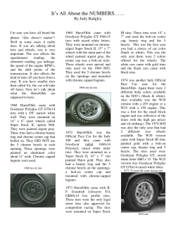


© Copyright 2026