
IBM Flex System Products and Technology for Power Systems Front cover
Front cover Draft Document for Review November 3, 2014 4:16 pm SG24-8256-00 IBM Flex System Products and Technology for Power Systems Covers both IBM Flex System and IBM PureFlex System offerings Describes the Power Systems servers and options available from IBM Provides details about the chassis, servers, networking and storage components David Watts Alexander Grechnev Dave Ridley ibm.com/redbooks Draft Document for Review November 3, 2014 4:16 pm 8256edno.fm International Technical Support Organization IBM Flex System Products and Technology for Power Systems November 2014 SG24-8256-00 8256edno.fm Draft Document for Review November 3, 2014 4:16 pm Note: Before using this information and the product it supports, read the information in “Notices” on page ix. First Edition (November 2014) This edition applies: IBM PureFlex System IBM Flex System Enterprise Chassis IBM Flex System Manager IBM Flex System p260 Compute Node IBM Flex System p270 Compute Node IBM Flex System p460 Compute Node IBM Flex System x240 Compute Node BM Flex System V7000 Storage Node IBM 42U 1100mm Enterprise V2 Dynamic Rack IBM PureFlex System 42U Rack and 42U Expansion Rack © Copyright International Business Machines Corporation 2014. All rights reserved. Note to U.S. Government Users Restricted Rights -- Use, duplication or disclosure restricted by GSA ADP Schedule Contract with IBM Corp. Draft Document for Review November 3, 2014 4:16 pm 8256TOC.fm Contents Notices . . . . . . . . . . . . . . . . . . . . . . . . . . . . . . . . . . . . . . . . . . . . . . . . . . . . . . . . . . . . . . . . . ix Trademarks . . . . . . . . . . . . . . . . . . . . . . . . . . . . . . . . . . . . . . . . . . . . . . . . . . . . . . . . . . . . . . .x Preface . . . . . . . . . . . . . . . . . . . . . . . . . . . . . . . . . . . . . . . . . . . . . . . . . . . . . . . . . . . . . . . . . xi Authors . . . . . . . . . . . . . . . . . . . . . . . . . . . . . . . . . . . . . . . . . . . . . . . . . . . . . . . . . . . . . . . . . . xii Now you can become a published author, too! . . . . . . . . . . . . . . . . . . . . . . . . . . . . . . . . . . xiii Comments welcome. . . . . . . . . . . . . . . . . . . . . . . . . . . . . . . . . . . . . . . . . . . . . . . . . . . . . . . xiii Stay connected to IBM Redbooks . . . . . . . . . . . . . . . . . . . . . . . . . . . . . . . . . . . . . . . . . . . . xiii Summary of changes . . . . . . . . . . . . . . . . . . . . . . . . . . . . . . . . . . . . . . . . . . . . . . . . . . . . . . xv November 2014, First Edition. . . . . . . . . . . . . . . . . . . . . . . . . . . . . . . . . . . . . . . . . . . . . . . . .xv Chapter 1. Introduction. . . . . . . . . . . . . . . . . . . . . . . . . . . . . . . . . . . . . . . . . . . . . . . . . . . . 1.1 IBM PureFlex System . . . . . . . . . . . . . . . . . . . . . . . . . . . . . . . . . . . . . . . . . . . . . . . . . . . 1.2 IBM Flex System overview . . . . . . . . . . . . . . . . . . . . . . . . . . . . . . . . . . . . . . . . . . . . . . . 1.2.1 IBM Flex System Manager . . . . . . . . . . . . . . . . . . . . . . . . . . . . . . . . . . . . . . . . . . . 1.2.2 IBM Flex System Enterprise Chassis . . . . . . . . . . . . . . . . . . . . . . . . . . . . . . . . . . . 1.2.3 Compute nodes. . . . . . . . . . . . . . . . . . . . . . . . . . . . . . . . . . . . . . . . . . . . . . . . . . . . 1.2.4 Storage nodes. . . . . . . . . . . . . . . . . . . . . . . . . . . . . . . . . . . . . . . . . . . . . . . . . . . . . 1.2.5 I/O modules. . . . . . . . . . . . . . . . . . . . . . . . . . . . . . . . . . . . . . . . . . . . . . . . . . . . . . . 1.3 This book. . . . . . . . . . . . . . . . . . . . . . . . . . . . . . . . . . . . . . . . . . . . . . . . . . . . . . . . . . . . . 1 2 4 4 5 6 7 8 8 Chapter 2. IBM PureFlex System . . . . . . . . . . . . . . . . . . . . . . . . . . . . . . . . . . . . . . . . . . . 2.1 Introduction . . . . . . . . . . . . . . . . . . . . . . . . . . . . . . . . . . . . . . . . . . . . . . . . . . . . . . . . . . 2.2 Routes to market . . . . . . . . . . . . . . . . . . . . . . . . . . . . . . . . . . . . . . . . . . . . . . . . . . . . . . 2.3 Components . . . . . . . . . . . . . . . . . . . . . . . . . . . . . . . . . . . . . . . . . . . . . . . . . . . . . . . . . 2.3.1 Configuring and ordering the IBM PureFlex System. . . . . . . . . . . . . . . . . . . . . . . 2.4 IBM PureFlex System Offering . . . . . . . . . . . . . . . . . . . . . . . . . . . . . . . . . . . . . . . . . . . 2.4.1 Available configurations . . . . . . . . . . . . . . . . . . . . . . . . . . . . . . . . . . . . . . . . . . . . 2.4.2 Chassis . . . . . . . . . . . . . . . . . . . . . . . . . . . . . . . . . . . . . . . . . . . . . . . . . . . . . . . . . 2.4.3 Compute nodes. . . . . . . . . . . . . . . . . . . . . . . . . . . . . . . . . . . . . . . . . . . . . . . . . . . 2.4.4 IBM Flex System Manager . . . . . . . . . . . . . . . . . . . . . . . . . . . . . . . . . . . . . . . . . . 2.4.5 PureFlex storage requirements and options . . . . . . . . . . . . . . . . . . . . . . . . . . . . . 2.4.6 Rack cabinet . . . . . . . . . . . . . . . . . . . . . . . . . . . . . . . . . . . . . . . . . . . . . . . . . . . . . 2.4.7 Available software for Power Systems compute nodes . . . . . . . . . . . . . . . . . . . . 2.4.8 Available software for x240 node . . . . . . . . . . . . . . . . . . . . . . . . . . . . . . . . . . . . . 2.5 Services for IBM PureFlex System . . . . . . . . . . . . . . . . . . . . . . . . . . . . . . . . . . . . . . . . 2.5.1 PureFlex FCoE Customization Service. . . . . . . . . . . . . . . . . . . . . . . . . . . . . . . . . 2.5.2 Software and hardware maintenance . . . . . . . . . . . . . . . . . . . . . . . . . . . . . . . . . . 2.6 IBM Cloud Manager with OpenStack . . . . . . . . . . . . . . . . . . . . . . . . . . . . . . . . . . . . . . 11 12 12 12 13 14 14 15 15 16 16 17 18 19 19 20 21 21 Chapter 3. Chassis and infrastructure configuration . . . . . . . . . . . . . . . . . . . . . . . . . . 3.1 Overview . . . . . . . . . . . . . . . . . . . . . . . . . . . . . . . . . . . . . . . . . . . . . . . . . . . . . . . . . . . . 3.1.1 Front of the chassis. . . . . . . . . . . . . . . . . . . . . . . . . . . . . . . . . . . . . . . . . . . . . . . . 3.1.2 Midplane . . . . . . . . . . . . . . . . . . . . . . . . . . . . . . . . . . . . . . . . . . . . . . . . . . . . . . . . 3.1.3 Rear of the chassis . . . . . . . . . . . . . . . . . . . . . . . . . . . . . . . . . . . . . . . . . . . . . . . . 3.1.4 Specifications . . . . . . . . . . . . . . . . . . . . . . . . . . . . . . . . . . . . . . . . . . . . . . . . . . . . 3.1.5 Compute node shelves . . . . . . . . . . . . . . . . . . . . . . . . . . . . . . . . . . . . . . . . . . . . . 3.1.6 Hot plug and hot swap components . . . . . . . . . . . . . . . . . . . . . . . . . . . . . . . . . . . 23 24 27 28 29 29 31 31 © Copyright IBM Corp. 2014. All rights reserved. iii 8256TOC.fm Draft Document for Review November 3, 2014 4:16 pm 3.2 3.3 3.4 3.5 3.6 3.7 Power supplies . . . . . . . . . . . . . . . . . . . . . . . . . . . . . . . . . . . . . . . . . . . . . . . . . . . . . . . Fan modules . . . . . . . . . . . . . . . . . . . . . . . . . . . . . . . . . . . . . . . . . . . . . . . . . . . . . . . . . Fan logic module . . . . . . . . . . . . . . . . . . . . . . . . . . . . . . . . . . . . . . . . . . . . . . . . . . . . . . Front information panel . . . . . . . . . . . . . . . . . . . . . . . . . . . . . . . . . . . . . . . . . . . . . . . . . Cooling . . . . . . . . . . . . . . . . . . . . . . . . . . . . . . . . . . . . . . . . . . . . . . . . . . . . . . . . . . . . . Power supply selection . . . . . . . . . . . . . . . . . . . . . . . . . . . . . . . . . . . . . . . . . . . . . . . . . 3.7.1 Power policies . . . . . . . . . . . . . . . . . . . . . . . . . . . . . . . . . . . . . . . . . . . . . . . . . . . . 3.7.2 Number of power supplies that are required for N+N and N+1. . . . . . . . . . . . . . . 3.8 Fan module population . . . . . . . . . . . . . . . . . . . . . . . . . . . . . . . . . . . . . . . . . . . . . . . . . 3.9 Chassis Management Module. . . . . . . . . . . . . . . . . . . . . . . . . . . . . . . . . . . . . . . . . . . . 3.10 Infrastructure planning . . . . . . . . . . . . . . . . . . . . . . . . . . . . . . . . . . . . . . . . . . . . . . . . 3.10.1 Supported power cords . . . . . . . . . . . . . . . . . . . . . . . . . . . . . . . . . . . . . . . . . . . . 3.10.2 DC power planning . . . . . . . . . . . . . . . . . . . . . . . . . . . . . . . . . . . . . . . . . . . . . . . 3.10.3 Console planning . . . . . . . . . . . . . . . . . . . . . . . . . . . . . . . . . . . . . . . . . . . . . . . . 3.10.4 Cooling planning . . . . . . . . . . . . . . . . . . . . . . . . . . . . . . . . . . . . . . . . . . . . . . . . . 3.10.5 Chassis-rack cabinet compatibility . . . . . . . . . . . . . . . . . . . . . . . . . . . . . . . . . . . 3.11 IBM PureFlex System 42U Rack . . . . . . . . . . . . . . . . . . . . . . . . . . . . . . . . . . . . . . . . 3.12 IBM Rear Door Heat eXchanger 1164-95X. . . . . . . . . . . . . . . . . . . . . . . . . . . . . . . . . 32 36 39 40 41 46 47 48 50 52 54 55 55 57 57 58 60 62 Chapter 4. Systems management . . . . . . . . . . . . . . . . . . . . . . . . . . . . . . . . . . . . . . . . . . 4.1 Management network . . . . . . . . . . . . . . . . . . . . . . . . . . . . . . . . . . . . . . . . . . . . . . . . . . 4.2 Chassis Management Module. . . . . . . . . . . . . . . . . . . . . . . . . . . . . . . . . . . . . . . . . . . . 4.2.1 Overview . . . . . . . . . . . . . . . . . . . . . . . . . . . . . . . . . . . . . . . . . . . . . . . . . . . . . . . . 4.2.2 Interfaces . . . . . . . . . . . . . . . . . . . . . . . . . . . . . . . . . . . . . . . . . . . . . . . . . . . . . . . 4.3 Security . . . . . . . . . . . . . . . . . . . . . . . . . . . . . . . . . . . . . . . . . . . . . . . . . . . . . . . . . . . . . 4.4 Compute node management. . . . . . . . . . . . . . . . . . . . . . . . . . . . . . . . . . . . . . . . . . . . . 4.4.1 Integrated Management Module II . . . . . . . . . . . . . . . . . . . . . . . . . . . . . . . . . . . . 4.4.2 Flexible service processor. . . . . . . . . . . . . . . . . . . . . . . . . . . . . . . . . . . . . . . . . . . 4.4.3 I/O modules. . . . . . . . . . . . . . . . . . . . . . . . . . . . . . . . . . . . . . . . . . . . . . . . . . . . . . 4.5 IBM Flex System Manager . . . . . . . . . . . . . . . . . . . . . . . . . . . . . . . . . . . . . . . . . . . . . . 4.5.1 IBM Flex System Manager functions and licensing . . . . . . . . . . . . . . . . . . . . . . . 4.5.2 Hardware overview . . . . . . . . . . . . . . . . . . . . . . . . . . . . . . . . . . . . . . . . . . . . . . . . 4.5.3 Software features . . . . . . . . . . . . . . . . . . . . . . . . . . . . . . . . . . . . . . . . . . . . . . . . . 4.5.4 User interfaces . . . . . . . . . . . . . . . . . . . . . . . . . . . . . . . . . . . . . . . . . . . . . . . . . . . 4.5.5 Mobile System Management application . . . . . . . . . . . . . . . . . . . . . . . . . . . . . . . 4.5.6 Flex System Manager CLI. . . . . . . . . . . . . . . . . . . . . . . . . . . . . . . . . . . . . . . . . . . 4.5.7 Backup of the Flex System Manager software . . . . . . . . . . . . . . . . . . . . . . . . . . . 67 68 69 69 70 72 73 73 74 75 76 76 78 82 89 90 91 91 Chapter 5. I/O architecture and components . . . . . . . . . . . . . . . . . . . . . . . . . . . . . . . . . 93 5.1 I/O architecture . . . . . . . . . . . . . . . . . . . . . . . . . . . . . . . . . . . . . . . . . . . . . . . . . . . . . . . 94 5.2 I/O modules . . . . . . . . . . . . . . . . . . . . . . . . . . . . . . . . . . . . . . . . . . . . . . . . . . . . . . . . . 102 5.2.1 I/O module LEDs. . . . . . . . . . . . . . . . . . . . . . . . . . . . . . . . . . . . . . . . . . . . . . . . . 103 5.2.2 Serial access cable . . . . . . . . . . . . . . . . . . . . . . . . . . . . . . . . . . . . . . . . . . . . . . . 103 5.2.3 I/O module naming scheme . . . . . . . . . . . . . . . . . . . . . . . . . . . . . . . . . . . . . . . . 104 5.2.4 Switch to adapter compatibility . . . . . . . . . . . . . . . . . . . . . . . . . . . . . . . . . . . . . . 104 5.2.5 IBM Flex System EN6131 40Gb Ethernet Switch . . . . . . . . . . . . . . . . . . . . . . . . 107 5.2.6 IBM Flex System Fabric CN4093 10Gb Converged Scalable Switch . . . . . . . . . 111 5.2.7 IBM Flex System Fabric EN4093R 10Gb Scalable Switch . . . . . . . . . . . . . . . . . 121 5.2.8 IBM Flex System Fabric SI4093 System Interconnect Module . . . . . . . . . . . . . . 128 5.2.9 IBM Flex System EN4023 10Gb Scalable Switch. . . . . . . . . . . . . . . . . . . . . . . . 135 5.2.10 IBM Flex System EN4091 10Gb Ethernet Pass-thru Module . . . . . . . . . . . . . . 141 5.2.11 Cisco Nexus B22 Fabric Extender for IBM Flex System. . . . . . . . . . . . . . . . . . 143 5.2.12 IBM Flex System EN2092 1Gb Ethernet Scalable Switch . . . . . . . . . . . . . . . . 148 iv IBM Flex System Products and Technology for Power Systems Draft Document for Review November 3, 2014 4:16 pm 8256TOC.fm 5.2.13 IBM Flex System FC5022 16Gb SAN Scalable Switch. . . . . . . . . . . . . . . . . . . 5.2.14 IBM Flex System FC3171 8Gb SAN Switch . . . . . . . . . . . . . . . . . . . . . . . . . . . 5.2.15 IBM Flex System FC3171 8Gb SAN Pass-thru. . . . . . . . . . . . . . . . . . . . . . . . . 5.2.16 IBM Flex System IB6131 InfiniBand Switch . . . . . . . . . . . . . . . . . . . . . . . . . . . 5.3 I/O adapters . . . . . . . . . . . . . . . . . . . . . . . . . . . . . . . . . . . . . . . . . . . . . . . . . . . . . . . . 5.3.1 Form factor . . . . . . . . . . . . . . . . . . . . . . . . . . . . . . . . . . . . . . . . . . . . . . . . . . . . . 5.3.2 Naming structure. . . . . . . . . . . . . . . . . . . . . . . . . . . . . . . . . . . . . . . . . . . . . . . . . 5.3.3 Supported compute nodes . . . . . . . . . . . . . . . . . . . . . . . . . . . . . . . . . . . . . . . . . 5.3.4 Supported switches. . . . . . . . . . . . . . . . . . . . . . . . . . . . . . . . . . . . . . . . . . . . . . . 5.3.5 IBM Flex System EN2024 4-port 1Gb Ethernet Adapter. . . . . . . . . . . . . . . . . . . 5.3.6 IBM Flex System EN4132 2-port 10Gb Ethernet Adapter. . . . . . . . . . . . . . . . . . 5.3.7 IBM Flex System EN4054 4-port 10Gb Ethernet Adapter. . . . . . . . . . . . . . . . . . 5.3.8 IBM Flex System EN6132 2-port 40Gb Ethernet Adapter. . . . . . . . . . . . . . . . . . 5.3.9 IBM Flex System CN4022 2-port 10Gb Converged Adapter . . . . . . . . . . . . . . . 5.3.10 IBM Flex System CN4054R 10 Gb Virtual Fabric Adapter . . . . . . . . . . . . . . . . 5.3.11 IBM Flex System CN4058 8-port 10Gb Converged Adapter . . . . . . . . . . . . . . 5.3.12 IBM Flex System EN4132 2-port 10Gb RoCE Adapter. . . . . . . . . . . . . . . . . . . 5.3.13 IBM Flex System FC3172 2-port 8Gb FC Adapter . . . . . . . . . . . . . . . . . . . . . . 5.3.14 IBM Flex System FC3052 2-port 8Gb FC Adapter . . . . . . . . . . . . . . . . . . . . . . 5.3.15 IBM Flex System FC5022 2-port 16Gb FC Adapter . . . . . . . . . . . . . . . . . . . . . 5.3.16 IBM Flex System FC5052 2-port and FC5054 4-port 16Gb FC Adapters. . . . . 5.3.17 IBM Flex System IB6132 2-port QDR InfiniBand Adapter. . . . . . . . . . . . . . . . . 154 161 163 165 167 168 168 169 170 171 173 174 176 177 180 183 185 187 188 190 191 194 Chapter 6. Compute nodes . . . . . . . . . . . . . . . . . . . . . . . . . . . . . . . . . . . . . . . . . . . . . . 6.1 IBM Flex System p260 Compute Node . . . . . . . . . . . . . . . . . . . . . . . . . . . . . . . . . . . . 6.1.1 Specifications . . . . . . . . . . . . . . . . . . . . . . . . . . . . . . . . . . . . . . . . . . . . . . . . . . . 6.1.2 System board layout . . . . . . . . . . . . . . . . . . . . . . . . . . . . . . . . . . . . . . . . . . . . . . 6.1.3 Front panel . . . . . . . . . . . . . . . . . . . . . . . . . . . . . . . . . . . . . . . . . . . . . . . . . . . . . 6.1.4 Chassis support . . . . . . . . . . . . . . . . . . . . . . . . . . . . . . . . . . . . . . . . . . . . . . . . . 6.1.5 System architecture . . . . . . . . . . . . . . . . . . . . . . . . . . . . . . . . . . . . . . . . . . . . . . 6.1.6 Processor . . . . . . . . . . . . . . . . . . . . . . . . . . . . . . . . . . . . . . . . . . . . . . . . . . . . . . 6.1.7 Memory . . . . . . . . . . . . . . . . . . . . . . . . . . . . . . . . . . . . . . . . . . . . . . . . . . . . . . . . 6.1.8 Active Memory Expansion. . . . . . . . . . . . . . . . . . . . . . . . . . . . . . . . . . . . . . . . . . 6.1.9 Storage . . . . . . . . . . . . . . . . . . . . . . . . . . . . . . . . . . . . . . . . . . . . . . . . . . . . . . . . 6.1.10 I/O expansion . . . . . . . . . . . . . . . . . . . . . . . . . . . . . . . . . . . . . . . . . . . . . . . . . . 6.1.11 System management . . . . . . . . . . . . . . . . . . . . . . . . . . . . . . . . . . . . . . . . . . . . 6.1.12 Operating system support . . . . . . . . . . . . . . . . . . . . . . . . . . . . . . . . . . . . . . . . . 6.2 IBM Flex System p270 Compute Node . . . . . . . . . . . . . . . . . . . . . . . . . . . . . . . . . . . . 6.2.1 Specifications . . . . . . . . . . . . . . . . . . . . . . . . . . . . . . . . . . . . . . . . . . . . . . . . . . . 6.2.2 System board layout . . . . . . . . . . . . . . . . . . . . . . . . . . . . . . . . . . . . . . . . . . . . . . 6.2.3 Comparing the p260 and p270 . . . . . . . . . . . . . . . . . . . . . . . . . . . . . . . . . . . . . . 6.2.4 Front panel . . . . . . . . . . . . . . . . . . . . . . . . . . . . . . . . . . . . . . . . . . . . . . . . . . . . . 6.2.5 Chassis support . . . . . . . . . . . . . . . . . . . . . . . . . . . . . . . . . . . . . . . . . . . . . . . . . 6.2.6 System architecture . . . . . . . . . . . . . . . . . . . . . . . . . . . . . . . . . . . . . . . . . . . . . . 6.2.7 IBM POWER7+ processor . . . . . . . . . . . . . . . . . . . . . . . . . . . . . . . . . . . . . . . . . 6.2.8 Memory subsystem . . . . . . . . . . . . . . . . . . . . . . . . . . . . . . . . . . . . . . . . . . . . . . . 6.2.9 Active Memory Expansion feature . . . . . . . . . . . . . . . . . . . . . . . . . . . . . . . . . . . 6.2.10 Storage . . . . . . . . . . . . . . . . . . . . . . . . . . . . . . . . . . . . . . . . . . . . . . . . . . . . . . . 6.2.11 I/O expansion . . . . . . . . . . . . . . . . . . . . . . . . . . . . . . . . . . . . . . . . . . . . . . . . . . 6.2.12 System management . . . . . . . . . . . . . . . . . . . . . . . . . . . . . . . . . . . . . . . . . . . . 6.2.13 Operating system support . . . . . . . . . . . . . . . . . . . . . . . . . . . . . . . . . . . . . . . . . 6.3 IBM Flex System p460 Compute Node . . . . . . . . . . . . . . . . . . . . . . . . . . . . . . . . . . . . 6.3.1 Overview . . . . . . . . . . . . . . . . . . . . . . . . . . . . . . . . . . . . . . . . . . . . . . . . . . . . . . . 197 198 198 200 200 203 203 204 207 209 212 214 215 216 218 218 220 221 221 223 224 224 227 229 229 233 234 234 235 236 Contents v 8256TOC.fm vi Draft Document for Review November 3, 2014 4:16 pm 6.3.2 System board layout . . . . . . . . . . . . . . . . . . . . . . . . . . . . . . . . . . . . . . . . . . . . . . 6.3.3 Front panel . . . . . . . . . . . . . . . . . . . . . . . . . . . . . . . . . . . . . . . . . . . . . . . . . . . . . 6.3.4 Chassis support . . . . . . . . . . . . . . . . . . . . . . . . . . . . . . . . . . . . . . . . . . . . . . . . . 6.3.5 System architecture . . . . . . . . . . . . . . . . . . . . . . . . . . . . . . . . . . . . . . . . . . . . . . 6.3.6 Processor . . . . . . . . . . . . . . . . . . . . . . . . . . . . . . . . . . . . . . . . . . . . . . . . . . . . . . 6.3.7 Memory . . . . . . . . . . . . . . . . . . . . . . . . . . . . . . . . . . . . . . . . . . . . . . . . . . . . . . . . 6.3.8 Active Memory Expansion feature . . . . . . . . . . . . . . . . . . . . . . . . . . . . . . . . . . . 6.3.9 Storage . . . . . . . . . . . . . . . . . . . . . . . . . . . . . . . . . . . . . . . . . . . . . . . . . . . . . . . . 6.3.10 Local storage and cover options . . . . . . . . . . . . . . . . . . . . . . . . . . . . . . . . . . . . 6.3.11 Hardware RAID capabilities . . . . . . . . . . . . . . . . . . . . . . . . . . . . . . . . . . . . . . . 6.3.12 I/O expansion . . . . . . . . . . . . . . . . . . . . . . . . . . . . . . . . . . . . . . . . . . . . . . . . . . 6.3.13 System management . . . . . . . . . . . . . . . . . . . . . . . . . . . . . . . . . . . . . . . . . . . . 6.3.14 Integrated features . . . . . . . . . . . . . . . . . . . . . . . . . . . . . . . . . . . . . . . . . . . . . . 6.3.15 Operating system support . . . . . . . . . . . . . . . . . . . . . . . . . . . . . . . . . . . . . . . . . 6.4 IBM Flex System x240 Compute Node . . . . . . . . . . . . . . . . . . . . . . . . . . . . . . . . . . . . 6.4.1 Introduction . . . . . . . . . . . . . . . . . . . . . . . . . . . . . . . . . . . . . . . . . . . . . . . . . . . . . 6.4.2 Specifications . . . . . . . . . . . . . . . . . . . . . . . . . . . . . . . . . . . . . . . . . . . . . . . . . . . 6.4.3 Chassis support . . . . . . . . . . . . . . . . . . . . . . . . . . . . . . . . . . . . . . . . . . . . . . . . . 6.4.4 System architecture . . . . . . . . . . . . . . . . . . . . . . . . . . . . . . . . . . . . . . . . . . . . . . 6.4.5 Processor . . . . . . . . . . . . . . . . . . . . . . . . . . . . . . . . . . . . . . . . . . . . . . . . . . . . . . 6.4.6 Memory . . . . . . . . . . . . . . . . . . . . . . . . . . . . . . . . . . . . . . . . . . . . . . . . . . . . . . . . 6.4.7 Standard onboard features . . . . . . . . . . . . . . . . . . . . . . . . . . . . . . . . . . . . . . . . . 6.4.8 Local storage . . . . . . . . . . . . . . . . . . . . . . . . . . . . . . . . . . . . . . . . . . . . . . . . . . . 6.4.9 Integrated virtualization . . . . . . . . . . . . . . . . . . . . . . . . . . . . . . . . . . . . . . . . . . . . 6.4.10 Embedded 10 Gb Virtual Fabric adapter. . . . . . . . . . . . . . . . . . . . . . . . . . . . . . 6.4.11 I/O expansion . . . . . . . . . . . . . . . . . . . . . . . . . . . . . . . . . . . . . . . . . . . . . . . . . . 6.4.12 Systems management . . . . . . . . . . . . . . . . . . . . . . . . . . . . . . . . . . . . . . . . . . . 6.4.13 Operating system support . . . . . . . . . . . . . . . . . . . . . . . . . . . . . . . . . . . . . . . . . 238 238 240 241 242 245 248 249 250 252 252 253 254 254 255 255 257 259 260 262 263 276 277 280 281 282 284 287 Chapter 7. Network integration . . . . . . . . . . . . . . . . . . . . . . . . . . . . . . . . . . . . . . . . . . . 7.1 Choosing the Ethernet switch I/O module . . . . . . . . . . . . . . . . . . . . . . . . . . . . . . . . . . 7.2 Virtual local area networks . . . . . . . . . . . . . . . . . . . . . . . . . . . . . . . . . . . . . . . . . . . . . 7.3 Scalability and port flexibility . . . . . . . . . . . . . . . . . . . . . . . . . . . . . . . . . . . . . . . . . . . . 7.4 IBM Flex System Interconnect Fabric . . . . . . . . . . . . . . . . . . . . . . . . . . . . . . . . . . . . . 7.5 High Availability . . . . . . . . . . . . . . . . . . . . . . . . . . . . . . . . . . . . . . . . . . . . . . . . . . . . . . 7.5.1 Highly available topologies . . . . . . . . . . . . . . . . . . . . . . . . . . . . . . . . . . . . . . . . . 7.5.2 Spanning Tree . . . . . . . . . . . . . . . . . . . . . . . . . . . . . . . . . . . . . . . . . . . . . . . . . . 7.5.3 Link aggregation . . . . . . . . . . . . . . . . . . . . . . . . . . . . . . . . . . . . . . . . . . . . . . . . . 7.5.4 NIC teaming . . . . . . . . . . . . . . . . . . . . . . . . . . . . . . . . . . . . . . . . . . . . . . . . . . . . 7.5.5 Trunk failover . . . . . . . . . . . . . . . . . . . . . . . . . . . . . . . . . . . . . . . . . . . . . . . . . . . 7.5.6 Virtual Router Redundancy Protocol. . . . . . . . . . . . . . . . . . . . . . . . . . . . . . . . . . 7.6 FCoE capabilities . . . . . . . . . . . . . . . . . . . . . . . . . . . . . . . . . . . . . . . . . . . . . . . . . . . . 7.7 vNIC solution capabilities . . . . . . . . . . . . . . . . . . . . . . . . . . . . . . . . . . . . . . . . . . . . . . 7.7.1 Virtual Fabric mode vNIC . . . . . . . . . . . . . . . . . . . . . . . . . . . . . . . . . . . . . . . . . . 7.7.2 Switch-independent mode vNIC . . . . . . . . . . . . . . . . . . . . . . . . . . . . . . . . . . . . . 7.8 Unified Fabric Port feature . . . . . . . . . . . . . . . . . . . . . . . . . . . . . . . . . . . . . . . . . . . . . 7.9 Easy Connect concept . . . . . . . . . . . . . . . . . . . . . . . . . . . . . . . . . . . . . . . . . . . . . . . . 7.10 Stacking feature . . . . . . . . . . . . . . . . . . . . . . . . . . . . . . . . . . . . . . . . . . . . . . . . . . . . 7.11 OpenFlow support . . . . . . . . . . . . . . . . . . . . . . . . . . . . . . . . . . . . . . . . . . . . . . . . . . . 7.12 802.1Qbg Edge Virtual Bridge support . . . . . . . . . . . . . . . . . . . . . . . . . . . . . . . . . . . 7.13 SPAR feature . . . . . . . . . . . . . . . . . . . . . . . . . . . . . . . . . . . . . . . . . . . . . . . . . . . . . . 7.14 Management . . . . . . . . . . . . . . . . . . . . . . . . . . . . . . . . . . . . . . . . . . . . . . . . . . . . . . . 7.14.1 Management tools and their capabilities. . . . . . . . . . . . . . . . . . . . . . . . . . . . . . 289 290 292 294 297 299 301 304 305 307 308 309 310 311 312 314 315 317 319 320 321 322 323 324 IBM Flex System Products and Technology for Power Systems Draft Document for Review November 3, 2014 4:16 pm 8256TOC.fm 7.15 Summary and conclusions . . . . . . . . . . . . . . . . . . . . . . . . . . . . . . . . . . . . . . . . . . . . 325 Chapter 8. Storage integration. . . . . . . . . . . . . . . . . . . . . . . . . . . . . . . . . . . . . . . . . . . . 8.1 IBM Flex System V7000 Storage Node . . . . . . . . . . . . . . . . . . . . . . . . . . . . . . . . . . . 8.1.1 V7000 Storage Node types . . . . . . . . . . . . . . . . . . . . . . . . . . . . . . . . . . . . . . . . . 8.1.2 Controller Modules . . . . . . . . . . . . . . . . . . . . . . . . . . . . . . . . . . . . . . . . . . . . . . . 8.1.3 Expansion Modules. . . . . . . . . . . . . . . . . . . . . . . . . . . . . . . . . . . . . . . . . . . . . . . 8.1.4 SAS cabling . . . . . . . . . . . . . . . . . . . . . . . . . . . . . . . . . . . . . . . . . . . . . . . . . . . . 8.1.5 Host interface cards . . . . . . . . . . . . . . . . . . . . . . . . . . . . . . . . . . . . . . . . . . . . . . 8.1.6 Fibre Channel over Ethernet with a V7000 Storage Node . . . . . . . . . . . . . . . . . 8.1.7 V7000 Storage Node drive options . . . . . . . . . . . . . . . . . . . . . . . . . . . . . . . . . . . 8.1.8 Features and functions . . . . . . . . . . . . . . . . . . . . . . . . . . . . . . . . . . . . . . . . . . . . 8.1.9 Licenses . . . . . . . . . . . . . . . . . . . . . . . . . . . . . . . . . . . . . . . . . . . . . . . . . . . . . . . 8.1.10 Configuration restrictions . . . . . . . . . . . . . . . . . . . . . . . . . . . . . . . . . . . . . . . . . 8.2 External storage . . . . . . . . . . . . . . . . . . . . . . . . . . . . . . . . . . . . . . . . . . . . . . . . . . . . . 8.2.1 IBM Storwize V7000 . . . . . . . . . . . . . . . . . . . . . . . . . . . . . . . . . . . . . . . . . . . . . . 8.2.2 IBM XIV Storage System series . . . . . . . . . . . . . . . . . . . . . . . . . . . . . . . . . . . . . 8.2.3 IBM System Storage DS8000 series. . . . . . . . . . . . . . . . . . . . . . . . . . . . . . . . . . 8.2.4 IBM Storwize V3700 Storage System . . . . . . . . . . . . . . . . . . . . . . . . . . . . . . . . . 8.2.5 IBM System Storage DS3500 series. . . . . . . . . . . . . . . . . . . . . . . . . . . . . . . . . . 8.2.6 IBM network-attached storage products . . . . . . . . . . . . . . . . . . . . . . . . . . . . . . . 8.2.7 IBM FlashSystem . . . . . . . . . . . . . . . . . . . . . . . . . . . . . . . . . . . . . . . . . . . . . . . . 8.2.8 IBM System Storage TS3500 Tape Library . . . . . . . . . . . . . . . . . . . . . . . . . . . . 8.2.9 IBM System Storage TS3310 series . . . . . . . . . . . . . . . . . . . . . . . . . . . . . . . . . . 8.2.10 IBM System Storage TS3200 Tape Library . . . . . . . . . . . . . . . . . . . . . . . . . . . 8.2.11 IBM System Storage TS3100 Tape Library . . . . . . . . . . . . . . . . . . . . . . . . . . . 8.2.12 IBM System Storage TS2900 Tape Autoloader . . . . . . . . . . . . . . . . . . . . . . . . 8.3 Fibre Channel . . . . . . . . . . . . . . . . . . . . . . . . . . . . . . . . . . . . . . . . . . . . . . . . . . . . . . . 8.3.1 FC requirements . . . . . . . . . . . . . . . . . . . . . . . . . . . . . . . . . . . . . . . . . . . . . . . . . 8.3.2 FC switch selection and fabric interoperability rules . . . . . . . . . . . . . . . . . . . . . . 8.4 FCoE . . . . . . . . . . . . . . . . . . . . . . . . . . . . . . . . . . . . . . . . . . . . . . . . . . . . . . . . . . . . . . 8.5 iSCSI . . . . . . . . . . . . . . . . . . . . . . . . . . . . . . . . . . . . . . . . . . . . . . . . . . . . . . . . . . . . . . 8.6 HA and redundancy . . . . . . . . . . . . . . . . . . . . . . . . . . . . . . . . . . . . . . . . . . . . . . . . . . 8.7 Performance . . . . . . . . . . . . . . . . . . . . . . . . . . . . . . . . . . . . . . . . . . . . . . . . . . . . . . . . 8.8 Backup solutions . . . . . . . . . . . . . . . . . . . . . . . . . . . . . . . . . . . . . . . . . . . . . . . . . . . . . 8.8.1 Dedicated server for centralized LAN backup. . . . . . . . . . . . . . . . . . . . . . . . . . . 8.8.2 LAN-free backup for nodes . . . . . . . . . . . . . . . . . . . . . . . . . . . . . . . . . . . . . . . . . 8.9 Boot from SAN . . . . . . . . . . . . . . . . . . . . . . . . . . . . . . . . . . . . . . . . . . . . . . . . . . . . . . 327 328 332 333 338 340 342 342 343 343 345 347 347 349 350 351 351 352 353 353 354 354 355 355 356 357 357 357 361 362 363 365 365 366 367 368 Abbreviations and acronyms . . . . . . . . . . . . . . . . . . . . . . . . . . . . . . . . . . . . . . . . . . . . . 369 Related publications . . . . . . . . . . . . . . . . . . . . . . . . . . . . . . . . . . . . . . . . . . . . . . . . . . . . IBM Redbooks . . . . . . . . . . . . . . . . . . . . . . . . . . . . . . . . . . . . . . . . . . . . . . . . . . . . . . . . . . Online resources . . . . . . . . . . . . . . . . . . . . . . . . . . . . . . . . . . . . . . . . . . . . . . . . . . . . . . . . Help from IBM . . . . . . . . . . . . . . . . . . . . . . . . . . . . . . . . . . . . . . . . . . . . . . . . . . . . . . . . . . Contents 371 371 372 372 vii 8256TOC.fm viii Draft Document for Review November 3, 2014 4:16 pm IBM Flex System Products and Technology for Power Systems Draft Document for Review November 3, 2014 4:16 pm 8256spec.fm Notices This information was developed for products and services offered in the U.S.A. IBM may not offer the products, services, or features discussed in this document in other countries. Consult your local IBM representative for information on the products and services currently available in your area. Any reference to an IBM product, program, or service is not intended to state or imply that only that IBM product, program, or service may be used. Any functionally equivalent product, program, or service that does not infringe any IBM intellectual property right may be used instead. However, it is the user's responsibility to evaluate and verify the operation of any non-IBM product, program, or service. IBM may have patents or pending patent applications covering subject matter described in this document. The furnishing of this document does not grant you any license to these patents. You can send license inquiries, in writing, to: IBM Director of Licensing, IBM Corporation, North Castle Drive, Armonk, NY 10504-1785 U.S.A. The following paragraph does not apply to the United Kingdom or any other country where such provisions are inconsistent with local law: INTERNATIONAL BUSINESS MACHINES CORPORATION PROVIDES THIS PUBLICATION "AS IS" WITHOUT WARRANTY OF ANY KIND, EITHER EXPRESS OR IMPLIED, INCLUDING, BUT NOT LIMITED TO, THE IMPLIED WARRANTIES OF NON-INFRINGEMENT, MERCHANTABILITY OR FITNESS FOR A PARTICULAR PURPOSE. Some states do not allow disclaimer of express or implied warranties in certain transactions, therefore, this statement may not apply to you. This information could include technical inaccuracies or typographical errors. Changes are periodically made to the information herein; these changes will be incorporated in new editions of the publication. IBM may make improvements and/or changes in the product(s) and/or the program(s) described in this publication at any time without notice. Any references in this information to non-IBM websites are provided for convenience only and do not in any manner serve as an endorsement of those websites. The materials at those websites are not part of the materials for this IBM product and use of those websites is at your own risk. IBM may use or distribute any of the information you supply in any way it believes appropriate without incurring any obligation to you. Any performance data contained herein was determined in a controlled environment. Therefore, the results obtained in other operating environments may vary significantly. Some measurements may have been made on development-level systems and there is no guarantee that these measurements will be the same on generally available systems. Furthermore, some measurements may have been estimated through extrapolation. Actual results may vary. Users of this document should verify the applicable data for their specific environment. Information concerning non-IBM products was obtained from the suppliers of those products, their published announcements or other publicly available sources. IBM has not tested those products and cannot confirm the accuracy of performance, compatibility or any other claims related to non-IBM products. Questions on the capabilities of non-IBM products should be addressed to the suppliers of those products. This information contains examples of data and reports used in daily business operations. To illustrate them as completely as possible, the examples include the names of individuals, companies, brands, and products. All of these names are fictitious and any similarity to the names and addresses used by an actual business enterprise is entirely coincidental. COPYRIGHT LICENSE: This information contains sample application programs in source language, which illustrate programming techniques on various operating platforms. You may copy, modify, and distribute these sample programs in any form without payment to IBM, for the purposes of developing, using, marketing or distributing application programs conforming to the application programming interface for the operating platform for which the sample programs are written. These examples have not been thoroughly tested under all conditions. IBM, therefore, cannot guarantee or imply reliability, serviceability, or function of these programs. © Copyright IBM Corp. 2014. All rights reserved. ix 8256spec.fm Draft Document for Review November 3, 2014 4:16 pm Trademarks IBM, the IBM logo, and ibm.com are trademarks or registered trademarks of International Business Machines Corporation in the United States, other countries, or both. These and other IBM trademarked terms are marked on their first occurrence in this information with the appropriate symbol (® or ™), indicating US registered or common law trademarks owned by IBM at the time this information was published. Such trademarks may also be registered or common law trademarks in other countries. A current list of IBM trademarks is available on the Web at http://www.ibm.com/legal/copytrade.shtml The following terms are trademarks of the International Business Machines Corporation in the United States, other countries, or both: Active Cloud Engine® Active Memory™ AIX® AIX 5L™ DB2® DS8000® Easy Tier® eServer™ FICON® FlashCopy® FlashSystem™ IBM® IBM Flex System® IBM Flex System Manager® IBM PureData™ Linear Tape File System™ POWER® Power Systems™ POWER6® POWER6+™ POWER7® POWER7+™ PowerPC® PowerVM® PureApplication® PureData™ PureFlex® PureSystems® Real-time Compression™ Redbooks® Redbooks (logo) ® ServicePac® Storwize® System Storage® System Storage DS® Tivoli® Tivoli Storage Manager FastBack® XIV® The following terms are trademarks of other companies: Intel, Intel Xeon, Intel logo, Intel Inside logo, and Intel Centrino logo are trademarks or registered trademarks of Intel Corporation or its subsidiaries in the United States and other countries. Linux is a trademark of Linus Torvalds in the United States, other countries, or both. Linear Tape-Open, LTO, Ultrium, the LTO Logo and the Ultrium logo are trademarks of HP, IBM Corp. and Quantum in the U.S. and other countries. Microsoft, Windows, and the Windows logo are trademarks of Microsoft Corporation in the United States, other countries, or both. Java, and all Java-based trademarks and logos are trademarks or registered trademarks of Oracle and/or its affiliates. UNIX is a registered trademark of The Open Group in the United States and other countries. Other company, product, or service names may be trademarks or service marks of others. x IBM Flex System Products and Technology for Power Systems Draft Document for Review November 3, 2014 4:16 pm 8256pref.fm Preface To meet today’s complex and ever-changing business demands, you need a solid foundation of compute, storage, networking, and software resources. This system must be simple to deploy, and be able to quickly and automatically adapt to changing conditions. You also need to be able to take advantage of broad expertise and proven guidelines in systems management, applications, hardware maintenance, and more. The IBM® PureFlex® System combines no-compromise system designs along with built-in expertise and integrates them into complete, optimized solutions. At the heart of PureFlex System is the IBM Flex System® Enterprise Chassis. This fully integrated infrastructure platform supports a mix of compute, storage, and networking resources to meet the demands of your applications. The solution is easily scalable with the addition of another chassis with the required nodes. With the IBM Flex System Manager®, multiple chassis can be monitored from a single panel. The 14 node, 10U chassis delivers high-speed performance complete with integrated servers, storage, and networking. This flexible chassis is simple to deploy now, and to scale to meet your needs in the future. This IBM Redbooks® publication describes IBM PureFlex System and IBM Flex System available from IBM. It highlights the technology and features of the chassis, compute nodes, management features, and connectivity options. Guidance is provided about every major component, and about networking and storage connectivity. This book is intended for customers, IBM Business Partners, and IBM employees who want to know the details about the new family of products. It assumes that you have a basic understanding of blade server concepts and general IT knowledge. © Copyright IBM Corp. 2014. All rights reserved. xi 8256pref.fm Draft Document for Review November 3, 2014 4:16 pm Authors This book was produced by the following subject matter experts working in the Lenovo offices in Morrisville, NC, USA. David Watts is a Senior IT Consultant in the Lenovo Enterprise Business Group in Morrisville, North Carolina in the USA. He manages residencies and produces pre-sale and post-sale technical publications for hardware and software topics that are related to System x, Flex System, and BladeCenter servers. He has authored over 300 books and papers. Prior to working for Lenovo starting in 2014, David had worked for the IBM Redbooks organization (1997-2014) and as a pre-sale technical specialist for IBM Australia (1989-1996). David holds a Bachelor of Engineering degree from the University of Queensland (Australia). Alexander Grechnev is a Techline System x Specialist at IBM East Europe/Asia and has been with IBM since 2006. He is responsible for pre-sales technical support of IBM employees and IBM Business Partners, and specializes in System x and BladeCenter products. He graduated from the Moscow State Technical University n.a. Bauman in 2002. Dave Ridley is the PureFlex and Flex System Technical Product Manager for IBM in the United Kingdom and Ireland. His role includes product transition planning, supporting marketing events, press briefings, managing the UK loan pool, running early ship programs, and supporting the local sales and technical teams. He is based in Horsham in the United Kingdom, and has worked for IBM since 1998. In addition, he has been involved with IBM x86 products for 27 years. This book is a follow-on to IBM PureFlex System and IBM Flex System Products and Technology, SG24-7984. Thanks to the authors of all five editions of the book: Authors of the fifth edition of SG24-7984 were: David Watts Alexander Grechnev Dave Ridley Authors of the second, third, and fourth editions of SG24-7984 were: David Watts Randall Davis Dave Ridley xii IBM Flex System Products and Technology for Power Systems Draft Document for Review November 3, 2014 4:16 pm 8256pref.fm Authors of the first edition of SG24-7984, published in July 2012, were: David Watts Randall Davis Richard French Lu Han Dave Ridley Cristian Rojas The authors would like to dedicate this edition to our good friend and colleague Randall Davis, who passed away September 2014. Now you can become a published author, too! Here’s an opportunity to spotlight your skills, grow your career, and become a published author—all at the same time! Join an ITSO residency project and help write a book in your area of expertise, while honing your experience using leading-edge technologies. Your efforts will help to increase product acceptance and customer satisfaction, as you expand your network of technical contacts and relationships. Residencies run from two to six weeks in length, and you can participate either in person or as a remote resident working from your home base. Find out more about the residency program, browse the residency index, and apply online at: ibm.com/redbooks/residencies.html Comments welcome Your comments are important to us! We want our books to be as helpful as possible. Send us your comments about this book or other IBM Redbooks publications in one of the following ways: Use the online Contact us review Redbooks form found at: ibm.com/redbooks Send your comments in an email to: [email protected] Mail your comments to: IBM Corporation, International Technical Support Organization Dept. HYTD Mail Station P099 2455 South Road Poughkeepsie, NY 12601-5400 Stay connected to IBM Redbooks Find us on Facebook: http://www.facebook.com/IBMRedbooks Follow us on Twitter: http://twitter.com/ibmredbooks Preface xiii 8256pref.fm Draft Document for Review November 3, 2014 4:16 pm Look for us on LinkedIn: http://www.linkedin.com/groups?home=&gid=2130806 Explore new Redbooks publications, residencies, and workshops with the IBM Redbooks weekly newsletter: https://www.redbooks.ibm.com/Redbooks.nsf/subscribe?OpenForm Stay current on recent Redbooks publications with RSS Feeds: http://www.redbooks.ibm.com/rss.html xiv IBM Flex System Products and Technology for Power Systems Draft Document for Review November 3, 2014 4:16 pm 8256chang.fm Summary of changes This section describes the technical changes made in this edition of the book and in previous editions. This edition might also include minor corrections and editorial changes that are not identified. Summary of Changes for SG24-8256-00 for IBM Flex System Products and Technology for Power Systems as created or updated on November 3, 2014. November 2014, First Edition This first edition is a follow-on to IBM PureFlex System and IBM Flex System Products and Technology, SG24-7984. This new book covers just those products available from IBM. Changes since the fifth edition of SG24-7984 are as follows: Updated PureFlex System information and included info on ordering process New High Voltage DC (HVDC) power supply option New machine type for x240 Compute Node sold by IBM for hybrid solutions Updated to SmartCloud Entry to IBM Cloud Manager with OpenStack Updated Rack optons and Rear Door Heat eXchanger ordering information © Copyright IBM Corp. 2014. All rights reserved. xv 8256chang.fm xvi Draft Document for Review November 3, 2014 4:16 pm IBM Flex System Products and Technology for Power Systems Draft Document for Review November 3, 2014 4:16 pm Introduction.fm 1 Chapter 1. Introduction During the last 100 years, information technology moved from a specialized tool to a pervasive influence on nearly every aspect of life. From tabulating machines that counted with mechanical switches or vacuum tubes to the first programmable computers, innovators were part of this growth. The goal was always to help customers solve problems. IT is a constant part of business and of general life. The expertise of these innovators in delivering IT solutions helped the planet become more efficient. As organizational leaders seek to extract more real value from their data, business processes, and other key investments, IT is moving to the strategic center of business. To meet these business demands, new categories of systems emerged. These systems combine the flexibility of general-purpose systems, the elasticity of cloud computing, and the simplicity of an appliance that is tuned to the workload. Expert-integrated systems are essentially the building blocks of capability. These systems represent the collective knowledge of thousands of deployments, established guidelines, innovative thinking, IT leadership, and distilled expertise. The offerings are designed to deliver value in the following ways: Built-in expertise helps you to address complex business and operational tasks automatically. Integration by design helps you to tune systems for optimal performance and efficiency. Simplified experience, from design to purchase to maintenance, creates efficiencies quickly. These offerings are optimized for performance and virtualized for efficiency. These systems offer a no-compromise design with system-level upgradeability. The capability is built for cloud, which contains “built-in” flexibility and simplicity. © Copyright IBM Corp. 2014. All rights reserved. 1 Introduction.fm Draft Document for Review November 3, 2014 4:16 pm PureFlex is an expert-integrated system. It is an infrastructure system with built-in expertise that deeply integrates with the complex IT elements of an infrastructure. This chapter describes PureFlex System and the components that make up this compelling offering and includes the following topics: 1.1, “IBM PureFlex System” on page 2 1.2, “IBM Flex System overview” on page 4 1.3, “This book” on page 8 1.1 IBM PureFlex System To meet today’s complex and ever-changing business demands, you need a solid foundation of server, storage, networking, and software resources. Furthermore, it must be simple to deploy and able to quickly and automatically adapt to changing conditions. You also need access to (and the ability to use) broad expertise and proven guidelines in systems management, applications, hardware maintenance, and more. PureFlex System is a comprehensive infrastructure system that provides an expert-integrated computing system. It combines servers, enterprise storage, networking, virtualization, and management into a single structure. Its built-in expertise enables organizations to manage and flexibly deploy integrated patterns of virtual and hardware resources through unified management. These systems are ideally suited for customers who want a system that delivers the simplicity of an integrated solution while still able to tune middleware and the runtime environment. PureFlex uses workload placement that is based on virtual machine compatibility and resource availability. By using built-in virtualization across servers, storage, and networking, the infrastructure system enables automated scaling of resources and true workload mobility. PureFlex underwent significant testing and experimentation so that it can mitigate IT complexity without compromising the flexibility to tune systems to the tasks’ businesses demand. By providing flexibility and simplicity, PureFlex can provide extraordinary levels of IT control, efficiency, and operating agility. This combination enables businesses to rapidly deploy IT services at a reduced cost. Moreover, the system is built on decades of expertise. This expertise enables deep integration and central management of the comprehensive, open-choice infrastructure system. It also dramatically cuts down on the skills and training that is required for managing and deploying the system. Combining advances in hardware and software with patterns of expertise, the PureFlex System integrates configurations that are simple to acquire and deploy so you get fast time to value. As PureFlex is built and integrated before shipment, it can be quickly deployed into the data center. PureFlex is shipped complete, integrated within a rack that incorporates all of the required power, networking, and SAN cabling with all of the associated switches, compute nodes, and storage. With the divestiture of the x86 business to Lenovo in your geography, PureFlex System can be ordered through IBM or Lenovo. Each route uses different configuration tools and order processes, as described in Chapter 2, “IBM PureFlex System” on page 11. Figure 1-1 on page 3 shows IBM PureFlex System 42U rack, complete with its distinctive PureFlex door. 2 IBM Flex System Products and Technology for Power Systems Introduction.fm Draft Document for Review November 3, 2014 4:16 pm Figure 1-1 42U IBM PureFlex System The PureFlex System from IBM is available with IBM POWER® Systems Nodes or in a “hybrid” solution that includes POWER and Intel Xeon x86 based nodes. The Intel node that can be ordered through IBM sales route is machine type 8956-15X (which is also known as the IBM Flex System x240) with the E5-2600 v2 processors. PureFlex System configurations are described in Table 1-1. Table 1-1 IBM PureFlex System configuration from IBM Components PureFlex single chassis IBM PureFlex System Rack 42U Flex System Enterprise Chassis 7893-92X Single chassis with expansion options Chassis power supplies standard/maximum 2/6 Chassis Fans standard/maximum 4/8 Flex System Manager Required Compute nodes (one minimum) Power or x86 based p260, p270, p460, x240 Integrated 10GbE switch Two 10GbE Switches for redundancy Chapter 1. Introduction 3 Introduction.fm Draft Document for Review November 3, 2014 4:16 pm Components PureFlex single chassis Integrated 16Gb FC Switch Two 16Gb FC Switches for Redundancy IBM Storwize® V7000 Required The fundamental building blocks of the PureFlex solution are the compute nodes, storage nodes, and networking of the IBM Flex System Enterprise Chassis. 1.2 IBM Flex System overview IBM Flex System is a full system of hardware that forms the underlying strategic basis of IBM PureFlex System. IBM Flex System optionally includes a management appliance, which is known as the Flex System Manager (FSM). IBM Flex System is a next generation blade chassis offering that features the latest innovations and advanced technologies. The major components of the IBM Flex System are described next. 1.2.1 IBM Flex System Manager IBM Flex System Manager is a high-performance, scalable systems management appliance with a preinstalled software stack. It is designed to optimize the physical and virtual resources of the Flex System infrastructure while simplifying and automating repetitive tasks. Flex System Manager provides easy system setup procedures with wizards and built-in expertise, and consolidated monitoring for all of your resources, including compute, storage, networking, and virtualization. It is an ideal solution with which you can reduce administrative expense and focus your efforts on business innovation. A single user interface controls the following features: Intelligent automation Resource pooling Improved resource usage Complete management integration Simplified setup As an appliance, Flex System Manager is delivered preinstalled onto a dedicated compute node platform, which is designed to provide a specific purpose. It is intended to configure, monitor, and manage IBM Flex System resources in up to 16 IBM Flex System Enterprise Chassis, which optimizes time-to-value. Flex System Manager provides an instant resource-oriented view of the Enterprise Chassis and its components, which provides vital information for real-time monitoring. An increased focus on optimizing time-to-value is evident in the following features: Setup wizards, including initial setup wizards, provide intuitive and quick setup of the Flex System Manager. The Chassis Map provides multiple view overlays to track health, firmware inventory, and environmental metrics. 4 IBM Flex System Products and Technology for Power Systems Draft Document for Review November 3, 2014 4:16 pm Introduction.fm Configuration management for repeatable setup of compute, network, and storage devices. Remote presence application for remote access to compute nodes with single sign-on. Quick search provides results as you type. Beyond the physical world of inventory, configuration, and monitoring, IBM Flex System Manager enables the following virtualization and workload optimizations for a new class of computing: Resource usage: Detects congestion, notification policies, and relocation of physical and virtual machines that include storage and network configurations within the network fabric. Resource pooling: Pooled network switching, with placement advisors that consider virtual machine (VM) compatibility, processor, availability, and energy. Intelligent automation: Automated and dynamic VM placement that is based on usage, hardware predictive failure alerts, and host failures. Figure 1-2 shows the IBM Flex System Manager appliance. Figure 1-2 IBM Flex System Manager 1.2.2 IBM Flex System Enterprise Chassis The IBM Flex System Enterprise Chassis is the foundation of the Flex System offering, which features 14 standard (half-width) Flex System form factor compute node bays in a 10U chassis that delivers high-performance connectivity for your integrated compute, storage, networking, and management resources. The chassis is designed to support multiple generations of technology, and offers independently scalable resource pools for higher usage and lower cost per workload. With the ability to handle up 14 standard width nodes, which support the intermixing of IBM Power Systems™ and Intel x86, the Enterprise Chassis provides flexibility and tremendous compute capacity in a 10U package. Additionally, the rear of the chassis accommodates four high-speed I/O bays that can accommodate up to 40 GbE high-speed networking, 16 Gb Fibre Channel or 56 Gb InfiniBand. With interconnecting compute nodes, networking, and storage that uses a high-performance and scalable mid-plane, the Enterprise Chassis can support the latest high speed networking technologies. The ground-up design of the Enterprise Chassis reaches new levels of energy efficiency through innovations in power, cooling, and air flow. By using simpler controls and futuristic designs, the Enterprise Chassis can break free of “one size fits all” energy schemes. Chapter 1. Introduction 5 Introduction.fm Draft Document for Review November 3, 2014 4:16 pm The ability to support the workload demands of tomorrow’s workloads is built in with a new I/O architecture, which provides choice and flexibility in fabric and speed. With the ability to use Ethernet, InfiniBand, Fibre Channel (FC), Fibre Channel over Ethernet (FCoE), the Enterprise Chassis is uniquely positioned to meet the growing and future I/O needs of large and small businesses. Figure 1-3 shows the IBM Flex System Enterprise Chassis. Figure 1-3 The IBM Flex System Enterprise Chassis 1.2.3 Compute nodes IBM offers compute nodes that vary in architecture, dimension, and capabilities. Optimized for efficiency, density, performance, reliability, and security, the portfolio includes a range of IBM POWER and an Intel Xeon E5-2600 v2 based node. The chassis architectural design makes full use of the capabilities of these processors, all of which can be mixed within the same Enterprise Chassis. The offerings available from IBM or IBM Business Partners include compute nodes with the following processor families: IBM POWER7® IBM POWER7+™ Intel Xeon E5-2600 v2 6 IBM Flex System Products and Technology for Power Systems Introduction.fm Draft Document for Review November 3, 2014 4:16 pm Figure 1-4 shows the p460 four-socket IBM POWER7 Compute Node. Figure 1-4 IBM Flex System p460 Compute Node Lenovo offers more nodes that can be procured and installed within an IBM supplied Flex System chassis. All of the nodes are Intel based compute nodes that range from two-socket to eight-socket scalable Intel processor families, along with various options to enhance memory, disk, and I/O expansion. The offerings that are available from Lenovo or Lenovo Business Partners include compute nodes with the following processor families: Intel Xeon E5-2400 Intel Xeon E5-2600 and E5-2600 v2 and E5-2600 V3 Intel Xeon E5-4600 and E5-4600 V2 Intel Xeon E7-8800 v2, E7-4800 v2, and E7-2800 v2 The nodes are complemented with leadership I/O capabilities of up to 16 channels of high-speed I/O lanes per standard wide node bay and 32 lanes per full wide node bay. Various I/O adapters and matching I/O modules are available. 1.2.4 Storage nodes The storage capabilities of IBM Flex System give you advanced functionality with storage nodes in your system and make full use of your existing storage infrastructure through advanced virtualization. Storage is available within the chassis by using the IBM Flex System V7000 Storage Node that integrates with the Flex System Chassis or externally with the IBM Storwize V7000. IBM Flex System simplifies storage administration with a single user interface for all your storage. The management console is integrated with the comprehensive management system. By using these management and storage capabilities, you can virtualize third-party storage with nondisruptive migration of your current storage infrastructure. You can use intelligent tiering so you can balance performance and cost for your storage needs. The solution also supports local and remote replication and snapshots for flexible business continuity and disaster recovery capabilities. Chapter 1. Introduction 7 Introduction.fm Draft Document for Review November 3, 2014 4:16 pm 1.2.5 I/O modules By using the range of available modules and switches to support key network protocols, you can configure IBM Flex System to fit in your infrastructure. However, you can do so without sacrificing the ability to be ready for the future. The networking resources in IBM Flex System are standards-based, flexible, and fully integrated into the system. This combination gives you no-compromise networking for your solution. Network resources are virtualized and managed by workload. These capabilities are automated and optimized to make your network more reliable and simpler to manage. IBM Flex System gives you the following key networking capabilities: Supports the networking infrastructure that you have today, including Ethernet, FC, FCoE, and InfiniBand. Offers industry-leading performance with 1 Gb, 10 Gb, and 40 Gb Ethernet; 8 Gb and 16 Gb Fibre Channel; QDR, and FDR InfiniBand. Provides pay-as-you-grow scalability so you can add ports and bandwidth, when needed. Networking in data centers is undergoing a transition from a discrete traditional model to a more flexible, optimized model. The network architecture in IBM Flex System was designed to address the key challenges that customers are facing today in their data centers. The key focus areas of the network architecture on this platform are unified network management, optimized and automated network virtualization, and simplified network infrastructure. Providing innovation, leadership, and choice in the I/O module portfolio uniquely positions IBM Flex System to provide meaningful solutions to address customer needs. Figure 1-5 shows the IBM Flex System Fabric EN4093R 10Gb Scalable Switch. Figure 1-5 IBM Flex System Fabric EN4093R 10Gb Scalable Switch 1.3 This book This book covers the Flex System products that are available from, including the Flex System chassis and selected options, the Power Systems nodes, the V7000 Storage Node, and the x240 Intel Xeon based node. We also describe the current PureFlex configuration that is available through the IBM ordering route. The configuration tools are also covered and we include machine type model numbers and relevant feature codes that are used when you are ordering from IBM. 8 IBM Flex System Products and Technology for Power Systems Introduction.fm Draft Document for Review November 3, 2014 4:16 pm We cover the technology and features of the chassis, compute nodes, management features, connectivity, and storage options, starting with a description of the systems management features of the product portfolio. The Lenovo version of this book can be downloaded from this website: http://www.redbooks.ibm.com/abstracts/sg248256.html?Open Chapter 1. Introduction 9 Introduction.fm 10 Draft Document for Review November 3, 2014 4:16 pm IBM Flex System Products and Technology for Power Systems Draft Document for Review November 3, 2014 4:16 pm PureFlex.fm 2 Chapter 2. IBM PureFlex System IBM PureFlex System is one member of the IBM PureSystems® range of expert-integrated systems. PureSystems deliver Application as a Service (AaaS), such as the IBM PureApplication® System and the IBM PureData™ System, and Infrastructure as a Service (IaaS), which can be delivered by using the IBM PureFlex System. This chapter includes the following topics: 2.1, “Introduction” on page 12 2.2, “Routes to market” on page 12 2.3, “Components” on page 12 2.4, “IBM PureFlex System Offering” on page 14 2.5, “Services for IBM PureFlex System” on page 19 2.6, “IBM Cloud Manager with OpenStack” on page 21 © Copyright IBM Corp. 2014. All rights reserved. 11 PureFlex.fm Draft Document for Review November 3, 2014 4:16 pm 2.1 Introduction IBM PureFlex System provides an integrated computing system that combines servers, enterprise storage, networking, virtualization, and management into a single structure. You can use its built-in expertise to manage and flexibly deploy integrated patterns of virtual and hardware resources through unified management. PureFlex System includes the following features: Configurations that ease acquisition experience and match your needs. Optimized to align with targeted workloads and environments. Choice of node, operating system, and virtualization engine. Designed for simplicity with integrated, single-system management across physical and virtual resources. Ships as a single integrated entity directly to you. Includes factory integration Includes lab services optimization (Optional). 2.2 Routes to market PureFlex system is available through two different routes to market following the divestiture of the IBM x86 business to Lenovo. When PureFlex System is procured from Lenovo, it includes the selected Intel Xeon based Flex System Nodes and various infrastructure components. PureFlex System from IBM includes the IBM Flex System Power nodes and can include the x240 Flex System node with selected infrastructure components. PureFlex from IBM can consist of only Power Nodes, or it can include Power and x86 Nodes. The latter configuration is commonly referred to as a hybrid system. It is also possible for Business Partners to obtain x86 Nodes from Lenovo and integrate these into an existing PureFlex System chassis. 2.3 Components A PureFlex System configuration features the following main components: A preinstalled and configured IBM Flex System Enterprise Chassis. Choice of compute nodes with IBM POWER7, POWER7+, or Intel Xeon E5 processors. IBM Flex System Manager that is preinstalled with management software and licenses for software activation. IBM Flex System V7000 Storage Node or IBM Storwize V7000 external storage system. Chassis preinstalled in the IBM PureFlex System 42U rack. Choice of the following software that can be added to the order at configuration time: – Operating system: IBM AIX®, IBM i, Microsoft Windows, Red Hat Enterprise Linux, or SUSE Linux Enterprise Server 12 IBM Flex System Products and Technology for Power Systems PureFlex.fm Draft Document for Review November 3, 2014 4:16 pm – Virtualization software: IBM PowerVM®, KVM, VMware vSphere, or Microsoft Hyper V – IBM Cloud Manager for Open Stack Optional onsite services are available to get you up and running and provide skill transfer Flex System software can also be customized in a similar manner to the hardware components of the two offerings. Table 2-1 shows the PureFlex default software for a PureFlex that is ordered through IBM. Table 2-1 PureFlex software defaults overview Software PureFlex Power Storage Storwize V7000 Real Time Compression (optional) Flex System Manager Flex System Manager Advanced IBM Virtualization PowerVM Standard Upgradeable to Enterprise Virtualization customer installed VMware, Microsoft Hyper-V, KVM, Red Hat, and SUSE Linux Operating systems AIX Standard (V6 and V7), IBM i (7.1, 6.1). RHEL (6), SUSE (SLES 11) Customer installed: Windows Server, RHEL, SLES Security Power SC Standard (AIX only) IBM Tivoli® Provisioning Manager (x86 only) Cloud (customer installed) IBM Cloud Manager for Open Stack Software maintenance Standard one year, upgradeable to three years 2.3.1 Configuring and ordering the IBM PureFlex System The e-config tool is used to create a Build to Order (BTO) configuration that is then submitted as a Request for Price Quotation (RPQ). The BTO order that is submitted by this RPQ process is validated by IBM’s own PureFlex experts. After the RPQ is approved, the order is processed by IBM manufacturing and delivered as an integrated system to the client. RPQ number 8A2208 applies to IBM PureFlex System when it is ordered through IBM. For more information about the process, see this website: http://ibm.com/common/ssi/ShowDoc.wss?docURL=/common/ssi/rep_rp/8/ENUS8A2208/index .html&lang=en&request_locale=en The e-config configurator that is used to build the BTO that forms the basis of the RPQ is available at this website: http://ibm.com/services/econfig/announce/ Chapter 2. IBM PureFlex System 13 PureFlex.fm Draft Document for Review November 3, 2014 4:16 pm 2.4 IBM PureFlex System Offering PureFlex Configuration is available to order from IBM by using a managed process in which the configuration is built as a Build to Order (BTO) and then the BTO is submitted as a Request for Price Quotation (RPQ). For more information about this process and the configuration tool, see 2.3.1, “Configuring and ordering the IBM PureFlex System” on page 13. 2.4.1 Available configurations The IBM PureFlex System is composed of a traditional Ethernet and Fibre Channel combination. It also can be a converged networking configuration that uses FCoE or iSCSI. The required storage in these configurations is IBM Storwize V7000. Compute nodes can be Power or x86 based or a combination of both, which is commonly referred to as “hybrid”. The IBM Flex System Manager provides the system management for the PureFlex environment. Ethernet and Fibre Channel combinations have the following characteristics: Power, x86, or hybrid combinations of compute nodes 1 Gb or 10 Gb Ethernet adapters or LAN on Motherboard (LOM, x86 default) 1 Gb, 10 Gb, or 40 Gb Ethernet switches 10 Gb Ethernet adapters 16 Gb Fibre Channel adapters 16 Gb Fibre Channel switches FCoE configurations have the following characteristics: Power, x86, or hybrid combinations of compute nodes 10 Gb Converged Network Adapters (CNA) or LOM (x86 only) 10 Gb Converged Network switch or switches Configurations With the move to a BTO and the RPQ process (for more information, see 2.3.1, “Configuring and ordering the IBM PureFlex System” on page 13), the configuration is now a single chassis within a 42U rack. Table 2-2 provides an overview of the PureFlex configurations. Table 2-2 PureFlex Configuration 14 PureFlex Single Chassis IBM PureFlex System Rack 42U Flex System Enterprise Chassis Required Chassis power supplies standard/maximum 2/6 Chassis Fans standard/maximum 4/8 Flex System Manager Required Compute nodes p260, p270, p460, or x240 Integrated 10GbE Selectable option with redundancy Integrated 16Gb FC Switch Selectable option with redundancy IBM Storwize V7000 Required IBM Flex System Products and Technology for Power Systems PureFlex.fm Draft Document for Review November 3, 2014 4:16 pm 2.4.2 Chassis The IBM Flex System Enterprise Chassis contains all of the components of the PureFlex configuration except for the IBM Storwize V7000 and any expansion enclosure. The chassis is installed in the 42U rack. The compute nodes, storage nodes, switch modules, and IBM Flex System Manager are installed in the chassis. Table 2-3 lists the major components of the Enterprise Chassis, including the switches and options that are associated with the chassis. Feature codes: The tables in this section do not list all feature codes. Some features are not listed here for the sake of brevity. Table 2-3 Components of the chassis and switches AAS feature code Description 7893-92X IBM Flex System Enterprise Chassis 7955-01M IBM Flex System Manager ESW7 IBM Flex System Fabric EN4093R 10Gb Scalable Switch ESW5 IBM Flex System FC5022 24-port 16Gb SAN Scalable Switch EB28 IBM SFP+ SR Transceiver EB29 IBM SFP RJ45 Transceiver 3596 IBM Flex System Fabric EN4093/E4093R 10Gb Scalable Switch (Upgrade 1) 5370 Brocade 8Gb SFP+ Software Optical Transceiver 9039 Base Chassis Management Module 3592 Extra Chassis Management Module A2RR IBM Flex System Management Serial Access Cable EB2B 1 m (3.3-ft.) IBM Passive QSFP+ To QSFP+ Cable ECB2 1.5 m CAT5 Ethernet Cable (blue) 2.4.3 Compute nodes The PureFlex System single chassis requires at least one of the compute nodes that are listed in Table 2-4. Table 2-4 POWER based compute nodes MTM Description POWER based compute nodes 7895-23A IBM Flex System p260 Compute Node (POWER7+, four cores only) 7895-23X IBM Flex System p260 Compute Node (POWER7+) 7895-43X IBM Flex System p460 Compute Node (POWER7+) 7954-24X IBM Flex System p270 Compute Node (POWER7+) Chapter 2. IBM PureFlex System 15 PureFlex.fm Draft Document for Review November 3, 2014 4:16 pm MTM Description x86 compute nodes available from IBM in hybrid configurations 8956-15X IBM Flex System x240 Compute Node 2.4.4 IBM Flex System Manager The IBM Flex System Manager is a high-performance, scalable system management appliance. It is based on the IBM Flex System x240 Compute Node. The Flex System Manager hardware comes preinstalled with Systems Management software that you can use to configure, monitor, and manage IBM PureFlex Systems. The IBM Flex System Manager 7955-01M includes the following features: Intel Xeon E5-2650 8 C 2.0 GHz 20 MB 1600 MHz 95 W 32 GB of 1333 MHz RDIMMs memory Two 200 GB, 1.8-inch, SATA MLC SSD in a RAID 1 configuration 1 TB, 2.5-inch SATA 7.2 K RPM hot-swap 6 Gbps HDD IBM Open Fabric Manager Optional Flex System Manager Advanced, which adds VM Control Enterprise license Note: PowerVM systems can be managed with PowerVC software, but not at the same time with an FSM that is running VM Control. 2.4.5 PureFlex storage requirements and options The PureFlex configuration consists of a SAN-attached storage system that is based on the IBM Storwize V7000, machine type 2076-124. There is a minimum of eight drives that are required for a valid configuration. Table 2-5 lists the components. Table 2-5 PureFlex Storage 16 MTM/Feature codes Description 2076-124 IBM Storwize V7000 Disk Control Enclosure 0010 Storage Engine Preload 4651 Rack Indicator, Rack #1 5600 PureFlex Fiber Cable 6008 Cache 8 GB 9170 Storage Subsystem ID 9730 Power Cord: PDU connection 9801 AC Power Supply IBM Flex System Products and Technology for Power Systems PureFlex.fm Draft Document for Review November 3, 2014 4:16 pm IBM Storwize V7000 The IBM Storwize V7000 that is shown in Figure 2-1 is the storage option that is available in a PureFlex configuration from IBM. This option is installed in the same rack as the chassis. Other expansion units can be added into the same rack. Figure 2-1 IBM Storwize V7000 The IBM Storwize V7000 can consist of the following components, disk, and software options: IBM Storwize V7000 Controller (2076-124) Flash Drive: – 200 GB 2.5-inch – 400 GB 2.5-inch – 800 GB 2.5-inch 800 GB 2.5-inch SSDs: – 200 GB 2.5-inch – 400 GB 2.5-inch – 800 GB 2.5-inch Hard disk drives (HDDs): – – – – – – – – – 146 GB 2.5-inch 15 K 300 GB 2.5-inch 10 K 300 GB 2.5-inch 15 K 600 GB 2.5-inch 10 K 600 GB 2.5-inch 15 K 800 GB 2.5-inch 10 K 900 GB 2.5-inch 10 K 1 TB 2.5-inch 7.2 K 1.2 TB 2.5-inch 1 0K Expansion Unit (2076-224): Up to nine per V7000 Controller IBM Storwize V7000 Expansion Enclosure (24 disk slots) Optional software: – IBM Storwize V7000 Remote Mirroring – IBM Storwize V7000 External Virtualization – IBM Storwize V7000 Real-time Compression™ 2.4.6 Rack cabinet The PureFlex single chassis configuration includes the option of being shipped with or without a rack. Rack options include 25U or 42U size. Table 2-6 on page 18 lists the major components of the rack and options. Chapter 2. IBM PureFlex System 17 PureFlex.fm Draft Document for Review November 3, 2014 4:16 pm Table 2-6 Rack components AAS feature code Description 7953-94X IBM 42U 1100mm Enterprise V2 Dynamic Rack 4651 Rack Indicator EC01 Gray Door EC03 Side Cover Kit (Black) EC02 Rear Door (Black/flat) ER01 Rack Content Specify: 7893-92X ER1B Reserve 1U at bottom of rack ER1T Reserve 1U at the top of rack 2.4.7 Available software for Power Systems compute nodes In this section, we describe the software that is available for Power Systems compute nodes. A software order must be added to the power nodes where a preinstall of software is required. A plant order must be created for MTM 5313-HPO and the hardware routing feature code included, as shown in Table 2-7. Table 2-7 Hardware routing codes that are needed per RPQ MTM Required feature code 7895 43X 0601 7895-23A 0599 7954-24X 0596 7895 23X 0584 VIOS, AIX, and IBM i VIOS are preinstalled on each Power Systems compute node with a primary operating system on the primary node of the PureFlex single chassis configuration. The following primary operating systems are available: AIX v6.1 AIX v7.1 IBM i v6.1 (to be withdrawn 9 December 2014) IBM i v7.2 RHEL and SUSE Linux VIOS is preinstalled on each Linux on the POWER selected compute node for the virtualization layer. Client operating systems, such as Red Hat Enterprise Linux (RHEL) and SUSE Linux Enterprise Server (SLES), can be ordered with the PureFlex single chassis configuration; however, they are not preinstalled. The following Linux on Power versions are available: RHEL AS 5 POWER7 RHEL AS 6 POWER7 or POWER7+ SLES 11 18 IBM Flex System Products and Technology for Power Systems Draft Document for Review November 3, 2014 4:16 pm PureFlex.fm 2.4.8 Available software for x240 node The x240 compute node can be ordered integrated with a blank 2 GB USB key option. There is no operating system preload available for the x86 based node. 2.5 Services for IBM PureFlex System Services are recommended, but can be decoupled from a PureFlex configuration. The following offerings are available and can be added to either PureFlex offering: PureFlex Introduction This three-day offering provides IBM Flex System Manager and storage functions, but does not include external integration, virtualization, or cloud. It covers the set up of one node. PureFlex Virtualized This offering is a five-day Standard services offering that includes all tasks of the PureFlex Introduction and expands the scope to include virtualization, another FC switch, and up to four nodes in total. PureFlex Enterprise This offering provides advanced virtualization (including VMware clustering) but does not include external integration or cloud. It covers up to four nodes in total. PureFlex Cloud This pre-packaged offering is available, which (in addition to all the tasks that are included in the PureFlex Virtualized offering) adds the configuration of the Cloud environment, basic network integration, and implementation of up to 13 nodes in the first chassis. PureFlex Extra Chassis Add-on This offering is a services offering that extends the implementation of another chassis (up to 14 nodes), and up to two virtualization engines (for example, VMware ESXi, KVM, or PowerVM VIOS). As shown in Table 2-8, the four main offerings are cumulative; for example, Enterprise takes seven days in total and includes the scope of the Virtualized and Introduction services offerings. PureFlex Extra Chassis is per chassis. Chapter 2. IBM PureFlex System 19 PureFlex.fm Draft Document for Review November 3, 2014 4:16 pm Table 2-8 PureFlex Service offerings Function delivered PureFlex Intro 3 days PureFlex Virtualized 5 days PureFlex Enterprise 7 days PureFlex Cloud 10 days PureFlex Extra Chassis Add-on 5 days One node Flex System Manager Configuration Discovery, Inventory Review Internal Storage configuration Basic Network Integration using pre-configured switches (factory default) No external SAN integration No FCoE changes No Virtualization No Cloud Skills Transfer Included Included Included Included No add-on Basic virtualization (VMware, KVM, and VMControl) No external SAN Integration No Cloud Up to four nodes Not included Included Included Included Advanced virtualization Server pools or VMware cluster configured (VMware or VMControl) No external SAN integration No FCoE Config Changes No Cloud Not included Configure SmartCloud Entry/Cloud Manager Basic External network integration No FCoE Config changes No external SAN integration First chassis is configured with 13 nodes Not included Not included Included Included Not included Not included Included Configure up to 14 nodes within one chassis Up to two virtualization engines (ESXi, KVM, or PowerVM) Configure up to 14 nodes within one chassis Up to two virtualization engines (ESXi, KVM, or PowerVM) Configure up to 14 nodes within one chassis Up to two virtualization engines (ESXi, KVM, or PowerVM) In addition to the offerings that are listed in Table 2-8 on page 20, two other services offerings are now available for PureFlex System and PureFlex IBM i Solution: PureFlex FCoE Customization Service and PureFlex Services for IBM i. 2.5.1 PureFlex FCoE Customization Service This new services customization offers 1 day in length and provides the following features: 20 Design a new FCoE solution to meet customer requirements Change FCoE VLAN from default Modify internal FCoE Ports Change FCoE modes and Zoning IBM Flex System Products and Technology for Power Systems PureFlex.fm Draft Document for Review November 3, 2014 4:16 pm The prerequisite for the FCoE customization service is PureFlex Intro, Virtualized, or Cloud Service and that FCoE is on the system. The service is limited to pre-configuration of a maximum of two switches in a single chassis. No external SAN configurations, other chassis, or switches are included. 2.5.2 Software and hardware maintenance The following service and support offerings can be selected to enhance the standard support that is available with IBM PureFlex System: Service and Support: – Software maintenance: 1-year 9x5 (9 hours per day, 5 days per week) – Hardware maintenance: 3-year 9x5 Next Business Day service – 24 x 7 Warranty Service Upgrade Maintenance and Technical Support (MTS): Three years with one microcode analysis per year 2.6 IBM Cloud Manager with OpenStack OpenStack is a cloud operating system that controls large pools of compute, storage, and networking resources throughout a data center, which are all managed through a dashboard that gives administrators control while empowering users to provision resources. OpenStack continues to gain significant traction because of the rapid adoption of cloud and the open source development environment. IBM Cloud Manager with OpenStack is an easy-to-deploy, simple-to-use, cloud management software tool that is based on OpenStack with IBM enhancements that feature a self-service portal for workload provisioning, virtual image management, and monitoring and an advanced scheduling component. It is an innovative, cost-effective approach that also includes automation, metering, and security for the virtualized cloud environment IBM Cloud Manager with OpenStack addresses the following requirements: Mobility Resource provisioning Multi-tenancy Management portal Metering An IaaS gateway is used by IBM Cloud Manager with OpenStack, which is a lightweight proxy middleware container. This container can provide interactions across multiple IaaS cloud provider vendors. By using the Cloud Manager user interface, users to easily operate the cloud infrastructure. A Cloud Manager API is available, which provides advanced functions over the default OpenStack commands to control the allocation of resources, such as provisioning servers, resizing existing servers, providing network configurations, billing, accounting, and metering support. It also provides request and approval workflow support. IBM Cloud Manager with OpenStack capabilities encompasses the following main areas: Image management: – Easily create “golden master” images and software appliances that use corporate standard operating systems – Convert images from physical systems or between various x86 hypervisors Chapter 2. IBM PureFlex System 21 PureFlex.fm Draft Document for Review November 3, 2014 4:16 pm – Reliably track images to ensure compliance and minimize security risks – Optimize resources, which reduces the number of virtualized images and the storage that is required for them VM deployment: – Deploy application images across compute and storage resources – Improve responsiveness through use of user self-service – Enable security through VM isolation, project-level user access controls – Easily used; no need to know all the details of the infrastructure – Protect investment from full support of existing virtualized environments Cloud operation: – Delegate provisioning to authorized users to improve productivity – Maintain full oversight to ensure an optimally running and safe cloud through automated approval or rejection – Deliver the foundation for pay-per-use model by using built-in workload metering – Standardize deployment and configuration to improve compliance and reduce errors by setting policies, defaults, and templates – Simplify administration with an intuitive interface for managing projects, users, workloads, resources, billing, approvals, and metering – Transition between physical and virtual resource views to facilitate diagnosis and maintenance by using integrated platform management – Manage automated approvals, metering, billing, users, and projects through a single pane of glass For more information about IBM Cloud Manager with OpenStack, see this website: http://www.ibm.com/systems/x/solutions/cloud/cloud-manager-openstack/ 22 IBM Flex System Products and Technology for Power Systems Draft Document for Review November 3, 2014 4:16 pm Chassis.fm 3 Chapter 3. Chassis and infrastructure configuration The IBM Flex System Enterprise Chassis (machine type 7893) is a 10U next-generation server platform with integrated chassis management. It is a compact, high-density, high-performance, rack-mount, and scalable platform system. The chassis supports up to 14 standard (half-wide) compute nodes that share common resources, such as power, cooling, management, and I/O resources within a single Enterprise Chassis. It also can support up to seven double-width nodes or three 4-bay (double-wide and double-high) nodes when the shelves are removed. You can mix and match differing node widths and heights to meet your specific hardware needs. This chapter includes the following topics: 3.1, “Overview” on page 24 3.2, “Power supplies” on page 32 3.3, “Fan modules” on page 36 3.4, “Fan logic module” on page 39 3.5, “Front information panel” on page 40 3.6, “Cooling” on page 41 3.7, “Power supply selection” on page 46 3.8, “Fan module population” on page 50 3.9, “Chassis Management Module” on page 52 3.10, “Infrastructure planning” on page 54 3.11, “IBM PureFlex System 42U Rack” on page 60 3.12, “IBM Rear Door Heat eXchanger 1164-95X” on page 62 © Copyright IBM Corp. 2014. All rights reserved. 23 Chassis.fm Draft Document for Review November 3, 2014 4:16 pm 3.1 Overview Figure 3-1 shows the Enterprise Chassis as seen from the front. The front of the chassis includes 14 horizontal bays with removable dividers with which nodes and expansion nodes can be installed within the chassis. Nodes can be Compute, Storage, or Expansion type. The nodes can be installed when the chassis is powered. The chassis uses a die-cast mechanical bezel for rigidity so that the chassis can be shipped with nodes installed. This chassis construction features tight tolerances between nodes, shelves, and the chassis bezel. These tolerances ensure accurate location and mating of connectors to the midplane. Figure 3-1 IBM Flex System Enterprise Chassis The Enterprise Chassis supports the following major components: A total of 14 standard (half-wide) node bays. Also supported are seven, two-bay or three, four-bay nodes with the shelves removed. 2100 W, 2500 W, or 2500 W HVDC power modules Up to six power modules to provide N+N or N+1 redundant power Ten fan modules (eight 80 mm fan modules and two 40 mm fan modules) Four physical I/O modules An I/O architectural design that can provide the following features: – Up to eight lanes of I/O to an I/O adapter. Each lane capable of up to 16 Gbps. – A maximum of 16 lanes of I/O to a half-wide node with two adapters. – Various networking solutions that include Ethernet, Fibre Channel, FCoE, Fabric Extender, and InfiniBand. Two IBM Chassis Management Module (CMMs). The CMM provides single-chassis management support. 24 IBM Flex System Products and Technology for Power Systems Chassis.fm Draft Document for Review November 3, 2014 4:16 pm Table 3-1 and Table 3-2 list the quantity of components that comprise the 7893 machine type. Table 3-1 7893 Enterprise Chassis configuration MT / FC Quantity Description 7893-92X 1 IBM Flex System Enterprise Chassis 9039 1 Base Chassis Management Element 9059 2 Base 2500 W power module indicator 9038 1 Base ITE Fans (4X) 3598 1 IBM Flex System E2092 1Gb Ethernet Scalable Switch Table 3-2 7893 Enterprise Chassis configuration Feature Codes Feature code Description 7805 Extra (2X) ITE Fans for Chassis EPA8 2500 W High Voltage DC power Indicator 9590 2500 W Power Module 9036 Base 2100 W Power Module Indicator 3590 Redundant 2500 W Power Supply 9505 2300 W Power Module 3733 Power Cord (2.5 M), BladeCenter to wall (208 V/15 A) 4558 Power Cord (2.5 M) to Power Distribution Unit/UPS (100 - 240 V/16 A) 4560 Power Cord (4.3 M), to wall (208 V/16 A) Figure 3-2 shows the component parts of the chassis with the shuttle removed. The shuttle forms the rear of the chassis where the I/O Modules, power supplies, fan modules, and CMMs are installed. The Shuttle is removed only to gain access to the midplane or fan distribution cards in the rare event of a service action. Chapter 3. Chassis and infrastructure configuration 25 Chassis.fm Draft Document for Review November 3, 2014 4:16 pm Chassis Chassis management module 40mm fan Fan CMM module logic filler module Power supply filler I/O module 80mm fan module 80mm fan filler Fan distribution cards Midplane Power supply Rear LED card Shuttle Figure 3-2 Enterprise Chassis component parts Within the chassis, a personality card holds vital product data (VPD) and other information that is relevant to the particular chassis. This card can be replaced only under service action, and is not normally accessible. The personality card is attached to the midplane, as shown in Figure 3-4 on page 28. 26 IBM Flex System Products and Technology for Power Systems Chassis.fm Draft Document for Review November 3, 2014 4:16 pm 3.1.1 Front of the chassis Figure 3-3 shows the bay numbers and air apertures on the front of the Enterprise Chassis. Upper airflow inlets Bay 13 Bay 11 Bay 9 Bay 7 Bay 5 Bay 3 Bay 1 aaaaaaaaaaaaaaaaaaaaaaaaaaaaaaaaaaaaaaaaaaaaaaaaaaaaaaaaaaaaaaaaaaaaaaaaaaaaaaaaaaaaaaaaaaa a a a a a a a a a a a a a a a a a a a a a a a a a a a a a a a aaaaaaaaaaaaaaaaaaaaaaaaaaaaaaaaaaaaaaaaaaaaaaaaaaaaaaaaaaaaaaaaaaaaaaaaaaaaaaaaaaaaaaaaaaa aaaaaaaaaaaaaaaaaaaaaaaaaaaaaaaaaaaaaaaaaaaaaaaaaaaaaaaaaaaaa a a a a a a a a a a a a a a a a a a a a a a a a a a a a a a a aaaaaaaaaaaaaaaaaaaaaaaaaaaaaaaaaaaaaaaaaaaaaaaaaaaaaaaaaaaaaaaaaaaaaaaaaaaaaaaaaaaaaaaaaaa aaaaaaaaaaaaaaaaaaaaaaaaaaaaaaaaaaaaaaaaaaaaaaaaaaaaaaaaaaaaa aaaaaaaaaaaaaaaaaaaaaaaaaaaaaaaaaaaaaaaaaaaaaaaaaaaaaaaaaaaaa aaaaaaaaaaaaaaaaaaaaaaaaaaaaaaaaaaaaaaaaaaaaaaaaaaaaaaaaaaaaa a a a a a a a a a a a a a a a a a a a a a a a a a a a a a a a aaaaaaaaaaaaaaaaaaaaaaaaaaaaaaaaaaaaaaaaaaaaaaaaaaaaaaaaaaaaaaaaaaaaaaaaaaaaaaaaaaaaaaaaaaa a a a a a a a a a a a a a a a a a a a a a a a a a a a a a a a aaaaaaaaaaaaaaaaaaaaaaaaaaaaaaaaaaaaaaaaaaaaaaaaaaaaaaaaaaaaa aaaaaaaaaaaaaaaaaaaaaaaaaaaaaaaaaaaaaaaaaaaaaaaaaaaaaaaaaaaaaaaaaaaaaaaaaaaaaaaaaaaaaaaaaaa a a a a a a a a a a a a a a a a a a a a a a a a a a a a a a a aaaaaaaaaaaaaaaaaaaaaaaaaaaaaaaaaaaaaaaaaaaaaaaaaaaaaaaaaaaaaaaaaaaaaaaaaaaaaaaaaaaaaaaaaaa aaaaaaaaaaaaaaaaaaaaaaaaaaaaaaaaaaaaaaaaaaaaaaaaaaaaaaaaaaaaa a a a a a a a a a a a a a a a a a a a a a a a a a a a a a a a aaaaaaaaaaaaaaaaaaaaaaaaaaaaaaaaaaaaaaaaaaaaaaaaaaaaaaaaaaaaaaaaaaaaaaaaaaaaaaaaaaaaaaaaaaa a a a a a a a a a a a a a a a a a a a a a a a a a a a a a a a aaaaaaaaaaaaaaaaaaaaaaaaaaaaaaaaaaaaaaaaaaaaaaaaaaaaaaaaaaaaaaaaaaaaaaaaaaaaaaaaaaaaaaaaaaa aaaaaaaaaaaaaaaaaaaaaaaaaaaaaaaaaaaaaaaaaaaaaaaaaaaaaaaaaaaaa a a a a a a a a a a a a a a a a a a a a a a a a a a a a a a a aaaaaaaaaaaaaaaaaaaaaaaaaaaaaaaaaaaaaaaaaaaaaaaaaaaaaaaaaaaaaaaaaaaaaaaaaaaaaaaaaaaaaaaaaaa a a a a a a a a a a a a a a a a a a a a a a a a a a a a a a a aaaaaaaaaaaaaaaaaaaaaaaaaaaaaaaaaaaaaaaaaaaaaaaaaaaaaaaaaaaaa a a a a a a a a a aaaaaaaaaaaaaaaaaa aaaaaaaaaaaaaaaaaaaaaaaaaaaaaaaaaaaaaaaaaa aaaaaaaaaaaaaaaaaa aaaaaaaaaaaaaaaaaaaaaaaaaaaaaaaaaaaaaaaaaa aaaaaaaaaaaaaaaaaaaaaaaaaaa aaaaaaaaaaaaaaaaaaaaaaaaaaaaaaaaaaaaaaaaaaaaaaaaaaaaaaaaaaaaaaa a a a a a a a a a a a a a a a a a a a a a a a a a a a a a a aaaaaaaaaaaaaaaaaa aaaaaaaaaaaaaaaaaaaaaaaaaaaaaaaaaaaaaaaaaa aaaaaaaaaaaaaaaaaa aaaaaaaaaaaaaaaaaaaaaaaaaaaaaaaaaaaaaaaaaa aaaaaaaaaaaaaaaaaa aaaaaaaaaaaaaaaaaaaaaaaaaaaaaaaaaaaaaaaaaa aaaaaaaaaaaaaaaaaaaaaaaaaaa aaaaaaaaaaaaaaaaaaaaaaaaaaaaaaaaaaaaaaaaaaaaaaaaaaaaaaaaaaaaaaa a a a a a a a a a aaaaaaaaaaaaaaaaaaaaaaaaaaaaaaaaaaaaaaaaaa a a a a a a a a a a a a a a a a a a a a a aaaaaaaaaaaaaaaaaaaaaaaaaaaaaaaaaaaaaaaaaa aaaaaaaaaaaaaaaaaaaaaaaaaaaaaaaaaaaaaaaaaa aaaaaaaaaaaaaaaaaaa aaaaaaaaaaaaaaaaaaa a a a a a a a a a a aaaaaaaaaaaaaaaaaaaaaaaaaaaa aaaaaaaaaaaaaaaaaaa a a a a a a a a a a aaaaaaaaaaaaaaaaaaaaaaaaaaaa aaaaaaaaaaaaaaaaaaa a a a a a a a a a a aaaaaaaaaaaaaaaaaaa aaaaaaaaaaaaaaaaaaaaaaaaaaaa aaaaaaaaaaaaaaaaaaa a a a a a a a a a a aaaaaaaaaaaaaaaaaaa aaaaaaaaaaaaaaaaaaa aaaaaaaaaaaaaaaaaaa aaaaaaaaaaaaaaaaaaaaaaaaaaaa a a a a a a a a a a a a a a a a a a a a aaaaaaaaaaaaaaaaaaa aaaaaaaaaaaaaaaaaaa aaaaaaaaaaaaaaaaaaaaaaaaaaaa a a a a a a a a a a aaaaaaaaaaaaaaaaaaa aaaaaaaaaaaaaaaaaaa aaaaaaaaaaaaaaaaaaa aaaaaaaaaaaaaaaaaaa aaaaaaaaaaaaaaaaaaa aaaaaaaaaaaaaaaaaaa aaaaaaaaaaaaaaaaaaaaaaaaaaaa a a a a a a a a a a aaaaaaaaaaaaaaaaaaa aaaaaaaaaaaaaaaaaaa aaaaaaaaaaaaaaaaaaa aaaaaaaaaaaaaaaaaaa aaaaaaaaaaaaaaaaaaa a a a a a a a a a a aaaaaaaaaaaaaaaaaaa aaaaaaaaaaaaaaaaaaa aaaaaaaaaaaaaaaaaaaaaaaaaaaa a a a a a a a a a a aaaaaaaaaaaaaaaaaaa aaaaaaaaaaaaaaaaaaa aaaaaaaaaaaaaaaaaaa aaaaaaaaaaaaaaaaaaa aaaaaaaaaaaaaaaaaaa aaaaaaaaaaaaaaaaaaa aaaaaaaaaaaaaaaaaaaaaaaaaaaa a a a a a a a a a a aaaaaaaaaaaaaaaaaaa aaaaaaaaaaaaaaaaaaa aaaaaaaaaaaaaaaaaaa aaaaaaaaaaaaaaaaaaa aaaaaaaaaaaaaaaaaaa a a a a a a a a a aaaaaaaaaaaaaaaaaa aaaaaaaaaaaaaaaaaaaaaaaaaaaaaaaaaaaaaaaaaa aaaaaaaaaaaaaaaaaa aaaaaaaaaaaaaaaaaaaaaaaaaaaaaaaaaaaaaaaaaa aaaaaaaaaaaaaaaaaaaaaaaaaaa aaaaaaaaaaaaaaaaaaaaaaaaaaaaaaaaaaaaaaaaaaaaaaaaaaaaaaaaaaaaaaa a a a a a a a a a a a a a a a a a a a a a a a a a a a a a a aaaaaaaaaaaaaaaaaa aaaaaaaaaaaaaaaaaaaaaaaaaaaaaaaaaaaaaaaaaa aaaaaaaaaaaaaaaaaa aaaaaaaaaaaaaaaaaaaaaaaaaaaaaaaaaaaaaaaaaa aaaaaaaaaaaaaaaaaa aaaaaaaaaaaaaaaaaaaaaaaaaaaaaaaaaaaaaaaaaa aaaaaaaaaaaaaaaaaa aaaaaaaaaaaaaaaaaaaaaaaaaaaaaaaaaaaaaaaaaa aaaaaaaaaaaaaaaaaa aaaaaaaaaaaaaaaaaaaaaaaaaaaaaaaaaaaaaaaaaaaaaaaaaaaaaaaaaaaaaaa a a a a a a a a a a a a a a a a a a a a a aaaaaaaaaaaaaaaaaaaaaaaaaaaaaaaaaaaaaaaaaa aaaaaaaaaaaaaaaaaaaaaaaaaaaaaaaaaaaaaaaaaa aaaaaaaaaaaaaaaaaaaaaaaaaaaaaaaaaaaaaaaaaaaaaaaaaaaaaaaaaaaaa aaaaaaaaaaaaaaaaaaaaaaaaaaaaaaaaaaaaaaaaaaaaaaaaaaaaaaaaaaaaa aaaaaaaaaaaaaaaaaaaaaaaaaaaaaaaaaaaaaaaaaaaaaaaaaaaaaaaaaaaaaaaaaaaaaaaaaaaaaaaaaaaaaaaaaaa aaaaaaaaaaaaaaaaaaaaaaaaaaaaaaaaaaaaaaaaaaaaaaaaaaaaaaaaaaaaa aaaaaaaaaaaaaaaaaaaaaaaaaaaaaaaaaaaaaaaaaaaaaaaaaaaaaaaaaaaaa a a a a a a a a a a a a a a a a a a a a a a a a a a a a a a a aaaaaaaaaaaaaaaaaaaaaaaaaaaaaaaaaaaaaaaaaaaaaaaaaaaaaaaaaaaaa aaaaaaaaaaaaaaaaaaaaaaaaaaaaaaaaaaaaaaaaaaaaaaaaaaaaaaaaaaaaaaaaaaaaaaaaaaaaaaaaaaaaaaaaaaa aaaaaaaaaaaaaaaaaaaaaaaaaaaaaaaaaaaaaaaaaaaaaaaaaaaaaaaaaaaaa aaaaaaaaaaaaaaaaaaaaaaaaaaaaaaaaaaaaaaaaaaaaaaaaaaaaaaaaaaaaa aaaaaaaaaaaaaaaaaaaaaaaaaaaaaaaaaaaaaaaaaaaaaaaaaaaaaaaaaaaaa a a a a a a a a a a a a a a a a a a a a a a a a a a a a a a a aaaaaaaaaaaaaaaaaaaaaaaaaaaaaaaaaaaaaaaaaaaaaaaaaaaaaaaaaaaaa aaaaaaaaaaaaaaaaaaaaaaaaaaaaaaaaaaaaaaaaaaaaaaaaaaaaaaaaaaaaa aaaaaaaaaaaaaaaaaaaaaaaaaaaaaaaaaaaaaaaaaaaaaaaaaaaaaaaaaaaaa aaaaaaaaaaaaaaaaaaaaaaaaaaaaaaaaaaaaaaaaaaaaaaaaaaaaaaaaaaaaaaaaaaaaaaaaaaaaaaaaaaaaaaaaaaa aaaaaaaaaaaaaaaaaaaaaaaaaaaaaaaaaaaaaaaaaaaaaaaaaaaaaaaaaaaaa aaaaaaaaaaaaaaaaaaaaaaaaaaaaaaaaaaaaaaaaaaaaaaaaaaaaaaaaaaaaa a a a a a a a a a a a a a a a a a a a a a a a a a a a a a a a aaaaaaaaaaaaaaaaaaaaaaaaaaaaaaaaaaaaaaaaaaaaaaaaaaaaaaaaaaaaa aaaaaaaaaaaaaaaaaaaaaaaaaaaaaaaaaaaaaaaaaaaaaaaaaaaaaaaaaaaaaaaaaaaaaaaaaaaaaaaaaaaaaaaaaaa aaaaaaaaaaaaaaaaaaaaaaaaaaaaaaaaaaaaaaaaaaaaaaaaaaaaaaaaaaaaa aaaaaaaaaaaaaaaaaaaaaaaaaaaaaaaaaaaaaaaaaaaaaaaaaaaaaaaaaaaaa aaaaaaaaaaaaaaaaaaaaaaaaaaaaaaaaaaaaaaaaaaaaaaaaaaaaaaaaaaaaa a a a a a a a a a a a a a a a a a a a a a a a a a a a a a a a aaaaaaaaaaaaaaaaaaaaaaaaaaaaaaaaaaaaaaaaaaaaaaaaaaaaaaaaaaaaa a a a a a a a a a a aaaaaaaaaaaaaaaaaaa aaaaaaaaaaaaaaaaaaa aaaaaaaaaaaaaaaaaaaaaaaaaaaa aaaaaaaaaaaaaaaaaaa a a a a a a a a a a aaaaaaaaaaaaaaaaaaaaaaaaaaaa aaaaaaaaaaaaaaaaaaa a a a a a a a a a a aaaaaaaaaaaaaaaaaaa aaaaaaaaaaaaaaaaaaaaaaaaaaaa aaaaaaaaaaaaaaaaaaa a a a a a a a a a a aaaaaaaaaaaaaaaaaaaaaaaaaaaa aaaaaaaaaaaaaaaaaaaaaaaaaaaa a a a a a a a a a a a a a a a a a a a a aaaaaaaaaaaaaaaaaaa Bay 14 Bay 12 Bay 10 Bay 8 Bay 6 Bay 4 a a a a a a a a a a aaaaaaaaaaaaaaaaaaa aaaaaaaaaaaaaaaaaaa aaaaaaaaaaaaaaaaaaaaaaaaaaaa a a a a a a a a a a aaaaaaaaaaaaaaaaaaa aaaaaaaaaaaaaaaaaaa aaaaaaaaaaaaaaaaaaa aaaaaaaaaaaaaaaaaaa aaaaaaaaaaaaaaaaaaa aaaaaaaaaaaaaaaaaaa aaaaaaaaaaaaaaaaaaa aaaaaaaaaaaaaaaaaaaaaaaaaaaa a a a a a a a a a a aaaaaaaaaaaaaaaaaaaaaaaaaaaa a a a a a a a a a a aaaaaaaaaaaaaaaaaaaaaaaaaaaa a a a a a a a a a a Bay 2 Lower airflow Inlets Information Panel Figure 3-3 Front view of the Enterprise Chassis The chassis includes the following features on the front: The front information panel on the lower left of the chassis Bays 1 - 14 that support nodes and Flex System Manager Lower airflow inlet apertures that provide air cooling for switches, CMMs, and power supplies Upper airflow inlet apertures that provide cooling for power supplies For efficient cooling, each bay in the front or rear of the chassis must contain a device or filler. The Enterprise Chassis provides several LEDs on the front information panel that can be used to obtain the status of the chassis. The Identify, Check log, and Fault LED are also on the rear of the chassis for ease of use. Chapter 3. Chassis and infrastructure configuration 27 Chassis.fm Draft Document for Review November 3, 2014 4:16 pm 3.1.2 Midplane The midplane is the circuit board that connects to the compute nodes from the front of the chassis. It also connects to I/O modules, fan modules, and power supplies from the rear of the chassis. The midplane is within the chassis and can be accessed by removing the Shuttle assembly. Removing the midplane is rare and necessary only in case of service action. The midplane is passive, which means that there are no electronic components on it. The midplane includes apertures to with which air can pass through. When no node is installed in a standard node bay, the Air Damper is closed for that bay, which gives highly efficient scale up cooling. The midplane also includes reliable industry standard connectors on both sides for power supplies, fan distribution cards, switches, I/O modules, and nodes. The chassis design allows for highly accurate placement and mating of connectors from the nodes, I/O modules, and Power supplies to the midplane, as shown in Figure 3-4. Midplane front view Node power connectors Management connectors I/O adapter connectors Midplane rear view I/O module connectors Fan power and signal connectors Power supply connectors CMM connectors Personality card connector Figure 3-4 Connectors on the midplane The midplane uses a single power domain within the design. This a cost-effective overall solution and optimizes the design for a preferred 10U Height. Within the midplane, there are five separate power and ground planes for distribution of the main 12.2-Volt power domain through the chassis. 28 IBM Flex System Products and Technology for Power Systems Chassis.fm Draft Document for Review November 3, 2014 4:16 pm The midplane also distributes I2C management signals and some 3.3v for powering management circuits. The power supplies source their fan power from the midplane. Figure 3-4 on page 28 shows the connectors on both sides of the midplane. 3.1.3 Rear of the chassis Figure 3-5 shows the rear view of the chassis. Figure 3-5 Rear view of Enterprise Chassis The following components can be installed into the rear of the chassis: Up to two CMMs. Up to six power supply modules, either 2500 W AC, 2100 W AC, or 2500 W HVDC. Power supplies installed must all be of the same type. Up to six fan modules that consist of four 80 mm fan modules and two 40 mm fan modules. The two 40 mm fan modules are included within the chassis as standard. More 80 mm fan modules can be installed for a total of 10 modules. Up to four I/O modules. 3.1.4 Specifications Table 3-3 shows the specifications of the Enterprise Chassis 7873-92X. Table 3-3 Enterprise Chassis specifications Feature Specifications Machine type-model 7893-92X Form factor 10U rack-mounted unit Chapter 3. Chassis and infrastructure configuration 29 Chassis.fm Draft Document for Review November 3, 2014 4:16 pm Feature Specifications Maximum number of supported compute nodes 14 half-wide (single bay), 7 full-wide (two bays), or 3 double-height full-wide (four bays). Mixing is supported. Chassis per 42U rack 4 Nodes per 42U rack 56 half-wide, or 28 full-wide Management One or two CMMs for basic chassis management, which is referred to as “Chassis Management Elements” in the Power Systems FC description. Two CMMs form a redundant pair. One CMM is standard in 7893-92X. The CMM interfaces with the IMM2 or FSP integrated in each compute node in the chassis and to the integrated storage node. An optional IBM Flex System Manager management appliance provides comprehensive management that includes virtualization, networking, and storage management. I/O architecture Up to eight lanes of I/O to an I/O adapter, with each lane capable of up to 16 Gbps bandwidth. Up to 16 lanes of I/O to a half wide-node with two adapters. Various networking solutions include Ethernet, Fibre Channel, FCoE, and InfiniBand Power supplies Up to six power supplies that can provide N+N or N+1 redundant power. Power supplies are 80 PLUS Platinum-certified and provide over 94% efficiency at 50% load and 20% load. Each power supply contains two independently powered 40 mm cooling fan modules. The following power supply options are available: 2500 W AC power supply 2100 W AC power supply 2500 W HVDC power supply The 7893-92X: 2x 2500 W AC (six maximum) power supply is included within the standard chassis model. Fan modules Ten fan modules (eight 80 mm fan modules and two 40 mm fan modules). Four 80 mm and two 40 mm fan modules are standard. Dimensions Height: 440 mm (17.3 inches) Width: 447 mm (17.6 inches) Depth as measured from front bezel to rear of chassis: 800 mm (31.5 inches) Depth as measured from node latch handle to the power supply handle: 840 mm (33.1 inches) Weight Minimum configuration: 96.62 kg (213 lb) Maximum configuration: 220.45 kg (486 lb) Declared sound level 6.3 to 6.8 bels Temperature Operating air temperature 5°C - 40°C Electrical power Input power: 200 - 240 VAC (nominal), 50 or 60 Hz Minimum configuration: 0.51 kVA (two power supplies) Maximum configuration: 13 kVA (six 2500-W power supplies) Power consumption 12,900 watts maximum For data center planning, the chassis is rated to a maximum operating temperature of 40°C. For comparison, BC-H is rated to 35°C (110v operation is not supported). The AC operating range is 200 - 240 VAC. 30 IBM Flex System Products and Technology for Power Systems Chassis.fm Draft Document for Review November 3, 2014 4:16 pm 3.1.5 Compute node shelves A shelf is required for standard (half-wide) bays. The chassis ships with these shelves in place. To allow for installation of the full-wide or larger nodes, shelves must be removed from the chassis. Remove the shelves by sliding the two blue tabs on the shelf towards the center and then sliding the shelf out of the chassis. Figure 3-6 shows removal of a shelf from Enterprise Chassis. Shelf Tabs Figure 3-6 Shelf removal 3.1.6 Hot plug and hot swap components The chassis follows the standard color coding scheme that is used by IBM for touch points and hot swap components. Touch points are blue, and are found on the following locations: Fillers that cover empty fan and power supply bays Handle of nodes Other removable items that cannot be hot-swapped Hot Swap components have orange touch points. Orange tabs are found on fan modules, fan logic modules, power supplies, and I/O Module handles. The orange designates that the items are hot swap, and can be removed and replaced while the chassis is powered. Table 3-4 shows which components are hot swap and those components that are hot plug. Table 3-4 Hot plug and hot swap components Component Hot plug Hot swap Node Yes No1 I/O Module Yes Yes2 40 mm Fan Pack Yes Yes 80 mm Fan Pack Yes Yes Power supplies Yes Yes Fan logic module Yes Yes Chapter 3. Chassis and infrastructure configuration 31 Chassis.fm Draft Document for Review November 3, 2014 4:16 pm 1. Node must be powered off in standby before removal. 2. I/O Module might require reconfiguration, and removal is disruptive to any communications that are taking place. Nodes can be plugged into the chassis while the chassis is powered. The node can then be powered on. Power the node off before removal. 3.2 Power supplies Power supplies (or power modules) are available with 2500 W or 2100 W rating. Power supplies are hot pluggable and are install into the rear of the chassis. The following power supply options are available: 2100 W AC power supply 2500 W AC power supply 2500 W HVDC power supply The standard chassis model ships with two 2500 W power supplies; however, these power supplies can be added to or amended to a different type when you are configuring by using eConfig. For more information, see Table 3-1 on page 25. The 2100 W power supplies provide a more cost-effective solution for deployments with lower power demands. The 2100 W power supplies also have an advantage in that they draw a maximum of 11.8 A as opposed to the 13.8 A of the 2500 W power supply. This means that when you are using a 30 A supply that is UL derated to 24 A when a power distribution unit (PDU) is used, two 2100 W supplies can be connected to the same PDU with 0.4 A remaining. Therefore, for 30 A UL derated PDU deployments that are common in North America, the 2100 W power supply can be advantageous. Population information for the 2100 W and 2500 W power supplies can be found in 3.7, “Power supply selection” on page 46, which describes planning information for the nodes that are being installed. A maximum of six power supplies can be installed within the Enterprise Chassis. Support of power supplies: Mixing of different power supply types is not supported in the same chassis. The 2500 W AC supplies are 2500 watts output rated at 200 - 208 VAC (nominal), and 2750 W at 220 - 240 V AC (nominal). The power supply has an oversubscription rating of up to 3538 W output at 200 V AC. The power supply operating range is 200 - 240 VAC. The power supplies also contain two dual independently powered 40 mm cooling fans that are not powered by the power supply that is installed inside. Instead, they draw power from the chassis midplane. The fans are variable speed and controlled by the chassis fan logic. The 2100 W AC power supplies are 2100 watts output power that is rated at 200 - 240 VAC. Similar to the 2500 W unit, this power supply also supports oversubscription; the 2100 W unit can run up to 2895 W for a short duration. As with the 2500 W units, the 2100 W supplies have two independently powered dual 40 mm cooling fans inside that pick up power from the chassis midplane. The 2500 W HVDC power supply operates at 240 V DC or 380 V DC. DC power systems in data centers1 include the following advantages: 32 IBM Flex System Products and Technology for Power Systems Chassis.fm Draft Document for Review November 3, 2014 4:16 pm 10% better energy efficiency (not counting the reduced need for cooling in the IT room) 15% lower investment costs 25% less space required 20% lower installation costs Computer equipment can connect directly to back up batteries DC powered data centers require fewer conversions for incoming electricity and require 25 - 40% less square footage than their AC counterparts1 Table 3-5 shows the Feature Codes that are used when ordering through the Power Systems channel route (AAS) via e-config, for the chassis type 7893-92X: Table 3-5 Power Supply feature codes Description Feature Code for base power supplies in 7893-92X (quantity must be 2) Feature code for more power supplies (quantity must be 0, 2, or 4) 2100 W AC1 9036 3666 2500 W AC 9059 3590 2500 W HVAC EPA8 EPA9 1. IBM Flex Systems only, not supported in PureFlex configurations For power supply population, Table 3-10 on page 47 lists details of the supported compute nodes that are based on type and number of power supplies that are installed in the chassis and the power policy enabled (N+N or N+1). The 2500 W AC and 2100 W AC power supplies are 80 PLUS Platinum certified. The 80 PLUS certification is a performance specification for power supplies that are used within servers and computers. The standard has several ratings, such as Bronze, Silver, Gold, and Platinum. To meet the 80 PLUS Platinum standard, the power supply must have a power factor (PF) of 0.95 or greater at 50% rated load and efficiency equal to or greater than the following values: 90% at 20% of rated load 94% at 50% of rated load 91% at 100% of rated load For more information about 80 PLUS certification, see this website: http://www.plugloadsolutions.com Table 3-6 lists the efficiency of the 2500 W Enterprise Chassis power supplies at various percentage loads at different input voltages. Table 3-6 2500 W AC power supply efficiency at different loads for 200 - 208 VAC and 220 - 240 VAC Load 10% load 20% load 50% load 100% load Input voltage 200 - 208 V 220 - 240 V 200 - 208 V 220 - 240 V 200 - 208 V 220 - 240 V 200 - 208 V 220 - 240 V Output power 250 W 275 W 500 W 550 W 1250 W 1375 W 2500 W 2750 W Efficiency 93.2% 93.5% 94.2% 94.4% 94.5% 92.2% 91.8% 91.4% 1 1 For more information, see this website: http://www.mena.abb.com/cawp/chabb122/487aa5156d33f637c1257a0c0035cad6.aspx For more information, see this website: https://www.greentechmedia.com/articles/read/a-hidden-benefit-of-dc-power-real-estate/ Chapter 3. Chassis and infrastructure configuration 33 Chassis.fm Draft Document for Review November 3, 2014 4:16 pm Table 3-7 shows the efficiencies for the 2500 W HVDC power supply. Table 3-7 2500 W HVDC power supply efficiency at different loads at 240 V DC and 380 V DC Load 10% load 20% load 50% load 100% load Input voltage 240 V DC 380 V DC 240 V DC 380 V DC 240 V DC 380 V DC 240 V DC 380 V DC Efficiency 92.7% 92.7% 94.1% 94.6% 94.4% 95.0% 92.1% 93.4% Tip: In addition to the better efficiencies at 50% and 100% load, HVDC allows for efficiency gain at the data center level because it allows for fewer conversion steps in the datacenter. Table 3-8 lists the efficiency of the 2100 W Enterprise Chassis power supplies at various percentage loads at 230 VAC nominal voltage. Table 3-8 2100 W power supply efficiency at different loads for 230 VAC Load @ 230 VAC 10% load 20% load 50% load 100% load Output Power 210 W 420 W 1050 W 2100 W Efficiency 92.8% 94.1% 94.2% 91.8% Figure 3-7 on page 34 shows the location of the power supplies within the enterprise chassis where two power supplies are installed into bay 4 and bay 1. Four power supply bays are shown with fillers that must be removed to install power supplies into the bays. Similar to the fan bay fillers, there are blue touch point and finger hold apertures (circular) that are below the blue touch points to make the filler removal process easy and intuitive. Population information for the 2100 W and 2500 W power supplies can be found in Table 3-10 on page 47, which describes the number of power supplies that are required dependent on the nodes that are deployed. Power supply bay 6 Power supply bay 5 Power supply bay 4 Figure 3-7 Power supply locations 34 IBM Flex System Products and Technology for Power Systems Power supply bay 3 Power supply bay 2 Power supply bay 1 Chassis.fm Draft Document for Review November 3, 2014 4:16 pm With 2500 W power supplies (AC or DC), the chassis allows power configurations to be N+N redundancy with most node types. Table 3-10 on page 47 shows the support matrix. Alternatively, a chassis can operate in N+1, where N can equal 3, 4, or 5. All power supplies are combined into a single 12.2 V DC power domain within the chassis. This combination distributes power to each of the compute nodes, I/O modules, and ancillary components through the Enterprise Chassis midplane. The midplane is a highly reliable design with no active components. Each power supply is designed to provide fault isolation and is hot swappable. Power monitoring of the DC and AC signals allows the CMM to accurately monitor the power supplies. The integral power supply fans are not dependent upon the power supply being functional because they operate and are powered independently from the chassis midplane. Power supplies are added as required to meet the load requirements of the Enterprise Chassis configuration. There is no need to over provision a chassis and power supplies can be added as the nodes are installed. For more information about power-supply unit planning, see Table 3-10 on page 47. Figure 3-8 on page 35 shows the rear view of an AC power supply and highlights the LEDs. There is a handle for removal and insertion of the power supply and a removal latch that is operated by thumb, so the PSU can easily be unlatched and removed with one hand. Removal latch LEDs (left to right): AC power DC power Fault Pull handle Figure 3-8 2500 W AC power supply The rear of the AC power supply has a C20 inlet socket for connection to power cables. You can use a C19-C20 power cable, which can connect to a suitable IBM DPI rack PDU. The Power Supply options that are shown in Table 3-5 on page 33 ship with a 2.5 m intra-rack power cable (C19 to C20). The rear LEDs indicate the following conditions: AC Power: When lit green, the AC power is being supplied to the PSU inlet. DC Power: When lit green, the DC power is being supplied to the chassis midplane. Fault: When lit amber, there is a fault with the PSU. Chapter 3. Chassis and infrastructure configuration 35 Chassis.fm Draft Document for Review November 3, 2014 4:16 pm Before you remove any power supplies, ensure that the remaining power supplies have sufficient capacity to power the Enterprise Chassis. Power usage information can be found in the CMM web interface. DC and AC power supplies are available. For more information about all of the power supplies, see the following sections: 3.7, “Power supply selection” on page 46 3.10.2, “DC power planning” on page 55 3.3 Fan modules The Enterprise Chassis supports up to 10 hot pluggable fan modules that consist of two 40 mm fan modules and eight 80 mm fan modules. A chassis can operate with a minimum of six hot-swap fan modules that are installed, which consist of four 80 mm fan modules and two 40 mm fan modules. The fan modules plug into the chassis and connect to the fan distribution cards. More 80 mm fan modules can be added as required to support chassis cooling requirements. Figure 3-9 shows the fan bays in the back of the Enterprise Chassis. Fan bay 10 Fan bay 5 Fan bay 4 Fan bay 9 Fan bay 3 Fan bay 8 Fan bay 2 Fan bay 7 Fan bay 6 Fan bay 1 Figure 3-9 Fan bays in the Enterprise Chassis For more information about how to populate the fan modules, see 3.6, “Cooling” on page 41. 36 IBM Flex System Products and Technology for Power Systems Chassis.fm Draft Document for Review November 3, 2014 4:16 pm Figure 3-10 shows a 40 mm fan module. Removal latch Pull handle Power on LED Fault LED Figure 3-10 40 mm fan module The two 40 mm fan modules in fan bays 5 and 10 distribute airflow to the I/O modules and chassis management modules. These modules ship preinstalled in the chassis. Each 40 mm fan module contains two 40 mm counter rotating fan pairs, side-by-side. The 80 mm fan modules distribute airflow to the compute nodes through the chassis from front to rear. Each 80 mm fan module contains two 80 mm fan modules, back-to-back within the module, which are counter rotating. Both fan modules have an electromagnetic compatibility (EMC) mesh screen on the rear internal face of the module. This design also provides a laminar flow through the screen. Laminar flow is a smooth flow of air, which is sometimes referred to as streamline flow. This flow reduces turbulence of the exhaust air and improves the efficiency of the overall fan assembly. The following factors combine to form a highly efficient fan design that provides the best cooling for lowest energy input: Design of the entire fan assembly Fan blade design Distance between and size of the fan modules EMC mesh screen Chapter 3. Chassis and infrastructure configuration 37 Chassis.fm Draft Document for Review November 3, 2014 4:16 pm Figure 3-11 shows an 80 mm fan module. Removal latch Pull handle Power on LED Fault LED Figure 3-11 80 mm fan module The minimum number of 80 mm fan modules is four. The maximum number of individual 80 mm fan modules that can be installed is eight. Both fan modules have two LED indicators that consist of a green power-on indicator and an amber fault indicator. The power indicator lights when the fan module has power and flashes when the module is in the power save state. Table 3-9 lists the specifications of the 80 mm fan module pair option. Table 3-9 80 mm fan modules Feature Code Description 7805 (one fan) IBM Flex System Enterprise Chassis 80 mm Fan Module For more information about airflow and cooling, see 3.6, “Cooling” on page 41. 38 IBM Flex System Products and Technology for Power Systems Chassis.fm Draft Document for Review November 3, 2014 4:16 pm 3.4 Fan logic module There are two fan logic modules included within the chassis, as shown in Figure 3-12. Fan logic bay 2 Fan logic bay 1 Figure 3-12 Fan logic modules on the rear of the chassis Fan logic modules are multiplexers for the internal I2C bus, which is used for communication between hardware components within the chassis. Each fan pack is accessed through a dedicated I2C bus, which is switched by the Fan Mux card from each CMM. The fan logic module switches the I2C bus to each individual fan pack. This module can be used by the CMM to determine multiple parameters, such as fan RPM. There is a fan logic module for the left and right side of the chassis. The left fan logic module access the left fan modules, and the right fan logic module accesses the right fan modules. Fan presence indication for each fan pack is read by the fan logic module. Power and fault LEDs are also controlled by the fan logic module. Figure 3-13 shows a fan logic module and its LEDs. Figure 3-13 Fan logic module Chapter 3. Chassis and infrastructure configuration 39 Chassis.fm Draft Document for Review November 3, 2014 4:16 pm As shown in Figure 3-13, there are two LEDs on the fan logic module. The power-on LED is green when the fan logic module is powered. The amber fault LED flashes to indicate a faulty fan logic module. Fan logic modules are hot swappable. For more information about airflow and cooling, see 3.6, “Cooling” on page 41. 3.5 Front information panel Figure 3-14 shows the front information panel. ! White backlit IBM logo Identify LED Check log LED Fault LED Figure 3-14 Front information panel The following items are shown on the front information panel: White Backlit IBM Logo: When lit, this logo indicates that the chassis is powered. Locate LED: When lit (blue) solid, this LED indicates the location of the chassis. When the LED is flashing, this LED indicates that a condition occurred that caused the CMM to indicate that the chassis needs attention. Check Error Log LED: When lit (amber), this LED indicates that a noncritical event occurred. This event might be an incorrect I/O module that is inserted into a bay, or a power requirement that exceeds the capacity of the installed power modules. Fault LED: When lit (amber), this LED indicates that a critical system error occurred. This error can be an error in a power module or a system error in a node. 40 IBM Flex System Products and Technology for Power Systems Chassis.fm Draft Document for Review November 3, 2014 4:16 pm Figure 3-15 shows the LEDs that are on the rear of the chassis. Identify LED Check log LED Fault LED Figure 3-15 Chassis LEDs on the rear of the unit (lower right) 3.6 Cooling This section describes the Enterprise Chassis cooling system. The flow of air within the Enterprise Chassis follows a front-to-back cooling path. Cool air is drawn in at the front of the chassis and warm air is exhausted to the rear. Air is drawn in through the front node bays and the front airflow inlet apertures at the top and bottom of the chassis. There are two cooling zones for the nodes: left zone and right zone. The cooling process can be scaled up as required, based on which node bays are populated. For more information about the number of fan modules that are required for nodes, see 3.8, “Fan module population” on page 50. When a node is removed from a bay, an airflow damper closes in the midplane. Therefore, no air is drawn in through an unpopulated bay. When a node is inserted into a bay, the damper is opened by the node insertion, which allows for cooling of the node in that bay. Chapter 3. Chassis and infrastructure configuration 41 Chassis.fm Draft Document for Review November 3, 2014 4:16 pm Figure 3-16 shows the upper and lower cooling apertures. Upper cooling apertures aaaaaaaaaaaaaaaaaaaaaaaaaaaaaaaaaaaaaaaaaaaaaaaaaaaaaaaaaaaaaaaaaaaaaaaaaaaaaaaaaaaaaaaaaaa a a a a a a a a a a a a a a a a a a a a a a a a a a a a a a a aaaaaaaaaaaaaaaaaaaaaaaaaaaaaaaaaaaaaaaaaaaaaaaaaaaaaaaaaaaaaaaaaaaaaaaaaaaaaaaaaaaaaaaaaaa aaaaaaaaaaaaaaaaaaaaaaaaaaaaaaaaaaaaaaaaaaaaaaaaaaaaaaaaaaaaa a a a a a a a a a a a a a a a a a a a a a a a a a a a a a a a aaaaaaaaaaaaaaaaaaaaaaaaaaaaaaaaaaaaaaaaaaaaaaaaaaaaaaaaaaaaaaaaaaaaaaaaaaaaaaaaaaaaaaaaaaa a a a a a a a a a a a a a a a a a a a a a a a a a a a a a a a aaaaaaaaaaaaaaaaaaaaaaaaaaaaaaaaaaaaaaaaaaaaaaaaaaaaaaaaaaaaaaaaaaaaaaaaaaaaaaaaaaaaaaaaaaa aaaaaaaaaaaaaaaaaaaaaaaaaaaaaaaaaaaaaaaaaaaaaaaaaaaaaaaaaaaaa aaaaaaaaaaaaaaaaaaaaaaaaaaaaaaaaaaaaaaaaaaaaaaaaaaaaaaaaaaaaa aaaaaaaaaaaaaaaaaaaaaaaaaaaaaaaaaaaaaaaaaaaaaaaaaaaaaaaaaaaaa a a a a a a a a a a a a a a a a a a a a a a a a a a a a a a a aaaaaaaaaaaaaaaaaaaaaaaaaaaaaaaaaaaaaaaaaaaaaaaaaaaaaaaaaaaaa aaaaaaaaaaaaaaaaaaaaaaaaaaaaaaaaaaaaaaaaaaaaaaaaaaaaaaaaaaaaaaaaaaaaaaaaaaaaaaaaaaaaaaaaaaa a a a a a a a a a a a a a a a a a a a a a a a a a a a a a a a aaaaaaaaaaaaaaaaaaaaaaaaaaaaaaaaaaaaaaaaaaaaaaaaaaaaaaaaaaaaaaaaaaaaaaaaaaaaaaaaaaaaaaaaaaa aaaaaaaaaaaaaaaaaaaaaaaaaaaaaaaaaaaaaaaaaaaaaaaaaaaaaaaaaaaaa a a a a a a a a a a a a a a a a a a a a a a a a a a a a a a a aaaaaaaaaaaaaaaaaaaaaaaaaaaaaaaaaaaaaaaaaaaaaaaaaaaaaaaaaaaaaaaaaaaaaaaaaaaaaaaaaaaaaaaaaaa a a a a a a a a a a a a a a a a a a a a a a a a a a a a a a a aaaaaaaaaaaaaaaaaaaaaaaaaaaaaaaaaaaaaaaaaaaaaaaaaaaaaaaaaaaaaaaaaaaaaaaaaaaaaaaaaaaaaaaaaaa aaaaaaaaaaaaaaaaaaaaaaaaaaaaaaaaaaaaaaaaaaaaaaaaaaaaaaaaaaaaa a a a a a a a a a a a a a a a a a a a a a a a a a a a a a a a aaaaaaaaaaaaaaaaaaaaaaaaaaaaaaaaaaaaaaaaaaaaaaaaaaaaaaaaaaaaaaaaaaaaaaaaaaaaaaaaaaaaaaaaaaa a a a a a a a a a a a a a a a a a a a a a a a a a a a a a a a aaaaaaaaaaaaaaaaaaaaaaaaaaaaaaaaaaaaaaaaaaaaaaaaaaaaaaaaaaaaa a a a a a a a a a aaaaaaaaaaaaaaaaaa aaaaaaaaaaaaaaaaaaaaaaaaaaaaaaaaaaaaaaaaaa aaaaaaaaaaaaaaaaaa aaaaaaaaaaaaaaaaaaaaaaaaaaaaaaaaaaaaaaaaaa aaaaaaaaaaaaaaaaaaaaaaaaaaa aaaaaaaaaaaaaaaaaaaaaaaaaaaaaaaaaaaaaaaaaaaaaaaaaaaaaaaaaaaaaaa a a a a a a a a a a a a a a a a a a a a a a a a a a a a a a aaaaaaaaaaaaaaaaaa aaaaaaaaaaaaaaaaaaaaaaaaaaaaaaaaaaaaaaaaaa aaaaaaaaaaaaaaaaaaaaaaaaaaa aaaaaaaaaaaaaaaaaaaaaaaaaaaaaaaaaaaaaaaaaaaaaaaaaaaaaaaaaaaaaaa a a a a a a a a a a a a a a a a a a a a a a a a a a a a a a aaaaaaaaaaaaaaaaaa aaaaaaaaaaaaaaaaaaaaaaaaaaaaaaaaaaaaaaaaaa aaaaaaaaaaaaaaaaaa aaaaaaaaaaaaaaaaaaaaaaaaaaaaaaaaaaaaaaaaaaaaaaaaaaaaaaaaaaaaaaa a a a a a a a a a a a a a a a a a a a a a aaaaaaaaaaaaaaaaaaaaaaaaaaaaaaaaaaaaaaaaaa aaaaaaaaaaaaaaaaaaaaaaaaaaaaaaaaaaaaaaaaaa a a a a a a a a a a aaaaaaaaaaaaaaaaaaa aaaaaaaaaaaaaaaaaaaaaaaaaaaa aaaaaaaaaaaaaaaaaaaaaaaaaaaa a a a a a a a a a a a a a a a a a a a a aaaaaaaaaaaaaaaaaaaaaaaaaaaa aaaaaaaaaaaaaaaaaaa a a a a a a a a a a aaaaaaaaaaaaaaaaaaa aaaaaaaaaaaaaaaaaaa aaaaaaaaaaaaaaaaaaa aaaaaaaaaaaaaaaaaaa aaaaaaaaaaaaaaaaaaaaaaaaaaaa aaaaaaaaaaaaaaaaaaaaaaaaaaaa a a a a a a a a a a a a a a a a a a a a aaaaaaaaaaaaaaaaaaa a a a a a a a a a a aaaaaaaaaaaaaaaaaaa aaaaaaaaaaaaaaaaaaa aaaaaaaaaaaaaaaaaaaaaaaaaaaa a a a a a a a a a a aaaaaaaaaaaaaaaaaaa aaaaaaaaaaaaaaaaaaaaaaaaaaaa a a a a a a a a a a aaaaaaaaaaaaaaaaaaa aaaaaaaaaaaaaaaaaaa aaaaaaaaaaaaaaaaaaa aaaaaaaaaaaaaaaaaaaaaaaaaaaa a a a a a a a a a a aaaaaaaaaaaaaaaaaaa aaaaaaaaaaaaaaaaaaa aaaaaaaaaaaaaaaaaaa aaaaaaaaaaaaaaaaaaaaaaaaaaaa a a a a a a a a a a a a a a a a a a a a aaaaaaaaaaaaaaaaaaa aaaaaaaaaaaaaaaaaaa aaaaaaaaaaaaaaaaaaaaaaaaaaaa a a a a a a a a a a aaaaaaaaaaaaaaaaaaa aaaaaaaaaaaaaaaaaaaaaaaaaaaa a a a a a a a a a a aaaaaaaaaaaaaaaaaaa aaaaaaaaaaaaaaaaaaa aaaaaaaaaaaaaaaaaaa aaaaaaaaaaaaaaaaaaaaaaaaaaaa a a a a a a a a a a aaaaaaaaaaaaaaaaaaa aaaaaaaaaaaaaaaaaaa aaaaaaaaaaaaaaaaaaa aaaaaaaaaaaaaaaaaaa aaaaaaaaaaaaaaaaaaa a a a a a a a a a aaaaaaaaaaaaaaaaaa aaaaaaaaaaaaaaaaaaaaaaaaaaaaaaaaaaaaaaaaaa aaaaaaaaaaaaaaaaaa aaaaaaaaaaaaaaaaaaaaaaaaaaaaaaaaaaaaaaaaaa aaaaaaaaaaaaaaaaaaaaaaaaaaa aaaaaaaaaaaaaaaaaaaaaaaaaaaaaaaaaaaaaaaaaaaaaaaaaaaaaaaaaaaaaaa a a a a a a a a a a a a a a a a a a a a a a a a a a a a a a aaaaaaaaaaaaaaaaaa aaaaaaaaaaaaaaaaaaaaaaaaaaaaaaaaaaaaaaaaaa aaaaaaaaaaaaaaaaaa aaaaaaaaaaaaaaaaaaaaaaaaaaaaaaaaaaaaaaaaaa aaaaaaaaaaaaaaaaaaaaaaaaaaa aaaaaaaaaaaaaaaaaaaaaaaaaaaaaaaaaaaaaaaaaaaaaaaaaaaaaaaaaaaaaaa a a a a a a a a a a a a a a a a a a a a a a a a a a a a a a aaaaaaaaaaaaaaaaaa aaaaaaaaaaaaaaaaaaaaaaaaaaaaaaaaaaaaaaaaaaaaaaaaaaaaaaaaaaaaaaa a a a a a a a a a a a a a a a a a a a a a aaaaaaaaaaaaaaaaaaaaaaaaaaaaaaaaaaaaaaaaaa aaaaaaaaaaaaaaaaaaaaaaaaaaaaaaaaaaaaaaaaaa aaaaaaaaaaaaaaaaaaaaaaaaaaaaaaaaaaaaaaaaaaaaaaaaaaaaaaaaaaaaaaaaaaaaaaaaaaaaaaaaaaaaaaaaaaa a a a a a a a a a a a a a a a a a a a a a a a a a a a a a a a aaaaaaaaaaaaaaaaaaaaaaaaaaaaaaaaaaaaaaaaaaaaaaaaaaaaaaaaaaaaaaaaaaaaaaaaaaaaaaaaaaaaaaaaaaa aaaaaaaaaaaaaaaaaaaaaaaaaaaaaaaaaaaaaaaaaaaaaaaaaaaaaaaaaaaaa a a a a a a a a a a a a a a a a a a a a a a a a a a a a a a a aaaaaaaaaaaaaaaaaaaaaaaaaaaaaaaaaaaaaaaaaaaaaaaaaaaaaaaaaaaaaaaaaaaaaaaaaaaaaaaaaaaaaaaaaaa a a a a a a a a a a a a a a a a a a a a a a a a a a a a a a a aaaaaaaaaaaaaaaaaaaaaaaaaaaaaaaaaaaaaaaaaaaaaaaaaaaaaaaaaaaaaaaaaaaaaaaaaaaaaaaaaaaaaaaaaaa aaaaaaaaaaaaaaaaaaaaaaaaaaaaaaaaaaaaaaaaaaaaaaaaaaaaaaaaaaaaa a a a a a a a a a a a a a a a a a a a a a a a a a a a a a a a aaaaaaaaaaaaaaaaaaaaaaaaaaaaaaaaaaaaaaaaaaaaaaaaaaaaaaaaaaaaaaaaaaaaaaaaaaaaaaaaaaaaaaaaaaa aaaaaaaaaaaaaaaaaaaaaaaaaaaaaaaaaaaaaaaaaaaaaaaaaaaaaaaaaaaaa a a a a a a a a a a a a a a a a a a a a a a a a a a a a a a a aaaaaaaaaaaaaaaaaaaaaaaaaaaaaaaaaaaaaaaaaaaaaaaaaaaaaaaaaaaaaaaaaaaaaaaaaaaaaaaaaaaaaaaaaaa a a a a a a a a a a a a a a a a a a a a a a a a a a a a a a a aaaaaaaaaaaaaaaaaaaaaaaaaaaaaaaaaaaaaaaaaaaaaaaaaaaaaaaaaaaaaaaaaaaaaaaaaaaaaaaaaaaaaaaaaaa aaaaaaaaaaaaaaaaaaaaaaaaaaaaaaaaaaaaaaaaaaaaaaaaaaaaaaaaaaaaa a a a a a a a a a a a a a a a a a a a a a a a a a a a a a a a aaaaaaaaaaaaaaaaaaaaaaaaaaaaaaaaaaaaaaaaaaaaaaaaaaaaaaaaaaaaaaaaaaaaaaaaaaaaaaaaaaaaaaaaaaa a a a a a a a a a a a a a a a a a a a a a a a a a a a a a a a aaaaaaaaaaaaaaaaaaaaaaaaaaaaaaaaaaaaaaaaaaaaaaaaaaaaaaaaaaaaaaaaaaaaaaaaaaaaaaaaaaaaaaaaaaa aaaaaaaaaaaaaaaaaaaaaaaaaaaaaaaaaaaaaaaaaaaaaaaaaaaaaaaaaaaaa a a a a a a a a a a a a a a a a a a a a a a a a a a a a a a a aaaaaaaaaaaaaaaaaaaaaaaaaaaaaaaaaaaaaaaaaaaaaaaaaaaaaaaaaaaaaaaaaaaaaaaaaaaaaaaaaaaaaaaaaaa a a a a a a a a a a a a a a a a a a a a a a a a a a a a a a a aaaaaaaaaaaaaaaaaaaaaaaaaaaaaaaaaaaaaaaaaaaaaaaaaaaaaaaaaaaaa a a a a a a a a a a aaaaaaaaaaaaaaaaaaa aaaaaaaaaaaaaaaaaaa aaaaaaaaaaaaaaaaaaaaaaaaaaaa aaaaaaaaaaaaaaaaaaa a a a a a a a a a a aaaaaaaaaaaaaaaaaaaaaaaaaaaa aaaaaaaaaaaaaaaaaaa a a a a a a a a a a aaaaaaaaaaaaaaaaaaa aaaaaaaaaaaaaaaaaaa aaaaaaaaaaaaaaaaaaaaaaaaaaaa aaaaaaaaaaaaaaaaaaaaaaaaaaaa a a a a a a a a a a a a a a a a a a a a aaaaaaaaaaaaaaaaaaa aaaaaaaaaaaaaaaaaaaaaaaaaaaa a a a a a a a a a a a a a a a a a a a a aaaaaaaaaaaaaaaaaaa aaaaaaaaaaaaaaaaaaa aaaaaaaaaaaaaaaaaaaaaaaaaaaa a a a a a a a a a a aaaaaaaaaaaaaaaaaaa aaaaaaaaaaaaaaaaaaa aaaaaaaaaaaaaaaaaaaaaaaaaaaa a a a a a a a a a a aaaaaaaaaaaaaaaaaaa aaaaaaaaaaaaaaaaaaa aaaaaaaaaaaaaaaaaaaaaaaaaaaa aaaaaaaaaaaaaaaaaaa a a a a a a a a a a aaaaaaaaaaaaaaaaaaaaaaaaaaaa a a a a a a a a a a aaaaaaaaaaaaaaaaaaaaaaaaaaaa a a a a a a a a a a Lower cooling apertures Figure 3-16 Enterprise Chassis lower and upper cooling apertures Various fan modules are included in the chassis to assist with efficient cooling. Fan modules consist of 40 mm and 80 mm types, and are contained within hot pluggable fan modules. The power supplies also have two integrated, independently powered 40 mm fan modules. The cooling path for the nodes begins when air is drawn in from the front of the chassis. The airflow intensity is controlled by the 80 mm fan modules in the rear. Air passes from the front of the chassis, through the node, through openings in the Midplane, and then into a plenum chamber. Each plenum is isolated from the other, which provides separate left and right cooling zones. The 80 mm fan packs on each zone then move the warm air from the plenum to the rear of the chassis. In a two-bay wide node, the air flow within the node is not segregated because it spans both airflow zones. 42 IBM Flex System Products and Technology for Power Systems Chassis.fm Draft Document for Review November 3, 2014 4:16 pm Figure 3-17 shows a chassis with the outer casing removed for clarity to show airflow path through the chassis. There is no airflow through the chassis midplane where a node is not installed. The air damper is opened only when a node is inserted in that bay. Node installed in Bay 14 Cool airflow in 80 mm fan pack Cool airflow in Node installed in Bay 1 Warm Airflow Midplane Figure 3-17 Airflow into chassis through the nodes and exhaust through the 80 mm fan packs Chapter 3. Chassis and infrastructure configuration 43 Chassis.fm Draft Document for Review November 3, 2014 4:16 pm Figure 3-18 shows the path of air from the upper and lower airflow inlet apertures to the power supplies. Nodes Power Supply Cool airflow in Cool airflow in Midplane Figure 3-18 Airflow path power supplies 44 IBM Flex System Products and Technology for Power Systems Chassis.fm Draft Document for Review November 3, 2014 4:16 pm Figure 3-19 shows the airflow from the lower inlet aperture to the 40 mm fan modules. This airflow provides cooling for the switch modules and CMM installed in the rear of the chassis. Nodes 40 mm fan module Airflow I/O modules CMM Figure 3-19 40 mm fan module airflow The 40 mm fan module on the right side cools the right switches, while the left 40 mm fan module cools the left pair of switches. Each 40 mm fan module has a pair of counter rotating fans for redundancy. Cool air flows in from the lower inlet aperture at the front of the chassis. It is drawn into the lower openings in the CMM and I/O Modules where it provides cooling for these components. It passes through and is drawn out the top of the CMM and I/O modules. The warm air is expelled to the rear of the chassis by the 40 mm fan assembly. This expulsion is shown by the red airflow arrows in Figure 3-19. The removal of the fan pack exposes an opening in the bay to the 80 mm fan packs that are located below. A back flow damper within the fan bay then closes. The backflow damper prevents hot air from reentering the system from the rear of the chassis. The 80 mm fan packs cool the switch modules and the CMM while the fan pack is being replaced. Chassis cooling is implemented as a function of the following components: Node configurations Power Monitor circuits Component temperatures Ambient temperature Chapter 3. Chassis and infrastructure configuration 45 Chassis.fm Draft Document for Review November 3, 2014 4:16 pm The carefully designed cooling subsystem of the chassis results in lower airflow volume (measured in cubic feet per minute or CFM) and lower cooling energy that is spent at a chassis level. This system also maximizes the temperature difference across the chassis (which is often known as the Delta T) for more efficient room integration. Monitored Chassis level airflow usage is displayed to enable airflow planning and monitoring for hot air recirculation. Five Acoustic Optimization states can be selected. Use the one that best balances performance requirements with the noise level of the fans. Chassis level CFM usage is available to you for planning purposes. In addition, ambient health awareness can detect potential hot air recirculation to the chassis. 3.7 Power supply selection The chassis power supplies that are needed to power the installed compute nodes and other chassis components depends on a number of power-related selections, including the wattage of the power supplies: 2100 W or 2500 W. The 2100 W power supplies might offer a lower-cost alternative to the 2500 W power supplies, where the nodes might be deployed within the 2100 W power envelope. The 2100 W power supplies provide a more cost-effective solution for deployments with lower power demands. The 2100 W power supplies also have the advantage that they draw a maximum of 11.8 A as opposed to the 13.8 A of the 2500 W power supply. This means that when you are using a 30 A supply that is UL derated to 24 A when you are using a PDU, two 2100 W supplies can be connected to the same PDU with 0.4 A remaining. Therefore, for 30 A UL derated PDU deployments that are common in North America, the 2100 W power supply might be advantageous. Support of power supplies: Mixing of different power supply types is not supported in the same chassis. As the number of nodes in a chassis is expanded, more power supplies can be added as required. This chassis design allows cost effective scaling of power configurations. If there is not enough DC power available to meet the load demand, the CMM automatically powers down devices to reduce the load demand. Table 3-10 on page 47 shows the number of compute nodes that can be installed based on the following factors: Model of compute node that is installed Capacity of the power supply that is installed (2100 W or 2500 W) Power policy that is enabled (N+N or N+1) Number of power supplies that are installed (4, 5, or 6) For x86 compute nodes, the thermal design power (TDP) rating of the processors For power policies, N+N means a fully redundant configuration where there are duplicate power supplies for each supply that is needed for full operation. N+1 means there is only one redundant power supply and all other supplies are needed for full operation. 46 IBM Flex System Products and Technology for Power Systems Chassis.fm Draft Document for Review November 3, 2014 4:16 pm In Table 3-10, the colors of the cells have the following meanings: Supported with no limitations as to the number of compute nodes that can be installed Supported but with limitations on the number of compute nodes that can be installed. A full complement of any compute nodes at all TDP ratings are supported if all six power supplies are installed and an N+1 power policy is selected. Table 3-10 Specific number of compute nodes supported based on installed power supplies Compute node CPU TDP rating x240 2100 W power supplies (AC) 2500 W power supplies (AC or DC) N+1, N=5 6 total N+1, N=4 5 total N+1, N=3 4 total N+N, N=3 6 total N+1, N=5 6 total N+1, N=4 5 total N+1, N=3 4 total N+N, N=3 6 total 60 W 14 14 14 14 14 14 14 14 70 W 14 14 13 14 14 14 14 14 80 W 14 14 13 13 14 14 14 14 95 W 14 14 12 12 14 14 14 14 115 W 14 14 11 12 14 14 14 14 130 W 14 14 11 11 14 14 13 14 135 W 14 14 10 11 14 14 13 14 p24L All 14 12 9 10 14 14 12 13 p260 All 14 12 9 10 14 14 12 13 p270 All 14 12 9 9 14 14 12 12 p460 All 7 6 4 5 7 7 6 6 Flex System Manager appliance 95 W 2 2 2 2 2 2 2 2 V7000 N/A 3 3 3 3 3 3 3 3 The following assumptions are made: All Compute Nodes are fully configured. Throttling and oversubscription are enabled. Tip: For more information about exact configuration support, see the Power configurator that is available at this website: http://ibm.com/systems/bladecenter/resources/powerconfig.html 3.7.1 Power policies The following power management policies can be selected to dictate how the chassis is protected in the case of potential power module or supply failures. These policies are configured by using the CMM graphical interface: AC Power source redundancy Power is allocated under the assumption that nodes cannot be throttled if a power supply fault occurs. This configuration is an N+N configuration. Chapter 3. Chassis and infrastructure configuration 47 Chassis.fm Draft Document for Review November 3, 2014 4:16 pm AC Power source redundancy with compute node throttling allowed Power is allocated under the assumption that nodes can be throttled if a power supply fault occurs. This configuration is an N+N configuration. Power Module Redundancy Maximum input power is limited to one less than the number of power modules when more than one power module is present. One power module can fail without affecting compute note operation. Multiple power node failures can cause the chassis to power off. Some compute nodes might not be able to power on if doing so exceeds the power policy limit. Power Module Redundancy with compute node throttling allowed This mode can be described as oversubscription mode. Operation in this mode assumes that a node’s load can be reduced (or throttled) to the continuous load rating within a specified time. This process occurs following a loss of one or more power supplies. The Power Supplies can exceed their continuous rating of 2500 W for short periods. This is for an N+1 configuration. Basic Power Management This policy allows the total output power of all power supplies to be used. When operating in this mode, there is no power redundancy. If a power supply fails or an AC feed to one or more supplies is lost, the entire chassis might shut down. There is no power throttling. The chassis is run by using one of the following power capping policies: No Power Capping Maximum input power is determined by the active power redundancy policy. Static Capping This policy sets an overall chassis limit on the maximum input power. In a situation where powering on a component can cause the limit to be exceeded, the component is prevented from powering on. 3.7.2 Number of power supplies that are required for N+N and N+1 A total of six power supplies can be installed. Therefore, in an N+N configuration, the available options are two, four, or six power supplies. For N+1, the total number can be anywhere between two and six. Depending on the node type, see Table 3-11 on page 49 if 2500 W power supplies are used, or Table 3-12 on page 49 if 2100 W power supplies are used. For example, if 11 p270 nodes are required to be installed with N+1 redundancy by using 2500 W power supplies, a minimum of four power supplies are required for support according to Table 3-11 on page 49. Table 3-11 on page 49 and Table 3-12 on page 49 show the highest TDP rating of processors for each node type. In some configurations, the power supplies cannot power the quantity of nodes, which is highlighted in the tables as “NS” (not sufficient). It is impossible to physically install more than seven full-wide compute nodes in a chassis, as shown in Figure 3-11 on page 38. Table 3-11 on page 49 and Table 3-12 on page 49 assume that the same type of node is being configured. Refer to the power configurator for mixed configurations of different node types within a chassis. 48 IBM Flex System Products and Technology for Power Systems Chassis.fm Draft Document for Review November 3, 2014 4:16 pm Table 3-11 Number of 2500 W power supplies required for each node type Nodes x240 at 135 W1 N+N N+1 p260 N+N p270 N+1 2 N+N 2 p460 N+1 N+N V7000 N+1 N+N N+1 14 6 5 NS 5 NS 5 13 6 4 6 5 NS2 5 12 6 4 6 4 6 4 11 6 4 6 4 6 4 10 6 4 6 4 6 4 9 6 4 6 4 6 4 8 4 3 6 4 6 4 7 4 3 4 3 4 3 NS2 5 6 4 3 4 3 4 3 6 4 5 4 3 4 3 4 3 6 4 4 4 3 4 3 4 3 6 4 3 4 3 4 3 4 3 4 3 4 3 2 2 2 2 2 2 2 4 3 2 2 1 2 2 2 2 2 2 2 2 2 2 These configurations are not applicable. It is not physically possible to install more than seven p460s into a chassis. These configurations are not applicable. It is not physically possible to install more than four V7000 Storage Nodes into a chassis. 1. Number of power supplies is based on x86 compute nodes with processors of the highest TDP rating. 2. Not supported. The number of nodes exceeds the capacity of the power supplies. Nodes Table 3-12 Number of 2100 W power supplies required for each node type x240 at 135 W1 N+N N+1 p260 N+N p270 N+1 N+N p460 N+1 N+N V7000 N+1 N+N 14 NS2 5 NS2 6 NS2 6 13 NS2 5 NS2 6 NS2 6 12 2 NS 5 2 NS 5 2 NS 5 11 6 5 NS2 5 NS2 5 10 6 4 6 5 NS2 5 9 6 4 6 4 6 4 8 6 4 6 4 6 4 7 6 4 6 4 6 4 NS2 6 6 4 3 6 4 6 4 NS2 5 5 4 3 4 3 4 3 6 5 4 4 3 4 3 4 3 6 4 3 4 3 4 3 4 3 6 4 These configurations are not applicable. It is not physically possible to install more than seven p460s into a chassis. N+1 These configurations are not applicable. It is not physically possible to install more than four V7000 Storage Nodes into a chassis. 4 Chapter 3. Chassis and infrastructure configuration 3 49 Chassis.fm Draft Document for Review November 3, 2014 4:16 pm Nodes x240 at 135 W1 p260 p270 p460 N+N N+1 N+N N+1 N+N N+1 N+N 2 4 3 4 3 4 3 4 1 2 2 2 2 2 2 4 V7000 N+1 N+N N+1 3 2 2 3 2 2 1. Number of power supplies is based on x86 compute nodes with processors of the highest TDP rating. 2. Not supported. The number of nodes exceeds the capacity of the power supplies. Tip: For more information about the exact configuration, see the Power configurator that is available at this website: http://ibm.com/systems/bladecenter/resources/powerconfig.html Power supply implementation example In this example, the client wants N+1 resiliency and is planning on installing a maximum of eight p260 nodes into a Flex System enterprise chassis. They have 2500 W power supplies, so for an N+1 configuration (regarding Table 3-11 on page 49), it can be seen that a minimum of four power supplies can support that configuration. Figure 3-20 on page 50 shows this configuration, with the power supplies installed at the rear of the chassis and nodes in the front. 13 14 11 12 9 10 77 88 55 66 33 44 11 22 6 3 55 22 4 4 1 1 Node Bays Power Supply Bays Front View Rear View Figure 3-20 Four 2500 W power supplies installed with eight p260 nodes in N+1 3.8 Fan module population The fan modules are populated depending on the nodes that are installed. To support the base configuration and up to four nodes, a chassis ships with four 80 mm fan modules and two 40 mm fan modules preinstalled. When you install more nodes, install the nodes, fan modules, and power supplies from the bottom upwards. 50 IBM Flex System Products and Technology for Power Systems Chassis.fm Draft Document for Review November 3, 2014 4:16 pm The minimum configuration of 80 mm fan modules is four, which provides cooling for a maximum of four nodes. This base configuration is shown in Figure 3-21. 13 14 11 12 9 10 7 8 5 6 3 4 1 2 9 4 8 3 7 2 6 1 Cooling zone Node Bays Front View Cooling zone Rear View Figure 3-21 Four 80 mm fan modules allow a maximum of four nodes installed Installing six 80 mm fan modules allows another four nodes to be supported within the chassis. Therefore, the maximum is eight, as shown in Figure 3-22. 13 14 11 12 9 10 77 88 55 66 33 44 11 22 Node Bays Front View 9 4 8 3 7 2 6 1 Cooling zone Cooling zone Rear View Figure 3-22 Six 80 mm fan modules allow for a maximum of eight nodes Chapter 3. Chassis and infrastructure configuration 51 Chassis.fm Draft Document for Review November 3, 2014 4:16 pm To cool more than eight nodes, all fan modules must be installed as shown in Figure 3-23. 13 13 14 14 11 11 12 12 99 10 10 77 88 55 66 33 44 11 22 Node Bays 9 4 8 3 7 2 6 1 Cooling zone Front View Cooling zone Rear View Figure 3-23 Eight 80 mm fan modules support for 9 - 14 nodes If there are insufficient fan modules for the number of nodes that are installed, the nodes might be throttled. 3.9 Chassis Management Module The CMM provides single chassis management and the networking path for remote keyboard, video, mouse (KVM) capability for compute nodes within the chassis. The chassis can accommodate one or two CMMs. The first is installed into CMM Bay 1, the second into CMM bay 2. Installing two provides CMM redundancy. Table 3-13 lists the ordering information for the second CMM. Table 3-13 CMM ordering information 52 Feature code Description 3592 IBM Flex System Chassis Management Module IBM Flex System Products and Technology for Power Systems Chassis.fm Draft Document for Review November 3, 2014 4:16 pm Figure 3-24 shows the location of the CMM bays on the back of the Enterprise Chassis. Figure 3-24 CMM Bay 1 and Bay 2 The CMM provides the following functions: Power control Fan management Chassis and compute node initialization Switch management Diagnostics Resource discovery and inventory management Resource alerts and monitoring management Chassis and compute node power management Network management The CMM includes the following connectors: USB connection: Can be used for insertion of a USB media key for tasks, such as firmware updates. 10/100/1000 Mbps RJ45 Ethernet connection: For connection to a management network. The CMM can be managed through this Ethernet port. Serial port (mini-USB): For local serial (CLI) access to the CMM. Use the cable kit that is listed in Table 3-14 for connectivity. Table 3-14 Serial cable specifications Feature code Description A2RR IBM Flex System Management Serial Access Cable contains two cables: Mini-USB-to-RJ45 serial cable Mini-USB-to-DB9 serial cable The CMM includes the following LEDs that provide status information: Chapter 3. Chassis and infrastructure configuration 53 Chassis.fm Draft Document for Review November 3, 2014 4:16 pm Power-on LED Activity LED Error LED Ethernet port link and port activity LEDs Figure 3-25 shows the CMM connectors and LEDs. Figure 3-25 Chassis Management Module The CMM also incorporates a reset button, which features the following functions (depending upon how long the button is pressed): When pressed for less than 5 seconds, the CMM restarts. When pressed for more than 5 seconds, the CMM configuration is reset to manufacturing defaults and then restarts. For more information about how the CMM integrates into the Systems Management architecture, see 4.2, “Chassis Management Module” on page 69. 3.10 Infrastructure planning This section describes the key infrastructure planning areas of power, cooling, and console management that must be considered when you deploy the IBM Flex System Enterprise Chassis. For more information about planning your IBM Flex System power infrastructure, see IBM Flex System Enterprise Chassis Power Guide, which is available at this website: http://ibm.com/systems/bladecenter/resources/powerconfig.html The following topics are included in this section: 54 3.10.1, “Supported power cords” on page 55 3.10.2, “DC power planning” on page 55 3.10.3, “Console planning” on page 57 3.10.4, “Cooling planning” on page 57 3.10.5, “Chassis-rack cabinet compatibility” on page 58 IBM Flex System Products and Technology for Power Systems Chassis.fm Draft Document for Review November 3, 2014 4:16 pm 3.10.1 Supported power cords The Enterprise Chassis supports the power cords that are listed in Table 3-15. Table 3-15 Supported power cords Feature code Description 3733 Power Cord (2.5 m), BladeCenter to wall (208 V/15 A) 4558 Power Cord (2.5 m); to PDU/UPS (100 - 240 V/16 A) 4560 Power Cord (4.3 m); to wall (208 V/16 A) 3.10.2 DC power planning The server supports DC powers supply options. 2500 W High Voltage DC Power Supply The 2500 W HVDC power supply operates at 240 V DC or 380 V DC (192 V - 400 V input range). The power supply has a Rong-Feng RF-203P connector. Table 3-16 below shows the feature codes that are used to order this power supply. Table 3-16 2500 W HVDC power supply Feature code Description EPA8 2500 W High Voltage DC Power Indicator EPA9 2500 W High Voltage DC Power Supply The DC power systems in data centers include the following advantages1: 10% better energy efficiency (not including the reduced need for cooling in the IT room) 15% lower investment costs 25% less space required 20% lower installation costs Computer equipment can connect directly to back up batteries Requires fewer conversions for incoming electricity and requires 25 - 40% less square footage than their AC counterparts2 The power supply features the following specifications: Nominal Input Voltage: 240 - 380 V DC (192 V - 400 V input range) Supports +380 V, -380 V, or +/- 190 V Europe Standard: ETSI EN 30-132-3-1 V2.1.1: 260 – 400 V China Standard: CCSA YD/T 2387-2011: 192 – 288 V Includes 2.5 m DC power cord Arcing is a concern when HVDC voltages are removed from power supplies. The following approaches can be used to deal with this concern: 1 For more information, see this website: http://www.mena.abb.com/cawp/chabb122/487aa5156d33f637c1257a0c0035cad6.aspx 2 For more information, see this website: https://www.greentechmedia.com/articles/read/a-hidden-benefit-of-dc-power-real-estate/ Chapter 3. Chassis and infrastructure configuration 55 Chassis.fm Draft Document for Review November 3, 2014 4:16 pm Shield the arc inside the socket Disable input voltage before removing connector Eliminate arcing with more signaling The approach that is chosen by IBM is to eliminate the arcing. The input connector is Rong-Feng RF-203 connector (as shown in Figure 3-26), which is a 4-wire connector: +, -, GND, and PS_KILL. The PS_KILL connector is a signal that is connected to GND in the PDU. After the jumper cord is unplugged, the power supply is designed to shut down within 2 ms. The speed of this shutdown minimizes the effects of the arcing. Figure 3-26 Rong Feng RF-203 connector For information about the connector, see this website: http://www.rongfeng.com.tw/highvoltag.htm Table 3-17 lists the supported HVDC power distribution unit. Table 3-17 Supported DC power distribution unit Feature code Description A580 IBM 1U Higher Voltage DC PDU (240 V/380 V) This PDU has the following specifications: A total of 6 outlets, Rong-Feng RF-203P connector Amps per outlet: 15 A (10 A derated for US) A total of 6 breakers, each 15 A Attached unterminated 4.3 m line cord 1U PDU, which supports the side pockets in the IBM 42U 1100mm Enterprise V2 Dynamic Rack Can be mounted in horizontal or vertical locations within the rack Basic PDU (no switch or monitor functions) One PDU supports one chassis with N+1 redundancy Two PDUs support two chassis with N+N redundancy This DC power supply is 2500 W. For more information about power planning, see the tables that are in 3.7, “Power supply selection” on page 46 and 3.7.2, “Number of power supplies that are required for N+N and N+1” on page 48. 56 IBM Flex System Products and Technology for Power Systems Chassis.fm Draft Document for Review November 3, 2014 4:16 pm 3.10.3 Console planning The Enterprise Chassis is a “lights out” system and can be managed remotely with ease. However, the following methods can be used to access an individual nodes console: Each x86 node can be individually connected to by physically plugging in a console breakout cable to the front of the node. (One console breakout cable is supplied with each chassis). This cable presents a 15-pin video connector, two USB sockets, and a serial cable out the front. Connecting a portable screen and USB keyboard and mouse near the front of the chassis enables quick connection into the console breakout cable and access directly into the node. This configuration is often called crash cart management capability. Connect an SCO, VCO2, or UCO (Conversion Option) that is connected to the front of each x86 node via a local console cable to a Global or Local Console Switch. Although supported, this method is not elegant because there are a significant number of cables to be routed from the front of a chassis in the case of 28 servers (14 x222 Compute Nodes). Connection to the Flex System Manager management interface by browser allows remote presence to each node within the chassis. Connection remotely into the Ethernet management port of the CMM by using the browser allows remote presence to each node within the chassis. Connect directly to each IMM2 on a node and start a remote console session to that node through the IMM. Local KVM, such as was possible with the BladeCenter Advanced Management Module, is not possible with Flex System. The CMM does not present a KVM port externally. The ordering feature code is shown in Table 3-18. Table 3-18 Ordering feature code Feature code Description A1NF IBM Flex System Console Breakout Cable 3.10.4 Cooling planning The chassis is designed to operate in ASHRAE class A3 operating environments, which means temperatures up to 40° C (104° F) or altitudes up to 3,000 m (10,000 ft). The airflow requirements for the Enterprise Chassis are from 270 CFM (cubic feet per minute) to a maximum of 1020 CFM. The Enterprise Chassis includes the following environmental specifications: Humidity, non-condensing: -12° C dew point (10.4° F) and 8% - 85% relative humidity Maximum dew point: 24° C (75° F) Maximum elevation: 3050 m (10.006 ft) Maximum rate of temperature change: 5° C/hr (41° F/hr) Heat Output (approximate): Maximum configuration: potentially 12.9 kW The 12.9 kW figure is a potential maximum only, where the most power-hungry configuration is chosen and all power envelopes are maximum. For a more realistic figure, use the IBM Power Configurator tool to establish specific power requirements for a configuration, which is available at this website: http://www.ibm.com/systems/x/hardware/configtools.html Chapter 3. Chassis and infrastructure configuration 57 Chassis.fm Draft Document for Review November 3, 2014 4:16 pm Data center operation at environmental temperatures above 35° C often can be operated in a free air cooling environment where outside air is filtered and then used to ventilate the data center. This configuration is the definition of ASHRAE class A3 (and also the A4 class, which raises the upper limit to 45° C). A conventional data center does not normally run with computer room air conditioning (CRAC) units up to 40° C because the risk of failures of CRAC or power to the CRACs failing gives limited time for shutdowns before over-temperature events occur. IBM Flex System Enterprise Chassis is suitable for operation in an ASHRAE class A3 environment that is installed in operating and non-operating mode. For more information about ASHRAE 2011 thermal guidelines, data center classes, and white papers, see the following American Society of Heating, Refrigerating, and Air-Conditioning Engineers (ASHRAE) website: http://www.ashrae.org The chassis can be installed within IBM or non-IBM racks. However, the PureFlex rackoffers in North America a convenient footprint size of a single standard floor tile width and two floor tiles deep. If installed within a non-IBM rack, the vertical rails must have clearances to EIA-310-D. There must be sufficient room in front of the vertical front rack-mounted rail to provide minimum bezel clearance of 70 mm (2.76 inches) depth. The rack must be sufficient to support the weight of the chassis, cables, power supplies, and other items that are installed within. There must be sufficient room behind the rear of the rear rack rails to provide for cable management and routing. Ensure the stability of any non-IBM rack by using stabilization feet or baying kits so that it does not become unstable when it is fully populated. Finally, ensure that sufficient airflow is available to the Enterprise Chassis. Racks with glass fronts do not normally allow sufficient airflow into the chassis, unless they are specialized racks that are designed for forced air cooling. For more information about airflow in CFM to assist with planning, see the Power Configurator tool, which is available at this website: http://ibm.com/systems/x/hardware/configtools.html 3.10.5 Chassis-rack cabinet compatibility IBM offers an extensive range of industry-standard, EIA-compatible rack enclosures and expansion units. The flexible rack solutions help you consolidate servers and save space, while allowing easy access to crucial components and cable management. 58 IBM Flex System Products and Technology for Power Systems Chassis.fm Draft Document for Review November 3, 2014 4:16 pm Table 3-19 lists the IBM Flex System Enterprise Chassis that is supported in each rack cabinet. Not all of the racks that are shown are available from IBM but they are included because a client can have one of these racks already on site. Table 3-19 Supported chassis in each rack cabinet MTM Rack cabinet Enterprise Chassis 93634PX IBM 42U 1100 mm Enterprise V2 Deep Dynamic Rack Yes1 93634EX IBM 42U 1100 mm Dynamic Enterprise V2 Expansion Rack Yes1 93634CX IBM PureFlex System 42U Rack Yes2 93634DX IBM PureFlex System 42U Expansion Rack Yes2 93634AX IBM PureFlex System 42U Rack Yes3 93634BX IBM PureFlex System 42U Expansion Rack Yes3 201886X IBM 11U Office Enablement Kit Yes4 93072PX IBM S2 25U Static Standard Rack Yes 93072RX IBM S2 25U Dynamic Standard Rack Yes 93074RX IBM S2 42U Standard Rack Yes 99564RX IBM S2 42U Dynamic Standard Rack Yes 99564XX IBM S2 42U Dynamic Standard Expansion Rack Yes 93084PX IBM 42U Enterprise Rack Yes 93084EX IBM 42U Enterprise Expansion Rack Yes 93604PX IBM 42U 1200 mm Deep Dynamic Rack Yes 93604EX IBM 42U 1200 mm Deep Dynamic Expansion Rack Yes 93614PX IBM 42U 1200 mm Deep Static Rack Yes 93614EX IBM 42U 1200 mm Deep Static Expansion Rack Yes 93624PX IBM 47U 1200 mm Deep Static Rack Yes 93624EX IBM 47U 1200 mm Deep Static Expansion Rack Yes 14102RX IBM eServer™ Cluster 25U Rack Yes 14104RX IBM Linux Cluster 42U Rack Yes 9306-900 IBM Netfinity Rack No 9306-910 IBM Netfinity Rack No 9306-42P IBM Netfinity Enterprise Rack No 9306-42X IBM Netfinity Enterprise Rack Expansion Cabinet No 9306-200 IBM Netfinity NetBAY 22 No 1. This rack cabinet is optimized for IBM Flex System Enterprise Chassis, including dedicated front-to-back cable raceways. For more information, see 3.11, “IBM PureFlex System 42U Rack” on page 60. Chapter 3. Chassis and infrastructure configuration 59 Chassis.fm Draft Document for Review November 3, 2014 4:16 pm 2. This rack cabinet is optimized for IBM Flex System Enterprise Chassis, including dedicated front-to-back cable raceways, and includes a unique PureFlex door. For more information, see 3.11, “IBM PureFlex System 42U Rack” on page 60. 3. This rack cabinet is optimized for IBM Flex System Enterprise Chassis, including dedicated front-to-back cable raceways, and includes the original square blue design of unique PureFlex Logo’d Door, which was shipped Q2 - Q4, 2012. 4. This Office Enablement kit is designed for the IBM BladeCenter S Chassis. The Flex System Enterprise Chassis can be installed within the 11U office enablement kit with 1U of space remaining; however, the acoustic footprint of a configuration might not be acceptable for office use. We recommend that an evaluation be performed before deployment in an office environment. Racks that have glass-fronted doors do not allow sufficient airflow for the Enterprise Chassis, such as the older Netfinity racks. In some cases with the Netfinity racks, the chassis depth is such that the Enterprise Chassis cannot be accommodated within the dimensions of the rack. 3.11 IBM PureFlex System 42U Rack The IBM PureFlex System 42U Rack is optimized for use with IBM Flex System components. The robust design allows it to be shipped with equipment already installed. The rack footprint is 600 mm wide x 1100 mm deep. The IBM PureFlex System 42U Rack is shown in Figure 3-27. Figure 3-27 IBM PureFlex System 42U Rack These racks often are shipped as standard with a PureFlex system, but they are available for ordering by clients who want to deploy rack solutions with a similar design across their data center. The new door design also can be fitted to installed PureFlex System racks that have the original “solid” blue door design that shipped Q2 2012 - Q4 2012. 60 IBM Flex System Products and Technology for Power Systems Chassis.fm Draft Document for Review November 3, 2014 4:16 pm The PureFlex Rack should be ordered with a plain fronted door or with the distinctive blue PureFlex Door. Table 3-20 shows the available options when the PureFlex rack is configured. Table 3-20 PureFlex system rack options MTM or Feature Code Description Details 7953-94X IBM PureFlex System 42U Rack IBM PureFlex System rack. EC01 Rack Front Door (Black) Black perforated front door. EU21 Rack Front Door (Triplex, Blue) PureFlex front door. EC02 Rack Rear Door Black perforated rear door. EC03 Rack Side Cover Includes 2 side panels. EC05 Rear Door Heat eXchanger Indicates 1164-95X is ordered for 7953-94X rack. For more information, see 3.12, “IBM Rear Door Heat eXchanger 1164-95X” on page 62. 1164-95X Rear Door Heat eXchanger Door ordered as a separate item. For more information, see 3.12, “IBM Rear Door Heat eXchanger 1164-95X” on page 62. These IBM PureFlex System 42U racks are industry-standard 19-inch racks. The racks conform to the EIA-310-D industry standard for 19-inch, type A rack cabinets, and have outriggers (stabilizers), which allow for movement of large loads and help prevent tipping. The optional IBM Rear Door Heat eXchanger can be installed into this rack to provide a superior cooling solution, and the entire cabinet still fits within a standard data center floor tile width. For more information, see 3.12, “IBM Rear Door Heat eXchanger 1164-95X” on page 62. The front door is hinged on one side only (the left side). The rear door can be hinged on either side and can be removed for ease of access when cabling or servicing systems within the rack. The PureFlex branded front door allows for excellent airflow into the rack. The rack includes the following features: Six side-wall compartments support 1U-high power distribution units (PDUs) and switches without taking up valuable rack space. Cable management slots are provided to route hook-and-loop fasteners around cables. Standard side panels that are easy to install and remove. Front and rear doors and side panels include locks and keys to help secure servers. Horizontal and vertical cable channels are built into the frame. Heavy-duty casters with outriggers (stabilizers) come with the 42U rack for added stability, which allows for movement of large loads. Toolless 0U PDU rear channel mounting is provided. A 600 mm standard width to complement current raised-floor data center designs. Increase in depth 1,000 mm - 1,100 mm to improve cable management. Increase in door perforation to maximize airflow. Support for tool-less 0U PDU mounting and 1U PDU easy installation of 1U PDUs. Chapter 3. Chassis and infrastructure configuration 61 Chassis.fm Draft Document for Review November 3, 2014 4:16 pm Front-to-back cable raceways for easy routing of cables, such as Fibre Channel or SAS. Support for shipping of fully integrated solutions. Vertical cable channels that are built into the frame. Lockable doors and side panels. Heavy-duty casters to help safely move large loads in the rack. Front stabilizer plate. The door can be ordered as a separate feature code for attaching to existing PureFlex racks. The PureFlex rack dimensions are shown in Table 3-21. Table 3-21 IBM PureFlex System Rack dimensions Description Description Dimension Value 7953-94X PureFlex System 42U Rack Height 2009 mm (79.1 in.) Width 604 mm (23.8 in.) Depth 1100 mm (43.3 in.) Weight 179 kg (394 lb), including outriggers Height 1924 mm (75.8 in.) Width 597 mm (23.5 in.) Depth 90 mm (3.6 in.) Weight 19.5 kg (43 lb) EU21 Rack Front Door (Triplex, Blue) 3.12 IBM Rear Door Heat eXchanger 1164-95X The IBM Rear Door Heat eXchanger 1164-95X is designed to attach to the rear of the IBM PureFlex System 7953-94X Rack. It provides effective cooling for the warm air exhausts of equipment that is mounted within the rack. The heat exchanger has no moving parts to fail and no power is required. The Rear Door Heat eXchanger can be used to improve cooling and reduce cooling costs in a high-density Enterprise Chassis environment. The physical design of the door is slightly different from that of the Rear Door Heat eXchanger that is designed for the more usual Power Systems Racks. This door has a wider rear aperture, as shown in Figure 3-28. It is designed to attach specifically to the rear of a 1164-95X rack. 62 IBM Flex System Products and Technology for Power Systems Chassis.fm Draft Document for Review November 3, 2014 4:16 pm Figure 3-28 Rear Door Heat eXchanger Attaching a Rear Door Heat eXchanger to the rear of a rack allows up to 100,000 BTU/hr or 30kw of heat to be removed at a rack level. As the warm air passes through the heat exchanger, it is cooled with water and exits the rear of the rack cabinet into the data center. The door is designed to provide an overall air temperature drop of up to 25° C, as measured between air that enters the exchanger and exits the rear. Figure 3-29 shows the internal workings of the IBM Rear Door Heat eXchanger 1164-95X. Figure 3-29 IBM Rear Door Heat eXchanger V2 Chapter 3. Chassis and infrastructure configuration 63 Chassis.fm Draft Document for Review November 3, 2014 4:16 pm The supply inlet hose provides an inlet for chilled, conditioned water. A return hose delivers warmed water back to the water pump or chiller in the cool loop. It must meet the water supply requirements for secondary loops. Details are provided in Table 3-22. Table 3-22 Rear door heat exchanger Model Description Details 1164-95X IBM Rear Door Heat eXchanger (RDHX) Rear door heat exchanger that can be installed to the rear of the 7953-94X Rack EC05 Rear Door Heat eXchanger Indicator Feature code is selected when a 7953-94X rack is configured to include an RDHX Figure 3-30 shows the percentage heat that is removed from a 30 kW heat load as a function of water temperature and water flow rate. With 18 Degrees at 10 (gpm), 90% of 30 kW heat is removed by the door. % heat removal as function of water temperature and flow rate for given rack power, rack inlet temperature, and rack air flow rate 140 Water temperature 130 12°C * 120 14°C * 16°C * % heat removal 110 18°C * 100 20°C * 22°C * 90 24°C * 80 Rack Power (W) = 30000 70 Tinlet, air (C) = 27 60 Airflow (cfm) = 2500 50 4 6 8 10 12 14 Water flow rate (gpm) Figure 3-30 Heat removal by Rear Door Heat eXchanger V2 at 30 KW of heat For efficient cooling, water pressure and water temperature must be delivered in accordance with the specifications listed in Table 3-23. The temperature must be maintained above the dew point to prevent condensation from forming. 64 IBM Flex System Products and Technology for Power Systems Chassis.fm Draft Document for Review November 3, 2014 4:16 pm Table 3-23 1756 RDHX specifications Rear Door heat exchanger V2 Specifications Depth 129 mm (5.0 in) Width 600 mm (23.6 in) Height 1950 mm (76.8 in) Empty Weight 39 kg (85 lb) Filled Weight 48 kg (105 lb) Temperature Drop Up to 25° C (45° F) between air exiting and entering RDHX Water Temperature Above Dew Point: 18° C ±1° C (64.4° F ±1.8° F) for ASHRAE Class 1 Environment 22° C ±1° C (71.6° F ±1.8° F) for ASHRAE Class 2 Environment Required water flow rate (as measured at the supply entrance to the heat exchanger) Minimum: 22.7 liters (6 gallons) per minute Maximum: 56.8 liters (15 gallons) per minute For more information about suppliers that can provide coolant distribution unit solutions, flexible hose assemblies, and water treatment that meet the suggested water quality requirements, see the Installation and Planning Guide, which is available at this website: http://www.ibm.com/support/entry/portal/ It takes three people to install the Rear Door Heat eXchanger. The RDHX requires a non-conductive step ladder to be used for attachment of the upper hinge assembly. Consult the Installation and Planning Guide before proceeding. Chapter 3. Chassis and infrastructure configuration 65 Chassis.fm 66 Draft Document for Review November 3, 2014 4:16 pm IBM Flex System Products and Technology for Power Systems Draft Document for Review November 3, 2014 4:16 pm Systems management.fm 4 Chapter 4. Systems management IBM Flex System Manager (the management appliance of IBM Flex System Enterprise Chassis) and compute nodes are designed to help you get the most out of your IBM Flex System installation. By using the manager and nodes, you also can automate repetitive tasks. These management interfaces can significantly reduce the number of manual navigational steps for typical management tasks. They offer simplified system setup procedures by using wizards and built-in expertise to consolidate monitoring for physical and virtual resources. Power Systems compute nodes that are installed within a Flex System chassis alternatively can be managed by Hardware Management Console (HMC) and PowerVM. By using this configuration, clients with existing rack-based Power Systems servers can use a single management tool to manage their rack and Flex System nodes. However, systems management that is implemented in this way means that none of the cross element management functions that are available with Flex System Manager, such as management of x86 Nodes, Storage, Networking, system pooling, or advanced virtualization function, are available. For the most complete and sophisticated broad management of a mixed Power Systems and Intel Node environment (sometimes referred to as a “Hybrid” system), the Flex System Manager is recommended. This chapter includes the following topics: 4.1, “Management network” on page 68 4.2, “Chassis Management Module” on page 69 4.3, “Security” on page 72 4.4, “Compute node management” on page 73 4.5, “IBM Flex System Manager” on page 76 © Copyright IBM Corp. 2014. All rights reserved. 67 Systems management.fm Draft Document for Review November 3, 2014 4:16 pm 4.1 Management network In an IBM Flex System Enterprise Chassis, you can configure separate management and data networks. The management network is a private and secure Gigabit Ethernet network. It is used to complete management-related functions throughout the chassis, including management tasks that are related to the compute nodes, switches, storage, and the chassis. The management network is shown in Figure 4-1 as the blue line. It connects the Chassis Management Module (CMM) to the compute nodes (and storage node, which is not shown), the switches in the I/O bays, and the Flex System Manager. The Flex System Manager connection to the management network is through a special Broadcom 5718-based management network adapter (Eth0). The management networks in multiple chassis can be connected through the external ports of the CMMs in each chassis through a GbE top-of-rack switch. The yellow line in the Figure 4-1 shows the production data network. The Flex System Manager also connects to the production network (Eth1) so that it can access the Internet for product updates and other related information. Eth1: Embedded 2-port 10 GbE controller with Virtual Fabric Connector Enterprise Chassis System x compute node Flex System Manager Eth0: Special GbE management network adapter Eth0 Power Systems compute node Eth1 IMM IMM FSP Port CMM CMMs in other Enterprise Chassis I/O bay 1 CMM CMM CMM Data Network Top-of-Rack Switch Management Network Management workstation Figure 4-1 Separate management and production data networks 68 IBM Flex System Products and Technology for Power Systems I/O bay 2 Draft Document for Review November 3, 2014 4:16 pm Systems management.fm Tip: The management node console can be connected to the data network for convenient access. One of the key functions that the data network supports is the discovery of operating systems on the various network endpoints. Discovery of operating systems by the Flex System Manager is required to support software updates on an endpoint, such as a compute node. The Flex System Manager Checking and Updating Compute Nodes wizard assists you in discovering operating systems as part of the initial setup. 4.2 Chassis Management Module The CMM provides single-chassis management and is used to communicate with the management controller in each compute node. It provides system monitoring, event recording, and alerts. It also manages the chassis, its devices, and the compute nodes. The chassis supports up to two CMMs. If one CMM fails, the second CMM can detect its inactivity, self-activate, and take control of the system without any disruption. The CMM is central to the management of the chassis and is required in the Enterprise Chassis. The following section describes the usage models of the CMM and its features. For more information, see 3.9, “Chassis Management Module” on page 52. 4.2.1 Overview The CMM is a hot-swap module that provides basic system management functions for all devices that are installed in the Enterprise Chassis. An Enterprise Chassis includes at least one CMM and supports CMM redundancy. The CMM is shown in Figure 4-2. Figure 4-2 Chassis Management Module Chapter 4. Systems management 69 Systems management.fm Draft Document for Review November 3, 2014 4:16 pm Through an embedded firmware stack, the CMM implements functions to monitor, control, and provide external user interfaces to manage all chassis resources. You can use the CMM to perform the following functions, among others: Define login IDs and passwords. Configure security settings, such as data encryption and user account security. The CMM contains an LDAP client that can be configured to provide user authentication through one or more LDAP servers. The LDAP server (or servers) to be used for authentication can be discovered dynamically or manually pre-configured. Select recipients for alert notification of specific events. Monitor the status of the compute nodes and other components. Find chassis component information. Discover other chassis in the network and enable access to them. Control the chassis, compute nodes, and other components. Access the I/O modules to configure them. Change the start sequence in a compute node. Set the date and time. Use a remote console for the compute nodes. Enable multi-chassis monitoring. Set power policies and view power consumption history for chassis components. 4.2.2 Interfaces The CMM supports a web-based graphical user interface (GUI) that provides a way to perform chassis management functions within a supported web browser. You can also perform management functions through the CMM command-line interface (CLI). The web-based and CLI interfaces are accessible through the single RJ45 Ethernet connector on the CMM, or from any system that is connected to the same network. The CMM has the following default IPv4 settings: IP address: 192.168.70.100 Subnet: 255.255.255.0 User ID: USERID (all capital letters) Password: PASSW0RD (all capital letters, with a zero instead of the letter O) The CMM does not have a fixed static IPv6 IP address by default. Initial access to the CMM in an IPv6 environment can be done by using the IPv4 IP address or the IPv6 link-local address. The IPv6 link-local address is automatically generated based on the MAC address of the CMM. By default, the CMM is configured to respond to DHCP first before it uses its static IPv4 address. If you do not want this operation to occur, connect locally to the CMM and change the default IP settings. For example, you can connect locally by using a notebook. The web-based GUI brings together all of the functionality that is needed to manage the chassis elements in an easy-to-use fashion consistently across all System x IMM2 based platforms. 70 IBM Flex System Products and Technology for Power Systems Draft Document for Review November 3, 2014 4:16 pm Systems management.fm Figure 4-3 shows the Chassis Management Module login window. Figure 4-3 CMM login window Figure 4-4 shows an example of the Chassis Management Module front page after login. Figure 4-4 Initial view of CMM after login Chapter 4. Systems management 71 Systems management.fm Draft Document for Review November 3, 2014 4:16 pm 4.3 Security The focus of IBM on smarter computing is evident in the improved security measures that are implemented in IBM Flex System Enterprise Chassis. Today’s world of computing demands tighter security standards and native integration with computing platforms. For example, the push towards virtualization increased the need for more security. This increase comes as more mission-critical workloads are consolidated on to fewer and more powerful servers. The IBM Flex System Enterprise Chassis takes a new approach to security with a ground-up chassis management design to meet new security standards. The following security enhancements and features are provided in the chassis: Single sign-on (central user management) End-to-end audit logs Secure boot: IBM Tivoli Provisioning Manager and CRTM Intel TXT technology (Intel Xeon based compute nodes) Signed firmware updates to ensure authenticity Secure communications Certificate authority and management Chassis and compute node detection and provisioning Role-based access control Security policy management Same management protocols that are supported on BladeCenter AMM for compatibility with earlier versions Insecure protocols are disabled by default in CMM, with Locks settings to prevent user from inadvertently or maliciously enabling them Supports up to 84 local CMM user accounts Supports up to 32 simultaneous sessions Planned support for DRTM CMM supports LDAP authentication The Enterprise Chassis ships Secure, and supports the following security policy settings: Secure: Default setting to ensure a secure chassis infrastructure and includes the following features: – Strong password policies with automatic validation and verification checks – Updated passwords that replace the manufacturing default passwords after the initial setup – Only secure communication protocols, such as Secure Shell (SSH) and Secure Sockets Layer (SSL) – Certificates to establish secure, trusted connections for applications that run on the management processors Legacy: Flexibility in chassis security, which includes the following features: – Weak password policies with minimal controls – Manufacturing default passwords that do not have to be changed 72 IBM Flex System Products and Technology for Power Systems Draft Document for Review November 3, 2014 4:16 pm Systems management.fm – Unencrypted communication protocols, such as Telnet, SNMPv1, TCP Command Mode, FTP Server, and TFTP Server The centralized security policy makes Enterprise Chassis easy to configure. All components run with the same security policy that is provided by the CMM. This consistency ensures that all I/O modules run with a hardened attack surface. The CMM and the IBM Flex System Manager management node each have their own independent security policies that control, audit, and enforce the security settings. The security settings include the network settings and protocols, password and firmware update controls, and trusted computing properties, such as secure boot. The security policy is distributed to the chassis devices during the provisioning process. 4.4 Compute node management Each node in the Enterprise Chassis has a management controller that communicates upstream through the CMM-enabled 1 GbE private management network that enables management capability. Different chassis components that are supported in the Enterprise Chassis can implement different management controllers. Table 4-1 shows the different management controllers that are implemented in the chassis components. Table 4-1 Chassis components and their respective management controllers Chassis components Management controller Intel Xeon processor-based compute nodes Integrated Management Module II (IMM2) Power Systems compute nodes Flexible service processor (FSP) Chassis Management Module Integrated Management Module II (IMM2) The management controllers for the various Enterprise Chassis components have the following default IPv4 addresses: CMM: 192.168.70.100 Compute nodes: 192.168.70.101-114 (corresponding to the slots 1-14 in the chassis) I/O Modules: 192.168.70.120-123 (sequentially corresponding to chassis bay numbering) In addition to the IPv4 address, all I/O modules support link-local IPv6 addresses and configurable external IPv6 addresses. 4.4.1 Integrated Management Module II The Integrated Management Module II (IMM2) is the next generation of the IMMv1 (which was first released in the Intel Xeon “Nehalem-EP” based servers). It is present on all IBM systems since Intel Xeon “Romley” and features a complete rework of hardware and firmware. The IMM2 enhancements include a more responsive user interface, faster power-on, and increased remote presence performance. The IMM2 incorporates a new web-based user interface that provides a common appearance and design across all IBM System x products. In addition to the new interface, the following other major enhancements from IMMv1 are included: Faster processor and more memory IMM2 manageable “northbound” from outside the chassis, which enables consistent management and scripting with System x rack servers Chapter 4. Systems management 73 Systems management.fm Draft Document for Review November 3, 2014 4:16 pm Remote presence: – Increased color depth and resolution for more detailed server video – Active X client in addition to Java client – Increased memory capacity (~50 MB) provides convenience for remote software installations No IMM2 reset is required on configuration changes because they become effective immediately without reboot Hardware management of non-volatile storage Faster Ethernet over USB 1 Gb Ethernet management capability Improved system power-on and boot time More detailed information for UEFI detected events enables easier problem determination and fault isolation User interface meets accessibility standards (CI-162 compliant) Separate audit and event logs “Trusted” IMM with significant security enhancements (CRTM/TPM, signed updates, authentication policies, and so on) Simplified update and flashing mechanism Addition of Syslog alerting mechanism provides you with an alternative to email and SNMP traps Support for Features on Demand (FoD) enablement of server functions, option card features, and System x solutions and applications First Failure Data Capture: One button web press starts data collection and download For more information, see the following publications: Integrated Management Module II User’s Guide: http://ibm.com/support/entry/portal/docdisplay?lndocid=MIGR-5086346 IMM and IMM2 Support on IBM System x and BladeCenter Servers, TIPS0849: http://www.redbooks.ibm.com/abstracts/tips0849.html 4.4.2 Flexible service processor Several advanced system management capabilities are built into Power Systems compute nodes (p260, p460, and p270). A flexible service processor (FSP) handles most of the server-level system management. The FSP that is used in Power Systems compute nodes is the same service processor that is used on POWER rack servers. It has system alerts and Serial over LAN (SOL) capability. The FSP provides out-of-band system management capabilities, such as system control, run time error detection, configuration, and diagnostic procedures. Generally, you do not interact with the FSP directly. Rather, you interact by using tools, such as IBM Flex System Manager and Chassis Management Module. The Power Systems compute nodes all have one FSP each. The FSP provides an SOL interface, which is available by using the CMM and the console command. The Power Systems compute nodes do not have an on-board video chip and do 74 IBM Flex System Products and Technology for Power Systems Systems management.fm Draft Document for Review November 3, 2014 4:16 pm not support keyboard, video, and mouse (KVM) connections. Server console access is obtained by an SOL connection only. SOL provides a means to manage servers remotely by using a CLI over a Telnet or SSH connection. SOL is required to manage servers that do not have KVM support or that are attached to the Flex System Manager. SOL provides console redirection for Software Management Services (SMS) and the server operating system. The SOL feature redirects server serial-connection data over a LAN without requiring special cabling by routing the data through the CMM network interface. The SOL connection enables Power Systems compute nodes to be managed from any remote location with network access to the CMM. SOL offers the following functions: Remote administration without KVM Reduced cabling and no requirement for a serial concentrator Standard Telnet/SSH interface, which eliminates the requirement for special client software The CMM CLI provides access to the text-console command prompt on each server through an SOL connection. By using this configuration, the Power Systems compute nodes can be managed from a remote location. 4.4.3 I/O modules The I/O modules have the following base functions: Initialization Configuration Diagnostic tests (power-on and concurrent) Status Reporting The following set of protocols and software features also are supported on the I/O modules: A configuration method over the Ethernet management port. A scriptable SSH CLI, a web server with SSL support, Simple Network Management Protocol v3 (SNMPv3) Agent with alerts, and a sFTP client. Server ports that are used for Telnet, HTTP, SNMPv1 agents, TFTP, FTP, and other insecure protocols are DISABLED by default. LDAP authentication protocol support for user authentication. For Ethernet I/O modules, 802.1x enabled with policy enforcement point (PEP) capability to allow support of TNC (Trusted Network Connect). The ability to capture and apply a switch configuration file and the ability to capture a first failure data capture (FFDC) data file. Ability to transfer files by using URL update methods (HTTP, HTTPS, FTP, TFTP, and sFTP). Various methods for firmware updates, including FTP, sFTP, and TFTP. In addition, firmware updates by using a URL that includes protocol support for HTTP, HTTPs, FTP, sFTP, and TFTP. SLP discovery and SNMPv3. Ability to detect firmware/hardware hangs and to pull a “crash-failure memory dump” file to an FTP (sFTP) server. Chapter 4. Systems management 75 Systems management.fm Draft Document for Review November 3, 2014 4:16 pm Selectable primary and backup firmware banks as the current operational firmware. Ability to send events, SNMP traps, and event logs to the CMM, including security audit logs. IPv4 and IPv6 on by default. The CMM management port supports IPv4 and IPv6 (IPV6 support includes the use of link local addresses. Port mirroring capabilities: – Port mirroring of CMM ports to internal and external ports. – For security reasons, the ability to mirror the CMM traffic is hidden and is available only to development and service personnel. Management virtual local area network (VLAN) for Ethernet switches: A configurable management 802.1q tagged VLAN in the standard VLAN range of 1 - 4094. It includes the CMM’s internal management ports and the I/O modules internal ports that are connected to the nodes. 4.5 IBM Flex System Manager IBM Flex System Manager is a high-performance, scalable system management appliance. It is based on the IBM Flex System x240 Compute Node. The Flex System Manager hardware comes preinstalled with systems management software that you can use to configure, monitor, and manage IBM Flex System resources in up to 16 chassis. 4.5.1 IBM Flex System Manager functions and licensing IBM Flex System Manager includes the following high-level features and functions: Supports a comprehensive, pre-integrated system that is configured to optimize performance and efficiency Automated processes that are triggered by events simplify management and reduce manual administrative tasks Centralized management reduces the skills and the number of steps it takes to manage and deploy a system Enables comprehensive management and control of energy usage and costs Automates responses for a reduced need for manual tasks, such as custom actions and filters, configure, edit, relocate, and automation plans Storage device discovery and coverage in integrated physical and logical topology views Full integration with server views, including virtual server views, which enables efficient management of resources The preinstall contains a set of software components that are responsible for running management functions. They are licensed on a per-chassis basis, so you need one license for each chassis you plan to manage. The management node does not include any entitlement licenses, so you must purchase a license to enable the required Flex System Manager functions. The feature codes are listed later in this section. IBM Flex System Manager base feature set that is preinstalled offers the following functions: Support up to 16 managed chassis Support for up to 224 Nodes Support up to 5,000 managed elements 76 IBM Flex System Products and Technology for Power Systems Systems management.fm Draft Document for Review November 3, 2014 4:16 pm Auto-discovery of managed elements Overall health status Monitoring and availability Hardware management Security management Administration Network management (Network Control) Storage management (Storage Control) Virtual machine lifecycle management (VMControl) The IBM Flex System Manager Advanced feature set upgrade offers advanced features, such as VMControl, which can be used to manage Virtualization when Power nodes are deployed. The MTM to order the Flex System management node is shown in Table 4-2. Table 4-2 Ordering information for IBM Flex System Manager node MTM Description 7955-01Ma IBM Flex System Manager node a. This machine-type-model is ordered as part of IBM PureFlex System Table 4-3 shows the indicator feature codes that are selected when Flex System Manager is configured by using the e-config configuration tool. These pre-load indicators select the relevant Feature Codes for one or three years of support and subscription that are included in the configurator output files. Table 4-3 7955-01M Flex System Manager feature codes Feature code Description Advanced feature set upgradea EB31 Flex System Manager Platform Software Bundle Pre-load Indicator EB32 Flex System Manager Platform Virtualization Software Bundle Pre-load Indicator a. The Flex System Manager Platform Virtualization Software Bundle Pre-load Indicator are applied on top of the Flex System Manager Platform Software Bundle Pre-load Indicator Flex System Manager licensing feature codes To help explain the licensing further, the one-time charge (OTC) feature codes that are added by the e-config tool when an FSM is configured are shown in Table 4-4 and Table 4-5. These codes are for FSM or FSM Advance. Table 4-4 shows the FSM licensing through the Power Systems order route. Table 4-4 FSM Licensing product for FSM Program ID OTC Feature Per Manage Chassis 5660-FMX U0TDC2 Software Maintenance Registration/Renewal 1 year - Registration 5660-FMX U0TDC3 Software Maintenance Registration/Renewal 1 year - Renewal 5661-FMX U0LXC4 Software Maintenance after license charge 1 year 5662-FMX U0R8C5 Software Maintenance Registration 3 Year 5663-FMX U0L9C6 Software Maintenance Renewal 3 Year Chapter 4. Systems management 77 Systems management.fm Draft Document for Review November 3, 2014 4:16 pm Program ID OTC Feature Per Manage Chassis 5664-FMX U0WLC7 Software Maintenance after License Charge 3 Year Table 4-5 shows the FSM Advanced licensing. Table 4-5 FSM Licensing product for FSM Advanced 1.1 Program ID OTC Feature Per Manage Chassis 5660-FMS U0TEC2 Software Maintenance Registration/Renewal 1 year -Registration 5660-FMS U0TEC3 Software Maintenance Registration/Renewal 1 year - Renewal 5660-FMS XIBVZF Upgrade from FMX to FMS 1 year Software Maintenance Registration 5661-FMS U0LYC4 Software Maintenance after license charge 1 year 5662-FMS U0R9C5 Software Maintenance Registration 3 Year 5662-FMS XIBW5F Upgrade from FMX to FMS 3 year Software Maintenance Registration 5663-FMS U0MAC6 Software Maintenance Renewal 3 Year 5664-FMS U0WMC7 Software Maintenance after License Charge 3 Year 5765-FMS U7ZHC1 Per Managed Chassis with 1-year Software Maintenance: 5765-FMS Flex System Manager Advanced 1.1 4.5.2 Hardware overview From a hardware perspective, Flex System Manager is a locked-down compute node with a specific hardware configuration. This configuration is designed for optimal performance of the preinstalled software stack. Flex System Manager looks similar to the Intel-based x240. However, there are slight differences between the system board designs, so these two hardware nodes are not interchangeable. Figure 4-5 shows a front view of Flex System Manager. Figure 4-5 IBM Flex System Manager 78 IBM Flex System Products and Technology for Power Systems Systems management.fm Draft Document for Review November 3, 2014 4:16 pm Figure 4-6 shows the internal layout and major components of Flex System Manager. Cover Heat sink Microprocessor Microprocessor heat sink filler SSD and HDD backplane I/O expansion adapter ETE adapter Hot-swap storage cage SSD interposer SSD drives SSD mounting insert Air baffles Hot-swap storage drive Storage drive filler DIMM filler DIMM Figure 4-6 Exploded view of the IBM Flex System Manager node, showing major components Chapter 4. Systems management 79 Systems management.fm Draft Document for Review November 3, 2014 4:16 pm Flex System Manager comes preconfigured with the components that are described in Table 4-6. Table 4-6 Features of the IBM Flex System Manager node Feature Description Model numbers 7955-01M (AAS, e-config) Processor 1x Intel Xeon processor E5-2650 8C 2.0 GHz 20 MB Cache 1600 MHz 95 W Memory 8 x 4 GB (1x4 GB, 1Rx4, 1.35 V) PC3L-12800 CL11 ECC DDR3 1600 MHz LP RDIMMa SAS Controller One LSI 2004 SAS Controller Disk 1 x IBM 1 TB 7.2 K 6 Gbps NL SATA 2.5" SFF HS HDD 2 x DC S3700 Series, 200 GB, MLC HET, 1.8-inch, 5 mm (configured in an RAID-1)b Integrated NIC Embedded dual-port 10 Gb Virtual Fabric Ethernet controller (Emulex BE3) Dual-port 1 GbE Ethernet controller on a management adapter (Broadcom 5718) Systems Management Integrated Management Module II (IMM2) Management network adapter a. Previous models prior Q214 comprise: 8 x 4 GB (1x4 GB, 1Rx4, 1.35 V) PC3L-10600 CL9 ECC DDR3 1333 MHz LP RDIMM b. Previous models prior Q214 comprise: 2 x IBM 200 GB SATA 1.8" MLC SSD Figure 4-7 shows the internal layout of the Flex System Manager node. Filler slot for Processor 2 Processor 1 Drive bays Management network adapter Figure 4-7 Internal view that shows the major components of IBM Flex System Manager 80 IBM Flex System Products and Technology for Power Systems Systems management.fm Draft Document for Review November 3, 2014 4:16 pm Front controls Flex System Manager has similar controls and LEDs as the IBM Flex System x240 Compute Node. Figure 4-8 shows the front panel of Flex System Manager with the location of the control and LEDs highlighted. Solid state drive LEDs a a a a a a a a a a a a a a a a a a aaaaaaaaaaaaaaaaaaaaaaaaaaaaaaaaaaaaaaaaaaaaaaaaaaaaaa a a a a a a a a a a a a a a a a a a aaaaaaaaaaaaaaaaaaaaaaaaaaaaaaaaaaaaaaaaaaaaaaaaaaaaaa 2 a a a a a a a a a a a a a a a a a a aaaaaaaaaaaaaaaaaaaaaaaaaaaaaaaaaaaa aaaaaaaaaaaaaaaaaaaaaaaaaaaaaaaaaaaaaaaaaaaaaaaaaaaaaa a a a a a a a a a a a a a a a a a a 1 aaaaaaaaaaaaaaaaaaaaaaaaaaaaaaaaaaaa aaaaaaaaaaaaaaaaaaaaaaaaaaaaaaaaaaaaaaaaaaaaaaaaaaaaaa aaaaaaaaaaaaaaaaaaaaaaaaaaaaaaaaaaaa a a a a a a a a a a a a a a a a a a aaaaaaaaaaaaaaaaaaaaaaaaaaaaaaaaaaaaaaaaaaaaaaaaaaaaaa aaaaaaaaaaaaaaaaaaaaaaaaaaaaaaaaaaaa a a a a a a a a a a a a a a a a a a aaaaaaaaaaaaaaaaaaaaaaaaaaaaaaaaaaaaaaaaaaaaaaaaaaaaaa 0 a a a a a a a a a a a a a a a a a a aaaaaaaaaaaaaaaaaaaaaaaaaaaaaaaaaaaa aaaaaaaaaaaaaaaaaaaaaaaaaaaaaaaaaaaa USB connector KVM connector Power button/LED Identify LED aaaaaaaaaaaaaaaaaaaaaaaaaaaaaaaaaaaaaa aaaaaaaaaaaaaaaaaaaaaaaaaaaaaaaaaaaaaa a a a a a a a a a a a a a a a a a a a a a a a a a a a a a a a a a a a a a a aaaaaaaaaaaaaaaaaaaaaaaaaaaaaaaaaaaaaaaaaaaaaaaaaaaaaaaaa aaaaaaaaaaaaaaaaaaaaaaaaaaaaaaaaaaaaaaaaaaaaaaaaaaaaaaaaa aaaaaaaaaaaaaaaaaaaaaaaaaaaaaaaaaaaaaa aaaaaaaaaaaaaaaaaaaaaaaaaaaaaaaaaaaaaa aaaaaaaaaaaaaaaaaaaaaaaaaaaaaaaaaaaaaa aaaaaaaaaaaaaaaaaaaaaaaaaaaaaaaaaaaaaa a a a a a a a a a a a a a a a a a a a a a a a a a a a a a a a a a a a a a a aaaaaaaaaaaaaaaaaaaaaaaaaaaaaaaaaaaaaaaaaaaaaaaaaaaaaaaaa aaaaaaaaaaaaaaaaaaaaaaaaaaaaaaaaaaaaaaaaaaaaaaaaaaaaaaaaa a a a a a a a a a a a a a a a a a a a a a a a a a a a a a a a a a a a a a a aaaaaaaaaaaaaaaaaaaaaaaaaaaaaaaaaaaaaaaaaaaaaaaaaaaaaaaaa aaaaaaaaaaaaaaaaaaaaaaaaaaaaaaaaaaaaaaaaaaaaaaaaaaaaaaaaa a a a a a a a a a a a a a a a a a a a a a a a a a a a a a a a a a a a a a a aaaaaaaaaaaaaaaaaaaaaaaaaaaaaaaaaaaaaa aaaaaaaaaaaaaaaaaaaaaaaaaaaaaaaaaaaaaaaaaaaaaaaaaaaaaaaaa aaaaaaaaaaaaaaaaaaaaaaaaaaaaaaaaaaaaaa aaaaaaaaaaaaaaaaaaaaaaaaaaaaaaaaaaaaaaaaaaaaaaaaaaaaaaaaa a a a a a a a a a a a a a a a a a a a aaaaaaaaaaaaaaaaaaaaaaaaaaaaaaaaaaaaaa aaaaaaaaaaaaaaaaaaaaaaaaaaaaaaaaaaaaaa Hard disk drive activity LED Fault Hard disk drive LED status LED Check log LED Figure 4-8 Flex System Manager front panel that shows controls and LEDs Storage Flex System Manager ships with 2 x DC S3700 Series, 200 GB, MLC HET, 1.8 inch, 5 mm and 1 x IBM 1 TB 7.2 K 6 Gbps NL SATA 2.5-inch SFF HS hard disk drives (HDDs). The 200 GB solid state drives (SSDs) are configured in an RAID-1 pair that provides roughly 200 GB of usable space. The 1 TB SATA drive is not part of a RAID group. The partitioning of the disks is listed in Table 4-7. Table 4-7 Detailed SSD and HDD disk partitioning Physical disk Virtual disk size Description SSD 50 MB Boot disk SSD 60 GB OS/Application disk SSD 80 GB Database disk HDD 40 GB Update repository HDD 40 GB Dump space HDD 60 GB Spare disk for OS/Application HDD 80 GB Spare disk for database HDD 30 GB Service Partition Chapter 4. Systems management 81 Systems management.fm Draft Document for Review November 3, 2014 4:16 pm Management network adapter The management network adapter is a standard feature of the Flex System Manager and provides a physical connection into the private management network of the chassis. The adapter is shown in Figure 4-6 on page 79 as the everything-to-everything (ETE) adapter. The management network adapter contains a Broadcom 5718 Dual 1GbE adapter and a Broadcom 5389 8-port L2 switch. This adapter is one of the features that makes the Flex System Manager unique when compared to all other nodes that are supported by the Enterprise Chassis. The management network adapter provides a physical connection into the private management network of the chassis. The connection allows the software stack to have visibility into the data and management networks. The L2 switch on this adapter is automatically set up by the IMM2 and connects the Flex System Manager and the onboard IMM2 into the same internal private network. 4.5.3 Software features The IBM Flex System Manager management software includes the following main features: Support for managing 16 chassis, 224 nodes, and 5000 endpoints from one Flex System Manager. Monitoring and problem determination: – A real-time multichassis view of hardware components with overlays for more information – Automatic detection of issues in your environment through event setup that triggers alerts and actions – Identification of changes that might affect availability – Server resource usage by virtual machine or across a rack of systems Hardware management: – Automated discovery of physical and virtual servers and interconnections, applications, and supported third-party networking – Configuration profiles that integrate device configuration and update steps into a single interface, which dramatically improves the initial configuration experience – Inventory of hardware components – Chassis and hardware component views: • • • • Hardware properties Component names and hardware identification numbers Firmware levels Usage rates Network management: – Management of network switches from various vendors – Discovery, inventory, and status monitoring of switches – Graphical network topology views – Support for KVM, pHyp, VMware virtual switches, and physical switches – VLAN configuration of switches – Integration with server management – Per-virtual machine network usage and performance statistics that are provided to VMControl – Logical views of servers and network devices that are grouped by subnet and VLAN 82 IBM Flex System Products and Technology for Power Systems Systems management.fm Draft Document for Review November 3, 2014 4:16 pm Smart zoning: – Simplified interactions between storage and server, no need to pre-zone – Create storage volume enhancements; can automatically zone host and storage when zoning was not previously configured – Only needed zoning operations are performed to ensure that host and storage can communicate with each other: • • • If zoning is not enabled, it is enabled If a zone set is not created, it is created If a zone does not exist for host and storage, one is created Network management (advanced feature set or fabric provisioning feature): – Defines QoS settings for logical networks – Configures QoS parameters on network devices – Provides advanced network monitors for network system pools, logical networks, and virtual systems Storage management: – Discovery of physical and virtual storage devices – Physical and logical topology views – Support for virtual images on local storage across multiple chassis – Inventory of physical storage configuration – Health status and alerts – Storage pool configuration – Disk sparing and redundancy management – Virtual volume management – Support for virtual volume discovery, inventory, creation, modification, and deletion – Simplified interactions between storage and server, no need to pre-zone – Create storage volume enhancements; can automatically zone host and storage when zoning was not previously configured – Only needed zoning operations are performed to ensure that host and storage can communicate with each other: • • • If zoning is not enabled, it is enabled, If a zone set is not created, it is created, If a zone does not exist for host and storage, one is created, Virtualization management (base feature set) – Support for VMware, Hyper-V, KVM, and IBM PowerVM – Create virtual servers – Edit virtual servers – Manage virtual servers – Relocate virtual servers – Discover virtual server, storage, and network resources, and visualize the physical-to-virtual relationships Chapter 4. Systems management 83 Systems management.fm Draft Document for Review November 3, 2014 4:16 pm Virtualization management (advanced feature set) – Create image repositories for storing virtual appliances and discover existing image repositories in your environment – Import external, standards-based virtual appliance packages into your image repositories as virtual appliances – Capture a running virtual server that is configured the way that you want, complete with guest operating system, running applications, and virtual server definition – Import virtual appliance packages that exist in the Open Virtual Machine Format (OVF) from the Internet or other external sources – Deploy virtual appliances quickly to create virtual servers that meet the demands of your ever-changing business needs – Create, capture, and manage workloads – Create server system pools with which you can consolidate your resources and workloads into distinct and manageable groups – Deploy virtual appliances into server system pools – Manage server system pools, including adding hosts or more storage space, and monitoring the health of the resources and the status of the workloads in them – Group storage systems by using storage system pools to increase resource usage and automation – Manage storage system pools by adding storage, editing the storage system pool policy, and monitoring the health of the storage resources PowerVM management: – Remote restart for Power Systems, which provides the capability to activate a partition on any appropriately configured running server in the unlikely event that the partition’s original server and any associated service partitions or management entities become unavailable – Create and manage shared storage pools – Resize disk during deployment – Relocate to specific target and “Pin” VM to specific host – Set priority for relocate order I/O address management: – Manages assignments of Ethernet MAC and Fibre Channel WWN addresses. – Monitors the health of compute nodes, and automatically without user intervention replaces a failed compute node from a designated pool of spare compute nodes by reassigning MAC and WWN addresses. – Preassigns MAC addresses, WWN addresses, and storage boot targets for the compute nodes. – Creates addresses for compute nodes, saves the address profiles, and deploys the addresses to the slots in the same or different chassis. – Remote console: 84 • Ability to open video sessions and mount media, such as DVDs, with software updates to their servers from their local workstation • Remote KVM connections • Remote Virtual Media connections (mount CD/DVD/ISO/USB media) • Power operations against servers (Power On/Off/Restart) IBM Flex System Products and Technology for Power Systems Systems management.fm Draft Document for Review November 3, 2014 4:16 pm – Hardware detection and inventory creation – Firmware compliance and updates – Health status (such as processor usage) on all hardware devices from a single chassis view – Automatic detection of hardware failures: • • • Provides alerts Takes corrective action Notifies IBM of problems to escalate problem determination – Administrative capabilities, such as setting up users within profile groups, assigning security levels, and security governance Bare metal deployment of hypervisors (VMware ESXi, KVM) through centralized images: – Five supported operating system Images in repository – MAC address support: pNIC VNIC and Virtual addresses – Operating system support: ESXi Image 5.1.1, REL 6.4, REL KVM platform agent for VMControl, and ESXi 5000 V Agent V1.1.0 – Bare metal deployment patterns for nodes – Configuration patterns that are stored in LDAP Support for System x3950 SAP HANA appliance: – – – – – – – Manual discovery and inventory Power Control Remote Access System Configuration System Health and Status Release Management (firmware, software installation, and update) Service and Support Flex System Manager capacity usage: By using this tool that is within Flex System Manager, the system administrator can monitor overall resources of the Flex System Manager for usage. It also provides recommendations to the user for how to manage capacity with thresholds that are presented in different colors (green, yellow, or red) in the window. The Default view shows a quick view of Flex System Manager Capacity and indicates the following metrics: – – – – – – Average active users Current number of managed endpoints Average CPU usage Average disk IO usage Average memory usage Current disk space usage Also, warnings are generated if metrics exceed a set of predefined thresholds. The warning includes full details of the specific warning and recommendations to help rectify the situation. Thresholds are presented as green, yellow, or red. The thresholds also can be configured. A capacity usage report can be generated that shows overall usage, the status of key parameters, and a list of historical data. Installed fixes for IBM i can be compared between one installed system and another Chapter 4. Systems management 85 Systems management.fm Draft Document for Review November 3, 2014 4:16 pm Other features: – Resource-oriented chassis map provides instant graphical view of chassis resource that includes nodes and I/O modules: • Fly-over provides instant view of individual server (node) status and inventory. • Chassis map provides inventory view of chassis components, a view of active statuses that require administrative attention, and a compliance view of server (node) firmware. • Actions can be taken on nodes, such as working with server-related resources, showing and installing updates, submitting service requests, and starting the remote access tools. – Resources can be monitored remotely from mobile devices, including Apple iOS based devices, Google Android-based devices, and RIM BlackBerry based devices. Flex System Manager Mobile applications are separately available under their own terms and conditions as outlined by the respective mobile markets. Supported agents, hardware, operating systems, and tasks IBM Flex System Manager provides four tiers of agents for managed systems. For each managed system, you must choose the tier that provides the amount and level of capabilities that you need for that system. Select the level of agent capabilities that best fits the type of managed system and the management tasks you must perform. IBM Flex System Manager features the following agent tiers: Agentless in-band Managed systems without any Flex System Manager client software installed. Flex System Manager communicates with the managed system through the operating system. Agentless out-of-band Managed systems without any Flex System Manager client software installed. Flex System Manager communicates with the managed system through something other than the operating system, such as a service processor or an HMC. Platform Agent Managed systems with Platform Agent installed. Flex System Manager communicates with the managed system through the Platform Agent. Common Agent Managed systems with Common Agent installed. Flex System Manager communicates with the managed system through the Common Agent. 86 IBM Flex System Products and Technology for Power Systems Systems management.fm Draft Document for Review November 3, 2014 4:16 pm Table 4-8 lists the agent tier support for the IBM Flex System managed compute nodes. Managed nodes include x86 nodes that support Windows, Linux and VMware, and Power Nodes compute nodes that support IBM AIX, IBM i, and Linux. Table 4-8 Agent tier support by management system type Agent tier Managed system type Agentless in-band Agentless out-of-band Platform Agent Common Agent Compute nodes that run AIX Yes Yes No Yes Compute nodes that run IBM i Yes Yes Yes Yes Compute nodes that run Linux No Yes Yes Yes Compute nodes that run Linux and support SSH Yes Yes Yes Yes Compute nodes that run Windows No Yes Yes Yes Compute nodes that run Windows and support SSH or distributed component object model (DCOM) Yes Yes Yes Yes Compute nodes that run VMware Yes Yes Yes Yes Other managed resources that support SSH or SNMP Yes Yes No No Table 4-9 summarizes the management tasks that are supported by the compute nodes that depend on the agent tier. Table 4-9 Compute node management tasks that are supported by the agent tier Agent tier Managed system type Agentless in-band Agentless out-of-band Platform Agent Common Agent Command automation No No No Yes Hardware alerts No Yes Yes Yes Platform alerts No No Yes Yes Health and status monitoring No No Yes Yes File transfer No No No Yes Inventory (hardware) No Yes Yes Yes Inventory (software) Yes No Yes Yes Problems (hardware status) No Yes Yes Yes Process management No No No Yes Power management No Yes No Yes Remote control No Yes No No Remote command line Yes No Yes Yes Resource monitors No No Yes Yes Update manager No No Yes Yes Chapter 4. Systems management 87 Systems management.fm Draft Document for Review November 3, 2014 4:16 pm Table 4-10 shows the supported virtualization environments and their management tasks. Table 4-10 Supported virtualization environments and management tasks Virtualization environment management task AIX and Linuxa IBM i VMware vSphere Microsoft Hyper-V Linux KVM Deploy virtual servers Yes Yes Yes Yes Yes Deploy virtual farms No No Yes No Yes Relocate virtual servers Yes No Yes No Yes Import virtual appliance packages Yes Yes No No Yes Capture virtual servers Yes Yes No No Yes Capture workloads Yes Yes No No Yes Deploy virtual appliances Yes Yes No No Yes Deploy workloads Yes Yes No No Yes Deploy server system pools Yes No No No Yes Deploy storage system pools Yes No No No No a. Linux on Power Systems compute nodes Table 4-11 shows the supported I/O switches and their management tasks. Table 4-11 Supported I/O switches and management tasks EN4093 and EN4093R 10 Gb Ethernet CN4093 10 Gb Converged FC3171 8 Gb FC FC5022 16 Gb FC Management task EN2092 1 Gb Ethernet Discovery Yes Yes Yes Yes Yes Inventory Yes Yes Yes Yes Yes Monitoring Yes Yes Yes Yes Yes Alerts Yes Yes Yes Yes Yes Configuration management Yes Yes Yes Yes No Automated logical network provisioning (ALNP) Yes Yes Yes Yes No Stacked switch No Yes No No No Table 4-12 shows the supported virtual switches and their management tasks. Table 4-12 Supported virtual switches and management tasks 88 Virtualization environment Linux KVM VMware vSphere PowerVM Hyper-V Virtual switch Management task Platform Agent VMware IBM 5000 V PowerVM Hyper-V Discovery Yes Yes Yes Yes No Inventory Yes Yes Yes Yes No Configuration management Yes Yes Yes Yes No IBM Flex System Products and Technology for Power Systems Systems management.fm Draft Document for Review November 3, 2014 4:16 pm Virtualization environment Linux KVM VMware vSphere Virtual switch Management task Platform Agent VMware Automated logical network provisioning (ALNP) Yes Yes PowerVM Hyper-V IBM 5000 V PowerVM Hyper-V Yes Yes No Table 4-13 shows the supported storage systems and their management tasks. Table 4-13 Supported storage systems and management tasks Storage system Management task V7000 Storage Node IBM Storwize V7000 Storage device discovery Yes Yes Inventory collection Yes Yes Monitoring (alerts and status) Yes Yes Integrated physical and logical topology views Yes No Show relationships between storage and server resources Yes Yes Perform logical and physical configuration Yes Yes View and manage attached devices Yes No VMControl provisioning Yes Yes For more information about the latest supported hardware and management tasks, see the IBM Flex System Manager section within the Flex Systems Information Center, which is available at this website: http://www-01.ibm.com/support/knowledgecenter/api/redirect/flexsys/information/top ic/com.ibm.acc.8731.doc/product_page.html 4.5.4 User interfaces IBM Flex System Manager supports the following management interfaces: Web interface IBM Flex System Manager Explorer console Mobile System Management application Command-line interface Web interface The following browsers are supported by the management software web interface: Mozilla Firefox 23 Mozilla Firefox Extended Support Release 17 Microsoft Internet Explorer versions 8.0, and 9.0 Google Chrome 29 IBM Flex System Manager Explorer console The IBM Flex System Manager Explorer console provides an alternative resource-based view of your resources and helps you manage your Flex System environment with intuitive navigation of those resources. Chapter 4. Systems management 89 Systems management.fm Draft Document for Review November 3, 2014 4:16 pm You can perform the following tasks in IBM Flex System Manager Explorer: Configure local storage, network adapters, boot order, and Integrated Management Module (IMM) and Unified Extensible Firmware Interface (UEFI) settings for one or more compute nodes before you deploy operating-system or virtual images to them. Install operating system images on IBM X-Architecture compute nodes. Browse resources, view the properties of resources, and perform some basic management tasks, such as power on and off, collect inventory, and work with LEDs. Use the Chassis Map to edit compute node details, view server properties, and manage compute node actions. Work with resource views, such as All Systems, Chassis and Members, Hosts, Virtual Servers, Network, Storage, and Favorites. Perform visual monitoring of status and events. View event history and active status. View inventory. Perform visual monitoring of job status. For other tasks, IBM Flex System Manager Explorer starts IBM Flex System Manager in a separate browser window or tab. You can return to the IBM Flex System Manager Explorer tab when you complete those tasks. 4.5.5 Mobile System Management application The Mobile System Management application is a simple and no cost tool that you can download for a mobile device that has an Android, Apple iOS, or BlackBerry operating system. You can use the Mobile System Management application to monitor your IBM Flex System hardware remotely. The Mobile System Management application provides access to the following types of IBM Flex System information: Health and Status: Monitor health problems and check the status of managed resources. Event Log: View the event history for chassis, compute nodes, and network devices. Toggle between event log and status. Chassis Map (hardware view): – Check the front and rear graphical hardware views of a chassis. – Overlay the graphical views with Power and Error LEDs. Chassis List (components view): View a list of the hardware components that are installed in a chassis. Inventory Management: – See the Vital Product Data (VPD) for a managed resource (for example, serial number or IP address). – Firmware Levels for managed resources. Multiple chassis management: Manage multiple chassis and multiple management nodes from a single application. Recent Jobs View a list of the recent jobs (last 24 hours) that were run from mobile or desktop. Power Actions: 90 IBM Flex System Products and Technology for Power Systems Systems management.fm Draft Document for Review November 3, 2014 4:16 pm – Perform the following actions on compute nodes: • • • • • • • Power on Power off Restart Shut down and power off LED flash LED on LED off – Perform actions on CMM, such as Virtual Reseat and Restart Primary CMM Authentication and security: Secure all connections by using encrypted protocols (for example, SSL), and secure persistent credentials on your mobile device. Accept unsigned certificates You can download the Mobile System Management application for your mobile device from one of the following app stores: Google Play for the Android operating system iTunes for the Apple iOS BlackBerry App World For more information about the application, see the Mobile System Management application page at this website: http://www.ibm.com/systems/flex/fsm/mobile/ 4.5.6 Flex System Manager CLI The CLI is an important interface for the IBM Flex System Manager management software. You can use it to accomplish simple tasks directly or as a scriptable framework for automating functions that are not easily accomplished from a GUI. The IBM Flex System Manager management software includes a library of commands that you can use to configure the management software or perform many of the systems management operations that can be accomplished from the management software web-based interface. For more information, see the IBM Flex System Manager product publications that are available from the IBM Flex System Information Center at this website: http://www-01.ibm.com/support/knowledgecenter/api/redirect/flexsys/information/ind ex.jsp At the Information Center, search for the following publications: Installation and User's Guide Systems Management Guide Commands Reference Guide Management Software Troubleshooting Guide 4.5.7 Backup of the Flex System Manager software Implementing a more fault-tolerant solution can be achieved by having two Flex System Manager nodes deployed. One Flex System Manager is defined as the primary and one as the secondary. A scheduled backup is carried out from the primary node. If there is a failure of the primary node, a restore is started by using the data that was backed up from the primary Flex System Manager to a secondary Flex System Manager. Chapter 4. Systems management 91 Systems management.fm Draft Document for Review November 3, 2014 4:16 pm There are several alternative locations where the backup can be targeted. The Flex System Manager management software image of a primary Flex System Manager can be backed up to its own HDD, USB drive, or a secure FTP Server, by using the backup task in Flex System Manager. The primary Flex System Manager management image, user registry, configuration settings, network settings, discovered endpoints, inventory, and the configuration pattern data from the Flex System Manager can be backed up. This backup can then be used in a manual failover process if the Flex System Manager is damaged or lost to restore to the secondary Flex System Manager. Security: The backup file that is created through the management software backup task is unencrypted. Consider protecting the backup file. It is advised that backups are carried out regularly. To assist with this task, there is a scheduler within the Flex System Manager that can be configured to back up to the management node hard disk drive or to a USB device. With Flex System Manager Version 1.3.2, you can also schedule backups to a secure FTP server. Backing up to the local Flex System Manager hard disk drive is the default option and might be considered of limited value because the backup also is lost if there is a disk failure. The Flex System Manager hard disk drive has limited space for backups (typically, space for three backups). In addition to the Flex System Manager backup GUI, another method is to start the backup via the CLI; however, the use of the CLI is not logged in the “recent backups table” on the backup and restore page in the Flex System Manager GUI. If a Flex System Manager fails, the backup image can be restored to the secondary Flex System Manager. The initial setup wizard is run, the date and time, networking, and user IDs are configured, then the restore function of the Flex System Manager software can be run. After an image is restored and the Flex System Manager is running satisfactorily, an inventory collection is run. There are some restrictions on versions that can be restored. For more information about version compatibility, see the Information Center at this website: http://www-01.ibm.com/support/knowledgecenter/api/redirect/flexsys/information/top ic/com.ibm.acc.8731.doc/backing_up_and_restoring_version_compatibility.html Licensing of Flex System Manager must be considered carefully in this situation because activation licensing is tied to the Flex System Manager machine type and serial number. Each Flex System Manager must be correctly licensed. For more information about Flex System Manager licensing, see 4.5.1, “IBM Flex System Manager functions and licensing” on page 76. 92 IBM Flex System Products and Technology for Power Systems Draft Document for Review November 3, 2014 4:16 pm IO components.fm 5 Chapter 5. I/O architecture and components In this chapter, we discuss the I/O architecture of the Enterprise Chassis in detail, focused on the I/O Modules and I/O Adapters that are interconnected across the midplane. We then cover the full range of I/O Modules that are inserted into the rear of the chassis and then look at the variety of I/O Adapters that are installed into each node in order to provide interconnectivity. This chapter includes the following topics: 5.1, “I/O architecture” on page 94 5.2, “I/O modules” on page 102 5.3, “I/O adapters” on page 167 © Copyright IBM Corp. 2014. All rights reserved. 93 IO components.fm Draft Document for Review November 3, 2014 4:16 pm 5.1 I/O architecture The Enterprise Chassis can accommodate four I/O modules that are installed in vertical orientation into the rear of the chassis, as shown in Figure 5-1. I/O module bay 1 I/O module bay 3 I/O module bay 2 I/O module bay 4 Figure 5-1 Rear view that shows the I/O Module bays 1 - 4 If a node has a two-port integrated LAN on Motherboard (LOM) as standard, modules 1 and 2 are connected to this LOM. If an I/O adapter is installed in the nodes I/O expansion slot 1, modules 1 and 2 are connected to this adapter. Modules 3 and 4 connect to the I/O adapter that is installed within I/O expansion bay 2 on the node. These I/O modules provide external connectivity, and connect internally to each of the nodes within the chassis. They can be Switch or Pass-thru modules, with a potential to support other types in the future. 94 IBM Flex System Products and Technology for Power Systems IO components.fm Draft Document for Review November 3, 2014 4:16 pm Figure 5-2 shows the connections from the nodes to the switch modules. LOM connector (remove when I/O expansion adapter is installed) 4 lanes (KX-4) or 4 10 Gbps lanes (KR) I/O module 1 Node LOM bay 1 with LOM I/O module 3 I/O module 2 Node LOM bay 2 with I/O expansion adapter Node bay 14 I/O module 4 14 internal groups (of 4 lanes each), one to each node. Figure 5-2 LOM, I/O adapter, and switch module connections The node in bay 1 in Figure 5-2 shows that when shipped with an LOM, the LOM connector provides the link from the node system board to the midplane. Some nodes do not ship with LOM. If required, this LOM connector can be removed and an I/O expansion adapter can be installed in its place. This configuration is shown on the node in bay 2 in Figure 5-2. Chapter 5. I/O architecture and components 95 IO components.fm Draft Document for Review November 3, 2014 4:16 pm Figure 5-3 shows the electrical connections from the LOM and I/O adapters to the I/O modules, which all takes place across the chassis midplane. Node M1 1 M2 Node M1 2 M2 Node M1 3 M2 Node M1 14 M2 .. Switch . 1 .. Switch . 2 .. Switch . 3 .. Switch . 4 Each line between an I/O adapter and a switch is four links Figure 5-3 Logical lay out of node to switch interconnects A total of two I/O expansion adapters (designated M1 and M2 in Figure 5-3) can be plugged into a half-wide node. Up to four I/O adapters can be plugged into a full-wide node. Each I/O adapter has two connectors. One connects to the compute node’s system board (PCI Express connection). The second connector is a high-speed interface to the midplane that mates to the midplane when the node is installed into a bay within the chassis. As shown in Figure 5-3, each of the links to the midplane from the I/O adapter (shown in red) are four links wide. Exactly how many links are used on each I/O adapter is dependent on the design of the adapter and the number of ports that are wired. Therefore, a half-wide node can have a maximum of 16 I/O links and a full wide node can have 32 links. 96 IBM Flex System Products and Technology for Power Systems IO components.fm Draft Document for Review November 3, 2014 4:16 pm Figure 5-4 shows an I/O expansion adapter. PCIe connector Midplane connector Guide block to ensure correct installation Adapters share a common size (100 mm x 80 mm) Figure 5-4 I/O expansion adapter Each of these individual I/O links or lanes can be wired for 1 Gb or 10 Gb Ethernet, or 8 Gbps or 16 Gbps Fibre Channel. The application-specific integrated circuit (ASIC) type on the I/O Expansion adapter dictates the number of links that are enabled. Some ASICs are two-port and some are four port and some I/O expansion adapters contain two ASICs. For a two-port ASIC, one port can go to one switch and one port to the other. This configuration is shown in Figure 5-5 on page 98. In the future, other combinations can be implemented. In an Ethernet I/O adapter, the wiring of the links is to the IEEE 802.3ap standard, which is also known as the Backplane Ethernet standard. The Backplane Ethernet standard has different implementations at 10 Gbps, being 10GBASE-KX4 and 10GBASE-KR. The I/O architecture of the Enterprise Chassis supports the KX4 and KR. The 10GBASE-KX4 uses the same physical layer coding (IEEE 802.3 clause 48) as 10GBASE-CX4, where each individual lane (SERDES = Serializer/DeSerializer) carries 3.125 Gbaud of signaling bandwidth. The 10GBASE-KR uses the same coding (IEEE 802.3 clause 49) as 10GBASE-LR/ER/SR, where the SERDES lane operates at 10.3125 Gbps. Each of the links between I/O expansion adapter and I/O module can be 4x 3.125 Lanes/port (KX-4) or 4x 10 Gbps Lanes (KR). This choice is dependent on the expansion adapter and I/O Module implementation. Chapter 5. I/O architecture and components 97 IO components.fm Draft Document for Review November 3, 2014 4:16 pm Figure 5-5 shows how the integrated two-port 10 Gb LOM connects through a LOM connector to switch 1. This implementation provides a pair of 10 Gb lanes. Each lane connects to a 10 Gb switch or 10 Gb pass-through module that is installed in I/O module bays in the rear of the chassis. The LOM connector is sometimes referred to as a periscope connector because of its shape. 10 Gbps KR lane P1 P2 LOM Connector LOM P1 1 P2 2 Figure 5-5 LOM implementation: Emulex 10 Gb Virtual Fabric onboard LOM to I/O Module A half-wide compute node with two standard I/O adapter sockets and an I/O adapter with two ports is shown in Figure 5-6. Port 1 connects to one switch in the chassis and Port 2 connects to another switch in the chassis. With 14 compute nodes of this configuration installed in the chassis, each switch requires 14 internal ports for connectivity to the compute nodes. 2-Port P2 I/O adapter in slot 2 P1 P3 P5 P7 x1 Ports P1 I/O adapter in slot 1 x1 Ports Half-wide node P2 P4 P6 P8 1 2 P1 P3 P5 P7 3 P2 P4 P6 P8 4 I/O modules Figure 5-6 I/O adapter with a two-port ASIC 98 IBM Flex System Products and Technology for Power Systems IO components.fm Draft Document for Review November 3, 2014 4:16 pm Another possible implementation of the I/O adapter is the four-port. Figure 5-7 shows the interconnection to the I/O module bays for such I/O adapters that uses a single four-port ASIC. P1 P2 P3 P4 P1 P3 P5 P7 x1 Ports I/O adapter in slot 2 ASIC 4-Port I/O adapter in slot 1 x1 Ports Half-wide node P2 P4 P6 P8 1 2 P1 P3 P5 P7 3 P2 P4 P6 P8 4 I/O modules Figure 5-7 I/O adapter with a four-port single ASIC In this case, with each node having a four-port I/O adapter in I/O adapter slot 1, each I/O module requires 28 internal ports enabled. This configuration highlights another key feature of the I/O architecture: scalable on-demand port enablement. Sets of ports are enabled by using IBM Features on Demand (FoD) activation licenses to allow a greater number of connections between nodes and a switch. With two lanes per node to each switch and 14 nodes requiring four ports that are connected, each switch must have 28 internal ports enabled. You also need sufficient uplink ports enabled to support the wanted bandwidth. FoD feature upgrades enable these ports. Chapter 5. I/O architecture and components 99 IO components.fm Draft Document for Review November 3, 2014 4:16 pm Finally, Figure 5-8 shows an eight-port I/O adapter that is using two, four-port ASICs. ASIC 4-Port P0 P1 P4 P5 P1 P3 P5 P7 ASIC 4-Port Half-wide node P2 P3 P6 P7 P2 P4 P6 P8 I/O adapter in slot 1 I/O adapter in slot 2 1 2 P1 P3 P5 P7 3 P2 P4 P6 P8 4 I/O modules Figure 5-8 I/O adapter with 8 port Dual ASIC implementation Six ports active: In the case of the CN4058 8-port 10Gb Converged Adapter, although these are eight port adapters, the currently available switches only support up to six of those ports (three ports to each of two installed switches). With these switches, three of the four lanes per module can be enabled. 100 IBM Flex System Products and Technology for Power Systems IO components.fm Draft Document for Review November 3, 2014 4:16 pm The architecture allows for a total of eight lanes per I/O adapter, as shown in Figure 5-9. Therefore, a total of 16 I/O lanes per half wide node is possible. Each I/O module requires the matching number of internal ports to be enabled. Node A1 bay 1 A2 Node A1 bay 2 ........ Switch . .... bay 1 .. ........ Switch . .... bay 3 .. A2 Node A1 bay 13/14 A2 A3 ........ Switch . .... bay 2 .. ........ Switch . .... bay 4 .. A4 Figure 5-9 Full chassis connectivity: Eight ports per adapter For more information about port enablement by using FoD, see 5.2, “I/O modules” on page 102. For more information about I/O expansion adapters that install on the nodes, see 5.3, “I/O adapters” on page 167. Chapter 5. I/O architecture and components 101 IO components.fm Draft Document for Review November 3, 2014 4:16 pm 5.2 I/O modules I/O modules are inserted into the rear of the Enterprise Chassis to provide interconnectivity within the chassis and external to the chassis. This section describes the I/O and Switch module naming scheme. There are four I/O Module bays at the rear of the chassis. To insert an I/O module into a bay, first remove the I/O filler. Figure 5-10 shows how to remove an I/O filler and insert an I/O module into the chassis by using the two handles. Figure 5-10 Removing an I/O filler and installing an I/O module The following topics are included in this section: 102 5.2.1, “I/O module LEDs” on page 103 5.2.2, “Serial access cable” on page 103 5.2.3, “I/O module naming scheme” on page 104 5.2.4, “Switch to adapter compatibility” on page 104 5.2.5, “IBM Flex System EN6131 40Gb Ethernet Switch” on page 107 5.2.6, “IBM Flex System Fabric CN4093 10Gb Converged Scalable Switch” on page 111 5.2.7, “IBM Flex System Fabric EN4093R 10Gb Scalable Switch” on page 121 5.2.8, “IBM Flex System Fabric SI4093 System Interconnect Module” on page 128 5.2.9, “IBM Flex System EN4023 10Gb Scalable Switch” on page 135 5.2.10, “IBM Flex System EN4091 10Gb Ethernet Pass-thru Module” on page 141 5.2.11, “Cisco Nexus B22 Fabric Extender for IBM Flex System” on page 143 5.2.12, “IBM Flex System EN2092 1Gb Ethernet Scalable Switch” on page 148 5.2.13, “IBM Flex System FC5022 16Gb SAN Scalable Switch” on page 154 5.2.14, “IBM Flex System FC3171 8Gb SAN Switch” on page 161 5.2.15, “IBM Flex System FC3171 8Gb SAN Pass-thru” on page 163 5.2.16, “IBM Flex System IB6131 InfiniBand Switch” on page 165 IBM Flex System Products and Technology for Power Systems IO components.fm Draft Document for Review November 3, 2014 4:16 pm 5.2.1 I/O module LEDs I/O Module Status LEDs are at the bottom of the module when inserted into the chassis. All modules share three status LEDs, as shown in Figure 5-11. Serial port for local management OK Identify Switch error Figure 5-11 Example of I/O module status LEDs The LEDs indicate the following conditions: OK (power) When this LED is lit, it indicates that the switch is on. When it is not lit and the amber switch error LED is lit, it indicates a critical alert. If the amber LED is also not lit, it indicates that the switch is off. Identify You can physically identify a switch by making this blue LED light up by using the management software. Switch Error When this LED is lit, it indicates a POST failure or critical alert. When this LED is lit, the system-error LED on the chassis is also lit. When this LED is not lit and the green LED is lit, it indicates that the switch is working correctly. If the green LED is also not lit, it indicates that the switch is off 5.2.2 Serial access cable The switches (and CMM) support local command-line interface (CLI) access through a USB serial cable. The mini-USB port on the switch is near the LEDs, as shown in Figure 5-11. A cable kit with supported serial cables can be ordered as listed in Table 5-1. Table 5-1 Serial cable Feature code Description A2RR IBM Flex System Management Serial Access Cable The cable kit includes the following cables: Mini-USB-to-RJ45 serial cable Mini-USB-to-DB9 serial cable Chapter 5. I/O architecture and components 103 IO components.fm Draft Document for Review November 3, 2014 4:16 pm 5.2.3 I/O module naming scheme The I/O module naming scheme follows a logical structure, similar to that of the I/O adapters. Figure 5-12 shows the I/O module naming scheme. This scheme might be expanded to support future technology. IBM Flex System EN2092 1 Gb Ethernet Scalable Switch EN2092 Fabric Type: EN = Ethernet FC = Fibre Channel CN = Converged Network IB = InfiniBand SI = System Interconnect Series: 2 for 1 Gb 3 for 8 Gb 4 for 10 Gb 5 for 16 Gb 6 for 56 Gb & 40 Gb Vendor name where A=01: 02 = Brocade 09 = IBM 13 = Mellanox 17 = QLogic Maximum number of ports available to each node: 1 = One 2 = Two 3 = Three Figure 5-12 IBM Flex System I/O Module naming scheme 5.2.4 Switch to adapter compatibility This section lists switch to adapter interoperability. Ethernet switches and adapters Table 5-2 shows switch-to-card compatibility. Table 5-2 Ethernet switch to card compatibility CN4093 10Gb Switch / ESW2 EN4093R 10Gb Switch ESW7 EN4091 10Gb Pass-thru 3700 Cisco Nexus B22 Extender ESWB EN4023 10Gb Switch ESWD SI4093 10Gb SIM ESWA EN6131 40Gb Switch ESW6 Feature code EN2092 1Gb Switch 3598 Switch description Feature code Yes Yes Yes Yesa Yesa Yes Yes No Yes Yes Yes Yes Yes Yes Yes Yes 1 Gb Ethernet adapters 1763 EN2024 4-port 1Gb Ethernet Adapter 10 Gb Ethernet adapters None 104 x240 Onboard 10Gb IBM Flex System Products and Technology for Power Systems IO components.fm Draft Document for Review November 3, 2014 4:16 pm EN2092 1Gb Switch 3598 CN4093 10Gb Switch / ESW2 EN4093R 10Gb Switch ESW7 EN4091 10Gb Pass-thru 3700 Cisco Nexus B22 Extender ESWB EN4023 10Gb Switch ESWD SI4093 10Gb SIM ESWA EN6131 40Gb Switch ESW6 Switch description Feature code A4K3 CN4022 2-port 10Gb Converged Adapter Yes Yes Yes Yes Yes Yes Yes Yes 1762 EN4054 4-port 10Gb Ethernet Adapter Yes Yes Yes Yesa Yesa Yes Yes Yes A4K2 CN4054R 10Gb Virtual Fabric Adapter Yes Yes Yes Yesa Yesa Yes Yes Yes EC24 CN4058 8-port 10Gb Converged Adapter Yesb Yesc Yesc Yesa Yesa Yesc Yes No EC2D EN4132 2-port 10 Gb Ethernet Adapter No No Yes Yes Yes Yes Yes Yes EC26 EN4132 2-port 10Gb RoCE Adapter No No Yes Yes Yes Yes Yes Yes No No No No No No No Yes Feature code 40 Gb Ethernet adapters A3HK EN6132 2-port 40Gb Ethernet Adapter a. Only two of the ports of this adapter are connected when used with a pair of these modules. b. Only four of the eight ports of CN4058 adapter are connected with a pair of these switches. c. Only six of the eight ports of the CN4058 adapter are connected with a pair of these switches. Chapter 5. I/O architecture and components 105 IO components.fm Draft Document for Review November 3, 2014 4:16 pm Switch upgrades: To maximize the usable port count on the adapters, the switches might need more license upgrades. For more information, see 5.2, “I/O modules” on page 102. Fibre Channel switches and adapters Table 5-3 lists Fibre Channel switch-to-card compatibility. Table 5-3 Fibre Channel switch to card compatibility Feature code Feature code FC5022 16Gb 12-port FC5022 16Gb 24-port FC5022 16Gb 24-port ESB FC3171 8Gb switch FC3171 8Gb Pass-thru 3770 ESW5 3771 3595 3591 1764 FC3172 2-port 8Gb FC Adapter Yes Yes Yes Yes Yes EC25 FC3052 2-port 8Gb FC Adapter Yes Yes Yes Yes Yes EC2B FC5022 2-port 16Gb FC Adapter Yes Yes Yes No No EC23 FC5052 2-port 16Gb FC Adapter Yes Yes Yes No No EC2E FC5054 4-port 16Gb FC Adapter Yes Yes Yes No No A1BQ FC5172 2-port 16Gb FC Adapter Yes Yes Yes Yes Yes InfiniBand switches and adapters Table 5-4 lists InfiniBand switch to card compatibility. Table 5-4 InfiniBand switch to card compatibility IB6131 InfiniBand Switch Feature code Feature code 3699 EC2C IB6132 2-port FDR InfiniBand Adapter Yesa 1761 IB6132 2-port QDR InfiniBand Adapter Yes a. To operate at FDR speeds, the IB6131 switch needs the FDR upgrade. For more information, see Table 5-39 on page 166. 106 IBM Flex System Products and Technology for Power Systems IO components.fm Draft Document for Review November 3, 2014 4:16 pm 5.2.5 IBM Flex System EN6131 40Gb Ethernet Switch The IBM Flex System EN6131 40Gb Ethernet Switch with the EN6132 40Gb Ethernet Adapter offers the performance that you need to support clustered databases, parallel processing, transactional services, and high-performance embedded I/O applications, which reduces task completion time and lowers the cost per operation. This switch offers 14 internal and 18 external 40 Gb Ethernet ports that enable a non-blocking network design. It supports all Layer 2 functions so servers can communicate within the chassis without going to a top-of-rack (ToR) switch, which helps improve performance and latency. See Figure 5-13 on page 107. Figure 5-13 IBM Flex System EN6131 40Gb Ethernet Switch This 40 Gb Ethernet solution can deploy more workloads per server without running into I/O bottlenecks. If there are failures or server maintenance, clients can also move their virtual machines much faster by using 40 Gb interconnects within the chassis. The 40 GbE switch and adapter are designed for low latency, high bandwidth, and computing efficiency for performance-driven server and storage clustering applications. They provide extreme scalability for low-latency clustered solutions with reduced packet hops. The IBM Flex System 40 GbE solution offers the highest bandwidth without adding any significant power impact to the chassis. It can also help increase the system usage and decrease the number of network ports for further cost savings. See Figure 5-14. 18x QSFP+ ports (up to 40 Gbps) Switch release handle (one each side) RS-232 serial port Gigabit Ethernet management port Switch LEDs Figure 5-14 External ports of the IBM Flex System EN6131 40Gb Ethernet Switch The front panel contains the following components: LEDs that shows the following statuses of the module and the network: – Green power LED indicates that the module passed the power-on self-test (POST) with no critical faults and is operational. – Identify LED: This blue LED can be used to identify the module physically by illuminating it through the management software. – The fault LED (switch error) indicates that the module failed the POST or detected an operational fault. Eighteen external QSFP+ ports for 10 Gbps, 20 Gbps, or 40 Gbps connections to the external network devices. An Ethernet physical link LED and an Ethernet Tx/Rx LED for each external port on the module. Chapter 5. I/O architecture and components 107 IO components.fm Draft Document for Review November 3, 2014 4:16 pm One mini-USB RS-232 console port that provides another means to configure the switch module. This mini-USB-style connector enables the connection of a special serial cable (the cable is optional and it is not included with the switch). For more information, see Table 5-5 on page 108. Table 5-5 on page 108 shows the feature code that is used to order the EN6131 40Gb Ethernet Switch. Table 5-5 Feature code for ordering Feature code Description ESW6 IBM Flex System EN6131 40Gb Ethernet Switch QSFP+ Transceivers ordering: No QSFP+ (quad small form-factor pluggable plus) transceivers or cables are included with the switch. They must be ordered separately. The switch does not include a serial management cable. However, IBM Flex System Management Serial Access Cable 90Y9338 is supported and contains two cables, a mini-USB-to-RJ45 serial cable and a mini-USB-to-DB9 serial cable, either of which can be used to connect to the switch module locally for configuration tasks and firmware updates. Table 5-6 lists the supported cables and transceivers. Table 5-6 Supported transceivers and direct attach cables Description Feature code Serial console cables IBM Flex System Management Serial Access Cable Kit A2RR QSFP+ transceiver and optical cables - 40 GbE IBM QSFP+ 40GBASE-SR Transceiver (Requires either cable EB2J or cable EB2K) EB27 10m IBM MTP Fiber Optical Cable (requires transceiver EB27) EB2J 30m IBM MTP Fiber Optical Cable (requires transceiver EB27) EB2K QSFP+ direct-attach cables - 40 GbE 3m IBM QSFP+ to QSFP+ Cable EB2H 5m IBM QSFP+ to QSFP+ Cable ECBN 7m IBM QSFP+ to QSFP+ Cable ECBP The EN6131 40Gb Ethernet Switch has the following features and specifications: MLNX-OS operating system Internal ports: – A total of 14 internal full-duplex 40 Gigabit ports (10, 20, or 40 Gbps auto-negotiation). – One internal full-duplex 1 GbE port that is connected to the chassis management module. 108 IBM Flex System Products and Technology for Power Systems IO components.fm Draft Document for Review November 3, 2014 4:16 pm External ports: – A total of 18 ports for 40 Gb Ethernet QSFP+ transceivers or QSFP+ DACs (10, 20, or 40 Gbps auto-negotiation). QSFP+ modules and DACs are not included and must be purchased separately. – One external 1 GbE port with RJ-45 connector for switch configuration and management. – One RS-232 serial port (mini-USB connector) that provides another means to configure the switch module. Scalability and performance: – 40 Gb Ethernet ports for extreme bandwidth and performance. – Non-blocking architecture with wire-speed forwarding of traffic and an aggregated throughput of 1.44 Tbps. – Support for up to 48,000 unicast and up to 16,000 multicast media access control (MAC) addresses per subnet. – Static and LACP (IEEE 802.3ad) link aggregation, up to 720 Gb of total uplink bandwidth per switch, up to 36 link aggregation groups (LAGs), and up to 16 ports per LAG. – Support for jumbo frames (up to 9,216 bytes). – Broadcast/multicast storm control. – IGMP snooping to limit flooding of IP multicast traffic. – Fast port forwarding and fast uplink convergence for rapid STP convergence. Availability and redundancy: – IEEE 802.1D STP for providing L2 redundancy. – IEEE 802.1w Rapid STP (RSTP) provides rapid STP convergence for critical delay-sensitive traffic such as voice or video. VLAN support: – Up to 4094 VLANs are supported per switch, with VLAN numbers 1 - 4094. – 802.1Q VLAN tagging support on all ports. Security: – Up to 24,000 rules with VLAN-based, MAC-based, protocol-based, and IP-based access control lists (ACLs). – User access control (multiple user IDs and passwords). – RADIUS, TACACS+, and LDAP authentication and authorization. Quality of service (QoS): – Support for IEEE 802.1p traffic processing. – Traffic shaping that is based on defined policies. – Four Weighted Round Robin (WRR) priority queues per port for processing qualified traffic. – Priority-Based Flow Control (PFC) (IEEE 802.1Qbb) extends 802.3x standard flow control to allow the switch to pause traffic based on the 802.1p priority value in each packet’s VLAN tag. – Enhanced Transmission Selection (ETS) (IEEE 802.1Qaz) provides a method for allocating link bandwidth based on the 802.1p priority value in each packet’s VLAN tag. Chapter 5. I/O architecture and components 109 IO components.fm Draft Document for Review November 3, 2014 4:16 pm Manageability: – IPv4 and IPv6 host management. – Simple Network Management Protocol (SNMP V1, V2, and V3). – Web-based GUI. – Industry standard CLI (IS-CLI) through Telnet, SSH, and serial port. – Link Layer Discovery Protocol (LLDP) to advertise the device's identity, capabilities, and neighbors. – Firmware image update (TFTP, FTP, and SCP). – Network Time Protocol (NTP) for clock synchronization. Monitoring: – Switch LEDs for external port status and switch module status indication. – Port mirroring for analyzing network traffic passing through the switch. – Change tracking and remote logging with the syslog feature. – Support for sFLOW agent for monitoring traffic in data networks (separate sFLOW collector/analyzer is required elsewhere). – POST diagnostic tests. The switch supports the following Ethernet standards: IEEE 802.1AB Link Layer Discovery Protocol IEEE 802.1D Spanning Tree Protocol (STP) IEEE 802.1p Class of Service (CoS) prioritization IEEE 802.1Q Tagged VLAN (frame tagging on all ports when VLANs are enabled) IEEE 802.1Qbb Priority-Based Flow Control (PFC) IEEE 802.1Qaz Enhanced Transmission Selection (ETS) IEEE 802.1w Rapid STP (RSTP) IEEE 802.3ab 1000BASE-T copper twisted pair Gigabit Ethernet IEEE 802.3ad Link Aggregation Control Protocol IEEE 802.3ba 40GBASE-SR4 short range fiber optics 40 Gb Ethernet IEEE 802.3ba 40GBASE-CR4 copper 40 Gb Ethernet IEEE 802.3u 100BASE-TX Fast Ethernet IEEE 802.3x Full-duplex Flow Control The EN6131 40Gb Ethernet Switch can be installed in bays 1, 2, 3, and 4 of the Enterprise Chassis. A supported Ethernet adapter must be installed in the corresponding slot of the compute node (slot A1 when I/O modules are installed in bays 1 and 2 or slot A2 when I/O modules are installed in bays 3 and 4). If a four-port 10 GbE adapter is used, only up to two adapter ports can be used with the EN6131 40Gb Ethernet Switch (one port per switch). For more information including example configurations, see the IBM Redbooks Product Guide IBM Flex System EN6131 40Gb Ethernet Switch, TIPS0911, available from: http://www.redbooks.ibm.com/abstracts/tips0911.html?Open 110 IBM Flex System Products and Technology for Power Systems IO components.fm Draft Document for Review November 3, 2014 4:16 pm 5.2.6 IBM Flex System Fabric CN4093 10Gb Converged Scalable Switch The IBM Flex System Fabric CN4093 10Gb Converged Scalable Switch provides unmatched scalability, performance, convergence, and network virtualization. It also delivers innovations to help address a number of networking concerns and provides capabilities that help you prepare for the future. The switch offers full Layer 2/3 switching and FCoE Full Fabric and Fibre Channel NPV Gateway operations to deliver a converged and integrated solution. It is installed within the I/O module bays of the IBM Flex System Enterprise Chassis. The switch can help you migrate to a 10 Gb or 40 Gb converged Ethernet infrastructure and offers virtualization features such as Virtual Fabric and IBM VMready, and the ability to work with IBM Distributed Virtual Switch 5000V. Figure 5-15 shows the IBM Flex System Fabric CN4093 10Gb Converged Scalable Switch. Figure 5-15 IBM Flex System Fabric CN4093 10 Gb Converged Scalable Switch The CN4093 switch is initially licensed for 14 10-GbE internal ports, two external 10-GbE SFP+ ports, and six external Omni Ports enabled. The following ports can be enabled: A total of 14 more internal ports and two external 40 GbE QSFP+ uplink ports with Upgrade 1. A total of 14 more internal ports and six more external Omni Ports with the Upgrade 2 license options. Upgrade 1 and Upgrade 2 can be applied on the switch independently from each other or in combination for full feature capability. Table 5-7 shows the feature code for ordering the switches and the upgrades. Table 5-7 Feature codes for ordering Description Feature code Switch module IBM Flex System Fabric CN4093 10Gb Converged Scalable Switch ESW2 Features on Demand upgrades IBM Flex System Fabric CN4093 Converged Scalable Switch (Upgrade 1) ESU1 IBM Flex System Fabric CN4093 Converged Scalable Switch (Upgrade 2) ESU2 Chapter 5. I/O architecture and components 111 IO components.fm Draft Document for Review November 3, 2014 4:16 pm Neither QSFP+ or SFP+ transceivers or cables are included with the switch. They must be ordered separately (see Table 5-10 on page 115). The switch does not include a serial management cable. However, IBM Flex System Management Serial Access Cable 90Y9338 is supported and contains two cables, a mini-USB-to-RJ45 serial cable and a mini-USB-to-DB9 serial cable, either of which can be used to connect to the switch locally for configuration tasks and firmware updates. The base switch and upgrades are as follows: ESW2 is the feature code for the base switch, and it comes with 14 internal 10 GbE ports enabled (one to each node bay), two external 10 GbE SFP+ ports enabled, and six Omni Ports enabled to connect to either Ethernet or Fibre Channel networking infrastructure, depending on the SFP+ transceiver or DAC cable used. ESU1 (Upgrade 1) can be applied on the base switch when you need more external bandwidth with two 40 GbE QSFP+ ports that can be converted into 4x 10 GbE SFP+ links each with the optional break-out cables. This upgrade also enables 14 additional internal ports, for a total of 28 internal ports, to provide more bandwidth to the compute nodes leveraging 4-port expansion cards. This takes full advantage of four-port adapter cards installed in each compute node and requires the base switch. ESU2 (Upgrade 2) can be applied on the base switch when you need more external Omni Ports on the switch or if you want additional internal bandwidth to the node bays. The upgrade will enable the remaining six external Omni Ports, plus 14 additional internal 10 GbE ports, for a total of 28 internal ports, to provide more bandwidth to the compute nodes leveraging four-port expansion cards. This takes full advantage of four-port adapter cards installed in each compute node and requires the base switch. Both ESU1 (Upgrade 1) and ESU2 (Upgrade 2) can be applied on the switch at the same time to allow you to use 42 internal 10 GbE ports leveraging six ports on an eight-port expansion card, and to utilize all external ports on the switch. Flexible port mapping With IBM Networking OS version 7.8 or later, clients have more flexibility in assigning ports that they have licensed on the CN4093, which can help eliminate or postpone the need to purchase upgrades. While the base model and upgrades still activate specific ports, flexible port mapping provides clients with the capability of reassigning ports as needed by moving internal and external 10 GbE ports and Omni Ports, or trading off four 10 GbE ports for the use of an external 40 GbE port. This is very valuable when you consider the flexibility with the base license and with Upgrade 1 or Upgrade 2. Stacking: Flexible port mapping is not available in Stacking mode. With flexible port mapping, clients have licenses for a specific number of ports: ESW2 is the feature code for the base switch, and it provides 22x 10 GbE port licenses that can enable any combination of internal and external 10 GbE ports and Omni Ports and external 40 GbE ports (with the use of four 10 GbE port licenses per one 40 GbE port). ESU1 (Upgrade 1) upgrades the base switch by activation of 14 internal 10 GbE ports and two external 40 GbE ports which is equivalent to adding 22 more 10 GbE port licenses for a total of 44x 10 GbE port licenses. Any combination of internal and external 10 GbE ports and Omni Ports and external 40 GbE ports (with the use of four 10 GbE port licenses per one 40 GbE port) can be enabled with this upgrade. This upgrade requires the base switch. 112 IBM Flex System Products and Technology for Power Systems IO components.fm Draft Document for Review November 3, 2014 4:16 pm ESU2 (Upgrade 2) upgrades the base switch by activation of 14 internal 10 GbE ports and six external Omni Ports, which is equivalent to adding 20 more 10 GbE port licenses for a total of 42x 10 GbE port licenses. Any combination of internal and external 10 GbE ports and Omni Ports and external 40 GbE ports (with the use of four 10 GbE port licenses per one 40 GbE port) can be enabled with this upgrade. This upgrade requires the base switch. Both ESU1 (Upgrade 1) and ESU2 (Upgrade 2) simply activate all the ports on the CN4093, which is 42 internal 10 GbE ports, two external SFP+ ports, 12 external Omni Ports and two external QSFP+ ports. Table 5-8 on page 113 lists supported port combinations on the switch and required upgrades using the default port mapping. Table 5-8 Supported port combinations (default port mapping) Supported port combinations Quantity required Base switch ESW2 Upgrade 1 ESU1 Upgrade 2 ESU2 14x internal 10 GbE ports 2x external 10 GbE SFP+ ports 6x external SFP+ Omni Ports 1 0 0 28x internal 10 GbE ports 2x external 10 GbE SFP+ ports 6x external SFP+ Omni Ports 2x external 40 GbE QSFP+ ports 1 1 0 28x internal 10 GbE ports 2x external 10 GbE SFP+ ports 12x external SFP+ Omni Ports 1 0 1 42x internal 10 GbE portsa 2x external 10 GbE SFP+ ports 12x external SFP+ Omni Ports 2x external 40 GbE QSFP+ ports 1 1 1 a. This configuration leverages six of the eight ports on adapters such as the CN4058 adapter. Chapter 5. I/O architecture and components 113 IO components.fm Draft Document for Review November 3, 2014 4:16 pm Table 5-9 lists supported port combinations on the switch and required upgrades using flexible port mapping. Table 5-9 Supported port combinations (flexible port mapping - requires IBM Networking OS 7.8 or later) Supported port combinations Quantity required or or 22x 10 GbE ports (internal and external SFP+ and Omni Ports) or or 44x 10 GbE ports (internal and external SFP+ and Omni Ports) or or 42x 10 GbE ports (internal and external SFP+ and Omni Ports) Base switch ESW2 Upgrade 1 ESU1 Upgrade 2 ESU2 1 0 0 1 1 0 1 0 1 18x 10 GbE ports (internal and external SFP+ and Omni Ports) 1x external 40 GbE QSFP+ ports 14x 10 GbE ports (internal and external SFP+ and Omni Ports) 2x external 40 GbE QSFP+ ports 40x 10 GbE ports (internal and external SFP+ and Omni Ports) 1x external 40 GbE QSFP+ ports 36x 10 GbE ports (internal and external SFP+ and Omni Ports) 2x external 40 GbE QSFP+ ports 38x 10 GbE ports (internal and external SFP+ and Omni Ports) 1x external 40 GbE QSFP+ ports 34x 10 GbE ports (internal and external SFP+ and Omni Ports) 2x external 40 GbE QSFP+ ports Front panel Figure 5-16 shows the main components of the CN4093 switch. 2x 10 Gb ports 2x 40 Gb uplink ports (standard) (enabled with Upgrade 1) SFP+ ports QSFP+ ports 12x Omni Ports (6 standard, 6 with Upgrade 2) SFP+ ports Switch release handle (one each side) Management ports Switch LEDs Figure 5-16 IBM Flex System Fabric CN4093 10 Gb Converged Scalable Switch The front panel contains the following components: LEDs that shows the status of the switch module and the network: – The OK LED indicates that the switch module passed the power-on self-test (POST) with no critical faults and is operational. – Identify: You can use this blue LED to identify the switch physically by illuminating it through the management software. – The error LED (switch module error) indicates that the switch module failed the POST or detected an operational fault. 114 IBM Flex System Products and Technology for Power Systems IO components.fm Draft Document for Review November 3, 2014 4:16 pm One mini-USB RS-232 console port that provides another means to configure the switch module. This mini-USB-style connector enables connection of a special serial cable. (The cable is optional and it is not included with the switch. For more information, see Table 5-10. Two external SFP+ ports for 1 Gb or 10 Gb connections to external Ethernet devices. Twelve external SFP+ Omni Ports for 10 Gb connections to the external Ethernet devices or 4/8 Gb FC connections to the external SAN devices. Omni Ports support: 1 Gb is not supported on Omni Ports. Two external QSFP+ port connectors to attach QSFP+ modules or cables for a single 40 Gb uplink per port or splitting of a single port into 4x 10 Gb connections to external Ethernet devices. A link OK LED and a Tx/Rx LED for each external port on the switch module. A mode LED for each pair of Omni Ports indicating the operating mode. (OFF indicates that the port pair is configured for Ethernet operation, and ON indicates that the port pair is configured for Fibre Channel operation.) Cables and transceivers Table 5-10 lists the supported cables and transceivers. Table 5-10 Supported transceivers and direct-attach cables Description Feature code Serial console cables IBM Flex System Management Serial Access Cable Kit A2RR SFP transceivers - 1 GbE (supported on two dedicated SFP+ ports) IBM SFP RJ-45 Transceiver (does not support 10/100 Mbps) EB29 IBM SFP 1000Base-T (RJ-45) Transceiver (does not support 10/100 Mbps) EB29 IBM SFP SX Transceiver EB2A IBM SFP LX Transceiver ECB8 SFP+ transceivers - 10 GbE (supported on SFP+ ports and Omni Ports) IBM SFP+ SR Transceiver EB28 IBM SFP+ LR Transceiver ECB9 10GBase-SR SFP+ (MMFiber) transceiver 3282 SFP+ direct-attach cables - 10 GbE (supported on SFP+ ports and Omni Ports) 1m IBM Passive DAC SFP+ ECB4 3m IBM Passive DAC SFP+ ECB5 5m IBM Passive DAC SFP+ ECB6 7m IBM Passive DAC SFP+ Cable ECBH QSFP+ transceiver and cables - 40 GbE (supported on QSFP+ ports) IBM QSFP+ 40GBASE-SR Transceiver (requires either cable 90Y3519 or cable 90Y3521) EB27 Chapter 5. I/O architecture and components 115 IO components.fm Draft Document for Review November 3, 2014 4:16 pm Description Feature code 10m IBM MTP Fiber Optical Cable (requires transceiver 49Y7884) EB2J 30m IBM MTP Fiber Optical Cable (requires transceiver 49Y7884) EB2K IBM QSFP+ 40GBASE-LR4 Transceiver None QSFP+ breakout cables - 40 GbE to 4 x 10 GbE (supported on QSFP+ ports) 1m 40Gb QSFP+ to 4 x 10Gb SFP+ Cable EB24 3m 40Gb QSFP+ to 4 x 10Gb SFP+ Cable EB25 5m 40Gb QSFP+ to 4 x 10Gb SFP+ Cable EB26 QSFP+ direct-attach cables - 40 GbE (supported on QSFP+ ports) 1m QSFP+ to QSFP+ DAC EB2B 3m QSFP+ to QSFP+ DAC EB2H 5m IBM QSFP+ to QSFP+ Cable ECBN 7m IBM QSFP+ to QSFP+ Cablea ECBP SFP+ transceivers - 8 Gb FC (supported on Omni Ports) IBM 8Gb SFP+ Software Optical Transceiver 3286 a. Only supported in SFP+ ports, not supported in Omni Ports Features and specifications The IBM Flex System Fabric CN4093 10Gb Converged Scalable Switch has the following features and specifications: Internal ports: – A total of 42 internal full-duplex 10 Gigabit ports. (A total of 14 ports are enabled by default. Optional FoD licenses are required to activate the remaining 28 ports.) – Two internal full-duplex 1 GbE ports that are connected to the CMM. External ports: – Two ports for 1 Gb or 10 Gb Ethernet SFP+ transceivers (support for 1000BASE-SX, 1000BASE-LX, 1000BASE-T, 10GBASE-SR, 10GBASE-LR, or SFP+ copper direct-attach cables (DACs)). These two ports are enabled by default. SFP+ modules and DACs are not included and must be purchased separately. – A total of 12 IBM Omni Ports. Each of them can operate as 10 Gb Ethernet (support for 10GBASE-SR, 10GBASE-LR, or 10 GbE SFP+ DACs), or auto-negotiating as 4/8 Gb Fibre Channel, depending on the SFP+ transceiver that is installed in the port. The first six ports are enabled by default. An optional FoD license is required to activate the remaining six ports. SFP+ modules and DACs are not included and must be purchased separately. Omni Ports and Gigabit Ethernet: Omni Ports do not support 1 Gb Ethernet operations. – Two ports for 40 Gb Ethernet QSFP+ transceivers or QSFP+ DACs. (Ports are disabled by default. An optional FoD license is required to activate them.) Also, you can use break-out cables to break out each 40 GbE port into four 10 GbE SFP+ 116 IBM Flex System Products and Technology for Power Systems IO components.fm Draft Document for Review November 3, 2014 4:16 pm connections. QSFP+ modules and DACs are not included and must be purchased separately. – One RS-232 serial port (mini-USB connector) that provides another means to configure the switch module. Scalability and performance: – 40 Gb Ethernet ports for extreme uplink bandwidth and performance. – Fixed-speed external 10 Gb Ethernet ports to use the 10 Gb core infrastructure. – Non-blocking architecture with wire-speed forwarding of traffic and aggregated throughput of 1.28 Tbps on Ethernet ports. – Media access control (MAC) address learning: Automatic update, and support for up to 128,000 MAC addresses. – Up to 128 IP interfaces per switch. – Static and LACP (IEEE 802.3ad) link aggregation, up to 220 Gb of total uplink bandwidth per switch, up to 64 trunk groups, and up to 16 ports per group. – Support for jumbo frames (up to 9,216 bytes). – Broadcast/multicast storm control. – IGMP snooping to limit flooding of IP multicast traffic. – IGMP filtering to control multicast traffic for hosts that participate in multicast groups. – Configurable traffic distribution schemes over trunk links that are based on source/destination IP or MAC addresses, or both. – Fast port forwarding and fast uplink convergence for rapid STP convergence. Availability and redundancy: – Virtual Router Redundancy Protocol (VRRP) for Layer 3 router redundancy. – IEEE 802.1D STP for providing L2 redundancy. – IEEE 802.1s Multiple STP (MSTP) for topology optimization. Up to 32 STP instances are supported by a single switch. – IEEE 802.1w Rapid STP (RSTP) provides rapid STP convergence for critical delay-sensitive traffic, such as voice or video. – Per-VLAN Rapid STP (PVRST) enhancements. – Layer 2 Trunk Failover to support active/standby configurations of network adapter teaming on compute nodes. – Hot Links provides basic link redundancy with fast recovery for network topologies that require Spanning Tree to be turned off. VLAN support: – Up to 1024 VLANs supported per switch, with VLAN numbers from 1 - 4095 (4095 is used for management module’s connection only). – 802.1Q VLAN tagging support on all ports. – Private VLANs. Security: – VLAN-based, MAC-based, and IP-based access control lists (ACLs). – 802.1x port-based authentication. – Multiple user IDs and passwords. Chapter 5. I/O architecture and components 117 IO components.fm Draft Document for Review November 3, 2014 4:16 pm – User access control. – Radius, TACACS+, and LDAP authentication and authorization. Quality of service (QoS): – Support for IEEE 802.1p, IP ToS/DSCP, and ACL-based (MAC/IP source and destination addresses, VLANs) traffic classification and processing. – Traffic shaping and re-marking based on defined policies. – Eight Weighted Round Robin (WRR) priority queues per port for processing qualified traffic. IP v4 Layer 3 functions: – Host management. – IP forwarding. – IP filtering with ACLs, with up to 896 ACLs supported. – VRRP for router redundancy. – Support for up to 128 static routes. – Routing protocol support (RIP v1, RIP v2, OSPF v2, and BGP-4), for up to 2048 entries in a routing table. – Support for DHCP Relay. – Support for IGMP snooping and IGMP relay. – Support for Protocol Independent Multicast (PIM) in Sparse Mode (PIM-SM) and Dense Mode (PIM-DM). IP v6 Layer 3 functions: – IPv6 host management (except for a default switch management IP address). – IPv6 forwarding. – Up to 128 static routes. – Support for OSPF v3 routing protocol. – IPv6 filtering with ACLs. Virtualization: – Virtual NICs (vNICs): Ethernet, iSCSI, or FCoE traffic is supported on vNICs. – Unified fabric ports (UFPs): Ethernet or FCoE traffic is supported on UFPs – Virtual link aggregation groups (vLAGs) – 802.1Qbg Edge Virtual Bridging (EVB) is an emerging IEEE standard for allowing networks to become virtual machine (VM)-aware: 118 • Virtual Ethernet Bridging (VEB) and Virtual Ethernet Port Aggregator (VEPA) are mechanisms for switching between VMs on the same hypervisor. • Edge Control Protocol (ECP) is a transport protocol that operates between two peers over an IEEE 802 LAN providing reliable and in-order delivery of upper layer protocol data units. • Virtual Station Interface (VSI) Discovery and Configuration Protocol (VDP) allows centralized configuration of network policies that persists with the VM, independent of its location. • EVB Type-Length-Value (TLV) is used to discover and configure VEPA, ECP, and VDP. IBM Flex System Products and Technology for Power Systems IO components.fm Draft Document for Review November 3, 2014 4:16 pm – VMready Switch partitioning (SPAR): – SPAR forms separate virtual switching contexts by segmenting the data plane of the switch. Data plane traffic is not shared between SPARs on the same switch. – SPAR operates as a Layer 2 broadcast network. Hosts on the same VLAN attached to a SPAR can communicate with each other and with the upstream switch. Hosts on the same VLAN but attached to different SPARs communicate through the upstream switch. – SPAR is implemented as a dedicated VLAN with a set of internal compute node ports and a single external port or link aggregation (LAG). Multiple external ports or LAGs are not allowed in SPAR. A port can be a member of only one SPAR. Converged Enhanced Ethernet: – Priority-Based Flow Control (PFC) (IEEE 802.1Qbb) extends 802.3x standard flow control to allow the switch to pause traffic that is based on the 802.1p priority value in each packet’s VLAN tag. – Enhanced Transmission Selection (ETS) (IEEE 802.1Qaz) provides a method for allocating link bandwidth that is based on the 802.1p priority value in each packet’s VLAN tag. – Data center Bridging Capability Exchange Protocol (DCBX) (IEEE 802.1AB) allows neighboring network devices to exchange information about their capabilities. Fibre Channel over Ethernet (FCoE): – – – – FC-BB5 FCoE specification compliant. Native FC Forwarder switch operations. End-to-end FCoE support (initiator to target). FCoE Initialization Protocol (FIP) support. Fibre Channel: – Omni Ports support 4/8 Gb FC when FC SFPs+ are installed in these ports. – Full Fabric mode for end-to-end FCoE or NPV Gateway mode for external FC SAN attachments (support for IBM B-type, Brocade, and Cisco MDS external SANs). – Fabric services in Full Fabric mode: • • • • Name Server Registered State Change Notification (RSCN) Login services Zoning Stacking: – Hybrid stacking support (from two to six EN4093/EN4093R switches with two CN4093 switches) – FCoE support – vNIC support – 802.1Qbg support Manageability: – – – – – Simple Network Management Protocol (SNMP V1, V2, and V3) HTTP browser GUI Telnet interface for CLI SSH Secure FTP (sFTP) Chapter 5. I/O architecture and components 119 IO components.fm – – – – – Draft Document for Review November 3, 2014 4:16 pm Service Location Protocol (SLP) Serial interface for CLI Scriptable CLI Firmware image update (TFTP and FTP) Network Time Protocol (NTP) for switch clock synchronization Monitoring: – Switch LEDs for external port status and switch module status indication. – Remote Monitoring (RMON) agent to collect statistics and proactively monitor switch performance. – Port mirroring for analyzing network traffic that passes through a switch. – Change tracking and remote logging with syslog feature. – Support for sFLOW agent for monitoring traffic in data networks (separate sFLOW analyzer is required elsewhere). – POST diagnostic tests. The following features are not supported by IPv6: Default switch management IP address SNMP trap host destination IP address Bootstrap Protocol (BOOTP) and DHCP RADIUS, TACACS+, and LDAP QoS metering and re-marking ACLs for out-profile traffic VMware Virtual Center (vCenter) for VMready Routing Information Protocol (RIP) Internet Group Management Protocol (IGMP) Border Gateway Protocol (BGP) Virtual Router Redundancy Protocol (VRRP) sFLOW Standards supported The switches support the following standards: 120 IEEE 802.1AB data center Bridging Capability Exchange Protocol (DCBX) IEEE 802.1D Spanning Tree Protocol (STP) IEEE 802.1p Class of Service (CoS) prioritization IEEE 802.1s Multiple STP (MSTP) IEEE 802.1Q Tagged VLAN (frame tagging on all ports when VLANs are enabled) IEEE 802.1Qbg Edge Virtual Bridging IEEE 802.1Qbb Priority-Based Flow Control (PFC) IEEE 802.1Qaz Enhanced Transmission Selection (ETS) IEEE 802.1x port-based authentication IEEE 802.1w Rapid STP (RSTP) IEEE 802.2 Logical Link Control IEEE 802.3 10BASE-T Ethernet IEEE 802.3ab 1000BASE-T copper twisted pair Gigabit Ethernet IEEE 802.3ad Link Aggregation Control Protocol IEEE 802.3ae 10GBASE-SR short range fiber optics 10 Gb Ethernet IEEE 802.3ae 10GBASE-LR long range fiber optics 10 Gb Ethernet IEEE 802.3ba 40GBASE-SR4 short range fiber optics 40 Gb Ethernet IEEE 802.3ba 40GBASE-CR4 copper 40 Gb Ethernet IEEE 802.3u 100BASE-TX Fast Ethernet IEEE 802.3x Full-duplex Flow Control IEEE 802.3z 1000BASE-SX short range fiber optics Gigabit Ethernet IBM Flex System Products and Technology for Power Systems IO components.fm Draft Document for Review November 3, 2014 4:16 pm IEEE 802.3z 1000BASE-LX long range fiber optics Gigabit Ethernet SFF-8431 10GSFP+Cu SFP+ Direct Attach Cable FC-BB-5 FCoE For more information, see the IBM Redbooks Product Guide IBM Flex System Fabric CN4093 10Gb Converged Scalable Switch, TIPS0910, available from: http://www.redbooks.ibm.com/abstracts/tips0910.html?Open 5.2.7 IBM Flex System Fabric EN4093R 10Gb Scalable Switch The IBM Flex System EN4093R 10Gb Scalable Switch is a 10 Gb 64-port upgradeable midrange to high-end switch modules. It offers Layer 2/3 switching designed for installation within the I/O module bays of the Enterprise Chassis. For FCoE implementations, the EN4093R acts as a transit switch that forwards FCoE traffic upstream to another device, such as the Brocade VDX or Cisco Nexus 5548/5596, where the FC traffic is broken out. Table 5-11 shows the feature codes for ordering the switches and the upgrades. Table 5-11 Feature codes for ordering Description Feature code Switch module IBM Flex System Fabric EN4093R 10Gb Scalable Switch ESW7 Features on Demand upgrades IBM Flex System Fabric EN4093 10Gb Scalable Switch (Upgrade 1) 3596 IBM Flex System Fabric EN4093 10Gb Scalable Switch (Upgrade 2) 3597 The switch does not include a serial management cable. However, IBM Flex System Management Serial Access Cable, A2RR, is supported and contains two cables, a mini-USB-to-RJ45 serial cable, and a mini-USB-to-DB9 serial cable, either of which can be used to connect to the switch locally for configuration tasks and firmware updates. The switch contains the following ports: Up to 42 internal 10 Gb ports Up to 14 external 10 Gb uplink ports (enhanced small form-factor pluggable (SFP+) connectors) Up to 2 external 40 Gb uplink ports (quad small form-factor pluggable (QSFP+) connectors) The switch is considered suitable for clients with the following requirements: Building a 10 Gb infrastructure Implementing a virtualized environment Requiring investment protection for 40 Gb uplinks Wanting to reduce total cost of ownership (TCO) and improve performance while maintaining high levels of availability and security Wanting to avoid oversubscription (traffic from multiple internal ports that attempt to pass through a lower quantity of external ports, leading to congestion and performance impact) Chapter 5. I/O architecture and components 121 IO components.fm Draft Document for Review November 3, 2014 4:16 pm The EN4093R 10Gb Scalable Switch is shown in Figure 5-17. Figure 5-17 IBM Flex System EN4093R 10 Gb Scalable Switch The base switch and upgrades are as follows: ESW7 is the feature code for the base physical device, and it comes with 14 internal 10 GbE ports enabled (one to each compute node) and ten external 10 GbE ports enabled. 3596 (Upgrade 1) can be applied on the base switch when you take full advantage of four-port adapter cards installed in each compute node. This upgrade enables 14 additional internal ports, for a total of 28 ports. The upgrade also enables two 40 GbE external ports. This upgrade requires the base switch. 3597 (Upgrade 2) can be applied on top of the Upgrade 1 when you need more external bandwidth on the switch or if you need additional internal bandwidth to the compute nodes with the six-port capable adapter cards. The upgrade will enable the remaining four external 10 GbE external ports, plus 14 additional internal 10 GbE ports, for a total of 42 internal ports (three to each compute node). Flexible port mapping With IBM Networking OS version 7.8 or later, clients have more flexibility in assigning ports that they have licensed on the EN4093R, which can help eliminate or postpone the need to purchase upgrades. While the base model and upgrades still activate specific ports, flexible port mapping provides clients with the capability of reassigning ports as needed by moving internal and external 10 GbE ports, or trading off four 10 GbE ports for the use of an external 40 GbE port. This is very valuable when you consider the flexibility with the base license and with Upgrade 1. Note: Flexible port mapping is not available in Stacking mode. With flexible port mapping, clients have licenses for a specific number of ports: ESW7 is the feature code for the base switch, and it provides 24x 10 GbE port licenses that can enable any combination of internal and external 10 GbE ports and external 40 GbE ports (with the use of four 10 GbE port licenses per one 40 GbE port). 3596 (Upgrade 1) upgrades the base switch by activation of 14 internal 10 GbE ports and two external 40 GbE ports which is equivalent to adding 22 more 10 GbE port licenses for a total of 46x 10 GbE port licenses. Any combination of internal and external 10 GbE ports and external 40 GbE ports (with the use of four 10 GbE port licenses per one 40 GbE port) can be enabled with this upgrade. This upgrade requires the base switch. 122 IBM Flex System Products and Technology for Power Systems IO components.fm Draft Document for Review November 3, 2014 4:16 pm 3597 (Upgrade 2) requires the base switch and Upgrade 1 already be activated and simply activates all the ports on the EN4093R which is 42 internal 10 GbE ports, 14 external SFP+ ports, and two external QSFP+ ports. Note: When both Upgrade 1 and Upgrade 2 are activated, flexible port mapping is no longer used because all the ports on the EN4093R are enabled. Table 5-8 on page 113 lists supported port combinations on the switch and required upgrades using the default port mapping. Table 5-12 Supported port combinations (default port mapping) Supported port combinations Quantity required Base switch ESW7 Upgrade 1 3596 Upgrade 2 3597 14x internal 10 GbE ports 10x external 10 GbE SFP+ ports 1 0 0 28x internal 10 GbE ports 10x external 10 GbE ports 2x external 40 GbE ports 1 1 0 42x internal 10 GbE portsa 14x external 10 GbE ports 2x external 40 GbE ports 1 1 1 a. This configuration leverages six of the eight ports such as on the CN4058 adapter Table 5-13 lists supported port combinations on the switch and required upgrades using flexible port mapping. Table 5-13 Supported port combinations (flexible port mapping - requires IBM Networking OS 7.8) Supported port combinations or or 24x 10 GbE ports (internal and external) or or 46x 10 GbE ports (internal and external) Quantity required Base switch ESW7 Upgrade 1 3596 Upgrade 2 3597 1 0 0 1 1 0 20x 10 GbE ports (internal and external) 1x external 40 GbE ports 16x 10 GbE ports (internal and external) 2x external 40 GbE ports 42x 10 GbE ports (internal and external) 1x external 40 GbE ports 38x 10 GbE ports (internal and external) 2x external 40 GbE ports Chapter 5. I/O architecture and components 123 IO components.fm Draft Document for Review November 3, 2014 4:16 pm Front panel The key components on the front of the switch are shown in Figure 5-18. 14x 10 Gb uplink ports (10 standard, 4 with Upgrade 2) Switch release handle (one either side) SFP+ ports 2x 40 Gb uplink ports (enabled with Upgrade 1) QSFP+ ports Management ports Switch LEDs Figure 5-18 IBM Flex System EN4093R 10 Gb Scalable Switch Each upgrade license enables more internal ports. To make full use of those ports, each compute node needs the following appropriate I/O adapter installed: The base switch requires a two-port Ethernet adapter (one port of the adapter goes to each of two switches) Upgrade 1 requires a four-port Ethernet adapter (two ports of the adapter to each switch) Upgrade 2 requires a six-port Ethernet adapter (three ports to each switch) Considerations: Adding Upgrade 2 enables another 14 internal ports, for a total of 42 internal ports, with three ports that are connected to each of the 14 compute nodes in the chassis. For full use of all 42 internal ports, a six-port adapter is required, such as the CN4058 adapter. Upgrade 2 still provides a benefit with a four-port adapter because this upgrade enables an extra four external 10 Gb uplink as well. The rear of the switch has 14 SPF+ module ports and two QSFP+ module ports. The QSFP+ ports can be used to provide two 40 Gb uplinks or eight 10 Gb ports. Use one of the supported QSFP+ to 4x 10 Gb SFP+ cables that are listed in Table 5-14. This cable splits a single 40 Gb QSPFP port into 4 SFP+ 10 Gb ports. The switch is designed to function with nodes that contain a 1Gb LOM, such as the IBM Flex System x220 Compute Node. To manage the switch, a mini USB port and an Ethernet management port are provided. Supported cables and transceivers The supported SFP+ and QSFP+ modules and cables for the switch are listed in Table 5-14. Table 5-14 Supported SFP+ modules and cables Feature code Description Serial console cables A2RR IBM Flex System Management Serial Access Cable Kit Small form-factor pluggable (SFP) transceivers - 1 GbE EB29 124 IBM SFP RJ-45 Transceiver (does not support 10/100 Mbps) IBM Flex System Products and Technology for Power Systems IO components.fm Draft Document for Review November 3, 2014 4:16 pm Feature code Description EB29 IBM SFP 1000Base-T (RJ-45) Transceiver (does not support 10/100 Mbps) EB2A IBM SFP SX Transceiver ECB8 IBM SFP LX Transceiver SFP+ transceivers - 10 GbE ECB9 IBM SFP+ LR Transceiver 3282 10GBase-SR SFP+ (MMFiber) transceiver SFP+ Direct Attach Copper (DAC) cables - 10 GbE ECB4 1m IBM Passive DAC SFP+ ECB5 3m IBM Passive DAC SFP+ ECB6 5m IBM Passive DAC SFP+ ECBH 7m IBM Passive DAC SFP+ Cable QSFP+ transceiver and cables - 40 GbE EB27 IBM QSFP+ 40GBASE-SR Transceiver (Requires either cable EB2J or cable EB2K) EB2J 10m IBM MTP Fiberoptic Cable (requires transceiver EB27) EB2K 30m IBM MTP Fiberoptic Cable (requires transceiver EB27) QSFP+ breakout cables - 40 GbE to 4x10 GbE EB24 1m 40 Gb QSFP+ to 4 x 10 Gb SFP+ Cable EB25 3m 40 Gb QSFP+ to 4 x 10 Gb SFP+ Cable EB26 5m 40 Gb QSFP+ to 4 x 10 Gb SFP+ Cable QSFP+ Direct Attach Copper (DAC) cables - 40 GbE EB2B 1m QSFP+ to QSFP+ DAC EB2H 3m QSFP+ to QSFP+ DAC ECBN 5m IBM QSFP+ to QSFP+ Cable ECBP 7m IBM QSFP+ to QSFP+ Cable Features and specifications The EN4093R 10Gb Scalable Switch has the following features and specifications: Internal ports: – A total of 42 internal full-duplex 10 Gigabit ports (14 ports are enabled by default). Optional FoD licenses are required to activate the remaining 28 ports. – Two internal full-duplex 1 GbE ports that are connected to the chassis management module. External ports: – A total of 14 ports for 1 Gb or 10 Gb Ethernet SFP+ transceivers (support for 1000BASE-SX, 1000BASE-LX, 1000BASE-T, 10GBASE-SR, or 10GBASE-LR) or SFP+ DAC cables. A total of 10 ports are enabled by default. An optional FoD license Chapter 5. I/O architecture and components 125 IO components.fm Draft Document for Review November 3, 2014 4:16 pm is required to activate the remaining four ports. SFP+ modules and DAC cables are not included and must be purchased separately. – Two ports for 40 Gb Ethernet QSFP+ transceivers or QSFP+ DACs (ports are disabled by default; an optional FoD license is required to activate them). QSFP+ modules and DAC cables are not included and must be purchased separately. – One RS-232 serial port (mini-USB connector) that provides another means to configure the switch module. Scalability and performance: – 40 Gb Ethernet ports for extreme uplink bandwidth and performance. – Fixed-speed external 10 Gb Ethernet ports to take advantage of 10 Gb core infrastructure. – Autosensing 10/1000/1000 external Gigabit Ethernet ports for bandwidth optimization. – Non-blocking architecture with wire-speed forwarding of traffic and aggregated throughput of 1.28 Tbps. – Media Access Control (MAC) address learning: Automatic update, support of up to 128,000 MAC addresses. – Up to 128 IP interfaces per switch. – Static and Link Aggregation Control Protocol (LACP) (IEEE 802.3ad) link aggregation: Up to 220 Gb of total uplink bandwidth per switch, up to 64 trunk groups, up to 16 ports per group. – Support for jumbo frames (up to 9,216 bytes). – Broadcast/multicast storm control. – Internet Group Management Protocol (IGMP) snooping to limit flooding of IP multicast traffic. – IGMP filtering to control multicast traffic for hosts that participate in multicast groups. – Configurable traffic distribution schemes over trunk links that are based on source/destination IP or MAC addresses, or both. – Fast port forwarding and fast uplink convergence for rapid STP convergence. Availability and redundancy: – Virtual Router Redundancy Protocol (VRRP) for Layer 3 router redundancy. – IEEE 802.1D Spanning Tree Protocol (STP) for providing L2 redundancy. – IEEE 802.1s Multiple STP (MSTP) for topology optimization, up to 32 STP instances are supported by single switch. – IEEE 802.1w Rapid STP (RSTP) provides rapid STP convergence for critical delay-sensitive traffic like voice or video. – Rapid Per-VLAN STP (RPVST) enhancements. – Layer 2 Trunk Failover to support active/standby configurations of network adapter that team on compute nodes. – Hot Links provides basic link redundancy with fast recovery for network topologies that require Spanning Tree to be turned off. Virtual local area network (VLAN) support: – Up to 1024 VLANs supported per switch, with VLAN numbers that range from 1 to 4095 (4095 is used for the management module’s connection only). – 802.1Q VLAN tagging support on all ports. 126 IBM Flex System Products and Technology for Power Systems IO components.fm Draft Document for Review November 3, 2014 4:16 pm – Private VLANs. Security: – – – – – VLAN-based, MAC-based, and IP-based access control lists (ACLs) 802.1x port-based authentication Multiple user IDs and passwords User access control Radius, TACACS+ and LDAP authentication and authorization Quality of service (QoS): – Support for IEEE 802.1p, IP ToS/DSCP, and ACL-based (MAC/IP source and destination addresses, VLANs) traffic classification and processing. – Traffic shaping and remarking based on defined policies. – Eight weighted round robin (WRR) priority queues per port for processing qualified traffic. IP v4 Layer 3 functions: – Host management – IP forwarding – IP filtering with ACLs, up to 896 ACLs supported – VRRP for router redundancy – Support for up to 128 static routes – Routing protocol support (RIP v1, RIP v2, OSPF v2, BGP-4), up to 2048 entries in a routing table – Support for Dynamic Host Configuration Protocol (DHCP) Relay – Support for IGMP snooping and IGMP relay – Support for Protocol Independent Multicast (PIM) in Sparse Mode (PIM-SM) and Dense Mode (PIM-DM) – 802.1Qbg support IP v6 Layer 3 functions: – – – – – IPv6 host management (except default switch management IP address) IPv6 forwarding Up to 128 static routes Support for OSPF v3 routing protocol IPv6 filtering with ACLs Virtualization: – Virtual Fabric with virtual network interface card (vNIC) – 802.1Qbg Edge Virtual Bridging (EVB) – IBM VMready Converged Enhanced Ethernet: – Priority-based Flow Control (PFC) (IEEE 802.1Qbb) extends 802.3x standard flow control to allow the switch to pause traffic. This function is based on the 802.1p priority value in each packet’s VLAN tag. – Enhanced Transmission Selection (ETS) (IEEE 802.1Qaz) provides a method for allocating link bandwidth that is based on the 802.1p priority value in each packet’s VLAN tag. – Data center Bridging Capability Exchange Protocol (DCBX) (IEEE 802.1AB) allows neighboring network devices to exchange information about their capabilities. Chapter 5. I/O architecture and components 127 IO components.fm Draft Document for Review November 3, 2014 4:16 pm Manageability: – Simple Network Management Protocol (SNMP V1, V2, and V3) – HTTP browser GUI – Telnet interface for CLI – Secure Shell (SSH) – Serial interface for CLI – Scriptable CLI – Firmware image update: Trivial File Transfer Protocol (TFTP) and File Transfer Protocol (FTP) – Network Time Protocol (NTP) for switch clock synchronization Monitoring: – Switch LEDs for external port status and switch module status indication. – Remote monitoring (RMON) agent to collect statistics and proactively monitor switch performance. – Port mirroring for analyzing network traffic that passes through the switch. – Change tracking and remote logging with syslog feature. – Support for sFLOW agent for monitoring traffic in data networks (separate sFLOW analyzer is required elsewhere). – POST diagnostic procedures. Stacking: – Up to eight switches in a stack – FCoE support – vNIC support (support for FCoE on vNICs) For more information, see the IBM Redbooks Product Guide IBM Flex System Fabric EN4093 and EN4093R 10Gb Scalable Switches, TIPS0864, available from: http://www.redbooks.ibm.com/abstracts/tips0864.html?Open 5.2.8 IBM Flex System Fabric SI4093 System Interconnect Module The IBM Flex System Fabric SI4093 System Interconnect Module enables simplified integration of IBM Flex System into your existing networking infrastructure. The SI4093 System Interconnect Module requires no management for most data center environments, which eliminates the need to configure each networking device or individual ports, thus reducing the number of management points. It provides a low latency, loop-free interface that does not rely upon spanning tree protocols, thus removing one of the greatest deployment and management complexities of a traditional switch. The SI4093 System Interconnect Module offers administrators a simplified deployment experience while maintaining the performance of intra-chassis connectivity. 128 IBM Flex System Products and Technology for Power Systems IO components.fm Draft Document for Review November 3, 2014 4:16 pm The SI4093 System Interconnect Module is shown in Figure 5-19. Figure 5-19 IBM Flex System Fabric SI4093 System Interconnect Module The SI4093 System Interconnect Module is initially licensed for 14 10-Gb internal ports enabled and 10 10-Gb external uplink ports enabled. Further ports can be enabled, including 14 internal ports and two 40 Gb external uplink ports with Upgrade 1, and 14 internal ports and four SFP+ 10 Gb external ports with Upgrade 2 license options. Upgrade 1 must be applied before Upgrade 2 can be applied. The key components on the front of the switch are shown in Figure 5-20. 2x 40 Gb uplink ports (enabled with Upgrade 1) 14x 10 Gb uplink ports (10 standard, 4 with Upgrade 2) Switch release handle (one either side) SFP+ ports QSFP+ ports Management ports Switch LEDs Figure 5-20 IBMIBM Flex System Fabric SI4093 System Interconnect Module Table 5-15 shows the feature codes for ordering the switches and the upgrades. Table 5-15 Ordering information Description Feature code Interconnect module IBM Flex System Fabric SI4093 System Interconnect Module ESWA Features on Demand upgrades SI4093 System Interconnect Module (Upgrade 1) ESW8 SI4093 System Interconnect Module (Upgrade 2) ESW9 Important: SFP and SFP+ (small form-factor pluggable plus) transceivers or cables are not included with the switch. They must be ordered separately. For more information, see Table 5-16 on page 131. Chapter 5. I/O architecture and components 129 IO components.fm Draft Document for Review November 3, 2014 4:16 pm The following base switch and upgrades are available: Feature code ESWA is for the physical device, and it includes 14 other internal 10-Gb ports enabled (one to each node bay) and 10 external 10-Gb ports enabled for connectivity to an upstream network, plus external servers and storage. All external 10 Gb ports are SFP+ based connections. Feature code ESW8 (Upgrade 1) can be applied on the base interconnect module to make full use of four-port adapters that are installed in each compute node. This upgrade enables 14 other internal ports, for a total of 28 ports. The upgrade also enables two 40 Gb uplinks with QSFP+ connectors. These QSFP+ ports can also be converted to four 10 Gb SFP+ DAC connections by using the appropriate fan-out cable. This upgrade requires the base interconnect module. Feature code ESW9 (Upgrade 2) can be applied on top of Upgrade 1 when you want more uplink bandwidth on the interconnect module or if you want more internal bandwidth to the compute nodes with the adapters capable of supporting six ports (such as CN4058). The upgrade enables the remaining four external 10 Gb uplinks with SFP+ connectors, plus 14 other internal 10 Gb ports, for a total of 42 ports (three to each compute node). Flexible port mapping With IBM Networking OS version 7.8 or later, clients have more flexibility in assigning ports that they have licensed on the SI4093, which can help eliminate or postpone the need to purchase upgrades. While the base model and upgrades still activate specific ports, flexible port mapping provides clients with the capability of reassigning ports as needed by moving internal and external 10 GbE ports, or trading off four 10 GbE ports for the use of an external 40 GbE port. This is very valuable when you consider the flexibility with the base license and with Upgrade 1. With flexible port mapping, clients have licenses for a specific number of ports: Feature code ESWA is the feature code for the base module, and it provides 24x 10 GbE ports licenses that can enable any combination of internal and external 10 GbE ports and external 40 GbE ports (with the use of four 10 GbE port licenses per one 40 GbE port). Feature code ESW8 (Upgrade 1) upgrades the base module by activation of 14 internal 10 GbE ports and two external 40 GbE ports, which is equivalent to adding 22 more 10 GbE port licenses for a total of 46x 10 GbE port licenses. Any combination of internal and external 10 GbE ports and external 40 GbE ports (with the use of four 10 GbE port licenses per one 40 GbE port) can be enabled with this upgrade. This upgrade requires the base module. Feature code ESW9 (Upgrade 2) requires the base module and Upgrade 1 already be activated and simply activates all the ports on the SI4093 which is 42 internal 10 GbE ports, 14 external SFP+ ports, and two external QSFP+ ports. Note: When both Upgrade 1 and Upgrade 2 are activated, flexible port mapping is no longer used because all the ports on the SI4093 are enabled. 130 IBM Flex System Products and Technology for Power Systems IO components.fm Draft Document for Review November 3, 2014 4:16 pm Table 5-16 lists the supported port combinations on the interconnect module and the required upgrades using default port mapping. Table 5-16 Supported port combinations (Default port mapping) Supported port combinations Quantity required Base switch ESWA Upgrade 1 ESW8 Upgrade 2 ESW9 14x internal 10 GbE 10x external 10 GbE 1 0 0 28x internal 10 GbE 10x external 10 GbE 2x external 40 GbE 1 1 0 42x internal 10 GbEa 14x external 10 GbE 2x external 40 GbE 1 1 1 a. This configuration uses six of the eight ports on the CN4058 adapter that are available for IBM Power Systems compute nodes. Table 5-17 lists the supported port combinations on the interconnect module and the required upgrades using flexible port mapping. Table 5-17 Supported port combinations (Flexible port mapping) Supported port combinations or or 24x 10 GbE ports (internal and external) or or 46x 10 GbE ports (internal and external) Quantity required Base switch ESWA Upgrade 1 ESW8 Upgrade 2 ESW9 1 0 0 1 1 0 20x 10 GbE ports (internal and external) 1x external 40 GbE ports 16x 10 GbE ports (internal and external) 2x external 40 GbE ports 42x 10 GbE ports (internal and external) 1x external 40 GbE ports 38x 10 GbE ports (internal and external) 2x external 40 GbE ports Supported cables and transceivers Table 5-18 lists the supported cables and transceivers. Table 5-18 Table 3. Supported transceivers and direct-attach cables Description Feature code SFP transceivers - 1 GbE IBM SFP RJ-45 Transceiver (does not support 10/100 Mbps) EB29 IBM SFP 1000Base-T (RJ-45) Transceiver (does not support 10/100 Mbps) EB29 Chapter 5. I/O architecture and components 131 IO components.fm Draft Document for Review November 3, 2014 4:16 pm Description Feature code IBM SFP SX Transceiver EB2A IBM SFP LX Transceiver ECB8 SFP+ transceivers - 10 GbE IBM SFP+ SR Transceiver EB28 IBM SFP+ LR Transceiver ECB9 10GBase-SR SFP+ (MMFiber) transceiver 3282 SFP+ direct-attach cables - 10 GbE 1m IBM Passive DAC SFP+ ECB4 3m IBM Passive DAC SFP+ ECB5 5m IBM Passive DAC SFP+ ECB6 7m IBM Passive DAC SFP+ Cable ECBH QSFP+ transceiver and cables - 40 GbE IBM QSFP+ 40GBASE-SR Transceiver (Requires either cable EB2J or cable EB2K) EB27 10m IBM MTP Fiber Optical Cable (requires transceiver EB27) EB2J 30m IBM MTP Fiber Optical Cable (requires transceiver EB27) EB2K QSFP+ breakout cables - 40 GbE to 4x10 GbE 1m 40Gb QSFP+ to 4 x 10Gb SFP+ Cable EB24 3m 40Gb QSFP+ to 4 x 10Gb SFP+ Cable EB25 5m 40Gb QSFP+ to 4 x 10Gb SFP+ Cable EB26 QSFP+ direct-attach cables - 40 GbE 1m QSFP+ to QSFP+ DAC EB2B 3m QSFP+ to QSFP+ DAC EB2H 5m IBM QSFP+ to QSFP+ Cable ECBN 7m IBM QSFP+ to QSFP+ Cable ECBP With the flexibility of the interconnect module, you can make full use of the technologies that are required for the following environments: For 1 GbE links, you can use SFP transceivers plus RJ-45 cables or LC-to-LC fiber cables, depending on the transceiver. For 10 GbE, you can use direct-attached cables (DAC, also known as Twinax), which come in lengths 1 - 5 m. These DACs are a cost-effective and low-power alternative to transceivers, and are ideal for all 10 Gb Ethernet connectivity within the rack, or even connecting to an adjacent rack. For longer distances, there is a choice of SFP+ transceivers (SR or LR) plus LC-to-LC fiber optic cables. For 40 Gb links, you can use QSFP+ to QSFP+ cables up to 3 m, or QSFP+ transceivers and MTP cables for longer distances. You also can break out the 40 Gb ports into four 10 GbE SFP+ DAC connections by using break-out cables. 132 IBM Flex System Products and Technology for Power Systems IO components.fm Draft Document for Review November 3, 2014 4:16 pm Features and specifications The SI4093 System Interconnect Module includes the following features and specifications: Modes of operations: – Transparent (or VLAN-agnostic) mode In VLAN-agnostic mode (default configuration), the SI4093 transparently forwards VLAN tagged frames without filtering on the customer VLAN tag, which provides an end host view to the upstream network. The interconnect module provides traffic consolidation in the chassis to minimize TOR port usage, and it enables server-to-server communication for optimum performance (for example, vMotion). It can be connected to the FCoE transit switch or FCoE gateway (FC Forwarder) device. – Local Domain (or VLAN-aware) mode In VLAN-aware mode (optional configuration), the SI4093 provides more security for multi-tenant environments by extending client VLAN traffic isolation to the interconnect module and its uplinks. VLAN-based access control lists (ACLs) can be configured on the SI4093. When FCoE is used, the SI4093 operates as an FCoE transit switch, and it must be connected to the FCF device. Internal ports: – A total of 42 internal full-duplex 10 Gigabit ports (14 ports are enabled by default; optional FoD licenses are required to activate the remaining 28 ports). – Two internal full-duplex 1 GbE ports are connected to the chassis management module. External ports: – A total of 14 ports for 1 Gb or 10 Gb Ethernet SFP+ transceivers (support for 1000BASE-SX, 1000BASE-LX, 1000BASE-T, 10GBASE-SR, or 10GBASE-LR) or SFP+ copper direct-attach cables (DAC). A total of 10 ports are enabled by default. An optional FoD license is required to activate the remaining four ports. SFP+ modules and DACs are not included and must be purchased separately. – Two ports for 40 Gb Ethernet QSFP+ transceivers or QSFP+ DACs. (Ports are disabled by default. An optional FoD license is required to activate them.) QSFP+ modules and DACs are not included and must be purchased separately. – One RS-232 serial port (mini-USB connector) that provides an additional means to configure the switch module. Scalability and performance: – 40 Gb Ethernet ports for extreme uplink bandwidth and performance. – External 10 Gb Ethernet ports to use 10 Gb upstream infrastructure. – Non-blocking architecture with wire-speed forwarding of traffic and aggregated throughput of 1.28 Tbps. – Media access control (MAC) address learning: automatic update, support for up to 128,000 MAC addresses. – Static and LACP (IEEE 802.3ad) link aggregation, up to 220 Gb of total uplink bandwidth per interconnect module. – Support for jumbo frames (up to 9,216 bytes). Availability and redundancy: – Layer 2 Trunk Failover to support active/standby configurations of network adapter teaming on compute nodes. Chapter 5. I/O architecture and components 133 IO components.fm Draft Document for Review November 3, 2014 4:16 pm – Built in link redundancy with loop prevention without a need for Spanning Tree protocol. VLAN support: – Up to 32 VLANs supported per interconnect module SPAR partition, with VLAN numbers 1 - 4095 (4095 is used for management module’s connection only). – 802.1Q VLAN tagging support on all ports. Security: – – – – VLAN-based access control lists (ACLs) (VLAN-aware mode). Multiple user IDs and passwords. User access control. Radius, TACACS+, and LDAP authentication and authorization. Quality of service (QoS): Support for IEEE 802.1p traffic classification and processing. Virtualization: – Switch Independent Virtual NIC (vNIC2) Ethernet, iSCSI, or FCoE traffic is supported on vNICs – Switch partitioning (SPAR): • SPAR forms separate virtual switching contexts by segmenting the data plane of the switch. Data plane traffic is not shared between SPARs on the same switch. • SPAR operates as a Layer 2 broadcast network. Hosts on the same VLAN attached to a SPAR can communicate with each other and with the upstream switch. Hosts on the same VLAN but attached to different SPARs communicate through the upstream switch. • SPAR is implemented as a dedicated VLAN with a set of internal server ports and a single uplink port or link aggregation (LAG). Multiple uplink ports or LAGs are not allowed in SPAR. A port can be a member of only one SPAR. Converged Enhanced Ethernet: – Priority-Based Flow Control (PFC) (IEEE 802.1Qbb) extends 802.3x standard flow control to allow the switch to pause traffic based on the 802.1p priority value in each packet’s VLAN tag. – Enhanced Transmission Selection (ETS) (IEEE 802.1Qaz) provides a method for allocating link bandwidth based on the 802.1p priority value in each packet’s VLAN tag. – Data Center Bridging Capability Exchange Protocol (DCBX) (IEEE 802.1AB) allows neighboring network devices to exchange information about their capabilities. Fibre Channel over Ethernet (FCoE): – FC-BB5 FCoE specification compliant. – FCoE transit switch operations. – FCoE Initialization Protocol (FIP) support. Manageability: – IPv4 and IPv6 host management. – Simple Network Management Protocol (SNMP V1, V2, and V3). – Industry standard command-line interface (IS-CLI) through Telnet, SSH, and serial port. – Secure FTP (sFTP). 134 IBM Flex System Products and Technology for Power Systems IO components.fm Draft Document for Review November 3, 2014 4:16 pm – Service Location Protocol (SLP). – Firmware image update (TFTP and FTP/sFTP). – Network Time Protocol (NTP) for clock synchronization. – IBM System Networking Switch Center (SNSC) support. Monitoring: – Switch LEDs for external port status and switch module status indication. – Change tracking and remote logging with syslog feature. – POST diagnostic tests. Supported standards The switches support the following standards: IEEE 802.1AB Data Center Bridging Capability Exchange Protocol (DCBX) IEEE 802.1p Class of Service (CoS) prioritization IEEE 802.1Q Tagged VLAN (frame tagging on all ports when VLANs are enabled) IEEE 802.1Qbb Priority-Based Flow Control (PFC) IEEE 802.1Qaz Enhanced Transmission Selection (ETS) IEEE 802.3 10BASE-T Ethernet IEEE 802.3ab 1000BASE-T copper twisted pair Gigabit Ethernet IEEE 802.3ad Link Aggregation Control Protocol IEEE 802.3ae 10GBASE-SR short range fiber optics 10 Gb Ethernet IEEE 802.3ae 10GBASE-LR long range fiber optics 10 Gb Ethernet IEEE 802.3ba 40GBASE-SR4 short range fiber optics 40 Gb Ethernet IEEE 802.3ba 40GBASE-CR4 copper 40 Gb Ethernet IEEE 802.3u 100BASE-TX Fast Ethernet IEEE 802.3x Full-duplex Flow Control IEEE 802.3z 1000BASE-SX short range fiber optics Gigabit Ethernet IEEE 802.3z 1000BASE-LX long range fiber optics Gigabit Ethernet SFF-8431 10GSFP+Cu SFP+ Direct Attach Cable For more information, see the IBM Redbooks Product Guide IBM Flex System Fabric SI4093 System Interconnect Module, available from: http://www.redbooks.ibm.com/abstracts/tips1045.html?Open 5.2.9 IBM Flex System EN4023 10Gb Scalable Switch The IBM Flex System EN4023 10Gb Scalable Switch is a high-performance 10 Gigabit Ethernet (GbE) embedded switch that supports the most demanding business applications. The EN4023 switches feature Brocade VCS Fabric technology that enables organizations to build high-performance, cloud-optimized data centers while preserving existing network designs and cabling, and gaining active-active server connections. For scale-out fabric architectures, Brocade VCS Fabric technology allows organizations to flatten network designs, provide virtual machine (VM) mobility without network reconfiguration, and manage the entire fabric more efficiently. The EN4023 10Gb Scalable Switch offers advanced storage support with multiple storage connectivity options, including FCoE, Fibre Channel, iSCSI, and NAS storage. Data Center Bridging (DCB), enables the reliable exchange of storage traffic over the LAN network, eliminating packet loss when network congestion occurs and allocating bandwidth as needed to keep the network running efficiently. Network-Attached Storage (NAS) Auto QoS intelligence prioritizes delay-sensitive IP storage traffic within the fabric and help ensure consistent performance while decreasing latency. Chapter 5. I/O architecture and components 135 IO components.fm Draft Document for Review November 3, 2014 4:16 pm The EN4023 10Gb Scalable Switch features 14 Flex Ports, which can take either a 10/1 GbE or 16/8/4/2Gb Fibre Channel personality. In Fibre Channel mode, these Flex Ports can be used either to directly connect Fibre Channel storage to VCS fabrics, or to bridge FCoE traffic to Fibre Channel SANs, thus protecting existing SAN investments. With Dynamic Ports on Demand (DPOD), ports are licensed as they come online. The base module includes 24 port licenses for 10 GbE connectivity that can be applied to the internal and external ports. There is the flexibility of turning on more 10 GbE ports and 40 GbE uplinks when it is needed by using IBM Features on Demand (FoD) licensing capabilities that provide “pay as you grow” scalability. The IBM Flex System EN4023 10Gb Scalable Switch is shown in Figure 5-21 on page 136. Figure 5-21 IBM Flex System EN4023 10Gb Scalable Switch As listed in Table 5-19, the EN4023 module is initially licensed for 24 ports (internal or external 10 GbE connectivity). Further ports can be activated, including 16 additional 10 GbE ports and two 40 Gb external uplink ports with the FoD Upgrade 1 license option, and 16 more 10 GbE ports with the FoD Upgrade 2 license option. Upgrade 1 and Upgrade 2 can be applied independently of each other. Also FoD Upgrade 3 can be applied to enable FCoE support. Table 5-19 IBM Flex System EN4023 10Gb Scalable Switch feature codes and port upgrades Feature code Product description ESWD IBM Flex System EN4023 10Gb Scalable Switch: 24x 10 Gb ports 24 ports total (any combination of internal and external 10 GbE ports) 0 ESWE IBM Flex System EN4023 10Gb Scalable Switch (FoD Upgrade 1): Adds 16x 10 Gb ports (internal and external) Adds 2x external 40 Gb uplinks 40 ports total (any combination of internal and external 10 GbE ports) 2 ESWF IBM Flex System EN4023 10Gb Scalable Switch (FoD Upgrade 2): Adds 16x 10 Gb ports (internal and external) 40 ports total (any combination of internal and external 10 GbE ports) 0 Use above EN4023 10Gb Scalable Switch + Upgrade 1 + Upgrade 2 56 ports total (any combination of internal and external 10 GbE ports) 2 136 Total ports that are enabled Internal 10 Gb ports IBM Flex System Products and Technology for Power Systems External 10 Gb ports 40 Gb uplink IO components.fm Draft Document for Review November 3, 2014 4:16 pm Feature code Product description ESWG IBM Flex System EN4023 10Gb Scalable Switch Switch (FoD Upgrade 3): Enables FCoE suppor Total ports that are enabled Internal 10 Gb ports External 10 Gb ports 40 Gb uplink No additional ports enabled The key components on the front of the switch are shown in Figure 5-22 on page 137. Figure 5-22 IBM Flex System EN4023 10Gb Scalable Switch ESWD is the feature code for the physical device, and it comes with 24 ports enabled (any combination of internal and external 10 GbE ports, except 40 GbE uplinks). All external 10 Gb ports are connections that are based on SFP+. ESWE (FoD Upgrade 1) can be applied on the base switch or on top of the FoD Upgrade 2 to enable 16 additional 10 GbE ports (internal and external). The upgrade also enables two 40 Gb uplinks with quad small form factor pluggable plus (QSFP+) connectors. ESWF (FoD Upgrade 2) can be applied on the base switch or on top of the FoD Upgrade 1 to enable 16 additional 10 GbE ports (internal and external) ESWG (FoD Upgrade 3) be applied on the base switch or on top of the FoD Upgrade 1 or on top of the FoD Upgrade 2 to enable FCoE support. The supported SFP+ and QSFP+ modules and cables for the switch are listed in Table 5-20. Table 5-20 Supported SFP+ modules and cables Feature code Description Serial console cables A2RRa IBM Flex System Management Serial Access Cable Kit SFP+ transceivers - 10 GbE ECB9 IBM SFP+ LR Transceiver EB3C Brocade 10Gb SFP+ SR Optical Transceiver EB37 Brocade VDX SFP+ LR Transceiver FC transceivers 5371 Brocade 16Gb SFP+ transceiver module 5370 Brocade 8Gb SFP+ transceiver module Chapter 5. I/O architecture and components 137 IO components.fm Draft Document for Review November 3, 2014 4:16 pm Feature code Description SFP+ Direct Attach Copper (DAC) cables - 10 GbE EN01 1m 10GE Twinax Act Copper SFP+ EN02 3m 10GE Twinax Act Copper SFP+ EN03 5m 10GE Twinax Act Copper SFP+ QSFP+ transceiver and cables - 40 GbE EB27 IBM QSFP+ 40GBASE-SR Transceiver (Requires either cable EB2J or cable EB2K) EB2J 10m IBM MTP Fiberoptic Cable (requires transceiver EB27) EB2K 30m IBM MTP Fiberoptic Cable (requires transceiver EB27) a. The switch does not include a serial management cable; however, IBM Flex System Management Serial Access Cable, A2RR, is supported. The IBM Flex System EN4023 10Gb Scalable Switch has the following features and specifications: Internal ports: – Forty-two internal full-duplex 10 Gigabit ports. – Two internal full-duplex 1 GbE ports that are connected to the chassis management module. External ports: – Fourteen Flex Ports for 10 Gb Ethernet SFP+ transceivers (support for 10GBASE-SR or 10GBASE-LR) or for FC SFP+ transceivers (support for Brocade 16 Gb SFP+ or Brocade 8 Gb SFP+ - FoD Upgrade 3 required). SFP+ modules are not included and must be purchased separately. – Two ports for 40 Gb Ethernet QSFP+ transceivers (Ports are disabled, by default. An optional FoD license is required to activate them.) QSFP+ modules are not included and must be purchased separately. – One RS-232 serial port (mini-USB connector) that provides an additional means to configure the switch module. Operating system - Brocade Network OS 5.0.1a Layer 2 switching features: – – – – – – – – – – – – – – 138 Address Resolution Protocol (ARP) RFC 826 High availability/In-Service Software Upgrade—hardware-enabled IGMP v1/v2 Snooping MAC Learning and Aging Link Aggregation Control Protocol (LACP) IEEE 802.3ad/802.1AX Virtual Local Area Networks (VLANs) VLAN Encapsulation 802.1Q Private VLANs Edge loop detection (ELD) Per-VLAN Spanning Tree (PVST+/PVRST+) Rapid Spanning Tree Protocol (RSTP) 802.1w Multiple Spanning Tree Protocol (MSTP) 802.1s STP PortFast, BPDU Guard, BPDU Filter STP Root Guard IBM Flex System Products and Technology for Power Systems IO components.fm Draft Document for Review November 3, 2014 4:16 pm – Layer 2 Access Control Lists (ACLs) – Pause Frames 802.3x – Uni-Directional Link Detection (UDLD) Layer 3 switching features: – – – – – – – – – – – – Border Gateway Protocol (BGP DHCP Helper Layer 3 ACLs Multicast: PIM-SIM OSPF Static Routes VRF Lite VRF-aware OSPF, VRRP, static routes VRRP-E IPv4/IPv6 dual stack IPv6 ACL packet filtering IPv6 routing Brocade VCS Fabric technology features: – – – – – – – – – – Automatic Fabric Formation DHCP Option 66/67 (Auto Fabric Provisioning) Distributed Configuration Management Distributed Fabric Services Equal Cost Multi-Path (ECMP) Switch Beaconing Transparent Interconnection of Lots of Links (TRILL) Transparent LAN Services Virtual Link Aggregation Group (vLAG) spanning VRRP-E Fibre Channel/FCoE features (Requires FoD Update 3 - FCoE license) – Multihop Fibre Channel over Ethernet (FCoE); requires Brocade VCS Fabric technology – FC-BB5 compliant Fibre Channel Forwarder (FCF) – Native FCoE forwarding – FCoE to Fibre Channel Bridging – FCoE on IBM Flex System EN4023 – Flex Ports, allowing direct and SAN connectivity of Fibre Channel targets – End-to-end FCoE (initiator to target) – FCoE Initialization Protocol (FIP) v1 support for FCoE device login and initialization – Name Server-based zoning – Supports connectivity to FIP Snooping Bridge (FSB) device – FCoE traffic over standard LAG – Interface Binding Multi tenancy and virtualization features: – – – – TRILL FGL-based VCS Virtual Fabric feature Brocade VCS Gateway for NSX with VMware NSX Orchestration Automatic Migration of Port Profiles (AMPP) VM-Aware Network Automation IP storage: – Auto QoS (automatic prioritization of IP storage traffic) Quality of Service (QoS): – ACL-based QoS Chapter 5. I/O architecture and components 139 IO components.fm Draft Document for Review November 3, 2014 4:16 pm – – – – – – – – – – – – – Eight priority levels for QoS Class of Service (CoS) IEEE 802.1p DSCP Trust DSCP to Traffic Class Mutation DSCP to CoS Mutation DSCP to DSCP Mutation Random Early Discard Per-port QoS configuration ACL-based Rate Limit Dual-rate three color token bucket ACL-based remarking of CoS/DSCP/Precedence ACL-bases sFlow Scheduling Strict Priority (SP), Deficit Weighted Round-Robin (DWRR), Hybrid Scheduling (Hybrid) – Queue-based Shaping Management and control: – – – – – – – – – – – – – – – – – – – – – IPv4/IPv6 management Industry standard Command Line Interface Netconf API REST API with YANG data model Brocade VCS Plugin for OpenStack Link Layer Discovery Protocol (LLDP) IEEE 802.1AB Logical chassis management MIB II RFC 1213 MIB Switch Beaconing Switch Port Analyzer (SPAN) SNMPv3 (default) and SNMPv1 sFlow RFC 3176 Out-of-band management Remote SPAN (RSPAN) RMON-1, RMON-2 NTP Management Access Control Lists (ACLs) Role-Based Access Control (RBAC) Range CLI support UDLD OpenStack Neutron ML2 plugin Security – – – – – – – – Port-based Network Access Control 802.1X RADIUS TACACS+ Secure Shell (SSHv2) BPDU Drop Lightweight Directory Access Protocol (LDAP) Secure Copy Protocol (SCP) Secure FTP (sFTP) Switch health monitoring – – – – – 140 Brocade Fabric Watch monitoring and notification Command-line interface (CLI) through Telnet or Secure Shell V2 (SSHv2) Terminal emulation program connection to the serial port interface Brocade Network Advisor Simple Network Management Protocol (SNMP) agent IBM Flex System Products and Technology for Power Systems IO components.fm Draft Document for Review November 3, 2014 4:16 pm The switch supports the following standards: IEEE 802.1AB Link Layer Discovery Protocol (LLDP) IEEE 802.1p Class of Service (CoS) prioritization and Tagging IEEE 802.1Q Tagged VLAN (frame tagging on all ports when VLANs are enabled) IEEE 802.1Qbb Priority-Based Flow Control (PFC) IEEE 802.1Qaz Enhanced Transmission Selection (ETS) IEEE 802.1w Rapid Reconfiguration of Spanning Tree Protocol IEEE 802.1D Spanning Tree Protocol IEEE 802.1s Multiple Spanning Tree IEEE 802.3 Ethernet IEEE 802.3ab 1000BASE-T IEEE 802.3ad Link Aggregation with LACP IEEE 802.3ae 10 Gb Ethernet IEEE 802.3ap 10GBASE-KR backplane 10 Gb Ethernet IEEE 802.3ba 40GBASE-SR4 short range fiber optics 40 Gb Ethernet IEEE 802.3ba 40GBASE-CR4 copper 40 Gb Ethernet IEEE 802.3u 100BASE-TX Fast Ethernet IEEE 802.3x Flow Control (Pause Frames) For more information, see the IBM Redbooks Product Guide, IBM Flex System EN4023 10Gb Scalable Switch, TIPS1070, available from: http://www.redbooks.ibm.com/abstracts/tips1070.html 5.2.10 IBM Flex System EN4091 10Gb Ethernet Pass-thru Module The EN4091 10Gb Ethernet Pass-thru Module offers a one-for-one connection between a single node bay and an I/O module uplink. It has no management interface and can support both 1 Gb and 10 Gb dual-port adapters that are installed in the compute nodes. If quad-port adapters are installed in the compute nodes, only the first two ports have access to the pass-through module’s ports. The necessary 1 GbE or 10 GbE module (SFP, SFP+ or DAC) must also be installed in the external ports of the pass-through. This configuration supports the speed (1 Gb or 10 Gb) and medium (fiber optic or copper) for adapter ports on the compute nodes. The IBM Flex System EN4091 10Gb Ethernet Pass-thru Module is shown in Figure 5-23. Figure 5-23 IBM Flex System EN4091 10Gb Ethernet Pass-thru Module Chapter 5. I/O architecture and components 141 IO components.fm Draft Document for Review November 3, 2014 4:16 pm The ordering feature code is listed in Table 5-21. Table 5-21 EN4091 10Gb Ethernet Pass-thru Module feature code Feature code Product Name 3700 IBM Flex System EN4091 10Gb Ethernet Pass-thru The EN4091 10Gb Ethernet Pass-thru Module includes the following specifications: Internal ports 14 internal full-duplex Ethernet ports that can operate at 1 Gb or 10 Gb speeds External ports Fourteen ports for 1 Gb or 10 Gb Ethernet SFP+ transceivers (support for 1000BASE-SX, 1000BASE-LX, 1000BASE-T, 10GBASE-SR, or 10GBASE-LR) or SFP+ DAC. SFP+ modules and DAC cables are not included, and must be purchased separately. Unmanaged device that has no internal Ethernet management port. However, it can provide its VPD to the secure management network in the CMM. Supports 10 Gb Ethernet signaling for CEE, FCoE, and other Ethernet-based transport protocols. Allows direct connection from the 10 Gb Ethernet adapters that are installed in compute nodes in a chassis to an externally located Top of Rack switch or other external device. Considerations: The EN4091 10Gb Ethernet Pass-thru Module has only 14 internal ports. As a result, only two ports on each compute node are enabled, one for each of two pass-through modules that are installed in the chassis. If four-port adapters are installed in the compute nodes, ports 3 and 4 on those adapters are not enabled. There are three standard I/O module status LEDs, as shown in Figure 5-11 on page 103. Each port has link and activity LEDs. Table 5-22 lists the supported transceivers and DAC cables. Table 5-22 IBM Flex System EN4091 10Gb Ethernet Pass-thru Module Feature codes Description SFP+ transceivers - 10 GbE 3282 10 GbE 850 nm Fibre Channel SFP+ Transceiver (SR) SFP transceivers - 1 GbE EB2A IBM SFP SX Transceiver EB29 IBM SFP RJ45 Transceiver Direct-attach copper (DAC) cables 142 EN01 1m 10GE Twinax Act Copper SFP+ DAC (active) EN02 3m 10GE Twinax Act Copper SFP+ DAC (active) EN03 5m 10GE Twinax Act Copper SFP+ DAC (active) IBM Flex System Products and Technology for Power Systems IO components.fm Draft Document for Review November 3, 2014 4:16 pm For more information, see the IBM Redbooks Product Guide IBM Flex System EN4091 10Gb Ethernet Pass-thru Module, TIPS0865, available from: http://www.redbooks.ibm.com/abstracts/tips0865.html?Open 5.2.11 Cisco Nexus B22 Fabric Extender for IBM Flex System The Cisco Nexus B22 Fabric Extender for IBM Flex System (Cisco Nexus model B22IBM) is designed to simplify data center server access architecture and operations. Clients looking for Cisco connectivity inside the Flex System chassis can now leverage the new module to reduce management and offer easy connectivity to existing Nexus infrastructure. The Cisco Nexus B22 Fabric Extender eliminates the need to configure each networking device or individual ports, therefore reducing the number of management points. It provides a low latency, loop-free interface that does not rely upon Spanning Tree Protocols, therefore removing one of the greatest deployment and management complexities of a traditional switch. The Cisco Nexus B22 Fabric Extender for IBM Flex system is shown in Figure 5-24. Figure 5-24 Cisco Nexus B22 Fabric Extender for IBM Flex System The Cisco Nexus B22 Fabric Extender behaves like a remote line card for a parent Cisco Nexus switch, together forming a distributed modular system. This architecture simplifies data center access operations and architecture by combining the management simplicity of a single high-density access switch with the cabling simplicity of switches integrated into a chassis and top-of-rack (ToR) access switches. The B22IBM Fabric Extender provides transparent Flex System connectivity to your existing Cisco Nexus network. It aggregates compute node ports by appearing as a simple pass-thru device, and the upstream network sees a “large pipe” of server traffic coming to and from the chassis. With the B22 Fabric Extender, your network administration team continues to use the same network management tools that are deployed in the network to manage the connectivity from the physical servers in the chassis to the upstream network. Integrated or mezzanine IBM Virtual Fabric adapters, combined with the Cisco Nexus B22 Fabric Extender for IBM Flex System, offer network flexibility with virtual network interface controllers (NICs) (vNICs) supporting Ethernet, Internet Small Computer System Interface (iSCSI), and Fibre Channel over Ethernet (FCoE) connectivity. Ordering information Table 5-23 shows the feature codes for the Cisco Nexus B22 Fabric Extender for IBM Flex System. Table 5-23 Feature codes for ordering Feature code Description ESWB Cisco Nexus B22 Fabric Extender for IBM Flex System ESWC Cisco Nexus B22 Fabric Extender with FET bundle for IBM Flex System Chapter 5. I/O architecture and components 143 IO components.fm Draft Document for Review November 3, 2014 4:16 pm The switch includes the following items: One Cisco Nexus B22 Fabric Extender for IBM Flex System Sixteen Cisco Fabric Extender Transceivers (Cisco part number FET-10G) (included only in ESWC) Important Notices Flyer Technical Update Flyer Warranty Flyer CRU/FRU Flyer Documentation CD-ROM Important: Cisco Nexus B22 Fabric Extender for IBM Flex System, feature code ESWB, comes without SFP and SFP+ (small form-factor pluggable plus) transceivers or cables. They must be ordered separately (see Table 5-23 on page 143). Front panel Figure 5-25 shows the front panel of the Cisco Nexus B22 Fabric Extender for IBM Flex System. Port LEDs Switch LEDs 8x 10 Gb SFP+ Fabric ports Figure 5-25 Front panel of the Cisco Nexus B22 Fabric Extender for IBM Flex System The front panel contains the following components: LEDs that display the status of the module and the network: – The OK LED indicates that the interconnect module passed the power-on self-test (POST) with no critical faults and is operational. – Identify: This blue LED can be used to identify the module physically by illuminating it through the management software. – The error LED (switch module error) indicates that the module failed the POST or detected an operational fault. Eight external SFP+ ports for 10 Gb connections to external Cisco Nexus devices. An Ethernet link OK LED and an Ethernet Tx/Rx LED for each external port. The supported cables and transceivers are listed in Table 5-24 and Table 5-25 (Parts 1 and 2 respectively). Table 5-24 Supported transceivers and direct-attach cables (Part 1: IBM offering feature codes) Feature code Description SFP+ direct-attach cables - 10 GbE 144 ECB4 1m IBM Passive DAC SFP+ Cable ECB5 3m IBM Passive DAC SFP+ Cable IBM Flex System Products and Technology for Power Systems IO components.fm Draft Document for Review November 3, 2014 4:16 pm Feature code Description ECB6 5m IBM Passive DAC SFP+ Cable QSFP+ breakout cables - 40 GbE to 4x10 GbE EB24 1m 40Gb QSFP+ to 4 x 10Gb SFP+ Cable EB25 3m 40Gb QSFP+ to 4 x 10Gb SFP+ Cable EB26 5m 40Gb QSFP+ to 4 x 10Gb SFP+ Cable Table 5-25 Supported transceivers and direct-attach cables (Part 2: Cisco offering part numbers) Part number Description SFP+ transceivers - 10 GbE FET-10G Cisco Fabric Extender Transceivera SFP-10G-SR(=) 10GBASE-SR SFP+ Module SFP-10G-LR(=) 10GBASE-LR SFP+ Module SFP-10G-ER(=) 10GBASE-ER SFP+ Module SFP+ direct-attach cables - 10 GbE SFP-H10GB-CU1M(=) 10GBASE-CU SFP+ Passive Cable 1 Meter SFP-H10GB-CU3M(=) 10GBASE-CU SFP+ Passive Cable 3 Meter SFP-H10GB-CU5M(=) 10GBASE-CU SFP+ Passive Cable 5 Meter SFP-H10GB-ACU7M(=) 10GBASE-CU SFP+ Active Cable 7 Meter SFP-H10GB-ACU10M(=) 10GBASE-CU SFP+ Active Cable 10 Meter QSFP+ breakout cables - 40 GbE to 4x10 GbE QSFP-4SFP10G-CU1M Cisco 40GBASE-CR4 QSFP+ to 4 10GBASE-CU SFP+ direct-attach breakout cable, 1-meter, passive QSFP-4SFP10G-CU3M Cisco 40GBASE-CR4 QSFP+ to 4 10GBASE-CU SFP+ direct-attach breakout cable, 3-meter, passive QSFP-4SFP10G-CU5M Cisco 40GBASE-CR4 QSFP+ to 4 10GBASE-CU SFP+ direct-attach breakout cable, 5-meter, passive QSFP-4x10G-AC7M Cisco 40GBASE-CR4 QSFP+ to 4 10GBASE-CU SFP+ direct-attach breakout cable, 7-meter, active QSFP-4x10G-AC10M Cisco 40GBASE-CR4 QSFP+ to 4 10GBASE-CU SFP+ direct-attach breakout cable, 10-meter, active a. Sixteen Cisco Fabric Extender Transceivers in Cisco Nexus B22 Fabric Extender with FET bundle - part number 94Y5355. See Table 5-23 on page 143 . With the flexibility of the Cisco Nexus B22 Fabric Extender for IBM Flex System, you can take advantage of the technologies that are required for multiple environments: For 10 GbE, you can use direct-attached cables (DACs), which come in lengths up to 10 m (32.8 ft.). These DACs are a cost-effective and low-power alternative to transceivers, and are ideal for all 10 Gb Ethernet connectivity within the rack, or even connecting to an Chapter 5. I/O architecture and components 145 IO components.fm Draft Document for Review November 3, 2014 4:16 pm adjacent rack. For longer distances, there is a choice of SFP+ transceivers (short reach (SR), long reach (LR), or extended reach (ER)). With direct-attach breakout cables, you can consolidate four 10 GbE SFP+ ports to a single 40 Gb upstream port on the Cisco Nexus, helping reduce the number of upstream ports. Features and specifications The Cisco Nexus B22 Fabric Extender for IBM Flex System has the following features and specifications: Internal ports: – Fourteen internal full-duplex auto-sensing 1/10 Gigabit Ethernet ports. External ports: – Eight ports for 10 Gb Ethernet SFP+ transceivers (support for 10GBASE-SR, 10GBASE-LR, or 10GBASE-ER) or SFP+ copper direct-attach cables (DAC). SFP+ modules and DACs are not included and must be purchased separately. Scalability and performance: – Wire-speed forwarding of traffic with aggregated throughput of 400 Gbps. – Static and EtherChannel link aggregation, up to 80 Gb (160 Gb full-duplex) of total fabric uplink bandwidth per module. – Support for jumbo frames (up to 9,216 bytes). – PortChannel on server ports. High availability and redundancy: – Redundant uplinks through Cisco EtherChannel hashing or static port pinning. – vPCs for dual-homed active-active connectivity across two Cisco Nexus parent switches. – vPCs for dual-homed straight-through NIC connectivity across two Cisco Nexus B22 Fabric – Extenders. – In-Service Software Upgrade (ISSU). Security: – Access control lists (ACLs). Quality of service (QoS): – Support for IEEE 802.1p traffic classification and processing. – Eight hardware queues per port. – Per-port QoS configuration. – Local traffic policing. – Egress strict-priority queuing. – Egress port-based scheduling: Weighted Round Robin (WRR). Virtualization: – 802.1Q VLAN tagging support. – Switch Independent Virtual NIC (vNIC2): • 146 Ethernet, iSCSI, or FCoE traffic is supported on vNICs. IBM Flex System Products and Technology for Power Systems IO components.fm Draft Document for Review November 3, 2014 4:16 pm Converged Enhanced Ethernet: – Priority-Based Flow Control (PFC) (IEEE 802.1Qbb) extends 802.3x standard flow control to allow the switch to pause traffic based on the 802.1p priority value in each packet's VLAN tag. – Enhanced Transmission Selection (ETS) (IEEE 802.1Qaz) provides a method for allocating link bandwidth based on the 802.1p priority value in each packet's VLAN tag. – Data Center Bridging Capability Exchange Protocol (DCBX) (IEEE 802.1AB) allows neighboring network devices to exchange information about their capabilities. Fibre Channel over Ethernet (FCoE): – FC-BB5 FCoE specification compliant. – FCoE transit switch operations. – FCoE Initialization Protocol (FIP) support. Manageability: – Fabric Extender management using in-band management. – Simple Network Management Protocol (SNMP v1, v2, and v3). – XML (NETCONF) support. – Cisco Discovery Protocol versions 1 and 2. – CiscoWorks support. – Cisco Data Center Network Manager (DCNM); the Cisco Nexus B22 is managed through the parent Cisco Nexus switch using Cisco DCNM and standard Simple Network Management Protocol (SNMP), XML interfaces, and the command-line interface (CLI). Monitoring: – Switch light-emitting diodes (LEDs) for external port status and switch module status indication. – Change tracking and remote logging with syslog feature. – Remote monitoring (RMON). – Cisco Switched Port Analyzer (SPAN) source on server ports. – Power-on self-test (POST) diagnostic tests. Standards supported The Cisco Nexus B22 Fabric Extenders support the following standards: IEEE 802.1AB Data Center Bridging Capability Exchange Protocol (DCBX) IEEE 802.1p Class of Service (CoS) prioritization IEEE 802.1Q Tagged VLAN (frame tagging on all ports when VLANs are enabled) IEEE 802.1Qbb Priority-Based Flow Control (PFC) IEEE 802.1Qaz Enhanced Transmission Selection (ETS) IEEE 802.3 Ethernet IEEE 802.3ae 10GBASE-SR short range fiber optics 10 Gb Ethernet IEEE 802.3ae 10GBASE-LR long range fiber optics 10 Gb Ethernet IEEE 802.3ae 10GBASE-ER extended range fiber optics 10 Gb Ethernet IEEE 802.3ap 10GBASE-KR backplane 10 Gb Ethernet IEEE 802.3x Full-duplex Flow Control SFF-8431 10GSFP+Cu SFP+ Direct Attach Cable Chapter 5. I/O architecture and components 147 IO components.fm Draft Document for Review November 3, 2014 4:16 pm For more information, see the IBM Redbooks Product Guide Cisco Nexus B22 Fabric Extender for IBM Flex System, TIPS1086, available from: http://www.redbooks.ibm.com/abstracts/tips1086.html?Open 5.2.12 IBM Flex System EN2092 1Gb Ethernet Scalable Switch The EN2092 1Gb Ethernet Switch provides support for L2/L3 switching and routing. The switch includes the following ports: Up to 28 internal 1 Gb ports Up to 20 external 1 Gb ports (RJ45 connectors) Up to 4 external 10 Gb uplink ports (SFP+ connectors) The switch is shown in Figure 5-26. Figure 5-26 IBM Flex System EN2092 1Gb Ethernet Scalable Switch Table 5-26 on page 148 shows the feature codes for ordering the switches and the upgrades. Table 5-26 Feature codes for ordering Description Feature code Switch module IBM Flex System EN2092 1Gb Ethernet Scalable Switch 3598 Features on Demand upgrades IBM Flex System EN2092 1Gb Ethernet Scalable Switch (Upgrade 1): 3594 IBM Flex System EN2092 1Gb Ethernet Scalable Switch (10 Gb Uplinks) 3599 The switch does not include a serial management cable. However, the optional IBM Flex System Management Serial Access Cable, A2RR, is supported and contains two cables, a mini-USB-to-RJ45 serial cable and a mini-USB-to-DB9 serial cable, either of which can be used to connect to the switch locally for configuration tasks and firmware updates. The base switch and upgrades are as follows: 3598 is the feature code for the base switch, and it comes with 14 internal 1 GbE ports enabled, one to each compute node and ten external 1 GbE ports enabled. All external 1 GbE ports have RJ-45 connectors. 3594 (Upgrade 1) can be applied on the base switch to take full advantage of four-port adapter cards installed in each compute node. This upgrade enables 14 additional internal 148 IBM Flex System Products and Technology for Power Systems IO components.fm Draft Document for Review November 3, 2014 4:16 pm ports, for a total of 28 ports. The upgrade also enables 10 additional external 1 GbE ports for a total of twenty 1 GbE external ports. This upgrade requires the base switch. 3599 (10Gb Uplinks) can be applied on the base switch when you need more external bandwidth. The upgrade enables four external 10 GbE ports with SFP+ connectors (SFP+ transceivers or DAC cables are not included). This upgrade requires the base switch. Both 3594 (Upgrade 1) and 3599 (10Gb Uplinks) can be applied on the switch at the same time to allow you to use 28 internal 10 GbE ports leveraging all four ports on an four-port expansion card, and to utilize all external ports on the switch. Flexible port mapping With IBM Networking OS version 7.8 or later, clients have more flexibility in assigning ports that they have licensed on the EN2092, which can help eliminate or postpone the need to purchase upgrades. While the base model and upgrades still activate specific ports, flexible port mapping provides clients with the capability of reassigning ports as needed by moving internal and external 1 GbE ports or trading off ten 1 GbE ports for the use of an external 10 GbE port. This is very valuable when you consider the flexibility with the base license and with Upgrade 1 or 10Gb Uplinks upgrade. With flexible port mapping, clients have licenses for a specific number of ports: 3598 is the feature code is the feature code for the base switch, and it provides 24x 1 GbE port licenses that can enable any combination of internal and external 1 GbE ports and external 10 GbE ports (with the use of ten 1 GbE port licenses per one 10 GbE port). 3594 (Upgrade 1) upgrades the base switch by activation of 14 internal 1 GbE ports and ten external 1 GbE ports which is equivalent to adding 24 more 1 GbE port licenses for a total of 48x 1 GbE port licenses. Any combination of internal and external 1 GbE ports and external 10 GbE ports (with the use of ten 1 GbE port licenses per one 10 GbE port) can be enabled with this upgrade. This upgrade requires the base switch. 3599 (10Gb Uplinks) upgrades the base switch by activation of four external 10 GbE ports. With the use of one external 10 GbE port license for ten 1 GbE ports, any combination of internal and external 1 GbE ports and external 10 GbE ports can be enabled with this upgrade. This upgrade requires the base switch. Both 3594 (Upgrade 1) and 3599 (10Gb Uplinks) simply activate all the ports on the EN2092 which is 28 internal 1 GbE ports, 20 external 1 GbE ports, and four external 10 GbE SFP+ ports. Note: When both Upgrade 1 and 10Gb Uplinks are activated, flexible port mapping is no longer used because all the ports on the EN2092 are enabled. Table 5-27 lists the supported port combinations on the interconnect module and the required upgrades using default port mapping. Table 5-27 Supported port combinations (Default port mapping) Supported port combinations Quantity required Base switch 3598 Upgrade 1 3594 10Gb Uplinks, 3599 14x internal 1 GbE ports 10x external 1 GbE ports 1 0 0 28x internal 1 GbE ports 20x external 1 GbE ports 1 1 0 Chapter 5. I/O architecture and components 149 IO components.fm Draft Document for Review November 3, 2014 4:16 pm Supported port combinations Quantity required Base switch 3598 Upgrade 1 3594 10Gb Uplinks, 3599 14x internal 1 GbE ports 10x external 1 GbE ports 4x external 10 GbE ports 1 0 1 28x internal 1 GbE ports 20x external 1 GbE ports 4x external 10 GbE ports 1 1 1 Table 5-28 lists the supported port combinations on the interconnect module and the required upgrades using flexible port mapping. Table 5-28 Supported port combinations (Flexible port mapping - IBM Networking OS 7.8 or later.) Supported port combinations Quantity required Base switch 3598 Upgrade 1 3594 10Gb Uplinks, 3599 24x 1 GbE ports (internal and external); each ten 1 GbE ports can be trade off for one external 10 GbE SFP+ port. 1 0 0 48x 1 GbE ports (internal and external); each ten 1 GbE ports can be trade off for one external 10 GbE SFP+ port. 1 1 0 14x 1 GbE ports (internal and external) 4x external 10 GbE SFP+ ports; each external 10 GbE port can be trade off for a combination of ten internal and external 1 GbE ports. 1 0 1 Front panel The key components on the front of the switch are shown in Figure 5-27. 20x external 1 Gb ports (10 standard, 10 with Upgrade 1) RJ45 ports 4x 10 Gb uplink ports (enabled with Uplinks upgrade) SFP+ ports Management Switch port LEDs Figure 5-27 IBM Flex System EN2092 1Gb Ethernet Scalable Switch The standard switch has 14 internal ports, and the Upgrade 1 license enables 14 more internal ports. To make full use of those ports, each compute node needs the following appropriate I/O adapter installed: The base switch requires a two-port Ethernet adapter that is installed in each compute node (one port of the adapter goes to each of two switches). 150 IBM Flex System Products and Technology for Power Systems IO components.fm Draft Document for Review November 3, 2014 4:16 pm Upgrade 1 requires a four-port Ethernet adapter that is installed in each compute node (two ports of the adapter to each switch). The standard has 10 external ports enabled. More external ports are enabled with the following license upgrades: Upgrade 1 enables 10 more ports for a total of 20 ports Uplinks Upgrade enables the four 10 Gb SFP+ ports. These upgrades can be installed in either order. This switch is considered ideal for clients with the following characteristics: Still use 1 Gb as their networking infrastructure. Are deploying virtualization and require multiple 1 Gb ports. Want investment protection for 10 Gb uplinks. Looking to reduce TCO and improve performance, while maintaining high levels of availability and security. Looking to avoid oversubscription (multiple internal ports that attempt to pass through a lower quantity of external ports, leading to congestion and performance impact). The switch has three switch status LEDs (see Figure 5-11 on page 103) and one mini-USB serial port connector for console management. Supported cables and transceivers Uplink Ports 1 - 20 are RJ45, and the 4 x 10 Gb uplink ports are SFP+. The switch supports either SFP+ modules or DAC cables. The supported SFP+ modules and DAC cables for the switch are listed in Table 5-29 on page 151. Table 5-29 SFP+ and DAC cables Feature code Description SFP transceivers EB2A IBM SFP SX Transceiver EB29 IBM SFP RJ45 Transceiver SFP+ transceivers 3282 10 GbE 850 nm Fibre Channel SFP+ Transceiver (SR) DAC cables ECB5 3m IBM Passive DAC SFP+ ECBH 7m IBM Passive DAC SFP+ Cable Features and specifications The EN2092 1 Gb Ethernet Scalable Switch includes the following features and specifications: Internal ports: – A total of 28 internal full-duplex Gigabit ports; 14 ports are enabled by default. An optional FoD license is required to activate another 14 ports. – Two internal full-duplex 1 GbE ports that are connected to the chassis management module. Chapter 5. I/O architecture and components 151 IO components.fm Draft Document for Review November 3, 2014 4:16 pm External ports: – Four ports for 1 Gb or 10 Gb Ethernet SFP+ transceivers (support for 1000BASE-SX, 1000BASE-LX, 1000BASE-T, 10GBASE-SR, or 10GBASE-LR) or SFP+ DAC. These ports are disabled by default. An optional FoD license is required to activate them. SFP+ modules are not included and must be purchased separately. – A total of 20 external 10/100/1000 1000BASE-T Gigabit Ethernet ports with RJ-45 connectors; 10 ports are enabled by default. An optional FoD license is required to activate another 10 ports. – One RS-232 serial port (mini-USB connector) that provides another means to configure the switch module. Scalability and performance: – Fixed-speed external 10 Gb Ethernet ports for maximum uplink bandwidth – Autosensing 10/1000/1000 external Gigabit Ethernet ports for bandwidth optimization – Non-blocking architecture with wire-speed forwarding of traffic – MAC address learning: Automatic update, support of up to 32,000 MAC addresses – Up to 128 IP interfaces per switch – Static and LACP (IEEE 802.3ad) link aggregation, up to 60 Gb of total uplink bandwidth per switch, up to 64 trunk groups, up to 16 ports per group – Support for jumbo frames (up to 9,216 bytes) – Broadcast/multicast storm control – IGMP snooping for limit flooding of IP multicast traffic – IGMP filtering to control multicast traffic for hosts that participate in multicast groups – Configurable traffic distribution schemes over trunk links that are based on source/destination IP or MAC addresses, or both – Fast port forwarding and fast uplink convergence for rapid STP convergence Availability and redundancy: – VRRP for Layer 3 router redundancy – IEEE 802.1D STP for providing L2 redundancy – IEEE 802.1s MSTP for topology optimization, up to 32 STP instances that are supported by a single switch – IEEE 802.1w RSTP (provides rapid STP convergence for critical delay-sensitive traffic like voice or video) – RPVST enhancements – Layer 2 Trunk Failover to support active/standby configurations of network adapter teaming on compute nodes – Hot Links provides basic link redundancy with fast recovery for network topologies that require Spanning Tree to be turned off VLAN support: – Up to 1024 VLANs supported per switch, with VLAN numbers that range from 1 to 4095 (4095 is used for the management module’s connection only) – 802.1Q VLAN tagging support on all ports – Private VLANs 152 IBM Flex System Products and Technology for Power Systems IO components.fm Draft Document for Review November 3, 2014 4:16 pm Security: – VLAN-based, MAC-based, and IP-based ACLs – 802.1x port-based authentication – Multiple user IDs and passwords – User access control – Radius, TACACS+, and Lightweight Directory Access Protocol (LDAP) authentication and authorization QoS: – Support for IEEE 802.1p, IP ToS/DSCP, and ACL-based (MAC/IP source and destination addresses, VLANs) traffic classification and processing – Traffic shaping and remarking based on defined policies – Eight WRR priority queues per port for processing qualified traffic IP v4 Layer 3 functions: – Host management – IP forwarding – IP filtering with ACLs, up to 896 ACLs supported – VRRP for router redundancy – Support for up to 128 static routes – Routing protocol support (RIP v1, RIP v2, OSPF v2, BGP-4), up to 2048 entries in a routing table – Support for DHCP Relay – Support for IGMP snooping and IGMP relay – Support for Protocol Independent Multicast (PIM) in Sparse Mode (PIM-SM) and Dense Mode (PIM-DM). IP v6 Layer 3 functions: – – – – – IPv6 host management (except default switch management IP address) IPv6 forwarding Up to 128 static routes Support for OSPF v3 routing protocol IPv6 filtering with ACLs Virtualization: VMready Manageability: – – – – – – – – Simple Network Management Protocol (SNMP V1, V2, and V3) HTTP browser GUI Telnet interface for CLI SSH Serial interface for CLI Scriptable CLI Firmware image update (TFTP and FTP) NTP for switch clock synchronization Monitoring: – Switch LEDs for external port status and switch module status indication – RMON agent to collect statistics and proactively monitor switch performance – Port mirroring for analyzing network traffic that passes through the switch Chapter 5. I/O architecture and components 153 IO components.fm Draft Document for Review November 3, 2014 4:16 pm – Change tracking and remote logging with the syslog feature – Support for the sFLOW agent for monitoring traffic in data networks (separate sFLOW analyzer is required elsewhere) – POST diagnostic functions For more information, see the IBM Redbooks Product Guide IBM Flex System EN2092 1Gb Ethernet Scalable Switch, TIPS0861, available from: http://www.redbooks.ibm.com/abstracts/tips0861.html?Open 5.2.13 IBM Flex System FC5022 16Gb SAN Scalable Switch The IBM Flex System FC5022 16Gb SAN Scalable Switch is a high-density, 48-port 16 Gbps Fibre Channel switch that is used in the Enterprise Chassis. The switch provides 28 internal ports to compute nodes by way of the midplane, and 20 external SFP+ ports. These system area network (SAN) switch modules deliver an embedded option for IBM Flex System users who deploy storage area networks in their enterprise. They offer end-to-end 16 Gb and 8 Gb connectivity. The N_Port Virtualization mode streamlines the infrastructure by reducing the number of domains to manage. It allows you to add or move servers without impact to the SAN. Monitoring is simplified by using an integrated management appliance. Clients who use an end-to-end Brocade SAN can make use of the Brocade management tools. Figure 5-28 shows the IBM Flex System FC5022 16Gb SAN Scalable Switch. Figure 5-28 IBM Flex System FC5022 16Gb SAN Scalable Switch Three versions are available, as listed in Table 5-30 : 12-port and 24-port switch modules and a 24-port switch with the Enterprise Switch Bundle (ESB) software. The port count can be applied to internal or external ports by using a feature that is called Dynamic Ports on Demand (DPOD). Ports counts can be increased with license upgrades, as described in “Port and feature upgrades” on page 156. Table 5-30 IBM Flex System FC5022 16Gb SAN Scalable Switch feature codes 154 Feature codes Description Ports enabled by default 3770 IBM Flex System FC5022 16Gb SAN Scalable Switch 12 ESW5 IBM Flex System FC5022 24-port 16Gb SAN Scalable Switch 24 3771 IBM Flex System FC5022 24-port 16Gb ESB SAN Scalable Switch 24 IBM Flex System Products and Technology for Power Systems IO components.fm Draft Document for Review November 3, 2014 4:16 pm Table 5-31 provides a feature comparison between the FC5022 switch models. Table 5-31 Feature comparison by model Feature FC5022 16Gb 24-port ESB Switch FC5022 24-port 16Gb SAN Scalable Switch FC5022 16Gb SAN Scalable Switch 3771 ESW5 3770 Number of active ports 24 24 12 Number of SFP+ included None 2x 16 Gb SFP+ None Full fabric Included Included Included Access Gateway Included Included Included Advanced zoning Included Included Included Enhanced Group Management Included Included Included ISL Trunking Included Optional Not available Adaptive Networking Included Not available Not available Advanced Performance Monitoring Included Not available Not available Fabric Watch Included Optional Not available Extended Fabrics Included Not available Not available Server Application Optimization Included Not available Not available The switch includes the following items: One IBM Flex System FC5022 16Gb SAN Scalable Switch or IBM Flex System FC5022 24-port 16Gb ESB SAN Scalable Switch Important Notices Flyer Warranty Flyer Documentation CD-ROM The switch does not include a serial management cable. However, IBM Flex System Management Serial Access Cable 90Y9338 is supported and contains two cables: a mini-USB-to-RJ45 serial cable and a mini-USB-to-DB9 serial cable. Either cable can be used to connect to the switch locally for configuration tasks and firmware updates. Chapter 5. I/O architecture and components 155 IO components.fm Draft Document for Review November 3, 2014 4:16 pm Port and feature upgrades Table 5-32 lists the available port and feature upgrades. These are all IBM Features on Demand license upgrades. Table 5-32 FC5022 switch upgrades 24-port 16 Gb ESB switch 24-port 16 Gb SAN switch 16 Gb SAN switch Feature codes Description 3771 ESW5 3770 3772 FC5022 16Gb SAN Switch (Upgrade 1) No No Yes 3773 FC5022 16Gb SAN Switch (Upgrade 2) Yes Yes Yes ESW3 FC5022 16Gb Fabric Watch Upgrade No Yes Yes ESW4 FC5022 16Gb ISL/Trunking Upgrade No Yes Yes With DPOD, ports are licensed as they come online. With the FC5022 16Gb SAN Scalable Switch, the first 12 ports that report (on a first-come, first-served basis) on boot are assigned licenses. These 12 ports can be any combination of external or internal Fibre Channel ports. After all the licenses are assigned, you can manually move those licenses from one port to another port. Because this process is dynamic, no defined ports are reserved except ports 0 and 29. The FC5022 16Gb ESB Switch has the same behavior. The only difference is the number of ports. Table 5-33 shows the total number of active ports on the switch after you apply compatible port upgrades. Table 5-33 Total port counts after you apply upgrades Total number of active ports 24-port 16 Gb ESB SAN switch 24-port 16 Gb SAN switch 16 Gb SAN switch Ports on Demand upgrade 3771 ESW5 3770 Included with base switch 24 24 12 Upgrade 1, 3772 (adds 12 ports) Not supported Not supported 24 Upgrade 2, 3773(adds 24 ports) 48 48 48 Transceivers The FC5022 12-port and 24-port ESB SAN switches come without SFP+, which must be ordered separately to provide outside connectivity. The FC5022 24-port SAN switch comes standard with two Brocade 16 Gb SFP+ transceivers; more SFP+ can be ordered if required. Table 5-34 lists the supported SFP+ options. Table 5-34 Supported SFP+ transceivers Feature code Description 16 Gb Transceivers 156 5371 Brocade 16 Gb SFP+ Optical Transceiver 2611 SFP+ Transceiver 16 Gbps 10 km LW IBM Flex System Products and Technology for Power Systems IO components.fm Draft Document for Review November 3, 2014 4:16 pm Feature code Description 2618 SFP+ Transceiver 16 Gbps 10 km LW 8-Pack 8 Gb Transceivers 5370 Brocade 8 Gb SFP+ Software Optical Transceiver 2821 SFP Transceiver 8 Gbps 10 km LW 2828 SFP Transceiver 8 Gbps 10 km LW 8-Pack 2881 SFP Transceiver 8 Gbps 25 km ELW Benefits The switches offer the following key benefits: Exceptional price and performance for growing SAN workloads The FC5022 16Gb SAN Scalable Switch delivers exceptional price and performance for growing SAN workloads. It achieves this through a combination of market-leading 1,600 MBps throughput per port and an affordable high-density form factor. The 48 FC ports produce an aggregate 768 Gbps full-duplex throughput, plus any external eight ports can be trunked for 128 Gbps inter-switch links (ISLs). Because 16 Gbps port technology dramatically reduces the number of ports and associated optics and cabling required through 8/4 Gbps consolidation, the cost savings and simplification benefits are substantial. Accelerating fabric deployment and serviceability with diagnostic ports Diagnostic Ports (D_Ports) are a new port type that is supported by the FC5022 16Gb SAN Scalable Switch. They enable administrators to quickly identify and isolate 16 Gbps optics, port, and cable problems, which reduces fabric deployment and diagnostic times. If the optical media is found to be the source of the problem, it can be transparently replaced because 16 Gbps optics are hot-pluggable. A building block for virtualized, private cloud storage The FC5022 16Gb SAN Scalable Switch supports multi-tenancy in cloud environments through VM-aware end-to-end visibility and monitoring, QoS, and fabric-based advanced zoning features. The FC5022 16Gb SAN Scalable Switch enables secure distance extension to virtual private or hybrid clouds with dark fiber support. They also enable in-flight encryption and data compression. Internal fault-tolerant and enterprise-class reliability, availability, and serviceability (RAS) features help minimize downtime to support mission-critical cloud environments. Simplified and optimized interconnect with Brocade Access Gateway The FC5022 16Gb SAN Scalable Switch can be deployed as a full-fabric switch or as a Brocade Access Gateway. It simplifies fabric topologies and heterogeneous fabric connectivity. Access Gateway mode uses N_Port ID Virtualization (NPIV) switch standards to present physical and virtual servers directly to the core of SAN fabrics. This configuration makes it not apparent to the SAN fabric, which greatly reduces management of the network edge. Maximizing investments To help optimize technology investments, IBM offers a single point of serviceability that is backed by industry-renowned education, support, and training. In addition, the IBM 16/8 Gbps SAN Scalable Switch is in the IBM ServerProven program, which enables compatibility among various IBM and partner products. IBM recognizes that customers deserve the most innovative, expert integrated systems solutions. Chapter 5. I/O architecture and components 157 IO components.fm Draft Document for Review November 3, 2014 4:16 pm Features and specifications FC5022 16Gb SAN Scalable Switches have the following features and specifications: Internal ports: – 28 internal full-duplex 16 Gb FC ports (up to 14 internal ports can be activated with Port-on-Demand feature, remaining ports are reserved for future use) – Internal ports operate as F_ports (fabric ports) in native mode or in access gateway mode – Two internal full-duplex 1 GbE ports connect to the chassis management module External ports: – Twenty external ports for 16 Gb SFP+ or 8 Gb SFP+ transceivers that supporting 4 Gb, 8 Gb, and 16 Gb port speeds. SFP+ modules are not included and must be purchased separately. Ports are activated with Port-on-Demand feature. – External ports can operate as F_ports, FL_ports (fabric loop ports), or E_ports (expansion ports) in native mode. They can operate as N_ports (node ports) in access gateway mode. – One external 1 GbE port (1000BASE-T) with RJ-45 connector for switch configuration and management. – One RS-232 serial port (mini-USB connector) that provides another means to configure the switch module. Access gateway mode (N_Port ID Virtualization - NPIV) support. Power-on self-test diagnostics and status reporting. ISL Trunking (licensable) allows up to eight ports (at 16, 8, or 4 Gbps speeds) to combine. These ports form a single, logical ISL with a speed of up to 128 Gbps (256 Gbps full duplex). This configuration allows for optimal bandwidth sage, automatic path failover, and load balancing. Brocade Fabric OS delivers distributed intelligence throughout the network and enables a wide range of value-added applications. These applications include Brocade Advanced Web Tools and Brocade Advanced Fabric Services (on certain models). Supports up to 768 Gbps I/O bandwidth. A total of 420 million frames switches per second, 0.7 microseconds latency. 8,192 buffers for up to 3,750 km extended distance at 4 Gbps FC (Extended Fabrics license required). In-flight 64 Gbps Fibre Channel compression and decompression support on up to two external ports (no license required). In-flight 32 Gbps encryption and decryption on up to two external ports (no license required). A total of 48 Virtual Channels per port. Port mirroring to monitor ingress or egress traffic from any port within the switch. Two I2C connections able to interface with redundant management modules. Hot pluggable, up to four hot pluggable switches per chassis. Single fuse circuit. Four temperature sensors. Managed with Brocade Web Tools. Supports a minimum of 128 domains in Native mode and Interoperability mode. 158 IBM Flex System Products and Technology for Power Systems IO components.fm Draft Document for Review November 3, 2014 4:16 pm Nondisruptive code load in Native mode and Access Gateway mode. 255 N_port logins per physical port. D_port support on external ports. Class 2 and Class 3 frames. SNMP v1 and v3 support. SSH v2 support. Secure Sockets Layer (SSL) support. NTP client support (NTP V3). FTP support for firmware upgrades. SNMP/Management Information Base (MIB) monitoring functionality that is contained within the Ethernet Control MIB-II (RFC1213-MIB). End-to-end optics and link validation. Sends switch events and syslogs to the CMM. Traps identify cold start, warm start, link up/link down and authentication failure events. Support for IPv4 and IPv6 on the management ports. The FC5022 16Gb SAN Scalable Switches come standard with the following software features: Brocade Full Fabric mode: Enables high performance 16 Gb or 8 Gb fabric switching. Brocade Access Gateway mode: Uses NPIV to connect to any fabric without adding switch domains to reduce management complexity. Dynamic Path Selection: Enables exchange-based load balancing across multiple Inter-Switch Links for superior performance. Brocade Advanced Zoning: Segments a SAN into virtual private SANs to increase security and availability. Brocade Enhanced Group Management: Enables centralized and simplified management of Brocade fabrics through IBM Network Advisor. Enterprise Switch Bundle software licenses The IBM Flex System FC5022 24-port 16Gb ESB SAN Scalable Switch includes a complete set of licensed features. These features maximize performance, ensure availability, and simplify management for the most demanding applications and expanding virtualization environments. This switch comes with 24 port licenses that can be applied to internal or external links on this switch. This switch also includes the following ESB software licenses: Brocade Extended Fabrics Provides up to 1000 km of switches fabric connectivity over long distances. Brocade ISL Trunking Allows you to aggregate multiple physical links into one logical link for enhanced network performance and fault tolerance. Chapter 5. I/O architecture and components 159 IO components.fm Draft Document for Review November 3, 2014 4:16 pm Brocade Advanced Performance Monitoring Enables performance monitoring of networked storage resources. This license includes the TopTalkers feature. Brocade Fabric Watch Monitors mission-critical switch operations. Fabric Watch now includes the new Port Fencing capabilities. Adaptive Networking Adaptive Networking provides a rich set of capabilities to the data center or virtual server environments. It ensures high priority connections to obtain the bandwidth necessary for optimum performance, even in congested environments. It optimizes data traffic movement within the fabric by using Ingress Rate Limiting, QoS, and Traffic Isolation Zones Server Application Optimization (SAO) This license optimizes overall application performance for physical servers and virtual machines. When it is deployed with Brocade Fibre Channel host bus adapters (HBAs), SAO extends Brocade Virtual Channel technology from fabric to the server infrastructure. This license delivers application-level, fine-grain QoS management to the HBAs and related server applications. Supported Fibre Channel standards The switches support the following Fibre Channel standards: FC-AL-2 INCITS 332: 1999 FC-GS-5 ANSI INCITS 427 (includes FC-GS-4 ANSI INCITS 387: 2004) FC-IFR INCITS 1745-D, revision 1.03 (under development) FC-SW-4 INCITS 418:2006 FC-SW-3 INCITS 384: 2004 FC-VI INCITS 357: 2002 FC-TAPE INCITS TR-24: 1999 FC-DA INCITS TR-36: 2004, includes the following standards: – FC-FLA INCITS TR-20: 1998 – FC-PLDA INCIT S TR-19: 1998 FC-MI-2 ANSI/INCITS TR-39-2005 FC-PI INCITS 352: 2002 FC-PI-2 INCITS 404: 2005 FC-PI-4 INCITS 1647-D, revision 7.1 (under development) FC-PI-5 INCITS 479: 2011 FC-FS-2 ANSI/INCITS 424:2006 (includes FC-FS INCITS 373: 2003) FC-LS INCITS 433: 2007 FC-BB-3 INCITS 414: 2006 FC-BB-2 INCITS 372: 2003 FC-SB-3 INCITS 374: 2003 (replaces FC-SB ANSI X3.271: 1996 and FC-SB-2 INCITS 374: 2001) RFC 2625 IP and ARP Over FC 160 IBM Flex System Products and Technology for Power Systems IO components.fm Draft Document for Review November 3, 2014 4:16 pm RFC 2837 Fabric Element MIB MIB-FA INCITS TR-32: 2003 FCP-2 INCITS 350: 2003 (replaces FCP ANSI X3.269: 1996) SNIA Storage Management Initiative Specification (SMI-S) Version 1.2 and includes the following standards: – SNIA Storage Management Initiative Specification (SMI-S) Version 1.03 ISO standard IS24775-2006. (replaces ANSI INCITS 388: 2004) – SNIA Storage Management Initiative Specification (SMI-S) Version 1.1.0 – SNIA Storage Management Initiative Specification (SMI-S) Version 1.2.0 For more information, see the IBM Redbooks Product Guide IBM Flex System FC5022 16Gb SAN Scalable Switches, TIPS0870, available from: http://www.redbooks.ibm.com/abstracts/tips0870.html?Open 5.2.14 IBM Flex System FC3171 8Gb SAN Switch The IBM Flex System FC3171 8Gb SAN Switch is a full-fabric Fibre Channel switch module. It can be converted to a pass-through module when configured in transparent mode. Figure 5-29 shows the IBM Flex System FC3171 8Gb SAN Switch. Figure 5-29 IBM Flex System FC3171 8Gb SAN Switch The I/O module has 14 internal ports and 6 external ports. All ports are licensed on the switch because there are no port licensing requirements. Ordering information is listed in Table 5-35. Table 5-35 FC3171 8Gb SAN Switch Feature code Product Name 3595 IBM Flex System FC3171 8Gb SAN Switch No SFP modules and cables are supplied as standard. The SFP modules that are listed in Table 5-36 are supported. Table 5-36 FC3171 8Gb SAN Switch supported SFP modules and cables Feature codes Description 3286 IBM 8 Gb SFP+ Software Optical Transceiver 3238 4 Gb SFP Transceiver Option You can reconfigure the FC3171 8Gb SAN Switch to become a pass-through module by using the switch GUI or CLI. The module can then be converted back to a full function SAN Chapter 5. I/O architecture and components 161 IO components.fm Draft Document for Review November 3, 2014 4:16 pm switch at some future date. The switch requires a reset when you turn on or off transparent mode. The switch can be configured by using the following methods: Command Line Access the switch by using the console port through the CMM or through the Ethernet port. This method requires a basic understanding of the CLI commands. QuickTools Requires a current version of the Java runtime environment on your workstation before you point a web browser to the switch’s IP address. The IP address of the switch must be configured. QuickTools does not require a license and code is included. On this switch when in Full Fabric mode, access to all of the Fibre Channel Security features is provided. Security includes additional services of SSL and SSH, which are available. In addition, RADIUS servers can be used for device and user authentication. After SSL or SSH is enabled, the security features are available to be configured. Configuring security features allows the SAN administrator to configure which devices are allowed to log on to the Full Fabric Switch module. This process is done by creating security sets with security groups. These sets are configured on a per switch basis. The security features are not available when in pass-through mode. The FC3171 8Gb SAN Switch includes the following specifications and standards: Fibre Channel standards: – – – – – – – – – – – – – – C-PH version 4.3 FC-PH-2 FC-PH-3 FC-AL version 4.5 FC-AL-2 Rev 7.0 FC-FLA FC-GS-3 FC-FG FC-PLDA FC-Tape FC-VI FC-SW-2 Fibre Channel Element MIB RFC 2837 Fibre Alliance MIB version 4.0 Fibre Channel protocols: – Fibre Channel service classes: Class 2 and class 3 – Operation modes: Fibre Channel class 2 and class 3, connectionless External port type: – Full fabric mode: Generic loop port – Transparent mode: Transparent fabric port Internal port type: – Full fabric mode: F_port – Transparent mode: Transparent host port/NPIV mode – Support for up to 44 host NPIV logins Port characteristics: – External ports are automatically detected and self-configuring – Port LEDs illuminate at startup 162 IBM Flex System Products and Technology for Power Systems IO components.fm Draft Document for Review November 3, 2014 4:16 pm – – – – – – – Number of Fibre Channel ports: 6 external ports and 14 internal ports Scalability: Up to 239 switches maximum depending on your configuration Buffer credits: 16 buffer credits per port Maximum frame size: 2148 bytes (2112 byte payload) Standards-based FC, FC-SW2 Interoperability Support for up to a 255 to 1 port-mapping ratio Media type: SFP+ module 2 Gb specifications: – 2 Gb fabric port speed: 1.0625 or 2.125 Gbps (gigabits per second) – 2 Gb fabric latency: Less than 0.4 msec – 2 Gb fabric aggregate bandwidth: 80 Gbps at full duplex 4 Gb specifications: – 4 Gb switch speed: 4.250 Gbps – 4 Gb switch fabric point-to-point: 4 Gbps at full duplex – 4 Gb switch fabric aggregate bandwidth: 160 Gbps at full duplex 8 Gb specifications: – 8 Gb switch speed: 8.5 Gbps – 8 Gb switch fabric point-to-point: 8 Gbps at full duplex – 8 Gb switch fabric aggregate bandwidth: 320 Gbps at full duplex Nonblocking architecture to prevent latency System processor: IBM PowerPC® For more information, see the IBM Redbooks Product Guide IBM Flex System FC3171 8Gb SAN Switch and Pass-thru, TIPS0866, which is available at: http://www.redbooks.ibm.com/abstracts/tips0866.html?Open 5.2.15 IBM Flex System FC3171 8Gb SAN Pass-thru The IBM Flex System FC3171 8Gb SAN Pass-thru I/O module is an 8 Gbps Fibre Channel Pass-thru SAN module. It has 14 internal ports and six external ports and is shipped with all ports enabled. Figure 5-30 shows the IBM Flex System FC3171 8 Gb SAN Pass-thru module. Figure 5-30 IBM Flex System FC3171 8Gb SAN Pass-thru Ordering information is listed in Table 5-37. Table 5-37 FC3171 8Gb SAN Pass-thru feature code Feature code Description 3591 IBM Flex System FC3171 8Gb SAN Pass-thru Chapter 5. I/O architecture and components 163 IO components.fm Draft Document for Review November 3, 2014 4:16 pm Exception: If you must enable full fabric capability later, do not purchase this switch. Instead, purchase the FC3171 8Gb SAN Switch. There are no SFPs supplied with the switch and must be ordered separately. Supported transceivers and fiber optic cables are listed in Table 5-38. Table 5-38 FC3171 8Gb SAN Pass-thru supported modules and cables Feature code Description 3286 IBM 8 Gb SFP+ Software Optical Transceiver 3238 4 Gb SFP Transceiver Option The FC3171 8Gb SAN Pass-thru can be configured by using the following methods: Command Line Access the module by using the console port through the Chassis Management Module or through the Ethernet port. This method requires a basic understanding of the CLI commands. QuickTools Requires a current version of the JRE on your workstation before you point a web browser to the module’s IP address. The IP address of the module must be configured. QuickTools does not require a license and the code is included. The pass-through module supports the following standards: Fibre Channel standards: – – – – – – – – – – – – – – C-PH version 4.3 FC-PH-2 FC-PH-3 FC-AL version 4.5 FC-AL-2 Rev 7.0 FC-FLA FC-GS-3 FC-FG FC-PLDA FC-Tape FC-VI FC-SW-2 Fibre Channel Element MIB RFC 2837 Fibre Alliance MIB version 4.0 Fibre Channel protocols: – Fibre Channel service classes: Class 2 and class 3 – Operation modes: Fibre Channel class 2 and class 3, connectionless External port type: Transparent fabric port Internal port type: Transparent host port/NPIV mode Support for up to 44 host NPIV logins Port characteristics: – External ports are automatically detected and self- configuring – Port LEDs illuminate at startup – Number of Fibre Channel ports: 6 external ports and 14 internal ports 164 IBM Flex System Products and Technology for Power Systems IO components.fm Draft Document for Review November 3, 2014 4:16 pm – – – – – – Scalability: Up to 239 switches maximum depending on your configuration Buffer credits: 16 buffer credits per port Maximum frame size: 2148 bytes (2112 byte payload) Standards-based FC, FC-SW2 Interoperability Support for up to a 255 to 1 port-mapping ratio Media type: SFP+ module Fabric point-to-point bandwidth: 2 Gbps or 8 Gbps at full duplex 2 Gb Specifications: – 2 Gb fabric port speed: 1.0625 or 2.125 Gbps (gigabits per second) – 2 Gb fabric latency: Less than 0.4 msec – 2 Gb fabric aggregate bandwidth: 80 Gbps at full duplex 4 Gb Specifications: – 4 Gb switch speed: 4.250 Gbps – 4 Gb switch fabric point-to-point: 4 Gbps at full duplex – 4 Gb switch fabric aggregate bandwidth: 160 Gbps at full duplex 8 Gb Specifications: – 8 Gb switch speed: 8.5 Gbps – 8 Gb switch fabric point-to-point: 8 Gbps at full duplex – 8 Gb switch fabric aggregate bandwidth: 320 Gbps at full duplex System processor: PowerPC Maximum frame size: 2148 bytes (2112 byte payload) Nonblocking architecture to prevent latency For more information, see the IBM Redbooks Product Guide IBM Flex System FC3171 8Gb SAN Switch and Pass-thru, TIPS0866, available from: http://www.redbooks.ibm.com/abstracts/tips0866.html?Open 5.2.16 IBM Flex System IB6131 InfiniBand Switch IBM Flex System IB6131 InfiniBand Switch is a 32-port InfiniBand switch. It has 18 FDR/QDR (56/40 Gbps) external ports and 14 FDR/QDR (56/40 Gbps) internal ports for connections to nodes. This switch ships standard with quad data rate (QDR) and can be upgraded to 14 data rate (FDR). Figure 5-31 shows the IBM Flex System IB6131 InfiniBand Switch. Figure 5-31 IBM Flex System IB6131 InfiniBand Switch Chapter 5. I/O architecture and components 165 IO components.fm Draft Document for Review November 3, 2014 4:16 pm Ordering information is listed in Table 5-39. Table 5-39 IBM Flex System IB6131 InfiniBand Switch feature codes and upgrade option Feature codes Product Name 3699 IBM Flex System IB6131 InfiniBand Switch: 18 external QDR ports 14 QDR internal ports ESW1 IBM Flex System IB6131 InfiniBand Switch (FDR Upgrade): upgrades all ports to FDR speeds Running the MLNX-OS, this switch has one external 1 Gb management port and a mini USB Serial port for updating software and debug use. These ports are in addition to InfiniBand internal and external ports. The switch has 14 internal QDR links and 18 CX4 uplink ports. All ports are enabled. The switch can be upgraded to FDR speed (56 Gbps) by using the FOD process with feature code ESW1 as listed in Table 5-39. There are no InfiniBand cables that are shipped as standard with this switch and these must be purchased separately. Supported cables are listed in Table 5-40. Table 5-40 IB6131 InfiniBand Switch InfiniBand supported cables Feature codes Description 3249 IB QDR 3m QSFP Cable Option (passive) ECB1 3m FDR InfiniBand Cable (passive) The switch includes the following specifications: IBTA 1.3 and 1.21 compliance Congestion control Adaptive routing Port mirroring Auto-Negotiation of 10 Gbps, 20 Gbps, 40 Gbps, or 56 Gbps Measured node-to-node latency of less than 170 nanoseconds Mellanox QoS: 9 InfiniBand virtual lanes for all ports, eight data transport lanes, and one management lane High switching performance: Simultaneous wire-speed any port to any port Addressing: 48K Unicast Addresses maximum per Subnet, 16K Multicast Addresses per Subnet Switch throughput capability of 1.8 Tb/s For more information, see the IBM Redbooks Product Guide IBM Flex System IB6131 InfiniBand Switch, TIPS0871, available from: http://www.redbooks.ibm.com/abstracts/tips0871.html?Open 166 IBM Flex System Products and Technology for Power Systems Draft Document for Review November 3, 2014 4:16 pm IO components.fm 5.3 I/O adapters Each compute node has the optional capability of accommodating one or more I/O adapters to provide connections to the chassis switch modules. The routing of the I/O adapters ports is done through the chassis midplane to the I/O modules. The I/O adapters allow the compute nodes to connect, through the switch modules or pass-through modules in the chassis, to different LAN or SAN fabric types. Any supported I/O adapter can be installed in any available I/O connector. On servers with the embedded 10 Gb Ethernet controller, the LOM connector must be unscrewed and removed. After it is installed, the I/O adapter on I/O connector 1 is routed to I/O module bay 1 and bay 2 of the chassis. The I/O adapter that is installed on I/O connector 2 is routed to I/O module bay 3 and bay 4 of the chassis. For more information about specific port routing information, see 5.1, “I/O architecture” on page 94. This section includes the following topics: 5.3.1, “Form factor” on page 168 5.3.2, “Naming structure” on page 168 5.3.3, “Supported compute nodes” on page 169 5.3.4, “Supported switches” on page 170 5.3.5, “IBM Flex System EN2024 4-port 1Gb Ethernet Adapter” on page 171 5.3.6, “IBM Flex System EN4132 2-port 10Gb Ethernet Adapter” on page 173 5.3.7, “IBM Flex System EN4054 4-port 10Gb Ethernet Adapter” on page 174 5.3.8, “IBM Flex System EN6132 2-port 40Gb Ethernet Adapter” on page 176 5.3.9, “IBM Flex System CN4022 2-port 10Gb Converged Adapter” on page 177 5.3.10, “IBM Flex System CN4054R 10 Gb Virtual Fabric Adapter” on page 180 5.3.11, “IBM Flex System CN4058 8-port 10Gb Converged Adapter” on page 183 5.3.12, “IBM Flex System EN4132 2-port 10Gb RoCE Adapter” on page 185 5.3.13, “IBM Flex System FC3172 2-port 8Gb FC Adapter” on page 187 5.3.14, “IBM Flex System FC3052 2-port 8Gb FC Adapter” on page 188 5.3.15, “IBM Flex System FC5022 2-port 16Gb FC Adapter” on page 190 5.3.16, “IBM Flex System FC5052 2-port and FC5054 4-port 16Gb FC Adapters” on page 191 5.3.17, “IBM Flex System IB6132 2-port QDR InfiniBand Adapter” on page 194 Chapter 5. I/O architecture and components 167 IO components.fm Draft Document for Review November 3, 2014 4:16 pm 5.3.1 Form factor The standard form factor I/O adapter for Flex System is shown in Figure 5-32. . PCIe connector Midplane connector Standard adapters share a common size (96.7 mm x 84.8 mm) Guide block to ensure correct installation Figure 5-32 I/O adapter The standard I/O adapters attach to a compute node through a high-density 216-pin PCIe connector. 5.3.2 Naming structure Figure 5-33 shows the naming structure for the I/O adapters. IBM Flex System EN2024 4-port 1 Gb Ethernet Adapter EN2024D Fabric Type: EN = Ethernet FC = Fibre Channel CN = Converged Network IB = InfiniBand SI = Systems Interconnect Series: 2 for 1 Gb 3 for 8 Gb 4 for 10 Gb 5 for 16 Gb 6 for InfiniBand & 40 Gb Vendor name where A=01 02 = Broadcom, Brocade 05 = Emulex 09 = IBM 13 = Mellanox 17 = QLogic Figure 5-33 The naming structure for the I/O adapters 168 IBM Flex System Products and Technology for Power Systems Maximum number of ports 2 = 2 ports 4 = 4 ports 6 = 6 ports 8 = 8 ports Adapter Type Blank = Standard D = Dense IO components.fm Draft Document for Review November 3, 2014 4:16 pm 5.3.3 Supported compute nodes Table 5-41 lists the available I/O adapters and their compatibility with compute nodes. Table 5-41 I/O adapter compatibility matrix: Compute nodes Feature code I/O adapters p260 p270 p460 x240 Ethernet adapters 1763 EN2024 4-port 1Gb Ethernet Adapter Y Y Y Y 1762 EN4054 4-port 10Gb Ethernet Adapter Y Y Y N EC24 CN4058 8-port 10Gb Converged Adapter Y Y Y N A4K3 CN4022 2-port 10G Converged Adapter N N N Y A4K2 CN4054R 10Gb Virtual Fabric Adapter N N N Y EC2D EN4132 2-port 10Gb Ethernet Adapter N N N Y EC26 EN4132 2-port 10Gb RoCE Adapter Y Y Y N EC31 EN6132 2-port 40Gb Ethernet Adapter N N N Y Fibre Channel adapters 1764 FC3172 2-port 8Gb FC Adapter Y Y Y Y EC25 FC3052 2-port 8Gb FC Adapter N N N Y EC2B FC5022 2-port 16Gb FC Adapter N N N Y EC23 FC5052 2-port 16Gb FC Adapter Y Y Y Y EC2E FC5054 4-port 16Gb FC Adapter Y Y Y Y InfiniBand adapters 1761 IB6132 2-port QDR InfiniBand Adapter Y Y Y N EC2C IB6132 2-port FDR InfiniBand Adapter N N N Y Chapter 5. I/O architecture and components 169 IO components.fm Draft Document for Review November 3, 2014 4:16 pm 5.3.4 Supported switches In this section, we describe switch to adapter interoperability. Ethernet switches and adapters Table 5-42 lists Ethernet switch-to-card compatibility. EN2092 1Gb Switch 3598 CN4093 10Gb Switch / ESW2 EN4093R 10Gb Switch ESW7 EN4091 10Gb Pass-thru 3700 Cisco Nexus B22 Extender ESWB EN4023 10Gb Switch ESWD SI4093 10Gb SIM ESWA EN6131 40Gb Switch ESW6 Table 5-42 Ethernet switch to card compatibility 1763 EN2024 4-port 1Gb Ethernet Adapter Yes Yes Yes Yesa Yesa Yes Yes No None x240 Onboard 10 Gb Yes Yes Yes Yes Yes Yes Yes Yes A4K3 CN4022 2-port 10Gb Converged Adapter No Yes Yes Yes Yes Yes Yes Yes 1762 EN4054 4-port 10Gb Ethernet Adapter Yes Yes Yes Yesa Yesa Yes Yes Yes A4K2 CN4054R 10Gb Virtual Fabric Adapter Yes Yes Yes Yesa Yesa Yes Yes Yes EC24 CN4058 8-port 10Gb Converged Adapter Yesb Yesc Yesc Yesa Yesa Yesc Yes No EC2D EN4132 2-port 10 Gb Ethernet Adapter No No Yes Yes Yes Yes Yes Yes EC26 EN4132 2-port 10Gb RoCE Adapter No No Yes Yes Yes Yes Yes Yes A3HK EN6132 2-port 40Gb Ethernet Adapter No No No No No No No Yes Feature code Switch description Feature code a. Only two of the ports of this adapter are connected when used with a pair of these modules. b. Only four of the eight ports of CN4058 adapter are connected with a pair of these switches. c. Only six of the eight ports of the CN4058 adapter are connected with a pair of these switches. Switch upgrades: To maximize the usable port count on the adapters, the switches might need more license upgrades. For more information, see 5.2, “I/O modules” on page 102. 170 IBM Flex System Products and Technology for Power Systems IO components.fm Draft Document for Review November 3, 2014 4:16 pm Fibre Channel switches and adapters Table 5-43 lists Fibre Channel switch-to-card compatibility. Table 5-43 Fibre Channel switch to card compatibility Feature code Feature code FC5022 16Gb 12-port FC5022 16Gb 24-port FC5022 16Gb 24-port ESB FC3171 8Gb switch FC3171 8Gb Pass-thru 3770 ESW5 3771 3595 3591 1764 FC3172 2-port 8Gb FC Adapter Yes Yes Yes Yes Yes EC25 FC3052 2-port 8Gb FC Adapter Yes Yes Yes Yes Yes EC2B FC5022 2-port 16Gb FC Adapter Yes Yes Yes No No EC23 FC5052 2-port 16Gb FC Adapter Yes Yes Yes No No EC2E FC5054 4-port 16Gb FC Adapter Yes Yes Yes No No A1BQ FC5172 2-port 16Gb FC Adapter Yes Yes Yes Yes Yes InfiniBand switches and adapters Table 5-44 lists InfiniBand switch-to-card compatibility. Table 5-44 InfiniBand switch to card compatibility IB6131 InfiniBand Switch Feature code Feature code 3699 EC2C IB6132 2-port FDR InfiniBand Adapter Yesa N1761 IB6132 2-port QDR InfiniBand Adapter Yes a. To operate at FDR speeds, the IB6131 switch will need the FDR upgrade, as listed in 5.2.16, “IBM Flex System IB6131 InfiniBand Switch” on page 165. 5.3.5 IBM Flex System EN2024 4-port 1Gb Ethernet Adapter The IBM Flex System EN2024 4-port 1Gb Ethernet Adapter is a quad-port network adapter. It provides 1 Gb per second, full duplex, Ethernet links between a compute node and Ethernet switch modules that are installed in the chassis. The adapter interfaces to the compute node by using the Peripheral Component Interconnect Express (PCIe) bus. Table 5-45 lists the ordering feature code. Table 5-45 IBM Flex System EN2024 4-port 1 Gb Ethernet Adapter ordering information Feature code Description 1763 EN2024 4-port 1Gb Ethernet Adapter The following compute nodes and switches are supported: Compute nodes: See 5.3.3, “Supported compute nodes” on page 169. Switches: See 5.3.4, “Supported switches” on page 170. The EN2024 4-port 1Gb Ethernet Adapter has the following features: Dual Broadcom BCM5718 ASICs Chapter 5. I/O architecture and components 171 IO components.fm Draft Document for Review November 3, 2014 4:16 pm Quad-port Gigabit 1000BASE-X interface Two PCI Express 2.0 x1 host interfaces, one per ASIC Full duplex (FDX) capability, enabling simultaneous transmission and reception of data on the Ethernet network MSI and MSI-X capabilities, with up to 17 MSI-X vectors I/O virtualization support for VMware NetQueue, and Microsoft VMQ Seventeen receive queues and 16 transmit queues Seventeen MSI-X vectors supporting per-queue interrupt to host Function Level Reset (FLR) ECC error detection and correction on internal static random-access memory (SRAM) TCP, IP, and UDP checksum offload Large Send offload and TCP segmentation offload Receive-side scaling Virtual LANs (VLANs): IEEE 802.1q VLAN tagging Jumbo frames (9 KB) IEEE 802.3x flow control Statistic gathering (SNMP MIB II and Ethernet-like MIB [IEEE 802.3x, Clause 30]) Comprehensive diagnostic and configuration software suite Advanced Configuration and Power Interface (ACPI) 1.1a-compliant: multiple power modes Wake-on-LAN (WOL) support Preboot Execution Environment (PXE) support RoHS-compliant Figure 5-34 shows the IBM Flex System EN2024 4-port 1Gb Ethernet Adapter. Figure 5-34 The EN2024 4-port 1Gb Ethernet Adapter for IBM Flex System 172 IBM Flex System Products and Technology for Power Systems IO components.fm Draft Document for Review November 3, 2014 4:16 pm For more information, see the IBM Redbooks Product Guide IBM Flex System EN2024 4-port 1Gb Ethernet Adapter, TIPS0845, available from: http://www.redbooks.ibm.com/abstracts/tips0845.html?Open 5.3.6 IBM Flex System EN4132 2-port 10Gb Ethernet Adapter The IBM Flex System EN4132 2-port 10Gb Ethernet Adapter from Mellanox provides the highest performing and most flexible interconnect solution for servers that are used in Enterprise Data Centers, High-Performance Computing, and Embedded environments. Table 5-46 lists the ordering information for this adapter. Table 5-46 IBM Flex System EN4132 2-port 10 Gb Ethernet Adapter ordering information Feature code Description EC2D EN4132 2-port 10 Gb Ethernet Adapter The following compute nodes and switches are supported: Compute nodes: See 5.3.3, “Supported compute nodes” on page 169. Switches: See 5.3.4, “Supported switches” on page 170. The IBM Flex System EN4132 2-port 10Gb Ethernet Adapter has the following features: Based on Mellanox Connect-X3 technology IEEE Std. 802.3 compliant PCI Express 3.0 (1.1 and 2.0 compatible) through an x8 edge connector up to 8 GTps 10 Gbps Ethernet Processor offload of transport operations CORE-Direct application offload GPUDirect application offload RDMA over Converged Ethernet (RoCE) End-to-end QoS and congestion control Hardware-based I/O virtualization TCP/UDP/IP stateless offload Ethernet encapsulation using Ethernet over InfiniBand (EoIB) RoHS-6 compliant Chapter 5. I/O architecture and components 173 IO components.fm Draft Document for Review November 3, 2014 4:16 pm Figure 5-35 shows the IBM Flex System EN4132 2-port 10Gb Ethernet Adapter. Figure 5-35 The EN4132 2-port 10Gb Ethernet Adapter for IBM Flex System For more information, see the IBM Redbooks Product Guide IBM Flex System EN4132 2-port 10Gb Ethernet Adapter, TIPS0873, available from: http://www.redbooks.ibm.com/abstracts/tips0873.html?Open 5.3.7 IBM Flex System EN4054 4-port 10Gb Ethernet Adapter The IBM Flex System EN4054 4-port 10Gb Ethernet Adapter from Emulex enables the installation of four 10 Gb ports of high-speed Ethernet into an IBM Power Systems compute node. These ports interface to chassis switches or pass-through modules, which enables connections within and external to the IBM Flex System Enterprise Chassis. The firmware for this 4-port adapter is provided by Emulex, while the AIX driver and AIX tool support are provided by IBM. Table 5-47 lists the ordering information. Table 5-47 IBM Flex System EN4054 4-port 10 Gb Ethernet Adapter ordering information Feature code Description 1762 EN4054 4-port 10Gb Ethernet Adapter The following compute nodes and switches are supported: Compute nodes: See 5.3.3, “Supported compute nodes” on page 169. Switches: See 5.3.4, “Supported switches” on page 170. The IBM Flex System EN4054 4-port 10Gb Ethernet Adapter has the following features and specifications: Four-port 10 Gb Ethernet adapter Dual-ASIC Emulex BladeEngine 3 controller Connection to either 1 Gb or 10 Gb data center infrastructure (1 Gb and 10 Gb auto-negotiation) 174 IBM Flex System Products and Technology for Power Systems IO components.fm Draft Document for Review November 3, 2014 4:16 pm PCI Express 3.0 x8 host interface (The p260 and p460 support PCI Express 2.0 x8.) Full-duplex capability Bus-mastering support Direct memory access (DMA) support PXE support IPv4/IPv6 TCP and UDP checksum offload: – – – – – Large send offload Large receive offload Receive-Side Scaling (RSS) IPv4 TCP Chimney offload TCP Segmentation offload VLAN insertion and extraction Jumbo frames up to 9000 bytes Load balancing and failover support, including adapter fault tolerance (AFT), switch fault tolerance (SFT), adaptive load balancing (ALB), teaming support, and IEEE 802.3ad Enhanced Ethernet (draft): – Enhanced Transmission Selection (ETS) (P802.1Qaz) – Priority-based Flow Control (PFC) (P802.1Qbb) – Data Center Bridging Capabilities eXchange Protocol, CIN-DCBX, and CEE-DCBX (P802.1Qaz) Supports Serial over LAN (SoL) Total Max Power: 23.1 W Figure 5-36 shows the IBM Flex System EN4054 4-port 10Gb Ethernet Adapter. Figure 5-36 IBM Flex System EN4054 4-port 10Gb Ethernet Adapter For more information, see the IBM Redbooks Product Guide IBM Flex System CN4054 10Gb Virtual Fabric Adapter and EN4054 4-port 10Gb Ethernet Adapter, TIPS0868, available from: http://www.redbooks.ibm.com/abstracts/tips0868.html?Open Chapter 5. I/O architecture and components 175 IO components.fm Draft Document for Review November 3, 2014 4:16 pm 5.3.8 IBM Flex System EN6132 2-port 40Gb Ethernet Adapter The IBM Flex System EN6132 2-port 40Gb Ethernet Adapter provides a high-performance, flexible interconnect solution for servers that are used in the enterprise data center, high-performance computing, and embedded environments. The IBM Flex System EN6132 2-port 40Gb Ethernet Adapter is based on Mellanox ConnectX-3 ASIC. It includes other features like RDMA and RoCE technologies that help provide acceleration and low latency for specialized applications. This adapter works with the IBM Flex System 40Gb Ethernet Switch to deliver industry-leading Ethernet bandwidth that is ideal for high performance computing. Table 5-48 lists the ordering feature code. Table 5-48 IBM Flex System EN6132 2-port 40Gb Ethernet Adapter ordering information Feature code Description A3HK EN6132 2-port 40Gb Ethernet Adapter The following compute nodes and switches are supported: Compute nodes: See 5.3.3, “Supported compute nodes” on page 169. Switches: See 5.3.4, “Supported switches” on page 170. The IBM Flex System EN6132 2-port 40Gb Ethernet Adapter has the following features and specifications: 176 PCI Express 3.0 (1.1 and 2.0 compatible) through an x8 edge connector up to 8 GT/s 40 Gbps Ethernet CPU off-load of transport operations CORE-Direct application off-load GPUDirect application off-load Unified Extensible Firmware Interface (UEFI) Wake on LAN (WoL) RDMA over Converged Ethernet (RoCE) End-to-end QoS and congestion control Hardware-based I/O virtualization TCP/UDP/IP stateless off-load Ethernet encapsulation (EoIB) Data Rate: 1/10/40 Gbps – Ethernet RoHS-6 compliant IBM Flex System Products and Technology for Power Systems IO components.fm Draft Document for Review November 3, 2014 4:16 pm Figure 5-37 shows the IBM Flex System EN6132 2-port 40Gb Ethernet Adapter. Figure 5-37 The EN6132 2-port 40Gb Ethernet Adapter for IBM Flex System For more information, see IBM Redbooks Product GuideIBM Flex System EN6132 2-port 40Gb Ethernet Adapter, TIPS0912, available from: http://www.redbooks.ibm.com/abstracts/tips0912.html?Open 5.3.9 IBM Flex System CN4022 2-port 10Gb Converged Adapter The IBM Flex System CN4022 2-port 10Gb Converged Adapter is a dual-port 10 Gigabit Ethernet network adapter that supports Ethernet, Fibre Channel over Ethernet (FCoE), and Internet Small Computer System Interface (iSCSI) protocols out of the box. This adapter also supports virtual network interface controller (vNIC) capability. The CN4022 adapter is based on the Broadcom 57840 controller and offers a PCIe 2.0 x8 host interface. The adapter ships standard with support for FCoE and iSCSi and with vNIC features that allow each physical port of the adapter to be virtualized into four virtual NICs (vNICs). Table 5-49 lists the ordering feature code. Table 5-49 IBM Flex System CN4022 ordering information. Feature code Description A4K3 IBM Flex System CN4022 2-port 10Gb Converged Adapter The following compute nodes and switches are supported: Compute nodes: See 5.3.3, “Supported compute nodes” on page 169. Switches: See 5.3.4, “Supported switches” on page 170. The IBM Flex System CN4022 2-port Converged Adapter has the following features and specification: One Broadcom BCM57840 ASIC Connection to either 1 Gb or 10 Gb data center infrastructure (1 Gb and 10 Gb auto-negotiation) Chapter 5. I/O architecture and components 177 IO components.fm Draft Document for Review November 3, 2014 4:16 pm PCI Express 2.0 x8 host interface Full line-rate performance Supports 10 Gb Ethernet, FCoE, and iSCSI IBM Flex System Manager support (Tier 2 support only, no alerting) Ethernet features: – Ethernet frame: 1500 byte or 9600 byte (jumbo frame) – Virtual LAN (VLAN) support with VLAN tagging – vNIC support: • • • • Supports Switch Independent Mode (vNIC2 mode) UFP mode support planned in Q4 2014 Four vNIC/NPAR Ethernet devices per 10Gb physical port Support either for two iSCSI ports or for one iSCSI port and one FCoE port, per 10Gb physical port – Stateless offload: • • • IP, TCP, and UDP checksum offloads IPv4 and IPv6 offloads Large send offload (LSO) – Performance optimization: • • • • • Receive Side Scaling (RSS) Transmit Side Scaling (TSS) MSI and MSI-X support RX/TX multiqueue TCP Offload Engine (TOE) support – SR-IOV-ready – Wake on LAN – Preboot eXecution Environment (PXE) support – Network teaming, failover, and load balancing: • • Smart Load Balancing (SLB) Link Aggregation Control Protocol (LACP) and generic trunking – Management using Broadcom Advanced Control Suite management application – Compliance: • • • • • • • • • • • • • IEEE 802.3ae (10 Gb Ethernet) IEEE 802.3ad (Link aggregation) IEEE 802.3ap Clause73 1G/10G Autonegotiation for 10GBase-KR channels IEEE 802.1q (VLAN) IEEE 802.1p (Priority Encoding) IEEE 802.3x (Flow Control) IEEE 802.1au (Congestion Notification) IPv4 (RFQ 791) IPv6 (RFC 2460) IEEE 1588/802.1as (Precision Time Protocol (PTP)) IEEE 802.1Qbb Priority Flow Control (PFC) IEEE 802.1Qaz Enhanced Transmission Selection (ETS) IEEE 802.1Qaz Data Center Exchange Protocol (DCBX) iSCSI Specifications – iSCSI initiator hardware offload and boot support 178 IBM Flex System Products and Technology for Power Systems IO components.fm Draft Document for Review November 3, 2014 4:16 pm – Protocols: • • • • RFC 3347 (iSCSI Requirements and Design Considerations) Challenge Handshake Authentication Protocol (CHAP) iSNS Service Location Protocol (SLP) FCoE features: – 3,500 N_Port ID Virtualization (NPIV) interfaces (total for adapter) – Support for FIP and FCoE Ethertypes – Fabric Provided Media Access Control (MAC) Addressing (FPMA) support – 2,048 concurrent port logins (RPIs) per port – 1,024 active exchanges (XRIs) per port Notes: FCoE is not supported with Red Hat Enterprise Linux KVM. FCoE support for VLAN discovery only with the port PVID = 1. FCoE SAN boot is not supported. Figure 5-38 shows the CN4022 2-port 10 Gb Converged Adapter. Figure 5-38 IBM Flex System CN4022 2-port Converged Adapter For more information, see the IBM Redbooks Product Guide IBM Flex System CN4022 2-port 10Gb Converged Adapter, TIPS1087, which is available from this web page: http://www.redbooks.ibm.com/abstracts/tips1087.html?Open Chapter 5. I/O architecture and components 179 IO components.fm Draft Document for Review November 3, 2014 4:16 pm 5.3.10 IBM Flex System CN4054R 10 Gb Virtual Fabric Adapter The IBM Flex System CN4054R 10Gb Virtual Fabric Adapter is 4-port 10 Gb converged network adapter. It is based on an Emulex chipset and can scale to up to 16 virtual ports and support multiple protocols such as Ethernet, iSCSI, and FCoE. Table 5-50 lists the ordering feature codes. Table 5-50 IBM Flex System CN4054 and CN4054R ordering information Feature code Description A4K2 CN4054R 10Gb Virtual Fabric Adapter 1760 CN4054 Virtual Fabric Adapter Upgrade The following compute nodes and switches are supported: Compute nodes: See 5.3.3, “Supported compute nodes” on page 169. Switches: See 5.3.4, “Supported switches” on page 170. The IBM Flex System CN4054R 10Gb Virtual Fabric Adapter has the following features and specifications: CN4054R: Dual-ASIC Emulex BladeEngine 3R (BE3R) controller. Operates as a 4-port 1/10 Gb Ethernet adapter or supports up to 16 Virtual Network Interface Cards (vNICs). In virtual NIC (vNIC) mode, it supports: – Virtual port bandwidth allocation in 100 Mbps increments. – Up to 16 virtual ports per adapter (four per port). – With the CN4054 Virtual Fabric Adapter Upgrade, 90Y3558, four of the 16 vNICs (one per port) support iSCSI or FCoE. Support for two vNIC modes: IBM Virtual Fabric Mode and Switch Independent Mode. Wake On LAN support. With the CN4054 Virtual Fabric Adapter Upgrade, 1760, the adapter adds FCoE and iSCSI hardware initiator support. iSCSI support is implemented as a full offload and presents an iSCSI adapter to the operating system. TCP offload Engine (TOE) support with Windows Server 2003, 2008, and 2008 R2 (TCP Chimney) and Linux. The connection and its state are passed to the TCP offload engine. Data transmit and receive is handled by the adapter. Supported by iSCSI. Connection to either 1 Gb or 10 Gb data center infrastructure (1 Gb and 10 Gb auto-negotiation). PCI Express 3.0 x8 host interface. Full-duplex capability. Bus-mastering support. DMA support. PXE support. 180 IBM Flex System Products and Technology for Power Systems IO components.fm Draft Document for Review November 3, 2014 4:16 pm IPv4/IPv6 TCP, UDP checksum offload: – – – – – Large send offload Large receive offload RSS IPv4 TCP Chimney offload TCP Segmentation offload VLAN insertion and extraction. Jumbo frames up to 9000 bytes. Load balancing and failover support, including AFT, SFT, ALB, teaming support, and IEEE 802.3ad. Enhanced Ethernet (draft): – Enhanced Transmission Selection (ETS) (P802.1Qaz). – Priority-based Flow Control (PFC) (P802.1Qbb). – Data Center Bridging Capabilities eXchange Protocol, CIN-DCBX, and CEE-DCBX (P802.1Qaz). Support Serial over LAN (SoL). Total Max Power: 23.1 W. – IBM Flex System EN4091 10Gb Ethernet Pass-thru and a top-of-rack switch – IBM Flex System EN2092 1Gb Ethernet Scalable Switch The CN4054R supports FCoE to both FC and FCoE targets. For more information, see 8.4, “FCoE” on page 361. Figure 5-39 shows the IBM Flex System CN4054R 10Gb Virtual Fabric Adapter. Figure 5-39 The CN4054R 10Gb Virtual Fabric Adapter for IBM Flex System The CN4054R adapter supports the following vNIC modes of operation and pNIC mode: IBM Virtual Fabric Mode (also known as vNIC1 mode). This mode works only with any of the following switches that are installed in the chassis: – IBM Flex System Fabric CN4093 10Gb Converged Scalable Switch – IBM Flex System Fabric EN4093R 10Gb Scalable Switch Chapter 5. I/O architecture and components 181 IO components.fm Draft Document for Review November 3, 2014 4:16 pm – IBM Flex System Fabric EN4093 10Gb Scalable Switch In this mode, the adapter communicates using DCBX with the switch module to obtain vNIC parameters. Also, a special tag within each data packet is added and later removed by the NIC and switch for each vNIC group to maintain separation of the virtual channels. In vNIC mode, each physical port is divided into four virtual ports, which provides a total of 16 virtual NICs per adapter. The default bandwidth for each vNIC is 2.5 Gbps. Bandwidth for each vNIC can be configured at the switch 100 Mbps - 10 Gbps, up to a total of 10 Gbps per physical port. The vNICs can also be configured to have 0 bandwidth if you must allocate the available bandwidth to fewer than eight vNICs. In IBM Virtual Fabric Mode, you can change the bandwidth allocations through the switch user interfaces without requiring a reboot of the server. When storage protocols are enabled on the adapter (enabled with the appropriate FoD upgrade), 12 ports are Ethernet, and four ports are iSCSI or FCoE. Switch Independent Mode (also known as vNIC2 mode), where the adapter works with the following switches: – Cisco Nexus B22 Fabric Extender for IBM Flex System – IBM Flex System EN4023 10Gb Scalable Switch – IBM Flex System Fabric CN4093 10Gb Converged Scalable Switch – IBM Flex System Fabric EN4093R 10Gb Scalable Switch – IBM Flex System Fabric EN4093 10Gb Scalable Switch – IBM Flex System Fabric SI4093 System Interconnect Module – IBM Flex System EN4091 10Gb Ethernet Pass-thru and a top-of-rack (TOR) switch Switch Independent Mode offers the same capabilities as IBM Virtual Fabric Mode in terms of the number of vNICs and the bandwidth that each can be configured to include. However, Switch Independent Mode extends the existing customer VLANs to the virtual NIC interfaces. The IEEE 802.1Q VLAN tag is essential to the separation of the vNIC groups by the NIC adapter or driver and the switch. The VLAN tags are added to the packet by the applications or drivers at each end station rather than by the switch. Unified Fabric Port (UFP) provides a feature-rich solution compared to the original vNIC Virtual Fabric mode. As with Virtual Fabric mode vNIC, UFP allows carving up a single 10 Gb port into four virtual NICs (called vPorts in UFP). UFP also has the following modes that are associated with it: – Tunnel mode: Provides Q-in-Q mode, where the vPort is customer VLAN-independent (very similar to vNIC Virtual Fabric Dedicated Uplink Mode). – Trunk mode: Provides a traditional 802.1Q trunk mode (multi-VLAN trunk link) to the virtual NIC (vPort) interface; that is, permits host side tagging. – Access mode: Provides a traditional access mode (single untagged VLAN) to the virtual NIC (vPort) interface, which is similar to a physical port in access mode. – FCoE mode: Provides FCoE functionality to the vPort. – Auto-VLAN mode: Auto VLAN creation for QBG and IBM VMready environments. Only one vPort (vPort 2) per physical port can be bound to FCoE. If FCoE is not wanted, vPort 2 can be configured for one of the other modes. UFP works with the following switches: – IBM Flex System Fabric CN4093 10Gb Converged Scalable Switch – IBM Flex System Fabric EN4093R 10Gb Scalable Switch – IBM Flex System Fabric SI4093 System Interconnect Module 182 IBM Flex System Products and Technology for Power Systems IO components.fm Draft Document for Review November 3, 2014 4:16 pm In pNIC mode, the adapter can operate as a standard 10 Gbps or 1 Gbps 4-port Ethernet expansion card. When in pNIC mode, the adapter functions with all supported I/O modules. In pNIC mode, the adapter with the FoD upgrade applied operates in traditional Converged Network Adapter (CNA) mode with four ports of Ethernet and four ports of iSCSI or FCoE available to the operating system. For more information, see IBM Flex System CN4054/CN4054R 10Gb Virtual Fabric Adapters and EN4054 4-port 10GbE Adapter, TIPS0868, available from: http://www.redbooks.ibm.com/abstracts/tips0868.html?Open 5.3.11 IBM Flex System CN4058 8-port 10Gb Converged Adapter The IBM Flex System CN4058 8-port 10Gb Converged Adapter is an 8-port 10Gb converged network adapter (CNA) for Power Systems compute nodes that supports 10 Gb Ethernet and FCoE. With hardware protocol offloads for TCP/IP and FCoE standard, the CN4058 8-port 10Gb Converged Adapter provides maximum bandwidth with minimal usage of processor resources. This situation is key in IBM Virtual I/O Server (VIOS) environments because it enables more VMs per server, which provides greater cost savings to optimize return on investment (ROI). With eight ports, the adapter makes full use of the capabilities of all Ethernet switches in the IBM Flex System portfolio. Table 5-51 lists the ordering information. Table 5-51 IBM Flex System CN4058 8-port 10 Gb Converged Adapter Feature code Description EC24 CN4058 8-port 10Gb Converged Adapter The following compute nodes and switches are supported: Compute nodes: See 5.3.3, “Supported compute nodes” on page 169. Switches: See 5.3.4, “Supported switches” on page 170. Chapter 5. I/O architecture and components 183 IO components.fm Draft Document for Review November 3, 2014 4:16 pm Figure 5-40 shows the CN4058 8-port 10Gb Converged Adapter. Figure 5-40 The CN4054 10Gb Virtual Fabric Adapter for IBM Flex System The IBM Flex System CN4058 8-port 10Gb Converged Adapter has the following features: Eight-port 10 Gb Ethernet adapter Dual-ASIC controller using the Emulex XE201 (Lancer) design PCIe Express 2.0 x8 host interface (5 GTps) MSI-X support IBM Fabric Manager support The adapter has the following Ethernet features: IPv4/IPv6 TCP and UDP checksum offload, Large Send Offload (LSO), Large Receive Offload, Receive Side Scaling (RSS), and TCP Segmentation Offload (TSO) VLAN insertion and extraction Jumbo frames up to 9000 bytes Priority Flow Control (PFC) for Ethernet traffic Network boot Interrupt coalescing Load balancing and failover support, including adapter fault tolerance (AFT), switch fault tolerance (SFT), adaptive load balancing (ALB), link aggregation, and IEEE 802.1AX The adapter has the following FCoE features: Common driver for CNAs and HBAs 3,500 N_Port ID Virtualization (NPIV) interfaces (total for adapter) Support for FIP and FCoE Ether Types Fabric Provided MAC Addressing (FPMA) support 2048 concurrent port logins (RPIs) per port 1024 active exchanges (XRIs) per port ISCSI support: The CN4058 does not support iSCSI hardware offload. 184 IBM Flex System Products and Technology for Power Systems IO components.fm Draft Document for Review November 3, 2014 4:16 pm The adapter supports the following IEEE standards: PCI Express base spec 2.0, PCI Bus Power Management Interface rev. 1.2, and Advanced Error Reporting (AER) IEEE 802.3ap (Ethernet over Backplane) IEEE 802.1q (VLAN) IEEE 802.1p (QoS/CoS) IEEE 802.1AX (Link Aggregation) IEEE 802.3x (Flow Control) Enhanced I/O Error Handing (EEH) Enhanced Transmission Selection (ETS) (P802.1Qaz) Priority-based Flow Control (PFC) (P802.1Qbb) Data Center Bridging Capabilities eXchange Protocol, CIN-DCBX, and CEE-DCBX (P802.1Qaz) Supported switches are listed in 5.3.4, “Supported switches” on page 170. One or two compatible 1 Gb or 10 Gb I/O modules must be installed in the corresponding I/O bays in the chassis. When connected to the 1 Gb switch, the adapter operates at 1 Gb speeds. Tip: With the switches currently available for Flex System, at most six of the eight ports of the CN4058 adapter are connected. The CN4058 supports FCoE to both FC and FCoE targets. For more information, see 8.4, “FCoE” on page 361. The IBM Flex System CN4058 8-port 10Gb Converged Adapter supports the following operating systems: VIOS 2.2.2.0 or later is required to assign the adapter to a VIOS partition. AIX Version 6.1 with the 6100-08 Technology Level Service Pack 3. AIX Version 7.1 with the 7100-02 Technology Level Service Pack 3. IBM i 6.1 is supported as a VIOS client. IBM i 7.1 is supported as a VIOS client. Red Hat Enterprise Linux 6.3 for POWER, or later, with current maintenance updates available from Red Hat. SUSE Linux Enterprise Server 11 Service Pack 2 with additional driver updates provided by SUSE. 5.3.12 IBM Flex System EN4132 2-port 10Gb RoCE Adapter The IBM Flex System EN4132 2-port 10Gb RoCE Adapter for Power Systems compute nodes delivers high bandwidth and provides RDMA over Converged Ethernet (RoCE) for low latency application requirements. Clustered IBM DB2® databases, web infrastructure, and high frequency trading are just a few applications that achieve significant throughput and latency improvements, resulting in faster access, real-time response, and more users per server. This adapter improves network performance by increasing available bandwidth while it decreases the associated transport load on the processor. Chapter 5. I/O architecture and components 185 IO components.fm Draft Document for Review November 3, 2014 4:16 pm Table 5-52 lists the ordering feature code. Table 5-52 Ordering information Feature code Description EC26 EN4132 2-port 10Gb RoCE Adapter The following compute nodes and switches are supported: Compute nodes: See 5.3.3, “Supported compute nodes” on page 169. Switches: See 5.3.4, “Supported switches” on page 170. Figure 5-41 shows the EN4132 2-port 10Gb RoCE Adapter. Figure 5-41 IBM Flex System EN4132 2-port 10 Gb RoCE Adapter The IBM Flex System EN4132 2-port 10Gb RoCE Adapter has the following features: RDMA over Converged Ethernet (RoCE) EN4132 2-port 10Gb RoCE Adapter, which is based on Mellanox ConnectX-2 technology, uses the InfiniBand Trade Association's RDMA over Converged Ethernet (RoCE) technology to deliver similar low latency and high performance over Ethernet networks. By using Data Center Bridging capabilities, RoCE provides efficient low-latency RDMA services over Layer 2 Ethernet. The RoCE software stack maintains existing and future compatibility with bandwidth and latency-sensitive applications. With link-level interoperability in the existing Ethernet infrastructure, network administrators can use existing data center fabric management solutions. Sockets acceleration Applications that uses TCP/UDP/IP transport can achieve industry-leading throughput over InfiniBand or 10 GbE adapters. The hardware-based stateless offload engines in ConnectX-2 reduce the processor impact of IP packet transport, allowing more processor cycles to work on the application. I/O virtualization ConnectX-2 with Virtual Intelligent Queuing (Virtual-IQ) technology provides dedicated adapter resources and ensured isolation and protection for virtual machines within the server. I/O virtualization with ConnectX-2 gives data center managers better server usage while it reduces cost, power, and cable complexity. 186 IBM Flex System Products and Technology for Power Systems IO components.fm Draft Document for Review November 3, 2014 4:16 pm The IBM Flex System EN4132 2-port 10Gb RoCE Adapter has the following specifications (based on Mellanox Connect-X2 technology): PCI Express 2.0 (1.1 compatible) through an x8 edge connector with up to 5 GTps 10 Gbps Ethernet Processor offload of transport operations CORE-Direct application offload GPUDirect application offload RDMA over Converged Ethernet (RoCE) End-to-end QoS and congestion control Hardware-based I/O virtualization TCP/UDP/IP stateless off-load Ethernet encapsulation (EoIB) 128 MAC/VLAN addresses per port RoHS-6 compliant The adapter meets the following IEEE specifications: IEEE 802.3ae 10 Gigabit Ethernet IEEE 802.3ad Link Aggregation and Failover IEEE 802.3az Energy Efficient Ethernet IEEE 802.1Q, .1p VLAN tags and priority IEEE 802.1Qau Congestion Notification IEEE P802.1Qbb D1.0 Priority-based Flow Control IEEE 1588 Precision Clock Synchronization Jumbo frame support (10 KB) The EN4132 2-port 10Gb RoCE Adapter supports the following operating systems: AIX V7.1 with the 7100-02 Technology Level, or later AIX V6.1 with the 6100-08 Technology Level, or later SUSE Linux Enterprise Server 11 Service Pack 2 for POWER, with current maintenance updates available from SUSE to enable all planned functionality Red Hat Enterprise Linux 6.3, or later 5.3.13 IBM Flex System FC3172 2-port 8Gb FC Adapter The IBM Flex System FC3172 2-port 8Gb FC Adapter from QLogic enables high-speed access for IBM Flex System Enterprise Chassis compute nodes to connect to a Fibre Channel SAN. This adapter is based on the proven QLogic 2532 8 Gb ASIC design. It works with any of the 8 Gb or 16 Gb IBM Flex System Fibre Channel switch modules. Table 5-53 lists the ordering feature code. Table 5-53 IBM Flex System FC3172 2-port 8 Gb FC Adapter ordering information Feature code Description 1764 FC3172 2-port 8Gb FC Adapter The following compute nodes and switches are supported: Compute nodes: See 5.3.3, “Supported compute nodes” on page 169. Switches: See 5.3.4, “Supported switches” on page 170. The IBM Flex System FC3172 2-port 8Gb FC Adapter has the following features: QLogic ISP2532 controller Chapter 5. I/O architecture and components 187 IO components.fm Draft Document for Review November 3, 2014 4:16 pm PCI Express 2.0 x4 host interface Bandwidth: 8 Gb per second maximum at half-duplex and 16 Gb per second maximum at full-duplex per port 8/4/2 Gbps auto-negotiation Support for FCP SCSI initiator and target operation Support for full-duplex operation Support for Fibre Channel protocol SCSI (FCP-SCSI) and Fibre Channel Internet Protocol (FCP-IP) Support for point-to-point fabric connection (F-port fabric login) Support for Fibre Channel Arbitrated Loop (FC-AL) public loop profile: Fibre Loop-(FL-Port)-Port Login Support for Fibre Channel services class 2 and 3 Configuration and boot support in UEFI Power usage: 3.7 W typical RoHS 6 compliant Figure 5-42 shows the IBM Flex System FC3172 2-port 8Gb FC Adapter. Figure 5-42 The IBM Flex System FC3172 2-port 8Gb FC Adapter For more information, see IBM Flex System FC3172 2-port 8Gb FC Adapter, TIPS0867, available from: http://www.redbooks.ibm.com/abstracts/tips0867.html?Open 5.3.14 IBM Flex System FC3052 2-port 8Gb FC Adapter The IBM Flex System FC3052 2-port 8Gb FC Adapter from Emulex provides compute nodes with high-speed access to a Fibre Channel SAN. This 2-port 8 Gb adapter is based on the Emulex 8 Gb Fibre Channel application-specific integrated circuits (ASIC). It uses industry-proven technology to provide high-speed and reliable access to SAN-connected 188 IBM Flex System Products and Technology for Power Systems IO components.fm Draft Document for Review November 3, 2014 4:16 pm storage. The two ports enable redundant connections to the SAN, which can increase reliability and reduce downtime. Table 5-54 lists the ordering feature code. Table 5-54 IBM Flex System FC3052 2-port 8 Gb FC Adapter ordering information Feature code Description EC25 FC3052 2-port 8Gb FC Adapter The following compute nodes and switches are supported: Compute nodes: See 5.3.3, “Supported compute nodes” on page 169. Switches: See 5.3.4, “Supported switches” on page 170. The IBM Flex System FC3052 2-port 8Gb FC Adapter has the following features and specifications: Uses the Emulex “Saturn” 8 Gb Fibre Channel I/O Controller chip Multifunction PCIe 2.0 device with two independent FC ports Auto-negotiation between 2-Gbps, 4-Gbps, and 8-Gbps FC link attachments Complies with the PCIe base and CEM 2.0 specifications Enablement of high-speed and dual-port connection to a Fibre Channel SAN Comprehensive virtualization capabilities with support for N_Port ID Virtualization (NPIV) and Virtual Fabric Simplified installation and configuration by using common HBA drivers Common driver model that eases management and enables upgrades independent of HBA firmware Fibre Channel specifications: – – – – Bandwidth: Burst transfer rate of up to 1600 MBps full-duplex per port Support for point-to-point fabric connection: F-Port Fabric Login Support for FC-AL and FC-AL-2 FL-Port Login Support for Fibre Channel services class 2 and 3 Single-chip design with two independent 8 Gbps serial Fibre Channel ports, each of which provides these features: – – – – Reduced instruction set computer (RISC) processor Integrated serializer/deserializer Receive DMA sequencer Frame buffer Onboard DMA: DMA controller for each port (transmit and receive) Frame buffer first in, first out (FIFO): Integrated transmit and receive frame buffer for each data channel Chapter 5. I/O architecture and components 189 IO components.fm Draft Document for Review November 3, 2014 4:16 pm Figure 5-43 shows the IBM Flex System FC3052 2-port 8Gb FC Adapter. Figure 5-43 IBM Flex System FC3052 2-port 8Gb FC Adapter For more information, see IBM Flex System FC3052 2-port 8Gb FC Adapter, TIPS0869, available from: http://www.redbooks.ibm.com/abstracts/tips0869.html?Open 5.3.15 IBM Flex System FC5022 2-port 16Gb FC Adapter The network architecture on the IBM Flex System platform addresses network challenges. It provides a scalable way to integrate, optimize, and automate your data center. The IBM Flex System FC5022 2-port 16Gb FC Adapter enables high-speed access to external SANs. This adapter is based on the Brocade architecture, and offers end-to-end 16 Gb connectivity to SAN. It can auto-negotiate, and also work at 8 Gb and 4 Gb speeds. It has enhanced features such as N-port trunking, and increased encryption for security. Table 5-55 lists the ordering feature code. Table 5-55 IBM Flex System FC5022 2-port 16 Gb FC Adapter ordering information Feature code Description EC2B FC5022 2-port 16Gb FC Adapter The following compute nodes and switches are supported: Compute nodes: See 5.3.3, “Supported compute nodes” on page 169. Switches: See 5.3.4, “Supported switches” on page 170. The IBM Flex System FC5022 2-port 16Gb FC Adapter has the following features: 16 Gbps Fibre Channel: – Uses 16 Gbps bandwidth to eliminate internal oversubscription – Investment protection with the latest Fibre Channel technologies – Reduces the number of ISL external switch ports, optics, cables, and power 190 IBM Flex System Products and Technology for Power Systems IO components.fm Draft Document for Review November 3, 2014 4:16 pm Over 500,000 IOPS per port, which maximizes transaction performance and the density of VMs per compute node. Achieves performance of 315,000 IOPS for email exchange and 205,000 IOPS for SQL Database. Boot from SAN allows the automation SAN Boot LUN discovery to simplify boot from SAN and reduce image management complexity. Brocade Server Application Optimization (SAO) provides QoS levels assignable to VM applications. Direct I/O enables native (direct) I/O performance by allowing VMs to bypass the hypervisor and communicate directly with the adapter. Brocade Network Advisor simplifies and unifies the management of Brocade adapter, SAN, and LAN resources through a single user interface. LUN Masking, which is an Initiator-based LUN masking for storage traffic isolation. NPIV allows multiple host initiator N_Ports to share a single physical N_Port, dramatically reducing SAN hardware requirements. Target Rate Limiting (TRL) throttles data traffic when accessing slower speed storage targets to avoid back pressure problems. RoHS-6 compliant. Figure 5-44 shows the IBM Flex System FC5022 2-port 16Gb FC Adapter. Figure 5-44 IBM Flex System FC5022 2-port 16Gb FC Adapter For more information, see IBM Flex System FC5022 2-port 16Gb FC Adapter, TIPS0891, available from: http://www.redbooks.ibm.com/abstracts/tips0891.html?Open 5.3.16 IBM Flex System FC5052 2-port and FC5054 4-port 16Gb FC Adapters The network architecture on the IBM Flex System platform is specifically designed to address network challenges and give a scalable way to integrate, optimize, and automate the data center. The IBM Flex System FC5052 2-port and FC5054 4-port 16Gb FC Adapters enable high-speed access for Flex System compute nodes to an external SAN. These adapters are based on the proven Emulex Fibre Channel stack, and work with 16 Gb Flex System Fibre Channel switch modules. Chapter 5. I/O architecture and components 191 IO components.fm Draft Document for Review November 3, 2014 4:16 pm The FC5054 adapter is based on a two ASIC design, which allows for logical partitioning on Power Systems compute nodes. When compared to the previous generation 8 Gb adapters, the new generation 16 Gb adapters double throughput speeds for Fibre Channel traffic. As a result, it is possible to manage increased amounts of data. Table 5-56 lists the ordering feature codes. Table 5-56 Ordering information Feature code Description EC23 FC5052 2-port 16Gb FC Adapter EC2E FC5054 4-port 16Gb FC Adapter The following compute nodes and switches are supported: Compute nodes: See 5.3.3, “Supported compute nodes” on page 169. Switches: See 5.3.4, “Supported switches” on page 170. Both adapters offer the following features: Fibre Channel protocol SCSI (FCP-SCSI) and Fibre Channel Internet protocol (FCP-IP) Point-to-point fabric connection: F-Port Fabric Login Fibre Channel Arbitrated Loop (FC-AL) and FCAL-2 FL-Port Login Fibre Channel services class 2 and 3 LUN Masking, an Initiator-based LUN masking for storage traffic isolation N_Port Id Virtualization (NPIV) allows multiple host initiator N_Ports to share a single physical N_Port, dramatically reducing SAN hardware requirements FCP SCSI initiator and target operation Full-duplex operation The IBM Flex System FC5052 2-port 16Gb FC Adapter has the following features: 2-port 16 Gb Fibre Channel adapter Single-ASIC controller using the Emulex XE201 (Lancer) design Auto-Negotiate to 16Gb, 8Gb or 4Gb PCIe Express 2.0 x8 host interface (5 GT/s) MSI-X support Common driver model with the EN4054 10 Gb Ethernet, CN4058 10 Gb Ethernet adapter IBM Fabric Manager support 192 IBM Flex System Products and Technology for Power Systems IO components.fm Draft Document for Review November 3, 2014 4:16 pm Figure 5-45 shows the IBM Flex System FC5052 2-port 16Gb FC Adapter. Figure 5-45 IBM Flex System FC5052 2-port 16Gb FC Adapter The IBM Flex System FC5054 4-port 16Gb FC Adapter has the following features: 4-port 16 Gb Fibre Channel adapter Dual-ASIC (FC5024) controller that uses the Emulex XE201 (Lancer) design, which allows for logical partitioning on Power Systems compute nodes Auto-Negotiate to 16Gb, 8Gb or 4Gb Two PCIe Express 2.0 x8 host interfaces (each 5 GT/s), one for each ASIC ASICs treated as separate devices by the driver: No shared resources (that is, no PCIe bridge) between ASICs ASICs and each ASIC has its own firmware chip MSI-X support Common driver model with the EN4054 10 Gb Ethernet, CN4058 10 Gb Ethernet adapter IBM Fabric Manager support Chapter 5. I/O architecture and components 193 IO components.fm Draft Document for Review November 3, 2014 4:16 pm Figure 5-46 shows the IBM Flex System FC5054 4-port 16Gb FC Adapter. Figure 5-46 IBM Flex System FC5054 4-port 16Gb FC Adapter For more information, see the IBM Flex System FC5052 2-port and FC5054 4-port 16Gb FC Adapter, TIPS1044, available from: http://www.redbooks.ibm.com/abstracts/tips1044.html?Open 5.3.17 IBM Flex System IB6132 2-port QDR InfiniBand Adapter The IBM Flex System IB6132 2-port QDR InfiniBand Adapter for Power Systems provides a high-performing and flexible interconnect solution for servers that are used in Enterprise Data Centers, High-Performance Computing, and Embedded environments. The adapter is based on Mellanox ConnectX-2 EN technology, which improves network performance by increasing available bandwidth to the processor, especially in virtualized server environments. Table 5-57 lists the ordering feature code. Table 5-57 IBM Flex System IB6132 2-port QDR InfiniBand Adapter ordering information Feature code Description 1761 IB6132 2-port QDR InfiniBand Adapter The following compute nodes and switches are supported: Compute nodes: See 5.3.3, “Supported compute nodes” on page 169. Switches: See 5.3.4, “Supported switches” on page 170. The IBM Flex System IB6132 2-port QDR InfiniBand Adapter has the following features and specifications: 194 ConnectX2 based adapter VPI InfiniBand Architecture Specification v1.2.1 compliant IEEE Std. 802.3 compliant PCI Express 2.0 (1.1 compatible) through an x8 edge connector up to 5 GTps IBM Flex System Products and Technology for Power Systems IO components.fm Draft Document for Review November 3, 2014 4:16 pm Processor offload of transport operations CORE-Direct application offload GPUDirect application offload UEFI WoL RoCE End-to-end QoS and congestion control Hardware-based I/O virtualization TCP/UDP/IP stateless offload RoHS-6 compliant Figure 5-47 shows the IBM Flex System IB6132 2-port QDR InfiniBand Adapter. Figure 5-47 IBM Flex System IB6132 2-port QDR InfiniBand Adapter For more information, see IBM Flex System IB6132 2-port QDR InfiniBand Adapter, TIPS0890, available from: http://www.redbooks.ibm.com/abstracts/tips0890.html?Open Chapter 5. I/O architecture and components 195 IO components.fm 196 Draft Document for Review November 3, 2014 4:16 pm IBM Flex System Products and Technology for Power Systems Draft Document for Review November 3, 2014 4:16 pm Compute nodes IBM.fm 6 Chapter 6. Compute nodes This chapter describes the IBM Flex System compute nodes that are available from the IBM Power System sales channel, including systems with POWER7 and POWER7+ processors and the x240 Compute Node with Intel Xeon E5-2600 v2 processors. Depending on the compute node design, nodes are available in one of the following form factors: Half-wide node: Occupies one chassis bay, half the width of the chassis (approximately 215 mm or 8.5 in.). An example is the IBM Flex System p270 Compute Node. Full-wide node: Occupies two chassis bays side-by-side, the full width of the chassis (approximately 435 mm or 17 in.). An example is the IBM Flex System p460 Compute Node. This chapter includes the following topics: 6.1, “IBM Flex System p260 Compute Node” on page 198 6.2, “IBM Flex System p270 Compute Node” on page 218 6.3, “IBM Flex System p460 Compute Node” on page 235 6.4, “IBM Flex System x240 Compute Node” on page 255 © Copyright IBM Corp. 2014. All rights reserved. 197 Compute nodes IBM.fm Draft Document for Review November 3, 2014 4:16 pm 6.1 IBM Flex System p260 Compute Node The IBM Flex System p260 Compute Node is based on IBM POWER architecture technologies. This compute node runs in IBM Flex System Enterprise Chassis units to provide a high-density, high-performance compute node environment by using advanced processing technology. This section describes the server offerings and the technology that is used in their implementation. This section includes the following topics: 6.1.1, “Specifications” on page 198 6.1.2, “System board layout” on page 200 6.1.3, “Front panel” on page 200 6.1.4, “Chassis support” on page 203 6.1.5, “System architecture” on page 203 6.1.6, “Processor” on page 204 6.1.7, “Memory” on page 207 6.1.8, “Active Memory Expansion” on page 209 6.1.9, “Storage” on page 212 6.1.10, “I/O expansion” on page 214 6.1.11, “System management” on page 215 6.1.12, “Operating system support” on page 216 6.1.1 Specifications The IBM Flex System p260 Compute Node is a half-wide, Power Systems compute node with the following characteristics: Two POWER7 or POWER7+ processor sockets A total of 16 memory slots Two I/O adapter slots An option for up to two internal drives for local storage The IBM Flex System p260 Compute Node includes the specifications that are shown in Table 6-1. Table 6-1 IBM Flex System p260 Compute Node specifications 198 Components Specification Model numbers IBM Flex System p260 Compute Node: 7895-22X, 7895-23X, and 7895-23A. Form factor Half-wide compute node. Chassis support IBM Flex System Enterprise Chassis. IBM Flex System Products and Technology for Power Systems Compute nodes IBM.fm Draft Document for Review November 3, 2014 4:16 pm Components Specification Processor p260: Two IBM POWER7 (model 22X) or POWER7+ (models 23A and 23X) processors. POWER7 processors: Each processor is a single-chip module (SCM) that contains eight cores (up to 3.55 GHz and 32 MB L3 cache) or four cores (3.3 GHz and 16 MB L3 cache). Each processor has 4 MB L3 cache per core. Integrated memory controller in each processor, each with four memory channels. Each memory channel operates at 6.4 Gbps. There is one GX++ I/O bus connection per processor. Supports SMT4 mode, which enables four instruction threads to run simultaneously per core. Uses 45 nm fabrication technology. POWER7+ processors: Each processor is a single-chip module (SCM) that contains eight cores (up to 4.1 GHz or 3.6 GHz and 80 MB L3 cache), four cores (4.0 GHz and 40 MB L3 cache) or two cores (4.0 GHz and 20 MB L3 cache). Each processor has 10 MB L3 cache per core. There is an integrated memory controller in each processor, each with four memory channels. Each memory channel operates at 6.4 Gbps. There is one GX++ I/O bus connection per processor. Supports SMT4 mode, which enables four instruction threads to run simultaneously per core. Uses 32 nm fabrication technology. Chipset IBM P7IOC I/O hub. Memory 16 DIMM sockets. RDIMM DDR3 memory supported. Integrated memory controller in each processor, each with four memory channels. Supports IBM Active Memory™ Expansion with AIX 6.1 or later. All DIMMs operate at 1066 MHz. Both low profile (LP) and very low profile (VLP) DIMMs supported, although only VLP DIMMs are supported if internal HDDs are configured. The use of 1.8-inch solid-state drives (SDDs) allows the use of LP and VLP DIMMs. Memory maximums 512 GB that uses 16x 32 GB DIMMs. Memory protection ECC, Chipkill. Disk drive bays Two 2.5-inch non-hot-swap drive bays that support 2.5-inch SAS HDD or 1.8-inch SATA SSD drives. If LP DIMMs are installed, only 1.8-inch SSDs are supported. If VLP DIMMs are installed, HDDs and SSDs are supported. An HDD and an SSD cannot be installed together. Maximum internal storage 1.8 TB that uses two 900 GB SAS HDD drives, or 354 GB that uses two 177 GB SSD drives. RAID support RAID support by using the operating system. Network interfaces None standard. Optional 1 Gb or 10 Gb Ethernet adapters. PCI Expansion slots Two I/O connectors for adapters. PCI Express 2.0 x16 interface. Ports One external USB port. Systems management FSP, Predictive Failure Analysis, light path diagnostics panel, automatic server restart, Serial over LAN support. IPMI compliant. Support for IBM Flex System Manager, and IBM Systems Director. Security features Power-on password, selectable boot sequence. Chapter 6. Compute nodes 199 Compute nodes IBM.fm Draft Document for Review November 3, 2014 4:16 pm Components Specification Video None. Remote management by using Serial over LAN and IBM Flex System Manager. Limited warranty 3-year customer-replaceable unit and onsite limited warranty with 9x5/NBD. Supported 0perating systems IBM AIX, IBM i, and Linux. Service and support Optional service upgrades are available through IBM ServicePacs: 4-hour or 2-hour response time, 8-hour fix time, 1-year or 2-year warranty extension, remote technical support for IBM hardware and selected IBM and OEM software. Dimensions Width: 215 mm (8.5 inch), height: 51 mm (2.0 inch), depth: 493 mm (19.4 inch). Weight Maximum configuration: 7.0 kg (15.4 lb). 6.1.2 System board layout Figure 6-1 shows the system board layout of the IBM Flex System p260 Compute Node. POWER7 processors 16 DIMM slots Two I/O adapter connectors (HDDs are mounted on the cover, located over the memory DIMMs) Two I/O Hubs Connector for future expansion Figure 6-1 Layout of the IBM Flex System p260 Compute Node 6.1.3 Front panel The front panel of Power Systems compute nodes includes the following common elements, as shown in Figure 6-2 on page 201: USB 2.0 port Power control button and light path LED (green) 200 IBM Flex System Products and Technology for Power Systems Compute nodes IBM.fm Draft Document for Review November 3, 2014 4:16 pm Location LED (blue) Information LED (amber) Fault LED (amber) USB 2.0 port Power button LEDs (left-right): location, information, Figure 6-2 Front panel of the IBM Flex System p260 Compute Node The USB port on the front of the Power Systems compute nodes is useful for various tasks. These tasks include out-of-band diagnostic procedures, hardware RAID setup, operating system access to data on removable media, and local operating system installation. It might be helpful to obtain a USB optical drive (CD or DVD) for these purposes, if needed. Tip: There is no optical drive in the IBM Flex System Enterprise Chassis. Chapter 6. Compute nodes 201 Compute nodes IBM.fm Draft Document for Review November 3, 2014 4:16 pm The power-control button on the front of the server (see Figure 6-2 on page 201) has the following functions: When the system is fully installed in the chassis: Use this button to power the system on and off. When the system is removed from the chassis: Use this button to illuminate the light path diagnostic panel on the top of the front bezel, as shown in Figure 6-3. Figure 6-3 Light path diagnostic panel The LEDs on the light path panel indicate the status of the following devices: LP: Light Path panel power indicator S BRD: System board LED (also might indicate trouble with processor or MEM) MGMT: Flexible Support Processor (or management card) LED D BRD: Drive or direct access storage device (DASD) board LED DRV 1: Drive 1 LED (SSD 1 or HDD 1) DRV 2: Drive 2 LED (SSD 2 or HDD 2) If problems occur, the light path diagnostics LEDs help with identifying the subsystem that is involved. To illuminate the LEDs with the compute node removed, press the power button on the front panel. Pressing this button temporarily illuminates the LEDs of the troubled subsystem to direct troubleshooting efforts. Typically, you can obtain this information from the IBM Flex System Manager or Chassis Management Module before you remove the node. However, having the LEDs helps with repairs and troubleshooting if onsite assistance is needed. For more information about the front panel and LEDs, see IBM Flex System p260 and p460 Compute Node Installation and Service Guide, which is available at this website: http://www-01.ibm.com/support/knowledgecenter/api/redirect/flexsys/information/top ic/com.ibm.acc.7895.doc/ps7895_pdf.pdf 202 IBM Flex System Products and Technology for Power Systems Compute nodes IBM.fm Draft Document for Review November 3, 2014 4:16 pm 6.1.4 Chassis support The Power Systems compute nodes can be used only in the IBM Flex System Enterprise Chassis. They do not fit in the previous IBM modular systems, such as IBM iDataPlex or IBM BladeCenter. There is no onboard video capability in the Power Systems compute nodes. The systems are accessed by using Serial over LAN (SOL) or the IBM Flex System Manager. 6.1.5 System architecture This section describes the system architecture and layout of the p260 Power Systems compute node. The overall system architecture for the p260 is shown in Figure 6-4. DIMM DIMM SMI DIMM DIMM SMI DIMM DIMM SMI DIMM DIMM SMI POWER7 Processor 0 GX++ 4 bytes PCIe to PCI P7IOC I/O hub SMI DIMM DIMM SMI DIMM DIMM SMI DIMM DIMM SMI To front panel USB controller Each: PCIe 2.0 x8 I/O connector 1 4 bytes each DIMM DIMM HDDs/SSDs SAS I/O connector 2 POWER7 Processor 1 Each: PCIe 2.0 x8 P7IOC I/O hub ETE connector Each: PCIe 2.0 x8 Flash NVRAM 256 MB DDR2 TPMD Anchor card/VPD FSP Phy BCM5387 Ethernet switch Systems Management connector Gb Ethernet ports Figure 6-4 IBM Flex System p260 Compute Node and IBM Flex System p24L Compute Node block diagram Figure 6-4 also shows the two CPU slots, with eight memory slots for each processor. Each processor is connected to a P7IOC I/O hub, which connects to the I/O subsystem (I/O adapters, local storage, and so on.). At the bottom of Figure 6-4, you can see a representation of the service processor (FSP) architecture. Chapter 6. Compute nodes 203 Compute nodes IBM.fm Draft Document for Review November 3, 2014 4:16 pm 6.1.6 Processor The IBM POWER7 processor represents a leap forward in technology and associated computing capability. The multi-core architecture of the POWER7 processor is matched with a wide range of related technologies to deliver leading throughput, efficiency, scalability, and reliability, availability, and serviceability (RAS). Although the processor is an important component in servers, many elements and facilities must be balanced across a server to deliver maximum throughput. As with previous generations, the design philosophy for POWER7 processor-based systems is system-wide balance. The POWER7 processor plays an important role in this balancing. Processor options for the p260 Table 6-2 defines the processor options for the p260 compute nodes. Table 6-2 p260 processor options Feature code Cores per POWER7 processor Number of POWER7 processors Total cores Core frequency L3 cache size per POWER7 processor IBM Flex System p260 Compute Node - 7895-23X EPRD 4 2 8 4.0 GHz 40 MB (10 MB per core) EPRB 8 2 16 3.6 GHz 80 MB (10 MB per core) EPRA 8 2 16 4.1 GHz 80 MB (10 MB per core) IBM Flex System p260 Compute Node - 7895-22X EPR1 4 2 8 3.3 GHz 16 MB (4 MB per core) EPR3 8 2 16 3.2 GHz 32 MB (4 MB per core) EPR5 8 2 16 3.55 GHz 32 MB (4 MB per core) 4.0 GHz 20 MB (10 MB per core) IBM Flex System p260 Compute Node - 7895-23A EPRC 2 2 4 To optimize software licensing, you can unconfigure or disable one or more cores. The feature is listed in Table 6-3. Table 6-3 Deconfiguration of cores for p260 Feature code Description Minimum Maximum 2319 Factory Deconfiguration of 1-core 0 One less than the total number of cores (For EPR5, the maximum is seven) POWER7 architecture IBM uses innovative methods to achieve the required levels of throughput and bandwidth. Areas of innovation for the POWER7 processor and POWER7 processor-based systems include (but are not limited to) the following elements: On-chip L3 cache that is implemented in embedded dynamic random-access memory (eDRAM) 204 IBM Flex System Products and Technology for Power Systems Compute nodes IBM.fm Draft Document for Review November 3, 2014 4:16 pm Cache hierarchy and component innovation Advances in memory subsystem Advances in off-chip signaling The superscalar POWER7 processor design also provides the following capabilities: Binary compatibility with the prior generation of POWER processors Support for PowerVM virtualization capabilities, including PowerVM Live Partition Mobility to and from IBM POWER6® and IBM POWER6+™ processor-based systems Figure 6-5 shows the POWER7 processor die layout with the following major areas identified: Eight POWER7 processor cores L2 cache L3 cache Chip power bus interconnect SMP links, GX++ interface Integrated memory controller. C1 Core C1 Core C1 Core L2 L2 L2 L2 4 MB L3 4 MB L3 4 MB L3 4 MB L3 4 MB L3 4 MB L3 4 MB L3 4 MB L3 L2 L2 L2 L2 C1 Core C1 Core C1 Core C1 Core Memory Buffers C1 Core Memory Controller GX++ Bridge SMP Figure 6-5 POWER7 processor architecture POWER7+ architecture The POWER7+ architecture builds on the POWER7 architecture. IBM uses innovative methods to achieve the required levels of throughput and bandwidth. Areas of innovation for the POWER7+ processor and POWER7+ processor-based systems include (but are not limited to) the following elements: On-chip L3 cache that is implemented in embedded dynamic random access memory (eDRAM) Cache hierarchy and component innovation Advances in memory subsystem Advances in off-chip signaling Advances in RAS features such as power-on reset and L3 cache dynamic column repair The superscalar POWER7+ processor design also provides the following capabilities: Binary compatibility with the prior generation of POWER processors Chapter 6. Compute nodes 205 Compute nodes IBM.fm Draft Document for Review November 3, 2014 4:16 pm Support for PowerVM virtualization capabilities, including PowerVM Live Partition Mobility to and from POWER6, POWER6+, and POWER7 processor-based systems Figure 6-6 shows the POWER7+ processor die layout with the following major areas identified: Eight POWER7+ processor cores L2 cache L3 cache Chip power bus interconnect SMP links GX++ interface Memory controllers I/O links Figure 6-6 POWER7+ processor architecture POWER7+ processor overview The POWER7+ processor chip is fabricated with IBM 32 nm silicon-on-insulator (SOI) technology that uses copper interconnects and implements an on-chip L3 cache that uses eDRAM. The POWER7+ processor chip is 567 mm2 and is built by using 2,100,000,000 components (transistors). Eight processor cores are on the chip, each with 12 execution units, 256 KB of L2 cache per core, and access to up to 80 MB of shared on-chip L3 cache. For memory access, the POWER7+ processor includes a double data rate 3 (DDR3) memory controller with four memory channels. To scale effectively, the POWER7+ processor uses a combination of local and global high-bandwidth SMP links. 206 IBM Flex System Products and Technology for Power Systems Compute nodes IBM.fm Draft Document for Review November 3, 2014 4:16 pm Table 6-4 summarizes the technology characteristics of the POWER7+ processor. Table 6-4 Summary of POWER7+ processor technology Technology POWER7+ processor Die size 567 mm2 Fabrication technology Components 2,100,000,000 components (transistors) offering the equivalent function of 2,700,000,000 Processor cores 8 Maximum execution threads core/chip 4/32 L2 cache per core/per chip 256 KB/2MB On-chip L3 cache per core / per chip 10 MB/80 MB DDR3 memory controllers Two per processor Compatibility Compatible with older generations of the POWER processor 32 nm lithography Copper interconnect Silicon-on-insulator eDRAM 6.1.7 Memory Each POWER7 processor has an integrated memory controller. Industry-standard DDR3 RDIMM technology is used to increase the reliability, speed, and density of the memory subsystems. Memory placement rules The preferred memory minimum and maximum for the p260 are listed in Table 6-5. Table 6-5 Preferred memory limits for p260 and p24L Model Minimum memory Maximum memory IBM Flex System p260 Compute Node 8 GB 512 GB (16x 32 GB DIMMs) It is recommended that a minimum of 2 GB of RAM is used per core. The functional minimum memory configuration for the system is 4 GB (2x2 GB). However, this configuration is not sufficient for reasonable production use of the system. LP and VLP form factors One benefit of deploying IBM Flex System systems is the ability to use LP memory DIMMs. This design allows for more choices to configure the system to match your needs. Chapter 6. Compute nodes 207 Compute nodes IBM.fm Draft Document for Review November 3, 2014 4:16 pm Table 6-6 lists the available memory options for the p260. Table 6-6 Supported memory DIMMs: Power Systems compute nodes Part number Feature code Description Form factor p260 22X p260 23X p260 23A 78P1011 EM04 2x 2 GB DDR3 RDIMM 1066 MHz LPa Yes No No 78P0501 8196 2x 4 GB DDR3 RDIMM 1066 MHz VLP Yes Yes Yes 78P0502 8199 2x 8 GB DDR3 RDIMM 1066 MHz VLP Yes No No 78P1917 EEMD 2x 8 GB DDR3 RDIMM 1066 MHz VLP Yes Yes Yes a 78P0639 8145 2x 16 GB DDR3 RDIMM 1066 MHz LP Yes No No 78P1915 EEME 2x 16 GB DDR3 RDIMM 1066 MHz LPa Yes Yes Yes 78P1539 EEMF 2x 32 GB DDR3 RDIMM 1066 MHz LPa Yes Yes Yes a. If 2.5-inch HDDs are installed, low-profile DIMM features cannot be used (EM04, 8145, EEME, and EEMF cannot be used). Requirement: Because of the design of the on-cover storage connections, if you want to use 2.5-inch HDDs, you must use VLP DIMMs (4 GB or 8 GB). The cover cannot close properly if LP DIMMs and SAS HDDs are configured in the same system. This mixture physically obstructs the cover. However, SSDs and LP DIMMs can be used together. For more information, see 6.1.9, “Storage” on page 212. There are 16 buffered DIMM slots on the p260, as shown in Figure 6-7. POWER7 Processor 0 SMI DIMM 1 (P1-C1) DIMM 2 (P1-C2) SMI DIMM 3 (P1-C3) DIMM 4 (P1-C4) SMI DIMM 5 (P1-C5) DIMM 6 (P1-C6) SMI DIMM 7 (P1-C7) DIMM 8 (P1-C8) SMI DIMM 9 (P1-C9) DIMM 10 (P1-C10) SMI DIMM 11 (P1-C11) DIMM 12 (P1-C12) SMI DIMM 13 (P1-C13) DIMM 14 (P1-C14) SMI DIMM 15 (P1-C15) DIMM 16 (P1-C16) POWER7 Processor 1 Figure 6-7 Memory DIMM topology (IBM Flex System p260 Compute Node) 208 IBM Flex System Products and Technology for Power Systems Compute nodes IBM.fm Draft Document for Review November 3, 2014 4:16 pm The following memory-placement rules must be adhered to: Install DIMM fillers in unused DIMM slots to ensure effective cooling. Install DIMMs in pairs. Both must be the same size. Both DIMMs in a pair must be the same size, speed, type, and technology. Otherwise, you can mix compatible DIMMs from multiple manufacturers. Install only supported DIMMs, as described at the following IBM ServerProven website: http://www.ibm.com/servers/eserver/serverproven/compat/us/ Table 6-7 shows the required placement of memory DIMMs for the p260, depending on the number of DIMMs installed. Table 6-7 DIMM placement - p260 and p24L 2 x x 4 x x 6 x x x 8 x x 10 x x x 12 x x 14 x 16 x DIMM 16 DIMM 15 DIMM 14 DIMM 13 DIMM 12 DIMM 11 DIMM 10 DIMM 9 DIMM 8 DIMM 7 DIMM 6 DIMM 5 DIMM 4 Processor 1 DIMM 3 DIMM 2 DIMM 1 Number of DIMMs Processor 0 x x x x x x x x x x x x x x x x x x x x x x x x x x x x x x x x x x x x x x x x x x x x x x x x x x x x x x x x Usage of mixed DIMM sizes All installed memory DIMMs do not have to be the same size. However, keep the following groups of DIMMs the same size: Slots 1 - 4 Slots 5 - 8 Slots 9 - 12 Slots 13 - 16 6.1.8 Active Memory Expansion The optional Active Memory Expansion feature is a POWER7 technology that allows the effective maximum memory capacity to be much larger than the true physical memory. Applicable to AIX 6.1 or later, this innovative compression and decompression of memory content that uses processor cycles allows memory expansion of up to 100%. This memory expansion allows an AIX 6.1 or later partition to perform more work with the same physical amount of memory. Conversely, a server can run more partitions and perform more work with the same physical amount of memory. Chapter 6. Compute nodes 209 Compute nodes IBM.fm Draft Document for Review November 3, 2014 4:16 pm Active Memory Expansion uses processor resources to compress and extract memory contents. The trade-off of memory capacity for processor cycles can be an excellent choice. However, the degree of expansion varies based on how compressible the memory content is. Have adequate spare processor capacity available for the compression and decompression. Tests in IBM laboratories that used sample workloads showed excellent results for many workloads in terms of memory expansion per added processor that was used. Other test workloads had more modest results. You have a great deal of control over Active Memory Expansion usage. Each individual AIX partition can turn on or turn off Active Memory Expansion. Control parameters set the amount of expansion that is wanted in each partition to help control the amount of processor capacity that is used by the Active Memory Expansion function. An IBM Public License (IPL) is required for the specific partition that turns memory expansion on or off. After the memory expansion is turned on, there are monitoring capabilities in standard AIX performance tools, such as lparstat, vmstat, topas, and svmon. Figure 6-8 represents the percentage of processor that is used to compress memory for two partitions with various profiles. The green curve corresponds to a partition that has spare processing power capacity. The blue curve corresponds to a partition constrained in processing power. 2 % CPU utilization for expansion 1 1 = Plenty of spare CPU resource available Very cost effective 2 = Constrained CPU resource – already running at significant utilization Amount of memory expansion Figure 6-8 Processor usage versus memory expansion effectiveness Both cases show the following knee of the curve relationships for processor resources that are required for memory expansion: Busy processor cores do not have resources to spare for expansion. The more memory expansion that is done, the more processor resources are required. The knee varies, depending on how compressible the memory contents are. This variability demonstrates the need for a case-by-case study to determine whether memory expansion can provide a positive return on investment. To help you perform this study, a planning tool is included with AIX 6.1 Technology Level 4 or later. You can use the tool to sample actual workloads and estimate both how expandable the partition memory is and how much processor resource is needed. Any Power System model runs the planning tool. 210 IBM Flex System Products and Technology for Power Systems Compute nodes IBM.fm Draft Document for Review November 3, 2014 4:16 pm Figure 6-9 shows an example of the output that is returned by this planning tool. The tool outputs various real memory and processor resource combinations to achieve the wanted effective memory and proposes one particular combination. In this example, the tool proposes to allocate 58% of a processor core to benefit from 45% extra memory capacity. Active Memory Expansion Modeled Statistics: ----------------------Modeled Expanded Memory Size : 8.00 GB Expansion Factor --------1.21 1.31 1.41 1.51 1.61 True Memory Modeled Size -------------6.75 GB 6.25 GB 5.75 GB 5.50 GB 5.00 GB Modeled Memory Gain ----------------1.25 GB [ 19%] 1.75 GB [ 28%] 2.25 GB [ 39%] 2.50 GB [ 45%] 3.00 GB [ 60%] CPU Usage Estimate ----------0.00 0.20 0.35 0.58 1.46 Active Memory Expansion Recommendation: --------------------The recommended AME configuration for this workload is to configure the LPAR with a memory size of 5.50 GB and to configure a memory expansion factor of 1.51. This will result in a memory expansion of 45% from the LPAR's current memory size. With this configuration, the estimated CPU usage due to Active Memory Expansion is approximately 0.58 physical processors, and the estimated overall peak CPU resource required for the LPAR is 3.72 physical processors. Figure 6-9 Output from the AIX Active Memory Expansion planning tool For more information, see the white paper, Active Memory Expansion: Overview and Usage Guide, which is available at this website: http://www.ibm.com/systems/power/hardware/whitepapers/am_exp.html Chapter 6. Compute nodes 211 Compute nodes IBM.fm Draft Document for Review November 3, 2014 4:16 pm 6.1.9 Storage The p260 and p24L have an onboard SAS controller that can manage up to two non-hot-pluggable internal drives. Both 2.5-inch HDDs and 1.8-inch SSDs are supported. The drives attach to the cover of the server, as shown in Figure 6-10. Figure 6-10 IBM Flex System p260 Compute Node showing HDD location on top cover Storage configuration impact to memory configuration The following types of local drives that are used affect the form factor of your memory DIMMs: If HDDs are chosen, only VLP DIMMs can be used because of internal spacing. There is not enough room for the 2.5-inch drives to be used with LP DIMMs (currently the 2 GB and 16 GB sizes). Verify your memory choice to make sure that it is compatible with the local storage configuration. The use of SSDs does not have the same limitation, and both LP and VLP DIMMs can be used with SSDs. Local storage and cover options Local storage options are shown in Table 6-8. None of the available drives are hot-swappable. If you use local drives, you must order the appropriate cover with connections for your drive type. A maximum of two drives can be installed in the p260 or p24L. SSD and HDD drives cannot be mixed. Table 6-8 Local storage options Feature code Part number Description 2.5-inch SAS HDDs 212 7069 None Top cover with HDD connectors for the p260 8274 42D0627 300 GB 10K RPM non-hot-swap 6 Gbps SAS IBM Flex System Products and Technology for Power Systems Compute nodes IBM.fm Draft Document for Review November 3, 2014 4:16 pm Feature code Part number Description 8276 49Y2022 600 GB 10K RPM non-hot-swap 6 Gbps SAS 8311 81Y9654 900 GB 10K RPM non-hot-swap 6 Gbps SAS 1.8-inch SSDs 7068 None Top cover with SSD connectors for the p260 8207 74Y9114 177 GB SATA non-hot-swap SSD None Top cover for no drives on the p260 No drives 7067 As shown in Figure 6-10 on page 212, the local drives (HDD or SDD) are mounted to the top cover of the system. When you order your p260, select the cover that is appropriate for your system (SSD, HDD, or no drives). Local drive connection On covers that accommodate drives, the drives attach to an interposer that connects to the system board when the cover is properly installed. This connection is shown in Figure 6-11. Figure 6-11 Connector on drive interposer card that is mounted to server cover Chapter 6. Compute nodes 213 Compute nodes IBM.fm Draft Document for Review November 3, 2014 4:16 pm The connection for the cover’s drive interposer on the system board is shown in Figure 6-12. Figure 6-12 Connection for drive interposer card that is mounted to the system cover RAID capabilities Disk drives and SSDs in the p260 can be used to implement and manage various types of RAID arrays. They can do so in operating systems that are on the ServerProven list. For the compute node, you must configure the RAID array through the smit sasdam command, which is the SAS RAID Disk Array Manager for AIX. The AIX Disk Array Manager is packaged with the Diagnostics utilities on the Diagnostics CD. Use the smit sasdam command to configure the disk drives for use with the SAS controller. The diagnostics CD can be downloaded in ISO file format from this website: http://www14.software.ibm.com/webapp/set2/sas/f/diags/download/ For more information, see “Using the Disk Array Manager” in the Systems Hardware Information Center at this website: http://www-01.ibm.com/support/knowledgecenter/api/redirect/systems/scope/hw/index. jsp?topic=/p7ebj/sasusingthesasdiskarraymanager.htm Tip: Depending on your RAID configuration, you might have to create the array before you install the operating system in the compute node. Before you can create a RAID array, reformat the drives so that the sector size of the drives changes from 512 bytes to 528 bytes. If you decide later to remove the drives, delete the RAID array before you remove the drives. If you decide to delete the RAID array and reuse the drives, you might need to reformat the drives. Change the sector size of the drives from 528 bytes to 512 bytes. 6.1.10 I/O expansion There are two I/O adapter slots on the p260. The I/O adapter slots on IBM Flex System nodes are identical in shape (form factor). There is no onboard network capability in the Power Systems compute nodes other than the Flexible Service Processor (FSP) NIC interface, so an Ethernet adapter must be installed to provide network connectivity. 214 IBM Flex System Products and Technology for Power Systems Compute nodes IBM.fm Draft Document for Review November 3, 2014 4:16 pm Slot 1 requirements: You must have one of the following I/O adapters installed in slot 1 of the Power Systems compute nodes: EN4054 4-port 10Gb Ethernet Adapter (Feature Code 1762) EN2024 4-port 1Gb Ethernet Adapter (Feature Code 1763) CN4058 8-port 10Gb Converged Adapter (Feature Code EC24) In the p260, the I/O is controlled by two P7-IOC I/O controller hub chips. This configuration provides extra flexibility when resources are assigned within Virtual I/O Server (VIOS) to specific Virtual Machine/LPARs. Table 6-9 shows the available I/O adapters. Table 6-9 Supported I/O adapters for the p260 Feature code Description Number of ports 1762a IBM Flex System EN4054 4-port 10Gb Ethernet Adapter 4 1763a IBM Flex System EN2024 4-port 1Gb Ethernet Adapter 4 EC24a IBM Flex System CN4058 8-port 10Gb Converged adapter 8 EC26 IBM Flex System EN4132 2-port 10Gb RoCE adapter 2 1764 IBM Flex System FC3172 2-port 8Gb FC Adapter 2 EC23 IBM Flex System FC5052 2-port 16Gb FC adapter 2 EC2E IBM Flex System FC5054 4-port 16Gb FC adapter 4 1761 IBM Flex System IB6132 2-port QDR InfiniBand Adapter 2 a. At least one 10 Gb (1762) or 1 Gb (1763) Ethernet adapter must be configured in each server. 6.1.11 System management There are several advanced system management capabilities that are built into the p260. A Flexible Support Processor handles most of the server-level system management. It has features (such as system alerts and SOL capability) that are described in this section. Flexible Support Processor An FSP provides out-of-band system management capabilities. These capabilities include system control, runtime error detection, configuration, and diagnostic procedures. Generally, you do not interact with the Flexible Support Processor directly. Rather, you use tools, such as IBM Flex System Manager, Chassis Management Module (CMM), and external IBM Systems Director Management Console. The Flexible Support Processor provides an SOL interface, which is available by using the Chassis Management Module and the console command. Chapter 6. Compute nodes 215 Compute nodes IBM.fm Draft Document for Review November 3, 2014 4:16 pm Serial over LAN The p260 does not have an on-board video chip and does not support a keyboard, video, and mouse (KVM) connection. Server console access is obtained by a SOL connection only. SOL provides a means to manage servers remotely by using a command-line interface (CLI) over a Telnet or Secure Shell (SSH) connection. SOL is required to manage servers that do not have KVM support or that are attached to the IBM Flex System Manager. SOL provides console redirection for both Software Management Services (SMS) and the server operating system. The SOL feature redirects server serial-connection data over a local area network (LAN) without requiring special cabling. It does so by routing the data by using the CMM network interface. The SOL connection enables Power Systems compute nodes to be managed from any remote location with network access to the CMM. SOL offers the following advantages: Remote administration without KVM (headless servers) Reduced cabling and no requirement for a serial concentrator Standard Telnet and SSH interface, which eliminates the requirement for special client software The CMM CLI provides access to the text-console command prompt on each server through an SOL connection. This configuration enables the p260 to be managed from a remote location. Anchor card As shown in Figure 6-13, the anchor card contains the vital product data chip that stores system-specific information. The pluggable anchor card provides a means for this information to be transferable from a faulty system board to the replacement system board. Before the service processor knows what system it is on, it reads the vital product data chip to obtain system information. The vital product data chip includes information such as system type, model, and serial number. Figure 6-13 Anchor card 6.1.12 Operating system support The IBM Flex System p260 Compute Node (model 22X) supports the following operating systems: 216 AIX V7.1 with the 7100-01 Technology Level, with Service Pack 3 with APAR IV14284 AIX V7.1 with the 7100-01 Technology Level, with Service Pack 4, or later AIX V7.1 with the 7100-00 Technology Level, with Service Pack 6, or later AIX V6.1 with the 6100-07 Technology Level, with Service Pack 3 with APAR IV14283 IBM Flex System Products and Technology for Power Systems Draft Document for Review November 3, 2014 4:16 pm Compute nodes IBM.fm AIX V6.1 with the 6100-07 Technology Level, with Service Pack 4, or later AIX V6.1 with the 6100-06 Technology Level, with Service Pack 8, or later AIX V5.3 with the 5300-12 Technology Level, with Service Pack 6, or later1 IBM i 6.1 with i 6.1.1 machine code, or later; requires VIOS IBM i 7.1 TR4, or later; requires VIOS SUSE Linux Enterprise Server 11 Service Pack (SP) 2 for POWER Red Hat Enterprise Linux 5.7, for POWER, or later Red Hat Enterprise Linux 6.2, for POWER, or later VIOS 2.2.1.4, or later The IBM Flex System p260 Compute Node (model 23X) supports the following operating systems: IBM i 6.1 with i 6.1.1 machine code or later; requires VIOS IBM i 7.1 TR5 or later; requires VIOS VIOS 2.2.2.1 or later VIOS 2.2.1.5 or later AIX V7.1 with the 7100-02 Technology Level, or later AIX V7.1 with the 7100-01 Technology Level, with Service Pack 7, or later AIX V6.1 with the 6100-08 Technology Level, or later AIX V6.1 with the 6100-07 Technology Level, with Service Pack 7, or later AIX V6.1 with the 6100-06 Technology Level, with Service Pack 11, or later AIX V5.3 with the 5300-12 Technology Level, with Service Pack 7, or later1 SUSE Linux Enterprise Server 11 Service Pack (SP) 2 for POWER Red Hat Enterprise Linux 5.9, for POWER, or later Red Hat Enterprise Linux 6.3, for POWER, or later The IBM Flex System p260 Compute Node (model 23A) supports the following operating systems: AIX V7.1 with the 7100-02 Technology Level, with Service Pack 3, or later AIX V6.1 with the 6100-08 Technology Level, with Service Pack 3, or later AIX V5.3 Technology Level Support offering with the Service Extension VIOS 2.2.2.3 or later IBM i 6.1 with i 6.1.1 machine code, or later; requires VIOS IBM i 7.1 TR6 or later; requires VIOS SUSE Linux Enterprise Server 11 Service Pack (SP) 2 for POWER Red Hat Enterprise Linux 6.4 for POWER Operating system support: Support by some of these operating system versions is after the date of initial availability. For more information about the specific versions and service levels that are supported and any other prerequisites, see this website: http://www.ibm.com/systems/info/x86servers/serverproven/compat/us/nos/matrix.sh tml 1 IBM AIX 5L™ V5.3 Service Extension is required. Chapter 6. Compute nodes 217 Compute nodes IBM.fm Draft Document for Review November 3, 2014 4:16 pm 6.2 IBM Flex System p270 Compute Node The IBM Flex System p270 Compute Node is based on IBM POWER architecture technologies and uses the new POWER7+ dual-chip module (DCM) processors. These compute nodes run in IBM Flex System Enterprise Chassis units to provide a high-density, high-performance compute node environment by using advanced processing technology. This section includes the following topics: 6.2.1, “Specifications” on page 218 6.2.2, “System board layout” on page 220 6.2.3, “Comparing the p260 and p270” on page 221 6.2.4, “Front panel” on page 221 6.2.5, “Chassis support” on page 223 6.2.6, “System architecture” on page 224 6.2.7, “IBM POWER7+ processor” on page 224 6.2.8, “Memory subsystem” on page 227 6.2.9, “Active Memory Expansion feature” on page 229 6.2.10, “Storage” on page 229 6.2.11, “I/O expansion” on page 233 6.2.12, “System management” on page 234 6.2.13, “Operating system support” on page 234 6.2.1 Specifications The IBM Flex System p270 Compute Node is a half-wide, Power Systems compute node with the following characteristics: Two POWER7+ dual-chip module (DCM) processor sockets A total of 16 memory slots Two I/O adapter slots and support for the IBM Flex System Dual VIOS Adapter An option for up to two internal drives for local storage The p270 features the specifications that are shown in Table 6-10. Table 6-10 Specifications for p270 Components Specification Model number 7954-24X Form factor Standard-width compute node Chassis support IBM Flex System Enterprise Chassis Processor Two IBM POWER7+ Dual Chip Modules. Each DCM contains two processor chips, each with six cores (24 cores total). Cores have a frequency of 3.1 GHz or 3.4 GHz and each core has 10 MB of L3 cache (240 MB L3 cache total). Integrated memory controllers with four memory channels from each DCM. Each memory channel operates at 6.4 Gbps. One GX++ I/O bus connection per processor. Supports SMT4 mode, which enables four instruction threads to run simultaneously per core. Uses 32 nm fabrication technology. Chipset IBM P7IOC I/O hub 218 IBM Flex System Products and Technology for Power Systems Compute nodes IBM.fm Draft Document for Review November 3, 2014 4:16 pm Components Specification Memory 16 DIMM sockets. RDIMM DDR3 memory is supported. Integrated memory controller in each processor, each with four memory channels. Supports Active Memory Expansion with AIX V6.1 or later. All DIMMs operate at 1066 MHz. Both LP and VLP DIMMs are supported, although only VLP DIMMs are supported if internal HDDs are configured. The usage of 1.8-inch solid-state drives allows the use of LP and VLP DIMMs. Memory maximums 512 GB that uses 16x 32 GB DIMMs Memory protection ECC, Chipkill Disk drive bays Two 2.5-inch non-hot-swap drive bays that support 2.5-inch SAS HDD or 1.8-inch SATA SSD drives. If LP DIMMs are installed, only 1.8-inch SSDs are supported. If VLP DIMMs are installed, HDDs and SSDs are supported. An HDD and an SSD cannot be installed together. Maximum internal storage 1.8 TB that uses two 900 GB SAS HDDs, or 354 GB that uses two 177 GB SSDs. SAS controller IBM ObsidianE SAS controller embedded on system board connects to the two local drive bays. Supports 3 Gbps SAS with a PCIe 2.0 x8 host interface. Supports RAID 0 and RAID 10 with two drives. A second Obsidian SAS controller is available through the optional IBM Flex System Dual VIOS adapter. When the Dual VIOS adapter is installed, each SAS controller controls one drive. RAID support Without the Dual VIOS adapter installed: RAID 0 and RAID 10 (two drives) With the Dual VIOS adapter installed: RAID 0 (one drive to each SAS controller) Network interfaces None standard. Optional 1Gb or 10Gb Ethernet adapters. PCI Expansion slots Two I/O connectors for adapters. PCIe 2.0 x16 interface. Ports One external USB port. Systems management FSP, Predictive Failure Analysis, light path diagnostics panel, automatic server restart, Serial over LAN support. IPMI compliant. Support for IBM Flex System Manager, and IBM Systems Director. Optional support for a Hardware Management Console (HMC) or an Integrated Virtualization Manager (IVM) console. Security features FSP password, selectable boot sequence. Video None. Remote management through Serial over LAN and IBM Flex System Manager. Limited warranty 3-year customer-replaceable unit and onsite limited warranty with 9x5/NBD. Supported operating systems IBM AIX, IBM i, and Linux. For more information, see 6.2.13, “Operating system support” on page 234. Service and support Optional service upgrades are available through IBM ServicePac® offerings: 4-hour or 2-hour response time, 8-hour fix time, 1-year or 2-year warranty extension, remote technical support for IBM hardware and selected IBM and OEM software. Dimensions Width: 215 mm (8.5 inches), height 51 mm (2.0 inches), depth 493 mm (19.4 inches). Weight Maximum configuration: 7.7 kg (17.0 lb). Chapter 6. Compute nodes 219 Compute nodes IBM.fm Draft Document for Review November 3, 2014 4:16 pm 6.2.2 System board layout IBM Flex System p270 Compute Node (7954-24X) is a standard-wide Power Systems compute node with two POWER7+ processor sockets, 16 memory slots, two I/O adapter slots, and options for up to two internal drives for local storage and another SAS controller. The IBM Flex System p270 Compute Node includes the following features: Two dual chip modules (DCM) each consisting of two POWER7+ chips to provide a total of 24 POWER7+ processing cores 16 DDR3 memory DIMM slots Supports Very Low Profile (VLP) and Low Profile (LP) DIMMs Two P7IOC I/O hubs A RAID-capable SAS controller that supports up to two SSDs or HDDs Optional second SAS controller on the IBM Flex System Dual VIOS Adapter to support dual VIO servers on internal drives Two I/O adapter slots Flexible Service Processor (FSP) IBM light path diagnostics USB 2.0 port Figure 6-14 shows the system board layout of the IBM Flex System p270 Compute Node. POWER7+ Dual Chip Module 16 DIMM slots (Disks are mounted on the cover, which are over the memory DIMMs.) Two I/O adapter connectors Optional SAS controller card (IBM Flex System Dual VIOS Adapter) Figure 6-14 System board layout of the IBM Flex System p270 Compute Node 220 IBM Flex System Products and Technology for Power Systems I/O adapter 1 Compute nodes IBM.fm Draft Document for Review November 3, 2014 4:16 pm 6.2.3 Comparing the p260 and p270 Table 6-11 shows a comparison between the p270 with the p260. Table 6-11 p260 and p270 comparison table p260 (Machine type 7895) Model number 22X Chip 23A 23X POWER7 Processor packaging p270 (7954) 24X POWER7+ POWER7+ Single-chip module (SCM) Dual-chip module (DCM) Specifications Total cores per system 8 16 16 4 8 16 16 24 24 Clock speed 3.3 3.22 3.55 4.08 4.08 3.6 4.1 3.1 3.4 L2 cache per chip 2 MB 4 MB 4 MB 2 MB 2 MB 4 MB 4 MB 2 MB 4 per DCM 2 MB 4 per DCM L3 cache per core 4 MB 4 MB 4 MB 10 MB 10 MB 10 MB 10 MB 10 MB 10 MB L3 cache per chip 16 MB 32 MB 32 MB 20 MB 40 MB 80 MB 80 MB 60 MB 60 MB L3 cache per system 32 MB 64 MB 64 MB 40 MB 80 MB 160 MB 160 MB 240 MB 240 MB Memory min 8 GB per server Memory max 512 GB per server 6.2.4 Front panel The front panel of Power Systems compute nodes have the following common elements, as shown in Figure 6-15 on page 222: One USB 2.0 port Power button and light path, LED (green) Location LED (blue) Information LED (amber) Fault LED (amber) Chapter 6. Compute nodes 221 Compute nodes IBM.fm USB 2.0 port Draft Document for Review November 3, 2014 4:16 pm Power button LEDs (left-right): location, info, fault Figure 6-15 Front panel of the IBM Flex System p270 Compute Node The USB port on the front of the Power Systems compute nodes is useful for various tasks, including out-of-band diagnostic tests, hardware RAID setup, operating system access to data on removable media, and local operating system installation. It might be helpful to obtain a USB optical drive (CD or DVD) for these purposes, if needed. Tip: There is no optical drive in the IBM Flex System Enterprise Chassis. Light path diagnostic LED panel The power button on the front of the server (see Figure 6-2 on page 201) has the following functions: When the system is fully installed in the chassis: Use this button to power the system on and off. When the system is removed from the chassis: Use this button to illuminate the light path diagnostic panel on the top of the front bezel, as shown in Figure 6-16. Figure 6-16 Light path diagnostic panel 222 IBM Flex System Products and Technology for Power Systems Draft Document for Review November 3, 2014 4:16 pm Compute nodes IBM.fm The LEDs on the light path panel indicate the following LEDs: LP: Light Path panel power indicator S BRD: System board LED (can indicate trouble with a processor or memory) MGMT: Anchor card error (also referred to as the management card) LED. D BRD: Drive or DASD board LED DRV 1: Drive 1 LED (SSD 1 or HDD 1) DRV 2: Drive 2 LED (SSD 2 or HDD 2) ETE: Expansion connector LED If problems occur, you can use the light path diagnostics LEDs to identify the subsystem that is involved. To illuminate the LEDs with the compute node removed, press the power button on the front panel. This action temporarily illuminates the LEDs of the troubled subsystem to direct troubleshooting efforts towards a resolution. Typically, an administrator already obtained this information from the IBM Flex System Manager or CMM before removing the node. However, the LEDs helps with repairs and troubleshooting if onsite assistance is needed. For more information about the front panel and LEDs, see IBM Flex System p270 Compute Node Installation and Service Guide, which is available from this website. Select IBM Flex System information Compute nodes p270 compute nodes PDF files: http://www-01.ibm.com/support/knowledgecenter/api/redirect/flexsys/information 6.2.5 Chassis support The Power Systems compute nodes can be used only in the IBM Flex System Enterprise Chassis. They do not fit in the previous IBM modular systems, such as IBM iDataPlex or IBM BladeCenter. There is no onboard video capability in the Power Systems compute nodes. The machines are designed to use SOL with IVM or the IBM Flex System Manager or HMC when SOL is disabled. Up to 14 p270 Compute Nodes can be installed in the chassis in 10U of rack space. The actual number of systems that can be powered on in a chassis depends on the following factors: Number of power supplies that are installed in the chassis Capacity of the power supplies installed in the chassis (2100 W or 2500 W) Power redundancy policy used in the chassis (N+1 or N+N) Table 3-10 on page 47 provides guidelines about what number of p270 systems can be powered on in the IBM Flex System Enterprise Chassis, based on the type and number of power supplies that are installed. Chapter 6. Compute nodes 223 Compute nodes IBM.fm Draft Document for Review November 3, 2014 4:16 pm 6.2.6 System architecture This section describes the system architecture and layout of Power Systems compute nodes. The overall system architecture of the p270 is shown in Figure 6-17. Drive DIMM DIMM SMI DIMM DIMM SMI DIMM DIMM SMI DIMM DIMM SMI SAS POWER7+ dual-chip module 0 GX++ 4 bytes ETE SMI DIMM DIMM SMI DIMM DIMM SMI DIMM DIMM SMI Optional SAS† P7IOC I/O hub PCIe to PCI To front panel USB controller Each: PCIe 2.0 x8 4 bytes each DIMM DIMM Drive PCIe 2.0 x8 I/O connector 1 I/O connector 2 POWER7 + dual-chip module 1 Each: PCIe 2.0 x8 P7IOC I/O hub † SAS controller on the optional Dual VIOS Adapter installed in the ETE connector Flash NVRAM 256 MB DDR2 TPMD Anchor card/VPD FSP Phy BCM5387 Ethernet switch Systems Management connector Gb Ethernet ports Figure 6-17 IBM Flex System p270 Compute Node architecture The p270 compute node has the POWER7+ processors that are packaged as DCMs. Each DCM consists of two POWER7+ processors. DCMs installed consist of two 6-core chips. In Figure 6-17, you can see the two DCMs, with eight memory slots for each module. Each module is connected to a P7IOC I/O hub, which connects to the I/O subsystem (I/O adapters and local storage). At the bottom of Figure 6-17, you can see the FSP architecture. Introduced in this generation of Power Systems compute nodes is a secondary SAS controller adapter, which is inserted in the ETE connector. This secondary SAS controller allows independent assignment of the internal drives to separate partitions. 6.2.7 IBM POWER7+ processor The IBM POWER7+ processor is an evolution of the POWER7 architecture and represents an improvement in technology and associated computing capability of the POWER7. The multi-core architecture of the POWER7+ processor is matched with a wide range of related technologies to deliver leading throughput, efficiency, scalability, and RAS. 224 IBM Flex System Products and Technology for Power Systems Compute nodes IBM.fm Draft Document for Review November 3, 2014 4:16 pm Although the processor is an important component in servers, many elements and facilities must be balanced across a server to deliver maximum throughput. As with previous generations of systems that are based on POWER processors, the design philosophy for POWER7+ processor-based systems is one of system-wide balance in which the POWER7+ processor plays an important role. Processor options Table 6-12 defines the processor options for the p270 Compute Node. Table 6-12 Processor options Feature code Number of sockets POWER7+ chips per socket Cores per POWER7+ chip Total cores Core frequency L3 cache size per POWER7+ processor EPRF 2 2 (dual-chip modules) 6 24 3.1 GHz 60 MB EPRE 2 2 (dual-chip modules) 6 24 3.4 GHz 60 MB To optimize software licensing, you can unconfigure or disable one or more cores. The feature is listed in Table 6-13. Table 6-13 Deconfiguration of cores Feature code Description Minimum Maximum 2319 Factory Deconfiguration of one core 0 23 This core deconfiguration feature can also be updated after installation by using the field core override option. One core must remain enabled, hence the maximum number of 23 features. Architecture IBM uses innovative methods to achieve the required levels of throughput and bandwidth. Areas of innovation for the POWER7+ processor and POWER7+ processor-based systems include (but are not limited to) the following elements: On-chip L3 cache that is implemented in embedded dynamic random access memory (eDRAM) Cache hierarchy and component innovation Advances in memory subsystem Advances in off-chip signaling Advances in RAS features, such as power-on reset and L3 cache dynamic column repair Figure 6-18 on page 226 shows the POWER7+ processor die layout with the following major areas identified: Eight POWER7+ processor cores (six are enabled in the p270) L2 cache L3 cache Chip power bus interconnect SMP links GX++ interface Memory controllers I/O links Chapter 6. Compute nodes 225 Compute nodes IBM.fm Draft Document for Review November 3, 2014 4:16 pm Figure 6-18 POWER7+ processor architecture (six cores are enabled in the p270) Table 6-14 on page 227 shows comparable characteristics between the generations of POWER7+ and POWER7 processors. 226 IBM Flex System Products and Technology for Power Systems Compute nodes IBM.fm Draft Document for Review November 3, 2014 4:16 pm Table 6-14 Comparing the technology of the POWER7+ and POWER7 processors Characteristic POWER7 POWER7+ Technology 45 nm 32 nm Die size 567 mm2 567 mm2 Maximum cores 8 8 Maximum SMT threads per core 4 4 Maximum frequency 4.25 GHz 4.3 GHz L2 Cache 256 KB per core 256 KB per core L3 Cache 4 MB or 8MB of FLR-L3 cache per core with each core having access to the full 32 MB of L3 cache on-chip eDRAM 10 MB of FLR-L3 cache per core with each core having access to the full 80 MB of L3 cache on-chip eDRAM Memory Support DDR3 DDR3 I/O Bus Two GX++ Two GX++ 6.2.8 Memory subsystem Each POWER7+ processor that is used in the compute nodes has an integrated memory controller. Industry-standard DDR3 Registered DIMM (RDIMM) technology is used to increase reliability, speed, and density of memory subsystems. The minimum and maximum configurable memory is listed in Table 6-15. Table 6-15 Configurable memory limits for the p270 Minimum memory Recommended minimum Maximum memory 8 GB 48 GB (2 GB per core) 512 GB (16x 32 GB DIMMs) Table 6-16 lists the available memory options. Table 6-16 Memory options for the p270 Feature code Description Speed Form factor 8196 2x 4 GB DDR3 DIMM 1066 MHz VLP EEMD 2x 8 GB DDR3 DIMM 1066 MHz VLP EEME 2x 16 GB DDR3 DIMM 1066 MHz LP EEMF 2x 32 GB DDR3 DIMM 1066 MHz LP Chapter 6. Compute nodes 227 Compute nodes IBM.fm Draft Document for Review November 3, 2014 4:16 pm DASD/local storage option dependency on memory form factor: Consider the following points: Because of the design of the on-cover storage connections, clients that want to use SAS HDDs must use VLP DIMMs (4 GB or 8 GB). The cover cannot be closed properly if LP DIMMs and SAS HDDs are configured in the same system. However, SSDs and LP DIMMs can be used together. For more information, see 6.1.9, “Storage” on page 212. There are 16 buffered DIMM slots on the p270 (eight per processor), as shown in Figure 6-19. POWER7+ dual-chip module 0 POWER7+ dual-chip module 1 SMI DIMM 1 (P1-C1) DIMM 2 (P1-C2) SMI DIMM 3 (P1-C3) DIMM 4 (P1-C4) SMI DIMM 5 (P1-C5) DIMM 6 (P1-C6) SMI DIMM 7 (P1-C7) DIMM 8 (P1-C8) SMI DIMM 9 (P1-C9) DIMM 10 (P1-C10) SMI DIMM 11 (P1-C11) DIMM 12 (P1-C12) SMI DIMM 13 (P1-C13) DIMM 14 (P1-C14) SMI DIMM 15 (P1-C15) DIMM 16 (P1-C16) Figure 6-19 Memory DIMM topology (IBM Flex System p270 Compute Node) The following memory-placement rules must be considered: Install DIMM fillers in unused DIMM slots to ensure proper cooling. Install DIMMs in pairs. Both DIMMs in a pair must be the same size, speed, type, and technology. You can mix compatible DIMMs from multiple manufacturers. Install supported DIMMs only, as described at the following IBM ServerProven website: http://www.ibm.com/servers/eserver/serverproven/compat/us/ Table 6-17 shows the required placement of memory DIMMs, depending on the number of DIMMs that are installed. Table 6-17 DIMM placement: p270 228 IBM Flex System Products and Technology for Power Systems x x DIMM 16 DIMM 15 DIMM 14 DIMM 13 DIMM 12 DIMM 11 x DIMM 10 x DIMM 9 4 DIMM 8 x DIMM 7 x Processor 1 DIMM 6 2 DIMM 5 DIMM 4 DIMM 3 DIMM 2 Number of DIMMs DIMM 1 Processor 0 Compute nodes IBM.fm Draft Document for Review November 3, 2014 4:16 pm DIMM 16 DIMM 15 DIMM 14 DIMM 13 DIMM 12 DIMM 11 DIMM 9 DIMM 10 DIMM 8 DIMM 7 DIMM 5 DIMM 6 Number of DIMMs DIMM 4 DIMM 3 Processor 1 DIMM 1 DIMM 2 Processor 0 6 x x x x x x 8 x x x x x x x x 10 x x x x x x x x x x 12 x x x x x x x x x x x x 14 x x x x x x x x x x x x x x 16 x x x x x x x x x x x x x x x x All installed memory DIMMs do not have to be the same size, but it is a preferred practice that the following groups of DIMMs be kept the same size: Slots 1 - 4 Slots 5 - 8 Slots 9 - 12 Slots 13 - 16 6.2.9 Active Memory Expansion feature As with the p260, the p280 supports the optional Active Memory Expansion feature that allows the effective maximum memory capacity to be much larger than the true physical memory. Applicable to AIX V6.1 Technology Level 4 (TL4) or later, this innovative compression and decompression of memory content that uses processor cycles allows memory expansion of up to 100%. For more information, see 6.1.8, “Active Memory Expansion” on page 209. Important: Active Memory Expansion is available for the AIX operating system only. 6.2.10 Storage The Power Systems compute nodes have an onboard SAS controller that can manage one or two, non-hot-pluggable internal drives. Both 2.5-inch HDDs and 1.8-inch SSDs are supported; however, the use of 2.5-inch drives imposes restrictions on DIMMs that are used, as described in the next section. Chapter 6. Compute nodes 229 Compute nodes IBM.fm Draft Document for Review November 3, 2014 4:16 pm The drives attach to the cover of the server, as shown in Figure 6-20. The IBM Flex System Dual VIOS Adapter sits below the I/O adapter that is installed in I/O connector 2. Dual VIOS Adapter (installs under I/O adapter 2) Drives mounted on the underside of the cover Figure 6-20 The p270 showing the HDD locations on the top cover Storage configuration impact to memory configuration The following types of local drives (2.5-inch HDDs or 1.8-inch SSDs) that are used affects the form factor of your memory DIMMs: If 2.5-inch HDDs are chosen, only VLP DIMMs can be used because of internal space requirements (currently 4 GB and 8GB sizes). There is not enough room for the 2.5-inch drives to be used with LP DIMMs. Verify your memory requirements to make sure that it is compatible with the local storage configuration. The use of 1.8-inch SSDs provides more clearance for the DIMMs and therefore, does not impose the same limitation. LP or VLP DIMMs can be used with SSDs to make all memory options available. Local storage and cover options Local storage options are shown in Table 6-18. None of the available drives are hot-swappable. A maximum of two drives can be installed in any Power Systems compute node. SSDs and HDDs cannot be mixed. Table 6-18 Drive options for internal disk storage Feature code Description Maximum supported Optional second SAS adapter, installed in expansion port EC2F IBM Flex System Dual VIOS adapter 1 2.5-inch SAS HDDs 8274 300 GB 10K RPM non-hot-swap 6 Gbps SAS 2 8276 600 GB 10K RPM non-hot-swap 6 Gbps SAS 2 8311 900 GB 10K RPM non-hot-swap 6 Gbps SAS 2 177 GB SATA non-hot-swap SSD 2 1.8-inch SSDs 8207 230 IBM Flex System Products and Technology for Power Systems Compute nodes IBM.fm Draft Document for Review November 3, 2014 4:16 pm If you use local drives, you must order the appropriate cover with connections for your drive type. As you can see in Figure 6-10 on page 212, the local drives (HDD or SDD) are mounted to the top cover of the system. Table 6-19 lists the top cover options. You must select the cover feature that matches the drives you want to install: 2.5-inch drives, 1.8-inch drives, or no drives. Table 6-19 Top cover options for the p270 Feature code Description 7069 Top cover with connectors for 2.5-inch drives for the p270 7068 Top cover with connectors for 1.8-inch drives for the p270 7067 Top cover for no drives on the p270 Local drive connection On covers that accommodate drives, the drives attach to an interposer that connects to the system board when the cover is properly installed. This connection is shown in Figure 6-21. Figure 6-21 Connector on drive interposer card mounted to server cover On the system board, the connection for the cover’s drive interposer is shown in Figure 6-22. Figure 6-22 Connection for drive interposer card that is mounted to the system cover Chapter 6. Compute nodes 231 Compute nodes IBM.fm Draft Document for Review November 3, 2014 4:16 pm IBM Flex System Dual VIOS Adapter If the optional IBM Flex System Dual VIOS Adapter, EC2F, is installed, the two drives are controlled independently. One drive is controlled by the onboard SAS controller and the other drive is controlled by the SAS controller on the Dual VIOS Adapter. Such a configuration is suitable for a Dual VIOS configuration. Ordering information for the Dual VIOS Adapter is shown in Table 6-20. Table 6-20 Dual VIOS Adapter ordering information Feature code Description EC2F IBM Flex System Dual VIOS Adapter The IBM Flex System Dual VIOS Adapter is shown in Figure 6-23. The adapter attaches via the expansion (ETE) connector. Even with the Dual VIOS Adapter installed, an I/O adapter can be installed in slot 2. I/O adapter in slot 1 Available connector for slot 2 Figure 6-23 IBM Flex System Dual VIOS Adapter in the p270 RAID capabilities When two internal drives are installed in the p270 but without the Dual VIOS Adapter installed, RAID-0 or RAID-10 can be configured. Configure the RAID array by running the smit sasdam command, which starts the SAS RAID Disk Array Manager for AIX. The AIX Disk Array Manager is packaged with the Diagnostics utilities that are on the Diagnostics CD. Run the smit sasdam command to configure the disk drives for use with the SAS controller. The diagnostics CD can be downloaded in ISO file format from this website: http://www14.software.ibm.com/webapp/set2/sas/f/diags/download/ For more information, see Using the Disk Array Manager in the Systems Hardware Information Center at this website: http://www-01.ibm.com/support/knowledgecenter/api/redirect/systems/scope/hw/index. jsp?topic=/p7ebj/sasusingthesasdiskarraymanager.htm 232 IBM Flex System Products and Technology for Power Systems Compute nodes IBM.fm Draft Document for Review November 3, 2014 4:16 pm Tip: Depending on your RAID configuration, you might need to create the array before you install the operating system in the compute node. Before you can create a RAID array, you must reformat the drives so that the sector size of the drives changes from 512 bytes to 528 bytes. If you later decide to remove the drives, delete the RAID array before you remove the drives. If you decide to delete the RAID array and reuse the drives, you might need to reformat the drives so that the sector size of the drives changes from 528 bytes to 512 bytes. 6.2.11 I/O expansion There are two I/O adapter slots on the p270. The I/O adapter slots on IBM Flex System nodes are identical in shape (form factor). There is no onboard network capability in the Power Systems compute nodes other than the FSP NIC interface. Therefore, an Ethernet adapter must be installed to provide network connectivity. Slot 1 requirements: You must have one of the following I/O adapters installed in slot 1 of the Power Systems compute nodes: EN4054 4-port 10Gb Ethernet Adapter (Feature Code 1762) EN2024 4-port 1Gb Ethernet Adapter (Feature Code 1763) IBM Flex System CN4058 8-port 10Gb Converged Adapter (EC24) In the p270, the I/O is controlled by two P7-IOC I/O controller hub chips. This configuration provides more flexibility when resources are assigned within VIOS to the specific virtual machine or LPARs. Table 6-21 shows the available I/O adapters for p270. Table 6-21 Supported I/O adapter for p270 Feature code Description Ethernet I/O adapters 1763 IBM Flex System EN2024 4-port 1Gb Ethernet Adapter 1762 IBM Flex System EN4054 4-port 10Gb Ethernet Adapter EC26 IBM Flex System EN4132 2-port 10Gb RoCE Adapter Converged Ethernet adapter EC24 IBM Flex System CN4058 8-port 10Gb Converged Adapter Fibre Channel /O adapters 1764 IBM Flex System FC3172 2-port 8Gb FC Adapter EC23 IBM Flex System FC5052 2-port 16Gb FC Adapter EC2E IBM Flex System FC5054 4-port 16Gb FC Adapter InfiniBand I/O adapters 1761 IBM Flex System IB6132 2-port QDR InfiniBand Adapter Chapter 6. Compute nodes 233 Compute nodes IBM.fm Draft Document for Review November 3, 2014 4:16 pm 6.2.12 System management There are several advanced system management capabilities that are built into Power Systems compute nodes. A Flexible Support Processor handles most of the server-level system management. It has features, such as system alerts and Serial-over-LAN capability, that are described in this section. Flexible Support Processor An FSP provides out-of-band system management capabilities, such as system control, runtime error detection, configuration, and diagnostic tests. You do not often interact with the FSP directly, but instead by using tools, such as IBM Flex System Manager, CMM, the IBM HMC, and the IVM. The FSP provides an SOL interface, which is available by using the CMM and the console command. Serial over LAN The Power Systems compute nodes do not have an on-board video chip and do not support KVM connections. Server console access is obtained by an SOL connection only. SOL provides a means to manage servers remotely by using a CLI over a Telnet or SSH connection. SOL is required to manage Power Systems compute nodes that do not have KVM support or that are managed by IVM. SOL provides console redirection for both SMS and the server operating system. The SOL feature redirects server serial-connection data over a LAN without requiring special cabling by routing the data through the CMM network interface. The SOL connection enables Power Systems compute nodes to be managed from any remote location with network access to the CMM. SOL offers the following advantages: Remote administration without KVM (headless servers) Reduced cabling and no requirement for a serial concentrator Standard Telnet/SSH interface, which eliminates the requirement for special client software The CMM CLI provides access to the text-console command prompt on each server through an SOL connection, which enables the Power Systems compute nodes to be managed from a remote location. 6.2.13 Operating system support The p270 Compute Node supports the following operating systems: 234 AIX V7.1 with the 7100-02 Technology Level with Service Pack 3, or later AIX V6.1 with the 6100-08 Technology Level with Service Pack 3, or later IBM i 7.1 TR6 or later; requires VIOS IBM i 6.1 with i 6.1.1 machine code, or later; requires VIOS IBM VIOS 2.2.2.3, or later Red Hat Enterprise Linux 6.4, for POWER, or later SUSE Linux Enterprise Server 11 Service Pack 2, for POWER, or later IBM Flex System Products and Technology for Power Systems Draft Document for Review November 3, 2014 4:16 pm Compute nodes IBM.fm 6.3 IBM Flex System p460 Compute Node The IBM Flex System p460 Compute Node is based on IBM POWER architecture technologies. This compute node runs in IBM Flex System Enterprise Chassis units to provide a high-density, high-performance compute node environment by using advanced processing technology. This section describes the server offerings and the technology that is used in their implementation. The section includes the following topics: 6.3.1, “Overview” on page 236 6.3.2, “System board layout” on page 238 6.3.3, “Front panel” on page 238 6.3.4, “Chassis support” on page 240 6.3.5, “System architecture” on page 241 6.3.6, “Processor” on page 242 6.3.7, “Memory” on page 245 6.3.8, “Active Memory Expansion feature” on page 248 6.3.9, “Storage” on page 249 6.3.10, “Local storage and cover options” on page 250 6.3.11, “Hardware RAID capabilities” on page 252 6.3.12, “I/O expansion” on page 252 6.3.13, “System management” on page 253 6.3.14, “Integrated features” on page 254 6.3.15, “Operating system support” on page 254 Chapter 6. Compute nodes 235 Compute nodes IBM.fm Draft Document for Review November 3, 2014 4:16 pm 6.3.1 Overview The IBM Flex System p460 Compute Node is a full-wide, Power Systems compute node. It has four POWER7+ processor sockets, 32 memory slots, four I/O adapter slots, and an option for up to two internal drives for local storage. The IBM Flex System p460 Compute Node features the specifications that are shown in Table 6-22. Table 6-22 IBM Flex System p460 Compute Node specifications Components Specification Model numbers 7895-43X Form factor Full-wide compute node. Chassis support IBM Flex System Enterprise Chassis. Processor p460: Four IBM POWER7+ (model 43X) processors. POWER7+ processors: Each processor is a single-chip module (SCM) that contains eight cores (up to 4.1 GHz or 3.6 GHz and 80 MB L3 cache) or four cores (4.0 GHz and 40 MB L3 cache). Each processor has 10 MB L3 cache per core, so 8-core processors have 80 MB of L3 cache total. Integrated memory controller in each processor, each with four memory channels. Each memory channel operates at 6.4 Gbps. One GX++ I/O bus connection per processor. Supports SMT4 mode, which enables four instruction threads to run simultaneously per core. Uses 32 nm fabrication technology. 236 Chipset IBM P7IOC I/O hub. Memory 32 DIMM sockets. RDIMM DDR3 memory supported. Integrated memory controller in each processor, each with four memory channels. Supports Active Memory Expansion with AIX 6.1 or later. All DIMMs operate at 1066 MHz. Both LP and VLP DIMMs are supported, although only VLP DIMMs are supported if internal HDDs are configured. The use of 1.8-inch SSDs allows the use of LP and VLP DIMMs. Memory maximums 1 TB that uses 32x 32 GB DIMMs. Memory protection ECC, Chipkill. Disk drive bays Two 2.5-inch non-hot-swap drive bays that support 2.5-inch SAS HDD or 1.8-inch SATA SSDs. If LP DIMMs are installed, only 1.8-inch SSDs are supported. If VLP DIMMs are installed, HDDs and SSDs are supported. An HDD and an SSD cannot be installed together. Maximum internal storage 1.8 TB that uses two 900 GB SAS HDDs, or 354 GB that uses two 177 GB SSDs. RAID support RAID support by using the operating system. Network interfaces None standard. Optional 1 Gb or 10 Gb Ethernet adapters. PCI Expansion slots Two I/O connectors for adapters. PCI Express 2.0 x16 interface. Ports One external USB port. IBM Flex System Products and Technology for Power Systems Compute nodes IBM.fm Draft Document for Review November 3, 2014 4:16 pm Components Specification Systems management FSP, Predictive Failure Analysis, light path diagnostics panel, automatic server restart, Serial over LAN support. IPMI compliant. Support for IBM Flex System Manager, and IBM Systems Director. Security features Power-on password, selectable boot sequence. Video None. Remote management by using Serial over LAN and IBM Flex System Manager. Limited warranty 3-year customer-replaceable unit and onsite limited warranty with 9x5/NBD. Supported operating systems IBM AIX, IBM i, and Linux. Service and support Optional service upgrades are available through IBM ServicePacs: 4-hour or 2-hour response time, 8-hour fix time, 1-year or 2-year warranty extension, remote technical support for IBM hardware and selected IBM and OEM software. Dimensions Width: 437 mm (17.2 inches), height: 51 mm (2.0 inches), depth: 493 mm (19.4 inches). Weight Maximum configuration: 14.0 kg (30.6 lb). Chapter 6. Compute nodes 237 Compute nodes IBM.fm Draft Document for Review November 3, 2014 4:16 pm 6.3.2 System board layout Figure 6-24 shows the system board layout of the IBM Flex System p460 Compute Node. POWER7+ processors 32 DIMM slots Four I/O adapter connectors I/O adapter installed Figure 6-24 Layout of the IBM Flex System p460 Compute Node 6.3.3 Front panel The front panel of Power Systems compute nodes has the following common elements, as shown in Figure 6-25 on page 239: 238 USB 2.0 port Power control button and light path LED (green) Location LED (blue) Information LED (amber) Fault LED (amber) IBM Flex System Products and Technology for Power Systems Compute nodes IBM.fm Draft Document for Review November 3, 2014 4:16 pm USB 2.0 port Power button LEDs (left-right): location, information, fault Figure 6-25 Front panel of the IBM Flex System p460 Compute Node The USB port on the front of the Power Systems compute nodes is useful for various tasks. These tasks include out-of-band diagnostic procedures, hardware RAID setup, operating system access to data on removable media, and local operating system installation. It might be helpful to obtain a USB optical drive (CD or DVD) for these purposes, if needed. Tip: There is no optical drive in the IBM Flex System Enterprise Chassis. The power-control button on the front of the server (see Figure 6-2 on page 201) has the following functions: When the system is fully installed in the chassis: Use this button to power the system on and off. When the system is removed from the chassis: Use this button to illuminate the light path diagnostic panel on the top of the front bezel, as shown in Figure 6-26. Figure 6-26 Light path diagnostic panel Chapter 6. Compute nodes 239 Compute nodes IBM.fm Draft Document for Review November 3, 2014 4:16 pm The LEDs on the light path panel indicate the status of the following devices: LP: Light Path panel power indicator S BRD: System board LED (might indicate trouble with processor or MEM) MGMT: Flexible Support Processor (or management card) LED D BRD: Drive or DASD board LED DRV 1: Drive 1 LED (SSD 1 or HDD 1) DRV 2: Drive 2 LED (SSD 2 or HDD 2) ETE: Sidecar connector LED (not present on the IBM Flex System p460 Compute Node) If problems occur, the light path diagnostics LEDs help with identifying the subsystem involved. To illuminate the LEDs with the compute node removed, press the power button on the front panel. Pressing the button temporarily illuminates the LEDs of the troubled subsystem to direct troubleshooting efforts. You can obtain this information from the IBM Flex System Manager or Chassis Management Module before you remove the node. However, having the LEDs helps with repairs and troubleshooting if onsite assistance is needed. For more information about the front panel and LEDs, see IBM Flex System p260 and p460 Compute Node Installation and Service Guide, which is available at this website: http://www.ibm.com/support 6.3.4 Chassis support The p460 can be used only in the IBM Flex System Enterprise Chassis. They do not fit in the previous IBM modular systems, such as IBM iDataPlex or IBM BladeCenter. There is no onboard video capability in the Power Systems compute nodes. The systems are accessed by using SOL or the IBM Flex System Manager. 240 IBM Flex System Products and Technology for Power Systems Compute nodes IBM.fm Draft Document for Review November 3, 2014 4:16 pm 6.3.5 System architecture The IBM Flex System p460 Compute Node shares many of the same components as the IBM Flex System p260 Compute Node. The IBM Flex System p460 Compute Node is a full-wide node, and adds processors and memory along with two more adapter slots. It has the same local storage options as the IBM Flex System p260 Compute Node. The IBM Flex System p460 Compute Node system architecture is shown in Figure 6-27. DIMM DIMM SMI DIMM DIMM SMI DIMM DIMM SMI DIMM DIMM SMI POWER7 Processor 0 GX++ 4 bytes PCIe to PCI Each: PCIe 2.0 x8 I/O connector 1 DIMM DIMM SMI DIMM DIMM SMI DIMM DIMM SMI I/O connector 2 POWER7 Processor 1 Each: PCIe 2.0 x8 P7IOC I/O hub FSP Phy SMI To front panel P7IOC I/O hub 4 bytes each DIMM DIMM Systems Management connector BCM5387 Ethernet switch Gb Ethernet ports Flash NVRAM 256 MB DDR2 TPMD Anchor card/VPD DIMM DIMM SMI DIMM DIMM SMI DIMM DIMM SMI DIMM DIMM SMI DIMM DIMM USB controller SAS POWER7 Processor 2 P7IOC I/O hub Each: PCIe 2.0 x8 I/O connector 3 4 bytes each SMI DIMM DIMM SMI DIMM DIMM SMI DIMM DIMM SMI HDDs/SSDs I/O connector 4 POWER7 Processor 3 P7IOC I/O hub Each: PCIe 2.0 x8 FSPIO Figure 6-27 IBM Flex System p460 Compute Node block diagram Chapter 6. Compute nodes 241 Compute nodes IBM.fm Draft Document for Review November 3, 2014 4:16 pm The four processors in the IBM Flex System p460 Compute Node are connected in a cross-bar formation, as shown in Figure 6-28. POWER7 Processor 0 POWER7 Processor 1 4 bytes each POWER7 Processor 2 POWER7 Processor 3 Figure 6-28 IBM Flex System p460 Compute Node processor connectivity 6.3.6 Processor The IBM POWER7+ processor represents a leap forward in technology and associated computing capability. The multi-core architecture of the POWER7+ processor is matched with a wide range of related technologies to deliver leading throughput, efficiency, scalability, and RAS. Although the processor is an important component in servers, many elements and facilities must be balanced across a server to deliver maximum throughput. The design philosophy for POWER7+ processor-based systems is system-wide balance, in which the POWER7+ processor plays an important role. Table 6-23 defines the processor options for the p460. Table 6-23 Processor options for the p460 Feature code Cores per POWER7 processor Number of POWER7 processors Total cores Core frequency L3 cache size per POWE7 processor EPRK 4 4 16 4.0 GHz 40 MB EPRH 8 4 32 3.6 GHz 80 MB EPRJ 8 4 32 4.1 GHz 80 MB POWER7+ 242 IBM Flex System Products and Technology for Power Systems Compute nodes IBM.fm Draft Document for Review November 3, 2014 4:16 pm To optimize software licensing, you can unconfigure or disable one or more cores. The feature is listed in Table 6-24. Table 6-24 Deconfiguration of cores Feature code Description Minimum Maximum 2319 Factory Deconfiguration of 1-core 0 1 less than the total number of cores (For EPR5, the maximum is 7) POWER7+ architecture The POWER7+ architecture builds on the POWER7 architecture. IBM uses innovative methods to achieve the required levels of throughput and bandwidth. Areas of innovation for the POWER7+ processor and POWER7+ processor-based systems include (but are not limited to) the following elements: On-chip L3 cache that is implemented in eDRAM Cache hierarchy and component innovation Advances in memory subsystem Advances in off-chip signaling Advances in RAS features, such as power-on reset and L3 cache dynamic column repair The superscalar POWER7+ processor design also provides the following capabilities: Binary compatibility with the prior generation of POWER processors Support for PowerVM virtualization capabilities, including PowerVM Live Partition Mobility to and from POWER6, POWER6+, and POWER7 processor-based systems Figure 6-29 on page 244 shows the POWER7+ processor die layout with the following major areas identified: Eight POWER7+ processor cores L2 cache L3 cache Chip power bus interconnect SMP links GX++ interface Memory controllers I/O links Chapter 6. Compute nodes 243 Compute nodes IBM.fm Draft Document for Review November 3, 2014 4:16 pm Figure 6-29 POWER7+ processor architecture POWER7+ processor overview The POWER7+ processor chip is fabricated with IBM 32 nm SOI technology that uses copper interconnects and implements an on-chip L3 cache that uses eDRAM. The POWER7+ processor chip is 567 mm2 and is built by using 2,100,000,000 components (transistors). Eight processor cores are on the chip, each with 12 execution units, 256 KB of L2 cache per core, and access to up to 80 MB of shared on-chip L3 cache. For memory access, the POWER7+ processor includes a double data rate 3 (DDR3) memory controller with four memory channels. To scale effectively, the POWER7+ processor uses a combination of local and global high-bandwidth SMP links. Table 6-25 summarizes the technology characteristics of the POWER7+ processor. Table 6-25 Summary of POWER7+ processor technology 244 Technology POWER7+ processor Die size 567 mm2 Fabrication technology Components 2,100,000,000 components (transistors) offering the equivalent function of 2,700,000,000 Processor cores 8 Maximum execution threads core/chip 4/32 32 nm lithography Copper interconnect Silicon-on-insulator eDRAM IBM Flex System Products and Technology for Power Systems Compute nodes IBM.fm Draft Document for Review November 3, 2014 4:16 pm Technology POWER7+ processor L2 cache per core/per chip 256 KB / 2MB On-chip L3 cache per core / per chip 10 MB / 80 MB DDR3 memory controllers Two per processor Compatibility Compatible with prior generations of the POWER processor 6.3.7 Memory Each POWER7+ processor has two integrated memory controllers in the chip. Industry-standard DDR3 RDIMM technology is used to increase reliability, speed, and density of memory subsystems. Memory placement rules The preferred memory minimum and maximums for the p460 are shown in Table 6-26. Table 6-26 Preferred memory limits for the p460 Model Minimum memory Maximum memory IBM Flex System p460 Compute Node 32 GB 1 TB (32x 32 GB DIMMs) Use a minimum of 2 GB of RAM per core. The functional minimum memory configuration for the system is 4 GB (2x2 GB), but that configuration is not sufficient for reasonable production use of the system. LP and VLP form factors One benefit of deploying IBM Flex System systems is the ability to use LP memory DIMMs. This design allows for more choices to configure the system to match your needs. Table 6-27 lists the available memory options for the p460. Table 6-27 Supported memory DIMMs: Power Systems compute nodes Part number e-config feature Description Form factor 42X 43X 78P1011 EM04 2x 2 GB DDR3 RDIMM 1066 MHz LPa Yes No 78P0501 8196 2x 4 GB DDR3 RDIMM 1066 MHz VLP Yes Yes 78P0502 8199 2x 8 GB DDR3 RDIMM 1066 MHz VLP Yes No 78P1917 EEMD 2x 8 GB DDR3 RDIMM 1066 MHz VLP Yes Yes a 78P0639 8145 2x 16 GB DDR3 RDIMM 1066 MHz LP Yes No 78P1915 EEME 2x 16 GB DDR3 RDIMM 1066 MHz LPa Yes Yes 78P1539 EEMF 2x 32 GB DDR3 RDIMM 1066 MHz LPa Yes Yes a. If 2.5-inch HDDs are installed, low-profile DIMM features cannot be used (EM04, 8145, EEME, and EEMF cannot be used). Chapter 6. Compute nodes 245 Compute nodes IBM.fm Draft Document for Review November 3, 2014 4:16 pm Requirement: If you use SAS HDDs, you must use VLP DIMMs (4 GB or 8 GB) because of the design of the on-cover storage connections. The cover cannot close properly if LP DIMMs and SAS HDDs are configured in the same system. Combining the two physically obstructs the cover from closing. For more information, see 6.1.9, “Storage” on page 212. There are 16 buffered DIMM slots on the p260, as shown in Figure 6-30. The IBM Flex System p460 Compute Node adds two more processors and 16 more DIMM slots, which are divided evenly (eight memory slots) per processor. POWER7 Processor 0 SMI DIMM 1 (P1-C1) DIMM 2 (P1-C2) SMI DIMM 3 (P1-C3) DIMM 4 (P1-C4) SMI DIMM 5 (P1-C5) DIMM 6 (P1-C6) SMI DIMM 7 (P1-C7) DIMM 8 (P1-C8) SMI DIMM 9 (P1-C9) DIMM 10 (P1-C10) SMI DIMM 11 (P1-C11) DIMM 12 (P1-C12) SMI DIMM 13 (P1-C13) DIMM 14 (P1-C14) SMI DIMM 15 (P1-C15) DIMM 16 (P1-C16) POWER7 Processor 1 Figure 6-30 Memory DIMM topology (processors 0 and 1 shown) The following memory-placement rules must be considered: Install DIMM fillers in unused DIMM slots to ensure efficient cooling. Install DIMMs in pairs. DIMMs in a pair must be the same size, speed, type, and technology. You can mix compatible DIMMs from multiple manufacturers. Install only supported DIMMs, as described at the following IBM ServerProven website: http://www.ibm.com/servers/eserver/serverproven/compat/us/ 246 IBM Flex System Products and Technology for Power Systems Compute nodes IBM.fm Draft Document for Review November 3, 2014 4:16 pm For the IBM Flex System p460 Compute Node, Table 6-28 shows the required placement of memory DIMMs (depending on the number of DIMMs installed). DIMM 32 22 DIMM 31 x DIMM 30 20 DIMM 29 x DIMM 28 x DIMM 27 18 DIMM 26 x DIMM 25 16 DIMM 24 x DIMM 23 14 DIMM 22 x DIMM 21 x CPU 3 DIMM 20 12 DIMM 19 x DIMM 18 x DIMM 17 x DIMM 16 10 DIMM 15 x DIMM 14 x DIMM 13 8 DIMM 12 x DIMM 11 x DIMM 10 x DIMM 9 6 DIMM 8 x DIMM 7 x DIMM 6 4 DIMM 5 x DIMM 4 x DIMM 3 DIMM 1 2 DIMM 2 Number of DIMMs Table 6-28 DIMM placement on IBM Flex System p460 Compute Node CPU 0 CPU 1 CPU 2 x x x x x x x x x x x x x x x x x x x x x x x x x x x x x x x x x x x x x x x x x x x x x x x x x x x x x x x x x x x x x x x x x x x x x x x x x x x x x x x x x x x x x x x x x x x x x x x x x x x x x x x x x x x x x x x x x 24 x x x x x x x x x x x x x x x x x x x x x x x x 26 x x x x x x x x x x x x x x x x x x x x x x x x x x 28 x x x x x x x x x x x x x x x x x x x x x x x x x x x x 30 x x x x x x x x x x x x x x x x x x x x x x x x x x x x x x 32 x x x x x x x x x x x x x x x x x x x x x x x x x x x x x x x x Use of mixed DIMM sizes All installed memory DIMMs do not have to be the same size. However, for best results, keep the following groups of DIMMs the same size: Slots 1 - 4 Slots 5 - 8 Slots 9 - 12 Slots 13 - 16 Slots 17 - 20 Slots 21 - 24 Slots 25 - 28 Slots 29 - 32 Chapter 6. Compute nodes 247 Compute nodes IBM.fm Draft Document for Review November 3, 2014 4:16 pm 6.3.8 Active Memory Expansion feature The optional Active Memory Expansion feature is a POWER7+ technology that allows the effective maximum memory capacity to be much larger than the true physical memory. Applicable to AIX 6.1 or later, this innovative compression and decompression of memory content that uses processor cycles allows memory expansion of up to 100%. This efficiency allows an AIX 6.1 or later partition to do more work with the same physical amount of memory. Conversely, a server can run more partitions and do more work with the same physical amount of memory. Active Memory Expansion uses processor resources to compress and extract memory contents. The trade-off of memory capacity for processor cycles can be an excellent choice. However, the degree of expansion varies based on the ability of the memory content to compress. Have adequate spare processor capacity available for the compression and decompression. Tests in IBM laboratories that used sample workloads showed excellent results for many workloads in terms of memory expansion per extra processor that was used. Other test workloads had more modest results. You have a great deal of control over Active Memory Expansion usage. Each AIX partition can turn on or turn off Active Memory Expansion. Control parameters set the amount of expansion that is wanted in each partition to help control the amount of processor that is used by the Active Memory Expansion function. An IPL is required for the specific partition that is turning on or off memory expansion. After the expansion is turned on, there are monitoring capabilities in standard AIX performance tools, such as lparstat, vmstat, topas, and svmon. Figure 6-31 shows the percentage of processor that is used to compress memory for two partitions with different profiles. The green curve corresponds to a partition that has spare processing power capacity. The blue curve corresponds to a partition constrained in processing power. 2 % CPU utilization for expansion 1 1 = Plenty of spare CPU resource available Very cost effective 2 = Constrained CPU resource – already running at significant utilization Amount of memory expansion Figure 6-31 Processor usage versus memory expansion effectiveness Both cases show the following knee of the curve relationships for processor resources that are required for memory expansion: Busy processor cores do not have resources to spare for expansion. The more memory expansion that is done, the more processor resources are required. 248 IBM Flex System Products and Technology for Power Systems Compute nodes IBM.fm Draft Document for Review November 3, 2014 4:16 pm The knee varies depending on the compressibility of the memory contents. This variation demonstrates the need for a case-by-case study to determine whether memory expansion can provide a positive return on investment. To help you perform this study, a planning tool is included with AIX 6.1 Technology Level 4 or later. You can use this tool to sample actual workloads and estimate how expandable the partition memory is and how much processor resource is needed. Any Power System model runs the planning tool. Figure 6-32 shows an example of the output that is returned by this planning tool. The tool outputs various real memory and processor resource combinations to achieve the required effective memory, and proposes one particular combination. In this example, the tool proposes to allocate 58% of a processor core to benefit from 45% extra memory capacity. Active Memory Expansion Modeled Statistics: ----------------------Modeled Expanded Memory Size : 8.00 GB Expansion Factor --------1.21 1.31 1.41 1.51 1.61 True Memory Modeled Size -------------6.75 GB 6.25 GB 5.75 GB 5.50 GB 5.00 GB Modeled Memory Gain ----------------1.25 GB [ 19%] 1.75 GB [ 28%] 2.25 GB [ 39%] 2.50 GB [ 45%] 3.00 GB [ 60%] CPU Usage Estimate ----------0.00 0.20 0.35 0.58 1.46 Active Memory Expansion Recommendation: --------------------The recommended AME configuration for this workload is to configure the LPAR with a memory size of 5.50 GB and to configure a memory expansion factor of 1.51. This will result in a memory expansion of 45% from the LPAR's current memory size. With this configuration, the estimated CPU usage due to Active Memory Expansion is approximately 0.58 physical processors, and the estimated overall peak CPU resource required for the LPAR is 3.72 physical processors. Figure 6-32 Output from the AIX Active Memory Expansion planning tool For more information, see the white paper Active Memory Expansion: Overview and Usage Guide, which is available at this website: http://www.ibm.com/systems/power/hardware/whitepapers/am_exp.html 6.3.9 Storage The p460 has an onboard SAS controller that can manage up to two, non-hot-pluggable internal drives. The drives attach to the cover of the server, as shown in Figure 6-33 on page 250. Although the p460 is a full-wide server, it has the same storage options as the p260. Chapter 6. Compute nodes 249 Compute nodes IBM.fm Draft Document for Review November 3, 2014 4:16 pm The type of local drives that are used affects the form factor of your memory DIMMs. If HDDs are chosen, only VLP DIMMs can be used because of internal spacing. There is not enough room for the 2.5-inch drives to be used with LP DIMMs (currently the 2 GB and 16 GB sizes). Verify your memory choice to make sure that it is compatible with the local storage configuration. The use of SSDs does not have the same limitation; therefore, LP DIMMs can be used with SSDs. Figure 6-33 IBM Flex System p260 Compute Node that shows HDD location 6.3.10 Local storage and cover options Local storage options are shown in Table 6-29. None of the available drives are hot-swappable. If you use local drives, you must order the appropriate cover with connections for your drive type. A maximum of two drives can be installed in any Power Systems compute node. SSDs and HDDs cannot be mixed. As shown in Figure 6-33, the local drives (HDD or SDD) are mounted to the top cover of the system. When you order your p460, select the cover that is appropriate for your system (SSD, HDD, or no drives), as shown in Table 6-29. Table 6-29 Local storage options Feature code Part number Description 2.5 inch SAS HDDs 250 7066 None Top cover with HDD connectors for the IBM Flex System p460 Compute Node (full-wide) 8274 42D0627 300 GB 10K RPM non-hot-swap 6 Gbps SAS 8276 49Y2022 600 GB 10K RPM non-hot-swap 6 Gbps SAS 8311 81Y9654 900 GB 10K RPM non-hot-swap 6 Gbps SAS IBM Flex System Products and Technology for Power Systems Compute nodes IBM.fm Draft Document for Review November 3, 2014 4:16 pm Feature code Part number Description 1.8 inch SSDs 7065 None Top Cover with SSD connectors for IBM Flex System p460 Compute Node (full-wide) 8207 74Y9114 177 GB SATA non-hot-swap SSD None Top cover for no drives on the IBM Flex System p460 Compute Node (full-wide) No drives 7005 On covers that accommodate drives, the drives attach to an interposer that connects to the system board when the cover is properly installed, as shown in Figure 6-34. Figure 6-34 Connector on drive interposer card mounted to server cover The connection for the cover’s drive interposer on the system board is shown in Figure 6-35. Figure 6-35 Connection for drive interposer card that is mounted to the system cover Chapter 6. Compute nodes 251 Compute nodes IBM.fm Draft Document for Review November 3, 2014 4:16 pm 6.3.11 Hardware RAID capabilities Disk drives and SSDs in the Power Systems compute nodes can be used to implement and manage various types of RAID arrays in operating systems. These operating systems must be on the ServerProven list. For the compute node, you must configure the RAID array through the smit sasdam command, which is the SAS RAID Disk Array Manager for AIX. The AIX Disk Array Manager is packaged with the Diagnostics utilities on the Diagnostics CD. Use the smit sasdam command to configure the disk drives for use with the SAS controller. The diagnostics CD can be downloaded in ISO file format from this website: http://www14.software.ibm.com/webapp/set2/sas/f/diags/download/ For more information, see “Using the Disk Array Manager” in the Systems Hardware Information Center, which is available at this website: http://www-01.ibm.com/support/knowledgecenter/api/redirect/systems/scope/hw/index. jsp?topic=/p7ebj/sasusingthesasdiskarraymanager.htm Tip: Depending on your RAID configuration, you might have to create the array before you install the operating system in the compute node. Before you create a RAID array, reformat the drives so that the sector size of the drives changes from 512 bytes to 528 bytes. If you later decide to remove the drives, delete the RAID array before you remove the drives. If you decide to delete the RAID array and reuse the drives, you might need to reformat the drives. Change the sector size of the drives from 528 bytes to 512 bytes. 6.3.12 I/O expansion There are four I/O adapter slots on the p460. The I/O adapter slots are identical in shape (form factor). There is no onboard network capability in the Power Systems compute nodes other than the FSP NIC interface; therefore, an Ethernet adapter must be installed to provide network connectivity. Slot 1 requirements: You must have one of the following I/O adapters installed in slot 1 of the Power Systems compute nodes: EN4054 4-port 10Gb Ethernet Adapter (Feature Code 1762) EN2024 4-port 1Gb Ethernet Adapter (Feature Code 1763) IBM Flex System CN4058 8-port 10Gb Converged Adapter (EC24) In the p460, the I/O is controlled by four P7-IOC I/O controller hub chips. This configuration provides more flexibility when resources are assigned within VIOS to specific Virtual Machine/LPARs. Table 6-30 shows the available I/O adapters. Table 6-30 Supported I/O adapters for the p460 252 Feature code Description Number of ports 1762a IBM Flex System EN4054 4-port 10Gb Ethernet Adapter 4 1763a IBM Flex System EN2024 4-port 1Gb Ethernet Adapter 4 IBM Flex System Products and Technology for Power Systems Compute nodes IBM.fm Draft Document for Review November 3, 2014 4:16 pm Feature code Description Number of ports EC24a IBM Flex System CN4058 8-port 10Gb Converged adapter 8 EC26 IBM Flex System EN4132 2-port 10Gb RoCE adapter 2 1764 IBM Flex System FC3172 2-port 8Gb FC Adapter 2 EC23 IBM Flex System FC5052 2-port 16Gb FC adapter 2 EC2E IBM Flex System FC5054 4-port 16Gb FC adapter 4 1761 IBM Flex System IB6132 2-port QDR InfiniBand Adapter 2 a. At least one 10 Gb (1762 or EC24) or 1 Gb (1763) Ethernet adapter must be configured in each server. 6.3.13 System management There are several advanced system management capabilities that are built into the p460. An FSP handles most of the server-level system management. It includes features, such as system alerts and Serial-over-LAN capability, that are described in this section. Flexible Support Processor An FSP provides out-of-band system management capabilities, such as system control, runtime error detection, configuration, and diagnostic procedures. You do not interact with the FSP directly. Instead, you use tools, such as IBM Flex System Manager, CMM, and external IBM Systems Director Management Console. The FSP provides an SOL interface, which is available by using the CMM and the console command. Although it is a full-wide system, the IBM Flex System p460 Compute Node has only one FSP. Serial over LAN The Power Systems compute nodes do not have an on-board video chip and do not support KVM connections. Server console access is obtained by an SOL connection only. SOL provides a means to manage servers remotely by using a CLI over a Telnet or SSH connection. SOL is required to manage servers that do not have KVM support or that are attached to the IBM Flex System Manager. SOL provides console redirection for SMS and the server operating system. The SOL feature redirects server serial-connection data over a LAN without requiring special cabling by routing the data through the CMM network interface. The SOL connection enables Power Systems compute nodes to be managed from any remote location with network access to the CMM. SOL offers the following advantages: Remote administration without KVM (headless servers) Reduced cabling and no requirement for a serial concentrator Standard Telnet/SSH interface, which eliminates the requirement for special client software The CMM CLI provides access to the text-console command prompt on each server through an SOL connection. You can use this configuration to manage the Power Systems compute nodes remotely. Chapter 6. Compute nodes 253 Compute nodes IBM.fm Draft Document for Review November 3, 2014 4:16 pm Anchor card As shown in Figure 6-36, the anchor card contains the vital product data chip that stores system-specific information. The pluggable anchor card provides a means for this information to be transferred from a faulty system board to the replacement system board. Before the service processor knows what system it is on, it reads the vital product data chip to obtain system information. The vital product data chip includes information, such as system type, model, and serial number. Figure 6-36 Anchor card 6.3.14 Integrated features As described in “The section includes the following topics:” on page 235, the IBM Flex System p460 Compute Node includes the following integrated features: Flexible Support Processor IBM POWER7+ Processors SAS RAID-capable Controller USB port 6.3.15 Operating system support The p460 model 43X supports the following operating systems: AIX V7.1 with the 7100-02 Technology Level with Service Pack 3 or later AIX V6.1 with the 6100-08 Technology Level with Service Pack 3 or later AIX V5.3 Technology Level Support offering with the Service Extension VIOS 2.2.2.3 or later IBM i 6.1 with i 6.1.1 machine code, or later (requires VIOS) IBM i 7.1 TR6 or later (requires VIOS) SUSE Linux Enterprise Server 11 Service Pack (SP) 2 for POWER Red Hat Enterprise Linux 6.4 for POWER Important: Support by some of these operating system versions is after the date of initial availability. See the following IBM ServerProven website for the latest information about the specific versions and service levels that are supported and any other prerequisites: http://www.ibm.com/systems/info/x86servers/serverproven/compat/us/nos/matrix.sh tml 254 IBM Flex System Products and Technology for Power Systems Compute nodes IBM.fm Draft Document for Review November 3, 2014 4:16 pm 6.4 IBM Flex System x240 Compute Node The IBM Flex System x240 Compute Node is a half-wide, two-socket server. It runs the latest Intel Xeon processor E5-2600 v2 family of processors (formerly code named Ivy Bridge) processors. It is ideal for infrastructure, virtualization, and enterprise business applications, and is compatible with the IBM Flex System Enterprise Chassis. This section includes the following topics: 6.4.1, “Introduction” on page 255 6.4.2, “Specifications” on page 257 6.4.3, “Chassis support” on page 259 6.4.4, “System architecture” on page 260 6.4.5, “Processor” on page 262 6.4.6, “Memory” on page 263 6.4.7, “Standard onboard features” on page 276 6.4.8, “Local storage” on page 277 6.4.9, “Integrated virtualization” on page 280 6.4.10, “Embedded 10 Gb Virtual Fabric adapter” on page 281 6.4.11, “I/O expansion” on page 282 6.4.12, “Systems management” on page 284 6.4.13, “Operating system support” on page 287 6.4.1 Introduction The x240 supports the following equipment: Up to two Intel Xeon E5-2600 v2 series multi-core processors Twenty-four memory DIMMs Two hot-swap drives Two PCI Express I/O adapters Two optional internal USB connectors Figure 6-37 shows the x240. Figure 6-37 IBM Flex System x240 Compute Node Chapter 6. Compute nodes 255 Compute nodes IBM.fm Draft Document for Review November 3, 2014 4:16 pm Figure 6-38 shows the location of the controls, LEDs, and connectors on the front of the x240. Hard disk drive activity LED USB port NMI control Console Breakout Cable port Hard disk drive status LED Power button / LED LED panel Figure 6-38 The front of the x240 showing the location of the controls, LEDs, and connectors Figure 6-39 shows the internal layout and major components of the x240. Cover Heat sink Microprocessor heat sink filler I/O expansion adapter Air baffle Microprocessor Hot-swap storage backplane Hot-swap storage cage Hot-swap storage drive Air baffle DIMM Storage drive filler Figure 6-39 Exploded view of the x240 that shows major components 256 IBM Flex System Products and Technology for Power Systems Draft Document for Review November 3, 2014 4:16 pm Compute nodes IBM.fm 6.4.2 Specifications Table 6-31 lists the features of the x240. Table 6-31 Features of the IBM Flex System x240 Compute Node Component Specification Model number 8956-15X (AAS ordering system) Form factor Half-wide compute node Chassis support IBM Flex System Enterprise Chassis Processor Up to two Intel Xeon processor E5-2600 v2 processors. Two QPI links up to 8.0 GTps each. Up to 1866 MHz memory speed. Up to 30 MB L3 cache. The following core counts: 12 cores (2.7 GHz) 10 cores (2.5 GHz) 8 cores (2.6 GHz) 6 cores (2.1 GHz). Chipset Intel C600 series. Memory Memory maximums Up to 24 DIMM sockets (12 DIMMs per processor) that uses LP DDR3 DIMMs. RDIMMs, UDIMMs, and LRDIMMs are supported. Supports 1.5 V and low-voltage 1.35 V DIMMs. Support for up to 1866 MHz memory speed, depending on the processor. Four memory channels per processor (3 DIMMs per channel). Memory speeds up to 1866 MHz With LRDIMMs: Up to 768 GB with 24x 32 GB LRDIMMs and two processors With RDIMMs: Up to 512 GB with 16x 32 GB RDIMMs and two processors With UDIMMs: Up to 64 GB with 16x 4 GB UDIMMs and two processors Memory protection ECC, optional memory mirroring, and memory rank sparing. Disk drive bays Two 2.5-inch hot-swap SAS/SATA drive bays that support SAS, SATA, and SSD drives. Optional support for up to eight 1.8-inch SSDs. Maximum internal storage With two 2.5-inch hot-swap drives, the following configurations are supported: Up to 2 TB with 1 TB 2.5-inch NL SAS HDDs Up to 2.4 TB with 1.2 TB 2.5-inch SAS HDDs Up to 2 TB with 1 TB 2.5-inch SATA HDDs Up to 3.2 TB with 1.6 TB 2.5-inch SATA SSDs. An intermix of SAS and SATA HDDs and SSDs is supported. Alternatively, with 1.8-inch SSDs and ServeRAID M5115 RAID adapter, up to 4 TB with eight 512 GB 1.8-inch SSDs. More storage is available with an attached Flex System Storage® Expansion Node. RAID support RAID 0, 1, 1E, and 10 with integrated LSI SAS2004 controller. Optional ServeRAID M5115 RAID controller with RAID 0, 1, 10, 5, or 50 support and 1 GB cache. Supports up to eight 1.8-inch SSD with expansion kits. Optional flash-backup for cache, RAID 6/60, and SSD performance enabler. Chapter 6. Compute nodes 257 Compute nodes IBM.fm 258 Draft Document for Review November 3, 2014 4:16 pm Component Specification Network interfaces Two 10 Gb Ethernet ports with Embedded 10 Gb Virtual Fabric Ethernet LAN-on-motherboard (LOM) controller; Emulex BE3R based; FCoE/iSCSI support with Features on Demand (FoD) upgrade. PCI Expansion slots Two I/O connectors for adapters. PCI Express 3.0 x16 interface. Ports USB ports: one external. Two internal for embedded hypervisor with optional USB Enablement Kit. Console breakout cable port that provides local keyboard video mouse (KVM) and serial ports (cable standard with chassis; extra cables are optional). Systems management UEFI, IBM Integrated Management Module II (IMM2) with Renesas SH7757 controller, Predictive Failure Analysis, light path diagnostics panel, automatic server restart, remote presence. Support for IBM Flex System Manager, IBM Systems Director, and IBM ServerGuide. Security features Power-on password, administrator's password, Trusted Platform Module 1.2 Video Matrox G200eR2 video core with 16 MB video memory that is integrated into the IMM2. Maximum resolution is 1600x1200 at 75 Hz with 16 M colors. Limited warranty 3-year customer-replaceable unit and onsite limited warranty with 9x5/NBD. Supported operating systems Microsoft Windows Server 2008 R2, Red Hat Enterprise Linux 5 and 6, SUSE Linux Enterprise Server 10 and 11, VMware vSphere. For more information, see 6.4.13, “Operating system support” on page 287. Service and support Optional service upgrades are available through IBM ServicePacs: 4-hour or 2-hour response time, 8 hours fix time, 1-year or 2-year warranty extension, and remote technical support for IBM hardware and selected IBM and OEM software. Dimensions Width 215 mm (8.5 inches), height 51 mm (2.0 inches), depth 493 mm (19.4 inches) Weight Maximum configuration: 6.98 kg (15.4 lb) IBM Flex System Products and Technology for Power Systems Draft Document for Review November 3, 2014 4:16 pm Compute nodes IBM.fm Figure 6-40 shows the components on the system board of the x240. Hot-swap drive bay backplane Light path diagnostics Processor 2 and 12 memory DIMMs Processor 1 and 12 memory DIMMs I/O connector 1 Fabric Connector I/O connector 2 Expansion Connector Figure 6-40 Layout of the x240 system board 6.4.3 Chassis support Up to 14 x240 Compute Nodes can be installed in the chassis in 10U of rack space. The actual number of x240 systems that can be powered on in a chassis depends on the following factors: The thermal design power (TDP) power rating for the processors in the x240. The number of power supplies that are installed in the chassis. The capacity of the power supplies installed in the chassis (2100 W or 2500 W). The power redundancy policy that is used in the chassis (N+1 or N+N). Table 3-10 on page 47 provides guidelines about the number of x240 systems that can be powered on in the IBM Flex System Enterprise Chassis, which are based on the type and number of power supplies installed. Chapter 6. Compute nodes 259 Compute nodes IBM.fm Draft Document for Review November 3, 2014 4:16 pm The x240 is a half-wide compute node. The chassis shelf must be installed in the IBM Flex System Enterprise Chassis. Figure 6-41 shows the chassis shelf in the chassis. Figure 6-41 IBM Flex System Enterprise Chassis showing the chassis shelf The shelf is required for half-wide compute nodes. To install the full-wide or larger, shelves must be removed from within the chassis. Slide the two latches on the shelf towards the center and then slide the shelf from the chassis. 6.4.4 System architecture The IBM Flex System x240 Compute Node features the Intel Xeon E5-2600 v2 series processors. The Xeon E5-2600 v2 series processor has models with 4, 6, 8, 10, and 12 cores per processor with up to 24 threads per socket. The processors have the following features: 260 Up to 30 MB of shared L3 cache Hyper-Threading Turbo Boost Technology 2.0 (depending on processor model) Two QuickPath Interconnect (QPI) links that run at up to 8 GTps One integrated memory controller Four memory channels that support up to three DIMMs each IBM Flex System Products and Technology for Power Systems Compute nodes IBM.fm Draft Document for Review November 3, 2014 4:16 pm The Xeon E5-2600 v2 series processors require the LGA-2011 socket type, which has 2011 pins that touch contact points on the underside of the processor. The architecture also includes the Intel C600 (Patsburg B) Platform Controller Hub (PCH). Figure 6-42 shows the system architecture of the x240 system. Intel Xeon Processor 1 Intel C600 PCH x1 DDR3 DIMMs 4 memory channels 3 DIMMs per channel QPI links (8 GT/s) LSI2004 SAS PCIe x4 G2 x4 ESI link Internal USB Front USB USB Front KVM port USB IMM v2 HDDs or SSDs Video & serial Management to midplane PCIe x8 G2 10GbE LOM PCIe x16 G3 I/O connector 1 Intel Xeon Processor 2 PCIe x8 G3 PCIe x16 G3 I/O connector 2 PCIe x8 G3 PCIe x16 G3 Sidecar connector Figure 6-42 IBM Flex System x240 Compute Node system board block diagram The IBM Flex System x240 Compute Node has the following system architecture features as standard: Two 2011-pin type R (LGA-2011) processor sockets An Intel C600 PCH Four memory channels per socket Up to three DIMMs per memory channel A total of 24 DDR3 DIMM sockets Support for UDIMMs, RDIMMs, and new LRDIMMs Integrated 10 Gb Virtual Fabric Ethernet controller (10 GbE LOM in Figure 6-42) One LSI 2004 SAS controller Integrated HW RAID 0 and 1 One Integrated Management Module II Two PCIe x16 Gen3 I/O adapter connectors Two Trusted Platform Module (TPM) 1.2 controllers One internal USB connector Chapter 6. Compute nodes 261 Compute nodes IBM.fm Draft Document for Review November 3, 2014 4:16 pm The new architecture allows the sharing of data on-chip through a high-speed ring interconnect between all processor cores, the last level cache (LLC), and the system agent. The system agent houses the memory controller and a PCI Express root complex that provides 40 PCIe 3.0 lanes. This ring interconnect and LLC architecture are shown in Figure 6-43. Core L1/L2 LLC Core L1/L2 LLC …. Core to Chipset LLC L1/L2 QPI link System agent PCIe 3.0 Root Complex 40 lanes PCIe 3.0 Ring interconnect Memory Controller 4 channels 3 DIMMs per channel Figure 6-43 Intel Xeon E5-2600 basic architecture The two Xeon E5-2600 v2 series processors in the x240 are connected through two QuickPath Interconnect (QPI) links. Each QPI link is capable of up to eight giga-transfers per second (GTps) depending on the processor model installed. Table 6-32 shows the QPI bandwidth of these Intel Xeon series processors. Table 6-32 QuickPath Interconnect bandwidth Intel Xeon processor QuickPath Interconnect speed (GTps) QuickPath Interconnect bandwidth (GBps) in each direction Advanced 8.0 GTps 32.0 GBps Standard 7.25 GTps 29.0 GBps Basic 6.4 GTps 25.6 GBps 6.4.5 Processor The Intel Xeon E5-2600 v2 series is available with up to 12 cores and 30 MB of last-level cache. The processors feature an enhanced instruction set called Intel Advanced Vector Extension (AVX). This set doubles the operand size for vector instructions (such as floating-point) to 256 bits and boosts selected applications by up to a factor of two. The architecture also introduces Intel Turbo Boost Technology 2.0 and improved power management capabilities. Turbo Boost automatically turns off unused processor cores and increases the clock speed of the cores in use if thermal requirements are still met. Turbo Boost Technology 2.0 uses the new integrated design. 262 IBM Flex System Products and Technology for Power Systems Compute nodes IBM.fm Draft Document for Review November 3, 2014 4:16 pm In a two processor system, both processors communicate with each other through two QPI links. I/O is served through 40 PCIe Gen2 lanes and through a x4 Direct Media Interface (DMI) link to the Intel C600 PCH. Processor 1 has direct access to 12 DIMM slots. By adding the second processor, you enable access to the remaining 12 DIMM slots. The second processor also enables access to the sidecar connector, which enables the use of mezzanine expansion units. Table 6-33 shows the features of the Intel Xeon E5-2600 v2 series processor. Table 6-33 Xeon E5-2600 v2 series processor features Specification Xeon E5-2600 v2 Cores Up to 12 cores/24 threads Physical Addressing 46-bit (Core and Uncore) Cache size Up to 30 MB Memory channels per socket 4 Maximum memory speed 1866 MHz Virtualization technology Adds Large VT pages New instructions Adds AVX QPI frequency 8.0 GTps Inter-socket QPI links 2 PCI Express 40 Lanes/Socket Integrated PCIe Table 6-34 lists the E5-2600 v2 processor options for the x240. Table 6-34 Processors E6-2600 v2 series for the x240 model 8956-15X Feature codea Description A4PB / A4PY Intel Xeon E5-2620 v2 6C 2.1GHz 15MB 1600MHz 80W A4PP / A4Q1 Intel Xeon E5-2650 v2 8C 2.6GHz 20MB 1866MHz 95W A4PG / A4Q3 Intel Xeon E5-2670 v2 10C 2.5GHz 25MB 1866MHz 115W A4P8 / A4PV Intel Xeon E5-2697 v2 12C 2.7GHz 30MB 1866MHz 130W a. The first feature code is for Processor 1 and the second feature code is for the extra Processor 2. For more information about the Intel Xeon E5-2600 v2 series processors, see this website: http://intel.com/content/www/us/en/processors/xeon/xeon-processor-5000-sequence.html 6.4.6 Memory The x240 has 12 DIMM sockets per processor (24 DIMMs in total) which run at up to 1600 or 1866 MHz memory speed. Supported options are listed in Table 6-37 on page 268. The x240 compute node can support up to 768 GB of memory in total when you use 32 GB LRDIMMs with both processors installed. The x240 uses DDR3 low-profile DIMMs. You can use registered DIMMs (RDIMMs), unbuffered DIMMs (UDIMMs), or load-reduced DIMMs (LRDIMMs). However, the mixing of the different memory DIMM types is not supported. Chapter 6. Compute nodes 263 Compute nodes IBM.fm Draft Document for Review November 3, 2014 4:16 pm Channel 3 DIMM 10 DIMM 11 DIMM 12 DIMM 3 DIMM 2 DIMM 1 Intel Xeon E5-2600 v2 processor Channel 1 Channel 2 Channel 0 DIMM 7 DIMM 6 DIMM 8 DIMM 5 DIMM 4 DIMM 9 The processors have four memory channels, and each memory channel can have up to three DIMMs. Figure 6-44 shows the E5-2600 series and the four memory channels. Figure 6-44 Intel Xeon E5-2600 v2 series processor and the four memory channels This section includes the following topics: “Memory subsystem overview” on page 264 “Memory types” on page 266 “Memory options” on page 268 “Memory channel performance considerations” on page 268 “Memory modes” on page 270 “DIMM installation order” on page 273 “Memory installation considerations” on page 275 Memory subsystem overview Table 6-35 summarizes some of the characteristics of the x240 memory subsystem. All of these characteristics are described in the following sections. Table 6-35 Memory subsystem characteristics of the x240 Memory subsystem characteristic x240 Compute Node (E5-2600 v2) Number of memory channels per processor Four memory channels per processor Supported DIMM voltages Low voltage (1.35V) Standard voltage (1.5V) Maximum number of DIMMs per channel (DPC) 3 (DIMMs operating at 1.5V) 2 (DIMMs operating at 1.35V) DIMM slot maximum One-processor: 12 Two-processor: 24 Mixing of memory types (RDIMMS, UDIMMS, LRDIMMs) Not supported in any configuration Mixing of memory speeds Supported; lowest common speed for all installed DIMMs Mixing of DIMM voltage ratings Supported; all 1.35 V run at 1.5 V Registered DIMM (RDIMM) modules 264 Supported memory sizes 16, 8, and 4 GB Supported memory speeds 1866, 1600, 1333, and 1066 MHz IBM Flex System Products and Technology for Power Systems Compute nodes IBM.fm Draft Document for Review November 3, 2014 4:16 pm Memory subsystem characteristic x240 Compute Node (E5-2600 v2) Maximum system capacity 384 GB (24 x 16 GB) Maximum memory speed 1.35V @ 2DPC: 1600 MHz 1.5V @ 2DPC: 1866 MHz 1.5V @ 3DPC: 1333 MHz Maximum ranks per channel (any memory voltage) Eight ranks per channel Maximum number of DIMMs One-processor: 12 Two-processor: 24 Unbuffered DIMM (UDIMM) modules Supported memory sizes 4 GB, 8 GB Supported memory speeds 1600 MHz Maximum system capacity 128 GB (16 x 8 GB) Maximum memory speed 1.35V @ 2DPC: 1333 MHz 1.5V @ 2DPC: 1600 MHz 1.35V or 1.5V @ 3DPC: Not supported Maximum ranks per channel (any memory voltage) Eight ranks per channel Maximum number of DIMMs One-processor: 8 Two-processor: 16 Load-reduced (LRDIMM) modules Supported sizes 32 GB Maximum capacity 768 GB (24 x 32 GB) Supported speeds 1866 and 1333 MHz Maximum memory speed 1.5V @ 2DPC: 1866 MHz 1.5V @ 3DPC: 1333 MHz Maximum ranks per channel (any memory voltage) Eight ranks per channela Maximum number of DIMMs One-processor: 12 Two-processor: 24 a. Because of reduced electrical loading, a 4R (four-rank) LRDIMM has the equivalent load of a two-rank RDIMM. This reduced load allows the x240 to support three 4R LRDIMMs per channel (instead of two as with UDIMMs and RDIMMs). Chapter 6. Compute nodes 265 Compute nodes IBM.fm Draft Document for Review November 3, 2014 4:16 pm Figure 6-45 shows the location of the 24 memory DIMM sockets on the x240 system board and other components. DIMMs 13-18 Microprocessor 2 DIMMs 1-6 I/O expansion 1 LOM connector (some models only) I/O expansion 2 DIMMs 19-24 DIMMs 7-12 Microprocessor 1 Figure 6-45 DIMM layout on the x240 system board Table 6-36 lists which DIMM connectors belong to which processor memory channel. Table 6-36 The DIMM connectors for each processor memory channel Processor Memory channel DIMM connector Channel 0 4, 5, and 6 Channel 1 1, 2, and 3 Channel 2 7, 8, and 9 Channel 3 10, 11, and 12 Channel 0 22, 23, and 24 Channel 1 19, 20, and 21 Channel 2 13, 14, and 15 Channel 3 16, 17, and 18 Processor 1 Processor 2 Memory types The x240 supports the following types of DIMM memory: RDIMM modules Registered DIMMs are the mainstream module solution for servers or any applications that demand heavy data throughput, high density, and high reliability. RDIMMs use registers to isolate the memory controller address, command, and clock signals from the dynamic random-access memory (DRAM). This process results in a lighter electrical load. Therefore, more DIMMs can be interconnected and larger memory capacity is possible. However, the register often does impose a clock or more of delay, meaning that registered DIMMs often have slightly longer access times than their unbuffered counterparts. RDIMMs have the best balance of capacity, reliability, and workload performance with a maximum performance of 1600 MHz (at 2 DPC). 266 IBM Flex System Products and Technology for Power Systems Compute nodes IBM.fm Draft Document for Review November 3, 2014 4:16 pm UDIMM modules In contrast to RDIMMs that use registers to isolate the memory controller from the DRAMs, UDIMMs attach directly to the memory controller. Therefore, they do not introduce a delay, which creates better performance. The disadvantage is limited drive capability. Limited capacity means that the number of DIMMs that can be connected on the same memory channel remains small because of electrical loading. This limitation leads to less DIMM support, fewer DIMMs per channel (DPC), and overall lower total system memory capacity than RDIMM systems. UDIMMs have the lowest latency and lowest power usage. They also have the lowest overall capacity. LRDIMM modules Load-reduced DIMMs are similar to RDIMMs. They also use memory buffers to isolate the memory controller address, command, and clock signals from the individual DRAMS on the DIMM. Load-reduced DIMMs take the buffering a step further by buffering the memory controller data lines from the DRAMs as well. Figure 6-46 shows a comparison of RDIMM and LRDIMM memory types. Registered DIMM DATA Memory controller Load-reduced DIMM DRAM DRAM DRAM DRAM DRAM DRAM DRAM DRAM Register CMD/ADDR/ CLK Memory controller DRAM CMD/ ADDR/ CLK DRAM Memory Buffer DRAM DRAM DATA DRAM DRAM DRAM DRAM Figure 6-46 Comparing RDIMM buffering and LRDIMM buffering All signaling between the memory controller and the LRDIMM is now intercepted by the memory buffers on the LRDIMM module. This system allows more ranks to be added to each LRDIMM module without sacrificing signal integrity. It also means that fewer actual ranks are “seen” by the memory controller (for example, a 4R LRDIMM has the same “look” as a 2R RDIMM). The added buffering that the LRDIMMs support greatly reduces the electrical load on the system. This reduction allows the system to operate at a higher overall memory speed for a certain capacity. Conversely, it can operate at a higher overall memory capacity at a certain memory speed. Chapter 6. Compute nodes 267 Compute nodes IBM.fm Draft Document for Review November 3, 2014 4:16 pm LRDIMMs allow maximum system memory capacity and the highest performance for system memory capacities above 384 GB. They are suited for system workloads that require maximum memory, such as virtualization and databases. The memory type that is installed in the x240 combines with other factors to determine the ultimate performance of the x240 memory subsystem. For more information about the rules that should be followed when the memory subsystem is populated, see “Memory installation considerations” on page 275. Memory options Table 6-37 lists the memory DIMM options for the x240 (E5-2600 v2). Table 6-37 Memory DIMMs for the x240 Feature code Description Registered DIMM (RDIMMs) - 1866 MHz A3QF 4GB (1x4GB, 2Rx8, 1.5V) PC3-14900 CL13 ECC DDR3 1866MHz LP RDIMM A3QJ 8GB (1x8GB, 2Rx8, 1.5V) PC3-14900 CL13 ECC DDR3 1866MHz LP RDIMM A3QL 16GB (1x16GB, 2Rx4, 1.5V) PC3-14900 CL13 ECC DDR3 1866MHz LP RDIMM Registered DIMM (RDIMM) modules - 1600 MHz A3QE 4GB (1x4GB, 1Rx4, 1.35V) PC3L-12800 CL11 ECC DDR3 1600MHz LP RDIMM A3QK 8GB (1x8GB, 2Rx8, 1.35V) PC3L-12800 CL11 ECC DDR3 1600MHz LP RDIMM A3QH 8GB (1x8GB, 1Rx4, 1.35V) PC3L-12800 CL11 ECC DDR3 1600MHz LP RDIMM A3QM 16GB (1x16GB, 2Rx4, 1.35V) PC3L-12800 CL11 ECC DDR3 1600MHz LP RDIMM Unbuffered DIMM (UDIMM) modules A3QB 4GB (1x4GB, 2Rx8, 1.35V) PC3L-12800 CL11 ECC DDR3 1600MHz LP UDIMM A3QC 8GB (1x8GB, 2Rx8, 1.35V) PC3L-12800 CL11 ECC DDR3 1600MHz LP UDIMM Load-reduced (LRDIMM) modules A47K 32GB (1x32GB, 4Rx4, 1.5V) PC3-14900 CL13 ECC DDR3 1866MHz LP LRDIMM Memory channel performance considerations The memory that is installed in the x240 can be clocked at 1866, 1600 MHz, or 1333 MHz. You select the speed that is based on the type of memory, population of memory, processor model, and several other factors. Use the following items to determine the ultimate performance of the x240 memory subsystem: Model of Intel Xeon processor installed As described in 6.4.4, “System architecture” on page 260, the Intel Xeon E5-2600 v2 series processors include one integrated memory controller. The model of processor that is installed determines the maximum speed that the integrated memory controller clocks the installed memory. Table 6-38 on page 269 lists the maximum DDR3 speed that the processor model supports. This maximum speed might not be the ultimate speed of the memory subsystem. 268 IBM Flex System Products and Technology for Power Systems Compute nodes IBM.fm Draft Document for Review November 3, 2014 4:16 pm Speed of DDR3 DIMMs installed For maximum performance, the speed rating of each DIMM module must match the maximum memory clock speed of the Xeon processor. Remember the following rules when you match processors and DIMM modules: – The processor never over-clocks the memory in any configuration. – The processor clocks all the installed memory at the rated speed of the processor or the speed of the slowest DIMM installed in the system. For example, an Intel Xeon E5-2620 v2 series processor clocks all installed memory at a maximum speed of 1600 MHz. If any 1866 MHz DIMM modules are installed, they are clocked at 1600 MHz. However, if any 1866 MHz or 1600 MHz DIMM modules are installed, all installed DIMM modules are clocked at the slowest speed (800 MHz). Number of DIMMs per channel (DPC) The Xeon E5-2600 v2 processor series clock up to 2DPC at the maximum rated speed of the processor. However, if any channel is fully populated (3DPC), the processor slows down all the installed memory. For example, an Intel Xeon E5-2697 v2 series processor clocks all installed memory at a maximum speed of 1866 MHz up to 2DPC. However, if any one channel is populated with 3DPC, all memory channels are clocked at 1333 MHz. DIMM voltage rating The Xeon E5-2600 v2 series processors support low voltage (1.35 V) and standard voltage (1.5 V) DIMMs. Table 6-37 on page 268 shows that for x240 with E5-2600 v2 processors the maximum clock speed for supported low voltage DIMMs is 1600 MHz, and the maximum clock speed for supported standard voltage DIMMs is 1866 MHz. Table 6-38 and Table 6-39 on page 270 list the memory DIMM types that are available for the x240 with E5-2600 v2 and shows the maximum memory speed, which is based on the number of DIMMs per channel, ranks per DIMM, and DIMM voltage rating. Table 6-38 Maximum memory speeds for x240 with E5-2600 v2 processors (UDIMMs and LRDIMMs) Spec UDIMMs LRDIMMs Rank Dual rank Quad rank Feature code A3QB (4 GB) A3QC (8 GB) A47K (32 GB) Rated speed 1600 MHz 1866 MHz Rated voltage 1.35 V 1.5 V Operating voltage 1.35 V 1.5 V 1.5 V 16 16 24 8 GB 8 GB 32 GB 128 GB 128 GB 768 GB None 128 GB 512 1 DIMM per channel 1333 MHz 1600 MHz 1866 MHz 2 DIMMs per channel 1333 MHz 1600 MHz 1866 MHz Maximum quantitya Largest DIMM Maximum memory capacity Maximum memory at rated speed Maximum operating speed Chapter 6. Compute nodes 269 Compute nodes IBM.fm Draft Document for Review November 3, 2014 4:16 pm Spec UDIMMs LRDIMMs NSb 3 DIMMs per channel NSb 1333 MHz a. The maximum quantity that is supported is shown for two processors installed. When one processor is installed, the maximum quantity that is supported is half of that shown. b. NS = Not supported. UDIMMs support only up to two DIMMs per channel. Table 6-39 Maximum memory speeds for x240 with E5-2600 v2 processors (Single and Dual rank RDIMMs) Spec RDIMMs Rank Single rank Dual rank Feature code A3QE (4 GB) A3QH (8 GB) A3QK (8 GB) A3QM (16 GB) A3QF (4 GB) A3QJ (8 GB) A3QL (16 GB) Rated speed 1600 MHz 1600 MHz 1866 MHz Rated voltage 1.35 V 1.35 V 1.5 V Operating voltage 1.35 V 1.5 V 1.35 V 1.5 V 1.5 V quantitya 24 24 24 24 24 8 GB 8 GB 16 GB 16 GB 16 GB 192 GB 192 GB 384 GB 384 GB 384 GB None 128 GB None 256 GB 256 GB 1 DIMM per channel 1333 MHz 1600 MHz 1333 MHz 1600 MHz 1866 MHz 2 DIMMs per channel 1333 MHz 1600 MHz 1333 MHz 1600 MHz 1866 MHz 3 DIMMs per channel 1066 MHz 1066 MHz 1066 MHz 1333MHz / 1066 MHzb 1333 MHz / 1066 MHzc Max Largest DIMM Max memory capacity Max memory at rated speed Maximum operating speed (MHz) a. The maximum quantity that is supported is shown for two processors installed. When one processor is installed, the maximum quantity that is supported is half of that shown. b. A3QK (8 GB) operates at 1066 MHz at three DIMMs per channel; A3QM (16 GB) operates at 1333 MHz at three DIMMs per channel. c. A3QF (4 GB) and A3QJ (8 GB) operate at 1066 MHz at three DIMMs per channel; A3QL (16 GB) operates at 1333 MHz at three DIMMs per channel. Tip: When an unsupported memory configuration is detected, the IMM illuminates the “DIMM mismatch” light path error LED and the system does not boot. A DIMM mismatch error includes the following examples: Mixing of RDIMMs, UDIMMs, or LRDIMMs in the system Not adhering to the DIMM population rules In some cases, the error log points to the DIMM slots that are mismatched. Memory modes The x240 supports the following memory modes: Independent channel mode Rank-sparing mode Mirrored-channel mode 270 IBM Flex System Products and Technology for Power Systems Draft Document for Review November 3, 2014 4:16 pm Compute nodes IBM.fm These modes can be selected in the Unified Extensible Firmware Interface (UEFI) setup. For more information, see 6.4.12, “Systems management” on page 284. Independent channel mode This mode is the default mode for DIMM population. DIMMs are populated in the last DIMM connector on the channel first, then installed one DIMM per channel. They are equally distributed between channels and processors. In this memory mode, the operating system uses the full amount of memory that is installed and no redundancy is provided. The IBM Flex System x240 Compute Node that is configured in independent channel mode yields a maximum of 384 GB of usable memory with one processor installed. It yields 768 GB of usable memory with two processors installed that use 32 GB DIMMs. Memory DIMMs must be installed in the correct order, starting with the last physical DIMM socket of each channel first. The DIMMs can be installed without matching sizes; however, avoid this configuration because it might affect optimal memory performance. For more information about the memory DIMM installation sequence when you use independent channel mode, see “Memory DIMM installation: Independent channel and rank-sparing modes” on page 273. Rank-sparing mode In rank-sparing mode, one memory DIMM rank serves as a spare of the other ranks on the same channel. The spare rank is held in reserve and is not used as active memory. The spare rank must have an identical or larger memory capacity than all the other active memory ranks on the same channel. After an error threshold is surpassed, the contents of that rank are copied to the spare rank. The failed rank of memory is taken offline, and the spare rank is put online and used as active memory in place of the failed rank. When rank-sparing mode is used, the memory DIMM installation sequence is identical to independent channel mode, as described in “Memory DIMM installation: Independent channel and rank-sparing modes” on page 273. Mirrored-channel mode In mirrored-channel mode, memory is installed in pairs. Each DIMM in a pair must be identical in capacity, type, and rank count. The channels are grouped in pairs. Each channel in the group receives the same data. One channel is used as a backup of the other, which provides redundancy. The memory contents on channel 0 are duplicated in channel 1, and the memory contents of channel 2 are duplicated in channel 3. The DIMMs in channel 0 and channel 1 must be the same size and type. The DIMMs in channel 2 and channel 3 must be the same size and type. The effective memory that is available to the system is only half of what is installed. Because memory mirroring is handled in hardware, it is operating system-independent. Consideration: In a two processor configuration, memory must be identical across the two processors to enable the memory mirroring feature. Chapter 6. Compute nodes 271 Compute nodes IBM.fm Draft Document for Review November 3, 2014 4:16 pm DIMM 12 DIMM 11 DIMM 10 DIMM 9 DIMM 8 Channel 2 & 3 mirrored DIMM 7 Intel Xeon E5-2600 processor Channel 2 Channel 0 DIMM 6 DIMM 5 DIMM 4 Channel 0 & 1 mirrored Channel 3 Channel 1 DIMM 3 DIMM 2 DIMM 1 Figure 6-47 shows the E5-2600 v2 series processor with the four memory channels and which channels are mirrored when it is operating in mirrored-channel mode. Mirrored Pair Figure 6-47 Mirrored channels and DIMM pairs when in mirrored-channel mode For more information about the memory DIMM installation sequence when mirrored channel mode is used, see “Memory DIMM installation: Mirrored-channel” on page 275. 272 IBM Flex System Products and Technology for Power Systems Compute nodes IBM.fm Draft Document for Review November 3, 2014 4:16 pm DIMM installation order This section describes the preferred order in which DIMMs should be installed, based on the memory mode that is used. Memory DIMM installation: Independent channel and rank-sparing modes The following guidelines are for when the processors are operating in independent channel mode or rank-sparing mode only. The x240 boots with one memory DIMM installed per processor. However, the suggested memory configuration balances the memory across all the memory channels on each processor to use the available memory bandwidth. Use one of the following suggested memory configurations: 4, 8, or 12 memory DIMMs in a single processor x240 server 8, 16, or 24 memory DIMMs in a dual processor x240 server This sequence spreads the DIMMs across as many memory channels as possible. For best performance and to ensure a working memory configuration, install the DIMMs in the sockets as shown in Table 6-40 and Table 6-41 on page 274. Table 6-40 shows DIMM installation if you have one processor that is installed. Y Y x x x x x 1 6 x x x x x x 1 7 x x x x x x x 1 8 x x x x x x x x 1 9 x x x x x x x x x 1 10 x x x x x x x x x x 1 11 x x x x x x x x x x x 1 12 x x x x x x x x x x x DIMM 24 5 DIMM 23 1 Channel 1 DIMM 22 x DIMM 21 x DIMM 20 x Channel 2 DIMM 19 x DIMM 18 4 DIMM 12 1 DIMM 11 x DIMM 10 x DIMM 9 x DIMM 8 3 DIMM 7 1 DIMM 6 x DIMM 5 x DIMM 4 2 DIMM 3 1 DIMM 2 1 DIMM 1 1 Channel 4 DIMM 17 Channel 3 DIMM 16 Channel 4 DIMM 15 Channel 3 DIMM 14 Channel 1 DIMM 13 Channel 2 Processor 2 Number of DIMMs Y Processor 1 Number of processors Optimal memory configa Table 6-40 Suggested DIMM installation for the x240 with one processor installed x x a. For optimal memory performance, populate all of the memory channels equally. Chapter 6. Compute nodes 273 Compute nodes IBM.fm Draft Document for Review November 3, 2014 4:16 pm Table 6-41 shows DIMM installation if you have two processors that are installed. Y Y Channel 2 Channel 1 Processor 2 Channel 3 Channel 4 Channel 3 Channel 4 Channel 1 x 2 6 x x x x x x 2 7 x x x x x x x 2 8 x x x x x x x x 2 9 x x x x x x x x x 2 10 x x x x x x x x x x 2 11 x x x x x x x x x x x 2 12 x x x x x x x x x x x x 2 13 x x x x x x x x x x x x x 2 14 x x x x x x x x x x x x x x 2 15 x x x x x x x x x x x x x x x 2 16 x x x x x x x x x x x x x x x x 2 17 x x x x x x x x x x x x x x x x x 2 18 x x x x x x x x x x x x x x x x x x 2 19 x x x x x x x x x x x x x x x x x x x 2 20 x x x x x x x x x x x x x x x x x x x x 2 21 x x x x x x x x x x x x x x x x x x x x x 2 22 x x x x x x x x x x x x x x x x x x x x x x 2 23 x x x x x x x x x x x x x x x x x x x x x x x 2 24 x x x x x x x x x x x x x x x x x x x x x x x IBM Flex System Products and Technology for Power Systems x DIMM 24 x DIMM 23 x DIMM 22 x DIMM 21 x DIMM 20 5 DIMM 19 2 DIMM 18 x DIMM 17 x DIMM 16 x DIMM 15 x DIMM 14 4 DIMM 13 2 DIMM 12 x DIMM 11 x DIMM 10 x DIMM 9 3 DIMM 8 2 DIMM 7 x DIMM 6 x DIMM 5 2 DIMM 4 2 DIMM 3 x DIMM 2 1 DIMM 1 2 a. For optimal memory performance, populate all of the memory channels equally. 274 Channel 2 Number of DIMMs Y Processor 1 Number of processors Optimal memory configa Table 6-41 Suggested DIMM installation for the x240 with two processors installed Compute nodes IBM.fm Draft Document for Review November 3, 2014 4:16 pm Memory DIMM installation: Mirrored-channel Table 6-42 lists the memory DIMM installation order for the x240, with one or two processors that are installed when it is operating in mirrored-channel mode. Table 6-42 DIMM installation order for mirrored-channel mode DIMM paira One processor that is installed Two processors that are installed 1st 1 and 4 1 and 4 2nd 9 and 12 13 and 16 3rd 2 and 5 9 and 12 4th 8 and 11 21 and 24 5th 3 and 6 2 and 5 6th 7 and 10 14 and 17 7th 8 and 11 8th 20 and 23 9th 3 and 6 10th 15 and 18 11th 7 and 10 12th 19 and 22 a. The pair of DIMMs must be identical in capacity, type, and rank count. Memory installation considerations Use the following general guidelines when you decide about the memory configuration of your IBM Flex System x240 Compute Node: All memory installation considerations apply equally to one- and two-processor systems. All DIMMs must be DDR3 DIMMs. Memory of different types (RDIMMs, UDIMMs, and LRDIMMs) cannot be mixed in the system. If you mix DIMMs with 1.35 V and 1.5 V, the system runs all of them at 1.5 V and you lose the energy advantage. If you mix DIMMs with different memory speeds, all DIMMs in the system run at the lowest speed. Install memory DIMMs in order of their size, with the largest DIMM first. The order is described in Table 6-40 on page 273 and Table 6-41 on page 274. The correct installation order is the DIMM slot farthest from the processor first (DIMM slots 1, 4, 9, and 12) working inward. Install memory DIMMs in order of their rank, with the largest DIMM in the DIMM slot farthest from the processor. Start with DIMM slots 1, 4, 9, and 12, and work inward. Memory DIMMs can be installed one DIMM at a time. However, avoid this configuration because it can affect performance. For maximum memory bandwidth, install one DIMM in each of the four memory channels; that is, in matched quads (four DIMMs at a time). Populate equivalent ranks per channel. Chapter 6. Compute nodes 275 Compute nodes IBM.fm Draft Document for Review November 3, 2014 4:16 pm 6.4.7 Standard onboard features This section describes the standard onboard features of the IBM Flex System x240 Compute Node. USB ports The x240 has one external USB port on the front of the compute node. Figure 6-48 shows the location of the external USB connector on the x240. External USB connector Figure 6-48 Font USB connector on the x240 Compute Node The x240 also supports an option that provides two internal USB ports (x240 USB Enablement Kit) that are primarily used for attaching USB hypervisor keys. For more information, see 6.4.9, “Integrated virtualization” on page 280. Console breakout cable The x240 connects to local video, USB keyboard, and USB mouse devices by connecting the console breakout cable. The console breakout cable connects to a connector on the front bezel of the x240 compute node. The console breakout cable also provides a serial connector. Figure 6-49 shows the console breakout cable. Breakout cable connector Serial connector 2-port USB Video connector Figure 6-49 Console breakout cable that connects to the x240 276 IBM Flex System Products and Technology for Power Systems Compute nodes IBM.fm Draft Document for Review November 3, 2014 4:16 pm One console breakout cable ships with the IBM Flex System Enterprise Chassis. Trusted Platform Module Trusted computing is an industry initiative that provides a combination of secure software and secure hardware to create a trusted platform. It is a specification that increases network security by building unique hardware IDs into computing devices. The x240 implements Trusted Platform Module (TPM) Version 1.2 support. The TPM in the x240 is one of the three layers of the trusted computing initiative, as shown in Table 6-43. Table 6-43 Trusted computing layers Layer Implementation Level 1: Tamper-proof hardware, used to generate trustable keys Trusted Platform Module Level 2: Trustable platform UEFI or BIOS Intel processor Level 3: Trustable execution Operating system Drivers 6.4.8 Local storage The x240 compute node features an onboard LSI 2004 SAS controller with two 2.5-inch small form factor (SFF) hot-swap drive bays. Integrated SAS controller The 2.5-inch internal drive bays are accessible from the front of the compute node. An onboard LSI SAS2004 controller provides RAID 0, RAID 1, or RAID 10 capability. It supports up to two SFF hot-swap SAS or SATA HDDs or two SFF hot-swap SSDs. Figure 6-50 shows how the LSI2004 SAS controller and hot-swap storage devices connect to the internal HDD interface. LSI2004 SAS Controller SAS 0 SAS 1 SAS 0 SAS 1 Hot-Swap Storage Device 1 Hot-Swap Storage Device 2 Figure 6-50 LSI2004 SAS controller connections to the HDD interface Chapter 6. Compute nodes 277 Compute nodes IBM.fm Draft Document for Review November 3, 2014 4:16 pm Figure 6-51 shows the front of the x240, including the two hot-swap drive bays. Figure 6-51 x240 that shows the front hot-swap disk drive bays Supported 2.5-inch drives The x240 has support for up to two hot-swap SFF SAS or SATA HDDs or up two hot-swap SFF SSDs. These two hot-swap components are accessible from the front of the compute node without removing the compute node from the chassis. Table 6-44 shows a list of supported SAS and SATA HDDs and SSDs. Table 6-44 Supported SAS and SATA HDDs and SSDs Feature code Description 10K SAS hard disk drives 3743 300 GB 10,000 RPM 2.5-inch SAS Disk Drive EHDF 300 GB 10,000 RPM 2.5-inch SAS HDD 3766 600 GB 10,000 RPM 2.5-inch SAS Disk Drive EHDE 600 GB 10,000 RPM 2.5-inch SAS HDD EHD4 900 GB 10,000 RPM 2.5-inch SAS Disk Drive A48S IBM 1.2TB 10K 6Gbps SAS 2.5-inch G2HS HDD 15K SAS hard disk drives EHD1 146 GB 15,000 RPM 2.5-inch SAS Disk Drive EHDK 146 GB 15,000 RPM 2.5-inch SAS HDD EHD5 300 GB 15,000 RPM 2.5-inch SAS Disk Drive A4VB IBM 600GB 15K 6Gbps SAS 2.5-inch G2HS HDD NL SATA EHD7 250 GB 7,200 RPM 2.5-inch SATA Disk Drive EHD8 500 GB 7,200 RPM 2.5-inch SATA Disk Drive EHD9 1 TB 7,200 RPM 2.5-inch SATA Disk Drive NL SAS EHDM 500 GB 7,200 RPM 2.5-inch NL SAS HDD EHD2 500 GB 7,200 RPM 2.5-inch SAS Disk Drive EHD6 1 TB 7,200 RPM 2.5-inch SAS Disk Drive 10K and 15K self-encrypting drives (SED) EHDL 278 146 GB 15,000 RPM 2.5-inch SAS SED IBM Flex System Products and Technology for Power Systems Compute nodes IBM.fm Draft Document for Review November 3, 2014 4:16 pm Feature code Description EHDJ 300 GB 10,000 RPM 2.5-inch SAS SED EHDH 600 GB 10,000 RPM 2.5-inch SAS SED EHDG 900 GB 10,000 RPM 2.5-inch SAS SED A48T IBM 1.2TB 10K 6Gbps SAS 2.5-inch G2HS SED SAS Hybrid drive A4G7 IBM 600GB 10K 6Gbps SAS 2.5-inch G2HS Hybrid Solid-state drives - Enterprise A4FL S3700 200GB SATA 2.5-inch MLC HS Enterprise SSD A4FN S3700 400GB SATA 2.5-inch MLC HS Enterprise SSD A4FQ S3700 800GB SATA 2.5-inch MLC HS Enterprise SSD A3HR IBM 100GB SATA 2.5-inch MLC HS Enterprise SSD A3EW IBM 200GB SAS 2.5-inch MLC HS Enterprise SSD A3EY IBM 400GB SAS 2.5-inch MLC HS Enterprise SSD A3F0 IBM 800GB SAS 2.5-inch MLC HS Enterprise SSD A4GH IBM 1.6TB SAS 2.5" MLC HS Enterprise SSD Solid-state drives - Enterprise Value A56Z IBM 120GB SATA 2.5-inch MLC HS Enterprise Value SSD A570 IBM 240GB SATA 2.5-inch MLC HS Enterprise Value SSD A571 IBM 480GB SATA 2.5-inch MLC HS Enterprise Value SSD A572 IBM 800GB SATA 2.5-inch MLC HS Enterprise Value SSD A4KM S3500 120GB SATA 2.5-inch MLC HS Enterprise Value SSD A4KN S3500 240GB SATA 2.5-inch MLC HS Enterprise Value SSD A4KP S3500 480GB SATA 2.5-inch MLC HS Enterprise Value SSD A4KQ S3500 800GB SATA 2.5-inch MLC HS Enterprise Value SSD A3AS IBM 64GB SATA 2.5-inch MLC HS Enterprise Value SSD EHDD 128 GB 2.5-inch SATA SSD EHDC 256 GB 2.5-inch SATA SSD A3AU IBM 512GB SATA 2.5-inch MLC HS Enterprise Value SSD Chapter 6. Compute nodes 279 Compute nodes IBM.fm Draft Document for Review November 3, 2014 4:16 pm 6.4.9 Integrated virtualization The x240 offers an optional Blank USB Memory Key for VMware ESXi Downloads. This USB Memory Key plugs into the USB ports on the optional x240 USB Enablement Kit, as shown in Figure 6-52. USB flash key USB two-port assembly Figure 6-52 x240 compute node that shows the location of the internal x240 USB Enablement Kit Table 6-45 lists the ordering information for the VMware hypervisor options. Table 6-45 IBM USB Memory Key for VMware Hypervisor Feature code Description EBK1 Blank 2Gb USB Key Optiona a. The Blank USB Memory Key requires the download of the VMware vSphere (ESXi) Hypervisor with a Customization image. The USB memory keys connect to the internal x240 USB Enablement Kit. Table 6-46 lists the ordering information for the internal x240 USB Enablement Kit. Table 6-46 Internal USB port option Feature code Description EBK2 Flex System x240 USB Enablement Kit The x240 USB Enablement Kit connects to the system board of the server, as shown in Figure 6-52. The kit offers two ports with which you can install two memory keys. If you install both keys, both devices are listed in the boot menu. With this setup, you can boot from either device, or set one as a backup if the first device becomes corrupted. 280 IBM Flex System Products and Technology for Power Systems Draft Document for Review November 3, 2014 4:16 pm Compute nodes IBM.fm By using Blank USB keys, you can download a customized version of ESXi, load it onto the key, and use this preinstalled key as a boot device. The x240 supports one or two keys that are installed, but only in the following combinations: One preinstalled key One blank key One preinstalled key and one blank key Two blank keys Having two preinstalled keys is an unsupported combination. Installing two preinstalled keys prevents ESXi from booting. For more information, see this website: http://kb.vmware.com/kb/1035107 Having two keys that are installed provides a backup boot device. Both devices are listed in the boot menu and you can boot from either device or to set one as a backup if the first devise becomes corrupted. For more information about the features and capabilities of VMware ESX Server, see this website: http://www.vmware.com/products/vi/esx/ 6.4.10 Embedded 10 Gb Virtual Fabric adapter Model 8956-15X includes an Embedded 10 Gb Virtual Fabric adapter that is built into the system board along with a Compute Node Fabric Connector that is installed in I/O connector 1. The Compute Node Fabric Connector is physically screwed onto the system board and provides connectivity to the Enterprise Chassis midplane. Figure 6-53 shows the Compute Node Fabric Connector. Figure 6-53 Compute Node Fabric Connector The Compute Node Fabric Connector enables port 1 on the Embedded 10 Gb Virtual Fabric adapter to be routed to I/O module bay 1. Similarly, port 2 can be routed to I/O module bay 2. I/O slot 1: Because 8956-15X has the Embedded 10 Gb Virtual Fabric adapter installed, only I/O connector 2 is available for the installation of extra I/O adapters. In the x240 compute node with E5-2600 v2 processors, the Embedded 10 Gb Virtual Fabric adapter is based on the Emulex BladeEngine 3R (BE3R), which is a single-chip, dual-port 10 Gigabit Ethernet (10 GbE) Ethernet Controller. The Embedded 10 Gb Virtual Fabric adapter includes the following features: PCI-Express Gen2 x8 host bus interface Supports multiple Virtual Network Interface Card (vNIC) functions Chapter 6. Compute nodes 281 Compute nodes IBM.fm Draft Document for Review November 3, 2014 4:16 pm TCP/IP offload Engine (TOE enabled) SRIOV capable RDMA over TCP/IP capable iSCSI and FCoE upgrade offering that uses FoD Table 6-47 lists the ordering information for the Features on Demand upgrade, which enables the iSCSI and FCoE support on the Embedded 10 Gb Virtual Fabric adapter. Ordering this feature provides two activations keys, one for each controller. Table 6-47 Feature on Demand upgrade for FCoE and iSCSI support Feature code Description A2TD Virtual Fabric Advanced Software Upgrade (LOM) Figure 6-54 shows the x240 and the location of the Compute Node Fabric Connector on the system board. Captive screws LOM connector Figure 6-54 x240 showing the location of the Compute Node Fabric Connector 6.4.11 I/O expansion The x240 has two PCIe 3.0 x16 I/O expansion connectors for attaching I/O adapters. There is also another expansion connector that is designed for future expansion options. The I/O expansion connectors are a high-density 216-pin PCIe connector. Installing I/O adapters allows the x240 to connect to switch modules in the IBM Flex System Enterprise Chassis. 282 IBM Flex System Products and Technology for Power Systems Compute nodes IBM.fm Draft Document for Review November 3, 2014 4:16 pm Figure 6-55 shows the rear of the x240 compute node and the locations of the I/O connectors. I/O connector 1 I/O connector 2 Figure 6-55 Rear of the x240 compute node that shows the locations of the I/O connectors Table 6-48 lists the I/O adapters that are supported in the x240. Table 6-48 Supported I/O adapters for the x240 compute node Feature code Ports Description 1736 4 EN2024 4-port 1Gb Ethernet Adapter A4K3 2 CN4022 2-port 10G Converged Adapter A4K2 4 IBM Flex System CN4054R 10 Gb Virtual Fabric Adapter EC2D 2 EN4132 2-port 10Gb Ethernet Adapter EC31 2 EN6132 2-port 40Gb Ethernet Adapter Ethernet adapters Fibre Channel adapters 1764 2 IBM Flex System FC3172 2-port 8Gb FC Adapter EC25 2 IBM Flex System FC3052 2-port 8Gb FC Adapter EC2B 2 IBM Flex System FC5022 2-port 16Gb FC Adapter EC23 2 IBM Flex System FC5052 2-port 16Gb FC Adapter EC2E 4 IBM Flex System FC5054 4-port 16Gb FC Adapter InfiniBand adapters EC2C 2 IBM Flex System IB6132 2-port FDR InfiniBand Adapter Requirement: Any supported I/O adapter can be installed in either I/O connector. However, you must be consistent across chassis and all compute nodes. Chapter 6. Compute nodes 283 Compute nodes IBM.fm Draft Document for Review November 3, 2014 4:16 pm 6.4.12 Systems management The following section describes some of the systems management features that are available with the x240. Front panel LEDs and controls The front of the x240 includes several LEDs and controls that help with systems management. They include an HDD activity LED, status LEDs, and power, identify, check log, fault, and light path diagnostic LEDs. Figure 6-56 shows the location of the LEDs and controls on the front of the x240. USB port NMI control Hard disk drive activity LED Console Breakout Cable port Hard disk drive status LED Power button / LED Identify LED Fault LED Check log LED Figure 6-56 Front of the x240 with the front panel LEDs and controls shown Table 6-49 describes the front panel LEDs. Table 6-49 x240 front panel LED information LED Color Description Power Green This LED lights solid when system is powered up. When the compute node is initially plugged into a chassis, this LED is off. If the power-on button is pressed, the integrated management module (IMM) flashes this LED until it determines the compute node can power up. If the compute node can power up, the IMM powers the compute node on and turns on this LED solid. If the compute node cannot power up, the IMM turns off this LED and turns on the information LED. When this button is pressed with the x240 out of the chassis, the light path LEDs are lit. Location Blue You can use this LED to locate the compute node in the chassis by requesting it to flash from the CMM console. The IMM flashes this LED when instructed to by the CMM. This LED functions only when the x240 is powered on. Check error log Yellow The IMM turns on this LED when a condition occurs that prompts the user to check the system error log in the CMM. Fault Yellow This LED lights solid when a fault is detected somewhere on the compute node. If this indicator is on, the general fault indicator on the chassis front panel should also be on. Hard disk drive activity LED Green Each hot-swap HDD has an activity LED. When this LED is flashing, it indicates that the drive is in use. Hard disk drive status LED Yellow When this LED is lit, it indicates that the drive failed. If an optional IBM ServeRAID controller is installed in the server and this LED is flashing slowly (one flash per second), it indicates that the drive is being rebuilt. When the LED is flashing rapidly (three flashes per second), it indicates that the controller is identifying the drive. 284 IBM Flex System Products and Technology for Power Systems Compute nodes IBM.fm Draft Document for Review November 3, 2014 4:16 pm Power button and LED If the x240 is off, pressing the power button causes the x240 to power up and start loading. When the x240 is on, pressing this button causes a graceful shutdown of the individual x240 so that it is safe to remove. This process includes shutting down the operating system (if possible) and removing power from the x240. If an operating system is running, you might need to hold the button for approximately 4 seconds to start the shutdown. Protect this button from accidental activation. The status of the power LED of the x240 shows the power status of the x240 compute node. It also indicates the discovery status of the node by the CMM. The power LED states are listed in Table 6-50. Table 6-50 Power LED states of the x240 compute node Power LED state Status of compute node Off No power to the compute node. On; fast flash mode The compute node has power. The CMM is in discovery mode (handshake). On; slow flash mode The compute node has power. Power in stand-by mode. On; solid The compute node has power. The compute node is operational. Consideration: The power button does not operate when the power LED is in fast flash mode. Light path diagnostics panel For quick problem determination when you are physically at the server, the x240 offers the following three-step guided path: 1. The Fault LED on the front panel. 2. The light path diagnostics panel, which is shown in Figure 6-57 on page 286. 3. LEDs next to key components on the system board. Chapter 6. Compute nodes 285 Compute nodes IBM.fm Draft Document for Review November 3, 2014 4:16 pm The x240 light path diagnostics panel is visible when you remove the server from the chassis. The panel is on the upper right of the compute node, as shown in Figure 6-57. Figure 6-57 Location of x240 light path diagnostics panel To illuminate the light path diagnostics LEDs, power off the compute node, slide it out of the chassis, and press the power button. The power button doubles as the light path diagnostics remind button when the server is removed from the chassis. The meaning of each LED in the light path diagnostics panel is listed in Table 6-51. Table 6-51 Light path panel LED definitions LED Color Meaning LP Green The light path diagnostics panel is operational. S BRD Yellow A system board error is detected. MIS Yellow A mismatch occurred between the processors, DIMMs, or HDDs within the configuration as reported by POST. NMI Yellow A non-maskable interrupt (NMI) occurred. TEMP Yellow An over-temperature condition occurred that was critical enough to shut down the server. MEM Yellow A memory fault occurred. The corresponding DIMM error LEDs on the system board are also lit. ADJ Yellow A fault is detected in the adjacent expansion unit (if installed). Integrated Management Module II Each x240 server has an IMM2 onboard and uses the Unified Extensible Firmware Interface (UEFI) to replace the older BIOS interface. The IMM2 provides the following major features as standard: IPMI v2.0-compliance Remote configuration of IMM2 and UEFI settings without the need to power on the server 286 IBM Flex System Products and Technology for Power Systems Compute nodes IBM.fm Draft Document for Review November 3, 2014 4:16 pm Remote access to system fan, voltage, and temperature values Remote IMM and UEFI update UEFI update when the server is powered off Remote console by way of a serial over LAN Remote access to the system event log Predictive failure analysis and integrated alerting features; for example, by using SNMP Remote presence, including remote control of server by using a Java or Active x client Operating system failure window (blue screen) capture and display through the web interface Virtual media that allow the attachment of a diskette drive, CD/DVD drive, USB flash drive, or disk image to a server Remember: Unlike IBM BladeCenter, the assigned TCP/IP address of the IMM is available on the local network. You can use this address to remotely manage the x240 by connecting directly to the IMM independent of the File System Manager or CMM. For more information about the IMM, see 4.4.1, “Integrated Management Module II” on page 73. 6.4.13 Operating system support The following operating systems are supported by the x240: Microsoft Windows Server 2008 HPC Edition Microsoft Windows Server 2008 R2 Microsoft Windows Server 2008, Datacenter x64 Edition Microsoft Windows Server 2008, Enterprise x64 Edition Microsoft Windows Server 2008, Standard x64 Edition Microsoft Windows Server 2008, Web x64 Edition Microsoft Windows Server 2012 Microsoft Windows Server 2012 R2 Red Hat Enterprise Linux 5 Server with Xen x64 Edition Red Hat Enterprise Linux 5 Server x64 Edition Red Hat Enterprise Linux 6 Server x64 Edition Red Hat Enterprise Linux 7 SUSE Linux Enterprise Server 11 for AMD64/EM64T SUSE Linux Enterprise Server 11 with Xen for AMD64/EM64T VMware vSphere 5.0 (ESXi) VMware vSphere 5.1 (ESXi) VMware vSphere 5.5 (ESXi) For more information about the supported operating systems, see IBM ServerProven at this website: http://ibm.com/systems/info/x86servers/serverproven/compat/us/nos/flexmatrix.shtml Chapter 6. Compute nodes 287 Compute nodes IBM.fm 288 Draft Document for Review November 3, 2014 4:16 pm IBM Flex System Products and Technology for Power Systems Draft Document for Review November 3, 2014 4:16 pm Network.fm 7 Chapter 7. Network integration This chapter describes basic and advanced networking techniques that can be deployed with IBM Flex System platform in a data center to meet availability, performance, scalability, and systems management goals. This chapter includes the following topics: 7.1, “Choosing the Ethernet switch I/O module” on page 290 7.2, “Virtual local area networks” on page 292 7.4, “IBM Flex System Interconnect Fabric” on page 297 7.5, “High Availability” on page 299 7.6, “FCoE capabilities” on page 310 7.7, “vNIC solution capabilities” on page 311 7.8, “Unified Fabric Port feature” on page 315 7.9, “Easy Connect concept” on page 317 7.10, “Stacking feature” on page 319 7.11, “OpenFlow support” on page 320 7.12, “802.1Qbg Edge Virtual Bridge support” on page 321 7.13, “SPAR feature” on page 322 7.14, “Management” on page 323 7.15, “Summary and conclusions” on page 325 © Copyright IBM Corp. 2014. All rights reserved. 289 Network.fm Draft Document for Review November 3, 2014 4:16 pm 7.1 Choosing the Ethernet switch I/O module Selecting the Ethernet I/O module that is best for an environment is a process that is unique to each client. The following factors should be considered when you are deciding which Ethernet model is right for a specific environment: The first decision is regarding speed requirements. Do you need only 1 Gb connectivity to the servers, or is 10 Gb to the servers a requirement? Consider the following factors: – If there is no immediate need for 10 Gb to the servers, there are no plans to upgrade to 10 Gb in the foreseeable future, and you have no need for any of the advanced features that are offered in the 10 Gb products, the EN2092 1Gb Ethernet Switch is a possible solution. – If you need a solution that has 10 Gb Ethernet to the server, is not apparent to the network, has only a single link for each compute node for each I/O module, and requires direct connections from the compute node to the external ToR switch, the EN4091 10Gb Ethernet Pass-thru is a viable option. – If you need 10 Gb today or know that you need 10 Gb soon, need more than one 10 G link from each switch bay to each compute node, or need any of the features that are associated with 10 Gb server interfaces, such as FCoE and switched-based vNIC support, you have a choice of EN4093R 10Gb Scalable Switch, the CN4093 10Gb Converged Scalable Switch, the EN 4024 10Gb Scalable switch, or the SI4093 System Interconnect Module. The following considerations are important when you are selecting between the EN4093R 10Gb Scalable Switch, the CN4093 10Gb Converged Scalable Switch, and the SI4093 System Interconnect Module: If you require Fibre Channel Forwarder (FCF) services within the Enterprise Chassis, or native Fibre Channel uplinks from the 10 G switch, the CN4093 10Gb Converged Scalable Switch is the correct choice. If you do not require FCF services or native Fibre Channel ports on the 10 G switch, but need the maximum number of 10 G uplinks without purchasing an extra license, support for FCoE transit capabilities (and the most feature-rich solution) the EN4093R 10Gb Scalable Switch is a good choice. If you require ready for use not apparent operation (minimal to no configuration on the switch), and do not need any L3 support or other advanced features (and know that there is no need for more advanced functions), the SI4093 System Interconnect Module is a potential choice. For customers that implement a Cisco networking environment, IBM Flex System now offers the Cisco Nexus B22 Fabric Extender (FEX) for Nexus connectivity inside the Flex System chassis. The FEX offers easy connectivity to a customer’s existing Nexus infrastructure. This FEX is not managed by Flex System Manager; however, it is recognized within the CMM for power management and alerting capabilities. The FEX is managed fully by the Nexus Fabric, and might be considered where clients want to deploy Cisco technology inside a Flex System chassis but does not allow anything other than Cisco networking attached to their infrastructure. The B22 FEX operates as a remote line card for a parent Cisco Nexus switch, which together forms a distributed modular system. For more information, see 5.2.11, “Cisco Nexus B22 Fabric Extender for IBM Flex System” on page 143. Support for the Cisco product is classed as “Hardware break/fix” with IBM support but as with all Cisco products, a support contract 290 IBM Flex System Products and Technology for Power Systems Network.fm Draft Document for Review November 3, 2014 4:16 pm should be taken out directly with Cisco for support of the FEX within a Cisco networking environment. x222 (from Lenovo) and the Cisco B22: The x222 compute node is not supported by the Cisco Nexus B22 Fabric Extender. The EN4023 10Gb Scalable Switch features the Brocade Virtual Cluster Switching (VCS) Fabric technology. For scale-out fabric architectures, Brocade VCS Fabric technology allows organizations to flatten network designs, provide virtual machine (VM) mobility without network reconfiguration, and manage the entire fabric efficiently. VCS fabric provides a flexible interconnecting network between individual switches and the switches that form a fabric create a virtual cluster of physical switches. With VCS, there is no need to configure Link Aggregation Groups (LAGs) on individual ports on multiple switches. Brocade VCS fabrics automatically form trunks when multiple ISL connections are added between switches, which is designed to reduce traffic congestion in the fabric. This switch also features Dynamic Ports on Demand (DPOD), where in a manner similar to Brocade SAN switches, ports are licensed only as they come online. Therefore, by using the EN4023, you can buy only the ports that are needed. For a client that is deploying VCS technology or one that has a Brocade-only switching policy, this alternative might be a suitable to the other I/O modules within the range. For information about VCS, see the following Brocade website: http://www.brocade.com/dotcom/solutions-technology/technology/vcs-technology/index .page When you are selecting switches, there are often many criteria that are involved because each environment has its own unique attributes. However, the criteria that are reviewed in this section provide a good starting point in the decision-making process. Some of the Ethernet I/O module selection criteria are summarized in Table 7-1. Table 7-1 Switch module selection criteria Suitable switch module Switches EN2092 1Gb Ethernet Switch SI4093 System Interconnect Module EN4023 10Gb Scalable Switch EN4093R 10Gb Scalable Switch CN4093 10Gb Converged Scalable Switch EN6131 40Gb Ethernet Switch Gigabit Ethernet to nodes Yes Yes Yes Yes Yes No 10 Gb Ethernet to nodes No Yes Yes Yes Yes Yes 40 Gb Ethernet to nodes No No No No No Yes 10 Gb Ethernet uplinks Yes Yes Yes Yes Yes No 40 Gb Ethernet uplinks No Yes Yes Yes Yes Yes Basic Layer 2 switching Yes Yes Yes Yes Yes Yes Advanced Layer 2 switching: IEEE features (STP, QoS) Yes No Yes Yes Yes Yes Requirement Chapter 7. Network integration 291 Network.fm Draft Document for Review November 3, 2014 4:16 pm Suitable switch module Switches EN2092 1Gb Ethernet Switch SI4093 System Interconnect Module EN4023 10Gb Scalable Switch EN4093R 10Gb Scalable Switch CN4093 10Gb Converged Scalable Switch EN6131 40Gb Ethernet Switch Layer 3 IPv6 switching (forwarding, routing, and ACL filtering) Yes No Yes Yes Yes Yes 10 Gb Ethernet CEE No Yes Yes Yes Yes Yes FCoE FIP Snooping Bridge support No Yes Yes Yes Yes Yes FCF support No No Yes No Yes No Native FC port support No No No No Yes No Switch stacking No Noa Nob Yes Yes No 802.1Qbg Edge Virtual Bridge support No Yes No Yes Yes No vLAG support No No Yes Yes Yes No UFP support No Yes No Yes Yes No Virtual Fabric mode vNIC support No No No Yes Yes No Switch independent mode vNIC support No Yes Yes Yes Yes No SPAR support Yes Yes No Yes Yes No OpenFlow support No No Yes Yes No No Brocade VCS support No No Yes No No No Fibre Channel ISL E_Port support: No No No No Yes No Automated ISL Trunking No No Yes No No No Transparent interconnection of lots of links (TRILL) No No Yes No No No Requirement a. SI4093 supports Flex System Interconnect Fabric. For more information, see 7.4, “IBM Flex System Interconnect Fabric” on page 297. b. EN4023 is a VCS product that offers VCS Clustering. 7.2 Virtual local area networks Virtual local area networks (VLANs) are commonly used in a Layer 2 network to split groups of networked systems into manageable broadcast domains, create logical segmentation of workgroups, and enforce security policies among logical segments. Primary VLAN considerations include the number and types of supported VLANs and VLAN tagging protocols. 292 IBM Flex System Products and Technology for Power Systems Network.fm Draft Document for Review November 3, 2014 4:16 pm The EN4093R 10Gb Scalable Switch, CN4093 10Gb Converged Scalable Switch, and EN2092 1Gb Ethernet Switch all have the following VLAN-related features (unless otherwise noted: Note: Under certain configurations (for example, Easy Connect mode), the EN4093R 10Gb Scalable Switch and CN4093 10Gb Converged Scalable Switch are not apparent to VLAN tags and act as a VLAN tag pass-through. For more information about Easy Connect, see 7.9, “Easy Connect concept” on page 317. Support for 4094 active VLANs, out of the range of 1 - 4094 Some VLANs might be reserved when certain features (for example, stacking and UFP) are enabled. IEEE 802.1Q for VLAN tagging on links (also called trunking by some vendors) Support for tagged or untagged native VLAN. Port-based VLANs Protocol-based VLANs Spanning Tree per VLAN (Per VLAN Rapid Spanning Tree) This mode is the default Spanning Tree mode for the EN2092 1Gb Ethernet Switch, EN4093R 10Gb Scalable Switch, and CN4093 10Gb Converged Scalable Switch. The SI4093 System Interconnect Module does not support Spanning Tree. Limited to 127 instances of Spanning Tree. VLANs added after 127 instances are operational and placed into Spanning Tree instance 1. 802.1x Guest VLANs VLAN Maps for ACLs VLAN-based port mirroring The SI4093 System Interconnect Module by default is VLAN not apparent. It passes packets through the switch regardless of tagged or untagged so the number of VLANs that are supported is limited to whatever the compute node operating system and the upstream network support. When it is changed from its default mode to SPAR local domain mode, it supports up to 250 VLANs, but does not support Spanning Tree because it prohibits a user from creating a loop. Specific to 802.1Q VLAN tagging, this feature is critical to maintain VLAN separation when packets in multiple VLANs must traverse a common link between devices. Without a tagging protocol, such as 802.1Q, maintaining VLAN separation between devices can be accomplished through a separate link for each VLAN, which is a less than optimal solution. Tagging support: In rare cases, there are some older non-standards based tagging protocols that are used by vendors. These protocols are not compatible with 802.1Q or the Enterprise Chassis switching products. The need for 802.1Q VLAN tagging is not relegated only to networking devices. It is also supported and frequently used on end nodes and is implemented differently by various operating systems. For example, for Windows Server 2008 and earlier, a vendor driver was needed to subdivide the physical interface into logical NICs, with each logical NIC set for a specific VLAN. Typically, this setup is part of the teaming software from the NIC vendor. Windows Server 2012 has tagging option natively available. Chapter 7. Network integration 293 Network.fm Draft Document for Review November 3, 2014 4:16 pm For Linux, tagging is done by creating subinterfaces of a physical or logical NIC, such as eth0.10 for VLAN 10 on physical interface eth0. For VMware ESX, tagging can be done within the vSwitch through port group tag settings (known as Virtual Switch Tagging). Tagging also can be done in the operating system within the guest VM (which is called Virtual Guest Tagging). From an operating system perspective, having several logical interfaces can be useful when an application requires more than two separate interfaces and you do not want to dedicate an entire physical interface. It might also help to implement strict security policies for separating network traffic that uses VLANs and having access to server resources from different VLANs without adding more physical network adapters. Review the documentation of the application to ensure that the application that is deployed on the system supports the use of logical interfaces that are often associated with VLAN tagging. For more information about Ethernet switch modules that are available with the Enterprise Chassis, see 5.2, “I/O modules” on page 102. 7.3 Scalability and port flexibility Many of the switches in the Flex System portfolio offer flexibility in how many ports you must pay for up front and which ports (internal or external) are enabled. Scalable switches support a licensing method that is called Feature on Demand (FoD). With FoD, if you do not need all of the internal and external ports that the switch provides. You also do not need to purchase them at the initial time of order. Instead, when you are ready to use the extra ports that a switch provides, you can enable them by purchasing and FoD license. Scalable switches also support a method whereby you can specify which of the ports you licensed are enabled. For example, you might want to enable more internal ports and fewer external ports, or enable QSFP+ ports or Omni ports instead of standard 10 GbE ports. Depending on the switch, this feature is called flexible port mapping or Dynamic Port On Demand. We describe these scalability methods in the following sections. Feature on Demand FoD is a licensing methodology that is used to enable various functions and capabilities on Flex System products. FoD keys can be used to enable Port licensing and as FCoE and iSCSI enablements on some I/O Adapters. The FoD keys are purchased as or feature codes and are applied to the hardware components. By using FoD, you can apply license keys to enable extra function when you need it. Flexible port mapping With IBM Networking operating system version 7.8 onwards, the flexible port mapping function adds the ability to increase the number of enabled ports on a specific switch and reallocate those ports as wanted, which is somewhat more flexible than the default port mapping. IBM flexible port mapping is available on the EN2092, EN4093R, CN4093, and SI4093 I/O modules. 294 IBM Flex System Products and Technology for Power Systems Network.fm Draft Document for Review November 3, 2014 4:16 pm (For more information about the other switches and interconnect module, see 5.2, “I/O modules” on page 102.) For example, although the base model of the SI4093 and upgrades still activate specific ports, flexible port mapping provides clients with the capability of reassigning ports as needed by moving internal and external 10 GbE ports, or trading off four 10 GbE ports for the use of an external 40 GbE port. This function is valuable when you consider the flexibility with the base license and with Upgrade 1. With flexible port mapping on the SI4093, clients have the following licenses for specific numbers of ports: Feature code ESWA is the feature code for the base module. It provides 24x 10 GbE ports licenses that can enable any combination of internal and external 10 GbE ports and external 40 GbE ports (with the use of four 10 GbE port licenses per one 40 GbE port). Feature code ESW8 (Upgrade 1) upgrades the base module by activating 14 internal 10 GbE ports and 2 external 40 GbE ports, which is equivalent to adding 22 10 GbE port licenses for a total of 46x 10 GbE port licenses. Any combination of internal and external 10 GbE ports and external 40 GbE ports (with the use of four 10 GbE port licenses per one 40 GbE port) can be enabled with this upgrade. This upgrade requires the base module. Feature code ESW9 (Upgrade 2) requires that the base module and Upgrade 1 are activated and then activates all the ports on the SI4093, which is 42 internal 10 GbE ports, 14 external SFP+ ports, and two external QSFP+ ports. Note: When Upgrade 1 and Upgrade 2 are activated, flexible port mapping is no longer used because all of the ports on the SI4093 are enabled. Table 7-2 lists the supported port combinations for the switch. Table 7-2 Supported port combinations (Default port mapping) Supported port combinations Quantity required Base switch ESWA Upgrade 1 ESW8 Upgrade 2 ESW9 14x internal 10 GbE 10x external 10 GbE 1 0 0 28x internal 10 GbE 10x external 10 GbE 2x external 40 GbE 1 1 0 42x internal 10 GbEa 14x external 10 GbE 2x external 40 GbE 1 1 1 a. This configuration uses six of the eight ports on the CN4058 adapter that are available for IBM Power Systems compute nodes. Chapter 7. Network integration 295 Network.fm Draft Document for Review November 3, 2014 4:16 pm Table 7-3 lists the supported port combinations on the interconnect module and the required upgrades that use flexible port mapping. Table 7-3 Supported port combinations (flexible port mapping) Supported port combinations or or 24x 10 GbE ports (internal and external) or or 46x 10 GbE ports (internal and external) Quantity required Base switch ESWA Upgrade 1 ESW8 Upgrade 2 ESW9 1 0 0 1 1 0 20x 10 GbE ports (internal and external) 1x external 40 GbE ports 16x 10 GbE ports (internal and external) 2x external 40 GbE ports 42x 10 GbE ports (internal and external) 1x external 40 GbE ports 38x 10 GbE ports (internal and external) 2x external 40 GbE ports Feature code ESWA is the physical switch. It includes 14 internal 10 Gb ports enabled (one to each node bay) and 10 external 10 Gb ports that are enabled for connectivity to an upstream network, plus external servers and storage. All external 10 Gb ports are SFP+ based connections. Feature code ESW8 (Upgrade 1) can be applied on the base interconnect module to take fully use the four-port adapters that are installed in each compute node. This upgrade enables 14 more internal ports, for a total of 28 ports. The upgrade also enables two 40 Gb uplinks with QSFP+ connectors. These QSFP+ ports also can be converted to four 10 Gb SFP+ DAC connections by using the appropriate fan-out cable. This upgrade requires the base interconnect module. Feature code ESW9 (Upgrade 2) can be applied on top of Upgrade 1 when you want more uplink bandwidth on the interconnect module or if you want extra internal bandwidth to the compute nodes with the adapters that can support six ports (such as CN4058). The upgrade enables the remaining four external 10 Gb uplinks with SFP+ connectors and 14 more internal 10 Gb ports for a total of 42 ports (three to each compute node). When FoDs are applied to the SI4093 System Interconnect Module, they are done so by using the Switch Partitioning (SPAR) feature, which automatically puts each new set of ports that are added by the FoD process into their own grouping with no interaction with ports in other partitions. This configuration can be adjusted after the FoD is applied so that ports to be part of different or the same partitions, if wanted. In summary, flexible port mapping can be used for the following functions: Ports can be enabled where they are needed (externally or internally), up to the maximum available total bandwidth licensed level. Flexible reassignment of ports: Internal to internal, external to external, and internal to external. OmniPorts on CN4093 can be exchanged for 10 G SFP+ ports. 296 IBM Flex System Products and Technology for Power Systems Network.fm Draft Document for Review November 3, 2014 4:16 pm 4 x 10 Gb licenses can be assigned to QSFP+ port for 40 Gb uplinks. For more information about each specific switch or interconnect module (including its licensing), see 5.2, “I/O modules” on page 102. The ability to add ports and bandwidth as needed is a critical element of a scalable platform, such as the Flex System Enterprise Chassis. Dynamic Ports on Demand The EN4023 10Gb Scalable Switch implements known as Dynamic Ports on Demand (DPoD) which is similar to flexible port mapping found in other switches. With DPoD, ports are licensed as they come online to the switch; therefore, the EN4023 allows you to buy only the ports that you need when, you need them. The port enablements can be moved to other ports, if required. The base module includes 24 port licenses for 10 GbE connectivity that can be applied to the internal and external ports. You then have the flexibility of turning on more 10 GbE ports and 40 GbE uplinks when you need them by using IBM FoD licensing capabilities that provide “pay as you grow” scalability. The EN4023 module is initially licensed for 24 ports (internal or external 10 GbE connectivity). Further ports can be activated, including 16 10 GbE ports and two 40 Gb external uplink ports with the FoD Upgrade 1 license option. A total of 16 10 GbE ports are activated, with the FoD Upgrade 2 license option. Upgrade 1 and Upgrade 2 can be applied independently of each other. For more information about the EN4023 10Gb Scalable Switch, see 5.2.9, “IBM Flex System EN4023 10Gb Scalable Switch” on page 135. 7.4 IBM Flex System Interconnect Fabric The IBM Flex System Interconnect Fabric solution is an integration of Flex System components that provides a solid foundation of compute, network, storage, and software resources. The Interconnect Fabric solution supports the following configurations as a highly integrated point of delivery (PoD) solution for data centers: Two G8264CS top of rack (ToR) switches Up to nine Flex System chassis that are populated with two SI4093 embedded switches in each chassis Up to 126 half-wide Flex System Compute Nodes with 2-port LOM or 4-port or 8-port 10 Gb converged network adapters (CNAs) One or more internal Flex System V7000 Storage Nodes or external IBM Storwize V7000 storage system The Interconnect Fabric solution integrates an entire PoD into a seamless network fabric for server and storage under single IP management. It also attaches to the upstream data center network as a loop-free Layer 2 stub network fabric with a single Ethernet uplink connection or trunk group to each layer 2 network. Chapter 7. Network integration 297 Network.fm Draft Document for Review November 3, 2014 4:16 pm The Interconnect Fabric integrated PoD solution requires only network provisioning for uplink connections to data center network, downlink connections to server nodes, and storage connections to storage nodes. The Interconnect Fabric solution features the following key elements: Hardware elements: – – – – IBM RackSwitch G8264CS (10/40 GbE, 4/8 Gb FC uplink) as Aggregation Flex System Fabric SI4093 System Interconnect Module (10 GbE to server) as Access Embedded VFA, CN4054, or CN4058 adapters Flex System V7000 Storage Node or Storwize V7000 Software elements: – – – – – – Single IP managed multi-rack cluster (hDFP) Automated rolling (staggered) upgrades of individual switches Per-server link redundancy (LAG or active/passive teaming) Dynamic bandwidth within and out of the PoD Multi-rack Flex System Interconnect mode Integration of UFP and IBM VMready Management elements: – Switch Center Management application (fabric management) – Flex System Manager configuration patterns (compute node NIC configuration) Figure 7-1 provides an overview of the Interconnect Fabric solution elements. Purple HA Uplink SAN B SAN A 10Gb SFP+ and 40Gb QSPF+ Ethernet Uplink Orange HA Uplink 4Gb/8Gb FC Uplink 4Gb/8Gb FC Uplink Single IP Managed Fabric Figure 7-1 IBM Flex System Interconnect Fabric overview 298 IBM Flex System Products and Technology for Power Systems Network.fm Draft Document for Review November 3, 2014 4:16 pm The Flex System Interconnect Fabric solution offers the following benefits: Network simplification: – Provisions a seamless network fabric for server and storage connectivity in the data center. – Offers a loop-free network fabric without STP complexity for fast network convergence. – Minimizes network latency by local Layer 2 switching at every interconnect component and minimizes loss of data during network failover within the fabric. – Converges Ethernet for lossless storage traffic. – Integrates FCF to provide end-to-end FCoE storage functionality within the PoD without the need of expensive Fibre Channel switch. – Supports single fabric mode topology and dual fabric mode topology. Management simplification: – Offers high availability with master and backup nodes and hitless upgrade with no downtime for services. – Minimizes managed network elements with single point of management of the entire fabric at the master node. – Establishes clear administrative boundary in data center by pushing traditional networking configuration outside of the PoD. – Integrates physical and virtual infrastructure management for compute, network, and storage elements. Storage integration: – Simplifies integration of storage and storage virtualization with IBM Flex System V7000 Storage Node. – Provides access to external SAN storage infrastructure, such as IBM Storwize V7000. Scalable PoD design: – Enables the size of the PoD to grow without adding management complexity. – Adds chassis resources up to the maximum configuration under single IP management of the PoD. 7.5 High Availability Clients might require continuous access to their network-based resources and applications. Providing High Availability (HA) for client network-attached resources can be a complex task that involves fitting multiple pieces together on a hardware and software level. One key to system HA is to provide HA access to the network infrastructure. Network infrastructure availability can be achieved by using certain techniques and technologies. Most techniques and technologies are widely used standards, but some are specific to the Enterprise Chassis. In this section, we review the most common technologies that can be implemented in an Enterprise Chassis environment to provide HA to the network infrastructure. A typical LAN infrastructure consists of server network interface controllers (NICs), client NICs, and network devices, such as Ethernet switches and cables that connect them. Specific to the Enterprise Chassis, the potential failure areas for node network access include port failures (on switches and the node adapters), the midplane, and the I/O modules. Chapter 7. Network integration 299 Network.fm Draft Document for Review November 3, 2014 4:16 pm The first step in achieving HA is to provide physical redundancy of components that are connected to the infrastructure. Providing this redundancy typically means that the following measures are taken: Deploy node NICs in pairs. Deploy switch modules in pairs. Connect the pair of node NICs to separate I/O modules in the Enterprise Chassis. Provide connections from each I/O module to a redundant upstream infrastructure. Dual port Ethernet Adapter Adapter slot 1 Interface Connector An example of a node with a dual port adapter in adapter slot 1 and a quad port adapter in adapter slot 2 is shown in Figure 7-2. The associated lanes the adapters take to the respective I/O modules in the rear also are shown. To ensure redundancy, when NICs are selected for a team, use NICs that connect to different physical I/O modules. For example, if you were to select the first two NICs that are shown coming off the top of the quad port adapter, you realize twice the bandwidth and compute node redundancy. However, the I/O module in I/O Bay 3 can become a single point of failure, which makes this configuration a poor design for HA. Base Upgrade 1 (Optional) Upgrade 2 (Optional) Future I/O Bay 1 Base Upgrade 1 (Optional) Upgrade 2 (Optional) Future I/O Bay 2 Base Upgrade 1 (Optional) Upgrade 2 (Optional) Future I/O Bay 3 Base Upgrade 1 (Optional) Upgrade 2 (Optional) Future I/O Bay 4 Quad port Ethernet Adapter Adapter slot 2 Interface Connector Node Bay 1 Midplane Figure 7-2 Active lanes are shown in red based on adapter that is installed and FoD-enabled After physical redundancy requirements are met, it is necessary to consider logical elements to use this physical redundancy. The following logical features aid in HA: NIC teaming/bonding on the compute node Layer 2 (L2) failover (also known as Trunk Failover) on the I/O modules Rapid Spanning Tree Protocol for looped environments Virtual Link Aggregation on upstream devices that are connected to the I/O modules Virtual Router Redundancy Protocol for redundant upstream default gateway Routing Protocols (such as RIP or OSPF) on the I/O modules if L2 adjacency is not a concern We describe several of these features next. 300 IBM Flex System Products and Technology for Power Systems Network.fm Draft Document for Review November 3, 2014 4:16 pm 7.5.1 Highly available topologies The Enterprise Chassis can be connected to the upstream infrastructure in various combinations. Some examples of potential L2 designs are included in this section. Important: There are many design options that are available to the network architect. This section describes a small subset that is based on some useful L2 technologies. With the large feature set and high port densities, the I/O modules of the Enterprise Chassis also can be used to implement much more advanced designs, including L3 routing within the enclosure. However, L3 within the chassis is beyond the scope of this publication and is not covered here. One of the traditional designs for chassis server-based deployments is the looped and blocking design, as shown in Figure 7-3. Spanning-tree blocked path ToR Switch 1 X I/O Module 1 Upstream Network Chassis X ToR Switch 2 I/O Module 2 NIC 1 Compute Node NIC 2 Aggregation Figure 7-3 Topology 1: Typical looped and blocking topology Topology 1 in Figure 7-3 features each I/O module in the Enterprise Chassis with two direct aggregations to a pair of two ToR switches. The specific number and speed of the external ports that are used for link aggregation in this and other designs that are shown in this section depend on the redundancy and bandwidth requirements of the client. This topology is a bit complicated and is considered dated regarding modern network designs, but is a proven solution. Although it offers complete network-attached redundancy out of the chassis, the potential exists to lose half of the available bandwidth to Spanning Tree blocking because of loops in the design; therefore, it is recommended only if this design is wanted by the customer. Important: Because of possible issues with looped designs in general, a good rule of L2 design is to build loop-free if you can still offer nodes HA access to the upstream infrastructure. Chapter 7. Network integration 301 Network.fm Draft Document for Review November 3, 2014 4:16 pm Topology 2 in Figure 7-4 features each switch module in the Enterprise Chassis directly connected to its own ToR switch through aggregated links. This topology is a possible example for when compute nodes use some form of NIC teaming that is not aggregation-related. To ensure that the nodes correctly detect uplink failures from the I/O modules, Trunk failover (as described in 7.5.5, “Trunk failover” on page 308) must be enabled and configured on the I/O modules. With failover, if the uplinks go down, the ports to the nodes shut down. NIC teaming or bonding also is used to fail the traffic over to the other NIC in the team. The combination of this architecture, NIC teaming on the node, and trunk failover on the I/O modules, provides for a highly available environment with no loops and thus no wasted bandwidth to Spanning Tree blocked links. ToR Switch 1 I/O Module 1 Upstream Network Chassis I/O Module 2 ToR Switch 2 NIC 1 Compute Node NIC 2 Aggregation Figure 7-4 Topology 2: Non-looped HA design As shown in Figure 7-5, Topology 3 starts to bring the best of both topology 1 and 2 together in a robust design, which is suitable for use with nodes that run teamed or non-teamed NICs. Multi-chassis Aggregation ToR Switch 1 Upstream Network I/O Module 1 Chassis ToR Switch 2 I/O Module 2 NIC 1 Compute Node NIC 2 Aggregation Figure 7-5 Topology 3: Non-looped design by using multi-chassis aggregation Offering a potential improvement in HA, this design requires that the ToR switches provide a form of multi-chassis aggregation (see “Virtual link aggregations” on page 306) that allows an aggregation to be split between two physical switches. The design requires the ToR switches to appear as a single logical switch to each I/O module in the Enterprise Chassis. At the time of this writing, this functionality is vendor-specific; however, the products of most major vendors, including IBM ToR products, support this type of function. 302 IBM Flex System Products and Technology for Power Systems Network.fm Draft Document for Review November 3, 2014 4:16 pm The I/O modules do not need any special aggregation feature to make full use of this design. Instead, normal static or LACP aggregation support is needed because the I/O modules see this as a simple point-to-point aggregation to a single upstream device. To further enhance the design that is shown in Figure 7-5 on page 302, enable the uplink failover feature (see 7.5.5, “Trunk failover” on page 308) on the Enterprise Chassis I/O module, which ensures the most robust design possible. One potential drawback to these first three designs is in the case where a node in the Enterprise Chassis is sending traffic into one I/O module, but the receiving device in the same Enterprise Chassis happens to be hashing to the other I/O device (for example, two VMs, one on each Compute Node, but one VM is using the NIC toward I/O bay 1 and the other is using the NIC to I/O bay 2). With the first three designs, this communication must be carried to the ToR and back down, which uses extra bandwidth on the uplinks, increases latency, and sends traffic outside the Enterprise Chassis when there is no need. As shown in Figure 7-6, Topology 4 takes the design to its natural conclusion of having multi-chassis aggregation on both sides in what is ultimately the most robust and scalable design that is recommended. Multi-chassis Aggregation (vLAG, vPC, mLAG, etc) ToR Switch 1 Upstream Network I/O Module 1 Compute Node Chassis ToR Switch 2 NIC 1 I/O Module 2 NIC 2 Multi-chassis Aggregation (vLAG) Figure 7-6 Topology 4: Non-looped design by using multi-chassis aggregation on both sides Topology 4 is considered the most optimal, but not all I/O module configuration options (for example, Virtual Fabric vNIC mode) support the Topology 4 design. In this case, topology 3 or 2 is the recommended design. The designs that are reviewed in this section all assume that the L2/L3 boundary for the network is at or above the ToR switches in the diagrams. We described only on a few of the many possible ways to interconnect the Enterprise Chassis to the network infrastructure. Ultimately, each environment must be analyzed to understand all of the requirements to ensure that the best design is selected and deployed. Chapter 7. Network integration 303 Network.fm Draft Document for Review November 3, 2014 4:16 pm 7.5.2 Spanning Tree Spanning Tree is defined in the IEEE specification 802.1D. The primary goal of Spanning Tree is to ensure a loop-free design in an L2 network. Loops cannot be allowed to exist in an L2 network because there is no mechanism in an L2 frame to aid in the detection and prevention of looping packets, such as a time to live field or a hop count (all part of the L3 header portion of some packet headers, but not seen by L2 switching devices). Packets might loop indefinitely and use bandwidth that can be used for other purposes. Ultimately, an L2-looped network eventually fails as broadcast and multicast packets rapidly multiply through the loop. The entire process that is used by Spanning Tree to control loops is beyond the scope of this publication. In its simplest terms, Spanning Tree controls loops by exchanging Bridge Protocol Data Units (BPDUs) and building a tree that blocks redundant paths until they might be needed; for example, if the path that was selected for forwarding went down. The Spanning Tree specification evolved considerably since its original release. Other standards, such as 802.1w (rapid Spanning Tree) and 802.1s (multi-instance Spanning Tree) are included in the current Spanning Tree specification, 802.1D-2004. As some features were added, other features, such as the original non-rapid Spanning Tree, are no longer part of the specification. The EN2092 1Gb Ethernet Switch, EN4093R 10Gb Scalable Switch and CN4093 10Gb Converged Scalable Switch all support the 802.1D specification. They also support a Cisco proprietary version of Spanning Tree that is called Per VLAN Rapid Spanning Tree (PVRST). The following Spanning Tree modes are supported on these modules: Rapid Spanning Tree Protocol (RSTP), also known as mono instance Spanning Tree Multi-instance Spanning Tree Protocol (MSTP) PVRST Disabled (turns off spanning tree on the switch) SI4093 does not support Spanning Tree: The SI4093 System Interconnect Module does not have support for Spanning Tree. It prohibits loops by restricting uplinks out of a switch partition to a single path, which makes it impossible to create a loop. Topology 2 in Figure 7-4 on page 302 features each switch module in the Enterprise Chassis. The default Spanning Tree for the Enterprise Chassis I/O modules is PVRST. This Spanning Tree allows seamless integration into the largest and most commonly deployed infrastructures in use today. This mode also allows for better potential load balancing of redundant links (because blocking and forwarding is determined per VLAN rather than per physical port) over RSTP, and without some of the configuration complexities that are involved with implementing an MSTP environment. With PVRST, as VLANs are created or deleted, an instance of Spanning Tree is automatically created or deleted for each VLAN. Other supported forms of Spanning Tree can be enabled and configured if required, which allows the Enterprise Chassis to be readily deployed into the most varied environments. 304 IBM Flex System Products and Technology for Power Systems Draft Document for Review November 3, 2014 4:16 pm Network.fm 7.5.3 Link aggregation Sometimes referred to as trunking, port channel, or Etherchannel, link aggregation involves taking multiple physical links and binding them into a single common link for use between two devices. The primary purposes of aggregation are to improve HA and increase bandwidth. Bundling the links Although there are several different kinds of aggregation, the two most common and are supported by the Enterprise Chassis I/O modules are static and Link Aggregation Control Protocol (LACP). PAgP support: In rare cases, there are still some older, non-standards based aggregation protocols, such as Port Aggregation Protocol (PAgP) in use by some vendors. These protocols are not compatible with static or LACP aggregations. Static aggregation does not use any protocol to create the aggregation. Instead, static aggregation combines the ports that are based on the aggregation configuration that is applied on the ports and assumes that the other side of the connection does the same. Static LACP: In some cases, static aggregation is referred to as static LACP. This term is a contradictory term because it is difficult in this context to be static and have a Control Protocol. LACP is an IEEE standard that was defined in 802.3ad. The standard was later included in the mainline 802.3 standard, but then was pulled out into the current standard 802.1AX-2008. LACP is a dynamic way of determining whether both sides of the link agree they should be aggregating. The decision to use static or LACP is usually a question of what a client uses in their network. If there is no preference, the considerations that are described in this section can aid in the decision-making process. Static aggregation is the quickest and easiest way to build an aggregated link. This method also is the most stable in high-bandwidth usage environments, particularly if pause frames are exchanged. The use of static aggregation can be advantageous in mixed vendor environments because it can help prevent possible interoperability issues. Because settings in the LACP standard do not have a recommended default, vendors can use different defaults, which can lead to unexpected interoperation. For example, the LACP Data Unit (LACPDU) timers can be set to be exchanged every 1 second or every 30 seconds. If one side is set to 1 second and one side is set to 30 seconds, the LACP aggregation can be unstable. This problem is not an issue with static aggregations. Timers: Most vendors default to the use of the 30-second exchange of LACPDUs, including IBM switches. If you encounter a vendor that defaults to 1-second timers (for example, Juniper), we advise that the other vendor changes to operate with 30-second timers rather than setting both to 1 second. This 30-second setting tends to produce a more robust aggregation as opposed to the 1-second timers. Chapter 7. Network integration 305 Network.fm Draft Document for Review November 3, 2014 4:16 pm One of the downsides to static aggregation is that it lacks a mechanism to detect if the other side is correctly configured for aggregation. So, if one side is static and the other side is not configured, configured incorrectly, or is not connected to the correct ports, it is possible to cause a network outage by bringing up the links. Based on the information that is presented in this section, if you are sure that your links are connected to the correct ports and that both sides are configured correctly for static aggregation, static aggregation is a solid choice. LACP has the inherent safety that a protocol brings to this process. At linkup, LACPDUs are exchanged and both sides must agree they are using LACP before it attempts to bundle the links. So, in the case of mis-configuration or incorrect connections, LACP helps protect the network from an unplanned outage. IBM also features enhanced LACP to support a feature that is known as suspend-port. By definition of the IEEE standard, if ports cannot bundle because the other side does not understand LACP (for example, is not configured for LACP), the ports should be treated as individual ports and remain operational. This feature might lead to potential issues under certain circumstances (such as though Spanning Tree was disabled). To prevent accidental loops, the suspend-port feature can hold down the ports until proper LACPDUs are exchanged and the links can be bundled. This feature also protects against certain mis-cabling or mis-configuration that might split the aggregation into multiple smaller aggregations. For more information about this feature, see the Application Guide that is provided for the product. The disadvantages of the use of LACP are that it takes a small amount of time to negotiate the aggregation and form an aggregating link (usually under a second), and it can become unstable and unexpectedly fail in environments with heavy and continued pause frame activity. Another factor to consider about aggregation is whether it is better to aggregate multiple low-speed links into a high-speed aggregation, or use a single high-speed link with a similar speed to all of the links in the aggregation. If your primary goal is HA, aggregations can offer a no-single-point-of-failure situation that a single high-speed link cannot offer. If maximum performance and lowest possible latency are the primary goals, often a single high-speed link makes more sense. Another factor is cost. Often, one high-speed link can cost more to implement than a link that consists of an aggregation of multiple slower links. Virtual link aggregations Aside from the standard point-to-point aggregations that are described in this section, there is a technology that provides multi-chassis aggregation, which is sometimes called distributed aggregation or virtual link aggregation. Under the latest IEEE specifications, an aggregation is still defined as a bundle between only two devices. By this definition, you cannot create an aggregation on one device and have the links of that aggregation connect to more than a single device on the other side of the aggregation. The use of only two devices limits the ability to offer certain robust designs. 306 IBM Flex System Products and Technology for Power Systems Draft Document for Review November 3, 2014 4:16 pm Network.fm Although the standards bodies are working on a solution that provides split aggregations across devices, most vendors devised their own version of multi-chassis aggregation. For example, Cisco has virtual Port Channel (vPC) on Nexus products, and Virtual Switch System (VSS) on the 6500 line. IBM offers virtual Link Aggregation (vLAG) on many of our ToR solutions, and on the EN4093R 10Gb Scalable Switch and CN4093 10Gb Converged Scalable Switch. The primary goals of virtual link aggregation are to overcome the limits that are imposed by current standards-based aggregation and provide a distributed aggregation across a pair of switches instead of a single switch. The decisions whether to aggregate and which method of aggregation is most suitable to a specific environment are not always straightforward. However, if the decision is made to aggregate, the I/O modules for the Enterprise Chassis offer the necessary wanted features to integrate into the aggregated infrastructure. 7.5.4 NIC teaming NIC teaming, which is also known as bonding, is a solution that is used on servers to logically bond two or more NICs to form one or more logical interfaces for purposes of HA, increased performance, or both. Although teaming or bonding is not a switch-based technology, it is a critical component of a highly available environment and is described here for reference purposes. There are many forms of NIC teaming, and the types that are available for a server are tied to the operating system that is installed on the server. For Microsoft Windows, the teaming software traditionally was provided by the NIC vendor and was installed as an add-on to the operating system. This software often included the elements that are necessary to enable VLAN tagging on the logical NICs that were created by the teaming software. These logical NICs are seen by the operating system as physical NICs and are treated as such when they are configured. Depending on the NIC vendor, the teaming software might offer several different types of failover, including simple Active/Standby, static aggregation, dynamic aggregation (LACP), and vendor-specific load balancing schemes. Starting with Windows Server 2012, NIC teaming (along with VLAN tagging) is native to the operating system and no longer requires a third-party application. For Linux based systems, the bonding module is used to implement NIC teaming. Various bonding modes are available, most commonly mode 1 (Active/Standby) and mode 4 (LACP aggregation). As with Windows teaming, Linux bonding also offers logical interfaces to the operating system that can be used as wanted. Unlike Windows teaming, VLAN tagging is controlled by different software in Linux and can create subinterfaces for VLANs off physical and logical entities; for example, eth0.10 for VLAN 10 on physical eth0, or bond0:20, for VLAN 20 on a logical NIC bond pair 0. Another common server operating system, VMware ESX, also has built-in teaming in the form of assigning multiple NICs to a common vSwitch (a logical switch that runs within an ESX host, which is shared by the VMs that require network access). VMware has several teaming modes, with the default option called Route based on the originating virtual port ID. This default mode provides a per VM load balance of physical NICs that are assigned to the vSwitch and does not require any form of aggregation that is configured on the upstream switches. Another mode, Route based on IP hash, equates to a static aggregation. If configured, it requires the upstream switch connections to be configured for static aggregation. Chapter 7. Network integration 307 Network.fm Draft Document for Review November 3, 2014 4:16 pm The teaming method that is best for a specific environment is unique to each situation. However, the following common elements might help in the decision-making process: Do not select a mode that requires some form of aggregation (static/LACP) on the switch side unless the NICs in the team go to the same physical switch or logical switch that was created by a technology, such as virtual link aggregation or stacking. If a mode that uses some form of aggregation is used, you must also perform proper configuration on the upstream switches to complete the aggregation on that side. The most stable solution is often Active/Standby, but this solution has the disadvantage of losing any bandwidth on a NIC that is in standby mode. Most teaming software also offers proprietary forms of load balancing. The selection of these modes must be thoroughly tested for suitability to the task for an environment. Most teaming software incorporates the concept of auto failback, which means that if a NIC went down and then came back up, it automatically fails back to the original NIC. Although this function helps ensure good load balancing, each time that a NIC fails, some small packet loss might occur, which can lead to unexpected instabilities. When a flapping link occurs, a severe disruption to the network connection of the servers results as the connection path goes back and forth between NICs. One way to mitigate this situation is to disable the auto failback feature. After an NIC fails, the traffic falls back only if the original link is restored and something happened to the current link that requires a switchover. It is your responsibility to understand your goals and the tools that are available to achieve those goals. NIC teaming is one tool for users that need HA connections for their compute nodes. 7.5.5 Trunk failover Trunk failover, which is also known as failover or link state tracking, is an important feature for ensuring HA in chassis-based computing. This feature is used with NIC teaming to ensure the compute nodes can detect an uplink failure from the I/O modules. With traditional NIC teaming and bonding, the decision process that is used by the teaming software to use an NIC is based on whether the link to the NIC is up or down. In a chassis-based environment, the link between the NIC and the internal I/O module rarely goes down unexpectedly. Instead, a more common occurrence might be the uplinks from the I/O module go down; for example, an upstream switch crashed or cables were disconnected. In this situation, although the I/O module no longer has a path to send packets because of the upstream fault, the actual link to the internal server NIC is still up. The server might continue to send traffic to this unusable I/O module, which leads to a black hole condition. To prevent this black hole condition and to ensure continued connection to the upstream network, trunk failover can be configured on the I/O modules. Depending on the configuration, trunk failover monitors a set of uplinks. If these uplinks go down, trunk failover takes down the configured server-facing links. This action alerts the server that this path is not available, and NIC teaming can take over and redirect traffic to the other NIC. Trunk failover offers the following features: In addition to triggering on link up/down, trunk failover operates on the Spanning Tree blocking and discarding state. From a data packet perspective, a blocked link is no better than a down link. Trunk failover can be configured to fail over if the number of links in a monitored aggregation falls below a certain number. Trunk failover can be configured to trigger on VLAN failure. 308 IBM Flex System Products and Technology for Power Systems Network.fm Draft Document for Review November 3, 2014 4:16 pm When a monitored uplink comes back up, trunk failover automatically brings back up the downstream links if Spanning Tree is not blocking and other attributes, such as the minimum number of links, are met for the trigger. For trunk failover to work properly, it is assumed that there is an L2 path between the uplinks, which is external to the chassis. This path is most commonly found at the switches above the chassis level in the design (but they can be higher) if there is an external L2 path between the Enterprise Chassis I/O modules. Important: Other solutions to detect an indirect path failure were created, such as the VMware beacon probing feature. Although these solutions might (or might not) offer advantages, trunk failover is the simplest and most unintrusive way to provide this functionality. Trunk failover feature is shown in Figure 7-7. $OOXSOLQNVRXWRIWKH,2PRGXOHKDYHJRQHGRZQFRXOGEHDOLQNIDLOXUHRUIDLOXUHRI7R5DQGVRIRUWK 7UXQNIDLORYHUWDNHVGRZQWKHOLQNWR1,&WRQRWLI\WKHQRGHWKDWWKHSDWKRXWRI,2PRGXOHLVJRQH 1,&WHDPLQJRQWKHFRPSXWHQRGHEHJLQVWRVHQGDOOWUDIILFWRZDUGWKHVWLOOIXQFWLRQLQJ1,& 7R5 6ZLWFK ,20RGXOH )DLORYHUHQDEOHG X 1,& /RJLFDO 7HDPHG 1,& &KDVVLV 7R5 6ZLWFK ,20RGXOH )DLORYHUHQDEOHG 1,& 1RGH Figure 7-7 Trunk failover in action The use of trunk failover with NIC teaming is a critical element in most topologies for nodes that require a highly available path from the Enterprise Chassis. One exception is in Topology 4, as shown in Figure 7-6 on page 303. With this multi-chassis aggregation design, failover is not needed because all NICs have access to all uplinks on either switches. If all uplinks were to go down, there is no failover path remaining. 7.5.6 Virtual Router Redundancy Protocol Rather than having every server make its own routing decisions (not scalable), most servers implement a default gateway. In this configuration, if the server sends a packet to a device on a subnet that is not the same as its own, the server sends the packets to a default gateway and allows the default gateway determine where to send the packets. If this default gateway is a stand-alone router and it goes down, the servers that point their default gateway setting at the router cannot route off their own subnet. Chapter 7. Network integration 309 Network.fm Draft Document for Review November 3, 2014 4:16 pm To prevent this type of single point of failure, most data center routers that offer a default gateway service implement a redundancy protocol so that one router can take over for the other when one router fails. Although there are nonstandard solutions to this issue, for example, Hot Standby Router Protocol (HSRP), most routers now implement standards-based Virtual Router Redundancy Protocol (VRRP). Important: Although they offer similar services, HSRP and VRRP are not compatible with each other. In its simplest form, two routers that run VRRP share a common IP address (which is called the Virtual IP address). One router traditionally acts as master and the other as a backup if the master goes down. Information is constantly exchanged between the routers to ensure one can provide the services of the default gateway to the devices that point at its Virtual IP address. Servers that require a default gateway service point the default gateway service at the Virtual IP address, and redundancy is provided by the pair of routers that run VRRP. The EN2092 1Gb Ethernet Switch, EN4093R 10Gb Scalable Switch, and CN4093 10Gb Converged Scalable Switch offer support for VRRP directly within the Enterprise Chassis, but most common data center designs place this function in the routing devices above the chassis (or even higher). The design depends on how important it to have a common L2 network between nodes in different chassis. But if needed, this function can be moved within the Enterprise Chassis as networking requirements dictate. 7.6 FCoE capabilities One common way to reduce management points and networking elements in an environment is by converging technologies that were traditionally implemented on separate physical infrastructures. As with collapsing office phone systems from a separate cabling plant and components into a common IP infrastructure, Fibre Channel networks also are experiencing this type of convergence. And as with phone systems that moved to Ethernet, Fibre Channel also is moving to Ethernet. Fibre Channel over Ethernet (FCoE) removes the need for separate host bus adapters (HBAs) on the servers and separate Fibre Channel cables out of the back of the server or chassis. Instead, a Converged Network Adapter (CNA) is installed in the server. The CNA presents what appears to be an NIC and an HBA to the operating system, but the output from the server is only 10 Gb Ethernet. The IBM Flex System Enterprise Chassis provides multiple I/O modules that support FCoE. The EN4093R 10Gb Scalable Switch, CN4093 10Gb Converged Scalable Switch, SI4093 System Interconnect Module, and EN4023 10Gb Scalable Switch all support FCoE. The CN4093 10Gb Converged Scalable Switch and EN4023 10Gb Scalable Switch also supporting the Fibre Channel Forwarder (FCF) function. The CN4093 10Gb Converged Scalable Switch supports NPV, full fabric Fibre Channel, and native Fibre Channel ports. This FCoE function also requires the correct components on the Compute Nodes in the form of the proper CNA and licensing. No special license is needed on any of the I/O modules to support FCoE because support is included as part of the base product. The EN4091 10Gb Ethernet Pass-thru also can provide support for FCoE, assuming that the proper CNA and license are on the Compute Node and the upstream connection supports FCoE traffic. 310 IBM Flex System Products and Technology for Power Systems Draft Document for Review November 3, 2014 4:16 pm Network.fm The EN4093R 10Gb Scalable Switch and SI4093 System Interconnect Module are FIP Snooping Bridges (FSB). They provide FCoE transit services between the Compute Node and an upstream FCF device. A typical design requires an upstream device, such as an IBM G8264CS switch that breaks the Fibre Channel portion of the FCoE out to the necessary Fibre Channel format. Important: In its default mode, the SI4093 System Interconnect Module supports passing the FCoE traffic up to the FCF, but no FSB support. If FIP snooping is required on the SI4093 System Interconnect Module, it must be placed into local domain SPAR mode. The CN4093 10Gb Converged Scalable Switch also can act as an FSB, but if wanted, it can operate as an FCF, which allows the switch to support a full fabric mode for direct storage attachment, or in N Port Virtualizer (NPV) mode, for connection to a non IBM SAN fabric. The CN4093 10Gb Converged Scalable Switch also supports native Fibre Channel ports for directly connecting Fibre Channel devices to the CN4093 10Gb Converged Scalable Switch. Because the Enterprise Chassis also supports native Fibre Channel modules and various FCoE technologies, it can provide a storage connection solution that meets any wanted goal regarding remote storage access. 7.7 vNIC solution capabilities Virtual Network Interface Controller (vNIC) is a way to divide a physical NIC into smaller logical NICs (or partition them) so that the operating system has more ways to logically connect to the infrastructure. The vNIC feature is supported only on 10 Gb ports that are facing the compute nodes within the chassis, and only on the certain Ethernet I/O modules. These include the EN4093R 10Gb Scalable Switch and CN4093 10Gb Converged Scalable Switch. vNIC also requires a node adapter that also supports this functionality. There are two primary forms of vNIC available: Virtual Fabric mode (or Switch dependent mode) and Switch independent mode. The Virtual Fabric mode is subdivided into two submodes: dedicated uplink vNIC mode and shared uplink vNIC mode. Note: For more information about Unified Fabric Port, see 7.8, “Unified Fabric Port feature” on page 315. Both vNIC modes share the following elements: They are supported only on 10 Gb connections. Each vNIC mode allows an NIC to be divided into four vNICs per physical NIC (can be less than four, but not more). They all require an adapter that has support for one or more of the vNIC modes. When vNICs are created, the default bandwidth is 2.5 Gb for each vNIC, but can be configured to be anywhere from 100 Mb up to the full bandwidth of the NIC. The bandwidth of all configured vNICs on a physical NIC cannot exceed 10 Gb. Both modes support FCoE. Chapter 7. Network integration 311 Network.fm Draft Document for Review November 3, 2014 4:16 pm A summary of some of the differences and similarities of these modes is shown in Table 7-4. These differences and similarities are described next. Table 7-4 Attributes of vNIC modes IBM Virtual Fabric mode Capability Dedicated uplink Shared uplink Switch independent mode Requires support in the I/O module Yes Yes No Requires support in the NIC/CNA Yes Yes Yes Supports adapter transmit rate control Yes Yes Yes Support I/O module transmit rate control Yes Yes No Supports changing rate without restart of node Yes Yes No Requires a dedicated uplink per vNIC group Yes No No Support for node OS-based tagging Yes No Yes Support for failover per vNIC group Yes Yes N/A Support for more than one uplink path per vNIC No No Yes 7.7.1 Virtual Fabric mode vNIC Virtual Fabric mode vNIC depends on the switch in the I/O module bay to participate in the vNIC process. Specifically, the IBM Flex System Fabric EN4093R 10Gb Scalable Switch and the CN4093 10Gb Converged Scalable Switch support this mode. It also requires an adapter on the Compute node that supports the vNIC Virtual Fabric mode feature. In Virtual Fabric mode vNIC, configuration is performed on the switch. The configuration information is communicated between the switch and the adapter so that both sides agree on and enforce bandwidth controls. The mode can be changed to different speeds at any time without reloading the operating system or the I/O module. There are two types of Virtual Fabric vNIC modes: dedicated uplink mode and shared uplink mode. Both modes incorporate the concept of a vNIC group on the switch that is used to associate vNICs and physical ports into virtual switches within the chassis. How these vNIC groups are used is the primary difference between dedicated uplink mode and shared uplink mode. Virtual Fabric vNIC modes share the following attributes: Conceptually they are a vNIC group that must be created on the I/O module. Similar vNICs are bundled into common vNIC groups. Each vNIC group is treated as a virtual switch within the I/O module. Packets in one vNIC group can get only to a different vNIC group by going to an external switch or router. For the purposes of Spanning Tree and packet flow, each vNIC group is treated as a unique switch by upstream connecting switches and routers. Both modes support the addition of physical NICs (pNIC) (the NICs from nodes not using vNIC) to vNIC groups for internal communication to other pNICs and vNICs in that vNIC group, and share any uplink that is associated with that vNIC group. 312 IBM Flex System Products and Technology for Power Systems Draft Document for Review November 3, 2014 4:16 pm Network.fm Dedicated uplink mode Dedicated uplink mode is the default mode when vNIC is enabled on the I/O module. In dedicated uplink mode, each vNIC group must have its own dedicated physical or logical (aggregation) uplink. In this mode, no more than one physical or logical uplink to a vNIC group can be assigned and it assumed that HA is achieved by some combination of aggregation on the uplink or NIC teaming on the server. In dedicated uplink mode, vNIC groups are VLAN-independent to the nodes and the rest of the network, which means that you do not need to create VLANs for each VLAN that is used by the nodes. The vNIC group takes each packet (tagged or untagged) and moves it through the switch. This mode is accomplished by the use of a form of Q-in-Q tagging. Each vNIC group is assigned some VLAN that is unique to each vNIC group. Any packet (tagged or untagged) that comes in on a downstream or upstream port in that vNIC group has a tag that is placed on it that is equal to the vNIC group VLAN. As that packet leaves the vNIC into the node or out an uplink, that tag is removed and the original tag (or no tag, depending on the original packet) is revealed. Shared uplink mode Shared uplink mode is a global option that can be enabled on an I/O module that has the vNIC feature enabled. As the name suggests, it allows an uplink to be shared by more than one group, which reduces the possible number of uplinks that are required. It also changes the way that the vNIC groups process packets for tagging. In shared uplink mode, it is expected that the servers no longer use tags. Instead, the vNIC group VLAN acts as the tag that is placed on the packet. When a server sends a packet into the vNIC group, it has a tag that is placed on it equal to the vNIC group VLAN and then sends it out the uplink that is tagged with that VLAN. Chapter 7. Network integration 313 Network.fm Draft Document for Review November 3, 2014 4:16 pm Virtual Fabric vNIC shared uplink mode is shown in Figure 7-8. Operating System VMware ESX Physical NIC vmnic2 vSwitch1 vmnic4 INT-1 vNICGroup 1 VLAN100 EXT-1 vNIC 1.1 Tag VLAN 100 10 Gb NIC vNIC 1.2 Tag VLAN 200 vNIC 1.3 Tag VLAN 300 vNIC 1.4 Tag VLAN 400 vNICGroup 2 VLAN200 vSwitch2 vmnic6 vSwitch3 vmnic8 vSwitch4 Compute Node vNICGroup 3 VLAN300 vNICGroup 4 VLAN400 EN4093 10 Gb Scalable Switch EXT-9 EXT-x Figure 7-8 IBM Virtual Fabric vNIC shared uplink mode 7.7.2 Switch-independent mode vNIC Switch-independent mode vNIC is configured only on the node, and the I/O module is unaware of this virtualization. The I/O module acts as a normal switch in all ways (any VLAN that must be carried through the switch must be created on the switch and allowed on the wanted ports). This mode is enabled at the node directly (via F1 setup at boot time, via Emulex OneCommand manager, or via Flex System Manager configuration pattern controls), and has similar rules as dedicated vNIC mode regarding how you can divide the vNIC. But any bandwidth settings are limited to how the node sends traffic, not how the I/O module sends traffic back to the node (because the I/O module is unaware of the vNIC virtualization taking place on the Compute Node). Also, the bandwidth settings cannot be changed in real time because they require a reload for any speed change to take effect. Switch independent mode requires setting an LPVID value in the Compute Node NIC configuration, and this is a catch-all VLAN for the vNIC to which it is assigned. Any untagged packet from the operating system that is sent to the vNIC is sent to the switch with the tag of the LPVID for that vNIC. Any tagged packet that is sent from the operating system to the vNIC is sent to the switch with the tag set by the operating system (the LPVID is ignored). Owing to this interaction, most users set the LPVID to some unused VLAN and then tag all packets in the operating system. One exception is for a Compute Node that needs PXE to boot the base operating system. In that case, the LPVID for the vNIC that is providing the PXE service must be set for the wanted PXE VLAN. 314 IBM Flex System Products and Technology for Power Systems Draft Document for Review November 3, 2014 4:16 pm Network.fm Because all packets that are coming into the switch from an NIC that was configured for switch independent mode, vNICs always are tagged (by the operating system or by the LPVID setting if the operating system is not tagging). All VLANs that are allowed on the port on the switch side also should be tagging. Set the PVID/Native VLAN on the switch port to some unused VLAN, or set it to one that is used and enable PVID tagging to ensure that the port sends and receives PVID/Native VLAN packets as tagged. In most operating systems, switch independent mode vNIC supports as many VLANs as the operating system supports. One exception is with bare metal Windows operating system installations, where in switch independent mode, only a limited number of VLANs are supported per vNIC (maximum of 63 VLANs, but less in some cases, depending on version of Windows and what driver is in use). For more information about any limitations for Windows and switch independent mode vNIC, see the documentation for your NIC. In this section, we described the various modes of vNIC. The mode that is best-suited for a user depends on the user’s requirements. Virtual Fabric dedicated uplink mode offers the most control. Shared uplink mode and switch-independent mode offer the most flexibility with uplink connectivity. 7.8 Unified Fabric Port feature Unified Fabric Port (UFP) is another approach to NIC virtualization (similar to vNIC but with enhanced flexibility) and should be considered the direction for future development in the virtual NIC area for IBM switching solutions. UFP is supported on the following switches: SI4093 System Interconnect Module EN4093R 10Gb Scalable Switch CN4093 10Gb Converged Scalable Switch UFP is supported on the following I/O Adapters: CN4022 2-port 10Gb Converged Adapter EN4172 2-port 10Gb Ethernet Adapter CN4054 10Gb Virtual Fabric Adapters CN4054R 10Gb Virtual Fabric Adapters CN4058S 8-port 10Gb Virtual Fabric Adapter CN4052 2-port 10Gb Virtual Fabric Adapter UFP and vNIC are mutually exclusive in that you cannot enable UFP and vNIC at the same time on the same switch. If a comparison were to be made between UFP and vNIC, UFP is most closely related to vNIC Virtual Fabric mode in that both sides, the switch, and the NIC/CNA share in controlling bandwidth usage. However, there are significant differences. Compared to vNIC, UFP supports the following modes of operation per virtual NIC (vPort): Access: The vPort allows only the default VLAN, which is similar to a physical port in access mode. Trunk: The vPort permits host side tagging and supports up to 32 customer-defined VLANs on each vPort (4000 total across all vPorts). Tunnel: Q-in-Q mode, where the vPort is customer VLAN independent (this is the closest to vNIC Virtual Fabric dedicated uplink mode). Tunnel mode is the default mode for a vPort. Chapter 7. Network integration 315 Network.fm Draft Document for Review November 3, 2014 4:16 pm FCoE: Dedicates the specific vPort for FCoE traffic. The following rules and attributes must be considered regarding UFP vPorts: They are supported only on 10 Gb internal interfaces. UFP allows an NIC to be divided into up to four virtual NICs called vPorts per physical NIC (can be less than four, but not more than four). Each vPort can be set for a different mode or same mode (except for the FCoE mode, which is limited only a single vPort on a UFP port, and specifically only vPort 2). UFP requires the proper support in the Compute Node for any port that uses UFP. By default, each vPort is ensured 2.5 Gb, and can burst up to the full 10 G if other vPorts do not need the bandwidth. The ensured minimum bandwidth and maximum bandwidth for each vPort are configurable. The minimum bandwidth settings of all configured vPorts on a physical NIC cannot exceed 10 Gb. Each vPort must have a default VLAN assigned. This default VLAN is used for different purposes in different modes. This default VLAN must be unique across the other three vPorts for this physical port. That is, vPort 1.1 must have a different default VLAN assigned than vPort 1.2, 1.3, or 1.4. When in trunk or access mode, this default VLAN is untagged by default but can be configured for tagging if wanted, which is similar to tagging the native/PVID VLAN on a physical port. In tunnel mode, the default VLAN is the outer tag for the Q-in-Q tunnel through the switch and is not seen by the end hosts and upstream network. vPort 2 is the only vPort that supports the FCoE setting. vPort 2 can also be used for other modes (for example, access, trunk, or tunnel). However, if you want the physical port to support FCoE, this function can be defined only on vPort 2 Table 7-5 lists some check points to help in selecting a wanted UFP mode. Table 7-5 Attributes of UFP modes IBM UFP vPort mode options Capability Access Trunk Tunnel FCoE Support for a single untagged VLAN on the vPorta Yes Yes Yes No Support for VLAN restrictions on vPortb Yes Yes No Yes VLAN independent pass-true for customer VLANs No No Yes No Support for FCoE on vPort No No No Yes Support to carry more than 32 VLANs on a vPort No No Yes No a. A user often sets the vPort for access mode if the operating system is using this vPort as a simple untagged link. Trunk and tunnel mode also can support this, but are not necessary to carry only a single untagged VLAN. b. Access and FCoE mode restricts VLANs to only the default VLAN set on the vPort. Trunk mode restricts VLANs to ones that are specifically allowed per VLAN on the switch (up to 32). What are some of the criteria to decide whether a UFP or vNIC solution should be implemented to provide the virtual NIC capability? 316 IBM Flex System Products and Technology for Power Systems Network.fm Draft Document for Review November 3, 2014 4:16 pm In an environment that has not standardized on any specific virtual NIC technology and does not need per logical NIC failover today, UFP is the way to go. All future virtual NIC development is on UFP, and the per-logical NIC failover function will be available in a future release. UFP has the advantage emulating vNIC virtual fabric modes mode (via tunnel mode for dedicate uplink vNIC and access mode for shared uplink vNIC) but can also offer virtual NIC support with customer VLAN awareness (trunk mode) and shared virtual group uplinks for access and trunk mode vPorts. If an environment already standardized on Virtual Fabric mode vNIC and plans to stay with it or requires the ability of failover per logical group today, Virtual Fabric mode vNIC is recommended. Switch independent mode vNIC is exclusive of this decision-making process. Switch independent mode has its own unique attributes, one being truly switch independent, which allows you to configure the switch without restrictions to the virtual NIC technology, other than allowing the proper VLANs. UFP and Virtual Fabric mode vNIC each have several unique switch-side requirements and configurations. The down side to Switch independent mode vNIC is the inability to make changes without reloading the server, and the lack of bidirectional bandwidth allocation. UFP support: UFP is supported on SI4093, EN4093R, and CN4093. 7.9 Easy Connect concept The Easy Connect concept (which is sometimes called Easy Connect mode) is not necessarily a specific feature, but a way of using several different features to attempt to minimize ongoing switch management requirements. Some customers want the potential uplink cable reduction or increased Compute Node facing ports that are offered by a switch-based solution, but prefer the ease of use of a pass-through based solution to reduce the potential increase to management that is required for each new edge switch. The Easy Connect concept offers this reduction in management in a fully scalable switch-based solution. There are several features that can be used to accomplish an Easy Connect solution. We describe a few of those features here. Easy Connect takes a switch module and makes it not apparent to the upstream network and the Compute Nodes. It does this by pre-creating a large aggregation of the uplinks (so there is no chance for loops), disabling Spanning Tree (so the upstream does not receive any Spanning Tree BPDUs) and then using a form of Q-in-Q to mask user VLAN tagging as the packets travel through the switch (to remove the need to configure each VLAN the Compute Nodes might need). After it is configured, a switch in Easy Connect mode does not require any configuration changes as a customer adds and removes VLANs. Easy Connect turns the switch into a VLAN independent port aggregator, with support for growing up to the maximum bandwidth of the product (for example, add upgrade FoDs to increase the 10G links to Compute Nodes and number and types of uplinks that are available for connection to the upstream network). Chapter 7. Network integration 317 Network.fm Draft Document for Review November 3, 2014 4:16 pm To configure an Easy Connect mode, customers have the following options: For customers that want an Easy Connect type of solution ready for use (zero touch switch deployment), the SI4093 System Interconnect Module provides this solution by default. The SI4093 System Interconnect Module accomplishes this by having the following factory default configuration: – Putting all default internal and external ports into a single SPAR – Putting all uplinks into a common LACP aggregation and enabling the LACP suspend-port feature – Enabling the failover feature on the common LACP key – No Spanning Tree support (the SI4093 is designed to never permit more than a single uplink path per SPAR so it does not support Spanning Tree) For customers that want the option of using advanced features but also want an Easy Connect mode solution, the EN4093R 10Gb Scalable Switch and CN4093 10Gb Converged Scalable Switch offer configurable options that can make them appear not apparent to the attaching Compute Nodes and upstream network switches, with the option of changing to more advanced modes of configuration when wanted. The SI4093 System Interconnect Module accomplishes the easy connect funtion by defaulting to the SPAR feature in pass-through mode that puts all Compute Node ports and all uplinks into a common Q-in-Q group and transparently moves any user packets (tagged or untagged) between the Compute nodes and the upstream networking. For the EN4093R 10Gb Scalable Switch and CN4093 10Gb Converged Scalable Switch, there are several features that can be used to accomplish Easy Connect. The primary difference between these switches and the SI4093 System Interconnect Module is that on these models, you must first perform a small set of configuration steps to set up this not apparent mode after which managing the switches is no longer required. One common element of all Easy Connect modes is the use of a Q-in-Q type operation to hide user VLANs from the switch fabric in the I/O module, so that the switch acts as more of a port aggregator and is user VLAN independent. This can be achieved by using any of the following features: The tagpvid-ingress option vNIC Virtual Fabric dedicated uplink mode UFP vPort tunnel mode SPAR pass-through domain All features can provide this Easy Connect functionality, with each having some pros and cons. For example, if you want to use Easy Connect with vLAG, you use the tagpvid-ingress mode (the other modes do not permit the vLAG ISL). But if you want to use Easy Connect with FCoE today, you cannot use tagpvid-ingress and must switch to something else, such as the vNIC Virtual Fabric dedicated uplink mode or UFP tunnel mode (SPAR pass-through mode allows FCoE but does not support FIP snooping, which might be a concern for some customers). 318 IBM Flex System Products and Technology for Power Systems Draft Document for Review November 3, 2014 4:16 pm Network.fm As an example of how tagpvid-ingress works (and in essence each of these modes), consider the tagpvid-ingress operation. When all internal ports and the wanted uplink ports are placed into a common PVID/Native VLAN, and tagpvid-ingress is then enabled on these ports (along with any wanted aggregation protocol on the uplinks that are required to match the other end of the links), all ports with this Native/PVID setting are part of Q-in-Q tunnel with the Native/PVID VLAN acting as the outer tag (and switching traffic that is based on this VLAN). The inner customer tag rides through the fabric on the Native/PVID VLAN to the wanted port (or ports) in this tunnel. In all modes of Easy connect, local switching is still supported. However, if any packet must get to a different subnet or VLAN, it must go to an external L3 routing device. It is recommended that you contact your local IBM networking resource if you want to implement Easy Connect on the EN4093R 10Gb Scalable Switch and CN4093 10Gb Converged Scalable Switch. 7.10 Stacking feature Stacking is supported on the EN4093R 10Gb Scalable Switch and CN4093 10Gb Converged Scalable Switch modules. It is provided by reserving a group of uplinks into stacking links and creating a ring of links. This configuration ensures the loss of a single link or single switch in the stack does not lead to a disruption of the stack. Stacking can take up to eight switches and treat them as a single switch from a port usage and management perspective. This configuration means that ports on different switches in the stack can be aggregated upstream and downstream and you log in to only a single IP address to manage all switches in the stack. For devices that are attaching to the stack, the stack looks and acts as a single large switch. Important: Setting a switch to stacking mode requires a reload of the switch. Upon coming up into stacking mode, the switch is reset to factory default and generates a new set of port numbers on that switch. When the ports in a non-stacked switch are denoted with a simple number or a name (INTA1, EXT4, and so on), ports in a stacked switch use numbering such as X:Y, where X is the number of the switch in the stack and Y is the physical port number on that stack member. Before v7.7 releases of code, it was possible only to stack the EN4093R 10Gb Scalable Switch into a common stack. However, in v7.7 and later code, support was added to stack in a pair CN4093 10Gb Converged Scalable Switch into a stack of EN4093R 10Gb Scalable Switch to add FCF capability into the stack. The limit for this hybrid stacking is a maximum of 6 x EN4093R 10Gb Scalable Switch and 2 x CN4093 10Gb Converged Scalable Switch in a common stack. Stacking the Enterprise Chassis I/O modules directly to the IBM ToR switches is not supported. Connections between a stack of Enterprise Chassis I/O modules and upstream switches can be made with standard single or aggregated connections, including the use of vLAG/vPC on the upstream switches to connect links across stack members into a common non-blocking fabric between the stack and the ToR switches. An example of four I/O modules in a highly available stacking design is shown in Figure 7-9 on page 320. Chapter 7. Network integration 319 Network.fm Draft Document for Review November 3, 2014 4:16 pm Multi-chassis Aggregation (vLAG, vPC, mLAG, etc) I/O Module 1 Chassis 1 ToR Switch 1 NIC 1 Compute Node I/O Module 2 NIC 2 I/O Module 1 NIC 1 Upstream Network ToR Switch 2 Chassis 2 I/O Module 2 Compute Node NIC 2 Stacking Figure 7-9 IBM Virtual Fabric vNIC shared uplink mode This example shows a design with no single points of failures via a stack of four I/O modules in a single stack. One limitation of the current implementation of stacking is that if code must be upgraded, the entire stack must be reloaded. Because upgrades are uncommon and should be scheduled for non-production hours, a single stack design is efficient and clean. However, some customers do not want to have any downtime (scheduled or otherwise), so this single stack design is unwanted. For users that still want to use stacking, a two-stack design might be an option because a set of switches is stacked in bay 1 into one stack and a set of switches in bay 2 in a second stack. The primary advantage to a two-stack design is that each stack can be upgraded one at a time, with the running stack maintaining connectivity for the Compute Nodes during the upgrade or reload. The down side is that traffic on one stack that must get to switches and the other stack must go through the upstream network. Stacking might not be suitable for all customers. However, if you want to use it, it is another tool that is available for building a robust infrastructure by using the Enterprise Chassis I/O modules. 7.11 OpenFlow support As of v7.7 code, the EN4093R 10Gb Scalable Switch supports an OpenFlow option. OpenFlow is an open standards-based approach for network switching that separates networking into the local data plane (on the switch) and a control plane that is external to the network switch (usually on a server). Instead of the use of normal learning mechanisms to build up tables of where packets must go, a switch that is running OpenFlow has the decision-making process in the external server. That server tells the switch to establish “flows” for the sessions that must traverse the switch. 320 IBM Flex System Products and Technology for Power Systems Network.fm Draft Document for Review November 3, 2014 4:16 pm The initial release of support for OpenFlow on the EN4093R 10Gb Scalable Switch is based on the OpenFlow 1.3.1 standard and supports the following modes of operation: Switch/Hybrid mode: Defaults to all ports as normal switch ports, but can be enabled for OpenFlow Hybrid mode without a reload such that some ports can then be enabled for OpenFlow while others still run normal switching. Dedicated OpenFlow mode: Requires a reload to go into effect. All ports on the switch are OpenFlow ports. By default, the switch is a normal network switch that can be dynamically enabled for OpenFlow. In this default mode, you can issue a simple operational command to put the switch into Hybrid mode and start to configure ports as OpenFlow or normal switch ports. Inside the switch, ports that are configured into OpenFlow mode are isolated from ports in normal mode. Any communications between these OpenFlow and normal ports must occur outside of the switch. Hybrid mode OpenFlow is suitable for users who want to experiment with OpenFlow on some ports while still use the other ports for regular switch traffic. Dedicated OpenFlow mode is for a customer who plans to run the entire switch in OpenFlow mode. It also has the benefit of allowing a user to ensure the number of a certain type of flows, which are known as FDB flows (hybrid mode does not). IBM also offers an OpenFlow controller to manage ports in OpenFlow mode. For more information about configuring OpenFlow on the EN4093R 10Gb Scalable Switch, see the appropriate Application Guide for the product. For more information about OpenFlow, see this website: https://www.opennetworking.org/ 7.12 802.1Qbg Edge Virtual Bridge support The 802.1Qbg standard, which is also known as Edge Virtual Bridging (EVB) and Virtual Ethernet Port Aggregation (VEPA), is an IEEE standard that is targeted at bringing better network visibility and control into virtualized server environments. It does this by moving the control of packet flows between VMs up from the virtual switch in the hypervisor into the attaching physical switch, which allows the physical switch to provide granular control to the flows between VMs. It also supports the virtualization of the physical NICs into virtual NICs via protocols that are part of the 802.1Qbg specification. The 802.1Qbg standard is supported on the EN4093R 10Gb Scalable Switch and CN4093 10Gb Converged Scalable Switch modules. The IBM implementation of 802.1Qbg supports the following features: Virtual Ethernet Bridging (VEB) and VEPA Provides support for switching between VMs on a common hypervisor. Edge Control Protocol (ECP) Provides reliable delivery of upper layer protocol data units (PDUs). Virtual Station Interface (VSI) Discovery and Configuration Protocol (VDP) Provides support for advertising VSIs to the network and centralized configuration of policies for the VM, regardless of its location in the network. Chapter 7. Network integration 321 Network.fm Draft Document for Review November 3, 2014 4:16 pm EVB Type-Length Value (TLV) A component of Link layer Discover Protocol (LLDP) that is used to aid in the discovery and configuration of VEPA, ECP, and VDP. The current IBM implementation for these products is based on the 802.1Qbg draft, which has some variations from the final standard. For more information about IBM’s implementation and operation of 802.1Qbg, see the appropriate Application Guide for the switch. For more information about this standard, see the IEEE documents that are available at this website: http://standards.ieee.org/about/get/802/802.1.html 7.13 SPAR feature SPAR is a feature that allows a physical switch to be carved into multiple logical switches. After it is carved up, ports within a SPAR session can talk only to each other. Ports that do not belong to a specific SPAR cannot communicate to ports in that SPAR without going outside of the switch. As of this writing, the EN4093R 10Gb Scalable Switch, the CN4093 10Gb Converged Scalable Switch, and the SI4093 System Interconnect Module support SPAR. SPAR includes the following primary modes of operation: Pass-through domain mode: – This mode is the default mode when SPAR is enabled. – It is VLAN-independent. It passes tagged and untagged packets through the SPAR session without looking at the customer tag. – On the SI4093 System Interconnect Module, SPAR supports passing FCoE packets to upstream FCF, but without the benefit of FIP snooping within the SPAR. The EN4093R 10Gb Scalable Switch and CN4093 10Gb Converged Scalable Switch do not support FCoE traffic in Pass-Through domain mode as of this writing. Local domain mode: – This mode is not VLAN-independent and requires a user to create any wanted VLANs on the switch. – As of this writing, there is a limit of 256 VLANs in Local domain mode. – Provides support for FIP Snooping on FCoE sessions. – Unlike Pass-Through domain mode, Local domain mode provides strict control of end host VLAN usage. The following points should be considered regarding SPAR: SPAR is disabled by default on the EN4093R 10Gb Scalable Switch and CN4093 10Gb Converged Scalable Switch. SPAR is enabled by default on SI4093 System Interconnect Module, with all ports defaulting to a single pass-through SPAR group. This configuration can be changed, if wanted. Any port can be a member only of a single SPAR group at one time. 322 IBM Flex System Products and Technology for Power Systems Network.fm Draft Document for Review November 3, 2014 4:16 pm Only a single uplink path is allowed per SPAR group (it can be a single link, a static aggregation, or an LACP aggregation). This limitation ensures that no loops are possible with ports in a SPAR group. As of this writing, SPAR cannot be used with UFP or Virtual Fabric vNIC. Switch independent mode vNIC is supported by SPAR. UFP support is slated for a future release. As of this writing, up to eight SPAR sessions per switch are supported. This number might be increased in a future release. SPAR must be considered as another tool in the user toolkit for ways to deploy the Enterprise Chassis Ethernet switching solutions in unique ways. 7.14 Management The Enterprise Chassis is managed as an integrated solution. It also offers the ability to manage each element as an individual product. From an I/O module perspective, the Ethernet switch modules can be managed through the IBM Flex System Manager, which is an integrated management appliance for all IBM Flex System solution components. Network Control, a component of Flex System Manager, provides advanced network management functions for IBM Flex System Enterprise Chassis network devices. The following functions are included in network control: Discovery Inventory Network topology Health and status monitoring Configuring network devices Network Control is a preinstalled plug-in that builds on base management software capabilities. This build is done by integrating the start of vendor-based device management tools, topology views of network connectivity, and subnet-based views of servers and network devices. Network Control offers the following network-management capabilities: Discover network devices in your environment. Review network device inventory in tables or a network topology view. Monitor the health and status of network devices. Manage devices by groups: Ethernet switches, Fibre Channel over Ethernet, or Subnet. View network device configuration settings and apply templates to configure devices, including Converged Enhanced Ethernet quality of service (QoS), VLANs, and Link Layer Discovery Protocol (LLDP). View systems according to VLAN and subnet. Run network diagnostic tools, such as ping and trace route. Create logical network profiles to quickly establish VLAN connectivity. Simplify VM connections management by configuring multiple characteristics of a network when virtual machines are part of a network system pool. With management software VMControl, maintain network state (VLANs and ACLs) as a virtual machine is migrated (KVM). Chapter 7. Network integration 323 Network.fm Draft Document for Review November 3, 2014 4:16 pm Manage virtual switches, including virtual Ethernet bridges. Configure port profiles, which are a collection of network settings that are associated with a virtual system. Automatically configure devices in network systems pools. Ethernet I/O modules also can be managed by the command-line interface (CLI), web interface, IBM System Networking Switch Center, or any third-party SNMP-based management tool. The EN4093R 10Gb Scalable Switch, CN4093 10Gb Converged Scalable Switch, and the EN2092 1Gb Ethernet Switch modules all offer two CLI options (because it is a non-managed device, the pass-through module has no user interface). The default CLI for these Ethernet switch modules is the IBM Networking operating system CLI, which is a menu-driven interface. A user also can enable an optional CLI known as industry standard CLI (isCLI) that more closely resembles Cisco IOS CLI. The SI4093 System Interconnect Module supports only the isCLI option for CLI access. For more information about how to configure various features and the operation of the various user interfaces, see the Application and Command Reference guides, which are available at this website: http://www-01.ibm.com/support/knowledgecenter/api/redirect/flexsys/information/ind ex.jsp 7.14.1 Management tools and their capabilities The various user interfaces that are available for the I/O modules (whether the CLI or the web-based GUI) offer the ability to fully configure and manage all features that are available to the switches. Some elements of the modules can be configured from the Chassis Management Module (CMM) user interface. The best tool for a user often depends on that user’s experience with different interfaces and their knowledge of networking features. Most commonly, the CLI is used by those who work with networks as part of their day-to-day jobs. The CLI offers the quickest way to accomplish tasks, such as scripting an entire configuration. The downside to the CLI is that it tends to be more cryptic to those that do not use them every day. For those users that do not need the power of the CLI, the web-based GUI permits the configuration and management of all switch features. IBM System Networking Switch Center In addition to the tools that run directly on the modules, IBM offers IBM System Networking Switch Center (SNSC), a tool that provides the following functions: Improve network visibility and drive availability, reliability, and performance. Simplify management of large groups of switches with automatic discovery of switches in the network. Automate and integrate management, deployment, and monitoring. Simple network management protocol (SNMP)-based configuration and management. Support of network policies for virtualization. Authentication and authorization. Fault and performance management. Integration with IBM Systems Director and VMware Virtual Center and vSphere clients. 324 IBM Flex System Products and Technology for Power Systems Draft Document for Review November 3, 2014 4:16 pm Network.fm For more information about IBM SNSC, see this website: http://ibm.com/systems/networking/software/snsc Any third-party management platforms that support SNMP also can be used to configure and manage the modules. IBM Fabric Manager By using IBM Fabric Manager, you can quickly replace and recover compute nodes in your environment. Fabric Manager assigns Ethernet MAC, Fibre Channel worldwide name (WWN), and serial-attached SCSI (SAS) WWN addresses so that any compute nodes that are plugged into those bays take on the assigned addresses. These assignments enable the Ethernet and Fibre Channel infrastructure to be configured before and after any compute nodes are connected to the chassis. With Fabric Manager, you can monitor the health of compute nodes and without user intervention automatically replace a failed compute node from a designated pool of spare compute nodes. After receiving a failure alert, Fabric Manager attempts to power off the failing compute node, read the Fabric Manager virtualized addresses and boot target parameters, apply these parameters to the next compute node in the standby pool, and power on the standby compute node. You can also pre-assign MAC and WWN addresses and storage boot targets for up to 256 chassis or 3584 compute nodes. By using an enhanced GUI, you can create addresses for compute nodes and save the address profiles. You then can deploy the addresses to the bays in the same chassis or in up to 256 different chassis without any compute nodes installed in the chassis. Additionally, you can create profiles for chassis not installed in the environment by associating an IP address to the future chassis. Fabric Manager is available as an FoD through the IBM Flex System Manager management software. 7.15 Summary and conclusions The IBM Flex System platform provides a unique set of features that enable the integration of leading-edge technologies and transformation approaches into the data centers. These IBM Flex System features ensure that the availability, performance, scalability, security, and manageability goals of the data center networking design are met as efficiently as possible. The key data center technology implementation trends include the virtualization of servers, storage, and networks. Trends also include the steps toward infrastructure convergence that are based on mature 10 Gb Ethernet technology. In addition, the data center network is being flattened, and the logical overlay network becomes important in overall network design. These approaches and directions are fully supported by IBM Flex System offerings. With a full range of offerings from IBM and other leading vendors, networking solutions can be designed around the latest technologies. IBM Flex System data center networking capabilities provide the following solutions to many issues that arise in data centers where new technologies and approaches are being adopted: Network administrator responsibilities can no longer be limited by the NIC level. Administrators must consider the platforms of the server network-specific features and Chapter 7. Network integration 325 Network.fm Draft Document for Review November 3, 2014 4:16 pm requirements, such as vSwitches. IBM offers Distributed Switch 5000V that provides standard functional capabilities and management interfaces to ensure smooth integration into a data center network management framework. After 10 Gb Ethernet networks reach their maturity and price attractiveness, they can provide sufficient bandwidth for virtual machines in virtualized server environments and become a foundation of unified converged infrastructure. IBM Flex System offers 10 Gb Ethernet Scalable Switches and Pass-through modules that can be used to build a unified converged fabric. Although 10 Gb Ethernet is becoming a prevalent server network connectivity technology, there is a need to go beyond 10 Gb to avoid oversubscription in switch-to-switch connectivity, which frees room for emerging technologies, such as 40 Gb Ethernet. IBM Flex System offers the industry’s first 40 Gb Ethernet-capable switch, EN4093, to ensure that the sufficient bandwidth is available for inter-switch links. Network infrastructure must be VM-aware to ensure the end-to-end QoS and security policy enforcement. IBM Flex System network switches offer VMready capability that provides VM visibility to the network and ensures that the network policies are implemented and enforced end-to-end. Pay-as-you-grow scalability becomes an essential approach as increasing network bandwidth demands must be satisfied in a cost-efficient way with no disruption in network services. IBM Flex System offers scalable switches that enable ports when required by purchasing and activating simple software FoD upgrades without the need to buy and install more hardware. Infrastructure management integration becomes more important because the interrelations between appliances and functions are difficult to control and manage. Without integrated tools that simplify the data center operations, managing the infrastructure box-by-box becomes cumbersome. IBM Flex System offers centralized systems management with the integrated management appliance, IBM Flex System Manager, that integrates network management functions into a common data center management framework with a single point of management. 326 IBM Flex System Products and Technology for Power Systems Draft Document for Review November 3, 2014 4:16 pm Storage.fm 8 Chapter 8. Storage integration Flex System offers several possibilities for integration into storage infrastructures, such as Fibre Channel (FC), iSCSI, and Converged Enhanced Ethernet. This chapter addresses major considerations to take into account during storage infrastructure planning. These considerations include storage system interoperability, I/O module selection and interoperability rules, performance, High Availability and redundancy, backup, and boot from storage area network (SAN). This chapter covers internal and external storage. This chapter includes the following topics: 8.1, “IBM Flex System V7000 Storage Node” on page 328 8.2, “External storage” on page 347 8.3, “Fibre Channel” on page 357 8.4, “FCoE” on page 361 8.5, “iSCSI” on page 362 8.6, “HA and redundancy” on page 363 8.7, “Performance” on page 365 8.8, “Backup solutions” on page 365 8.9, “Boot from SAN” on page 368 © Copyright IBM Corp. 2014. All rights reserved. 327 Storage.fm Draft Document for Review November 3, 2014 4:16 pm 8.1 IBM Flex System V7000 Storage Node The IBM Flex System V7000 Storage Node (as shown in Figure 8-1) and V7000 Expansion Node are installed internally within the IBM Flex System Enterprise Chassis. Figure 8-1 IBM Flex System V7000 Storage Node Figure 8-2 shows a V7000 Storage Node installed within an Enterprise Chassis. Power, management, and I/O connectors are provided by the chassis midplane. Figure 8-2 Enterprise Chassis that contains a V7000 Storage Node 328 IBM Flex System Products and Technology for Power Systems Storage.fm Draft Document for Review November 3, 2014 4:16 pm The V7000 Storage Node offers the following features: Physical chassis Plug and Play integration Automated deployment and discovery Integration into the Flex System Manager Chassis map Fibre Channel over Ethernet (FCoE) optimized offering (plus FC and iSCSI) Advanced storage efficiency capabilities Thin provisioning, IBM FlashCopy®, IBM Easy Tier®, IBM Real-time Compression, and nondisruptive migration External virtualization for rapid data center integration Metro and Global Mirror for multi-site recovery Scalable up to 240 SFF drives (HDD and SSD) Clustered systems support up to 960 SFF drives Support for Flex System compute nodes across multiple chassis The functionality is comparable somewhat to the Storwize V7000 external product. Table 8-1 compares the two products. Table 8-1 IBM Storwize V7000 versus IBM Flex System V7000 Storage Node function Function IBM Storwize V7000 IBM Flex System V7000 Storage Node Management software Storwize V7000 and Storwize V7000 Unified Flex System Manager: Integrated server, storage, and networking management Flex System V7000 management GUI; Detailed storage setup GUI Graphical user interface (GUI) Graphical user interface (GUI) Capacity 240 per Control Enclosure; 960 per clustered system 240 per Control Enclosure; 960 per clustered system Mechanical Storwize V7000 and Storwize V7000 Unified Physically integrated into IBM Flex System Chassis GUI SAN-attached 8 Gbps FC, 1 Gbps iSCSI, and optional iSCSI/FCoE NAS Attached 1 Gbps Ethernet (Storwize V7000 Unified) SAN-attached 8 Gbps FC (FC), 10 Gbps iSCSI/FCoE Cache per controller/ enclosure/clustered system 8 GB/16 GB/64 GB 8 GB/16 GB/64 GB Integrated features IBM System Storage Easy Tier, FlashCopy, and thin provisioning System Storage Easy Tier, FlashCopy, and thin provisioning Mirroring Metro Mirror and Global Mirror Metro Mirror and Global Mirror Virtualization (internal and external), data migration Yes Yes Compression Yes Yes Unified Support NAS connectivity that is supported by Storwize V7000 Unified; IBM Active Cloud Engine® integrated No Chapter 8. Storage integration 329 Storage.fm Draft Document for Review November 3, 2014 4:16 pm Function IBM Storwize V7000 IBM Flex System V7000 Storage Node IBM Tivoli FlashCopy Manager Support Yes Yes Tivoli IBM Tivoli Storage Productivity Center Select, IBM Tivoli Storage Manager, and IBM Tivoli Storage Manager FastBack® IBM Tivoli Storage Productivity Center Select integrated into Flex System Manager, Tivoli Storage Productivity Center, Tivoli Storage Manager, and IBM Tivoli Storage Manager FastBack supported When it is installed within the Enterprise Chassis, the V7000 Storage Node occupies a total of four standard node bays because it is a double-wide and double-high unit. A total of three V7000 Storage Nodes can be installed within a single Enterprise Chassis. Chassis Management Module requirements: For redundancy, two CMMs must be installed in the chassis when a V7000 Storage node is installed. For more information about the requirements and limitations for the management by IBM Flex System Manager of Flex System V7000 Storage Node, Storwize V7000, and SAN Volume Controller, see this website: http://www-01.ibm.com/support/knowledgecenter/api/redirect/flexsys/information/top ic/com.ibm.acc.commontasks.doc/flex_storage_management.pdf Installation of the V7000 Storage Node might require the removal of the following items from the chassis: Up to four front filler panels Up to two compute node selves After the fillers and the compute node shelves are removed, two chassis rails must be removed from the chassis. Compute node shelf removal is shown in Figure 8-3. Shelf Tabs Figure 8-3 Compute node shelf removal 330 IBM Flex System Products and Technology for Power Systems Draft Document for Review November 3, 2014 4:16 pm Storage.fm After the compute node shelf is removed, the two compute node rails (left and right) must be removed from within the chassis by reaching inside and sliding up the blue touchpoint, as shown in Figure 8-4. Figure 8-4 Removal of node slide rails The V7000 Storage Node is slid into the “double high” chassis opening and the two locking levers closed, as shown in Figure 8-5. Figure 8-5 Insertion of storage node into chassis Chapter 8. Storage integration 331 Storage.fm Draft Document for Review November 3, 2014 4:16 pm When the levers are closed and the unit is installed within the Enterprise Chassis, the V7000 Storage Node connects physically and electrically to the chassis midplane, which provides the following items: Power Management The I/O connections between the storage node Host Interface Cards (HICs) and the I/O modules that are installed within the chassis 8.1.1 V7000 Storage Node types The V7000 Storage Node is available in two forms: as a dual controller storage node or as a storage expansion node for a JBOD expansion that is connected by serial-attached SCSI (SAS) cables to the Controller storage node. The nodes look similar, but have different modules that are installed within them. Table 8-2 lists the two models and their descriptions. Table 8-2 V7000 Storage Node models MTM Product Name 4939-A49 IBM Flex System V7000 Control Enclosure 4939-A29 IBM Flex System V7000 Expansion Enclosure The IBM Flex System V7000 Control Enclosure has the following components: An enclosure of 24 disks. Two Controller Modules. Up to 24 SFF drives. A battery inside each node canister. Each Control Enclosure supports up to nine Expansion Enclosures that are attached in a single SAS chain. Up to two Expansion Enclosures can be attached to each Control Enclosure within the Enterprise chassis. Figure 8-6 shows the V7000 Control Enclosure front view. Figure 8-6 V7000 Control Enclosure front view 332 IBM Flex System Products and Technology for Power Systems Storage.fm Draft Document for Review November 3, 2014 4:16 pm The IBM Flex System V7000 Expansion Enclosure has the following components: An enclosure for up to 24 disks with two Expansion Modules installed Two SAS ports on each Expansion module Figure 8-7 shows the front view of the V7000 Expansion Enclosure. Figure 8-7 V7000 Expansion Enclosure front view Figure 8-8 shows the layout of the enclosure with the outer and Controller Modules covers removed. The HICs can be seen at the rear of the enclosure, where they connect to the midplane of the Enterprise Chassis. HIC Controller module Enclosure Hard disk bay 24, 2.5-inch HDD bays Figure 8-8 V7000 Storage Enclosure with the covers removed 8.1.2 Controller Modules The Controller Enclosure has space for two Controller Modules (also known as Node canisters), into which two HICs can be installed. Chapter 8. Storage integration 333 Storage.fm Draft Document for Review November 3, 2014 4:16 pm Figure 8-9 shows the V7000 Storage Node with Controller Modules. Figure 8-9 V7000 Storage Node with Controller Modules The parts that are highlighted in Figure 8-9 are described Table 8-3. Table 8-3 Part descriptions Part Description 1 SAS Port1 and Node Canister 1 2 Node Canister 1 3 Node Canister 2 4 SAS Port1 and Node Canister 2 The Controller Module features the following components: One or two HICs that are installed in the rear. The first HIC must always be two 10 Gb Ethernet ports (FCoE and iSCSI). The second HIC can be four 2, 4, or 8 Gb FC ports or two 10 Gb Ethernet Ports (FCoE or iSCSI). One internal 10/100/1000 Mbps Ethernet for management (no iSCSI). One external 6 Gbps SAS ports (four lanes). Usage optional. Two external USB ports (not used for normal operation). One battery. Each Controller Module has a single SAS connector for the interconnection of expansion units, along with two USB ports. The USB ports are used when the system is serviced. When a USB flash drive is inserted into one of the USB ports on a node canister in a Control Enclosure, the node canister searches for a control file on the USB flash drive and runs the command that is specified in the file. 334 IBM Flex System Products and Technology for Power Systems Storage.fm Draft Document for Review November 3, 2014 4:16 pm Figure 8-10 shows the Controller Module front view with the LEDs highlighted. Figure 8-10 Controller Module front view with LEDs highlighted Table 8-4 lists the LEDs and their descriptions. Table 8-4 LED descriptions LED number LED name LED color State and description 1 SAS port Status Amber 2 SAS Port Activity Green Off: There are no faults or conditions that are detected by the canister on the SAS port or down stream device that is connected to the port. On solid: There is a fault condition that is isolated by the canister on the external SAS port. Slow flashing: The port is disabled and does not service SAS traffic. Flashing: One or more of the narrow ports of the SAS links on the wide SAS port link failed, and the port is not operating as a full wide port. Off: Power is not present or there is no SAS link connectivity established. On solid: There is at least one active SAS link in the wide port that is established and there is no external port activity. Flashing: The expansion port activity LED should flash at a rate proportional to the level of SAS port interface activity as determined by the canister. The port also flashes when routing updates or configuration changes are being performed on the port. 3 Canister Fault Amber Off: There are no isolated FRU failures in the canister. On solid: Replace the canister. 4 Internal Fault Amber Off: There are no failures that are isolated to the internal components of the canister. On solid: Replace the failing HIC. Flashing: An internal component is being identified on this canister. 5 Battery in Use Green Off: The battery is not in use. Fast flashing: The system is saving cache and system state data to a storage device. 6 Battery Fault Amber Off: No faults are detected with the battery. On solid: A fault was detected with the battery. 7 Battery Status Amber Off: Indicates that the battery is not in a state where it can support a save of cache and system state data. On solid: Indicates that the battery is fully charged and can support a save of cache and system state data. Flashing: Indicates that the battery is charging and can support at least one save of cache and system state data. Fast flashing: Indicates that the battery is charging, but cannot yet support a save of cache and system state data. Chapter 8. Storage integration 335 Storage.fm Draft Document for Review November 3, 2014 4:16 pm LED number LED name LED color State and description 8 Power Green 9 Canister status Green Off: There is no power to the canister. Make sure that the CMM powered on the storage node. Try reseating the canister. If the state persists, follow the hardware replacement procedures for the parts in the following order: node canister and then Control Enclosure. On solid: The canister is powered on. Flashing: The canister is in a powered down state. Use the CMM to power on the canister. Fast flashing: The management controller is in the process of communicating with the CMM during the initial insertion of the canister. If the canister remains in this state for more than 10 minutes, try reseating the canister. If the state persists, follow the hardware replacement procedure for the node canister. Off: The canister is not operational. On solid: The canister is active. You should not power off or remove a node canister whose status LED is on solid because you might lose access to data or corrupted volume data. Follow the procedures to shut down a node so that access to data is not compromised. Flashing: The canister is in the candidate or service state. 10 Canister Activity Green Off: There is no host I/O activity. Flashing: The canister is actively processing input/output (IO) traffic. 11 Enclosure Fault Amber Off: There are no isolated failures on the storage enclosure. On solid: There are one or more isolated failures in the storage enclosure that require service or replacement. 12 Check Log Amber Off: There are no conditions that require the user to log in to the management interface and review the error logs. On solid: The system requires the attention of the user through one of the management interfaces. There are multiple reasons that the Check Log LED can be illuminated. Off: The canister is not identified by the canister management system. On solid: The canister is identified by the canister management system. Flashing: Occurs during power-on and power-on self-test (POST) activities. 13 Canister or Control Enclosure Identify Blue Figure 8-11 shows a Controller Module with its cover removed. With the cover removed, the HIC can be removed or replaced as needed. Figure 8-11 shows two HICs that are installed in the Controller Modules (1) and the direction of removal of a HIC (2). Figure 8-11 Controller Module 336 IBM Flex System Products and Technology for Power Systems Draft Document for Review November 3, 2014 4:16 pm Storage.fm The battery within the Controller Module contains enough capacity to shut down the node canister twice from fully charged. The batteries do not provide any brownout protection or “ride-through” timers. When AC power is lost to the node canister, it shuts down. The ride-through behavior is provided by the Enterprise Chassis. The batteries need only one second of testing every three months, rather than the full discharge and recharge cycle that is needed for the Storwize V7000 batteries. The battery test is performed while the node is online. It is performed only if the other node in the Control Enclosure is online. If the battery fails the test, the node goes offline immediately. The battery is automatically tested every time that the controllers’ operating system is powered up. Special battery shutdown mode: If (and only if) you are shutting down the node canister and are going to remove the battery, you must run the following shutdown command: satask stopnode –poweroff –battery This command puts the battery into a mode where it can safely be removed from the node canister after the power is off. The principal (and probably only) use case for this shutdown is a node canister replacement where you must swap the battery from the old node canister to the new node canister. Removing the canister without shutdown: If a node canister is removed from the enclosure without shutting it down, the battery keeps the node canister powered while the node canister performs a shutdown. Chapter 8. Storage integration 337 Storage.fm Draft Document for Review November 3, 2014 4:16 pm Figure 8-12 shows the Internal V7000 Control Enclosures architecture. The HICs provide the I/O to the I/O Module bays, where switches often are installed. The management network and power are also connected. Chassis Midplane RAID Controller (Left) HIC 1 (Left) Host Controller 4C JF PCIe SW IBEX HIC 2 (Right) Host Controller IMM 3 DIMMs SAS HBA Battery Disk Midplane Sensor Farm FHD SSD 1 G SW Power Interposer SAS Expander 1 G SW Disk Tray VPD 24 Disk Trays Pwr Regs Pwr Ctl VPD Pwr Regs Disk Tray 1 G SW SAS Expander 1 G SW Battery Sensor Farm FHD SSD SAS HBA 3 DIMMs IMM IBEX 4C JF Host Controller HIC 1 (Left) PCIe SW Host Controller HIC 2 (Right) RAID Controller (Right) Figure 8-12 V7000 Control Enclosure schematic 8.1.3 Expansion Modules Expansion Modules are installed within the Storage Expansion Enclosure. They are distinct from Controller Modules because they have no USB ports and have two SAS ports. Figure 8-13 shows an Expansion Module. Figure 8-13 Expansion Module 338 IBM Flex System Products and Technology for Power Systems Storage.fm Draft Document for Review November 3, 2014 4:16 pm Table 8-5 explains the meanings of the numbers in Figure 8-13 on page 338. Table 8-5 Expansion Module LEDs LED number LED name LED color State and description 1 SAS Port Status Amber 2 SAS Port activity Green 3 SAS Port Status Amber 4 SAS Port activity Green Off: There are no faults or conditions that are detected by the expansion canister on the SAS port or down stream device that is connected to the port. On solid: There is a fault condition that is isolated by the expansion canister on the external SAS port. Slow flashing: The port is disabled and does not service SAS traffic. Flashing: One or more of the narrow ports of the SAS links on the wide SAS port link failed, and the port is not operating as a full wide port. Off: Power is not present or there is no SAS link connectivity established. On solid: There is at least one active SAS link in the wide port that is established and there is no external port activity. Flashing: The expansion port activity LED should flash at a rate proportional to the level of SAS port interface activity as determined by the expansion canister. The port also flashes when routing updates or configuration changes are being performed on the port. Off: There are no faults or conditions that are detected by the expansion canister on the SAS port or down stream device that is connected to the port. On solid: There is a fault condition that is isolated by the expansion canister on the external SAS port. Slow flashing: The port is disabled and does not service SAS traffic. Flashing: One or more of the narrow ports of the SAS links on the wide SAS port link failed, and the port is not operating as a full wide port. Off: Power is not present or there is no SAS link connectivity established. On solid: There is at least one active SAS link in the wide port that is established and there is no external port activity. Flashing: The expansion port activity LED should flash at a rate proportional to the level of SAS port interface activity as determined by the expansion canister. The port also flashes when routing updates or configuration changes are being performed on the port. 5 Expansion Canister Fault Amber Off: There are no isolated FRU failures on the expansion canister. On solid: There are one or more isolated FRU failures in the expansion canister that require service or replacement. 6 Expansion Canister Internal Fault Amber Off: There are no failures that are isolated to the internal components of the expansion canister. On solid: An internal component requires service or replacement. Flashing: An internal component is being identified on this expansion canister. 7 Power Green Off: There is no power to the expansion canister. On solid: The expansion canister is powered on. Flashing: The expansion canister is in a powered down state. Fast flashing: The management controller is in the process of communicating with the CMM during the initial insertion of the expansion canister. 8 Identify Blue Off: The expansion canister is not identified by the controller management system. On solid: The expansion canister is identified by the controller management system Flashing: Occurs during power-on and power-on self-test (POST) activities. Chapter 8. Storage integration 339 Storage.fm Draft Document for Review November 3, 2014 4:16 pm LED number LED name LED color State and description 9 Expansion Enclosure Fault Amber Off: There are no faults or conditions that are detected by the expansion canister on the SAS port or down stream device that is connected to the port. On solid: There is a fault condition that is isolated by the expansion canister on the external SAS port. Slow flashing: The port is disabled and does not service SAS traffic. Flashing: One or more of the narrow ports of the SAS links on the wide SAS port link failed, and the port is not operating as a full wide port. The Expansion Module has two 6 Gbps SAS ports at the front of the unit. The use of port 1 is mandatory; the use of port 2 is optional. These ports are used to connect to the Storage Controller Modules. Mini SAS ports: The SAS ports on the Flex System V7000 expansion canisters are HD Mini SAS ports. IBM Storwize V7000 canister SAS ports are Mini SAS. 8.1.4 SAS cabling The V7000 Control Enclosure can be cabled to internal V7000 Expansion Enclosures or to external V7000 enclosures. A total of nine units are supported and can be Flex System V7000 Expansion Enclosures (internal) or Storwize V7000 Expansion Enclosures (external) if they meet the following criteria: Internal Expansion Enclosures can never exceed two and must be in the same Flex System chassis as the controller. The total Expansion Enclosures cannot exceed nine. The left side canister of the Flex System V7000 Control Enclosure must always be cabled to one of the following canisters: The left canister of the Flex System V7000 Expansion Enclosure The top canister of a Storwize V7000 External Enclosure The right canister of the Flex System V7000 Control Enclosure must always be cabled to one of the following canisters: The right canister of the Flex System V7000 Expansion Enclosure The bottom canister of a Storwize V7000 External Enclosure The cabling order must be preserved between the two node canisters. For example, if the enclosures A, B, C, and D are attached to the left node canister in the order A B C D, the enclosures must be attached to the right node canisters in the order A B C D. Storwize V7000 Expansion Enclosures are cabled in the usual manner. 340 IBM Flex System Products and Technology for Power Systems Storage.fm Draft Document for Review November 3, 2014 4:16 pm Figure 8-14 shows an example of the use of the V7000 internal and external Expansion Enclosures, with one Control Enclosure. The initial connections are made to the internal Expansion Enclosures within the Flex System Chassis. The SAS cables are then chained to the external Expansion Enclosures. The internal management connections also are shown in Figure 8-14. Control Enclosure SVC SVC A IMM OSES OSES SAS IMM Ethernet Internal Expansion Enclosure IMM SAS B HD Mini SAS SAS IMM SAS IMM Internal Expansion Enclosure IMM SAS C Mini SAS V7000 Expansion SAS D SAS V7000 Expansion SAS E SAS Figure 8-14 Cables The cables that are used for linking to the Flex System V7000 Control and Expansion Enclosures are different from the cables that are used to link externally attached enclosures. A pair of the Internal Expansion Cables is shipped as standard with the Expansion Unit. The cables for internal connection are the HD SAS to HD SAS0 type. Chapter 8. Storage integration 341 Storage.fm Draft Document for Review November 3, 2014 4:16 pm The cables that are used to link an internal Controller or Expansion unit are of a different type and must be ordered separately. These cables are HD SAS to Mini SAS and are supplied in a package of two. The cables are described in Table 8-6. Table 8-6 Cable feature code Feature code Product name ADA6 External Expansion Cable Pack (Dual 6 M SAS Cables - HD SAS to Mini SAS) 8.1.5 Host interface cards HICs are installed within the control canister of the V7000 Control Enclosure. The enclosure can accommodate the following different types of HICs: 10 Gb Ethernet 2-Port host interface card 8 Gb Fibre Channel 4-port host interface card If required, the second HICs are selected to match the I/O modules that are installed in the Enterprise Chassis. HIC slot 1 in each node canister connects to I/O modules 1 and 2, and the HIC slot 2 in each node canister connects to IO modules 3 and 4. The location of the host interface card in slot 1 (port 1) is on the left side when you are facing the front of the canister. The location of the host interface card in slot 2 (port 2) is on the right side when you are facing the front of the canister. HIC locations: The first HIC location can be populated only by a 10 Gbps Ethernet HIC; the second location can be populated by a 10 Gb Ethernet HIC or an 8 Gb Fibre Channel HIC. HICs must be in identical population order on each control canister pair. 8.1.6 Fibre Channel over Ethernet with a V7000 Storage Node Integration of compute nodes, networking, and storage is one of the key advantages of the Enterprise Chassis. When it is combined with the CN409310Gb Converged Scalable Switch that is installed within the Enterprise Chassis, the IBM Flex System V7000 Storage Node can be directly connected through the midplane in Fibre Channel over Ethernet mode. By using an (external) Storwize V7000, this function can be delivered by using the EN4093 that is connected to a converged Top of Rack switch, such as G8264CS. This configuration breaks out the FC to an existing SAN, such as Cisco/Brocade, to which the Storwize V7000 is then connected. The CN4093 converged switch acts as a Full Fabric FC/FCoE switch for end-to-end FCoE configurations or as an integrated Fibre Channel Forwarder (FCF) NPV Gateway breaking out FC traffic within the chassis for the native Fibre Channel SAN connectivity. The CN4093 offers Ethernet and Fibre Channel ports on the same switch. Several external ports can be 10 GbE or 4/8 Gb FC ports (OmniPorts), which offers flexible configuration options. For more information about the CN4093, see 5.2.5, “IBM Flex System EN6131 40Gb Ethernet Switch” on page 107. Consideration: It is not possible to connect to the V7000 Storage Node over the Chassis Midplane in FCoE mode without the use of the CN4093 Converged Scalable Switch. 342 IBM Flex System Products and Technology for Power Systems Storage.fm Draft Document for Review November 3, 2014 4:16 pm For the latest support matrixes for storage products, see the storage vendor interoperability guides. IBM storage products can be referenced in the System Storage Interoperability Center (SSIC), which are available at this website: http://www.ibm.com/systems/support/storage/ssic/interoperability.wss 8.1.7 V7000 Storage Node drive options A selection of drives is available in hard disk drive (HDD) and solid-state disk (SSD) formats. The feature codes are shown in Table 8-7. Table 8-7 V7000 Storage Node drive options Feature code Product name AD0Z Flex System V7000 Drive Filler (used where no drive is fitted in bay) AD11 500 GB 7.2 K 2.5-inch HDD AD12 1 TB 7.2 K 2.5-inch HDD AD21 300 GB 10K 2.5-inch HDD AD23 600 GB 10K 2.5-inch HDD AD24 900 GB 10K 2.5-inch HDD AD25 1.2 TB 10K 2.5-inch HDD AD31 146 GB 15 K 2.5-inch HDD AD32 300 GB 15 K 2.5-inch HDD AD41 200 GB 2.5-inch SSD AD43 400 GB 2.5-inch SSD AD47 800 GB 2.5-inch SSD ADA6 External Expansion Cable Pack (Dual 6 M SAS Cables - HD SAS to Mini SAS) ADB1 10 Gb CNA 2-Port Card ADB2 8 Gb FC 4-Port Card 8.1.8 Features and functions The following functions are available with the IBM Flex System V7000 Storage Node: Thin provisioning (no license required) Traditional fully allocated volumes allocate real physical disk capacity for an entire volume, even if that capacity is never used. Thin-provisioned volumes allocate real physical disk capacity only when data is written to the logical volume. Volume mirroring (no license required) Provides a single volume image to the attached host systems while maintaining pointers to two copies of data in separate storage pools. Copies can be on separate disk storage systems that are virtualized. If one copy fails, IBM Flex System V7000 Storage Node provides continuous data access by redirecting I/O to the remaining copy. When the copy becomes available, automatic resynchronization occurs. Chapter 8. Storage integration 343 Storage.fm Draft Document for Review November 3, 2014 4:16 pm FlashCopy (included with the base IBM Flex System V7000 Storage Node license) Provides a volume level point-in-time copy function for any storage that is virtualized by IBM Flex System V7000 Storage Node. This function is designed to create copies for backup, parallel processing, testing, and development, and the copies are available almost immediately. IBM Flex System V7000 Storage Node includes the following FlashCopy functions: Full/Incremental copy This function copies only the changes from the source or target data since the last FlashCopy operation and enables completion of point-in-time online backups more quickly than the use of traditional FlashCopy. Multitarget FlashCopy IBM Flex System V7000 Storage Node supports copying of up to 256 target volumes from a single source volume. Each copy is managed by a unique mapping and each mapping acts independently and is not affected by other mappings that share the source volume. Cascaded FlashCopy This function is used to create copies of copies and supports full, incremental, or nocopy operations. Reverse FlashCopy This function allows data from an earlier point-in-time copy to be restored with minimal disruption to the host. FlashCopy nocopy with thin provisioning This function provides a combination of the use of thin-provisioned volumes and FlashCopy to reduce disk space requirements when copies are made. The following variations of this option are available: – Space-efficient source and target with background copy: Copies only the allocated space. – Space-efficient target with no background copy: Copies only the space that is used for changes between the source and target and often is referred to as “snapshots”. This function can be used with multi-target, cascaded, and incremental FlashCopy. Consistency groups Consistency groups address the issue where application data is on multiple volumes. By placing the FlashCopy relationships into a consistency group, commands can be issued against all of the volumes in the group. This action enables a consistent point-in-time copy of all of the data, even if it might be on a physically separate volume. FlashCopy mappings can be members of a consistency group, or they can be operated in a stand-alone manner; that is, not as part of a consistency group. FlashCopy commands can be issued to a FlashCopy consistency group, which affects all FlashCopy mappings in the consistency group, or to a single FlashCopy mapping if it is not part of a defined FlashCopy consistency group. Remote Copy feature Remote Copy is a licensed feature that is based on the number of enclosures that are used at the smallest configuration location. Remote Copy provides the capability to perform Metro Mirror or Global Mirror operations. Metro Mirror Provides a synchronous remote mirroring function up to approximately 300 km (186.41 miles) between sites. As the host I/O completes only after the data is cached at 344 IBM Flex System Products and Technology for Power Systems Storage.fm Draft Document for Review November 3, 2014 4:16 pm both locations, performance requirements might limit the practical distance. Metro Mirror provides fully synchronized copies at both sites with zero data loss after the initial copy is completed. Metro Mirror can operate between multiple IBM Flex System V7000 Storage Node systems. Global Mirror Provides a long-distance asynchronous remote mirroring function up to approximately 8,000 km (4970.97 miles) between sites. With Global Mirror, the host I/O completes locally and the changed data is sent to the remote site later. This function is designed to maintain a consistent recoverable copy of data at the remote site, which lags behind the local site. Global Mirror can operate between multiple IBM Flex System V7000 Storage Node systems. Data Migration (no charge for temporary usage) IBM Flex System V7000 Storage Node provides a data migration function that can be used to import external storage systems into the IBM Flex System V7000 Storage Node system. You can use these functions to perform the following tasks: – Move volumes nondisruptively onto a newly installed storage system. – Move volumes to rebalance a changed workload. – Migrate data from other back-end storage to IBM Flex System V7000 Storage Node managed storage. IBM System Storage Easy Tier (no charge) Provides a mechanism to seamlessly migrate hot spots to the most appropriate tier within the IBM Flex System V7000 Storage Node solution. This migration can be to internal drives within IBM Flex System V7000 Storage Node or to external storage systems that are virtualized by IBM Flex System V7000 Storage Node. Real Time Compression (RTC) Provides for data compression by using the IBM Random-Access Compression Engine (RACE), which can be performed on a per volume basis in real time on active primary workloads. RTC can provide as much as a 50% compression rate for data that is not already compressed. This function can reduce the amount of capacity that is needed for storage, which can delay further growth purchases. RTC supports all storage that is attached to the IBM Flex System V7000 Storage Node, whether it is internal, external, or external virtualized storage. A compression evaluation tool that is called the IBM Comprestimator Utility can be used to determine the value of the use of compression on a specific workload for your environment. The tool is available at this website: http://ibm.com/support/docview.wss?uid=ssg1S4001012 8.1.9 Licenses IBM Flex System V7000 Storage Node requires licenses for the following features: Enclosure External Virtualization Remote Copy RTC A summary of the licenses is shown in Table 8-8. Chapter 8. Storage integration 345 Storage.fm Draft Document for Review November 3, 2014 4:16 pm Table 8-8 Licenses License type Unit License number License required? Enclosure Base+expansion Physical Enclosure Number 5639-NZ7 Yes External Virtualization Physical Enclosure Number Of External Storage 5639-EX7 Optional add-on feature Remote Copy Physical Enclosure Number 5639-RE7 Optional add-on feature Real-Time Compression Physical Enclosure Number 5639-CM7 Optional add-on feature IBM Flex System V7000 Base Software Each IBM Flex System V7000 (4939-A49) Control Enclosure and each IBM Flex System V7000 Expansion Enclosure (4939-A29) uses the IBM Flex System V7000 Base Software, 5639-NZ7. One 5639-NZ7 IBM Flex System V7000 Base Software license is required for each enclosure, whether control or expansion enclosure. External Virtualization Software Each IBM Flex System V7000 disk control enclosure can attach and manage external storage devices on the SAN in the same way as the SAN Volume Controller. To authorize the use of this function, the user licenses the IBM Flex System V7000 External Virtualization Software, 5639-EX7. The license quantity is determined by the number of storage enclosures attached that are externally to the IBM Flex System V7000. Remote Copy To authorize use of Remote Copy capabilities of the IBM Flex System V7000, you must purchase a license for IBM Flex System V7000 Remote Mirroring Software (5639-RE7) for each licensed enclosure that is managed by the IBM Flex System V7000 Disk System. Each internal enclosure that is licensed with the IBM Flex System V7000 Base Software (5639-NZ7) and each external enclosure that is licensed with the IBM Flex System V7000 External Virtualization Software (5639-EX7) also must be included. Real-Time Compression To authorize use of Real-time Compression capabilities of the IBM Flex System V7000, you must purchase a license for IBM Flex System V7000 Real-time Compression (5639-CM7) for each licensed enclosure that is managed by the IBM Flex System V7000 Disk System. Each internal enclosure that is licensed with the IBM Flex System V7000 Base Software (5639-NZ7) and each external enclosure that is licensed with the IBM Flex System V7000 External Virtualization Software (5639-EX7) also must be included. The following functions do not need a license: FlashCopy Volume Mirroring Thin Provisioning Volume Migration Easy Tier For the latest support matrixes for storage products, see the storage vendor interoperability guides. IBM storage products can be referenced in the System Storage Interoperability Center (SSIC), which is available at this website: http://www.ibm.com/systems/support/storage/ssic/interoperability.wss 346 IBM Flex System Products and Technology for Power Systems Storage.fm Draft Document for Review November 3, 2014 4:16 pm 8.1.10 Configuration restrictions When a Flex System V7000 control enclosure that is running IBM Flex System V7000 software version 7.1 is configured, the following restrictions apply when combinations of internal (Flex System V7000) and external (Storwize V7000) expansion enclosures are attached: If no Flex System V7000 expansion enclosures are attached to a Flex System V7000 control enclosure, no more than nine Storwize V7000 expansion enclosures can be attached to the same Flex System V7000 control enclosure. If one Flex System V7000 expansion enclosure is attached to a Flex System V7000 control enclosure, no more than eight Storwize V7000 expansion enclosures can be attached to the same Flex System V7000 control enclosure. If two Flex System V7000 expansion enclosures are attached to a Flex System V7000 control enclosure, no more than seven Storwize V7000 expansion enclosures can be attached to the same Flex System V7000 control enclosure. No more than two Flex System V7000 expansion enclosures can be attached to the same Flex System V7000 control enclosure. Chassis Management Module requirements: For redundancy, two CMMs must be installed in the chassis when a V7000 Storage Node is installed. For more information about the management of Flex System V7000 Storage Node, Storwize V7000, and SAN Volume Controller by IBM Flex System Manager, see V7.1 Configuration Limits and Restrictions for IBM Flex System V7000, S1004369, which is available at this website: http://ibm.com/support/docview.wss?uid=ssg1S1004369 8.2 External storage The following options are available for attaching external storage systems to Enterprise Chassis: SANs that are based on Fibre Channel (FC) technologies SANs that are based on iSCSI (x86 modes only) Converged Networks that are based on 10 Gb Converged Enhanced Ethernet (CEE) Traditionally, FC-based SANs are the most common and advanced design of external storage infrastructure. They provide high levels of performance, availability, redundancy, and scalability. However, the cost of implementing FC SANs is higher when compared with CEE or iSCSI. Almost every FC SAN includes the following major components: Host bus adapters (HBAs) FC switches FC storage servers FC tape devices Optical cables for connecting these devices to each other iSCSI-based SANs provide all of the benefits of centralized shared storage in terms of storage consolidation and adequate levels of performance. However, they use traditional Chapter 8. Storage integration 347 Storage.fm Draft Document for Review November 3, 2014 4:16 pm IP-based Ethernet networks instead of expensive optical cabling. iSCSI SANs consist of the following components: Server hardware iSCSI adapters or software iSCSI initiators Traditional network components, such as switches and routers Storage servers with an iSCSI interface, such as IBM System Storage DS3500 or IBM N Series Converged Networks can carry SAN and LAN types of traffic over the same physical infrastructure. You can use consolidation to decrease costs and increase efficiency in building, maintaining, operating, and managing the networking infrastructure. iSCSI, FC-based SANs, and Converged Networks can be used for diskless solutions to provide greater levels of usage, availability, and cost effectiveness. The following IBM storage products are supported by the Enterprise Chassis and are described in this chapter: 8.2.1, “IBM Storwize V7000” on page 349 8.2.2, “IBM XIV Storage System series” on page 350 8.2.3, “IBM System Storage DS8000 series” on page 351 8.2.4, “IBM Storwize V3700 Storage System” on page 351 8.2.5, “IBM System Storage DS3500 series” on page 352 8.2.6, “IBM network-attached storage products” on page 353 8.2.7, “IBM FlashSystem” on page 353 8.2.8, “IBM System Storage TS3500 Tape Library” on page 354 8.2.9, “IBM System Storage TS3310 series” on page 354 8.2.10, “IBM System Storage TS3200 Tape Library” on page 355 8.2.11, “IBM System Storage TS3100 Tape Library” on page 355 8.2.12, “IBM System Storage TS2900 Tape Autoloader” on page 356 The IBM SSIC provides information that relates to end-to-end support of IBM storage when it is connected to IBM Flex System. At the SSIC website, you can select many items of an end-to-end solution, including the following items: Storage family and model Storage code version Connection protocol, such as FCoE or FC Flex System node model type I/O Adapter type, such as specific HBA or LOM Flex System switches, transit switches, and Top of Rack switches For the latest support matrixes for storage products, see the storage vendor interoperability guides. IBM storage products can be referenced in the SSIC, which is available at this website: http://www.ibm.com/systems/support/storage/ssic/interoperability.wss Although the SSIC provides details about support for IBM storage that is attached to an Enterprise Chassis, it does not necessarily follow that the Flex System Manager fully supports and manages the storage that is attached or allows all tasks to be completed with that external storage. Flex System Manager supports the following IBM storage devices: Flex System V7000 Storage Node IBM Storwize V7000 348 IBM Flex System Products and Technology for Power Systems Storage.fm Draft Document for Review November 3, 2014 4:16 pm IBM Storwize V3700 IBM Storwize V3500 IBM SAN Volume Controller IBM System Storage DS8000® IBM XIV® Storage System Gen3 For more information about the Storage Subsystem and the tasks that are supported, see the IBM Flex System Information Center at this website: http://www-01.ibm.com/support/knowledgecenter/api/redirect/flexsys/information/ind ex.jsp?topic=%2Fcom.ibm.acc.8731.doc%2Ftask_support_for_storage_products_2013.html 8.2.1 IBM Storwize V7000 IBM Storwize V7000 is an innovative storage offering that delivers essential storage efficiency technologies and exceptional ease of use and performance. It is integrated into a compact, modular design. Scalable solutions require highly flexible systems. In a truly virtualized environment, you need virtualized storage. All Storwize V7000 storage is virtualized. The Storwize V7000 offers the following features: Enables rapid, flexible provisioning and simple configuration changes Enables nondisruptive movement of data among tiers of storage, including IBM Easy Tier Enables data placement optimization to improve performance The most important aspect of the Storwize V7000 and its use with the IBM Flex System Enterprise Chassis is that Storwize V7000 can virtualize external storage. In addition, Storwize V7000 has the following features: Capacity from existing storage systems becomes part of the IBM storage system Single user interface to manage all storage, regardless of vendor Designed to significantly improve productivity Virtualized storage inherits all the rich base system functions, including IBM FlashCopy, Easy Tier, and thin provisioning Moves data transparently between external storage and the IBM storage system Extends life and enhances value of existing storage assets Storwize V7000 offers thin provisioning, FlashCopy, EasyTier, performance management, and optimization. External virtualization allows for rapid data center integration into existing IT infrastructures. The Metro/Global Mirroring option provides support for multi-site recovery. Figure 8-15 shows the IBM Storwize V7000. Figure 8-15 IBM Storwize V7000 Chapter 8. Storage integration 349 Storage.fm Draft Document for Review November 3, 2014 4:16 pm The levels of integration of Storwize V7000 with IBM Flex System provide the following features: Starting Level: IBM Flex System Single Point of Management Higher Level: – Data center Management – IBM Flex System Manager Storage Control Detailed Level: – Data Management – Storwize V7000 Storage User GUI Upgrade Level: – Data center Productivity – Tivoli Storage Productivity Center for Replication Storage Productivity Center IBM Storwize V7000 provides several configuration options that simplify the implementation process. It also provides automated wizards, which are called directed maintenance procedures (DMP), to help resolve any events. IBM Storwize V7000 is a clustered, scalable, and midrange storage system and an external virtualization device. IBM Storwize V7000 Unified is the latest release of the product family. This virtualized storage system is designed to consolidate block and file workloads into a single storage system. This consolidation provides simplicity of management, reduced cost, highly scalable capacity, performance, and HA. IBM Storwize V7000 Unified Storage also offers improved efficiency and flexibility through built-in SSD optimization, thin provisioning, and nondisruptive migration of data from existing storage. The system can virtualize and reuse existing disk systems, which provide a greater potential return on investment. For more information about IBM Storwize V7000, see this website: http://www.ibm.com/systems/storage/disk/storwize_v7000/overview.html 8.2.2 IBM XIV Storage System series The IBM XIV Storage System is a proven, high-end disk storage series that is designed to address storage challenges across the application spectrum, including virtualization, email, database, analytics, and data protection solutions. The XIV series delivers consistent high performance and high reliability at tier 2 costs for even the most demanding workloads. The system uses massive parallelism to allocate system resources evenly and always, and can scale seamlessly without manual tuning. Its virtualized design and customer-acclaimed ease of management dramatically reduce administrative costs and bring optimization to virtualized server and cloud environments. The XIV Storage System series has the following key features: A revolutionary high-end disk system for UNIX and Intel processor-based environments that are designed to reduce the complexity of storage management. Provides even and consistent performance for a broad array of applications. No tuning is required. XIV Gen3 is suitable for demanding workloads. Scales up to 360 TB of physical capacity, 161 TB of usable capacity. Thousands of instantaneous and highly space-efficient snapshots enable point-in-time copies of data. 350 IBM Flex System Products and Technology for Power Systems Storage.fm Draft Document for Review November 3, 2014 4:16 pm Built-in thin provisioning can help reduce direct and indirect costs. Synchronous and asynchronous remote mirroring provides protection against primary site outages, disasters, and site failures. Offers FC and iSCSI attach for flexibility in server connectivity. For more information about the XIV, see this website: http://ibm.com/systems/storage/disk/xiv/index.html 8.2.3 IBM System Storage DS8000 series The IBM System Storage DS8000 series helps users maintain control of their storage environments so they can focus on using timely data to grow their businesses. Quick and reliable data access is the driving force behind real-time Business Analytics. This flagship IBM disk system sets the standard for what an enterprise disk system should be with extraordinary performance, reliability, and security. Its scalable capacity ranges from 5 TB with the entry-level Business Class option to more than 2 PB for a full system. The DS8870 includes the following key features: PBM Power-based symmetric multiprocessing (SMP) controllers Host adapters: 4- and 8-port 8 Gbps FC/IBM FICON® scalable 2 - 32 adapters and up to 128 ports Drive adapters: Up to 16 4-port, 8 Gbps Fibre Channel adapters Drive options: SSDs, enterprise 15 k rpm and 10 k rpm drives, 7.2 k rpm nearline drives; scalable 16 - 1,536 drives All-flash option for ultra fast data access Processor memory for cache and nonvolatile storage scalable from 16 GB to more than 1 TB System capacity scalable from 1 TB to more than 2 PB of physical capacity For more information about the DS8000 series, see this website: http://ibm.com/systems/storage/disk/ds8000/ 8.2.4 IBM Storwize V3700 Storage System IBM Storwize V3700 delivers efficient configurations that meet the needs of small and midsize businesses. Designed to provide organizations with the ability to consolidate and share data at an affordable price, IBM Storwize V3700 offers the following advanced software capabilities that often are found in more expensive systems: Web-based GUI provides point-and-click management capabilities Internal disk storage virtualization enables rapid, flexible provisioning and simple configuration changes Thin provisioning enables applications to grow dynamically, but use only space they are using Enables simple data migration from external storage to Storwize V3700 storage (one way from another storage device) FlashCopy creates instant application copies for backup or application testing Remote mirroring over low-cost IP enables efficient backups for data protection Chapter 8. Storage integration 351 Storage.fm Draft Document for Review November 3, 2014 4:16 pm The product is a 2U modular disk system that supports the following components: 6 Gbps SAS and 1 Gbps iSCSI host interface Optional 8 Gbps Fibre Channel, 10 Gbps iSCSI/Fibre Channel over Ethernet host ports, or extra 6 Gbps SAS, 1 Gbps iSCSI host ports Up to 480 TB of capacity V3700 supports up to nine expansion units (up to 240 drives per system) with dual-port, hot-swappable 6 Gb SAS disk drives. Support for RAID levels -0, -1, -5, -6 and -10 with 4 GB cache (per controller) standard, upgradeable to 8 GB. Redundant, hot-swappable power supplies and fans provide enterprise class redundancy. For more information about the IBM Storwize V3700 Storage System, see this website: http://ibm.com/systems/storage/disk/storwize_v3700/index.html 8.2.5 IBM System Storage DS3500 series IBM combines best-of-type development with leading host interface and drive technology in the IBM System Storage DS3500 Express. With next-generation 6 Gbps SAS back-end and host technology, you have a seamless path to consolidated and efficient storage. This configuration improves performance, flexibility, scalability, data security, and ultra-low power consumption without sacrificing simplicity, affordability, or availability. DS3500 includes the following features: Next-generation 6 Gbps SAS systems to deliver mid-range performance and scalability at entry-level price. Data consolidation to ensure data availability and efficiencies across the organization. Energy-saving implementations for cost savings now and the future. DS3500 Express meets the Network Equipment Building System (NEBS) telecommunications specification that requires robust abilities and support for -48 V DC power supplies. Management expertise that is built into an intuitive and powerful storage management software. Investment protection and cost-effective backup and recovery with support for 16 Remote Mirrors over Fibre Channel connections and 32 Global Mirrors across IP or Fibre Channel host ports. Mixed host interfaces support that enables IBM DB2 Administration Server and SAN tiering, which reduces overall operation and acquisition costs. Relentless data security with local key management of full disk encryption drives. Drive and expansion enclosure intermix cost-effectively meets all application, rack, and energy-efficiency requirements. Support for SSDs, high-performance SAS drives, nearline SAS drives, and self-encrypting disk (SED) drives. IBM System Storage DS® Storage Manager software. Optional premium features deliver enhanced capabilities for the DS3500 system. 352 IBM Flex System Products and Technology for Power Systems Storage.fm Draft Document for Review November 3, 2014 4:16 pm For more information about the DS3000, see this website: http://ibm.com/systems/storage/disk/ds3500 8.2.6 IBM network-attached storage products IBM network-attached storage (NAS) products provide a wide-range of network attachment capabilities to a broad range of host and client systems. Offerings range from Entry N3000 Express series, Midrange System Storage N6000 Series, and the Enterprise N7000 Series. These solutions use Data ONTAP, a scalable and flexible operating system that provides the following features: More efficient use of your storage resources. High system availability to meet internal and external service level agreements. Reduced storage management complexity and associated storage IT costs. A single, scalable platform that can simultaneously support NAS, iSCSI, and FC SAN deployments. Integrated application manageability for SAP, Microsoft Exchange, Microsoft SharePoint, Oracle, and more. By using Data ONTAP, you can store more data in less disk space with integrated data deduplication and thin provisioning. FlexVol technology ensures that you use your storage systems at maximum efficiency, which minimizes your hardware investments. Not only can you reduce the amount of physical storage, you can see significant savings in power, cooling, and data center space costs. For more information about the IBM N series, see this website: http://ibm.com/systems/storage/network/ 8.2.7 IBM FlashSystem Businesses are moving to all flash systems to boost critical application performance, gain efficiencies, and strategically deploy resources for data management. IBM leads the industry with flash optimization in storage, systems, and software. With the announcement of the IBM FlashSystem™ family, IBM offers the most comprehensive flash portfolio to help your business compete, innovate, and grow. IBM FlashSystem is designed to speed up the performance of multiple enterprise-class applications, including OLTP and OLAP databases, virtual desktop infrastructures, technical computing applications, and cloud-scale infrastructures. These IBM systems deliver extreme performance per gigabyte, so organizations can quickly uncover business insights by using traditional data analytics and new, big data technologies. In addition, FlashSystem eliminates storage bottlenecks with low latency (less than 100-microsecond access times) to enable faster decision making. With these low latencies, the storage disk layer can operate at speeds that are comparable to those of the CPUs, DRAM, networks, and buses in the I/O data path. IBM FlashSystem can be connected to Flex System Chassis. The SSIC should be consulted for supported configurations. Chapter 8. Storage integration 353 Storage.fm Draft Document for Review November 3, 2014 4:16 pm For more information about the IBM FlashSystem offerings, see this website: http://ibm.com/systems/storage/flash 8.2.8 IBM System Storage TS3500 Tape Library The IBM System Storage TS3500 Tape Library is designed to provide a highly scalable, automated tape library for mainframe and open systems backup and archive. This system can scale from midrange to enterprise environments. The TS3500 Tape Library continues to lead the industry in tape drive integration with the following features: Massive scalability of cartridges and drives with the shuttle connector Maximized sharing of library resources with IBM Multipath architecture Dynamically partitions cartridge slots and drives with the advanced library management system Maximum availability with path failover features Supports multiple simultaneous, heterogeneous server attachment Remote reporting of status by using Simple Network Management Protocol (SNMP) Preserves tape drive names during storage area network changes Built-in diagnostic drive and media exception reporting Simultaneously supports TS1130, TS1140, and LTO Ultrium 6, 5, and 4 tape drive encryption Remote management via web browser One base frame and up to 15 expansion frames per library; up to 15 libraries that are interconnected per complex Up to 12 drives per frame (up to 192 per library, up to 2,700 per complex) Up to 224 I/O slots (16 I/O slots standard) IBM 3592 write-once-read-many (WORM) cartridges or LTO Ultrium 6, 5, and 4 cartridges Up to 125 PB compressed with LTO Ultrium 6 cartridges per library, up to 1.875 EB compressed per complex Up to 180 PB compressed with 3592 extended capacity cartridges per library, up to 2.7 EB compressed per complex Linear Tape-Open (LTO) Fibre Channel interface for server attachment For more information about the TS3500, see this website: http://ibm.com/systems/storage/tape/ts3500 8.2.9 IBM System Storage TS3310 series If you have rapidly growing data backup needs and limited physical space for a tape library, the IBM System Storage TS3310 offers simple, rapid expansion as your processing needs grow. You can use this tape library to start with a single five EIA rack unit (5U) tall library. As your need for tape backup expands, you can add more expansion modules (9U), each of which contains space for more cartridges, tape drives, and a redundant power supply. The entire system grows vertically. The available configurations include the base library module and a 5U base with up to four 9U expansion modules. 354 IBM Flex System Products and Technology for Power Systems Storage.fm Draft Document for Review November 3, 2014 4:16 pm The TS3310 includes the following features: Provides a modular, scalable tape library that is designed to grow as your needs grow Features desktop, desk-side, and rack-mounted configurations Delivers optimal data storage efficiency with high cartridge density that uses standard or write-once-read-many (WORM) LTO Ultrium data cartridges Simplifies user access to data stored on LTO Ultrium 6 and 5 cartridges through the use of IBM Linear Tape File System™ software Doubles the compressed cartridge capacity and provides over 40% better performance that is compared to fifth generation LTO Ultrium drives For more information about the TS3310, see this website: http://ibm.com/systems/storage/tape/ts3310 8.2.10 IBM System Storage TS3200 Tape Library The IBM System Storage TS3200 and its storage management applications are designed to address capacity, performance, data protection, reliability, affordability, and application requirements. It is designed as a functionally rich, high-capacity, entry-level tape storage solution that incorporates the latest LTO Ultrium tape technology. The TS3200 is an excellent solution for large-capacity or high-performance tape backup with or without random access, and is an excellent choice for tape automation for Flex System. The IBM System Storage TS3200 includes the following features: Designed to support LTO Ultrium 6, 5, or 4 tape drives for increased capacity and performance, including Low Voltage Differential (LVD) SCSI, FC, and SAS attachments Designed to offer outstanding capacity, performance, and reliability in a 4U form factor with 48 data cartridge slots and a mail slot for midrange storage environments Designed to support cost-effective backup, save, restore, and archival storage in sequential or random-access mode with a standard bar code reader Remote library management through a standard web interface that is designed to offer flexibility and greater administrative control of storage operations 8 Gb Fibre Channel or 6 Gb SAS interfaces LVD SCSI drive, 4 Gb Fibre Channel, and 3 Gb SAS interfaces in LTO Ultrium 4 full-height Use of up to four LTO Ultrium half-height tape drives Stand-alone or rack-mount option For more information about the System Storage TS3200 Tape unit, see this website: http://ibm.com/systems/storage/tape/ts3200/ 8.2.11 IBM System Storage TS3100 Tape Library The IBM System Storage TS3100 is well-suited for handling the backup, restore, and archive data-storage needs for small to midsize environments. With the use of one LTO full-height tape drive or up to two LTO half-height tape drives and with a 24-tape cartridge capacity, the TS3100 uses LTO technology to cost-effectively handle growing storage requirements. The Chapter 8. Storage integration 355 Storage.fm Draft Document for Review November 3, 2014 4:16 pm TS3100 is configured with two removable cartridge magazines, one on the left side (12 data cartridge slots) and one on the right (12 data cartridge slots). Additionally, the left magazine includes a single mail slot to help support continuous library operation while importing and exporting media. A bar code reader is standard in the library and supports the library’s operation in sequential or random-access mode. The IBM System Storage TS3100 includes the following features: Designed to support LTO Ultrium 6, 5, or 4 tape drives, for increased capacity and performance, including LVD SCSI, FC, and SAS attachments Designed to offer outstanding capacity, performance, and reliability in a 2U form factor with 24 data cartridge slots and a mail slot for midrange storage environments Designed to support cost-effective backup, save, restore, and archival storage in sequential or random-access mode with a standard bar code reader Remote library management through a standard web interface that is designed to offer flexibility and greater administrative control of storage operations 8 Gb Fibre Channel or 6 Gb SAS interfaces LVD SCSI drive, 4 Gb Fibre Channel, and 3 Gb SAS interfaces in LTO Ultrium 4 full-height Use of up to 2 LTO Ultrium half-height tape drives Stand-alone or rack-mount option For more information about the IBM System Storage TS3100, see this website: http://www.ibm.com/systems/storage/tape/ts3100 8.2.12 IBM System Storage TS2900 Tape Autoloader The IBM System Storage TS2900 Tape Autoloader is a single-drive, low-profile automated tape solution and the first entry automation solution for small to midsize tape environments. The IBM System Storage TS2900 uses the technology of half-height LTO Ultrium tape drives to help create a high-capacity tape storage solution that is suited for handling backup and archival data storage for Microsoft Windows, Linux, and other open-system environments. Currently, this solution is not shown as supported attached to Flex system because it is an entry level tape unit. However, it might be possible to offer support by using the SPORE process with a suitable adapter within the PCIe Expansion Node. Contact your local Lenovo sales team for more information. Features of the TS2900 Tape Autoloader are as follows: Single drive Maximum of nine cartridges 1U slim profile for rack system environments for automated, high-capacity tape storage Features half-height LTO Ultrium technology for reliable performance in small to midsize open-system environments Adheres to LTO Ultrium specifications Half-height LTO Ultrium 6 and 5 support the encryption of data for increased security with archived data Lowest entry price of any IBM tape automation offering IBM half-height tape technology Supports half-height LTO Ultrium 6 and 5 tape technology with 6 Gbps SAS interface 356 IBM Flex System Products and Technology for Power Systems Storage.fm Draft Document for Review November 3, 2014 4:16 pm A single I/O station to help support continuous library operation Removable magazine to facilitate the offsite relocation of cartridges and archival data Standard features include remote management capability and bar code reader Continues to support WORM media Half-height LTO Ultrium 6 tape drives can read and write to LTO Ultrium 5 media and read LTO Ultrium 4 media; half-height LTO Ultrium 5 tape drives can read and write to LTO Ultrium 4 media and read LTO Ultrium 3 media For more information about the IBM System Storage TS2900 Tape Library, see this website: http://ibm.com/systems/storage/tape/ts2900/index.html 8.3 Fibre Channel FC is a proven and reliable network for storage interconnect. The IBM Flex System Enterprise Chassis FC portfolio offers various choices to meet your needs and interoperate with exiting SAN infrastructure. 8.3.1 FC requirements If Enterprise Chassis is integrated into FC storage fabric, ensure that the following requirements are met. Check the compatibility guides from your storage system vendor for confirmation: Enterprise Chassis server hardware and HBA are supported by the storage system. Refer to the IBM System Storage Interoperation Center (SSIC) for IBM hardware, or the third-party storage system vendors support matrixes for this information. The FC fabric that is used or proposed for use is supported by the storage system. The operating systems that are deployed are supported by IBM server technologies and the storage system. Multipath drivers exist and are supported by the operating system and storage system (in case you plan for redundancy). Clustering software is supported by the storage system (in case you plan to implement clustering technologies). If any of these requirements are not met, consider another solution that is supported. Almost every vendor of storage systems or storage fabrics has extensive compatibility matrixes that include supported HBAs, SAN switches, and operating systems. It is suggested that a storage vendors compatibility matrix is checked for any proposed solution. For more information about IBM System Storage compatibility, see the IBM System Storage Interoperability Center at this website: http://www.ibm.com/systems/support/storage/config/ssic 8.3.2 FC switch selection and fabric interoperability rules IBM Flex System Enterprise Chassis provides integrated FC switching functions by using the following switch options: IBM Flex System FC3171 8Gb SAN Switch Chapter 8. Storage integration 357 Storage.fm Draft Document for Review November 3, 2014 4:16 pm IBM Flex System FC3171 8Gb SAN Pass-thru IBM Flex System FC5022 16Gb SAN Scalable Switch Considerations for the FC5022 16Gb SAN Scalable Switch The module can function in Fabric OS Native mode or Brocade Access Gateway mode. The switch ships with Fabric OS mode as the default. The mode can be changed by using operating system commands or web tools. Access Gateway simplifies SAN deployment by using N_Port ID Virtualization (NPIV). NPIV provides FC switch functions that improve switch scalability, manageability, and interoperability. The default configuration for Access Gateway is that all N-Ports feature fail over and fall back enabled. In Access Gateway mode, the external ports can be N_Ports, and the internal ports (1 - 28) can be F_Ports, as shown in Table 8-9. Table 8-9 Default configuration F_port N_port F_port N_Port 1, 21 0 11 38 2 ,22 29 12 39 3, 23 30 13 40 4, 24 31 14 41 5, 25 32 15 42 6, 26 33 16 43 7, 27 34 17 44 8, 28 35 18 45 9 36 19 46 10 37 20 47 For more information, see the Brocade Access Gateway Administrator’s Guide. Considerations for the FC3171 8Gb SAN Pass-thru and FC3171 8Gb SAN Switch These I/O Modules provide seamless integration of IBM Flex System Enterprise Chassis into existing Fibre Channel fabric. They avoid any multivendor interoperability issues by using NPIV technology. All ports are licensed on both of these switches (there are no port licensing requirements). The I/O module has 14 internal ports and 6 external ports that are presented at the rear of the chassis. Attention: If you need Full Fabric capabilities at any time, purchase the Full Fabric Switch Module (FC3171 8Gb SAN Switch) instead of the Pass-Thru module (FC3171 8Gb SAN Pass-thru). The pass-through module cannot be upgraded. You can reconfigure the FC3171 8Gb SAN Switch to become a Pass-Thru module by using the switch GUI or command-line interface (CLI). The module can be converted back to a full 358 IBM Flex System Products and Technology for Power Systems Storage.fm Draft Document for Review November 3, 2014 4:16 pm function SAN switch at any time. The switch requires a reset when you turn on or off transparent mode. Operating in pass-through mode adds ports to the fabrics and not domain IDs, such as switches. This process is not apparent to the switches in the fabric. This section describes how the NPIV concept works for the Intelligent pass-through Module (and the Brocade Access Gateway). The following basic types of ports are used in Fibre Channel fabrics: N_Ports (node ports) represent an end-point FC device (such as host, storage system, or tape drive) that is connected to the FC fabric. F_Ports (fabric ports) are used to connect N_Ports to the FC switch (that is, the host HBA’s N_port is connected to the F_Port on the switch). E_Ports (expansion ports) provide interswitch connections. If you must connect one switch to another, E_ports are used. The E_port on one switch is connected to the E_Port on another switch. When one switch is connected to another switch in the existing FC fabric, it uses the Domain ID to uniquely identify itself in the SAN (as with a switch address). Because every switch in the fabric has the Domain ID and this ID is unique in the SAN, the number of switches and number of ports is limited. This limitation, in turn, limits SAN scalability. For example, QLogic theoretically supports up to 239 switches, and McDATA supports up to 31 switches. Another concern with E_Ports is an interoperability issue between switches from different vendors. In many cases, only the so-called “interoperability mode” can be used in these fabrics, which disables most of the vendor’s advanced features. Each switch requires some management tasks to be performed on it. Therefore, an increased number of switches increases the complexity of the management solution, especially in heterogeneous SANs that consist of multivendor fabrics. NPIV technology helps to address these issues. Initially, NPIV technology was used in virtualization environments to share one HBA with multiple virtual machines and assign unique port IDs to each of them. You can use this configuration to separate traffic between virtual machines (VMs). You can manage VMs in the same way as physical hosts; that is, by zoning fabric or partitioning storage. For example, if NPIV is not used, every virtual machine shares one HBA with one worldwide name (WWN). This restriction means that you cannot separate traffic between these systems and isolate logical unit numbers (LUNs) because all of them use the same ID. In contrast, when NPIV is used, every VM has its own port ID, and these port IDs are treated as N_Ports by the FC fabric. You can perform storage partitioning or zoning that is based on the port ID of the VM. The switch that the virtualized HBAs are connected to must support NPIV as well. For more information, see the documentation that is included with the FC switch. The IBM Flex System FC3171 8Gb SAN Switch in pass-through mode, the IBM Flex System FC3171 8Gb SAN Pass-thru, and the Brocade Access Gateway use the NPIV technique. The technique presents the node’s port IDs as N_Ports to the external fabric switches. This process eliminates the need for E_Ports connections between the Enterprise Chassis and external switches. In this way, all 14 internal nodes FC ports are multiplexed and distributed across external FC links and presented to the external fabric as N_Ports. This configuration means that external switches that are connected to the chassis that are configured for Fibre pass-through do not see the pass-through module. Instead, they see only N_ports that are connected to the F_ports. This configuration can help to achieve a higher Chapter 8. Storage integration 359 Storage.fm Draft Document for Review November 3, 2014 4:16 pm port count for better scalability without the use of Domain IDs, and avoid multivendor interoperability issues. However, modules that operate in Pass-Thru cannot be directly attached to the storage system. They must be attached to an external NPIV-capable FC switch. For more information, see the switch documentation about NPIV support. Select a SAN module that can provide the required functionality with seamless integration into the existing storage infrastructure, as shown in Table 8-10. There are no strict rules to follow during integration planning. However, several considerations must be taken into account. Table 8-10 SAN module feature comparison and interoperability FC5022 16Gb SAN Scalable Switch FC3171 8Gb SAN Switch FC5022 16Gb SAN Scalable Switch in Brocade Access Gateway mode FC3171 8Gb SAN Pass-thru (and FC3171 8Gb SAN Switch in pass-through mode) FC-SW-2 interoperability Yesa Yes Not applicable Not applicable Zoning Yes Yes Not applicable Not applicable Maximum number of Domain IDs 239 239 Not applicable Not applicable Port Aggregation Yes Nob Not applicable Not applicable Advanced fabric security Yes Yes Not applicable Not applicable Brocade fabric interoperability Yes No Yes Yes QLogic fabric interoperability No No No No Cisco fabric interoperability No No Yes Yes Basic FC connectivity Advanced FC connectivity Interoperability (existing fabric) a. Indicates that a feature is supported without any restrictions for existing fabric, but with restrictions for added fabric, and vice versa. b. Does not necessarily mean that a feature is not supported. Instead, it means that severe restrictions apply to the existing fabric. Some functions of the existing fabric potentially must be disabled (if used). Almost all switches support interoperability standards, which means that almost any switch can be integrated into existing fabric by using interoperability mode. Interoperability mode is a special mode that is used for integration of different vendors’ FC fabrics into one. However, only standards-based functionality is available in the interoperability mode. Advanced features of a storage fabric’s vendor might not be available. Broadcom, McDATA, and Cisco have interoperability modes on their fabric switches. Check the compatibility matrixes for a list of supported and unsupported features in the interoperability mode. Table 8-10 on page 360 provides a high-level overview of standard and advanced functions available for particular Enterprise Chassis SAN switches. It also lists how these switches might be used for designing new storage networks or integrating with existing storage networks. Note: Advanced (proprietary) FC connectivity features from different vendors might be incompatible with each other, even those features that provide almost the same function. For example, Brocade and Cisco support port aggregation. However, Brocade uses ISL trunking and Cisco uses PortChannels and they are incompatible with each other. 360 IBM Flex System Products and Technology for Power Systems Storage.fm Draft Document for Review November 3, 2014 4:16 pm For example, if you integrate FC3052 2-port 8Gb FC Adapter (Brocade) into QLogic fabric, you cannot use Brocade proprietary features, such as ISL trunking. However, QLogic fabric does not lose functionality. Conversely, if you integrate QLogic fabric into existing Brocade fabric, placing all Brocade switches in interoperability mode loses Advanced Fabric Services functions. If you plan to integrate Enterprise Chassis into an existing FC fabric that is not listed Table 8-10 on page 360, QLogic might be a good choice. However, this configuration would be possible with interoperability mode only, so extended functions are not supported. A better method is to use the FC3171 8Gb SAN Pass-thru or Brocade Access Gateway. Switch selection and interoperability feature the following rules: FC3171 8Gb SAN Switch is used when Enterprise Chassis is integrated into existing QLogic fabric or when basic FC functionality is required; that is, with one Enterprise Chassis with a direct-connected storage server. FC5022 16Gb SAN Scalable Switch is used when Enterprise Chassis is integrated into existing Brocade fabric or when advanced FC connectivity is required. You might use this switch when several Enterprise Chassis are connected to high-performance storage systems. If you plan to use advanced features, such as ISL trunking, you might need to acquire specific licenses for these features. Tip: The use of FC storage fabric from the same vendor often avoids possible operational, management, and troubleshooting issues. If Enterprise Chassis is attached to a non-IBM storage system, support is provided by the storage system’s vendor. Even if non-IBM storage is listed on IBM ServerProven, it means only that the configuration was tested. It does not mean that IBM provides support for it. See the vendor compatibility information for supported configurations. For information about compatibility see the following resources: IBM Flex System Interoperability Guide, REDP-FSIG: http://www.redbooks.ibm.com/fsig IBM System Storage Interoperation Center: http://ibm.com/systems/support/storage/ssic/interoperability.wss 8.4 FCoE One common way to reduce administration costs is by converging technologies that are implemented on separate infrastructures. FCoE removes the need for separate Ethernet and FC HBAs on the servers. Instead, a Converged Network Adapter (CNA) is installed in the server. Although IBM does not mandate the use of FCoE, the choice of using separate Ethernet and SAN switches inside the chassis or choosing a converged FCoE solution is left up to the client. IBM Flex System offers both connectivity solutions. A CNA presents what appears to be an NIC and an HBA to the operating system, but the output out of the node is 10 Gb Ethernet. The adapter can be the integrated 10 Gb LOM with Chapter 8. Storage integration 361 Storage.fm Draft Document for Review November 3, 2014 4:16 pm FCoE upgrade applied, or it can be a converged adapter 10 Gb, such as the CN4054 10Gb Virtual Fabric Adapter or the CN4058 8-Port 10Gb Converged Adapter that includes FCoE. The CNA is then connected via the chassis midplane to an internal switch that passes these FCoE packets onwards to an external switch that contains a Fibre Channel Forwarder (where the FC is “broken out”, such as the EN4093R), or by using a switch that is integrated inside the chassis that includes an FC Forwarder. Such a switch is the CN4093 10Gb Converged Scalable Switch, which can break out FC and Ethernet to the rear of the Flex System chassis. The CN4093 10Gb Converged Scalable Switch has external Omni ports that can be configured as FC or Ethernet. For information about compatibility, see the following resources: IBM Flex System Interoperability Guide, REDP-FSIG: http://www.redbooks.ibm.com/fsig IBM System Storage Interoperation Center: http://ibm.com/systems/support/storage/ssic/interoperability.wss 8.5 iSCSI iSCSI uses a traditional Ethernet network for block I/O between storage system and servers. Servers and storage systems are connected to the LAN and use iSCSI to communicate with each other. Because iSCSI uses a standard TCP/IP stack, you can use iSCSI connections across LAN or wide area network (WAN) connections. iSCSI targets IBM System Storage DS3500 iSCSI models, an optional DHCP server, and a management station with iSCSI Configuration Manager. A software iSCSI initiator is specialized software that uses a server’s processor for iSCSI protocol processing. A hardware iSCSI initiator exists as microcode that is built in to the LAN on Motherboard (LOM) on the node or on the I/O Adapter providing it is supported. Both software and hardware initiator implementations provide iSCSI capabilities for Ethernet NICs. However, an operating system driver can be used only after the locally installed operating system is turned on and running. In contrast, the NIC built-in microcode is used for boot-from-SAN implementations, but cannot be used for storage access when the operating system is already running. For information about compatibility, see the following resources: IBM Flex System Interoperability Guide, REDP-FSIG: http://www.redbooks.ibm.com/fsig IBM System Storage Interoperation Center: http://ibm.com/systems/support/storage/ssic/interoperability.wss IBM SSIC normally lists support only for iSCSI storage that is attached by using hardware iSCSI offload adapters in the servers. Flex System compute nodes support any type of iSCSI (1 Gb or 10 Gb) storage if the software iSCSI initiator device drivers that meet the storage requirements for operating system and device driver levels are met. Software initiators can be obtained from the operating system vendor. For example, Microsoft offers a software iSCSI initiator for download. They also can be obtained as a part of an NIC firmware upgrade (if supported by NIC). 362 IBM Flex System Products and Technology for Power Systems Storage.fm Draft Document for Review November 3, 2014 4:16 pm Tip: Consider the use of a separate network segment for iSCSI traffic. That is, isolate NICs, switches or virtual local area networks (VLANs), and storage system ports that participate in iSCSI communications from other traffic. If you plan for redundancy, you must use multipath drivers. The drivers are provided by the operating system vendor for iSCSI implementations, even if you plan to use hardware initiators. It is possible to implement HA clustering solutions by using iSCSI, but certain restrictions might apply. For more information, see the storage system vendor compatibility guides. When you plan your iSCSI solution, consider the following requirements: IBM Flex System Enterprise Chassis nodes, initiators, and operating system are supported by an iSCSI storage system. For more information, see the compatibility guides from the storage vendor. Multipath drivers exist and are supported by the operating system and the storage system (when redundancy is planned). For more information, see the compatibility guides from the operating system vendor and storage vendor. For more information, see the following resources: IBM System Storage N series Interoperability Matrix: http://ibm.com/support/docview.wss?uid=ssg1S7003897 Microsoft Support for iSCSI: http://www.microsoft.com/windowsserver2003/technologies/storage/iscsi/msfiscsi. mspx 8.6 HA and redundancy The Enterprise Chassis has built-in network redundancy. All I/O Adapter servers are dual port. I/O modules can be installed as a pair into the Enterprise Chassis to avoid possible single points of failure in the storage infrastructure. All major vendors, including IBM, use dual controller storage systems to provide redundancy. Chapter 8. Storage integration 363 Storage.fm Draft Document for Review November 3, 2014 4:16 pm A typical topology for integrating Enterprise Chassis into an FC infrastructure is shown in Figure 8-16. Storage System Controller 1 Controller 2 Node I/O Module Chassis Storage Network I/O Module Figure 8-16 IBM Enterprise Chassis LAN infrastructure topology This topology includes a dual port FC I/O Adapter that is installed onto the node. A pair of FC I/O Modules is installed into bays 3 and 4 of the Enterprise Chassis. In a failure, the specific operating system driver that is provided by the storage system manufacturer is responsible for the automatic failover process. This process is also known as multipathing capability. If you plan to use redundancy and HA for storage fabric, ensure that failover drivers satisfy the following requirements: They are available from the vendor of the storage system. They are included with the system or can be ordered separately (they must be ordered in such cases). They support the node operating system. They support the redundant multipath fabric that you plan to implement (that is, they support the required number of redundant paths). For more information, see the storage system documentation from the vendor. 364 IBM Flex System Products and Technology for Power Systems Storage.fm Draft Document for Review November 3, 2014 4:16 pm 8.7 Performance Performance is an important consideration during storage infrastructure planning. Providing the required end-to-end performance for your SAN can be accomplished in several ways. The storage system’s failover driver can provide load balancing across redundant paths in addition to HA. For example, when used with DS8000, IBM System Storage Multi-path Subsystem Device Driver (SDD) provides this function. If you plan to use such drivers, ensure that they satisfy the following requirements: They are available from the storage system vendor. They are included with the system, or can be ordered separately. They support the node operating system. They support the multipath fabric that you plan to implement. That is, they support the required number of paths implemented. Also, you can use static LUN distribution between two storage controllers in the storage system. Some LUNs are served by controller 1 and others are served by controller 2. A zoning technique can also be used with static LUN distribution if you have redundant connections between FC switches and the storage system controllers. Trunking or PortChannels between FC or Ethernet switches can be used to increase network bandwidth, which increases performance. Trunks in the FC network use the same concept as in standard Ethernet networks. Several physical links between switches are grouped into one logical link with increased bandwidth. This configuration is typically used when an Enterprise Chassis is integrated into existing advanced FC infrastructures. However, the FC5022 16Gb SAN Scalable Switch supports trunking only. Also, this feature is optional and requires the purchase of another license. For more information, see the storage system vendor documentation and the switch vendor documentation. 8.8 Backup solutions Backup is an important consideration when you deploy infrastructure systems. First, you must decide which tape backup solution to implement. Data can be backed up by using the following methods: Centralized LAN backup with dedicated backup server (compute node in the chassis) with FC-attached tape autoloader or tape library Centralized LAN backup with dedicated backup server (server external to the chassis) with FC-attached tape autoloader or tape library LAN-free backup with FC-attached tape autoloader or library (for more information, see 8.8.2, “LAN-free backup for nodes” on page 367) If you plan to use a node as a dedicated backup server or LAN-free backup for nodes, use only certified tape autoloaders and tape libraries. If you plan to use a dedicated backup server on a non-Enterprise Chassis system, use tape devices that are certified for that server. Also, verify that the tape device and type of backup you select are supported by the backup software you plan to use. For more information about supported tape devices and interconnectivity, see the chosen vendors hardware compatibility listing (HCL) or support matrixes. Chapter 8. Storage integration 365 Storage.fm Draft Document for Review November 3, 2014 4:16 pm For more information about IBM supported tape devices and interconnectivity, see the following IBM SSIC: http://www.ibm.com/systems/support/storage/config/ssic 8.8.1 Dedicated server for centralized LAN backup The simplest way to provide backup for the Enterprise Chassis is to use a compute node or external server with an SAS-attached or FC-attached tape unit. In this case, all nodes that require backup have backup agents. Backup traffic from these agents to the backup server uses standard LAN paths. If you use an FC-attached tape drive, connect it to FC fabric (or at least to an HBA) that is dedicated for backup. Do not connect it to the FC fabric that carries the disk traffic. If you cannot use dedicated switches, use zoning techniques on FC switches to separate these two fabrics. Consideration: Avoid mixing disk storage and tape storage on the same FC HBA. If you experience issues with your SAN because the tape and disk on the same HBA, IBM Support requests that you separate these devices. If you plan to use a node as a dedicated backup server with FC-attached tape, use one port of the I/O adapter for tape and another for disk. There is no redundancy in this case. Figure 8-17 shows possible topologies and traffic flows for LAN backups and FC-attached storage devices. Storage System Controller 1 Controller 2 Ethernet I/O Module Node backup server Node backup agent Chassis FCSM FC Switch Module Ethernet I/O Module Storage Network FCSM Tape Autoloader Backup data is moved from disk storage to backup server's disk storage through LAN by backup agent Backup data is moved from disk backup storage to tape backup storage by backup server Figure 8-17 LAN backup topology and traffic flow 366 IBM Flex System Products and Technology for Power Systems Storage.fm Draft Document for Review November 3, 2014 4:16 pm The topology that is shown in Figure 8-17 on page 366 has the following characteristics: Each Node participating in backup (except the actual backup server) has dual connections to the disk storage system. The backup server has only one disk storage connection (shown in red). The other port of the FC HBA is dedicated for tape storage. A backup agent is installed onto each Node requiring backup. The backup traffic flow starts with the backup agent transferring backup data from the disk storage to the backup server through LAN. The backup server stores this data on its disk storage; for example, on the same storage system. Then, the backup server transfers data from its storage directly to the tape device. Zoning is implemented on an FC Switch Module to separate disk and tape data flows. Zoning almost resembles VLANs in networks. 8.8.2 LAN-free backup for nodes LAN-free backup means that the SAN fabric is used for the backup data flow instead of LAN. LAN is used only for passing control information between the backup server and agents. LAN-free backup can save network bandwidth for network applications, which provides better network performance. The backup agent transfers backup data from the disk storage directly to the tape storage during LAN-free backup. This process is shown in Figure 8-18. Storage System Controller 1 Controller 2 Ethernet I/O Module Ethernet I/O Module Node backup server Node backup agent Chassis FCSM Storage Network FCSM 2 Tape Autoloader Figure 8-18 LAN-free backup without disk storage redundancy Figure 8-18 shows the simplest topology for LAN-free backup. With this topology, the backup server controls the backup process and the backup agent moves the backup data from the disk storage directly to the tape storage. In this case, there is no redundancy that is provided for the disk storage and tape storage. Zones are not required because the second Fibre Channel Switching Module (FCSM) is used exclusively for the backup fabric. Backup software vendors can use other (or more) topologies and protocols for backup operations. For more information about supported topologies and features, see the backup software vendor documentation. Chapter 8. Storage integration 367 Storage.fm Draft Document for Review November 3, 2014 4:16 pm 8.9 Boot from SAN Boot from SAN (or SAN Boot) is a technique that is used when the node in the chassis has no local disk drives. It uses an external storage system LUN to boot the operating system. The operating system and data are on the SAN. This technique is commonly used to provide higher availability and better usage of the systems storage (where the operating system is). Hot spare Nodes or “Rip-n-Replace” techniques can also be easily implemented by using Boot from SAN. To successfully implement SAN Boot, the following conditions must be met. Check the respective storage system compatibility guides for more information: Storage system supports SAN Boot Operating system supports SAN Boot FC HBAs, or iSCSI initiators support SAN Boot You can also check the documentation for the operating system that is used for Boot from SAN support and requirements and storage vendors. For more information about SAN boot, see the following publications: Windows Boot from Fibre Channel SAN – Overview and Detailed Technical Instructions for the System Administrator, which is available at this website: http://www.microsoft.com/download/en/details.aspx?displaylang=en&id=2815 SAN Configuration Guide (from VMware), which is available at this website: http://www.vmware.com/pdf/vi3_esx_san_cfg.pdf For more information about IBM System Storage compatibility, see the IBM System Storage Interoperability Center at this website: http://www.ibm.com/systems/support/storage/config/ssic 368 IBM Flex System Products and Technology for Power Systems 8256abrv.fm Draft Document for Review November 3, 2014 4:16 pm Abbreviations and acronyms AC alternating current FC-AL Fibre Channel Arbitrated Loop ACL access control list FDR fourteen data rate AES-NI Advanced Encryption Standard New Instructions FSP flexible service processor FTP File Transfer Protocol FTSS Field Technical Sales Support GAV generally available variant GB gigabyte GT gigatransfers HA high availability HBA host bus adapter HDD hard disk drive HPC high-performance computing HS hot swap HT Hyper-Threading HW hardware input/output AMM advanced management module AMP Apache, MySQL, and PHP/Perl ANS Advanced Network Services API application programming interface AS Australian Standards ASIC application-specific integrated circuit ASU Advanced Settings Utility AVX Advanced Vector Extensions BACS Broadcom Advanced Control Suite BASP Broadcom Advanced Server Program BE Broadband Engine I/O BGP Border Gateway Protocol IB InfiniBand BIOS basic input/output system IBM International Business Machines BOFM BladeCenter Open Fabric Manager ID identifier CEE Converged Enhanced Ethernet IEEE CFM cubic feet per minute Institute of Electrical and Electronics Engineers CLI command-line interface IGMP Internet Group Management Protocol CMM Chassis Management Module IMM integrated management module CPM Copper Pass-thru Module IP Internet Protocol CPU central processing unit IS information store CRTM Core Root of Trusted Measurements ISP Internet service provider IT information technology ITE IT Element ITSO International Technical Support Organization KB kilobyte KVM keyboard video mouse LACP Link Aggregation Control Protocol LAN local area network LDAP Lightweight Directory Access Protocol LED light emitting diode LOM LAN on Motherboard LP low profile LPC Local Procedure Call DC domain controller DHCP Dynamic Host Configuration Protocol DIMM dual inline memory module DMI Desktop Management Interface DRAM dynamic random-access memory DRTM Dynamic Root of Trust Measurement DSA Dynamic System Analysis ECC error checking and correcting EIA Electronic Industries Alliance ESB Enterprise Switch Bundle ETE everything-to-everything FC Fibre Channel © Copyright IBM Corp. 2014. All rights reserved. 369 8256abrv.fm Draft Document for Review November 3, 2014 4:16 pm LR long range SSL Secure Sockets Layer LR-DIMM load-reduced DIMM STP Spanning Tree Protocol MAC media access control TCG Trusted Computing Group MB megabyte TCP Transmission Control Protocol MSTP Multiple Spanning Tree Protocol TDP thermal design power NIC network interface card TFTP Trivial File Transfer Protocol NL nearline TPM Trusted Platform Module NS not supported TXT text NTP Network Time Protocol UDIMM unbuffered DIMM OPM Optical Pass-Thru Module UDLD Unidirectional link detection OSPF Open Shortest Path First UEFI PCI Peripheral Component Interconnect Unified Extensible Firmware Interface PCIe PCI Express UI user interface PDU power distribution unit UL Underwriters Laboratories PF power factor UPS uninterruptible power supply PSU power supply unit URL Uniform Resource Locator QDR quad data rate USB universal serial bus QPI QuickPath Interconnect VE Virtualization Engine RAID redundant array of independent disks VIOS Virtual I/O Server VLAG Virtual Link Aggregation Groups RAM random access memory VLAN virtual LAN RAS remote access services; row address strobe VM virtual machine VPD vital product data RDIMM registered DIMM VRRP RFC request for comments Virtual Router Redundancy Protocol RHEL Red Hat Enterprise Linux VT Virtualization Technology RIP Routing Information Protocol WW worldwide ROC RAID-on-Chip WWN Worldwide Name ROM read-only memory RPM revolutions per minute RSS Receive-Side Scaling SAN storage area network SAS Serial Attached SCSI SATA Serial ATA SDMC Systems Director Management Console SerDes Serializer-Deserializer SFF small form factor SLC Single-Level Cell SLES SUSE Linux Enterprise Server SLP Service Location Protocol SNMP Simple Network Management Protocol SSD solid-state drive SSH Secure Shell 370 IBM Flex System Products and Technology for Power Systems Draft Document for Review November 3, 2014 4:16 pm 8256bibl.fm Related publications The publications listed in this section are considered particularly suitable for a more detailed discussion of the topics covered in this book. IBM Redbooks The following publications from IBM Redbooks provide more information about the following topics and are available from the following website: http://www.redbooks.ibm.com/portals/flexsystem IBM Flex System: – IBM Flex System p270 Compute Node Planning and Implementation Guide, SG24-8166 – IBM Flex System p260 and p460 Planning and Implementation Guide, SG24-7989 – IBM Flex System Networking in an Enterprise Data Center, REDP-4834 Chassis, Compute Nodes, and Expansion Nodes – – – – – IBM Flex System Enterprise Chassis, TIPS0863 IBM Flex System Manager, TIPS0862 IBM Flex System p24L, p260 and p460 Compute Nodes, TIPS0880 IBM Flex System p270 Compute Node, TIPS1018 IBM Flex System x240 Compute Node, TIPS0860 Switches: – – – – – – – – IBM Flex System EN2092 1Gb Ethernet Scalable Switch, TIPS0861 IBM Flex System EN4091 10Gb Ethernet Pass-thru Module, TIPS0865 IBM Flex System Fabric EN4093 and EN4093R 10Gb Scalable Switches, TIPS0864 IBM Flex System FC3171 8Gb SAN Switch and Pass-thru, TIPS0866 IBM Flex System FC5022 16Gb SAN Scalable Switches, TIPS0870 IBM Flex System IB6131 InfiniBand Switch, TIPS0871 IBM Flex System Fabric SI4093 System Interconnect Module, TIPS1045 IBM Flex System EN6131 40Gb Ethernet Switch, TIPS0911 You can search for, view, download, or order these documents and other Redbooks, Redpapers, Web Docs, draft, and other materials, at this website: http://www.ibm.com/redbooks © Copyright IBM Corp. 2014. All rights reserved. 371 8256bibl.fm Draft Document for Review November 3, 2014 4:16 pm Online resources The following websites are also relevant as further information sources: IBM Flex System Interoperability Guide: http://www.redbooks.ibm.com/fsig Configuration and Option Guide: http://www.ibm.com/systems/xbc/cog/ IBM Flex System Enterprise Chassis Power Requirements Guide: http://ibm.com/systems/bladecenter/resources/powerconfig.html IBM Flex System Information Center: http://publib.boulder.ibm.com/infocenter/flexsys/information/index.jsp IBM System Storage Interoperation Center: http://www.ibm.com/systems/support/storage/ssic ServerProven for IBM Flex System: http://ibm.com/systems/info/x86servers/serverproven/compat/us/flexsystems.html Help from IBM IBM Support and downloads ibm.com/support IBM Global Services ibm.com/services 372 IBM Flex System Products and Technology for Power Systems (0.5” spine) 0.475”<->0.873” 250 <-> 459 pages (1.0” spine) 0.875”<->1.498” 460 <-> 788 pages (1.5” spine) 1.5”<-> 1.998” 789 <->1051 pages 8256spine.fm 373 To determine the spine width of a book, you divide the paper PPI into the number of pages in the book. An example is a 250 page book using Plainfield opaque 50# smooth which has a PPI of 526. Divided 250 by 526 which equals a spine width of .4752". In this case, you would use the .5” spine. Now select the Spine width for the book and hide the others: Special>Conditional Text>Show/Hide>SpineSize(-->Hide:)>Set . Move the changed Conditional text settings to all files in your book by opening the book file with the spine.fm still open and File>Import>Formats the Conditional Text Settings (ONLY!) to the book files. Draft Document for Review November 3, 2014 4:16 pm IBM Flex System Products and Technology for Power Systems IBM Flex System Products and Technology for Power Systems IBM Flex System Products and Technology for Power Systems IBM Flex System Products and Technology for Power Systems (0.2”spine) 0.17”<->0.473” 90<->249 pages (0.1”spine) 0.1”<->0.169” 53<->89 pages Conditional Text Settings (ONLY!) to the book files. 374 (2.5” spine) 2.5”<->nnn.n” 1315<-> nnnn pages 8256spine.fm To determine the spine width of a book, you divide the paper PPI into the number of pages in the book. An example is a 250 page book using Plainfield opaque 50# smooth which has a PPI of 526. Divided 250 by 526 which equals a spine width of .4752". In this case, you would use the .5” spine. Now select the Spine width for the book and hide the others: Special>Conditional Text>Show/Hide>SpineSize(-->Hide:)>Set . Move the changed Conditional text settings to all files in your book by opening the book file with the spine.fm still open and File>Import>Formats the Draft Document for Review November 3, 2014 4:16 pm IBM Flex System Products and Technology for Power Systems IBM Flex System Products and Technology for Power Systems (2.0” spine) 2.0” <-> 2.498” 1052 <-> 1314 pages Draft Document for Review November 3, 2014 4:19 pm Back cover ® IBM Flex System Products and Technology for Power Systems Covers both IBM Flex System and IBM PureFlex System offerings Describes the Power Systems servers and options available from IBM Provides details about the chassis, servers, networking and storage components To meet today’s complex and ever-changing business demands, you need a solid foundation of compute, storage, networking, and software resources. This system must be simple to deploy, and be able to quickly and automatically adapt to changing conditions. You also need to be able to take advantage of broad expertise and proven guidelines in systems management, applications, hardware maintenance, and more. The IBM PureFlex System combines no-compromise system designs along with built-in expertise and integrates them into complete, optimized solutions. At the heart of PureFlex System is the IBM Flex System Enterprise Chassis. This fully integrated infrastructure platform supports a mix of compute, storage, and networking resources to meet the demands of your applications. The solution is easily scalable with the addition of another chassis with the required nodes. With the IBM Flex System Manager, multiple chassis can be monitored from a single panel. The 14 node, 10U chassis delivers high-speed performance complete with integrated servers, storage, and networking. This flexible chassis is simple to deploy now, and to scale to meet your needs in the future. This IBM Redbooks publication describes IBM PureFlex System and IBM Flex System. It highlights the technology and features of the chassis, compute nodes, management features, and connectivity options. Guidance is provided about every major component, and about networking and storage connectivity. This book is intended for customers, IBM Business Partners, and IBM employees who want to know the details about the new family of products. SG24-8256-00 ISBN ® INTERNATIONAL TECHNICAL SUPPORT ORGANIZATION BUILDING TECHNICAL INFORMATION BASED ON PRACTICAL EXPERIENCE IBM Redbooks are developed by the IBM International Technical Support Organization. Experts from IBM, Customers and Partners from around the world create timely technical information based on realistic scenarios. Specific recommendations are provided to help you implement IT solutions more effectively in your environment. For more information: ibm.com/redbooks

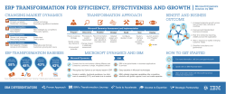


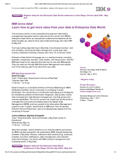
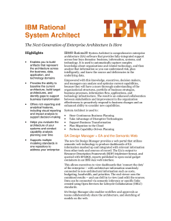


© Copyright 2026