
Safe.t Solutions
Safe.t® Solutions Safe.t® Components Safe.t® Systems Safe.t® Technology Safe.t® Seminars Safe.t® Solutions Safe.t® Components Safe.t® Systems Safe.t® Technology Safe.t® Seminars Safe.t® Solutions Safe.t® Components Safe.t® Systems Safe.t® Technology Safe.t® Seminars Safe.t® Solutions Safe.t® Components Safe.t® Systems Safe.t® Technology Safe.t® Seminars Safe.t® Solutions Safe.t® Components Safe.t® Technology Safe.t® Seminars Safe.t® Solutions Safe.t® Components Safe.t® Solutions Safe.t® Systems Safe.t® Components Safe.t® Systems Safe.t® Technology Safe.t® Seminars Safe.t® Technology Safe.t® Solutions Safe.t® Components BARTEC GmbH Germany Max-Eyth-Straße 16 97980 Bad Mergentheim Phone:+49 7931 597-0 Fax: +49 7931 597-119 [email protected] www.bartec-group.com Heating Technology UK-D-BEH041004-10/2014-BARTEC WerbeAgentur-233564 2014 Safe.t® Systems Safe.t® Seminars Heating Technology Reservation Technical data subject to change without notice. No claims for damages arising from alterations, errors or misprints shall be allowed. Attention is drawn to the applicable standards and regulations on safety components and systems together with the relevant operating and installation instructions. BARTEC Catalogue Heating Technology Edition 2014 Printed in Germany Content Your applications − our solutions Summary of heating systems 4-9 10 - 13 Heating tapes/Heating cable systems PSBL Heating tape systems 14 - 25 System overview 14 - 15 Heating tape PSBL, 07-5807-1..., 07-5807-2... 16 - 19 Plug-in connection system PLEXO TCS, 27-59 P.-..10 20 - 21 Junction box Ex, 27-5452-.... 22 Cold-applied technology Ex and M, 05-0091-013. 23 Heat shrink technology Ex, 05-0091-0198 und M, 07-5807-0000/99.0 24 Terminal box/Mini-Thermostat M, 05-0041-0195, 05-0060-008. 25 PSB Heating tape systems 26 - 41 System overview 26 - 27 Heating tape PSB, 07-5801-1..., 07-5801-2... 28 - 31 Plug-in connection system PLEXO TCS, 27-59 P.-..10 32 - 33 Junction box Ex, 27-5452-.. 34 Cold-applied technology Ex and M, 05-0091-01.. 35 Heat shrink technology Ex, 05-0091-0097 and M, 07-5801-0000/9... 36 Connection technology TWISTO-B, M, 27-56K.-.... Junction boxes for TWISTO-B, M, 07-5177-902. 39 Junction boxes for heat shrink and cold-applied technology M, 07-5177-902. 40 37 - 38 MSB Heating tape systems 42 - 51 System overview 42 - 43 Heating tape MSB, 07-5804-2..Y 44 - 47 Plug-in connection system PLEXO TCS, 27-59 P.-..10 48 - 49 Junction box Ex, 27-5452-.... 50 Cold-applied technology Ex, 05-0091-01.. 51 HSB Heating tape systems 52 - 67 System overview 52 - 53 Heating tape HSB, 07-5803-1..A, 07-5803-2..A 54 - 57 Plug-in connection system PLEXO TCS, 27-59 P.-..10 58 - 59 Junction box Ex, 27-5452-.... 60 Cold-applied technology Ex, 05-0091-01.. 61 Heat shrink technology Ex, 05-00..-00.. und M, 07-5803-000/98.0 62 Connection system CONPAC, 27-563G-SF7.. Junction boxes for CONPAC, M, 07-5177-902. 65 Junction boxes for heat shrink and cold-applied technology M, 07-5177-902. 66 63 - 64 HTSB Heating tape systems 68 - 75 System overview 68 - 69 Heating tape HTSB, 07-5809-2..N 70 - 72 Cold-applied technology Ex, 05-0091-0..., 03-6020-0168 73 Junction boxes for cold-applied technology Ex, 07-5103-921. 74 EKL Heating cable system 76 - 93 76 - 77 System overview EKL light Heating cable, 27-582.-5A6A.... Heat Shrink Technology M, 05-0091-0195 Junction box M, 07-5177-9... EKL medium Heating cable, 27-582.-756G.... Plug-in connection system PLEXO Ex, 27-59SE-H01710.. Junction box Ex, 07-5103-9... EKL premium Heating cable, 27-582.-756K.... Plug-in connection system PLEXO Ex, 27-59SE-HO1710.. Junction box Ex, 07-5103-9... EMK Heating cable system Single-core mineral-insulated heating cable, 27-3833-20..; 27-3834-20.. Connection kits, Ex and M Heating circuits, pre-assembled, M 27-3623-.... and Ex 27-3621-.... Single-core mineral-insulated heating cable, laser welded, pre-assembled, Ex and M 27-364.-.31/....1000 78 - 79 80 81 - 82 83 84 85 - 87 88 89 90 - 92 94 - 109 94 - 95 96 97 - 101 102 - 108 SEH Skin Effect Heating system 110 - 111 110 - 111 System overview Installation accessories for PSBL/PSB/MSB/HSB/HTSB/EKL/EMK Insulation entry bush 05-0020-0... Adhesive tapes 02-5500-00.. Over insulation caution labels 05-2144-0... Connection cables 02-4034-00.. Crimping accessories 03-....-000. Mounting plates and brackets in stainless steel 05-0091-00.. Mounting plates and brackets in galvanised steel 05-0..5-0... S/S cable ties 03-.510-0... Nylon cable ties 03-6500-001. Fixing straps 02-/03-... 112 - 115 Closed- and open-loop control system 116 - 171 116 - 117 Summary of closed- and open-loop control systems Capillary tube thermostat STW II, 16 A, fail-safe 27-6DF2-5215/1.00 118 - 119 120 - 123 Safety temperature monitor BSTW II and -limiter BTB II/BSTB II, 25 A, fail-safe, 27-6D..-52../1..0 Flame-proof temperature monitor/limiter DTW/DTB 27-6C.2-.4112000 124 - 125 126 - 127 Mini-thermostat MTE, 07-6111-94.. Cable thermostat KTE-m, 27-6B11-2.10/BZ.. 128 Cable thermostat KTE-d, 27-6B11-52../BZ.. 129 Capillary tube thermostat KRM, 16 A, 27-6A.3-61... 130 - 131 Complete Digital Solution DEPU - Controller-Limiter-Power Setpoint 17-8887-2636/2300 132 - 133 DPCfront Digital programmable Temperature control device family 134 - 137 DPCfront Standard, 17-8821-7720/32204000 135 DPCfront Komfort, 17-8821-7780/34204000 136 DPCfront Monitor, 17-8821-7783/34204200 137 DPC III Digital programmable family Digital Temperature control device DPC III Standard, 17-8821-4.22/22303000 Digital Temperature control device DPC III Monitor, 17-8821-4.22/22303200 Digital Safety Temperature Limiter DTL III Ex, 17-8865-4.22/22003000 CodeKey DPC III and DPCfront, 17-82L3-1110 138 - 142 MPCnet Multi-Channel Control System System overview Gateway GW32, 17-8851-0002 Controller Module MC32, 17-8851-0001 Remote I/O-Modules for Temperature Measurement 8TI and 16 TI, 17-8851-001. Remote I/O-Modules for Load Switching 8DO and 16 DO, 17-8851-001. Remote I/O-Modules for Function Monitoring 8DI and 16DI, 17-8851-001. Remote I/O-Modules for Current Measurement 8CI and 16CI, 17-8851-002. Communication Modules TM04 and TS04, 17-8851-000. Power Modules TR16 and TR36, 17-8851-001. Temperature Limiter TL Ex, 17-8851-0030/0000 143 - 161 143 - 144 145 146 - 147 154 - 155 156 - 157 158 - 159 160 - 161 MPC II Multi-Channel Control System System overview MPC II Standard, for 8 heating circuits, 17-8841-13.0/0200 MPC II Comfort, for 16 heating circuits, 17-8841-23.1/0400 MPC II Professional, for 24 heating circuits, 17-8845-33.4/1400 Digital energy controller DEC, 17-82L3-1110 Resistance thermometer Pt100 Ex, 27-712.-1330.... Junction boxes for Pt100 Ex, 07-510./90.. Resistance thermometer Pt100 M, 03-9040-00.. Junction boxes for Pt100 M, 07-5177-908. 162 - 171 162 163 164 165 166 - 167 168 169 170 171 Heaters Mini-heater, Ex 27-2301-3806 and M 27-2302-3806 Radiator HCS, 27-2063-3704/B300 Radiator HCM, 27-216.-57../B300 Radiator HCL, 27-226.-47.0/B3.. Radiator HSF, 27-2.5.-7..41.. Silicone heater plate for control cabinets SSM, 27-02.2-.7.. Anti-condensation motor heater MSH, 27-1811-... Anti-condensation motor heater MSHex, 27-1776-... 172 - 183 172 - 173 174 175 176 - 177 178 - 179 180 - 181 182 183 Water leakage detection systems System overview Sensor cabel SCR, 17-85M1-1761 Point sensor PS, 17-85M1-3832/0A00 Monitoring electronics RLW with locating, 17-85G1-2... Monitoring electronics RDW 03 without locating, 17-85F3-8322 Monitoring electronics RDA 01 without locating, 17-85F4-2.22 185 - 190 186 187 187 188 189 190 Project planning information for electric trace heating systems for pipes for electric trace heating system for tanks and vessels 139 140 141 142 148 - 149 150 - 151 152 - 153 191 192 BARTEC Heating Technology Your applications... Frost protection Temperature maintenance Heating Safe product and plant protection against frost damages Reliable adherence to in-process, down-time and storage temperatures for liquid and gas media Calculated heating of material and liquid media for the accurately timed attainment of the required in-process and storage temperatures Pipe trace heating Heating of simple as well as complex pipe systems, from short to very long including the heating of all components such as flanges, valves, pumps and other equipment. Container heating Heating of all kinds of containers such as tanks, silos and others for the reliable and safe temperature 03-0330-0234/D-10/2013-BEH-201981/1 maintenance of the media stored within. 4 BARTEC Heating Technology Heating of bins and silos Heating of hoppers and conveyors, e. g. in power plants and pollution control plants. Heating of analyzer systems Precision heating of pulse and measurement performances from tapping to analyser system. Heating of cabinets and instrumentations Heating of transmitter cases, control boxes and cabinets as well as customer-tailored heating of instrumentation and process control equipment such as pressure gauges, flow-rate meters, liquid 03-0330-0234/D-10/2013-BEH-201981/2 level indicators. 5 BARTEC Heating Technology Our solutions Heating tapes/Heating cables PSBL/PSB/MSB/HSB/HTSB Self-limiting heating tapes EKL Plastic single-core heating cables EMK Mineral-insulated heating cables SEH Skin Effect heating cables Connection systems PLEXO TCS plug-in connection system for industrial applications and for hazardous areas CONPAC connection system for industrial applications for HSB TWISTO-B connection system for industrial applications in non-explosive atmospheres for PSB Heat shrink technology the connection system for industrial applications and for hazardous areas 03-0330-0234/D-09/2014-BEH-201981/3 Silicone cold-applied technology Installation without hot work permit for industrial applications and for hazardous areas 6 BARTEC Heating Technology Control systems and temperature sensors Electromechanical capillary tube controllers and temperature limiters as well as an extensive range of electronic closed and open loop devices and power controllers for the use in hazardous areas and industrial applications Ambient thermostats, two-position controllers, proportional controllers and PID controllers Single, bus-capable for up to 256 heating circuits Pt100 temperature sensor for the direct use in explosive atmospheres and for industrial applications Multi-channel control systems with bus capability for up to 2000 heating circuits Heaters Self-limiting and constantly heating heating plates for use in hazardous areas Heater plates for control cabinets Mini-heaters Anti-condensation motor heaters Installation accessoires Junction box Mounting material Mounting plates and brackets 03-0330-0234/D-09/2014-BEH-201981/4 Insulation entries Over insulation caution labels 7 BARTEC Heating Technology Our support Project planning software Heloc This software product was developed to help the user project the complete layout of all electric trace heating systems for pipes and vessels in no time at all. Our project planning software is extremely userfriendly and easy to handle. It proposes Heat loss calculations Heating circuit layouts Different heating cables Material list Budgeting Print out of each single heating circuit Download free of charge from: www.bartec-group.com Technical support As a supplier of complete systems we know from experience how important it is to have project planning engineers and product advisors standing by ready for action. Seminars and training At regular intervals we offer technical seminars at our parent company in Bad Mergentheim. We also offer in-house training for your technical staff. Product application seminars Project planning workshops 03-0330-0234/D-10/2013-BEH-201981/5 Installation training 8 BARTEC Heating Technology Ideal trace heating solutions for all applications Economic solution You can choose many different heating systems. This allows you to find your ideal solution also with regard to economic aspects. For not every system is suitable for every application. It is the choice of the correct system which guarantees the satisfaction of all your individual requirements. Safe and reliable products BARTEC’s all-time objective is the safety for people, environment, plant and machinery. Our products and solutions provide the highest safety standards and have been tried and tested in many applications all over the world. From heating components to engineering Experienced engineers do the entire basic and detailed engineering for you. They analyse the task to be accomplished, taking account of local laws and regulations. They conduct feasibility studies and work out a rough strategy. Quantities/capacities and costs are planned with due consideration to criteria of economic efficiency. BARTEC then uses the basic engineering to draw up detailed engineering containing a more precise strategy 03-0330-0234/D-10/2013-BEH-201981/6 for producing the system. The required measures are discussed and agreed on with the customer directly. 9 BARTEC Heating Technology Summary of heating systems Heating tape PSBL Heating systems Heating tape MSB Heating tape PSB Heating tape HSB Heating tape HTSB System PSBL System PSB System MSB System HSB System HTSB Self-limiting parallel heating tapes PSBL Self-limiting parallel heating tapes PSB Self-limiting parallel heating tapes MSB Self-limiting parallel heating tapes HSB Self-limiting parallel heating tapes HTSB yes yes yes yes yes Heating power 1) 10 to 30 W/m 10 to 33 W/m 10 to 40 W/m 10 to 60 W/m 15 to 90 W/m Max. operating temperature 2) heating tape energized (switched on) +65 °C +65 °C +110 °C +120 °C +200 °C Resistant to steam cleaning - - - yes yes Max. length of heating circuit 3) per power feeding point 154 m 205 m 235 m 235 m 154 m Max. operating voltage 120 V/254 V 120 V/254 V 254 V 120 V/254 V 254 V Suitable for corrosive atmospheres 4) yes yes yes yes yes Explosion protection Technical data 1) Different nominal powers available Reference value: each case will depend on conductor/surface temperature of the heating cable and the application itself 2) 3) Reference value: depending on application, depend on ambient temperature 4) To be tested for individual cases 03-0330-0235/F-09/2014-BEH-201982/1 * Multiple occupancy 10 BARTEC Heating Technology Summary of heating systems Heating cable EKL Heating systems Heating cable EMK CuNi Heating cable EMK VA Heat tube SEH System EKL System EMK CuNi System EMK VA System SEH Single-core plastic insulated heating cables EKL Mineral-insulated heating cables EMK, Outer jacket CuNi Mineral-insulated heating cables EMK, Outer jacket VA or Incoloy Heat tube SEH yes yes yes yes Heating power approx. 25/30 W/m 150 W/m 250 W/m ~ 200 W/m* Max. operating temperature 2) +260 °C +500 °C +1000 °C +260 °C Resistant to steam cleaning yes yes yes yes Max. length of heating circuit 3) per power feeding point 3000 m 1000 m 1000 m > 20 km Max. operating voltage 500 V/750 V 500 V/750 V 500 V/750 V 5000 V Suitable for corrosive atmospheres 4) yes yes yes no Explosion protection Technical data 1) Different nominal powers available Reference value: each case will depend on conductor/surface temperature of the heating cable and the application itself 2) 3) Reference value: depending on application, depend on ambient temperature 4) To be tested for individual cases 03-0330-0235/F-09/2014-BEH-201982/2 * Multiple occupancy 11 BARTEC Heating Technology Heating System Components Heating System Components - typical application PSBL PSB M Connection MSB M PLEXO TCS Connection system TWISTO-B Connection system CONPAC HSB Connection system Heat shrink technology Connection technology Cold-applied technology Connection technology PLEXO EKL medium/EKL premium Connection set EMK “Ex“ Connection set EMK “Standard“ Connection set HSB M M Control units STW II Safety temperature monitor BSTW II Safety temperature monitor BTB II/BSTB II Safety temperature limiter DTW/DTB Flame-proof resistant temperature controller/limiter MTE Mini thermostat KTE Cable thermostat KRM Capillary tube thermostat DEPU Complete digital solution DPC III Digital temperature controller 1 1 1 1 1 DPCfront Digital temperature controller (front panel) 1 1 1 DTL III Ex Digital temperature limiter DEC Digital power controller MPC II/MPCnet Multiplex controller 1 1 1 Pt100 Ex Resistance thermometer Pt100 M Resistance thermometer 1 1 03-0330-0235/E-09/2014-BEH-201982/3 Mounting accessories Junction boxes for heating circuit Junction box Pt100 Insulation entries Adhesive aluminium tapes Adhesive textile tapes Adhesive polyester tapes Adhesive glass fibre tapes Caution Labels Mounting plates and fixing brackets (S/S) Mounting plates and fixing brackets (galv. steel) Fixing strap and buckle for mounting rail Polyester fixing strap and buckle EKL spacing strips EMK spacing strips Wire mats, welding rods, spring lock washers Stainless steel cable ties Nylon cable ties = Used outside the Ex area but acts on explosion-protected heating circuits in the Ex area. 1 12 BARTEC Heating Technology Heating System Components Heating System Components - typical application HTSB EKL M Connection PLEXO TCS Connection system TWISTO-B Connection system CONPAC HSB Connection system Heat shrink technology Connection technology Cold-applied technology Connection technology PLEXO EKL medium/EKL premium Connection set EMK “Ex“ Connection set EMK “Standard“ Connection set EMK M SEH M M Control units STW II Safety temperature monitor BSTW II Safety temperature monitor BTB II/BSTB II Safety temperature limiter DTW/DTB Flame-proof resistant temperature controller/limiter MTE Mini thermostat KTE Cable thermostat KRM Capillary tube thermostat DEPU Complete digital solution DPC III Digital temperature controller DPCfront Digital temperature controller (front panel) DTL III Ex 1 1 1 1 1 1 Digital temperature limiter 1 1 DEC Digital power controller 1 1 MPC II/MPCnet Multiplex controller 1 1 1 Pt100 Ex Resistance thermometer Pt100 M Resistance thermometer Mounting accessories Junction boxes for heating circuit Junction box Pt100 Insulation entries Adhesive aluminium tapes Adhesive glass fibre tapes Caution Labels Mounting plates and fixing brackets (S/S) Mounting plates and fixing brackets (galv. steel) Fixing strap and buckle for mounting rail Polyester fixing strap and buckle Adhesive textile tapes 03-0330-0235/E-09/2014-BEH-201982/4 Adhesive polyester tapes EKL spacing strips EMK spacing strips Wire mats, welding rods, spring lock washers Stainless steel cable ties Nylon cable ties = Used outside the Ex area but acts on explosion-protected heating circuits in the Ex area. 1 13 M PSBL system System overview Heating tape PSBL Terminal box Installation kit System overview PSBL Features Description Self-limiting, without overheating while overlapping Typical applications are frost protection, temperature maintenance and heat-up in pipes, tanks, vessels or surfaces. The electric heating system PSBL is the perfect solution in Zone 1, 2, 21 and 22. Limiter is not required Easy installation due to on-site assembly Installation in commercial, industrial and Ex-area, maximum admissible work-piece temperature of +65 °C (switched on). Certificate for the system according to IEC/EN 60079-30-1 Junction boxes made of polyester, stainless steel and aluminium available Calculation and design-software - Free Download 03-0330-0470/E-09/2014-BEH-246902/1 Direct entry in a junction box possible 14 The self-limiting heating tape PSBL is available with various nominal power ratings from 10 W/m to 30 W/m at 10 °C. The standard outer insulation jacket is made of polyolefin. For special applications which require chemical resistance and mechanical strength a fluoropolymer insulation jacket is optionally available. M PSBL system System overview System overview Explosion protection Self- limiting parallel heating tape PSBL Certification KEMA 08 ATEX 0112 X IECEx KEM 09.0085X TC RU C-DE.ГБ06.B.00230 Heat shrink technology or silicone cold applied technology or pluggable system PLEXO TCS connection and termination Junction box made of polyester, stainless steel and aluminium Optional: mechanical or electronic thermostats or control systems Application example PSBL heating system 1 2 3 4 5 5 Heating tape PSBL 2 Mounting bracket 6 Caution label ”Electrically Heated” 3 Connection cable for power supply 7 End termination PLEXO TCS 4 Connection PLEXO TCS 7 03-0330-0470/E-09/2014-BEH-246902/2 1 Junction box 6 15 M PSBL system Heating tape PSBL Features Self-limiting Can be used in explosive athmospheres without temperature limiter Can be cut to any length due to the parallel current supply Resistant to corrosion and chemical influences because of the external protective jacket Tinned copper braiding for electrical Self-limiting parallel heating tape PSBL 1.Conductors: stranded copper wire 1.0 mm2, tinned 2. Self-limiting, irradiated polymer heating element 3. Polyolefin electrical insulation jacket and mechanical protection Easy installation due to high level of flexibility Description Around two parallel positioned copper wires with a cross-section of 1 mm² an irradiated electrically conducting polymer is extruded. This electrically conducting matrix responds to changes of the ambient temperature with an increase or decrease of the heating output. A flame-retardant, UV-resistant jacket protects the braiding against humidity and offers additional protection against mechanical stress. The heating system must be designed to ensure that the maximum operating temperature of 65 °C will not be exceeded when it is energized. When it is switched off, the heating tape can be exposed to a temperature of 85 °C, not more than 1,000 hours cumulated. 4. Tinned copper braiding 03-0330-0471/E-09/2014-BEH-246903/1 5. Polyolefin or alternatively fluoropolymer protective jacket 16 M PSBL system Heating tape PSBL PSBL characteristics 40 The PSBL heating tape is suitable for electric trace heating for frost protection of pipelines and vessels. Power output W/m 35 Areas of application PSBL 30 While the polyolefin protective jacket is used where there are aqueous, inorganic chemicals, the fluoropolymer outer jacket is suitable for organic chemicals. For questions regarding the chemical resistance please contact your BARTEC sales representative. Explosion protection 30 PSBL 25 25 PSBL 20 20 PSBL 15 Ex protection type II 2G Ex e IIC T5 Gb II 2D Ex tb IIIC T95 °C Db Certification System KEMA 08 ATEX 0112 X IECEx KEM 09.0085X TC RU C-DE.ГБ06.B.00230 Heating tape KEMA 02 ATEX 2326 U IECEx KEM 07.0047 U 15 PSBL 10 10 5 0 0 5 101520253035404550556065 Pipe temperature °C 03-0330-0471/E-09/2014-BEH-246903/2 Power output on insulated steel pipes at 230 V under nominal conditions. 17 M PSBL system Heating tape PSBL Technical data Nominal voltage AC 208 V to 254 V AC 110 V to 120 V Power setting at +10 °C Power output PSBL 10 PSBL 15 PSBL 20 PSBL 25 PSBL 30 at AC 230 V 10 W/m 15 W/m 20 W/m 25 W/m 30 W/m at AC 120 V 10.6 W/m 15.7 W/m 20.8 W/m 25.8 W/m 30.6 W/m Max. exposure temperature switched on switched off +65 °C +85 °C Min. installation temperature -55 °C Min. start-up temperature -30 °C +85 Max. braid resistance <18,2 Ω/km +65 Dimensions with braiding and jacket 10,5 x 6,0 mm Min. bending radius 25 mm Maximum exposure temperature °C +100 n m x +50 0 T Continuous operation, switched on heating tape Period of time in switched-off state , n + m + x ... ≤ 1000 h (n, m, x... ≤ 48 hours, breaks in between at least 4 weeks) Max. length of heating circuit at AC 230 V for automatic circuit-breakers with C characteristic Circuit breaker size PSBL 10 PSBL 15 10 A, start-up temperature +10 °C 118 m 104 m 10 A, start-up temperature -15 °C 90 m 10 A, start-up temperature -30 °C PSBL 20 PSBL 25 PSBL 30 79 m 60 m 45 m 69 m 49 m 39 m 24 m 77 m 56 m 40 m 30 m 16 m 16 A, start-up temperature +10 °C 154 m 139 m 110 m 83 m - 16 A, start-up temperature -15 °C 136 m 89 m 71 m 56 m - 16 A, start-up temperature -30 °C 118 m 78 m 58 m 47 m - 03-0330-0471/C-09/2014-BEH-246903/3 Max. length of heating circuit at AC 120 V for automatic circuit-breakers with C characteristic 18 Circuit breaker size PSBL 10 PSBL 15 PSBL 20 PSBL 25 PSBL 30 10 A, start-up temperature +10 °C 49 m 43 m 33 m 25 m - 10 A, start-up temperature -15 °C 45 m 35 m 25 m 20 m - 10 A, start-up temperature -30 °C 39 m 28 m 20 m 15 m - 16 A, start-up temperature +10 °C 77 m 58 m 46 m 35 m - 16 A, start-up temperature -15 °C 68 m 45 m 36 m 28 m - 16 A, start-up temperature -30 °C 59 m 39 m 29 m 24 m - M PSBL system Heating tape PSBL Selection chart PSBL Description Protective jacket Type Order no. PSBL parallel heating tape AC 254 V fluoropolymer PSBL 10 07-5807-2105 PSBL 15 07-5807-2155 PSBL 20 07-5807-2205 PSBL 25 07-5807-2255 PSBL 30 07-5807-2305 PSBL 10 07-5807-2106 PSBL 15 07-5807-2156 PSBL 20 07-5807-2206 PSBL 25 07-5807-2256 PSBL 30 07-5807-2306 PSBL 10 07-5807-1105 PSBL 15 07-5807-1155 PSBL 20 07-5807-1205 PSBL 25 07-5807-1255 PSBL 10 07-5807-1106 PSBL 15 07-5807-1156 PSBL 20 07-5807-1206 PSBL 25 07-5807-1256 PSBL 10 07-5807-2108 PSBL 15 07-5807-2158 PSBL 20 07-5807-2208 - tinned copper braiding PSBL 25 07-5807-2258 - Ex marked PSBL 30 07-5807-2308 PSBL 10 07-5807-2109 PSBL 15 07-5807-2159 PSBL 20 07-5807-2209 PSBL 25 07-5807-2259 PSBL 30 07-5807-2309 PSBL 10 07-5807-1108 PSBL 15 07-5807-1158 PSBL 20 07-5807-1208 PSBL 25 07-5807-1258 PSBL 10 07-5807-1109 PSBL 15 07-5807-1159 PSBL 20 07-5807-1209 PSBL 25 07-5807-1259 - self-limiting - media protected - tinned copper braiding polyolefin PSBL parallel heating tape AC 120 V fluoropolymer - self-limiting - media protected - tinned copper braiding polyolefin PSBL parallel heating tape AC 254 V fluoropolymer - self-limiting - explosion protected polyolefin PSBL parallel heating cable AC 120 V fluoropolymer 03-0330-0471/C-09/2014-BEH-246903/4 - self-limiting - explosion protected - tinned copper braiding - Ex marked polyolefin 19 PSBL system PLEXO TCS – the plug-in connection system Connection system PLEXO TCS Features Description Cross-section of connection cable The PLEXO TCS connection system can be used for BARTEC self-limiting heating tapes. This modular connection technology allows an easy and reliable assembly of supply connections, splicing and remote-end terminations. PLEXO TCS is plugged and built up with a patented sealing and clamping technology. up to 4 mm2 Operating temperature range from -60 °C to +180 °C Integrated strain relief; high electrical and mechanical safety Quick and easy installation, with standard tools System approval with BARTEC The strands from the heating tape or the supply cable are fixed in place securely by spring-loaded terminals in the internal clamping technology. self-limiting heating tapes Dimensions (in mm) Dimensions (in mm) Type 27-59P3-00100000 Type 27-59P1-*0100000 and 27-59P2-01100000 03-0330-0720-09/2014-BEH-348954/1 202.7 20 Maintenance work and later modifications on the heating circuit can be done quick and flexible. 67 67 43.4 43.4 118.3 PSBL system PLEXO TCS – the plug-in connection system Explosion protection Technical data Ex protection type PLEXO TCS with heating tape II 2G Ex e IIC T5 Gb II 2D Ex tb IIIC T95 °C Db Rated voltage max. 254 V Rated current max. 16 A Certification PLEXO TCS with heating tape BVS 13 ATEX E 040 X IECEx BVS 13.0048X TC RU C-DE.ГБ06.B.00230 Protection class EN 60079-0 IP 65 EN 60529 IP 66/IP 68 Operating temperature range Ex application: -60 °C to +180 °C Non Ex application: -60 °C to +200 °C PSBL-System KEMA 08 ATEX 0112 X IECEx KEM 09.0085X TC RU C-DE.ГБ06.B.00230 Rated cross-section of supply cable max. 4 mm2 Minimum installation temperature -55 °C Sealing range supply cable see type selection Selection chart PLEXO TCS Description Order no. PLEXO heating tape connection to supply cable with sealing range 8 < DA ≤ 10 mm 27-59P1-1010 10 < DA ≤ 12 mm 27-59P1-2010 12 < DA ≤ 14 mm 27-59P1-3010 14 < DA ≤ 16 mm 27-59P1-4010 PLEXO heating tape splice with sealing range for PSBL 27-59P2-0110 PLEXO heating tape remote-end termination with sealing range for PSBL 27-59P3-0010 Selection chart Accessories Description Order no. Connection cable 03-0330-0720-09/2014-BEH-348954/2 Heat-resistant connection cable with silicone outer sheath (H05SS-F quality, EWKF outer sheath, -50 °C to +180 °C) Cross-section 3 x 1.5 mm2 DA = 8.5 mm 02-4034-0008 Cross-section 3 x 2.5 mm2 DA = 9.8 mm 02-4034-0027 Mounting bracket 05-0105-0385 The PLEXO TCS can be mounted with the optional mounting bracket outside the thermal insulation. Technical data subject to change without notice. 21 PSBL system Junction box Junction box for PLEXO TCS, heat shrink and cold-applied technology Features Explosion protection Wide temperature range Ex protection type System II 2G Ex e IIC T5 Gb II 2D Ex tb IIIC T 95 °C Db Can be combined with connection technology PLEXO, heat shrink and cold-applied technology Certification System KEMA 08 ATEX 0112 X IECEx KEM 09.0085X TC RU C-DE.ГБ06.B.00230 Flame-retardant Impact-resistant System approval Description Inside the junction box up to three heating circuits can be connected to the supply voltage. One cable gland with size M25 for the power cable is already assembled at the junction box. The enclosure is prepared with threads for heating tape glands with size M20. Technical data Protection class according to EN 60529 seal of cover IP 65 cable gland IP 65 Ambient temperature -55 °C up to + 55 °C Dimensions see selection chart Material Polyester, glass fibre reinforce Dimensions (polyester, aluminium) Voltage AC 254 V 122 106 Circuit protection Max. 16 A (dependant on the heating circuit length) 82 120 82 120 ∅ 6.5 ∅ 6.5 220 204 03-0330-0572/D-09/2014-BEH-301445 Selection chart Designation Description Polyester System 27-1580-..10/.... Aluminium System 27-1580-..10/.... Stainless steel System 27-1580-..10/.... 22 Dimensions (mm) Terminals (mm²) Order no. for 1 heating circuit 122 x 120 x 90 4 x 6; 4 x PE 27-5452-42111210 for 2/3 heating circuits 220 x 120 x 90 12 x 6; 8 x PE 27-5452-44311210 for 1 heating circuit 122 x 120 x 90 4 x 6; 4 x PE 27-5452-52111230 for 2/3 heating circuits 220 x 120 x 90 12 x 6; 8 x PE 27-5452-54311230 for 1 heating circuit 150 x 150 x 100 4 x 6; 4 x PE 27-5452-67111230 for 2/3 heating circuits 200 x 200 x 120 12 x 6; 8 x PE 27-5452-68311230 M PSBL system Cold-applied technology Cold-applied technology explosion protected media protected Features Description Description Direct entry of a heating tape into the junction box For direct connection of self-limiting heating tape PSBL (Order no. 07-5807-....) into the junction box the 2 supply leads are insulated with silicone glue and a silicone hose. A green yellow protection tube is pulled over the tinned copper braiding inside the insulation sheath. For direct connection of self-limiting heating tape PSBL (Order no. 07-5807-....) into the junction box the 2 supply leads are insulated by silicone glue and a silicone hose. A green-yellow protection tube is pulled over the tinned copper braiding inside the insulation sheath. The copper braiding and the metal cable gland with an extra lead are prepared to be connected to the protective earth. The end of the self-limiting heating tape is insulated with silicone glue and a silicone end cap. The copper braiding is prepared to be connected to the protective earth. The end of the self-limiting heating tape is insulated with silicone glue and a silicone end cap. Connection and termination in one set Space-saving solution Easy design and assembling with silicone cold-applied technology Explosion protection Ex protection type System II 2G Ex e IIC T5 Gb II 2D Ex tb IIIC T95 °C Db Certification System KEMA 08 ATEX 0112 X IECEx KEM 09.0085X TC RU C-DE.ГБ06.B.00230 Technical data Technical data Ambient temperature range -40 °C up to +85 °C Max. operating temperature end cap +85 °C Electrical data see PSBL data 10, 15, 20, 25, 30 W/m Ambient temperature range -55 °C up to +55 °C Max. operating temperature end cap +85 °C Electrical data 03-0330-0571/B-09/2014-BEH-301424 see PSBL data 10, 15, 20, 25, 30 W/m Order no. Installation kit explosion protected set05-0091-0131 10 fold set05-0091-0137 Order no. Installation kit media protected 10 fold set 05-0091-0139 Technical data subject to change without notice. 23 M PSBL system Heat shrink technology Heat shrink technology explosion protected media protected Features Description Description Direct entry of a heating tape into an Ex e junction box Heat shrink technology is a reliable technology to connect heating tapes. Space-saving solution The principle is easy. After the preparation of the heating tape, insulation tubes are shrunk over the conductors and the twisted protective braiding and wire end sleeves are placed. If the heating tape is directly connected to the enclosure terminals, the heating tape is first prepared and then insulation tubes are shrunk over the conductors as well as the twisted protective braiding. Afterwards ferrules are placed. The heating tape is connected directly to terminals in a junction box, IP 65 protection class. Easy installation Basically, the heating tape is connected to terminals in an enclosure that has the protection type “increased safety“. The heating circuit end is also closed with shrinkable tubes. Explosion protection Ex protection type II 2G Ex e IIC T5 Gb II 2D Ex tb IIIC T95 °C Db Certification System KEMA 08 ATEX 0112 X IECEx KEM 09.0085X TC RU C-DE.ГБ06.B.00230 Technical data As an alternative, the heating tape can be connected directly to a connection cable by means of a butt connector. The heating circuit end is closed in each case with a heat shrinkable end cap. Technical data Ambient temperature range -30 °C up to +85 °C Max. operating temperature end cap +85 °C Electrical data see PSBL data 10, 15, 20, 25, 30 W/m Ambient temperature range -30 °C up to +55 °C Max. operating temperature end cap +85 °C Electrical data see PSBL data 10, 15, 20, 25, 30 W/m Order no. Installation kit, explosion protected 05-0091-0198 03-0330-0810-09/2014-BEH-369340 Grounding strap with lock nut, required if metal glands are used in polyester junction boxes 05-0012-0082 Order no. Installation kit, media protected Connection and termination (direct enclosure entry) 07-5807-0000/9910 Connection and termination (flexible with crimp connector) 07-5807-0000/9920 Connection heating tape - heating tape (with crimp connector) 07-5807-0000/9930 Heat resistant connection cable (GY H05GG-F, 3G, 2.5, 3 x 1.5 mm²) 02-4034-0009 Technical data subject to change without notice. 24 M PSBL system Terminal box/Mini-thermostat Terminal box Description The terminal box is suitable for indoor as well as for protected outdoor installations. Technical data Dimensions 88 mm x 88 mm x 53 mm (without external mounting parts) Protection class IP 65/EN 60529 Terminal box 95 88 Ambient temperature range -25 °C up to +40 °C Enclosure material thermoplastic 88 Cable gland 1 x M20 Terminal blocks 7 x AKZ 2.5 mm2 Rated insulation voltage AC 250 V Order no. 05-0041-0195 Mini-thermostat Description This mini-thermostat is used both for monitoring the temperature outside the heating systems and also for regulating the temperature inside transmitter protection boxes or switch and control cabinets. Technical data Electrical data Protection class IP 66/EN 60529 Switching capacity AC 230 V/6 A Connection strands 2 x H07G-K 1.5 mm 0.5 m long Contact element N/C contact (opens when temperature increases) Enclosure material Polyamide Tolerance for switching points 14 °C± 5 K 4 °C ± 3 K 25 °C± 3.5 K 15 °C± 3.5 K Max. temperature at the site of utilisation +70 °C Minimum storage temperature -20 °C It can also be used for monitoring (indicating) temperatures that are too high or too low and it can serve as an alarm contact. Selection chart 03-0330-0472/D-09/2014-BEH-246904 Temperature switching points Code no. +4 °C to +14 °C 7 +15 °C to +25 °C 8 Complete order no. 05-0060-008 Please enter correct code. Technical data subject to change without notice. 25 PSB system System overview PSB Heating tape PSB Junction box Installation kit System overview PSB Features Description Simple project planning of heating circuits Typical applications are frost protection, temperature maintenance and heat-up in pipes, tanks, vessels or surfaces in non-ex areas and in explosive atmospheres for process industry. The electric trace heating system PSB is the perfect solution in Zone 1, 2, 21 and 22 as well as Class I, II and III Div 2. Self-limiting, without overheating while overlapping Limiter is not required Easy installation due to on-site assembly Installation in commercial, industrial and Ex-area Certificate for the system according to IEC/EN 60079-30-1 Junction boxes made of polyester, stainless steel and aluminium available Calculation and design-software - Free Download 03-0330-0473/E-09/2014-BEH-246950/1 Direct entry in a junction box possible 26 The self-limiting heating tape PSB is available with various nominal power ratings from 10 W/m to 33 W/m. The standard outer insulation jacket is made of polyolefin. For special applications which require chemical resistance and mechanical strength a fluoropolymer insulation-jacket is optionally available. Dependant on the start-up temperature respectively the start-up current and the supplied voltages a maximum heating circuit length of 200 m is possible. PSB system System overview PSB System overview Explosion protection Self-limiting parallel heating tape PSB Certification KEMA 08 ATEX 0111 X IECEx KEM 09.0084X TC RU C-DE.ГБ06.B.00230 CSA 1862457 Heat shrink technology or silicone cold applied technology or pluggable system PLEXO TCS connection and termination Junction box made of polyester, stainless steel and aluminium Optional: mechanical or electronic thermostats or control systems Application example PSB heating system 1 2 3 4 5 6 7 8 9 10 5 Buckle for fixing strap 9 Caution label ”Electrically Heated” 2 Mounting bracket/Mounting plate 6 Connection PLEXO TCS 10 End termination PLEXO TCS 3 Connection cable for power supply 7 Self adhesive glass fibre fixing tape 4 Fixing strap 8 Heating tape PSB 03-0330-0473/E-09/2014-BEH-246950/2 1 Junction box 27 PSB system Heating tape PSB Features Self-limiting Can be used in explosive atmospheres without temperature limiter Can be cut at random length thanks to its parallel current supply Corrosion-proof and resistant to effects of chemicals thanks to its outer sheath Electrically and mechanically protected by a Self-limiting parallel heating tape PSB 1.Conductors: stranded copper wire 1.2 mm2, tinned 2. Self-limiting, irradiated polymer heating element 3. Inner polyolefin electrical insulation jacket thermally fused to the heating element (bonded jacket) 4. Outer polyolefin electrical insulation jacket 5. Tinned copper braiding tinned copper braiding Simple installation thanks to its high flexibility and favourable dimensions Description A temperature-dependant resistive element between two parallel copper conductors regulates and limits the heat output of the heating tape according to the ambient temperature. If the ambient temperature rises, the power output of the heating tape is reduced. This self-limiting property prevents overheating even when the tapes are crossed. A temperature limiter is not necessary (also not in hazardous areas). Thanks to the parallel design the heating tape can be cut and installed to any required length. The self-limiting heating tape is available with different power outputs and protective jackets. The protective outer jacket of either fluoropolymer or polyolefin protects the copper braiding from corrosion and chemical impact. Two jackets under the protective braiding provide electrical insulation. The inner one of the two jackets is thermally fused to the heating element (bonded jacket). The heating system must be designed to ensure that the maximum operating temperature of 65 °C will not be exceeded when it is energized. 03-0330-0474/F-09/2014-BEH-246951/1 When it is switched off, the heating tape can be exposed to a temperature of 85 °C, not more than 1,000 hours cumulated. 6. Polyolefin or fluoropolymer protective jacket 28 PSB system Heating tape PSB PSB characteristics Power output W/m 40 Areas of application The PSB heating tape is suitable for electric trace heating for frost protection of pipelines and vessels. PSB 33 35 While the polyolefin protective jacket is used where there are aqueous, inorganic chemicals, the fluoropolymer outer jacket is suitable for organic chemicals. For questions regarding the chemical resistance please contact your BARTEC sales representative. Explosion protection 30 PSB 26 Certification System KEMA 08 ATEX 0111 X IECEx KEM 09.0084X TC RU C-DE.ГБ06.B.00230 CSA 1862457 25 20 PSB 15 15 Ex protection type II 2G Ex e IIC T5, T6 Gb II 2D Ex tb IIIC T95 °C, T 80 °C Db Heating tape KEMA 02 ATEX 2326 U IECEx KEM 07.0047 U PSB 13 PSB 10 25 мм 10 5 0 0 5 101520 2530 35404550 5560 65 Pipe temperature °C 03-0330-0474/F-09/2014-BEH-246951/2 Power output on insulated steel pipes at 230 V under nominal conditions. 29 PSB system Heating tape PSB Technical data Nominal voltage AC 208 V to 254 V, AC 110 V to 120 V Power setting at +10 °C Power output PSB 10 PSB 13 PSB 15 PSB 26 PSB 33 at AC 230 V 10 W/m 13 W/m 15 W/m 25 W/m 33 W/m at AC 120 V 10.6 W/m 13.7 W/m 15.8 W/m 25.8 W/m 33.6 W/m Max. exposure temperature Maximum exposure temperature switched on +65 °C switched off +85 °C °C Min. installation temperature -55 °C Min. start-up temperature -40 °C +85 < 18.2 Ohm/km +65 Max. braid resistance +100 with braiding and Polyolefin jacket x 0 T Continuous operation, switched on heating tape Period of time in switched-off state , n + m + x ... ≤ 1000 h (n, m, x... ≤ 48 hours, breaks in between at least 4 weeks) 11.8 x 5.8 mm Min. bending radius m +50 Dimensions with braiding and Fluoropolymer jacket 11.6 x 5.6 mm n 25 mm Max. length of heating circuit at 254 V (for automatic circuit-breakers with C characteristic) Circuit breaker size PSB 10 PSB 13 PSB 15 PSB 26 PSB 33 16 A, start-up temperature +10 °C 205 m 169 m 145 m 88 m 70 m 16 A, start-up temperature -15 °C 139 m 16 A, start-up temperature -30 °C 120 m 111 m 93 m 58 m 49 m 94 m 77 m 45 m 43 m 20 A, start-up temperature +10 °C 20 A, start-up temperature -15 °C 205 m 179 m 162 m 117 m 90 m 186 m 149 m 125 m 75 m 64 m 20 A, start-up temperature -30 °C 150 m 124 m 106 m 64 m 52 m 25 A, start-up temperature +10 °C 205 m 179 m 162 m 120 m 98 m 25 A, start-up temperature -15 °C 190 m 160 m 142 m 95 m 80 m 25 A, start-up temperature -30 °C 170 m 150 m 135 m 82 m 65 m 32 A, start-up temperature +10 °C 205 m 179 m 162 m 126 m 108 m 32 A, start-up temperature -15 °C 195 m 174 m 160 m 117 m 95 m 32 A, start-up temperature -30 °C 195 m 174 m 160 m 100 m 82 m Max. length of heating circuit at 120 V (for automatic circuit-breakers with C characteristic) 03-0330-0474/D-09/2014-BEH-246951/3 Circuit breaker size 30 PSB 10 PSB 13 PSB 15 PSB 26 PSB 33 16 A, start-up temperature +10 °C 95 m 78 m 67 m 43 m 33 m 16 A, start-up temperature -15 °C 69 m 55 m 45 m 30 m 25 m 16 A, start-up temperature -30 °C 58 m 47 m 39 m 26 m 21 m 20 A, start-up temperature +10 °C 95 m 86 m 80 m 58 m 45 m 20 A, start-up temperature -15 °C 90 m 72 m 60 m 38 m 32 m 20 A, start-up temperature -30 °C 75 m 59 m 49 m 31 m 26 m 25 A, start-up temperature +10 °C 95 m 86 m 80 m 60 m 50 m 25 A, start-up temperature -15 °C 92 m 80 m 70 m 45 m 38 m 25 A, start-up temperature -30 °C 85 m 72 m 65 m 42 m 34 m 32 A, start-up temperature +10 °C 95 m 86 m 80 m 63 m 54 m 32 A, start-up temperature -15 °C 95 m 86 m 80 m 55 m 45 m 32 A, start-up temperature -30 °C 95 m 86 m 80 m 53 m 43 m PSB system Heating tape PSB Selection chart PSB Description Protective jacket Type Order no. PSB parallel heating tape AC 254 V Fluorpolymer PSB 10 07-5801-2105 PSB 13 07-5801-2135 PSB 15 07-5801-2155 PSB 26 07-5801-2265 PSB 33 07-5801-2335 PSB 10 07-5801-2106 PSB 13 07-5801-2136 PSB 15 07-5801-2156 PSB 26 07-5801-2266 PSB 33 07-5801-2336 PSB 10 07-5801-1105 PSB 13 07-5801-1135 PSB 15 07-5801-1155 PSB 26 07-5801-1265 PSB 33 07-5801-1335 PSB 10 07-5801-1106 PSB 13 07-5801-1136 PSB 15 07-5801-1156 PSB 26 07-5801-1266 PSB 33 07-5801-1336 - self-limiting - explosion protected - media protected Polyolefin PSB parallel heating tape AC 120 V Fluorpolymer - self-limiting - explosion protected - media protected Polyolefin 03-0330-0474/D-09/2014-BEH-246951/4 Technical data subject to change without notice. 31 PSB system PLEXO TCS – the plug-in connection system Connection system PLEXO TCS Features Description Cross-section of connection cable The PLEXO TCS connection system can be used for BARTEC self-limiting heating tapes. This modular connection technology allows an easy and reliable assembly of supply connections, splicing and remote-end terminations. PLEXO TCS is plugged and built up with a patented sealing and clamping technology. up to 4 mm2 Operating temperature range from -60 °C to +180 °C Integrated strain relief; high electrical and mechanical safety Quick and easy installation, with standard tools System approved with BARTEC The strands from the heating tapes or the supply cable are fixed in place securely by spring-loaded terminals in the internal clamping technology. self-limiting heating tapes Dimensions (in mm) Dimensions (in mm) Type 27-59P3-00100000 Type 27-59P1-*0100000 and 27-59P2-01100000 03-0330-0720-09/2014-BEH-348954/1 202.7 32 Maintenance work and later modifications on the heating circuit can be done quick and flexible. 67 67 43.4 43.4 118.3 PSB system PLEXO TCS – the plug-in connection system Explosion protection Technical data Ex protection type PLEXO TCS with heating tape II 2G Ex e IIC T5, T6 Gb II 2D Ex tb IIIC T95 °C, T80 °C Db Rated voltage max. 254 V Certification PLEXO TCS with heating tape BVS 13 ATEX E 040 X IECEx BVS 13.0048X TC RU C-DE.ГБ06.B.00230 Rated current max. 32 A Protection class EN 60079-0 IP 65 EN 60529 IP 66/IP 68 Operating temperature range Ex application: -60 °C to +180 °C Non Ex application: -60 °C to +200 °C PSB-System KEMA 08 ATEX 0111 X IECEx KEM 09.0084X TC RU C-DE.ГБ06.B.00230 Rated cross-section of supply cable max. 4 mm2 Minimum installation temperature -55 °C Sealing range supply cable see type selection Selection chart PLEXO TCS Description Order no. PLEXO heating tape connection to supply cable with sealing range 8 < DA ≤ 10 mm 27-59P1-1010 10 < DA ≤ 12 mm 27-59P1-2010 12 < DA ≤ 14 mm 27-59P1-3010 14 < DA ≤ 16 mm 27-59P1-4010 PLEXO heating tape splice with sealing range for PSB 27-59P2-0110 PLEXO heating tape remote-end termination with sealing range for PSB 27-59P3-0010 Selection chart Accessories Description Order no. Connection cable 03-0330-0720-09/2014-BEH-348954/2 Heat-resistant connection cable with silicone outer sheath (H05SS-F quality, EWKF outer sheath, -50 °C to +180 °C) Cross-section 3 x 1.5 mm2 DA = 8.5 mm 02-4034-0008 Cross-section 3 x 2.5 mm2 DA = 9.8 mm 02-4034-0027 Mounting bracket 05-0105-0385 The PLEXO TCS can be mounted with the optional mounting bracket outside the thermal insulation. Technical data subject to change without notice. 33 PSB system Junction box Junction box for PLEXO TCS, heat shrink and cold-applied technology Features Explosion protection Wide temperature range Ex protection type II 2G Ex e IIC T5, T6 Gb II 2D Ex tb IIIC T95 °C, T80 °C Db Can be combined with connection technology PLEXO, heat shrink and cold-applied technology System approval Certification System KEMA 08 ATEX 0111 X IECEx KEM 09.0084X TC RU C-DE.ГБ06.B.00230 CSA 1862457* Description *For further details please contact your BARTEC sales representative. Flame-retardant Impact-resistant Inside the junction box up to three heating circuits can be connected to the supply voltage. One cable gland size M25 for the power cable is already assembled at the junction box. The enclosure is prepared with threads for heating tape glands with size M20. Dimensions (polyester, aluminum) 122 106 Protection class according to EN 60529 seal of cover IP 65 cable gland IP 65 Ambient temperature -55 °C to +55 °C Material Polyester, glass fibre reinforce 82 120 82 120 ∅ 6.5 Technical data Dimensions see selection chart ∅ 6.5 220 204 Voltage AC 254 V Circuit protection max. 32 A (dependant on the heating circuit length) 03-0330-0574/D-09/2014-BEH-301553 Selection chart Designation Description Polyester System 27-1680-..10/.... Aluminium System 27-1680-..10/.... High quality stainless steel System 27-1680-..10/.... 34 Dimensions (mm) Terminals (mm²) Order no. for 1 heating circuit 122 x 120 x 90 4 x 6; 4 x PE 27-5452-42111210 for 2/3 heating circuits 220 x 120 x 90 12 x 6; 8 x PE 27-5452-44311210 for 1 heating circuit 122 x 120 x 90 4 x 6; 4 x PE 27-5452-52111230 for 2/3 heating circuits 220 x 120 x 90 12 x 6; 8 x PE 27-5452-54311230 for 1 heating circuit 150 x 150 x 100 4 x 6; 4 x PE 27-5452-67111230 for 2/3 heating circuits 200 x 200 x 120 12 x 6; 8 x PE 27-5452-68311230 M PSB system Cold-applied technology Cold-applied technology explosion protected media protected Features Description Description Direct entry of a heating tape into the junction box For direct connection of self-limiting heating tape PSB (Order no. 07-5801-...) into the junction box the 2 supply leads are insulated with silicone glue and a silicone hose. A green yellow protection tube is pulled over the tinned copper braiding inside the insulation sheath. For direct connection of self-limiting heating tape PSB (Order no. 07-5801-...) into the junction box the 2 supply leads are insulated by silicone glue and a silicone hose. A green yellow protection tube is pulled over the tinned copper braiding inside the insulation sheath. The copper braiding and the metal cable gland with an extra lead are prepared to be connected to the protective earth. The end of the self-limiting heating tape is insulated with silicone glue and a silicone end cap. The copper braiding is prepared to be connected to the protective earth. The end of the self-limiting heating tape is insulated with silicone glue and a silicone end cap. Connection and termination in one set Space-saving and economic solution Easy design and assembling with silicone cold applied technology Explosion protection Ex protection type II 2G Ex e IIC T5, T6 Gb II 2D Ex tb IIIC T95 °C, T80 °C Db Certification System KEMA 08 ATEX 0111 X IECEx KEM 09.0084X TC RU C-DE.ГБ06.B.00230 CSA 1862457* *For further details please contact your BARTEC sales representative. Technical data Ambient temperature range -40 °C up to +85 °C Max. operating temperature end cap +85 °C Electrical data see PSB data 10, 13, 15, 26, 33 W/m Technical data Ambient temperature range -55 °C up to +55 °C Max. operating temperature end cap +85 °C Electrical data 03-0330-0573/C-09/2014-BEH-301552 see PSB data 10, 13, 15, 26, 33 W/m Order no. Installation kit explosion protected set 05-0091-0130 10-fold set05-0091-0136 Order no. Installation kit media protected 10-fold set 05-0091-0140 Technical data subject to change without notice. 35 M PSB system Heat shrink technology Heat shrink technology explosion protected media protected Features Description Description Direct insertion of a heating tape into an Ex e junction box Heat shrink technology is a reliable technology to connect heating tapes to the power supply. Space-saving solution The principle is easy. After the preparation of the heating tape, insulation tubes are shrunk over the conductors and the twisted protective braiding and ferules are placed. Basically, the heating tape is connected to terminals in an enclosure that has the protection type “increased safety“. The heating circuit end is also closed with shrinkable tubes. If the heating tape is directly connected, to the enclosure terminals, the heating tape is first prepared and then insulation tubes are shrunk over the conductors as well as the twisted protective braiding. Afterwards ferrules are placed. The heating tape is connected directly to terminals in a junction box, IP 65 protection class. Easy Installation Explosion protection Ex protection type II 2G Ex e IIC T5, T6 Gb II 2D Ex tb IIIC T95 °C, T80 °C Db Certification System KEMA 08 ATEX 0111 X IECEx KEM 09.0084X TC RU C-DE.ГБ06.B.00230 Technical data As an alternative, the heating tape can be connected directly to a connection cable by means of a butt connector. The heating circuit end is closed in each case with a heat shrinkable end cap. Technical data Ambient temperature range -20 °C up to +85 °C Max. operating temperature end cap +85 °C Electrical data see PSB data 10, 13, 15, 26, 33 W/m Ambient temperature range -40 °C up to +55 °C Max. operating temperature end cap +85 °C Electrical data see PSB data 10, 13, 15, 26, 33 W/m Order no. Installation kit, explosion protected 05-0091-0097 03-0330-0575/A-09/2014-BEH-301554 Grounding strap with lock nut, required if metal glands are used in polyester junction boxes 05-0012-0082 Order no. Installation kit, media protected Connection and termination (direct enclosure entry) 07-5801-0000/9840 Connection and termination (flexible with crimp connector) 07-5801-0000/9810 Connection heating tape - heating tape (with crimp connector) 07-5801-0000/9560 Technical data subject to change without notice. 36 M PSB system Connection technology TWISTO-B Connection technology TWISTO-B Features Technical data Cost savings because of the reduced assembly time Nominal voltage AC 250 V High reliability of assembly because of few and simple installation steps Nominal current 16 A Description Ambient temperature range -20 °C to +85 °C Simpler and safer to use, yet at the same time faster and thus cheaper, is how the major benefits of the TWISTO-B can be described. This method of connection is for use with BARTEC PSB heating tapes of series 07-5801-2.... All that is needed to assemble a heating circuit is a knife and diagonal cutter. This dispenses with the time-consuming work of exposing the two conductors, the laborious splicing and twisting of the protective braiding and then connecting to a terminal. Just a piece of the outer protective jacket is removed, a clamping sheet is fitted over a part of the exposed braiding, the remaining part is pulled back over the clamping sheet. Protection class IP 66 Dimensions Connection to supply cable/tape connection Diameter 33 x 125 (135) mm End termination 23 x 20 x 37.5 mm Connection with 2 m ready-prepared silicone connector cable (3 x 1.5 mm²) 03-0330-0477/C-09/2014-BEH-246954/1 The heating tape is then inserted into the clamp cutting fixture and by twisting together the two outer sleeves (one sleeve comes ready prepared with a 2 m long supply cable), the heating tape is contacted in the clamp cutting fixture. The end terminal consists of just one part, whereby the end of the heating tape is shortened and inserted into the terminal piece. 37 M PSB system Connection technology TWISTO-B Dimensions (mm) Dimensions (mm) TWISTO B-TE2 TWISTO B-A ∅ 33 124.6 TWISTO B-C 146.3 AF 30 0 200 ∅ 33 . rox app app rox. 300 AF 30 AF 30 TWISTO B-E AF 20 ∅ 22.5 37 Selection chart 03-0330-0477/B-09/2014-BEH-246954/2 Connection technology Technical data subject to change without notice. 38 Description Short form title Order no. Connection to supply cable and end termination as set TWISTO-B-S 27-56KK-DC22 0000 Connection to supply cable TWISTO-B-A 27-56KG-DC22 0000 End termination TWISTO-B-E 27-56KJ-DC00 0000 Heating tape connection TWISTO-B-C 27-56KH-DC00 0000 T-branch for 3 x heating tape 1 I/O TWISTO-B-T 27-56KL-DC00 0000 T-branch with power connection and 2 x heating tape 2 I/O TWISTO-B-TE2 27-56KM-DC22 0000 T-branch with power connection and 3 x heating tape 3 I/O TWISTO-B-TE3 27-56KN-DC22 0000 X-branch for 4 x heating tape 2 I/O TWISTO-B-X 27-56KP-DC00 0000 M PSB System Junction boxes for TWISTO-B Junction boxes for connection system TWISTO-B Description Technical data Up to three heating circuits can be connected to the supply voltage with the polyester junction boxes. Protection class according to EN 60529 Cover gasket IP 65 The enclosures have the appropriate number of terminals and the necessary cable glands resp. the threaded holes. Aluminium junction boxes are available on request. Cable gland IP 67 for power supply cables Supply voltage max. AC 254 V Rated cross-section of supply cable see selection chart Impact resistance 7 Joule Material polyester, glass-fibre reinforced Gland size cable diameter M20 ∅ 6 to 13 mm M25 ∅ 7 to 12/17 mm Selection chart Dimensions mm Cable gland 110 x 75 x 55 1 x M25 (∅ 7 to 17 mm) 1 x M20 4 x 2.5; 4 x PE 07-5177-9021 double 110 x 75 x 55 1 x M25 (∅ 7 to 17 mm) 2 x M20 8 x 2.5; 4 x PE 07-5177-9022 triple 122 x 120 x 90 1 x M25 (∅ 7 to 17 mm) 3 x M20 12 x 6; 6 x PE 07-5177-9023 Junction box triple Junction box double 110 98 122 106 110 98 75 45 ∅ 4.6 ∅ 4.6 75 45 for heating circuit Order no. single Junction box single 03-0330-0478/D-09/2014-BEH-246955/3 for power supply Terminals mm2 ∅ 6.5 TWISTO-B Junction box 120 82 Used for connection system 39 M PSB System Junction boxes for heat shrink and cold-applied technology Junction boxes for heat shrink and cold-applied technology Description Up to three heating circuits can be connected to the supply voltage with the polyester junction boxes. Technical data Protection class according to EN 60529 Cover gasket IP 65 The enclosures have the appropriate number of terminals and the necessary cable glands resp. the threaded holes. Aluminium junction boxes are available on request. Supply voltage max. 254 V Cable gland IP 67 for power supply cables Rated cross-section of supply cable see selection chart Impact resistance 7 Joule Material polyester, glass-fibre reinforced Gland size cable diameter M 20 ∅ 10 to 14 mm Selection chart Junction box Heat shrink or cold-applied technology single Dimensions mm Cable gland Threaded hole for power supply for heating circuit 110 x 75 x 55 1 x M20 (∅ 10 to 14 mm) double 110 x 75 x 55 triple 122 x 120 x 90 Junction box single 1 x M20 4 x 2.5; 4 x PE 07-5177-9024 1 x M20 (∅ 10 to 14 mm) 2 x M20 8 x 2.5; 4 x PE 07-5177-9025 1 x M20 (∅ 10 to 14 mm) 3 x M20 12 x 6; 6 x PE 07-5177-9026 Junction box triple 122 106 110 98 120 82 75 45 ∅ 4.6 ∅ 4.6 75 45 Order no. Junction box double 110 98 03-0330-0478/D-09/2014-BEH-246955/4 Terminals mm2 ∅ 6.5 Used for connection system 40 41 MSB system System overview Heating tape MSB Junction box Installation kit System overview MSB Features Description Simple project planning of heating circuits Typical applications are frost protection, temperature maintenance and heat-up in pipes, tanks, vessels or surfaces in Zone 1,2 and 21, 22. Easy installation due to on-site assembly Installation also in Ex-area, maximum admissible work-piece temperatures of +110 °C (switched-on) and +130 °C (switched-off) Certificate for the system according to IEC/EN 60079-30-1 Junction boxes made of polyester, stainless steel and aluminium available Calculation and design-software - Free Download 03-0330-0742-09/2014-BEH-353454/1 Direct entry in a junction box possible 42 The self-limiting parallel heating tape MSB is available with various nominal power ratings at 10 °C of 10 W/m to 40 W/m. The outer cover is made of thermoplastic elastomer (TPC) default for areas with special requirements to chemical resistance and mechanical strength. Dependant on the start-up temperature respectively the start-up current and the supplied voltages a maximum heating circuit length of 235 m is possible. MSB system System overview System overview Explosion protection Self-limiting parallel heating tape MSB Certification KEMA 08 ATEX 0110 X IECEx KEM 09.0083X TC RU C-DE.ГБ06.B.00230 Silicone cold applied technology or pluggable system PLEXO TCS connection and termination Junction box made of polyester, stainless steel and aluminium Optional: mechanical or electronic thermostats or control systems Application example MSB heating system 1 2 3 4 5 6 7 8 9 10 5 Buckle for fixing strap 9 Caution label ”Electrically Heated” 2 Mounting bracket/Mounting plate 6 PLEXO TCS connection 10 PLEXO TCS end termination 3 Connection cable for power supply 7 Self adhesive glass fibre fixing tape 4 Fixing strap 8 Heating tape MSB 03-0330-0742-09/2014-BEH-353454/2 1 Junction box 43 MSB system Heating tape MSB TPC Features Self-limiting Can be used in temperature class T4 in Ex area Can be cut to length at random thanks to its Self-limiting parallel heating tape MSB TPC 1. Conductors: stranded copper wire, 1.25 mm2, nickel-plated 2. Self-limiting, irradiated polymer heating element 3. TPC electrical insulation jacket parallel current supply Resistant to chemical influences thanks to its protective TPC outer jacket Simple installation thanks to its high flexibility and small dimensions Description A temperature-dependant resistive element between two parallel copper conductors regulates and limits the heat output of the heating tape. This output regulation is carried out automatically along the entire length of the heating tape according to the prevailing ambient temperature. If the ambient temperature rises, the power output of the tape is reduced. Thanks to the parallel design the heating tape can be cut to any required length. This feature considerably simplifies project planning and installation. The heating tape is cut and terminated directly on the construction site according to the circumstances. If the tape will be damaged, it is not necessary to replace the whole tape. BARTEC MSB is available with different power outputs. The heating system must be designed to ensure that the maximum operating temperature of +110 °C will not be exceeded when it is energized. 4. Tinned copper braiding 03-0330-0686-09/2014-BEH-321815/1 5. TPC protective jacket 44 When it is switched off, the heating tape can be exposed to a temperature of 130 °C, not more than 1,000 hours cumulated. MSB characteristics Areas of application Power output W/m MSB system Heating tape MSB TPC The MSB heating tape is suitable for electric trace heating in the industrial area and can be exposed to a temperature of up to 130 °C (switched off). 45 MSB 40 40 With the halogen-free outer jacket, the heating tape is resistant to oil, greases and most chemicals. For questions regarding the chemical resistance please contact your BARTEC sales representative. Explosionsschutz 35 MSB 30 30 MSB 25 25 Ex protection type II 2G Ex e IIC T150 °C (T3), T4 Gb II 2D Ex tb IIIC T150 °C, T130 °C Db Certification System KEMA 08 ATEX 0110 X IECEx KEM 09.0083X Heating tape DEKRA 12 ATEX 0044 U IECEx DEK 12.0004 U 20 MSB 15 15 MSB 10 10 5 0 0 102030405060708090100110 Pipe temperature °C 03-0330-0686-09/2014-BEH-321815/2 Power output on insulated steel pipes at 230 V under nominal conditions. 45 MSB system Heating cable MSB TPC Technical data Nominal voltage AC 208 V up to 254 V Power setting at +10 °C Power output MSB 10 MSB 15 MSB 25 MSB 30 MSB 40 at AC 230 V 10 W/m 15 W/m 25 W/m 30 W/m 40 W/m Permissible ambient temperature for T class Nominal voltage at AC 254 V Heating cable Maximum workpiece temperature T class all +110 °C 150 °C (T3) MSB 10 +100 °C T4 MSB 15 +90 °C T4 MSB 25 +80 °C T4 MSB 30 +70 °C T4 MSB 40 +60 °C T4 Max. exposure temperature switched on +110 °C switched off +130 °C Min. installation temperature -40 °C Maximum exposure temperature °C +150 Min. start-up temperature -50 °C +130 Max. braid resistance < 18.2 Ω/km +110 Dimensions with braiding and TPC jacket 25 mm m x +50 10.2 mm x 4.8 mm Min. bending radius n 0 T Continuous operation, switched on heating tape Period of time in switched-off state , n + m + x ... ≤ 1000 h (n, m, x... ≤ 48 hours, breaks in between at least 4 weeks) 03-0330-0686-09/2014-BEH-321815/3 Max. length of heating circuit at < 254 V (for automatic circuit-breakers with C characteristic) 46 Circuit breaker size MSB 10 MSB 15 MSB 25 MSB 30 MSB 40 16 A, start-up temperature +10 °C 200 m 165 m 120 m 85 m 70 m 16 A, start-up temperature -25 °C 175 m 117 m 88 m 69 m 49 m 16 A, start-up temperature -50 °C 165 m 110 m 80 m 65 m 45 m 20 A, start-up temperature +10 °C 235 m 189 m 140 m 114 m 82 m 20 A, start-up temperature -25 °C 235 m 152 m 120 m 92 m 66 m 20 A, start-up temperature -50 °C 225 m 144 m 114 m 86 m 62 m 32 A, start-up temperature +10 °C 235 m 189 m 140 m 114 m 82 m 32 A, start-up temperature -25 °C 235 m 189 m 140 m 114 m 82 m 32 A, start-up temperature -50 °C 235 m 189 m 136 m 110 m 78 m MSB system Heating cable MSB TPC Selection chart MSB TPC Description Type Heating output MSB parallel heating tape AC 254 V MSB 10 10 W/m 10 MSB 15 15 W/m 15 MSB 25 25 W/m 25 MSB 30 30 W/m 30 MSB 40 40 W/m 40 - self-limiting - explosion protected - media protected Complete order no. 07-5804-2 Code no. Y 03-0330-0686-09/2014-BEH-321815/4 Please enter correct code. Technical data subject to change without notice. 47 MSB system PLEXO TCS – the plug-in connection system Connection system PLEXO TCS Features Description Cross-section of connection cable The PLEXO TCS connection system can be used for BARTEC self-limiting heating tapes. This modular connection technology allows an easy and reliable assembly of supply connections, splicing and remote-end terminations. PLEXO TCS is plugged and built up with a patented sealing and clamping technology. up to 4 mm2 Operating temperature range from -60 °C to +180 °C Integrated strain relief; high electrical and mechanical safety Quick and easy installation, with standard tools System approval with BARTEC The strands from the heating tapes or the supply cable are fixed in place securely by spring-loaded terminals in the internal clamping technology. self-limiting heating tapes Dimensions (in mm) Type 27-59P1-*0100000 and Type 27-59P2-01100000 03-0330-0720-09/2014-BEH-348954/1 202.7 48 Maintenance work and later modifications on the heating circuit can be done quick and flexible. Dimensions (in mm) Type 27-59P3-00100000 67 67 43.4 43.4 118.3 MSB system PLEXO TCS – the plug-in connection system Explosion protection Technical data Ex protection type PLEXO TCS with heating tape II 2G Ex e IIC T150 °C (T3), T4 Gb II 2D Ex tb IIIC T150 °C, T130 °C Db Rated voltage max. 254 V Certification PLEXO TCS with heating tape BVS 13 ATEX E 040 X IECEx BVS 13.0048X TC RU C-DE.ГБ06.B.00230 Rated current max. 32 A Protection class EN 60079-0 IP 65 EN 60529 IP 66/IP 68 Operating temperature range Ex application: -60 °C to +180 °C Non Ex application: -60 °C to +200 °C MSB-System KEMA 08 ATEX 0110 X IECEx KEM 09.0083X TC RU C-DE.ГБ06.B.00230 Rated cross-section of supply cable max. 4 mm2 Minimum installation temperature -40 °C Sealing range supply cable see type selection Selection chart PLEXO TCS Description Order no. PLEXO heating tape connection to supply cable with sealing range 8 < DA ≤ 10 mm 27-59P1-1010 10 < DA ≤ 12 mm 27-59P1-2010 12 < DA ≤ 14 mm 27-59P1-3010 14 < DA ≤ 16 mm 27-59P1-4010 PLEXO heating tape splice with sealing range for MSB 27-59P2-0110 PLEXO heating tape remote-end termination with sealing range for MSB 27-59P3-0010 Selection chart Accessories Description Order no. Connection cable 03-0330-0720-09/2014-BEH-348954/2 Heat-resistant connection cable with silicone outer sheath (H05SS-F quality, EWKF outer sheath, -50 °C to +180 °C) Cross-section 3 x 1.5 mm2 DA = 8.5 mm 02-4034-0008 Cross-section 3 x 2.5 mm2 DA = 9.8 mm 02-4034-0027 Mounting bracket 05-0105-0385 The PLEXO TCS can be mounted with the optional mounting bracket thermal outside the insulation. Technical data subject to change without notice. 49 MSB system Junction box Junction box for PLEXO TCS and cold-applied technology Features Explosion protection Wide temperature range Combined with PLEXO connection system and cold-applied technology Certification System KEMA 08 ATEX 0110 X IECEx KEM 09.0083X TC RU C-DE.ГБ06.B.00230 Flame-retardant Impact-resistant System approval Technical data Description Inside the junction box up to three heating circuits can be connected to the supply voltage. One cable gland size M25 for the power cable is already assembled at the junction box. The enclosure is prepared with threads for heating cable glands with size M20. Dimensions (polyester, aluminum) Ambient condition -55 °C up to + 55 °C Dimensions see selection chart Nominal voltage AC 254 V 82 120 82 120 Protection class according to EN 60529 Seal of cover IP 65 Cable gland IP 65 Material Polyester, glass fibre reinforce 122 106 ∅ 6,5 220 204 Ex protection type II 2G Ex e IIC T150 °C (T3), T4 Gb II 2D Ex tb IIIC T150 °C, T130 °C Db Circuit protection Max. 32 A (dependant on the heating circuit length) 03-0330-0683-09/2014-BEH-321339 Selection chart Designation Description Polyester System 27-1780-..10/.... Aluminium System 27-1780-..10/.... High quality stainless steel System 27-1780-..10/.... Technical data subject to change without notice. 50 Dimensions (mm) Terminals (mm²) Order no. for 1 heating circuit 122 x 120 x 90 4 x 6; 4 x PE 27-5452-42111210 for 2/3 heating circuits 220 x 120 x 90 12 x 6; 8 x PE 27-5452-44311210 for 1 heating circuit 122 x 120 x 90 4 x 6; 4 x PE 27-5452-52111230 27-5452-54311230 for 2/3 heating circuits 220 x 120 x 90 12 x 6; 8 x PE for 1 heating circuit 150 x 150 x 100 4 x 6; 4 x PE 27-5452-67111230 for 2/3 heating circuits 200 x 200 x 120 12 x 6; 8 x PE 27-5452-68311230 MSB system Cold-applied technology Cold-applied technology Features Direct entry of a heating tape into the junction box Connection and termination in one set Space-saving and economic solution Easy design and assembling with silicone cold-applied technology Description Explosion protection Ex protection type II 2G Ex e IIC T150 °C (T3), T4 Gb II 2D Ex tb IIIC T150 °C, T130 °C Db Certification System KEMA 08 ATEX 0110 X IECEx KEM 09.0083X TC RU C-DE.ГБ06.B.00230 Technical data For direct connection of self-limiting heating tape MSB (Order no. 07-5804-2..Y) into the junction box the 2 supply leads are insulated with silicone glue and a silicone hose. A green yellow protection tube is pulled over the tinned copper braiding inside the insulation sheath. The copper braiding and the metal cable gland with an extra lead are prepared to be connected to the protective earth. The end of the self-limiting heating tape is insulated with silicone glue and silicone end cap. Ambient temperature range -40 °C up to +55 °C Max. operating temperature end cap +130 °C Electrical data see MSB data 10, 15, 25, 30, 40 W/m Selection chart Designation Installation kit Description Order no. Connection and termination (direct enclosure entry) set 10-fold set 05-0091-0129 05-0091-0135 Connection 10-fold set 05-0091-013501 End terminal 10-fold set 05-0091-013502 Connection 50-fold set 05-0091-013503 End terminal 50-fold set 05-0091-013504 03-0330-0684-09/2014-BEH-321355 Technical data subject to change without notice. 51 HSB system System overview Heating tape HSB Junction box Installation kit System overview HSB Features Description Simple project planning of heating circuits Typical applications are frost protection, temperature maintenance and heat-up in pipes, tanks, vessels or surfaces. The electric trace heating system HSB offers the optimum solution for Zone 1, 2, 21 and 22 as well as Class I Div 2, Class II and III. Self-limiting, without overheating while overlapping Limiter is not required Easy installation due to on-site assembly Installation also in Ex-area, maximum admissible work-piece temperatures of +120 °C (switched-on) and +200 °C (switched-off) Certificate for the system according to IEC/EN 60079-30-1 and CSA C22.2 No.130-03 Junction boxes made of polyester, stainless steel and aluminium available Calculation and design-software - Free Download 03-0330-0479/E-09/2014-BEH-246956/1 Direct entry in a junction box possible 52 The self-limiting heating tape HSB is available with various nominal power ratings from 10 W/m to 60 W/m at 10 °C. The outer insulation jacket is made of fluoropolymer for special applications which require chemical resistance and mechanical strength. Dependant on the start-up temperature, the start-up current and the supply voltage a maximum heating circuit length of 235 m is possible. HSB system System overview System overview Explosion protection Self-limiting parallel heating tape HSB Certification KEMA 08 ATEX 0110 X IECEx KEM 09.0083X TC RU C-DE.ГБ06.B.00230 CSA 1862457 Heat shrink technology or silicone cold applied technology or pluggable system PLEXO TCS connection and termination Junction box made of polyester, stainless steel and aluminium Optional: mechanical or electronic thermostats or control systems Application example HSB heating system 1 2 3 4 5 6 7 8 9 10 5 Buckle for fixing strap 9 Caution label ”Electrically Heated” 2 Mounting bracket/Mounting plate 6 Connection PLEXO TCS 10 End termination PLEXO TCS 3 Connection cable for power supply 7 Self adhesive glass fibre fixing tape 4 Fixing strap 8 Heating tape HSB 03-0330-0479/E-09/2014-BEH-246956/2 1 Junction box 53 HSB system Heating tape HSB Features Steam purging possible Self-limiting Can be used in explosive atmospheres without temperature limiter Can be cut to length at random thanks to its parallel current supply Simple installation thanks favourable Self-limiting parallel heating tape HSB 1.Conductors: stranded copper wire, 1.2 mm2, nickel-plated 2. Self-limiting, irradiated polymer heating element 3. Fluoropolymer electrical insulation jacket dimensions Corrosion-proof and resistant to chemical attack thanks to its protective outer jacket of fluoropolymer Description A temperature-dependant resistive element between two parallel copper conductors regulates and limits the power output of the heating tape. This output regulation is carried out automatically along the entire length of the heating tape according to the prevailing ambient temperature. If the ambient temperature rises, the power output of the tape is reduced. This self-limiting property prevents overheating even when the tapes are crossed. Thanks to the parallel design the heating tape can be cut to any required length. This feature considerably simplifies project planning and installation. The heating tape is cut and terminated directly on the construction site according to the circumstances. The heating system must be designed to ensure that the maximum operating temperature of +120 °C will not be exceeded when it is energized. 4. Nickel-plated copper braiding 03-0330-0480/D-09/2014-BEH-246957/1 5. Fluoropolymer protective jacket 54 When switched off, the heating tape can be exposed to a temperature of 200 °C for a short time, not more than 1,000 hours cumulated. HSB system Heating tape HSB HSB characteristics 80 Areas of application Power output W/m The HSB heating tape is suitable for frost protecting in industrial areas. The level of its maximum possible heating output allows the heating tape to be used for maintaining high process temperatures. For questions regarding the chemical resistance please contact your BARTEC sales representative. 70 Explosion protection HSB 60 Ex protection type II 2G Ex e IIC 200 °C (T2), T3, T4 Gb II 2D Ex tb IIIC T200 °C, T195 °C, T130 °C Db 60 50 HSB 45 40 HSB 30 30 HSB 25 Certification System KEMA 08 ATEX 0110 X IECEx KEM 09.0083X TC RU C-DE.ГБ06.B.00230 CSA 1862457 Heating tape KEMA 02 ATEX 2327 U IECEx KEM 07.0048 U 20 HSB 15 10 HSB 10 0 0 102030405060708090100110120 Pipe temperature °C 03-0330-0480/D-09/2014-BEH-246957/2 Power output on insulated steel pipes at 230 V under nominal conditions. 55 HSB system Heating tape HSB Technical data Nominal voltage AC 208 V to 254 V, AC 110 V to 120 V Power setting at +10 °C Power output HSB 10 HSB 15 HSB 25 HSB 30 HSB 45 HSB 60 at AC 230 V 10 W/m 15 W/m 25 W/m 30 W/m 45 W/m 60 W/m at AC 120 V 10.8 W/m 16.1 W/m 26.6 W/m 31.8 W/m 47.1 W/m 62.0 W/m Max. exposure temperature switched on +120 °C switched off +200 °C Maximum exposure temperature °C Min. installation temperature -60 °C Min. start-up temperature -60 °C +200 Max. braid resistance < 18.2 Ω/km +120 Dimensions with braiding and Fluoropolymer jacket 10.2 x 4.8 mm Min. bending radius 25 mm +250 n m x +50 0 T Continuous operation, switched on heating tape Period of time in switched-off state , n + m + x ... ≤ 1000 h (n, m, x... ≤ 48 hours, breaks in between at least 4 weeks) Max. length of heating circuit at 254 V (for automatic circuit-breakers with C characteristic) Circuit breaker size HSB 10 HSB 15 HSB 25 HSB 45 HSB 60 16 A, start-up temperature +10 °C 200 m 165 m 120 m HSB 30 85 m 70 m 50 m 16 A, start-up temperature -25 °C 175 m 117 m 88 m 69 m 49 m 38 m 16 A, start-up temperature -60 °C 165 m 110 m 80 m 65 m 45 m 35 m 20 A, start-up temperature +10 °C 235 m 189 m 140 m 114 m 82 m 64 m 20 A, start-up temperature -25 °C 235 m 152 m 120 m 92 m 66 m 52 m 20 A, start-up temperature -60 °C 225 m 144 m 114 m 86 m 62 m 48 m 25 A, start-up temperature +10 °C 235 m 189 m 140 m 114 m 82 m 64 m 25 A, start-up temperature -25 °C 235 m 170 m 130 m 100 m 75 m 58 m 25 A, start-up temperature -60 °C 230 m 160 m 120 m 92 m 70 m 52 m 32 A, start-up temperature +10 °C 235 m 189 m 140 m 114 m 82 m 64 m 32 A, start-up temperature -25 °C 235 m 189 m 140 m 114 m 82 m 64 m 32 A, start-up temperature -60 °C 235 m 189 m 136 m 110 m 78 m 60 m 03-0330-0480/D-09/2014-BEH-246957/3 Max. length of heating circuit at 120 V (for automatic circuit-breakers with C characteristic) 56 Circuit breaker size HSB 10 HSB 15 HSB 25 HSB 30 HSB 45 HSB 60 16 A, start-up temperature +10 °C 100 m 80 m 60 m 44 m 35 m 25 m 16 A, start-up temperature -25 °C 89 m 56 m 44 m 35 m 24 m 20 m 16 A, start-up temperature -60 °C 82 m 52 m 40 m 32 m 22 m 17 m 20 A, start-up temperature +10 °C 120 m 95 m 69 m 58 m 41 m 32 m 20 A, start-up temperature -25 °C 120 m 75 m 59 m 45 m 33 m 25 m 20 A, start-up temperature -60 °C 120 m 75 m 55 m 41 m 26 m 21 m 25 A, start-up temperature +10 °C 120 m 95 m 69 m 58 m 41 m 32 m 25 A, start-up temperature -25 °C 120 m 80 m 64 m 50 m 35 m 28 m 25 A, start-up temperature -60 °C 120 m 80 m 60 m 45 m 32 m 26 m 32 A, start-up temperature +10 °C 120 m 95 m 69 m 58 m 41 m 32 m 32 A, start-up temperature -25 °C 120 m 95 m 69 m 58 m 41 m 32 m 32 A, start-up temperature -60 °C 120 m 95 m 69 m 58 m 41 m 32 m HSB system Heating tape HSB Selection chart HSB Description Type Heating output Order no. HSB parallel heating tape AC 254 V HSB 10 10 W 07-5803-210A HSB 15 15 W 07-5803-215A - steam purging possible HSB 25 25 W 07-5803-225A - explosion protected HSB 30 30 W 07-5803-230A - media protected HSB 45 45 W 07-5803-245A HSB 60 60 W 07-5803-260A HSB 10 10 W 07-5803-110A HSB 15 15 W 07-5803-115A - steam purging possible HSB 25 25 W 07-5803-125A - explosion protected HSB 30 30 W 07-5803-130A - media protected HSB 45 45 W 07-5803-145A HSB 60 60 W 07-5803-160A - self-limiting HSB parallel heating tape AC 120 V - self-limiting 03-0330-0480/D-09/2014-BEH-246957/4 Technical data subject to change without notice. 57 HSB system PLEXO TCS – the plug-in connection system Connection system PLEXO TCS Features Description Cross-section of connection cable The PLEXO TCS connection system can be used for BARTEC self-limiting heating tapes. This modular connection technology allows an easy and reliable assembly of supply connections, splicing and remote-end terminations. PLEXO TCS is plugged and built up with a patented sealing and clamping technology. up to 4 mm2 Operating temperature range from -60 °C to +180 °C Integrated strain relief; high electrical and mechanical safety Quick and easy installation, with standard tools System approved with BARTEC The strands from the heating tapes or the supply cable are fixed in place securely by spring-loaded terminals in the internal clamping technology. self-limiting heating tapes Dimensions (in mm) Dimensions (in mm) Type 27-59P3-00100000 Type 27-59P1-*0100000 and 27-59P2-01100000 03-0330-0720-09/2014-BEH-348954/1 202.7 58 Maintenance work and later modifications on the heating circuit can be done quick and flexible. 67 67 43.4 43.4 118.3 HSB system PLEXO TCS – the plug-in connection system Explosion protection Technical data Ex protection type PLEXO TCS with heating tape II 2G Ex e IIC T180 °C (T3), T4 Gb II 2D Ex tb IIIC T180 °C, T130 °C Db Rated voltage max. 254 V Certification PLEXO TCS with heating tape BVS 13 ATEX E 040 X IECEx BVS 13.0048X TC RU C-DE.ГБ06.B.00230 Rated current max. 32 A Protection class EN 60079-0 IP 65 EN 60529 IP 66/IP 68 Operating temperature range Ex version: -60 °C to +180 °C Non Ex version: -60 °C to +200 °C HSB-System KEMA 08 ATEX 0110 X IECEx KEM 09.0083X TC RU C-DE.ГБ06.B.00230 Rated cross-section of supply cable max. 4 mm2 Minimum installation temperature -60 °C Sealing range supply cable see type selection Selection chart PLEXO TCS Description Order no. PLEXO heating cable connection to supply cable with sealing range 8 < DA ≤ 10 mm 27-59P1-1010 10 < DA ≤ 12 mm 27-59P1-2010 12 < DA ≤ 14 mm 27-59P1-3010 14 < DA ≤ 16 mm 27-59P1-4010 PLEXO heating cable connection with sealing range for HSB 27-59P2-0110 PLEXO heating cable remote-end termination with sealing range for HSB 27-59P3-0010 Selection chart Accessories Order no. Description Connection cable 03-0330-0720-09/2014-BEH-348954/2 Heat-resistant connection cable with silicone outer sheath (H05SS-F quality, EWKF outer sheath, -50 °C to +180 °C) Cross-section 3 x 1.5 mm2 DA = 8.5 mm 02-4034-0008 Cross-section 3 x 2.5 mm2 DA = 9.8 mm 02-4034-0027 Mounting bracket 05-0105-0385 The PLEXO TCS can be mounted with the optional mounting bracket outside the thermal insulation. Technical data subject to change without notice. 59 HSB system Junction box Junction boxes for PLEXO TCS heat shrink and cold-applied technology Features Explosion protection Wide temperature range Ex protection type II 2G Ex e IIC 200 °C (T2), T3, T4 Gb II 2D Ex tb IIIC T200 °C, T195 °C, T130 °C Db Can be combined with connection technology PLEXO, heat shrink and cold-applied technology Flame-retardant Certification System KEMA 08 ATEX 0110 X IECEx KEM09.0083X TC RU C-DE.ГБ06.B.00230 CSA 1862457* Impact-resistant System approval Description Inside the junction box up to three heating circuits can be connected to the supply voltage. One cable gland size M25 for the power cable is already assembled at the junction box. The enclosure is prepared with threads for heating tape glands with size M20. *For further details please contact your BARTEC sales representative. Technical data Protection class according to EN 60529 Seal of cover IP 65 Cable gland IP 65 Ambient condition -55 °C up to + 55 °C Dimensions (polyester, aluminum) Dimensions see selection chart 122 106 Material Polyester, glass fibre reinforce 82 120 82 120 ∅ 6.5 ∅ 6.5 220 204 Nominal voltage AC 254 V Circuit protection Max. 32 A (dependant on the heating circuit length) 03-0330-0577/C-09/2014-BEH-301751 Selection chart Designation Description Polyester System 27-1780-..10/.... Aluminium System 27-1780-..10/.... Stainless steel System 27-1780-..10/.... 60 Dimensions (mm) Terminals (mm²) Order no. for 1 heating circuit 122 x 120 x 90 4 x 6; 4 x PE 27-5452-42111210 for 2/3 heating circuits 220 x 120 x 90 12 x 6; 8 x PE 27-5452-44311210 for 1 heating circuit 122 x 120 x 90 4 x 6; 4 x PE 27-5452-52111230 for 2/3 heating circuits 220 x 120 x 90 12 x 6; 8 x PE 27-5452-54311230 for 1 heating circuit 150 x 150 x 100 4 x 6; 4 x PE 27-5452-67111230 for 2/3 heating circuits 200 x 200 x 120 12 x 6; 8 x PE 27-5452-68311230 HSB system Cold-applied technology Cold-applied technology Features Explosion protection Direct entry of a heating tape into the junction box Ex protection type II 2G Ex e IIC200 °C (T2), T3, T4 Gb II 2D Ex tb IIIC T200 °C, T195 °C, T130 °C Db Connection and termination in one set Space-saving and economic solution Certification System KEMA 08 ATEX 0110 X IECEx KEM 09.0083X TC RU C-DE.ГБ06.B.00230 CSA 1862457* Easy design and assembling with silicone cold-applied technology Description For direct connection of self-limiting heating tape HSB (Order no. 07-5803-....) into the junction box the 2 supply leads are insulated with silicone glue and a silicone hose. A green yellow protection tube is pulled over the tinned copper braiding inside the insulation sheath. The copper braiding and the metal cable glands with an extra lead are prepared to be connected to the protective earth. The end of the self-limiting heating tape is insulated with silicone glue and a silicone end cap. *For further details please contact your BARTEC sales representative. Technical data Ambient temperature range -55 °C up to +55 °C Max. operating temperature end cap +200 °C Electrical data see HSB data 10, 15, 25, 30, 45, 60 W/m Selection chart Description Installation kit explosion protected Connection and termination (direct enclosure entry) Order no. set 05-0091-0129 10-fold set 05-0091-0135 03-0330-0576/B-09/2014-BEH-301750 Technical data subject to change without notice. 61 M HSB system Heat shrink technology Heat shrink technology explosion protected media protected Features Description Description Direct entry of a heating tape into an Ex e junction box The principle is easy. After the preparation of the heating tape, insulation tubes are shrunk over the conductors and the twisted protective braiding and wire end sleeves are placed. Basically, the heating tape is connected to terminals in an enclosure that has the protection type "increased safety". If the enclosure is connected directly, the heating tape is first prepared and then insulation tubes are shrunk over the conductors and the twisted protective braiding and wire end sleeves are placed. The heating tape is connected directly to terminals in a junction box, IP 65 protection class. The heating circuit end is also closed with shrinkable tubes. As an alternative, the heating tape can be connected directly to a connection cable by means of a butt connector. The heating circuit end is closed in each case with a heat shrinkable end cap. Space-saving dimensions Easy installation Explosion protection Ex protection type (heating circuit) II 2G Ex e IIC 200 °C (T2), T3, T4 Gb II 2D Ex tb IIIC T200 °C, T195 °C, T130 °C Db Certification System KEMA 08 ATEX 0110 X IECEx KEM 09.0083X TC RU C-DE.ГБ06.B.00230 CSA 1862457* Technical data Ambient temperature range -60 °C up to +180 °C Max. operating temperature end cap +185 °C Electrical data see HSB data 10, 15, 25, 30, 45, 60 W/m *For further details please contact your BARTEC sales representative. Technical data Ambient temperature range -40 °C up to +55 °C Max. operating temperature end cap +185 °C Electrical data see HSB data 10, 15, 25, 30, 45, 60 W/m Installation kit, media protected Order no. Connection and termination (direct enclosure entry) 07-5803-0000/9860 Grounding strap with lock lug, required if metal glands are used in polyester junction boxes 05-0012-0082 Connection heating cable - heating cable (with crimp connector) 07-5803-0000/9890 Installation kit, explosion protected 05-0091-0096 03-0330-0578/A-09/2014-BEH-301752 Order no. Connection and termination (flexible with crimp connector up to 130 °C) 07-5803-0000/9820 Technical data subject to change without notice. 62 M HSB system Connection system CONPAC Connection system CONPAC Features Quick and easy installation Technical data Few tools needed for the assembly Protection class IP 68 (according to EN 60529) Length of the connecting cable can be flexibly chosen Rated voltage AC 230 V UV resistant Rated current 16 A Description Rated cross-section of supply cable max. 3 x 2.5 mm² CONPAC is the connection system for use with the heating tape HSB in industrial applications. Its extremely compact design allows CONPAC to be mounted directly on the pipe to be heated under the thermal insulation. Thereby, the risk of damage to the heating tape can be avoided. This was a danger whenever the heating tape had to be led out of the insulation. Supply cable Silicon hose line Ambient temperature max. +120 °C for set max. +190 °C (cumulative 1 000 h) Enclosure material temperature-resistant polyamide 03-0330-0482/B-09/2014-BEH-246959/3 The CONPAC connection system can be installed in a quick and easy way with few tools. That splices and connections can be dismantled easily, is easy to service. 63 M HSB system Connection system CONPAC Dimensions (mm) CA-H/CV-H Dimensions (mm) CE-H ∅ 27.8 78 110 ∅ 27.8 AF 24 AF 24 Selection chart Description Short form title Order no. for supply cables ∅ 3 x 1.5 CS-H 27-563G-SF7POSEI for supply cables ∅ 3 x 2.5 CS-H 27-563G-SF7SOSEI for supply cables ∅ 3 x 1.5 CA-H 27-563G-SF7POI for supply cables ∅ 3 x 2.5 CA-H 27-563G-SF7SOI Heating tape - end termination CE-H 27-563G-SF70OI Splice connection heating tape - heating tape CV-H 27-563G-SF77OI Supply cables Cross section in mm Outer jacket diameter in mm Order no. Silicone hose line 3 x 1.5 8.5 ± 0.5 02-4034-0008 with reinforced outer jacket 3 x 2.5 10 ± 0.5 02-4035-0002 Heating tape - connection, - end termination as a set (without supply cable) Heating tape connection (not including tape) 03-0330-0482/B-09/2014-BEH-246959/4 Technical data subject to change without notice. 64 M HSB system Junction boxes for CONPAC Junction boxes for connection system CONPAC Description Up to three heating circuits can be connected to the supply voltage with the polyester junction boxes. Technical data Protection class according to EN 60529 Cover gasket IP 65 The enclosures have the appropriate number of terminals and the necessary cable glands resp. the threaded holes. Aluminium junction boxes are available on request. Supply voltage max. AC 254 V Cable gland for power supply cables IP 67 Rated cross-section of supply cable see selection chart Impact resistance 7 Joule Material polyester, glass-fibre reinforced Gland size cable diameter M20 ∅ 6 to 13 mm M25 ∅ 7 to 12/17 mm Selection chart Dimensions mm single Cable gland for heating circuit 110 x 75 x 55 1 x M25 (∅ 7 to 17 mm) 1 x M20 4 x 2.5; 4 x PE 07-5177-9021 double 110 x 75 x 55 1 x M25 (∅ 7 to 17 mm) 2 x M20 8 x 2.5; 4 x PE 07-5177-9022 triple 122 x 120 x 90 1 x M25 (∅ 7 to 17 mm) 3 x M20 12 x 6; 6 x PE 07-5177-9023 Junction box triple Junction box double 110 98 122 106 110 98 1 120 75 45 1 ∅ 4.6 ∅ 4.6 75 45 03-0330-0483/D-09/2014-BEH-246960/3 Order no. for power supply Junction box single PE Terminals mm2 ∅ 6.5 CONPAC Heating circuit junction box 82 Used for connection system Technical data subject to change without notice. 65 M HSB system Junction boxes for heat shrink and cold-applied technology Junction boxes for heat shrink and cold-applied technology Description Up to three heating circuits can be connected to the supply voltage with the polyester junction boxes. Technical data Protection class according to EN 60529 Cover gasket IP 65 The enclosures have the appropriate number of terminals and the necessary cable glands resp. the threaded holes. Aluminium junction boxes are available on request. Supply voltage max. 254 V Cable gland for power supply cables IP 67 Rated cross-section of supply cable see selection chart Impact resistance 7 Joule Material polyester, glass-fibre reinforced Gland size cable diameter M20 ∅ 10 to 14 mm Selection chart Heat shrink or cold-applied technology Heating circuit junction box Dimensions mm Cable gland Threaded hole single for power supply for heating circuit 110 x 75 x 55 1 x M20 (∅ 10 to 14 mm) double 110 x 75 x 55 triple 122 x 120 x 90 Junction box single Terminals mm2 Order no. 1 x M20 4 x 2.5; 4 x PE 07-5177-9024 1 x M20 (∅ 10 to 14 mm) 2 x M20 8 x 2.5; 4 x PE 07-5177-9025 1 x M20 (∅ 10 to 14 mm) 3 x M20 12 x 6; 6 x PE 07-5177-9026 Junction box double/triple Junction box double 110 98 ∅ 4.6 1 03-0330-0483/D-09/2014-BEH-246960/4 120 82 1 75 45 ∅ 4.6 75 45 PE 122 106 110 98 ∅ 6.5 Used for connection system Technical data subject to change without notice. 66 67 HTSB system System overview Heating tape HTSB Connection system Junction box System overview HTSB Features Description Easy planning of heating circuits The BARTEC HTSB heating system covers a wide range of applications in trace heating. Frost protection, temperature maintenance and also a combination of temperature increase and temperature maintenance is possible in Zone 1, 2, 21 and 22. Simple installation on site Use in the hazardous area Wide operating temperature range Limiter is not required Direct entry possible in a junction box The HTSB heating tape, which is a part of the HTSB system, can be supplied in power outputs between 15 W/m and 90 W/m at 10 °C. This makes it easy to adapt the output to the heat losses. 03-0330-0758-09/2014-BEH-356624/1 The protective outer sheath of the cable is made of fluoropolymer plastic. 68 HTSB system System overview System overview Explosion protection Self-limiting parallel heating tape HTSB Certification Sira 14 ATEX 3051 X IECEx SIR 14.0023X TC RU C-DE.ГБ06.B.00230 Silicone cold applied technology for connection and terminating Optional: Junction box Optional: mechanical or electronic thermostats or control systems Application example HTSB heating system 1 2 3 4 5 6 7 8 4 Buckle for fixing strap 7 Caution label ”Electrically Heated” 2 Mounting bracket/Mounting plate 5 Self adhesive glass fibre fixing tape 8 Cold applied technology end termination 3 Fixing strap 6 Heating tape HTSB 03-0330-0758-09/2014-BEH-356624/2 1 Junction box 69 HTSB system Heating tape HTSB Features Steam purging possible Wide operating temperature range Self-limiting Can be used in explosive atmospheres without temperature limiter Can be cut to length at random thanks to its parallel current supply Self-limiting parallel heating tape HTSB 1. Conductors: stranded copper wire 1.2 mm2 (HTSB 15 to 60) or 1.9 mm² (HTSB 75 to 90), nickel-plated 2. Self-limiting, irradiated polymer heating element Simple installation thanks to its high flexibility Outer protective fluoropolymer jacket ensures resistance to corrosion and chemical influences Description A temperature-dependent resistive element between the parallel copper conductors regulates and limits the power output of the heating tape. This output regulation is carried out automatically at every point of the heating tape depending on the prevailing ambient temperature. If the ambient temperature increases, the power output is reduced. The parallel design allows the heating tape to be cut to any length. This simplifies planning and installation. The heating tape is cut directly on the construction site according the local circumstances. 3. Fluoropolymer electrical insulation jacket The heating system must be designed to ensure that the maximum operating temperature of +200 °C will not be exceeded when it is energized. When switched off, the heating tape may be exposed to a temperature of 250 °C for a short time, not more than 1,000 hours cumulated. 4. Nickel-plated copper braiding 03-0330-0759-09/2014-BEH-356701/1 5. Fluoropolymer protective jacket 70 HTSB system Heating tape HTSB HTSB characteristics Power output W/m 120 Applications The HTSB heating tape is the right solution for frost protection or temperature maintenance in pipelines or vessels in the industrial area. It is particularly suitable for applications with high ambient temperatures or aggressive chemicals. 105 For questions regarding the chemical resistance please contact your BARTEC sales representative. 90 HTSB 90 Explosion protection Ex protection type II 2G Ex e IIC T2, T3 Gb II 2D Ex tb IIIC T200 °C, T195 °C Db 75 60 45 30 15 HTSB 75 HTSB 60 Certification System Sira 14 ATEX 3051 X IECEx SIR 14.0023X TC RU C-DE.ГБ06.B.00230 Heating tape Sira 13ATEX3312U IECEx SIR 13.0122U HTSB 45 HTSB 30 HTSB 15 0 0 20 40 60 80100120140160180200 Pipe temperature °C 03-0330-0759-09/2014-BEH-356701/2 Power output on insulated steel pipes at 230 V under nominal conditions. 71 HTSB system Heating tape HTSB Technical data Rated voltage AC 208 V to 254 V Power setting at +10 °C Power output HTSB 15 HTSB 30 HTSB 45 HTSB 60 HTSB 75 HTSB 90 at AC 230 V 15 W/m 30 W/m 45 W/m 60 W/m 75 W/m 90 W/m Max. exposure temperature Maximum exposure temperature switched on +200 °C switched off +250 °C °C Min. installation temperature -55 °C +300 Min. start-up temperature -60 °C +250 Max. braid resistance < 18.2 Ω/km Dimensions with braiding and Fluoropolymer jacket HTSB 15 to HTSB 60 HTSB 75 and HTSB 90 10.2 mm x 4.8 mm 11.4 mm x 5.2 mm Min. bending radius n m x +200 +100 0 T Continuous operation, switched on heating tape Period of time in switched-off state , n + m + x ... ≤ 1000 h (n, m, x... ≤ 48 hours, breaks in between at least 4 weeks) 25 mm Max. length of heating circuit at AC 254 V (for automatic circuit-breakers with C characteristic) Circuit breaker size HTSB 15 16 A, start-up temperature +10 °C 120 m 16 A, start-up temperature -25 °C HTSB 30 HTSB 45 HTSB 60 HTSB 75 HTSB 90 75 m 50 m 42 m 22 m 20 m 100 m 70 m 45 m 36 m 20 m 18 m 16 A, start-up temperature -60 °C 90 m 65 m 40 m 30 m 17 m 15 m 20 A, start-up temperature +10 °C 145 m 90 m 64 m 46 m 26 m 24 m 20 A, start-up temperature -25 °C 130 m 85 m 58 m 42 m 22 m 20 m 20 A, start-up temperature -60 °C 100 m 70 m 50 m 36 m 20 m 20 m 25 A, start-up temperature +10 °C 160 m 110 m 82 m 64 m 34 m 28 m 25 A, start-up temperature -25 °C 140 m 100 m 71 m 56 m 28 m 26 m 25 A, start-up temperature -60 °C 130 m 90 m 60 m 46 m 25 m 22 m 32 A, start-up temperature +10 °C 160 m 110 m 82 m 64 m 42 m 36 m 32 A, start-up temperature -25 °C 160 m 110 m 82 m 64 m 36 m 35 m 32 A, start-up temperature -60 °C 130 m 100 m 80 m 60 m 32 m 30 m Selection chart Heating tape HTSB Description Type Heating output Order no. HTSB parallel heating tape AC 208 to 254 V HTSB 15 15 W/m 07-5809-215N HTSB 30 30 W/m 07-5809-230N HTSB 45 45 W/m 07-5809-245N - steam purging possible HTSB 60 60 W/m 07-5809-260N - explosion protected HTSB 75 75 W/m 07-5809-275N - media protected HTSB 90 90 W/m 07-5809-290N 03-0330-0759-09/2014-BEH-356701/3 - self-limiting Technical data subject to change without notice. 72 HTSB system Cold applied technology Cold applied technology and brass cable gland Features Explosion protection Direct entry of a heating tape into the junction box Ex protection type II 2G Ex e IIC T2, T3 Gb II 2D Ex tb IIIC T200 °C, T195 °C Db Connection and termination in one set Space-saving and economic solution Easy design and assembling with silicone cold-applied technology Description The heating tape is connected directly in the junction box, the two supply conductors of the self-limiting heating tape HTSB (Type no. 07-5809-2..N) are insulated with silicone glue and a silicone hose. A green/ yellow protective tube is pulled over the braiding. The end of the self-limiting heating tape is insulated with silicone glue and an end cap. Certification System Sira 14 ATEX 3051 X IECEx SIR 14.0023X TC RU C-DE.ГБ06.B.00230 Cable gland Sira 01 ATEX 1270 X IECEx SIR 05.0020 X Technical data Ambient temperature range Cold applied technology -55 °C to +200 °C Cable gland -55 °C to +180 °C Electrical data see HTSB data 15, 30, 45, 60, 75, 90 W/m Selection chart Designation Description Order no. Silicone cold applied technology set for HTSB heating tape with cable gland, grounding strap and nut Set for cable connection and end termination 05-0091-0218 Set for cable connection and end termination 05-0091-0196 10 fold set for cable connection and end termination 05-0091-0197 M20 x 1.5, brass, Ex e, Ex d -60 °C to +180 °C 03-6020-0168 Silicone cold applied technology set for HTSB heating tape Cable gland 03-0330-0760-09/2014-356702 Technical data subject to change without notice. 73 HTSB system Junction boxes Technical data Protection class according to EN 60529 Cover gasket IP 65 Supply voltage max. AC 254 V Junction boxes Thermal rated current* recommended max. 20 A (at 254 V and Ta = +55 °C) for cold applied technology Supply cable, cross section 2.5 mm² to 6.0 mm² Impact resistance 7 Joule Material Enclosure polyester, glass-fibre reinforced Description Up to three heating circuits can be connected to the supply voltage with the polyester junction boxes. Cable Gland brass The enclosures are available with the necessary cable glands resp. the threaded holes. Gland size Cable diameter M20 ∅ 6 to 12 mm Seals -55 °C to +100 °C Explosion protection * not tested as a system Ex protection type II 2G Ex e IIC T6, T5 Gb II 2D Ex tb IIIC T80 °C, T95 °C Db Certification PTB 08 ATEX 1064 IECEx PTB 09.0009X TC RU С-SI.ГБ08.B.00308 Ambient temperature range -55 °C to +40 °C for T6 -55 °C to +55 °C for T5 Selection chart Used for connection system Cold applied -50 °C to +55 °C Heating circuit junction box Dimensions mm Cable glands for power supply Threaded hole for heating circuit Terminals mm2 Order no. single 122 x 120 x 90 1 x M20 (∅ 6 to 12 mm) 1 x M20 4 x 6; 3 x PE 07-5103-9213 double/triple 220 x 120 x 90 1 x M20 (∅ 6 to 12 mm) 3 x M20 12 x 6; 6 x PE 07-5103-9214 Junction box single Junction box double, triple 220 120 120 03-0330-0760-09/2014-356703 122 PE PE 74 1 2 PE PE 1 2 3 4 5 6 PE PE 75 M EKL system System overview Heating cable EKL Connection system Junction box System overview EKL EKL light Features Adjustable to customer requirements Complete systems from a single source EKL medium Simple tailoring on site EKL premium Description Suitable for the use in hazardous areas The BARTEC EKL system helps you meet the most different requirements for electric trace heating systems regarding Frost protection Temperature maintenance Temperature increase The great variety of systems allows the customer-specific project planning and installation of our electric trace heating systems. You can choose between 3 different EKL heating cable systems: EKL light EKL medium for use in hazardous areas EKL premium for use in hazardous areas for increased requirements The BARTEC EKL system is characterised by its universal application possibilities. The use of high-quality, corrosion-proof material guarantees the application of the systems even under extreme conditions as, for example, prevail in the chemical industry, petrochemical industry and waste incineration plants. The EKL system can be perfectly adjusted to the customer specific requirements. 03-0330-0484/A-07/2013-BEH-246961/1 The EKL systems EKL medium and EKL premium have been certified for the usage in hazardous areas where it offers an extraordinary ease of application. A temperature limiter makes sure that the maximum surface temperature allowed for the heating circuit is not exceeded. 76 M EKL system System overview System overview The EKL connection kits consist of: EKL heating cable EKL connection set - Junction box - Cold lead - Connection system Controller/Limiter Accessories such as adhesive tapes, fixing brackets with mounting plates, insulation entry, labels. Pipe trace heating 3 1 EKL heating cable 2 Connection system 5 3 Heating circuit terminal box 4 EKL cold lead 7 9 1 2 6 4 5 Mounting plate 8 6 Mounting bracket 7Buckle 8 Fixing strap 9 Adhesive tape Container trace heating 1 EKL heating cable 2 Connection system 1 5 2 3 3 Heating circuit terminal box 4 4 EKL cold lead 03-0330-0484/A-07/2013-BEH-246961/2 5 EKL spacing ring 77 M EKL light Heating cable Features Constant power output per meter Steam purging resistant, suitable for high temperatures up to +260 °C EKL light flexible single-core plastic-insulated heating cable 1. Heating conductor Description 2. PFA insulation EKL light is a serial resistant heating cable for use in industrial and commercial areas. It is suitable for frost protection applications and temperature maintenance on pipes and tanks and it is also extremely flexible. 3. Protective braid Highly resistant to almost all industrial chemicals and solvents Technical data Nominal voltage 500 V Working temperature -60 °C to +260 °C This makes EKL light easy to install, even on irregular shapes such as on pumps, valves and flanges. Minimum installation temperature -60 °C The PFA protective jacket gives the EKL light a high degree of chemical and mechanical resistance, even at high temperatures. Minimum bending radius 5 x external diameter In economical terms, EKL light is a genuine alternative to SLHBs when the latter’s maximum heating circuit lengths are exceeded. 4. PFA outer jacket Easy installation, very flexible With pre-assembled cold leads and our connection technology, complete heating circuits can be set up quickly and flexibly. Minimum installation spacing 20 mm Mechanical strength 4 joules (in conformance to EN 62395-1) Maximum heating power 25 W/m Resistance tolerance -5 %/+10 % Resistance of protective braid < 18.2 Ω/km Resistance values 0.8 Ω/km to 8000 Ω/km Applied standards 03-0330-0710-07/2014-BEH-345761/1 Electrical safety EN 62395-1 78 M EKL light Heating cable Selection chart EKL light Designation Nominal resistance at 20 °C in Ω/km Cross-section Heating conductor in mm2 Outer diameter in mm Order no. EKL light 00R8 0.8 25.00 10.10 27-5821-5A6A00R8 EKL light 01R1 1.1 16.00 9.10 27-5821-5A6A01R1 EKL light 01R8 1.8 10.00 7.90 27-5821-5A6A01R8 EKL light 02R9 2.9 6.00 6.00 27-5821-5A6A02R9 EKL light 04R4 4.4 4.00 5.40 27-5821-5A6A04R4 EKL light 0007 7 2.50 4.90 27-5821-5A6A0007 EKL light 0010 10 1.72 4.10 27-5821-5A6A0010 EKL light 11R7 11.7 1.48 4.00 27-5821-5A6A11R7 EKL light 0015 15 1.66 4.00 27-5822-5A6A0015 EKL light 17R8 17.8 1.41 3.90 27-5822-5A6A17R8 EKL light 0025 25 0.97 3.70 27-5822-5A6A0025 EKL light 31R5 31.5 0.79 3.50 27-5822-5A6A31R5 EKL light 0050 50 0.60 3.40 27-5822-5A6A0050 EKL light 0065 65 0.44 3.20 27-5822-5A6A0065 EKL light 0080 80 0.38 3.20 27-5822-5A6A0080 EKL light 0100 100 0.50 3.30 27-5822-5A6A0100 EKL light 0150 150 0.45 3.20 27-5822-5A6A0150 EKL light 0180 180 0.59 3.40 27-5822-5A6A0180 EKL light 0200 200 0.50 3.30 27-5822-5A6A0200 EKL light 0320 320 0.47 3.20 27-5822-5A6A0320 EKL light 0380 380 0.53 3.20 27-5822-5A6A0380 EKL light 0480 480 0.52 3.20 27-5822-5A6A0480 EKL light 0600 600 0.50 3.20 27-5822-5A6A0600 EKL light 0700 700 0.50 3.20 27-5822-5A6A0700 EKL light 0810 810 0.59 3.30 27-5822-5A6A0810 EKL light 1000 1000 0.48 3.30 27-5822-5A6A1000 EKL light 1440 1440 0.48 3.20 27-5824-5A6A1440 EKL light 1750 1750 0.62 3.30 27-5824-5A6A1750 EKL light 2000 2000 0.55 3.20 27-5824-5A6A2000 EKL light 3000 3000 0.36 3.10 27-5824-5A6A3000 EKL light 4000 4000 0.27 3.10 27-5824-5A6A4000 EKL light 4400 4400 0.25 3.00 27-5824-5A6A4400 EKL light 5160 5160 0.21 2.90 27-5824-5A6A5160 EKL light 5600 5600 0.19 2.90 27-5824-5A6A5600 EKL light 6000 6000 0.18 2.90 27-5824-5A6A6000 EKL light 7000 7000 0.16 2.90 27-5824-5A6A7000 EKL light 8000 8000 0.14 2.90 27-5824-5A6A8000 Recommended cold leads Rated current [A] (1) 03-0330-0710-07/2013-BEH-345761/2 EKL light 0007(2) 7 2.50 4.90 32 EKL light 04R4 4.4 4.00 5.40 42 EKL light 02R9 2.9 6.00 6.00 54 EKL light 01R8 1.8 10.00 7.90 73 EKL light 01R1 1.1 16.00 9.10 98 EKL light 00R8 0.8 25.00 10.10 129 Note: not all resistance values of EKL light are available from stocks. Please consult BARTEC for delivery times. (1) free in air, (2) available as pre-assembled cold lead (1.2 m). 79 M EKL light Heat shrink technology Heat shrink technology Features Easy & quick installation thanks to the short shrinking times Space-saving dimensions Technical data Max. nominal voltage 750 V Low storage, connection or splice Max. nominal current 25 A High resistance to almost all industrial chemicals and solvents Max. supply cable cross-section 2.5 mm² Operating temperature -55 °C to + 200 °C Description The heat shrink technology is suitable for EKL light und EKL medium. It can be used in industrial and commercial areas. The set serves to join two cold leads or to form two heating tape connections. The electrical connection of the heating conductor and protective braid is established by means of a crimp connection. The connection is sealed by the shrinkable tubes. Mechanical strength 4 joules (in conformance to EN 62395-1) Dimensions (length) 150 mm Outer diameter of cable 2.9 mm to 6 mm Applied standards Electrical Safety EN 62395-1 With pre-assembled cold leads and our connection technology, heating circuits can be set up quickly and flexibly. Order no. EKL Heat shrink technology Connection kit media-protected 05-0091-0195 BARTEC crimping set Crimping tools 03-5545-0001 03-0330-0713-07/2013-BEH-347789 Cold lead 2.5 mm2, Length 1.2 m, cable gland M20 05-0020-0492 Technical data subject to change without notice. 80 M EKL light Junction box Junction box for EKL light Features Technical data Chemical-resistant Material glass-fiber reinforced polyester, EN 50014 surface resistance >1012 Ω Temperature-resistant Flame-retardant Colour RAL 7000/RAL 7001, grey Absolutely corrosion-proof Seawater-proof Mechanical resistance impact energy 7 Nm Description Polyester enclosures have proven their worth in many industrial plants. They offer safe protection even when they are used under extremely unfavorable conditions, on exposure to aggressive chemical media or hard mechanical conditions. The inside base of the enclosure has at its sides, threaded bushings for the fastening of mounting rails or panels. The enclosure is mounted by means of insulated screws outside of the lid seal. Protection class according to EN 60529/IEC 60529 IP 66/IP 67 Cable gland IP 65 Gland size 7 to 12/17 mm Supply voltage 500 V Standard seal EPDM -20 °C to +100 °C Silikon-55 °C to +100 °C Lid screws Stainless steel cross slot (+ -) 03-0330-0485/C-06/2014-BEH-246962/3 Selection chart Enclosure Short form title Enclosure sizes (mm) Qty/ Terminal sizes Terminal identification Qty/Earth terminals Glands per enclosure Terminal range Order no. 300 160 x 160 x 90 2/6 mm2 L, N 2/6 mm2 1 x M25 2 x threaded M20 7 to 17 mm 07-5177-9100 400 S 160 x 160 x 90 3/6 mm2 L1; L2, L3 4/6 mm2 1 x M25 4 x threaded M20 7 to 17 mm 07-5177-9098 400 D 260 x 160 x 90 6/6 mm2 2 x L1; 2 x L2; 2 x L3 each 6/6 mm2 1 x M25 6 x threaded M20 7 to 17 mm 07-5177-9099 Cold leads cable length 1.2 m, gland M20 Cable cross section 4 mm2 Cable cross section 2.5 mm2 Order no. 05-0020-0491 Order no. 05-0020-0492 Technical data subject to change without notice. 81 M EKL light Junction box Junction box 300 Connection diagramm for junction box 300 Junction/termination box 400 S Connection diagramm for junction box 400 S 1 2 1Double junction box 2Star connection 3Intermediate junction box Heating circuit junction box 400 D Connection diagramm for junction box 400 D 03-0330-0485/C-07/2013-BEH-246962/4 1 1Delta connection 2Star connection 82 2 3 EKL medium Heating cable 1. Heat conductor EKL medium flexible single-core plastic-insulated heating cable 2. PFA insulation Explosion protection Ex protection type II 2G Ex e II II 2D Ex tD A21 3. Protective braid Certification KEMA 10 ATEX 0035 U IECEx KEM 10.0011U Features Technical data Constant power output per meter 4. Protective PFA sleeve Steam purging resistant, high chemical resistance Nominal voltage (Uo/U) 450 V/750 V Easy installation, simple tailoring on site Test voltage 2.5 kV (lead/braid) ATEX approved according to EN 60079 Protective braid resistance < 18.0 Ω/km Suitable for use in hazardous areas (4 Joules impact resistance) Operating temperature -60 °C to +260 °C Description Min. installation temperature -60 °C EKL medium is an extremely flexible heating cable with a fixed specific resistance. Min. bending radius 15 mm 25 mm for 1R08 and 1R71 Thanks to its small outer dimensions, the heating cable can be easily installed even on irregularly objects such as pumps, valves and flanges. Shock resistance 4 joules (in conformance to EN 60079) The heating cable can be easily tailored on sites and made even easier by the imprinted metre markings. Selection chart EKL medium Ω/km at +20 °C Description 03-0330-0579-06/2014-BEH-302554 Order no. Description Ω/km at +20 °C Outside diameter, mm Order no. EKL premium 1R081) 1.08 10.20 27-5821-756K1R08 EKL medium 0150 150 4.27 27-5822-756G0150 EKL premium 1R711) 1.71 8.60 27-5821-756K1R71 EKL medium 0180 180 3.96 27-5822-756G0180 EKL premium 02R9 2.9 7.60 27-5821-756K02R9 EKL medium 0200 200 4.10 27-5822-756G0200 EKL premium 00041) 4 6.55 27-5821-756K0004 EKL medium 0320 320 4.23 27-5826-756G0320 EKL premium 04R41) 4.4 6.70 27-5821-756K04R4 EKL medium 0360 360 4.10 27-5822-756G0360 EKL medium 07R2 7.2 4.94 27-5821-756G07R2 EKL medium 0380 380 4.06 27-5826-756G0380 EKL medium 0010 10 4.75 27-5821-756G0010 EKL medium 0480 480 4.03 27-5826-756G0480 EKL medium 11R7 11.7 4.60 27-5821-756G11R7 EKL medium 0600 600 3.99 27-5826-756G0600 EKL medium 0015 15 4.42 27-5821-756G0015 EKL medium 0650 650 3.95 27-5826-756G0650 EKL medium 17R8 17.8 4.30 27-5821-756G17R8 EKL medium 0700 700 3.92 27-5826-756G0700 EKL medium 0025 25 4.27 27-5822-756G0025 EKL medium 0810 810 3.88 27-5822-756G0810 EKL medium 31R5 31.5 4.59 27-5822-756G31R5 EKL medium 1000 1000 3.89 27-5822-756G1000 EKL medium 0050 50 4.27 27-5822-756G0050 EKL medium 1440 1440 3.74 27-5822-756G1440 EKL medium 0065 65 4.11 27-5822-756G0065 EKL medium 1750 1750 3.67 27-5822-756G1750 EKL medium 0080 80 4.01 27-5822-756G0080 EKL medium 2000 2000 3.92 27-5824-756G2000 EKL medium 0100 100 3.90 27-5822-756G0100 EKL medium 3000 3000 3.75 27-5824-756G3000 EKL medium 8000 8000 3.47 27-5824-756G8000 1) 1) Outside diameter, mm solely available as EKL premium Technical data subject to change without notice. 83 EKL medium Plug-in connection system PLEXO Explosion protection Ex protection type II 2G Ex e II II 2D Ex tD A21 IP 6X Certification KEMA 09 ATEX 0184 U IECEx KEM 09.0086 U Plug-in connection system PLEXO Operating temperatur -60 °C to +120 °C Features Protection class IP 66 according to EN 60529 Universal applications thanks to the plug and socket connection technology Min. installation temperature -30 °C Quick and easy installation Diameter of the heating conductor or the PTC resistor to be used 3 mm to 7.5 mm Easy to service and to maintain PLEXO is a plug-in connection system for heating cables used in potentially explosive atmospheres. Installation time and expense are substantially reduced with this innovative method. Maintenance work of future modifications of the heating circuit can be carried out more efficiently. The PLEXO connection consists of a plug and a socket part. The heating cable and power cable strands are connected by means of reliable springloaded terminals. The heating cable and power supply connection cable are connected via safe spring creating the requisite pressure, eliminating any need for unravelling or twisting. A sophisticated sealing system offers safe and reliable protection against adverse weather conditions. Selection chart Heating cable splice 10 Ω/km to 8000 Ω/km PLEXO E-KK 27-59SE-H01710KK Heating cable splice 7.2 Ω/km PLEXO E-GG 27-59SE-H01710GG Heating cable connection Side G: 7.2 Ω/km Side K: 10 Ω/km to 8000 Ω/km PLEXO E-GK 27-59SE-H01710GK PLEXO H-2 05-0037-0011 03-0330-0620-06/2014-BEH-310718 Connection for EKL medium Blanking cap EKL cold lead Ex Technical data subject to change without notice. 84 Rated connection capacity 2.5 mm2 Material Enclosure Seals high-temperature thermoplastic Silicone rubber Weight Plug and socket (splice) 240 g 05-0020-0530 approx. 173 approx. ∅ 34 Order no. Length 1.2 m; 2.5 mm2; M20 x 1.5 Rated current max. 25 A Plug and socket/splice Designation Protective end cap Technical data Supply voltage max. 420 V Description Description EKL medium Junction box Explosion protection Ex protection type II 2G Ex e IIC T6, T5 Gb II 2D Ex tb IIIC T80 °C, T95 °C Db Certification PTB 08 ATEX 1064 IECEx PTB 09.0009X Technical data Junction box for EKL medium Material glass-fiber reinforced polyester, surface resistance < 109 Ω Features Colour RAL 9005, black Chemical-resistant Mechanical resistance impact energy 7 Nm Temperature-resistant Flame-retardant Protection class (EN 60529/IEC 60529) IP 66/67 For use in hazardous areas with surface resistance < 109 Ω Cable gland IP 65 Absolutely corrosion-proof Seawater-proof Supply voltage 500 V/690 V (depending on version) Description Standard seal EPDM -20 °C to +100 °C Silikon -55 °C to +100 °C Polyester enclosures have proven their worth in many industrial plants. They offer safe protection even when they are used under extremely unfavorable conditions, on exposure to aggressive chemical media or hard mechanical conditions. Lid screws Stainless steel cross slot (+ -) The inside base of the enclosure has at its sides, threaded bushings for the fastening of mounting rails or panels. The enclosure is mounted by means of insulated screws outside of the lid seal. 03-0330-0486/E-06/2014-BEH-246963/3 Selection chart Enclosure Short form title Enclosure sizes (mm) Qty/ Terminal size Terminal identification Qty/Earth terminal Glands per enclosure Terminal range Order no. Ex 300 160 x 160 x 90 2/6 mm2 L, N 2/6 mm2 1 x M25 2 x threaded M20 7 to 17 mm 07-5103-9054 Ex 400 S 160 x 160 x 90 3/6 mm2 L1; L2, L3 4/6 mm2 1 x M25 4 x threaded M20 7 to 17 mm 07-5103-9055 Ex 400 D 260 x 160 x 90 6/6 mm2 2 x L1; 2 x L2; 2 x L3 each 6/6 mm2 1 x M25 6 x threaded M20 7 to 17 mm 07-5103-9056 Ex 690 160 x 160 x 90 2/16 mm2 L, N 2/16 mm2 1 x M40 2 x threaded M20 17 to 28 mm 07-5103-9219 Ex 690 S/D 260 x 160 x 90 7/16 mm2 2 x L1; 2 x L2; 2 x L3 6/16 mm2 1 x M40 6 x threaded M20 17 to 28 mm 07-5103-9220 Technical data subject to change without notice. 85 EKL medium Junction box Junction box Ex 300 Connection diagram for junction box Ex 300 Junction box/terminal box Ex 400 S Connection diagram for junction box Ex 400 S 3 2 1 1Double junction box 2Star connection 3Intermediate junction box Junction box Ex 400 D Connection diagram for junction box Ex 400 D 03-0330-0486/E-07/2013-BEH-246963/4 1 1Delta connection 2Star connection 86 2 EKL medium Junction box Junction box Ex 690 Connection diagram for junction box Ex 690 Junction box/terminal box Ex 690 S/D Connection diagram for junction box Ex 690 S/D 1 2 1Delta connection 03-0330-0486/E-07/2013-BEH-246963/5 2Star connection 87 EKL premium Heating cable 1. Heat conductor EKL premium flexible single-core plastic-insulated heating cable 2. PFA insulation Explosion protection 3. Protective braid (nickel-plated copper) ATEX Ex protection type II 2G Ex e II II 2D Ex tD A21 Certification KEMA 10 ATEX 0035 U IECEx KEM 10.0011U Features 4. Protective PFA sleeve Constant power output per meter Steam purging resistant, high resistant to chemicals Technical data Nominal voltage (Uo/U) 450 V/750 V Easy installation, simple tailoring on site ATEX approved according to EN 60079 Suitable for applications in hazardous area Test voltage 2.5 kV (lead/braid) Description Protective braid resistance < 18.0 Ω/km EKL premium is a flexible heating cable with a fixed specific resistance. Operating temperature -60 °C to +260 °C It’s small external dimensions make the heating cable easy to install, even on irregularly shaped surfaces such as on pumps, valves and flanges. Assembly on sites is simple and made even easier by the imprinted metre markings. Min. installation temperature -60 °C The reinforced structure facilitates applications of the EKL premium heating cable even under increased mechanical stress (7 Joule). Min. bending radius 15 mm 25 mm for 1R08 and 1R71 Shock resistance 7 joules (in conformance to EN 60079) Selection chart EKL premium Ω/km at +20 °C Outside diameter, mm EKL premium 1R08 1.08 EKL premium 1R71 EKL premium 02R9 03-0330-580-07/2014-BEH-302555 Designation Ω/km at +20 °C Order no. Designation 10.20 27-5821-756K1R08 EKL premium 0150 150 4.84 27-5822-756K0150 1.71 8.60 27-5821-756K1R71 EKL premium 0180 180 4.56 27-5822-756K0180 2.9 7.60 27-5821-756K02R9 EKL premium 0200 200 4.70 27-5822-756K0200 EKL premium 0004 4 6.55 27-5821-756K0004 EKL premium 0320 320 4.83 27-5826-756K0320 EKL premium 04R4 4.4 6.70 27-5821-756K04R4 EKL premium 0360 360 4.42 27-5822-756K0360 EKL premium 07R2 7.2 5.54 27-5821-756K07R2 EKL premium 0380 380 4.73 27-5826-756K0380 EKL premium 0010 10 5.35 27-5821-756K0010 EKL premium 0480 480 4.61 27-5826-756K0480 EKL premium 11R7 11.7 5.20 27-5821-756K11R7 EKL premium 0600 600 4.50 27-5826-756K0600 EKL premium 0015 15 5.02 27-5821-756K0015 EKL premium 0650 650 4.46 27-5826-756K0650 EKL premium 17R8 17.8 4.90 27-5821-756K17R8 EKL premium 0700 700 4.43 27-5826-756K0700 EKL premium 0025 25 4.87 27-5822-756K0025 EKL premium 0810 810 4.59 27-5822-756K0810 EKL premium 31R5 31.5 5.19 27-5822-756K31R5 EKL premium 1000 1000 4.49 27-5822-756K1000 EKL premium 0050 50 4.87 27-5822-756K0050 EKL premium 1440 1440 4.34 27-5822-756K1440 EKL premium 0065 65 4.71 27-5822-756K0065 EKL premium 1750 1750 4.27 27-5822-756K1750 EKL premium 0080 80 4.61 27-5822-756K0080 EKL premium 2000 2000 4.52 27-5824-756K2000 EKL premium 0100 100 5.16 27-5822-756K0100 EKL premium 3000 3000 4.35 27-5824-756K3000 EKL premium 8000 8000 4.07 27-5824-756K8000 88 Outside diameter mm Order no. EKL premium Plug-in connection system PLEXO Plug-in connection system PLEXO Explosion protection Ex protection type II 2G Ex e II II 2D Ex tD A21 IP 6X Certification KEMA 09 ATEX 0184 U IECEx KEM 09.0086 U Operating temperatur -60 °C to +120 °C Features Technical data Universal applications thanks to the plug and socket connection technology Protection class IP 66 according to EN 60529 Quick and easy installation Min. Installation temperature -30 °C Easy to service and to maintain Description PLEXO is a plug-in connection system for heating cables used in potentially explosive atmospheres. Installation time and expense are substantially reduced with this innovative method. Maintenance work of future modifications of the heating circuit can be carried out more efficiently. The PLEXO connection consists of a plug and a socket part. The heating cable and power cable strands are connected by means of reliable springloaded terminals. The heating cable and power supply connection cable are connected via safe spring creating the requisite pressure, eliminating any need for unravelling or twisting. A sophisticated sealing system offers safe and reliable protection against adverse weather conditions. Selection chart Supply voltage max. 420 V Rated current max. 25 A Rated connection capacity 2.5 mm2 Material Enclosurehigh-temperature thermoplastic Seals Silicone rubber Weight Plug and socket (splice) 240 g Plug and socket/splice Designation Order no. Heating cable splice 10 Ω/km up to 8000 Ω/km PLEXO E-KK 27-59SE-H01710KK Heating cable splice 7.2 Ω/km PLEXO E-GG 27-59SE-H01710GG Heating cable connection Side G: 7.2 Ω/km Side K: 10 Ω/km up to 8000 Ω/km PLEXO E-GK 27-59SE-H01710GK PLEXO H-2 05-0037-0011 Connection for EKL premium approx. 173 approx. ∅ 34 Description Diameter of the heating conductor or the PTC resistor to be used 3 mm to 7.5 mm 03-0330-0487/C-07/2013-BEH-246964/2 Blanking cap Protective end cap EKL cold lead Ex Length 1.2 m; 2.5 mm2; M20 x 1.5 05-0020-0530 Technical data subject to change without notice. 89 EKL premium Junction box Explosion protection Ex protection type II 2G Ex e IIC T6, T5 Gb II 2D Ex tb IIIC T80 °C, T95 °C Db Certification PTB 08 ATEX 1064 IECEx PTB 09.0009X Technical data Junction box for EKL premium Material glass-fiber reinforced polyester, surface resistance < 109 Ω Colour RAL 9005, black Mechanical resistance impact energy 7 Nm Features Chemical-resistant Protection class (EN 60529/IEC 60529) IP 66/67 Temperature-resistant Cable gland IP 65 Flame-retardant For use in hazardous areas with surface resistance < 109 Ω Supply voltage 500 V/690 V (depending on version) Absolutely corrosion-proof Standard seal EPDM -20 °C to +100 °C Silikon -55 °C to +100 °C Seawater-proof Description Polyester enclosures have proven their worth in many industrial plants. Lid screws Stainless steel cross slot (+ -) They offer safe protection even when they are used under extremely unfavorable conditions, on exposure to aggressive chemical media or hard mechanical conditions. The inside base of the enclosure has at its sides, threaded bushings for the fastening of mounting rails or panels. The enclosure is mounted by means of insulated screws outside of the lid seal. 03-0330-0487/C-07/2013-BEH-246964/3 Selection chart Enclosure short form title Enclosure sizes (mm) Qty/ Terminal size Terminal identification Qty/Earth terminal Glands per enclosure Terminal range Order no. Ex 300 160 x 160 x 90 2/6 mm2 L, N 2/6 mm2 1 x M25 2 x threaded M20 7 to 17 mm 07-5103-9054 Ex 400 S 160 x 160 x 90 3/6 mm2 L1; L2, L3 4/6 mm2 1 x M25 4 x threaded M20 7 to 17 mm 07-5103-9055 Ex 400 D 260 x 160 x 90 6/6 mm2 2 x L1; 2 x L2; 2 x L3 each 6/6 mm2 1 x M25 6 x threaded M20 7 to 17 mm 07-5103-9056 Ex 690 160 x 160 x 90 2/16 mm2 L, N 2/16 mm2 1 x M40 2 x threaded M20 17 to 28 mm 07-5103-9219 Ex 690 S/D 260 x 160 x 90 7/16 mm2 2 x L1; 2 x L2; 2 x L3 6/16 mm2 1 x M40 6 x threaded M20 17 to 28 mm 07-5103-9220 Technical data subject to change without notice. 90 EKL premium Junction box Junction box Ex 300 Connection diagram for junction box Ex 300 Junction box/terminal box Ex 400 S Connection diagram for junction box Ex 400 S 1 2 3 1Double junction box 2Star connection 3Intermediate junction box Junction box Ex 400 D Connection diagram for junction box Ex 400 D 03-0330-0487/C-07/2013-BEH-246964/4 1 2 1Delta connection 2Star connection 91 EKL premium Junction box Junction box Ex 690 Connection diagram for junction box Ex 690 Junction box/terminal box Ex 690 S/D Connection diagram for junction box Ex 690 S/D 1 1Delta connection 03-0330-0487/C-07/2013-BEH-246964/5 2Star connection 92 2 93 M EMK Single-core mineral-insulated heating cable Explosion protection Ex protection type II 2G Ex e II T1 to T6 Gb Certification Sira 13 ATEX 3363 EMK Single-core mineral-insulated heating cable 1. Resistive heating element Features High constant power output per metre Extremely high mechanical strength Temperature-resistant up to +650 °C 2. Magnesium oxide insulation (MgO) Highly resistant to chemicals Supply voltage of up to 500 V Suitable for hazardous areas Outer jacket of Incoloy 3. Outer jacket - highly resistant to stress corrosion cracking - high power output (up to 230 W/m) - extremely high chemical resistance Description A distinguishing feature of our BARTEC EMK heating cables is that they are extremely robust and require no additional protection against mechanical influences. Function 03-0330-0240/D-06/2014-BEH-201987/3 The application of a supply voltage to the resistance cable generates heat. The quantity of heat is dependent on the resistance value of the heating cable and the supply voltage. 94 Technical data Structure heating element insulation outer jacket copper, chromium nickel, constantan magnesium Oxide (MgO) Stainless steel no. 1.4541 CuNi or Alloy 825/Inconel Heating circle with EMK Ex version Type 27-3621-02../.... Type 27-3621-04../.... Standard version Type 27-3623-02../.... Type 27-3623-04../.... Nominal voltage up to 500 V Test voltage 1.5 kV Min. installation temperature -20 °C Bend radius 3 x OD (Standard version) 5 x OD (Ex version) Weight 100 to 180 g/m² Max. jacket withstand temperature Alloy 825/Inconel +650 °C (on request) S/S no. 1.4541 +600 °C CuNi +400 °C M EMK Single-core mineral-insulated heating cable Selection chart CuNi Short form title Ω/km at +20 °C Conductor material Outer diameter (mm) Outer jacket resistance Ω/km Order no. EMK CuNi 0011 11 Copper 4.9 58.30 27-3833-20490011 EMK CuNi 0017 17 Copper 4.6 65.60 27-3833-20460017 EMK CuNi 0063 25 Copper 3.7 93.30 27-3833-20370025 EMK CuNi 0025 40 Copper 3.4 107.60 27-3833-20340040 EMK CuNi 0040 63 Copper 3.2 121.00 27-3833-20320063 EMK CuNi 0160 160 Constantan 4.9 58.81 27-3833-20490160 EMK CuNi 0250 250 Constantan 4.4 71.99 27-3833-20440250 EMK CuNi 0400 400 Constantan 4.0 87.69 27-3833-20400400 EMK CuNi 0630 630 Constantan 3.7 103.10 27-3833-20370630 EMK CuNi 1000 1000 Constantan 3.4 123.00 27-3833-20341000 EMK CuNi 1600 1600 Constantan 3.2 139.60 27-3833-20321600 Selection chart VA No. 1.4541 Short form title Ω/km at +20 °C Conductor material Outer diameter (mm) Outer jacket resistance Ω/km Order no. EMK VA 0160 160 Chromium Nickel 6.5 92.38 27-3834-20650160 EMK VA 0250 250 Chromium Nickel 5.3 137.60 27-3834-20530250 EMK VA 0400 400 Chromium Nickel 4.7 173.70 27-3834-20470400 EMK VA 0630 630 Chromium Nickel 4.3 152.40 27-3834-20430630 EMK VA 1000 1000 Chromium Nickel 3.9 187.00 27-3834-20391000 EMK VA 1600 1600 Chromium Nickel 3.6 215.30 27-3834-20361600 EMK VA 2500 2500 Chromium Nickel 3.4 235.80 27-3834-20342500 EMK VA 4000 4000 Chromium Nickel 3.2 284.20 27-3834-20324000 EMK VA 6300 6300 Chromium Nickel 3.2 284.20 27-3834-20326300 EMK VA 10K0 10000 Chromium Nickel 3.2 284.20 27-3834-203210K0 03-0330-0240/D-07/2013-BEH-201987/4 Technical data subject to change without notice. 95 M EMK Connection kits EMK Standard connection kit Features All necessary connection components in one kit Easy selection of the necessary components Large variant variety Ready assembled, quick to install Quality inspection during production Description These connection kits have been specifically designed for EMK heating cables and their particular fields of application. There are two versions of the EMK connection kit available: Standard version Ex version for use in hazardous areas The EMK connection kits consist of: Cold leads in the required quantity Hot to cold joints in the required quantity 03-0330-0248/D-07/2013-BEH-201995/1 EMK Ex connection kit 96 Pre-cut and factory terminated assembly of the cold leads and hot to cold joints with EMK heating cable (heating cables must be ordered separately. See ordering information). M EMK Heating circuits, pre-assembled Selection chart EMK Standard heating circuits, pre-assembled EMK CuNi with cold lead 1.2 m; 2.5 mm², EMK VA with cold lead 1.2 m; 2.5 mm², M20 brass M20 brass Short form title Code No. Short form title Code No. EMK CuNi 0011 03 EMK VA 0160 15 EMK CuNi 0017 04 EMK VA 0250 16 EMK CuNi 0025 05 EMK VA 0400 17 EMK CuNi 0040 06 EMK VA 0630 18 EMK CuNi 0063 07 EMK VA 1000 19 EMK CuNi 0160 08 EMK VA 1600 20 EMK CuNi 0250 10 EMK VA 2500 21 EMK CuNi 0400 11 EMK VA 4000 22 EMK CuNi 0630 12 EMK VA 6300 23 EMK CuNi 1000 13 EMK VA 10K 24 EMK CuNi 1600 14 Complete order no. Please insert correct code. Complete order no. Please insert correct code. 27-3623-02 27-3623-04 0101 0101 Selection chart EMK Ex heating circuits, pre-assembled EMK CuNi with cold lead 1.2 m; 2.5 mm², EMK VA with cold lead 1.2 m; 2.5 mm², M20 brass M20 brass 03-0330-0248/D-07/2013-BEH-201995/2 Short form title Code No. Short form title Code No. EMK CuNi 0011 03 EMK VA 0160 15 EMK CuNi 0017 04 EMK VA 0250 16 EMK CuNi 0025 05 EMK VA 0400 17 EMK CuNi 0040 06 EMK VA 0630 18 EMK CuNi 0063 07 EMK VA 1000 19 EMK CuNi 0160 08 EMK VA 1600 20 EMK CuNi 0250 10 EMK VA 2500 21 EMK CuNi 0400 11 EMK VA 4000 22 EMK CuNi 0630 12 EMK VA 6300 23 EMK CuNi 1000 13 EMK VA 10K 24 EMK CuNi 1600 14 Complete order no. Please insert correct code. Complete order no. Please insert correct code. 27-3621-02 27-3621-04 0101 0101 Technical data subject to change without notice. 97 M EMK Heating circuit “Standard”, pre-assembled Description The “Standard” connection kits for EMK heating cables are available in 3 versions: EMK Standard 300 EMK Standard 400 S EMK Standard 400 D The necessary junction box must be ordered for each pre-assembled EMK heating circuit depending on the type of wiring (single-phase, two-phase, star connection, delta connection). EMK junction box ”Standard” Cold leads Technical data Hot to cold connection joint Technical data Material Polyester, glass-fibre reinforced Colour grey, similar to RAL 7001 Surface resistance > 1012 Ω Protection class Technical data Standard length 1.2 m Material SS 1.4401 Rated resistance 7 Ω/km Protection class IP 65 Outer diameter 5.3 mm Cross section 2.5 mm² Dimensions L = 35 mm ∅ = 10 mm IP 65 Conductor material Copper Cable gland IP 54 to IP 65 Outer jacket material CuNi, SS 1.4541 Cover screws stainless steel Bend radius 3 x outer diameter Gland,M20 terminal connection Selection chart EMK heating circuits “Standard“ - Junction box Version Heating circuit Supply voltage AC Qty/ enclosure size (mm) Qty/ terminal mm² Terminal identification Qty/ terminals Qty/cold leads dry connections Glands per enclosure Terminal range Order no. 300 CuNi 300 VA up to 500 V 1 unit 160 x 160 x 90 each 2 with 6 mm2 L N (L1; L2) 2 with 6 mm2 2 1 x M25 2 x threaded M20 ∅ 7 to 17 mm 07-5177-9100 400 S CuNi 400 S VA up to 500 V 2 unit 160 x 160 x 90 each 6 with 6 mm2 3 x L1; 3 x N; 1 - 6 (L2; L3) 4 with 6 mm2 6 1 x M25 4 x threaded M20 ∅ 7 to 17 mm 2 units 07-5177-9098 400 D CuNi 400 D VA up to 500 V 1 unit 260 x 160 x 90 each 6 with 6 mm2 2 x L1; 2 x L2; 2 x L3; 1 - 7 6 with 6 mm2 6 1 x M25 3 x threaded M20 ∅ 7 to 17 mm 07-5177-9099 03-0330-0248/D-06/2014-BEH-201995/3 Technical data subject to change without notice. 98 M EMK Heating circuit “Standard”, pre-assembled Standard 300 Standard 400 S Typical star connection diagram 2 1 3 5 Standard 400 D Typical delta connection diagram 1 1 2 2 3 4 3 4 5 4 5 6 1 Mains supply 1Heating circuit junction box 1 Heating circuit junction box 2 Heating circuit junction box 2 Cold lead 2 Cold lead 3 Cold lead 3Hot to cold connection joint 3 Mains supply 4 Hot to cold connection joint 4 Heating cable 4 Hot to cold connection joint 5 Heating cable 5 Mains supply 5 Heating cable 6EMK “Standard“ star connection enclosure 03-0330-0248/D-07/2013-BEH-201995/4 Connection diagram Standard 300 Connection diagram Standard 400 S Connection diagram Standard 400 D Double junction box Delta connection Star connection Star connection Intermediate junction box 99 EMK Heating circuit “Ex”, pre-assembled Description The ”Ex” connection kits for EMK heating cables are available in 3 versions: EMK Ex 300 EMK Ex 400 S EMK Ex 400 D The necessary junction box must be ordered for each pre-assembled EMK heating circuit depending on the type of wiring (single-phase, two-phase, star connection, delta connection). EMK ”Ex” junction box Cold leads Explosion protection Ex protection type Certification Hot to cold connection joint Technical data II 2G Ex e IIC T6, T5 Gb II 2D Ex tb IIIC T80 °C, T95 °C Db PTB 08 ATEX 1064 IECEx PTB 09.0009X Technical data Explosion protection Standard length 1.2 m Ex protection type Rated resistance 7 Ω/km Certification Outer diameter 5.3 mm Cross section 2.5 mm² Conductor material Copper Material SS 1.4401 Outer jacket material CuNi, VA 1.4541 Protection class IP 65 3 x external diameter Dimensions L = 35 mm ∅ = 10 mm Material Polyester, glass-fibre reinforced Bend radius Colour black Gland,M20 terminal connection Surface resistance < 109 Ω Protection class IP 65 Cable gland IP 65 Cover screws stainless steel Selection chart EMK “Ex“ heating circuits junction boxes II 2G Ex e II SIRA 13 ATEX 3363 Technical data Heating circuit version Supply voltage AC Qty/ enclosure size (mm) Qty/ terminal size mm² Terminal identification Qty/earth terminals Qty/cold leads dry connectors Glands per enclosure Terminal range Order no. 300 CuNi 300 VA up to 500 V 1 unit 160 x 160 x 90 each 2 with 6 mm2 L N (L1; L2) 2 with 6 mm2 2 1 x M25 2 x threaded M20 ∅ 7 to 17 mm 07-5103-9054 400 S CuNi 400 S VA up to 500 V 2 units 160 x 160 x 90 each 6 with 6 mm2 3 x L1; 3 x N; 1 - 6 (L2; L3) 4 with 6 mm2 6 1 x M25 4 x threaded M20 ∅ 7 to 17 mm 2 units 07-5103-9055 400 D CuNi 400 D VA up to 500 V 1 unit 260 x 160 x 90 each 6 with 6 mm2 2 x L1; 2 x L2; 2 x L3; 1 - 7 6 with 6 mm2 6 1 x M25 3 x threaded M20 ∅ 7 to 17 mm 07-5103-9056 03-0330-0248/D-06/2014-BEH-201995/5 Technical data subject to change without notice. 100 EMK Heating circuit “Ex”, Standard 300 pre-assembled Standard 400 S Typical star connection diagram 2 1 3 5 4 Standard 400 D Typical delta connection diagram 1 1 2 2 3 4 3 5 4 5 6 1 Mains supply 1 Heating circuit junction box 1 Heating circuit junction box 2 Heating circuit junction box 2 Cold lead 2 Cold lead 3 Cold lead 3Hot to cold connection joint 3 Mains supply 4 Hot to cold connection joint 4 Heating cable 4 Hot to cold connection joint 5 Heating cable 5 Mains supply 5 Heating cable 6EMK Standard star connection enclosure 03-0330-0248/D-07/2013-BEH-201995/6 Connection diagram Standard 300 Connection diagram Standard 400 S Connection diagram Standard 400 D Double junction box Delta connection Star connection Star connection Intermediate junction box 101 M EMK Single-core mineral-insulated heating circuit, laser welded Explosion protection Ex protection type II 2G Ex e IIC Gb II 2D Ex tb IIIC Db Certification BVS 13 ATEX E 034 U IECEx BVS 13.0042U EMK Single-core mineral-insulated heating circuit, laser welded 1. Resistive heating element Features High constant power output per meter Extremely high mechanical strength 2. Magnesium oxide insulation (MgO) 3. Outer jacket Temperature-resistant up to +1000 °C Highly resistant to chemicals Technical data Structure Heating element Copper (Cu) Copper nickel (CuNi) Nickel chromium (NiCr) Magnesium oxide (MgO) Insulation Outer jacket SS 1.4541 or SS 2.4816 (Inconel)* Nominal voltage 500 V/750 V Ambient temperature -55 °C to +70 °C Operating temperature Version Ex Type 27-3641-4… Type 27-3641-3… -70 °C to +600 °C -70 °C to +650 °C Supply voltage up to 750 V Type 27-3641-7…* Description Type 27-3643-1… The BARTEC EMK heating circuits have the main characteristics that they are extremely robust and mechanical loadable. Additional advantages of the laser welded heating circuits are the suitability for highest operating temperatures and the good chemical resistance. Type 27-3643-4… -70 °C to +600 °C Type 27-3643-3… -70 °C to +800 °C Type 27-3643-7…* -70 °C to +1000 °C Typical applications are frost protection, maintaining temperature and heat-up for example in pipes, tanks, pumps, valves and vessels. Function The application of a supply voltage to the resistance cable generates heat. The quantity of heat is dependent on the resistance value of the heating cable and the supply voltage. Version M Type 27-3643-2… -70 °C to +500 °C Min. installation temperature -20 °C Max. Power output 150 W/m 27-364.-1…; 27-364.-2…; 27-364.-4… 250 W/m 27-364.-3…; 27-364.-7…* Bending radius 16 to 33 mm (depending on version) Cross section cold lead SS 2.5 mm2 (SS 6.0 mm2*) Length cold lead 1 m (2 m*) Material cable gland M20 brass (stainless steel*) M25 brass* (stainless steel*) 03-0330-0730-07/2013-BEH-349787/1 * on request 102 M EMK Single-core mineral-insulated heating circuit, laser welded Selection chart EMK heating circuits pre-assembled Short form title Ω/km at +20 °C Conductor material Outer diameter (mm) EMK VA 0011 Cu** 11 Cu 4.9 27-3643-1 31/00111000 EMK VA 0017 Cu** 17 Cu 4.6 27-3643-1 31/00171000 EMK VA 0025 Cu** 25 Cu 3.7 27-3643-1 31/00251000 EMK VA 0040 CuNi** 40 CuNi 5 4.0 27-3643-2 31/00401000 EMK VA 0063 Cu** 63 Cu 3.2 27-3643-1 31/00631000 EMK VA 0160 CuNi 160 CuNi 4.9 27-364 -4 31/01601000 EMK VA 0250 CuNi 250 CuNi 4.4 27-364 -4 31/02501000 EMK VA 0400 CuNi 400 CuNi 4.0 27-364 -4 31/04001000 EMK VA 0630 CuNi 630 CuNi 3.7 27-364 -4 31/06301000 EMK VA 1000 CuNi 1000 CuNi 3.4 27-364 -4 31/10001000 EMK VA 1600 CuNi 1600 CuNi 3.2 27-364 -4 31/16001000 EMK VA 0160 NiCr 160 NiCr 6.5 27-364 -3 31/01601000 EMK VA 0250 NiCr 250 NiCr 5.6 27-364 -3 31/02501000 EMK VA 0400 NiCr 400 NiCr 5.0 27-364 -3 31/04001000 EMK VA 0630 NiCr 630 NiCr 4.5 27-364 -3 31/06301000 EMK VA 1000 NiCr 1000 NiCr 4.1 27-364 -3 31/10001000 EMK VA 1600 NiCr 1600 NiCr 3.8 27-364 -3 31/16001000 EMK VA 2500 NiCr 2500 NiCr 3.6 27-364 -3 31/25001000 EMK VA 4000 NiCr 4000 NiCr 3.2 27-364 -3 31/40001000 EMK VA 6300 NiCr 6300 NiCr 3.2 27-364 -3 31/63001000 EMK VA 010K NiCr 10000 NiCr 3.2 27-364 -3 31/010K1000 03-0330-0730-07/2013-BEH-349787/2 Version Order no. Code no. Nominal voltage Code no. Ex 1 500 V 2 Non-Ex 3 750 V** 5 Please enter the correct code number. Technical data subject to change without notice. ** Only available in version media protected. 103 EMK Heating circuit “Ex”, pre-assembled, laser welded Description The ”Ex” connection kits for EMK heating cables are available in 3 versions: EMK Ex 300 EMK Ex 400 S EMK Ex 400 D The necessary junction box must be ordered for each pre-assembled EMK heating circuit depending on the type of wiring (single-phase, two-phase, star connection, delta connection). EMK ”Ex” junction box Cold leads Explosion protection Technical data II 2G Ex e IIC T6, T5 Gb Ex protection type II 2D Ex tb IIIC T80 °C, T95 °C Db Certification Hot to cold connection joint PTB 08 ATEX 1064 IECEx PTB 09.0009X Technical data Explosion protection Standard length 1.0 m Outer diameter 4.9 mm Cross section 2.5 mm² Conductor material Copper Outer jacket material VA 1.4541 Bend radius 25 mm Material Polyester, glass-fibre reinforced Colour black Surface resistance < 109 Ω Protection class IP 65 Cable gland IP 65 Cover screws stainless steel Selection chart EMK “Ex“ heating circuits- Junction box Ex protection type Certification II 2G Ex e IIC Gb II 2D Ex tb IIIC Db BVS 13 ATEX E 034 U IECEx BVS 13.0042U Technical data Material Gland,M20 terminal connection SS 1.4541 Heating circuit version Supply voltage AC Qty/ enclosure size (mm) Qty/ terminal size mm² Terminal identification Qty/earth terminals Qty/cold leads dry connectors Glands per enclosure Terminal range Order no. 300 CuNi 300 SS up to 500 V 1 unit 160 x 160 x 90 each 2 with 6 mm2 L N (L1; L2) 2 with 6 mm2 2 1 x M25 2 x threaded M20 ∅ 7 to 17 mm 07-5103-9054 400 S CuNi 400 S SS up to 500 V 2 units 160 x 160 x 90 each 6 with 6 mm2 3 x L1; 3 x N; 1 - 6 (L2; L3) 4 with 6 mm2 6 1 x M25 4 x threaded M20 ∅ 7 to 17 mm 2 units 07-5103-9055 400 D CuNi 400 D SS up to 500 V 1 unit 260 x 160 x 90 each 6 with 6 mm2 2 x L1; 2 x L2; 2 x L3; 1 - 7 6 with 6 mm2 6 1 x M25 3 x threaded M20 ∅ 7 to 17 mm 07-5103-9056 03-0330-0730-06/2014-BEH-349787/3 Technical data subject to change without notice. 104 EMK Heating circuit “Ex”, pre-assembled, laser welded Standard 300 Standard 400 S Typical star connection diagram 2 1 3 5 Standard 400 D Typical delta connection diagram 1 1 2 2 3 4 3 4 5 4 5 6 1 Mains supply 1 Heating circuit junction box 1 Heating circuit junction box 2 Heating circuit junction box 2 Cold lead 2 Cold lead 3 Cold lead 3Hot to cold connection joint 3 Mains supply 4 Hot to cold connection joint 4 Heating cable 4 Hot to cold connection joint 5 Heating cable 5 Mains supply 5 Heating cable 6EMK Standard star connection enclosure 03-0330-0730-07/2013-BEH-349787/4 Connection diagram Standard 300 Connection diagram Standard 400 S Connection diagram Standard 400 D Double junction box Delta connection Star connection Star connection Intermediate junction box 105 M EMK Heating circuit “Standard”, pre-assembled, laser welded Description The “Standard” connection kits for EMK heating cables are available in 5 versions: EMK Standard 300 EMK Standard 400 S EMK Standard 400 D EMK Standard 690 EMK Standard 690 S/D The necessary junction box must be ordered for each pre-assembled EMK heating circuit depending on the required mains voltage and the type of wiring (single-phase, two-phase, star connection, delta connection). Hot to cold connection joint Cold leads EMK junction box ”Standard” Technical data Technical data Material Polyester, glass-fibre reinforced Colour grey, black Surface resistance > 1012 Ω Protection class IP 65 Cable gland IP 54 to IP 65 Cover screws stainless steel Technical data Standard length 1.0 m Outer diameter 4.9 mm Cross section 2.5 mm² Conductor material Copper Outer jacket material SS 1.4541 Bend radius 25 mm Material SS 1.4541 Gland,M20 terminal connection Selection chart EMK heating circuits “Standard“ - Junction box Version Heating circuit Supply voltage AC Qty/ enclosure size (mm) Qty/ terminal mm² Terminal identification Qty/ termnals Qty/cold leads dry connections Glands per enclosure Terminal range Order no. 300 CuNi 300 SS up to 500 V 1 unit 160 x 160 x 90 each 2 with 6 mm2 L N (L1; L2) 2 with 6 mm2 2 1 x M25 2 x threaded M20 ∅ 7 to 17 mm 07-5177-9100 400 S CuNi 400 S SS up to 500 V 2 units 160 x 160 x 90 each 6 with 6 mm2 3 x L1; 3 x N; 1 - 6 (L2; L3) 4 with 6 mm2 6 1 x M25 4 x threaded M20 ∅ 7 to 17 mm 2 units 07-5177-9098 400 D CuNi 400 D SS up to 500 V 1 unit 260 x 160 x 90 each 6 with 6 mm2 2 x L1; 2 x L2; 2 x L3; 1 - 7 6 with 6 mm2 6 1 x M25 3 x threaded M20 ∅ 7 to 17 mm 07-5177-9099 690 up to 690 V 1 unit 160 x 160 x 90 each 2 with 16 mm2 L N (L1; L2) 2 with 16 mm2 2 1 x M40 2 x threaded M20 ∅ 17 to 28 mm 07-5103-9219 690 S/D up to 690 V 1 unit 260 x 160 x 90 each 7 with 16 mm2 2 x L1; 2 x L2; 2 x L3; 1 - 7 6 with 16 mm2 6 1 x M40 6 x threaded M20 ∅ 17 to 28 mm 07-5103-9220 03-0330-0248-06/2014-BEH-349787/5 Technical data subject to change without notice. 106 M EMK Heating circuit “Standard”, pre-assembled, laser welded Standard 300 Standard 400 S Typical star connection diagram 2 1 3 5 Standard 400 D Typical delta connection diagram 1 1 2 2 3 4 3 4 5 4 5 6 1 Mains supply 1Heating circuit junction box 1 Heating circuit junction box 2 Heating circuit junction box 2 Cold lead 2 Cold lead 3 Cold lead 3Hot to cold connection joint 3 Mains supply 4 Hot to cold connection joint 4 Heating cable 4 Hot to cold connection joint 5 Heating cable 5 Mains supply 5 Heating cable 6EMK “Standard“ star connection enclosure 03-0330-0248-07/2013-BEH-349787/6 Connection diagram Standard 300 Connection diagram Standard 400 S Connection diagram Standard 400 D Double junction box Delta connection Star connection Star connection Intermediate junction box 107 EMK Heating circuit “Ex”, pre-assembled, laser welded Junction box Ex 690 Connection diagram for junction box Ex 690 Junction box/terminal box Ex 690 S/D Connection diagram for junction box Ex 690 S/D 1 1Delta connection 03-0330-0486-07/2013-BEH-349787/7 2Star connection 108 2 109 M SEH Skin Effect Heating system Overview SEH Heating cable Pull & splice box Power feeding and end box System overview SEH Features Description Most cost effective solution to maintain temperature at long or unlimited distance lengths with least number of feeding points The Skin Effect Heating system is an electrical heating system using the AC phenomenon with a remarkable effect on the inner surface of a ferromagnetic tube. Components with temperature resistance of up to 260°C The heating element is a plastic insulated conductor inside a ferromagnetic carbon steel tube. The heating circuit is to be designed to any needs by variation heat pipe size, electrical conductor size, supply voltage and insulation material. Heating tube made of carbon steel provides additional mechanical safety for SEH cable Electrical safety thanks to zero potential on the outer surface of heating tube Design according to IEEE844 standard Wide ambient temperature range BARTEC provides the complete component range and a full package of documentation. The typical applications of SEH systems are temperature maintenance, frost protection and heating-up of long pipelines. All parts of the system are grounded providing additional electrical safety. 03-0330-0637-07/2014-BEH-316957/1 Power feeding point equipment is designed and constructed customized, according to project requirements. When increased power output is necessary several runs can be installed. 110 M SEH Skin Effect Heating system Overview System overview Explosion protection SEH heating cable (120 °C/260 °C) with connection equipment Ex protection type II 2G Ex e IIC T3 or T4 Gb SEH feeding and end box (up to 5 kV) with connection equipment Certification System ITS11ATEX37350X TC RU C-DE.ГБ08.В.00310 Pull & splice box Distribution panel, control equipment and transformer Skin Effect Heating system components 2 8 5 3 4 6 7 1 9 1 Carrier pipe 6 Pull & splice box 2 Power feeding box 7 Splice set 3 Heating cable 8 Power end box 4 Heat tube 9 Control and distribution board SEH 5 Thermostat 10 Special transformer 10 03-0330-0637-07/2014-BEH-316957/2 For more information, please contact your local BARTEC sales representative. 111 Installation accessories PSBL/PSB/MSB/HSB/HTSB/EKL/EMK Insulation entry bush PU Order no. PSB/PSBL, connecting cable (3 x 1.5 mm²; 3 x 2.5 mm²) unit 05-0020-0472 MSB/HSB unit 05-0020-0091 HTSB (metal screw) unit 05-0020-0516 Pt100 Ex (M25) unit 05-0020-0261 EKL single/1 x Pt100 M (media-protected) unit 05-0020-0262 EKL double/2 x Pt100 M (media-protected) unit 05-0020-0343 PU Order no. An insulation entry bush is used to prevent the heating cable being damaged where it passes through the thermal insulation outer cladding. Insulation entry for Adhesive tapes Aluminium self-adhesive tape +80 °C* Roll: 50 m long, 50 mm wide Temp.: up to +80 °C; weight: 560 roll 02-5500-0003 Aluminium self-adhesive tape +150 °C* Roll: 55 m long, 50 mm wide Temp.: up to +150 °C; weight 440 g roll 02-5500-0014 Aluminium foil, 1 000/100 m Roll: 100 m long, 1000 mm wide; 0.05 mm thick roll 02-2430-0002 Aluminium foil, 1 000/10 m Roll: 10 m long, 1000 mm wide; 0.05 mm thick roll 02-2430-0003 Textile self-adhesive tape +90 °C Roll: 50 m long, 12 mm wide Temp.: up to +90 °C; weight 180 g roll 02-5500-0001 Polyester self-adhesive tape +100 °C Roll: 50 m long, 19 mm wide Temp.: up to +100 °C; weight 150 g roll 02-5500-0005 Glass-fibre self-adhesive tape +250 °C** Roll: 50 m lang, 12 mm wide Temp.: up to +200 °C continuous, short-term: +250 °C; weight: 120 g roll 02-5500-0035 PU Order no. * The aluminium self-adhesive tape is recommended for improving thermal conductivity and is indispensable for heating plastic pipes. ** The glass-fibre self-adhesive tape is recommended for attaching heating cables onto stainless steel and smooth surfaces in the high-temperature range. Over insulation caution labels Self-adhesive label* 03-0330-0249/D-09/2014-BEH-201996/1 *other languages on request 112 Elektrisch beheizt“, weight: 4 g unit 05-2144-0046 "Electrically heated", weight: 4 g unit 05-2144-0047 "Traçage électrique", weight: 4 g unit 05-2144-0703 "Электрооборев", weight: 4 g unit 05-2144-0860 Installation accessories PSBL/PSB/MSB/HSB/HTSB/EKL/EMK Connection cables Heat-resistant PU Order no. 3 x 1.5 mm², Cross section DA 8.5 mm (Quality HO5SS-F, outer jacket EWKF, -50 °C to +180 °C) metre 02-4034-0008 3 x 2.5 mm², Cross section DA 9.8 mm (Quality HO5SS-F, outer jacket EWKF, -50 °C to +180 °C) metre 02-4034-0027 PU Order no. Crimping pliers in the boot and crimp insert 1.5 to 10 mm² unit 03-5545-0001 Butt Connectors Nickel 1.5 to 2.5 mm², 100 pieces box 03-7035-0008 PU Order no. Mounting bracket MWG/MWU 270 stainless steel unit 05-0091-0051 Mounting plate SS 110 for polyester enclosure, dimensions 110 x 75 x 55 unit 05-0091-0010 Mounting plate SS 122 for polyester enclosure, dimensions 122 x 120 x 90 unit 05-0091-0011 Mounting plate SS 220 for polyester enclosure, dimensions 220 x 120 x 90 unit 05-0091-0012 Mounting plate SS 160 for polyester enclosure, dimensions 160 x 160 x 90 unit 05-0091-0013 Mounting plate SS 260 for polyester enclosure, dimensions 260 x 160 x 90 unit 05-0091-0014 Mounting plate SS 360 for polyester enclosure, dimensions 360 x 160 x 90 unit 05-0091-0015 Mounting plate SS 255 for polyester enclosure, dimensions 255 x 160 x 90 unit 05-0091-0016 Mounting plate SS 400 for polyester enclosure, dimensions 400 x 160 x 90 unit 05-0091-0017 Mounting plate SS for DTW/DTB unit 05-0091-0221 Mounting bracket, twisted, mounting distance 200 mm unit 05-0105-0162 Mounting bracket, U-shaped, mounting distance 200 mm unit 05-0105-0163 Mounting plate for polyester enclosure, dimensions 110 x 75 x 55 unit 05-0005-0014 Mounting plate for polyester enclosure, dimensions 122 x 120 x 90 unit 05-0005-0015 Mounting plate for polyester enclosure, dimensions 220 x 120 x 90 unit 05-0005-0016 Mounting plate for polyester enclosure, dimensions 160 x 160 x 90 unit 05-0005-0017 Mounting plate for polyester enclosure, dimensions 260 x 160 x 90 unit 05-0005-0018 Mounting plate for DTW/DTB unit 05-0091-0222 Crimping Accessories Crimping Set EKL Mounting plates and brackets Mounting plates and brackets in stainless steel (1.4301) For securing enclosures and thermostats to pipework and vessels 03-0330-0249/D-09/2014-BEH-201996/2 Mounting plates and brackets in galvanised steel Each mounting bracket requires a mounting plate to fit the size of the enclosure Mounting plates for aluminium enclosures on request 113 Installation accessories PSBL/PSB/MSB/HSB/HTSB/EKL/EMK Cable ties PU Clamping clip KB 1 unit 03-5510-0004 up to DN 15, length: 127 mm, 100 unit pack 03-6510-0211 up to DN 40, length: 201 mm, 100 unit pack 03-6510-0207 up to DN 80, length: 362 mm, 100 unit pack 03-6510-0208 up to DN 150, length: 679 mm, 100 unit pack 03-6510-0209 up to DN 300, length: 1067 mm, 25 unit pack 03-6510-0210 Length: 92 mm, 1000 piece box 03-6500-0014 Length: 200 mm, 1000 piece box 03-6500-0015 Stainless steel cable ties (1.4301) Order no. Nylon cable ties Nylon cable ties for fixing heating cables to wire mats (max. temperature +105 °C) Fixing straps Order no. Special fixing straps for fixing mounting brackets on pipes, indicate required length in plain text, SS continuous width: 14 mm, weight: 55 g/m metre 03-6510-0202 Buckle for special fixing strap 14 mm, AF 8, weight: 16 g fastened with open-ended spanner unit 03-6515-0200 SS fixing strap 3/8" weight: 60g/m; length: 30 mm roll 03-6510-0203 SS buckle 3/8" for SS fixing strap 3/8'', fix with tensioning tool, weight: 15 g, box: 100 pieces box 03-6515-0201 SS fixing strap 3/4" weight: 110 g; length: 30 mm roll 03-6510-0204 SS buckle 3/4" for SS fixing strap 3/4'', fix with tensioning tool, weight: 15 g, 2 pieces a corner; box 100 pieces box 03-6515-0202 Tensioning tool for SS fixing strap unit 03-5510-0003 Polyester fixing strap for fixing heating tapes to tanks/vessels width: 16 mm, temp: up to +105 °C, weight: 20 g/m indicate required length in plain text metre 03-6500-0100 Buckle for polyester fixing strap width: 16 mm, weight: 13 g ea. unit 03-6515-0203 Wire mesh width: 0.5 m, length: 25 m, zinc-coated, pitch: 12 mm width: 1.0 m, length: 25 m, zinc-coated, pitch: 12 mm width: 1.0 m, length: 25 m, stainless steel, pitch: 16 mm roll 02-2210-0001 roll 02-2210-0002 roll 02-2210-0003 Diameter = 0.65 mm, zinc-coated Diameter = 0.65 mm, stainless steel roll 02-2310-0003 roll 02-2310-0002 SS (1000/box), ∅ 2.1 mm, length: 30 mm Cu zinc-coated (1000/box), ∅ 2.1 mm, length: 32 mm box 02-5470-0002 box 02-5470-0001 SS (1000/box), ∅ 30 mm for securing pins Cu zinc-coated (1000/box), ∅ 30 mm for securing pins box 02-5479-0001 box 02-5479-0002 EKL spacing strip; length: 20 m EKL spacing strip; length: 50 m EMK spacing strip, stainless steel, length: 20 m roll 03-6510-0219 roll 03-6510-0200 roll 03-6510-0201 Lacing wire Securing pins 03-0330-0249/D-09/2014-BEH-201996/3 PU Self retaining washers Spacing strips Technical data subject to change without notice. 114 115 BARTEC Heating Technology Summary of closed- and open-loop control systems STW II BSTW II BSTB II DTW Ex capillary tube thermostat Ex fail-safe temperature monitor Ex fail-safe temperature limiter Explosion proof temperature monitor Explosion protection Ex protection type II 2G Ex de IIC T6, T5, T4, T3 II 2G Ex de IIC T6 or T5 II 2G Ex de IIC T6 or T5 II 2G Ex d IIC T6 II 2D Ex tD A21 IP 6X T80 °C Technical data Temperature display - - - - Adjustable temperature range -20 °C to +500 °C -20 °C to +500 °C -20 °C to +500 °C -4 °C to +163 °C Switching capacity 16 A/AC 250 V 25 A/AC 230 V 16 A/AC 400 V 25 A/AC 230 V 16 A/AC 400 V 22 A/AC 480 V Electronic/mechanical Mechanical (Capillary tube system) Mechanical (Capillary tube system) Mechanical (Capillary tube system) Mechanical (Capillary tube system) Contacts 1 x W 1) 1 x W 1) 1 x W 1) 1 x W 1) DTB MTE KTE KRM Explosion proof temperature limiter Mini-thermostat Cable thermostat Capillary tube thermostat Explosion protection Ex protection type II 2G Ex d IIC T6 EEx d IIC T6 resp. T5 II 2D Ex tD A21 IP 6X T80 °C II 2G Ex db IIC T6 II 2D Ex tb IIIC T85 °C - II 2G EEx m IIC T6 II 2D IP 65 T80 °C 03-0330-0250/F-07/2014-BEH-201997/1 Technical data 1) Temperature display - - - - Adjustable temperature range -4 °C to +163 °C fixed fixed 0 °C to +300 °C Switching capacity 16 A/AC 250 V 15 A/AC 480 V 6 A/AC 230 V 10 A/AC 250 V + analog out + Logic output 10 A/AC 400 V 16 A/AC 230 V Electronic/mechanical Mechanical (Capillary tube system) Mechanical (Bimetallic system) Mechanical (Bimetallic system) Mechanical (Capillary tube system) Contacts 1 x W 1) 1xÖ1 1xÖ1 1 x W 1) c/o = changeover contact, NC = normally closed contact, NO = normally open contact 116 BARTEC Heating Technology Summary of closed- and open-loop control systems DEPU DPCfront DPC III Complete digital solution controller limiter - power setpoint Digital programmable controllertafelmon (front panel) Digital e programmable controller (DIN rail mounting) with Pt100 Ex II 2G Ex mb IIC T6 II 2D Ex mbD 21 T80 °C with Pt100 Ex II 2G Ex mb IIC T6 II 2D Ex mbD 21 T80 °C Explosion protection Ex protection type II 2G EEx m e ib [ib] IIC T4 Technical data Temperature display yes double single Adjustable temperature range 0 °C to +450 °C diverse diverse Switching capacity 25 A/AC 230 V 5 A/8 A/AC 250 V + Logic output 8 A/16 A/AC 250 V Electronic/mechanical Electronic Electronic Electronic Contacts Thyristor 1 x S 1)/2 x S 1) 1 x S 1)/1 x W 1) DTL III Ex DEC MPC II Digital temperature limiter Digital energy controller 24-channel multiplex controller - with Pt100 Ex II 2G Ex mb IIC T6 II 2D Ex mbD 21 T80 °C Explosion protection Ex protection type II (2)G [Ex e II] 03-0330-0250/F-07/2014-BEH-201997/2 Technical data 1) Temperature display single - double Adjustable temperature range -200 °C to +850 °C - -200 °C to +850 °C Switching capacity 8 A/16 A/AC 250 V 20 A/AC 230 V Logic output Electronic/mechanical Electronic Electronic Electronic Contacts 1 x S/1 x W 1) Thyristor 8 x S/1 x W 1) c/o = changeover contact, NC = normally closed contact, NO = normally open contact 117 STW II Capillary tube thermostat 16 A, fail-safe Explosion protection Ex protection type II 2G Ex de IIC T6, T5 Certification EPS 11 ATEX 1356 X Technical data Protection class IP 65/EN 60529 STW II capillary tube thermostat Features Description Small construction The STW II is a compact ON/OFF type capillary tube thermostat, housed in an Ex e certified polyester enclosure. Varying temperature ranges can be combined in one enclosure Can be mounted directly in Zone 1 Temperature can be set in Zone 1 Many variants available Heaters, fans, motors and other equipment are energised and de-energised by means of this thermostat when specific temperature ranges are exceeded. This device can also be used to control the temperature in air or on various surfaces. Function Any change in temperature at the sensor bulb causes a change in the volume of fluid in the measuring system, which in turn results in a movement of the diaphragm membrane. This membrane is connected to a mechanical device that activates a microswitch. If the temperature at the sensor bulb exceeds the pre-set value, terminals 1 and 4 are opened. If there is a rupture or break in the sensor tube (leakage), then the switch remains permanently open (fail-safe). If the temperature falls below the minimum setting, the autocontrol opens the circuit but closes again on temperature rise. Application example The STW II thermostat can directly switch temperature-dependent equipment loads (heaters etc.) of up to 16 A. 03-0330-0796-07/2014-BEH-367834/1 Higher rated currents can be switched by means of a contactor; the STW II switches the contactor coil. If an interlock is installed by means of an additional relay (according to DIN VDE 0116), the STW II can also be used as a limiter. 118 Enclosure material polyester Ambient temperature -55 °C to +50 °C Capillary tube length OD sensor line min. bend radius Sensor bulb diameter Sensor material stainless steel up to 5000 mm 1.5 mm 5 mm 4 to 6 mm SS 1.4571 Dimensions (L x W x H) 120 mm x 122 mm x 90 mm Weight approx. 400 g Electrical data Switching current at 230 V open contact: 16 A (AC-1) closed contact: 2.5 A (AC-1) Minimum contact load AC/DC 24 V, 100 mA Switching hysteresis 7 % of full scale value Switching accuracy depending on type , see selection table STW II Capillary tube thermostat 16 A, fail-safe Device for 1 heating circuit (Heating cable connection direct via sheathed cable/Plexo or cold lead) Technical data Dimensions 120 x 122 x 90 mm Terminals 1 2 4 x 2.5 mm² + 1 PE Heating cable connections 2 x M25 6 Selection chart Easy device 5 Description 3 4 STW II 1Enclosure 4Sensor 2 Switch insert 5 Rail-mounted terminals 3Capillaries 6 Blind plug M20 Device for 2 heating circuits (Heating cable connection direct via sheathed cable/Plexo or cold lead) Switching temperature/ accuracy Order no. -20 °C to +50 °C +5 K/-0 K 27-6DF2-5215/1200 +0 °C to +200 °C +16 K/-0 K 27-6DF2-5215/1300 +50 °C to +300 °C +24 K/-0 K 27-6DF2-5215/1600 Technical data Dimensions 220 x 120 x 90 mm 1 Terminals 2 Heating cable connections 2 x M25 6 x 2.5 mm² + 2 PE 5 Selection chart Double device Description 6 3 4 STW II/STW II 4Sensor 2 Switch insert 5 Rail-mounted terminals 3Capillaries 6 Blind plug M25 Order no. -20 °C to +50 °C +5 K/-0 K 27-6DT2-5225/1220 +0 °C to +200 °C +16 K/-0 K 27-6DT2-5225/1330 +50 °C to +300 °C +24 K/-0 K 27-6DT2-5225/1660 Technical data subject to change without notice. 03-0330-0796-07/2014-BEH-367834/2 1Enclosure Switching temperature/ accuracy 119 BSTW II Safety temperature monitor and BTB II/BSTB II limiter 25 A, fail-safe Explosion protection Ex protection type II 2G Ex de IIC T6, T5, T4, T3 Certification EPS 11 ATEX 1356 X Technical data Protection class IP 65/EN 60529 Min. ambient temperature -55 °C (Standard) Safety temperature monitor and limiter Features Direct connection of self-limiting heating tapes by means of BARTEC’s cold-applied technology reduces wiring and materials Max. ambient temperature depends on the type of heating cable connection Storage temperature -55 °C to +65 °C Capillary tube Length OD sensor line Min. bend radius Sensor bulb diameter Sensor material 1000 mm 1.5 mm 5 mm 6 mm SS 1.4571 Switching voltage up to 400 V and 2 M20 x 1.5 boreholes as standard for an enhanced operation of EKL heating circuits Contacts 1 SPDT Contact decks 1 to 2: AC 400 V/16 A, AC 230 V/25 A Safety cut-out temperature -45 °C or -55 °C for reliable operation, even in very cold conditions Minimum operating temperature -55 °C for all standard variants for use all over the world without restrictions Switching hysteresis approx. 7 % Contact decks 1 to 4: AC 400 V/6.3 A, AC 230 V/6.3 A Wide regulating range from -20 °C to +500 °C, depending on the switch insert Description BSTW II temperature monitors and BTB II/BSTB II temperature limiters are ON/OFF thermostats in Ex e certified polyester enclosures. In addition to the use of conventional power cables, BSTW II and BTB II/BSTW II are approved for the direct connection of self-limiting BARTEC heating circuits in the enclosure terminals. A verification of thermal safety and a further approval by any third party authority is not necessary. The benefit to the customer is obvious. Any directly connected self-limiting heating circuit considerably reduces the number of junction boxes and installation cost. BSTW II and BTB II/BSTB II monitor ambient temperatures as well as different surface temperatures. In accordance with EN 60079-30-1, BTB II and BSTB II fail-safe temperature limiters are designed to switch off and remain switched off when the preset limit temperature is reached. The restart lockout requires manual resetting directly at the device. Function 03-0330-0712-05/2014-BEH-346644/1 Any change in temperature in the sensor causes a change in the volume in the liquid-filled measuring system, which in turn results in a movement of the diaphragm membrane, which is connected to a transmission mechanism, and this opens a microswitch. If the sensor temperature exceeds the set value, the contacts 1 and 2 remain continuously open. The contacts in the BTB II/BSTB II remain continuously open until there is a manual intervention. 120 BSTW II fail-safe safety temperature monitor Falling calibration to maintain the temperature during the process Turns on and off automatically whenever the temperature exceeds or drops below the setpoint value BTB II fail-safe temperature limiter Rising calibration to limit temperature during the process switches off and remains switched off once the limit temperatures are reached BSTB II fail-safe safety temperature limiter The BSTB II functions in the same manner as the BTB II temperature limiter, whereby the setting range is limited here to 0 °C to 130 °C or 130 °C to 190 °C based on the temperature classes T3 and T4. BSTW II Safety temperature monitor and BTB II/BSTB II limiter 25 A, fail-safe Technical data Device for 1 heating circuit (Heating cable connection direct via sheathed cable/Plexo or cold lead) Dimensions 160 mm x 160 mm x 90 mm Terminals 4 x 6 mm2 + 2 x PE 1 2 Heating cable connections 2 x M20, closed with blind plug 5 3 4 1Enclosure 4Sensor 2 Switch insert 5 Rail-mounted terminals 3Capillaries 6 Blind plug M20 Technical data Device for 1 to 3 heating circuits (Heating cable connection direct, via sheathed cable/Plexo or cold lead) Dimensions 260 mm x 160 mm x 90 mm Terminals 8 x 6 mm² + 3 x PE Heating cable connections 3 x M20, closed with blind plug 1Enclosure 4Sensor 2 Switch insert 5 Rail-mounted terminals 3Capillaries 6 Blind plug M20 03-0330-0712-05/2014-BEH-346644/2 Load side connection variant heating circuits Fuse (C characteristics) Ambient temperature Temperature class PSBL system 27-1580-.910/.... 1 x 16 A -55 °C to +50 °C T5 PSB system 27-1680-.910/.... 1 x 25 A -55 °C to +40 °C T6 1 x 25 A -55 °C to +50 °C T5 MSB system 27-1980-.910/.... 1 x 25 A -55 °C to +50 °C T4 HSB system 27-1780-.910/.... 1 x 25 A -55 °C to +50 °C T3 Sheathed cable/ PLEXO or cold lead 1 x 16 A -55 °C to +50 °C T5 1 x 20 A -55 °C to +40 °C T5 1 x 25 A -55 °C to +40 °C T4 121 BSTW II Safety temperature monitor and BTB II/BSTB II limiter 25 A, fail-safe Technical data Combination unit Safety temperature monitor and limiter (Heating cable connection direct via sheathed cable/Plexo or cold lead) Dimensions 260 mm x 160 mm x 90 mm Terminals 6 x 6 mm² + 3 x PE Heating cable connections 2 x M20, closed with blind plug 1Enclosure 4Sensor 2 Switch insert 5 Rail-mounted terminals 3Capillaries 6 Blind plug M20 Technical data Combination unit Safety temperature monitor (Heating cable connection direct, via sheathed cable/Plexo or cold lead) Dimensions 260 mm x 160 mm x 90 mm Terminals 8 x 6 mm² + 3 x PE 1 2 Heating cable connections 2 x M20, closed with blind plug 2 5 6 3 4 1Enclosure 4Sensor 2 Switch insert 5 Rail-mounted terminals 3Capillaries 6 Blind plug M20 Load side connection variant heating circuits Fuse (C characteristics) Ambient temperature Temperature class Fuse (C characteristics) Ambient temperature Temperature class PSBL system 27-1580-.910/.... 1 x 16 A -55 °C to +50 °C T5 2 x 16 A -55 °C to +50 °C T5 1 x 25 A -55 °C to +40 °C T6 2 x 25 A -55 °C to +40 °C T6 1 x 25 A -55 °C to +50 °C T5 2 x 25 A -55 °C to +40 °C T5 MSB system 27-1980-.910/.... 1 x 25 A -55 °C to +50 °C T4 2 x 25 A -55 °C to +40 °C T4 HSB system 27-1780-.910/.... 1 x 25 A -55 °C to +50 °C T3 2 x 25 A -55 °C to +40 °C T3 Sheathed cable/ PLEXO or cold lead 1 x 16 A -55 °C to +50 °C T5 2 x 16 A -55 °C to +50 °C T5 1 x 20 A -55 °C to +40 °C T5 - - - 1 x 25 A -55 °C to +40 °C T4 - - - 03-0330-0712-01/2014-BEH-346644/3 PSB system 27-1680-.910/.... 122 BSTW II Safety temperature monitor and BTB II/BSTB II limiter 25 A, fail-safe Selection chart Device for 1 heating circuit Designation BSTW II BTB II BSTB II Switching temperature Switching point deviation Order no. +5 K/-0 K 27-6DF2-5232/1200 0 °C to +200 °C +16 K/-0 K 27-6DF2-5232/1300 +50 °C to +300 °C +24 K/-0 K 27-6DF2-5232/1600 0 °C to +200 °C +0 K/-16 K 27-6DJ2-5232/1300 +50 °C to +300 °C +0 K/-24 K 27-6DJ2-5232/1600 0 °C to +130 °C +0 K/-16 K 27-6DG2-5232/1700 +130 °C to +190 °C +0 K/-16 K 27-6DG2-5232/1800 -20 °C to +50 °C Device for 3 heating circuits Designation BSTW II Switching temperature Switching point deviation Order no. +5 K/-0 K 27-6DF2-5243/1200 0 °C to +200 °C +16 K/-0 K 27-6DF2-5243/1300 +50 °C to +300 °C +24 K/-0 K 27-6DF2-5243/1600 -20 °C to +50 °C Combination unit Designation BSTW II/BTB II Switching temperature Switching point deviation -20 °C to +50 °C +5 K/-0 K -20 °C to +50 °C +0 K/-5 K 27-6DU2-5242/1220 0 °C to +200 °C +16 K/-0 K 0 °C to +200 °C +0 K/-16 K +50 °C to +300 °C +24 K/-0 K +50 °C to +300 °C +0 K/-24 K -20 °C to +5 K/-0 K +50 °C Order no. 27-6DU2-5242/1330 27-6DU2-5242/1660 27-6DU2-5242/1260 -50 °C to +300 °C +0 K/-24 K 0 °C to +200 °C +16 K/-0 K +50 °C to +300 °C +0 K/-24 K 27-6DU2-5242/1360 Combination unit Designation BSTW II/BSTW II Switching temperature -20 °C to +50 °C 03-0330-0712-01/2014-BEH-346644/4 0 °C to +200 °C Switching point deviation Order no. each +5 K/-0 K 27-6DT2-5242/1220 each +16 K/-0 K 27-6DT2-5242/1330 Technical data subject to change without notice. 123 DTW/DTB Flame-proof temperature monitor/limiter DTW/DTB Flame-proof temperature monitor/limiter Features 22 A switching capacity Can be used directly in Zone 1 and 2 Flame-proof enclosure Certification LCIE 08 ATEX 6073 X Description Heating units and other operating equipment are switched on and off by means of the temperature controller when the temperature is too high or too low. The DTB temperature limiter is designed with resetting lockout; resetting (restarting) is only possible on the device. Can be used for monitoring temperature in the air or on surfaces. Function A change in temperature in the sensor causes a change in volume in the fluid filled in the measuring system, which in turn results in a movement of a membrane, which is connected to transmission mechanics and activates a microswitch. If the sensor temperature exceeds the pre-set level, the contact is actuated. The temperature limiter switches off permanently if the temperature is exceeded. Once the temperature drops, the temperature limiter can be unlocked manually. 03-0330-0529/A-03/2014-BEH-291057/1 Ex protection type II 2G Ex d IIC T6 II 2D tD A21 IP 6X T80 °C ATEX, UL, CSA, FM Approval The flame-proof encapsulated temperature controllers/limiters (DTW/DTB) are designed for (trace)heating applications in the Ex area. They can be used both for protection against frost and for maintenance temperature applications. If there is a break in the measuring system (leakage), the circuit remains open permanently. Application example DTW and DTB switch temperature-dependent equipment (heating units) of up to 22/16 A directly. Higher switching currents or 3-phase applications are switched by means of a contactor. 124 Explosion protection Other variants available for: USA, Canada Technical data Temperature setting range -4 °C to +163 °C Ambient temperature device -40 °C to +60 °C Operating temperature sensor -40 °C to +215 °C Storage temperature -40 °C to +60 °C Repeat accuracy ±1.7 K Switching differential temperature controller 5K Switching hysteresis temperature limiter 10 K Switching point accuracy ±4.5 C at 50 °C sensor temperature and 21 °C ambient temperature (falling) Capillary tube made of stainless steel Length 3000 mm Diameter 2 mm Bending radius 15 mm Operating temperature range -50 °C to +215 °C DTW/DTB Flame-proof temperature monitor/limiter Sensor made of stainless steel Length 203 mm Diameter 8 mm Operating temperature range -50 °C to +215 °C Dimensions ∅8 10.3 Weight 1.7 kg 102 ∅ 7 169 Terminals Terminal screws 4/2.5 mm² AWG 10-14 102 114 203 Protection class IP 65/NEMA 4, 7, 9 Cable entries 2 x M25 borehole Enclosure Aluminium die-casting, lacquered, with internal lid seal ∅2 Electrical data Rated voltage AC 6/12/24/125/250/480 V, 50/60 Hz Switching current for monitor 22 A at AC 6/12/24/125/250/480 V Circuit diagram Switching current for limiter 16 A at AC 6/12/24/125/250 V, 15 A at AC 480 V Contact 1 SPDT 100,000 switching cycles ϑ ϑ actual < ϑsetpoint => C-NC ϑ actual > ϑsetpoint => C-_ ϑ ϑ actual < ϑsetpoint => C-NC ϑ actual > ϑsetpoint => C-NO ϑ ϑ actual < ϑsetpoint => C-NC ϑ actual > ϑsetpoint => C-_ 03-0330-0529/A-03/2014-BEH-291057/2 Selection chart Designation Order no. DTW flame-proof temperature monitor 27-6CA2-24112000 DTB flame-proof temperature limiter 27-6CC2-14112000 Technical data subject to change without notice. 125 MTE Mini-thermostat Technical data Version with external thread or flange mounting Protection class IP 66/EN 60529 Supply cable H05VV-F 3G 0.75 (AD 7.2 + 0.8 mm) standard length 1 m Enclosure material nickel plated brass Max. temperature at the connection +70 °C Electrical data MTE Mini-thermostat Features Little space needed thanks to its small compact construction High switching capacity Extremely adaptable to the surrounding conditions Switching capacity AC 230 V/6 A Switch contacts 1 normally closed contact as standard version (opens as the temperature rises) alternative configurations on request Structure A temperature sensor is encapsulated in an explosionproof metal tube. The standard version features an external M20 thread. You can choose either a version with a cast rubber cord or one that is directly mounted to an Ex terminal box. A special version is also available with a flange fixing. Protection class IP 66 Description This Mini-thermostat is used to monitor the ambient temperature of heating systems as well as for the control of internal temperatures inside protective transmitter boxes or control and switchgear cabinets. In addition, it can be used for the control (signalling) of too low or too high a temperature or as an alarm contact. Version with junction box Supply cable cross section 2.5 mm² Material junction box of polyester, black, glass-fibre reinforced Protection class IP 65/EN 60529 Explosion protection Ex protection type Ex d IIC Gb T6, T5 Ex de IIC Gb T6, T5 Ex tb III C Db T85 °C, T100 °C Electrical data Certification EPS 14 ATEX 1 696 Ambient temperature -20 °C to +40 °C Temperature switch tolerances 14 °C + 5 K 4 °C + 3 K 25 °C + 3.5 K 15 °C + 3.5 K 03-0330-0256/C-07/2014-BEH-202003/1 135 75 36 Dimensions 2 x cable entries M20 x 1.5 cable diameter D = 6 to 12 mm 126 80 MTE Mini-thermostat Dimensions with external thread 45 mm 35 mm ∅ 30 mm M20 x 1.5 ∅ 30 mm 45 mm flange mounted 4 mm Fixing holes ∅ 4.5 mm ∅ 38 mm ∅ 45 mm Typical application Temperature sensor for Ex heating system in a control panel/enclosure Frost control in an Ex area Ex d minithermostat C1 C1 heating Selection chart Version Switch-off temperature Switch-on temperature Code no. 14 °C 4 °C 25 25 °C 15 °C 26 14 °C 4 °C 27 25 °C 15 °C 28 14 °C 4 °C 13 25 °C 15 °C 14 with external thread M20 03-0330-0256/C-07/2014-BEH-202003/2 with EEx e terminal box with flange mounting (special version) Complete order no. 07-6111-94 Please enter code number. Technical data subject to change without notice. 127 KTE-m Cable thermostat Features Structure ATEX gas and dust approval The thermostat is built into a casting element and can be mounted either over the borehole in the mounting sheet or suspended freely in the air. High switching current Function Wide operating temperature range The ambient temperature is measured through the surface of the thermostat. The integrated, explosionproof bimetallic thermostat switches the connected heating in accordance with this ambient temperature. Very small construction Ready for connection, maintenance-free Description The extremely compact BARTEC bimetallic thermostat integrated in a cable is mostly used in hazardous (potentially explosive) areas for applications in which devices are to be protected against frost. This thermostat can be used to regulate internal temperatures of switch and control cabinets, transmitter protection boxes, measuring equipment etc.. It can also be used to monitor (indicate) excessively high or low temperatures or also as an alarm contact. KTE-m Cable thermostat The application assures the greatest possible reliability because of the conformance to the required minimum temperatures. Explosion protection Ex protection type II 2G EEx m II T6 II 2D IP 65 T80 °C Certification PTB 04 ATEX 2113 X Technical data Thermostat connection points 10 °C ON/18 °C OFF (+/-3 ° K) (others on request) Operating temperature range -50 °C to +80 °C Dimensions KTE-m (mm) Circuit diagram Picture 2 Picture 1 Picture 1 Switching current AC 10 A approx. 85 approx. 135 b 26 Switching voltage max. AC 230 V (others on request) bu ϑ ∅ 6.2 10 bn approx. ∅ 24 ϑ actual < ϑ setpoint => NC ϑ actual > ϑ setpoint => NO bn Material Casting cylinder, shrink fitting bu Protection class IP 65 ϑ a Connection Flexible cable EWKF 2 x 1.5 mm²; ∅ 8.1 mm Mounting Through hole d = 6.2 mm at Fixing plate resp. loose Picture 2 approx. ∅ 24 Ambient temperature range -50 °C to +80 °C bu a bn ϑ actual < ϑ setpoint => NC ϑ actual > ϑ setpoint => NO 03-0330-0462/C-07/2014-BEH-246823 Selection chart Type Illustration Switch-off temperature Switch-on temperature Cable length a/b Mounting Weight (netto) Order no. KTE-m 10 Picture 1 18 °C 10 °C 1 m Fixing plate/ through hole d = 6 mm 0.2 kg 27-6B11-2210/BZ00 KTE-m 10 Picture 2 18 °C 10 °C 2 x 1.0 m freely in the air 0.2 kg 27-6B11-2410/BZ10 128 KTE-d Cable thermostat Features Structure The thermostat is built into an aluminum body. The thermostat can be installed either over the mounting hole with M6 thread or with the M20 connecting thread. Very small construction ATEX gas and dust approval High switching current Wide operating temperature range Ready for connection, maintenance-free Description The compact BARTEC bimetallic thermostat integrated in a cable is mostly used in hazardous (potentially explosive) areas for applications in which devices are to be protected against frost. This thermostat can be inserted both for the outside temperature monitoring and for the regulation of interior temperatures of switch and control cabinets, transmitter protection boxes, measuring equipment etc. It can also be used to monitor (indicate) excessively high or low temperatures or also as an alarm contact. KTE-d Cable thermostat The application assures the greatest possible reliability because of the conformance to the required minimum temperatures. Dimensions KTE-d Circuit diagram Picture 1 M6 ∅ 5 bn bn gnye PA Explosion protection Ex protection type II 2G Ex db IIC T6 II 2D Ex tb IIIC T80 °C Certification PTB 04 ATEX 1064 X IECEx PTB 14.0016 Technical data Thermostat connection points 10 °C ON/18 °C OFF (+/- 3 ° K) (others on request) Operating temperature range -50 °C to +180 °C approx. 99 Switching voltage max. AC 250 V (others on request) Switching current AC 10 A ϑ actual < ϑ setpoint => NC ϑ actual > ϑ setpoint => NO Connection Flexible cable EWKF 3 x 1.5 mm²; ∅ 8.1 mm or single cores Mounting M6 internal thread/ Through hole d = 5 mm or M20 connection thread 11 ∅ 12 ϑ approx. 90 The ambient temperature is measured through the surface of the thermostat. The integrated, explosionproof bimetallic thermostat switches the connected heating in accordance with this ambient temperature. Ambient temperature range -50 °C to +60 °C Picture 2 15 Function M20 x 1.5 a a Material black anodised aluminium, seawater proof Protection class IP 68 03-0330-0463/C-03/2014-BEH-246824 Selection chart Type Illustration Switch-of temperature Switch-on temperature Cable length a/b Mounting Weight (netto) Order no. KTE-d 10 Picture 1 18 °C 10 °C 1 m M6 internal thread/ through hole d = 5 mm 0.2 kg 27-6B11-5210/BZ00 KTE-d 10 M20 Picture 2 18 °C 10 °C (single core) 0.1 m M20 external thread 0.1 kg 27-6B11-5201/BZ000001 129 M KRM Capillary tube thermostat, 16 A KRM Capillary tube thermostat 16 A Features 16 A switching capacity Capillary tube length of 1600 mm giving installation flexibility Compact enclosure Double units are standard Description The weather-proof capillary tube thermostat, KRM, is a mechanical change-over controller housed in a polyester enclosure. Heaters, fans, motors and other equipment are energised and de-energised when temperatures fall below or rise above certain limits. It can also be used to control the temperature in air, liquids and on various surfaces. Function 03-0330-0255/B-09/2014-BEH-202002/1 Any change in temperature at the sensor causes a change in the volume of fluid in the measuring system, which in turn results in a movement of the diaphragm membrane. This membrane is connected to a mechanical device that activates a microswitch. If the temperature at the sensor bulb exceeds the pre-set value, terminals 1 and 2 are opened. If the temperature falls below the minimum setting, the contacts automatically close. Application example The KRM thermostat can directly switch temperaturedependent equipment loads (heaters etc.) of up to 16 A. Higher switching currents of 3-phase applications are switched by means of a contactor. 130 Technical data Temperature setting range 0 °C to +100 °C 0 °C to +300 °C Rated voltage AC 400 V/50 Hz AC 400 V/50 Hz Switching capacity AC 230 V/16 A AC 400 V/10 A AC 230 V/16 A AC 400 V/10 A Supply cable, cross section 2.5 mm² 2.5 mm² Protective earth terminal 4 x 2.5 mm² 4 x 2.5 mm² Switching differential ca. 3 K ca. 8 K Protection class according to EN 60529 IP 65 IP 65 Capillary tube length 1600 mm 1600 mm Min. bend radius 20 mm 20 mm Max. sensor temperature +115 °C +345 °C Min. sensor temperature -40 °C -15 °C Sensor diameter 6 mm 4 mm Sensor length 140 mm 165 mm Cable glands 1 x M25, clamping range 9 to 16 mm 1 x M20, clamping range 6 to 12 mm Cable glands KRM, single 1 x M25, 1 x M20 KRM combination 1 x M25, 2 x M20 (2 x M20 blanking plug included) Electrical data Contacts 1 change-over contact Terminals 4 x 2.5 mm² + 2 PE Application temperature range -20 °C to +65 °C M KRM Capillary tube thermostat, 16 A Circuit diagram Dimensions (mm) KRM, single 120 122 ϑ actual < ϑ setpoint => NC 1-4 ϑ actual > ϑ setpoint => NO 1-2 Dimensions (mm) KRM, double 120 220 Typical installation Mains supply cable 03-0330-0255/B-09/2014-BEH-202002/2 Selection chart Designation Dimensions (mm) Temperature setting range Order no. 1 thermostat in polyester enclosure GRP 122 x 120 x 90 0 °C to +100 °C 27-6AA3-61522000 1 thermostat in polyester enclosure GRP 122 x 120 x 90 0 °C to +300 °C 27-6AA3-615B2000 2 thermostats in polyester enclosure GRP 220 x 120 x 90 2 x 0 °C to +100 °C 27-6AK3-61622000 2 thermostats in polyester enclosure GRP 220 x 120 x 90 2 x 0 °C to +300 °C 27-6AK3-616B2000 2 thermostats in polyester enclosure GRP 220 x 120 x 90 1 x 0 °C 1 x 0 °C to to +100 °C +300 °C 27-6AK3-61602P2B 131 DEPU Complete Digital Solution – Controller-Limiter-Power Setpoint Features Complete solution for tubular steam trace heaters-controllers, limiters and power setpoint adjusters all in one unit Alteration of adjusting parameters also possible in potentially explosive areas Current carrying capacity 25 A Fault-free full wave control Sensor input, intrinsically safe Allows easy output adaptation to heating circuit changes DEPU _ Complete Digital Solution Description DEPU serves as complete solution for pipe heating and provides temperature control, limitation and power output control in one device. DEPU is ATEX-certified and approved for use in potentially explosive areas. Structure All functional units are integrated in a standard Ex e aluminium enclosure. Connection to mains is established through 6 mm² tension clamp terminals. Function The controller is designed as a ON/OFF controller and measures the temperature through RTD sensor inputs. 03-0330-0376/C-09/2014-BEH-222363/1 Circuit diagram 132 The limiter works as an independent system and measures the temperature at the hot spot with its own sensor. If the temperature exceeds the limit value the limiter interrupts the heating circuit permanently from mains and a fault alarm signal is given. The power output controller works in interference free full wave control mode by means of a semiconductor relay. Two 7-segment displays guarantee good readability of the controller and limiter temperature values through the lid's window. Additional products 3-wire Pt100 up to 200 °C Order no. 03-9040-0006 up to 400 °C Order no. 03-9040-0016 DEPU Complete Digital Solution – Controller-Limiter-Power Setpoint Explosion protection Guidelines Directive 94/9/EC NAMUR NE 21 EN 50020, EN 50019, EN 50028, EN 50014 Ex protection type II 2G EEx m e ib [ib] IIC T4 Certification TÜV 03 ATEX 2088 Electrical data Supply voltage AC 230 V +10 %/-15 % (50 to 60 Hz) (special voltage 254 V on request) Technical data Enclosure Standard enclosure of aluminium, grey Rated current - power setpoint adjuster max. 25 A Protection class IP 65 Power consumption no load: P = 11 VA full load: Pmax = 5.7 kVA Terminals Wago cage clamp Cable entries Mains supply line 1 x M25 (M32 opt.) Heating cable/cold end 1 x M20 Fault alarm 1 x M20 Remote reset 1 x M20 Sensor 2 x M16 Storage temperature -30 °C to +70 °C Relay outputs Master fault control-1 changeover contact 250 V/5 A Measuring input (intrinsically safe) Pt100 (2 or 3 conductors) Measuring range Pt100 0 °C to +450 °C Resolution/measuring accuracy 1K Ambient temperature -20 °C to +40 °C Weight 6 kg 160 approx. 200 Dimensions (mm) 260 135 Order no. 17-8887-2636/2300 03-0330-0376/C-09/2014-BEH-222363/2 Technical data subject to change without notice. 133 M DPCfront Digital programmable Temperature control device family Features Dual display (setpoint/actual value display) Wide-range voltage input Sensor monitoring Programmable with CodeKey DPCfront Temperature control device family DPCfront Standard Pre-parameterisation as ON/OFF controller Also usable as a PID controller Pt100, mV standard signals, thermocouples DPCfront Komfort Pre-parameterisation as a PID controller Also usable as ON/OFF controller Pt100, mV standard signals, thermocouples Process-value feedback through 4 to 20 mA analog output DPCfront Monitor Pre-parameterisation as a PID controller Monitor version with heating current monitoring Universal measuring input Process-value feedback through 4 to 20 mA analog output 03-0330-0465/D-09/2014-BEH-246826 RS485 interface/Modbus RTU Description The DPCfront temperature control device series consists of three standardised temperature control de-vices that are adapted to the (trace) heating applications. Having two 7-segment displays, the operator can read both set- and measured temperature at first sight. By pressing a single button, the controllers power output is displayed, allowing an evaluate of the heating circuits quality. The control devices can act as ON/OFF or PID control devices. If desired, the autotuning function will automatically determine the optimum (PID) adjusting parameters for the control path. In all models the regulation can be switched off for maintenance work by pressing a single button. Technical data Operating temperature range 0 °C to +50 °C Storage temperature -10 °C to +60 °C Dimensions (length x width x depth) 48 mm x 48 mm x 108 mm Installation Front panel (Cut-out 45.5 mm x 45.5 mm) Weight 180 g Protection class IP 54 or IP 65 with installation sealing On account of the wide-range voltage input the devices can be used almost everywhere in the world. Terminals Terminal screws 2 x 1.5 mm2 Assembly Enclosure material Plastic UL 94 V0 The control device is mounted into the front panel. The compact dimensions of the front (48 x 48 mm) allow a space-saving control cabinet design. The electrical connection is set up through terminal screws on the rear. Function Temperature alterations in the sensor are evaluated in the DPCfront and shown as temperature readings on the top LED display. If the reading falls short of or exceeds the temperature value that can be seen in the bottom LED display, the output being used will automatically switch itself on or off to set the manipulated variable to the required value. To monitor the temperature, a high & low alarm function is pre-programmed. The devices detect malfunctioning at the sensor and in the control circuit and report these as faults. Each type of alarm is signalled as a group alarm via a relay. 134 Can be used in conjunction with Pt100 Ex, for temperature regulation in explosion-protected heating circuits Electrical data Nominal voltage AC 100 V to AC 240 V +/- 10 % 50/60 Hz M DPCfront Standard Temperature control device Features Pre parameterisation as ON/OFF control devices Can also be used as PID control devices Easy Setup DPCfront Standard Circuit diagram DPCfront Standard as ON/OFF control device Description Basic control device that can be used in the factory setting as ON/OFF control device with two relay outputs for regulation and alarm signalling for normal applications. Due to the factory basic setting only the setpoint and the alarm value(s) need to be set. The Easy Start-up function makes this extremely user-friendly. As an alternative, the same device can also be used as a control device with PID control characteristics and an external semi-conductor relay. Technical data Control characteristics ON/OFF, alternatively PID Circuit diagram DPCfront Standard as PID control device Sensor input Pt100, mV standard signals, thermocouple J,K,S Input impedance at mV: 1 MΩ Measuring ranges depending on the sensor version Measuring accuracy in resistance thermometers ±0.5 % of the actual value or ±1 °C; the higher value applies ±1 digit in thermocouples ±0.5 % of actual value or ±1 °C; the higher value applies ±1 digit (see also reference junction accuracy) in standard signals (±0.5 % of actual value ) ±1 digit Accuracy of the reference junction in thermocouple measurements 0.04 °C for each °C operating temperature of the control device (after 20 min. operating time of the control device) 03-0330-0466/B-09/2014-BEH-246827 Sampling frequency at the sensor input 7.5 Hz Output 1 Logic output for SSR control (DC 11 V/20 mA) Output 2 Relay output 1 normally open contact (8 A - AC 1, 250 V) Output 3 Relay output 1 normally open contact (5 A - AC 1, 250 V) Electrical service life of the relay outputs at least 100.000 switching cycles Protection classII Power consumption max. 5 VA (depending on connection of outputs) Weight 0.2 kg Order no. 17-8821-7720/32204000 Technical data subject to change without notice. 135 M DPCfront Komfort Temperature control device Technical data DPCfront Komfort Features Convenience version of the temperature control devices with process-value feedback over 4 to 20 mA analog output Logic output for SSR Universal measuring input Pre-parameterisation as PID control device Very good measuring accuracy Description The DPCfront Komfort temperature control device is designed with extra convenient features. In the factory setting it works as a PID Control device with a logic output and a relay output. As an alternative, the same device can also be used as a ON/ OFF controller. For regulation the device uses a logic output for solid state relays. The relay output is used for alarm signalling. The high and low alarm function, sensor monitoring and heating circuit monitoring offer additional safety for the temperature regulation. When using the device with the factory setting, a simple setup with just a few buttons is used to start operation for the first time. It is only necessary to set the setpoint, analog output limits, low alarm, and if required, high alarm. Circuit diagram Control characteristics PID; alternatively ON/OFF Sensor input Pt100, NTC, PTC Standard signals 4 to 20 mA; 0/1 to 5 V, 0/2 to 10 V Standard signals 0 to 50 mV, 0 to 60 mV, 12 to 60 mV Thermocouple J, K, S (etc.) Input impedance at 4 to 20 mA at mV Measuring ranges depending on the sensor version Measuring accuracy with resistance thermometers ± 0.15 % of actual value or ± 1 °C; (the higher value applies) ± 1 digit with thermocouples ± 0.15 % of actual value or ± 1 °C; (the higher value applies) ± 1 digit (see in addition reference junction accuracy) with standard signals ± 0.15 % of actual value ± 1 digit 51 Ω 1 MΩ Accuracy of reference junction with thermocouple measurements 0.04 °C for each °C of the control device’s operating temperature (after 20 min. of the control device’s operating time) Sampling frequency at the sensor input 7.5 Hz Output 1 Logic output for SSR control (DC 20 V/20 mA) Output 2 Analog output 4 to 20 mA, maximum load: 300 Ω Output 3 Relay output 1 normally open contact (5 A - AC 1, 250 V) Output auxiliary supply DC 12 V/max. 20 mA Electrical service life of the relay outputs at least 100.000 witching cycles 03-0330-0467/B-09/2014-BEH-246828 Protection classII Power consumption max. 5 VA (depending on connection of outputs) Weight 0.2 kg Order no. 17-8821-7780/34204000 Technical data subject to change without notice. 136 M DPCfront Monitor Temperature control device Technical data Control characteristics PID; alternatively ON/OFF Sensor input Pt 100, NTC, PTC Standard signals 4 to 20 mA; 0/1 to 5 V, 0/2 to 10 V Standard signals 0 to 50 mV, 0 to 60 mV, 12 to 60 mV Thermocouple J, K, S (etc.) Input impedance at 4 to 20 mA 51 Ω at mV 1 MΩ Features Measuring ranges depending on the sensor version Monitor version with heating current monitoring Measuring accuracy with resistance thermometers ± 0.15 % of actual value or ± 1 °C, the higher value applies ± 1 digit Measuring accuracy with thermocouples ± 0.15 % of actual value or ± 1°C, the higher value applies ± 1 digit (see in addition reference junction accuracy) at standard signals ± 0.15 % of actual value ± 1 digit DPCfront Monitor Process-value feedback over 4 to 20 mA analog output Logic output for SSR Universal measuring input Pre-parameterisation as PID control devices Interface Very good measuring accuracy Description The DPCfront Monitor temperature control device is designed as a control device with special functions: heating current monitoring, external setpoint switching and communication through RS 485. It works in the factory setting as a PID control device with a logic output and a relay output. As an alternative, the same device can also be used as a ON/OFF control device. The device is used to regulate a logic output for solid state relays. The relay output is used for alarm signalling. In addition a digital input can be used to choose between different setpoints. The high and low alarm function, sensor monitoring, heating circuit monitoring and heating current monitoring offer additional safety for temperature regulation. When using the device with the factory setting, a simple setup is used for putting into operation for the first time. For example the setpoint, analog output limits, heating currents, low alarm, and if desired, the high alarm must be set. Circuit diagram Accuracy of reference junction with thermocouple measurements 0.04 °C for each °C of the control device’s operating temperature (20 min. of the control device’s operating time) Sampling frequency at the sensor input 7.5 Hz Current transformer input max. 50 mA Digital input on-floating, i. e. floating contact required Output 1 Logic output for SSR control (DC 20 V/20 mA) Output 2 Analog output 4 to 20 mA, maximum load: 300 Ω Output 3 Relay output 1 normally open contact (5 A - AC 1, 250 V) Output auxiliary supply DC 12 V/max. 20 mA Electrical service life of the relay outputs At least 100.000 switching cycles Interface RS485 (optically isolated) Communikation protocol Modbus RTU Transmission speed 1200 to 38400 bauds 03-0330-0468/B-09/2014-BEH-246829 Protection classII Power consumption max. 9 VA (depending on connection of outputs) Weight 0.2 kg Order no. 17-8821-7783/34204200 Technical data subject to change without notice. 137 M Digital Programmable Temperature control device family DPC III Features Optimised for trace heating applications Wide-range voltage input Sensor monitoring Programmable with CodeKey Can be used in conjunction with Pt100 Ex for temperature regulation in explosion protected heating circuits Temperature control device family DPC III DPC III Standard DPC III Monitor Description The DPC III temperature controller series consists of two standardised temperature controllers which are suited to (trace) heating applications. The digital controller monitors measuring circuits for sensor failures, interruption or short circuit and under-range and over-range measurements in order to ensure process reliability. The DPC III can be used universally as an ON/OFF or PID controller. The integrated wide-range voltage input allows the devices to be used practically anywhere in the world. Assembly The DPC III is integrated in a snap-on housing for TS 35 DIN rail mounting. Pt100 resistance thermometers and thermocouples are connected at the measuring input. The controller is equipped with a 16 A load relay for ON/OFF control, an 8 A group error message relay, a logical voltage output for the PID control and two programmable digital inputs. The voltage for the controller is supplied through an integrated power pack with wide-range voltage. The electrical connection is established with terminal screws operating on the screw cage clamp principle. The DPC III Controller is completely downwardly compatible with the previous DPC Controller. 03-0330-0500/A-09/2014-BEH-286447 Dimensions (mm) 138 Function Changes in temperature at the Pt100 sensor are evaluated in the DPC III and are visible as temperature readings on the LED display. If a deviation from the preset level is detected, the device regulates the heating circuit of the trace heating in accordance with the pre-selected control characteristic (ON/OFF or PID). An auto-tuning function, available for the PID control, analyses the control path (heating circuit) and automatically determines and saves the PID control parameters. The control’s output power can be displayed at the touch of a button. One of the benefits of this function is the possibility of evaluating the quality of the heating circuit. In addition to the control parameters, customized high- and low-temperature alarms can be set by the operators. For servicing purposes, the heating circuit can be switched off on the device or through digital input. The temperature alarms can also be disabled. The process reliability is further enhanced by the control circuit’s additional monitoring functions and the connected measurement sensor. The programming interface allows the device parameters to be read out with a code key and transferred to other controllers. For effective parameter protection a multi-stage password management system can be activated. Furthermore, the manual control or soft start functions can be activated for the system start-up. M DPC III Standard Temperature control device Features Description Pre-defined parameters for two-position controller The DPC III Standard Temperature Controller is a basic controller, which in the factory setting can be used as a two-position controller with two-relay outputs for control and alarm signalling for standard applications. Due to the default basic setting only the setpoint and the alarm level(s) need to be set. Can also be used as a PID controller Easy setup for very short commissioning times Load relay/alarm relay/logic output for semi-conductor relay The easy start-up function makes this extremely userfriendly. As an alternative, the same device can also be used as a controller with PID control characteristics and an external semi-conductor relay. DPC III Standard Circuit diagram DPC III Standard as two-position controller L N PE -F1 -S1 Messwarte control station 1 -X1 2 3 Inputs impedance at mV: 1 MΩ 13 14 1 -N1 L 3 4 5 6 24 20 22 N SUPPLY 50/60Hz, AC DIG 100...240V IN 1 ±10% DIG IN 2 OUT 2 (Alarm) 17-8821-472222303000 DPC III Standard TC/mV OUT 1 (Load) OUT 3 SSR (Crtl) Pt100 Control characteristic ON/OFF, PID Sensor input Pt100, mV Standard signals Thermocouple J, K, S -F2 Service an Rohrleitung (z.B. Dampfspülung) Service at pipe (e.g. steam cleaning process) Technical data + - 10 11 12 18 19 13 17 -B2 -E1 Pt100 Digital input two, non-floating, i. e. floating contact(s) required (contact loadability minimum 5 V, 5 mA) Output 1 Relay output 1 normally open contact (16 A - AC 1, 250 V) Measuring ranges depending on the sensor version Output 2 Relay output 1 change-over contact (8 A - AC 1, 250 V) Measuring accuracy with resistance thermometers (±0.5 % of the actual level or ±1 °C; the higher level applies) ±1 digit Output 3 Logic output for SSR control (DC 11 V/20 mA) with thermocouples (±0.5 % of the actual level or ±1 °C; the higher level applies) ±1 digit (see additional reference junction accuracy) Accuracy of the reference junction with thermocouple measurement 0.04 °C for each °C of the controller’s operating temperature (after 20 min. of controller operating time) Circuit diagram DPC III Standard as PID controller Electrical data Electrical service life of the relay outputs At least 100,000 switching cycles Protection class II Power consumption max. 5 VA (depending on the output connection) Sampling frequency at the sensor input 7.5 Hz L N PE -F1 -F2 Service an Rohrleitung (z.B. Dampfspülung) Service at pipe (e.g. steam cleaning process) -S1 Ambient temperature range 0 °C to +50 °C Messwarte control station 1 -X1 2 3 Weight 0.2 kg 13 14 1 -N1 L 3 4 03-0330-0501/A-09/2014-BEH-286448 5 6 24 20 22 N SUPPLY 50/60Hz, AC DIG 100...240V IN 1 ±10% DIG IN 2 17-8821-472222303000 DPC III Standard TC/mV OUT 3 SSR (Crtl) Pt100 + 10 11 12 -B2 OUT 1 (Load) - 18 19 -V1 Pt100 Selection chart OUT 2 (Alarm) + - 13 17 -E1 Supply voltage Code no. AC 100 to 240 V 7 AC/DC 24 V C SSR Complete order no. 17-8821-4 22/22303000 Please enter code no. Technical data subject to change without notice. 139 M DPC III Monitor Temperature control device Features Description Pre-defined parameters for two-position controller The DPC III Monitor Temperature Controller is a basic controller which in the factory setting can be used as a ON/OFF controller with two relay outputs for control and alarm signalling for standard applications. Due to the default basic setting only the setpoint and the alarm level(s) need to be set. The easy start-up function makes this extremely user-friendly. As an alternative, the same device can also be used as a controller with PID control characteristics and an external semi-conductor relay. The monitor version is equipped with an RS485 interface and MODBUS protocol. Can also be used as a PID controller Easy setup for very short commissioning time Load relay/alarm relay/logic output for semi-conductor relay RS485 DPC III Monitor Circuit diagram DPC III Monitor as two-position controller L N PE -F1 -F2 Service an Rohrleitung (z.B. Dampfspülung) Service at pipe (e.g. steam cleaning process) -S1 13 Messwarte control station 1 -X1 2 3 RS485 14 1 -N1 L 3 4 5 6 N SUPPLY 50/60Hz, AC DIG 100...240V IN 1 ±10% 24 20 22 7 8 9 A B GND RS485 DIG IN 2 17-8821-472222303200 DPC III Monitor OUT 1 (Load) OUT 3 SSR (Crtl) Pt100 + - 10 11 12 18 19 13 17 -B2 -E1 Pt100 Sensor input Pt100, mV Standard signals Thermocouple J, K, S Output 1 Relay output 1 normally open contact (16 A - AC 1, 250 V) Inputs impedance at mV: 1 MΩ Output 2 Relay output 1 change-over contact (8 A - AC 1, 250 V) Measuring ranges depending on the sensor version with thermocouples (± 0.5 % of the actual level or ± 1 °C; the higher level applies) ± 1 digit (see additional reference junction accuracy) Accuracy of the reference junction with thermocouple measuring 0.04 °C for each °C of the controller’s operating temperature (after 20 min. of controller operating time) Circuit diagram DPC III Monitor as PID Controller Sampling frequency at the sensor input 7.5 Hz L N PE -F1 -F2 Service an Rohrleitung (z.B. Dampfspülung) Service at pipe (e.g. steam cleaning process) -S1 13 Electrical data Messwarte control station 1 -X1 2 3 Ambient temperature 0 °C to +50 °C RS485 1 -N1 L 3 4 5 N SUPPLY 50/60Hz, AC DIG 100...240V IN 1 ±10% Output 3 Logic output for SSR control (DC 11 V/20 mA) Electrical service life of the relay outputs At least 100,000 switching cycles Protection class II Power consumption Max. 5 VA (depending on the connection of the outputs) Interface RS 485 (optically isolated) Communication protocol MODBUS RTU Transmission speed 1200 to 38400 bauds Weight 0.2 kg 14 6 24 20 22 7 8 9 A B GND RS485 DIG IN 2 Selection chart OUT 2 (Alarm) 17-8821-472222303200 03-0330-0502/A-09/2014-BEH-286449 Control characteristic ON/OFF, PID Digital input two, non-floating, i. e. floating contact(s) required (Contact loadability at least 5 V, 5 mA) Measuring accuracy at resistance thermometers (± 0.5 % of the actual level or ± 1 °C; the higher level applies) ± 1 digit OUT 2 (Alarm) TC/mV Technical data DPC III Monitor TC/mV OUT 3 SSR (Crtl) Pt100 + 10 11 12 -B2 18 19 -V1 Pt100 OUT 1 (Load) Supply voltage Code no. AC 100 to 240 V 7 AC/DC 24 V C - + - 13 17 -E1 SSR Complete order no. 17-8821-4 22/22303200 Please enter code no. Technical data subject to change without notice. 140 DTL III Ex Digital safety temperature limiter Function DTL III Ex Features ATEX approval Optimised for trace heating applications (with service entry) Wide-range voltage input Sensor surveillance In conjunction with Pt100 Ex, it can be used for monitoring temperature in explosion- protected heating circuits Description The DTL III Ex digital temperature limiter, which is adapted to (trace) heating applications, serves to monitor heating and heating circuits. The device is installed in the non-hazardous area. The heating or heating circuits can be installed both in mediaprotected and also in hazardous areas. Thanks to their integrated power supply unit with wide-range voltage, the devices can be used almost everywhere in the world. Circuit diagram Li Ni If the temperature at the Pt100 exceeds the set limit value, the DTL III Ex permanently interrupts the normally closed 16 A switch contact. This situation is detected by a volt-free alarm contact (change-over contact) and passes on the signal to the control panel. After a temperature drop of 5 K below the limit set point, or after a fault has been remedied, the limiter can be re-activated by means of a re-set button on the device itself or via a remote re-set control. The DTL will also interrupt the switch contact in the event of a sensor open or short circuit. Process reliability is increased by additional monitoring functions such as supply voltage monitoring, pre-alarm, measuring circuit monitoring for sensor break, interruption and short-circuit as well as undershooting/overshooting of the measuring range. A multi-stage password management is available for effective parameter protection. When doing service work on the heating circuit, the load output can be turned off by means of a digital input and the temperature alarms can be disabled. Using the programming interface, the device parameters can be read out with a programming key and transmitted to other devices. Structure The DTL III Ex is integrated in a latch-on enclosure for TS 35 mounting rails. The alarm relay is produced as a change-over contact and the limit relay as a normally open contact. The voltage is supplied to the control device through an integrated power supply unit with wide-range voltage. The electrical connection is established with terminal screws operating on the screw cage clamp principle, ensuring a safe connection that is gentle on conductors. Explosion protection Ex protection type II (2)GD [Ex e II] Certification TÜV 08 ATEX 554871 Technical data Mode of Operation limiting function Sensor input Pt100 Measuring range -200 °C to +850 °C Measuring accuracy (± 0.5 % of the actual value or ± 1 °C; the higher level applies) ± digit Sampling frequency at the sensor input 7.5 Hz Ambient temperature range 0 °C to +50 °C Weight 0.2 kg Electrical data Digital inputs Input 1: remote RESET Input 2: SERVICE Non-floating, i. e. floating contact(s) required (contact loadability minimum 5 V, 5 mA) Output 1 (load output) Relay output 1 normally open contact (AC 250 V, 16 A - cos ϕ = 1) Output 2 (alarm output) Relay output 1 change-over contact (AC 250 V, 8 A - cos ϕ = 1) Electrical service life of the relay outputs Minimum of 100,000 switching cycles Protection class II Power consumption Max. 4 VA 03-0330-0524-09/2014-BEH-291052 Selection chart Supply voltage Code no. AC 100 to 240 V 7 AC/DC 24 V C 17-8865-4 22/22003000 Complete order no. Please enter code number. Technical data subject to change without notice. 141 M DPC CodeKey Programming key for DPC III and DPCfront Features Easy programming of DPC devices Operation independent of voltage supply SMART converter function USB/RS485 Technical data Voltage supply (external, optional) DC 9 V to 12 V via 1.3 mm jack Operating temperature 0 °C to +50 °C Storage temperature -20 °C to +70 ° Air humidity 20 % to 80 % relative humidity DPC CodeKey Degree of contamination 2 Description Mode of Operation The DPC CodeKey makes it easier to set parameters for the DPC device family. Once a reference device has been successfully programmed, the operating parameters are available in a device-memory readout. The parameters filed in the CodeKey can be copied into other devices any number of times. This reduces the programming work to a minimum. A DIP switch can be used to select the device function required. The DPCfront and DPC III have at the side or under the display cover a 5-pin interface into which the CodeKey is inserted. The transmission is started at the press of a button. Once done, a status LED flashes. Voltage is supplied to the CodeKey through the interface. Interfaces RS 485 not insulated, Phoenix MC 1.5/3-G-3.5 3 m max. cable length Baud rate: 1200 to 38400 baud TTL not insulated, JST S 5B-PH-KL - 2 mm 3 m max. cable length baud rate: 1200 to 38400 baud In addition, the CodeKey can be used as an interface converter between the USB and RS485. Dimensions (in mm) Selection chart Version 25 18 43 73 for DPC III, DTL III Ex and DPCfront Standard 4 for DPCfront Komfort and DPCfront Monitor 5 05-0089-007 Complete order no. Please enter code no. Technical data subject to change without notice. Connection example with DPCfront 03-0330-0771-09/2014-BEH-358364 AC 100 V to 240 V 142 Code no. M MPCnet Decentral multi-channel control system Features Simple system design Unlimited number of controllable heating circuits Predictive maintenance Stepless power setpoint adjustment from 10 % to 100 % Cuttable to specific lengths: EKL and EMK, similar to BARTEC’s SLHBs MPC net multi-channel control system Description MPCnet is a versatile and flexible system for controlling and monitoring electric trace heating applications. The construction of the control system is based on standard I/O bus systems and was developed specially to meet the demands of electric trace heating. The system is modular and can be adapted to the respective application’s specific requirements by combining individual modules. MPCnet enables solutions extending from simple temperature recording systems to centrally controlled temperature regulation, limitation and monitoring. The system is easy to plan and configure. PLC programming skills are not necessary. The software and touch panel make it simple for the operator to set parameters for the individual heating circuits. Programming skills not necessary Construction The system is modular in construction and can therefore be adapted flexibly to the respective requirements of the plant or equipment. Diverse function modules are available to allow its operation as a two-state controller. They register temperature, load and residual current and diverse control signals, e.g. output signals from limiters. An output module provides floating contacts to emit alarms. It is also used to actuate the external contactor for switching the heating circuits. Independent complete modules are available for each heating circuit to allow its operation as a proportional controller. These regulate the outputted heating power as well as the holding temperature. The load and residual current are registered for that purpose. The heating circuits are activated through an integrated triac then. The MC32 controller module accesses the various modules through the system bus. A controller module provides up to 32 heating circuits. This number can be increased by adding more modules to the bus. An optional gateway ensures communication to the higher-ranking control system and to the touch panel. The parameters for the modules can be set by means of software or a touch panel. Function The load and residual current monitor constantly checks the entire heating system and ensures that the heating cables and temperature sensors always function reliably. Alarms are given if values exceed or fall below the pre-defined load or leakage-current limits. The MPCnet Process Designer software can be adapted individually to the user’s requirements and constantly show the state of the heating system. Statistical data on the current and energy consumption are determined by means of the integrated data logger. This provides information on the condition and ageing status of the material that is being used. Dimensions (in mm) 100 03-0330-0726-09/2014-BEH-349143/1 114.5 L* * = Please refer to the data sheets for the modules 143 M MPCnet Example of decentral applications System configuration two-point control MPCnet ProcessDesigner Touch screen L N PLC / SCADA 8DO/16DO 8DI/16DI 8CI/16CI 8TI/16TI GW32 MC32 1 Ethernet System bus 2 3 RS232 Modbus TCP 1 2 3 4 5 6 4 Many variants available Load current sensor LoaC Residual-current sensor LeaC Junction box heating circuit Junction box Pt100 Pipe with trace heating 5 6 Example of installation 03-0330-0726-07/2014-BEH-349143/2 7 1 144 2 3 4 5 6 1 2 3 4 5 6 7 Controller MC32 Gateway GW32 Temperature measuring module 8TI Output module 8DO Input module 8DI Current measuring module 8CI Bus connector M MPCnet GW32 Gateway Technical data Enclosure material Polyamide PA Protection class (EN 60529) IP 20 Features ■Connection of touch panel ■Communication with software MPCnet ProcessDesigner ■Integration in a control system via MODBUS in conjunction with the touch panel GW32 Gateway Electrical connections RJ-45 plug connectors, RS-232 Fastening onto mounting rail TH 35-15 DIN EN 60715 (metal) Dimensions (W x H x D) 17.5 mm x 100 mm x 114.5 mm Weight 108 g Storage and transport temperature -30 °C to +70 °C Operating temperature 0 °C to +60 °C Wiring diagram/terminal assignment Description The GW32 gateway connects the MC32 modules, which operate independently of each other, into a complete system. It serves as an interface between the controller hardware and the MPCnet ProcessDesigner software. The PA00 touch panel also accesses the control system’s parameters through the gateway. The physical connection is established by means of the RS232 interface. In conjunction with the PA00 touch panel, the GW32 also establishes communication between a higherranking control system and the MPCnet. The PA00 touch panel serves as the interface here. Degree of contamination 2 ■Electrical data Interface RS232 via RJ45 connectors Voltage supply DC 24 V through internal bus Current consumption 65 mA Displays LEDs in the front of the enclosure: Operation voltage OK, alarm, network error, Data transfer, data receiving See the System Description for the Installation Instructions. Order no. MPCnet GW32 Gateway Dimensions 17.5 100 17-8851-0002 Accessories MPCnet PA00 touch panel 03-0330-0724-07/2014-BEH-349141 114.5 17-8851-0003 Technical data subject to change without notice. 145 M MPCnet MC32 controller module Technical data Enclosure material Polyamide PA Protection class (EN 60529) IP 20 Electrical connections plug-in screw-type terminal, 3-pole terminal range 0.2 to 2.5 mm² RJ45 jack Fastening to mounting rail TH 35-15 DIN EN 60715 (metal) Dimensions (W x H x D) 17.5 mm x 100 mm x 114.5 mm MC32 controller module Weight 108 g Storage and transport temperature -30 °C to +70 °C Operating temperature 0 °C to +60 °C Degree of contamination 2 Features Description ■Electrical data ■Regulation of up to 32 heating circuits per module The MC32 controller module regulates and monitors up to 32 heating circuits. It flexibly accesses the individual I/O modules by means of the bus system integrated in the DIN rail. Voltage supply DC 24 V by means of an internal bus By inserting more MC32 modules into the bus, the number of heating circuits to be monitored can be increased at will. Two setpoint values can be assigned to each heating circuit and changed by means of an external switching contact. Displays LEDs in the front of the enclosure: Bus status, TRIAC status, alarm, power The MC32 monitors parameters, such as temperature, overheating, load current, residual current, and external status signals such as rccb auxiliary contacts, limiter alarms, manual switches etc. for each of the 32 heating circuits individually Configurable inputs per heating circuit Temperature measurements each 1 x temperature, controller, limiter and alarm sensor Up to three temperature sensors per circuit are monitored, whereby the controlled variable is fixed in relation to one sensor. The other sensors serve to monitor a high and a low alarm value. Digital inputs Setpoint selection, alarm suppression, Alarm contact monitoring by contactor, circuit-breaker and residual-current protective device, Heating output reduction (25 %, 50 %, 75 %), Heating switch-off, limiter monitoring Current measurement Load current (1ph and 3ph) Residual current ■User-defined group alarms ■Number of heating circuits extendable at will Individual upper and lower limits can be assigned to each monitored value and individual alarms emitted by means of the MPCnet control system’s digital outputs. 03-0330-0725-03/2014-BEH-349142/1 In addition, all individual alarms can be emitted through the MC32 module’s group alarm contact to an indicator light or suchlike. The bus status signals and alarms are also indicated by means of LEDs. Connecting the GW32 gateway and PA00 touchpanel allows a transfer not only of the setpoint and actual values but also of all alarms into a higher ranking control. All of the control system’s parameters and alarms can be altered or acknowledged from the control centre. See System Description for the Installation Instructions. 146 Current consumption 65 mA Bus connection to I/O modules Configurable outputs per heating circuit Control outputs Digital output for activation of power contactor or direct activation of the heating circuit through TRIAC Alarm outputs Overheating Triggering of limiter Group alarm Residual-current alarm M MPCnet MC32 Controller module Wiring diagram/terminal assignment Terminal block Terminal Description X1 NO normally open contact C common NC normally closed contact Dimensions (in mm) 100 114.5 17.5 Order no. MPCnet MC32 controller module 17-8851-0001 03-0330-0725-03/2014-BEH-349142/2 Technical data subject to change without notice. 147 M MPCnet Remote 8TI and 16TI I/O modules for temperature measurement Technical data Enclosure material Polyamide PA Protection class (EN 60529) IP 20 Electrical connections plug-in screw-type terminal, 3-pole Terminal range 0.2 to 2.5 mm² numbered Attachment to mounting rail TH 35-15 DIN EN 60715 (metal) Dimensions (W x H x D) 8TI54.0 mm x 100 mm x 114.5 mm 16TI88.0 mm x 100 mm x 114.5 mm MPC net 8TI/16TI Weight 8TI 274 g 16TI 398 g Storage and transport temperature -30 °C to +70 °C Operating temperature 0 °C to +60 °C Degree of contamination 2 Features Description ■Up to 16 temperature inputs The 8TI and 16TI temperature registering modules are suitable for the direct connection of 3-wire Pt100 temperature sensors. ■3-wire Pt100 ■Galvanic isolation between the inputs and the system ■Open-circuit/short-circuit detection They are operated and supplied by means of the MC32 controller. The internal, galvanically isolated bus connection is established by simply joining the modules. The modules feature open-circuit/short-circuit detection. LEDs display the bus status messages and fault signals. See System Description for the Installation Instructions. ■Electrical data Number of channels 8TI 8 inputs 16TI 16 inputs for 3-wire Pt100 in each case Measuring range -49 °C to +650 °C Galvanic isolation between inputs and internal bus Line break/short circuit per channel automatic reporting by means of controller Voltage supply DC 24 V by means of an internal bus Dimensions (in mm) W H Current consumption 8TI 91 mA 16TI 117 mA 03-0330-0723-03/2014-BEH-349140/1 D Displays LEDs in the front of the enclosure: Status Net al. Pow. 148 W H D 8 TI 54.0 100 114.5 16 TI 88.0 100 114.5 M MPCnet Remote 8TI and 16TI I/O modules for temperature measurement Wiring diagram/terminal assignment Terminal block A1 A2 A3 3P- 3S 3P+ 4P- 4S 4P+ 3P- 3S 3P+ 4P- 4S 4P+ A4 Terminal Description 1P+ Supply + 1S Signal 1P- Terminal Description 1P+ Supply + 1S Signal Supply - 1P- Supply - 2P+ Supply + 2P+ Supply + 2S Signal 2S Signal 2P- Supply - 2P- Supply - 3P- Supply - 3P- Supply - 3S Signal 3S Signal 3P+ Supply + 3P+ Supply + 4P- Supply - 4P- Supply - 4S Signal 4S Signal 4P+ Supply + 4P+ Supply + Example of connection 1P+ 1S 1P- Terminal block B1 B2 B3 B4 Remote MPCnet 8TI I/O module 17-8851-0010 Remote MPCnet 16TI I/O module 17-8851-0011 Accessories Pt100Ex27-71-13.. Technical data subject to change without notice. 03-0330-0723-03/2014-BEH-349140/2 3-wire Pt100/Pt1000 Order no. 149 M MPCnet Remote 8DO and 16DO I/O modules for load switching Technical data Enclosure material Polyamide PA Protection class (EN 60529) IP 20 Electrical connections plug-in screw-type terminal, 3-pole terminal range 0.2 to 2.5 mm² numbered Attachment to mounting rail TH 35-15 DIN EN 60715 (metal) Dimensions (W x H x D) 8DO 41.0 mm x 100 mm x 114.5 mm 16DO 63.5 mm x 100 mm x 114.5 mm MPC net 8DO/16DO Weight 8DO 253 g 16DO 368 g Storage and transport temperature -40 °C to +70 °C Operating temperature -40 °C to +46 °C Degree of contamination 2 Features Description ■8 and 16 floating N/O contacts ■Electrical data The 8DO and 16DO output modules are suitable for indirectly switching heating cables by means of a power contactor. Number of Channels 8DO 8 outputs 16DO 16 outputs floating contacts in each case ■Galvanic isolation between the inputs and the system ■Activation of power contactors/SSRs ■Output of alarms In addition, the individually adjustable alarms can be outputted through the digital outputs. They are operated and supplied with the aid of the MC32 controller. The internal, galvanically isolated bus connection is established by simply joining the modules together. LEDs display the bus status signals and the status signals per channel. See System Description for Installation Instructions. Dimensions (in mm) H 03-0330-0722-03/2014-BEH-349139/1 D W 150 W H D 8 DO 41,0 100 114,5 16 DO 63,5 100 114,5 Contact rating direct switching by means of power contactor 4 A - AC 1, 250 V 0.5 A - AC 15, 230 V Voltage supply DC 24 V through internal bus Current consumption 8DO max. 169 mA 16DO max. 273 mA Displays LEDs in the front of the enclosure Status Net al. Pow. Output status M MPCnet Remote 8DO and 16DO I/O modules for load switching Wiring diagram/terminal assignment Terminal block Terminal Description Terminal block Terminal Description A1 1+ load/relay + B1 1+ load/relay + 1- load/relay - 1- load/relay - 2+ load/relay + 2+ load/relay + 2- load/relay - 2- load/relay - 3+ load/relay + 3+ load/relay + 3- load/relay - 3- load/relay - 4+ load/relay + 4+ load/relay + 4- load/relay - 4- load/relay - 5- load/relay - 5- load/relay - 5+ load/relay + 5+ load/relay + 6- load/relay - 6- load/relay - 6+ load/relay + 6+ load/relay + 7- load/relay - 7- load/relay - 7+ load/relay + 7+ load/relay + 8- load/relay - 8- load/relay - 8+ load/relay + 8+ load/relay + A2 A3 A4 A5 A6 5- 5+ 7- 7+ 6- 6+ 8- 8+ 5- 5+ 7- 7+ 6- 6+ 8- 8+ A7 A8 Example of connection B2 B3 B4 B5 B6 B7 B8 Order no. 17-8851-0016 Remote I/O module MPCnet 16DO 17-8851-0017 Remote I/O module MPCnet 8DO Technical data subject to change without notice. 03-0330-0722-03/2014-BEH-349139/2 1 Heating tape 2 Power contactor, 0.5 A to AC 15, 250 V 3 Power circuit breaker, C characteristics 151 M MPCnet Remote 8DI and 16DI I/O modules for function monitoring Technical data Enclosure material Polyamide PA Protection class (EN 60529) IP 20 Electrical connections plug-in screw-type terminal, 3-pole Terminal range 0.2 to 2.5 mm² numbered Attachment to mounting rail TH 35-15 DIN EN 60715 (metal) Dimensions (W x H x D) 8DI 41.0 mm x 100 mm x 114.5 mm 16DI 63.5 mm x 100 mm x 114.5 mm MPC net 8DI/16DI Weight 8DI 220 g 16DI 304 g Storage and transport temperature -40 °C to +70 °C Operating temperature -40 °C to +60 °C Degree of contamination 2 Features Description Up to 16 inputs The 8DI and 16DI digital input modules register and monitor diverse status signals. The inputs are floating, and this means that non-floating contacts are required for transmitting signals. Galvanic isolation between the inputs and the system Monitoring of safety temperature limiters Monitoring of rccbs, contactors etc. Electrical data They are operated and supplied through the MC32 controller. Number of channels 8DI 8 inputs 16DI 16 inputs each for connecting non-floating auxiliary contacts for rccbs, contactors, limiters, buttons etc. The internal, galvanically isolated bus connection is established by simply joining the modules together. Input loading capability AC/DC 22 to 280 V, CAT II LEDs display the bus status messages and other status messages per channel. Galvanic isolation between inputs and internal bus See the System Description for the Installation Instructions. Voltage supply DC 24 V through internal bus Dimensions (in mm) H 03-0330-0721-03/2014-BEH-349138/1 D W 152 W H D 8 DI 41.0 110 114.5 16 DI 63.5 110 114.5 Current consumption 8DI 43 mA 16DI 65 mA Displays LEDs in The front of the enclosure: Status Net al. Pow. Input status M MPCnet Remote 8DI and 16DI I/O modules for function monitoring Wiring diagram/terminal assignment Terminal block Terminal Description Terminal block Terminal Description A1 1+ L/signal + B1 1+ L/signal + 1- N/signal - 1- N/signal - 2+ L/signal + 2+ L/signal + 2- N/signal - 2- N/signal - 3+ L/signal + 3+ L/signal + 3- N/signal - 3- N/signal - 4+ L/signal + 4+ L/signal + 4- N/signal - 4- N/signal - 5- L/signal - 5- L/signal - 5+ N/signal + 5+ N/signal + 6- L/signal - 6- L/signal - 6+ N/signal + 6+ N/signal + 7- L/signal - 7- L/signal - 7+ N/signal + 7+ N/signal + 8- L/signal - 8- L/signal - 8+ N/signal + 8+ N/signal + A2 A3 A4 A5 A6 5- 5+ 6- 6+ 5- 5+ 6- 6+ 7- 7+ 8- 8+ 7- 7+ 8- 8+ A7 A8 Example of connection B2 B3 B4 B5 B6 B7 B8 Order no. Remote I/O module MPCnet 8DI 17-8851-0013 Remote I/O module MPCnet 16DI 17-8851-0014 Technical data subject to change without notice. 03-0330-0721-03/2014-BEH-349138/2 1 Heating tape 2 Power contactor, 2 x N/C contacts 3 Capacity circuit breaker, C characteristics 153 M MPCnet Remote 8CI and 16CI I/O modules for current measurement Technical data Enclosure material Polyamide PA Protection class (EN 60529) IP 20 Electrical connections plug-in screw-type terminal, 3-pole terminal range 0.2 to 2.5 mm² numbered Fastened to mounting rail TH 35-15 DIN EN 60715 (metal) Dimensions (W x H x D) 8CI 41.0 mm x 110 mm x 114.5 mm 16CI 63.5 mm x 110 mm x 114.5 mm MPC net 8CI/16CI Weight 8CI 274 g 16CI 398 g Storage and transport temperature -30 °C to +70 °C Operating temperature 0 °C to +60 °C Degree of contamination 2 Features Description ■Up to 16 inputs ■Electrical data The 8CI and 16CI current measuring modules register load and residual currents in conjunction with the LoaC and LeaC measuring transducers. Up to three phases and the total current can be monitored for each heating circuit. The individual inputs are assigned and configured either by means of the MPCnet ProcessDesigner software or by the touch panel. Number of channels 8CI 8 inputs 16CI 16 inputs each for LoaC and LeaC measuring transducers The modules are operated and supplied through the MC32 controller. The internal, galvanically isolated bus connection is established by simply joining the modules together. Galvanic isolation between inputs and internal bus See the System Description for the Installation Instructions. Current consumption 8CI 91 mA 16CI 117 mA ■Measurement of load or residual current up to 100 A ■Galvanic isolation between the inputs and the system Monitoring of up to three phases Dimensions (in mm) H 03-0330-0728-03/2014-BEH-349145/1 D W 154 W H D 8 CI 41.0 110 114.5 16 CI 63.5 110 114.5 Measuring range LoaC 0 to 70 A LeaC 0 to 700 mA Voltage supply DC 24 V through internal bus Displays LEDs in The front of the enclosure: Status Net al. Pow. M MPCnet Remote 8CI and 16CI I/O modules for current measurement Wiring diagram/terminal assignment Terminal block Terminal Description Terminal block Terminal Description A1 1+ current transformer + B1 1+ current transformer + 1- current transformer - 1- current transformer - 2+ current transformer + 2+ current transformer + 2- current transformer - 2- current transformer - 3+ current transformer + 3+ current transformer + 3- current transformer - 3- current transformer - 4+ current transformer + 4+ current transformer + 4- current transformer - 4- current transformer - 5- current transformer - 5- current transformer - 5+ current transformer + 5+ current transformer + 6- current transformer - 6- current transformer - 6+ current transformer + 6+ current transformer + 7- current transformer - 7- current transformer - 7+ current transformer + 7+ current transformer + 8- current transformer - 8- current transformer - 8+ current transformer + 8+ current transformer + A2 A3 A4 A5 A6 5- 5+ 6- 6+ 5- 5+ 6- 6+ 7- 7+ 8- 8+ 7- 7+ 8- 8+ A7 A8 Accessories Example of connection T L H N B D 3 1+ 1- 2+ 2- 1 2 B2 B3 B4 B5 B6 B7 B8 Order no. Remote I/O modul MPCnet 8CI Remote I/O modul MPCnet 16CI 17-8851-0021 17-8851-0020 Accessories MPCnet LoaC load current transformer 17-8851-0023 MPCnet LeaC total current transformer H H T L LeaC 30.4 9 33.4 250 LoaC 23.6 11 26.8 250 1 Load current transformer LoaC 2 Total current transformer LeaC 3 Power circuit breaker, C characteristics 17-8851-0024 Technical data subject to change without notice. 03-0330-0728-03/2014-BEH-349145/2 B 155 M MPCnet TM04 and TS04 communication modules Technical data Enclosure material Polyamide PA Protection class (EN 60529) IP 20 Electrical connections RJ-45 connectors, RS-485 Fastening to mounting rail TH 35-15 DIN EN 60715 (metal) Dimensions (W x H x D) 17.5 mm x 100 mm x 114.5 mm MPC net TM04/TS04 Weight 148 g Storage and transport temperature -40 °C to +70 °C Operating temperature -40 °C to +60 °C Degree of contamination 2 Features Description ■Electrical data ■Integration of the TR16, TR36 and TR38 modules into the MPCnet The TR16, TR26 and TR38 power modules are integrated into the MPCnet network architecture by means of the TM04 and TS04 communication modules, whereby up to 4 power modules can be connected to each communication module. Total number of communication modules 8 modules ■Up to 4 power modules for each communication module ■Easily extendable by adding more modules The communication between the individual power modules and the MC32 controller is established by means of the TM04 master module. By inserting more TS04 communication modules into the bus, the number of connectable power modules can be extended to 32. See System Description for the Installation Instructions. 114.5 17.5 03-0330-0727-03/2014-BEH-349144/1 Connection power modules via 8-pole RJ-45 plug-in connector Connection of TM04 and TS04 modules via bus connectors integrated into the DIN rail Voltage supply DC 24 V by means of an internal bus Current consumption 65 mA Displays LEDs in the front of the enclosure: TM04:Port status, error, MC32 error TS04: Port status, error Dimensions (in mm) 156 Total number of power modules 32 modules 100 M MPCnet TM04 and TS04 communication modules Example of connections 2 6 1 3 5 4 1 2 3 4 5 6 MC32 controller TM04 master module TS04 slave module TR16/36/38 power module Ethernet cable Bus connector Order no. MPCnet communication master module 17-8851-0004 MPCnet communication slave module 17-8851-0005 03-0330-0727-03/2014-BEH-349144/2 Technical data subject to change without notice. 157 M MPCnet TR16 and TR36 power modules Technical data Enclosure material Polyamide PA Protection class (EN 60529) IP 20 Electrical connections plug-in screw-type terminals, 3-pole terminal range 0.2 to 2.5 mm² numbered plug connectors RJ-45, RS485 Fastening onto mounting rail TH 35-15 DIN EN 60715 (metal) Abmessungen (W x H x D) TR16 62.5 mm x 110 mm x 114.5 mm TR36 126 mm x 110 mm x 114.5 mm MPC net TR16/TR36 Masse TR16 TR36 410 g 775 g Lager- und Transporttemperatur -30 °C bis +70 °C Betriebstemperatur 0 °C bis +45 °C Features Description Temperature monitoring and power setpoint adjustment in one module The TR16 and TR36 power modules combine the functions of all MPCnet I/O modules in one single module. Each module has two Pt100 inputs and digital inputs for monitoring RCCBs and limiters. For each heating circuit the heating power can be adjusted steplessly between 10 % and 100 % for up to three phases, whereby the load and total current are monitored. Measurement of load or residual current up to 16 A Power setpoint adjustment 1- and 3-phase Recording of up to two temperatures The modules are operated and supplied via the TM04 or TS04 power module controllers. The set point value is determined by the MC32 controller. The internal, galvanically isolated bus connection is established by simply joining the modules together by means of RJ-45 plug connectors. Dimensions (in mm) W H Verschmutzungsgrad 2 Electrical data Number of channels TR16 1 x L (1-phase) TR36 1 x L1, 1 x L2, 1 x L3 each AC 230 V/16 A Inputs 2 x Pt100 (controllers and limiters) 2 x digital input (RCCB and limiter monitoring) Load input L1, L2, L3 and N Galvanic isolation between inputs and internal bus Voltage supply DC 24 V through RJ45 cable, RS485 Current consumption TR16 91 mA TR36 91 mA 03-0330-0733-09/2014-BEH-351584/1 D Displays LEDs in the front of enclosure: Status, net alarm, power 158 W H D TR16 62.5 110 114.5 TR36 126 110 114.5 M MPCnet TR16 and TR36 power modules Wiring diagram/Terminal assignment Terminal block A1 (C1/D1 in TR36) A2 A3 Terminal Description L1 (2/3) IN Supply L L1 (2/3) IN Supply L L1 (2/3) IN Terminal block Terminal Description 1 Supply + 2 Signal Supply L 3 Supply - 10 N 4 Supply + 11 Supply + 5 Signal 12 not assigned 6 Supply - 13 Limiter monitoring 14 Limiter monitoring RJ45 Connection of TM04 15 Limiter monitoring 7 Connection of FI 8 Connection of FI 9 not assigned B1 (TC) B2 (TL) B3 L1 (2/3) OUT eating cable L A4 (C4/D4 in TR36 L1 (2/3) OUT eating cable L B4 L1 (2/3) OUT eating cable L Order no. MPCnet TR16 power module 17-8851-0006 MPCnet TR36 power module 03-0330-0733-09/2014-BEH-351584/2 17-8851-0007 Technical data subject to change without notice. 159 MPCnet TL Ex temperature limiter Explosion protection Ex protection type II (2)G [Ex e] Certification VTT 13 ATEX 043X Technical data Enclosure material Polyamide PA Protection class (EN 60529) IP 20 MPC net TL Ex temperature limiter Electrical connections plug-in screw-type terminals, 3-pole Clamping range 0.2 to 2.5 mm² Attachment onto mounting rail TH 35-15 DIN EN 60715 (metal) Dimensions (W x H x D) 22.5 mm x 100 mm x 114.5 mm Weight 156 g Features Storage and transport temperature -40 °C to +70 °C ATEX approval Optimised for trace heating applications (with service entry) Operating temperature -20 °C to +40 °C Fault monitoring Degree of contamination 2 In conjunction with Pt100 Ex, it can be used for monitoring temperature in explosion protected heating circuits SIL Level SIL 1 Description The TL Ex safety temperature limiter is a constituent part of the MPCnet system and is used to monitor heatings and heating circuits. The device is for installation in non-hazardous areas. The heatings or heating circuits can be installed both in media-protected and also in hazardous (potentially explosive) areas. Function 03-0330-0794-07/2014-BEH-365909/1 If the temperature at the Pt100 sensor exceeds the set limit value, the TL Ex disconnects the load output permanently. At the same time a floating alarm contact is triggered. The alarm contact status is detected and processed by means of the digital inputs in the 8DI and 16DI modules and the digital input in the TR16, TR36 and TR38 power modules in the MPCnet. Once the temperature drops by 2 K below the switch-off point or after a fault has been remedied, the limiter can be re-activated by means of a re-set button on the device. 160 Electrical data The TL Ex can transmit the temperature detected at the measuring input to the MPCnet by means of an integrated sequential system with a signal that is proportional to the actual value measured. This allows the temperature at the limiter to be evaluated in the control system also. The limiter function can be suppressed by a digital input when carrying out servicing work on the heating circuit, e.g. steam cleaning. Construction The TL Ex is installed in a clip-on enclosure for TS35 mounting rails. The alarm relay and the limit relay are produced as change-over contacts. The 24-V d.c. voltage is supplied through the use of a top-hat rail on the underside. The electrical connection is established by means of screw-type terminals operating on the screw cage clamp principle, which ensures a reliable connection and is also gentle on conductors. Voltage supply DC 24 V Current consumption 105 mA, maximum 2.7 W Input temperature: 3-wire Pt100 alarm suppression: AC 70 to 230 V Contact loadability direct switching: by means of power contactor: Measurement accuracy: measuring range: hysteresis: 8 A - AC 1, 250 V 0.7 A - AC 15, 250 V +/-1°C -50 °C to +600 °C <2K MPCnet TL Ex temperature limiter Terminal block Terminal Description TL_out 1 not assigned 2 Supply + TL_out 3 Signal TL_in 4 Supply - 5 not assigned 6 Supply + 7 Signal 8 Supply - 9 N/signal 10 L/signal 11 not assigned 12 not assigned 13 COM 14 NO contact 15 NC contact 16 not assigned 17 COM 18 NO contact 19 NC contact 20 not assigned Terminal assignment TL_in Alarm blocking Alarm Alarm blocking Alarm Control Control Wiring diagram L1 N +12 V GND PE -B2 -B1 16TI MPCnet TL 1 N 2 N K1 K2 03-0330-0794-07/2014-BEH-365909/2 -E1 Order no. MPCnet TL Ex 17-8851-0030/0000 Technical data subject to change without notice. 161 M MPC II Multi-channel control system for up to 24 heating circuits Features Economical one device regulates up to 24 heating circuits Easy integration into existing control systems Top functional reliability thanks to constant monitoring of the load and leakage currents MPC II Multi-channel control system MPC II Standard Excellent compact controller at an attractive price MPC II Komfort Compact controller for controlling complex heating systems MPC II Professional Complete solution in a high-end version Description The new MPC II control system is a multi-channel two-point controller for electrical trace heating. The controller is characterised by high cost effectiveness. One device regulates up to 24 heating circuits safely and reliably. Working temperature range 0 °C to +55 °C Dimensions (height x width x depth) 72 mm x 144 mm x 250 mm Installation Front panel (cut-out 68.5 mm x 137 mm) Construction The MPC II is fitted directly into the front panel of a control cabinet. The advantage here is that the actual values and states can be read comfortably and safely on the large LCD displays. The displayed information can be compiled individually. Weight 1 kg Depending on the equipment variant, the MPC II has up to 24 status and alarm LED displays and 8 separate status LED displays for the relay outputs. Enclosure material Aluminium, black anodised Connections for temperature sensors, current and voltage transducers are located on the back of the device. The heating circuits are switched by external electromechanical contractors or semi-conductor relays. All connections are wired by means of pre-assembled cables included in the scope of supply. ■Electrical data Function The setpoints set on the device are constantly compared with the temperature levels measured on the heating circuit. 03-0330-0734-03/2014-BEH-352422 Technical data The MPC II system is suitable for setting up compact control cabinet solutions and can be integrated into existing controls too.The MPC II is available in three different versions to meet the requirements of a wide variety of applications and tasks. The parameters are set locally by means of the intuitive user menu or a PC. Remote querying or configuration through the RS485 interface is possible. If there are deviations, the external relays are triggered accordingly. The temperature deviation is 1 K at most. An alarm is triggered if the temperature drops below or exceeds a set limit. The alarm message is also displayed on the LED display. The load and leakage current and the heat output can be monitored also. 162 Easy programming by PC/software via Ethernet Protection class IP 54/EN 60529 Connections Pre-assembled supply cable to connect the contactor, temperature sensors and measuring transducers 0.5 mm² Control characteristics Two positions (on/off) Nominal voltage AC 90 V to 260 V 50/60 Hz AC/DC 24 V Power consumption max. 10 VA M MPC II Standard Multi-channel control system for 8 heating circuits Technical data Inputs 8 sensor inputs, pre-configured for Pt100, alternatively reprogrammable 0 to 5 V, 1 to 5 V, 4 to 20 mA Input impedance 1 MΩ Measuring current (Pt100) 1 mA Measuring range -199.9 °C to 850 °C for Pt100 -1999 to +9999 counters for current and voltage measurement MPC II Standard Measuring accuracy ± 0.1% of the display range ±1 digit Features Description Economical solution for max. 8 heating circuits The MPC II Standard is the ideal solution for compact control cabinets and can regulate up to 8 heating circuits. Inputs for temperature measurement with default parameter settings Easy start: immediate commissioning after input of setpoints The inputs have been preconfigured completely and each is permanently assigned to one output. Thanks to the easy-start function, it can be put into operation as soon as the temperature setpoints and alarm values have been entered. Outputs 24 logic outputs to actuate the relay (contactor with integrated varistor/SSR) DC 24 V, 100 mA Interface RS485 (optically isolated) Communication protocol Modbus RTU Speed 1200 to 38400 baud Alternatively, the inputs and outputs can be programmed on site by means of the clearly organised and user-friendly control menu. Wiring diagram for the MPC II Standard 24 x Control Out, 24 V, 100 mA Selection chart 03-0330-0735-03/2014-BEH-352423 8 x Temperature In K1 = Control contactor for heating circuit 1 K2 = Control contactor for heating circuit 2 Kn = Control contactor for heating circuit n F1, F2, Fn = breaker for regulators, heating , etc. B1 = Pt100 for heating circuit 1 Supply voltage Code no. AC 100 to 240 V 7 AC/DC 24 V 2 17-8841-13 0/0200 Complete order no. Please enter code number. Technical data subject to change without notice. 163 M MPC II Komfort Multi-channel control system for 16 heating circuits Technical data Inputs 16 sensor inputs, pre-configured for Pt100, alternatively reprogrammable 0 to 5 V, 1 to 5 V, 4 to 20 mA Input impedance 1 MΩ Measuring current (Pt100) 1 mA Measuring range -199.9 °C to 850 °C for Pt100 -1999 to +9999 counters for current and voltage measurement MPC II Komfort Measuring accuracy ±0.1% of the display range ±1 digit Features Description Cost-effective solution for max. 16 heating circuits The MPC II Komfort is designed as an entry-level systems for regulating temperature in compact trace heating solutions with up to 16 heating circuits. Inputs for temperature measurement and current monitoring with default parameter setting RS485 interface for integrating into the process control technology Easy-Start: three measuring inputs are directly assigned to each output, commissioning directly after input of setpoints The inputs are preconfigured here for the operation and current monitoring of 5 heating circuits, alternatively all inputs can also be programmed exclusively for managing temperature. Alternatively, inputs and outputs can be programmed locally through the clearly organised and user-friendly control menu. Wiring diagram for MPC II Komfort Outputs 24 logic outputs for relay actuation (contactor with integrated varistor/SSR) DC 24 V, 100 mA 8 relay outputs N/C contact for triggering alarms, (2 A - AC 1, 230 V) Interface RS485 (optically isolated) Communication protocol Modbus RTU Speed 1200 to 38400 bauds Selection chart Supply voltage Code no. AC 100 to 240 V 7 AC/DC 24 V 2 17-8841-23 1/0400 Complete order no. Please enter code number. Technical data subject to change without notice. 24 x Control Out, 24 V, 100 mA 24 x Control Out, 24 V, 100 mA 03-0330-0736/A-09/2014-BEH-352424 5 x Temperature In, 5 x Load Current In, 5 x Leakage Current In, 1 x Voltage In K1 = Control contactor for heating circuit 1 K2 = Control contactor for heating circuit 2 Kn = Control contactor for heating circuit n F1, F2, Fn = breaker for regulators, heating , etc. B1 = Pt100 for heating circuit 1 164 M MPC II Professional Multi-channel control system for 24 heating circuits Technical data Inputs 16 sensor inputs, pre-configured for Pt100, alternatively reprogrammable 0 to 5 V, 1 to 5 V, 4 to 20 mA Input impedance 1 MΩ Measuring current (Pt100) 1 mA Measuring range -199.9 °C to 850 °C for Pt100 -1999 to +9999 counters for current and voltage measurement MPC II Professional Measuring accuracy ±0.1% of the display range ±1 digit Features Description ■Cost-effective solution for max. 24 heating circuits The MPC II Professional, as the highest configuration level, rounds off the MPC II family. The device is pre-configured for monitoring 8 heating circuits but the temperature regulation of up to 24 heating circuits can be enabled by reprogramming the inputs. ■Inputs for temperature measurement and current monitoring with default parameter settings ■Easy-Start: three measuring inputs are directly assigned to each output, commissioning directly after input of setpoints Alternatively, the MPC II Professional has an Ethernet interface for local programming and can be programmed directly via software. The RS485 interface allows easy integration into the process control technology. In addition to the LED displays, status messages and fault alarms are emitted through the additional relay outputs. Wiring diagram MPC II Professional Outputs 24 logic outputs for relay actuation (contactor with integrated varistor/SSR) DC 24 V, 100 mA 8 relay outputs N/C contacts, to emit alarms, (2 A - AC 1, 230 V) Interface 2 x RS485 (optically isolated) 1 x RJ45 Communication protocol Modbus RTU Ethernet TCP/IP Speed 1200 to 19200 bauds Selection chart Supply voltage Code no. AC 100 to 240 V 7 AC/DC 24 V 2 17-8845-33 4/1400 Complete order no. Please enter code number. Technical data subject to change without notice. 24 x Control Out, 24 V, 100 mA 8 x Alarm Out, 230 V, 2 A 03-0330-0737/A-09/2014-BEH-352435 5 x Temperature In, 5 x Load Current In, 5 x Leakage Current In, 1 x Voltage In K1 = Control contactor for heating circuit 1 K2 = Control contactor for heating circuit 2 Kn = Control contactor for heating circuit n F1, F2, Fn = breaker for regulators, heating , etc. B1 = Pt100 for heating circuit 1 165 M DEC Digital energy controller Technical data Protection class IP 20 Min. ambient temperature 0 °C Max. ambient temperature +40 °C LED displays Supply voltage ON Heating ON DEC Digital energy controller Mounting snaps onto TS 35 (DIN rail) Enclosure material ABS plastic Dimensions (without heat-sink) Length (105 mm) 164 mm Width 90 mm Depth 59 mm Weight 520 g Features Description Electrical data AC 230 V control The DEC is an adjustable energy controller. It allows perfect adaption of the power output from 10 % to 100 % in 10 %-steps. Combined with the DPCFamily, the DTL III Ex and Pt100 Ex, the DEC can also be used to control heating systems in hazardous (potentially explosive) areas. Rated voltage AC 230 V/50 Hz AC 230 V supply voltage Can be snaped on DIN rail Adjustable power output from 10 % to 100 % in steps of 10 Switching capacity AC 230 V, 20 A Display: supply voltage, heating on Circuit diagram Structure The DEC case can be snapped onto a DIN rail allowing quick and easy installation. The energy controller is energised via 230 V mains supply voltage. The terminals can accommodate conductors with a cross section of up to 2.5 mm². DEC control via AC 230 V. The front fascia of the case provides a 10-step switch for the power adaption from 10 % to 100 %. An LED on the front fascia indicates whether supply voltage is applied to the DEC. A second LED signals an active/non active DEC output. Function The DEC is controlled via a AC 230 V supply periodic group control is activated via a 10-step switch and the output power of the DEC adjusted from 10 % to 100 %. Additional products DPC III, Digital programmable controller Type 17-8821-4.22/22303.00 03-0330-0259/A-09/2014-BEH-202006/1 DTL III Ex, Digital temperature limiter Type 17-8865-4.22/22003000 Pt100 Ex, explosion protected Type 27-71..-13...... 166 Switching capacity max. switched current AC 20 A max. voltage AC 250 V min. AC 230 V min. 50 mA Control AC 230 V Adjustable power output from 10 % up to 100 % in steps of 10 Terminals 2.5 mm² solid or 1.5 mm² stranded with sleeve Power dissipation dependent of the manipulated variable P/W 20 A 30 20 10 A 10 1A 0 0 50 100 manipulated variable % M DEC Digital energy controller 75 44,5 90 Dimensions (mm) 105 59 48 59 System circuit diagram Order no. Digital energy controller DEC 17-82L3-1110 03-0330-0259/A-09/2014-BEH-202006/2 Technical data subject to change without notice. 167 Pt100 Ex Resistance thermometer Explosion protection Ex protection type II 2G Exmb II T6 II 2D Ex mbD 21 T80 °C Pt100 Ex Resistance thermometer Certification PTB 03 ATEX 2152 X Technical data Description Compact dimensions, compact design This Pt100 Ex sheathed resistance thermometer has been particularly designed for use in potentially explosive areas. As it meets the requirements of the Ex m type of protection, intrinsically safe circuits can be dispensed with. Thanks to the pliable part of the resistance thermometer, the device is excellently suitable for application areas requiring a high degree of flexibility and replaceability (e.g. chemical and power plants). Extensive temperature range Structure Flexible supply cable The resistance thermometer is made of a 3 mm thick light plastic-sheathed cable with different lengths. This light plastic-sheathed cable is filled with magnesium oxide. The pliable part of the resistance thermometer starts after 50 mm. Via a transition gland, the connection to a flexible supply cable is created. Features Very fast response time Electrical connection 3-wire GY or BU Function Metals increase the electrical resistance with rising temperatures. The platinum element of the resistance thermometer has a resistance of 100 Ω at 0 °C. This characteristic is used for this type of resistance thermometers to get an image of the temperature. The resistance changes of the Pt100 Ex are converted into a temperature value and displayed by a control unit. Structure 1 3 8 5 6 7 9 1 NL-20 2 AL 3 Length 50 mm 4 Sheathed cable 5 Transition gland 6 Anti-kink protection Temperature range -50 °C to +600 °C or -200 °C to +600 °C tolerancen: class B (EN 60751) Ambient temperature range -20 °C to +60 °C or -50 °C to +70 °C Dimensions sensor tube diameter sensor length active sensor length flexible part bending radius 3 mm 280 resp. 980 mm 50 mm 230 resp. 930 mm min. 20 mm Sheath material stainless steel 1.4541 Connection cable Rubber or silicone hose 4 x 0.75 mm² Protection class IP 65/EN 60529 Electrical data Operating voltage max. AC/DC 60 V 2 4 Transducer in 3-wire circuit Signal circuit max. AC/DC 6 V max. AC/DC 10 mA max. AC/DC 60 mW 7 connection cable 8rigid 9flexible Selection chart 03-0330-0265/B-09/2014-BEH-202012 Measurement range Ambient temperature range Nominal length NL Connecting cable AL Length Connecting cable Version Order no. -50 °C to +600 °C -20 °C to +60 °C 300 mm 2m rubber 27-7125-13330220 -50 °C to +600 °C -20 °C to +60 °C 300 mm 5m rubber 27-7125-13330520 -200 °C to +600 °C -20 °C to +60 °C 300 mm 2m rubber 27-7128-13330220 -50 °C to +600 °C -50 °C to +70 °C 300 mm 2m silicone 27-7125-13330250 -50 °C to +600 °C -50 °C to +70 °C 300 mm 5m silicone 27-7125-13330550 -200 °C to +600 °C -50 °C to +70 °C 300 mm 2m silicone 27-7128-13330250 -200 °C to +600 °C -50 °C to +70 °C 1000 mm 2m silicone 27-7128-13130250 168 Junction boxes for Pt100 Ex Explosion protection Ex protection type II 2G Ex e ia IIC T6 or T5 Gb II 2D Ex tb IIIC T80 °C, T95 °C Db Certification PTB 08 ATEX 1064 IECEx PTB 09.0009 Other variants available for: USA, Canada, Russia Technical Junction boxes for Pt100 Ex data Protection class according to EN 60529 Cover gasket IP 65 Cable gland for IP 67 power supply cables Nominal voltage max. AC 60 V Supply cable, cross section 2.5 mm² Description Impact resistance 7 Nm The Pt100 Ex junction boxes allow one or more twowire or three-wire Pt100 resistance thermometers to be connected to the signal line. Material polyester, glass-fibre reinforced The enclosures have the appropriate terminals and the required cable glands. Ambient temperature range -20 °C to +40 °C T6 -20 °C to +55 °C T5 Aluminium junction boxes are available upon request. Junction box single Junction box double 75 45 ∅ 4.6 110 98 ∅ 4.6 75 45 110 98 Selection chart 03-0330-0569/A-09/2014-BEH-301382 Used for Pt100, Ex e Pt100, Ex i Junction box Dimensions mm Cable gland Terminals mm2 Order no. for the signal line Pt100 single 110 x 75 x 55 1 x M25 (∅ 7 to 17 mm) 1 x M16 (∅ 4 to 9 mm) 8 x 2.5; 4 x PE 07-5103-9024 double 110 x 75 x 55 1 x M25 (∅ 7 to 17 mm) 2 x M16 (∅ 4 to 9 mm) 16 x 2.5; 4 x PE 07-5103-9025 single 110 x 75 x 55 1 x M25 (∅ 7 to 17 mm) 1 x M16 (∅ 3 to 6 mm) 8 x 2.5 07-5107-9003 double 110 x 75 x 55 1 x M25 (∅ 7 to 17 mm) 2 x M16 (∅ 3 to 6 mm) 16 x 2.5 07-5107-9004 Technical data subject to change without notice. 169 M Pt100 M Resistance thermometer Pt100 M Resistance thermometer Features Description Fast response time For applications in non-hazardous areas, the Pt100 resistance-measuring sensor is also available as an industrial version. We also supply different versions to suit various temperature requirements. For the different temperature areas you can choose between several versions in three-wire-connection. Flexible connection cable for easy installation Compact dimensions, compact design Suitable for use at high temperatures Electrical connection WH Pt 100 RD RD Structure Kompensationsleitung compensating wire The Pt100 M sensor is embedded in a stainless steel sleeve. A temperature-resistant supply cable runs into the sleeve. We offer three sleeve versions with different temperature ranges. Measuring range/Operating temperature see Selection chart 3 2 1 Free leads 2 Connecting cable 3 Protected sleeve 4 Connecting cable length 5 Sensor length 6 Sensor diameter 6 4 5 2 3 4 5 6 9 7 1 Free leads 2 Connection cable 3 Connection sleeve 8 4 Sheated cable 5 Protected sleeve 6Diameter Dimensions see Selection chart Supply cable see Selection chart Electrical data Capacity (silicone cable) ≤ 50 pF/m 10 11 7 Connection cable length 8 Connection sleeve, length 35 mm 9 Sheated cable, flexible 970 mm Measuring tolerance Class B in conformance to EN 60751 Protection class see Selection chart Structure Picture 2 1 data Transducer in 3-wire circuit Structure Picture 1 1 Technical 10 Protected sleeve, rigid 30 mm 11 Sensor length Inductance (silicone cable) ≤ 2 µH/m Selection chart 03-0330-0266/C-09/2014-BEH-202013 Measuring range Sensor Length Connection cable Diameter Material Length Version Operating temperature -50 °C to +200 °C 40 mm 6 mm stainless steel 1.50 m silicone -50 °C to +200 °C 40 mm 6 mm stainless steel 5.00 m -50 °C to +400 °C 50 mm 6 mm stainless steel -50 °C to +500 °C 1000 mm 3 mm stainless steel 170 Protection class Structure Order no. -50 °C to +200 °C IP 65 picture 1 03-9040-0006 silicone -50 °C to +200 °C IP 65 picture 1 03-9040-0010 1.50 m stainless steel braid -50 °C to +400 °C IP 40 picture 1 03-9040-0016 1.50 m silicone -50 °C to +200 °C IP 54 picture 2 03-9040-0017 M Junction boxes for Pt100 M Technical Junction boxes for Pt100 M data Protection class according to EN 60529 Cover gasket IP 65 Cable gland for IP 67 power supply cables Nominal voltage max. AC 60 V Supply cable, cross section 2.5 mm² Impact resistance 7 Nm Material polyester, glass-fibre reinforced Description The polyester junction boxes allow one or more twowire or three-wire Pt100 M resistance thermometers to be connected to the signal line. Ambient temperature range -20 °C to +70 °C The enclosures have the appropriate terminals and the required cable glands. Aluminium junction boxes are available upon request. Junction box single Junction box double 75 45 75 45 ∅ 4.6 110 98 ∅ 4.6 110 98 Selection chart 03-0330-0570-09/2014-BEH-301383 Used for Pt100, media-protected Junction box Dimensions mm Cable gland for the signal line Pt100 Terminals mm2 Order no. single 110 x 75 x 55 1 x M25 (∅ 8 to 15 mm) 1 x M16 (∅ 2 to 6 mm) 8 x 2.5 07-5177-9082 double 110 x 75 x 55 1 x M25 (∅ 8 to 15 mm) 2 x M16 (∅ 2 to 6 mm) 16 x 2.5 07-5177-9083 Technical data subject to change without notice. 171 M Mini-heater Mini-heater Features Structure A heating resistor is flameproof encapsulated in an anodised aluminium enclosure. The terminal leads integrated on both sides make the device a readyto-connect heater. Small, compact structure No temperature control necessary Available in different voltages The heater is mounted by means of two fixing holes of ∅ 3.2 mm. A heater of similar dimensions and power output is available for use in safe areas. This version is supplied without the earth connection. Easy wiring Description The Mini-heater protects from frost and prevents the formation of condensation water inside enclosures and small electrical control panels. The explosion-proof version can be mounted in Exenclosures according to EN 60079-7. ∅ 3.2 The Mini-heater can be used without a temperature limiter in hazardous areas providing the installation instructions are carefully adhered to. Attaching the Mini-heater to a metal body can reduce the surface temperature. 1 x 0.75 mm² 21.4 30 Dimensions Function 39.7 03-0330-0269/A-09/2014-BEH-202016/1 50 172 25 M Mini-heater Explosion protection Ex protection type II 2G Ex d IIC Certification PTB 00 ATEX 1124 U Installation instructions for use in Ex areas: The temperature class can be specified: via a routine thermal test and approval by an authorised Ex inspector via a prototype test, e.g. together with other equipment based on presentation by a recognised testing agency. Installation exclusively in Ex enclosures according to EN 60079-7 Technical data Nominal voltage 230 V special voltages (6 to 400 V) available on request Nominal output 6W Max. permissible surface temperature +95 °C Enclosure material anodised aluminium Connection leads H07G-K or N4GAF - 0.75 mm² standard length 0.5 m each side Fixing details 2 fixing holes, ∅ 3.2 mm Weight approx. 46 g Order no. Mini-heater explosion-protected 27-2301-3806 Mini-heater media-protected 27-2302-3806 03-0330-0269/A-09/2014-BEH-202016/2 Technical data subject to change without notice. 173 HCS Radiator Features Various compact types of construction, therefore favourable mounting dimensions High heating capacity Integrated antifreezing protection device in the connection cable Large, black anodized convector surface HCS Radiator Ready for connection, maintenance-free Description BARTEC compact radiators are used as anti-freezing and anticondensate heaters in potentially explosive areas. Their use guarantees maximum operating safety, since temperature fluctuations are effectively prevented or the required minimum temperatures are maintained. Dimensions 150 They reliably ensure that no malfunctioning through leakage current in electrical components, or other disturbances through corrosion formation on mechanical installation parts, can occur. Places of use include switch and control cabinets, transmitter protective boxes, measuring equipment, analytical cabinets for sample preparation etc.. Function 50 Construction 27 34 55 6.2 03-0330-0377/E-03/2014-BEH-222364 In order to prevent accumulation of heat the specified fitting distances must be observed. Do not cover the fins, in order that free convection is not hindered. For applications involving higher holding temperatures, please contact us. 50 approx. ø 24 25 ma x. 80 160 The thermostat located in the connection cable keeps the inside temperature in the required range and reliably prevents overshooting the permissible ambient temperature of the heater. The radiators are fitted with a constant ohmic resistance. Through the special construction of the aluminium profile a chimney effect is produced which gives a uniform temperature distribution in the interior of enclosures and cabinets. Explosion protection Ex protection type II 2G Ex db IIC T4 II 2D Ex tb IIIC T135 °C Certification PTB 03 ATEX 1139 X Technical data Protection class IP 65, NEMA 4 Application temperature range -50 °C to +80 °C Ambient temperature range -50 °C to +60 °C Nominal voltage AC 230 V Connection Hose line EWKF 3 x 1.5 mm2; ∅ 8.1 mm; length 3 m Mounting position Vertical flow through fins Material black anodized aluminium resistant to sea water In case of overheating, the heaters are permanently isolated from the mains supply, since the heat source is coupled with a temperature safety fuse. Selection chart Designation Nominal power Version HCS 40-T4-10-3 40 W with antifreezing protective device +10 °C ON +18 °C OFF 174 Dimensions in mm (l x w x h) Temperature class Order no. 52 x 50 x 155 T4 27-2063-3704/B300 HCM Radiator Features Various compact types of construction, therefore favourable mounting dimensions High heating capacity Integrated antifreezing protection device in the connection cable Large, black anodized convector surface HCM Radiator Ready for connection, maintenance-free Description BARTEC compact radiators are used as anti-freezing and anticondensate heaters in potentially explosive areas. Their use guarantees maximum operating safety, since temperature fluctuations are effectively prevented or the required minimum temperatures are maintained. They reliably ensure that no malfunctioning through leakage current in electrical components, or other disturbances through corrosion formation on mechanical installation parts, can occur. Dimensions 225 Places of use include switch and control cabinets, transmitter protective boxes, measuring equipment, analytical cabinets for sample preparation etc.. Function 160 The thermostat located in the connection cable keeps the inside temperature in the required range and reliably prevents overshooting the permissible ambient temperature of the heater. In order to prevent accumulation of heat the specified fitting distances must be observed. Do not cover the fins, in order that free convection is not hindered. For applications involving higher holding temperatures, please contact us. 00 55 5 .2 ca 3 0- Construction 80 03-0330-0461/D-03/2014-BEH-246822 25 80 approx. ø 24 27 The radiators are fitted with a constant ohmic resistance. Through the special construction of the aluminium profile a chimney effect is produced which gives a uniform temperature distribution in the interior of enclosures and cabinets. Explosion protection Ex protection type II 2G Ex db IIC T4, T3 II 2D Ex tb IIIC T135 °C, T200 °C Certification PTB 03 ATEX 1139 X Technical data Protection class IP 65, NEMA 4 Application temperature range -50 °C to +80 °C Ambient temperature range -50 °C to +60 °C Nominal voltage AC 230 V Connection Hose line EWKF 3 x 1.5 mm2; ∅ 8.1 mm; length 3 m Mounting position Vertical flow through fins Material black anodized aluminium resistant to sea water In case of overheating, the heaters are permanently isolated from the mains supply, since the heat source is coupled with a temperature safety fuse. Selection chart Designation Nominal power Version Dimensions in mm (l x w x h) Temperature class Order no HCM 100-T4-10-3 100 W 80 x 80 x 225 T4 27-2163-5710/B300 HCM 250-T3-10-3 250 W with antifreezing protective device +10 °C ON +18 °C OFF 80 x 80 x 225 T3 27-2161-5725/B300 175 HCL Radiator HCL Radiator Features Description Various compact types of construction, therefore favourable mounting dimensions BARTEC compact radiators are used as antifreezing and anticondensate heaters in potentially explosive areas. Their use guarantees maximum operating safety, since temperature fluctuations are effectively prevented or the required minimum temperatures are maintained. High heating capacity Integrated antifreezing protection device in the connection cable Large, black anodized convector surface Ready for connection, maintenance-free They reliably ensure that no malfunctioning through leakage current in electrical components, or other disturbances through corrosion formation on mechanical installation parts, can occur. Places of use include switch and control cabinets, transmitter protective boxes, measuring equipment, analytical cabinets for sample preparation etc.. Construction The radiators are fitted with a constant ohmic resistance. Through the special construction of the aluminium profile a chimney effect is produced which gives a uniform temperature distribution in the interior of enclosures and cabinets. In case of overheating, the heaters are permanently isolated from the mains supply, since the heat source is coupled with a temperature safety fuse. Function The thermostat located in the connection cable keeps the inside temperature in the required range and reliably prevents overshooting the permissible ambient temperature of the heater. 03-0330-0460B-03/2014-BEH-246821/1 In order to prevent accumulation of heat the specified fitting distances must be observed. Do not cover the fins, in order that free convection is not hindered. For applications involving higher holding temperatures, please contact us. 176 HCL Radiator Technical data Explosion protection Protection class IP 65, NEMA 4 Ex protection type II 2G Ex db IIC T4, T3 II 2D Ex tb IIIC T135 °C, T200 °C Application temperature range -50 °C to +80 °C Certification PTB 03 ATEX 1139 X Ambient temperature range -50 °C to +60 °C Nominal voltage AC 230 V Connection Hose line EWKF 3 x 1.5 mm2; ∅ 8.1 mm; length 3 m Mounting position Vertical flow through fins Material black anodized aluminium resistant to sea water Dimensions 120 160 ca. 250-300 55 213 27 25 approx. ∅ 24 220 03-0330-0460B-03/2014-BEH-246821/2 Selection chart Designation Nominal power HCL 300-T4-10-3 300 W HCL 600-T3-10-3 600 W Version with antifreezing protective device +10 °C ON +18 °C OFF Dimensions in mm (l x w x h) Temperature class Order no. 220 x 213 x 120 T4 27-2269-4730/B312 220 x 213 x 120 T3 27-2261-4760/B312 Technical data subject to change without notice. 177 HSF Radiator HSF 300 HSF 120/HSF 200 HSF 50/HSF 100 Features Random mounting position these heaters comprise switch and control cabinets, transmitter protection boxes, measuring equipment, analyzer cabinets for sample preparation, and many more. Extremely flat design Construction Self-limiting characteristic The HSF heater plates are based on a PTC (positive temperature coefficient) heating element. The special design of the aluminum profile facilitates an even temperature distribution in the interior of housings and cabinets. For an optimum free convection, the fins should not be covered. ATEX gas and dust application approval Wide rated voltage range Large, black, anodized convector surface Ready-to connect, maintenance-free Function Description The extremely flat BARTEC HSF heater plates are mainly used in potentially explosive areas for applications, which require the maintenance of a specific temperature. The use of these heater plates guarantees a maximum degree of operational safety, as temperature fluctuations can be efficiently avoided and, yet, the required minimum temperatures can be maintained. The heater plates reliably protect electrical installations against function failures due to creepage currents and also offer protection against other failures caused by corrosion formation at mechanical system components. The application areas of The PTC heating elements increase their electrical resistance as the temperatures rises. A high resistance results in a low heating output. At high temperatures, the heating capacity is reduced to a minimum heating output, which ensures that the limit temperature of the respective temperature class cannot be exceeded . Moreover, these heating elements regulate their resistance in dependence of the voltage. Therefore, the HSF heating plates can be applied in a wide supply voltage range. Should you require further information on the detailed layout of the heating capacity in holding temperature applications, please contact us. Dimensions 30 24 03-0330-0390/D-07/2014-BEH-230940/1 206 164 178 HSF Radiator Explosion protection Technical data Ex protection type II 2G Ex db IIC T4, T3 II 2D Ex tb IIIC T135 °C/T200 °C Protection class IP 68, NEMA 4X Application temperature range -50 °C to +180 °C Certification PTB 03 ATEX 1221 X Ambient temperature range -50 °C to +60 °C Rated voltage AC/DC 120 V to 240 V Nominal power 50, 100, 120, 200 and 300 W (at 0 °C application temperature) Connection Hose line EWKF 3 x 1.5 mm²; ∅ 8.1 mm Mounting position random Material black, anodized aluminum, resistant to sea water Selection chart Designation Nominal power Cable length Weight (netto) Dimensions mm Temperature class Order no. (l x w x h) HSF 50 T4-1 50 W 1m 0.9 kg 105 x 206 x 30 T4 27-2C54-7054110Z1000 HSF 50-T4-5 50 W 5m 1.3 kg 105 x 206 x 30 T4 27-2C54-7054110Z5000 HSF 100-T3-1 100 W 1m 0.9 kg 105 x 206 x 30 T3 27-2A53-7104110Z1000 HSF 100-T3-5 100 W 5m 1.3 kg 105 x 206 x 30 T3 27-2A53-7104110Z5000 HSF 120-T4-1 120 W 1m 1.8 kg 225 x 206 x 30 T4 27-2B54-7124150Z1000 HSF 120-T4-5 120 W 5m 2.2 kg 225 x 206 x 30 T4 27-2B54-7124150Z5000 HSF 200-T3-1 200 W 1m 1.8 kg 225 x 206 x 30 T3 27-2B53-7204150Z1000 HSF 200-T3-5 200 W 5m 2.2 kg 225 x 206 x 30 T3 27-2B53-7204150Z5000 HSF 300-T3-1 300 W 1m 2.5 kg 325 x 206 x 30 T3 27-2J53-7304170Z1000 HSF 300-T3-5 300 W 5m 2.9 kg 325 x 206 x 30 T3 27-2J53-7304170Z5000 03-0330-0390/D-07/2014--BEH-230940/2 Technical data subject to change without notice. 179 M SSM Silicone heater plate for control cabinets SSM Silicone heater plate for control cabinets Features Space saving thanks to its flat structure Good and uniform heat distribution thanks to the uniplanar structure Random mounting position Excellent resistance to chemicals Description The SSM heater plate can be used for frost protection and as an anti-condensation heater. Its application ensures complete operational safety as the plates prevent malfunctions often due to leakage currents on electrical installations or the corrosion of metal components. Typical applications are switchgear and controlgear cabinets, instrument housings, analyser cases, glove boxes and other enclosures. Structure The heater plate consists of a thin, anodised aluminium baseplate, vulcanised with silicone-impregnated glass-fibre mats with an embedded heating coil. A bimetallic switch integrated in the terminal block limits the surface temperature of the heater approx. +70 °C. An alternative version is available for adjusting the surface temperature from +30 °C to +150 °C. Additional products 03-0330-0270/A-09/2014-BEH-202017/1 Thanks to the unusual structure of silicone heaters, it is possible to manufacture different versions for every application. 180 The following parameters can be altered for individual applications: Geometry/Shape Flexible large-area heaters up to a size of 2.5 m x 1.2 m and about 2.5 mm thick can be achieved. Cutouts, threads etc. can be provided at random. Heaters for cylindrical bodies (5 to 200 mm diameters) are preformed according to the required radius as a sleeve. Fixing method Large-area heaters can be installed with self-adhesive tape, with a special glue, by means of a clamping plate or tension springs. Nominal voltage 6 V to 230 V; 3 N AC 100 V to 3 N AC 400 V are possible. Power density approx. 0.65 W/cm2 for self-stabilisation; up to 2.0 W/cm2 if limited by a thermostat. Temperature control The surface temperature of the heater is influenced by the particular power density W/cm2, temperature sensors for the control and limitation can be directly integrated in the heating system, sensor receptacles for external temperature sensors can be provided on the heater surface. The direct contact and large area format result in a very favourable heat flow in the desired direction. This means lower temperature differences between heater and object (medium). SSM Silicone heater plate for control cabinets Dimensions Silicone heater B2 H H1 H B B1 VDE certificate License no. 101109 Norms EN 60335-1 Min. ambient temperature -60 °C Max. ambient temperature +80 °C (at Type 27-0222) Plate temperature +70 °C (pre-set value) adjustable from +30 °C to +150 °C Fixing details - with 4 x M4 screws - with a special glue - with mounting rails Materials baseplate aluminium sheet, anodised 1.0 or 1.5 mm thick Insulation silicone rubber approx. 1.5 mm thick CrNi or constantan wire heating element supply cable of silicone 2 x 0.75 mm2, 0.5 m long Protection class Type 27-0212-.. IP 53 Type 27-0222-.. IP 51 L1 L2 L2 L L1 B1 ∅ 4.2 ∅ 4.2 L2 L ∅ 4.2 Technical data B L1 H1 B B1 H2 B2 H B2 H1 Dimensions Snap-on rail mounting TS 35 L M Dimensions in mm L L1 L2 B B1 B2 H H1 H2 Order no. 150 134 70 80 64 35 15 2.5 without 27-0212-1704 150 130 105 200 180 50 15 3 without 27-0212-2710 150 130 105 200 180 50 30 3 20 27-0222-2710 300 280 105 200 180 50 15 3 without 27-0212-3725 300 280 105 200 180 50 30 3 20 27-0222-3725 Selection chart for heater plate Heat output +70 °C pre-set adjustable from +30 °C to +150 °C Order no. Order no. 40 Watt 27-0212-1704 - 100 Watt 27-0212-2710 27-0222-2710 250 Watt 27-0212-3725 27-0222-3725 Selection chart for accessories - Fixing bracket for TS 35 Installation sizes L x B Order no. for heater 150 x 80 mm, 150 x 200 mm 05-0010-0056 for heater 300 x 200 mm 05-0010-0057 Technical data subject to change without notice. Electrical data 03-0330-0270/A-09/2014-BEH-202017/2 Heat output 40 W/100 W/250 W Nominal voltage AC 230 V/50 Hz Di-electric strength up to 12 KV/mm 181 M MSH Anti-condensation motor heater Special versions on request Differing supply voltage Differing heating cables Special heating cable length Technical data MSH Anti-condensation motor heater Structure Easy to connect thanks to its parallel structure MSH ant-condensation heaters are pre-wired, readyto-use parallel heating cables with cold lead ends. Consisting of two parallel flexible copper leads with silicone glass-fibre insulation, the heating element of CuNi or NiCr alloy is wound around the cable. Extremely flexible in a temperature range -50 °C to +180 °C with high di-electric strength Description This highly flexible heating cable is used as an anti-condensation heater for electric motors and generators. The device offers added protection against corrosion damage that usually results in machine breakdowns by effectively preventing the formation of condensation water even under extreme climatic conditions. CuNi or NiCr alkali-free glass-fibre with silicone rubber 2 x FEP-insulated stranded copper flex, 0.5 mm² with crimped sleeve Bending radius > 25 mm Electrical data Features High watts density power output Material Heating elements Insulation Connection leads The 0.37 m long cold lead ends of FEP insulated stranded copper flex terminate the heating cable. The outer jacket consists of glass-fibre, covered with silicone rubber. Both ends of the heating cable are sealed with silicone rubber. Function The heating cables are integrated directly into the windings, i.e. built around the winding armature. Heat transfer is improved dramatically since the windings during the impregnation process. Heat output 12.5 W, 25 W, 50 W, 75 W, 100 W Watts density 50 W/m at nominal voltage Nominal voltage standard 230 V (special 110 V, others on request) Permissible excess voltage 1.2 x nominal voltage Test voltage 2000 V to earth Temperature resistance class H = +180 °C Temperature range -50 °C to +180 °C Dimensions 370 -10 ~ 4.5 ~7 L +15 Selection chart Operating voltage 03-0330-0271/A-09/2014-BEH-202018 110 V Code no. 6 230 V 7 Special voltage 9 Heating output Cable length 12.5 W 250 mm 012 25 W 500 mm 025 50 W 1000 mm 050 75 W 1500 mm 075 100 W 2000 mm 100 Complete order no. 27-1811- Please enter code number. Technical data subject to change without notice. 182 Code no. MSHex Anti-condensation motor heater Technical data Max. temperatures at place of use switched-on permanently -40 °C to +120 °C switched-off -40 °C to +170 °C Nominal voltage 208 V to 254 V or 110 V to 120 V MSHex Anti-condensation motor heater Heating output at 10 °C 12 W, 24 W, 48 W and 96 W at a specific heating output of 45 W/m Insulation testing AC 1500 V for 1 minute Terminal wires with FEP isolation fine-stranded with tin-plated copper wires 1.5 mm2, green and yellow protective earth conductor 2.5 mm2 Features Silicone-free Self-limiting Other lengths on request Description This flexible heating tape is used in explosive atmospheres to heat electric motors and generators at standstill. It provides reliable protection against corrosion damage and the associated mechanical breakdowns because it effectively prevents condensation from forming, even under extreme conditions. The heater is supplied ready to connect, which is done via an M20 screwed cable connection fed into an Ex e distributor, or is directly clamped to terminals in an Ex room without a screwed connection. Heat conuctor closing shrink-fit hose made of PTFE/FEP Explosion protection Ex protection type II 2G Ex e IIC 200 °C (T2), T3 Gb Min. bending radius 25 mm Certification KEMA 08 ATEX 0109 IECEx KEM 09.0082 Size of heating tape diameter 10.2 mm x 4.8 mm Thermal safety EN 60519-2; Section 13, class 0 Temperature class Version 110 V T2, T3 on request Version 230 V T3 Dimensions L2 L1 ~9 -14 As these heating tapes are self-limiting, overheating is prevented, even if they are laid on top of each other. An additional temperature limiter is not required. Structure of the heating tape Copper power conductor wire 1.2 mm2, nickel-plated Heating output Self-limiting plastic heating element 12 W 300 270 27-1776- 0300012 24 W 300 540 27-1776- 0300024 48 W 1000 1070 27-1776- 1000048 96 W 1000 2140 27-1776- 1000096 Insulation sleeve made of FEP Tin-plated copper braiding Protective sleeve made of FEP 03-0330-0464/B-07/2014-BEH-246825 Selection chart HSB heating cable Type 45 Strand length (mm) L1 Heating cable length (mm) L2 Nominal voltage Complete order no. Code no. 110 V 6 230 V 7 Please enter code number. Technical data subject to change without notice. 183 184 Water leakage detection system 185 M Water leakage detection system System overview Sensor Monitoring electronics System overview Features Description Easy and quick installation, modular principle Water leak monitoring in buildings with sensitive electric and electronic equipment or valuables is today an elementary part of building supervision and guarding. If the recommendations in the “IT-Grundschutz” (information security) catalogue are followed, server rooms can be monitored reliably for the detection of water leaks in the cooling systems. No system calibration required Simple integration into the building surveillance Visual and acoustic alarm signal, galvanically isolated indicator relay Sensor cable and point sensor can be combined, Line break monitoring Durable and reliable The BARTEC water leakage detection systems are used for the surveillance of rooms, piping and individual items. Each leakage is detected with metre accuracy and reported directly in the building surveillance. This ensures that the location of the leakage can be found quickly so that countermeasures can be introduced immediately. The sensor cable and point sensors can be combined at will. The monitoring electronics are available with or without locating. Fields of application Computer centres, telephone exchanges, libraries, museums, archives, book stores, clean air rooms, air-conditioning and heating centres, etc. Surfaces double floors above or below computer equipment Piping heating cables, process cables Individual items drip pans System components Sensor - SCR sensor cable - PS point sensor Monitoring RLW monitoring electronics with locating as a wall-mounted enclosure RDW 03 monitoring electronics without locating as a wall-mounted enclosure RDA 01 monitoring electronics without locating for installation in the control cabinet Conductive measurement principle 03-0330-0525/B-02/2013-BEH-291053/1 The BARTEC water leakage detection systems detect leakages of electrically conductive liquids quickly and reliably. The measuring circuits work with a.c. voltage, which allows a permanent avoidance of galvanic processes at the electrodes. 186 M Water leakage detection system SCR sensor cable, PS point sensor Features Simple and quick installation Highly flexible; supplied in running metres SCR sensor cable Description The SCR sensor cable is used for detecting electrically conductive liquids such as water, acids and alkalis. This sensor cable can detect the location of the leak precisely. The SCR is a 4-core flexible round cable with protective braiding. Technical data Selection chart Sensors 2 x 0.25 mm2, protected by partially permeable PTFE insulation Colour: red, white Rated resistance: 6 Ω/m Return conductor 2 x 0.25 mm2 with FEP insulation Colour: red, white Accessories Supplied by the metre LIYY 4 x 0.5 mm² 02-4042-0011 Protective braiding made of FEP Colour: natural SCR end plug 05-0080-0161 SCR end resistor 05-0080-0164 Cable diameter 5 mm SCR zone divider module 05-0080-0162 Minimum bending radius 6 x cable diameter SCR tee branch 17-85Z4-3200 Tensile strength 210 N Fixing tape (pack of 50) 05-0091-0045 Temperature resistance -50 °C to +180 °C Label “Sensitive sensor cable“ 05-2144-0777 Fire protection V0 according to fire protection standard UL 1581 Connection kit, SCR connector 05-0091-0054 Connection kit, SCR socket 05-0091-0055 Designation Order no. Sensor cable SCR Supplied by the metre 17-85M1-1761 PS point sensor Features Technical data Model flat point sensor with cable gland and waterproof terminal area Dimensions ∅ 80 mm x 26 mm height Cable gland M 12 x 1.5 terminal area 3 to 6.5 mm 03-0330-0525/B-02/2013-BEH-291053/2 Enclosure materialPVC Temperature resistance -10 °C to +50 °C Leakage alarm as of 3 mm water level Electrodes 2 stainless steel plates Connecting terminals terminal screws at the input and output Miscellaneous integrated end resistor 220 kΩ Individual connection lengths with easy and quick installation Series connection, up to 50 point sensors are possible Can be combined with SCR sensor cable Locating possible Description The point sensor is used to detect electrically conductive liquids such as e. g. water. With this point sensor the location of the leak can be detected quickly. Order no. PS point sensor 17-85M1-3832/0A00 Technical data subject to change without notice. 187 M Water leakage detection system RLW monitoring electronics with locating RLW monitoring electronics with locating Features System status with plain text report Quick and precise localisation of the leakage location Monitoring lengths to 3.000 m No system calibration required Simple integration into the building surveillance Password protection Technical data Model plastic wall-mounted enclosure with transparent protective cover, terminal connection chamber and cable glands Dimensions 284 x 217 x 143 mm (W x H x D); (dimension H without cable glands) Inputs - voltage supply (standard) AC 230 V or AC 115 V/50 to 60 Hz/8 VA or DC 12 V or DC 24 V/7 W - sensor connection Description Outputs - two floating change-over contacts for leakage report: per measuring channel (3 A at AC 230 V) - two floating change-over contacts for fault (fail-safe) power failure surveillance: 3 A at AC 230 V The RLW monitoring electronics can be easily integrated into the building surveillance. System calibration is not necessary. - RS 232 interface (standard) and RS 485 (options) block-oriented, secured single-master protocol for connecting to the building services management To safeguard the system, the software is password-protected. RLW can be combined both with the sensor cable and also with the point sensor. Event logger storage of the last 20 events with date, time and plain text Measuring accuracy ± 0.1 % of the measurement range end level Method of measurement conductive (conductive liquids > 30 µS) Self-monitoring sensor rupture and power failure Date/time automatic switch-over from summer/winter time Operating elements membrane keyboard operation of all functions including the plain text inputs Signal optical: LED displays; operation/leakage/rupture/fault acoustic: piezoelectric buzzer (can be switched on and off) Ambient temperature 0 °C to +50 °C Protection class IP 65 With combinable sensor cable and point sensor The system status appears as a plain text report. The menu texts in the display are stored in 3 languages, German, English and French. The front membrane texts are in three languages as standard. The location of the leakage appears in the display quickly and precisely. This ensures that the location of the leakage can be found rapidly and countermeasures introduced immediately. 03-0330-0526/A-06/2013-BEH-291054 The max. monitoring length is 3000 m and can be displayed in metres or feet. For each measuring channel up to 1500 m of sensor cable can be connected. The monitoring length can be divided into 50 zones per measuring channel. Selection chart Monitoring electronics Order no. RLW with locating, single-channel 17-85G1-2121 RLW with locating, dual-channel 17-85G1-2221 RLW with locating and RS485, single-channel 17-85G1-2122 RLW with locating and RS485, dual-channel 17-85G1-2222 Technical data subject to change without notice. 188 M Water leakage detection system RDW 03 monitoring electronics without locating RDW 03 monitoring electronics without locating Features Rapid detection of leaks Technical data Monitoring lengths to 1000 m Model Wall-mounted enclosure with membrane keyboard and separate terminal area No system calibration required Dimensions 166 x 160 x 84 mm (W x H x D) Simple integration into the building surveillance Inputs voltage supply AC 230 V/50 to 60 Hz/8 VA or DC 24 V/7 W as standard Can be combined with sensor cable and point sensor sensor via two-wire lead sensor cable length max. 1000 m point sensors max. quantity of 50 Outputs alarm relay, two separate change-over contacts (6 A at AC 230 V/6 A at DC 24 V) rupture/power failure relay, 1 change-over contact in fail safe function (6 A at AC 230 V/6 A at DC 24 V) Memory alarm/rupture relay memory Method of measurement conductive (conductive liquids > 2 µS) Description The system detects even small liquid leakages quickly and reliably. There is an optical and acoustic alarm signal. At the same time floating contacts are set for signals to the building services management and control tasks. 03-0330-0527/A-06/2013-BEH-291055 Response sensitivityadjustable Self-monitoring sensor rupture and power failure Operating elements two-stage confirm button (stage 1: buzzer off); on/off button Signal optical: LED displays operation/alarm/rupture acoustic: piezoelectric buzzer Ambient temperature 0 °C to +60 °C Protection class IP 54 Order no. RDW 03 17-85F3-8322 Technical data subject to change without notice. 189 M Water leakage detection system RDA 01 monitoring electronics without locating RDA 01 monitoring electronics without locating Features Rapid detection of leakages Monitoring lengths to 1 000 m No system calibration required Simple integration into the building surveillance Technical data Model clip-on enclosure for mounting rail TS 35 Dimensions 22.5 x 82 x 101 mm (W x H x D) Inputs - Voltage supply Type 2322 Type 2422 AC 230 V/50 to 60 Hz/1.2 VA DC 24 V/0.8 W Can be combined with sensor cable and point sensor - Sensor via two-wire lead Sensor cable length:max. 1 000 m Point sensors: max. 50 pcs Description Outputs Group alarm relay, two change-over contacts 0.25 A at AC 230 V/1 A at DC 24 V Memory Alarm/rupture relay memory Method of measurement conductive (conductive liquids > 2 µS) The system detects quickly and reliably even small quantities of liquid leaks. An optical and acoustic alarm signal is given. At the same time floating contacts are set for signals to the building services management and control tasks. Response sensitivityadjustable Self-monitoring sensor rupture and power failure Operating elements reset button Signal optical: LED displays; operation/alarm/rupture acoustic: piezoelectric buzzer Ambient temperature -25 °C to +60 °C Protection class IP 20 Selection chart Monitoring electronics Order no. RDA 01 without locating, clip-on enclosure AC 230 V 17-85F4-2322 RDA 01 without locating, clip-on enclosure DC 24 V 17-85F4-2422 03-0330-0528-03/2013-BEH-291056 Technical data subject to change without notice. 190 Projektierungsangaben für elektr. Rohrbegleitheizungen Project Planning Information for Electric Trace Heating Systems for Pipes Name Street Phone Company Town/county/post code Fax Pipework information Length of pipe m Nominal bore of pipe mm Indicate type of pipe suspension/support Pipe material Location (e.g. pipe bridge, indoors, outdoors, buried) Wall thickness of pipe If necessary attach drawings, isometrics mm Internal coating Number of valves and fittings No. Number of flanges No. Thermal insulation material Number of pumps, filters No. Thermal insulation thickness mm Thermal conductivity W/mK Please attach sketch or drawings Electrical data Supply voltage Installation in potentially explosive atmospheres V Hz Certifications and approvals yes no Temperature classification T ATEX IECEx Temperature limitations Max. surface temperature of thermal insulation cladding °C Max. product temperature Max. surface temperature of pipe wall °C Is the pipe steam cleaned? Max. exposure temperature of internal coating °C If yes, at what temperature? °C yes no °C Additional information, required for heat raise application: Specific heat of the pipe material kJ/kgK Pipe weight per metre kg 03-0330-0273/B-05/2010-BEH-202030/1 Productinformation Medium Required maintain temperature of the product °C Specific gravity kg/m3 Max. ambient temperature °C Specific heat capacity kJ/kg Min. ambient temperature °C Heat of fusion (Latent Heat) J/kg Wind velocity m/s Melting point (Point of Vapourisation) °C Required heat up period h For heating up product Initial temperature °C Final temperature °C 191 Project Planning Information for Electric Trace Heating Systems for Tanks and Vessels Name Street Phone Company Town/county/post code Fax Tank/Vessel information Tank/Vessel diameter m Position Tank/Vessel height/length m vertical horizontal on legs floor mounted (Please attach drawings) Construction type: Tank/Vessel material Top/Ends: flat curved Tank/Vessel wall thickness Bottom: flat curved mm Internal coating Level of fluid min. m If conical, height of cone norm. Thermal conductivity of the insulation m W/mk m Thermal insulation material Thermal insulation thickness mm Electrical data Supply voltage Installation in potentially explosive atmospheres V Hz Certifications and approvals yes no Temperature classification ATEX IECEx Temperature limitations Max. surface temperature of thermal insulation cladding °C Max. Product temperature Max. surface temperature of tank wall °C Is the tank/vessel steam cleaned? Max. exposure temperature of internal coating °C If yes, at what temperature? °C yes no °C Additional information, required for heat raise application: Specific heat of the tank(vessel material kJ/kgK Weight of the tank/vessel kg Product information 03-0330-0273/B-05/2010-BEH-202030/2 Medium Required maintain temperature of the product °C Specific gravity kg/m3 Max. ambient temperature °C Specific heat capacity kJ/kg Min. ambient temperature °C Heat of fusion (Latent Heat) J/kg Wind velocity m/s Melting point (Point of Vapourisation) °C Required heat up period h For heating up product Initial temperature °C Final temperature °C 192 Subject Index Subject Type number Page Adhesive tapes Anti-condensation motor heater MSH Anti-condensation motor heater MSHex 02-5500-00.. 27-1811-... 27-1776-... 112 182 183 Cable ties, nylon Cable ties, S/S Cable thermostate KTE-d Cable thermostate KTE-m Capillary tube thermostat KRM, 16 A Capillary tube thermostat STW II, 16 A, fail-safe CodeKey DPC III and DPC front Cold-applied technology Ex and M for heating tape PSB Cold-applied technology Ex and M for heating tape PSBL Cold-applied technology Ex for heating tape HSB Cold-applied technology Ex for heating tape HTSB Cold-applied technology Ex for heating tape MSB Communication Modules TM04 and TS04, MPCnet Complete Digital Solution DEPU - Controller-Limiter-Power Setpoint Connection cables Connection system CONPAC for heating tape HSB Connection technology TWISTO-B, M for heating tape PSB Controller Module MC32 MPCnet Crimping accessories 03-6500-001. 03-.510-0... 27-6B11-52../BZ.. 27-6B11-2.10/BZ.. 27-6A.3-61... 27-6DF2-5215/1.00 17-82L3-1110 05-0091-01.. 05-0091-013. 05-0091-01.. 05-0091-0..., 03-6020-0168 05-0091-01.. 17-8851-000. 17-8887-2636/2300 02-4034-00.. 27-563G-SF7.. 27-56K.-.... 17-8851-0001 03-....-000. 114 114 129 128 130 - 131 118 - 119 142 35 23 61 73 51 156 - 157 132 - 133 113 63 - 64 37 - 38 146 - 147 113 Digital energy controller DEC Digital programmable Temperature control device DPC III Monitor Digital programmable Temperature control device DPC III Standard Digital programmable Temperature control device DPCfront Komfort Digital programmable Temperature control device DPCfront Monitor Digital programmable Temperature control device DPCfront Standard Digital Safety Temperature Limiter DTL III Ex 17-82L3-1110 17-8821-4.22/22303200 17-8821-4.22/22303000 17-8821-7780/34204000 17-8821-7783/34204200 17-8821-7720/32204000 17-8865-4.22/22003000 166 - 167 140 139 136 137 135 141 Fixing straps Flame-proof temperature monitor/limiter DTW/DTB 02-/03-... 27-6C.2-.4112000 114 124 - 125 Gateway GW32 MPCnet 17-8851-0002 145 Heat shrink technology Ex and M for heating tape HSB Heat shrink technology Ex and M for heating tape PSBL Heat shrink technology Ex, 05-0091-0097 and M for heating tape PSB Heat Shrink Technology M for EKL light Heating cable EKL light Heating cable EKL medium Heating cable EKL premium Heating circuits, pre-assembled for heating cable EMK, M and Ex Heating tape HSB Heating tape HTSB Heating tape MSB Heating tape PSB Heating tape PSBL 05-00..-00.., 07-5803-000/98.0 05-0091-0198, 07-5807-0000/99.0 07-5801-0000/9... 05-0091-0195 27-582.-5A6A.... 27-582.-756G.... 27-582.-756K.... 27-3623-...., 27-3621-.... 07-5803-1..A, 07-5803-2..A 07-5809-2..N 07-5804-2..Y 07-5801-1..., 07-5801-2... 07-5807-1..., 07-5807-2... 62 24 36 80 78 - 79 83 88 97 - 101 54 - 57 70 - 72 44 - 47 28 - 31 16 - 19 Insulation entry bush 05-0020-0... 112 Junction box Ex for EKL medium Junction box Ex for EKL premium Junction box Ex for heating tape HSB Junction box Ex for heating tape MSB Junction box Ex for heating tape PSB 07-5103-9... 07-5103-9... 27-5452-.... 27-5452-.... 27-5452-.. 85 - 87 90 - 92 60 50 34 193 Subject Index Subject Type number Page Junction box Ex for heating tape PSBL Junction box M EKL light Junction boxes for cold-applied technology Ex for heating tape HTSB Junction boxes for CONPAC, M for heating tape HSB Junction boxes for heat shrink and cold-applied technology M for heating tape HSB Junction boxes for heat shrink and cold-applied technology M for heating tape PSB Junction boxes for Pt100 Ex Junction boxes for Pt100 M Junction boxes for TWISTO-B, M for heating tape PSB 27-5452-.... 07-5177-9... 07-5103-921. 07-5177-902. 07-5177-902. 07-5177-902. 07-510./90.. 07-5177-908. 07-5177-902. 22 81 - 82 74 65 66 40 169 171 39 Mini-heater, Ex and M Mini-thermostat MTE Monitoring electronics RDA 01 without locating Monitoring electronics RDW 03 without locating Monitoring electronics RLW with locating Mounting plates and brackets in galvanised steel Mounting plates and brackets in stainless steel Multi-Channel Control System MPC II Comfort, for 16 heating circuits Multi-Channel Control System MPC II Professional, for 24 heating circuits Multi-Channel Control System MPC II Standard, for 8 heating circuits 27-2301-3806, 27-2302-3806 07-6111-94.. 17-85F4-2.22 17-85F3-8322 17-85G1-2... 05-0..5-0... 05-0091-00.. 17-8841-23.1/0400 17-8845-33.4/1400 17-8841-13.0/0200 172 - 173 126 - 127 190 189 188 113 113 164 165 163 Over insulation caution labels 05-2144-0... 112 Plug-in connection system PLEXO Ex for EKL medium Plug-in connection system PLEXO Ex for EKL premium Plug-in connection system PLEXO TCS for heating tape HSB Plug-in connection system PLEXO TCS for heating tape MSB Plug-in connection system PLEXO TCS for heating tape PSB Plug-in connection system PLEXO TCS for heating tape PSBL Point sensor PS Power Modules TR16 and TR36, MPCnet 27-59SE-H01710.. 27-59SE-HO1710.. 27-59 P.-..10 27-59 P.-..10 27-59 P.-..10 27-59 P.-..10 17-85M1-3832/0A00 17-8851-001. 84 89 58 - 59 48 - 49 32 - 33 20 - 21 187 158 - 159 Radiator HCL Radiator HCM Radiator HCS Radiator HSF Remote I/O-Modules for Current Measurement 8CI and 16CI, MPCnet Remote I/O-Modules for Function Monitoring 8DI and 16DI, MPCnet Remote I/O-Modules for Load Switching 8DO and 16 DO, MPCnet Remote I/O-Modules for Temperature Measurement 8TI and 16 TI, MPCnet Resistance thermometer Pt100 Ex Resistance thermometer Pt100 M 27-226.-47.0/B3.. 27-216.-57../B300 27-2063-3704/B300 27-2.5.-7..41.. 17-8851-002. 17-8851-001. 17-8851-001. 17-8851-001. 27-712.-1330.... 03-9040-00.. 176 - 177 175 174 178 - 179 154 - 155 152 - 153 150 - 151 148 - 149 168 170 Safety temperature monitor BSTW II and -limiter BTB II/BSTB II, 25 A, fail-safe Sensor cabel SCR Silicone heater plate for control cabinets SSM Single-core mineral-insulated heating cable EMK Single-core mineral-insulated heating cable, EMK laser welded, pre-assembled, Ex and M 27-6D..-52../1..0 17-85M1-1761 27-02.2-.7.. 27-3833-20..; 27-3834-20.. 27-364.-.31/....1000 120 - 123 187 180 - 181 94 - 95 102 - 108 Temperature Limiter TL Ex, MPCnet Terminal box/Mini-Thermostat M for heating tape PSBL 17-8851-0030/0000 05-0041-0195, 05-0060-008. 160 - 161 25 194 Type Index Type number SubjectPage 02-/03-... 02-4034-00.. 02-5500-00.. Fixing straps Connection cables Adhesive tapes 114 113 112 03-....-000. 03-.510-0... 03-6500-001. 03-9040-00.. Crimping accessories S/S cable ties Nylon cable ties Resistance thermometer Pt100 M 113 114 114 170 05-0..5-0... 05-00..-00.., 07-5803-000/98.0 05-0020-0... 05-0041-0195, 05-0060-008. 05-0091-0..., 03-6020-0168 05-0091-00.. 05-0091-01.. 05-0091-01.. 05-0091-01.. 05-0091-013. 05-0091-0195 05-0091-0198, 07-5807-0000/99.0 05-2144-0... Mounting plates and brackets in galvanised steel Heat shrink technology Ex and M for heating tape HSB Insulation entry bush Terminal box/Mini-Thermostat M for heating tape PSBL Cold-applied technology Ex for heating tape HTSB Mounting plates and brackets in stainless steel Cold-applied technology Ex and M for heating tape PSB Cold-applied technology Ex for heating tape HSB Cold-applied technology Ex for heating tape MSB Cold-applied technology Ex and M for heating tape PSBL Heat Shrink Technology M for EKL light Heat shrink technology Ex and M for heating tape PSBL Over insulation caution labels 113 62 112 25 73 113 35 61 51 23 80 24 112 07-510./90.. 07-5103-9... 07-5103-9... 07-5103-921. 07-5177-9... 07-5177-902. 07-5177-902. 07-5177-902. 07-5177-902. 07-5177-908. 07-5801-0000/9..., 05-0091-0097 07-5801-1..., 07-5801-2... 07-5803-1..A, 07-5803-2..A 07-5804-2..Y 07-5807-1..., 07-5807-2... 07-5809-2..N 07-6111-94.. Junction boxes for Pt100 Ex Junction box Ex for EKL medium Junction box Ex for EKL premium Junction boxes for cold-applied technology Ex for heating tape HTSB Junction box M EKL light Junction boxes for CONPAC, M for heating tape HSB Junction boxes for heat shrink and cold-applied technology M for heating tape HSB Junction boxes for heat shrink and cold-applied technology M for heating tape PSB Junction boxes for TWISTO-B, M for heating tape PSB Junction boxes for Pt100 M Heat shrink technology Ex and M for heating tape PSB Heating tape PSB Heating tape HSB Heating tape MSB Heating tape PSBL Heating tape HTSB Mini-thermostat MTE 169 85 - 87 90 - 92 74 81 - 82 65 66 40 39 171 36 28 - 31 54 - 57 44 - 47 16 - 19 70 - 72 126 - 127 17-82L3-1110 17-82L3-1110 17-85F3-8322 17-85F4-2.22 17-85G1-2... 17-85M1-1761 17-85M1-3832/0A00 17-8821-4.22/22303000 17-8821-4.22/22303200 17-8821-7720/32204000 17-8821-7780/34204000 17-8821-7783/34204200 17-8841-13.0/0200 17-8841-23.1/0400 17-8845-33.4/1400 Digital energy controller DEC CodeKey DPC III and DPC front Monitoring electronics RDW 03 without locating Monitoring electronics RDA 01 without locating Monitoring electronics RLW with locating Sensor cabel SCR Point sensor PS Digital programmable Temperature control device DPC III Standard Digital programmable Temperature control device DPC III Monitor Digital programmable Temperature control device DPCfront Standard Digital programmable Temperature control device DPCfront Komfort Digital programmable Temperature control device DPCfront Monitor Multi-Channel Control System MPC II Standard, for 8 heating circuits Multi-Channel Control System MPC II Comfort, for 16 heating circuits Multi-Channel Control System MPC II Professional, for 24 heating circuits 166 - 167 142 189 190 188 187 187 139 140 135 136 137 163 164 165 195 Type Index Type number SubjectPage 17-8851-000. 17-8851-0001 17-8851-0002 17-8851-001. 17-8851-001. 17-8851-001. 17-8851-001. 17-8851-002. 17-8851-0030/0000 17-8865-4.22/22003000 17-8887-2636/2300 Communication Modules TM04 and TS04, MPCnet Controller Module MC32 MPCnet Gateway GW32 MPCnet Power Modules TR16 and TR36, MPCnet Remote I/O-Modules for Function Monitoring 8DI and 16DI, MPCnet Remote I/O-Modules for Load Switching 8DO and 16 DO, MPCnet Remote I/O-Modules for Temperature Measurement 8TI and 16 TI, MPCnet Remote I/O-Modules for Current Measurement 8CI and 16CI, MPCnet Temperature Limiter TL Ex, MPCnet Digital Safety Temperature Limiter DTL III Ex Complete Digital Solution DEPU - Controller-Limiter-Power Setpoint 156 - 157 146 - 147 145 158 - 159 152 - 153 150 - 151 148 - 149 154 - 155 160 - 161 141 132 - 133 27-02.2-.7.. 27-1776-... 27-1811-... 27-2.5.-7..41.. 27-2063-3704/B300 27-216.-57../B300 27-226.-47.0/B3.. 27-2301-3806, 27-2302-3806 27-3623-...., 27-3621-.... 27-364.-.31/....1000 27-3833-20..; 27-3834-20.. 27-5452-.. 27-5452-.... 27-5452-.... 27-5452-.... 27-563G-SF7.. 27-56K.-.... 27-582.-5A6A.... 27-582.-756G.... 27-582.-756K.... 27-59 P.-..10 27-59 P.-..10 27-59 P.-..10 27-59 P.-..10 27-59SE-H01710.. 27-59SE-HO1710.. 27-6A.3-61... 27-6B11-2.10/BZ.. 27-6B11-52../BZ.. 27-6C.2-.4112000 27-6D..-52../1..0 27-6DF2-5215/1.00 27-712.-1330.... Silicone heater plate for control cabinets SSM Anti-condensation motor heater MSHex Anti-condensation motor heater MSH Radiator HSF Radiator HCS Radiator HCM Radiator HCL Mini-heater, Ex and M Heating circuits, pre-assembled for heating cable EMK, M and Ex Single-core mineral-insulated heating cable, EMK laser welded, pre-assembled, Ex and M Single-core mineral-insulated heating cable EMK Junction box Ex for heating tape PSB Junction box Ex for heating tape HSB Junction box Ex for heating tape MSB Junction box Ex for heating tape PSBL Connection system CONPAC for heating tape HSB Connection technology TWISTO-B, M for heating tape PSB Heating cable EKL light Heating cable EKL medium Heating cable EKL premium Plug-in connection system PLEXO TCS for heating tape HSB Plug-in connection system PLEXO TCS for heating tape MSB Plug-in connection system PLEXO TCS for heating tape PSB Plug-in connection system PLEXO TCS for heating tape PSBL Plug-in connection system PLEXO Ex for EKL medium Plug-in connection system PLEXO Ex for EKL premium Capillary tube thermostat KRM, 16 A Cable thermostate KTE-m Cable thermostate KTE-d Flame-proof temperature monitor/limiter DTW/DTB Safety temperature monitor BSTW II and -limiter BTB II/BSTB II, 25 A, fail-safe Capillary tube thermostat STW II, 16 A, fail-safe Resistance thermometer Pt100 Ex 180 - 181 183 182 178 - 179 174 175 176 - 177 172 - 173 97 - 101 102 - 108 94 - 95 34 60 50 22 63 - 64 37 - 38 78 - 79 83 88 58 - 59 48 - 49 32 - 33 20 - 21 84 89 130 - 131 128 129 124 - 125 120 - 123 118 - 119 168 196 Safe.t® Solutions Safe.t® Components Safe.t® Systems Safe.t® Technology Safe.t® Seminars Safe.t® Solutions Safe.t® Components Safe.t® Systems Safe.t® Technology Safe.t® Seminars Safe.t® Solutions Safe.t® Components Safe.t® Systems Safe.t® Technology Safe.t® Seminars Safe.t® Solutions Safe.t® Components Safe.t® Systems Safe.t® Technology Safe.t® Seminars Safe.t® Solutions Safe.t® Components Safe.t® Technology Safe.t® Seminars Safe.t® Solutions Safe.t® Components Safe.t® Solutions Safe.t® Systems Safe.t® Components Safe.t® Systems Safe.t® Technology Safe.t® Seminars Safe.t® Technology Safe.t® Solutions Safe.t® Components BARTEC GmbH Germany Max-Eyth-Straße 16 97980 Bad Mergentheim Phone:+49 7931 597-0 Fax: +49 7931 597-119 [email protected] www.bartec-group.com Heating Technology UK-D-BEH041004-10/2014-BARTEC WerbeAgentur-233564 2014 Safe.t® Systems Safe.t® Seminars Heating Technology


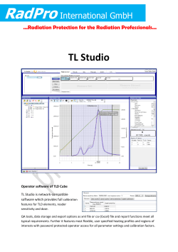


© Copyright 2026