
English
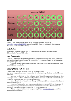
English
Owner’s Manual
Panel Descriptions
Rear Panel
Editing the Parameters
A
1
3
B
C
D
E
Here’s how to make settings for the SBX-1.
1. Hold down the [q] button and press the [CLOCK SOURCE] button.
The D-SYNC indicator and the MIDI indicator light, and the display indicates the parameter name.
2. Use the [TEMPO] knob to select a parameter.
4
3. Press the [CLOCK SOURCE] button; the value of the selected parameter is shown.
4. Use the [TEMPO] knob to edit the value.
5. Press the [CLOCK SOURCE] button to return to the parameter selection state.
6. Press the [q] button to return to normal operation.
A Turning the power on ([POWER] switch)
Controller
[POWER] switch
2
5
1 DIN SYNC
Switches the synchronization signal setting (SYNC 24, SYNC 48) of the DIN SYNC connectors (IN, OUT 1, OUT 2).
2 CV/GATE OUT
Connect an analog synthesizer to these jacks.
CV jack
[TRANSPOSE] switch
GATE jack
[POLARITY] switch
BEND jack
[WHOLE/OCT/LFO]
switch
AUX jack
[1/2/3] switch
Explanation
Controls the pitch. Outputs 0–+5 V.
If the [TRANSPOSE] switch is set to L (Low), this outputs -1–+4 V.
This jack supports OCT/V (it does not support Hz/V).
Switches the pitch range of the MIDI notes that are input.
Relative to M (Mid), you can specify ±2 octaves L (Low) or H (High).
Controls note-on/off.
Outputs +5 V when using USB bus power, or +9 V when using the AC adaptor.
Switches the polarity of the voltage (
).
Outputs ±1 V.
Selects the setting of the BEND jack.
WHOLE: Sets the variable range of the pitch bend to ±1 whole tone.
OCT: Sets the variable range of the pitch bend to ±1 octave.
LFO: Outputs an LFO in a maximum range of ±1 V.
Outputs the CV (control voltage: 0–+5 V) specified by the AUX (1–3) parameters.
The AUX (1–3) parameters can be adjusted individually.
Choose the setting of the AUX jack from AUX 1–3.
3 CLOCK SOURCE
Explanation
This turns the power on/off.
* After you have made the correct connections, be sure to turn on the master device first, and then the slave
devices (or amp).
If you turn on the power in the incorrect order, you risk malfunctions or damage to your equipment. When
turning the power off, first turn off the slave devices (or amp) and then turn off the master device.
* This unit is equipped with a protection circuit. A brief interval (a few seconds) after turning the unit on is
required before it will operate normally.
* With the factory settings, the unit’s power will automatically be switched off 240 minutes after you
stop playing or operating the unit.
If you don’t want the power to turn off automatically, change the “A-oF (Auto Off )” setting to “oFF (Off )”
as described on “Editing the Parameters”
NOTE
• Any settings that you are in the process of editing will be lost when the power is turned off. If you have any
settings that you want to keep, you should save them beforehand.
• To restore power, turn the power on again.
Jack
DC IN jack
Explanation
Connect the included AC adaptor here. Use only the included AC adaptor.
Use a commercially available USB cable to connect this port to your computer.
This lets you transfer USB MIDI data. It is normally unnecessary to install a driver.
If you are connecting multiple units to your computer, you will need to set the USB
Driver Mode (USb.d) to Advance (Adv) and install the USB driver.
Download the USB driver from the Roland website. For details, refer to Readme.htm
which is included in the download.
& http://www.roland.com/support/
When connected via USB, signals from the DIN SYNC IN connector and the MIDI IN
connector are sent to the computer.
& “Signal Flow When a Computer Is Connected”.
USB (O)port
Controller
MIDI OUT 2
connector
Display
[TEMPO] knob
[FINE] knob
[SYNC] button
[SHUFFLE] button
[TAP] button
Explanation
When the CLOCK SOURCE is INT (INTERNAL), this indicates the tempo.
If something other than INT (INTERNAL) is selected, this shows “----.”
When you’re editing settings, this shows the parameter name or value.
Adjusts the tempo (20.0–300.0).
Use the [FINE] knob to adjust the tempo value below the decimal point.
Press the [SYNC] button if synchronization has been lost.
Synchronized playback will stop while you hold down the button, and will resume
on the next beat when you release it.
Specifies shuffle. The indicator blinks while this is specified.
To adjust the amount of shuffle, press the [SHUFFLE] button and then turn
the [TEMPO] knob (-50–0–50). The setting is finalized when you press the
[SHUFFLE] button once again.
The indicator is lit if the value is other than 0.
* Shuffle will not be on if the value is 0.
If the CLOCK SOURCE is INT (INTERNAL), you can specify the tempo by pressing the
[TAP] button at the desired interval (tap tempo).
5 PLAY/STOP
Starts/stops synchronized playback (when CLOCK SOURCE is INT (INTERNAL)).
Controller
[q] button
[r] button
Explanation
Stops synchronized playback.
When you press the [r] button, the indicator lights and synchronized playback
begins.
When you press the [r] button again, the indicator blinks and synchronized
playback stops.
When you press the [r] button once again, the indicator lights and
synchronized playback resumes from the location at which it stopped.
Tempo Display Mode
dIAL
Tempo Dial Mode
MId.1
MIDI Routing : MIDI
OUT 1
MId.2
MIDI Routing : MIDI
OUT 2
CH .C
CH .A
CH .b
oUt.C
oUt.A
bnd.r
bnd.S
Prt.S
trnS
4 TEMPO/SYNC
Here you can change the tempo and make synchronization settings.
dISP
Connector
MIDI OUT 1
connector
Value
Explanation
Specifies the MIDI channel that will control the
MIDI Ch: CV/GATE
output signals of the CV/GATE jacks.
Specifies the MIDI channel that will control the
oFF, 1–16,
MIDI Ch: AUX (1–3) *1
output signal of the AUX jack (1–3).
oMnI (omni)
Specifies the MIDI channel that will control the
MIDI Ch: Bend
output signal of the BEND jack.
Selects the function of the CV jack and GATE jack.
CvGt:The jacks operate as CV/GATE jacks.
Output Mode: CV/GATE CvGt, trG
TrG:The jacks output a trigger when a
specific note is received.
Specifies the message that is output from the AUX jack (1–3).
Output Mode: AUX
trG (Trigger), vEL (Velocity), Aft (After Touch), LFo (LFO), CC.1–
(1–3) *1
CC.31, CC.64–CC.95 (CC#1–31, 64–95)
Specifies the pitch bend range that is mixed into the
Bend Range for CV
output signal from the CV jack.
oFF, 1–24
* When oUt.C is set to CvGt
Specifies the speed at which to interpolate between
oFF,
Bend Mode for CV
FASt (FAST), MId the received pitch bend messages.
(MID), SLow (SLOW) * When oUt.C is set to CvGt
Specifies the portamento on/off setting for the CV jack.
oFF:
OFF
Portamento SW for CV on:
Portamento is always on.
LEGt:Portamento is applied when you play legato.
* When oUt.C is set to CvGt
Specifies the portamento time for the CV jack.
Portamento Time for CV 0–127
* When oUt.C is set to CvGt
Specifies the reference note when the [TRANSPOSE]
Transpose
-12–12
switch is set to “M” (Mid).
trG.C Trigger Note: CV
trG.G Trigger Note: GATE
D DIN SYNC jacks
Connect a device that supports DIN SYNC to these jacks.
Jack
Explanation
This jack receives Start, Stop, Clock, and Continue Start according to the setting
of the DIN SYNC switch.
DIN SYNC IN jack
DIN SYNC OUT 1 jack
DIN SYNC OUT 2 jack
These jacks transmit Start, Stop, Clock, and Continue Start according to the
setting of the DIN SYNC switch.
About the signals of the DIN SYNC jacks
* These will not work unless you use MIDI cables that support DIN SYNC.
Pin
Pin 1
Pin 2
Pin 3
Pin 4
Pin 5 (*)
Explanation
Start/Stop
GND
Clock
none
Continue Start
Pin 4
Pin 1
trG.A
Trigger Note: AUX
(1–3) *1
LFo.C LFO Waveform: CV
LFo.A
LFO Waveform: AUX
(1–3) *1
LFo.b LFO Waveform: Bend
Pin configuration on the unit
Pin 2
Pin 5
Pin 3
* The operation of Continue Start will differ depending on the device that is connected. Refer to the owner’s
manual of the device that is connected.
E Security slot (N)
& http://www.kensington.com/
FIn.C Fine Tune for CV
Parameter
Prt.t
MIDI IN connector
Max Int Tempo
Min Int Tempo
Scale
C MIDI connectors
Explanation
Indicates the currently selected clock source (D-SYNC, MIDI, USB, INT (INTERNAL)).
CLOCK SOURCE indicator
This blinks in synchronization with the clock interval (quarter note timing).
[CLOCK SOURCE] button The master clock source is switched each time you press the button.
BPM
BPM
SCAL
Connect MIDI devices to these connectors.
Explanation
Sends signals to the DIN SYNC OUT 1/2 jacks, CV/GATE jacks, BEND jack, AUX jack, and
MIDI OUT 1/2 connectors.
When connected via USB, performance data from the MIDI IN connector is output via
USB.
CLOCK and START/STOP follow the CLOCK SOURCE setting of the SBX-1.
Transmits the performance data received via USB and the MIDI IN connector.
CLOCK and START/STOP follow the CLOCK SOURCE setting of the SBX-1.
Only the CLOCK and START/STOP are transmitted from USB.
Performance data from the MIDI IN connector is always transmitted.
Parameter
L-t.C LFO Key Trigger : CV
LFO Key Trigger : AUX
L-t.A
(1–3) *1
L-t.b LFO Key Trigger : Bend
SHFL Shuffle Mode
* If you want to save the settings, long-press the [CLOCK SOURCE] button until the display indicates
“SAVE.”
The settings are also saved when you use the [POWER] switch to turn off the power.
The settings are not saved if you turn off the power by disconnecting the AC adaptor or the USB
cable.
B
Here you can switch the clock source.
Controller
Copyright © 2014 ROLAND CORPORATION
All rights reserved. No part of this publication may be reproduced in any form without the written permission of ROLAND
CORPORATION.
Various Settings
Top Panel
Jack/Controller
Before using this unit, carefully read the leaflet “USING THE UNIT SAFELY.” The leaflet provides important information concerning the
proper operation of the unit. Additionally, in order to feel assured that you have gained a good grasp of every feature of your new
unit, read Owner’s Manual in its entirety. This manual should be saved and kept on hand as a convenient reference.
L-C.C LFO Control: CV
LFO Control: AUX
L-C.A
(1–3) *1
L-C.b LFO Control: Bend
L-d.C LFO Depth: CV
LFO Depth: AUX
L-d.A
(1–3) *1
L-d.b LFO Depth: Bend
L-r.C LFO Rate: CV
L-r.A LFO Rate: AUX (1-3) *1
L-r.b LFO Rate: Bend
bd (36), Sd (38), Lt (43), Mt (47), Ht (50), rS (37), HC (39), CH (42), oH
(46), CC (49), rC (51)
* The value in parentheses indicates the note number.
32n, 32nF (Thirty-second note), 16t, 16tF (Sixteenth-note triplet),
16n, 16nF (Sixteenth note), 8t, 8tF (Eighth-note triplet), 8n, 8nF
(Eighth note), 4t, 4tF (Quarter-note triplet), d8n, d8nF (Dotted eighth
note), 4n, 4nF (Quarter note)
* When oUt.C or oUt.A is set to TrG
* Valid notes are created from the clock specified by CLOCK SOURCE.
* If the indication has no “F” following the note, the trigger is output only
between START and STOP.
* If the indication has an “F” following the note, the trigger is output at
all times.
Specifies the LFO waveform.
trI (TRI), SAw (SAW), Sq 5–Sq 1 (SQUARE 50%–10%), SMPL (Sample
and Hold), SMP2 (CV only)
* When oUt.C or oUt.A is set to LFo
Specifies the LFO waveform.
trI (TRI), SAw (SAW), Sq 5–Sq 1 (SQUARE 50%–10%), SMPL (Sample
and Hold)
* When the [BEND] switch is set to LFO
Select the parameter that is output from each jack.
oFF (OFF), bnd (Bend), vEL (Velocity), AFt (After Touch), CC.1–CC.31,
CC.64–CC.95 (CC#1–31, 64–95)
* If this is OFF, LFO is always output.
Adjusts the 5 V of the CV OUT or the AUX OUT.
* This value will fluctuate slightly if the FIn.C
value is changed.
0–255
MId.d MIDI Device ID
USb.d USB Driver Mode
A-oF
Value
Explanation
Specifies whether the LFO is reset to the beginning of the waveform when
a note-on is received.
oFF : Not reset
on : Reset
16 (shuffle 16th note locations), 8 (shuffle 8th note locations)
Specifies the maximum/minimum tempo value that
can be set when CLOCK SOURCE is INT.
20–300
* Min cannot be set above Max.
Adjusts the 0 V of the CV OUT.
* This value will fluctuate slightly if the SCAL
-25–0–25
value is changed.
Auto Off
Selects the CLOCK SOURCE whose tempo is shown in the display.
Int (INT), ALL (D-SYNC, MIDI, USB, INT)
* The tempo indication is not stable for the CLOCK SOURCE other than
Int.
Specifies the operation of the [TEMPO] knob and [FINE] knob.
* Use the [TEMPO] knob to edit the left side of the indication, and use
the [FINE] knob to edit the right side.
b-F:
BPM & FINE
F-b:
FINE & BPM
b-P:
BPM & PERCENT
Specifies whether data sent from MIDI IN to MIDI OUT1, CV/GATE, BEND,
and AUX jacks is output.
oFF:
Not output.
on:
Output.
AUto:Output if USB is unconnected; not output if USB is
connected.
Specifies whether data sent from MIDI IN to the MIDI OUT2 connector is
output.
oFF:
Not output.
on:
Output.
Specifies the device ID for system exclusive
1–16
messages.
Selects the USB driver.
GEn (Generic), Adv (Advance)
* The setting takes effect the next time a USB connection is made.
Specifies the auto-off setting.
oFF (OFF), 240 (240 min.)
*1To edit each of the AUX jack settings (1–3), set the [1/2/3] switch appropriately before editing the value.
Connection Example
DIN SYNC Master
DIN SYNC
DIN SYNC
OUTPUT
MIDI
D-SYNC IN
TR-808
MIDI OUT 1
SBX-1
* These will not work unless you use MIDI cables that support DIN SYNC.
MIDI Master
TRIGGER
MIDI
-100–0–100
Specify the LFO Depth that is output from each jack.
MIDI OUT
AUX
EXT CLK IN
MIDI IN
TR-8
Specify the LFO Rate (speed) that is output from each jack.
0–100 (0–100), 16t (Sixteenth-note triplet), 16n (Sixteenth note),
8t (Eighth-note triplet), 8n (Eighth note), 4t (Quarter-note triplet), 4n
(Quarter note), 4n-2 (Quarter note x 2), 4n-4 (Quarter note x 4), 4n-8
(Quarter note x 8)
SH-101
SBX-1
TB-303
D-SYNC OUT 1
USB
CV/GATE
Signal Flow When a Computer Is Connected
CV/GATE OUT
SBX-1
Main Specifications Roland SBX-1: SYNC BOX
Power Supply
3. When the display indicates “COMP,” turn the power of the SBX-1 off and then on again.
Current Draw
Dimensions
Weight
Accessories
Options (sold
separately)
AC adaptor, or obtained via USB port (USB bus power)
150 mA (When using an AC adaptor)
200 mA (When using USB bus power)
220 (W) x 135 (D) x 52 (H) mm
8-11/16 x 5-3/8 x 2-1/16 inches
790 g
1 lb 12 oz
Owner’s Manual, AC adaptor, Leaflet “USING THE UNIT SAFELY”
USB cable
* In the interest of product improvement, the specifications and/or appearance of this unit are subject to
change without prior notice.
SBX-1
SH-101
CV/GATE OUT
SBX-1
DIN SYNC IN
USB
CV/GATE OUT
DIN OUT 1/2
MIDI OUT 1
SBX-1 Master
DIN SYNC
D-SYNC OUT
SBX-1
MIDI IN
CV/GATE IN
SH-101
PC/Mac
PC/Mac
Here’s how to return the SBX-1 to its factory-set state.
1. While holding down the [SHUFFLE] button, turn on the power.
The display indicates “rSt” and the [r] button blinks.
If you decide to cancel the factory reset, turn off the power.
2. Press the [r] button to execute the factory reset.
SYNC INPUT
DIN SYNC
USB Master
Restoring the Factory Settings (Factory Reset)
MIDI IN
TB-3
MIDI OUT 2
MIDI OUT
CV/GATE
CV/GATE IN
SYNC
INPUT
TR-808
MIDI
TB-3
MIDI IN
* To prevent malfunction and equipment failure, always turn down the volume, and turn off all the
units before making any connections.


© Copyright 2026