
Document 427862
Jan. 23, 1968
R. G. WILSON ETAL
3,364,845
DEEP FAT PRESSURE COOKER
Filed July 11, 1966
5 Sheets-Sheet l
A
THERMOSTAT
Q 5743
SW3
02%}
INVENTORS.
ROBERT G. WILSON ¢
_ RAYMQND Ml‘. ROGERS
MVW
ATTORNEYS
Jan. 23, 1968
,
R. G. wmsom ETAL
3,364,845
DEEP FAT PRESSURE COOKER
Filed July 11, 1966
5 Sheets-Sheet 2
41'7
1%;
2A.
‘ IINVENTORS.
ROBERT 6. WILSON ¢
BYRAYMOND W ROGERS
MVW
.4 TTORNEYS
Jan. '23, 1968
3,364,845
R G. WILSON ETAL
DEEP FAT PRESSURE COOKER
Filed July 11, 1966
5 Sheets-Sheet 5
/74 I
£72
27
Jo v36 26
E
I | ‘
0
0
IN VEN TORH.
ROBERT c. WILs0N¢
By RAYMOND W ROGERS
wwxkg
ATTORNEYS
Jan. 23,, 1968
_
R. G. WILSON ETAL
3,364,845
DEEP FAT PRESSURE COOKER
Filed July 11, 1966
‘5 ‘Sheets-Sheet 4
74
74a
72
r
‘
M42 '
\w/ 65
E “/ I5
35 53
35a
32
r17
' 5 '~'
'
>
INVENTORS.
ROBERT G. WILSON ¢
f BY RAYMOND W‘. ROGERS
ATTORNEYS '
Jan. 23, 1968
R. 6. WILSON ETAL
7
3,364,845
DEEP FAT PRESSURE COOKER
Filed July 11, 1966
5 Sheets-Sheet 5
/ ——————— ——/ ——————————————————————— "#5
6 P2 Gas {ER/‘405% p,
‘P1 i
"2W
|
.28
/
CH4
HEAT/N6 CIRCUIT
~——1
3
_
L'ZZ
O
5,2
DOWN O/Rcu/T
‘
L'P
(CR ‘I
‘ [A LTOIRJ,
j I
MOTOR CIRCUIT
cR-zz
16;
5T,
RS2
w
CR2
50
7:15
R
L44
?g up CIRCUIT
_
L'3
r,
|__
P51
(
CR-Za
_
/
,L
Q2,
Q01
1/
(T3
1
1G}
~( 5W3
'_®—'
COMPRESSOR
c/Rcu/T
, PRESSURE
RELEASE c/Rcu/T
.
‘
PS -3
'
LATCH CIRCUIT
~
5
IN VEN TOR.
ROBERT 6. WILSON ¢
BY RAYMOND W ROGERS
ATTORNEYS
United States Patent 0 ice
1
3,364,845
DEEP FAT PRESSURE COOKER
Robert G. Wilson, 643 E. Faris Road, and Raymond W.
Rogers, 414 Potomac Ave., both of Greenville, S.C.
29605
Filed July 11, 1966, Ser. No. 564,102
9 Claims. (Cl. 99—336)
This invention relates to deep fat pressure cookers,
3,364,845
Patented Jan. 23, 1968
2
- The invention will be more readily understood from a
reading of the following speci?cation and by reference to
the accompanying drawings forming a part thereof, where
in an example of the invention is shown and wherein:
FIGURE 1 is a perspective view, with parts broken
away, illustrating a deep fat pressure cooker constructed
in accordance with the present invention,
FIGURE 2 is a transverse sectional elevation further
illustrating the device shown in FIGURE 1,
and more particularly to an automatic cooker wherein an
FIGURE 2A is an enlarged perspective view illustrat
10
effective seal may be maintained between the cover and
the pot, and wherein condensation upon the cover will
?ow down the cover into the pot to avoid contamination
of the food and the exterior of the cooker. A preferred
ing the cover and associated parts,
FIGURE 3 is a rear elevation of the preferred embodi
ment of the pressure cooker illustrated,
FIGURE 3A is an enlaroed transverse sectional eleva
embodiment of the invention further contemplates easy 15 tion of the cover for the cooker,
loading of the food for uniform cooking.
FIGURE 4- is a side elevation of the device taken from
Heretofore, deep fat pressure cookers have been con
the right-hand side of FIGURE 1,
structed wherein, upon the completion of a cooking oper
FIGURE 5 is a perspective view illustrating the details
ation, it is necessary for the operator to open the cover I of an edible support basket,
and then remove baskets containing the edible being 20
FIGURE 6 is a perspective elevation of a modi?ed
cooked from the hot grease. In loading such cookers it
form of an edible support basket, and
is necessary to place the edible in the baskets and then
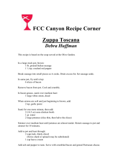
FIGURE 7 is a schematic wiring diagram illustrating
place the baskets manually into the grease and then close
the operation of various electrical components.
the cover manually. In many cooking establishments the
The drawings illustrate a deep fat pressure cooker in
operator must attend to other duties, as well as the oper 25 cluding a heated pot for containing hot cooking fat where
ation of such cooker, so that it is likely that he might
ing, the pot has an opening in an upper portion thereof
fail to remove the edible from the grease at the end of
de?ned by an annular surface A which tapers inwardly
a desired cooking cycle causing the food to burn. While
downwardly from an upper portion thereof. A centrally
automatic deep fat pressure cookers have been provided,
disposed vertical shaft B has a lower portion extending
such have required the placing of the food in baskets 30 through and below the pot. A substantially horizontal
prior to loading the machine, and otherwise have de?cien
cover has a central connection on an upper portion of the
cies which are remedied by devices constructed in accord
vertical shaft. A lower surface C of the cover includes, a
ance with the present invention as discussed below.
?rst conical marginal surface converging inwardly down
Accordingly, it is an important object of this invention
wardly from an upper portion thereof complementary to
to provide an automatic machine for cooking in deep fat 35 the annular surface A of the opening in the pot, and a
under pressure which requires a minimum of operator
bottom surface de?ned by a second conical surface e. attention.
tending from a lower portion of the ?rst conical marginal
Another important object of this invention is to provide
an improved cover and basket arrangement whereby an
surface converging inwardly downwardly toward the
shaft. A foraminous basket D is provided for carrying
effective seal might be maintained between the cover and 40 edibles. Mounting means E is carried on the shaft spaced
the pot when pressure is maintained within the pot.
Another object of the invention is to avoid contam
ination of the machine and the cooked food by grease
splattering and moisture drippings as the cover is raised.
Still another important object of the invention is to
provide a cover and central shaft combination wherein
the cover is provided with a guide for facilitating posi
tioning and raising of the cover.
It is another important object of the invention to pro
vide means for positioning the shaft and cover assembly
and the edible supporting baskets carried thereby in an
intermediate position wherein food may be placed in the
basket after the basket is at least partially submerged in
below the cover for removably supporting the basket.
Means F are connected to the lower portion of the shaft
for raising the shaft from a position wherein the mar
ginal surface of the cover is positioned adjacent the an
nular surface for effecting a seal therebetween to a posi
tion wherein the basket may be placed upon the mounting
means, and for lowering the shaft to return the cover to
effect such seal and place the basket and edibles therein
into the hot fat. Thus, an effective uniform seal may be
had between the cover and the pot, and condensation
upon lower surface of said cover will flow downwardly
thereof toward the shaft and be thence returned to the
pot.
hot fat.
The heated pot is broadly designated at 10. An out
55
Still another important object of the invention is to
wardly extending ?ange or rim 11 extends from the top
provide a pot adapted to receive heating elements in a
thereof over the cabinet top 12 which has a circular open
position to more uniformly heat the deep fat, and yet
ing 13 therein to accommodate a pot wall 14. A cabinet
accommodate a maximum amount of edibles within the
is formed by the top 12 which is carried by vertical mem
cooker.
bers 15 illustrated as being positioned adjacent each
Still another important object of the invention is to
corner thereof. The vertical members 15 carry an inter
provide automatic means for raising the cover associated
mediate supporting portion 16 and a base portion 17.
with mechanical means for insuring the safe raising of the
Suitable legs are illustrated at 18.
cover which must be accomplished with the pressure off
The pot 10 has an opening in the upper portion there
of the pot.
of
which is de?ned by the annular outwardly tapering
Yet another important object of the invention is to pro 65 surface A. The pot wall 14 includes neck portion 14a
vide an improved system for ?ltering the grease within
(FIGURE 2) extending downwardly from the annular
the pot for insuring cooking operations with a minimum
surface A. A recessed or enlarged Wall portion 14!: ex
of grease contamination for improved ?avor.
tends downwardly from the neck portion 14a and joins a
The construction designed to carry out the invention
70 dished out bottom portion 140. The heating elements for
will be hereinafter described, together with other features
the pot are illustrated in FIGURES 2 and 7 at R1, R2
thereof.
and R3. It will be observed that the heating elements
3,364,845
are con?ned to the recessed portion of the tank de?ned by
the wall portion 14b, so as to be spaced vertically within
the pot to provide uniform heating for the cooking liquid
19 contained therein, and yet permit a maximum amount
of edibles to be carried within the pot. Since the neck
portion of the wall 14a extends inwardly of the heating
elements, a protective shield is formed thereby against
damage which might occur should a basket carrying
edibles strike a heating element. It should be observed that
the neck portion 14a is joined to the recess portion 14b
by an outwardly extending integral wall 14d.
The hollow vertical shaft B has a lower portion ex
tendin-ty through said pot. The lower portion of the pot has
4
The baskets are positioned upon mounting means -E,
which preferably includes a depending rod 33 mounted
upon a collar 33a which has suitable mounting (not
shown) upon the shaft E. The vertical rod carries a
projecting head 34 which is carried in spaced relation to
the rod 33 upon a connecting shank (not shown) which
thus mounts the head upon the rod. The head 34 is accom
modated within an enlarged portion 35a of a narrow verti
cal slot 35 within the vertical support 32. Such an ar
rangement might best be used in an establishment where
large quantities of food of limited kinds, such as French
fries and chicken, are to be cooked at one time in the
opposed relatively deep baskets.
-
. a boss 142 which receives a bearing broadly designated
A modi?ed form of basket support E is illustrated in
received within an annular bore 21 within the ‘boss Me
and includes an upper portion 22 which is provided with
O-rings 23 to provide an effective seal between the bear
ing and the vertical shaft B. The bearing 20 includes a
lower housing section 24 which carries a ball bearing 25
dentions 36 conform to vertically spaced‘ aligned U
shaped frame members 37 of the relatively shallow basket
at 20 for accommodating the shaft B. The bearing 20 is 15 FIGURE 6 wherein vertically spaced pairs of aligned in
D. The U-shaped frame members de?ne an opening 38
so the basket may be received upon the vertical shaft B
and positively positioned thereon with a minimum of 0p 7
shaft B as will be described below.
The cover broadly designated at 26 has a lower sur
face C which includes a ?rst conical marginal surface 27
which converges inwardly downwardly from an upper
erator effort. Preferably, the indentions 36 do not pass
entirely about the shaft B but are placed on opposite
sides thereof to prevent the circular baskets D illus
trated in FIGURE 6, from turning thereon because of
the stops 36a thus formed. As illustrated, several vertical
ly spaced baskets may thus be carried upon the shaft B.
Since limited amounts of edibles would be pre-loaded in
each basket the sticking problem referred to above would
portion thereof complementary to the annular surface A
de?ning the opening in the pot. The surface 27 is grooved
useful in restaurants where several kinds of food, such as
therein. The lower portion 24 is held in place by the
elongated screws 26 which extend upwardly into the boss.
The bearing 25 serves as a part of the rotatable mounting
for the shaft B used in raising and lowering the vertical
be avoided. Such basket arrangement would be especially
as at 27a to accommodate an O-ring 28 in an intermediate
steaks, chicken, ?sh, etc., may be loaded in respective
portion thereof, and a bottom surface 29 extends there
baskets and cooked at one time.
from in the form of a second conical surface and con
verges inwardly downwardly toward the shaft B which is
suitably connected thereto as by the setscrew 26a (FIG
URE 2) or as by welding (not shown). The ?rst conical
surface 29 and second conical surface 29 could be continu
Means 'F is connected to the lower portion of the shaft
B for raising and lowering the shaft. The means F in
cludes a hollow cylindrical member 38 (FIGURE 2)
which has an upper t?ange 39 which is carried for rota
tion by the ball bearing 25. The cylindrical member 38
has a sheave 39 (FIGURES 1 and 2) mounted in ?xed
position thereon. The sheave 39 is driven by the belt 40
vided for snug engagement with the upper rim 11 of the
pot and to guide the condensation upon the lower surface 40 which is in turn driven by a sheave 41 carried by the
power takeoff shaft 42 of the motor M. The hollow
C toward the central of the pot to avoid contaminating
cylindrical member 318 carries a plug 43'?xed therein by
food within the baskets and to avoid splashing grease and
setscrews 44. The plug carries a vertical threaded mem
water over the top of the cooker. Preferably, the surface
ber 45 which is received within an internally threaded
29 is unobstructed and smooth to further facilitate the pas
plug 46 which is carried within the lower portion of the
sage of condensation thereon.
hollow shaft B and suitably secured therein as by weld
It will be observed that the baskets D are preferably
ing (not shown). The direction of the motor M may be
spaced considerably below the lower surface C of the
reversed for raising and lowering as described below.
cover to avoid obstruction so that unobstructed access is
It will be observed that an outlet pipe 47 is provided
provided for dropping the edibles within the baskets D.
in the dished out bottom portion 140 and that a valve ?t
Thus, with the basket D in an intermediate position, as
ting 48 may be secured therein releasing the grease with
illustrated in broken lines in FIGURE 2, with the lower
in the pot into a suitable ?lter element broadly desig
portion of the basket submerged in the grease 19, part
nated at 50. The valve has a suitable operating handle
of the edibles may be added at a time to avoid sticking
49. The ?lter 50 includes an open tank '51 having a hori
together during cooking. For example, in the case of
fried chicken, it is desirable that the pieces be placed . zontal support 52, preferably of expanded metal, ,posi
tioned in an intermediate portion thereof, and a porous
separately within the basket to prevent them from stick
‘?lter 53 is positioned above. The grease is collected within
ing together during the cooking process. During the cook
ous rather than broken so long as a suitable surface is pro
the lower portion of the tank 51 and recirculated through
ing process the pressure developed in the pot seals the
the line 54 by the pump P, which includes a suitable
edible and keeps in the juices and adjoining pieces to be
motor 55 (FIGURE 1). From the pump P the grease may
sealed together in the process. This is avoided by sealing
pass through the line 56 into the pot 10 through a suit
the outside of each piece as it is thus added. It will be
able opening (not shown) in the upper portion of the pot.
observed that FIGURE 1 shows the shaft B and the basket
Operationv
carried thereby in fully raised position for unloading
baskets or in position having just received the baskets.
Starting with the shaft B in fully raised position as
FIGURE 2 in full lines illustrates the baskets in cooking 65 shown in FIGURE 1 and with the baskets positioned
upon the mounting means E, the operator ?rst closes the
position.
circuit breaker LS located on the front panel of the
The baskets D (FIGURE 5) are constructed from ex
machine to energize the circuitry. Referring to FIGURES
panded metal or other suitable foraminous material. Such
1 and 7, it will be noted that if the operator then depresses
basket, according to a preferred embodiment, includes a
the down or start switch SW1, power will be placed on
pair of vertical spaced semi-circular frame members 30
control relay CR~1. Such energization causes contacts
with extended metal 31 therebetween. A semi-circular
CR-ll to close sealing in a circuit around the start switch
vertical support 32 is carried by the frame members 30 to
SW1. The control relay contacts CR-12 are in series with
be received upon the shaft B and the mounting means E
carried thereby.
the motor M so that the cover 216 will be lowered there
3,364,845
by; A depending rod 60 (FIGURE 4) is carried by the
cover and is suitably fastened thereto as by the link 61.
The rod extends downwardly through a guide 62 within
the cabinet top 12 and carries a cam 63 adjacent the lower
end thereof. The cam or abutment 63 opens the normally
closed microswitch L1 to de-energize control relay CR-I
causing contacts CIR-11 and CR-lz to open stopping the
motor.
5
3 and 7). The switch PS3 is set to actuate a solenoid S
mounted in the central portion of the cover 26 when the
pressure reaches a safe level but has not yet quite re
turned to “zero” (atmospheric). A horizontal plate 68 is
pivoted as at 69. A spring 7t) has connection on one end
as at 7 ila with the plate and on the other end as at 7% to
the cover and urges the plate to push in the core of the
solenoid S through linkage 71 carried by the plate. A rod
72 is carried by the plate 68 and is positioned in locking
illustrated in broken lines in FIGURE 2, for loading
position beneath the latch members 73. When the pres
edibles thereon as described above. The operator sets the 10 sure falls below the safe level the solenoid is actuated ex
normally open timer T, opening contacts T1 and T3 and
tending its core against the force of the ‘spring 70 to
closing contacts T2, and depresses the down switch SW2
move the latch arm 72 into released position. A cover
The baskets D are now in intermediate position, as
placing power on the control relay CR~1 causing con
74 is provided to house the solenoid S and associated
tacts CR~12 to again be closed energizing the motor M.
parts. Slots as illustrated at ‘Ma (FIGURE 4) are pro
Simultaneously contacts CR—13 are closed sealing in the 15 vided to accommodate the ends of the rod 72.
circuit around SW2 thus completing the circuit across B
If desired, the latch mechanism described above could be
and R leads through contacts CR-13, timer contacts T2,
constructed toclose responsive to actuation ‘by a solenoid
relay OR-l and limit switch L-22. The motor is now
such as the one illustrated at S. If this is done the spring
running causing the top 26 to be lowered until the cam
would be attached to the opposite side of the plate to
63 strikes the microswitch L-22 opening same. When the
normally urge the rod 72 to open position rather than
microswitc'h L-22 is opened the control relay CR-"l is de
closed position as illustrated. The switch ‘PS-‘3 in such
energized causing contacts CR-lz in the motor circuit to
situation would be normally open and would close when
open stopping the motor M. The microswitch L-21 was
also closed by the cam 63 and this completed a circuit ‘be
tween leads W and B to a compressor CO through 21 nor
mally closed pressure switch PS-l (FIGURE 3) ener
gizing the compressor until a predetermined pressure is
‘built-up in the pot 10, as described below, at which time
the pressure in the pot exceeded said safe level to actuate
25 the solenoid.
It should be noted that the compressor CO introduces
air into the pot through the line 75 through the opening
76 within the pot. ‘Such air also passes through a mani
fold 77, communicating with the opening 76, and which
PS-l opens the compressor circuit.
30 carries the valves PS-I, PS-Z and PS—3. The manifold is
The thermostat has been previously set a suf?cient
connected through a line 78 to a pair of pressure relief
time to cause the fat to heat to the desired temperature.
valves 79 and 84). One of these pressure relief valves is
To accomplish this the thermostat, which is connected in
calibrated to open at a pressure slightly above the de
series with control relay CR-3, causes contacts CR-31 to
close energizing the calrod heating elements R1, R2, and
R3 when the temperature drops below a preset level as
sired cooking pressure within the pot for safety purposes
35 preventing an excessive build-up of pressure as might
control relay CR-2 to be partially completed. The clos
occur if the compressor is not properly deactivated at
the level for which the pressure sensitive switch PS—1
is set. The line 81 from valves 79 and 8t} delivers the
air to the release condenser 65. The second valve 80 is
simply an additional safety factor and is calibrated to
open at a slightly higher pressure than the valve 79.
While a preferred embodiment of the invention has
ing of contacts T3 causes solenoid valve SV-l to be ener
been described using speci?c terms, such description is
determined by the sensing bulb U within the pot (‘FIG
URE 2).
The cooking operation continues until the timer T times‘
out and two sets normally closed contacts T1 and T3
are closed. The timer contacts T1 cause the circuitry to
gized which permits air and vapor to escape from the pot
through the line 64 into the condensation chamber 65.
From the condensation chamber the condensate passes
through the line 66 into a receptacle 67.
When the pressure drops to “zero” a safety pressure
switch PS-Z is closed completing the circuit to control
relay CR~2 through the timer contacts T1 and the closed
microswitch .L—4 which was previously closed by the
cam 63.
The top must now be raised at the completion of the
cooking operation and when control relay CIR-2 is ener
gized contacts CR-22 are closed energizing the circuit to
the motor causing the motor to run in a clockwise di
rection raising the cover and shaft assembly. The contacts
CR-Zs close acting as a sealing circuit about the micro
switch L-4. The motor runs until the limit switch L-3 is
opened by contact with the cam 63 in raised position.
The contacts of switch L-3 cause control relay CR-2 to
be opened.‘
7
for illustrative purposes only, and it is to be understood
that changes and variations may be made without depart
ing from the spirit or scope of the following claims.
What is claimed is:
1. A deep fat pressure cooker comprising, a heated
pot for containing hot cooking fat, said pot having an
opening in an upper portion thereof de?ned by an annular
surface which tapers inwardly downwardly from an up
er portion thereof, a centrally disposed vertical shaft
having a lower portion extending through and below said
pot, a substantially horizontal cover having a central con
nection on an upper portion of said vertical shaft, said
cover including, a ?rst conical marginal surface converg—
ing inwardly downwardly from an upper portion thereof
complementary to said annular surface of the opening in
the pot and a bottom surface of said cover de?ned by a
second conical surface extending from a lower portion of
said first conical marginal surface converging inwardly
It should be noted that by depressing the switch STI
the shaft B may be stopped in any desired position by the
opening of its contacts 8T1 and v5T2 in the up and down
downwardly toward said shaft, a foraminous ‘basket for
carrying edibles, mounting means carried on said shaft
spaced below said cover for remova'bly supporting said
circuits, respectively. By depressing switch SW1 the shaft
basket, and means connected to said lOWer portion of
the shaft for raising said shaft from a position wherein
may then be lowered or by pressing the switch SW the
shaft may be raised. The pilot light P1 shows power on
the thermostat, while the pilot light P2 shows power on
the circuit. By closing the switch SW3 the pump P will be
the marginal surface of the cover is positioned adjacent
said annular surface for effecting a seal therebetween to
a position wherein said basket may be placed upon said
energized to ?lter the fat in the pot as described above.
mounting means and for lowering the shaft to return the
cover to eifect such seal and place the basket and edibles
Safety latch
therein into the hot fat, whereby an effective uniform
FIGURE 2A illustrates a safety latching mechanism
seal may be had between the cover and the pot, and
operated by a pressure sensitive switch PS—3 (FIGURES 75 whereby condensation upon lower surface of said cover
3,364,845
‘2'
will ?ow down the second conical surface toward the
shaft and be thence returned to the pot.
2. The Structure set forth in claim 1 including, a ver
tical guide for said vertical shaft, whereby said cover and
shaft will be guided during raising and lowering thereof.
3. The structure set forth in claim 1, wherein said
mounting means includes an enlarged head carried by
said vertical shaft in ?xed spaced relation thereto, and
said basket has a slot for receiving said head.
8
.
for positioning said assembly in an intermediate position
wherein a lower portion of the basket is submerged in the
hot cooking fat for receiving edibles placed therein part
at a time, said basket being positioned substantially be—
low said cover for receiving edibles into the basket when
said basket is positioned upon said assembly to avoid said
edibles from sticking together, and third power control
means for positioning said assembly in fully closed posi
tion wherein said cover is closed over the opening in
4. The structure set forth in claim 1, wherein said 10 the pot and said ‘basket is further lowered into the cook
mounting means includes spaced aligned indentions in
said shaft, and said basket has spaced aligned members
ing fat for cooking under pressure.
'
8. The structure set forth in claim 7, wherein said
shaft means is a centrally disposed shaft passing through
to be received in said indentions.
the pot, and wherein said basket is carried by the shaft.
5. The structure set forth in claim 1 including, means
9. A deep fat pressure cooker comprising, a heated
for discharging the fat from said pot, a ?lter for receiv 15
pot for containing hot cooking fat, said pot having an
ing the fat thus discharged, and a pump returning the
opening in an upper portion thereof, a cover for said
fat from the ?lter into the pot.
pot, a vertical shaft for raising and lowering said cover
6. A deep fat pressure cooker comprising: a pot for
connected to said cover so as to form an assembly there
containing hot cooking fat including; an opening in an
with, power operated means positioned below the opening
20
upper portion thereof de?ned by an annular'surface which
in said pot for raising and lowering said assembly, a
tapers inwardly downwardly from an upper portion there
foraminous edible carrying basket carried by said assem
of; a centrally disposed vertical shaft having a lower
bly, means for building up air under pressure in said pot.
portion extending through and below said pot; a substan
when said cover is closed over said opening, a ?xed latch
tially horizontal cover having a central ?xed connection
carried in ?xed relation to said pot, a movable member
25
on an upper portion of said vertical shaft; said cover
engaging said ?xed latch carried in ?xed relation to said
including; a ?rst conical marginal surface converging in
assembly, a solenoid mounted adjacent to said movable
wardly downwardly from an upper portion thereof com
member, and a pressure sensitive switch operating respon
plementary to said annular surface of the opening in the
sive to pressure conditions within the pot connected to
pot, and a bottom surface of said cover de?ned by a
said solenoid to cause said solenoid to move and disen
second conical surface extending from a lower portion of 30 gage said movable member from said ?xed latch, where
by the movable member engages the said ?xed latch
downwardly toward said shaft; a foraminous basket for
positively maintaining the cover in closed position when
carrying edibles; mounting means carried on said shaft
pressure conditions obtain within the pot making it dan
spaced below said cover for removably supporting said
gerous to raise the cover.
basket; said pot further including, a lower recessed por 35
tion, and a plurality of vertically spaced heating elements
References Cited
carried in said recessed portion; and means for raising said
UNITED STATES PATENTS
shaft from a position wherein the marginal surface of
the cover is positioned adjacent said annular surface for
1,986,115
1/1935 Offenhauser _______ .__ 99—349
effecting a seal therebetween to a position wherein said 40 1,993,507
3/1935 Flegel ___________ __ 49-2 XR
basket may be placed upon said mounting means and
2,191,275
2/1940 Fink __________ __ 99-407 XR
for loweging the shaft to return the cover to effect such
2,408,248
9/1946 Barber ________ .__ 99—336 XR
seal and place the basket and edibles therein into the
2,427,564 9/ 1947 Le Claire.
hot fat; whereby an effective uniform seal may be had
2,568,792
9/1951 Cripps ________ -__ 99—407 XR
between the cover and the pot, and whereby condensa 45 2,635,628
4/1953 Stamper ______ __ 137—-525 XR
said ?rst conical marginal surface converging inwardly
tion upon lower surface of said cover will flow down the
second conicalsurface toward the shaft and be thence re
turned to the pot.
7. A deep fat pressure cooker comprising, a heated 50
pot for containing hot cooking fat, said pot having an
2,700,724
2,756,321
2,914,063
1/1955
7/1956
11/1959
Lynch ____________ __ 2l9—433
Pappas ________ __ 99-—403 XR
Wagner __________ .__ 126-381
2,938,648
5/1960
Phelan et a1. _____ 220»——57 XR
6/ 1960
8/1961
Kelton ____________ __ 220-33
Phelan et a1. _______ __ 99—332
Jennings __________ -__’ 99—329
opening in an upper portion thereof, a cover for said
2,942,753
2,997,941
pot, vertical shaft means for raising and lowering said
3,187,664
6/1965
cover connected to said cover so as to form an assembly
3,209,673
10/1965
Howard ___________ __ 99-—251
therewith, power operated means positioned below the
opening in said pot for raising and lowering said assem
bly, a foraminous edible carrying basket carried by said
assembly having an opening therein spaced below said
3,217,633
11/1965
Anetsberger _____ 99——408 XR
3,225,681
12/1965
Wells _____________ __ 99-336
cover, mounting means for positioning said basket upon
said assembly, ?rst power control means for positioning 60
said assembly in fully raised position wherein said basket
may be removed from and placed upon said mounting
means, second power control means including a switch
2,778,736
965,462
168,100
1/1957 Wagner.
FOREIGN PATENTS
7/ 1964 Great Britain.
8/1959 Sweden.
BILLY J, WILHITE, Primary Examiner.


© Copyright 2026