
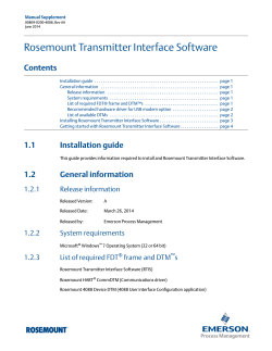
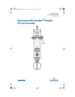
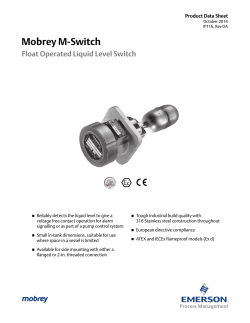
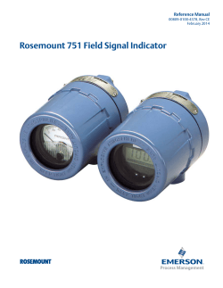
Rosemount 848T High Density Temperature Measurement Family Product Data Sheet
Product Data Sheet November 2014 00813-0100-4697, Rev NA Rosemount 848T High Density Temperature Measurement Family Innovative temperature measurement for high density applications that provide installation and operational savings Independently configurable inputs that support RTD, thermocouple, ohm, mV, 0-10 volt, and 4–20 mA signals Enclosure options and intrinsically safe design allows for installation close to any process, including hazardous areas WirelessHART® capabilities extends the full benefits of PlantWeb® to previously inaccessible locations Industry first Measurement Validation diagnostic can identify a variety of process concerns including sensor degradation, sensor wiring connectivity, high vibration (affecting the measurement), and abnormal process variations. Rosemount 848T Family November 2014 High Density Temperature Measurement Smart Wireless delivers innovative wireless solutions for temperature measurement Self-organizing network delivers information rich data with >99% data reliability and establishes a highly stable network IEC-approved WirelessHART protocol Emerson SmartPower™ Solutions provide an intrinsically safe Power Module, allowing field replacements without removing the transmitter from the process, keeping personnel safe and reducing maintenance costs Emerson Process Management’s layered approach to wireless network security ensures that data transmissions are secure FOUNDATION™ fieldbus provides effective measurements with reduced wiring costs Internationally recognized Digital Network (IEC 61158) supports the connection of up to 16 devices on a single twisted wire pair Allows advanced computations through use of function blocks Provides continuous measurement status for each measurement point Lower costs by reducing wiring, terminations, and required number of I.S. Barriers Explore the benefits of a complete point solution from Rosemount Temperature Measurement Emerson offers a selection of RTDs and thermocouples that bring superior durability and Rosemount reliability to temperature sensing A broad thermowell offering meets the demanding requirements of a variety of process applications Contents Rosemount 848T FOUNDATION fieldbus Temperature Transmitter Rosemount 848T Wireless Temperature Transmitter . . . . . . 24 ................................................. 5 WirelessHART... the Industry Standard . . . . . . . . . . . . . . . . . 26 Specifications . . . . . . . . . . . . . . . . . . . . . . . . . . . . . . . . . . . . . . 8 Specifications . . . . . . . . . . . . . . . . . . . . . . . . . . . . . . . . . . . . . 27 Product Certifications . . . . . . . . . . . . . . . . . . . . . . . . . . . . . . 14 Product Certifications . . . . . . . . . . . . . . . . . . . . . . . . . . . . . . 33 Dimensional Drawings . . . . . . . . . . . . . . . . . . . . . . . . . . . . . . 20 Dimensional Drawings . . . . . . . . . . . . . . . . . . . . . . . . . . . . . . 35 2 www.rosemount.com November 2014 Rosemount 848T Family Experience global consistency and local support from worldwide Rosemount Temperature manufacturing sites World-class manufacturing provides globally consistent product from every factory and the capacity to fulfill the needs of any project Experienced Instrumentation Consultants help select the right products for each temperature application An extensive global network of Emerson service and support personnel can be onsite when and where they are needed Increase performance with High Density Transmitters Transmit multiple measurements with one set of electronics Mount close to process to reduce sensor wire length and increase measurement reliability Enhance Accuracy with EMI correction, cold junction compensation and device diagnostics Reduce installation costs by as much as 70 percent Avoid unnecessary process shutdowns, on-scale failure related issues, and unsafe process conditions with Measurement Validation Diagnostic Detect measurement abnormalities and take preventive action before shutdown is necessary Determine validity of data points that are outside of alarm limits Identify on-scale failures and take action before process efficiency and safety is compromised Detect abnormally fast process rates of change before alarm state is reached www.rosemount.com 3 Rosemount 848T Family November 2014 High density temperature measurement Ideal solution for taking multiple measurements in close proximity to each other such as: Bearing temperature on pumps and motors Distillation columns Furnaces and boilers Reactors, storage tanks, and many more Simplify installation and reduce wiring costs Eliminate Marshalling Less wire routing and fewer terminations Faster startups with fewer devices Access powerful information with new device dashboards Leverage Human Centered Design practices to create an intuitive user interface Instantly see status and output of each sensor Direct links to graphical diagnostics and troubleshooting help Drastically lower configuration time 4 www.rosemount.com November 2014 Rosemount 848T Family Rosemount 848T FOUNDATION fieldbus Temperature Transmitter The Rosemount 848T offers a low cost solution for high density measurements. The 848T accepts eight independently configurable sensor inputs, and can be mounted close to the process to improve data quality. FOUNDATION fieldbus architecture allows up to 128 temperature measurements to be transmitted on a single H1 fieldbus line. Additionally, the 848T is bus-powered, further reducing the amount of required wiring to install the device. The robust design has proven itself in thousands of successful installations. Capabilities include: Eight independently configurable inputs, including 2- and 3-wire RTDs, thermocouples, mV, 2- and 3-wire ohms, and 4-20 mA signals Industry first Measurement Validation diagnostic Fieldbus functionality with 8 AI blocks, 2 MAI blocks, 4 ISEL Blocks, and backup LAS Capabilities 600 Vdc isolation and integral transient protection Specification and selection of product materials, options, or components must be made by the purchaser of the equipment. See page 27 for more information on Material Selection. Table 1. Rosemount 848T FOUNDATION fieldbus Ordering Table ★ The Standard offering represents the most common options. The starred options (★) should be selected for best delivery. __The Expanded offering is subject to additional delivery lead time. Model Product description 848T High Density Temperature Measurement Family Transmitter output F FOUNDATION fieldbus digital signal (includes AI, MAI, and ISEL function blocks, and Backup Link Active Scheduler) ★ Product certifications(1) Rosemount Junction Box required? I1 ATEX Intrinsic Safety No ★ I3 NEPSI Intrinsic Safety No ★ I4 TIIS Intrinsically Safety (FISCO) Type 'ia’ No ★ TIIS Intrinsic Safety (FISCO) Type 'ib’ No ★ I5 (2) FM Intrinsically Safe Yes ★ I6 (2) CSA Intrinsically Safe No ★ I7 IECEx Intrinsic Safety No ★ IA ATEX FISCO Intrinsic Safety No ★ IE FM FISCO Intrinsically Safe No ★ IF CSA FISCO Intrinsically Safe, Division 2 No ★ IG IECEx FISCO (Intrinsic Safety) No ★ N1 ATEX Type n (enclosure required) Yes ★ N5 FM Class I, Division 2, and Dust Ignition-proof (enclosure required) Yes ★ N6 CSA Class I, Division 2 No ★ N7 IECEx Type n (enclosure required) Yes ★ H4 (2) www.rosemount.com 5 Rosemount 848T Family November 2014 Table 1. Rosemount 848T FOUNDATION fieldbus Ordering Table ★ The Standard offering represents the most common options. The starred options (★) should be selected for best delivery. __The Expanded offering is subject to additional delivery lead time. Product certifications(3) Rosemount Junction Box required? NC ATEX Type n Component (Ex nA nL) No(4) ★ ND ATEX Dust (enclosure required) Yes ★ (4) NJ IECEx Type n Component (Ex nA nL) No NK FM Class 1, Division 2 Yes ★ ★ (5) E6 CSA Explosion-proof, Dust Ignition-proof, Division 2 (JX3 enclosure required) Yes IM Technical Regulations Customs Union (EAC) Intrinsic Safety No ★ NA No Approval No ★ Input types S001 RTD, Thermocouple, mV, Ohm Inputs ★ S002(6) RTDs, Thermocouple, mV, Ohm and 4–20 mA Inputs ★ Options (Include with selected model number) PlantWeb advanced diagnostics D04 ★ Measurement Validation Diagnostic Transient protection T1 ★ Integral Transient Protector Mounting bracket B6 ★ Mounting Bracket for 2-in. pipe mounting – SST bracket and bolts Enclosure options ★ JP1 Plastic Junction Box; No Entries JP2 Plastic Box, Cable Glands (9 x M20 nickel-plated brass glands for 7.5–11.9 mm unarmored cable) 1 ★ JP3 Plastic Box, Conduit Entries (5 Plugged Holes, suitable for installing /2-in. NPT fittings) ★ JA1 Aluminum Junction Box; No Entries ★ JA2 Aluminum Cable Glands (9 x M20 nickel-plated brass glands for 7.5–11.9 mm unarmored cable) 1 ★ JA3 Aluminum Conduit Entries (5 Plugged Holes, suitable for installing /2-in. NPT fittings) ★ JS1 Stainless Steel Junction Box; No Entries ★ JS2 Stainless Steel Box, Cable Glands (9 x M20 nickel-plated brass glands for 7.5–11.9 mm unarmored cable) JS3 JX3(7) 1 Stainless Steel Box, Conduit Entries (5 Plugged Holes, suitable for installing /2-in. NPT fittings) 1 Explosion-proof Box, Conduit Entries (4 Plugged Holes, suitable for installing /2-in. NPT fittings) ★ ★ ★ Software configuration C1 Custom Configuration of Date, Descriptor, Message and Wireless Parameters (requires CDS with Order) ★ 50 Hz Line Voltage Filter ★ Line filter F5 Calibration certificate Q4 6 Calibration Certificate (3-Point Calibration) ★ www.rosemount.com November 2014 Rosemount 848T Family Table 1. Rosemount 848T FOUNDATION fieldbus Ordering Table ★ The Standard offering represents the most common options. The starred options (★) should be selected for best delivery. __The Expanded offering is subject to additional delivery lead time. Shipboard certification SBS American Bureau of Shipping (ABS) Type Approval ★ SLL Lloyd's Register (LR) Type Approval ★ Special temperature test LT Test to -60 °F (-51.1 °C) Conduit electrical connector GE(8) GM (8) M12, 4-pin, Male Connector (eurofast®) ★ ® ★ A size Mini, 4-pin, Male Connector (minifast ) Extended product warranty WR3 3-year limited warranty ★ WR5 5-year limited warranty ★ Typical model number: 848T F I5 S001 T1 B6 JA2 (1) Consult factory for availability. (2) Available only with S001 option. (3) Consult factory for availability. (4) The Rosemount 848T ordered with component approval is not approved as a stand-alone unit. Additional system certification is required. (5) Enclosure Option JX3 must be ordered with Product Certification Code E6. (O-ring for the JX3 enclosure rated to -20 °C). (6) S002 is only available with Product Certification N5, N6, N1, NC, NK, and NA. (7) JX3 Explosion-proof enclosure rated to -4 °F (-20 °C). (8) Available with no approval or Intrinsically Safe approvals only. For FM Intrinsically Safe (option code I5), install in accordance with Rosemount drawing 00848-4402. Wiring Standard configuration Figure 1. Rosemount 848T Sensor Wiring Diagram Unless otherwise specified, the transmitter will be shipped as follows for all eight sensors: Standard configuration settings 1 2 3 2-wire RTD and Ohms 1 2 3 3-wire RTD and Ohms(1) 1 2 3 Thermocouples/ Ohms and Millivolts 1 2 3 2-Wire RTD with Compensation Loop(2) Sensor Type(1) Thermocouple Type J (1) Damping 5 seconds Measurement Units (1) (1) Output °C Linear with Temperature (1) (1) Emerson Process Management provides 4-wire sensors for all single-element RTDs. Use these RTDs in 3-wire configurations by clipping the fourth lead or leaving it disconnected and insulated with electrical tape. Line Voltage Filter 60 Hz Temperature Specific Blocks Sensor Transducer Block (1) (2) FOUNDATION fieldbus Function Blocks Analog Input (8) Multiple Analog Input (2) Input Selector (4) The transmitter must be configured for a 3-wire RTD in order to recognize an RTD with a compensation loop. Input Transient Filter(1) Enabled (1) For all eight sensors. www.rosemount.com 7 Rosemount 848T Family November 2014 Specifications Functional specifications Update time Inputs Approximately 1.5 seconds to read all 8 inputs. Eight independently configurable channels including combinations of 2- and 3-wire RTDs, thermocouples, mV, and 2and 3-wire ohm inputs. 4–20 mA inputs using optional connector(s). Humidity limits 0–99% non-condensing relative humidity. Turn-on time Outputs Performance within specifications is achieved in less than 30 seconds after power is applied to the transmitter. Manchester-encoded digital signal that conforms to IEC 61158 and ISA 50.02. Alarms Status If self-diagnostics detect a sensor burnout or a transmitter failure, the status of the measurement will be updated accordingly. Ambient temperature limits –40 to 185 °F (–40 to 85 °C) The AI and ISEL function blocks allow the user to configure the alarms to HI-HI, HI, LO, or LO-LO with a variety of priority levels and hysteresis settings. Electromagnetic compatibility compliance testing Meets the criteria under European Union Directive 2004/108/EC Meets the criteria under IEC 61326: 2006 Accuracy (Pt 100 @ reference condition: 20 °C) ±0.30 °C (±0.54 °F); for the complete list, see “Accuracy” on page 10. Stability Isolation ±0.1% of reading or 0.1 °C (0.18 °F), whichever is greater, for 2 years for RTDs. ±0.1% of reading or 0.1 °C (0.18 °F), whichever is greater, for 1 year for thermocouples. 600 Vdc channel to channel isolation(1). 10 Vdc channel to channel isolation for all operating conditions with maximum 150 meters (500 feet) of sensor lead length 18 AWG. Power supply Powered over FOUNDATION fieldbus with standard fieldbus power supplies. The transmitter operates between 9.0 and 32.0 Vdc, 22 mA maximum. (Transmitter power terminals are rated to 42.4 Vdc.) Transient protection The transient protector (option code T1) helps to prevent damage to the transmitter from transients induced on the loop wiring by lightning, welding, heavy electrical equipment, or switch gears. This option is installed at the factory for the Rosemount 848T and is not intended for field installation. (1) 8 Self calibration The transmitter’s analog-to-digital circuitry automatically self-calibrates for each temperature update by comparing the dynamic measurement to extremely stable and accurate internal reference elements. Vibration effect Tested to the following with no effect on performance per IEC 60770-1, 1999. Frequency acceleration 10-60 Hz 0.21 mm peak displacement 60-2000 Hz 3g Reference conditions are -40 to 60 °C (-40 to 140 °F) with 30 meters (100 feet) of sensor lead length 18 AWG wire. www.rosemount.com November 2014 Rosemount 848T Family Backup Link Active Scheduler (LAS) The transmitter is classified as a device link master, which means it can function as a Link Active Scheduler (LAS) if the current link master device fails or is removed from the segment. The host or other configuration tool is used to download the schedule for the application to the link master device. In the absence of a primary link master, the transmitter will claim the LAS and provide permanent control for the H1 segment. Software upgrade in the field Virtual Communications Relationships (VCR) Paint Aluminum Epoxy Resin Plastic N/A Stainless Steel N/A Aluminum Explosion-proof N/A Weight Assembly oz lb kg Rosemount 848T only 7.5 .47 .208 20 Aluminum(1) 78.2 4.89 2.22 30 Plastic(1) 58.1 3.68 1.65 77.0 4.81 2.18 557 34.8 15.5 FOUNDATION fieldbus parameters Links Junction box type Weight Software for the Rosemount 848T with FOUNDATION fieldbus is easy to upgrade in the field using the FOUNDATION fieldbus Common Device Software Download procedure. Schedule Entries Materials of construction for optional junction box 20 Stainless Steel (1) Aluminum Explosion-proof Physical specifications (1) Add 35.2 oz (2.2 lb, 0.998 kg) for nickel-plated brass glands. Conformance to specifications (±3σ [Sigma]) Environmental ratings Technology leadership, advanced manufacturing techniques, and statistical process control ensure specification conformance to at least ±3σ. Type 4X and IP66 with optional junction box. JX3 Explosion-proof enclosure rated to -4 °F (-20 °C). Mounting Function blocks The Rosemount 848T can be mounted directly onto a DIN rail or it can be ordered with an optional junction box. When using the optional junction box, the transmitter can be mounted onto a panel or a 2-in. pipe stand (with option code B6). Analog Input (AI) Entries for optional junction box No entry Used for custom fittings Processes the measurement and makes it available on the fieldbus segment. Allows filtering, alarming, and engineering unit changes. Input Selector (ISEL) Used to select between inputs and generate an output using specific selection strategies such as minimum, maximum, midpoint, or average temperature. Since the temperature value always contains the measurement status, this block allows the selection to be restricted to the first “good” measurement. Cable gland 9 x M20 nickel-plated brass glands for 7.5–11.9 mm unarmored cable Conduit 5 plugged 0.86-in. diameter holes suitable for installing 1/2-in. NPT fittings Multiple Analog Input Block (MAI) www.rosemount.com The MAI block allows the eight AI blocks to be multiplexed together so they serve as one function block on the H1 segment, resulting in greater network efficiency. 9 Rosemount 848T Family November 2014 Accuracy Table 2. Input Options/Accuracy Input ranges Sensor option Accuracy over range(s) Sensor reference °C °F °C °F Pt 50 ( = 0.00391) GOST 6651-94 –200 to 550 –328 to 1022 ± 0.57 ± 1.03 Pt 100 ( = 0.00391) GOST 6651-94 –200 to 550 –328 to 1022 ± 0.28 ± 0.50 Pt 100 ( = 0.00385) IEC 751; = 0.00385, 1995 –200 to 850 –328 to 1562 ± 0.30 ± 0.54 Pt 100 ( = 0.003916) JIS 1604, 1981 –200 to 645 –328 to 1193 ± 0.30 ± 0.54 Pt 200 ( = 0.00385) IEC 751; = 0.00385, 1995 –200 to 850 –328 to 1562 ± 0.54 ± 0.98 Pt 200 ( = 0.003916) JIS 1604; = 0.003916, 1981 –200 to 645 –328 to 1193 ± 0.54 ± 0.98 Pt 500 IEC 751; = 0.00385, 1995 –200 to 850 –328 to 1562 ± 0.38 ± 0.68 Pt 1000 IEC 751; = 0.00385, 1995 –200 to 300 –328 to 572 ± 0.40 ± 0.72 Ni 120 Edison Curve No. 7 –70 to 300 –94 to 572 ± 0.30 ± 0.54 Cu 10 Edison Copper Winding No. 15 –50 to 250 –58 to 482 ± 3.20 ± 5.76 Cu 100 (a=428) GOST 6651-94 -185 to 200 -301 to 392 ± 0.48 ±0.86 Cu 50 (a=428) GOST 6651-94 -185 to 200 -301 to 392 ± 0.96 ±1.73 Cu 100 (a=426) GOST 6651-94 -50 to 200 -58 to 392 ± 0.48 ±0.86 Cu 50 (a=426) GOST 6651-94 -50 to 200 -58 to 392 ± 0.96 ±1.73 2- and 3-wire RTDs Thermocouples—cold junction adds + 0.5 °C to listed accuracy NIST Type B (Accuracy varies according to input range) NIST Monograph 175 100 to 300 301 to 1820 212 to 572 573 to 3308 ± 6.00 ± 1.54 ± 10.80 ± 2.78 NIST Type E NIST Monograph 175 –200 to 1000 –328 to 1832 ± 0.40 ± 0.72 NIST Type J NIST Monograph 175 –180 to 760 –292 to 1400 ± 0.70 ± 1.26 NIST Type K NIST Monograph 175 –180 to 1372 –292 to 2501 ± 1.00 ± 1.80 NIST Type N NIST Monograph 175 –200 to 1300 –328 to 2372 ± 1.00 ± 1.80 NIST Type R NIST Monograph 175 0 to 1768 32 to 3214 ± 1.50 ± 2.70 NIST Type S NIST Monograph 175 0 to 1768 32 to 3214 ± 1.40 ± 2.52 NIST Type T NIST Monograph 175 –200 to 400 –328 to 752 ± 0.70 ± 1.26 DIN L DIN 43710 –200 to 900 –328 to 1652 ± 0.70 ± 1.26 DIN U DIN 43710 –200 to 600 –328 to 1112 ± 0.70 ± 1.26 ASTME 988-96 0 to 2000 32 to 3632 ± 1.60 ± 2.88 GOST R 8.585-2001 -200 to 800 -328 to 1472 ± 0.71 ±1.28 -50 to 85 -58 to 185 ±0.50 ±0.90 w5Re26/W26Re Type L Terminal Temperature Millivolt Input—Not approved for use with CSA Option Code I6 –10 to 100 mV ± 0.05 mV 2- and 3-Wire Ohm Input 0 to 2000 ohms ± 0.90 ohm 4–20 mA (Rosemount)(1) 4–20 mA ± 0.01 mA 4–20 mA ± 0.01 mA 4–20 mA (NAMUR) (1) (1) Requires the S002 option code. 10 www.rosemount.com November 2014 Rosemount 848T Family Differential configuration notes Differential capability exists between any two sensor types. For all differential configurations, the input range is X to Y where X = Sensor A minimum - Sensor B max. Y = Sensor A maximum - Sensor B min. Accuracy for differential configurations If sensor types are similar (for example, both RTDs or both thermocouples), the accuracy = 1.5 times worst case accuracy of either sensor type. If sensor types are dissimilar (for example, one RTD and one thermocouple), the accuracy = Sensor 1 Accuracy + Sensor 2 Accuracy. Analog sensors 4–20mA Two types of alarm levels are available with 4-20 mA sensors on the 848T. These types must be ordered with the S002 option code complete with an analog connector kit. The alarm levels, accuracy for each type are listed in Table 3. Table 3. Analog Sensors Sensor option Alarm levels Accuracy 4–20 mA (Rosemount Standard) 3.9 to 20.8 mA ± 0.01 mA 4–20 mA (NAMUR) 3.8 to 20.5 mA ± 0.01 mA www.rosemount.com 11 Rosemount 848T Family November 2014 Ambient temperature effect Transmitters may be installed in locations where the ambient temperature is between –40 and 85 °C (–40 and 185 °F). Table 4. Ambient Temperature Effects NIST type Accuracy per 1.0 °C (1.8 °F) change in ambient temperature(1)(2) Temperature range (°C) RTD Pt 50 (α = 0.00391) 0.004 °C (0.0072 °F) N/A Pt 100 (α = 0.00391) 0.002 °C (0.0036 °F) N/A Pt 100 (α = 0.00385) 0.003 °C (0.0054 °F) N/A Pt 100 (α = 0.003916) 0.003 °C (0.0054 °F) N/A Pt 200 (α = 0.003916) 0.004 °C (0.0072 °F) N/A Pt 200 (α = 0.00385) 0.004 °C (0.0072 °F) N/A Pt 500 0.003 °C (0.0054 °F) N/A Pt 1000 0.003 °C (0.0054 °F) N/A 0.03 °C (0.054 °F) N/A Cu 100 (a=428) 0.002 °C (0.0036 °F) N/A Cu 50 (a=428) 0.004 °C (.0072 °F) N/A Cu 100 (a=426) 0.002 °C (0.0036 °F) N/A Cu 50 (a=426) 0.004 °C (.0072 °F) N/A Ni 120 0.003 °C (0.0054 °F) N/A 0.014 °C 0.032 °C - (0.0025% of (R - 300)) 0.054 °C - (0.011% of (R - 100)) R ≥ 1000 300 ≤ R < 1000 100 ≤ R < 300 Cu 10 Thermocouple (R = the value of the reading) Type B Type E 0.005 °C + (0.00043% of R) All Type J, DIN Type L 0.0054 °C + (0.00029% of R) 0.0054 °C + (0.0025% of |R|) R≥0 R<0 Type K 0.0061 °C + (0.00054% of R) 0.0061 °C + (0.0025% of |R|) R≥0 R<0 Type N 0.0068 °C + (0.00036% of R) All 0.016 °C 0.023 °C - (0.0036% of R) R ≥ 200 R < 200 0.0064 °C 0.0064 °C - (0.0043% of |R|) R≥0 R<0 0.007 °C 0.007 °C + (0.003% of IRI) R≥0 R<0 0.0005 mV N/A Type R, Type S Type T, DIN Type U GOST Type L Millivolt 2- and 3-wire Ohm 0.0084 ohms N/A 4–20 mA (Rosemount) 0.0001 mA N/A 4-20 mA (NAMUR) 0.0001 mA N/A (1) Change in ambient is in reference to the calibration temperature of the transmitter (20 °C (68 °F) typical from the factory). (2) Ambient temperature effect specification valid over minimum temperature span of 28 °C (50 °F). 12 www.rosemount.com November 2014 Rosemount 848T Family Ambient temperature notes Examples When using a Pt 100 (α = 0.00385) sensor input at 30 °C ambient temperature: Ambient Temperature Effects: 0.003 °C x (30 - 20) = 0.03 °C Worst Case Error: Sensor Accuracy + Ambient Temperature Effects = 0.30 °C + 0.03 °C = 0.33 °C Total Probable Error: 0.30 2 + 0.03 2 = 0.30°C www.rosemount.com 13 Rosemount 848T Family November 2014 Product Certifications European Directive Information IE FM FISCO Certificate: 3011568 Standards: FM Class 3600:1998, FM Class 3610:2010, FM Class 3611:2004, FM Class 3810:2005, ANSI/ISA 60079-0:2009, ANSI/ISA 60079-11:2009, NEMA 250:1991, IEC 60529:2011 Markings: IS CL I, DIV 1, GP A, B, C, D; T4(-50 °C ≤ Ta ≤ +60 °C); NI CL I, DIV 2, GP A, B, C, D; T4A(-50 °C ≤ Ta ≤ +85 °C); T5(-50 °C ≤ Ta ≤ +70 °C) when installed per Rosemount drawing 00848-4404 N5 Nonincendive and Dust-Ignitionproof Certificate: 3011568 Standards: FM Class 3600:1998, FM Class 3611:2004, FM Class 3810:2005, ANSI/ISA 60079-0:2009, NEMA 250:1991, IEC 60529:2011 Markings: NI CL I, DIV 2, GP A, B, C, D; DIP CL II/III, DIV 1, GP E, F, G; T4A(-50 °C ≤ Ta ≤ +85 °C); T5(-50 °C ≤ Ta ≤ +70 °C) when installed per Rosemount drawing 00848-4404; Type 4X NK Nonincendive Certificate: 3011568 Standards: FM Class 3600:1998, FM Class 3611:2004, FM Class 3810:2005, ANSI/ISA 60079-0:2009, NEMA 250:1991, IEC 60529:2001 Markings: NI CL I, DIV 2, GP A, B, C, D; T4A(-50 °C ≤ Ta ≤ +85 °C); T5(-50 °C ≤ Ta ≤ +70 °C) when installed per Rosemount drawing 00848-4404 A copy of the EC Declaration of Conformity can be found at the end of the Quick Start Guide. The most recent revision of the EC Declaration of Conformity can be found at www.rosemount.com. Ordinary Location Certification from FM Approvals As standard, the transmitter has been examined and tested to determine that the design meets the basic electrical, mechanical, and fire protection requirements by FM Approvals, a nationally recognized test laboratory (NRTL) as accredited by the Federal Occupational Safety and Health Administration (OSHA). Installing Equipment in North America The US National Electrical Code (NEC) and the Canadian Electrical Code (CEC) permit the use of Division marked equipment in Zones and Zone marked equipment in Divisions. The markings must be suitable for the area classification, gas, and temperature class. This information is clearly defined in the respective codes. USA I5 FM Intrinsically Safe and Nonincendive Certificate: 3011568 Standards: FM Class 3600:1998, FM Class 3610:2010, FM Class 3611:2004, FM Class 3810:2005, ANSI/ISA 60079-0:2009, ANSI/ISA 60079-11:2009, NEMA 250:1991, IEC 60529:2011 Markings: IS CL I, DIV 1, GP A, B, C, D; T4(-50 °C ≤ Ta ≤ +60 °C); NI CL I, DIV 2, GP A, B, C, D; T4A(-50 °C ≤ Ta ≤ +85 °C); T5(-50 °C ≤ Ta ≤ +70 °C) when installed per Rosemount drawing 00848-4404 Note Transmitters marked with Nonincendive CL I, DV 2 can be installed in Division 2 locations using general Division 2 wiring methods or Nonincendive Field Wiring (NIFW). See Drawing 00848-4404. 14 Note Only the N5 and NK are valid with the S002 option. Table 5. Entity Parameters FIELDBUS (input) FISCO (input) Nonincendive (input) Sensor field terminal (output) VMAX = 30 V VMAX = 17.5 VMAX = 42.4 VoC = 12.5 V IMAX = 300 mA IMAX = 380 mA Ci = 2.1 nF ISC = 4.8 mA Pi = 1.3 W Pi = 5.32 W Li = 0 Po = 15 mW Ci = 2.1 nF Ci = 2.1 nF N/A CA = 1.2 μF Li = 0 Li = 0 N/A LA = 1 H Canada E6 CSA Explosionproof, Dust-Ignitionproof, Division 2 (JX3 Enclosure Required) Certificate: 1261865 Standards: CAN/CSA C22.2 No. 0-M91 (R2001), CSA Std. C22.2 No. 25.1966, CSA Std. C22.2 No. 30-M1986, CAN/CSA C22.2 No. 94-M91, CSA Std. C22.2 No. 142-M1987, CSA Std. C22.2 No. 213-M1987, CSA Std. C22.2 No. 60529:05 www.rosemount.com November 2014 Rosemount 848T Family Markings: Explosionproof for Class I, Division 1, Groups B, C, and D; T4(-40 °C ≤ Ta ≤+40 °C) when installed per Rosemount drawing 00848-1041; Dust-Ignitionproof for Class II, Division 1, Groups E, F, and G; Class III; Class I, Division 2, Groups A, B, C, and D; T3C(-50 ° C ≤ Ta ≤ +60 °C) when installed per Rosemount drawing 00848-4405; Conduit Seal Required I6 IF N6 CSA Intrinsically Safe and Division 2 Certificate: 1261865 Standards: CAN/CSA C22.2 No. 0-M91 (R2001), CAN/CSA C22.2 No. 94-M91, CSA Std. C22.2 No. 142-M1987, CSA Std. C22.2 No. 157-92, CSA Std. C22.2 No. 213-M1987, CSA Std. C22.2 No. 60529:05 Markings: Intrinsically Safe for Class I, Division 1, Groups A, B, C, and D; T3C(-50 °C ≤ Ta ≤ +60 °C) when installed per Rosemount drawing 00848-4405; Class I, Division 2, Groups A, B, C, D; T3C(-50 °C ≤ Ta ≤+60 °C) when installed per Rosemount drawing 00848-4405 CSA FISCO Certificate: 1261865 Standards: CAN/CSA C22.2 No. 0-M91 (R2001), CAN/CSA C22.2 No. 94-M91, CSA Std. C22.2 No. 142-M1987, CSA Std. C22.2 No. 157-92, CSA Std. C22.2 No. 213-M1987, CSA Std. C22.2 No. 60529:05 Markings: Intrinsically Safe for Class I, Division 1, Groups A, B, C, and D; T3C(-50 °C ≤ Ta ≤ +60 °C) when installed per Rosemount drawing 00848-4405; Class I, Division 2, Groups A, B, C, D; T3C(-50 °C ≤ Ta ≤ +60 °C) when installed per Rosemount drawing 00848-4405 CSA Division 2 and Dust-Ignitionproof (enclosure required) Certificate: 1261865 Standards: CAN/CSA C22.2 No. 0-M91 (R2001), CSA Std. C22.2 No. 30-M1986, CAN/CSA C22.2 No. 94-M91, CSA Std. C22.2 No. 142-M1987, CSA Std. C22.2 No. 213-M1987, CSA Std. C22.2 No. 60529:05 Markings: Class I, Division 2, Groups A, B, C, and D; T3C(-50 °C ≤ Ta ≤ +60 °C) when installed per Rosemount drawing 00848-4405; Dust-Ignitionproof for Class II, Division 1, Groups E, F, and G; Class III; Conduit Seal Required Europe I1 ATEX Intrinsic Safety Certificate: Baseefa09ATEX0093X Standards: EN 60079-0:2012, EN60079-11:2012 Markings: II 1 G Ex ia IIC T4 Ga (-50 °C ≤ Ta ≤ +60 °C) when installed per drawing 00848-4406 www.rosemount.com Special Conditions for Safe Use (X): 1. The equipment must be installed in an enclosure that provides a degree of protection of at least IP20. Non-metallic enclosures must be suitable to prevent electrostatic hazards and light allow or zirconium enclosures must be protected from impact and friction when installed. 2. The equipment is note capable of withstanding the 500 V insulation test required by EN 60079-11:2012, clause 6.3.13. This must be taken into account when installing the equipment. Table 6. Entity Parameters IA Fieldbus (input) Sensor field terminal (output) Ui = 30 V Uo = 12.5 V Ii = 300 mA Io = 4.8 mA Pi = 1.3 W Po = 15 mW Ci = 2.1 nF Co = 1.2 μF Li = 0 Lo = 1 H ATEX FISCO Intrinsic Safety Certificate: Baseefa09ATEX0093X Standards: EN 60079-0:2012, EN60079-11:2012 II 1 G Ex ia IIC T4 Ga (-50 °C ≤ Ta ≤ +60 °C) Markings: when installed per drawing 00848-4406 Special Conditions for Safe Use (X): 1. The equipment must be installed in an enclosure that provides a degree of protection of at least IP20. Non-metallic enclosures must be suitable to prevent electrostatic hazards and light allow or zirconium enclosures must be protected from impact and friction when installed. 2. The equipment is note capable of withstanding the 500 V insulation test required by EN 60079-11:2012, clause 6.3.13. This must be taken into account when installing the equipment. Table 7. Entity Parameters N1 FISCO (input) Sensor field terminal (output) Ui = 17.5 V Uo = 12.5 V Ii = 380 mA Io = 4.8 mA Pi = 5.32 W Po = 15 mW Ci = 2.1 nF Co = 1.2 μF Li = 0 Lo = 1 H ATEX Type n (with enclosure) Certificate: Baseefa09ATEX0095X Standards: EN 60079-0:2006, EN60079-15:2005 Markings: II 3 G Ex nA nL IIC T5(-40 °C ≤ Ta ≤ +65 °C) 15 Rosemount 848T Family November 2014 4. The ambient temperature range of use shall be the most restrictive of the apparatus, cable gland or blanking plug. Special Conditions for Safe Use (X): 1. Provision must be made, external to the apparatus, to ensure the rated voltage of the apparatus supply is not exceeded by transient disturbances of more than 40%. 2. The electrical circuit is connected directly to earth; this must be taken into account when installing the apparatus. NC International I7 ATEX Type n (without enclosure) Certificate: Baseefa09ATEX0094U Standards: EN 60079-0:2006, EN60079-15:2005 Markings: II 3 G Ex nA nL IIC T4(-50 °C ≤ Ta ≤ +85 °C), T5(-50 °C ≤ Ta ≤ +70 °C) Special Conditions for Safe Use (X): 1. The equipment must be installed in an enclosure that provides a degree of protection of at least IP20. Non-metallic enclosures must be suitable to prevent electrostatic hazards and light allow or zirconium enclosures must be protected from impact and friction when installed. Special Conditions for Safe Use (X): 1. The component must be installed in a suitable component certified enclosure that provides a degree of protection of at least IP54 and meets the relevant material and environmental requirements of EN 60079-0:2006 and EN 60079-15:2005. 2. Provision must be made, external to the apparatus, to ensure the rated voltage of the apparatus supply is not exceeded by transient disturbances of more than 40%. 2. The equipment is note capable of withstanding the 500 V insulation test required by EN 60079-11:2012, clause 6.3.13. This must be taken into account when installing the equipment. IG 3. The electrical circuit is connected directly to earth; this must be taken into account when installing the apparatus. 1. The equipment must be installed in an enclosure that provides a degree of protection of at least IP20. Non-metallic enclosures must be suitable to prevent electrostatic hazards and light allow or zirconium enclosures must be protected from impact and friction when installed. Table 8. Entity Parameters Sensor field terminal (output) Ui = 42.4 V Uo = 12.5 V Ci = 2.1 nF Io = 2.5 mA Li = 0 Co = 1000 μF 2. The equipment is note capable of withstanding the 500 V insulation test required by EN 60079-11:2012, clause 6.3.13. This must be taken into account when installing the equipment. Table 9. Entity Parameters Lo = 1 H ND ATEX Dust Certificate: BAS01ATEX1315X Standards: EN 50281-1-1:1998 Markings: II 1 D T90 (-40 °C ≤ Ta ≤ +65 °C); IP66 Special Conditions for Safe Use (X): 1. The user must ensure that the maximum rated voltage and current (42.4 volts, 22 milliamps DC) are not exceeded. All connections to other apparatus or associated apparatus shall have control over this voltage and current equivalent to a category “ib” circuit according to EN 50020. 16 IECEx FISCO Intrinsic Safety Certificate: IECEx BAS 09.0030X Standards: IEC 60079-0:2011, IEC60079-11:2011 Markings: II 1 G Ex ia IIC T4 Ga (-50 °C ≤ Ta ≤ +60 °C) Special Conditions for Safe Use (X): Note The 848T may also be installed in an external energy limited circuit as Ex nL IIC. In this case the following parameters apply: Power/bus (input) IECEx Intrinsic Safety Certificate: IECEx BAS 09.0030X Standards: IEC 60079-0:2011, IEC60079-11:2011 Markings: II 1 G Ex ia IIC T4 Ga (-50 °C ≤ Ta ≤ +60 °C) N7 FISCO (input) Sensor field terminal (output) Ui = 17.5 V Uo = 12.5 V Ii = 380 mA Io = 4.8 mA Pi = 5.32 W Po = 15 mW Ci = 2.1 nF Co = 1.2 μF Li = 0 Lo = 1 H ATEX Type n (with enclosure) Certificate: IECEx BAS 09.0032X Standards: IEC 60079-0:2004, IEC 60079-15:2005 Markings: Ex nA nL IIC T5(-40 °C ≤ Ta ≤ +65 °C) Special Conditions for Safe Use (X): 2. Component approved EEx e cable entries must be used which maintain the ingress protection of the enclosure to at least IP66. 1. Provision must be made, external to the apparatus, to ensure the rated voltage of the apparatus supply is not exceeded by transient disturbances of more than 40%. 3. Any unused cable entry holes must be filled with component approved EEx e blanking plugs. 2. The electrical circuit is connected directly to earth; this must be taken into account when installing the apparatus. www.rosemount.com November 2014 NC Rosemount 848T Family ATEX Type n (without enclosure) Certificate: IECEx BAS 09.0031U Standards: IEC 60079-0:2004, IEC 60079-15:2005 Markings: Ex nA nL IIC T4(-50 °C ≤ Ta ≤ +85 °C), T5(-50 °C ≤ Ta ≤ +70 °C) Special Conditions for Safe Use (X): Special Conditions for Safe Use (X): 2. The equipment is not capable of withstanding the dielectric strength test of 500 V according to item 6.3.12 of ABNT NBR IEC60079-1, this should be considered in the installation, see installation manual. 1. The component must be installed in a suitable component certified enclosure that provides a degree of protection of at least IP54 and meets the relevant material and environmental requirements of EN 60079-0:2006 and EN 60079-15:2005. 1. The equipment must be installed in an enclosure that provides a degree of protection of at least IP20 and which is appropriate to the application specified in ABNT NBR IEC60079-0. Table 11. Entity Parameters 2. Provision must be made, external to the apparatus, to ensure the rated voltage of the apparatus supply is not exceeded by transient disturbances of more than 40%. 3. The electrical circuit is connected directly to earth; this must be taken into account when installing the apparatus. Brazil I2 INMETRO Intrinsic Safety Certificate: NCC 12.1156X Standards: ABNT NBR IEC 60079-0:2008 Versão corrigida 2011, ABNT NBR IEC 60079-11:2009, ABNT NBR IEC 60079-26:2008 Versão corrigida 2009, ABNT NBR IEC 60079-27:2010 Markings: Ex ia IIC T4(-50 °C ≤ Ta ≤ +60 °C) N2 2. The equipment is not capable of withstanding the dielectric strength test of 500 V according to item 6.3.12 of ABNT NBR IEC60079-1, this should be considered in the installation, see installation manual. IB Uo = 12.5 V Ii = 300 mA Io = 4.8 mA Pi = 1.3 W Po = 15 mW Ci = 2.1 nF Co = 1.2 μF Li = 0 Lo = 1 H INMETRO Intrinsic Safety Certificate: NCC 12.1156X Standards: ABNT NBR IEC 60079-0:2008 Versão corrigida 2011, ABNT NBR IEC 60079-11:2009, ABNT NBR IEC 60079-26:2008 Versão corrigida 2009, ABNT NBR IEC 60079-27:2010 Markings: Ex ia IIC T4(-50 °C ≤ Ta ≤ +60 °C) www.rosemount.com Uo = 12.5 V Ii = 380 mA Io = 4.8 mA Pi = 5.32 W Po = 15 mW Ci = 2.1 nF Co = 1.2 μF Li = 0 Lo = 1 H INMETRO Intrinsic Safety Zone 2 Certificate: NCC 12.1182X Standards: ABNT NBR IEC 60079-0:2008 Versão corrigida 2011, ABNT NBR IEC 60079-11:2009 Markings: Ex ic IIC T5(-40 °C ≤ Ta ≤ +65 °C) Gc 2. Provision must be made, external to the equipment, to ensure that the supply voltage (42.2 Vdc) is not exceeded by transient disturbances of more than 40%. Table 10. Entity Parameters Ui = 30 V Ui = 17.5 V 1. The equipment must be mounted within an enclosure that meets at least the degree of protection IP54, with material and manufacture covered by a quality certificate. If the enclosure is non-metallic, the enclosure must have a surface resistance less than 1 GΩ. If the enclosure is made of zirconium alloy, the enclosure must be protected against impact and friction when installed. 1. The equipment must be installed in an enclosure that provides a degree of protection of at least IP20 and which is appropriate to the application specified in ABNT NBR IEC60079-0. Sensor field terminal (output) Sensor field terminal (output) Special Conditions for Safe Use (X): Special Conditions for Safe Use (X): Fieldbus (input) Fieldbus (input) 3. The maximum ambient temperature will be restricted to lowest temperature rating of the equipment, cables, cables glands or plugs. 4. The electric circuit is connected directly to ground, this should be taken into account when installing the equipment. China I3 NEPSI Intrinsic Safety Certificate: GYJ111365X Standards: GB3836.1-2000, GB3836.4-2000 Markings: Ex ia IIC T4 Special Conditions for Safe Use (X): 1. Only when temperature transmitter is installed in IP20(GB4208-2008) housing, can it be used in a hazardous location. Metallic housing should observe the requirements of GB3836.1-2000 Clause 8. Non-metallic housing should observe the requirements of GB3836.1-2000 Clause 7.3. 17 Rosemount 848T Family November 2014 2. This apparatus is not capable of withstanding the 500 V rms insulation test required by Clause 6.4.12 of GB3836.4-2000. 3. The ambient temperature range of the equipment is T4(-50 °C ≤ Ta ≤ +60 °C). GB50257-1996 “Code for construction and acceptance of electric device for explosion atmospheres and fire hazard electrical equipment installation” N3 4. Parameters: Terminals of power/loop (1-2) Output Maximum Output Voltage: Maximum Output Current: Maximum Output Power: Maximum External Parameters: Uo(V) Io(mA) Po(mW) Co(μF) Lo(H) F 30 300 1.3 2.1 0 F (FISCO) 17.5 380 5.32 2.1 0 NEPSI Type n Certificate: GYJ12.1035U Standards: GB3836.1-2010, GB3836.8-2003 Markings: Ex nA nL IIC T4/T5 Gc Special Conditions for Safe Use (X): 1. This component is not capable of withstanding the 500 V electrical strength test defined in Clause 8.1 of GB3836.8-2003. The must be taken into account during installation. Note Non-FISCO parameters listed above must be derived from a linear supply with a resistance limited output. 2. This component must be housed in a suitable component certified enclosure that provides a degree of protection of at least IP54 and meets the relevant material and environmental requirements of GB3836.1-2010 and GB3836.8-2003. Terminals of sensor 3. Provision must be made, external to the component, to ensure the rated voltage of the component supply is not exceeded by transient disturbances of more the 40%. Maximum Maximum Maximum Output Output Output Output Terminals Voltage: Current: Power: F 1-8 Uo(V) Io(mA) Po(mW) 30 300 1.3 Maximum External Parameters: Co(μF) Lo(H) 2.1 4. The ambient temperature range is: 0 5. The product complies to the requirements for FISCO field devices specified in IEC60079-27: 2008. For the connection of an intrinsically safe circuit in accordance FISCO model, FISCO parameters of this product are as above. T4 -50 °C ≤ Ta ≤ +85 °C T5 -50 °C ≤ Ta ≤ +70 °C 6. End users are not permitted to change any components inside, but to settle the problem in conjunction with manufacturer to avoid damage to the product. 7. During installation, use and maintenance of this product, observe the following standards: GB3836.13-1997 “Electrical apparatus for explosive gas atmospheres Part 13: Repair and overhaul for apparatus used in explosive gas atmospheres” GB3836.15-2000 “Electrical apparatus for explosive gas atmospheres Part 15: Electrical installations in hazardous area (other than mines)” GB3836.16-2006 “Electrical apparatus for explosive gas atmospheres Part 16: Inspection and maintenance of electrical installation (other than mines)” GB50257-1996 “Code for construction and acceptance of electric device for explosion atmospheres and fire hazard electrical equipment installation engineering” 7. The cables between this product and associated apparatus should be shielded cables (the cables must have insulated shield). The shielded cable has to be grounded reliably in non-hazardous area. 8. End users are not permitted to change any component's insides, but to settle the problem, in conjunction with manufacturer to avoid damage to the product. 18 Ambient temperature 5. Maximum input voltage: 42.4 V. 6. The product should be used with Ex-certified associated apparatus to establish explosion protection system that can be used in explosive gas atmospheres. Wiring and terminals should comply with the instruction manual of the product and associated apparatus. 9. During installation, use and maintenance of this product, observe following standards: GB3836.13-1997 “Electrical apparatus for explosive gas atmospheres Part 13: Repair and overhaul for apparatus used in explosive gas atmospheres” GB3836.15-2000 “Electrical apparatus for explosive gas atmospheres Part 15: Electrical installations in hazardous area (other than mines)” GB3836.16-2006 “Electrical apparatus for explosive gas atmospheres Part 16: Inspection and maintenance of electrical installation (other than mines)” T Code Japan I4 TIIS FISCO Intrinsic Safety (ia) Certificate: TC19713 Markings: IIC T4 H4 TIIS FISCO Intrinsic Safety (ib) Certificate: TC20737 Markings: IIC T4 www.rosemount.com November 2014 Rosemount 848T Family Combinations Additional Certifications KG SBS American Bureau of Shipping (ABS) Type Approval Certificate: 011-HS771994C-1-PDA ABS Rules: 2013 Steel Vessels Rules 1-1-4/7.7, 1-1-Appendix 3, 4-8-3/1.7, 4-8-3/13.1 Combination of I1/IA, I5/IE, I6/IF, and I7/IG Conduit Plugs and Adapters ATEX Flameproof and Increased Safety Certificate: FM13ATEX0076X Standards: EN 60079-0:2012, EN 60079-1:2007, IEC 60079-7:2007 Markings: 2 G Ex de IIC Gb Special Conditions for Safe Use (X): 1. When the thread adapter or blanking plug is used with an enclosure in type of protection increased safety “e” the entry thread shall be suitably sealed in order to maintain the ingress protection rating (IP) of the enclosure. 2. The blanking plug shall not be used with an adapter. 3. Blanking Plug and Threaded Adapter shall be either NPT or Metric thread forms. G1/2 and PG 13.5 thread forms are only acceptable for existing (legacy) equipment installations. IECEx Flameproof and Increased Safety Certificate: IECEx FMG 13.0032X Standards: IEC 60079-0:2011, IEC 60079-1:2007, IEC 60079-7:2006-2007 Markings: Ex de IIC Gb Special Conditions for Safe Use (X): 1. When the thread adapter or blanking plug is used with an enclosure in type of protection increased safety “e” the entry thread shall be suitably sealed in order to maintain the ingress protection rating (IP) of the enclosure. SBV Bureau Veritas (BV) Type Approval Certificate: 26325/A1 BV Requirements: Bureau Veritas Rules for the Classification of Steel Ships Application: Class notations: AUT-UMS, AUT-CCS, AUT-PORT and AUT-IMS SDN Det Norske Veritas (DNV) Type Approval Certificate: A-13246 Intended Use: Det Norske Veritas’ Rules for Classification of Ships, High Speed & Light Craft and Det Norske Veritas’ Offshore Standards Application: Location classes Temperature D Humidity B Vibration A EMC B Enclosure B/IP66: Al C/IP66: SST SLL Lloyds Register (LR) Type Approval Certificate: 11/60002 (E2) Application: Environmental categories ENV1, ENV2, ENV2 and ENV5 2. The blanking plug shall not be used with an adapter. 3. Blanking Plug and Threaded Adapter shall be either NPT or Metric thread forms. G1/2 and PG 13.5 thread forms are only acceptable for existing (legacy) equipment installations. Table 12. Conduit Plug Thread Sizes Thread Identification mark M20 x 1.5 M20 1 1 /2 - 14 NPT /2 NPT G1/2 G1/2 Table 13. Thread Adapter Thread Sizes Male thread Identification mark M20 x 1.5 – 6H M20 1 1 3/4 - 14 NPT 3/4 - 14 NPT Female thread Identification mark /2 - 14 NPT /2 - 14 NPT M20 x 1.5 – 6H M20 1/2 - 14 NPT 1/2 - 14 NPT PG 13.5 PG 13.5 www.rosemount.com 19 Rosemount 848T Family November 2014 Dimensional Drawings Junction Boxes with no entries (option codes JP1, JA1, and JS1) – external dimensions are the same as those outlined for the other junction box materials in this section. Figure 2. Rosemount 848T Top view 3-D view Side view B A 1.7 (43) 6.7 (170) 3.7 (93) C A. Security Switch B. Simulation Switch C. Removable Wiring Connection Dimensions are in inches (millimeters). Figure 3. Aluminum/Plastic Junction Box—Cable Gland (Option Codes JA2 and JP2) 3-D view Top view 10.24 (260) A Side view Front view 1.57 (40) 7.84 (199.2) 2.44 (62) 6.30 (160) 4.41 (112) 1.73 (44) 2.28 (58) 1.10 (28) 3.78 (96) A. Ground Screw Dimensions are in inches (millimeters). 20 www.rosemount.com November 2014 Rosemount 848T Family Figure 4. Stainless Steel Junction Box—Cable Gland (Option Code JS2) Top view 3-D view 9.91 (231) 7.7 (196) A Side view Front view 9.14 (232.2) 1.8 (46) 1.1 (28) 7.72 (196) 6.61 (168) 1.73 (44) 4.0 (102) 2.4 (62) 1.8 (47) 1.2 (30) A. Ground Screw Dimensions are in inches (millimeters). Figure 5. Aluminum/Plastic Junction Box—Conduit Entry (Option Codes JA3 and JP3) Top view 3-D view 10.2 (260) Side view Front view 157 (40) 2.44 (62) 10.2 (260) 3.5 (89) 1.7 (42) A A. Five Plugged 0.86-in. diameter holes suitable for installing 1/2-in. NPT fittings Dimensions are in inches (millimeters). www.rosemount.com 21 Rosemount 848T Family November 2014 Figure 6. Stainless Steel Junction Box—Conduit Entry (Option Code JS3) Top view 3-D view 9.1 (231) 7.7 (196) A Front view 1.1 (27) Side view 1.4 (35) 2.8 (70) 1.2 (30) 4.0 (102) 2.4 (62) 1.6 (42) 1.8 (4.7) 0.06 (1.5) B A. Ground Screw B. Five Plugged 0.86-in. diameter holes suitable for installing 1/2-in. NPT fittings Dimensions are in inches (millimeters). 22 www.rosemount.com November 2014 Rosemount 848T Family Mounting options Figure 7. Aluminum/Plastic Junction Box (Styles JA and JP) Front view 5.1 10.2 (260) Side view 6.6 (167) fully assembled Dimensions are in inches (millimeters). Figure 8. Stainless Steel Junction Box (Style JS) Front view Side view 4.7 (119) 7.5 (190) fully assembled Dimensions are in inches (millimeters). Figure 9. Mounted on a Vertical Pipe Aluminum/Plastic junction box www.rosemount.com Stainless Steel junction box 23 Rosemount 848T Family November 2014 Rosemount 848T Wireless Temperature Transmitter The Rosemount 848T is the premier choice for Wireless High Density measurements. Four independently configurable inputs are transmitted through WirelessHART. Costs per point are dramatically reduced through the use of smart wireless networks, with the same reliability and security of wired solutions. Additionally, the field hardened enclosure is suitable for installation in IS areas. Capabilities include: Four independently configurable inputs, including 2-, 3- and 4-wire RTDs, thermocouples, 0-1000mV and 0-10V, 2-, 3- and 4-wire ohms, and 4-20 mA signals. Intrinsically safe, long lasting Power Module, which utilizes Emerson’s SmartPower Technology Configurable high and low alerts to improve process performance Easy to use Device Dashboard, used to configure, monitor, and troubleshoot the 848T Wireless Specification and selection of product materials, options, or components must be made by the purchaser of the equipment. See page 27 for more information on Material Selection. Table 14. Rosemount 848T Wireless Transmitter Ordering Table ★ The Standard offering represents the most common options. The starred options (★) should be selected for best delivery. __The Expanded offering is subject to additional delivery lead time. Model Product description 848T High Density Temperature Measurement Family Transmitter output X Wireless ★ Product certifications I1 ATEX Intrinsic Safety ★ I5 FM Intrinsically Safe ★ I6 CSA Intrinsically Safe ★ I7 IECEx Intrinsic Safety ★ N5 FM Class I, Division 2, and Dust Ignition-proof (enclosure required) ★ N6 CSA Class I, Division 2 ★ IM Technical Regulations Customs Union (EAC) Intrinsic Safety ★ NA No Approval ★ S001 RTD, Thermocouple, mV, Ohm Inputs ★ S002(1) RTD, Thermocouple, mV, Ohm and 4–20 mA Inputs ★ S003 RTD, Thermocouple, Ohm, mV, and 2 - dual channel voltage adapters ★ S004(2) RTD, Thermocouple, Ohm, mV, and 1 - dual channel voltage adapters ★ Input type 24 www.rosemount.com November 2014 Rosemount 848T Family Table 14. Rosemount 848T Wireless Transmitter Ordering Table ★ The Standard offering represents the most common options. The starred options (★) should be selected for best delivery. __The Expanded offering is subject to additional delivery lead time. Options (include with selected model number) Wireless burst rate, operating frequency and protocol WA3(3) ★ User Configurable Update Rate, 2.4 GHz DSSS, IEC 62591 (WirelessHART) Omni-directional wireless antenna and SmartPower WK1(4) WM1 (4) External Antenna, Adapter for Black Power Module (I.S. Power Module sold separately)(5) ★ (5) Extended Range, External Antenna, Adapter for Black Power Module (I.S. Power Module sold separately) ★ Mounting bracket B6 Mounting Bracket for 2-in. pipe mounting - SST bracket and bolts ★ Enclosure options HA1(6) Aluminum with Cable Glands (5 x 1/2-in. NPT for 7.5 - 11.9 mm) ★ HA2(6) Aluminum with Conduit Entries (5 plugged holes, suitable for installing 1/2-in. NPT fittings) ★ Software configuration C1 Custom Configuration of Date, Descriptor, Message and Wireless Parameters (required CDS with order) ★ 50 Hz Line Voltage Filter ★ Line filter F5 5-point calibration C4 5-Point Calibration (requires Q4 option code to generate a Calibration Certificate) Calibration certificate Q4 Calibration Certificate (3-Point Calibration) ★ Extended product warranty WR3 3-year limited warranty ★ WR5 5-year limited warranty ★ Typical model number: 848T X I5 S001 WA3 WK1 B6 HA1 (1) Only available with product certifications NA and N5. Stable resistors included. (2) Dual channel voltage adapter will be installed on channels 1 and 2. (3) Required for wireless. (4) WK1 or WM1 required for wireless. (5) Black Power Module must be shipped separately, order Model 701PBKKF or Part# 00753-9220-0001. (6) HA1 or HA2 required for wireless. www.rosemount.com 25 Rosemount 848T Family November 2014 WirelessHART... the Industry Standard Self-organizing, adaptive mesh routing No wireless expertise required, devices automatically find the best communication paths Network continuously monitors paths for degradation and repairs itself Adaptive behavior provides reliable, hands-off operation and simplifies network deployments, expansion and reconfiguration Supports both star and mesh topologies Industry standard radio with channel hopping Standard IEEE 802.15.4 radios 2.4 GHz ISM band sliced into 16 radio-channels Continually “hop” across channels to avoid interference and increase reliability Frequency hopping spread spectrum (FHSS) technology delivers high reliability in challenging radio environment Self-healing network If an obstruction is introduced into the mesh network, devices will automatically find the best alternate communication path This allows the network to instantly change to the new path without any loss in data Seamless integration to existing hosts Transparent and seamless integration Same control system applications Gateways connect using industry protocols 26 www.rosemount.com November 2014 Rosemount 848T Family Specifications Functional specifications Self calibration Input The analog-to-digital measurement circuitry automatically self-calibrates for each temperature update by comparing the dynamic measurement to extremely stable and accurate internal reference elements. Four independently configurable input channels that supports Thermocouple, RTD, mV, 0-10 V, ohm, and 4–20 mA, input types. See “Accuracy” on page 29 for sensor options. Output IEC 62591 (WirelessHART), 2.4 GHz DSSS. Ambient temperature limits –40 to 85 °C (–40 to 185 °F) Humidity limits Vibration effect Tested to the following with no effect on performance per IEC 60770-1, 1999. Frequency acceleration 10-60 Hz 0.21 mm peak displacement 60-2000 Hz 3g 0–99% non-condensing relative humidity Update rate Physical specifications User selectable, 4 sec to 60 min. Material selection Accuracy Emerson provides a variety of Rosemount product with various product options and configurations including materials of construction that can be expected to perform well in a wide range of applications. The Rosemount product information presented is intended as a guide for the purchaser to make an appropriate selection for the application. It is the purchaser’s sole responsibility to make a careful analysis of all process parameters (such as all chemical components, temperature, pressure, flow rate, abrasives, contaminants, etc.), when specifying product, materials, options and components for the particular application. Emerson Process Management is not in a position to evaluate or guarantee the compatibility of the process fluid or other process parameters with the product, options, configuration or materials of construction selected. (Pt 100 @ reference condition: 20 °C) ±0.30 °C (±0.54 °F) For the complete list see “Accuracy” on page 29. Isolation Isolation between all sensor channels is rated to 10 Vdc over all operating conditions. No damage will occur to the device with up to 250 Vdc between any sensor channels. Alerts Message sent when open or short sensor is detected. Electromagnetic Compatibility (EMC) Meets the criteria under European Union Directive 2004/108/EC Meets all relevant requirements of EN 61326. Conformance to specifications (±3σ [Sigma]) Technology leadership, advanced manufacturing techniques, and statistical process control ensure specification conformance to at least ±3σ. Transmitter stability ±0.15% of reading or 0.15 °C (0.27 °F), whichever is greater, for 2 years for RTDs. ±0.15% of reading or 0.15 °C (0.27 °F), whichever is greater, for 1 year for thermocouples. www.rosemount.com 27 Rosemount 848T Family November 2014 Electrical connections Sensor connections Power module Figure 10. 848T Wireless Sensor Connections Diagram The Emerson SmartPower Power Module is field replaceable, featuring keyed connections that eliminate the risk of incorrect installation. The Power Module is an Intrinsically Safe solution, containing the Lithium-thionyl chloride with a polybutadine terephthalate (PBT) enclosure. The 848T Wireless has a Power Module life time rating of 6 years with a one-minute update rate, at reference conditions.(1) Field Communicator connections 2-wire RTD and 1 2 3 4 5 4-wire RTD and 3-wire RTD and 1 2 3 4 5 - Sensor terminals permanently fixed to terminal block 1 2 3 4 5 + Sensor terminals 1 2 3 4 5 Thermocouple and mV Communication terminals Clips permanently fixed to terminal block Materials of construction Enclosure Housing - Low-copper aluminum Paint - Polyurethane Cover O-ring - Silicone Terminal Block and Power Module PBT Optional voltage adapter The Rosemount 848T Wireless voltage adapter allows voltage measurement from 0-10 volts. For this capability, one or two adapters are required. Each adapter accommodates 2 voltage inputs, and can be installed interchangeably on inputs 1 & 2 or 3 & 4. The divider is ordered using option codes S003 or S004, and can also be purchased as a spare part. Antenna PBT/Polycarbonate (PC) integrated omni-directional antenna Mounting Transmitter can be panel mounted, or be mounted onto a 2-in. pipe stand (with option code B6). Sensors must be remotely mounted, as transmitter conduit entries are not designed for direct sensor mounting. Weight 848T Wireless - 4.75 lb. (2.15 kg) Enclosure ratings (848T Wireless) Housing option codes HA1 or HA2 are Type 4x and IP66. (1) 28 Reference conditions are 68 °F (20 °C), and routing data for three additional network devices. Note: Continuous exposure to ambient temperature limits (-40 °F or 185 °F) (-40 °C or 85 °C) may reduce specified life to less than 20 percent. www.rosemount.com November 2014 Rosemount 848T Family Accuracy Input ranges Sensor reference Sensor option Accuracy over range(s) °C °F °C °F 2-, 3-, and 4-wire RTDs Pt 50 ( = 0.00391) GOST 6651-94 –200 to 550 –328 to 1022 ± 0.57 ± 1.03 Pt 100 ( = 0.00391) GOST 6651-94 –200 to 550 –328 to 1022 ± 0.28 ± 0.50 Pt 100 ( = 0.00385) IEC 751; = 0.00385, 1995 –200 to 850 –328 to 1562 ± 0.30 ± 0.54 Pt 100 ( = 0.003916) JIS 1604, 1981 –200 to 645 –328 to 1193 ± 0.30 ± 0.54 IEC 751; = 0.00385, 1995 –200 to 850 –328 to 1562 ± 0.54 ± 0.98 JIS 1604, 1981 ( = 0.003916) –200 to 645 –328 to 1193 ± 0.54 ± 0.98 Pt 500 ( = 0.00385) IEC 751; = 0.00385, 1995 –200 to 850 –328 to 1562 ± 0.38 ± 0.68 Pt 1000 ( = 0.00385)s IEC 751; = 0.00385, 1995 –200 to 300 –328 to 572 ± 0.40 ± 0.72 Ni 120 Edison Curve No. 7 –70 to 300 –94 to 572 ± 0.30 ± 0.54 Cu 10 Edison Copper Winding No. 15 –50 to 250 –58 to 482 ± 3.20 ± 5.76 Cu 100 (a=428) GOST 6651-94 -185 to 200 -301 to 392 ± 0.48 ±0.86 Cu 50 (a=428) GOST 6651-94 -185 to 200 -301 to 392 ± 0.96 ±1.73 Cu 100 (a=426) GOST 6651-94 -50 to 200 -58 to 392 ± 0.48 ±0.86 Cu 50 (a=426) GOST 6651-94 -50 to 200 -58 to 392 ± 0.96 ±1.73 Pt 200 ( = 0.00385) PT 200 ( = 0.003916) Thermocouples—cold junction adds + 0.5 °C to listed accuracy NIST Type B (Accuracy varies according to input range) NIST Monograph 175 100 to 300 301 to 1820 212 to 572 573 to 3308 ± 6.00 ± 1.54 ± 10.80 ± 2.78 NIST Type E NIST Monograph 175 –200 to 1000 –328 to 1832 ± 0.40 ± 0.72 NIST Type J NIST Monograph 175 –180 to 760 –292 to 1400 ± 0.70 ± 1.26 NIST Type K NIST Monograph 175 –180 to 1372 –292 to 2502 ± 1.00 ± 1.80 NIST Type N NIST Monograph 175 –200 to 1300 –328 to 2372 ± 1.00 ± 1.80 NIST Type R NIST Monograph 175 0 to 1768 32 to 3214 ± 1.50 ± 2.70 NIST Type S NIST Monograph 175 0 to 1768 32 to 3214 ± 1.40 ± 2.52 NIST Type T NIST Monograph 175 –200 to 400 –328 to 752 ± 0.70 ± 1.26 DIN 43710 –200 to 900 –328 to 1652 ± 0.70 ± 1.26 DIN L DIN U w5Re/W26Re Type L Terminal Temperature DIN 43710 –200 to 600 –328 to 1112 ± 0.70 ± 1.26 ASTME 988-96 0 to 2000 32 to 3632 ± 1.60 ± 2.88 GOST R.8.585-2001 –200 to 800 –328 to 1472 ±0.71 ±1.28 -50 to 85 -58 to 185 ±3.50 ±6.30 Input units Ohm Input 0 to 2000 ohms ±0.90 ohms Millivolt Input -10 to 100 mV ±0.05 mV 1000 mV input -10 to 1000 mV ±1.0 mV 1000 mV input 0 to 10 V greater of ±10 mV or 0.2% of span 4–20 mA ±0.01 mA 4–20 mA ±0.01 mA 4–20 mA (Rosemount)(1) 4–20 mA (NAMUR) (1) (1) Requires the S002 option code. www.rosemount.com 29 Rosemount 848T Family November 2014 Analog sensors 4–20mA Two types of alarm levels are available with 4-20 mA sensors on the 848T. These types must be ordered with the S002 option code complete with an analog connector kit. The alarm levels, accuracy for each type are listed in Table 15. Table 15. Analog Sensors Sensor option Alarm levels Accuracy 4–20 mA (Rosemount Standard) 3.9 to 20.8 mA ± 0.01 mA 4–20 mA (NAMUR) 3.8 to 20.5 mA ± 0.01 mA 30 www.rosemount.com November 2014 Rosemount 848T Family Ambient temperature effect Transmitters may be installed in locations where the ambient temperature is between –40 and 85 °C (–40 and 185 °F). Accuracy per 1.0 °C (1.8 °F) change in ambient temperature(1)(2) Temperature range (°C) Pt 50 (α = 0.003910) 0.004 °C (0.0072 °F) N/A Pt 100 (α = 0.00391) 0.002 °C (0.0036 °F) N/A Pt 100 (α = 0.00385) 0.003 °C (0.0054 °F) N/A Pt 100 (α = 0.003916) 0.003 °C (0.0054 °F) N/A Pt 200 (α = 0.00385) 0.004 °C (0.0072 °F) N/A PT 200 (α = 0.003916) 0.004 °C (0.0072 °F) N/A Cu 10 0.03 °C (0.054 °F) N/A Pt 500 0.003 °C (0.0054 °F) N/A Pt 1000 0.003 °C (0.0054 °F) N/A Cu 100 (a=428) 0.002 °C (0.0036 °F) N/A Cu 50 (a=428) 0.004 °C (.0072 °F) N/A Cu 100 (a=426) 0.002 °C (0.0036 °F) N/A Cu 50 (a=426) 0.004 °C (.0072 °F) N/A Ni 120 0.003 °C (0.0054 °F) N/A NIST type RTD Thermocouple (R = the value of the reading) Type B 0.014 °C 0.032 °C - [0.0025% of (R - 300)] 0.054 °C - [0.011% of (R - 100)] R ≥ 1000 300 ≤ R < 1000 100 ≤ R < 300 Type E 0.005 °C + (0.00043% of R) All Type J, Din Type L 0.0054 °C + (0.00029% of R) 0.0054 °C + (0.0025% of |R|) R≥0 R<0 Type K 0.0061 °C + (0.00054% of R) 0.0061 °C + (0.0025% of |R|) R≥0 R<0 Type N 0.0068 °C + (0.00036% of R) All 0.016 °C 0.023 °C - (0.0036% of R) R ≥ 200 R < 200 0.0064 °C 0.0064 °C - (0.0043% of |R|) R≥0 R<0 0.007 °C 0.007 °C + (0.003% of IRI) R≥0 R<0 0.0084 ohms N/A 100 mV Input 0.0005 mV N/A 1000 mV Input 0.005 mV N/A 4–20 mA (Rosemount) 0.0001 mA N/A 4–20 mA (NAMUR) 0.0001 mA N/A Type R, Type S Type T, DIN Type U GOST Type L Input units Ohm input (1) Change in ambient is in reference to the calibration temperature of the transmitter (20 °C (68 °F) typical from the factory). (2) Ambient temperature effect specification valid over minimum temperature span of 28 °C (50 °F). www.rosemount.com 31 Rosemount 848T Family November 2014 Ambient temperature notes Examples When using a Pt 100 (α = 0.00385) sensor input at 30 °C ambient temperature, temperature effects would be: Ambient Temperature Effects: 0.003 °C x (30 - 20) = 0.03 °C Worst Case Error: Sensor Accuracy + Ambient Temperature Effects = 0.30 °C + 0.03 °C = 0.33 °C Total Probable Error: 32 0.30 2 + 0.03 2 = 0.30°C www.rosemount.com November 2014 Rosemount 848T Family Product Certifications Approved Manufacturing Locations I6 CSA Intrinsically Safe and Division 2 Certificate: 1261865 Standards: CAN/CSA C22.2 No. 0-M91 (R2001), CSA Std. C22.2 No. 25-1966, CSA Std. C22.2 No. 30-M1986, CAN/CSA C22.2 No. 94-M91, CSA C22.2 No. 142-M1987, CAN/CSA C22.2 No. 157-92, CSA Std. C22.2 No. 213-M1987, CSA Std. C22.2 No 60529:05; Markings: Intrinsically Safe for CL I, DIV 1 GP A, B, C, D; Suitable for CL I DIV 2 GP A, B, C, D; when installed per Rosemount drawing 00849-1016; T3C; Type 4X, IP66 N6 CSA Division 2 Certificate: 1261865 Standards: CAN/CSA C22.2 No. 0-M91 (R2001), CSA Std. C22.2 No. 25-1966, CSA Std. C22.2 No. 30-M1986, CAN/CSA C22.2 No. 94-M91, CSA C22.2 No. 142-M1987, CSA Std. C22.2 No. 213-M1987, CSA Std. C22.2 No 60529:05; Markings: Suitable for CL I DIV 2 GP A, B, C, D when installed per Rosemount drawing 00849-1016; T3C; Type 4X, IP66 Rosemount Inc. - Chanhassen, Minnesota, USA Rosemount Temperature GmbH - Germany Emerson Process Management Asia Pacific - Singapore European Directive Information A copy of the EC Declaration of Conformity can be found at the end of the Quick Start Guide. The most recent revision of the EC Declaration of Conformity can be found at www.rosemount.com. Ordinary Location Certification from FM Approvals As standard, the transmitter has been examined and tested to determine that the design meets the basic electrical, mechanical, and fire protection requirements by FM Approvals, a nationally recognized test laboratory (NRTL) as accredited by the Federal Occupational Safety and Health Administration (OSHA). Europe I1 North America I5 N5 FM Intrinsically Safe and Nonincendive Certificate: 3016555 Standards: FM Class 3600:1998, FM Class 3610:2010, FM Class 3810:2005, NEMA-250:1997, ANSI/ISA-60079-0:2009, ANSI/ISA-60079-11:2009, IE 60529:2004 Markings: IS CL I, DIV 1, GP A, B, C, D; IS CL I, Zone 0, AEx ia IIC T4; NI CL I, DIV 2, GP A, B, C, D; T4(-50 °C ≤ Ta ≤ +70 °C), when installed per Rosemount drawing 00849-1000; Type 4X; IP66 See Table 16 at the end of the Product Certifications section for Entity Parameters. FM Nonincendive and Dust-Ignitionproof Certificate: 3016555 Standards: FM Class 3600:1998, FM Class 3810:2005, NEMA-250:1997, ANSI/ISA-60079-0:2009, ANSI/ISA-60079-11:2009, IE 60529:2004 Markings: NI CL I, DIV 2, GP A, B, C, D; T4(-50 °C ≤ Ta ≤ +70 °C); DIP CL II/III DIV 1, GP E, F, G; T5(-50 °C ≤ Ta ≤+85 °C); when installed per Rosemount drawing 00849-1000; Type 4X; IP66 See Table 16 at the end of the Product Certifications section for Entity Parameters. www.rosemount.com ATEX Intrinsic Safety Certificate: Baseefa09ATEX0022X Standards: EN 60079-0:2012, EN 60079-11:2012; Markings: II 1 G Ex ia IIC T4/T5 Ga, T4(-60 °C ≤ Ta ≤+70 °C), T5(-60 °C ≤ Ta ≤ +40 °C); See Table 16 at the end of the Product Certifications section for Entity Parameters. Special Conditions for Safe Use (X): 1. The surface resistivity of the antenna is greater than 1GΩ. To avoid electrostatic charge build-up, it must not be rubbed or cleaned with solvents or a dry cloth. 2. The power module may be replaced in a hazardous area. The power module has surface resistivity greater than 1GΩ and must be properly installed in the wireless device enclosure. Care must be taken during transportation to and from the point of installation to prevent electrostatic charge build-up. 3. The enclosure may be med from aluminum allow with a protective polyurethane paint finish; however, care should be taken to protect it from impact or abrasion when located in Zone 0. Technical Regulations Customs Union (EAC) IM Contact an Emerson Process Management representative for additional information. 33 Rosemount 848T Family November 2014 International I7 IECEx Intrinsic Safety Certificate: IECEx BAS 09.0004X Standards: IEC 60079-0:2011, IEC 60079-11:2011; Markings: Ex ia IIC T4/T5 Ga, T4(-60 °C ≤ Ta ≤ +70 °C), T5(-60 °C ≤ Ta ≤ +40 °C); See Table 16 at the end of the Product Certifications section for Entity Parameters. Special Conditions for Safe Use (X): 1. The surface resistivity of the antenna is greater than 1GΩ. To avoid electrostatic charge build-up, it must not be rubbed or cleaned with solvents or a dry cloth. 2. The power module may be replaced in a hazardous area. The power module has surface resistivity greater than 1GΩ and must be properly installed in the wireless device enclosure. Care must be taken during transportation to and from the point of installation to prevent electrostatic charge build-up. 3. The enclosure may be med from aluminum allow with a protective polyurethane paint finish; however, care should be taken to protect it from impact or abrasion when located in Zone 0. Table 16. Entity Parameters FM CSA ATEX/IECEx Voltage Uo (V) 6.51 6.6 6.6 Current Io (mA) 3.12 3.2 3.2 Power Po (mW) 5.1 20.4 5.3 Capacitance Co (μF) 22 22 22 Inductance Lo (H) 1 1 1 34 www.rosemount.com November 2014 Rosemount 848T Family Dimensional Drawings Figure 11. Rosemount 848T Wireless 5.55 (141,1) 6.81 (173) 2.20 (55,8) 3.46 (87,8) 7.0 (177,8) 3.00 (76,3) 10.22 (259,7) 6.38 (162) 3.978 (101) Dimensions are in inches (millimeters). www.rosemount.com 35 Rosemount 848T Family Product Data Sheet 00813-0100-4697, Rev NA November 2014 Emerson Process Management Rosemount Inc. 8200 Market Boulevard Chanhassen, MN 55317 USA T (U.S.) 1-800-999-9307 T (International) (952) 906-8888 F (952) 906-8889 www.rosemount.com Emerson Process Management Blegistrasse 23 P.O. Box 1046 CH 6341 Baar Switzerland T +41 (0) 41 768 6111 F +41 (0) 41 768 6300 www.rosemount.com Emerson Process Management Asia Pacific Pte Ltd 1 Pandan Crescent Signapore 128461 T +65 6777 8211 F +65 6777 0947 Service Support Hotline: +65 6770 8711 Email: [email protected] www.rosemount.com Emerson Process Management Latin America 1300 Concord Terrace, Suite 400 Sunrise, Florida 33323 USA Tel + 1 954 846 5030 www.rosemount.com Standard Terms and Conditions of Sale can be found at www.rosemount.com\terms_of_sale. The Emerson logo is a trade mark and service mark of Emerson Electric Co. SmartPower, Rosemount, and the Rosemount logotype are registered trademarks of Rosemount Inc. PlantWeb is a registered trademark of one of the Emerson Process Management group of companies. WirelessHART is a registered trademark of the HART Communication Foundation. FOUNDATION fieldbus is a trademark of the Fieldbus Foundation. eurofast and minifast are registered trademarks of TURCK. All other marks are the property of their respective owners. © 2014 Rosemount Inc. All rights reserved.


© Copyright 2026