
Document 439793
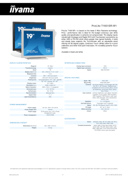
- Aug. 20, 1_940.
I
w. B. sHEAR
2,212,132
METHOD 0F AND APPARATUS FOR FORMING CABLES
Filed Nov. 30, 1957
.Q
QN
2 sheets-sheet '1
QQ
sì
In.
O
wfuSvl
.0 a o
mwo0.`
MK hk
INVENTOR
»f 8. SHEÁR
ATTORNEY
Aug. 2o, 1940.
'
w_ B, SHEAR
2,212,132
METHOD OF AND APPARATUS FOR FORMING CABLES
Filed Nov. 30,"1957
44 '
_
`
2 sheets-sheet 2
/2
A I‘TORNEY
2,212,132
~`Patented Aug. 20, 1940
VPATENT >orricle: y
Y UNITED STATES
2,212,132
METHOD' orV AND APPARATUS Foa
FORMING ` CABLES
Walter B. Shear, Newark, N. J., assignor to
Western _Electric Company, Incorporated, New .
York, N. Y., a. corporation of New York
Application November 30, 1937, Serial No. 177,319
(Cl. 57-138)
1,8 Claims.
relationship with a. stranding machine for re
A This invention- relates to a. method of and
ceiving the cable therefrom. Suitable end plates
I4 and I5 and a top plate I6 are secured tothe
apparatus for forming cables and more particu
larly to a method of and apparatus for com
I side walls -|I and I2 to complete the housing.
At one end of the housing (the right hand view 5
pressing covered electrical cables into predeter
5
mined shapes.
.
in Fig-1) are bearings I1 removably positioned
in the side .walls || and |2 for rotatably sup
porting the ends of sprocket shafts I8 and I9
(Fig. 2). The lower sprocket shaft I9 has keyed
_
In the communications art, reference being
made especially to switchboard assemblies, the
increase ‘in operators’ positions and the use of
different types of ,apparatus has created the
to an end thereof a gear 20 intermeshing with a l0
10 necessity in some cases for switchboard cables
being not only smaller in `size with the same
number or more conductors but' of different
gear 2|, which is keyed to the outer end of the
shaft I8, for operatively connecting the shafts
I8 and I9 to drive them in opposite-directions.
The gear 20 is driven by means of a sprocket
cross-sectional contours.
An object of the -present invention is- to pro
15 vide a more efficient method of and apparatus
for compressing and forming electrical cables
of various sizes and cross-sections.
`not shown. Upon the shafts I8 and |9 are flxedly
mounted sprocket-wheels 25 and 26 respectively,
the sprocket wheels of one shaft'being spaced
and disposed in general alignment with> the
,.
With such and other objects in view, one em
bodiment of the invention contemplates an ap
paratus, by the aid of which the method may be
20 practiced for forming electrical cables by mov
sprocket wheels of the other shaft. At the 20
opposite end of- the frame I0 another pair of
sprocket shafts 28 and 29 having sets of sprocket
wheels 30 and 3| mounted thereupon in exactly
ing -a cable core longitudinally through a- com
pressing means having driven diametrically op
posed endless chains of intermeshing overlapping
25
the same manner as those shown in Fig. 2 have
their ends journalled in. bearings disposed „in“ 25
movable bearing blocks 3| so that the shafts 28
die blocks travelling in a guided continuous arc
for cooperatively compressing the core into the
_and y29 with their respective sprocket wheels may
cross-section desired, the chains being supported
internally upon independently moving roller
chains and each die block being adjustable trans
versely to selectively position differently sized
30 cable channels in general alignment with the
path of movement of the cable core.
'
Other objects and advantages will appear from
be moved relative to their associated shafts I8
and I9 respectively. This movement or adjust- '
ment is" brought about by the aid of adjusting 30
-
screws
33.
_
.
A
Upon the sprocket wheels 25 and 3| is mounted
" .an endless chain 35 and a. similar endless chain
the following detailed description when cón
sidered in conjunction with the accompanying
35
_
wheel 22 connected to a suitable power means 15
36 being mounted upon the sprocket wheels 28
`and 3|. These endless chains are identical in
construction, ,they’having a plurality of die sup
,
'
»
` porting elements 38 extending parallel to the
Fig. 1 is a side- elevational view of lthe appara- „ sprocket shafts and mounted upon chain links
drawings, in which
ltus, portions thereof being shown in section;
Fig. 2 is a vertical sectional view taken along
the line 2-2 of Fig. l;
4vO
Fig. 3 „is an' enlarged front
'
elevational` view
of
one form of die block;
Fig. 4 is an enlarged front elevational view of
another form of die block;
“
‘ _di
Fig. 5 is an enlarged end elevational view taken
4.5 along the line 5--5 of Fig. l, and
Fig. 6 is an enlarged fragmentary view of the
die block shown in Fig. 3.Í ‘
Referring now to the drawings which illustrate
the apparatus by means of which the method
may be practiced, numeral ||| indicates in general
5
- a housing formed
of spaced vertically projecting
side walls || and I2 mounted upon base plates
I3,A the latter being arranged to be secured _to a
suitable support for positioning the apparatus in
55
39, the latter being positioned to be engaged by
the sprocket wheels. The die supports 38 have 40
reduced portions 40 which project inwardly and
are arranged to be engaged by rollers 4| of roller
chains 42.- The outer surface‘of each of the die
supports 3B has a dovetail slot 43 therein for re
movably receiving a corresponding element of a 45
die block 44. The dovetail connection between
each die block 44 and its support 38 is of course
merely one form of connection which may be used
between these elements permitting relative move
ment thereof for the purpose hereinafter de`- 50
scribed.
^
f
-
,
A
The roller chains 42 for each set of endless
chains 35 and 36 extend around rollers 46 as
illustrated in Figs. l and 2. The’rollers 4| of
these roller chains pass between the die supports 55
_
2
2,212,132
n' of the endless chains 35 and as and fixed,
guides 41 andf48.
The guides 41 and 48 are
_rigidly secured to embossed portions 4_9 and 50
of the side walls II and I2 and have roller en
gaging surfaces 52 formed with predetermined
The cable to be formed is indicated at 16 and
may be received directly from a stranding ma
chine and directed to dies 1 I ‘and 12 in a die hold
er 13. The dies 1I and 12 are removably'secured
in the die holder 13 and may be replaced by dies
arcs to cause the die blocks, through the aid of ' having selected apertures most suitable for the
the roller chains 42, to gradually move into form
ing position and gradually' move'out of such posi
tion without causing -harm to the cable being
10 formed. Resiliently supported bars 53 positioned
one _in engagement with each set of links 39 ofA
Ythe upper endless chain 35 support the upper
portion of the chain' while it is passing from the
sprocket wheels 25 tothe sprocket wheels 30. ‘
'I'he supports for the bars l53 consist of down
wardly projecting elements 54 of circular cross
section (only one being shown, see Fig. l) "slid
ably disposed in ‘spaced apertures in the em
bossed portion 49 and having shoulders which
20 rest upon -springs 55 positioned in the apertures.
type of cable being formed. Invforming- cables
withcircular cross-sections using the forms of
dies illustrated in Fig's. 2 and 3 it is desirable to
preform the cable with an oval cross-sectional
contour as illustrated in Fig.- 5. 'I'his may be
accomplished by placinga die 12 with an oval ap
erture 14 in the die holder 13 for preforming the
cable. The die holder 13 with its dies 1I`and 12
is rigidly secured to a removable cover plate 15
so that by removing the cover plate, dies of any
suitable type maybe inserted in place. At the
opposite end of the frame a cable guide '16 is se
cured to a removable cover plate 11, the latter
being secured in place by latches 18. The cable 20
Referring now to Fig. 3 one set of intermesh- A guide 16 and the dies 1I and 12 determine the
ing forming dies having sections 56 and 51 is i1
lustrated, each section having a> plurality oil
path of the cable ‘through the apparatus, this
path extending between the endless chains 35
‘ cable forming cavities varying in size to accom
25 modate cables having varying f numbers of _ and 36 to cause the die sections carried thereby
to act upon the cable as it is advanced through 25
strands. The cavities in the die section 56 are
formed of parallel grooves 58, rather deeply cut,
30
in the upper surface thereof, the grooves vary
ing in size and the inner extremities being semi
circular in contour. The lower surface of the
die section 51 is machined to form projecting die
segments 59 variable in size to slidably enter the
grooves 58 of the die section 56 and having con
caved"semi-clrcular lower surfaces, cooperating
35 with
the semi-circular portions of the grooves 58
to form circular die cavities. In general align
ment with each of the grooves 58 of the sec
tion 56-are disposed latch receiving recesses 68.
In the same arrangement latch receiving re
40 cesses 6I> are disposed in the die section 51.> The
purpose of these recesses is to properly position
_the die sections 56 and 51 relative toì theirire
spective supports 38, this being accomplished by
the aid of latches 62 pivotally carried by the sup- '
45 ports 38 andiurged into the desired recesses by
‘means of springs not shown. With this construc
tion the die sections may be adjusted to position
any selecteddie cavity in general alignment with
the path of the moving : cable, which 'is to be
50 formed, -or the die sections may be removed en
tirely andanother form of die maybe used as,
for example, that shown in Fig. 4.
the apparatus.
\
To' condition the apparatus for operation the
end plate 11 may be removed as well as acover
plate 80, removably disposed in the side wall II,
so that the operator may gain access to the end
30
-less chains 35 and 36. for assembling the desired
die sections on the chains. A number of the die
sections may be assembled While 4the endless
chains are at one position and by causing inter
35
mittent movement of the chains all the die sec
tions may be in the desired locations and in place.
The cable is then threaded through the apparatus
and the plates 11 and 80 again secured in their
- proper positions.
'I‘he operation of the apparatus is as follows: 40
Rotation is imparted to the sprocket wheel 22
which rotates the gear 20 _with the shaft I9 in a '
clockwise direction, viewing Fig. 1. The rotation
of the shaft I9 in this direction causes the up
per portion of the endless chain 36 with its die 45
sections to move to the right with the cable 10.
The upper chain 35 with its die section is moved
in just the opposite direction due to the opera
tive connection'of the gear 2i with the' gear 20
causing a lower portion of the chain 35 to move 50
in unison with the upper portion of the chainy
36. This unitary movement of the chains 35~ and
The form of die 'shownin Fig. 4 is for forming ' 36 causeseach diev section carried by the chain
flat-sided cables and is> composed of die sections 36 to register with its associatedl die section car-.
55 63 and 64 having their respective latch receiv
ried by the upper chain 35. Before the die sec 55
ing recesses 65 and 66 respectively. The die cav
tions -are moved into engagement with the
ities in this form have flat forming walls 6.1 and 68 strands forming the cable 10 they have arrived at
as compared to the semi-circular forming-.walls a position where they will engage the rollers 4I
of the die‘cavities shown in Fig. 3.. Thedie cavi -,of the roller chains 48 rto be guided through arcs
60 ties in both forms have their centers in general"
causing gradual movement of the die sections
alignment so that the apparatus may be condi
toward each other and away from each other astioned to receive larger or smaller cables merely . they move into and out of forming position. 'I'his
by adjustment of the die sections without re _ gradual movement of thev die sections toward the
quiring further adjustment in the apparatus to cable to compress it and away from the cable to
compensate for the variation in size of the cable> free the die sections therefrom is brought about
being formed. The form of die sections shown in by the guide plates 41 and 48. The rollers 4I of
Fig. 2 issomewhat similar to that shown in Fig. 3v the roller chain 42 provide substantially friction
but with larger die cavities to accommodate larger less associations between the stationary guides 41
cables than those required for the cavities shown and 46 and their respective chains 35 and 36.
70 in Fig. 3.' The overall width of the die sections is `The rollers 4I are smaller in diameter than the`
approximately half the width of the die supports ‘ width of the die supports 88 so4 that at all times
. 38 of the endless chains 35 and 36 allowing sufli
cient space for the lateral movement of the ~dies
to position the selected die cavity in alignment
75 with the cable being formed. .
more than one roller will be in engagement with
each of its supports during the forming operation
to prevent rocking of the supports and the die
sections carried thereby. '
75
23>
2,212,132
It will be observed, by viewing Fig.- 1, that the
sprocket -wheels 30 and 3l are positioned away
4. In a cable forming apparatus, means for
advancing a cable to 'be formed, and means
movable with the cable in a continuous arcuate
from the advancing cable suflicient distances to
path for applying increasing pressure thereto to
swing the die sections from the outerlines to the
inner lines without the forward edges of the die
compress the cable.
cavities touching the cable. The die sections are
advancing a cable to be formed,
movable with the cable in a continuous arcuate
moved at a faster rate of speed around their
5. In a cable forming
sprocket wheels than they travel between their path for applying increasing pressure thereto for
10
-sprocket wheels and if the forward edges of the -forming the cable with ñat sides.
die cavitiesl of the die sections 1n position A
should engage the cable, that portion of the cable
between the die sections at position A and the die
sections at position B would be damaged and a
portion if not all of the insulation stripped there
6. In a cable forming apparatus, intermeshing
forming elements having arcuate shaped cable
receiving cavities, means for moving said ele
ments substantially perpendicularly toward- each
other for forming a cable, and means in advance
from. Therefore, the die sections are moved into , of said forming elements for preforming a cable
position B before they are moved into engage
to a thickness less` than the diameter of the
ment with the cable. Furthermore, there is no cavities of said elements.> >
relative movement of the die sections in each . 7. In a cable forming apparatus, diametrically
group from position B to position C inclusive opposed endless chains, supports carried by said 20
and even at these positions the surfaces forming chains, sets of cable forming dies having cavities
the die cavities are free from the cable.
varying in size for different sized cables to be
With the form of die- section illustrated in formed, portions of said dies being movably
Figs. 2 and 3, the cable is preformed by passing carried by said supports of one of said chains 25
through a die 'l2 having a substantially oval and the associated portions of said dies being
aperture so that when the cable passes between
the die sections carried by the chains 35 and 36,
movably carried by said supports of the ‘other
chain,- means for imparting movement to said
the conductors forming the cable will not become
chains` to cause the adjacent portions to move
pinched or damaged betweenvthe die sections
with the cable
as might occur if the conductors forming the
80 cable werev directed through the forming dies of
the chains in a rather loose manner. By viewing
to be formed, and means for ~
securing each of said die sections in any selected
30
position relative to the path of movement to the
Fig. 6 it will ,be observedA that in forming round cable.
8. A method of forming cables comprising ad
-cables the curvature of the cable at the point vancing a cable, applying a continuously and 35
of highest pressure will not be exactly symmetri- e gradually increasing pressure. to the cable during
35 cal but will be somewhat flattened, so that when the advancement thereof to compress the cable,
the cable is released or freed from the forming and subsequently decreasing the pressure gradu
dies and allowed to expand it will assume almost
9. A method of forming cables comprising ad
a perfect circular cross-section.
.
_
The embodiment of the invention herein dis
vancing a cable, preforming the cable to cause 40
closed is illustrative only and may be departed the cable to substantially flatten it, applying a
from and modified without departing from the gradually increasing pressure to the cable at its
spirit and scope of the invention as» pointed out greatest width to compress the cable, and de
in and limited only by the- appended claims.
creasing the pressure gradually after a predeter
45
mined pressure has been applied.
W'hat is claimed is:
1. In a cable forming apparatus, diametrically
10. A method of forming cables comprising ad
opposed endless chains, means for imparting vancing a cable, and applying a pressure gradu
movement to said chains to cause their adjacent ally through an arcuate path to the cable during
portions to move in the direction of a cable being the advancement of thevcable to compress the
50
ally.
'
`
.
formed, intermeshing die elements having cable -
cable.
receiving cavities \of varying sizes, and means
carried by said chains for movably supporting
.
'
I
` 11. A method of forming cables comprising
advancing a cable, and applying a gradually
said die elements to selectively position the de
increasing and decreasing pressure through an
sired cavities in operating positions.
arcuate path during the advancing of the cable
2. In a cable forming apparatus, diametrically tov compress the cable.
opposed endless chains, means for imparting 12. In a cable forming apparatus, forming ele
movement to said chains to cause their adjacent ments having cable engagingsurfaces, means for
portions to >move in the direction of a cable to moving said forming elements with a cable being
be formed, intermeshing die blocks. carried
formed, and means to cause movement of the -
said chains, and means for guiding said chains
to cause movement of the die blocks of each
elements to cause the cable engaging surfaces
chain toward and away from'the cable without
moving the die blocks of each chain relative to
each other to compress the cable.
_
»s
3. In a cable forming apparatus, diametrically '
65
opposed endless chains, means for imparting
movement to said chains to cause their adjacent
portions to move in the direction of a cable to
be formed, intermeshing die blocks carried by
said -chains, means for guiding said chains
to cause said die blocks to move toward
70 the cable without relative movement >to each
lother until- a maximum pressure has -been
applied to the cable, and separate substantially
frictionless means disposed between said guiding
75
means and said chains and moved by said chains. »
to form an arc extending from a position out
of engagement with the cable, through a 4maxi
mum pressure position and to a position out of
engagement with the cable.
13. In a cable forming apparatus, forming
elementsL means f_or moving said forming ele
ments with- the cables being formed, and means -A
for causing movement of a group of said elements
through continuous arcs into, during and out of 70
forming positions'.
.
14. In a cable forming apparatus, diametrically
opposed Vendless chains, die blocks carried by
the chains, means for imparting movement to
the chains to cause their -adjacent portions to
move the elements carried thereby inthe direc
4
2,212,132
-tion of a cable to be formed _and through arcs
17. In a cablei'orming apparatus, diametrically
to compress the cable, and means to guide‘the `~ opposed chains,- cable forming elements having a
'elements into the arcs prior to their engagement `plurality of cable forming portions variable in
with the cable.
‘
.
contour for various types of cables, supports for
15,. In a cable forming apparatus, diametrically the elements carried by the chains, means for
opposed endless chains, die blocks carried by the each support to adjustably locate its respective"`
chains,- means for imparting movement to the
chains to cause their adjacent portions to move
the elements carried thereby in the direction of a
element toposition a desired forming portion
thereof to engagev a cable to be compressed, and
means to move the chains to move the elements
10 -cable to be formed and through arcs to compress to compress the cable.
,
10
the- cable, and means to'guide the elements into 18. In a cable forming apparatus, diametrically
thefarcs prior _t'o their engagement with the cable
and move the elements free of `the cable prior
to their movement out of the arcs.
opposed chains, cable forming elements, sup
ports for the elements carried by the chains, a
guide for each chain having an arcuate surface,
means to move the chains, and a series of rollers
opposed chains,~ cable forming elements having for each chaixrmovable therewith between the
a plurality oi'cable forming portions, supports supports and the guides to cause movement o!
for 'the elements/carried by the chains, meansl the elements continuously through arcs to com
for each support to adjustably locate its respec
press ythe cable from positions free of the cable
20 tive element to position a desired forming por
through maximum pressure positions to positions 2°
tion thereof ,to engage a cable to be compressed, free oi' the cable.
and means to _move the chains to move the
WALTER B. SHEAR.
15
16. In a cable forming apparatus, diametrically
elements to compress the cable.


© Copyright 2026