
Document 440073
Sept. 3, 194%“
I... QUILLIAM
2,213,409
TRAFFIC CONTROL SYSTEM
Filed May '7, 1936
2 Sheets-Sheet 1
VEHKZLE
DETECTOR.
516NAL
A8
(2gb
A STREET
\lEHlCLE
DETECTOQ
BSTQEET.
t
28‘ h
Fig, 1
VEHICLE
DETECTOR
ti
:15
up
—-———I&
TO COnJrroL
‘q
5%
4/50""
51
50
V/
V/
\\
_\
~\ /.
‘
.\\~\[h?:
“
X I’ --’ '
Fig., '21
§—<—\
Cyde——>*:I
i
{:IEQEEN
ASTQEET i1
IEIYELLOWI]
RED‘
8 SWEET
:{
|
‘:GQEEN 1:]
Q
HIIYELLOW 1:1‘
MENTOR
{III RED l :2‘
LESLIE QUILLIAM
1
By
HQ,“
Fig" 4‘
kb? ‘
$2’
2 ,(v_
ATTORNEY
Sept. 3, 1940.
2,213,4439
|_. QUILLIAM
TRAFFIC CONTROL SYSTEM
Filéd Ma}; '7, 1936
2 Sheets-Sheet 2‘
LESUEQUILLIAM.
3Y0;
fATTORNEY
'
2,213,409
Patenteclisept. 3, 1940
STATES
@Fiii?id
g?llgfliiil
Leslie Quilllam, Stretched, England, ssc'lgnor
‘Co.2 Inco po==
sated, houisvilie, lliy.9 a col’ ration
Nmhotl do ‘United dilated Si
Application
"6’, N36, Scale-l ‘No.
53 illaimo°
My invention relates to tra?lcwcontrol systems
and has particular relation to those used at ma»
jor highway intersections.
'
Under ordinary circumstances, tsaiidc=control
mom.
.
. a further
motor-driven,
object camlaconti‘olled
oi my inventioncontact
is
systems are arranged to provide a fixed signs -=
- -echariism for controlling the signal lights,
timing that will best accommodate the traiilc
conditions encountered at the highway intersecé»
which mechanism will determine the minimum
it
or has
initial
been
timecalled
of display
to a lane.
oi the “go” signal
tions where they are intended to he utilized. ‘ it
has been. observed, however, that at certain pe=
'a.) (3 riods'oi the day the trafdc along one lane of an in~
tersecti'on is comparatively heavy while the traf?c
along an intersecting lane is comparatively light.
’
A still further object o1 my invention is to pro=
vide a. non=resetta7ole timing mechanism adapted 103
to be operated
vehicles moving along a lane
to me out the “go” signal from being transi’ei‘sed
at other periods of the doy the trafdc along the
ly heavy, while the
trafflcalong the "
lane is comparatively
light. During the remaining periods, the traffic
to
continued
an intersecting
to display
lanefor
until
a predetermineo
the “go” si altime,
and
until the said timing mechanism has re T15
stored to normal from a previous vehicle opera
along both lanes is substantially of equal density. ' tion.
It is accordingly an object oi’ my invention to
More concisely stated, it is the object of my
invention to provide a vehicle-operated, traffic
application to a highway intersection at
v hich the trafdc along one lane is heavy as com=
pared with the traflic along an intersecting lane
at certain periods while the converse is true at
certain other periods.
I
>
a further object of my invention is to provide
a tra?lc=control system that has particulas' ap=
plicatlon to an mtersection wherein the ratio of
‘the density of the traffic in one direction to the
density of the trafdc in an intersecting direction
30 varies considerably from time to time.
Another object of ‘my invention is to provide
apparatus or" “the type that is responsive to the
condition of traffic along a plurality of intersect=
ing lanes; the apparatus being adapted to regu
late the operation or“ a traffic signaling device
that normally operates to cause the “go” signal
to remain on thethcroughfare on which the ve=
hicles were last operating.
Another object of my invention is to provide
a vehicle actuated tra?lo-oontrol apparatus
adapted to be utilized at the intersection of a
plurality of lanes; the apparatus being of such
structure that a traffic signalling device will be
controlled by a vehicle moving along one lane to
indicate a “go" signal for that particular lane
with a "stop” signal for all intersecting lanes,
which signals will continue to be displayed until
a vehicle approaches on one of the intersecting
50
lanes.
~
Another object of my invention is to provide
a motor-driven, cam-controlled contact mecha
nism for controlling the tra?c signal indications,
which mechanism may be adjusted to provide
55 any desired sequence of signal indications with
control apparatus in which the vehicles moving g
along a lane, having a "go” signal shall cause the
"go” signal to be extended a definite time for
each vehicle o‘ eration, such that the time of the
"go” signal for a following vehicle will not be=
come effective until the timing for the preceding 25
vehicle has elapsed...
A further object of my invention is to ‘provide
an extension control for the display of the “go”
signal which, under continuous vehicle operation, ,
shall regard the vehicles as moving in groups,
and provide ‘out a single extension for each of
said groups.
v
Another object of my invention is to provide
an extension control for the display of the “go”
signal that will not be responsive to bring about
a further extension of the “g0” signal by a fol
lowing vehicle, unless such vehicle approaches a
predetermined time after the' extension control
commenced its operation for a previous vehicle.
A. still further object of my invention is to pros
vide a maximum timing-mechanism that will
begin its operation at the initial establishment
of the "go” signal to a lane for permitting trans
for of the “go” signal to an intersecting lane,
when a vehicle approaches on the intersectingv
lane at anytime after the maximum timing '
mechanism has completed its operation.
A still further object of my invention is to
provide apparatus to be operated by a vehicle
approaching on a "stop” signal, and which will, 59
remain operated until the “go” signal is trans=~‘ '
ferred to that vehicle.
One of the fundamental objects of my inven»
tion is to provide a system in which the opera
tion of the motor controlling the cam-operated, 55
2
2,213,409
contact-mechanism governing the display of the
signal lights is “stopped” or'“arrested” in order
to maintain the “go” signal displayed.
the various connecting wires to the control mech
Another object of my invention is to provide
a vehicle-operated, tra?ic-control apparatus
having a plurality of stages or conditions of op
intersection, however, it will be obvious to those
skilled in the art that my invention may be
utilized at an intersection involving a greater,
eration; the particular conditions of operation
to be utilized at various times dependent upon
the condition of the traffic along the lanes form
sist in the understanding of my invention, the
intersecting lanes have been designated as "A
.
10 ing the intersection.
According to my invention, I provide a traffic
control system comprising a plurality of street
devices located along the lanes of a particular
intersection, and adapted to be controlled by ve
tem of relays, motor-driven, cam-operated con‘
tact mechanisms and a signaling device.
Under normal circumstances the signaling de
vice displays a "go” signal long the lane on which
vehicles were last operating with a stop signal dis
played to all other lanes. A vehicle approach
ditions according to the particular requirements
of the intersection to be signaled. Hereinafter,
in the description, only the vehicle detectors l8
and 28 will be speci?cally dealt with.
ing on a lane having a “stop” signal causes actu
ation of a vehicle detector, which in turn responds
by co-acting with a system of relays to cause the
For the construction of one form of vehicle
detector used with my invention reference is
made to Fig. 2. This particular form of detector
“go” signal to be displayed to the lane onwhich
illustrates’the type which comprises a yieldable
tube enclosing electric contacts and arranged be
tween rigid side bars having pro?led or inclined
faces to protect the tube. This form of vehicle
hereinafter be referred to as "vehicle-detectors.”
The vehicle detectors are associated with ‘a sys
the vehicle approaches and a "stop” signal to all
other lanes. A vehicle approaching the inter
section on the lane having the “go" signal causes
actuation of a vehicle detector which in turn re
sponds by co-acting with the system of relays to
cause the "go” signal to be extended for a de?nite
time interval. A vehicle following a predeter
mined time thereafter and causing actuation of
the vehicle detector will register its presence, and
thereby effect a further extension of the “go”
signal for a predetermined time after the exten
sion interval of the previous vehicle has elapsed.
The "go” signal thus controlled by the vehicles
persists until a vehicle moving along an intersect
ing highway causes actuation of its vehicle de
tector whereupon the "go” signal will be immedi
_ ately transferred to the approaching vehicle when
vehicles cease to move on the highway having
the right-of-way or, in the case of continued
vehicle operation, of the “go” signal on the street
having the right-of-way, when the maximum
time control mechanism operates.
50
55
or lesser number of lanes than indicated. To as
Street” and “B Street.” In “A Street,” a vehicle 10
detector I8 is indicated to the left, while a sec
ond vehicle detector connected in multiple there
with is indicated at the right. In “B Street,”
a vehicle detector 28 is indicated at the lower
end, while a second detector connected in mul 15
tiple therewith is indicated at the upper end.
It will also be obvious to those skilled in the
art, that any number of vehicle detectors may be
connected in multiple to accommodate other con
hicles moving along the lanes, which devices will
20’
anism indicated. For simplicity, my invention
has been shown as applied to a usual four-lane
detector is narrow, and has a contact mech
anism, which mechanism rests on resilient mate
rial so that when the tube is depressed, the side
bars substantially take the load of the vehicle.
The mechanism of the ‘vehicle-detector com
prises an upper, ?exible contact-strip 56, which
strip is located ‘in a channel-section resilient
strip 55 of‘ insulating material. The resilient
strip 55 rests on a lower ?exible contact strip 58
and has its base formed with a series of holes 40
for the passage of contact points 51 carried by
the contact strip 58.
The lower contact strip
58 rests on a cushion comprising a perforated
thick rubber strip 59. A resilient cord 513 is
seated in the channel of member 55 above the 45
upper contact strip 56. All these parts are en
closed in a rubber tube. 53, which tube is sealed
at both ends to exclude moisture and dirt. At
one end of the tube, the contact strips 56 and
If two vehicles should appear at the intersec
51 are brought into a junction box so that elec
tion, each along separate lanes, the "go” signal
will be given to the vehicle ?rst arriving at the
trical connections may be made to the detector.
The contact mechanism encased in the rubber
intersection whereupon it will be transferred to
the waiting vehicle at the earliest opportunity.
tube 53 rests in a suitable recess fashioned in a
In further describing my invention reference
is made ‘to the accompanying drawings, in
which
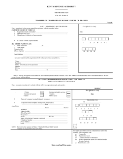
Figure l is a plan view of an intersection show
ing the relative location of the signal and the
60 vehicle detectors in the various lanes comprising
the intersection.
Fig. 2 is a sectional view in perspective of one
> of the vehicle detectors.
_ Fig. 3 is a schematic wiring diagram showing
50
rigid supporting base 50 and is covered by a rub
ber, tire-like cover 52. The cover 52 is prefer
ably constructed according to principles employed
in the construction of automobile tires, and is
secured in place by side bars 50a and 50b, which
side bars are secured to the rigid base 50 by ?at
head screws 5|.
Pressure of a vehicle wheel 60
is transmitted to the strip 56 by cord 54, and, if
the pressure is great, the cord 54, strip 56 and
channel member 55 move downwardly as a unit
owing to the yielding strip 59, so that the wheel
the system of electrical connections employed to rests on the side bars 50a and 50b thereby pre 65
bring about the various objects of my invention.‘ venting any damage to the cover 52. In the
Fig. 4 is a graphical representation showing downward movement of the cord 54, the upper
the particular color sequence employed in this contact strip 56 is brought into engagement with
disclosure of my invention.
one or more of the contact points 51 by reason of
70 Referring to Figure 1, it will be noted that my the resiliency of' the channel member 55. The
invention comprises a vehicle-detector positioned engagement of the contact member 56 and con
in each lane and arranged to be actuated by ve
tact points 51 completes an electrical circuit,
hicles approaching the intersection. At the in
which circuit is utilized in the operation of my
tersection, a conventional suspension-type color
invention. When it is necessary to provide a ve
75 light signal is diagrammatically represented with hicle-detector that will operate the signal mech 75
2,218,409
3
anism only upon the approach of a vehicle, two
operation, the operating coil 83 of relay I is
or the contact mechanisms sealed in the rubber
tube 53 are arranged parallel in a single rigid base
energized, bringing the armature 38 into en
gagement with contact 38a. The operation of
armature 38 completes a stick circuit for relay
50, and provided with separate covers 52. With
this arrangement, a relay system is employed.
that will cause operation of the signal when the
detectors are successively operated in one direc
tion and not in the other.
I
,
While I have shown and described one type
10 of a detector, it is to be understood that other
types may also be employed in the control of my
invention. Such other types may comprise a trol
ley wheel and trolley contactor of an electric rail
way‘, electrostatic, magnetic inductor, photo
15 electric cell, sound or microphonic, and I do not
1, and a retaining circuit for the motor D2 of
mechanism H, tending from BX through contact
1a, contact arm 2‘, wire 24, armature 38, contact
38a, wire 2Ib, wire 2M, contactv 8a, contact arm
8, wire 22 and motor D2 to CX. With motor D2
energized, the cams are rotated in the direc—
tlon indicated by the arrow appearing in cam C9.
Shortly after the cam 68 begins its rotation,
contact arm 8 disengages contact. 8a, and the
arm 8 immediately engages contact 81), which
engagement establishes running circuit, for the
desire to be limited to the~use oi the specific type
motor D2. After the running circuit is estab
of detector described.
For a complete understanding of the electrical
lished, the cam 01 causes the contact arm 1 to
connections employed to bring aboutithe various
circuit for relay I permitting the latter to re
store to normal. The cam C1 is also adjustable 20
so that it may be set to operate contact arm 1
to open the stick circuit for relay I at any time
after the operation of contact arm 8. This fea
20 objects of my invention, reference is made to
Fig. 3. The central vertical dotted line of Fig. 3
is provided to distinguish the control relays and
signal lights for A street from those for B street.
The dotted rectangles are provided to indicate
25 the mechanism included in each relay so out
lined.
The
’
motor-driven,
cam-operated
contact
mechanism T represents a conventional form of
traffic-signal timer having cams that may be
8% adjusted to provide any'color sequence desired,
and which may be further adjusted to provide
any timing interval as may be required. As
illustrated, the mechanism T has its cams ar
ranged to provide a color sequence of indica
tions graphically shown in Fig. 4. To assist in
the understanding of my invention, it will be
assumed that the mechanism T, when placed
into continuous operation, will require 26 sec
disengage contact ‘la, thereby opening the stick
ture is provided since following vehicles operat
ing detector l8, immediately after the timing 25
mechanism H commences its operation, need not
set-up a control to bring about a repeat opera
tion of mechanism H. Thus the cam Cl is ad
justed to determine the period for repeat op
erations of mechanism 1-! according to the par 30
ticular requirements of the intersection. Inci
dent to the operation of motor D2, and before
operation of the contact arm 8, cam C9 caused its
contact arm 9 to disengage contact 91!, thereby
opening the circuit via wires 26 and ‘25 con 85
necting motor Di of mechanism ‘I’. With the
running circuit for motor D2 held closed by cam
C8, the motor will continue to operate until the
onds to complete one cycle of operation. With
notch of cam C8 permits the contact arm 8 to
this adjustment the green .interval for each
street is set at 10 seconds and the yellow in
tervals at 3 seconds each. With the disconnect
disengage contact 8b, which is one revolution of
- switches R and S, in the position indicated, the
mechanism T is normally held at rest at either
points a or b1 as indicated in Fig. £1...
Thus it
will be apparent that when the mechanism T is
placed in operation, say, for instance from point
a, the green on A street is immediately extin
guished and a yellow displayed to both streets
50 A and B with the red continued for three sec
onds on street B. After three seconds both the
yellow and red will be extinguished and a green
displayed to B street and a red displayed to A
street. After the transfer, the mechanism T will
55 continue to operate for 10 seconds, whereupon it
will stop its operation at point in to maintain
the last mentioned signal conditions until again
placed into operation in response to an ap
proaching vehicle on A street. When again
til placed into operation, the same sequence of in
dications will be presented with the exception
that green will be transferred to A street and
red to B street whereupon the mechanism will be
stopped id seconds later when the point a of
65 Fig. 4 is reached.
The motor-driven vtiming-mechanisms H and‘.
0 are identical in construction and operation.
Accordingly only the operation of the timing
mechanism H will be described. Normally the
70 timing mechanism H is at rest, and assumes the
condition indicated in Fig. 3. When the con
necting wire 2la is potentialized from the ve
hicle-detector l8, current ?ows through contact
8a., contact arm 8, wire 22, through the motor
75 D2 to the return‘of the line (32!. Instant to this
the cam Ct.
The speed of the cams oi the
timing mechanism H is adjustable, and, for pur
poses of this description, it will be assumed that
they are adjusted to complete one revolution in
5 seconds. The timing mechanism H is not of
the resettable type, and therefore must com
plete one cycle of operation before it can again
be operated. In this respect it will be noted
that the interruption of the stick circuit for
relay I by cam Cl is an intermittent operation. 50
Therefore, a potentialization of wire Zia at any
time during the operation of the timing mech
anism H will cause the relay I‘ to be retained
operated until the contact 8 is restored into
engagement with the contact 80., whereupon the 56
starting circuit for motor D2 will be completed
from wire fill to cause a continued operation of
the motor D2.
Relays E, F, 1', J, M, N, P and Q are of the
quick-acting type, well known in the art, while 60
relays K and L are of the retarded pickup type.
Such a retardation may be accomplished by
many well known principles, such as a dash-pot
or escapement mec‘i'iansim. The relays K and
L are of, the type in which the contacts are re
86
stored to their normal condition immediately
upon de-energization of their operating coil.
The relays K and L are employed to control the
maximum time 'a “go" signal may be held from
a waiting vehicle. Noting in particular relay K 70
it will be seen that as long as current is ilowing
to the A street green signal lamp G, the coil S5
is energized. At the expiration of a predeter
mined period, say, 30 seconds, the armature 37
will engage contact 31a. In this respect it is 75
4
2,213,409
important to note that no further operation will
be effected unless the wire 36a was previously
place \' at positive potential through the opera
tion 0
armature 35 of relay Q.
As previously stated, mechanism T is assumed
to be adjusted to time a 10 second initial display
of the “go” signal to each street, while mecha
nisms H a'nd‘O are adjusted to time a 5 second
extension of the “go” signal. While these timings
10 have been speci?ed, it must be understood that
they may be set to any timing desired. Ordi
narily, the extent of the initial timing of mecha
nism T is determined by the time required to
move all vehicles through the intersection accu
15 mulated between the detector and intersection on
a “stop" signal, while the timing of the extension
controls H and O is determined by the time re
quired ‘for a vehicle to move from the detector
through the intersection on a~“go" signal. The
maximum timing of the “go" signal, by relays K
and L, is determined by the amount of tra?ic thatmay be permitted to accumulate on a “stop” sig
nal in any one lane, or the maximum delay which
should be imposed on a vehicle arriving on a
“stop” signal immediately after a signal transfer.
From the foregoing it will be apparent that
since my invention is responsive to tra?lc its op
eration will, of necessity, vary with diiferent trai
?c conditions and di?erent adjustments of the
30
controlling mechanisms. Therefore, having thus
circuit is completed from BX through armature
32, contact 32a, wire 33, wire 33a, armature 35,
contact 35a, wire 36, contact 2311, armature 23,
wire 21, contact arm l2, contact lZd, wire 28, con
tact 9a, contact arm 9, wire 25 to motor DI
thence to the return of the line OK. This en
ergization of the motor DI will cause its associate ,
cams to rotate in the direction indicated by the
arrow appearing on cam C5, whereupon the con
tact arm 6 will engage contact 6a to complete
a running circuit for motor Di through Wire 2511.
With the motor DI thus energized, the‘green of
A street will be extinguished and‘a 4-way amber
indication displayed for 3 seconds, whereupon the
green signal G on street B, and the red signal R
on A street will be displayed. As described here
inbefore, the motor DI ‘will continue to operate
for 10 seconds after this transfer occurs, to time
the initial display of the green signal to B street.
Incident to the display of the green signal G for
B street via wire l3, relays L and M were oper
ated via wires I3a and I3!) respectively. With
relay M operated its armatures 30 and 32 disen
gage contacts 30b and 32a respectively and the
armature 30 engages contact 30a. The disen 25
gagement‘of armature 32 from contact 32a opens
the stick circuit for relay Q and the starting cir
cuit for motor DI via wires as, as, 21, 2s and 25,
etc. Thus, when the motor DI advances its
cams to the position 1), indicated in Fig. 4, the 30
described the fundamental operation of my in
vention, I will now give speci?c illustrations of its
operation under various conditions of traffic and
contact arm 6 disengages the contact 6a and
opens the running circuit for the motor DI. If
adjustments.
B the signals will remain continuously in the
35
condition to which they were last operated.
Condition 2
Single vehicle approaching on A street:
ADJUSTMENT 1
Referring to Fig. 3, of the drawings, I will as
sume that disconnect switches R and S are posi
tioned so that wires 36?) and 3212 are connected
to wires 36a'and 32a respectively.
40
With these adjustments, the go signal will re
main on the street to which it is last actuated,
and, as shown in Fig. 3, the go signal is now on
no further vehicles operate on either streets A or
I shall nowassume that no vehicles have oper
ated on either street A or B, and the timer mech 40
anism T has advanced to the point 0. indicated in
Fig. 4, and that a vehicle now approaches on A
the A street. ’ Assuming that no vehicles have
street.
operated the vehicle-detectors for some time, the
The single vehicle approaching on A street and
engaging the vehicle-detector I'8, completes a cir-' 45
cuit from BX through the detector l8, contact
following illustrations outline the speci?c opera
tion of my invention under certain conditions of
I
\
trai?c. It will be understood, however, that
18a, wire i3, armature 20, contact 20a, wire 2i,
many other conditions of tra?ic may prevail
operating coil S3 of relay I to the return of the_
line CX. The resultant energization of operat
ing coil S3 raises armature 38 into engagement
with contact 38a, and establishes a stick circuit
for coil C3 from BX through contact la of timing
mechanism H, contact arm 1, wire 25, armature
38, contact 3811, wire 2|b, coil S3 to the return of ,
the line CX. With wire 2lb potentialized from 55
other than those speci?cally outlined. There
fore, the operation of my invention is not to be
regarded as applicable-only to the particular con
ditions provided hereinafter.
,
Condition 1
55
Single vehicle approaching on B street:
To further explain the operation, of my inven
tion, I shall assume that signal G of A street,
and signal R of B street, are displaying, and that
the motor driven mechanism T has advanced to
60 position a indicated in Fig. 4. As long as vehicles
do not approach on either street, the signals will
remain continuously in this condition.
A single vehicle approaching on B street, and
operating the vehicle-detector 28, will close a cir
65 cuit from BX through the detector 28, contact
BX as described, a circuit is also completed from ,
wire 2|b, through wire 2la, contact 8a, contact
arm 8, wire 22 to the motor D2 of timing mecha
nism H. With the motor D2 thus energized its
associated cams‘will revolve as hereinbefore de 60
scribed in the description of timing mechanism
H. During the revolving of cam C9, the contact
arm 9 is separated from its contact 90., thereby
preventing energization' of motor Di oi the
mechanism T via wires 36, 21, 26 and 25, even 65
28a, wire 29, armature 30 of relay M, contact 30b,
wire 3|, coil SIO of relay G to the return of the
line CX, thus operating ‘armatures 34 and 35 of
relay Q. When the armature 34 engages contact
70 34a, a stick circuit is completed from BX through
though a vehicle should approach on street B and
armature 32 of relay M, contact 32a, wire 33, ar
mature 34, contact 34a, wire 3|a, coil S10 to the
return of the line CX, thereby retaining the ar
matures 34 and 35 in their operated positions.
75 When the armature 35 engages contact 350, a
onds by a single vehicle on B street:
operate the vehicle-detector 28.
'
Condition 3
Single vehicle on A street followed within 5 sec
70
'
I shall now assume the condition of operation
set forth in Condition 2 with a vehicle approach
ing on B street while'the timing mechanism H is
in operation.
‘
75
5
2,218,409
The approaching vehicle on B street engaging
the vehicle detector 28 completes a circuit from
BX through the detector 28, contact 28a, wire
by merely constructing contacts 80-81) with a
29, armature 30, contact 30?), wire 3|, operating
coil SID of relay Q to’ CX, thus energizing coil
make before break feature. Thereafter the cam
C9 will function to separate contacts 9 and 9a
and prevent the energization of motor DI via
wire 25.
S l 0, and thereby raising armatures 34 and 35 into
It will be noted that if two or more vehicles
'engagement with their respective contacts 34a
operate the detector “3 during the operation of
and 35a. With the armatures raised, a stick cir~ ‘the timing ‘mechanism H, only a single repeat
cult is completed for relay Q via wires 33 and 3la. operation of the timing mechanism will be ef
10 Wire 26 is also potentialized via wires 33, 33a, 36 fected. Thus it may be observed that the vehi 10
and 21. It will be noted, however, that, since the - cles are divided into groups, so to speak, such
contacts 9 and 9a are disengaged, the wire 25 will that all vehicles moving in a single group auto
not be potentialized until the timing mechanism matically cause a further extension in the display
H is brought to rest, and the contacts 3, 9o per
of the go signal as soon as the timing of the
15 mitted to close. Thus the “call-on" relay Q re
previous group has elapsed.
15
mains operated to bring about a transfer of the
Condition ‘5
go signal to B street, as soon as timing mecha
nism H is restored to normal.
20
Vehicles continuously approaching on A street‘
'
Condition 4
'
for a de?nite time with a single vehicle waiting
’
Single vehicle on A street followed within 5
20
on B street:
_ I shall now assume the conditions set forth in
seconds by a second vehicle on A street and a
Condition 4 with vehicles continuously approach
single vehicle on B street:
ing on A street such that the timing mechanism
H is held in continuous operation until the go sig
nal is transferred to 3 street. In this respect it 25
_
I shall now assume the conditions‘set forth in
25 Condition 3 wherein a following vehicle engages
the vehicle-detector l8 while the timing mecha
nism H is in operation. It will be remembered
that the cam Cl momentarily interrupts the stick
circuit of relay I shortly after the timing mech
Sit anism H is placed into operation. Therefore, the
relay I has been restored to normal from the
previous vehicle operation.
When the following vehicle on A. street en
gages the vehicle detector It a circuit is com
35 pleted from BX, through the detector l8, contact
lBa, wire l9, armature 20, contact 2%, wire 2i,
coil S3 to the return of the line CK, thus energiz
ing coil S3, and raising armature 38 into engagee
will be noted that as soon as the cam C2 of the
mechanism T brought the contact arm 2 into
engagement with the contact 2a. to establish the
go signal on street A, a circuit was completed
through wires Ida, Mb, Me, operating coil S4 of 30
relay J to the return of the line OK. The relay
J maybe termed a “selector” relay in that it de-_
termines whether the impulse from the vehicle
detector i8 is to be transmitted to the “call on”
control relay E or the “time extension" relays I’ 35
and H; Incident to the operation of relay J the.
operating coil 85 of relay K is energized via wire
Mb. Thus ‘after a predetermined time, say 30
seconds, the armature 31 of relay K engages its
front contact 31a. As assumed in Condition 4,
ment with its contact 38a. With armature 38
raised, a stick circuit is established for relay I via
contact ‘Ia and wire 24. Wire 2|a is also poten
the wire 36 is being held potentialized through
tialized, as described for the previous operation
of the timing mechanism H, but, since the timing
an operation of relay Q in response to a vehicle
approaching on the B street red signal. Thus, as
mechanism H is now in operation, the contact 8a
is disengaged by the contact arm 5, therefore no
further operation will be effected until the cam
C8 permits the contact arm 8 to engage the con
soon as armature 31 engages contact 3742, a cir
tact 8a, whereupon the potentialize'd wire 2 la will
again energize the motor D2 via wire 22 to start
a second cycle of operation. Thus, the effect of
a second vehicle operation is to prevent the tim
ing mechanism H from assuming a rest position.
It will also be observed that, although the timing
mechanism H is’continued in operation, the cam
55 C9 will permit the contacts 9 and 9a to close for
a very short interval shortly before the contact
arm 8 disengages contact to. However, this en
gagement of the contacts 9 and So will have no
effect on the motor DI of mechanism T since as
long as the motor D2 is energized the relay P is
cuit is established from BX through armature 32 45
of relay M. contact 32a, wire 33, wire 33a, arma
ture 35, contact 35a, wire 36, wire 36a, wire 3%,
armature 31 of relay K, contact 81111, wire 25b,
wire 25a, to the motor Di, thence to the return
of the line CX. This energization of motor Di 50
will cause the timing mechanism T to transfer
the go signal to B street, whereupon the mech
anism T will continue to operate until the posi
tion b of Fig. 4 is reached.
55
I
Condition 6
Vehicles continuously approaching on A street
with only a single vehicle approaching on B
street:
,
‘
_
-
I shall now assume the conditions set forth in. 69
operated via potentialized wire 22a. With relay Condition 5, wherein vehicles continue to ap
P operated, its armature 23 disengages contact‘ proach on A street after the go signal has been
23a thereby preventing‘ energization of motor Di ' transferred through action of the timing relay K
via wires 36 and 21 even though a vehicle should and the “call-on’) relay Q. Incident to the
65 approach on street 13 and operate the vehicle de
transfer of the go signal from Astreet to B 65
tector 28. Thus the transfer of the go signal to street, wire Mb is de-energlzed, thereby resulting
B street can not take place until the repeated op
in relays J and K being immediately restored to
eration of ‘time mechanism H, in response to the their normally deenergized positions. Thus a
second vehicle on A street, is completed. It has vehicle arriving on the A street red, and operat
70 also been found, with wire 2m potentialized, that ing the vehicle-detector i8, completes a circuit 70
contact arm 8 moving the very short distance from BX through the detector I8, contact I811,
from contact 817 to contact So does not permit the wire l9, wire 20, contact 2027, thence to the oper
armature 23 of relay P to release. However, it is ating coil Si of the “call-on” relay E. ,As soon
as the mechanism T arrives at the position b in
evident that a de?nite continuity of circuit con
75 nection, via wires 22 and 22a, may be established dicatecl in Fig. 4, and with no further vehicle op 75
\
,
6
2,213,409
eration of detector 28 during the B street go sig
nal, a circuit for continuing the operation of the
motor DI is completed from BX through arma
ture 39 of relay J. contact 39a, wire 40, wire 40a,
armature 4!, contact lila, wire 42, contact 53a,
armature [33, wire 21a, wire 21, contact arm l2,
contact I211, wire 26, contact 911, contact arm 9,
wire 25, to the motor DI, thence to the return of
the line CX. Continuing the operation of the mo-v
10 tor Di in this manner, will cause the go signal to
return to A street, whereupon the cams of mech
anism T will continue to revolve until they reach
position at indicated in Fig. 4.
Condition 7
15
Vehicles continuously approaching on both
streets A and B:
I shall now assume that vehicles continuously
approach on both streets A and B. In this con
dition of operation it will be obvious that the
stream of vehicles approaching on the go signal,
for instance A street, will retain the timing
mechanism H continuously in operation while'the
approaching vehicles on B street would have op
25 erated the “call-on” relay Q to bring about a
transfer of the go signal to B street, which will
not be effected until the relay .K operates
as previously described. When the go signal
is transferred to B street, the vehicles con
30 tinuously moving thereon will likewise retain the
timing mechanism 0 continuously in operation,
and the vehicles approaching on-the A street red
will operate the “call-on” relay E to bring about
a transfer of the go signal to A street, which
35 will not be effected until the timing relay L has
completed its operation. Thus under continuous
vehicle movement on both streets A and B, the
go signal will be alternately and repeatedly dis
played to streets A and B as determined .by the
40 timing of relays K and L.
_ ADJUSTMENT 2
The operations described in Conditions 1
through 7 inclusive permitted the go signal to re
45 main on the street to which it was last actuated
when tra?ic ceased to operate on either street.
It can readily be seen, from an inspection of
Fig. 3, that the go signal will always return to A
street by positioning disconnect switch S so that
50 wire 42b is connected to BX. In this manner the
go signal will‘ always return’ to A street 30 sec
onds after its transfer to B street in the event
vehicles do not approach on A street and cause
an earlier transfer.
55
ADJUSTMENT 3
It can read?y be seen, by inspection of Fig. 3,
that the conditions described for streets A and B
will be interchanged, and the go signal will al
60 ways return to the B street if the disconnect
switch S is positioned as indicated and disconnect
switch R positioned so that wire 36b is connected
to BX.
.
I
'
ADJUSTMENT 4
65
If it is desired to arrange the system so that
the go signal will normally, alternately and re
peatedly transfer from one street to the other,
in the absence of vehicle operation, both discon
nect switches R and S are positioned so that wires
36b and 42b are connected to ‘BX. With the dis
connect switches so positioned, armatures 31 and
44 of relays K and L are directly connected to
BX, and the motor DI of mechanism T will be
automatically set into operation to transfer the
75 go signal 30 secondsafter the g0 signal is es
tablished on either street. Vehicles approaching
a stop signal will shorten the duration of the go
signal on an intersecting street, if there are no
vehicles operating on the street then receiving
the right-of-way, and effect an immediate trans
fer of the go signal to the \street on which the
vehicle approaches. If, however, vehicles are op
erating on the street receiving the'go signal, the
continuous operation of its respective 5 second"
minimum time control H or 0 will retain the go 10
.- signal for the full normal time of its respective
maximum time control relay K or L.
,
Under this plan of operation the go signal is
normally displayed to A street for 30 seconds,
15
then to B street for 30 seconds and so on cycli
cally.
The operation of my invention under Adjust
ments 2,, 3 and 4 is quite similar to that described
in Conditions 1 through 7 inclusive, and since the
di?erence in operation resides principally in the 20
normal condition of the signals in the absence of
vehicle operation, the operation outlined under
Conditions 1 through 7 is readily applicable to
similar operations under Adjustments 2, 3 and 4.
It is to be further understood that, although 25
I have described my'invention as controlled by
the movement of vehicles over suitable vehicle
.detectors installed in the various lanes compris
ing the intersection, it is also intended that my
invention be controlled by push buttons operated 80
by pedestrians when such pedestrian operation
is a requirement. In the provision of pedestrian
operated push buttons, as many buttons as de
sired may be arranged in multiple to connect the
85
wires I9 or 29 to BX.
Particular emphasis is made of the novel man
ner in which an extension of the go signal is
effected in my invention, wherein a vehicle ap
proaching while theextension control is in opera
tion, does not e?ect a further extension unless 40
it approaches a predetermined ‘time after the
previous operation. Thus it is to be observed that
the extension control provides a predetermined
time of extension of the go signal in response to
an approaching vehicle, and that all other closely
following vehicles which may clear the intersec
tion on the same time extension do not effect any
further operation of the extension control.
In the foregoing description the term “go” sig
nal was employed to designate the indication dis
50
played to permit tra?ic to proceed, however, it is
to be understood that the expression “right-of
way” is to be regarded as its equivalent.
Although I have shown and described certain
speci?c embodiments of my invention I am fully 55
aware that many modi?cations thereof may be
made without departing from the spirit of my
invention. My invention therefore is not to be
restricted except as set forth in the appended '
claims.
-.
60
-
I claim as my invention:
_
1. In a tramc signaling system for interfering
tra‘iflc lanes having, in combination, stop and go
signals for each of the said lanes; an electric mo
tor DI; means Cl, C2, C4 and C5, operated by 65
the said motor in accordance with a predeter
mined cycle, and constructed and arranged to
actuate the said signals alternately; control ap
paratus for the said motor responsive to the ap- -
proach of vehicles in each of said lanes, the ap
70
paratus for each lane comprising, a vehicle-de- '
tector 28 adapted to be actuated by a vehicle ap
proaching the said intersection, a retaining de
vice O, which device, when operating, retains the
go signal actuated on the corresponding lane for 75
2,213,409
a predetermined period of time, a call-relay Q,
which relay, when actuated, functions to provide
thus prevent operation of the said motor Di dur
ing the time of actuation of the said timing
for an operation of the said motor Di to transfer
means H.
the go signal to the corresponding lane, and
3. A traf?c control system for interfering
tra?ic lanes A and B having, in combination, stop
and go signals for each lane; a cyclic switching
mechanism T for alternating the cncraization
of the said signals, the said mechanism having a
predetermined period of operation following much
alternation of the said signals for compelling en
ergizatlon of the corresponding signals for at
least a predetermined minimum time between
each alternation of the said signals, and having a
position of rest following 'each period of opera
tion for maintaining the energization of the cor
responding signals beyond the timev of the corre
sponding minimum period; a vehicle detector
i8--28 in each of the said lanes; means E—-Q
timing means L having a time period of operation
greater than that determined by the said retain
ing device, which means, when actuated, func
tions to provide for an operation of the said mo
tor Di to discontinue the actuation of the go
signal on the corresponding lane; the apparatus
for each lane also comprising a ?rst starting cir
cuit Bx, 32—-32a, 33, 33a, 35—-35a, 36, 230-23,
2?, I2-i2a, 26, 9a—9, 25 and ca: for the said mo
tor Di including a correspondingnormally closed
switch i2—i2a of each retaining device and a
normally open switch 35-350, of the correspond
ing call-relay, and a second starting circuit Br,
32-—32a, 33, 330:, 35-35% 36, 36a, 36b, 3l-—3’ia,
25b, 25a and car: for the said motor Di including a
normally open switch 3'i-3la of the correspond
ing timing means, and a normally open switch
35—35a of the corresponding call-relay; a
operating in response to an actuation of a de
tector in a lane on which the go signal is not 26
energized, for initiating operation of the said
mechanism '1‘, to provide the aforesaid alterna~
running circuit Bx, 6-6a, 25d and ca: for the said . tion in the energization of the said signals;
motor Di including a normally open switch 6-»Ea means H—-O_. operating in response to an actua~
i closed and opened by the operation of the said
motor Di at predetermined points in the said
cycle, for intermittently operating the said mo
tor, so as to actuate alternately the said signals
and to retain alternately the said actuation of the
signals; means Cl and C2, operated alternately
by the said motor Di, for actuating alternately
the timing means of each lane according to the
alternate actuation of the said signals; and se
lector means J—M actuated alternately by the
said motor Di according to the alternate actua
tion of the said signals, for placing alternately
each corresponding retaining control and call-re
lay in the control of each corresponding vehicle
detector.
11%
/_
2. In a traffic signaling system for interfering
trai?c lanes A and B having, in combination, stop
and go signals for each of the said lanes; an elec
tric motor Di; means Ci, C2, C4 and C5, op
erated by the said motor in accordance with a
predetermined cycle, and constructed and ar
ranged to actuate the said signals alternately; a
running circuit Bx, 6—6a, 25d and Ca: for the said
motor Di including a normally open switch
S-?a; means C8, operated by the said motor,
59 constructed and arranged to close the said switch
ii-Eia for a predetermined portion of each cycle,
for maintaining the said motor operating to pro
vide for an alternation in the actuation of said
signals, and to open said switch at predetermined
55 points in the said cycle, for stopping operation
of the'said motor to retain alternately the actua
tion of the said signals; a startaing circuit Bax,
32—-32a, 33, 33a, 35——35a, 36, 23a'—23, 2i, i2--i2a,
26, 9a
9, 25 and Ca: for the said motor including
a normally open switch 35-35a and a normally
closed switch Sl-Qa in series therewith; a ve~=
hicle-detector l8 and 28 in each of the respec
tive lanes; means Q, operatively associated with
one of said detectors 28 and actuated by an op
65 eration thereof, when the corresponding lane B
does not have the go signal actuated thereon, for
closing the said switch 35-35a to complete the
starting circuit 25, and thus place into operation
the motor Di to provide for an alternation in
the actuation of the said signals; and timing
means H, operatively associated with the other
\of said detectors is and actuated by an opera
tion thereof, when the corresponding lane A has
the go signal actuated thereon, for opening the
said switch 9-9a for a predetermined period of
75 time so as to open the said starting circuit 25, and
tion of a detector in a lane on which the go sig
25
nal is energized, for retaining the said mech
anism T in its corresponding position of rest, to
retain the corresponding energization of the said
signals; and selector means J-M, having‘ alter
nate operating positions, and actuated accord 30
ing to the alternate energization of the said sig
nals, for placing alternately the said initiating
means and said retaining means in the control
of the tcorresponding detector.
4. A tra?ic control system for interfering 35
traffic lanes A and B having, in combination,
stop and go signals for each lane; an electric
motor Di; a cam-operated switching-mechanism
operated by the said motor for alternating the
energization of the said signals, the said mech 40
anism having a predetermined period of opera
tion following each alternation of the said sig
nals for compelling energization of the corre
sponding signals for at least a predetermined
minimum time between each alternation of the
said signals, and having a position of rest fol
lowing each period of operation for maintaining
the energization of the corresponding signals be
yond the time of the corresponding minimum
period; a vehicle detector i8—28 in each of the 50
said lanes; means E-Q, operating in response to
an actuation of a detector in a lane in which
the go signal is not energized, for initiating op
eration of the said motor, and thus operate the
said mechanism to provide the aforesaid alterna 55
tion in the energization of the said signals; means
operatively associated with the said mechanism
for retaining the aforesaid operation of the said
motor until the said mechanism reaches its suc
cessive position of rest; timing means I-I—Q, op 60
erating in response to an actuation of a detector
in a lane on which the go signal is energized, for
rendering the said motor inoperative for a pre
determined period of time following the said
actuation of the said detector, and thus retain 65
the mechanism in its corresponding position of
rest to retain the corresponding energization of
the said signals for at least the said predeter
mined period of time; and selector means J—M,
having alternate operating positions, and actu 70
ated by the said mechanism according to the al
ternate energization of the said signals, for
placing alternately the said initiating means and
said retaining means in the control of the cor
responding detector.
75
g
2,213,409
5. In a tramc control system according to claim
4, comprising, a timing device for each lane hav
ing a period of operation longer than the said
predetermined period of the said timing means,
and alternately placed into operation according
to the alternate energization of the said signals,
for limiting to a predetermined maximum time
the energiz'ation of the corresponding go signal.
6. A tramc control system for interfering
10 tra?ic lanes A and B having in combination, stop
and go signals for each lane; a vehicle detector
l8-28 in each of the said lanes; a cyclic switch
ing mechanism T for alternating the energiza
tion of the said signals, the said mechanism hav
ing a predetermined period of operation follow
ing each alternation of the said signals for com
pelling energization of the corresponding signals
for at least a predetermined minimum time be
tween each alternation of the said signals, and
20 having a position of rest following each period
of operation for maintaining the energization of
the corresponding signals beyond ‘the time of
the corresponding minimum period; means E-Q,
operating in response to an actuation of a de
25 tector in a lane on which the go signal is not
energized, for initiating operation of the said
mechanism T, to alternate the energization of
the signals, and thus energize the go signal on
the lane of the said actuation; and means C6, op
30 erated by the said mechanism T for retaining
the said mechanism operating until the said
mechanism reaches its corresponding position of
rest as aforesaid.
7. A tra?ic control system for interfering
traiiic lanes A and B having in combination, stop
and go signals for each lane; a vehicle detector
18 and 28 in each of the said lanes; and a cyclic
switching mechanism T, operating in response
to an actuation of a detector in a lane not hav
ing the go signal displayed thereon, for ‘alter
nating the energization of the said signals so 10
as to display the go signal on the lane of‘ the
actuated detector, the said mechanism operating
a predetermined period of time following each
alternation of the signals for compelling energie
zation of the corresponding signals for at least 15
a predetermined minimum period of time be
tween each alternation, and having a position
of rest following each period of operation for
maintaining the energization of the correspond
ing signals beyond the time of the corresponding 20
minimum period.
8. In a tramc control system according to claim
7, comprising, a timing device Kand L'for each
lane having a period of operation longer than the
corresponding predetermined period of time of 25
the said cyclic switchin‘g mechanism, and alter
nately placed into operation according to the
alternate energization of the said signals, for
limiting to a predetermined maximum the ener
gization of each corresponding go signal.
LESLIE QUILLIAM.
30


© Copyright 2026