
Document 442174
Nov. 10, 1931.
L. P. FORMAN
_
MANUFACTURE OF SHEET GLASS
Filed Feb.
’
12. 1930
WW
1,830,788
‘
2 Sheets-Sheet
l
,
INVENTOR
>
Nov. 10, 1931.
‘
‘L. P. FORMAN'
1,830,788
MANUFACTURE OF SHEET GLASS
Filed Feb. 12, 1930
2 Sheets-Sheet
2
1,836,788
Patented Nov. 10, 1931
UNITED’ STATES
PATENT OFFICE
LAURENCE P. FORMAN, OF OAKMONT‘, PENNSYLVANIA, ASSIGNOR. TO AMERICAN WIN
DOW GLASSv QOMPANY, OF PITTSBURGH, PENNSYLVANIA, A CORPORATION OF PENN
SYLVANIA
MANUFACTURE OF SHEET GLASS
Application ?led February .12, 1930. Serial No. 427,790.
This invention relates to the manufacture end portions of the cooler may be left bright
of glass and is herein described as applied so as to counteract a tendency toward too
to the manufacture of sheet glass by the Four strong cooling on the sheet edges. ' The sheet
cault process.
-
edges are drawn from a cooler portion of the
In the drawing of glass in sheet form it is bath, and it is therefore desirable that a
necessary to “?x” the sheet by cooling 2. short greater degree of cooling be e?ected at the
distance above the line of sheetvgeneration, center. Numerous schemes for effecting a
and long, relatively flat‘ coolers are. generally differential rate of cooling across the bath
employed for this purpose- The coolers also have been proposed, but all of them are open
have an effect upon the bath and are of aid in to numerous objections. They frequently re-'
maintaining , a desired temperature condi
15
quire complicated piping and if any slight
tion. However, the cooling must be very change in the cooling effect is desired it fre
carefully regulated and care must be taken quently. entails a total reconstruction. By
that the general temperature of the drawing my invention the differential cooling effect
chamber is not unduly reduced by an exces
sive circulation of water through the cool
_ers. It is desirable from the standpoint of
maintaining a high speed of draw to have
highly efficient coolers, but from .the' stand
point of maintaining the proper temperature
conditions in the drawing chamber the cool
ing should not be too marked in effect. These
over the width of the sheet may be varied '
by the simple expedient of changing the heat
absorbing quality of different surface por
tions of the cooler.
Another advantage which arises from this
construction is that the cooler can be made of 70
such size as to give the maximum cooling
effect for the sheet itself, since by making the
conditions in a measure are opposed to one remainder of the cooler of low heat absorb
another, but I have found that the difficulty
may be successfully overcome by varying the
rate of heat absorption by ‘the cooler over
different portions of the surface thereof.
Preferably, that face of each cooler adja
cent the rising sheet of glass is of such quality
ing quality, little difficulty is encountered in
maintaining the desired drawing tempera
ture.
'
In operation I have successfully increased
the speed of draw by several inches per min
ute with no change in operation except by
as to insure a relatively high rate of heat ab the use of my improved cooler. This increase
‘ sorption, while the surface of the remaining in the speed of draw materially increases the
portion of the cooler is such as 'to render production of the machine. _
'
the pooler relativelylless e?icient over such
In the accompanying drawings illustrat~
portions. The desired effect may be readily ing the present preferred embodiment of the
' obtained by painting different portions of the
40
invention,
-
The area of the cooler which has its heat, 2, having a debiteuse 3 submerged in the
absorbing ‘qualities enhanced by painting bath B of molten glass. The glass sheet S
50
85
cooler with paints having different colors or
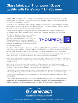
Figure 1 is a sectional View through a glass
capable of forming surfaces having, different drawing chamber showing the coolers in
heat absorptive qualities. '_As is well lmown, place;
I
'
the heat absorptive qualityof a body is de
Figure 2 is a top plan view to enlarged
termined in a large measure by the character scale of one of the coolers;
90
'
of the surface, and I take advantage of this
Figure 3 is a side elevation thereof: and
fact in my-improved cooler. I preferably Fisrure 4 is a similar view but showing a
approximate so-called “black body”-condi slightly different arrangement.
tions on the face of the cooler adjacent the
Figure 1 represents a Fourcault drawing
sheet and make the remaining surface light unit comprising a drawing chamber, indi- 9
in color and reflective in quality.
cated generally by the reference character
may be varied as desired, depending on the . is drawn upwardly by means of draft rollers
conditions encountered. For instance, {he 4 between the coolers 5. Each cooler com
2
‘“ 1,880,788
prises a ?at tank-like body 6 having an inlet absorption by the cooler over diiferent por
pipe 7 with a portion 8_inside'the body of the tions of the surface thereof by treating the
cooler effective for delivering incoming cool different portions of the surface the rate
body 6. The cooling water ?ows crosswise ing greaterthan the rate of heat absorption
ing water at one of the bottom corners of the of heat absorption from the forme sheet be—
and passes out through an exit pipe 9. The.
from the bath.
.
'_
70
v
3. A cooler for use in glass drawing com
pipes 7 and 9 extend beyond the side walls
prisin a body having different surface por
. of thedrawing chamber 2 and are connected
to inlets and outlets inthe usual manner.
tions
i?erently paintedz -
‘
_
4. A cooler for use in glass drawing com 75
prising
a body having different surface por
one side of thebody 6 of the cooler. The
I have indicated at 10 a darkened area- on
10
cooler is made up of sheet metal welded to tions painted with paints of different heat
gether and is painted all over with aluminum absorbing quality.
5. A cooler for use in glass drawing com
paint or the like so as to make the surface
80
15 generally bright and re?ective in quality. prising a body, one part of whose surface 1s
‘ The inlet and outlet pipes are similarly treat-. bright and part of whose surface approxi- ‘
ed. The surface portion 10, however. is made mates that of a black body.
6. A glass drawing apparatus, means for
black by applying an overlying paint coat.
I have successfully employed a mixture of drawing a sheet of glass from a bath, and a
50% lampblack and 50% ultramarine blue, ' cooler adjacent ‘the line .of travel of the sheet,
85
these two pigments being thoroughly mixed the cooler having different surface portions
and applied in a suitable vehicle such as treated in such manner as to produce sur
bronzing?uid. Any good vehicle, such as is. faces of different heat absorbing-quality.
employed for bronzing or aluminum pow- ~
7.IA glass drawingagpparatus, means for 90
from a bath, and a
ders, may be used. The paint is ‘applied over drawing a sheet of g
such portions of the cooler as may be neces cooler adjacent the line of travel of the sheet,
sary to give the desired effect. Such area or the cooler having some surface portions .
areas actrsubst-antially as black‘bodies and bright and some surface portions dark, the
are very e?icient for absorbing heat as com= dark portions approximating a black body.
8. A glass drawing apparatus, means for
pared with the remainder of the cooler. In
practice, the black faces are placed adjacent drawing a sheet of glass from a‘ bath, and a
80
cooler adjacent the line of travel of‘ the
ing effect on the surface of the rising sheet sheet, the cooler having some surface por
the rising sheet so as to effect a strong chill
without undue cooling of the drawing cham tions bright and some surface portions dark,
her. It .will be noted that the end portions of the dark portions being adjacent the rising
the cooler body 6 are left unblackened. thus sheet, and approximately a black body.
reducing the cooling e?iciencv of the end por “9. A glass drawing apparatus, means for
tions. These are the portions which are drawing a sheet of glass from a bath, and a
nearest the sheet edges where strong cooling cooler' adjacent the line of travel of the sheet,
is not so essential.
the cooler having different surface portions
- ~'
105
In Figure 4 I have shown a cooler similar painted with paints of di?erent heat absprf ~'
- '
to that of Figures 2 and 3. but with the black ‘ ing qualities.
10. In the manufacture of glass, the" step
paint arranged in different con?guration.
The width of the, paint coat is reduced ad of drawing a glass sheet past a cooler having 110
Mi jacent the end portions so as to still further different portions coated with paints of dif
reduce the cooling e?iciency of such end por ferent heat absorptive quality.
11. In the manufacture of glass, the step
of
drawing a’ glass sheet past a cooler hav
> I have illustrated and described a present
ing different portions thereof coated with
preferred
embodiment
of
the
invention
as
ap
50
paints'of di?erent heat absorptive quality, 115
plied‘ in the Fourcault process. It will be the
central portions of the cooler having a
‘understood, however. that the invention is greater
coated by paint of high heat ab
not limited to the form shown but maybe sorbing area
quality than the end'portions.
otherwise embodied or practiced within the
‘12. In the manufacture of glass, the step
55. scope of the following claims.
of drawing a sheet of glass past a cooler hav 120
I claim:
‘
‘
ing different parts of the surface thereof
' ' 1“. In the manufacture of glass, the steps treated in such‘ manner as ‘to produce sur
consisting in drawing, the glass past a cooler faces of different heat absorbing quality.
tions.
'
.
and varying the rate of heat absorption by,
13. A cooler for use in glass drawing com
the cooler over different portions of the sur prising a body having different surface por 125
- vface thereof by treating the different por tions treated differently toproduce surfaces
tions of the surface.
. _ of different heat absorbing quality.
A
2. In the manufacture of glass, the steps In testimony whereof I have hereunto set
60
65
consisting in drawing the glass from a bath
past a cooler and varying the rate of’heat
my hand._
LAURENCE P. FORMAN.
.
130


© Copyright 2026