
Object and Event Extraction for Video Processing and Representation
INRS-T´el´ecommunications
Institut national de la recherche scientifique
Object and Event Extraction
for Video Processing and Representation
in On-Line Video Applications
par
Aishy Amer
Th`ese
pr´esent´ee pour l’obtention
du grade de Philosophiae doctor (Ph.D.)
en T´el´ecommunications
Jury d’´evaluation
Examinateur externe
Dr. D. Nair
Examinateur externe
Prof. H. Schr¨oder
Examinateur interne
Prof. D. O’Shaughnessy
Codirecteur de recherche Prof. A. Mitiche
Directeur de recherche
Prof. E. Dubois
c Aishy Amer, Montr´eal, 20 d´ecembre 2001
°
National Instruments, Texas
Universit¨at Dortmund, Allemagne
INRS-T´el´ecommunications
INRS-T´el´ecommunications
Universit´e d’Ottawa
úG YË @ð
ø Q»X
úÍ @
úG ñk @ð
ø YË @ð
úG @ñk @
ø Q»X
:
h ð QË @
X @P
úÍ @
úÍ @
éÒÊ¿
Qº
Acknowledgments
I have enjoyed and benefited from the pleasant and stimulating research environment
at the INRS-T´el´ecommunications. Merci a` tous les membres du centre pour tous les
bons moments.
I am truly grateful to my advisor Prof. Eric Dubois for his wise suggestions and continuously encouraging support during the past four years. I would like also to express
my sincere gratitude to Prof. Amar Mitiche for his wonderful supervision and for the
active contributions to improve the text of this thesis. I also thank Prof. Konrad
for his help during initial work of this thesis. I am also indebted to my colleagues,
in particular Carlos, Fran¸cois, and Souad, for the interesting discussions and for the
active help to enhance this document.
My special thanks go to each member of the dissertation jury for having accepted to
evaluate such a long thesis. I have sincerely appreciated your comments and questions.
Some of the research presented in this text was initiated during my stay at Universit¨at Dortmund, Germany. I would like to thank Prof. Schr¨oder for advising my initial
work. I am also grateful to my German friends, former students, and colleagues, in
particular to Dr. H. Blume, who have greatly helped me in Dortmund. Danke sch¨on.
My deep gratitude to my sisters, my brothers, my nieces, and my nephews who have
supplied me with love and energy throughout my graduate education time. My special thanks go also to Sara, Alia, Marwan, Hakim, and to all my friends for being
supportive despite the distances.
I would like to express my warm appreciations to Hassan for caring and being patient
during the past four years. His understanding provided the strongest motivation to
finish this writing.
BñP
\
à ñºK
Ï
ÕÎ ªÜ @
à@
X A¿
CJjJË @
.
.
é¯ð
ÕÎ ªÒÊË
Õ¯
\
,
ú¯
ú¯
éK Q®Ë @
AÒ»
.
úG YK A @
Ð Y¯ @ð
éJÒÊªË @
.
É¿
éÊgQÜÏ @
á k
QÓ A«
2001
é A«
,
Èð@
à ñK A¿
JÓ
,
QÔ
«
@
ú¯
@ñK X
.
¼P @
Q
JºË @
.
X AJ B @
Ñêʯ
ÑêË
Q
Ð@
g @
áÓ
èQ» A
úÎ ë @
:
ɾK ð
.
éK QªË @
.
,
,
úÍ ñð
úæK Q ¯
X AJ B @
úÍ @
è Yë
úÍ AªË @ð
@ YJ»
áÓ ð
ú¯ ð
Ð Y® K @
á £ñË @
AëP ñJ»
ð
Ì
è AJ m
'@
'
H AK Ym
@
.
.
úG ñÒÊ«
á ÜÏ
Q¢«
H A¯ AK
.
vii
Abstract
As the use of video becomes increasingly popular, and wide spread through, for
instance, broadcast services, Internet, and security-related applications, providing
means for fast, automated, and effective techniques to represent video based on its
content, such as objects and meanings, are important topics of research. In a surveillance application, for instance, object extraction is necessary to detect and classify
object behavior, and with video databases, effective retrieval must be based on highlevel features and semantics. Automated content representation would significantly
facilitate the use and reduce the costs of video retrieval and surveillance by humans.
Most video representation systems are based on low-level quantitative features or
focus on narrow domains. There are few representation schemes based on semantics;
most of these are context-dependent and focus on the constraints of a narrow application and they lack, therefore, generality and flexibility. Most systems assume simple
environments, for example, without object occlusion or noise.
The goal of this thesis is to provide a stable content-based video representation
rich in terms of generic semantic features and moving objects. Objects are represented
using quantitative and qualitative low-level features. Generic semantic features are
represented using events and other high-level motion features. To achieve higher
applicability, content is extracted independently of the type and the context of the
input video.
The proposed system is aimed at three goals: flexible content representation,
reliable stable processing that foregoes the need for precision, and low computational
cost. The proposed system targets video of real environments such as those with
object occlusions and artifacts.
To achieve these goals, three processing levels are proposed: video enhancement
to estimate and reduce noise, video analysis to extract meaningful objects and their
spatio-temporal features, and video interpretation to extract context-independent
semantics such as events. The system is modular, and layered from low-level to
middle-level to high-level where levels exchange information.
The reliability of the proposed system is demonstrated by extensive experimentation on various indoor and outdoor video shots. Reliability is due to noise adaptation
and due to correction or compensation of estimation errors at one step by processing
at subsequent steps where higher-level information is available. The proposed system
provides a response in real-time for applications with a rate of up to 10 frames per
second on a shared computing machine. This response is achieved by dividing each
processing level into simple but effective tasks and avoiding complex operations.
ix
Extraction d’objets et d’´
ev´
enements
pour le traitement et la repr´
esentation
de s´
equences vid´
eo dans des applications en ligne
par Aishy Amer
R´
esum´
e
Table
I.
II.
III.
IV.
V.
VI.
des mati`eres
Contexte et objectif
Page ix
Aper¸cu sur les travaux r´ealis´es
Page xi
Approche propos´ee et m´ethodologie Page xii
R´esultats
Page xviii
Conclusion
Page xix
G´en´eralisation possible
Page xxii
I. Contexte et objectif
L’information visuelle s’est int´egr´e `a tous les secteurs de communication moderne, mˆeme aux services de largeur de bande basse comme la communication mobile. Ainsi, des techniques efficaces pour l’analyse, la description, la manipulation
et la r´ecup´eration d’information visuelle sont des sujets importants et pratiques de
recherche.
La s´equence vid´eo est soumise a` diverses interpr´etations par diff´erents observateurs et la repr´esentation vid´eo bas´ee sur le contenu peut varier selon les observateurs
et les applications. Plusieurs syst`emes existants abordent les probl`emes en essayant
de d´evelopper une solution g´en´erale pour toutes les applications vid´eo. D’autres se
concentrent sur la r´esolution de situations complexes, mais supposent un environnement simple, par exemple la r´esolution d’un probl`eme dans un environnement sans
x
R´esum´e
occlusion et sans bruit ou artefact.
La recherche dans le domaine de traitement vid´eo consid`ere les donn´ees vid´eo
comme ´etant des pixels, des blocs ou des structures globales pour repr´esenter le contenu vid´eo. Cependant, ceci n’est pas suffisant pour des applications vid´eo avanc´ees.
Dans une application de surveillance, par exemple, la repr´esentation vid´eo concernant l’objet n´ecessite la d´etection automatique d’activit´es. Pour des bases de donn´ees
vid´eo, la r´ecup´eration doit ˆetre bas´ee sur la s´emantique. Par cons´equent, une
repr´esentation vid´eo bas´ee contenu est devenue un domaine de recherche fort actif.
Des exemples de cette activit´e sont les standards multim´edia comme MPEG-4 et
MPEG-7 et divers projets de surveillance et recherche dans des bases de donn´ees
visuelles[129, 130].
´
Etant
donn´e la quantit´e croissante de stockage de donn´ees vid´eo, le d´eveloppement
de techniques automatiques et efficaces pour la repr´esentation vid´eo bas´ee sur le contenu, est un probl`eme d’importance croissante. Une telle repr´esentation vid´eo vise une
r´eduction significative de la quantit´e de donn´ees vid´eo en transformant une s´equence
vid´eo de quelques centaines ou milliers d’images en un petit jeu d’information. Cette
r´eduction de donn´ees a deux avantages : premi`erement une grande base de donn´ees
vid´eo peut ˆetre efficacement consult´ee en se basant sur son contenu et, deuxi`emement,
l’utilisation de m´emoire est r´eduite significativement.
Le d´eveloppement de la repr´esentation a` base de contenu exige la r´esolution de
deux probl`emes cl´es : D´efinir les contenus vid´eo int´eressants et les attributs appropri´es
pour repr´esenter ce contenu. L’´etude des propri´et´es du syst`eme visuel humain (SVH)
aide a` r´epondre `a certaines de ces questions. En regardant une s´equence vid´eo, le
SVH est plus sensible aux zones qui se d´eplacent et plus g´en´eralement aux objets
mobiles et a` leurs caract´eristiques. L’int´erˆet dans cette th`ese porte tout d’abord sur
les caract´eristiques de haut niveau des objets (c’est a` dire : la s´emantique) puis `a
ceux de bas niveau (par exemple : la texture). La question principale est alors :
quel est le niveau de s´emantique de l’objet et quelles sont les caract´eristiques les plus
importantes pour des applications vid´eo base´ees contenu ? Par exemple, quelles sont
les descriptions intentionnelles de haut niveau? Une observation importante consiste
`a ce que le sujet de la majorit´e de la s´equence vid´eo soit un objet en mouvement
[105, 72, 56] qui ex´ecute des activit´es et agit pour cr´eer des ´ev´enements. De plus,
le SVH est capable de rechercher des activit´es et des ´ev´enements int´eressants en
parcourant rapidement une s´equence vid´eo. Quelques syst`emes de repr´esentation
vid´eo mettent en oeuvre un tel “flipping” en sautant quelques images sur la base de
dispositifs de bas niveau (par exemple, utilisant l’extraction d’image clefs sur la base
de la couleur) ou en extrayant des indices globaux. Cela peut cependant omettre des
donn´ees int´eressantes parce que le “flipping” doit ˆetre bas´e sur des activit´es d’objet
ou des ´ev´enements combin´es avec des caract´eristiques `a bas niveau comme la forme.
xi
Ceci permettra une recherche et une surveillance vid´eo flexible.
Pour repr´esenter efficacement le signal vid´eo bas´e sur le contenu comme des objets
et des ´ev´enements, trois syst`emes de traitement vid´eo sont n´ecessaires: L’am´elioration
vid´eo pour r´eduire le bruit et l’artefact, l’analyse vid´eo pour extraire les caract´eristiques
vid´eo de bas niveau et l’interpr´etation vid´eo pour d´ecrire le contenu s´emantique.
II. Aper¸cu sur les travaux r´
ealis´
es
R´ecemment, des syst`emes vid´eo incorporant des repr´esentations vid´eo a` base de
contenu ont ´et´e d´evelopp´es. La plupart de la recherche les concernant se concentre
sur des techniques d’analyse vid´eo sans les int´egrer a` un syst`eme vid´eo fonctionnel.
Cela aboutit a` des techniques int´eressantes, mais souvent sans rapport a` l’aspect pratique. En outre, ces syst`emes repr´esentent le signal vid´eo par des caract´eristiques
globales de base comme le mouvement global ou les images clefs. Peu de syst`emes de
repr´esentation vid´eo ont trait´e ce sujet en utilisant des objets. En effet, la plupart
d’entre eux utilisent seulement des caract´eristiques de base comme le mouvement ou
la forme. Les repr´esentations vid´eo a` base d’objets les plus d´evelopp´ees se concentrent dans des domaines ´etroits (par exemple, des sc`enes de football ou le control du
trafic routier). Les syst`emes qui incorporent des repr´esentations vid´eo a` base d’objet
utilisent une description quantitative des donn´ees vid´eo et des objets. Les utilisateurs dans des applications vid´eo avanc´ees comme la recherche vid´eo ne connaissent
pas exactement a` quoi ressemble le signal vid´eo. Ils n’ont pas d’information quantitative exacte: le mouvement, la forme, ou la texture. Donc, des repr´esentations
vid´eo qualitatives faciles a` utiliser pour la recherche vid´eo ou la surveillance sont essentielles. Dans la recherche vid´eo, par exemple, les outils de r´ecup´eration vid´eo les
plus existant demandent `a l’utilisateur un croquis ou une vue de vid´eo, par exemple,
l’utilisateur fait la recherche apr`es examen de la base de donn´ees. Cependant, examiner de grandes bases de donn´ees, peut prendre beaucoup de temps, particuli`erement
pour des sc`enes complexes (c’est `a dire, la sc`ene r´eelle du monde). Des utilisateurs
doivent pouvoir d´ecrire un signal vid´eo par des descripteurs qualitatifs sont essentiels
pour le succ`es de telles applications.
Il y a peu d’ordre dans les activit´es et les ´ev´enements de vues vid´eo. Plusieurs
travaux sur la d´etection et la classification d’´ev´enements se concentrent sur la fa¸con
d’exprimer les ´ev´enements en utilisant des techniques d’intelligence artificielle comme,
par exemple, le raisonnement et l’inf´erence. Autres syst`emes de repr´esentation vid´eo
`a base d’´ev´enements sont developp´es pour des domaines sp´ecifiques.
Malgr´e la grande am´elioration de la qualit´e des syst`emes d’acquisition vid´eo modernes, le bruit reste toujours un probl`eme qui complique les algorithmes de traitement
du signal vid´eo. De plus, des artefacts de codage divers se retrouvent dans un signal
xii
R´esum´e
vid´eo transmis de mani`ere num´erique. Donc, la r´eduction du bruit et des artefacts est
toujours une tˆache importante dans les applications vid´eo. Les artefacts tant sonores
que num´eriques affectent la qualit´e de repr´esentation vid´eo et devraient ˆetre pris en
compte. Tandis que la r´eduction du bruit a ´et´e sujet de plusieurs publications (peu
de m´ethodes traitent des contraintes en temps r´eel) l’impact du codage d’artefact sur
l’ex´ecution du traitement de vid´eo n’est pas suffisamment ´etudi´e.
` cause de progr´es r´ealis´e en micro-´electronique, il est possible d’inclure des techA
niques sophistiqu´ees de traitement vid´eo, dans les services et les appareils. Cependant, l’aspect temps r´eel de ces nouvelles techniques est crucial pour une application
g´en´erale de ces techniques. Plusieurs applications vid´eo n´ecessitant une repr´esentation
du contenu vid´eo `a haut niveau se retrouvent dans un environnement en temps r´eel,
exigeant donc une performance en temps r´eel. Peu d’approches de repr´esentation a`
base de contenu prennent cette contrainte en consid´eration.
III. Approche propos´
ee et m´
ethodologie
L’objectif de cette th`ese est de d´evelopper un syst`eme pour la repr´esentation
vid´eo `a base de contenu par un syst`eme d’extraction automatis´e d’objets int´egr´e
`a un syst`eme de d´etection d’´ev´enements sans l’interaction de l’utilisateur. Le but
est de fournir une repr´esentation a` base de contenu riche en termes d’´ev´enements
g´en´eriques et de traiter une large gamme d’applications vid´eo pratiques. Les objets
sont repr´esent´es par des caract´eristiques a` bas niveau quantitatives et qualitatives.
Les ´ev´enements quant `a eux, sont repr´esent´es par des caract´eristiques haut niveau
des objets telles que les activit´es et les actions.
Cette ´etude ´evoque trois questions importantes : 1. Les repr´esentations d’objets
flexibles qui sont facilement d´etectables pour la r´ecapitulation, l’indexation et la manipulation vid´eo, 2. L’interpr´etation du signal vid´eo fiable et stable qui pr´ec`ede le
besoin de la pr´ecision et 3. Economie en temps de calcul. Ceci n´ecessite la contribution d’algorithmes qui r´epondent `a ces trois questions pour la r´ealisation des
applications vid´eo bas´ees sur le contenu et destin´ees au consommateur, comme la
surveillance et la recherche dans des bases de donn´ees vid´eo. Ces algorithmes doivent
se concentrer sur les questions pratiques d’analyse vid´eo orient´ee vers les besoins de
syst`emes vid´eo bas´es sur l’objet et l’´ev´enement.
Vue vidéo
Amélioration vidéo
Analyse vidéo
orienté object
Interprétation vidéo
orienté événement
Descripteurs
d’objets &
d’événements
Figure 1: Synoptique du syst`eme propos´e.
Le syst`eme propos´e est con¸cu pour des situations r´eelles avec des occlusions
xiii
d’objets, des changements d’illumination, du bruit et des artefacts. Pour produire
une repr´esentation vid´eo de haut niveau, la structure propos´ee implique trois ´etapes
(voir figure 1) : am´elioration, analyse et interpr´etation. Le signal vid´eo original
est pr´esent´e `a l’entr´ee du module am´elioration vid´eo et la sortie en est une version
am´elior´ee. Ce signal vid´eo am´elior´e est alors trait´e par le module d’analyse vid´eo qui
produit une description bas niveau de ce vid´eo. Le module interpr´etation vid´eo re¸coit
ces descriptions `a bas niveau et produit une description de haut niveau du signal vid´eo
original. Les r´esultats d’une ´etape sont int´egr´es pour soutenir les ´etapes suivantes
qui corrigent ou soutiennent a` leur tour les pas pr´ec´edents. Par exemple, un objet
suivi `a une ´etape est soutenu par la segmentation bas niveau. Les r´esultats du suivi
sont a` leur tour int´egr´es dans la segmentation pour la confirmer. Cette approche,
par analogie au syst`eme visuel humain (SVH), trouve des objets o`
u la d´etection partielle et l’identification pr´esentent un nouveau contexte qui approuve a` son tour la
nouvelle identification [103, 3]. Le syst`eme peut ˆetre vu comme une structure de
m´ethodes et d’algorithmes pour construire des syst`emes d’interpr´etation de sc`enes
dynamiques automatiques. La robustesse des m´ethodes propos´ees sera d´emontr´ee
par une exp´erimentation vaste sur des s´equences vid´eo bien connues. La robustesse
est le r´esultat de l’adaptation au bruit vid´eo et aux artefacts est due au traitement
qui consid`ere les erreurs (obtenues) `a une ´etape pour la correction ou la compensation
`a l’´etape suivante.
La structure propos´ee dans cette th`ese est con¸cue pour des applications o`
u une
interpr´etation du vid´eo d’entr´ee est n´ecessaire (“quel est le sujet de la s´equence”).
Ceci peut ˆetre illustr´e par deux exemples : surveillance et recherche vid´eo. Dans
un syst`eme de surveillance vid´eo, une alarme peut ˆetre activ´ee dans le cas o`
u le
syst`eme propos´e d´etecte un comportement d’objets particulier. Dans un syst`eme de
r´ecup´eration vid´eo, les utilisateurs peuvent rechercher un vid´eo en fournissant une
description qualitative, utilisant une information comme les attributs d’objet (par
exemple, la forme), les rapports spatiaux (par exemple : l’objet i est pr`es de l’objet
j), l’emplacement (par exemple : l’objet i est au fond de l’image) et les caract´eristiques
s´emantiques ou de haut niveau (par exemple, action d’objet : l’objet i se deplace a`
gauche et est ensuite occlus; ´ev´enement : le d´eplacement ou le d´epˆot d’objets). Le
syst`eme de r´ecup´eration peut alors trouver les trames dont le contenu correspond
le mieux a` la description qualitative. Une propri´et´e d´esirable pour les strat´egies de
repr´esentation vid´eo est de fournir une r´eponse `a des questions simples bas´ees sur
l’observation, comme par exemple, comment s´electionner des objets (qui est dans la
sc`ene), d´ecrire leur action (qu’est-ce qu’il/elle fait) et d´eterminer leur emplacement
(“o`
u” l’action a eu lieu) [72, 56]. En l’absence d’une application sp´ecifique, un mod`ele
g´en´erique doit ˆetre adaptable (par exemple, avec de nouvelles d´efinitions d’actions et
d´ev´enements).
xiv
R´esum´e
Sans consid´eration au temps r´eel, une approche de repr´esentation vid´eo `a base de
contenu pourrait perdre son applicabilit´e. En outre, la robustesse au bruit et artefacts
du codage est importante pour une utilisation de la solution. Le syst`eme propos´e est
con¸cu pour r´ealiser un ´equilibre entre efficacit´e, qualit´e de la solution et temps de
calcul. Le syst`eme repr´esent´e dans la figure 2 se d´ecrit ainsi:
• Le chapitre de l’am´elioration vid´eo classifie d’abord le bruit et les artefacts
dans le vid´eo puis utilise une nouvelle m´ethode pour l’estimation du bruit et
une autre pour la r´eduction spatiale du bruit (le Chapitre 2). La technique
d’estimation du bruit propos´ee produit des ´evaluations fiables dans des images
ayant des r´egions lisses et/ou structur´ees. Cette technique est une m´ethode `a
base de blocs qui prend en compte la structure de l’image en consid´eration et qui
utilise une mesure autre que la variance pour d´eterminer si un bloc est homog`ene
ou non. Elle n’utilise aucun seuil et automatise la proc´edure avec laquelle les
m´ethodes `a base de blocs proc`edent pour la moyennisation des variances de
blocs. Cette nouvelle technique de r´eduction spatiale du bruit utilise un filtre
pass-bas ayant une complexit´e r´eduite pour ´eliminer le bruit spatial non corr´el´e.
L’id´ee de base est d’utiliser un ensemble de filtres pass-haut pour d´etecter la
direction de filtrage la plus appropri´ee. Le filtre propos´e r´eduit le bruit dans
l’image en pr´eservant la structure, et est adapt´e `a la quantit´e du bruit estim´ee.
• L’analyse vid´eo est bas´ee principalement sur l’extraction des objets significatifs et des caract´eristiques quantitatives a` bas niveau a` partir de la vid´eo. La
m´ethode se fait en quatre ´etapes (les Chapitres 3-6):
◦
◦
◦
◦
segmentation des objets bas´ee sur la d´etection du mouvement,
estimation du mouvement bas´ee objet,
fusion de r´egions,
suivi d’objets bas´e sur une combinaison non lin´eaire de caract´eristiques
spatio-temporelles.
L’algorithme propos´e extrait les objets vid´eo importants pouvant ˆetre utilis´es
comme index dans les vid´eo bas´es sur la repr´esentation d’objets flexibles et pour
analyser la vid´eo afin de d´etecter les ´ev´enements li´es aux objets en vue d’une
repr´esentation et une interpr´etation s´emantique.
• La m´ethode de segmentation d’objets propos´ee classifie les pixels des images
vid´eo comme appartenant a` des objets distincts bas´es sur le mouvement et des
caract´eristiques de contour (le Chapitre 4). Elle comporte des proc´edures
simples, et est r´ealis´ee en quatre ´etapes :
◦ binarisation des images en entr´ee bas´ee sur la d´etection du mouvement.
◦ d´etection morphologique des fronti`eres.
◦ analyse des contours et la squ´eletisation.
xv
◦ ´etiquetage des objets.
La tˆache la plus critique est la binarisation qui doit ˆetre fiable dans toute la
s´equence vid´eo. L’algorithme de binarisation m´emorise le mouvement d´etect´e
pr´ec´edemment pour adapter le processus. La d´etection de fronti`eres fait appel
`a de nouvelles op´erations morphologiques dont les calculs sont r´eduits de facc
importante. L’avantage de la d´etection morphologique consiste en la g´en´eration
de fronti`eres continues d’un seul pixel de largeur. L’analyse de contour transforme les fronti`eres en contours et ´elimine les contours non d´esir´es. Cependant,
les petits contours sont seulement ´elimin´es s’ils ne peuvent ˆetre associ´es `a des
contours pr´ec´edemment extraits, c’est a` dire, si un petit contour n’a aucun contour correspondant dans l’image pr´ec´edente. Les petits contours se trouvant
compl`etement `a l’int´erieur d’un grand contour sont fusionn´es avec ce dernier
selon des crit`eres d’homog´en´eit´e.
• L’estimation du mouvement d´etermine l’´etendue et la direction du mouvement,
de l’objet extrait (le Chapitre 5). Dans l’approche propos´ee, l’information
extraite de l’objet (par exemple, la taille, la boite a` contour minimal (MBB :
Minimum bounding box), la position, la direction du mouvement) est utilis´ee
dans un processus `a base de r`egles ayant trois ´etapes : la correspondance d’objet,
l’estimation du mouvement MBB bas´e sur le d´eplacement des cˆot´es du MBB,
ce qui rend le processus d’estimation ind´ependant du signal d’intensit´e et du
type de mouvement de l’objet.
• La m´ethode de suivi suit et associe les objets en mouvement et enregistre leurs
caract´eristiques temporelles. Elle transforme les objets segment´es provenant du
processus de segmentation a` des objets de vid´eo (le Chapitre 6). Le principal
probl`eme des syst`emes de suivi est leur fiabilit´e en cas d’occlusion, d’ombrage
et de division d’objets. La m´ethode de suivi propos´ee est bas´ee sur un syst`eme
de vote non-lin´eaire pour r´esoudre le probl`eme de correspondances multiples.
Le probl`eme d’occlusion est att´enu´e par une proc´edure de d´etection simple
bas´ee sur les d´eplacements estim´es du MBB de l’objet, suivie d’une proc´edure
de pr´ediction bas´ee m´ediane qui fournit un estim´e raisonnable pour les objets
occlus (partiellement ou compl`etement). Les objets sont suivis une fois qu’ils entrent en sc`ene et aussi pendant l’occlusion, chose tr´es importante pour l’analyse
d’activit´e. Des r`egles de plausibilit´e pour la coh´erence, l’allocation d’erreur (error allowance) et le contrˆole sont propos´ees pour un suivi efficace pendant de
longues p´eriodes. Une contribution importante au niveau du suivi est la fusion
des r´egions fiables qui am´eliore la performance du syst`eme d’analyse vid´eo en
entier. L’algorithme propos´e a ´et´e d´evelopp´e pour des applications vid´eo bas´ees
sur le contenu comme la surveillance ou l’indexation et la r´ecup´eration.
• L’interpr´etation vid´eo est principalement concern´ee par l’extraction de car-
xvi
R´esum´e
act´eristiques vid´eo qualitatives et s´emantiques (le Chapitre 7). Son objectif
principal est de fournir des outils de repr´esentation par une combinaison des
caract´eristiques a` bas niveau, ainsi que des donn´ees vid´eo a` haut niveau. Cette
int´egration est essentielle pour faire face au contenu visuel g´en´erique ´enorme
contenu dans une s´equence vid´eo. L’accent est donc mis sur la r´ealisation d’une
proc´edure de d´etection d’´ev´enements g´en´eriques simple, robuste et automatique. Pour identifier les ´ev´enements, une description qualitative du mouvement de l’objet est un pas important vers l’association des caract´eristiques de
` cette fin,
base au processus de r´ecup´eration des caract´eristiques haut niveau. A
le comportement du mouvement des objets vid´eo est analys´e pour repr´esenter
les ´ev´enements ainsi que les actions importantes. Cela signifie que les caract´eristiques de base peuvent ˆetre combin´ees de mani`ere `a produire un effet sur
celles de haut niveau. D’abord des descriptions qualitatives des caract´eristiques
bas niveau des objets ainsi que les relations entre objets sont d´eriv´ees. Ensuite, des m´ethodes automatiques pour la repr´esentation vid´eo des contenus
haut niveau bas´ees sur les ´ev´enements sont propos´ees.
Le but du vid´eo est, en g´en´eral, de documenter les ´ev´enements et les activit´es
des objets ou ensemble d’objets. Les utilisateurs g´en´eralement recherchent des
objets vid´eo qui v´ehiculent un certain message [124] et ils captent et retiennent
en m´emoire [72, 56] : 1) des ´ev´enements (“ce qui est arriv´e”), 2) des objets
(“qui est dans la sc`ene”), 3) des emplacements (“o`
u cela arrive”), et 4) le temps
(“quand cela est arriv´e”).
Les utilisateurs sont ainsi attir´es par les objets et leurs caract´eristiques et se
concentrent d’abord sur les caract´eristiques a` haut niveau li´ees au mouvement.
En cons´equence, l’analyse vid´eo propos´ee est con¸cue pour :
◦ prendre des d´ecisions sur des donn´ees de plus bas niveau pour supporter
les niveaux suivants de traitement,
◦ repr´esenter qualitativement les objets ainsi que leurs caract´eristiques spatiales, temporelles et relationnelles,
◦ extraire les caract´eristiques s´emantiques des objets, qui sont g´en´eralement
utiles et
◦ fournir automatiquement et efficacement une r´eponse (op´eration en temps
r´eel).
xvii
Vue vidéo
Amélioration vidéo
Estimation & réduction
du bruit
Vidéo amélioré
Vidéo amélioré
Stabilisation de l’image
Extraction des attributs
globaux
Vidéo stable
Mise à jour de
Compensation du mouvement
l’arrière-plan
global
σn
Vidéo stable
Analyse vidéo
Segmentation d’objets basée sur
le mouvement => Pixels à objets
Pixels à vidéo objets
Estimation de mouvements
basée sur l’objet
Suivie d’objet basée sur le vote
=> Objets à vidéo objets
Descripteurs d’objets
spatio-temporal
Descripteurs globaux
de vue
Interprétation vidéo
Objets vidéo à évènements
Analyse & interprétation
des descripteurs à bas niveau
Détection & classification
d’événements
Résultats
Requète
(événements & objets)
Application basée sur l’objet et le mouvement
exemple: Décision basée sur l’événement
Figure 2: Diagramme de la structure propos´ee pour la repr´esentation de s´equence
vid´eo a` base d’objets et d’´ev´enements. Les contributions sont sch´ematis´ees par des
blocs de couleur grise et les interactions entre module sont marqu´ees par des fl`eches
en pointill´es. σn est l’´ecart-type du bruit d’image.
xviii
R´esum´e
IV. R´
esultats
Dans les applications vid´eo en temps r´eel, une analyse vid´eo orient´ee objet non
supervis´ee et rapide est n´ecessaire. Une ´evaluation tant objective que subjective et des
comparaisons montrent la robustesse de la m´ethode d’analyse vid´eo propos´ee sur des
images bruit´ees ainsi que sur des images pr´esentant des changements d’illumination,
alors que la complexit´e de cette m´ethode est r´eduite. Cette derni`ere utilise peu de
param`etres qui sont automatiquement ajust´es au bruit et aux changements temporels
dans la s´equence vid´eo (la figure 3 illustre un exemple d’analyse vid´eo de la s´equence
‘Autoroute’).
Cette th`ese propose un sch´ema d’interpr´etation vid´eo orient´e ´ev´enements. Pour
d´etecter les ´ev´enements, des descriptions perceptuelles des ´ev´enements communes
pour une large gamme d’applications sont propos´ees. Les ´ev´enements d´etect´es incluent : {entrer, apparaitre, sortir, disparaitre, se d´eplacer, arrˆeter, occluer/est Occlu´e,
a enlev´e/a ´et´e enlev´e, d´epos´e/a ´et´e d´epos´e, mouvement anormal }. Pour d´etecter
les ´ev´enements, le syst`eme propos´e contrˆole le comportement et les caract´eristiques
de chaque objet dans la sc`ene. Si des conditions sp´ecifiques sont rencontr´ees, les
´ev´enements li´es `a ces conditions sont d´etect´es. L’analyse des ´ev´enements est faite en
ligne, c’est a` dire, les ´ev´enements sont d´etect´es quand ils arrivent. Des caract´eristiques
sp´ecifiques telles que le mouvement ou la taille de l’objet sont m´emoris´ees pour chaque
image et sont compar´ees aux images suivantes dans la s´equence. La d´etection des
´ev´enements n’est pas bas´ee sur la g´eom´etrie des objets, mais sur leurs caract´eristiques
et relations dans le temps. La th`ese propose des mod`eles approximatifs mais efficaces
pour d´efinir les ´ev´enements utiles. Dans diverses applications, ces mod`eles approximatifs mˆeme s’ils ne sont pas pr´ecis, sont ad´equats.
Des exp´eriences utilisant des s´equences vid´eo bien connues ont permis de v´erifier
l’efficacit´e de l’´etude propos´ee (par exemple la figure 4). Les ´ev´enements d´etect´es
sont suffisamment communs pour une large gamme d’applications vid´eo pour aider
la surveillance et la recherche vid´eos. Par exemple:
1) le d´eplacement/d´epˆot d’objets dans un site de surveillance peut ˆetre contrˆol´e et
d´etect´e d`es qu’il arrive,
2) le d´eplacement des objets en mouvement peut ˆetre contrˆol´e et annonc´e, et
3) le comportement de clients dans des magasins ou des passages souterrains peut
ˆetre surveill´e.
Le syst`eme en entier (l’analyse vid´eo et l’interpr´etation) n´ecessite en moyenne entre 0.12 et 0.35 secondes pour traiter les donn´ees entre deux images. Typiquement,
la vid´eo surveillance est enregistr´e `a une vitesse de 3 `a 15 images par seconde. Le
syst`eme propos´e produit une r´eponse en temps r´eel pour des applications de surveillance avec une vitesse de 3 a` 10 images par seconde. Afin d’augmenter la performance
xix
du syst`eme pour des applications o`
u la fr´equence des images est ´elev´ee, l’optimisation
du code est n´ecessaire. Une acc´el´eration du processus peut ˆetre r´ealis´ee, i) en optimisant l’impl´ementation des occlusions et de la s´eparation d’objets, ii) en optimisant
l’impl´ementation des techniques de d´etection du changement et iii) en travaillant
avec des valeurs de type entier au lieu des r´eels (quand c’est appropri´e) et avec des
op´erations d’addition au lieu des multiplications.
V. Conclusion
Cette ´etude a apport´e un nouveau mod`ele pour le traitement et la repr´esentation
vid´eo d’une fa¸con ind´ependante du contexte et bas´e sur les objets et les ´evenements.
Le traitement et la repr´esentation vid´eo bas´es sur objet-´ev´enement sont n´ecessaires
pour la recherche automatique de base de donn´ees vid´eo et pour la surveillance
vid´eo. Ce mod`ele repr´esente la s´equence vid´eo en termes d’objets, un ensemble
riche d’´ev´enements g´en´eriques pouvant supporter des applications vid´eo bas´ees sur le
contenu et orient´ees utilisateur. Il permet une analyse efficace et flexible et une interpr´etation de la s´equence vid´eo dans des environnements r´eels o`
u occlusions, changements d’illumination, bruit et artefacts peuvent survenir.
` partir du mod`ele propos´e, le traitement se fait sur des niveaux, allant du bas
A
niveau au haut niveau en passant par un niveau interm´ediaire. Chaque niveau est organis´e de facon modulaire et est responsable d’un certain nombre d’aspects sp´ecifiques
d’analyse. Les r´esultats du traitement du niveau inf´erieur sont int´egr´es pour appuyer
le traitement aux niveaux sup´erieurs.
Les trois niveaux de traitement sont :
Am´
elioration vid´
eo Une nouvelle m´ethode pour le filtrage du bruit spatial, pr´eservant
la structure et `a complexit´e r´eduite a ´et´e d´evelopp´ee. Cette m´ethode de filtrage est
soutenue par une proc´edure qui estime correctement le bruit dans l’image. Le bruit
estim´e est aussi utilis´e pour soutenir l’analyse vid´eo qui suit (le Chapitre 2).
Analyse vid´
eo Une m´ethode d’extraction d’objets vid´eo significatifs et de leurs caract´eristiques d´etaill´ees a ´et´e d´evelopp´ee. Elle est bas´ee sur une segmentation fiable
et efficace du point de vue calcul, ainsi que sur le suivi d’objets. Elle est tol´erante
aux erreurs et peut corriger et d´etecter les erreurs. Le syst`eme peut fournir une
r´eponse en temps r´eel pour des applications de surveillance a` une vitesse de 3 a` 10
images par seconde. La m´ethode de suivi est efficace et applicable `a une large classe de
s´equences vid´eo. L’efficacit´e du syst`eme d’analyse vid´eo a ´et´e d´emontr´ee par plusieurs
exp´eriences stimulantes (les Chapitres 3-6).
Interpr´
etation vid´
eo Un syst`eme d’interpr´etation vid´eo ind´ependant du contexte a
´et´e d´evelopp´e. Il permet une repr´esentation vid´eo assez riche en termes d’´ev´enements
g´en´eriques et de caract´eristiques qualitatives d’objets, ce qui fait de lui un syst`eme
xx
R´esum´e
StartP:1
ObjID: 1
StartP:2
ObjID: 2
StartP:3
ObjID: 3
StartP:4
ObjID: 4
StartP:5
ObjID: 5
(a) La trajectoire de l’objet dans le plan image.
StartP:1
ObjID: 1
StartP:2
ObjID: 2
StartP:3
ObjID: 3
StartP:4
ObjID: 4
StartP:5
ObjID: 5
0
50
100
0
50
100
150
x
y 150
200
StartP:1
ObjID: 1
StartP:2
ObjID: 2
StartP:3
ObjID: 3
StartP:4
ObjID: 4
StartP:5
ObjID: 5
200
250
250
300
350
0
50
100
150
200
250
Img No.
(b) La trajectoire pour la direction horizontale.
300
300
0
50
100
150
200
250
300
Img No.
(c) La trajectoire pour la direction verticale.
Figure 3: Trajectoire des objets dans le s´equence ‘Autoroute’. Fig. 3(b) and (c)
permet une interpr´etation du comportement du mouvement de l’objet: par exemple,
O2 d´emarre `a gauche de l’image et se d´eplace jusqu’`a la fronti`ere de l’image. Des
objets divers entrent dans la sc`ene `a plusieurs reprises. Quelques objets se d´eplacent
vite tandis que d’autres sont plus lents. Le syst`eme suit tous les objets r´eguli`erement.
xxi
Figure 4: Images d’´ev´enements clefs de la s´equence ‘Hall’. Cette s´equence est un
exemple d’une application de surveillance a` l’int´erieur. ´ev´enement clef: O6 est d´epos´e
par l’objet O1 .
xxii
pouvant ˆetre utilis´e pour une large gamme d’applications. Des descripteurs d’objet
qualitatifs sont extraits par quantification des descriptions param´etriques des objets.
Pour extraire les ´ev´enements, des changements de mouvement et des caract´eristiques
sont continuellement trait´ees. Les ´ev´enements sont d´etect´es quand les conditions qui
les d´efinissent sont rencontr´ees. Des exp´eriences utilisant des s´equences vid´eo bien
connues ont d´emontr´e l’efficacit´e de la technique propos´e (le Chapitre 7).
VI. G´
en´
eralisation possible
Il y a un certain nombres de questions a` consid´erer si on veut am´eliorer la performance du syst`eme propos´e et ´elargir ses domaines d’applications.
• Temps d’ex´
ecution L’impl´ementation peut ˆetre optimis´ee pour une ex´ecution
plus rapide.
• Segmentation d’objet Dans le contexte du codage vid´eo MPEG, les vecteurs
de mouvement sont disponibles. Une extension imm´ediate de la technique de
segmentation propos´ee est d’int´egrer l’information du mouvement a` partir du
flot MPEG (MPEG-stream) pour supporter la segmentation d’objet. Cette
int´egration aurait pour but d’am´eliorer la segmentation sans une augmentation
significative du coˆ
ut de calcul.
• Estimation du mouvement Le mod`ele de mouvement propos´e peut ˆetre encore am´elior´e pour permettre une estimation plus pr´ecise. Une extension directe serait d’examiner les d´eplacements des extensions diagonales de l’objet
et d’adapter l’estimation du mouvement pr´ec´edemment ´evalu´e pour une plus
grande stabilit´e.
• Points culminants et ombres Le syst`eme peut profiter de la d´etection d’ombres
et de la compensation de leurs effets.
• Stabilisation de l’image Les techniques de stabilisation d’image peuvent ˆetre
utilis´ees pour permettre une analyse des donn´ees vid´eo `a partir de d´eplacement
de cam´eras et de changement d’arri`ere-plans.
• Interpr´
etation vid´
eo Un ensemble plus large d’´ev´enements peut ˆetre consid´er´e pour servir un ensemble plus grand d’applications. Une interface peut
ˆetre con¸cue pour faciliter l’interaction entre le syst`eme et l’utilisateur. La
d´efinition d’une telle interface exige une ´etude du besoin des utilisateurs de
ces applications vid´eo. Une classification des objets en mouvement et un mouvement de d´esordre (clutter motion) tel que le mouvement des arbres dans le
vent, peut ˆetre utilis´e pour rejeter des ´ev´enements. Une classification possible
est de diff´erencier entre un mouvement avec but (celui d’un v´ehicule ou d’une
personne) et un mouvement sans but.
Contents
R´
esum´
e
vii
1 Introduction
1.1 Background and objective . . . . . .
1.2 Review of related work . . . . . . . .
1.3 Proposed approach and methodology
1.4 Contributions . . . . . . . . . . . . .
1.5 Thesis outline . . . . . . . . . . . . .
.
.
.
.
.
.
.
.
.
.
.
.
.
.
.
.
.
.
.
.
.
.
.
.
.
.
.
.
.
.
.
.
.
.
.
.
.
.
.
.
.
.
.
.
.
.
.
.
.
.
.
.
.
.
.
2 Video Enhancement
2.1 Motivation . . . . . . . . . . . . . . . . . . . . . . . . . .
2.2 Noise and artifacts in video signals . . . . . . . . . . . .
2.3 Modeling of image noise . . . . . . . . . . . . . . . . . .
2.4 Noise estimation . . . . . . . . . . . . . . . . . . . . . .
2.4.1 Review of related work . . . . . . . . . . . . . . .
2.4.2 A homogeneity-oriented noise estimation . . . . .
2.4.3 Evaluation and comparison . . . . . . . . . . . .
2.4.4 Summary . . . . . . . . . . . . . . . . . . . . . .
2.5 Spatial noise reduction . . . . . . . . . . . . . . . . . . .
2.5.1 Review of related work . . . . . . . . . . . . . . .
2.5.2 Fast structure-preserving noise reduction method
2.5.3 Adaptation to image content and noise . . . . . .
2.5.4 Results and conclusions . . . . . . . . . . . . . .
2.5.5 Summary . . . . . . . . . . . . . . . . . . . . . .
3 Object-Oriented Video Analysis
3.1 Introduction . . . . . . . . . . . . .
3.2 Fundamental issues . . . . . . . . .
3.3 Related work . . . . . . . . . . . .
3.4 Overview of the proposed approach
3.5 Feature selection . . . . . . . . . .
3.5.1 Selection criteria . . . . . .
3.5.2 Feature descriptors . . . . .
3.6 Summary and outlook . . . . . . .
xxiii
.
.
.
.
.
.
.
.
.
.
.
.
.
.
.
.
.
.
.
.
.
.
.
.
.
.
.
.
.
.
.
.
.
.
.
.
.
.
.
.
.
.
.
.
.
.
.
.
.
.
.
.
.
.
.
.
.
.
.
.
.
.
.
.
.
.
.
.
.
.
.
.
.
.
.
.
.
.
.
.
.
.
.
.
.
.
.
.
.
.
.
.
.
.
.
.
.
.
.
.
.
.
.
.
.
.
.
.
.
.
.
.
.
.
.
.
.
.
.
.
.
.
.
.
.
.
.
.
.
.
.
.
.
.
.
.
.
.
.
.
.
.
.
.
.
.
.
.
.
.
.
.
.
.
.
.
.
.
.
.
.
.
.
.
.
.
.
.
.
.
.
.
.
.
.
.
.
.
.
.
.
.
.
.
.
.
.
.
.
.
.
.
.
.
.
.
.
.
.
.
.
.
.
.
.
.
.
.
.
.
.
.
.
.
.
.
.
.
.
.
.
.
.
.
.
.
.
.
.
.
.
.
.
.
.
.
.
.
.
.
.
.
.
.
.
.
.
.
.
.
.
.
.
.
.
.
.
.
.
.
.
.
.
1
1
3
4
8
9
.
.
.
.
.
.
.
.
.
.
.
.
.
.
11
11
13
15
16
16
18
20
24
24
24
28
29
31
33
.
.
.
.
.
.
.
.
39
39
41
42
44
46
46
48
51
xxiv
3.6.1
3.6.2
Summary . . . . . . . . . . . . . . . . . . . . . . . . . . . . .
Outlook . . . . . . . . . . . . . . . . . . . . . . . . . . . . . .
4 Object Segmentation
4.1 Motivation . . . . . . . . . . . . . . . . . . . . . . . . .
4.2 Overall approach . . . . . . . . . . . . . . . . . . . . .
4.3 Motion detection . . . . . . . . . . . . . . . . . . . . .
4.3.1 Related work . . . . . . . . . . . . . . . . . . .
4.3.2 A memory-based motion detection method . . .
4.3.3 Results and comparison . . . . . . . . . . . . .
4.4 Thresholding for motion detection . . . . . . . . . . . .
4.4.1 Introduction . . . . . . . . . . . . . . . . . . . .
4.4.2 Review of thresholding methods . . . . . . . . .
4.4.3 Artifact-adaptive thresholding . . . . . . . . . .
4.4.4 Experimental results . . . . . . . . . . . . . . .
4.5 Morphological operations . . . . . . . . . . . . . . . . .
4.5.1 Introduction . . . . . . . . . . . . . . . . . . . .
4.5.2 Motivation for new operations . . . . . . . . . .
4.5.3 New morphological operations . . . . . . . . . .
4.5.4 Comparison and discussion . . . . . . . . . . . .
4.5.5 Morphological post-processing of binary images
4.6 Contour-based object labeling . . . . . . . . . . . . . .
4.6.1 Contour tracing . . . . . . . . . . . . . . . . . .
4.6.2 Object labeling . . . . . . . . . . . . . . . . . .
4.7 Evaluation of the segmentation method . . . . . . . . .
4.7.1 Evaluation criteria . . . . . . . . . . . . . . . .
4.7.2 Evaluation and comparison . . . . . . . . . . .
4.8 Summary . . . . . . . . . . . . . . . . . . . . . . . . .
5 Object-Based Motion Estimation
5.1 Introduction . . . . . . . . . . . . . . . . . .
5.2 Review of methods and motivation . . . . .
5.3 Modeling object motion . . . . . . . . . . .
5.4 Motion estimation based on object-matching
5.4.1 Overall approach . . . . . . . . . . .
5.4.2 Initial estimation . . . . . . . . . . .
5.4.3 Motion analysis and update . . . . .
5.5 Experimental results and discussion . . . . .
5.5.1 Evaluation criteria . . . . . . . . . .
5.5.2 Evaluation and discussion . . . . . .
5.6 Summary . . . . . . . . . . . . . . . . . . .
.
.
.
.
.
.
.
.
.
.
.
.
.
.
.
.
.
.
.
.
.
.
.
.
.
.
.
.
.
.
.
.
.
.
.
.
.
.
.
.
.
.
.
.
.
.
.
.
.
.
.
.
.
.
.
.
.
.
.
.
.
.
.
.
.
.
.
.
.
.
.
.
.
.
.
.
.
.
.
.
.
.
.
.
.
.
.
.
.
.
.
.
.
.
.
.
.
.
.
.
.
.
.
.
.
.
.
.
.
.
.
.
.
.
.
.
.
.
.
.
.
.
.
.
.
.
.
.
.
.
.
.
.
.
.
.
.
.
.
.
.
.
.
.
.
.
.
.
.
.
.
.
.
.
.
.
.
.
.
.
.
.
.
.
.
.
.
.
.
.
.
.
.
.
.
.
.
.
.
.
.
.
.
.
.
.
.
.
.
.
.
.
.
.
.
.
.
.
.
.
.
.
.
.
.
.
.
.
.
.
.
.
.
.
.
.
.
.
.
.
.
.
.
.
.
.
.
.
.
.
.
.
.
.
.
.
.
.
.
.
.
.
.
.
.
.
.
.
.
.
.
.
.
.
.
.
.
.
.
.
.
.
.
.
.
.
.
.
.
.
.
.
.
.
.
.
.
.
.
.
.
.
.
.
.
.
.
.
.
.
.
.
.
.
.
.
.
.
.
.
.
.
.
.
.
.
.
.
.
.
.
51
52
.
.
.
.
.
.
.
.
.
.
.
.
.
.
.
.
.
.
.
.
.
.
.
.
53
53
54
54
56
58
60
61
61
61
64
66
67
67
71
72
75
76
77
77
81
81
81
82
84
.
.
.
.
.
.
.
.
.
.
.
91
91
92
94
95
95
96
98
102
102
103
107
xxv
6 Voting-Based Object Tracking
6.1 Introduction . . . . . . . . . . . . . . . . . .
6.2 Review of tracking algorithms . . . . . . . .
6.3 Non-linear object tracking by feature voting
6.3.1 HVS-related considerations . . . . . .
6.3.2 Overall approach . . . . . . . . . . .
6.3.3 Feature selection . . . . . . . . . . .
6.3.4 Feature integration by voting . . . .
6.3.5 Feature monitoring and correction . .
6.3.6 Region merging . . . . . . . . . . . .
6.3.7 Feature filtering . . . . . . . . . . . .
6.4 Results and discussions . . . . . . . . . . . .
6.5 Summary and outlook . . . . . . . . . . . .
.
.
.
.
.
.
.
.
.
.
.
.
109
109
110
112
112
113
116
117
122
125
127
129
131
.
.
.
.
.
.
.
.
.
.
.
.
.
.
145
145
145
147
149
150
153
153
153
155
156
163
165
169
170
8 Conclusion
8.1 Review of the thesis background . . . . . . . . . . . . . . . . . . . . .
8.2 Summary of contributions . . . . . . . . . . . . . . . . . . . . . . . .
8.3 Possible extensions . . . . . . . . . . . . . . . . . . . . . . . . . . . .
181
181
181
184
Bibliography
185
7 Video Interpretation
7.1 Introduction . . . . . . . . . . . . . . . . . .
7.1.1 Video representation strategies . . .
7.1.2 Problem statement . . . . . . . . . .
7.1.3 Related work . . . . . . . . . . . . .
7.1.4 Proposed framework . . . . . . . . .
7.2 Object-based representation . . . . . . . . .
7.2.1 Spatial features . . . . . . . . . . . .
7.2.2 Temporal features . . . . . . . . . . .
7.2.3 Object-relation features . . . . . . .
7.3 Event-based representation . . . . . . . . . .
7.4 Results and discussions . . . . . . . . . . . .
7.4.1 Event-based video summary . . . . .
7.4.2 Key-image based video representation
7.5 Summary . . . . . . . . . . . . . . . . . . .
.
.
.
.
.
.
.
.
.
.
.
.
.
.
.
.
.
.
.
.
.
.
.
.
.
.
.
.
.
.
.
.
.
.
.
.
.
.
.
.
.
.
.
.
.
.
.
.
.
.
.
.
.
.
.
.
.
.
.
.
.
.
.
.
.
.
.
.
.
.
.
.
.
.
.
.
.
.
.
.
.
.
.
.
.
.
.
.
.
.
.
.
.
.
.
.
.
.
.
.
.
.
.
.
.
.
.
.
.
.
.
.
.
.
.
.
.
.
.
.
.
.
.
.
.
.
.
.
.
.
.
.
.
.
.
.
.
.
.
.
.
.
.
.
.
.
.
.
.
.
.
.
.
.
.
.
.
.
.
.
.
.
.
.
.
.
.
.
.
.
.
.
.
.
.
.
.
.
.
.
.
.
.
.
.
.
.
.
.
.
.
.
.
.
.
.
.
.
.
.
.
.
.
.
.
.
.
.
.
.
.
.
.
.
.
.
.
.
.
.
.
.
.
.
.
.
.
.
.
.
.
.
.
.
.
.
.
.
.
.
.
.
.
.
.
.
.
.
.
.
.
.
.
.
.
.
.
.
.
.
.
.
.
.
.
.
.
.
.
.
.
.
.
.
.
.
.
.
.
.
.
.
.
.
.
.
.
.
.
.
.
.
.
.
.
.
.
.
.
.
.
.
.
.
.
.
.
.
.
.
.
.
.
.
.
.
.
.
.
.
.
.
.
.
.
.
.
.
.
.
.
.
.
.
.
.
.
.
A Applications
195
A.1 Video surveillance . . . . . . . . . . . . . . . . . . . . . . . . . . . . . 196
A.2 Video databases . . . . . . . . . . . . . . . . . . . . . . . . . . . . . . 196
A.3 MPEG-7 . . . . . . . . . . . . . . . . . . . . . . . . . . . . . . . . . . 198
xxvi
B Test Sequences
200
B.1 Indoor sequences . . . . . . . . . . . . . . . . . . . . . . . . . . . . . 200
B.2 Outdoor sequences . . . . . . . . . . . . . . . . . . . . . . . . . . . . 201
C Abbreviations
203
Chapter 1
Introduction
Video is becoming integrated in various personal and professional applications such
as entertainment, education, tele-medicine, databases, security applications and even
low-bandwidth wireless applications. As the use of video becomes increasingly popular, automated and effective techniques to represent video based on its content such
as objects and semantic features are important topics of research. Automated and
effective content-based video representation is significant in dealing with the explosion of visual information through broadcast services, Internet, and security-related
applications. For example, it would significantly facilitate the use and reduce costs
of video retrieval and surveillance by humans. This thesis develops a framework for
automated content-based video representation rich in terms of object and semantic
features. To keep the framework generally applicable, objects and semantic features
are extracted independently of the context of a video application. To test the reliability of the proposed framework, both indoor and outdoor real video environments
are used.
1.1
Background and objective
Given the ever-increasing amount of video and related storage, maintenance, and processing needs, developing automatic and effective techniques for content-based video
representation is a problem of increasing importance. Such video representation aims
at a significant reduction of the amount of video data by transforming a video shot
of some hundreds or thousands of images into a small set of information based on
its content. This data reduction has two advantages: large video databases can be
efficiently searched based on video content and memory usage is reduced significantly.
Despite the many contributions in the field of video and image processing, the
scientific community has debated the low impact on applications: video is subject
to different interpretation by different observers and video description can vary ac-
2
Introduction
cording to observers and applications [141, 103, 78, 73]. Many video processing and
representation techniques address problems by trying to develop a solution that is
general for all video applications. Some focus on solving complex situations but
assume a simple environment, for example, without object occlusion, noise, or artifacts. Video processing and representation research has mainly extracted video data
in terms of pixels, blocks, or some global structure to represent video content. This
is not sufficient for advanced video applications. In a surveillance application, for
instance, object-related video representation is necessary to automatically detect and
classify object behavior. With video databases, advanced retrieval must be based
on high-level object features and semantic interpretation. Consequently, advanced
content-based video representation has become a highly active field of research. Examples of this activity are the setting of multimedia standards such as MPEG-4 and
MPEG-7, and various video surveillance and retrieval projects [129, 130].
Developing advanced content-based video representation requires the resolution
of two key issues: defining what are interesting video contents and what features are
suitable to represent these contents. Properties of the human visual system (HVS)
help in solving some aspects of these issues: when viewing a video, the HVS is, in
general, attracted to moving objects and their features; it focuses first on the highlevel object features (e.g., meaning) and then on the low-level features (e.g., shape).
The main questions are: what level of object features and semantic content is most
important and most common for content-oriented video applications? Are high-level
intentional descriptions such as what a person is thinking needed? Is the context of
a video data necessary to extract useful content?
An important observation is that the subject of the majority of video is related
to moving objects, in particular people, that perform activities and interact creating
object meaning such as events [105, 72, 56]. A second observation is that the HVS is
able to search a video by quickly scanning (“flipping”) it for activities and interesting
events. In addition, to design widely applicable content-based video representations,
the extraction of video content independently of the context of the video data is
required. It can be concluded that objects and event-oriented semantic features are
important and common for a wide range of video applications.
To effectively represent video, three video processing levels are required: video
enhancement to reduce noise and artifacts, video analysis to extract low-level video
features, and video interpretation to describe content in semantic-related terms.
3
1.2
Review of related work
Recently, video systems supporting content-based video representations have been
developed1 . Most of these systems focus on video analysis techniques without integrating them into a functional video system. These techniques are interesting but
often irrelevant in practice. Furthermore, many systems represent video either by
low-level global features such as global motion or key-images. Some video representation systems implement flipping of video content by skipping some images based on
low-level features (e.g., using color-based key-image extraction) or extracting global
features. However, this may miss important data. Video flipping based on object
activities or related events combined with low-level features such as shape allow a
more focused yet flexible video representation for retrieval or surveillance.
Few video representation systems are based on objects; most of these use only
low-level features such as motion or shape to represent video. In addition, many
object-based video representations focus on narrow domains (e.g., soccer games or
traffic monitoring). Furthermore, some assume a simple environment, for example,
without object occlusion, noise, or artifacts. Moreover, systems that address objectbased video representations use a quantitative description of the video data and objects. Users of advanced video applications such as retrieval do not exactly know what
the video they are searching for looks like. They do not have exact quantitative information (do not memorize) the motion, shape, or texture. Therefore, user-friendly
qualitative video representations for retrieval or surveillance are essential. In video
retrieval, most existing video retrieval tools ask the user to sketch, to select an example of a video shot, e.g., after browsing the database, the user is looking for, or to
specify quantitative features of the shot. Browsing in large databases can be, however, time-consuming and sketching is a difficult task, especially for complex scenes
(i.e., real world scene). Providing users with means to describe a video by qualitative
descriptors is essential for the success of such applications.
There are few representation schemes concerning events occurring in video shots.
Much of the work on event detection and classification focuses on how to express
events using artificial intelligence techniques using, for instance, reasoning and inference methods. In addition, most high-level video representation techniques are
context-dependent. They focus on the constraints of a narrow application and they
lack, therefore, generality and flexibility.
Despite the large improvement of the quality of modern acquisition systems, noise
is still a problem that complicates video processing algorithms. In addition, various
coding artifacts are introduced in digitally transmitted video, for example, using the
1
Pertinent literature and specific applications of the proposed methods and algorithms are reviewed at the respective sections of the main chapters of this thesis.
4
Introduction
MPEG-2 video standard. Therefore, noise and artifact reduction is still an important
task and should be addressed. While noise reduction has been subject of many publications (where few methods deal with real-time constraints), the impact of coding
artifacts on the performance of video processing is not sufficiently studied.
Due to progress in micro-electronics, it is possible to include sophisticated video
processing techniques in video services and devices. Still, the real-time aspect of
new techniques is crucial for a wide application of these techniques. Many video
applications that need high-level video content representation occur in real-time environments so that their real-time performance is a critical requirement. Few of the
content-based representation approaches take this constraint into account.
1.3
Proposed approach and methodology
The objective of this thesis is to develop a modular automatic low-complexity functional system for content-based video representation with integrated automated object and event extraction systems without user interaction. The goal is to provide
stable representation of video content rich in terms of generic semantic features and
moving objects. Objects are represented using quantitative and qualitative low-level
features. The emphasis is on stable moving objects rather than in the accuracy of
their boundaries. Generic semantic meaning is represented using events and other
high-level object motion features, such as trajectory. The system should provide stable video representation for a broad range of practical video applications of indoor
and outdoor real environments of different contexts.
The proposed end-to-end system is oriented to three requirements: 1. flexible object representations that are easily cooperatively searched for video summarizing, indexing and manipulation, 2. reliable, stable processing of video that foregoes the need
for precision, and 3. low computational cost. This thesis contributes algorithms that
answer these three issues for the realization of content-based and consumer-oriented
video applications such as surveillance and video database retrieval. It focuses on
practical issues of video analysis oriented to the needs of object- and event-oriented
video systems, i.e., it focuses on the so-called “original core” of the problem as defined
in [141]. The proposed processing and representation target video of real environments
such as those with object occlusions, illumination changes, noise, or artifacts.
To achieve these requirements, the proposed system involves three processing modules (Fig. 1.1): enhancement, analysis, and interpretation. The input to the video
enhancement module is the original video and its output is an enhanced version of it.
This enhanced video is then processed by the video analysis module which outputs
low-level descriptions of the enhanced video. The video interpretation module takes
these low-level descriptions and produces high-level descriptions of the original video.
5
Video shot
Video Enhancement
Enhanced
video
σn
Object-oriented
Video analysis
Objects &
features
Event & object-oriented
Video interpretation
Event- &
objectdescriptors
Figure 1.1: Abstract diagram of the proposed system. σn is the estimated standard
deviation of the input image noise.
The proposed system can be viewed as a framework of methods and algorithms to
build automatic dynamic scene interpretation and representation. Such interpretation
and representation can be used in various video applications. Besides applications
such as video surveillance and retrieval, outputs of the proposed framework can be
used in a video understanding or a symbolic reasoning system. The proposed system is
designed for applications where an interpretation of the input video is needed (“what
is this sequence about?”). This can be illustrated by two examples: video surveillance
and retrieval. In a video surveillance system, an alarm can be activated in case the
proposed system detects a particular behavior of some objects. In a video retrieval
system, users can query a video by qualitative description, using information such
as object features (e.g., shape), spatial relationships (e.g., object i is close to object
j), location (e.g., object i is at the bottom of the image), and semantic or high-level
features (e.g., object action: object i moves left and then is occluded; event: removal
or deposit of objects, or object j stops and changes direction). The retrieval system
can then find the video frames whose contents best match the qualitative description.
An advantage of such a representation strategy is that it allows the construction of
user-friendly queries based on the observation that the interpretation of most people
is often imprecise. When viewing a video, they mainly memorize objects and related
semantic features. For example, who is in the scene, what he/she is doing, and
where the action takes place? People do not usually memorize quantitative object
features [72, 56]. In the absence of a specific application, such a generic model allows
scalability (e.g., by introducing new definitions of object actions or events).
The proposed system is designed to balance demands for effectiveness (solution
quality) and efficiency (computational cost). Without real-time consideration, a
content-based video representation approach could lose its applicability. Furthermore, robustness to image noise and coding artifacts is important for successful use
of the proposed solution. These goals are achieved by adaptation to noise and artifacts, by detection and correction or compensation of estimation errors at the various
processing levels, and by dividing the processing system into simple but effective tasks
so that complex operations are avoided. In Fig. 1.2, a block diagram of the proposed
system is displayed where contributions are underlaid with gray boxes, module interactions are marked by a dashed arrowed line, R(n) represents the background image
6
Introduction
of the video shot, and σn is the noise standard deviation. The system modules are:
Video shot
Video enhancement
Noise estimation &
reduction
Enhanced video
Enhanced video
Image stabilization
Stable video
Global feature extraction
Background update
R(n)
Video analysis
Pixels to video objects
Object-based
motion estimation
Global-motion compensation
σn
Stable video
Motion-based object segmentation
=> Pixels to objects
Voting-based object tracking
=> Objects to video objects
Spatio-temporal
object descriptors
Global shot descriptors
Video interpretation
Analysis & interpretation
Video objects to events
of low-level descriptors
Event detection & classification
Results
Requests
(Events & Objects)
Object & Event-based application
e.g., event-based decision-making
Figure 1.2: The proposed framework for object-and-event based video representation.
• The video enhancement module is based on new methods to estimate the image
noise and to reduce the image noise to facilitate subsequent processing.
• Image stabilization is the process of removing unwanted image changes. There
are global changes due to camera motion, jitter [53] and local changes due to unwanted (e.g., moving of background objects) object motion. Image stabilization
facilitates object-oriented video analysis by removing irrelevant changes. It can
be performed by global motion compensation or by object update techniques.
Global motion can be the result of camera motion or illumination change. The
latter can produce apparent motion. Robust estimation techniques aim at estimating accurate motion from an image sequence. Basic camera motions are
pan (right/left motion), zoom (focal length change), and tilt (up/down mo-
7
tion). Different parametric motion models can be used to estimate global motion [54, 25, 68, 144]. In practice, as a compromise between complexity and
flexibility, 2-D affine motion models are used [54]. Global motion compensation
stabilizes the image content by removing camera motion while preserving object
motion. Several studies show the effectiveness of using global motion compensation in the context of motion-based segmentation [85, 6, 144, 54, 25, 68, 144].
Also, background update is needed in object segmentation that uses image
differencing based on a background image (cf. Section 4.3). In such object
segmentation, the background image needs to be updated, for example, when
background objects move or when objects are added to or subtracted from the
background image. Various studies have addressed background update and
shown its usefulness for segmentation [35, 70, 65, 36, 50].
• The video analysis module extracts video objects and their low-level quantitative features. The method consist of four steps: motion-detection-based object segmentation, object-based motion estimation, region merging, and object
tracking based on a non-linear combination of spatio-temporal features. The
object segmentation classifies pixels of the video images into objects based on
motion and contour features. To focus on meaningful objects, the proposed
object segmentation uses a background image which can be extracted using a
background updates method. The motion estimation determines the magnitude
and direction of the motion, both translation and non-translation, of extracted
object. The tracking method tracks and links objects as they move and registers
their temporal features. It transforms segmented image objects of the object
segmentation module into video-wide objects. The main issue in tracking systems is reliability in case of occlusion and and object segmentation errors. The
proposed method focuses on solution to these problems. Representations of
object and global video features to be used in a low-level content-based video
representation are the output of the video analysis method.
• The video interpretation module extracts semantic-related and qualitative video
features. This is done by combining low-level features and high-level video data.
Semantic content is detected by integrating analysis and interpretation of video
content. Semantic content is represented by generic events independently of
the context of an application. To identify events, a qualitative description of
the object motion is an important step towards linking low-level features to
high-level feature retrieval. For this purpose, the motion behavior and low-level
features of video objects is analyzed to represent important events and actions.
The results of this processing step are qualitative descriptions of object features
and high-level descriptions of video content based on events.
Within the proposed framework, results of one step are integrated to support
8
Introduction
subsequent steps that in turn correct or support previous steps. For example, object
tracking is supported by low-level segmentation. Results of the tracking are in turn
integrated into segmentation to support it. This approach is by analogy to the way the
HVS finds objects where partial detection and recognition introduces a new context
which in turn supports further recognition ([103], Fig. 3.2, [3]).
The robustness of the proposed methods will be demonstrated by extensive experimentation on commonly referenced video sequences. Robustness is the result of
adaptation to video noise and artifacts and due to processing that accounts for errors
at one step by correction or compensation at the subsequent steps where higher level
information is available. The proposed system provides a response in real-time for
surveillance applications with a rate of up to 10 frames per second on a multitasking
SUN UltraSPARC 360 MHz without specialized hardware.
1.4
Contributions
Because of the extensive growth in technical publications in the field of video processing, it is difficult to possess a comprehensive overview of the field and of published
methods. The following list states which parts of this thesis are original to the knowledge of the author.
• A new approach to estimate white noise in an image is proposed. The novelty here is twofold: the first introduces a new homogeneity measure to detect
intensity-homogeneous blocks; the second is a new way to automate averaging
of estimated noise variances of various blocks.
• A new enhanced filter for computationally efficient spatial noise reduction in
video signals is proposed. The filter is based on the concept of implicitly finding homogeneous image structure to adapt filtering. The novelty is twofold:
effective detection of image structure to adapt the filter [74]; effective adaptation of the filter parameters such as window size and weights to the estimated
noise variance.
• A new object segmentation method based on motion and contour data using
◦
◦
◦
◦
a
a
a
a
memory-based motion detection method,
fast noise-adaptive thresholding method for motion detection,
set of new morphological binary operations, and
robust contour tracing technique.
• A new efficient object-based motion estimation designed for video applications
such as video surveillance. The method aims at a meaningful representation
of object motion towards high-level interpretation of video content. The main
contribution is the approximate estimation of object scaling, and acceleration.
9
• A new object tracking method that solves the correspondence problem effectively for a broad class of image sequences and controls the quality of the segmentation and motion estimation techniques:
◦ Voting system: the correspondence or object matching problem is solved
based on a voting system by combining feature descriptions non-linearly.
◦ Multiple object: the new tracking contributes a solution to tracking objects
in the case of multi-object occlusion. The method can simultaneously track
various objects, as soon as they enter the field of the camera.
◦ Error detection and correction: the proposed tracking process is faulttolerant: it takes into account possible errors from the object segmentation
methods and compensates for their effects.
◦ Region merging: the proposed tracking process contributes a reliable region
merging technique based on geometrical relationships, temporal coherence,
and matching of objects rather than on single local features.
• A new context-independent video interpretation technique which provides a
high-level video representation rich in terms of generic events and qualitative
object features. This representation is well-chosen because it represents a good
compromise between containing too many special operators and being a too
small set of generic operators. The interpretation technique consists of
◦ an object-and motion based event detection and classification method,
◦ a key-image extraction method based on events, and
◦ qualitative descriptions of video objects, their features, and their related
generic events.
In addition, this thesis addresses the targeted applications of the proposed system and
contributes definitions of frameworks for advanced event-based video surveillance and
retrieval.
1.5
Thesis outline
This thesis demonstrates the performance of the proposed three video processing and
representation levels at the respective section of each chapter (Video enhancement
in Chapter 2, video analysis in Chapters 3-6, and video interpretation in Chapter
7). Pertinent literature and specific applications of the proposed methods are also
reviewed at the respective sections. Furthermore, each proposed algorithm is summarized at the respective section.
• Chapter 2 first classifies noise and artifacts in video into various categories
and then uses a novel method for noise estimation and a novel spatial noise
reduction method.
10
Introduction
• In Chapter 3, after reviewing related techniques, the proposed approach for
video analysis is described. Then possible implementations of an image stabilization algorithm are discussed. Then representations of object and global
video features to be used in a low-level content-based video representation are
proposed.
• The steps of the video analysis are proposed in details in Chapter 4 (object segmentation), in Chapter 5 (object-based motion estimation), and in Chapter
6 (object tracking).
• In Chapter 7, qualitative descriptions of low-level object features and of object
relationships are first derived. Then automatic methods for high-level content
interpretation based on motion and events are proposed.
• At the end of the thesis, Chapter 8 reviews the background, goal, and achievements of the thesis. It furthermore summarizes key results and mentions possible extensions.
• In Appendix A, Section A.1 defines an object-and-event based surveillance
system and Section A.2 designs a content-based retrieval system. Section A.3
describes relations to MPEG-7 activities.
• A detailed description of the test sequences used is given in Appendix B.
Chapter 2
Video Enhancement
2.1
Motivation
Image enhancement is a fundamental task in various imaging systems such as cameras, broadcast systems, TV and HDTV-receivers, and other multimedia systems
[120]. Many enhancement methods have been proposed, which range from sharpness
improvement to more complex operations such as temporal image interpolation1 .
Each of these methods is important with respect to the imaging system it is used
for. For example, noise reduction is usually used in various imaging systems as an
enhancement technique. Noise reduction is often a preprocessing step in a video system and it is important that its computational cost stays low while its performance
is reliable. For example, preserving image content such as edges, textures, or moving
areas to which the HVS is sensitive is an important performance feature.
Because of the significant improvement in the quality of modern analogue video
acquisition and receiver systems, studies show that TV viewers are more critical even
to low noise [97, 107]. In digital cameras, the image noise may increase because of
the higher sensitivity of the new CCD cameras and the longer exposure [88]. Noise
reduction is, therefore, still a fundamental and important task in image and video
processing. It is an attractive feature, especially under sub-optimal reception conditions. This calls for effective noise reduction techniques. The real-time aspect of
new techniques will be a very attractive property for consumer devices such as digital cameras and TV-receivers. The focus of a noise reduction technique is not to
remove noise completely (which is difficult or impossible to achieve) but to reduce
the influence of noise to become almost imperceptible to the HVS.
Noise occurs both in analogue and digital devices, such as cameras. Noise is always
present in an image. When not visible, it is only masked by the HVS. Its visibility
can increase with the camera sensor sensitivity or under low lighting conditions and
1
For a broad overview of video enhancement methods see [120].
12
Video enhancement
especially in images taken at night. Noise can be introduced into an image in many
ways (Section 2.2) and can significantly affect the quality of image and video analysis
algorithms. Noise reduction techniques attempt to recover an underlying true image
from a degraded (noisy) copy. Accordingly, in a noise reduction process, assumptions
are made about the actual structure of the true image.
The reduction of noise can be performed by both linear and nonlinear operators
(Fig. 2.1) which use correlations within and between images. Also spatio-temporal
noise reduction algorithms have been devised to exploit both temporal and spatial
signal correlations (see Fig. 2.1 and [13, 47, 46, 74]). Spatial methods, which are
computationally less costly than temporal methods, are widely used in various video
applications. Temporal methods which are more demanding computationally and
require more memory are mainly used in TV receivers. Temporal noise reduction
algorithms that use motion have the disadvantage that little, if any, noise reduction
is performed in strongly moving areas. To compensate for this drawback, spatial
noise filters can be used [74]. Several noise reduction methods make, implicitly or
not, assumptions regarding image formation and image noise which are associated
with a particular algorithm and thus usually perform best for a particular class of
images. For example, some methods assume low noise levels or low image variations
and fail in the presence of high-noise levels or textured image segments.
temporal
spatial
hybrid
static
linear
cascade
connected
motion
content
adaptive
combined
adaptive
motion
vector
median
median
morphological
based
Figure 2.1: A classification of noise reduction methods.
Noise reduction techniques make various assumptions, depending on the type of
images and the goals of the reduction. Considering that a noise reduction method is
a preprocessing step, an effective practical noise reduction method should take the
following observations into account (cf. also [87]):
• it should incorporate few assumptions about the distribution of the corrupting
13
noise. For example, in case of iterative noise reduction, the characteristics of
the noise might be modified and any assumption can lose its significance,
• it should be parallel at the pixel level meaning that the value of the processed
pixel is computed in a small window centered on it. Iterations of the same
procedure extend, however, the “region of influence” beyond the small window,
• it should preserve significant discontinuities. This can be done by adapting the
algorithms to conform to image discontinuities and noise,
• it should take behavior and reaction of the HVS into account. Each element, for
example, piece-wise constant gray level areas or textures, of a visual field (an
image) has a different influence on human visual perception. The behavior of
the HVS is not well understood. Nevertheless, the following list describes some
of the known properties of the HVS that can be of interest in designing a noise
reduction technique:
◦ the HVS adapts to environmental conditions,
◦ in high-frequency structures, the HVS is less sensitive to artifacts than in
low-frequency structures,
◦ the HVS is very sensitive to processing errors at image discontinuities such
as object contours,
◦ the HVS is not as sensitive to the diagonal orientation as to the horizontal and vertical orientations (oblique effect). Structures in real images are
more horizontally and vertically oriented, i.e., the spectra of real image contents are mainly concentrated along the horizontal and vertical frequency
axis, and
◦ motion of objects can mask some artifacts in an image sequence.
Using some of these observations, this thesis develops a noise estimation method (Section 2.4) to support a noise reduction algorithm, and then contributes a novel spatial
noise reduction method (Section 2.5) that is fast and adaptive to image content. In
[13], a temporal noise filter is proposed that adapts the reduction process to the high
and low frequencies of the image content. The methods proposed in this thesis make
no assumption on the underlying image model except that the image noise is white
Gaussian noise, which is most common in images. In the next Section, a classification
of noise and artifacts in video is given. The proposed noise estimation and reduction
are described in the following sections.
2.2
Noise and artifacts in video signals
An image can be corrupted by noise and artifacts due to image acquisition, recording, processing and transmission (Table 2.1). Other image artifacts can be due to
14
Noise and artifacts
reflections, blinking lights, shadows, or natural image clutter.
Acquisition noise may be generated by signal pick-up in the camera or by film grain
especially under bad lightning conditions. Here, different types of noise are added
due to the amplifiers and other physical effects in the camera. Furthermore, noise
can be added to the signal by transmission over analogue channels, e.g., satellite or
terrestrial broadcasting. Further noise is added by image recording devices. In these
devices Gaussian noise or, in the case of tape drop-outs, impulse noise is added to
the signal. Digital transmission inserts other distortions which also may have a noisy
characteristic. ‘Blocking’ are block structures which become visible in an MPEG-2
image due to the block-based and motion-compensated MPEG-coding scheme. These
block structures appear in an image sequence as a ‘Dirty Window’. The boundaries
of blocking and dirty windows are small details which are located in the high frequencies. The quantization of the DCT-coefficient in MPEG-2 coding causes overshoot on
object contours, which is called ‘Ringing’. The ‘Mosquito effect’ on high-frequency
image parts is caused by different quantization results in successive images and by
faulty block-based motion estimation at object contours. As mentioned earlier, the
HVS is very sensitive to abrupt changes and details which are located in the high
frequencies, and artifact reduction is needed in modern video applications to reduce
the effect of these artifacts.
Beside input artifacts in an image, intermediate artifacts and errors (e.g., false motion data or edges) and end result error (e.g., reliability) in video and image analysis
are unavoidable and can have a large impact on the end results of analysis. Since corrupted image data may significantly deviate from the assumed image analysis model,
the effectiveness of successive image analysis steps can be significantly reduced. This
calls for modeling of these artifacts and errors. In many video applications, however,
exact modeling of errors is not necessary. Analogue channel, recording, film grain,
and CCD-camera noise can be modeled as white Gaussian noise, which is usually of
low amplitude and can be reduced by linear operations. High amplitude noise like
impulse noise can be generated, for example, through a satellite transmission. It
requires different approaches, using adaptive median operators.
Because of the various kinds of noise and artifacts, it is important, in a TV
receiver or imaging system as in surveillance, to perform a reduction of these noise
and artifacts. Attention has to be paid to use methods that do not introduce artifacts
on the enhanced images. For example, non-adaptive low-pass filtering would reduce
high frequency noise and artifacts but may deteriorate object edges.
15
Artifact origin
Artifact type
Reduction method
white noise
temporal, spatial
white noise
impulse noise
temporal, spatial
median
pattern noise
impulse noise
median, edge-based
median
white noise
FM-noise,
pattern (‘Fish’) noise
temporal, spatial
temporal, spatial
median, edge-based
Digital coding (MPEG)
Blocking, Dirty Window,
Ringing, Mosquito Effects
spatial, object-based,
temporal
Digital transmission
Bit-error
block and
image dropout
Bit-error protection,
object-based,
error concealment
Processing artifacts
false motion data or edges
Sampling
• camera (CCD), film grain
Recording
• video tape noise
• tape drop-out
Disturbed image material
• film damage
• bit error
Analogue transmission
• cable, terrestrial
• satellite
Table 2.1: Noise and artifacts in images.
2.3
Modeling of image noise
The noise signal can be modeled as a stochastic signal which is additive or multiplicative to an image signal. Furthermore, it can be modeled as signal-dependent or
signal-independent. Quantization and CCD noise are modeled additive and signalindependent. Image noise can have different spectral properties; it can be white or
colored. Most commonly, the noise signal in images is assumed to be independent
identically distributed (iid) additive and stationary zero-mean noise (i.e., white Gaussian noise),
I(n) = S(n) + η(n)
(2.1)
where S(n) is the original (true) image signal at time instant n, I(n) is the observed
noisy image signal at the same time instant, and η(n) is the noise signal. In practice,
I(n) and S(n) are defined on an X × Y lattice, and each pixel I(i, j, n) (row i, column
j) is an integer value between 0 and 255. Under the above assumptions, the proposed
noise estimation method and noise reduction method work. The main difficulty when
estimating or reducing noise is in images that contain fine structures or textures.
16
Noise estimation
To evaluate the quality of a video enhancement technique, different numerical
measures such as the Signal-to-Noise Ratio (SNR defined in [108]) or Mean Squared
Error (MSE) can be used. These measures compare an enhanced (e.g., noise reduced) image with an original image. The basic idea is to compute a single number
that reflects the quality of the enhanced image. Enhanced images with higher SNR
are assumed to have a better subjective quality. SNR measures do not, however,
necessarily reflect human subjective perception. Several research groups are working on perceptual measures, but no standard measures are known and signal-to-noise
measures are widely used because they reflect image improvements and are easier to
compute. A better measure that is less dependent on the input signal is the Peak
Signal to Noise Ratio (PSNR) as defined in Eq. 2.2. The PSNR is a standard criterion for objective noise measuring in video systems. Here, the image size is X × Y ,
Ip (i, j, n) and Ir (i, j, n) denote the pixel amplitudes of the processed and reference
image, respectively, at the position (i, j):
(255)2
PSNR = 10 · log
1
XY
Y P
X
P
(Ip [i, j, n] − Ir [i, j, n])
.
(2.2)
2
i=1 j=1
Typical PSNRs of TV video signals range between 20 and 40. They are usually
reported to two decimal points (e.g., 36.61). A threshold of 0.5 dB PSNR can be used
to decide whether a method delivers an image improvement that would be visible2 .
The PSNR indicates the Signal-to-Noise-Improvement in dB but unweighted with
respect to visual perception. PSNR measurement should be, therefore, given with
subjective image comparisons.
The use of either SNR or PSNR as measures of image quality is certainly not ideal
since it generally does not correlate well with perceived image quality. Nevertheless,
they are commonly used in the evaluation of filtering and compression techniques,
and do provide some measure of relative performance. The PSNR quality measure
will be used throughout this thesis.
2.4
2.4.1
Noise estimation
Review of related work
The effectiveness of video processing methods can be significantly reduced in the presence of noise. For example, the performance of compression techniques can decrease
due to noise in the image. Intensity variation due to noise may introduce motion
2
The MPEG-committee used this informal threshold. Reasons not to use PSNR are described in
[66].
17
estimation errors. Furthermore, the detection of high frequency image content such
as edges can be significantly disturbed. When information about the noise becomes
available, processing can be adapted to the amount of noise to provide stable processing methods. For instance, edge detection [31], image segmentation [143, 112],
motion estimation [91], and smoothing [13, 47, 87, 74] can be significantly improved
when the noise variance can be estimated. In current TV receivers the noise is typically estimated in the black lines of the TV signal [47]. In other applications, the
noise estimate is provided by the user and a few methods have been proposed for
automated robust noise estimation.
Noise can be estimated within an image (intra-image estimation) or between two
or more successive images (inter-image estimation) of an image sequence. Interimage estimation techniques require more memory (to store one or more images) and
are, in general, more computationally demanding [52]. Intra-image noise estimation
methods can be classified as smoothing-based or block-based. In the smoothing-based
methods the image is first smoothed, for example, using an averaging filter and then
the difference of the noisy and enhanced image is assumed to be the noise; noise is then
estimated at each pixel where the gradient is larger than a given threshold. These
methods have difficulties in images with fine texture and they tend to overestimate
the noise variance. In the block-based method, the variance over a set of blocks
of the image is calculated and the average of the smallest variances is taken as an
estimate. Different implementations of block-based methods exist. In general, they
tend to overestimate the noise variance in good quality images and underestimate it
in highly noisy images. In some cases, no estimate is even possible [98, 52]. The blockbased method in its basic form is less complex and is several times faster than the
smoothing-based method [98, 52]. The main difficulty with the block-based methods
is that their estimate may vary significantly depending on the input image and noise
level. In [98], an evaluation of noise estimation methods is given. There, the averaging
methods were found to perform well with high-noise levels. No techniques were found
to perform best for various noise levels and input images.
Some noise estimation methods determine the noise variance within the larger
context of an image processing system. Such techniques are then adapted to specific
needs of the imaging systems (e.g., in the context of coding [77], TV signal processing
[47] and image segmentation [126]). Many noise estimation methods have difficulties
estimating noise in highly noisy images and in highly textured images [98]. Such
a lack of accuracy can be a problem for noise-adaptive image processing methods.
Some methods use thresholds, for example, to decide whether an edge is given at a
particular image position [98].
The purpose of this section is to introduce a fast noise estimation technique which
gives reliable estimates in images with smooth and textured areas. This technique is a
18
Noise estimation
block-based method that takes image structure into account and uses a measure other
than the variance to determine if a block is homogeneous. It uses no thresholds and
automates the way that block-based methods stop the averaging of block variances.
The method selects intensity-homogeneous blocks in an image by rejecting blocks of
line structure using new proposed masks to detect lines.
2.4.2
A homogeneity-oriented noise estimation
The method proposed in this section estimates the noise variance σn2 from the variances of a set of regions classified as the most intensity-homogeneous regions in the
image I(n), i.e., regions showing the lowest variation in structure. The method uses
a new homogeneity measure ξBh to determine if an image region has uniform intensities, where uniformity is equated to piece-wise constant gray-level pixels. This novel
noise estimation operates on the input image data: 1) without any prior knowledge
of the image or noise, 2) without context, i.e., it is designed to work for different
image processing domains, and 3) without thresholds or user interactions. The only
underlying assumption is that in an image there exist neighborhoods (usually chosen
as a 2-dimensional (2-D) rectangular window or W × W block) with smooth intensities (i.e., the proposed homogeneity measure ξBh ' 0). This assumption is realistic
since real-world images have well-defined regions of distinct properties, one of which
is smoothness. The proposed noise estimation operates as follows:
• Detection of intensity-homogeneous blocks: the pixels in an intensity-homogeneous
block Bh = {I(i, j)}(i,j)∈Wij are assumed to be independent identically-distributed
(iid) but not necessary zero-mean. Wij denotes the rectangular window of size
W × W . These uniform samples {I(i, j)} of the image have variance σB2 h , which
is assumed to represent the variance of the noise. The signal in a homogeneous
block is approximately constant and variation is due to noise. With the iid
property their empirical mean and variance are defined as
P
P
2
(i,j)∈Wij I(i, j)
(i,j)∈Wij (I(i, j) − µh )
2
µh =
σh =
. (2.3)
W ×W
W ×W
With l = W × W and by the law of large numbers
lim σB2 h = σn2 .
l→∞
(2.4)
• Averaging: to estimate the image global noise variance, σn2 , the local variances of
P
2
the m most homogeneous blocks, {Bh }, are averaged to σn2 = µσB2 = m
h=1 σBh .
h
Since the noise is assumed to be stationary, the average of the variances of the
m most homogeneous regions can be taken as a representative for the noise
in the whole image. To achieve faster noise variance estimation, ξBh ' 0 is
19
calculated for a subset of the image pixels by skipping each sth pixel of an
image row. Simulations are carried using different skipping steps. Simulations of
this technique show that a good compromise between efficiency (computational
costs) and effectiveness (solution quality) is obtained with s = 5.
• Adaptive averaging: since the most homogeneous blocks could show strongly
variable homogeneities and hence highly variable variances, only blocks which
show similar homogeneities and hence similar variances σB2 h to a reference representative variance σB2 r are included in the averaging process. This stabilizes
the averaging process and adapts the number of blocks to the structure of the
image. Therefore, no threshold is needed to stop the averaging process. To decide whether the reference and a current variance are similar, a threshold tσ is
used, i.e., σB2 h is similar to σB2 r if |σB2 r − σB2 h | < tσ . This threshold tσ is relatively
easy to define and does not depend on the input image content. It can be seen
as the maximal affordable difference (i.e., error) between the true variance and
the estimated variance. For example, in noise reduction in TV receivers a tσ
between 3 and 5 is common [13, 46]. In the simulations of this study, tσ is set
to 3.
Detection of homogeneous blocks The image is first divided into blocks {Bh }
of the size W × W . In each block Bh a homogeneity measure ξBh is then computed
using a local image analyzer based on high-pass operators that are able to measure
homogeneity in eight different directions as shown in Fig. 2.2: special masks for
corners are also considered which stabilize the homogeneity estimation. In this local
uniformity analyzer, high-pass operators with coefficients {-1 -1 ... (W-1) -1 -1} (e.g.,
if W = 3 the coefficients are {-1, 2, -1 }) are applied along all directions for each pixel
of the image. If in one direction the image intensities are uniform then the result of
the high-pass operator is close to 0. To calculate the homogeneity measure for all
eight directions, all eight quantities are added and this sum provides a measure, ξBh ,
for homogeneity. In this thesis, these masks are also proposed to adapt spatial noise
reduction as will be discussed in Section 2.5 (see also [74]).
The operation to determine the homogeneity measure can be expressed as a second
derivative of the image function I. The following example illustrates this in the
horizontal direction:
Io (i) = −I(i − 4i) + 2 · I(i) − I(i + 4i)
= −I 0 (i) + I 0 (i − 4i)
= −(I 0 (i) − I 0 (i − 4i))
(2.5)
Therefore, Io (i) is a second-order finite-difference operator which acts as a high-pass
operator. Note that the detection of homogeneity is done along edges and never
across edges. Various simulations (Section 2.4.3) show that this proposed homogeneity
20
Noise estimation
mask 1
mask 5
mask 2
mask 6
mask 3
mask 4
mask 7
mask 8
current pixel
Figure 2.2: Directions of the local intensity homogeneity analyzer.
measure performs better than that using the variance to decide whether a block has
uniform intensities. A variance-based homogeneity measure fails in the presence of
fine structures and textures (see Fig. 2.6(c) and 2.6(i)).
Defining a reference variance σB2 r To stabilize the averaging process, the reference variance is chosen as the median of the variances of the first three most homogeneous blocks (i.e., the blocks with the smallest sum). The first three values are taken
because they are most representative of the noise variance since they are calculated
from the three most homogeneous blocks. Higher-order median operators can be also
used. Instead of the median, the mean can be used to reduce computation. Simulations show that better estimation is achieved using the 3-tab (i.e., of order 3) median
operator. In some cases, the difference between the first three variances can be large
and a median filter would result in a good estimate of the true reference variance.
Further investigation can determine the best order of the median filter, or examine if
there are cases where the mean operator would give better results.
2.4.3
Evaluation and comparison
The new estimator has been tested using, in the image processing literature, commonly used images. Eight are represented in Fig. 2.6 and the ninth image is one
with a constant gray value of 128. White additive noise is the most common form of
noise in images and it has been used in the tests. Typical PSNR values in real-world
images range between 20 and 40 dB. To test the reliability of the proposed method,
noise giving a PSNR between 20 and 50 dB is added to the nine images. Noise is also
estimated in the noiseless case, i.e., in the reference image.
Due to the limited range of intensities ([0, 255]), saturation effects result in a
Gaussian noise signal not having exactly zero-mean, especially with large noise variances. In this thesis, therefore, attention is paid to this saturation or clipping effect.
21
This has been done according to the CCIR Recommendation 601.1 for the YCrCb
video standard. In this recommendation, the reference black is represented by 16
and the reference white by 235 for the 8-bit range [0,255]. Thus, noise is estimated
solely in regions of these ranges so that clipping effects are excluded from the estimation process. This, however, could limit the performance of the algorithm where the
homogeneous regions lay outside these ranges.
To evaluate the performance of the algorithm, the estimation error En = |σn2 − σe2 |
is first calculated. En is the difference between the true value and the estimated noise
variance. The average µEn and the standard deviation σEn of the estimation error are
then computed from all the measures, as a function of the input noise3 as follows:
PN
PN
(En (i) − µEn )2
i=1 En (i)
µEn =
;
σEn = i=1
(2.6)
N
N
where N is the number of tested images and En is the estimation error for a particular
noise variance σn on a single image. The reliability of a noise estimation method can
be measured by the standard deviation σEn or the average of the estimation error
µ En .
Evaluation results are given in Table 2.2. As can be seen, the proposed method is
reliable for both high and low input noise levels. In [98], a evaluation of noise estimation methods is given. When our results are compared to those of Table 1 in [98], the
comparison suggests that the proposed method outperforms the block-variance-based
method, which has been found in [98] to be a good compromise between efficiency
and effectiveness. Moreover, the proposed method adapts thresholds to the image
whereas the block-based method requires the specification of the percentage of the
image area to be considered (which has been set to 10 in [98]). As noted in [98],
the performance of the method can be improved by tuning this parameter value. As
Table 2.2 reveals, the estimation errors of the proposed method remain reliable even
in the worst-case when deviation is around 1.81. The method remains suitable for
noise-based parameter adaptation such as in noise reduction or segmentation techniques. For example, in high-quality noise reduction techniques, the adjustment is
done in an interval of 2-5 dB [13, 21, 47].
Fig. 2.3(a) reveals that the average estimation error using the proposed method
is lower than that of the block-variance method for all input noise variances. Interestingly, the standard deviation of the estimation error using the proposed method is
significantly less than that of the block-based method, as shown in Fig. 2.3(b).
Recently, a new interesting averaging-based noise estimation method has been
proposed [109]. The main difficulty with this new method is its heavy computational
3
Some studies use the averaged squared error instead of the average absolute error as a quality
criterion. The variance of this error among different test images is, however, an important indicator
for the stability of the estimation.
22
Noise estimation
PSNR
σn
µ En
σEn
noiseless
0
1.85
1.73
50
45
40
35
30
25
20
0.80 1.43 2.55 4.53 8.06 14.33 25.50
1.99 1.78 1.32 1.04 0.90 1.45 2.55
1.81 1.40 1.16 0.71 1.40 1.37 1.27
average
1.61
1.36
Table 2.2: The average µEn and the standard deviation σEn of the estimation error
as a function of the input noise σn (W = 5).
20
8
Proposed
Block−based
18
7
16
6
14
5
12
µE
σE
PSNR
10
4
PSNR
8
3
6
2
4
1
2
Proposed
Block−based
0
20
25
30
35
40
In−PSNR(dB)
45
50
(a) Average of the estimation error.
55
0
20
25
30
35
40
In−PSNR(dB)
45
50
55
(b) Std. deviation of the estimation error.
Figure 2.3: Comparison of the block-based and the proposed method (W = 5).
cost even when using some optimization procedures. The success of this method
seems to depend heavily on many parameters to fix, for example, on the number of
process iterations, or the shape of the fade-out cosine function to evaluate the variance
histogram (Eq. 9 and 10 in [109]). Furthermore, no information is given about the
fluctuation of the estimation error En , i.e, about the σEn , which is an important
criterion when evaluating noise estimation methods.
We have carried out simulations to evaluate the proposed method using different
window sizes W = 3, 5, 7, 9, 11. As shown in Fig. 2.4, using a window size of 3 × 3
results in a better estimation in less noisy images (PSNR>40 dB), whereas using a
window size of 5 × 5 gives better results in noisy images4 . This is reasonable since,
in noisy images, larger samples are needed to calculate the noise accurately. The
choice of the window size can be oriented to some image information if available. As
a compromise between efficiency and effectiveness, a window size of 5 × 5 is used
which gives good results compared to other estimation methods. If a reduction in
4
Results in Fig. 2.4 are shown for a subset of the test images displayed in Fig. 2.6.
23
computation cost is required, the proposed noise estimation can be carried out only in
the horizontal direction, i.e., along one line, for example, using 3 × 1 or 5 × 1 window
size.
12
Win5x5
Win3x3
10
8
µE
PSNR
6
4
2
0
20
25
30
35
40
In−PSNR(dB)
45
50
55
Figure 2.4: The performance (µEPSNR ) of the proposed method using different window
sizes.
The effectiveness of the proposed estimation method is further confirmed when
applied to motion images with various motions such as pan, zoom. These simulations
show the stability of the algorithm through an image sequence. For example, the
sequence ‘Train’ (Fig. 2.12(a)) is overlaid with 30 dB PSNR white noise. Throughout
the sequence the PSNR is estimated to be between 29.40 dB and 31.18 dB. These
results show the stability of the method and are suitable for temporal video applications in which the adjustment of parameters is oriented to the amount of noise in the
image (for example, [13, 47]).
Table 2.3 summarizes the performance (effectiveness and complexity) of the proposed, the block-based, and the average methods. As shown, both the average and the
standard deviation of the proposed methods are significantly better than the reference
methods. The computational cost of the method is investigated in simulations using
images of different sizes and noise levels. Results show (Table 2.3) that the proposed
method (without using special optimization techniques) is four times faster5 than
the block-based method which has been found [98] to be the most computationally
efficient among tested noise estimation methods.
5
The proposed method needs on average 0.02 seconds on a ‘SUN-SPARC-5 360 MHz’.
24
Noise reduction
average of µEn
average of σEn
Tc
Average method
2.22
2.51
6× slower
than block-based
Block-based
4.45
3.25
Proposed
1.61
1.36
4× faster
than block-based
Table 2.3: Effectiveness and complexity comparison between the proposed method
and other methods presented in [98]. Tc is the computational time for one 512 × 512image.
2.4.4
Summary
This thesis contributes a reliable real-time method for estimating the variance of white
noise in an image. The method requires a 5×5 mask followed by averaging over blocks
of similar variances. The proposed mask for homogeneity measurement is separable
and can be implemented using simple FIR-filters. The local image analyzer used is
based on high-pass operators which allow the automatic implicit detection of image
structure. The local image analyzer measures the high-frequency image components.
In case of noise, the direction filter compensates for the noise along different directions
and stabilizes the selection of homogeneous blocks.
The method performs well even in textured images (e.g., Fig. 2.6(i) and Fig. 2.6(f))
and in images with few smooth areas, like the Cosine2 image in Fig. 2.6(c). As
shown in Fig. 2.5, for a typical image quality of PSNR between 20 and 40 dB the
proposed method outperforms other methods significantly and the worst case PSNR
estimation error is approximately 3 dB which is suitable for real video applications
such as surveillance or TV signal broadcasts.
The method has been applied to estimate white noise from an uncompressed
input image. The performance of the method in compressed images, for instance,
using MPEG-2, has to be further studied. The estimation of the noise after applying
a smoothing filter is also an interesting point for further investigation.
2.5
2.5.1
Spatial noise reduction
Review of related work
The introduction of new imaging media such as ‘Radio with Picture’ or ‘Telephone
with Picture’ makes real-time spatial noise reduction an important issue of research.
Studies show that with digital cameras image noise may increase because of the higher
25
7
Proposed
Block−based
6
5
µ
E
PSNR
4
3
2
1
20
22
24
26
28
30
32
In−PSNR(dB)
34
36
38
40
Figure 2.5: The performance (µEPSNR , W = 5) of the proposed method in typical
PSNR range.
sensitivity 6 and the longer exposure of the new CCD cameras [88]. Spatial noise
reduction is, therefore, an attractive feature in modern cameras, video recorders, and
other imaging systems [88]. Real-time performance will be an attractive property for
digital cameras, TV receivers and other modern image receivers. This thesis develops
a spatial noise reduction method with low complexity that is intended for real-time
imaging applications.
Spatial noise reduction7 is usually a preprocessing step in a video analysis system.
It is important that it preserves image structures such as edges and texture. Structurepreserving noise reduction methods (e.g., Gaussian and Sigma filtering) estimate the
output image pixel gray value Io from a weighted average of neighboring pixel gray
values as follows:
P
(l,m)∈Wij wσn (l, m) · I(l, m)
P
Io (i, j) =
(2.7)
(l,m)∈Wij wσn (l, m)
where:
• σn is related to the image degradation, in the case of white noise reduction that
is the standard deviation of the noise,
• Wij denotes the neighborhood system which is usually chosen as a 2-D rectangular window of size W × W , containing neighbors of the current pixel gray
6
As the sensitivity of the camera sensor is increased to light, so is its sensitivity increased to
noise.
7
For a review of spatial noise reduction methods see [125, 122].
26
Noise reduction
(a) Uniform
(b) Cosine1
(c) Cosine2
(d) Synthetic
(e) Portrait
(f) Baboon
(g) Aerial
(h) Field
(i) Trees
Figure 2.6: Test images used for noise estimation comparison.
27
value I(i, j),
• wσn (l, m) is the weighting factor which ranges between 0 and 1 and acts as
the probability that two neighboring pixels belong to the same type of image
structure,
• Io (i, j) represents the current noise-reduced pixel gray value, and
• I(l, m) represents a noisy input neighboring pixel gray value.
A large difference between neighboring pixel gray values implies an edge and, therefore, a low probability of belonging to the same structure. These pixel values will
then have minor influence on the estimated value of their neighbors. With a small
difference, meaning that two pixels belong presumably to the same structure type,
the opposite effect takes place. The weighting factor depends on the parameter σn
which quantifies the notions of “large” and “small’. Structure-preserving filtering can
be usually applied iteratively to reduce noise further.
The Gaussian filter [69] weights neighboring pixel values with a spatial Gaussian
distribution as follows
1
wσn (l, m) = exp{− 2 [I(l, m) − I(i, j)]2 }.
(2.8)
4σ
The aim, here, is to reduce small-scale structures (corresponding to high spatial frequencies) and noise without distorting large-scale structures (corresponding to lower
spatial frequencies). Since the Gaussian mask is smooth, it is particularly good at
separating high and low spatial frequencies without using information from a larger
area of the image than necessary. An increase in noise reduction using linear filters
such as the Gaussian filters corresponds, however, to an increase in image blurring
especially at fine details (see [122] Section 4).
The Sigma filter [79] averages neighboring pixel values that have been found to
have the same type of structure as follows
½
1 : (I(i, j) − 2σn ) ≤ I(l, m) ≤ (I(i, j) + 2σn )
wσn (l, m) =
(2.9)
0 : otherwise.
Therefore, the Sigma filter takes an average of only those neighboring pixels whose
values lie within 2σn of the central pixel value, where σn is determined once for the
whole image. This attempts to average a pixel with only those neighbors which have
values “close” to it, compared with the image noise standard deviation.
Another well-known structure-preserving noise filter is the anisotropic diffusion
filter [106]. This filter uses local image gradient to perform anisotropic diffusion
where smoothing is prevented from crossing edges. Because pixels both sides of an
edge have high gradient associated with them, thin lines and corners are degraded by
this process. This method is computationally expensive and is, usually, not considered
for real-time video applications.
28
Noise reduction
5
σin2
4.5
z-1
z-1
4
3.5
(1-c)/2
(1-c)/2
3
R[dB]
c
Σ
2.5
2
1.5
1
0.5
σout2
0
0
0.1
0.2
0.3
0.4
0.5
c
0.6
0.7
0.8
0.9
1
(b) Noise reduction gain R in dB as
function of the central coefficient c.
(a) A symmetrical 3-tap FIR-filter.
Figure 2.7: Spatial noise filtering.
In summary, current structure-preserving spatial noise filters are either computationally expensive, require a kind of manual user intervention, or still blur the image
structure, which is critical when the noise filter is a preprocessing step in a multi-step
video processing system where robustness along edges is needed.
2.5.2
Fast structure-preserving noise reduction method
In this section, a new technique for spatial noise reduction is proposed which uses a
simple low-pass filter with low complexity to eliminate spatially uncorrelated noise
from spatially correlated image content. Such a filter can be implemented, e.g.,
as a horizontal, vertical or diagonal 3-tap FIR-filter with the central c coefficient
(Fig. 2.7(a)). If the input noise variance of the filter is σn2 the output signal variance
σo2 can be computed by Eq. 2.10
µ
σo2
2
=c ·
σn2
+2·
1−c
2
¶2
· σn2 .
(2.10)
The gain R (ratio of signal to noise values of input and output) in noise reduction of
this filter can be computed by (Eq. 2.11)
µ
σn2
2
R[dB] = 10 · log 2 = 10 · log
.
(2.11)
σo
3c2 − 2c + 1
This noise reduction gain, clearly, depends on the choice of the central coefficient
c. This dependency is depicted in Fig. 2.7(b). For a cos2 -shaped (i.e., c = 12 ) filter a
noise reduction gain of R = 4.26 dB can be achieved. The maximum of R is achieved
29
by a mean filter, i.e., c = 14 , which is suitable for homogeneous regions. In structured
regions, the coefficient has to be selected adaptively to not blur edges and lines of the
image. This spatial filter is only applied along object boundaries or in unstructured
areas but not across them. To achieve this adaptation an image analyzing step has
to be applied to control the direction of the low-pass filter, as depicted in Fig. 2.8.
I(n)
Structure analyzer
I(n)
Noise
estimation
σn
Coefficient
control
Mask selection
Noise and structure-adaptive
spatial noise reduction
Quality-enhanced
image: I (n)
o
Figure 2.8: Proposed noise and structure-adaptive spatial noise reduction.
2.5.3
Adaptation to image content and noise
Adaptation to image content
Several algorithms for effective detection of structure have been proposed [122, 125,
79, 82]. In [82] a comparison of the accuracy of many different edge detectors is given.
In Section VI it is shown that precise edge detection is computationally expensive
and therefore not suitable for real-time video systems. Other computationally less
expensive algorithms either need some manual tuning (cf. [122, 79]) to adapt to
different images or are not precise enough. In this thesis, a computationally efficient
method for detecting edge directions is proposed (see also [74]). The basic idea is to
use a set of high-pass filters to detect the most suitable direction among a set of eight
different directions as defined in Fig. 2.2. Then noise reduction is performed in this
direction. To take structure at object corners into account, four additional corner
masks are defined (Fig. 2.2) which preserve the sharpness of structure at corners.
For each pixel of the image, high-pass filters with coefficients {-1 2 -1} are first
applied along all eight directions. Then the direction with the lowest absolute highpass output is chosen to apply the noise reduction by weighted averaging along this
direction. Doing this, the averaging is adapted to the most homogeneous direction
and thus image blurring is implicitly avoided.
Adaptation to image noise
The averaging process along an edge direction should be for optimal noise reduction
adapted to the amount of noise in the image. As shown in Fig. 2.9, the gain of the
30
Noise reduction
spatial noise reduction can be roughly doubled when adapting to the estimated noise.
Especially in images with higher PSNR, the noise estimator stabilizes the performance
of the spatial filter.
4
Noise−Adaptive
Non−Adaptive
3
Gain(dB)
2
1
0
−1
−2
−3
20
22
24
26
28
30
32
In−PSNR(dB)
34
36
38
40
Figure 2.9: Noise reduction gain in dB averaged over three sequences (each of 60
images). The gain can be roughly doubled when adapting to the estimated noise.
Noise adaptation can be done by weighting the central pixel. Assume that, for
example, the most homogeneous edge direction is the horizontal one; the weighted
average is:
I(i, j − 1) + w(σn ) · I(i, j) + I(i, j + 1)
.
(2.12)
Io (i, j) =
w(σn ) + 2
This weighting should be low for highly noisy images and high (emphasis on the
central pixel) for less noisy images. To keep the implementation cost low, the following
adaptation is chosen
w(σn ) = a · σn a < 1.
(2.13)
Thus the spatial filter automatically adapts to the source noise level, which is estimated by the new method described in Section 2.4. This estimation algorithm
measures video noise and can be implemented in simple hardware. Fig. 2.10(a) shows
the effect of the weight adaptation to the estimated noise: higher weighting achieves
better noise reduction in less noisy images and lower weighting achieves better noise
reduction in more noisy images. In addition, higher noise reduction can be achieved
if the window size (in terms of the number of taps or size of the FIR-filter [121]) can
also be adapted to the estimated amount of noise. In the case of highly noisy images,
better noise reduction can be achieved if a larger window size is used. A larger window
31
4
4
Auto
W1
W2
W4
W10
3
2
2
1
1
Gain(dB)
Gain(dB)
3
0
0
−1
−1
−2
−2
−3
20
22
24
26
28
30
32
In−PSNR(dB)
34
36
38
Auto
Win3x3W1
Win3x3Wauto
Win5x5Wauto
40
(a) Average gain by different weights.
Higher weights are suitable for less noisy images.
−3
20
22
24
26
28
30
32
In−PSNR(dB)
34
36
38
40
(b) Average gain by different windows.
Larger window size is needed in highly noisy
images.
Figure 2.10: Comparison of the proposed method by different weights and windows.
size means more averaging and higher noise reduction gain. Fig. 2.10(b) illustrates
this discussion and shows the effectiveness of the noise adaptation.
2.5.4
Results and conclusions
Quantitative evaluation
In simulations, the new spatial noise reduction achieves an average PSNR gain of
1–3.5 dB. The actual gain depends on the contents of the image. In structured areas
a higher gain is achieved than in areas of complex structure. With complex structure,
the spatial analysis filter may fail to detect edges. In such a case, the mask selection
is not uncorrelated to noise. This leads to lower achieved gains compared to the
theory (Fig. 2.7(b)). Noise is, however, reduced even in unstructured images. Noise
adaptation to the estimated input PSNR achieves a higher noise reduction. This gain
is especially notable in images with both high and low noise levels and in structured
areas. This adaptation can achieve gains up to 5 dB (Fig. 2.9).
An objective (quantitative) comparison between the Sigma filter with a window
size of 3 × 3 and the proposed filter (Fig. 2.11) shows that higher PSNR can be
achieved using the proposed spatial noise filter especially in strong noise images.
Further simulations show that using a 5 × 5 window size the Sigma filter achieves
higher PSNR than with a 3 × 3 window but this, however, increases the image blur
significantly in some image areas. This suggests that parameters of the Sigma filter
32
Noise reduction
need to be tuned manually.
3.5
ProposedFilter
SigmaFilter
3
Gain(dB)
2.5
2
1.5
1
0.5
0
20
22
24
26
28
30
32
In−PSNR(dB)
34
36
38
40
Figure 2.11: Noise reduction gain: Proposed versus Sigma filter.
Subjective evaluation
To show the performance of the proposed spatial filter, critical images that include
both fine structure and smooth areas are used (Fig. 2.12). The performance of
the proposed method with and without noise adaptation is shown subjectively in
Fig. 2.13 where the Mean-Square error (MSE) has been compared. As can be seen in
Fig. 2.13(a), significantly higher Mean-Square errors are given without noise adaptation. The results emphasize the advantage of the proposed noise adaptation in the
spatial filter.
The proposed method has been subjectively compared to the Sigma filter method.
As shown in Figures 2.14(a), 2.15(a), and 2.16(a), the Sigma filter blurs edges and
produces granular artifacts both in smooth (Fig. 2.14(a)) and structured (Fig. 2.16(a))
areas while the proposed filter reduces noise while protecting edges and structure
(e.g., Fig. 2.16(a)). The reason for this is that the Sigma filter structure preserving
component is image global whereas the proposed filter is adaptive to local image
structure.
Computational efficiency
In general, the Sigma filter requires more computations (Table 2.4) than the proposed
method. In addition, the computational cost of the Sigma filter strongly depends on
33
the size of the window used while the cost of the proposed filter increases slightly
when using a larger window. The algorithms were coded in C and no special efforts
were devoted to accelerate their executions.
Algorithm
average execution time
Noise estimation
Proposed noise filter (3-tap)
Sigma filter (win. size 3 × 3)
Proposed noise filter (5-tap)
Sigma filter (win. size 5 × 5)
0.14
0.22
0.47
0.24
0.75
Table 2.4: Average computational cost in seconds on a ‘SUN-SPARC-5 360 MHz’ for
a PAL-image.
2.5.5
Summary
Current structure-preserving spatial noise filters require user intervention, and are
either computationally expensive or blur the image structure. The proposed filter
is suitable for real-time video applications (e.g., noise reduction in TV receivers or
video surveillance). The proposed noise filter reduces image noise while preserving
structure and retaining thin lines without the need to model the image. For example,
the filter reduces noise both in moving and non-moving areas, as well in structured
and non-structured ones. The proposed method applies first a local image analyzer
along eight directions and then selects a suitable direction for filtering. The filtering
process is adapted to the amount of noise by different weights and window sizes.
Quantitative and qualitative simulations show that the proposed filtering method is
more effective at reducing Gaussian white noise without structure degradation than
the reference filters. Therefore, this method is well suited for video preprocessing, for
example, for video analysis (Chapter 3) or temporal noise reduction [13].
34
Noise reduction
(a) Original image.
(b) 25 dB Gaussian noisy image.
Figure 2.12: Images for subjective evaluation.
35
(a) MSE without noise-adaptation (inverted).
(b) MSE with noise-adaptation (inverted).
Figure 2.13: Subjectively, the proposed noise adaptation (in Fig. (b)) produces less
MS errors than without noise adaptation (In Fig. (a)).
36
Noise reduction
(a) Sigma noise filtering: note the granular effects.
(b) Proposed noise filtering.
Figure 2.14: Proposed noise filter gives subjectively better noise reduction.
37
(a) Sigma noise filtering (zoomed).
(b) Proposed noise filtering (zoomed).
Figure 2.15: Performance in smooth area: Proposed noise filter has higher noise
reduction than the Sigma filter.
38
Noise reduction
(a) Sigma noise filtering (zoomed).
(b) Proposed noise filtering (zoomed).
Figure 2.16: Performance in structured area: Proposed noise filter better protect
edges and structre than the Sigma filter.
Chapter 3
Object-Oriented Video Analysis
3.1
Introduction
Typically, a video is a set of stories, scenes, and shots (Fig. 3.1). Examples of a
video are a movie, a news clip, or a traffic surveillance clip. In movies, each scene is
semantically connected to previous and following ones. In surveillance applications,
a video does not necessarily have semantic flows.
Video
Stories
Scenes
Shots
Objects & Meaning
Figure 3.1: Video units.
A video contains, usually, thousands of shots. To facilitate extraction and analysis
of video contents, a video has to be first segmented into shots ([93, 25]). A shot is a
(finite) sequence of images recorded contiguously (usually without viewpoint change)
and represents a continuous, in time and space, action or event driven by moving
objects (e.g., an intruder moving, an object stopping at a restricted site). There
is little semantic change in the visual content of a shot, i.e., within a shot there
is a short-term temporal consistency. Two shots are separated by a cut, which is
a transition at the image boundary between two successive shots. A cut can be
thought of as an “edge” in time. A shot consists, in general, of multiple objects,
their semantic interpretation (i.e., objects’ meaning), their dynamics (i.e., objects’
movement, activities, action, or related events), and their syntax (i.e., the way objects
40
Video analysis
are spatially and temporally related, e.g., ‘a person is close to a vehicle’)1 .
The demand for shot analysis becomes crucial as video is integrated in various
applications. An object-oriented video analysis system aims at extracting objects
and their features for object-based video representation that are more searchable
than pixel- or block-based representations. Such object-based representations allow
advanced video processing and manipulation. Various research results show that with
the integration of extracted relevant objects and their features in video processing,
high efficiency could be achieved [26, 55, 45]. For example, video coding techniques,
such as MPEG-2 and MPEG-4, use video analysis to extract motion and object
data from the video to achieve better coding and representation quality. In contentbased video representation, video analysis is an important first step towards highlevel understanding of the video content. Real-time implementation and robustness
demands make the video analysis, however, an especially difficult task.
Two levels of video analysis can be distinguished: low-level and high-level. In lowlevel analysis, high performance operators use low-level image features such as edges
or motion. An example is video coding where the goal is to achieve low bit-rates, and
low-level features can support high quality coding. High-level analysis is required to
determine the perceptually significant features of the video content. For example, in
video retrieval higher-level features of the object are needed for effective results.
The goal of this thesis is to develop a high-level modular video analysis system
that extracts video objects robustly with respect to noise and artifacts, reliably with
respect to the precision needed for surveillance and retrieval applications, and efficiently with regards to computational and memory cost. The focus is on automated
fast analysis that foregoes precise extraction of image objects.
Retinal
early or low-level
processing
vision processing
High-level
vision processing
Motion
Memory
Shape
Orientation
Retina
More
processing
combined
processing
Color
...
Figure 3.2: Diagram for human visual processing: a set of parallel processors, each
analyzing some particular aspect of the visual stimulus [3].
1
In the remainder of this thesis, the term video refers to a video shot.
Fundamental issues
41
The structure of the proposed video analysis technique is modular, where results
of analysis levels are combined to achieve the final analysis. Results of lower level
processing are integrated to support higher processing. Higher levels support lower
levels through a memory-based feedback loop. This is similar to the human visual
perception as shown in Fig. 3.2, where visual data are analyzed and simplified to be
integrated for higher-level analysis. The HVS finds objects by partial detection and
recognition introduces new context which in turn supports further recognition.
3.2
Fundamental issues
Video analysis aims at describing the data in successive images of a video in terms
of what is in the real scene, where it is located, when it occurred, and what are its
features. It is a first step towards understanding the semantic contents of the video.
Efficient video analysis remains a difficult task despite progress in the field. This
difficulty originates in several issues that can complicate the design and evaluation of
video analysis methods.
1. Generality Much research has been concerned with the development of analysis
systems that are of general application. Specific applications require, however,
specific parameters to be fixed and even the designers of general systems can
have difficulty adapting the system parameters to a specific application. Therefore, it seems more appropriate to develop analysis methods that focus on a
well-defined range of applications.
2. Interpretation Object-oriented video analysis aims at extracting video objects
and their spatio-temporal features from a video. To extract object, technically
the following are given: 1) a video is a finite set of images and each image
consists of an array of pixels; 2) the aim of analysis is to give each pixel a label
based on some properties; and 3) an object consists of a connected group of
pixels that share the same label. The technical definition of an object may not
be, however, one that interpretation needs. For instance, does interpretation
consider a vehicle with a driver one object or two objects? a person moving
the body parts one or more objects? These questions indicate that there is no
single object-oriented video analysis method that is valid for all applications.
Analysis is subjective and can vary between observers and the analysis of one
observer can vary in time. This subjectivity cannot always be formulated by a
precise mathematical definition of an analysis concept that also humans cannot
define uniquely. For some application the use of heuristics is an unavoidable
part of solution approaches [100, 37].
42
Video analysis
3. Feature selection and filtering A key difficulty in selecting features to solve
an analysis task, such as segmentation or matching, is to find useful features
that stay robust throughout an image sequence. Main causes for inaccuracy
are sensitivity to artifacts, object occlusion, object deformation, articulated
and non-rigid objects, and view change. The choice of these features and their
number varies across applications and within various tasks of the video analysis.
In some tasks a small number of features is sufficient, in other tasks a large
number of features may be needed. A general rule is to select features that do
not significantly change over a video and that can be combined to compensate
for each other’s weakness. For example, the most significant features can be
noisy and thus difficult to analyze, therefore requiring a filtering procedure to
exclude these from being used in the analysis.
4. Feature integration Since features can be noisy, incomplete, and variant,
the issue is to find ways to effectively combine these features for robustness.
The most used methods for feature integration are linear. The HVS performs
many vision tasks, however, in a non-linear way. In high-level video analysis
HVS oriented integration is needed. Another important issue is to chose an
integration method that is task-specific. Chapters 4 and 6 consider two such
integration strategies.
5. Trade-off: quality versus efficiency Video analysis is further complicated
by various image and object changes, such as noise, artifacts, clutter, illumination changes, and object occlusion. This complicates further two conflicting
requirements: precision and simplicity. In a surveillance application, for instance, the emphasis is on the robustness of the features extracted with respect
to varying image and object conditions rather than on precise estimation. In
object-based retrieval, on the other hand, obtaining pixel-precise objects is not
necessary but the representation of objects must have some meaning. Beside
robustness, complexity has an impact on the design of analysis systems. Offline applications, such as object-based coding, tolerate analysis algorithms that
need processing power and time. Other applications such as surveillance require
real-time analysis. In general, however, the wide use of an analysis tool strongly
depends on its computational efficiency [61].
3.3
Related work
Video analysis techniques can be classified into contour, region, and motion based
methods. An analysis based on a simple feature (such as edge) cannot deal with
complex object structures. Various features are often combined to achieve useful
object-oriented video analysis.
Related work
43
The MPEG-4 oriented analysis method proposed in [89] operates on binary edge
images generated with the Canny operator and tracks objects using a generalized
Hausdorff distance. It uses enhancements, such as adaptive maintenance of a background image over time and improvement of boundary localization.
In the video retrieval system VideoQ [33], an analysis based on the combination
of color and edges is used. Region merging is performed using optical flow estimation.
Optical flow methods are not applicable in the presence of large motion and object
occlusion. Region merging produces regions that have similar motion. An object may
consist, however, of regions that move differently. In such a case, an object may be
divided into several regions that complicate subsequent processing steps.
The retrieval and surveillance AVI system [38] uses motion detection information
to extract objects based on a background image. Results show that the motion
detection method used in AVI is sensitive to noise and artifact. The system can
operate in simple environments where one human is tracked and translational motion
is assumed. It is limited to applications of indoor environments and cannot deal with
occlusion.
In the retrieval system Netra-V [48], a semi-automatic object segmentation (the
user has to specify a scale factor to connect region boundaries) is applied based on
color, texture, and motion. This is not suitable for large collections of video data.
Here, the shot is first divided into image groups; the first of a group of images is
spatially segmented into regions, followed by tracking based on a 2-D affine motion
model. Motion estimation is done independently in each group of images. The difficulty of this image-group segmentation is to automatically estimate the number of
images in a group. In [48], this number is manually fixed. This introduces several
artifacts, for example, when the cut is done at images where important object activities are present. Further, objects disappearing (respectively appearing) just before
(respectively after) the first image of the group are not processed in that group. In
[48], regions are merged based on coherent-motion criteria. A difficulty arises when
different objects with the same motion are erroneously merged. This complicates
subsequent analysis steps.
Recently, and within the framework of the video analysis model of the COST-211Group, a new state-of-the-art object-oriented video analysis scheme, the COST-AM
scheme, has been introduced [85, 6, 60]. The basic steps of its current implementation are camera-motion compensation, color segmentation, and motion detection.
Subjective and objective evaluation suggests that this method produces good objectoriented analysis of input video (see [127]). Difficulties arise when the combination
of features (here motion and color) fails and strong artifacts are introduced in the
resulting object masks (Fig. 4.24-4.27). Moreover, the method produces outliers at
object boundaries where large areas of the background are estimated as belonging to
44
Video analysis
objects. Big portions of the background are added to the object masks in some cases.
In addition, the algorithm fails in some cases to produce temporally reliable results.
For example, the method loses some objects and no object mask can be generated.
This can be critical in tracking and event-based interpretation of video.
Most video analysis techniques are rarely tested in the presence of noise and other
artifacts. Also, most of them are tested in a limited set of video shots.
3.4
Overview of the proposed approach
The proposed video analysis system is designed for both indoor and outdoor real environments, has a modular structure, and consists of: 1) motion-detection-based object
segmentation, 2) object-based motion estimation, 3) feature representation, 4) region
merging, and 5) voting-based object tracking (Fig. 3.3). The object segmentation
module extracts objects based on motion data. In the motion estimation module,
temporal features of the extracted objects are estimated. The feature representation
module selects spatio-temporal object features for subsequent analysis steps. The
tracking module combines spatial and temporal object features and tracks objects as
they move through the video shot. Segmentation may produce objects that are split
into sub-regions. Region merging intervenes to improve segmentation based on tracking results. This improvement is used to enhance the tracking. The proposed system
performs region merging based on temporal coherence and matching of objects rather
than on a single or combined local features.
The core of the proposed system is the object segmentation step. Its robustness is
crucial for robust analysis. Video analysis may produce incorrect results and much research has been done to enhance given video analysis techniques. This thesis proposes
to compensate for possible errors of low-level techniques by higher-level processing
because at higher levels more information is available that is quite useful and more
reliable for detection and correction of errors. In each module of the proposed system, complex operations are avoided and particular attention is paid to intermediate
errors of analysis. The modules cooperate by exchanging estimates of video content,
thereby enhancing quality of results.
This proposed video analysis system results in significant reduction of the large
amount of video data: it transforms a video of hundreds of images into a list of
objects described by low-level features (details in Section 3.5). For each extracted
object, the system provides the following information between successive images:
Identity number to uniquely identify the object throughout the shot, Age to denote
its life span, minimum bounding box (MBB) to identify its borders, Area (initial, average, and present), Perimeter (initial, average, and present), Texture (initial, average,
and present), Position (initial and present), Motion (initial, average, and present),
Proposed approach
45
R(n)
I(n-1)
I(n)
Motion-based object segmentation
Change detection &
thresholding
Pixels to objects
D(n)
D(n-1)
Object labeling
- Morphological edge detection
- Contour analysis
O(n-1)
O(n)
Feature extraction & Motion estimation
Object-based
motion estimation
feature selection
Objects to features
Multi-feature object tracking
Voting-based
Region merging
Objects to video objects
object matching
Objects & features
Vector fields
Figure 3.3: Video analysis: from pixels to video objects. R(n) is a background image,
I(n), I(n − 1) are successive images of the shot, D(n), D(n − 1) are the difference
images, and O(n), O(n − 1) are lists of objects and their features in I(n) and I(n − 1).
and finally Corresponding object to indicate its corresponding object in the next image. This list of features can be extended or modified for other applications. When
combined, these object features provide a powerful object description to be used in interpretation (Chapter 7). This data reduction has advantages: large video databases
can be searched efficiently and memory requirements are significantly reduced. For
instance, a video shot of one-second length at 10 frames per second containing three
objects is represented by hundreds of bytes rather than Megabytes.
Extensive experiments (see Sections 4.7, 5.5, and 6.4) using 10 video shots containing a total of 6071 images illustrate the good performance of the proposed video
analysis. Indoor and outdoor real environments including noise and coding artifact
are considered.
Algorithmic complexity of video analysis systems is an important issue even with
the significant advancements in modern micro-electronic and computing devices. As
the power of computing devices increases, large problems will be addressed. Therefore,
the need for faster running algorithms will remain of interests. Research oriented to
real-time and robust video analysis is and will stay both important and practical.
For example, the large size of video databases requires fast analysis systems and,
in surveillance, images must be processed as they arrive. Computational costs2 of
2
Algorithms of this thesis are implemented in C and run on a multitasking SUN UltraSPARC
360 MHz without specialized hardware. Computational cost is measured in seconds and given per
a CIF(352x288)-image. No attention was paid to optimize the software.
46
Video analysis
the proposed analysis modules are given in Table 3.1. As shown, the current nonAlgorithm
Object segmentation
Motion estimation
Tracking
min. cost
0.11
0.0005
0.001
max. cost
0.18
0.003
0.2
Table 3.1: Computational cost in seconds of the analysis steps.
optimized implementation of the proposed video analysis requires on average between
0.11 and 0.35 seconds to analyze the content of two images. This time includes
noise estimation, change detection, edge detection, contour extraction, contour filling,
feature extraction, motion estimation, object tracking, and region merging. In the
presence of severe occlusion, the processing time of the proposed method increases.
This is mainly due to handling of occlusion especially in the case of multiple occluded
objects. Typically surveillance video is recorded at a rate of 3-15 frames per second.
The proposed system provides a response in real-time for surveillance applications
with a rate of up to 10 frames per second. To accelerate the system performance
for higher frame-rate applications, optimization of the code is needed. Acceleration
can be achieved, for example, by optimizing the implementation of the occlusion and
object separation, working with integer values (where it is appropriate), and additions
instead of multiplications.
The current version (v.4x) of the state-of-the-art reference method, COST-AM [85,
6, 60], takes on average 175 seconds to segment objects of an image. The COST-AM
includes color segmentation, global motion estimation, global motion compensation,
scene cut detection, change detection, and motion estimation.
3.5
Feature selection
One of the fundamental challenges in video processing is to select a set of features
appropriate to a broad class of applications. In video retrieval and surveillance, for
example, it is important that features for matching of objects exploit properties of
the HVS as to the perception of similar objects. The objective in this section is to
define local and global features that are suitable for real-time applications.
3.5.1
Selection criteria
Features can be divided into low-level and high-level features. Low-level features
include texture, shape, size, contour, MBB, center of gravity, object and camera motion. They are extracted using video analysis methods. High-level features include
Feature selection
47
movement (i.e., trajectory), activity (i.e., a statistical sequence of movements such
as ‘pitching a ball’), action (i.e., meaning of a movement related to the context of
the movement such as ‘following a player’) [22]), event (i.e, a particular behavior of a
finite set of objects such as ‘depositing an object’). They are extracted by interpretation of low-level features. High-level features provide a step toward semantic-based
understanding of a video shot.
Low-level features are generic and relatively easy to extract [81]. By themselves,
they are not sufficient for video understanding [81]. High-level features may be independent (e.g., deposit) or dependent (e.g., ‘following’ or ‘being picked up by a car’)
of the context of an application. They are difficult to extract but are an important
basis for semantic video description and representation.
Low-level features can be further classified into global and local features. Local
features, such as shape, are related to objects in an image or between two images.
Global features, such as camera motion or dominant objects (e.g., an object related
to an important event), refer to the entire video shot. It is now recognized that, in
many domains, content-based video representation cannot be carried out using only
local or only global features (cf. [124, 115, 8, 5, 142]).
A key problem in feature selection is stability throughout a shot. Reasons for feature instability are noise, occlusion, deformation, and articulated movements. This
thesis uses the following criteria to select stabile feature descriptions:
Uniqueness: Features must be unique to the entities they describe (objects or video
shots). Unique features do not change significantly over time.
Robustness: Since the image of an object undergoes various changes such as gray
level and scale change, it is important to select feature descriptions that are robust
or invariant to relevant image and object transformations (e.g., translation, rotation,
scale change, or overall lightness change). For example, area and perimeter are invariant to rotation whereas ratios of sizes and some shape properties (see next section)
are invariant to geometrical magnification (details in [111]). Object changes such as
rotation can be easily modeled. There are changes such as reflection or occlusion that
are, however, difficult to model and a good analysis scheme should take these changes
into account to ensure robust processing based on the selected feature representation.
Completeness: As discussed in the introduction of this thesis, there has been a
debate over the usefulness of developing video analysis methods that are general and
applicable for all video applications. The same arguments can be used when selecting
features. Since the need for object features may differ for different applications –a
feature that is important for one application can be useless for another application– a
description of a video object or a video can be only complete when it is chosen based
on a specific application.
Combination: Since features can be incomplete, noisy, or variant to transformation,
48
Video analysis
the issue is to find ways to effectively combine these features to solve a broad range
of problems. The most widely used technique is a weighted combination of the features. However, the HVS is non-linear. In Chapter 6, a new effective way to combine
features based on a non-linear voting system is proposed.
Filtering: Selection of good features is still not a guarantee that matching applications would give the expected results. One reason is that even expressive features,
such as texture, can get distorted and complicate processing. A second reason is that
good features can be occluded. Such features should be detected and excluded from
processing. Therefore it is important to monitor and, if needed, temporally filter
features that are used in the analysis of an image sequence. For example, occluded
features can be ignored (cf. Section 6.3.4).
Efficiency: Extraction of feature description can be time consuming. In real-time
applications such as video retrieval or surveillance, a fast response is expected and
simple descriptions are required.
3.5.2
Feature descriptors
Since the human perception of object and video features is subjective, there is no one
single best description of a given feature. A feature description characterizes a given
feature from a specific perspective of that feature. In the following paragraphs, lowlevel object and shot feature descriptions are proposed that are easy to compute and
match. The proposed descriptors are simple but combined together in an efficient
way (as will be shown in Chapter 6) they provide a robust tool for matching of
objects. In this section, models for feature representation are proposed that balance
the requirements of being effective and efficient for a real-time application. In the
following, let Oi represent an object of an image I(n).
Size: The size of an object is variant to some transformation such as scale change,
but combined with other features such as shape it can compensate for errors in these
features, for instance, when objects get smaller or when noise is present.
• Local size descriptors:
◦ area Ai , i.e, the number of pixels of Oi ,
◦ perimeter Pi , i.e., the number of contour (border) points of Oi (both area
and perimeter are invariant under translation and rotation),
◦ width Wi , i.e., the maximal horizontal extent of Oi , and
◦ height Hi , i.e., the maximal vertical extent of Oi (both width and height
are invariant under translation).
• Global size descriptor:
Two descriptors are proposed: 1) the initial and the last size (e.g., area) of the
Feature selection
49
object across the shot or/and 2) the median of the object sizes across the video
shot. The optimal selection depends on the applications. This descriptor can
be used to query shots based on objects. For example, the absolute value of
the difference between the query size and indexed size can be used to rank the
objects in terms of similarity.
Shape: Shape is one of the most important characteristics of an object, and particularly difficult to describe both quantitatively and qualitatively. There is no generally
accepted methodology of shape descriptions, especially because it is not known which
element of shape is important for the HVS. Shape descriptions can be based on boundaries or intensity variations of the object. Boundary-based features tend to fail under
scale change or when noise is present, whereas region-based features are more stable
in these cases. The use of shape in matching is difficult because estimated shapes
are rarely exact due to algorithmic error and because few of the known shape feature
measures are accurate predictions of human judgments of shape similarity. Shape
cannot be characterized by a single measure. This thesis uses the following set of
simple measures to describe object shape:
• Minimum bounding box (MBB) BOi : the MBB of an object is the smallest
rectangle that includes all pixels of Oi , i.e., Oi ⊂ BOi . It is parameterized by
its top-left and bottom-right corners.
• Extent ratio: ei =
• Compactness:
Hi
, the ratio of height and width.
Wi
ci = HAi Wi i the ratio of object area, Ai and
MBB area, Hi Wi .
• Irregularity (also called elongation or complexity): ri = Pi2 /(4πAi ). The
perimeter Pi is squared to make the ratio independent of the object size. This
ratio increases when the shape becomes irregular or when its boundaries become
jerky. ri is invariant to translation, rotation, and scaling [111].
Texture: Texture is a rich object feature that is widely used. The difficulty is how to
find texture descriptors that are unique and expressive. Despite many research efforts
no unique definition of texture exists and no texture descriptors are widely applicable.
The difficulty of using texture for tracking or similarity comes from the fact that it
is blurred by strong motion or noise, and its expressive power becomes thus limited.
In such cases, shape features are more reliable. This thesis uses the following simple
texture measure, µt (Oi ), shown in [39] to be as effective as the more computationally
demanding co-occurrence matrices. The average grey value difference, µg (p), for each
pixel p ∈ Oi is defined as
L
1 X
µg (p) =
|I(p) − I(qdl )|
Wd l=1
(3.1)
50
Video analysis
and
Ai
1 X
µt (Oi ) =
(µg (pl )),
Ai l=1
(3.2)
where {qd1 · · · qdL } is a set of points neighboring p at a distance of d pixels and Ai
is the area of Oi . The best choice of d depends on the coarseness of texture within
the object, which can vary over the image of the object. In this thesis, d was fixed to
one pixel, and the neighborhood size Wd was fixed to be the 4-neighborhood of p.
Spatial homogeneity of an object: A spatial homogeneity measure of an object
Oi describes the connectivity of its pixels. In this thesis, the following simple measure
is selected [58]:
Ai − AR
H(Oi ) =
(3.3)
Ai
where Ai is the area of an object Oi and AR is the total area of all holes (regions)
inside Oi . A hole or a region Ri is inside an object Oi if Ri is completely surrounded
by Oi . H(O) = 1 when Oi contains no regions.
Center-of-gravity: Accurate estimation of the center-of-gravity (centroid) of an
object is time consuming. The level of accuracy depends on an application. A simple
estimate is the center of BOi . This estimate is quickly determined but suffers from
gross errors only under certain conditions, such as gross segmentation errors.
Location: The spatial position of an image object can be represented by the coordinates of its centroid or by its MBB. The temporal position of an object or event
can be given by specifying the start and end image.
Motion: Object motion is an important feature that the HVS uses to detect objects.
Motion estimation or detection methods can relate motion information to objects.
• Object motion:
◦ The motion direction δ = (δx , δy ) and displacement vector w = (wx , wy ).
◦ Object trajectory is approximated by the motion of the estimated centroid
of Oi . A trajectory is a set of tuples {(xn , yn ) : n = 1 · · · N } where (xn , yn )
is the estimated centroid of Oi in the nth image of the video shot. The
trajectory is estimated via object matching (Chapter 5).
◦ Average absolute value
of the objectPmotion throughout a shot µw =
PN
N
wyn
n=1 wxn
and µy = n=1
. This feature is by analogy
(µx , µy ) with µx =
N
N
to HVS motion perception. The HVS integrates local object motion at
different positions of an object into a coherent global interpretation. One
form of this integration is vector averaging [4].
Summary
51
• Camera motion: Basic camera motions are pan, zoom, tilt. In practice, as a
compromise between complexity and flexibility, 2-D affine motion models are
used to estimate camera motion (cf. Page 6 of Section 1.3).
Why not use color? Some video analysis systems rely heavily on color features
when extracting video content. In general, luminance is a better detector of small
details and chrominance performs better in rendering coarser structures and areas.
In this thesis, the analysis system does not rely on color for the following reasons:
first, color processing requires high computation and memory which can be critical
for many applications. Second, color data may not be available, as is often the case
in video surveillance, especially at night or under low-light conditions. Third, color
when objects are small or when color variations are high is not useful.
In video retrieval, the user is often asked to specify color features and the use of
color causes difficulties: first, the human memory of color is not very accurate and
absolute color is difficult to discriminate and describe quantitatively. Second, the
perceived color of an object depends on the background, the illumination conditions,
and monitor display settings. Third, the judgment of the perceived color is not the
same as the color data represented in computers or in the HVS. Therefore, a user can
request a perceived color different from the computer-recorded color.
3.6
3.6.1
Summary and outlook
Summary
This Chapter introduces a method to extract meaningful video objects and their
low-level features. The method consists of four steps: motion-detection-based object
segmentation (Chapter 4), object-based motion estimation (Chapter 5), and object
tracking (Chapter 6) based on a non-linear combination of spatio-temporal features.
State-of-the-art studies show that object segmentation and tracking is a difficult
task, particularly in the presence of artifacts and articulated objects. The methods
of the proposed video analysis system are tested using critical sequences and under
different environments using analog, encoded (e.g., MPEG-2), and noisy video (see
Section 4.7, 5.5, and 6.4). Evaluations of the algorithms show reliable and stable
object and feature extraction throughout video shots. In the presence of segmentation
errors, such as object merging or multi-object occlusion, the method accounts for these
errors and gives reliable results. The proposed system performs region merging based
on temporal coherency and matching of objects rather than on single local features.
The proposed method extracts meaningful video objects which can be used to
index video based on flexible objects (Section 3.5) or to detect events related to ob-
52
Video analysis
jects for semantic-oriented video interpretation and representation. In this context
the usefulness of the proposed object and feature extraction will be shown in Chapter 7. To focus on meaningful objects, the proposed video analysis system needs a
background image. A background image is available in surveillance applications. In
other applications, a background update method has to be used which must adapt to
different environments (cf. Page 6 of Section 1.3).
3.6.2
Outlook
In a multimedia network, video data is encoded (e.g, using MPEG-2) and either
transmitted to a receiver (e.g., TV) or stored in a video database. Effective coding, receiver-based post-processing, and retrieval of video data require video analysis
techniques. For example, for effective coding motion and object data are required
[136]. In a receiver, motion information is needed for advanced video post-processing,
such as image interpolation [120]. Effective retrieval of large video databases requires
effective analysis of video content [129, 8]. In a multimedia network, several models
of the use of video analysis are possible (Fig. 3.4): 1) different video analysis for the
encoder and the receiver, 2) the same video analysis for both encoder and receiver,
and 3) cooperative video analysis. For example, motion information extracted for
coding can be used to support retrieval or post-processing techniques. Studies show
that MPEG-2 motion vectors are not accurate enough for a receiver-based video postprocessing [9, 21]. These studies suggest that the use of the second model of Fig. 3.4
may not produce interesting results. In this Chapter, we have proposed a video analysis system for the first model of Fig. 3.4. An interesting subject of research is the
integration of extracted coding-related video content to support the video analysis
for a video retrieval or surveillance application (the third model of Fig. 3.4).
11
00
00
11
00
11
MPEG
encoder
channel/
database
video processing
e.g.:
MPEG
decoder
interpretation,
enhancement
video
analysis
video analysis
e.g.:
Model 1: separated video analysis
for encoding and processing
Model 2: the same video analysis
for encoding and processing
e.g., use MPEG-vectors,
or segmented objects
object segmentation
motion estimation
MPEG
decoder
*
Model 3: combined video analysis
for coding and processing
e.g., MPEG-vector based object
segmentation
processing
MPEG
decoder
*
processing
video analysis
* object- and motion-data
Figure 3.4: Models of video analysis in a multimedia network.
Chapter 4
Object Segmentation
4.1
Motivation
Many advanced video applications require the extraction of objects and their features.
Examples are object-based motion estimation, video coding, and video surveillance.
Object segmentation is, therefore, an active field of research that has produced a
large variety of segmentation methods [119, 129, 11, 128, 127]. Each method has
emphasis on different issues. Some methods are computationally expensive but give,
in general, accurate results and others have low computation but fail to provide
reliable segmentation. Few of the methods are adequately tested particularly on a
large number of video shots and are evaluated throughout large shots. Furthermore,
many methods work only if the parameters are fine tuned for various sequences by
experts. A drawback common to most methods is that they are not tested on noisy
images and images with artifacts.
An object segmentation algorithm classifies the pixels of a video image into a certain number of classes that are homogeneous with respect to some characteristic (e.g.,
texture or motion). It aggregates image pixels into objects. Some methods focus on
color features and others on motion features. Some methods combine various features aiming at better results. The use of more features does not, however, guarantee
better result since some features can become erroneous or noisy and complicate the
achievement of a good solution.
The objective in this section is to propose an automated modular object segmentation method that stays stable throughout an image sequence. This method uses a
small number of features for segmentation, but focuses on their robustness to varying
image conditions such as noise. This foregoes precise segmentation such as at object
boundaries. This interpretation of segmentation is most appropriate to applications
such as surveillance and video database retrieval. In surveillance applications, robustness with respect to varying image and object conditions is of more concern than
54
Object segmentation
accurate segmentation. In object-based retrieval, the detailed outline of objects is
often not necessary but the semantic meaning of these objects is important.
4.2
Overall approach
This proposed segmentation method consists of simple but effective tasks, some of
which are based on motion and object contour information. Segmentation is realized
in four steps (Fig. 4.1): motion-detection-based binarization of the input gray-level
images, morphological edge detection, contour analysis and tracking, and object labeling. The critical task is the motion-based binarization which must stay reliable
throughout the video shot. Here, the algorithm memorizes previously detected motion
to adapt current motion detection. Edge detection is performed by novel morphological operations with a significantly reduced number of computations compared
to traditional morphological operations. The advantage of morphological detection is
that it produces gap-free and single-pixel-wide edges without need for post-processing.
Contour analysis transforms edges into contours and uses data from previous frames
to adaptively eliminate noisy and small contours. Small contours are only eliminated
if they cannot be matched to previously extracted contours, i.e., if a small contour
has no corresponding contour in the previous image. Small contours lying completely
inside a large contour are merged with that large contour according to a spatial
homogeneity criterion, as will be shown in Section 4.6.1. The elimination of small
contours is spatially adapted to the homogeneity criterion of an object and temporally to corresponding objects in previous images. This is different from methods
that delete small contours and objects based on fixed thresholds (see, for example,
[61, 119, 118, 85, 70]).
This object segmentation method is evaluated in the presence of MPEG-2-coding
artifacts, white and impulsive noise, and illumination changes. Its robustness to these
artifacts is shown in various simulations (Section 4.7). The computational cost is low
and results are reliable. Few parameters are used; these are adjusted automatically
to the amount of noise and to the local image content.
The result of the segmentation process is a list of objects with descriptors (Section
3.5) to be used for further object-based video processing. To reduce storage space,
object and contour points are compressed using a differential run-length code.
4.3
Motion detection
In a real video scene, there are, generally, several objects which are moving differently against a background. Motion plays a fundamental role in segmentation by the
Motion detection
55
input images
-1
Z
binarization
(motion detection)
Binary images
morphological
edge detection
Edges
contour analysis
-1
Z
Contours
object labeling
(contour filling)
Objects
(a) Block diagram.
(b) Original image.
(c) Binarization.
(d) Edge detection: gap-free edges.
(e) Contour analysis: small contours and noise reduction.
(f) Object labeling: objects with
unique labels.
Figure 4.1: Four-step object segmentation.
56
Object segmentation
HVS. Motion information can be extracted by motion estimation or motion detection. Motion estimation computes motion vectors using successive images, and points
with similar motion are grouped into objects. There are several drawbacks to using
motion estimation for segmentation. First, most motion estimation techniques tend
to fail at object boundaries. Second, motion estimation techniques are, generally, too
computationally expensive to serve real-time applications.
Motion detection aims at finding which pixels of an image have moved in order to
group them into objects. Motion can be detected based on inter-frame differencing
followed by thresholding. The problem, however, is that changes between images
occur not only due to object motion but also to local illumination variations, shadows,
reflection, coding, and noise or artifacts. The main goal is to detect image changes
that are due to object motion only.
Detection of motion using inter-frame differencing is common in many applications. Common applications include object segmentation, coding, video surveillance
(e.g., of intruder or vehicle), satellite images (e.g., to measure land erosion), and
medical images (e.g., to measure cell distribution). It is also used for various TVapplications such as noise reduction and image interpolation.
This thesis develops a fast motion detection method that is adaptive to noise
and robust to artifacts and local illumination changes. The proposed method uses a
thresholding technique to reduce to a minimum the typical errors of motion detection,
for instance, errors associated with shadows and reflections. Performance of the
proposed method will be shown against other methods.
4.3.1
Related work
Motion detection methods often use a reference image R(n). R(n) can be a background image or any successive image of a sequence I(n ± k)1 . Assume that the
camera is static or the video images are stabilized (cf. Page 6 of Section 1.3). Assume
that background changes are much weaker compared to object changes, and that
moving objects can be detected by thresholding a difference2 image D(n) generated
by subtracting the current image I(n) from the reference image R(n). The value of
a pixel of D(n), D(i, j, n), can be expressed as:
X
D(i, j, n) = LP (
|[I(i, j, n) − R(i, j, n)]|)
(4.1)
i,j∈W
where W describes a neighborhood of the current pixel and LP is a low-pass filter.
Large values in the difference map indicate locations of significant change. All pixels
1
Depending on the application, motion detection can be performed between images in the shortterm (e.g., k = ±1), medium-term (e.g., k = ±3), or long-term (e.g., k = ±10).
2
The difference is a map indicating the amount and sign of changes for each pixel.
Motion detection
57
above a threshold are classified as changing. This results in a binary image, B(n),
representing objects against background.
In [135], the image difference between two successive images is filtered by a 2-D
median filter followed by deletion of small regions. This method is not robust to noise
and produces objects where outline deviates significantly from the real boundaries.
In [49], the difference image is low-pass filtered, thresholded, and post-processed by a
5×5 median filter. Changed regions that are too small are removed, and all unchanged
regions laying inside a changed region are merged into the unchanged region so that
holes are closed.
Much work based on statistical tests of hypothesis and Bayesian formulations has
been done to enhance motion detection based on differencing for robust differencing3 .
In [1], a statistical, model-based technique is used. This method computes a global
threshold to segment the difference image into moving and non-moving regions. This
is done according to a model of the noise probability density function of the difference
image. Detection is refined by the Maximum a posteriori probability (MAP) criterion.
Despite refinement, over-segmented images are often produced. Moreover, MAPbased techniques require large amounts of computational cost. The method in [145]
uses a background images and a statistical motion detection method [1] to segments
objects. Parameters used are need to be manually adjusted to account for noise,
artifact, and illumination changes.
The method in [84] improves on the accuracy of the motion detection method
introduced [135] by a local adaptive relaxation technique that smoothes boundaries.
This method considers previous masks and assumes that pixels that were detected as
moving in the last images should be classified as moving in the current image. This
introduces some sort of temporal coherence. This method misses, however, relevant
objects and produces inaccurate detection (see Section 4.7).
Because of scene complexity, illumination variations, noise, and artifacts, accurate
motion detection remains a challenge. Three types of detection errors need investigation. The first type of error occurs when pixels are misclassified because of noise.
In case the misclassified pixels are between objects so that objects are connected or
in case the image is overlaid with high noise, this misclassification can produce errors
that complicate subsequent processing steps. The second type occurs when objects
have shadows. The third type of error occurs when objects and background have
similar gray level pattern. This thesis develops a motion detection method that aims
at reducing these types of errors.
3
for reviews cf. [76, 123, 112].
58
Object segmentation
(a) Original image.
(b) Motion detection using
a successive image.
(c) Motion detection using
a background image.
Figure 4.2: Motion detection schemes.
4.3.2
A memory-based motion detection method
As discussed earlier, motion can be detected either between successive images or
between an image and a background image of the scene. A major difficulty with
techniques using consecutive images is that they depend on inter-image motion being present between every image pair. Any moving object (or part of an object in
the case of articulated objects) that becomes stationary or uncovered is erroneously
merged with the background. Furthermore, temporal changes between two successive images may be detected in areas that do not belong to objects but are close to
object boundaries and in uncovered background as shown in Fig. 4.2(b). In addition,
removed or deposited objects cannot be correctly detected using successive images.
This thesis develops an effective fast motion detection method based on image differencing with respect to a background image. The background image can be updated
using a background updating technique (cf. Page 6 of Section 1.3). The disadvantages
in using a background image is that shadows and reflections of moving objects can
be highlighted in the difference image. As will be shown, simulations show that the
proposed approach successfully reduces the effect of both artifacts.
Global illumination changes can be additive and multiplicative. Assuming the
images of a video shot are affected by global illumination change and by Gaussian
noise. Then two successive images of the shot are modeled by:
I(n) = S(n) + η(n)
I(n + 1) = S(n + 1) + η(n + 1) + ξ(n + 1)
(4.2)
where S(n) and S(n + 1) are the projections of the scene into the image plane. η(n)
and η(n + 1) are additive noise. ξ(n + 1) = a + bS(n + 1) represents the additive and
multiplicative illumination changes. The constants a and b describe the strength of
the global illumination changes. Thus an image difference may include artifacts due
to noise and illumination changes.
The basic concept to detect motion between the current image I(n) and the background image R(n) is shown in Fig. 4.3. The method comprises spatial filtering of
Motion detection
59
the difference image using a 3 × 3 average filter, a 3 × 3 maximum filter (Eq. 4.3),
and spatio-temporal adaptation based on thresholding.
D(n) = max(LP (|I(n) − R(n)|))
(4.3)
where LP is the averaging operator and max the maximum operator.
R(n)
I(n)
-
+
absolute
value
spatial
averaging
filter
spatial
D(n) Spatio-temporal
MAX
adaptation
filter
B(n)
T(n)
T(n-T z )
Noise
estimation
σn
-1
z
Figure 4.3: Diagram of the motion detection technique.
In real images, the difference |I(n) − R(n)| includes artifacts, for example, due to
noise and illumination changes. To increase spatial accuracy of detection, an average
and a maximum filter are used. Averaging causes a linear addition of the correlated
true image data, whereas the noise is uncorrelated and is reduced by averaging. Hence,
motion detection becomes less sensitive to noise and the difference image becomes
smoother. The maximum operator limits motion detection to a neighborhood of the
current pixel, causing stability around object boundaries and reducing granular noisy
points.
To partially compensate for global illumination changes, an adaptation to the
difference image is proposed in Section 4.4. To increase temporal stability of detection
throughout the video, a memory component is added to the motion detection process
as shown next.
Spatio-temporal adaptation
Two main difficulties with traditional motion detection methods which use differencing are 1) they do not distinguish between object motion and other changes, for
example, due to background movement as with tree leaves shaking, or illumination
changes and 2) they do not account for changes occurring throughout a long video.
Usually a fixed threshold is used for all the images of the video shot. A fixed threshold method fails when the amount of moving regions changes significantly. To answer
these difficulties, this thesis proposes a three step thresholding method.
1. Adaptation to noise: To adapt the detection to image content and noise, an imagewide spatial threshold, Tn , is estimated using a robust noise-adaptive method
(Section 4.4).
60
Object segmentation
2. Quantization: To stabilize thresholding spatio-temporally, this threshold, Tn , is
then quantized to Tq into m values. This quantization partly compensates for
background and local illumination changes and significantly reduces fluctuations
of the threshold and hence stabilizes the binary output of the motion detector.
Experiments using different quantization levels performed on different video
shots suggest that the following three level quantization is a good choice:
Tmin
Tq =
T
mid
Tmax
: Tn ≤ Tmin
: Tmin < Tn ≤ Tmid
: otherwise.
(4.4)
Other quantization functions, such as using the middle values of the intervals
instead of the limits, Tmin , Tmid , Tmax , can be also used.
3. Temporal integration: To adapt motion detection to temporal changes throughout
a video shot the following temporal integration (memory) function is proposed:
: Tq ≤ Tmin
Tmin
T (n) =
T (n − 1) : Tq < T (n − 1)
: otherwise.
Tq
(4.5)
This function examines if there has been a significant motion change, i.e., Tq >
T (n − 1), in the current image and, if so, the current threshold Tq is selected.
If no significant temporal change is detected, i.e., Tq < T (n − 1), the previous
threshold T (n − 1) is selected. When no or little motion is detected, Tq ≤ Tmin ,
Tmin is selected. This temporal integration stabilizes the detection of binary
object masks throughout a video shot. It favors changes due to strong motion
and rejects changes due to small changes or artifacts. Note that other temporal
integration functions, like integration over more than one image, could be also
used.
4.3.3
Results and comparison
In this section, results of the proposed motion detection method are given and compared to a statistical motion detection method [145] which builds on the well-known
method in [1].This method determine a global threshold for binarization by a statistical test of hypothesis using a noise model. It compares the statistical behavior
of a neighborhood of a pixel to an assumed noise probability density function. This
comparison is done using a significance test that needs the specification of a threshold α which represent the significance level. This method works very well in images
where noise fits the assumed model. However, various experiments using this method
show that parameters of the significance test and noise model need to be tuned for
Thresholding
61
different images especially when illumination changes, shadows, and other artifacts
are present in the scene. The method provides no indication as to how to adapt these
parameters to the input images4 .
As can be seen in Fig. 4.4 and 4.5, the proposed method displays better robustness
especially in images with local illumination change (for example, when the sun shines,
Fig. 4.5, objects enter the scene, Fig. 4.4, and doors are opened, Fig. 4.5). Also, the
proposed method remains reliable in the presence of noise because it compensates for
noise by adapting its parameter automatically to the amount of noise estimated in
the image. Another important factor is the introduction of the temporal adaptation
which makes the procedure reliable throughout the whole video shot. An additional
advantage of the proposed method is that it has a low computational cost. For
example, it requires an average of 0.1 seconds compared to 0.25 seconds for the
reference method on a SUN-SPARC-5 360 MHz.
4.4
4.4.1
Thresholding for motion detection
Introduction
Thresholding methods5 for segmentation are useful when separating objects from
a background, or discriminating objects from other objects that have distinct gray
levels. This is also the case with difference images.
Threshold values are critical for motion detection. A low threshold will cause
either over-segmentation6 or noisy segmentation. A high threshold suppresses significant changes due to object motion and causes either under-segmentation or incomplete objects. In both cases the shape of the object can be grossly affected. Therefore,
a threshold must be chosen automatically to adapt to image changes.
In this section, a non-parametric robust thresholding operator is proposed which
adapts to image noise. The proposed method is shown to be robust under various
conditions.
4.4.2
Review of thresholding methods
A thresholding method classifies, depending on a threshold T , each pixel D(i, j, n)
in a difference image D(n) as belonging to an object and labeled white in a binary
4
In the following experiments, fixed parameters are used, i.e., the significance level α = 0.1 being
the probability of rejecting the true hypothesis that at a specific pixel there are no moving objects,
and the noise standard deviation σn = 15.0.
5
For thorough surveys see [117, 137].
6
Over-segmentation is common to most motion-based segmentation because of the aperture problem, i.e., different physical motions are indistinguishable [4, 83].
62
Object segmentation
Original image I(42)
Background image
Proposed method
Reference method
Original image I(145)
Proposed method
Reference method
Figure 4.4: Motion detection comparison for the ‘Survey’ sequence.
Thresholding
63
Original image
Proposed method
Original image
Proposed method
Background image
Reference method
Background image
Reference method
Figure 4.5: Motion detection comparison for ‘Stair’ and ‘Hall’ sequences.
64
Object segmentation
image B(n) or to the background and labeled black (Eq. 4.6).
½
1 : D(i, j, n) > T
B(i, j, n) =
0 : D(i, j, n) ≤ T.
(4.6)
Thresholding methods can be divided into global, local, and dynamic methods. In
global methods, a gray-level image is thresholded based on a single threshold T .
In local methods, the image is partitioned into sub-images and each sub-image is
thresholded by a single threshold. In dynamic methods, T depends on the spatial
coordinates of the pixel to which it is applied.
The study in [2] further classifies thresholding methods into parametric and nonparametric. Based on the gray-level distribution of the image, parametric approaches
try to estimate the parameters of the image probability density function. Such estimation is computationally expensive. Non-parametric approaches try to find the
optimal threshold based on some criteria such as variance or entropy. Such methods
have been proven to be more effective than parametric methods [2]. Dynamic and
parametric approaches have high computational costs [41, 17]. Local approaches are
more sensitive to noise, artifacts and illumination changes. For effective fast threshold
determination, the combination of global and local criteria is needed.
There are several strategies to determine a threshold for binarization of an intensity image [137, 117, 41, 17, 94, 99, 2]. Most methods make assumptions about
the histogram of the intensity signal (e.g., some methods assume a Gaussian distribution). The most common thresholding methods are based on histograms. For a
bimodal histogram it is easy to fix a threshold between the local maxima. Most real
images do not, however, have a bimodal histogram. A difference image, however,
differs from intensity images, and thresholding methods for intensity images may not
be appropriate to difference images.
There are few thresholding methods for motion detection. The methods presented
in [112] have some drawbacks. First, fine tuning of parameters, such as window size, is
required. Second, adaptation to image noise is problematic. In addition, the methods
are computationally expensive. Finally, these methods do not consider the problem
of adapting the threshold throughout the image sequence.
To overcome these problems, a non-parametric thresholding method is proposed
which uses both global (block-based) and local (block-histogram-based) decision criteria. Doing this, the threshold is adapted to the image contents and can change
throughout the image sequence (e.g., noisy and MPEG-2 images Fig. 4.22).
4.4.3
Artifact-adaptive thresholding
Fig. 4.6 gives an overview of the proposed thresholding method for motion detection.
The image is first divided into K equal blocks of size W × H. For each block,
Thresholding
65
the histogram is computed and divided into L equal partitions or intervals. For each
histogram partition, the most frequent gray level gpl , l ∈ {1 · · · L} is fixed. This is done
to take small regions, noise, and illumination changes into account. To take global
image content into the thresholding function, an average gray level µk , k ∈ {1 · · · K}
of each block is calculated. Finally, the threshold Tg is calculated by averaging all the
gpl and all the µk for all the K blocks (Eq. 4.7). Simulations show this thresholding
function is reliable with respect to image changes:
K P
L
P
( (gpl ) + µk )
Tg =
with
k=1 l=1
(4.7)
K ·L+K
W P
H
P
[ (D(i, j))]
µk =
i=1 j=1
Adaptation to global object-changes
(e.g., contrast change)
K: blocks (=> K avarages)
W
.
W ·H
Adaption to local changes and to
small gray-level regions
freq.
L: intervals/block (=> KxL maxima)
interval 1
H
Block 1
Block 4
Block 7
Block 2
Block 5
Block 8
(4.8)
interval 2
interval 3
interval 4
interval L
Block 3
Block 6
Block K
0
50
100
150
200
250
gray-level
gray-level image
: most frequent gray-level in an interval
Figure 4.6: Extraction of image-global threshold.
Adaptation to image noise The threshold Tg is adapted to the amount of image
noise as follows: if noise is detected, threshold Tg is set higher accordingly. This
adaptation is a function of the estimated noise standard deviation σn , taking into
consideration that low sensitivity to small σn is needed. The following positivequadratic weighting function (Fig. 4.7) is used:
Tn = Tg + a · σn2 ,
(4.9)
where a < 1 and a depends on the maximum, practically assumed, noise variance
(e.g., max(σn2 ) = 25).
66
Object segmentation
Tσ
n
IQW
NQW
LW
PQW
T
min
SW
σ
n
Figure 4.7: Weighting functions used in implementations. SW represents static,
LW linear, PQW positive quadratice, NQW negative quadratic, and IQW inverse
quadratic weighting.
Adaptation to local changes by weighting the difference image To account
for local image structure and changes, especially at object borders, the average of the
differences in a block k, µk as in Eq. 4.7, is weighted using a monotonically increasing
function as follows:
µnk = µk + θ · µk ,
θ = θmax − b ·
µk
µmax
(4.10)
where µmax the maximum average, b < 1, and θmax < 0.5. When µk is high, meaning
the image difference is high, then the block k is assumed to be inside the object and
the threshold Tg should be slightly increased (by setting θ low). When µk is low, which
can be due to artifacts or when block k is at the object boundary, the threshold Tg
should increase (by setting θ high). This means a bias is given to higher differences.
The constants a, b, and θmax are experimentally determined and where fixed for all
the simulations. Different values of these thresholds do not affect the performance of
the whole segmentation algorithm. They, in few cases, affect the accuracy of object
boundaries which is not of importance for the intended applications of the proposed
binarization.
4.4.4
Experimental results
The proposed thresholding procedure has been compared to thresholding methods
[99, 2] which have been used in various image processing systems (for example, [36]).
Edge detection
67
They provide a good compromise between quality of binarization and computational
cost (see Table III in [137]). Simulations show that the proposed method outperforms
the reference methods in case of noise and illumination changes in the image. For
images with no change due to object motion, the proposed method is more stable for
motion detection applications (Fig. 4.8). To give a fair comparison, all simulation
results in this section do not include temporal adaptation of the threshold as defined
in Eq. 4.5.
On average, the proposed algorithm needs 0.05 seconds on a SUN-SPARC-5 360
MHz. The method in [99] needs on average 0.05 seconds and the method in [2] needs
0.67 seconds. Fig. 4.10 summarizes comparative results of these methods. As can
be seen, the proposed method separates the bright background and dark objects.
Further, the algorithm was tested on noisy images and MPEG-2 encoded images,
showing that it remains robust (Fig. 4.10).
The good performance of the proposed thresholding function comes from the fact
that is takes into account all areas of the image through its block partition and the
division of each block into sub-regions. This takes into account all gray-levels and not
just the lower or higher gray-levels. This stabilizes the algorithm. Furthermore, adaptation to image noise and weighting of the difference signal stabilize the thresholding
function.
Since a binary image resulting from thresholding for motion detection may contain
some artifacts, many motion-detection-based segmentation techniques have a postprocessing step, usually performed by non-linear filters, such as median or morphological opening and closing. The effectiveness of such operations within the proposed
object segmentation method will be discussed in the following in Section 4.5.5.
4.5
Morphological operations
Detection of object motion results in binary images which indicate the contours and
the object masks. In this section, a fast edge detection method and new operational
rules for binary morphological erosion and dilation of reduced complexity are proposed.
4.5.1
Introduction
The basic idea of a morphological operation is to analyze and manipulate the structure
of an image by passing a structuring element on the image and marking the locations
where it fits. In mathematical morphology, neighborhoods are, therefore, defined by
the structuring element, i.e., the shape of the structuring element determines the
shape of the neighborhood in the image. Structuring elements are characterized by
68
Object segmentation
Original image
Proposed method
Original image
Proposed method
Difference image
Reference method [99]
Difference image
Reference method [99]
Figure 4.8: Thresholding comparison for the ‘Hall’ sequence.
Edge detection
69
Original image
Proposed method
Difference image
Reference method [99]
Figure 4.9: Thresholding comparison for the ‘Stair’ sequence.
(a) Difference image
(b) Reference binarization with noise adaptation [99]
(c) Proposed binarization
Figure 4.10: Thresholding comparison in the presence of noise.
70
Object segmentation
a well-defined shape (such as line, segment, or ball), size, and origin. The hardware complexity of implementing morphological operations depends on the size of
the structuring elements. The complexity increases even exponentially in some cases.
Known hardware implementations of morphological operations are capable of processing structuring elements only up to 3 × 3 pixels [63]. If higher-order structuring
elements are needed, they are decomposed into smaller elements. One decomposition
strategy is, for example, to present the structuring element as successive dilation of
smaller structuring elements. This is known as the “chain rule for dilation” [69]. It
should be stated that not all structuring elements can be decomposed.
1
0
10
0
1
0
10
0
1
1
1
0
1
0
1
0
1
0
11
00
1
0
1
0
11
00
1
0
1
0
00
11
0
1
0
1
00
11
0
1
0
1
00
11
0
1
0
1
00
11
0
1
00
11
0
1
00
11
0
1
0
1
0
1
0
1
S
Input Image
E
Kernel
1
0
1
0
1
0
10
0
1
0
10
0
1
1
11 00
00
11
00
1
0
00
11
11
1
0
11 00
00
11
00
1
0
11
00
11
1
0
00
11
0
1
00
11
0
1
00
11
0
1
00
11
0
1
00
11
0
1
00
11
0
1
00
11
00
11
00 11
11
00
11
00
11
00
00
11
00
11
00
11
S - E
00
00
11
( : eroded pixel)
Erosion 11
00
11
1
0
1
0
S+ E
00
11
00
11
( : expanded pixel)
Dilation11
00
Figure 4.11: Dilation and erosion (note that they are applied here to the black pixels).
The basic morphological operations are dilation and erosion (Fig. 4.11). These
operations are expressed by a kernel operating on an input image. Erosion and
dilation work conceptually by translating the structuring element to various points
in the input image, and examining the intersection between the translated kernel
coordinates and the image coordinates. When specific conditions are met the image
content is manipulated using the following rules7 :
• Standard dilation: Move a kernel K line-wise over the binary image B. If
the origin of K intersects a white pixel in B, then set all pixels covered by K
in B to white if the respective pixel in K is set white.
• Standard erosion: Move a kernel K line-wise over the binary image B. If the
origin of K intersects a white pixel in B and if all pixels of K intersect white
pixels in B (i.e., K fits), then keep the pixel of B that intersect the origin of K
white. Otherwise set that pixel to black.
The dilation is an expansion operator that enlarges objects into the background. The
erosion operation is a thinning operator that shrinks objects. By applying erosion to
an image, narrow regions can be eliminated while wider ones are thinned. In order
to restore regions, dilation can be applied using a mask of the same size.
Erosion and dilation can be combined to solve specific filtering tasks. Two widely
used combinations are opening, closing, and edge detection. Opening (erosion fol7
For set-theoretical definitions see [69, 64].
Edge detection
71
lowed by dilation) filters details and simplifies images by rounding corners from inside
the object where the kernel used fits. Closing (dilation followed by erosion) protects
coarse structures, closes small gaps, and rounds concave corners.
Morphological operations are very effective for detection of edges in a binary
image B, where white pixels denote uniform regions and black pixels denote region
boundaries [64, 69]. Usually, the following detectors are used:
E = B − E[B, K(m×m) ],
E = D[B, K(m×m) ] − B, or
E = D[B, K(m×m) ] − E[B, K(m×m) ].
(4.11)
B is the binary image in which white pixels denote uniform regions and black pixels
denote region boundaries. E is the edge image. E (D) is the erosion (dilation)
operator (erosion is often represented by ª and dilation by ⊕). Km×m is the erosion
(dilation) m × m kernel used. − denotes the set-theoretical subtraction.
4.5.2
Motivation for new operations
Motivation for new erosion and dilation Standard morphological erosion and
dilation are defined around an origin of a structuring element. The position of this
origin is crucial for the detection of edges. For each step of an erosion or dilation, one
pixel is set (at a time) in B. To achieve precise edges with single-pixel width, 3 × 3
kernels (defined around the origin) are used (kernel examples are in Fig. 4.12): when
a 3 × 3 cross kernel is used, an incomplete corner detection is obtained (Fig. 4.13); a
3 × 3 square kernel gives complete edges but requires more computation (which grows
rapidly with increased input data, Fig. 4.17(a)); and the use of a 2 × 2 square kernel
will produce incomplete edges (Fig. 4.14).
Figure 4.12: A 3 × 3 square, a 3 × 3 cross, and a 2 × 2 square kernel.
To avoid these drawbacks, new operational rules for edge detection by erosion or
dilation are proposed. A fixed-size (2 × 2 square) kernel is used and the rules set
all four pixels of this kernel at a time in B. For edge detection based on the new
rules, accurate complete edges are achieved and the computational cost is significantly
reduced.
Motivation for conditional operations When extracting binary images from
gray-level ones, the binary images are often enhanced by applying morphological
72
Object segmentation
operations which are effective and efficient and, therefore, widely used [51]. Applying standard morphological operations for enhancement, however, can connect some
object areas or erode some important information. This thesis contributes basic definitions to conditional morphological operations to solve this problem.
4.5.3
New morphological operations
Erosion
Definition: proposed erosion Move the 2 × 2 square kernel line-wise over the
binary image B. If at least one of the four pixels inside the kernel is black, then set
all the four pixels in the output image E to black. If all four pixels inside the 2 × 2
kernel are white, then set all (at a time) four pixels in E to white if they were not
eroded previously.
Set-theoretical formulation An advantage of the proposed erosion is that it can
be formally defined based on set-theoretical intersection, union, and translation in
analogy to the formal definitions of the standard erosion [64]. The standard erosion
satisfies the following property [64]: the erosion of an image by the union of kernels
is equivalent to erosion by each kernel independently and then intersecting the result
(Eq. 4.12). So given image A and kernels B and C in R2 ,
\
Es [A, B ∪ C] = Es [A, B]
Es [A, C]
(4.12)
where Es denotes the standard erosion. The proposed erosion is then defined as
follows:
Ep [A, K2×2 ] = Es [A, S3×3 ] =
ul
ur
ll
lr
Es [A, K2×2
∪ K2×2
∪ K2×2
∪ K2×2
]=
ul
Es [A, K2×2
]
T
ur
Es [A, K2×2
]
T
ll
Es [A, K2×2
]
(4.13)
T
lr
Es [A, K2×2
]
ul
where Ep denotes the proposed erosion, S3×3 is a 3 × 3 square kernel, and K2×2
is a
2 × 2 kernel with origin at the upper left (equivalently upper right, lower left, lower
right) corner (cf. Fig. 4.12). Thus the proposed erosion gives the same results as the
standard erosion when using a 3 × 3 square kernel. However, the proposed erosion is
significantly faster. Using a 3 × 3 cross kernel with the standard erosion accelerates
processing but gives incomplete results, especially at corners (Fig. 4.13).
Dilation
Definition: proposed dilation Move the 2 × 2 kernel line-wise over the binary
image B. If at least one of the four binary-image pixels inside the kernel is white,
Edge detection
73
Original image
Erosion
Proposed detection
Standard detection
Figure 4.13: Proposed versus standard erosion (standard erosion uses a 3 × 3 cross
kernel).
then set all (at a time) the four pixels in the output image E to white.
Set-theoretical formulation In analogy to standard erosion, the standard dilation
satisfies the following property [64]: the dilation of an image by the union of kernels
corresponds to dilation by each kernel and then performing the union of the resulting
images (Eq. 4.14). This means that given image A and kernels B and C in R2 ,
Ds [A, B ∪ C] = Ds [A, B]
∪
Ds [A, C]
(4.14)
where Ds denotes the standard dilation. The proposed dilation is then given by:
Dp [A, K2×2 ] = Ds [A, S3×3 ] =
ul
ur
ll
lr
Ds [A, K2×2
∪ K2×2
∪ K2×2
∪ K2×2
]=
(4.15)
ul
ur
ll
lr
Ds [A, K2×2
] ∪ Ds [A, K2×2
] ∪ Ds [A, K2×2
] ∪ Ds [A, K2×2
]
where Dp denotes the new dilation.
Original image
Proposed dilation
Standard dilation
Figure 4.14: Proposed versus standard dilation (standard dilation uses a 2 × 2 kernel,
origin at left upper pixel).
Binary edge detection
In this section, the need to use two operations (Eq. 4.11) for a binary morphological
edge detection is questioned. When detecting binary edges, erosion and subtraction
can be performed implicitly. Such an implicit detection is proposed in the next
definition to reduce the complexity of morphological edge detection.
74
Object segmentation
Definition: proposed edge detection Move the 2 × 2 kernel over the binary
image B. If at least one of the four pixels of 2 × 2 kernel is black, then set the four
pixels of the same positions in the output edge image E to white if their equivalent
pixels in B are white. Otherwise set the pixels to black.
If the 2 × 2 kernel fits in a white area it is implicitly eroded, but edges (the kernel
does not fit) are kept. Fig. 4.17(b) gives a complexity comparison of the new binary
edge detection, edge detection with the proposed erosion and edge detection using
standard erosion (a 3 × 3 square kernel). As shown, the cost of edge detection is
significantly reduced.
Conditional erosion and dilation
Usually object segmentation requires post-processing to simplify binary images. The
most popular post-processing filters are the median and morphological filters such
as opening or closing. This is because of their efficiency. The difficulty with these,
however, is that they may connect or disconnect objects. To support morphological
filters, this thesis suggests conditional dilation and erosion for the purpose of object
segmentation. They are topology preserving filters in the sense that they are applied
if specific conditions are met.
Conditional erosion Using conditional erosion, a white pixel is eroded only if it
has at least three black neighbors. This ensures that objects are not connected. It
will be performed mainly at object boundaries. The basic idea is that if the majority
of the kernel’s quadrant 2 × 2 points are black then this is most probably a border
point and can be eroded. This is useful when holes inside the object had to be kept.
Conditional dilation With conditional dilation, a black pixel is set to white if the
majority of the 2 × 2 kernel pixels are white. If this condition is met then it is more
likely that this pixel is inside an object and not a border pixel. Conditional dilation
sets pixels mainly inside the object and stops at object boundaries to avoid connection
of neighboring objects. This condition ensures that objects are not connected in the
horizontal and vertical directions. In some cases, however, objects may be connected
diagonally as shown in Fig. 4.15. In this Figure both ◦ pixels will become connected
and so the two object regions.
Figure 4.15: Cases where objects are connected using conditional dilation.
Edge detection
(a) Binary image.
75
(b) Canny edge detection.
(c) Classical morphological edge detection using a 3×3
cross kernel.
(d) Proposed morphological edge detection.
Figure 4.16: Edge detection comparison. Note the shape distortion when using Canny
detector. The proposed detection gives more accurate results than the classical morphological detector using a 3 × 3 cross kernel.
4.5.4
Comparison and discussion
The proposed edge detectors have been compared to gradient-based methods such as
the Canny method [31]. Canny edge detector is powerful method that is widely used
in various imaging systems. The difficulty of using this method is that its parameters
need to be tuned for different applications and images. Compared to the Canny-edge
detector, the proposed methods show higher detection accuracy resulting in better
shapes (Fig. 4.16(d)). A better shape accuracy using the Canny method can be
achieved when its parameters are tuned accordingly. This is, however, not appropriate
for automated video processing. This is mainly because the Canny detector uses a
smoothing filter. In addition, the proposed edge detectors have lower complexity
and produce gap-free edges so that no edge linking is necessary. The proposed edge
detector are also significantly faster and give more accurate result (Fig. 4.16)(c))
than the classical morphological edge detectors when using a 3 × 3 cross kernel.
The proposed morphological edge detectors have the same performance compared
to standard morphological detectors but have significantly reduced complexity as
Fig. 4.17 shows. This is confirmed using various natural image data. Fig. 4.17(a)
shows that the computational cost using the standard erosion with a 3 × 3 square
kernel grows rapidly with the amount of input data, while the cost of the proposed
erosion stays almost constant. Computations can be further reduced by applying the
76
Object segmentation
0.35
0.4
Proposed Erosion
Standard Erosion
Standard erosion−based detection
Proposed erosion−based detection
Proposed direct detection
0.3
0.35
0.3
0.2
Time (in sec.)
Time (in sec.)
0.25
0.15
0.25
0.2
0.1
0.15
0.05
0.1
0
0
16
30 36 43
52
67
Data (% of white pixels)
100
(a) Proposed versus standard erosion.
0.05
0
16
30
36
43
52
Data (% of white pixels)
67
100
(b) Proposed versus standard detection.
Figure 4.17: Computational efficiency comparison.
novel morphological edge detection with implicit erosion (Fig. 4.17(b)).
4.5.5
Morphological post-processing of binary images
A binary image B resulting from a binarization of a gray-level image may contain
artifacts, particularly at object boundaries. Many segmentation techniques that use
binarization (e.g., for motion detection as in Section 4.3) have a post-processing step,
usually performed by non-linear filters, such as median or morphological opening and
closing. Non-linear filters are effective and efficient and, therefore, widely used [51].
This thesis examines the usefulness of applying a post-processing filter to the
binary image. Erosion, dilation, closing, opening, and a 3 × 3 median operation
were applied to the binary image and results were compared. The temporal stability
of these filters throughout an image sequence has been tested and evaluated. The
following conclusions are drawn:
• Erosion can delete some important details and dilation can connect objects.
• Standard opening with a 3 × 3 cross kernel smoothes the image but some significant object details can be removed and objects may get disconnected.
• Standard closing performs better smoothing but may connect objects.
• Conditional closing (see Page 74) is significantly faster than standard closing
and is more conservative in smoothing results. It may connect objects diagonally
as illustrated in Fig. 4.15.
To compensate for disadvantages of the discussed operation, two solutions were tested:
Contour analysis
77
• Conditional erosion followed by conditional closing.
• Erosion, a 3 × 3 median filter, and a conditional dilation.
Erosion before closing does not connect objects but filters many details and may
change the object shape. Erosion, median, and conditional dilation perform better
by preserving edge and corners.
In conclusion, applying smoothing filters can introduce artifacts, remove significant object parts, or disconnect object parts. This complicates subsequent objectbased video processing such as object tracking and object-based motion estimation.
These effects are more severe when objects are small or when their parts are thin
compared to the used morphological or median masks. Use of the above operations is
recommended when objects and their connected parts are large. Such information is,
however, rarely a priori known. Therefore, this thesis does not apply an explicit postprocessing step but implicitly removes noise within the contour tracing procedure as
will be shown in Section 4.6.
4.6
Contour-based object labeling
This section deals with extraction of contours from edges (Section 4.6.1) and with
labeling of objects based on contours (Section 4.6.2).
4.6.1
Contour tracing
The proposed morphological edge detection (Section 4.5) gives an edge image, E(n),
where edges are marked white and points inside the object or of the background are
black. The important advantage of morphological edge detection techniques is that
they never produce edges with gaps. This facilitates contour tracing techniques.
To identify the object boundaries in E(n), the white points belonging to a boundary have to be grouped in one contour, C. An algorithm that groups the points
in a contour is called contour tracing. The result of tracing edges in E(n) is a list,
C(n), of contours and their features, such as starting point and perimeter. A contour,
C ∈ C(n), is a finite set of points, {p1 , · · · , pn }, where for every pair of points pi and
pj in C there exists a sequence of points s = {pi , · · · , pj } such that i) s is contained
in C and ii) every pair of successive points in s are neighbors of each other. In an
image defined on a rectangular sampling lattice, two types of neighborhoods are distinguished: 8-neighborhood and 4-neighborhood. In an 8-neighborhood all the eight
neighboring points around a point are considered. In a 4-neighborhood only the four
neighboring points, right, left, up, and down, are considered.
A contour can be represented by the point coordinates or by a chain code. A list
of point coordinates is needed for on-line object analysis. A chain code requires less
78
Object segmentation
memory than coordinate representation and is desirable in applications that require
storing the contours for later use [101].
Different contour tracing techniques are reported in the literature ([101, 7, 110]).
Many methods are developed for specific applications such as pattern recognition.
Some are defined to trace contours of simple structure. A commonly used technique
is described in [102]. A drawback of this method is that it ignores contours inside
other contours, fails to extract contours containing some 8-neighborhoods, and fails
in case of contours with dead branches.
A procedure for tracing complex contours in real images
This proposed procedure aims at tracing contours of complex structure such as those
containing dead or inner branches as with contours illustrated in Fig. 4.19. The
proposed tracing algorithm uses plausibility rules i) to locate the starting point of a
contour, ii) to find neighboring points, and iii) to decide whether to select a contour
for subsequent processing (Fig. 4.18). The tracing is in a clockwise manner and the
algorithm looks for a neighboring point of a current point in the 8-neighborhood
starting at the rightmost neighbors. This rule forces the algorithm to move around
the object by looking for the rightmost point and never inside the object (see Rule
2). The algorithm records both the contour chain code and the point coordinates.
C(n-1)
E(n)
Locate
a ’starting point’ in E(n)
Find its connected
neighboring points
Next contour
C
Contour matching
& selection
C(n)
Figure 4.18: Proposed contour tracing.
In the following, let E(n) be the edge image of the original image I(n), C(n − 1)
the list of contours of the objects of the original image I(n − 1), C(n) the list of
contours of the objects of the original image I(n), Cc ∈ C(n) the current contour
with starting point ps , Pc the length of Cc , i.e., the number of points of Cc , pc the
current point, pi an 8-neighbor of it, and pp its previous neighbor.
Rule 1 - Locating a starting point Scan the edge image, E(n), from left to right
and from top to bottom until a white point pw is found. pw must be unvisited (i.e.,
not reached before) and has at least one unvisited neighbor. If such a point is found,
Contour analysis
79
Original
Original
Obj 4
Obj 2
Obj 3
= Tracing direction
Obj 1
(a) Rule 1.
11
00
00
11
00
11
0
1
0
1
0
1
1
0
11 0
00
1
11 0
00
1
11
00
1
0
11 0
00
1
11 0
00
1
11
00
= Tracing direction
Traced
0
00
11
11 1
00
0
00
11
00 1
11
0
00
11
00
11
01
1
00
11
0 11
1
00
0 11
1
00
01
1
0
00 1
11
0
01
1
0
00 1
11
0
11 marked as visited
00
00
11
(b) Rule 3 - Dead branch.
11
00
00
11
0
1
0
1
0
1
11
00
11
00
00
11
00
11
00
11
0
1
00
11
00
11
0
1
00
11
00
11
00
11
00
11
00
11
11
00
00
11
11
00
00
11
00
11
00
11
00
11
00
11
00
11
00
11
00
11
00
11
0
1
0
1
00
11
00 1
11
0
0
00 1
11
= Tracing direction
Traced
1
0
0
1
0
1
0
1
0
1
1
0
1
0
11
00
00
11
0
1
1
0
1
0
1
0
00
11
0
01
1
1
0
00
11
00
11
00
11
00
11
00
11
00
11
00
11
0
1
0
1
0
1
00
11
00
11
0
1
0
1
00 1
11
00
11
0
= marked as visited
(c) Rule 4 - pi visited.
Figure 4.19: Illustrating effects of proposed tracing rules.
i) set ps = pw , ii) set pc = ps , and iii) perform Rule 2. If no starting point is found,
end tracing. In case objects contain other objects, the given scanning direction forces
the algorithm to trace first the outwards and then the inwards contours (Fig. 4.19(a)).
Note that due to the image scanning direction (from left to right and from top to
bottom) the object boundaries lay always left of the tracing direction.
Rule 2 - Finding a neighboring point The basic idea is to locate the rightmost
neighbor of the current point. This ensures that object contours are traced from
outward and tracing never enters branches inside the object. The definition of the
rightmost neighbor of a current point depends on the current direction of tracing as
defined by the previous and the current points. If, for example, the previous point
lays to the left of the current point then the algorithm looks for a neighboring point,
pi , within the five neighbors of pc displayed at the upper left of Fig. 4.20. The other
neighbors of pc were neighbors of pp and were already visited and there is no need to
consider them. Based on the position of pp eight search neighborhoods are defined
(Fig. 4.20). Note that the remaining neighbors of pc , that are not considered are
already visited when tracing pp . Since the algorithm is designed to close contours
when a visited point is reached (see Rule 4), these points should not be considered.
Depending on the position of pp , look for the next neighboring point pi of pc in the
respective neighborhood as given in Fig. 4.20. If a pi is found i) mark pc as visited if
it is not marked visited, ii) set pp = pc , iii) set pc = pi , and perform Rule 4. If no
pi is found perform Rule 3, i.e., delete a dead branch.
Rule 3 - Deleting dead branches This rule is activated only if pc has no neighbor
except pp . In this case, pc is assumed to be at the end of a dead branch of the contour
and the following steps are performed: i) eliminate pc from E(n), ii) pc = pp , iii)
pp is set to its previous neighbor (which can be easily derived from the stored chain
80
Object segmentation
5
4
3
2
3
1
4
3
5
2
1
2
1
5 4
6
4
5
1
6
1
1
2
5
2
4
3
6
5
2
3
1
4 5
3
previous point
3
2
4
2
3
6
4
1
5
current point
Figure 4.20: Neighborhoods of the current point.
code), and iv) perform Rule 2. Dead branches are points at the end of a contour
and are not connected to the remaining contour (an example is given in Fig. 4.19(b)).
In some rare cases these single-point-wide branches are part of the original object
contour. In applications where reliable object segmentation foregoes the need for
precision, these points provide no important information and can be deleted. Note
that only single-point-wide dead branches are deleted using this rule. The elimination
of dead branches facilitates subsequent steps of object-oriented video analysis.
Rule 4 - Closing a contour Close Cc , eliminate its points from E(n), and perform Rule 5 if pc = ps or pc is marked visited. If pc is marked visited, eliminate the
remaining dead points of Cc from E(n). If Cc is not closed i) store the coordinate
and chain code of pc and ii) look for the next point, i.e., perform Rule 2. Note
that this rule closes a contour even if the starting point is not reached. This is important in case of errors in previous segmentation steps that produce, for instance,
dead branches (Fig. 4.19(c)).
Rule 5 - Selecting a contour Do not add Cc to C(n) if
1) Pc is too small, i.e., Pc < tpmin where tpmin is a threshold,
2) Pc is small (i.e., tpmin1 < Pc < tpmin2 where tpmin2 is a threshold) and Cc has no
corresponding contour in C(n − 1), or
3) Cc is inside a previously traced contour Cp so that the spatial homogeneity
(Eq. 3.3) of the object of Cp is low.
Otherwise add Cc to C(n). In both cases, perform Rule 1.
With rule 5, small contours are assumed to be the result of noise or erroneous thresholding and are, therefore, eliminated if they have no corresponding contours in the
previous image. The elimination of small contours (representing small objects) is
spatially adapted to the homogeneity criterion of an object and temporally to corresponding objects in previous images. This is different from many methods that delete
Evaluation
81
small objects based on a fixed threshold (see, for example, [61, 119, 118, 85, 70]).
4.6.2
Object labeling
Object contours, characterized by contour points and their spatial relationship, are
not sufficient for further object-based video processing (e.g., object tracking or object
manipulation), which is based on the data of the position of the object points. Therefore, extracted contours are filled to reconstruct the object and identify the exterior
points of the object. Contour filling attempts to recreate each point of the original
object given its contour data [101, 102]. In video analysis this is needed, for example,
when profile, area, or region-based shape or size are required.
Finding the interior of a region when its contour is given is one of the most common
tasks in image analysis. Several methods for contour filling exist. The two most used
are the seed-based method and the scan-line method [59, 101, 102]. In the seed-based
method an interior contour point is needed as a start point, then the contour is filled
in a recursive way. Since this method is not automated it is not suitable for online video applications. The Scan-line method is an automated technique that fills a
contour line by line. This thesis uses an enhanced efficient version of the Scan-Line
method as described in [7, 110].
4.7
4.7.1
Evaluation of the segmentation method
Evaluation criteria
Evaluation criteria for object segmentation can be distinguished into two groups:
i) Criteria based on implementation and architecture efficiency: implementation
efficiency is measured by memory use and computational cost, i.e., the time
needed to segment an image. Important parameters are image size, frame rate
and computing system (e.g., multitasking computers or computers with specialized hardware). Architectural performance is evaluated by the level of human
supervision, level of parallelism, and regularity, which means that similar operations are performed at each pixel.
ii) Criteria based on the quality of the segmentation results, i.e., spatial accuracy
and temporal stability.
Since object segmentation is becoming integrated in many applications, it is important
to be able to evaluate segmentation results using some objective numerical measures
similar to PSNR in comparing coding and enhancement algorithms. This measure
would facilitate research and exchange between researchers. It would also reduce the
cost of evaluation by humans.
82
Object segmentation
Recently, an objective measure for segmentation quality has been introduced [140].
It measures the spatial accuracy, temporal stability, and temporal coherence of the
estimated object masks relative to reference masks. The spatial accuracy (sQM (dB))
is measured in terms of the number and location of the differences between estimated
and reference masks. The sQM is 0 for an estimated segmentation identical to the
reference and grows with deviation from the reference, indicating lower quality of
segmentation. The temporal stability (vQM (dB)) is measured in terms of fluctuating
spatial accuracy with respect to the reference segmentation. The temporal coherency
(vGC(dB)) is measured by the relative variation of the gravity centers of both the
reference and estimated masks. Both vQM and vGC are zero for perfect segmentation
throughout the image sequence. The higher the temporal stability values vQM and
vGC, the less stable the estimated segmentation over time. If all values are zero, then
the segmentation is perfect with respect to a reference.
4.7.2
Evaluation and comparison
In this section, simulation results using commonly referenced shots are given and
discussed. These results are compared with the current state-of-the-art segmentation
method [60, 6, 85], the COST-AM method, based on both objective and subjective
evaluation criteria. The reference method is described in Section 3.3.
Automatic operation The proposed method does not use a priori knowledge, and
significant low-level parameters and thresholds are adaptively calculated.
Parallelism and regularity All the elements of the algorithm have regular structure: motion detection with filtering and thresholding, morphological edge detection,
contour tracing, and filling. A rough analysis shows that the process of motion detection and thresholding can be performed using parallel processing units. Edge
detection, contour tracing, and filling are sequential methods.
Binarization
0.1 - 0.15
Morphological edge detection 0.01
Contour analysis
0.01
Contour filling
0.001-.01
Table 4.1: Segmentation time in seconds for the proposed method.
Computational cost The proposed algorithm needs on average 0.15 seconds on a
SUN-SPARC-5 360 MHz per image. As shown in Table 4.1, most of the computational
cost is for motion detection and thresholding. The morphological operations and
Evaluation
83
contour analysis require very little computation. As reported in [127], the reference
method, COST-AM, needs on average 45 seconds on a PC-Pentium-II 333 MHz.
Simulations on the SUN-SPARC-5 360 MHz show that the reference method, COSTAM, needs roughly 95 seconds (not including global motion estimation).
Quality of results In the evaluation, both indoor and outdoor test sequences and
small and large objects are considered. All simulations are performed with the same
parameter settings.
Performance of the proposed segmentation is evaluated in the presence of MPEG2 artifacts and noise (cf. 2.2). In Fig. 4.22 the robustness of the proposed method
in such environments is demonstrated. The method stays robust in the presence of
MPEG-2 artifacts (the MPEG-2 images have an average of 25.90 dB PSNR, which
means that the MPEG-2 images are strongly compressed and include many artifacts)
and noise (a Gaussian white noise of 30 dB was added to the original sequence).
The proposed segmentation is objectively compared to the current version (4.x) of
the COST-AM method8 . Fig. 4.23 gives the comparison results based on the criteria
mentioned in Section 4.7.1. As shown, the proposed segmentation is better with
respect to all three criteria; especially it yields higher spatial accuracy.
The three indicators of performance strongly depend on the reference object segmentation. For example, in the Hall test sequence, the reference segmentation focuses
only on the two moving objects and disregards the third that has deposited one of the
moving objects. Fig. 4.21 shows how the spatial accuracy sQM (dB) of the proposed
method gets higher when the evaluation is focused on the moving objects.
sQM[dB]
0
3 objects
2 objects
−5
−10
−15
0
20
40
60
80
100
pic
120
140
160
180
200
Figure 4.21: Spatial accuracy as a function of the reference object segmentation.
In Figures 4.24–4.27 subjective results are given for sample sequences and compared to results from the reference algorithm COST-AM. The segmented object masks
using the proposed method are more accurate than those of the reference method.
8
The evaluation software and the reference masks are courtesy of the COST-211-group,
http://www.tele.ucl.ac.be/EXCHANGE/.
84
Object segmentation
In the masks generated by the COST-AM method, parts of moving objects are often
not detected, or large background areas are added to the object masks. Both spatial
and temporal coherence of the estimated object masks are better for the proposed
method than the COST-AM method. In case of small objects and outdoor scenes,
the proposed method stays stable and segments all objects of the scene. As shown
in Fig. 4.27, the reference method loses objects in some images, which is critical for
object tracking applications. In few cases, the COST-AM method results in more
accurate object boundaries than the proposed method. This is a result of using color
image segmentation in the COST-AM method.
Limitations of the proposed segmentation algorithm In the presence of shadows, the proposed method has difficulties in detecting accurate object shape. Some
systems apply strategies to reduce shadows [131, 113]. This might increase, however,
the computational cost. This thesis proposes to compensate for the shadow artifacts in higher-level processing, as will be shown in Chapters 6 and 7. To focus on
meaningful objects the proposed method needs a background image A background
image is available in surveillance applications. In other applications, a background
update method has to be used which must adapt to different environments. This
limitation can be compensated by motion detection information in successive images
as in [85, 89] or by introducing texture and color analysis as in [123, 6, 145]. Such an
extension is worthwhile only if it is robust and computationally efficient.
4.8
Summary
In real-time video applications, fast unsupervised object segmentation is required.
This Chapter has proposed a fast automated object segmentation method which consists of four steps: motion-detection-based binarization, morphological edge detection,
contour analysis, and object labeling. The originality of the proposed approach is :
1) the segmentation process is divided into simple but effective tasks so that complex operations are avoided, 2) a fast robust motion detection is proposed which uses
a novel memory-based thresholding technique, 3) new morphological operations are
introduced that show significantly reduced computations and equal performance compared to standard morphological operations, and 4) a new contour analysis method
that effectively traces contours of complex structure such as those containing dead or
inner branches as with contours.
Both objective and subjective evaluation and comparisons show the robustness of
the proposed methods in noisy images and in images with illumination changes while
being of reduced complexity. The segmentation method uses few parameters, and
these are automatically adjusted to noise and temporal changes within a video shot.
Evaluation
Original objects
85
MPEG-2 objects
Noisy objects
Figure 4.22: Object segmentation comparison for the ‘Hall’ test sequence in case of
MPEG-2 decoded (25 dB) and noisy (30 dB) sequences. The proposed method is
robust with respect to noise and artifacts.
86
Object segmentation
sQM[dB] 0
Proposed
COST−AM
−5
−10
−15
−20
0
20
40
60
80
100
pic
120
140
160
180
200
(a) Spatial accuracy comparison: the proposed method has better spatial
accuracy throughout the sequence. Average gain ' 3.5 dB
vQM[dB]
0
−2
−4
−6
−8
−10
−12
−14
Proposed
COST−AM
0
20
40
60
80
100
pic
120
140
160
180
200
(b) Temporal stability comparison: the proposed method has higher temporal stability throughout the sequence. Average gain ' 1.0 dB
vGC[dB] 0
−5
−10
−15
Proposed
COST−AM
−20
−25
0
20
40
60
80
100
pic
120
140
160
180
200
(c) Temporal coherency comparison: after the first object enters the scene,
the proposed method has higher temporal coherency. Average gain ' 0.5
dB
Figure 4.23: Objective evaluation obtained for the ‘Hall’ test sequence. The proposed
segmentation is better with respect to all three criteria.
Evaluation
87
COST-AM method
Proposed method
Figure 4.24: Comparison of results of the indoor ‘Hall’ test sequence. Proposed
objects have better spatial accuracy.
88
Object segmentation
COST-AM method
Proposed method
Figure 4.25: Comparison of results of the outdoor ‘Highway’ test sequence. The
reference method has lower temporal and spatial stability compared to the proposed
method.
Evaluation
89
COST-AM method
Proposed method
Figure 4.26: Comparison of results of the indoor ‘Stair’ test sequence. This sequence
has strong object and local illumination changes. The proposed method remains
stable while the reference method has difficulties in providing reliable object masks.
90
Object segmentation
COST-AM method
Proposed method
Figure 4.27: Comparison of results of the outdoor ‘Urbicande’ test sequence. The
scale of the objects change across this sequence. The reference method loses some
objects and its spatial accuracy is poor. The proposed method remains robust to
variable object size and is spatially more accurate.
Chapter 5
Object-Based Motion Estimation
Motion estimation plays a key role in many video applications, such as frame-rate
video conversion [120, 44, 19], video retrieval [8, 48, 134], video surveillance [36, 130],
and video compression [136, 55]. The key issue in these applications is to define
appropriate representations that can efficiently support motion estimation with the
required accuracy.
This chapter is concerned with the estimation of 2-D object motion from a video
using segmented object data. The goal is to propose an object-based motion estimation method that meets the requirements of real-time and content-based applications
such as surveillance and retrieval applications. In these applications, a representation of object motion in a way meaningful for high-level interpretation, such as event
detection and classification, foregoes precision of estimation.
5.1
Introduction
Objects can be classified into three major categories: rigid, articulated, and non-rigid
[53]. The motion of a rigid object is a composition of a translation and a rotation.
An articulated object consists of rigid parts linked by joints. Most video applications,
such as entertainment, surveillance, or retrieval, assume rigid objects.
An image acquisition system projects a 3-D world scene onto a 2-D image plane.
When an object moves, its projection is animated by a 2-D motion, to be estimated
from the space-time image variation. These variations can be divided into global
and local. Global variations can be a result of camera motion or global illumination
change. Local variations can be due to object motion, local illumination change and
noise. Motion estimation techniques estimate apparent motion which is due to true
motion or to various artifacts, such as noise and illumination change.
2-D object motion can be characterized as the velocity of image points or by their
displacement. Let (px , py ) denote the spatial coordinates of an object point in I(n−1)
92
Motion estimation
and (qx , qy ) its spatial coordinates in I(n). The displacement dp = (dx , dy ) of (px , py )
is given by (dx , dy ) = (qx − px , qy − py ). The field of optical velocities over the image
lattice is often called optical flow. This field associates to each image point a velocity.
The correspondence field is the field of displacements over the image lattice. In video
processing (e.g., entertainment, surveillance), estimation of the correspondence field
is usually considered.
The goal of a motion estimation technique is to assign a motion vector (displacement or velocity) to each pixel in an image. Motion estimation relies on hypotheses
about the nature of the image or object motion, and is often tailored to applications
needs. Even with good motion models, a practical implementation may not find a
correct estimate. In addition, motion vectors cannot always be reliably estimated
because of noise and artifacts.
Difficulties in motion estimation arise from unwanted camera motion, occlusion,
noise, lack of image texture, and illumination changes. Motion estimation is an illposed problem which requires regularization. A problem is ill-posed if no unique
solution exists or the solution does not continuously depend on the input data [92].
The choice of a motion estimation approach strongly depends on the application and
on the nature of the processes that will interpret the estimated motion.
5.2
Review of methods and motivation
Motion estimation methods can be classified into two broad categories: gradientbased and matching methods1 . Both generally assume that objects undergo pure
translation and have been widely studied and used in the field of video coding and
interpolation. Gradient-based approaches use a relationship between image motion
and the spatio-temporal derivatives of image brightness. They use computations
localized to small regions of the image. As a result, they are sensitive to occlusion.
Their main disadvantage is that they are not applicable for motion of large extent
unless an expensive multi-resolution scheme is used.
A more reliable approach is the estimation of motion of a larger region of support, such as blocks or arbitrary-shaped regions, based on parametric motion models.
Matching techniques locate and track small, identifiable regions of the image over
time. They can estimate motion accurately only in distinguishable image regions. In
general, matching techniques are highly sensitive to ambiguity among the structures
to be matched. Resolving this ambiguity is computationally costly. Furthermore,
it is often computationally impractical to estimate matches for a large number of
regions. Motion estimation by matching that is frequently used and implemented
in hardware is block matching [46, 20, 21]. Here, the motion field is assumed to be
1
For a thorough review see [92].
Review
93
constant over rectangular blocks and represented by a single motion vector in each
block. Several refinements of this basic idea have been proposed [53, 43, 18]. In [18],
for example, a spatio-temporal update strategy is used to increase the accuracy of the
block-matching algorithm. Also, a median-based smoothing of block motion is used.
Three advantages of block-matching algorithms are: 1) easy implementation, 2)
better quality of the resulting motion vector fields compared to other methods such
as phase correlation and gradient methods in the presence of large motion, and 3)
they can be implemented by regular VLSI architectures. An additional important
advantage of block-matching is that it does not break down totally. Block matching
has, however, some drawbacks. This is particularly true at object boundaries where
these methods assume an incorrect model and result in erroneous motion vectors,
leading to discontinuity in the motion vector fields, causing ripped boundaries artifacts
in case of block-matching based motion compensation. In motion-compensated image,
block structures become visible and object boundaries may split. Another drawback is
that the resulting motion vectors inside objects or object regions with a single motion
are not homogeneous, producing ripped region artifacts, i.e., structure inside regions
can get split or distorted. Additionally, using a block-based algorithm results in block
patterns in the motion vector field, causing block patterns or blocking artifacts. These
patterns often result in block motion artifacts in subsequently processed images. The
human visual system is very sensitive to such artifacts (especially abrupt changes).
Various studies show that the integration of object information in the process of
estimating object motion reduces block matching artifacts and enhances the motion
vector fields [12, 10, 62, 30, 20, 55, 26, 49].
Block-based and pixel-based motion estimation methods have been widely used
in the field of coding and image interpolation. The focus in these applications is
on accurate motion and less on meaningful representation of object motion. For
video surveillance and retrieval, the focus is on extracting a flexible content-based
video representation. The focus is on reliable estimation without high precision, but
stable throughout an image sequence. Content-based video processing calls for motion
estimation based on objects. In an object-based motion estimation algorithm, motion
vectors are estimated using information about the shape or structure of segmented
objects. This causes the motion vectors to be consistent within the objects and
at object boundaries. In addition, since the number of objects is significantly less
than the number of blocks in an image, object-based motion estimation has lower
complexity. Furthermore, given the objects, motion models more accurate than pure
translation can be used, for instance, models that include rotation and scaling.
Various object-based motion estimation methods have been proposed that require
large amounts of computations [119, 49, 55, 32, 132]. This complexity is mainly due to
segmentation which is difficult and complex [143, 55, 118, 132]. Also, although they
94
Motion estimation
generally give good motion estimates, they can fail to interpret object motion correctly
or can simply break down. This is due to dependence on good segmentation. Several
methods use region growing for segmentation, or try to minimize a global energy
function when the minimum is difficult to find [143]. Furthermore, these methods
include several levels of refinement.
In the next sections, a low-complexity object motion estimation technique is introduced that is designed to fit the needs of content-based video representation. It relies
on the estimation of the displacements of the sides of the object minimum bounding
box. Two motion estimation steps are considered: initial coarse estimation to find
a single displacement for an object using the four sides of the MBB between two
successive images and detection of non-translational motion and its estimation.
5.3
Modeling object motion
To describe the 2-D motion of objects, definition of a motion model is needed. Two
broad categories of 2-D motion models are defined: non-parametric and parametric.
Non-parametric models are based on a dense local motion field where one motion
vector is estimated for each pixel of the image. Parametric models describe the
motion of a region in the image by a set of parameters. The motion of rigid objects,
for example, can be described by a parameter motion model. Various simplifications
of parametric motion models exist [95, 55, 91]. Models have different complexity and
accuracy. In practice, as a compromise between complexity and accuracy, 2-D affine
or 2-D ‘simplified linear’ motion models are used.
Assuming a static camera or a camera-motion compensated video, local object
motion can be described adequately as the composition of translation, rotation, and
scaling. Changes in object scale occur when the object moves towards or away from
the camera. This thesis uses the so-called ‘simplified linear’ models to describe objects’ motion. Let (px , py ) and (qx , qy ) be the initial, respectively the final, position
of a point p of an object undergoing motion.
Translation The translation of p by (dx , dy ) is given by
qx = px + dx
qy = py + dy .
(5.1)
Scaling The scale change transformation of p is defined by
qx = s · (px − cx ) + cx
qy = s · (py − cy ) + cy
where s is the scaling factor and (cx , cy ) is the center of scaling.
(5.2)
Proposed approach
95
Rotation The rotational transformation of p is defined by
qx = cx + (px − cx ) cos φ − (py − cy ) sin φ
qy = cy + (px − cx ) sin φ + (py − cy ) cos φ
(5.3)
where (cx , cy ) is the center of rotation and φ the rotation angle.
Composition If an object Oi is scaled, rotated, and displaced then the final position
of p ∈ Oi is defined by (assume a small-angle rotation which gives sin φ ' φ and
cos φ ' 1)
qx = px + dx + s · (px − cx ) − φ · (py − cy )
(5.4)
qy = py + dy + s · (py − cy ) + φ · (px − cx ).
5.4
Motion estimation based on object-matching
A key issue when designing a motion estimation technique is its degree of efficiency
with enough accuracy to serve the purpose of intended video application. For instance,
in object tracking and event detection a tradeoff is required between computation
cost and quality of object prediction. In video coding applications, accurate motion
representation is needed to achieve good coding quality with low bite rate.
The proposed method estimates object motion based on the displacements of
the MBB of the object. MBB-based object motion estimation is not a new concept.
Usually, MBB-based methods use the displacement of the centroid of the object MBB.
This is sensitive to noise and other image artifacts such as occlusion. Most MBB
motion estimators assume translational motion when motion type can be important
information, as in retrieval, for instance.
The contribution is in the detection of the type of object motion: translation,
scaling, composition, and the subsequent estimation of one or more motion values
per object depending on the detected motion type. In the case of a composition
of these primitive motions, the method estimates the motion without specifying its
composition. Special consideration is given to object motion in interlaced video and
at image margin. Analysis of displacements of the four MBB-sides allows further the
estimation of more complex image motion as when objects move towards or away
from the camera (Section 5.4.3).
5.4.1
Overall approach
This proposed non-parametric motion estimation method is based on four steps
(Fig. 5.1): object segmentation, object matching, MBB-based displacement estimation, and motion analysis and update.
96
Motion estimation
R(n)
I(n-1)
I(n)
Object Segmentation
O(n-1)
O(n)
Object matching
motion & object
memory
object mapping
Initial estimation of the
MBB displacements
Initial motion data
MBB-Motion analysis
(Detection of motion types)
object motion
Figure 5.1: Diagram of the proposed motion estimation method.
Object segmentation has been considered in Chapter 4 and object matching will
be discussed in Chapter 6. In the third step (Section 5.4.2), an initial object motion
is estimated by considering the displacements of the sides of the MBBs of two corresponding objects (Fig. 5.2), accounting for possible segmentation inaccuracies due to
occlusion and splitting of object regions. In the fourth step (Section 5.4.3), the type
of the object motion is determined. If the motion is a translation, a single motion
vector is estimated. Otherwise the object MBB is divided into partitions for more
precise estimation, and different motion vectors are assigned to the different partitions. The proposed motion estimation scheme assumes that the shape of moving
objects does not change drastically between successive images and that the displacements are within a predefined range (in the implementation the range [−16, +15] was
used but other ranges can be easily adopted). These two assumptions are realistic for
most video applications and motion of real objects.
5.4.2
Initial estimation
Let I(n) be the observed image at time instant n, defined on an X × Y lattice where
the starting pixel, I(1, 1, n), is at the upper-left corner of the lattice. If the motion is
estimated forward, between I(n − 1) and I(n), then the direction of object motion is
defined as follows: horizontal motion to the left is negative and positive to the right;
vertical motion down is positive and negative up.
The initial estimate of an object motion comes from the analysis of the displacements of the four sides of the MBBs of two corresponding objects (Fig. 5.2) as follows.
Definitions:
• Mi : Op → Oi a function that assigns to an object Op at time n − 1 an object
Oi at time n.
Proposed approach
97
min. row
object
displacement
Op
max. row
displacement
of min. row
displacement
of max. row
Oi
min. col
max. col
displacement
of min. col
displacement
of max. col
Figure 5.2: MBB-based displacement estimation.
• w = (wx , wy ) the current displacement of Oi , between I(n − 2) and I(n − 1).
• (rminp , cminp ), (rmaxp , cminp ) (rminp , cmaxp ), and (rmaxp , cmaxp ) the four corners, upper
left, lower left, upper right, and lower right, of the MBB of Op (cf. Fig. 5.2).
• rminp and rmaxp the upper and lower row of Op .
• cminp and cmaxp the left and right column of Op .
• rmini and rmaxi the upper and lower row of Oi . If upper occlusion or splitting is
detected then rmini = rminp + wx . If lower occlusion or splitting is detected then
rmaxi = rmaxp + wx .
• cmini and cmaxi the left and right column of Oi . If left occlusion or splitting is
detected then cmini = cminp + wy . If right occlusion or splitting is detected then
cmaxi = cmaxp + wy .
• drmin = rmini − rminp the vertical displacement of the point (rminp , cminp ).
• dcmin = cmini − cminp the horizontal displacement of the point (rminp , cminp ).
• drmax = rmaxi − rmaxp the vertical displacement of the point (rmaxp , cmaxp ).
• dcmax = cmaxi − cmaxp the horizontal displacement of the point (rmaxp , cmaxp ).
• dr = drmax − drmin the difference of the vertical displacements.
• dc = dcmax − dcmin the difference of the horizontal displacements.
The initial displacement, wi1 = (wx1i , wy1i ), of an object is the mean of the displacements of the horizontal and vertical MBB-sides (see the first part of Eq. 5.5 and
5.6). In case of segmentation errors, the displacements of parallel sides can deviate
significantly, i.e., |dc | > td or |dr | > td . So the method detects these deviations and
corrects the estimate based on previous estimates of (wx , wy ). This is given in the
98
Motion estimation
second and third part of Eqs. 5.5 and 5.6.
(dc +dc )
max
min
: |dc | ≤ td
2
(|dc | > td ) ∧
(dcmin +wx )
: [((dcmax dcmin > 0) ∧ (dcmax > dcmin )) ∨
2
wx1i =
((dcmax dcmin < 0) ∧ (dcmax wx < 0))]
(|dc | > td ) ∧
(dcmax +wx )
: [((dcmax dcmin > 0) ∧ (dcmax ≤ dcmin )) ∨
2
((dcmax dcmin < 0) ∧ (dcmax wx > 0))],
wy1i
=
(drmax +drmin )
2
(drmin +wy )
2
(drmax +wy )
2
:
|dr | ≤ td
:
(|dr | > td ) ∧
[((drmax drmin > 0) ∧ (drmax > drmin )) ∨
((drmax drmin < 0) ∧ (drmax wy < 0))]
:
(5.5)
(5.6)
(|dr | > td ) ∧
[((drmax drmin > 0) ∧ (drmax ≤ drmin )) ∨
((drmax drmin < 0) ∧ (drmax wy > 0))].
This estimated displacement may deviate from the correct value due to inaccurate object shape estimation across the image sequence. To stabilize the estimation throughout the image sequence, the first initial estimate wi1 = (wx1i , wy1i ) is compared to
the current estimate w = (wx , wy ). If they deviate significantly, i.e., the difference
|wx − wx1i | > tm or |wy − wy1i | > tm for a threshold tm , acceleration is assumed and the
estimate wi is adapted to the current estimate as given in Eq. 5.7, where a represents
the maximal allowable acceleration. This way, the estimated displacement is adapted
to the previous displacement to provide stability to inaccuracies in the estimation of
the object shape by the object segmentation module.
1
: |wx1i − wx | ≤ tm
wx i
wx i =
w + a : |wx1i − wx | > tm ∧ wx1i > wx
x
wx − a : |wx1i − wx | > tm ∧ wx1i < wx
(5.7)
1
1
: |wyi − wy | ≤ tm
w yi
w yi =
w + a : |wy1i − wy | > tm ∧ wy1i > wy
y
wy − a : |wy1i − wy | > tm ∧ wy1i < wy .
5.4.3
Motion analysis and update
Often, objects correspond to a large area of the image and a simple translational
model for object matching is not appropriate; a more complex motion model must
Proposed approach
99
V1 displacement of the min. row
V3 displacement of max. row
displacement
of the min. row
V1
displacement
displacement
of min. col
V2
V3
of max. col
displacement
of max. row
V2 interpolated displacement
(a) Detection of scale change.
(b) Vertical scaling estimation.
Figure 5.3: Scaling: symmetrical, (nearly) identical displacements of all MBB-sides.
be introduced. To achieve this, the motion of the sides of the MBB is analyzed and
motion types are detected based on plausibility rules. This analysis detects four states
of object motion changes: translation, scaling, and acceleration. If non-translational
motion is estimated, an object is divided into several partitions that are assigned
different motion vectors. The number of regions depends on the magnitude of the
estimated non-translational motion. Usually motion in objects does not contain fine
details and motion vectors are spatially consistent so that large object regions have
identical motion vectors. Therefore, the number of regions need not to be high.
Detection of translation This thesis assumes translational object motion if the
displacements of the horizontal and vertical sides of the object MBB are nearly identical, i.e.,
|dr | < td ∧
T ranslation :
(5.8)
|dc | < td .
In this case one motion vector (Eq. 5.7) is assigned to the whole object.
Detection of scaling This thesis assumes the scaling center as the centroid of the
segmented object and assumes object scaling if the displacements of the parallel sides
of the MBB are symmetrical and nearly identical. This means
Scaling
:
((|dr | < ts )
((|dc | < ts )
∧
∧
(drmin · drmax ) < 0) ∧
(dcmin · dcmax ) > 0).
(5.9)
with a small threshold ts . For example, if one side is displaced to the right by three
pixels, the parallel side is displaced by three pixels to the left. This is illustrated in
Fig. 5.3(a). If scale change is detected the object is divided into sub-regions where
the number of regions depends on the difference |dr |. Each region is then assigned
one displacement as follows: the region closest to rmax is assigned drmax and the region
100
Motion estimation
closest to rmin is assigned drmin . For in-between regions motion is interpolated by
increasing or decreasing drmin and drmax (Fig. 5.3). The accurate detection of scaling
depends on the performance of the segmentation. However, Eq. 5.9 takes into account
possible segmentation errors.
Detection of rotation Rotation about the center can be detected when there is
a small difference between the orientations of the horizontal MBB-sides and a small
difference between the orientation of the vertical sides in the current and previous
images (Fig. 5.4).
Oi
(Cx,Cy)
Op
Figure 5.4: Rotation: similar orientations of the MBB-sides.
Detection of general motion In case of composition of motion types, three types
of motion are considered: translational motion, non-translational motion, and acceleration:
If
|wyi − drmin | > a
∨
|wyi − drmax | > a
(5.10)
where a is the maximal possible acceleration, then it is a vertical non-translation and
the object is divided into |drmax − drmin | + 1 vertical regions. As with scale change estimation, each region in case of non-translational motion is assigned one displacement
as follows: the region closest to rmax is assigned drmax and the region closest to rmin
is assigned drmin . The motion of in-between regions is interpolated by increasing or
decreasing drmin and drmax (Fig. 5.5).
V1 = displ. of min. row
V4 = displ. of max. row
V2 & V3 are interpolated
displ. of min. row
V1
V2
V3
V4
Op
displ. of max. row
Oi
Figure 5.5: Vertical non-translational motion estimation.
Proposed approach
101
If
|wxi − dcmin | > a
∨
|wxi − dcmax | > a
(5.11)
then horizontal non-translational motion is declared and the object is divided into
|dcmax − dcmin | + 1 horizontal regions. Each region is assigned one displacement as
follows: the region closest to cmax is assigned dcmax and the region closest to cmin is
assigned dcmin . The motion of the other regions is interpolated based on dcmin and
dcmax .
Detection of motion at image margin MBB-based motion estimation will be
affected by objects entering or leaving the visual field. Therefore, this condition has
to be explicitly detected to adapt the estimation. Motion at image borders is detected
by small motion of the MBB-side that is at the image border. The motion of the
object is then defined based on the motion of the MBB-side that is not at the image
border (cf. Fig. 5.6). This consideration is important for event-based representation
of video. It enables tracking and monitoring object activity as soon as the objects
enter or leave the image.
Horizontal
displacement of the object
Op
Oi
defines image border
Figure 5.6: Object motion at image border.
Compensation of interlaced artifacts Analog or digital video can be classified
as interlaced or non-interlaced2 . The interlacing often disturbs image edges aligned
vertically. In interlaced video, vertical motion estimation can be distorted because
of aliasing where two successive fields have different rasters. The effect is that the
vertical motion vector will fluctuate by ±1 between two fields. To compensate for
2
Non-interlaced video is also called progressive scan. Most personal computers use progressive
scan. Here all lines in a frame are displayed in one pass. TV-signals are interlaced video. Each
frame consists of two fields displayed in two passes. Each field contains every other horizontal line in
the frame. A TV displays the first field of alternating lines over the entire screen, and then displays
the second field to fill in the alternating gaps left by the first field. An NTSC field is displayed
1 th
1 th
approximately every 60
of a second and a PAL field in 50
of a second.
102
Motion estimation
this fluctuation, the current and previous vertical displacements are compared; if
they deviate only by one pixel, then the minimal displacement of the two is selected.
Another (computationally more expensive) method to compensate for the effect of
interlaced video is to interpolate the missing line of the raster so that both fields
become on the same raster. This interpolation results in shifting each line of the
field; therefore, it must be done differently for different fields. Such an approach has
been investigated in [18] which shows that the effect of the interlaced alias can be
significantly reduced.
5.5
5.5.1
Experimental results and discussion
Evaluation criteria
Evaluation criteria for motion estimation techniques can be divided into:
1) Accuracy criteria: Two subjective evaluation criteria to evaluate the accuracy
of the estimated motion vectors are used. The first criterion is to display the
estimated vector fields and the original image side by side (Fig. 5.8). The second
criterion is based on motion compensation. Motion compensation is a non-linear
prediction technique where the current image I(n) is predicted from I(n − 1)
using the motion estimated between these images (Fig. 5.9).
2) Consistency criteria: The second category of evaluation criteria is consistency
of the motion vectors throughout the image sequence. Motion-based object
tracking is one way to measure the consistency of an estimated motion vector
(Chapter 6).
3) Implementation criteria: An important implementation-oriented evaluation criterion is the cost of computing the motion vectors. This criterion is critical in
real-time applications, such as video surveillance, video retrieval, or frame-rate
conversion. It is important to evaluate proposed methods based on these criteria
if these are intended for usage in real-time environment.
There are also objective criteria, such as the Mean Square Error (MSE), the Root
Mean Square Error (RMSE) and the PSNR (cf. [43]) to evaluate the accuracy of
motion estimation. The selection of an appropriate evaluation criterion depends on
the application. In this thesis, the applications are real-time object tracking for
video surveillance and real-time object-based video retrieval. In these applications,
objective evaluation criteria are not as appropriate as in the case of coding or noise
reduction applications. We have carried out objective evaluations using the MSE
criterion. These evaluations have shown that the proposed motion estimation method
gives lower MSE compared to the MSE using the block-matching technique in
Results
5.5.2
103
Evaluation and discussion
Block matching for motion estimation is one of the fastest and relatively reliable
motion estimation techniques. It is used in many applications. It is likely that, in
many applications, block-matching techniques will be used. The proposed method is
compared in this section to a state-of-the-art block-matching-based motion estimation
that has been implemented in hardware and found to be useful for TV-applications,
such as noise reduction [43, 46].
Computational costs
Although block matching is a fast technique, in the video analysis system presented in
this thesis, faster techniques are, however, needed. Simulation results show that the
1
computational cost for the object-based motion estimation is about 15
of the computation cost of a fast block matching [43]. This block-based method has a complexity
about forty times lower than that of a Full-search block matching algorithm which
is used in various MPEG-2 encoders. Furthermore, regular (i.e., the same operations
are applied for each object) MBB-based object partition and motion estimation are
used. Because of its low computational cost and regular operations, this method is
suitable for real-time video applications, such as video retrieval.
Quality of the estimated motion
In case of partial or complete object occlusion, object-oriented video analysis relies
on the estimated motion of the object to predict its position or to find it in case it
is lost. Thus a relatively accurate motion estimate is required. Block matching gives
motion estimation for blocks and not for objects, and it can fail if there is insufficient
structure (Fig. 5.8(e)). The proposed method, as will be shown in Chapters 6 and
7, provides good estimates to be used in object prediction for object tracking and in
event extraction.
Figs. 5.8, 5.9, and 5.7 show samples of our results. Figs. 5.8 displays the horizontal and vertical components of the motion field between two frames of the sequence
‘Highway’, estimated by block matching and object matching methods. The horizontal and vertical components are encoded separately. Here, the magnitudes were
scaled for display purposes, with darker gray-levels representing negative motion, and
the lighter gray level representing positive motion.
Another measure of the quality for the estimated motion is given by comparing
the object predictions using block matching and object matching. Fig. 5.9 shows that,
despite being a simple technique, the proposed method gives good results compared
to more sophisticated block matching techniques.
104
Block motion
MSE with block motion
Motion estimation
Object motion
MSE with object motion
Block motion
MSE with block motion
Object motion
MSE with object motion
Figure 5.7: Object-matching versus block-matching: the first row shows horizontal
block motion vectors using the method in [43] and object motion vectors in sequence.
The second row shows the mean-square error between the motion compensated and
original images using block vectors and object vectors.
A drawback of block-matching methods is that they deliver non-homogeneous motion vectors inside objects which affect motion-based video processing techniques, such
as noise reduction. On the other hand, the proposed cost-effective object-based motion estimation provides more homogeneous motion vectors inside objects (Fig. 5.7).
Using this motion information, the block-matching motion field can be enhanced [12].
Fig. 5.7 displays an example of the incomplete block-matching motion compensation.
It also shows the better performance of object-matching motion compensation. The
integration block and object motion information is an interesting research topic for
applications, such as motion-adaptive noise reduction or image interpolation.
Results
105
(a) Original image.
(b) Horizontal object motion field.
(c) Vertical object motion field.
(d) Horizontal block motion field.
(e) Vertical block motion field.
Figure 5.8: Object versus block motion. Note the estimated non-translational motion
of the left car. Motion is coded as gray-levels where strong dark level indicates fast
motion to the left or up and strong bright level indicates fast motion to the right or
down.
106
Motion estimation
(a) Object-based prediction I(196).
The objects are correctly predicted.
(c) Object-based
(zoomed in).
prediction
I(6)
(b) Block-based prediction I(196).
Note the artifacts introduced at object
boundaries.
(d) Block-based
(zoomed in).
prediction
I(6)
Figure 5.9: Prediction of objects: block-based prediction introduces various artifacts
while object-based prediction gives smoother results inside objects and at boundaries.
Summary
5.6
107
Summary
A new real-time approach to object-based motion estimation between two successive
images has been proposed in this Chapter. This approach consists of an explicit
matching of arbitrarily-shaped objects to estimate their motion. Two motion estimation steps are considered: estimation of the displacement of an object by calculating
the displacement of the mean coordinates of the object and estimation of the displacements of the four MBB-sides. These estimates are compared. If they differ
significantly, a non-translational motion is assumed and the different motion vectors
are assigned to different image regions.
In the proposed approach, extracted object information (e.g., size, MBB, position, motion direction) is used in a rule-based process with three steps: object
correspondence, estimation of the MBB motion based on the displacement of the
sides of the MBB, i.e., the estimation process is independent of the intensity signal
and detecting object motion types (scaling, translation, acceleration) by analyzing
the displacements of the four MBB sides and assigning different motion vectors to
different regions of the object. Special consideration is given to object motion in interlaced video and at image margin. Various simulations have shown that the proposed
method provides good estimates for object tracking, event detection, and high-level
video representation as will be given in the following chapters.
Chapter 6
Voting-Based Object Tracking
Object tracking has various applications. It can be used to facilitate the interpretation of video for high-level object description of the temporal behavior of objects
(e.g., activities such as entering, stopping, or exiting a scene). Such high-level descriptions are needed in various content-based video applications such as surveillance
or retrieval [27, 70, 35, 133, 130]. While object tracking has been extensively studied
for surveillance and video retrieval, limited work has been done to temporally integrate or track objects or regions throughout an image sequence. Tracking can also be
used to assist the estimation of coherent motion trajectories throughout time and to
support object segmentation ([55], Chapter 5).
The goal of this section is to develop a fast, robust, object tracking method that
accounts for multiple correspondences and object occlusion. The object tracking
module receives input from the motion estimation and object segmentation modules.
The main issue in tracking systems is reliability in case of shadows, occlusion, and
object split. The proposed method focuses on solutions to these problems.
6.1
Introduction
Video analysis methods proposed so far, object segmentation and motion estimation,
provide low-level spatial and temporal object features for consecutive images of a
video. In various applications, such as video interpretation, low-level locally limited object features are not sufficient to describe moving objects and their behavior
throughout an entire video shot. To achieve higher-level object description, objects
must be tracked and their temporal features registered as they move. Such tracking
and description of objects transforms locally-related objects into video objects.
Tracking of objects throughout the image sequence is possible because of spatial
and temporal continuity: objects, usually, move smoothly, do not disappear or change
direction suddenly. Therefore, the temporal behavior of moving objects is predictable.
110
Object tracking
Various changes make, however, tracking of objects in real scenes a difficult task:
• Image changes, such as noise, shadows, light changes, surface reflectance and
clutter, can obscure object features to mislead tracking.
• The presence of multiple moving objects further complicates tracking, especially
when objects have similar features, when their paths cross, or when they occlude
each other.
• Non-rigid and articulated objects are yet another factor to confuse tracking
because their features vary.
• Inaccurate object segmentation also obscures tracking.
• Possible feature changes, e.g., due to object deformation or scale change (e.g.,
object size can change rapidly) can also confuse the tracking process.
• Finally, application related requirements, such as real-time processing, limit the
design freedom of tracking algorithms.
This thesis develops an object tracking method that solves many of these difficulties
using a reliable strategy to select features that remain stable over time. It uses
a robust detection of occlusion to update features of occluded objects. It further
robustly integrates features so that noisy features are filtered or compensated.
6.2
Review of tracking algorithms
Applications of object tracking are numerous [80, 42, 71, 16, 65, 75, 55, 50, 40, 70].
Two strategies can be identified: one uses correspondence to match objects between
successive images and the other performs explicit tracking using stochastic methods
such as MAP approaches [75, 15, 71, 55]. Explicit tracking approaches model occlusion implicitly but have difficulties to detect entering objects without delay and to
track multiple object simultaneously. Furthermore, they assume models of the object
features that might become invalid [75]. Most methods have high computational costs
and are not suitable for real-time applications. Tracking based on correspondence
tracks objects, either by estimating their trajectory or by matching their features.
In both cases object prediction is needed to define the location of the object along
the sequence or to predict occluded objects. Prediction techniques can be based on
Kalman filters or on motion estimation and compensation. While the use of a Kalman
filter [80, 50, 16, 40] relies on an explicit trajectory model, motion compensation does
not require a model of trajectory. In complex scenes, the definition of an explicit
trajectory model is difficult and can hardly be generalized for many video sequences
[71]. Furthermore, basic Kalman filtering is noise sensitive and can hardly recover its
target when lost [71]. Extended Kalman filters can estimate tracks in some occlusion
cases but have difficulty when the number of objects and artifacts increase.
Review
111
Correspondence-based tracking establishes correspondence between features of one
object to features of another object in successive images. Tracking methods can be
divided into three categories according to the features they use:
• Motion-based methods (ex. [80]) track objects based on their estimated motion.
They either assume a simple translational motion model or more complex parametric models, e.g., affine models. Although robust motion estimation is not
an easy task, motion is a powerful tool for tracking and is used widely.
• Contour-based methods [71, 16]) represent objects by their boundaries and
shapes. Contour-based features are fast to compute and to track and are robust
to some illumination changes. Their main disadvantage is sensitivity to noise.
• Region-based methods [65, 16] aim at representing the objects through their
spatial pattern and its variations. Such a representation is, in general, robust
to noise and object scaling. It requires, however, large amounts of computation
for tracking (e.g., using correlation methods) and is sensitive to illumination
changes. Region-based features are useful in case of small objects or with low
resolution images. For small objects, contour-based methods are more strongly
affected by noise or by low resolution.
While earlier tracking algorithms were based on motion and Kalman filtering [80],
recent algorithms [50, 65, 70] combine features for more robust tracking.
The method in [65] is based on a change detection from multiple image scales,
and a Kalman Filter to track segmented objects based on contour and region features.
This approach is fast and can track multiple objects. It has, however, a large tracking
delay, i.e., objects are detected and tracked after being in the scene for a long time,
no object occlusion is considered, the object segmentation has large deviation, and
its model is oriented to one narrow application (vehicle tracking). In [16] object
tracking is performed using active contour models, region-based analysis and Kalmanbased prediction. This method can track one object and relies heavily on Kalmanfiltering, which is not robust to clutter and artifact. Moreover, the method has high
computational cost. The study in [40] uses a change detection, morphological dilation
by a 5 × 5 kernel, estimation of the center-of-gravity, and Kalman filters for position
estimation. It is able to keep the object of interest in the field of view. No object
occlusion is, however, considered and the computational cost is high.
The method in [70] is designed to track people that are isolated, move in an
upright fashion and are unoccluded. It tracks objects by modeling their body-parts
motion and matching objects whose MBB overlap. To continue to track objects after
occlusion, statistical features of two persons before occlusion are compared to the
features after occlusion to recover objects.
A recent object tracking algorithm is proposed in [50]. It consists of various
stages: motion estimation, change detection with background adaptation, spatial
112
Object tracking
clustering (region isolation, merging, filtering, and splitting), and Kalman-filtering
based prediction for tracking. The system is optimized to track humans and has a
fast response on a workstation with a specialized high performance graphic card. This
depends on the contents of the input sequence. It uses a special procedure to detect
shadows and reduce their effects. The system can also track objects in the presence
of partial occlusion. The weak part of this system is the change detection module
which is based on an experimentally-fixed threshold to binarize the image difference
signal. This threshold remains fixed throughout the image sequence and for all input
sequences. Furthermore, all the thresholds used in the system are optimized by a
training procedure which is based on an image sequence sample. As discussed in
Section 4.4 and in [112], experimentally selected thresholds are not appropriate for a
robust autonomous surveillance system. Thresholds should be calculated dynamically
based on the changing image and sequence content, which is especially critical in the
presence of noise.
Many methods for object tracking contribute to solve some difficulties of the object
tracking problem. Few have considered real environments with multiple rigid or/and
articulated objects, and limited solutions to the occlusion problem exist (examples are
[70, 50]). These methods track objects after, and not during, occlusion. In addition,
many methods are designed for specific applications [65, 40, 75] (e.g., tracking based
on body parts’ models or vehicle models) or impose constraints regarding camera or
object motion (e.g., upright motion) [70, 50].
In this Chapter, a method to track objects in the presence of multiple rigid or
articulated objects is proposed. The algorithm is able to solve the occlusion problem
in the presence of multiple crossing paths. It assigns pixels to each object in the
occlusion process and tracks objects successfully during and after occlusion. There
are no constraints regarding the motion of the objects and on camera position. Sample
sequences used for evaluation are taken with different camera positions. Objects can
move close to or far from the camera. When objects are close to the camera occlusion
is stronger and is harder to resolve.
6.3
6.3.1
Non-linear object tracking by feature voting
HVS-related considerations
Visual processing ranges from low-level or iconic processes to the high-level or symbolic processes. Early vision is the fist stage of visual processing where elementary
properties of images such as brightness are computed. It is generally agreed that
early vision involves measurements of a number of basic image features such as color
or motion. Tracking can be seen as an intermediate processing step between high-
Overall approach
113
level and low-level processing. Tracking is an active field of research that produces
many methods, and despite attempts to make object tracking robust to mis-tracking,
tracking is far from being solved under large image changes, such as rapid unexpected
motions, changes in ambient illumination, and severe occlusions. The HVS can solve
the task of tracking under strong ambiguous conditions. The HVS can balance various
features and is successful in tracking.
Therefore, it is important to orient tracking algorithms to the way or to what
is known about how the HVS tracks objects. The study of the movement of the
eyes gives some information about the way the HVS tracks objects. The voluntary
movement of the human eyes can be classified into three categories. Saccade, smooth
pursuit, and vergence [138, 104]. The movement of the eyes when jumping from one
fixation point in space to another is called saccade. Saccade brings the image of a new
visual target onto the fovea. This movement can be based on intention or reflection.
When the human eye maintains a fixation point of a target moving at a moderate
speed on the fovea, the movement is called smooth pursuit. The HVS uses multiple
clues from the target, such as shape or motion, for a robust tracking of the target.
Vergence movement adds depth by adjusting the eyes so that the optical axes keep
intersecting on the same target while depth varies. This ensures that both eyes are
fixed on the same target. This fixation is helped by disparity clues which play an
important role. When viewing an image sequence, the HVS focuses mainly on moving
objects and is able to coherently combine both spatial and temporal information to
track objects robustly in a non-linear manner. In addition, the HVS is able to recover
quickly from mis-tracking and continue successfully to track an object it has lost.
The proposed tracking method is oriented to these properties of the HVS by
focusing on moving objects, by integrating multiple clues from the target, such as shape
or motion, for a robust target tracking, and by using non-linear feature integration
based on a two-step voting scheme. This scheme solves the correspondence problem
and uses contour, region, and motion features. The proposed tracking aims at quick
recovery in case an object is lost or is partly occluded.
6.3.2
Overall approach
In a video shot, objects in one image are assumed to exist in successive images. In this
case, temporally linking or tracking objects of one image to the objects of a subsequent
image is possible. In the proposed tracking, objects are tracked based on the similarity
of their features in successive images I(n) and I(n − 1). This is done in four steps:
object segmentation, motion estimation, object matching, and feature monitoring and
correction (Fig. 6.1). Object segmentation and motion estimation extract objects
and their features and represent them in an efficient form (discussed previously in
Chapter 4-5 and Section 3.5). Then, using a voting-based feature integration, each
114
Object tracking
object Op of the previous image I(n − 1) is matched with an object Oi of the current
image I(n) creating a unique correspondence Mi = Op → Oi . This means that all
objects in I(n − 1) are matched with objects in I(n) (Fig. 6.2). Mi is a function
that assigns to an object Op at time n − 1 an object Oi at time n. This function
provides a temporal linkage between objects which defines the trajectory of each
object throughout the video and allows a semantic interpretation of the input video
(Section 7). Finally, object segmentation errors and object occlusion are detected
and corrected and the new data used to update the segmentation and the motion
estimation steps. For example, the error correction steps can produce new objects
after detecting occlusions. Motion estimation and tracking need to be performed for
these new objects. Each tracked object is assigned a number to represent its identity
throughout the sequence. This is important for event detection applications, as will
be shown in Chapter 7.
I(n)
I(n-1)
Object segmentation &
motion estimation
O(n)
feadback &
update
O(n-1)
Object matching
by feature integration
based on voting
Monitoring & correction of
object occlusion &
segmentation error
(includes region merging )
Object trajectory &
temporla links
Figure 6.1: Block diagram of the proposed tracking method.
Solving the correspondence problem in ambiguous conditions is the challenge of
object tracking. The important goal is not to lose any objects while tracking. Ambiguities arise in the case of multiple matches, when one object corresponds to several
objects or in the case of zero match M0 : Op a when an object Op cannot be matched
to any object in I(n) (Fig. 6.2). This can happen, for example, when objects split,
merge, or are occluded. Further ambiguity arises when the appearance of an object
varies from one image to the next. This can be a result of erroneous segmentation (e.g., holes caused by identical gray-levels between background and objects), or
changes in lighting conditions or in viewpoint.
Object correspondence is achieved by matching single object features and then
Overall approach
115
combining the matches based on a voting scheme. Such feature-based solutions need
to answer some questions concerning feature selection, monitoring, correction, integration, and filtering. Feature selection schemes define good features to match.
Feature monitoring aims at detecting errors and at adapting the tracking process to
these errors. Feature correction aims at compensating for segmentation errors during
tracking, especially during occlusion. Feature integration defines ways to efficiently
and effectively combine features. Feature filtering is concerned with ways to monitor
and eventually filter noisy features during tracking over time (Fig. 6.2).
Objects I(n)
Objects I(n-1)
Search area
M0
Oi
Mi
Oj
Op
Mj
I(n-1)
Figure 6.2: The object correspondence problem.
In the following sections, strategies for feature selection, integration, and filtering
are proposed. Besides, techniques to solve problems related to segmentation errors
and ambiguities are proposed. Many object tracking approaches based on feature
extraction assume that the object topology is fixed throughout the image sequence.
In this thesis, the object to be tracked can be of arbitrary shape and can gradually
change its topology throughout the image sequence. No prior knowledge is assumed
and there are no object models.
Tracking is activated once an object enters the scene. An entering object is immediately detected by the change detection module. The segmentation and motion estimation modules extract the relevant features for the correspondence module. While
tracking objects, the segmentation module keeps looking for new objects entering the
scene. Once an object is in the scene, it is assigned a new trajectory. Objects that
have no corresponding objects are assumed to be new, entering or appearing, and
assigned a new trajectory. Once it leaves its trajectory ends. In the case of multiple
object occlusion, the occlusion detection module first detects occluded and occluding
objects, and then continues to track both types of objects even if objects are completely invisible, i.e., their area is zero since no pixel can be assigned to them. This is
because objects may reappear. Despite attempts to make object tracking robust to
mis-tracking (for example, against background distractions), tracking can fail under
large image changes, such as rapid unexpected motions, big changes in ambient illu-
116
Object tracking
mination, and severe occlusions. Many of these types of failures are unavoidable and
even the HVS cannot track objects under some conditions (for instance, when objects move quickly). If it is not possible to avoid mis-tracking, the proposed tracking
system is designed to at least recover tracking of an object it has lost.
6.3.3
Feature selection
In this thesis, four selection criteria are defined. First, unique features are used, i.e.,
features not significantly changing over time. The choice is between two of the most
important unique features of an object, motion and shape. Second, estimation-errorcompensated feature representations are selected. It is known [111, 65] that different
features are sensitive to different conditions (e.g., noise illumination changes). For
example, boundaries of objects are known to be insensitive to a range of illumination changes. On the other hand, some region-based, e.g., object area, features are
insensitive to noise [111, 65]. Furthermore, segmentation errors, such as holes, affect
H
.
features, such as area, but do not significantly affect perimeter or a ratio, such as W
Features based on contour and regions are used in the proposed matching procedure.
Third, features within a finite area of the object to be matched need to be selected.
This criterion limits matching errors. Finally, feature representations that balance
real-time and effectiveness considerations are selected. Based on these criteria the
following object features and representations are selected for the matching process
(details in Section 3.5). The size and shape tests look at local spatial configurations.
Their representations have error-compensated properties. The motion test looks at
the temporal configurations and is one of the strongest unique features of objects.
The distance test limits the feature selection to a finite area. In the case of multiple
matches, the confidence measure helps compensation of matching errors. Representation of the features are fast to compute and to match, and, as will be shown in the
following, are effective in tracking objects even in multi-object occlusion1 .
• Motion: direction δ = (δx , δy ) and displacement w = (wx , wy ).
• Size: area A, height H, and width W .
• Shape: extent ratio e =
P 2 /(4πA).
H
,
W
compactness c =
A
,
HW
and irregularity r =
• Distance: Euclidean distance di between the centroids of two objects Op and
Oi .
• Confidence measure: degree of confidence ζi of an established correspondence
Mi : Op → Oi (Eq. 6.2).
1
For not selecting color features see Section 3.5.2
Feature voting
117
Experimental results show that the use of this set of features gives stable results.
Other features, such as texture, color, and spatial homogeneity, were tested but gave
no additional stabilization to the algorithm in the tested video sequences.
6.3.4
Feature integration by voting
In a multi-feature-based matching of two entities, an important question is how to
combine features for stable tracking. Three requirements are of interest here. First,
a linear combination would not take into account the non-linear properties of the
HVS. Second, when combining features their collective contribution is considered
and the distinguishing power of a single feature becomes less effective. Therefore,
it is important to balance the effectiveness of a single feature and multi-features.
This increases the spatial tracking accuracy. Third, the quality of features can vary
throughout the sequence and, therefore, features should be monitored over time and
eventually excluded from the matching process. This requirement aims at increasing
the temporal stability of the matching process.
The proposed solution (Fig. 6.3) takes these observations into account by combining spatial and temporal features using a non-linear voting scheme of two steps: voting
for object matching (object voting) and voting between two object correspondences
(correspondence voting). The second step is applied in the case of multiple matches
to find the better one. Each voting step is first divided into m sub-matches with m
object features. Since features can get noisy or occluded, the m varies spatially (objects) and temporally (throughout the image sequence) depending on a spatial and
temporal filtering (cf. Section 6.3.7).(failed) (non-similarity d) Then each sub-match,
mi , is performed separately using the appropriate test function. Each time a test is
passed a similarity s variable is increased to contribute one or more votes. On the
other hand, if a test is failed, a non-similarity d variable is increased to contribute one
or more votes. Finally a majority rule compares the two variables and decides about
the final vote. The simplicity of the two-step non-linear feature combination, which
uses distinctive features oriented on properties of the HVS (Section 6.3.1), provides
a good basis for fast and efficient matching, which is illustrated in the result Section
6.4.
In the case of zero match a Oi , i.e., no object in I(n − 1) can be matched to
an object in I(n), a new object is declared entering or appearing into the scene,
depending on its location. In the case of reverse zero match Op a, i.e., no object in
I(n) can be matched to an object in I(n − 1), Op is declared disappearing or exiting
the scene which depends on its location. Both cases will be treated with more details
in Chapter 7. The voting system requires the definition of some thresholds. These
thresholds are important to allow variations due to feature estimation errors. The
thresholds are adapted to the image and object size (see Section 6.3.7).
118
Object tracking
for all O p
in I(n-1)
for all O i
in I(n)
Yes
Next object of I(n) ?
Object
vote
Is Op close to Oi
?
No
End
No
(i.e., lays in its search area)
Yes
Calculate object similarity by voting
Yes
Is O p similar to O i of O(n) ?
No
Yes
Correspondence
vote
has Op already
No
a correspondence ?
Declare an initial correspondence
Yes
Calculate the deviations between the
object features of the two correspondences
Compare the deviations by voting
Is the new correspondence
better ?
No
Keep old correspondence
Yes
Replace correspondances
Figure 6.3: Two-step object matching by voting.
Object voting
In this step, three main feature tests are used: shape, size, and motion tests. The
shape and size tests include three sub-tests and the motion test 2 sub-tests. This
solution wants to avoid cases where one feature fails and the tracking is lost (especially
in the case of occlusion). Definitions:
• Op an object of the previous image I(n − 1),
• Oi the ith object of the current image I(n),
¯ i = Op 9 Oi (non-correspondence
• Mi = Op → Oi a correspondence and M
between Op and Oi ,
Feature voting
119
• di the distance between the centroids of Op and Oi ,
• tr the radius of a search area around Op ,
• wi = (wxi , wyi ) the estimated displacement of Op relative to Oi ,
• wmax the maximal possible object displacement. This depends on the application. For example, 15 < wmax < 32.
• s the similarity count between Op and Oi ,
• d the dissimilarity count between Op and Oi ,
• s++ an increase of s, and d++ of d, by one vote.
Then
Mi
: (di < tr )
¯i
M
: otherwise
∧
(wxi < wymax )
∧
(wyi < wymax )
∧
(ζ > tm )
(6.1)
with the vote confidence ζ = ds and tm a real-valued threshold larger than, for example,
0.5. Mi is accepted if Oi lays within a search area of Op , its displacement is not larger
than a maximal displacement, and if both objects are similar, i.e., ds > tm . The use
of this rule instead of the majority rule (i.e., s > d) is to allow the acceptance of Mi
even if s < d. This is important in case objects are occluded, where some features are
significantly dissimilar that might cause the rejection of good correspondence. Note
that this step is followed by a correspondence step and no error can be introduced
because of accepting correspondences with eventually dissimilar objects.
For each correspondence Mi = Op → Oi a confidence measure ζi , which measures
the degree of certainty of Mi is used, defined as follows:
½ d−s
: ds < tm
v
ζi =
(6.2)
s−d
: ds > tm
v
where v is the total number of feature votes.
To compute s and d the following feature votes are applied where tz < 1 and
ts < 1 are functions of the image and object sizes (see Eq. 6.18).
½
½
Ap /Ai : Ap ≤ Ai
Hp /Hi : Hp ≤ Hi
Size vote Let rai =
, r hi =
, and
Ai /Ap : Ap > Ai
Hi /Hp : Hp > Hi
½
Wp /Wi : Wp ≤ Wi
rwi =
, where Ai , Hi , and Wi are area, height, and width of
Wi /Wp : Wp > Wi
an object Oi (see Section 3.5.2). Then
s++ : rai > tz
∨
rhi > tz
∨
rwi > tz
d++ : rai ≤ tz
∨
rhi ≤ tz
∨
rwi ≤ tz .
(6.3)
120
Object tracking
Shape vote Let ep (ei ), cp (ci ), rp (ri ) be, respectively, the extent ratio, compactness
and irregularity of the shape of Op (Oi ) (see Section 3.5.2), dei = |ep −ei |, dci = |cp −ci |,
and dri = |rp − ri |. Then
s++ : dei ≤ ts
∨
dci ≤ ts
∨ dri ≤ ts
d++ : dei > ts
∨
dci > ts
∨ dri > ts .
(6.4)
Motion vote Let δp = (δxp , δyp ) and δc = (δxc , δyc ) be, respectively, the previous
and current motion directions of Op . Then
s++ : δxc = δxp
∨
δyc = δyp
d++ : δxc 6= δxp
∨
δyc 6= δyp .
(6.5)
Correspondence voting
Recall that all objects I(n − 1) are matched to all objects of I(n). First each object
Op ∈ I(n − 1) is matched to each object Oi ∈ I(n). This may result in multiple
matches for one object, for example, (Mpi : Op → Oi and Mpj : Op → Oj ) or
(Mpi : Op → Oi and Mqi : Oq → Oi ) with Op , Oq ∈ I(n − 1) and Oi , Oj ∈ I(n). If
the final correspondence vote results in si ≈ sj , i.e, two objects of I(n) are matched
with the same object in I(n − 1), or sp ≈ sq , i.e., two objects of I(n − 1) are matched
with the same object in I(n), plausibility rules are applied to solve this case. This
is explained in detail in Section 6.3.7. To decide which of the two correspondences is
the right one the following vote is applied. Let si (sj ) be a number that describes the
suitability of Mi (Mj ). Then
Mi : s i > s j
(6.6)
Mj : s i ≤ s j .
A voting majority rule is applied in this voting step.
To compute si and sj the following votes are applied where tkz < 1, tks < 1, and
tkd > 1 are functions of the image and object sizes (see Eq. 6.18). In the following,
the index k denotes a vote for correspondence.
Distance vote Let di (dj ) be the distance between Op and Oi (Oj ). Let dkd =
|di − dj |. Then
si ++ : dkd > tkd ∧ di < dj
(6.7)
sj ++ : dkd > tkd ∧ di > dj .
The aim of the condition dkd > tkd is to ensure that only if the two features really
differ the vote can be applied. If the features do not differ then neither si nor sj is
increased.
Feature voting
121
Confidence vote Let dζ = |ζi − ζj |. Then
si ++ : (dζ > tζ )
sj ++ : (dζ > tζ )
∧
∧
(ζi > ζj )
(6.8)
(ζi < ζj ).
The condition dζ > tζ ensures that only if the two features differ significantly, the
vote can be applied.
Size vote Let dka = |rai − raj |, dkh = |rhi − rhj |, and dkw = |rwi − rwj |. Then
si ++
:
(dka > tkz
(dkh > tkz
(dkw > tkz
∧
∧
∧
rai < raj ) ∨
rhi < rhj ) ∨
rwi < rwj )
sj ++
:
(dka > tkz
(dkh > tkz
(dkw > tkz
∧
∧
∧
rai > raj ) ∨
rhi > rhj ) ∨
rwi > rwj ).
(6.9)
If the features do not differ, i.e., their difference is less than a threshold, then neither
si nor sj is increased.
Shape vote Let dke = |dei − dej |, dkc = |dci − dcj |, and dkr = |dri − drj |. Then
si ++
:
(dke > tks
(dkc > tks
(dkr > tks
∧
∧
∧
rei < rej ) ∨
rci < rcj ) ∨
rri < rrj )
sj ++
:
(dke > tks
(dkc > tks
(dkr > tks
∧
∧
∧
rei > rej ) ∨
rci > rcj ) ∨
rri > rrj ).
(6.10)
Only if the two features significantly differ, the vote is applied. If the features do not
differ then neither si nor sj is increased.
Motion vote
• Direction vote: let δc = (δxc , δyc ), δp = (δxp , δyp ), δu = (δxu , δyu ) be, respectively,
the current (i.e., between I(n) and I(n − 1)), previous (i.e., between I(n − 1)
and I(n − 2)) and past-previous (i.e., between I(n − 2) and I(n − 3)) motion
direction of Op . Let δi = (δxi , δyi ) (δj = (δxj , δyj )) be the motion direction of Op
122
Object tracking
if it will be matched to Oi (Oj ).
si ++
sj ++
:
:
(δxi = δxc
(δyi = δyc
∧
∧
(δxj = δxc
(δyj = δyc
∧
∧
δxi = δxo
δyi = δyo
∧
∧
δxj = δxo
δyj = δyo
∧
∧
δxi = δxu ) ∨
δyi = δyu )
δxj = δxu ) ∨
δyj = δyu ).
(6.11)
• Displacement vote: let dmi (dmj ) be the displacement of Op relative to Oi (Oj )
and dkm = |dmi − dmj |. Then
si ++ : (dkm > tkm )
∧
(dmi < dmj )
sj ++ : (dkm > tkm )
∧
(dmi > dmj ).
(6.12)
Here dkm > tkm means that the displacements have to differ significantly to be
considered for voting. tkm is adapted to detect segmentation error. For example,
in the case of occlusion, it is increased. Also it is a function of the image and
object size (see Section 6.18). The motion magnitude test can contribute more
than one vote to the matching process; if si = sj and the difference dkm is large,
then si or sj is increased by 1,2, or 3 as follows:
si +1
si +2
si +3
: (dkm < tkmmin )
∧ (dkm > tkm )
: (tkmmin < dkm < tkmmax ) ∧ (dkm > tkm )
: (dkm > tkmmax )
∧ (dkm > tkm )
∧
∧
∧
(dmi < dmj )
(dmi < dmj )
(dmi < dmj )
(6.13)
∧ (dkm > tkm )
sj +1 : (dkm < tkmmin )
sj +2 : (tkmmin < dkm < tkmmax ) ∧ (dkm > tkm )
sj +3 : (dkm > tkmmax )
∧ (dkm > tkm )
6.3.5
∧
∧
∧
(dmi > dmj )
(dmi > dmj )
(dmi > dmj ).
Feature monitoring and correction
Since achieving perfect object segmentation is a difficult task, it is likely that a segmentation algorithm outputs erroneous results. Therefore, robust tracking based on
object segmentation should take possible errors into account and try to correct or
compensate for their effects. Three types of error are of importance: object merging
due to occlusion (Fig. 6.4), object splitting due to various artifacts (6.6), and object deformation due to viewpoint change or other changing conditions. Analysis of
displacements of the four MBB-sides allows the detection and correction of various
object segmentation errors. This thesis detects and corrects these types of errors
based on plausibility rules and prediction strategies as follows.
Feature monitoring
123
Correction of erroneous merging
Detection Let:
• Op1 , Op2 ∈ I(n − 1),
• Mi : Op1 → Oi where Oi results from the occlusion of Op1 and Op2 in I(n),
• dp12 be the distance between the centroids of Op1 and Op2 ,
• w = (wx , wy ) be the current displacement of Op1 , i.e., between I(n − 2) and
I(n − 1), and recall (Section 5.4.2) that
• drmax (drmin ) be the vertical displacement of the lower (upper) row and
• dcmax (dcmin ) be the horizontal displacement of the right (left) column of Op1 .
Object occlusion is declared if
((|wy − drmax | > t1 ) ∧ (drmax > 0) ∧ (di12 < t2 )) ∨
((|wy − drmin | > t1 ) ∧ (drmin > 0) ∧ (di12 < t2 )) ∨
((|wx − dcmax | > t1 ) ∧ (dcmax > 0) ∧ (di12 < t2 )) ∨
((|wx − dcmin | > t1 ) ∧ (dcmin > 0) ∧ (di12 < t2 )),
(6.14)
where t1 and t2 are thresholds. If occlusion is detected then both the occluding and
occluded objects are labeled with a special flag. This labeling enables the system in
the subsequent images to continue tracking both objects even if they are completely
invisible. Tracking invisible objects is important since they might reappear. The
labeling is further important to help detect occlusion even if the occlusion conditions
in Eq. 6.14 are not met.
min. row in I(n-1)
large displ.
of the min. row
Op1
Op2
Oi
min. row in I(n)
(two objects are occluded and merged)
I(n-1)
I(n)
Figure 6.4: Object occlusion: large outward displacement of an MBB-side.
Correction by object prediction If occlusion is detected, the occluded object
Oi is split into two objects. This is done by predicting both object Op2 and Op1 onto
I(n) using the following displacement estimates:
dp1 = (MED(d1xc , d1xp , d1ux ), MED(d1yc , d1yp , d1uy ))
dp2 = (MED(d2xc , d2xp , d2ux ), MED(d2yc , d2yp , d2uy ))
(6.15)
124
Object tracking
Figure 6.5: Two examples of tracking two objects during occlusion (zoomed in).
with M ED representing a 3-tap median filter, d1xc (d1yc ), d1xp (d1yp ), d1ux (d1uy ) as, respectively, the current, previous and past-previous horizontal (vertical) displacements of
Op1 and d2xc (d2yc ), d2xp (d2yp ) ,d2ux (d2uy ) as the current, previous and past-previous horizontal (vertical) displacement of Op2 . After splitting occluded and occluding objects,
the list of objects of I(n) is updated, for example, by adding Op2 . Then a feedback
loop estimates the correspondences in case new objects are added (Fig. 6.1).
Two examples of object occlusion detection and correction are shown in Fig. 6.5.
The scene shows two objects moving and then they occlude each other. The change
detection module provides one segment for both objects but the tracking module is
able to correct the error and track the two objects also during occlusion. Note that
in the original images of these examples (Fig. 6.20) the objects appear very small
and pixels are missing or misclassified due to some difficulties of the change detection
module. However, most pixels of the two objects are correctly classified and tracked.
Correction of erroneous splitting
Detection Assume Op ∈ I(n − 1) is split in I(n) into two objects Oi1 ∈ I(n − 1)
/ I(n − 1). Let
and Oi2 ∈
• Mi : Op → Oi1 ,
• di12 be the distance between the centroids of Oi1 and Oi2 , and
• w = (wx , wy ) be the current displacement of Op , i.e., between I(n − 2) and
I(n − 1).
Then object splitting is declared if
(|wy − drmax | > t1 ) ∧ drmax < 0 ∧ di12 < t2 ∨
(|wy − drmin | > t1 ) ∧ drmin < 0 ∧ di12 < t2 ∨
(|wx − dcmax | > t1 ) ∧ dcmax < 0 ∧ di12 < t2 ∨
(|wx − dcmin | > t1 ) ∧ dcmin < 0 ∧ di12 < t2 .
(6.16)
Region merging
125
If splitting is detected, then the two object regions Oi1 and Oi2 are merged into one
object Oi (Section 6.3.6). After merging two object regions, the features of Oi and
the match Mi : Op → Oi are updated (Fig. 6.1).
I(n)
Oi1
Oi2
(object is split into 2 regions)
Op1
I(n-1)
Figure 6.6: Object splitting: large inward displacement of an MBB-side.
Compensation of deformation and other errors
Detection Let Mi : Op → Oi . If
(|wy − drmax | > t1 )
(|wx − dcmax | > t1 )
∨ (|wy − drmin | > t1 ) ∨
∨ (|wx − dcmin | > t1 )
(6.17)
and no occlusion or split is detected as described in Eqs. 6.14 and 6.16 then object deformation or other unknown segmentation error is assumed and the object
displacement estimation is adapted as described in Chapter 5, Eqs. 5.5-5.6.
6.3.6
Region merging
Objects throughout a video show specific homogeneity measures, such as motion or
texture. Segmentation methods may divide one homogeneous object into several
regions. The reason is twofold: optical, i.e., noise, shading, illumination change,
and reflection, and physical when an object include regions of different features. For
example, human body parts have different motion. When a segmentation method
assumes one-feature-based homogeneity or when it does not take optical errors into
account, it will fail to extract objects correctly. Region merging is an unavoidable step
in segmentation methods. It is a process where regions are compared to determine if
they can be merged into one or more objects [61, 118]. It is desirable because subregions complicate the process of object-oriented video analysis and interpretation
and merging may reduce the total number of regions, which results in improved
performance, if applied correctly.
126
Object tracking
Regions can be merged either based on i) spatial homogeneity features such as
texture or color, ii) temporal features such as motion, or iii) geometrical relationships.
Examples of such geometrical relationships are inclusion, e.g., one region is included
in another region, and size ratio, i.e., the size of a region is significantly larger than
the other. If, for example, a region is in another region and its size significantly
smaller, it may be merged if the two objects show some similar characteristics such
as motion.
This thesis develops a different merging strategy that is based on geometrical
relationships, temporal coherence, and matching of objects rather than on single
local features such as motion or size. Assume an object Op ∈ I(n − 1) is split in I(n)
into two sub-regions Oi1 and Oi2 (Fig. 6.6). Assume the matching process matches
Op with Oi1 . Then Oi2 and Oi1 are merged to be Oi if all the following conditions are
met:
• Equation 6.16 applies.
• Object voting gives Mi : Op → Oi with lower vote confidence ζ, i.e., ζ > tmmerge
with tmmerge < tm (Eq. 6.1).
• If a split is found at one side of the MBB (based on Eq. 6.16), then all the
displacements of the three other MBB sides of Op should not change significantly
when the two objects are merged.
• Oi1 is spatially close to Oi2 and Oi2 to Op ; for example, in the case of a down
split as shown in Fig. 6.7, all the distances d, dnc , dxc , and dxr have to be small.
• Geometrical features: size, height, and width, of the merged object Oi = Oi1 +
Oi2 match the geometrical features of Op . For example, tmin < AApi < tmax , with
thresholds tmin , tmax .
• The motion direction of Op does not significantly change if matched to Oi .
Op
Oi1
dxc
dnc
dr
O
i2
dh
Figure 6.7: Merging example: spatially close Oi1 and Oi2 .
This simple merging strategy has proven to be powerful in various simulations.
The good performance is due to the convolution of the tracking and merging processes.
Each process supports the other based on restricted rules that aim at limiting the
Feature filtering
(a) An object ∈
I(60) is split in
two.
127
(b) Video objects
after matching and
merging.
(c) Objects
I(191).
∈
(d) Video objects ∈
I(191) after matching and merging.
Figure 6.8: Performance of the proposed region merging. The MBB includes the
result of the merging.
false merging. It is preferable to leave objects unmerged rather than merging different
objects, which then complicates tracking. The advantage of the proposed merging
strategy compared to known merging techniques (cf. [61, 118]) is that it is based on
temporal coherency through the tracking process and not on simple features such as
motion or texture. Fig. 6.8 shows examples of the good performance of the merging
process. The method is successful also when multiple small objects are close to the
split object (Fig. 6.8(d)).
6.3.7
Feature filtering
A good object matching technique must take into account noise and estimation errors. Due to various artifacts, the extraction of object features is not perfect (cf. Section 6.1). A new key idea in the proposed matching process is to filter features
between two images and throughout the image sequence for robust tracking. This is
done by ignoring features that become noisy or occluded across images. With such
a model it is possible to discriminate between good and noisy feature estimates, and
to ignore estimates taken while the object of interest is occluded. This means that
features for tracking are well-conditioned, i.e., two features cannot differ by several
orders of magnitude. The following plausibility filtering rules are applied:
• Error allowance:
◦ Feature deviations are possible and should be allowed. Error allowance
should be, however, a function of the object size because small objects are
more sensible to image artifacts than larger ones. If two objects are small,
then a small error allowance is selected. If, however, objects are large then
a larger error allowance can be tolerated.
128
Object tracking
◦ the HVS perceives differences between objects, for example, depending on
the differentially changing object size. In small objects, for example, a
difference of few percent in the number of pixels is significant, whereas
in large objects, a small deviation may not be perceived as significant.
Therefore, thresholds of the used feature tests (Eqs. 6.3-6.8) should be a
function of the input object size. This adaptation to the object size allows
a better distinction at smaller sizes and a stronger matching at larger sizes.
The adaptation of the thresholds to the object size is done in a non-linear
way. For example,
tsmin : A ≤ Amin
(6.18)
ts =
f (A) : Amin < A ≤ Amax
tsmax : A > Amax ,
where the form of the function f (A) depends on an application. Various
forms of f (A) are possible (see Fig. 4.7 in Section 4.4.3). In simulation a
linear f (A) was used. The values of Amin and Amax are determined experimentally but they can be changed for specific applications. For example,
in applications where objects appear small as in the sequence ‘Urbanicade’
(Fig. 6.20), these values should be set low. However, in all simulations in
this thesis the same parameters where chosen for all test sequences. This
show the stability and good performance of the proposed framework.
• Error monitoring:
◦ To monitor the quality of the feature over time the dissimilarity of features
between two successive images is examined and when it grows large this
feature is not included in the matching process.
◦ If two correspondences (Mi and Mj ) of the same object Op have a similar
feature deviation, then this feature is excluded from the voting process.
For example, shape irregularity dr = |rip − rjp | < tr with rip = rrpi and
rjp = rrpj (definitions of rip and rjp are given in Section 3.5.2).
• Matching consistency:
◦ Objects are tracked once they enter the scene and also during occlusion.
This is important for activity analysis.
◦ Object correspondence is performed only if the estimated motion directions
are consistent.
◦ If, after applying the correspondence voting scheme, two objects of I(n−1)
are matched with the same object in I(n), the match with the oldest object
(i.e, with the longer trajectory) is selected.
◦ If, due to splitting, two objects of I(n) are matched with the same object
in I(n − 1), the match with the largest size is selected.
Results
129
◦ If, during the matching process or after object separation due to occlusion,
a better correspondence than a previous one is found, the matching is
revised, i.e., the previous correspondence is removed and the new one is
established (Fig. 6.2).
◦ Due to the fault-tolerant and correction strategy integrated into the tracking, objects that split into disjoint regions or change their topology over
time, can still be tracked and matched with the most similar object.
◦ An object of a set of disjoint regions in I(n − 1) that becomes connected
in I(n) is tracked and matched with the object region most similar to the
new formed object in I(n).
6.4
Results and discussions
Computational cost The proposed tracking takes between 0.01 to 0.21 seconds
to link objects between two successive images. As can be seen in Table 6.1, the main
computational costs go to detect and correct segmentation errors such as occlusion.
The object projection and separation needs some computation cost in the case of
large objects or when multiple objects are occluded.
Object matching
Object correction
Motion estimation
0.0001
0.01-0.21
0.0001
Table 6.1: Tracking computation cost in seconds on a ‘SUN-SPARC-5 360 MHz’.
Experimental evaluation Few in the literature presented object tracking methods
have considered real environments with multiple rigid or/and articulated objects,
and limited solutions to the occlusion problem exist. These methods track objects
after, and not during, occlusion. In addition, many methods are designed for specific
applications (e.g., tracking based on body parts’ models or vehicle models) or impose
constraints regarding camera or object motion (e.g., upright motion). The proposed
method is able to solve the occlusion problem in the presence of multiple crossing
paths. It assigns pixels to each object in the occlusion process and tracks objects
successfully during and after occlusion. There are no constraints regarding the motion
of the objects and on camera position. Sample sequences used for evaluation are taken
with different camera positions.
In the following, simulation results using the proposed tracking method applied
on widely used video shots (10 containing a total of 6371 images) are presented and
discussed. Indoor, outdoor, and noisy real environments are considered. The shown
130
Object tracking
results illustrate the good performance and robustness of the proposed approach even
in noisy images. This robustness is due to the non-linear behavior of the algorithm and
due to the use of plausibility rules for tracking consistency, object occlusion detection
and other segmentation error. The good performance of the proposed tracking is
shown by three methods:
• Tracking in successive images:
The robustness of the proposed tracking can be clearly demonstrated when
tracking objects in non-successive images. As can be seen in Fig. 6.9 the objects
are robustly tracked even when five images have been skipped.
• Visualization of the trajectory of objects:
To illustrate the temporal tracking consistency of the proposed algorithm the
estimated trajectory of each object is plotted as a function of the image number.
Such a plot illustrates the reliability of both the motion estimation and tracking
methods and allows the analysis and interpretation of the behavior of an object
throughout the video shot. For example, the trajectories in Fig. 6.10 show
that various objects enter the scene at different times. Two objects (O4 and
O2 ) are moving quickly (note that the trajectory curve increases rapidly). In
Fig. 6.12, the video analysis extracts three objects. Two objects enter the scene
in the first image while the third object enters around the 70th image. O1
moves horizontally to the left and vertically down, O2 moves horizontally right
and vertically up, and O5 moves quickly to the left. While the interpretation
of objects undergoing straight-forward motion (for example, not stopping or
depositing something) is easy to follow and interpret, motion and behavior of
persons that perform action are not easy to follow. For example, in Fig. 6.14,
a person enters the scene and removes an object, and in Fig. 6.13, a person
enters, moves, deposits an object, and meanwhile changes direction. As can be
seen, the trajectory of these two persons is complex.
• Selection of samples of tracking throughout the video:
Figures 6.17-6.20 show sample tracking results throughout various test sequences.
These results show the reliability of the proposed method in the case of occlusion (Fig. 6.19 and 6.20), object scale variations (Fig. 6.20), local illumination
changes and noise (Fig. 6.18 and 6.17).
The three evaluation methods show the reliability of both the motion estimation and
the tracking. Their output allows the detection of events by analyzing the behavior of
objects throughout a video shot. This can be done in an intuitive and straightforward
manner, as given in Section 7.3.
Summary
6.5
131
Summary and outlook
The issue in tracking systems is reliability in the case of shadows, occlusion, and object split. Few in the literature presented tracking methods have considered such real
environments. Many methods impose constraints regarding camera or object motion
(e.g., upright motion). This chapter develops a robust object tracking method. It is
based on a non-linear voting system that solves the problem of multiple correspondences. The occlusion problem is alleviated by a simple detection procedure based on
the displacements of the object and then a median-based prediction procedure, which
provide a reasonable estimate for (partially or completely) occluded objects. Objects
are tracked once they enter the scene and also during occlusion. This is important for
activity analysis. Plausibility rules for consistency, error allowance and monitoring
are proposed for accurate tracking over long periods of time. An important contribution of the proposed tracking is the reliable region merging which improves the
performance of the whole video algorithm. A possible extension of this method is seen
in tracking objects that move in and out of the scene. The proposed algorithm has
been developed for content-based video applications such as surveillance or indexing
and retrieval. Its properties can be summarized as follows:
• Both rigid (e.g., vehicles) and articulated (e.g., human) objects can be tracked.
Since in real-world scenes articulated objects may contain a large number of rigid
parts, estimation of their motion parameters may result in huge computation
(e.g., to solve a very large set of non-linear equations).
• the algorithm is able to handle several objects simultaneously and to adapt to
their occlusion or crossing.
• No template or model matching is used, but simple rules are used that are
largely independent of object appearance (e.g., matching based purely on the
object shape and not on its image content). Further, the technique does not
require any trajectory model.
• A confidence measure is maintained over time until the system is confident
about the correct matching (especially in the case of occlusion).
• A simple motion estimation guides the tracking without the requirement of
having predictive temporal filtering (e.g., Kalman filter).
• The tracking procedure is independent of how objects are segmented. Any
advance in object segmentation will enhance the final results of the tracking
but will not influence the way the tracking works.
• There is no constraint regarding the motion of objects or camera position. Sample sequences used for evaluation are taken with different camera positions.
Objects can move close to or far from the camera.
132
Object tracking
Figure 6.9: Tracking results of the sequence ‘Highway’. To show the robustness of
the tracking algorithm only one in every five images has been used. This show that
the proposed method can track objects that moves fast.
Results
133
StartP:1
ObjID: 1
StartP:2
ObjID: 2
StartP:3
ObjID: 3
StartP:4
ObjID: 4
StartP:5
ObjID: 5
StartP:1
ObjID: 1
StartP:2
ObjID: 2
StartP:3
ObjID: 3
StartP:4
ObjID: 4
StartP:5
ObjID: 5
0
50
100
0
50
100
150
x
y 150
200
StartP:1
ObjID: 1
StartP:2
ObjID: 2
StartP:3
ObjID: 3
StartP:4
ObjID: 4
StartP:5
ObjID: 5
200
250
250
300
350
0
50
100
150
Img No.
200
250
300
300
0
50
100
150
200
250
300
Img No.
Figure 6.10: The trajectories of the objects in the sequence ‘Highway’ where ‘StartP’
represents the starting point of a trajectory. The upper figure gives the trajectory
of the objects in the image plan while the two other figures give the trajectories for
vertical and horizontal direction separately. This allows an interpretation of the object
motion behavior throughout the sequence. For example, O2 starts left of the image
and moves and stops at the edge of the highway. The figures show how the object
is available throughout the whole shot while the other objects start and disappear
within the shot. Various vehicles enter the scene at different times. Some objects move
quickly while the others are slower. Objects are moving in both directions: away from
the camera and towards the camera. The system tracks all objects reliably. See also
Fig. 6.17.
134
Object tracking
StartP:1
ObjID: 1
StartP:4
ObjID: 4
StartP:5
ObjID: 5
StartP:6
ObjID: 6
StartP:7
ObjID: 7
StartP:8
ObjID: 8
StartP:9
ObjID: 9
0
50
100
150
StartP:1
ObjID: 1
StartP:4
ObjID: 4
StartP:5
ObjID: 5
StartP:6
ObjID: 6
StartP:7
ObjID: 7
StartP:8
ObjID: 8
StartP:9
ObjID: 9
0
StartP:1
ObjID: 1
StartP:4
ObjID: 4
StartP:5
ObjID: 5
StartP:6
ObjID: 6
StartP:7
ObjID: 7
StartP:8
ObjID: 8
StartP:9
ObjID: 9
20
40
60
80
x
y 100
200
120
140
250
160
300
180
350
0
50
100
150
Img No.
200
250
300
200
0
50
100
150
200
250
300
Img No.
Figure 6.11: The trajectories of the objects in the sequence ‘Urbicande’. Many persons
enter and leave the scene. One person is walking around. Persons appears very small
and occlude each other. The system is reliable even in the presence of multiple
occluding objects. O1 starts inside the image at (160,250) and moves around within
the rectangle (300,160),(150,80). O5 , for example, starts at image 25 and moves left
across the shot reaching the other end of the image. The original sequence is rotated
by 90◦ to the right to comply with the CIF format. See also Fig. 6.20.
Results
135
StartP:1
ObjID: 1
StartP:2
ObjID: 2
StartP:5
ObjID: 5
0
0
StartP:1
ObjID: 1
StartP:2
ObjID: 2
StartP:5
ObjID: 5
20
50
40
100
60
80
150
x
y 100
200
120
140
250
StartP:1
ObjID: 1
StartP:2
ObjID: 2
StartP:5
ObjID: 5
300
350
0
160
180
50
100
150
Img No.
200
250
200
0
50
100
150
200
250
Img No.
Figure 6.12: The trajectories of the objects in the sequence ‘Survey’. Three persons
are entering the scene at different instants. The sequence includes reflection and other
local image changes. The system is able to track the three objects before, during and
after occlusion. See also Fig. 6.19.
136
Object tracking
StartP:1
ObjID: 1
StartP:5
ObjID: 5
StartP:6
ObjID: 6
60
90
80
StartP:1
ObjID: 1
StartP:5
ObjID: 5
StartP:6
ObjID: 6
100
100
110
120
120
140
x 160
y 130
180
140
200
150
StartP:1
ObjID: 1
StartP:5
ObjID: 5
StartP:6
ObjID: 6
220
240
260
0
160
50
100
150
Img No.
200
250
300
170
0
50
100
150
200
250
300
Img No.
Figure 6.13: The trajectory of the objects in the sequence ‘Hall’. Two persons enter
the scene. One of them deposits an object. This sequence contains noise and illumination changes. As can be seen this shot include complex object movements. For
example, the person on the left side of the image is entering, turning left, putting an
object, comes back a little and then moves shortly straight before turning left and
disappearing. See also Fig. 6.18.
Results
137
StartP:1
ObjID: 1
StartP:2
ObjID: 2
0
60
80
50
100
100
120
140
x 150
y
160
200
180
200
250
300
StartP:1
ObjID: 1
StartP:2
ObjID: 2
0
50
100
StartP:1
ObjID: 1
StartP:2
ObjID: 2
220
150
200
250
300
350
Img No.
400
450
500
550
600
650
700
240
0
50
100
150
200
250
300
350
400
450
500
550
600
650
700
Img No.
Figure 6.14: The trajectories of the objects in the sequence ‘Floort’. An object
is removed. The difficulty of this sequence is that it contains coding and interlaced
artifacts. Furthermore, illumination changes across the trajectory of the objects. The
change detection splits some objects but due to the robust merging based on tracking
results the algorithm remains stable throughout the sequence and in the case of error.
138
Object tracking
StartP:1
ObjID: 1
StartP:2
ObjID: 2
30
60
StartP:1
ObjID: 1
StartP:2
ObjID: 2
40
80
100
50
120
60
140
x
y
160
70
180
80
200
StartP:1
ObjID: 1
StartP:2
ObjID: 2
90
220
100
0
50
100
150
200
250
300
350
Img No.
400
450
500
550
600
650
700
240
0
50
100
150
200
250
300
350
400
450
500
550
600
650
700
Img No.
Figure 6.15: The trajectory of the objects in the sequence ‘Floorp’. An object is
deposited. The shadows are a main concern. They complicate the detection of the
correct trajectory, but despite some small deviations the object trajectory is reliable.
Results
139
StartP:1
ObjID: 1
StartP:3
ObjID: 3
0
80
StartP:1
ObjID: 1
StartP:3
ObjID: 3
20
StartP:1
ObjID: 1
StartP:3
ObjID: 3
100
120
40
140
60
x
y 160
80
180
100
200
120
140
220
0
50
100 150 200 250 300 350 400 450 500 550 600 650 700 750 800 850 900
Img No.
240
0
50
100 150 200 250 300 350 400 450 500 550 600 650 700 750 800 850 900
Img No.
Figure 6.16: The trajectories of the objects in the sequence ‘Floor’. An object is being
first deposited and then removed. This is a long sequence with complex movements,
interlace artifacts, illumination changes and shadows. The trajectory is complex but
the system is able to track the object correctly.
140
Object tracking
Figure 6.17: Tracking results of the ‘Highway’ sequence. Each object is marked by
an ID-number and enclosed in its minimum bounding box. This sequence illustrates
successful tracking in the presence of noise, scale and illumination changes.
Results
141
Figure 6.18: Tracking results of the ‘Hall’ sequence. Each object is marked by an IDnumber and enclosed in its minimum bounding box. The algorithm works correctly
despite the various local illumination changes and object shadows.
142
Object tracking
Figure 6.19: Tracking results of the ‘Survey’ sequence. Each object is marked by
an ID-number and enclosed in its minimum bounding box. Despite the multi-object
occlusion (O1 , O2 and O5 ), light changes, and reflections (e.g., car surfaces) the
algorithm stays stable. Because of the static traffic sign, the change detection divides
the object into two regions; Tracking is recovered properly.
Results
143
Figure 6.20: Tracking results of the ‘Urbanicade’ sequence. Each object is marked by
an ID-number and enclosed in its minimum bounding box. In this scene, objects are
very small and experience illumination changes and object occlusions (O1 & O6 , O1
& O8 ). However, the algorithm continues to track the objects correctly.
Chapter 7
Video Interpretation
7.1
Introduction
Computer-based interpretation of recorded scenes is an important step towards automated understanding and manipulation of scene content. Effective interpretation
can be achieved through integration of object and motion information. The goal in
this chapter is to develop a high-level video representation system useful for a wide
range of video applications that effectively and efficiently extracts semantic information using low-level object and motion features. The proposed system achieves
its objective by extracting and using context-independent video features: qualitative
object descriptors and events. Qualitative object descriptors are extracted by quantizing the low-level parametric descriptions of the objects. To extract events, the
system monitors the change of motion and other low-level features of each object in
the scene. When certain conditions are met, events related to these conditions are
detected. Both indoor and outdoor real environments are considered.
7.1.1
Video representation strategies
The significant increase of video data in various domains requires effective ways to
extract and represent video content. For most applications, manual extraction is
not appropriate because it is costly and can vary between different users depending
on their perception of the video. The formulation of rich automated content-based
representations is, therefore, an important step in many video services. For a video
representation to be useful for a wide range of applications, it must describe precisely
and accurately video content independently of context.
In general, a video shot conveys objects, their low-level and high-level features
146
Video interpretation
within a given environment and context1 . Video representation using solely low-level
objects does not fully account for the meaning of a video. To fully represent a video,
objects need to be assigned high-level features as well.
High-level object features are generally related to the movement of objects and
are divided into context-independent and context-dependent features. Features that
have context-independent components include object movement, activity, and related
events. Here, movement is the trajectory of the object within the video shot and
activity is a sequence of movements that are semantically related (e.g., pitching a
ball) [22]. Context-dependent high-level features include object action which is the
semantic feature of a movement related to a context (e.g., following a player) [22].
An event expresses a particular behavior of a finite set of objects in a sequence of
a small number of consecutive images of a video shot. An event consists of contextdependent and context-independent components associated with a time and location.
For example, a deposit event has a fixed semantic interpretation (an object is added
to the scene) common to all applications but the deposit of an object can have variable
meaning in different contexts. In the simplest case, an event is the appearance of a
new object into the scene or the exit of an object from the scene. In more complex
cases, an event starts when the behavior of objects changes. An important issue
in event detection is the interaction between interpretation and application. Data
are subject to a number of different interpretations and the most appropriate one
depends upon the requirements of the application. An event-oriented video content
representation is complete only if it is developed in a specific context and application.
Video shot
Video representation
Global features
Moving objects
Video analysis
Video interpretation
Meaning
(e.g., events)
- context independent -
Video understanding
Behavior
- context dependent -
Figure 7.1: Video representation levels.
1
A video sequence can also contain audio information. In some applications it is useful to use
both audio and visual data to support interpretation. On the other hand, audio data is not always
available. For example, in some countries the recording of sound by CCTV surveillance systems is
outlawed). Therefore, it is important to be able to handle video retrieval and surveillance based on
visual data.
Introduction
147
Video Shot
Video Shot
consists of
consists of
Object 1
Object 2
close to,
start after,
...
...
Object i
...
Object n
depart away,
near miss,
...
(a) Structural representation.
Object 1
Object 2
...
Event 1
...
Event n
Event related to objects
(e.g., deposit)
(b) Conceptual representation.
Figure 7.2: Interpretation-based video representation.
To extract object features, three levels of video processing are required2 (Fig. 7.1):
• The video analysis level aims at the extraction of objects and their spatiotemporal low-level and quantitative features.
• The video interpretation level targets the extraction of qualitative and semantic
features independent of context. A significant semantic features are events that
are extracted based on spatio-temporal low-level features.
• The video understanding level addresses the recognition of behavior and actions
of objects within the context of object motion in the video.
The interpretation-based representations can be divided into structural and conceptual representations (Fig. 7.2). Structural representations use spatial, temporal,
and relational features of the objects while conceptual representations use objectrelated events. This chapter addresses video interpretation (both structural and
conceptual) for on-line video applications such as video retrieval and surveillance.
7.1.2
Problem statement
There is a debate in the field of video content representation whether low-level video
representations are sufficient for advanced video applications such as video retrieval
or surveillance. Some researchers question the need for high-level representations.
For some applications, low-level video representation is an adequate tool and the cost
of high-level feature computations can be saved. Studies have shown that low-level
features are not sufficient for effective video representation [81]. The main restriction
of low-level representations is that they rely on the users to perform the high-level
2
Video representations based on global content, such as global motion, are needed in some applications. They can be combined with other representations to support different tasks, for example,
in video retrieval [24].
148
Video interpretation
abstractions [81, 124].
The systems in [116, 90] contribute a solution using relevance feedback mechanisms
where they first interact with the user by low-level features and then learn the user’s
feedback to enhance the system performance. Relevance feedback mechanisms work
well for some applications that require small amounts of high-level data, such as in
retrieval of texture images. Most users do not, however, extract video content based
on low-level features solely and relevance feedback mechanisms are not sufficient for
effective automated representation in advanced applications.
The main difficulty in extracting high-level video content is the so-called semantic
gap. It is the difference between the automatically extracted low-level features and
the features extracted by humans in a given situation [124]. Humans look for features
that convey a certain message or have some semantic meaning, but automatically
extracted features describe the objects quantitatively. To close this gap, methods need
to be developed for association high-level semantic interpretation with extracted lowlevel data without relying completely on low-level descriptions to take decisions. For
many applications, such as surveillance, there is no need to provide a fully semantic
abstraction. It is sufficient to provide semantic features that are important to the
users and similar to how the humans find content. Extracting semantic features for a
wide range of video applications is important for high-level video processing, especially
in costly applications where human supervision is needed. High-level content allows
users to retrieve a video based on its qualitative description or to take decisions based
on the qualitative interpretations of the video.
In many video applications, there is a need to extract semantic features from video
to enable a video-based system to understand the content of the video. The issue is
what level of video semantic features are appropriate for general video applications?
For example, are high-level intentional descriptions such as what a person is doing
or thinking needed? An important observation is that video context can change over
time. It is thus important to provide content representation that has fixed semantic
features which are generally applicable for a wide range of applications.
The question here is how to define fixed semantic video contents and to extract
features suitable to represent it. The purpose of video is, in general, to document
events and activities made by objects or a group of objects. People usually look for
video objects that convey a certain message [124] and they usually focus and memorize
[72, 56]: i) events, i.e., ‘what happened’, ii) objects, i.e., ‘who is in the scene’, iii)
location, i.e., ‘where did it happen’, and iv) time, i.e., ‘when did it happen’. Therefore,
a generally useful video interpretation should be able to:
• take decisions on lower-level data to support subsequent processing levels,
• qualitatively represent objects and their spatial, temporal, and relational features,
Introduction
149
• extract object semantic features that are generally useful, and
• automatically and efficiently provide a response (e.g., real-time operation).
7.1.3
Related work
As defined, events include semantic primitives. Therefore, event recognition is widely
studied in the artificial intelligence literature, where the focus to is develop formal
theories and languages of semantics and inference of actions and events ([23, 67];
for more references see [22, 81]). Dynamic scene interpretation has traditionally
been quantitative and typically generates large amounts of temporal qualitative data.
Recently, there has been increased interest in higher-level approaches to represent and
to reason with such data using structural and conceptual approaches. For example,
the studies in [57, 34] focus on structural video representations based on qualitative
reasoning methods.
Research in the area of detecting, tracking, and identifying people and objects
has become a central topic in computer vision and video processing [22, 81, 105].
Research interest shifted towards detection and recognition of activities, actions and
events. Narrow-domain systems recognize events and actions, for example, in hand
sign applications or in Smart-Cameras based cooking (see the special section in [130],
[81, 139, 22]). In these systems, prior knowledge is, usually, inserted in the event
recognition inference system and the focus is on recognition and logical formulation
of events and actions.
Some event-based surveillance application systems also have been proposed. In
the context-dependent system in [86] the behavior of moving objects in an airborne
video is recognized. The system compensates for global motion, tracks moving objects
and defines their trajectory. It uses geo-spatial context information to analyze the
trajectories and detect likely scenarios such as passing or avoiding the checkpoint. In
the context-dependent system in [14], events, such as removal or siting or use terminal,
are detected in a static room and precise knowledge of the location of certain objects
in the room is needed. Other examples and references to context-dependent video
interpretation can be found in [29, 28].
The context-dependent system in [70] tracks several people simultaneously and
uses appearance-based models to identify people. It determines whether a person
is carrying an object and can segment the object from the person. It also tracks
body parts such as head or hands. The system imposes, however, restrictions on the
object movements. Objects are assumed to move upright and with little occlusion.
Moreover, it can only detect a limited set of events.
There has been little work on context-independent interpretation. The system in
[38] is based on motion detection and tracking using prediction and nearest-neighbor
matching. The system is able to detect basic events such as deposit. It can operate in
150
Video interpretation
simple environments where one human is tracked and translational motion is assumed.
It is limited to applications of indoor environments, cannot deal with occlusion, and
is noise sensitive. Moreover, the definition of events is not widely applicable. For
example, the event stop is defined by when an object remains in the same position
for two consecutive images.
The interpretation system for indoor surveillance applications in [133] consists of
object extraction and event detection modules. The event detection module classifies
objects using a neural network. The classification includes: abandoned object, person,
and object. The system is limited to one abandoned object event in unattended environments. The definition of abandoned object, i.e., remaining in the same position
for long time, is specific to a given application. Besides, the system cannot associate
abandoned objects and the person who deposited them. The system is limited to
surveillance applications of indoor environments.
7.1.4
Proposed framework
For an automated video interpretation to be generally useful, it must include features
of the video that are context-independent and have a fixed semantic meaning. This
thesis proposes an interpretation system that focuses on objects and their related
events independent of the context of a specific application. The input of the video
interpretation system is a low-level description of the video based on objects and
the output is a higher-level description of the video based on qualitative object and
event descriptions. With the information provided from the video analysis presented
in Chapter 3, events are extracted in a straightforward manner. Event detection
is performed by integrating object and motion features, i.e., combining trajectory
information with spatial features, such as size and location (Fig. 7.3). Objects and
their features are represented in temporally linked lists. Each list contains information
about the objects. Information is analyzed as it arrives and events are detected as
they occur. An important feature of the proposed system is that it uses a layered
approach. It goes from low-level to middle-level to high-level image content analysis
to detect events. It integrates results of a lower level to support a higher level, and
vice-versa. For example, low-level object segments are used in object tracking and
tracking is used to analyze these segments and eventually correct them.
In many applications, the location of an object or event is significant for decision
making. To provide location information relevant for a specific application, a partition
of the scene into areas of interest is required. In the absence of a specific application,
this thesis uses two types of location specification (see Fig. 7.4). The first type
specifies where is the border of the scene. The second type separates the image into
nine sectors: center, right, left, up, down, left up, right up, left down, and right down.
Introduction
151
Shot
Object-oriented
video analysis
Data: objects & features
Video interpretation
Spatio-temporal feature
description
Motion analysis & interpretation
Video objects to events
Description: objects & features
Event detection & classification
Information: objects & events
Results
Requests
Object & Event-based application
e.g., event-based decision-making
Figure 7.3: Video interpretation: from video objects to events.
As a result, the proposed video interpretation outputs at each time instant n of a
video shot V a list of objects with their features as follows:
• Identity - a tag to uniquely identifies an object throughout the shot,
• Low-level feature vector:
◦
◦
◦
◦
◦
Location - where object appears on the scene (initial and current)
Shape - (initial, average, and current)
Size - (initial, average, and current)
Texture - texture of an object
Motion - where an object is moving (initial, average, and current)
• Trajectory - the set of the estimated centroids of the object throughout the shot.
• Object life span or age - the time interval over which an object is tracked.
• Event descriptions - the location and behavior of the object.
• Spatio-temporal relationship - relation to other objects in space-time.
• Global information - global motion or dominant object.
A video shot, V , is thus represented by {(O, Po ), (E, Pe ), (G)} where
• O is a set of video objects throughout V ,
• Po is a set of features for each Oi ∈ O,
• E is a set of events throughout V ,
• Pe is a set of features of each event, and
• G is a set of global features of the shot.
152
Video interpretation
Left
Center
Right
Origin
Up
min. row
1111
0000
0000
1111
0000
1111
0000
1111
0000
1111
0000
1111
0000
1111
Center
max. row
Down
Obj. centroid
min. col
max. col
Border
Figure 7.4: Specification of Object locations and directions.
Objects and events are monitored as the objects enter in the scene. Objects are linked
to events by describing their relationship to the event. The representation (O, Po ) is
defined in Section 7.2 and (E, Pe ) in Section 7.3. A video application can then use
this information to search or process raw video (as an example, see the query form
in the Appendix A in Fig. A.3).
In the following, be defined
• V = {I(1), · · · , I(N )} the input video shot of N images,
• I(n), I(k), I(l) ∈ V images at time instant n, k, or l,
• Oi , Oj objects in I(n),
• Op , Oq objects in I(n − 1),
• Bi the MBB of Oi ,
• gi the age of Oi ,
• ci = (cxi , cyi ) the centroid of Oi ,
• dij the distance between the centroids of Oi and Oj ,
• rmin the upper row of the MBB of an object,
• rmax the lower row of the MBB of an object,
• cmin the left column of the MBB of an object, and
• cmax the right column of the MBB of an object.
Object representation
7.2
153
Object-based representation
In this section, qualitative descriptions of features of moving objects are developed.
Spatial, temporal, and relational features are proposed.
7.2.1
Spatial features
• Location - the position of object Oi in image I(n).
◦ Qualitative: to permit users to specify qualitative object locations, the image is divided into nine sectors (Fig. 7.4). Oi is declared to be in the center
(right, left, top, down, up left, up right, down left, down right, respectively)
of the image if its centroid is located in the center (right, left, top, down,
up left, up right, down left, down right, respectively) sector.
◦ Quantitative: the position of an object is represented by the coordinates
of its centroid ci .
• Size, shape, and texture:
◦ Qualitative:
– size descriptors: {small, medium, large}, {tall, short}, and {wide, narrow}.
– shape descriptors: {solid, hollow}, and {compact, jagged, elongated}.
Classification of shape needs to be more precise based on an application. In some applications, finer categories are needed to differentiate
between objects, e.g., between person and vehicle or between person
and another person.
– texture descriptors: {smooth, grainy, motted, striped}. The categorization of texture is also application-dependent.
◦ Quantitative: see Section 3.5.
7.2.2
Temporal features
Motion is a key low-level feature of video. Suitable motion representation and description play an important role in high-level video interpretation. The interpretation
of quantitative object and global motion parameters is needed in video retrieval applications to allow a user to search for objects or shots based on perceived object
motion or camera motion.
Global motion
Since video shot databases can be very large, pruning of large video databases is
essential for efficient video retrieval. This thesis suggests two methods for pruning:
154
Video interpretation
pruning based on qualitative global motion and pruning based on dominant objects
(cf. Section 7.4.2). In video retrieval, the user may be asked to specify the qualitative
global motion or the dominant object of the shot. This is useful, since a user can
better describe a shot based on its qualitative features rather than by specifying a
parametric description.
Global motion estimation techniques represent global motion by a set of parameters based on a given motion model. Global motion estimation using an affine
motion model is used to estimate the dominant global motion. The instantaneous
velocity w of a pixel at position p in the image plane is given by a 6-parameter
a = (a1 , a2 , a3 , a4 , a5 , a6 ) motion model:
¶ µ
µ
a 3 a4
a1
+
p
(7.1)
w(p) =
a2
a5 a6
In [25, 24], linear combinations of the parameters in a are analyzed to extract qualitative representations. For example, while a1 and a2 describe the translational motion,
the linear combination 12 (a2 + a6 ) determines zoom. Rotation is expressed as the combination 12 (a5 − a3 ). If the dominant global motion is a pure pan, the only non-zero
parameter is supposed to be a1 . In the case of zoom, the linear combination 12 (a2 +a6 )
is assumed to be the only non-zero parameter.
Object motion
The requirements on motion representation accuracy are not decisive in some application, but low complexity processing is essential. Retrieval or surveillance application
are examples. The main requirement is, here, the capture of basic motion characteristics and not the highest possible accuracy of the motion description. For such
applications it may be sufficient to classify motion qualitatively (e.g., large translation) or with an interval (e.g., motion lays within [4, 7]).
Motion quantization and classification A classification of object motion includes translation, rotation, scale change or a mixture of these motions. The motion
estimation technique proposed in Chapter 5 classifies object motion into translation
and non-translation. Scale change can be approximated easily by temporal analysis
of the object size. Motion is represented by direction and speed {δ, w}. The speed
w is quantized into four descriptions: {static, slow, moderate, and fast}. Directions
δ of the object motion are normalized and quantized into eight directions: down left,
down right, up left, up right, left, right, down, and top.
Trajectory For retrieval purposes, the trajectory (or path) of an object is needed
to easily query video shots. Some examples are: objects crossing near, objects moving
Object representation
155
left to right, and objects moving far side right to left. Once an object enters the scene,
the tracking method assigns to it a new trajectory. When it leaves, the trajectory
ends. Object trajectories are constructed from the coordinates of the centroid of the
objects. These trajectories are saved and can be used to identify events or interesting
objects, to support object retrieval or statistical analysis (e.g., frequent use of a
specific trajectory).
7.2.3
Object-relation features
Spatial relations
The following spatial object relationships are proposed:
• Direction:
◦
◦
◦
◦
◦
◦
◦
◦
Oi
Oi
Oi
Oi
Oi
Oi
Oi
Oi
is
is
is
is
is
is
is
is
to the left of Oj if cxi < cxj .
to the right of Oj if cxi > cxj .
below Oj if cyi > cyj .
above Oj if cyi < cyj .
to the left and below Oj if (cxi < cxj ) ∧ (cyi > cyj ).
to the left and above Oj if (cxi < cxj ) ∧ (cyi < cyj ).
to the right and below Oj if (cxi > cxj ) ∧ (cyi > cyj ).
to the right and above Oj if (cxi > cxj ) ∧ (cyi < cyj ).
• Containment:
◦ Oi is inside Oj if Oi ⊂ Oj .
◦ Oi contains Oj if Oj ⊂ Oi .
• Distance:
◦ Oi is near or close to Oj if dij < td and Oi 6⊂ Oj .
Composite spatial relations, such as Oi is inside and to the left of Oj , can be easily
detected. Also features, such as Oi is partially inside Oj , are easily derived.
Temporal relations
The following temporal object relationships are defined:
• Oi starts after Oj if Oi enters or appears in the scene at I(n) and Oj at I(k)
with n > k.
• Oi starts before Oj if Oi enters or appears in the scene at I(n) and Oj at I(k)
with n < k.
• Oj and Oj start together if both enter or appear at the same I(n).
• Oj and Oj end together if both exit or disappear at the same I(n).
156
Video interpretation
Possible extensions
The following object relations can be also compiled for needs of video applications:
• Closeness: behavior may involve more than one object and typically is between
objects that are spatially close. The identification of spatial and/or temporal
closeness features, such as next to, ahead, adjacent, or behind, is important
for some applications. For example, the detection of objects that come close
in a traffic scene is important for risk analysis. Objects are generally moving
at varying speeds. A static notion of closeness is, therefore, not appropriate.
Ideally, the closeness feature should be derived based on the velocity of objects
and their distance to the camera.
• Collision can be defined as: two objects occlude each other and then the shape of
both change drastically. If no 3-D data are available, real-world object collision
can be approximated, for example, by collision of the MBB of objects.
• Near miss: objects come close but do not collide.
• Estimation of time-to-collision based on the interpretation of the object motion
and distance.
• Relative direction of motion: same, opposing, or perpendicular.
7.3
Event-based representation
This thesis proposes perceptual descriptions of events that are common for a wide
range of applications. Event detection is not based on geometry of objects but on
their features and relations over time. The thesis proposes approximate but efficient
world models to define useful events. In many applications, approximate models even
if not accurate, are adequate. To define events, some thresholds are used which can be
adapted to a specific application. For example, the event an object enters is defined
when an object is visible in the scene for some time, i.e., its age is larger than a
threshold. Some applications require the detection of an enter event as soon as a
small portion of the object is visible while other applications require the detection
of an event when the object is completely visible. In some applications, applicationspecific conditions concerning low-level features, such as size, motion, or age, need
to be considered when detecting events. These conditions can be easily added to the
proposed system.
To detect events, the proposed system monitors the behavior and features of each
object in the scene. If specific conditions are met, events related to these conditions
are detected. Analysis of the events is done on-line, i.e., events are detected as they
occur. Specific object features, such as motion or size, are stored for each image
and compared as images of a shot arrive. The following low-level object features are
Event representation
157
combined to detect events:
• Identity (ID) - a tag to uniquely identify an object throughout the video.
• Age - the time interval when the object is tracked.
• MBB - (initial, average, and current).
• Area - (initial, average, and current).
• Location - (initial and current).
• Motion - (initial, average, and current).
• Corresponding object - a temporal link to the corresponding object.
Here following are the definition of the events that the current system detects automatically. The proposed events are sufficiently broad for a wide range of video
applications to assist understanding of video shots. Other composite events can be
compiled using this set of events to allow a more flexible event-based representation
to adapt for the need of specific applications.
Enter
An object, Oi , enters the scene at time instant n if all the following conditions are
met:
• Oi ∈ I(n),
• Oi ∈
/ I(n − 1), i.e, zero match M0 :a Oi meaning Oi cannot be matched to any
object in I(n − 1), and
• ci is at the image border in I(n) (Fig. 7.4)3 .
Examples are given in Figs. 7.6–7.14. This definition aims at detecting object entrance
as soon as a portion of the object becomes visible. In some applications, only entering
objects of specific size, motion, or age are of interest. In these applications, additional
conditions can be added to refine the event enter.
Appear
An object, Oi , emerges, or appears4 , in the scene at time instant n in I(n) if the
following conditions are met:
• Oi ∈ I(n),
/ I(n − 1), i.e., zero match in I(n − 1): M0 :a Oi , and
• Oi ∈
3
This condition should depend on how fast the object is moving which is an important extension
of the proposed event detection method.
4
An object can either enter or appear at the same time
158
Video interpretation
• ci is not at the image border in I(n).
Examples are given in Figs. 7.6–7.14.
Exit (leave) An object, Op , exits or leaves the scene at time instant n if the following conditions are met:
• Op ∈ I(n − 1),
• Op ∈
/ I(n), i.e., zero match in I(n): M0 : Op a,
• cp is at the image border in I(n − 1), and
• gp > tg where gp is the age of Op and tg a threshold.
Examples are given in Section 7.4.1.
Disappear An object, Op , disappears from the scene at time instant n in I(n) if
the following conditions are met:
• Op ∈ I(n − 1),
/ I(n), i.e., zero match in I(n): M0 : Op a,
• Op ∈
• cp is not at the image border in I(n − 1),
• gp > tg .
Examples are given in Section 7.4.1.
Move An object, Oi , moves at time instant n in I(n) if the following conditions are
met:
• Oi ∈ I(n),
• Mi : Op → Oi where Op ∈ I(n − 1), and
• the median of the motion magnitudes of Oi in the last k images is larger than
a threshold tm 5 .
Examples are given in Figs. 7.6–7.14.
Stop An object, Oi , stops in the scene at time instant n in I(n) if the following
conditions are met:
• Oi ∈ I(n),
• Mi : Op → Oi where Op ∈ I(n − 1),
• the median of the motion magnitudes of Oi in the last k images is less than a
threshold tms .
5
Typical values of k are three to five and tm is one. Note that there is no delay to detect this event
because motion data at previous images are available. Ideally, the value of k should depend on the
object’ size as an approximation of the objects distance from the camera. To reduce computation a
fixed threshold was, however, used.
Event representation
159
Examples are given in Figs. 7.6–7.14.
Occlude/occluded
In Section 6.3.5, Eq. 6.14, the detection of occlusion is defined. With occlusion, at
least two objects are involved where at least one is moving. All objects involved
into occlusion have entered or appeared. When two objects occlude each other, the
object with the larger area is defined as the occluding object, the other the occluded
object. This definition can be adapted to the requirements of particular applications.
Examples of occlusion detection are given in Figs. 7.12, 7.6, 7.7, and 7.13.
Expose/exposed Exposure is the opposite operation of occlusion. It is detected
when occlusion ends.
Remove/removed
Let Oi ∈ I(n) and Op , Oq ∈ I(n − 1) with Mi : Op → Oi .
Op removes Oq if the following conditions are met:
• Op and Oq were occluded in I(n − 1),
/ I(n), i.e., zero match in I(n): M0 : Oq a, and
• Oq ∈
• the area of Oq is smaller than that of Oi , i.e., AAqi < ta , ta < 1 being a threshold.
Removal is detected after occlusion. When occlusion is detected the proposed tracking
technique (Section 6) predicts the occluded objects. In case of removal, the features
of the removed object can change significantly and the tracking system may not be
able to predict and track the removed objects. Thus the tracking technique may lose
these objects. In this case, conditions for removal are checked and if they are met,
removal is declared. The object with the larger area is the remover, the other is the
removed object. Removal examples are given in Figs. 7.10 and 7.9.
Deposit/deposited
Let Op ∈ I(n − 1) and Oi , Oj ∈ I(n) with Mi : Op → Oi .
Oi deposits Oj if the following conditions are met:
160
Video interpretation
• Oi has entered or appeared,
/ I(n − 1), i.e., zero match in I(n − 1) with M0 :a Oj ,
• Oj ∈
•
Aj
Ai
< ta , ta < 1 being a threshold,
• Ai + Aj ' Ap ∧ [(Hi + Hj ' Hp ) ∨ (Wi + Wj ' Wp )], where Ai , Hi , and Wi
are area, height, and width of an object Oi ,
• Oj is close to a side, s, of the MBB of Oi where s ∈ {rmini , rmaxi , cmini , cmaxi }
(Oj is then declared as deposited object). Let dis be the distance between the
MBB-side s and Oj . Oj is close to the MBB-side s if tcmin < dis < tcmax with
the thresholds tcmin and tcmax , and
• Oi changes in height or width between I(n − 1) and I(n) at the MBB-side s.
If the distance between the MBB-side s and Oj is less than the threshold tcmin , then
a split of Oj from Oi is assumed and Oj is merged to Oi . Only if this distance is
large is the event deposit considered. This is so because in the real world, a depositor
moves away from the deposited object and the deposit detection declares the event
after the distance between the two objects is large. To reduce false alarms, deposit is
declared if the deposited object remains in the scene for some time, e.g., age larger
7. The system differentiates between stopping objects (e.g., seated person or stopped
car) and deposited objects. The system can also differentiate between deposit events
and segmentation error due to splitting of objects (see Section 6.3.6). A deposited
object remains long in the scene and the distance between the depositor and deposited
object increases. Examples of object deposit are in Figs. 7.11, 7.9, and 7.8.
Split
An object splitting can be real (in case of object deposit) or due to object segmentation errors. The main difference between deposit and split is that a split object is
close to the splitter while a depositor moves away from the deposited object and they
become afar. The conditions for split are defined in Section 6.3.6 and Eq. 6.16.
Objects at an obstacle
Often, objects move close to static background objects (called obstacles) that can
occlude part of the moving objects. This is particularly frequent in traffic scenes
Event representation
161
where objects move close to traffic and other road signs. In this case, a change
detection module is not able to detect pixels occluded by the obstacle and objects
are split into two or more objects as shown in these figures:
⇒
. This
is different from object split because no abrupt, but a gradual, change of object size
and shape occurs. This thesis develops a method to detect the motion of objects
at obstacles. The method monitors the size of each object, Oi , in the scene. If a
continuous decrease or increase of the size of Oi is detected (by comparing the area
of two corresponding objects), a flag for Oi is set accordingly. Let Oq , Op ∈ I(n − 1).
Then Oq is at an obstacle if the following conditions are met:
• Oq and Op have appeared or entered,
• Oq has no corresponding object in I(n), i.e., zero match in I(n) with M0 : Oq a,
• Aq was monotonically decreasing in the last k images,
• Oq has a close object Op where
◦ Ap was continuously increasing in the last k images and
◦ Op has a corresponding object, i.e., Mi : Op → Oi , with Oi ∈ I(n).
• Oq and Op have some similarity, i.e., object voting (Section 6.3.4, Eq. 6.1) gives
Mp : Oq → Op → Oi with a low confidence, and
• motion direction of Oq does not change if matched to Oi .
Examples are given in Fig. 7.12. Note that while the transition images show two
objects, the original object gets its ID back when motion at the obstacle is detected.
Abnormal movements An abnormal movement occur when the movement of an
object is frequent (e.g., fast motion) or when it is rare (slow motion or long stay).
• an object, Oi , stays for long in the scene in the following cases (cf. examples in
Figs. 7.13 and 7.6):
◦ gi > tgmax , i.e., Oi does not leave the scene after a given time. tgmax is a
function of the frame-rate and the minimal allowable speed.
◦ di < tdmin , i.e, the distance, di , between the current position of Oi in I(n)
and its past position in I(l), with l < n less than a threshold tdmin which
is a function of the frame-rate, the object motion, and the image size.
• an object, Oi , moves too fast (or moves too slow) if the object speed in the last
k (for example, five) images is larger (smaller) than a threshold (cf. the example
in Fig. 7.6).
162
Video interpretation
Dominant object A dominant object
• is related to a significant event,
• has the largest size of all objects,
• has the largest speed, or
• has the largest age.
Possible extensions
Other events and composite events can be easily extracted based on our representation
strategy. Also, application-specific conditions can be easily integrated. For example,
approach a restricted site can be easily extracted when the location of the restricted
site is known. The following list of events can be added to the proposed set of events:
• Composite events
Examples are: Oi moved, stopped, is occluded, and reverses directions. Oj is
exposed, moves, and exits.
• Stand/Sit/Walk
Standing and sitting are characterized by continuous change in height and width
of the object MBB. Sitting is characterized by continual increase of the width
and decrease of the height. When an object stands, the width of its MBB continual increase while the height decrease. In both events, height and width must
be compared to the values of the height and width at the time instant before
they started to change. The event walk can be easily detected as continuous
moderate movements of a person.
• Approaching a restricted site
This is an event that is straightforward to detect. If the location of a restricted
site is given, the direction of an object’s motion and distance to the site can be
monitored and the event approach a restricted site can be eventually declared.
• Object lost/found
At a time instant n, an object is declared lost if it has no corresponding object
in the current image and occlusion was previously reported (but no removal).
It is similar to the event disappear. Some applications require the search for
lost objects even if they are not in the scene. To allow the system to find lost
objects, features, such as ID, size, or motion, of lost objects need to be stored
for future reference. If the event object lost was detected and a new object
appears in the scene which shows similar features to the lost object, the objects
can be matched and the event object found declared.
• Changing direction or speed
Based on a registered motion direction, which is registered when the object
Results
163
completely enters the scene, the motion direction in the last k images previous
to I(n) are compared with the registered motion direction. If the current motion
direction is deviating from the motion direction in each of the k images, a change
of direction can be declared. Similarly, change of speed can be detected.
• Normal behavior
Often, a scene contains events which have never occurred before or occur rarely.
This is application dependent. In general, normal behavior can be defined as
a chain of simple events: for example, enters, moves through the scene, and
disappears.
• Object history
For some video applications, a summary or a detailed description of the spatiotemporal object features is needed. The proposed system can provide such a
summary. An object history can include: initial location, trajectory, direction and velocity, significant change in speed, spatial relation to other objects,
distance between current location of the object and a previous location.
7.4
Results and discussions
There are few representation schemes concerning high-level features such as events.
Most high-level video representations are context-dependent or focus on the constraints of a narrow application; so they lack generality and flexibility (Section 7.1.3).
Extensive experiments using widely referenced video shots have shown the effectiveness and generality of the proposed framework. The technique has been testes
on 10 video shots containing a total of 6071 images including sequences with noise
and coding artifacts. Both indoor and outdoor real environments are considered.
The performance of the proposed interpretation is shown by an automated textual
summary of a video shot (Section 7.4.1) and an automated extraction of key images
(Section 7.4.2). The proposed events are sufficiently broad for a wide range of video
applications to assist surveillance and retrieval of video shots. For examples,
i) the removal/deposit of objects, such as computing devices, in a surveillance site
can be monitored and detected as they happen,
ii) the movement of traffic objects can be monitored and reported, and
iii) the behavior of customers in stores or subways can be monitored.
The event detection procedure (not including the video analysis system) is fast
and needs on average 0.0007 seconds on a SUN-SPARC-5 360 MHz to interpret data
between two images. The whole system, video analysis and interpretation, needs on
average between 0.12 and 0.35 seconds to process the data between two images. Typically surveillance video is recorded at a rate of 3-15 frames per second. The proposed
164
Video interpretation
system provides a response in real-time for surveillance applications with a rate of
up to 10 frames per second. Speed-up can be achieved, for example, by i) optimizing
the implementation of the occlusion and object separation, ii) optimizing the implementation of the change detection technique, and iii) working with integers instead of
floating numbers (where appropriate) and with additions instead of multiplications.
In this thesis, special consideration is given to processing inaccuracies and errors
of a multi-level approach to handle specific situations such as false alarms. For example, the system is able to differentiate between deposited objects, split objects, and
objects at an obstacle. It also rejects false alarms of entering or disappearing due to
segmentation error (cf. Section 7.3 and 6.3.5).
A critical issue in video surveillance is to differentiate between real moving objects
and ‘clutter motion’, such as trees blowing in the wind and moving shadows. One
way to handle these problems is to look for persistent motion and a second way is to
classify motion as motion with purpose (vehicle or people) and motion without purpose (trees). The proposed tracking method can implicitly handle the first solution.
Implementations of the second way need to be developed. In addition, the detection
of background objects that move during the shot needs to be explicitly processed.
Video summary
7.4.1
165
Event-based video summary
The following tables show shot summaries generated automatically by the proposed
system.
‘hall_cif’ Shot Summary based on Objects and Events; StartPic 1/EndPic 300
~~~~~~~~~~~~~~~~~~~~~~~~~~~~~~~~~~~~~~~~~~~~~~~~~~~~~~~~~~~~~~~~~~~~~~~~~~~~~~~~~~~~~~~~~~~~~~~~~~~~~~~~~
|Pic | Event
| ObjID | Age | Status
| Position
| Motion
| Size
|
|
|
|
|
|
| start/present
| present
| start/present|
|--- | ----------------------| ----- | --- | --------- | ------------------- | --------- | -------------|
|23 | Appearing completed
| 1
| 8
| Move
| (68 ,114)/(88 ,147) | (2 ,1 ) | 3878 /3878 |
|--- | ----------------------| ----- | --- | --------- | ------------------- | --------- | -------------|
|84 | Appearing completed
| 5
| 8
| Move
| (234,111)/(224,130) | (-1 ,1 ) | 750
/750
|
|--- | ----------------------| ----- | --- | --------- | ------------------- | --------- | -------------|
|146 | is Deposit by ObjID 1 | 6
| 8
| Stop
| (117,162)/(117,163) | (0 ,0 ) | 298
/298
|
|--- | ----------------------| ----- | --- | --------- | ------------------- | --------- | -------------|
|226 | Occlusion
| 6
| 88 | Stop
| (117,162)/(117,163) | (0 ,0 ) | 292
/290
|
|--- | ----------------------| ----- | --- | --------- | ------------------- | --------- | -------------|
|226 | Occlusion ObjID 6
| 1
| 211 | Move
| (68 ,114)/(149,129) | (-1 ,0 ) | 6602 /1507 |
|--- | ----------------------| ----- | --- | --------- | ------------------- | --------- | -------------|
|251 | Disappear
| 1
| 235 | Disappear | (68 ,114)/(125,128) | (-1 ,1 ) | 6602 /95
|
|--- | ----------------------| ----- | --- | --------- | ------------------- | --------- | -------------|
‘road1_cif’ Shot Summary based on Objects and Events; StartPic 1/EndPic 300
~~~~~~~~~~~~~~~~~~~~~~~~~~~~~~~~~~~~~~~~~~~~~~~~~~~~~~~~~~~~~~~~~~~~~~~~~~~~~~~~~~~~~~~~~~~~~~~~~~~~~~~~~
|Pic | Event
| ObjID | Age | Status
| Position
| Motion
| Size
|
|
|
|
|
|
| start/present
| present
| start/present|
|--- | ----------------------| ----- | --- | --------- | ------------------- | --------- | -------------|
|8
| Appearing completed
| 1
| 8
| Move
| (306,216)/(272,167) | (-5 ,-5 ) | 1407 /1407 |
|--- | ----------------------| ----- | --- | --------- | ------------------- | --------- | -------------|
|11 | Entering completed
| 2
| 8
| Move
| (344,205)/(340,199) | (-1 ,-1 ) | 543
/543
|
|--- | ----------------------| ----- | --- | --------- | ------------------- | --------- | -------------|
|45 | Appearing completed
| 3
| 8
| Stop
| (148,39 )/(148,39 ) | (0 ,0 ) | 148
/148
|
|--- | ----------------------| ----- | --- | --------- | ------------------- | --------- | -------------|
|158 | Appearing completed
| 4
| 8
| Move
| (142,69 )/(138,74 ) | (-1 ,1 ) | 157
/157
|
|--- | ----------------------| ----- | --- | --------- | ------------------- | --------- | -------------|
|182 | Disappear
| 1
| 181 | Disappear | (306,216)/(173,41 ) | (0 ,0 ) | 809
/34
|
|--- | ----------------------| ----- | --- | --------- | ------------------- | --------- | -------------|
|200 | Appearing completed
| 5
| 8
| Move
| (336,266)/(295,191) | (-8 ,-8 ) | 1838 /1838 |
|--- | ----------------------| ----- | --- | --------- | ------------------- | --------- | -------------|
|201 | Move Fast
| 5
| 9
| Move
| (336,266)/(288,181) | (-8 ,-8 ) | 1588 /1588 |
|--- | ----------------------| ----- | --- | --------- | ------------------- | --------- | -------------|
|204 | Exit
| 4
| 53 | Exit
| (142,69 )/(8 ,273) | (-9 ,14 ) | 191
/471
|
|--- | ----------------------| ----- | --- | --------- | ------------------- | --------- | -------------|
|204 | Occlusion
| 5
| 12 | Move
| (336,266)/(271,157) | (-5 ,-8 ) | 1103 /1103 |
|--- | ----------------------| ----- | --- | --------- | ------------------- | --------- | -------------|
|204 | Occlusion by ObjID 5 | 2
| 201 | Stop
| (344,205)/(289,129) | (0 ,0 ) | 822
/555
|
|--- | ----------------------| ----- | --- | --------- | ------------------- | --------- | -------------|
|269 | Exit
| 3
| 231 | Exit
| (148,39 )/(3 ,230) | (-6 ,7 ) | 156
/391
|
|--- | ----------------------| ----- | --- | --------- | ------------------- | --------- | -------------|
|279 | Abnormal
| 2
| 276 | Stop
| (344,205)/(291,129) | (0 ,0 ) | 822
/563
|
|--- | ----------------------| ----- | --- | --------- | ------------------- | --------- | -------------|
166
Video interpretation
‘floor’ Shot Summary based on Objects and Events; StartPic 1/EndPic 826
~~~~~~~~~~~~~~~~~~~~~~~~~~~~~~~~~~~~~~~~~~~~~~~~~~~~~~~~~~~~~~~~~~~~~~~~~~~~~~~~~~~~~~~~~~~~~~~~~~~~~~~~~
|Pic | Event
| ObjID | Age | Status
| Position
| Motion
| Size
|
|
|
|
|
|
| start/present
| present
| start/present|
|--- | ----------------------| ----- | --- | --------- | ------------------- | --------- | -------------|
|36 | Appearing completed
| 1
| 8
| Move
| (126,140)/(123,135) | (0 ,-1 ) | 320
/320
|
|--- | ----------------------| ----- | --- | --------- | ------------------- | --------- | -------------|
|268 | is Deposit by ObjID 1 | 3
| 8
| Stop
| (121,140)/(121,140) | (0 ,0 ) | 539
/539
|
|--- | ----------------------| ----- | --- | --------- | ------------------- | --------- | -------------|
|405 | Occlusion
| 3
| 145 | Stop
| (121,140)/(120,141) | (0 ,0 ) | 541
/555
|
|--- | ----------------------| ----- | --- | --------- | ------------------- | --------- | -------------|
|405 | Occlusion ObjID 3
| 1
| 377 | Move
| (126,140)/(83 ,109) | (1 ,0 ) | 840
/2422 |
|--- | ----------------------| ----- | --- | --------- | ------------------- | --------- | -------------|
|411 | Removal by ObjID 1
| 3
| 150 | Removal
| (121,140)/(104,132) | (0 ,0 ) | 541
/1451 |
|--- | ----------------------| ----- | --- | --------- | ------------------- | --------- | -------------|
|787 | Appearing completed
| 18
| 8
| Move
| (105,68 )/(108,86 ) | (0 ,0 ) | 91
/91
|
|--- | ----------------------| ----- | --- | --------- | ------------------- | --------- | -------------|
|825 | Exit
| 1
| 796 | Exit
| (126,140)/(9 ,230) | (-10,7 ) | 840
/247
|
|--- | ----------------------| ----- | --- | --------- | ------------------- | --------- | -------------|
‘floort’ Shot Summary based on Objects and Events; StartPic 1/EndPic 636
~~~~~~~~~~~~~~~~~~~~~~~~~~~~~~~~~~~~~~~~~~~~~~~~~~~~~~~~~~~~~~~~~~~~~~~~~~~~~~~~~~~~~~~~~~~~~~~~~~~~~~~~~
|Pic | Event
| ObjID | Age | Status
| Position
| Motion
| Size
|
|
|
|
|
|
| start/present
| present
| start/present|
|--- | ----------------------| ----- | --- | --------- | ------------------- | --------- | -------------|
|8
| Entering completed
| 1
| 8
| Stop
| (32 ,136)/(32 ,136) | (0 ,0 ) | 270
/270
|
|--- | ----------------------| ----- | --- | --------- | ------------------- | --------- | -------------|
|16 | Appearing completed
| 2
| 8
| Move
| (55 ,65 )/(57 ,78 ) | (1 ,0 ) | 814
/814
|
|--- | ----------------------| ----- | --- | --------- | ------------------- | --------- | -------------|
|185 | Occlusion
| 1
| 185 | Move
| (32 ,136)/(32 ,131) | (0 ,-1 ) | 269
/352
|
|--- | ----------------------| ----- | --- | --------- | ------------------- | --------- | -------------|
|185 | Occlusion ObjID 1
| 2
| 177 | Move
| (55 ,65 )/(59 ,102) | (-1 ,1 ) | 1267 /2108 |
|--- | ----------------------| ----- | --- | --------- | ------------------- | --------- | -------------|
|202 | Removal by ObjID 2
| 1
| 201 | Removal
| (32 ,136)/(33 ,116) | (0 ,-1 ) | 269
/374
|
|--- | ----------------------| ----- | --- | --------- | ------------------- | --------- | -------------|
|636 | Exit
| 2
| 627 | Exit
| (55 ,65 )/(277,235) | (9 ,2 ) | 1267 /252
|
|--- | ----------------------| ----- | --- | --------- | ------------------- | --------- | -------------|
‘floorp’ Shot Summary based on Objects and Events; StartPic 1/EndPic 655
~~~~~~~~~~~~~~~~~~~~~~~~~~~~~~~~~~~~~~~~~~~~~~~~~~~~~~~~~~~~~~~~~~~~~~~~~~~~~~~~~~~~~~~~~~~~~~~~~~~~~~~~~
|Pic | Event
| ObjID | Age | Status
| Position
| Motion
| Size
|
|
|
|
|
|
| start/present
| present
| start/present|
|--- | ----------------------| ----- | --- | --------- | ------------------- | --------- | -------------|
|13 | Entering completed
| 1
| 8
| Move
| (85 ,234)/(74 ,215) | (2 ,-5 ) | 3671 /3671 |
|--- | ----------------------| ----- | --- | --------- | ------------------- | --------- | -------------|
|460 | is Deposit by ObjID 1 | 2
| 8
| Stop
| (32 ,135)/(32 ,135) | (0 ,0 ) | 266
/266
|
|--- | ----------------------| ----- | --- | --------- | ------------------- | --------- | -------------|
|654 | Disappear
| 1
| 648 | Disappear | (85 ,234)/(51 ,108) | (0 ,1 ) | 3327 /85
|
|--- | ----------------------| ----- | --- | --------- | ------------------- | --------- | -------------|
Video summary
167
‘urbicande_cif’ Shot Summary based on Objects and Events; StartPic 1/EndPic 300
~~~~~~~~~~~~~~~~~~~~~~~~~~~~~~~~~~~~~~~~~~~~~~~~~~~~~~~~~~~~~~~~~~~~~~~~~~~~~~~~~~~~~~~~~~~~~~~~~~~~~~~~~
|Pic | Event
| ObjID | Age | Status
| Position
| Motion
| Size
|
|
|
|
|
|
| start/present
| present
| start/present|
|--- | ----------------------| ----- | --- | --------- | ------------------- | --------- | -------------|
|8
| Appearing completed
| 1
| 8
| Move
| (246,160)/(249,152) | (0 ,-1 ) | 185
/185
|
|--- | ----------------------| ----- | --- | --------- | ------------------- | --------- | -------------|
|30 | Entering completed
| 4
| 8
| Move
| (331,158)/(322,160) | (0 ,0 ) | 65
/65
|
|--- | ----------------------| ----- | --- | --------- | ------------------- | --------- | -------------|
|31 | Entering completed
| 5
| 8
| Stop
| (337,157)/(337,157) | (0 ,0 ) | 47
/47
|
|--- | ----------------------| ----- | --- | --------- | ------------------- | --------- | -------------|
|48 | Appearing completed
| 6
| 8
| Move
| (235,95 )/(240,107) | (1 ,1 ) | 197
/197
|
|--- | ----------------------| ----- | --- | --------- | ------------------- | --------- | -------------|
|52 | Occlusion by ObjID 6 | 1
| 52 | Stop
| (246,160)/(260,129) | (0 ,0 ) | 180
/148
|
|--- | ----------------------| ----- | --- | --------- | ------------------- | --------- | -------------|
|52 | Occlusion
| 6
| 12 | Move
| (235,95 )/(243,118) | (1 ,3 ) | 277
/277
|
|--- | ----------------------| ----- | --- | --------- | ------------------- | --------- | -------------|
|104 | Appearing completed
| 7
| 8
| Move
| (120,13 )/(138,48 ) | (1 ,5 ) | 621
/621
|
|--- | ----------------------| ----- | --- | --------- | ------------------- | --------- | -------------|
|145 | Occlusion by ObjID 7 | 1
| 145 | Stop
| (246,160)/(249,117) | (0 ,0 ) | 180
/158
|
|--- | ----------------------| ----- | --- | --------- | ------------------- | --------- | -------------|
|145 | Occlusion
| 7
| 49 | Move
| (120,13 )/(245,106) | (1 ,1 ) | 441
/240
|
|--- | ----------------------| ----- | --- | --------- | ------------------- | --------- | -------------|
|158 | Exit
| 4
| 135 | Exit
| (331,158)/(30 ,194) | (-6 ,2 ) | 61
/28
|
|--- | ----------------------| ----- | --- | --------- | ------------------- | --------- | -------------|
|182 | Entering completed
| 8
| 8
| Stop
| (337,157)/(337,157) | (0 ,0 ) | 49
/49
|
|--- | ----------------------| ----- | --- | --------- | ------------------- | --------- | -------------|
|200 | Exit
| 6
| 159 | Exit
| (235,95 )/(334,172) | (0 ,0 ) | 122
/34
|
|--- | ----------------------| ----- | --- | --------- | ------------------- | --------- | -------------|
|215 | Occlusion by ObjID 7 | 5
| 192 | Stop
| (337,157)/(302,152) | (0 ,0 ) | 47
/92
|
|--- | ----------------------| ----- | --- | --------- | ------------------- | --------- | -------------|
|229 | Entering completed
| 9
| 8
| Stop
| (337,157)/(337,157) | (0 ,0 ) | 49
/49
|
|--- | ----------------------| ----- | --- | --------- | ------------------- | --------- | -------------|
|253 | Abnormal
| 1
| 253 | Move
| (246,160)/(183,92 ) | (-1 ,-1 ) | 180
/311
|
|--- | ----------------------| ----- | --- | --------- | ------------------- | --------- | -------------|
|261 | Occlusion
| 9
| 40 | Move
| (337,157)/(341,158) | (1 ,0 ) | 49
/98
|
|--- | ----------------------| ----- | --- | --------- | ------------------- | --------- | -------------|
|261 | Occlusion by ObjID 9 | 7
| 165 | Stop
| (120,13 )/(331,150) | (0 ,0 ) | 441
/67
|
|--- | ----------------------| ----- | --- | --------- | ------------------- | --------- | -------------|
|276 | Abnormal
| 5
| 253 | Move
| (337,157)/(226,143) | (-1 ,0 ) | 47
/259
|
|--- | ----------------------| ----- | --- | --------- | ------------------- | --------- | -------------|
|290 | Entering completed
| 10
| 8
| Stop
| (307,193)/(307,193) | (0 ,0 ) | 550
/550
|
|--- | ----------------------| ----- | --- | --------- | ------------------- | --------- | -------------|
168
Video interpretation
‘survey_d’ Shot Summary based on Objects and Events;; StartPic 1/EndPic 979
~~~~~~~~~~~~~~~~~~~~~~~~~~~~~~~~~~~~~~~~~~~~~~~~~~~~~~~~~~~~~~~~~~~~~~~~~~~~~~~~~~~~~~~~~~~~~~~~~~~~~~~~~
|Pic | Event
| ObjID | Age | Status
| Position
| Motion
| Size
|
|
|
|
|
|
| start/present
| present
| start/present|
|--- | ----------------------| ----- | --- | --------- | ------------------- | --------- | -------------|
|8
| Entering completed
| 2
| 8
| Move
| (31 ,161)/(34 ,173) | (1 ,5 ) | 7115 /7115 |
|--- | ----------------------| ----- | --- | --------- | ------------------- | --------- | -------------|
|8
| Entering completed
| 1
| 8
| Move
| (200,29 )/(196,31 ) | (1 ,0 ) | 2156 /2156 |
|--- | ----------------------| ----- | --- | --------- | ------------------- | --------- | -------------|
|17 | Entering completed
| 3
| 8
| Move
| (15 ,173)/(7 ,177) | (-1 ,1 ) | 1103 /1103 |
|--- | ----------------------| ----- | --- | --------- | ------------------- | --------- | -------------|
|25 | Entering completed
| 4
| 8
| Move
| (81 ,195)/(82 ,190) | (1 ,-3 ) | 1967 /1967 |
|--- | ----------------------| ----- | --- | --------- | ------------------- | --------- | -------------|
|70 | Occlusion ObjID 1
| 2
| 70 | Move
| (31 ,161)/(129,154) | (1 ,0 ) | 3593 /4605 |
|--- | ----------------------| ----- | --- | --------- | ------------------- | --------- | -------------|
|70 | Occlusion
| 1
| 70 | Move
| (200,29 )/(162,48 ) | (-1 ,1 ) | 2219 /3523 |
|--- | ----------------------| ----- | --- | --------- | ------------------- | --------- | -------------|
|81 | Entering completed
| 5
| 8
| Move
| (283,146)/(275,164) | (0 ,1 ) | 3038 /3038 |
|--- | ----------------------| ----- | --- | --------- | ------------------- | --------- | -------------|
|91 | Occlusion
| 5
| 18 | Move
| (283,146)/(211,163) | (-5 ,0 ) | 2886 /3124 |
|--- | ----------------------| ----- | --- | --------- | ------------------- | --------- | -------------|
|91 | Occlusion ObjID 5
| 2
| 91 | Move
| (31 ,161)/(153,143) | (1 ,0 ) | 3593 /4189 |
|--- | ----------------------| ----- | --- | --------- | ------------------- | --------- | -------------|
|107 | Occlusion by ObjID 1 | 5
| 34 | Move
| (283,146)/(121,164) | (-5 ,0 ) | 2886 /2643 |
|--- | ----------------------| ----- | --- | --------- | ------------------- | --------- | -------------|
|107 | Occlusion ObjID 5
| 1
| 107 | Move
| (200,29 )/(124,66 ) | (-1 ,1 ) | 2219 /5138 |
|--- | ----------------------| ----- | --- | --------- | ------------------- | --------- | -------------|
|122 | Exit
| 5
| 48 | Exit
| (283,146)/(5 ,165) | (-3 ,3 ) | 2886 /340
|
|--- | ----------------------| ----- | --- | --------- | ------------------- | --------- | -------------|
|197 | Exit
| 1
| 196 | Exit
| (200,29 )/(3 ,118) | (-2 ,5 ) | 2219 /123
|
|--- | ----------------------| ----- | --- | --------- | ------------------- | --------- | -------------|
|228 | Exit
| 2
| 227 | Exit
| (31 ,161)/(309,12 ) | (0 ,-2 ) | 3593 /153
|
|--- | ----------------------| ----- | --- | --------- | ------------------- | --------- | -------------|
|242 | Entering completed
| 7
| 8
| Move
| (210,27 )/(200,29 ) | (-1 ,1 ) | 1137 /1137 |
|--- | ----------------------| ----- | --- | --------- | ------------------- | --------- | -------------|
|287 | Entering completed
| 8
| 8
| Move
| (242,24 )/(235,26 ) | (-1 ,1 ) | 1431 /1431 |
|--- | ----------------------| ----- | --- | --------- | ------------------- | --------- | -------------|
|355 | Exit
| 7
| 120 | Exit
| (210,27 )/(4 ,103) | (-1 ,3 ) | 1424 /166
|
|--- | ----------------------| ----- | --- | --------- | ------------------- | --------- | -------------|
|432 | Entering completed
| 9
| 8
| Move
| (245,26 )/(241,27 ) | (-1 ,3 ) | 1304 /1304 |
|--- | ----------------------| ----- | --- | --------- | ------------------- | --------- | -------------|
|449 | Exit
| 8
| 169 | Exit
| (242,24 )/(4 ,167) | (-2 ,3 ) | 1708 /192
|
|--- | ----------------------| ----- | --- | --------- | ------------------- | --------- | -------------|
|594 | Entering completed
| 12
| 8
| Move
| (261,28 )/(255,30 ) | (-1 ,1 ) | 1453 /1453 |
|--- | ----------------------| ----- | --- | --------- | ------------------- | --------- | -------------|
|606 | Exit
| 9
| 181 | Exit
| (245,26 )/(13 ,171) | (-1 ,1 ) | 601
/2320 |
|--- | ----------------------| ----- | --- | --------- | ------------------- | --------- | -------------|
|741 | Exit
| 12
| 154 | Exit
| (261,28 )/(8 ,186) | (-3 ,3 ) | 1436 /1109 |
|--- | ----------------------| ----- | --- | --------- | ------------------- | --------- | -------------|
|836 | Entering completed
| 13
| 8
| Move
| (233,26 )/(226,30 ) | (0 ,2 ) | 1202 /1202 |
|--- | ----------------------| ----- | --- | --------- | ------------------- | --------- | -------------|
|975 | Exit
| 13
| 146 | Exit
| (233,26 )/(3 ,123) | (-3 ,1 ) | 1444 /254
|
|--- | ----------------------| ----- | --- | --------- | ------------------- | --------- | -------------|
Key-image extraction
169
‘stair_wide_cif’ Shot Summary based on Objects and Events;; StartPic 1/EndPic 1475
~~~~~~~~~~~~~~~~~~~~~~~~~~~~~~~~~~~~~~~~~~~~~~~~~~~~~~~~~~~~~~~~~~~~~~~~~~~~~~~~~~~~~~~~~~~~~~~~~~~~~~~~~
|Pic | Event
| ObjID | Age | Status
| Position
| Motion
| Size
|
|
|
|
|
|
| start/present
| present
| start/present|
|--- | ----------------------| ----- | --- | --------- | ------------------- | --------- | -------------|
|172 | Entering completed
| 2
| 8
| Move
| (312,248)/(308,230) | (-2 ,-2 ) | 5746 /5746 |
|--- | ----------------------| ----- | --- | --------- | ------------------- | --------- | -------------|
|216 | Entering completed
| 3
| 8
| Move
| (184,186)/(167,169) | (-2 ,-2 ) | 7587 /7587 |
|--- | ----------------------| ----- | --- | --------- | ------------------- | --------- | -------------|
|234 | Exit
| 2
| 69 | Exit
| (312,248)/(337,282) | (3 ,16 ) | 11803 /180
|
|--- | ----------------------| ----- | --- | --------- | ------------------- | --------- | -------------|
|479 | Appearing completed
| 4
| 8
| Stop
| (128,104)/(127,100) | (0 ,0 ) | 211
/211
|
|--- | ----------------------| ----- | --- | --------- | ------------------- | --------- | -------------|
|547 | Disappear
| 3
| 338 | Disappear | (184,186)/(114,67 ) | (0 ,-1 ) | 6374 /137
|
|--- | ----------------------| ----- | --- | --------- | ------------------- | --------- | -------------|
|608 | Entering completed
| 7
| 8
| Move
| (120,88 )/(125,79 ) | (1 ,1 ) | 2536 /2536 |
|--- | ----------------------| ----- | --- | --------- | ------------------- | --------- | -------------|
|678 | Entering completed
| 8
| 8
| Move
| (138,85 )/(131,85 ) | (-1 ,0 ) | 5308 /5308 |
|--- | ----------------------| ----- | --- | --------- | ------------------- | --------- | -------------|
|803 | Exit
| 7
| 202 | Exit
| (120,88 )/(337,282) | (3 ,20 ) | 3432 /199
|
|--- | ----------------------| ----- | --- | --------- | ------------------- | --------- | -------------|
|812 | Disappear
| 8
| 141 | Disappear | (138,85 )/(121,92 ) | (0 ,0 ) | 4334 /73
|
|--- | ----------------------| ----- | --- | --------- | ------------------- | --------- | -------------|
|916 | Entering completed
| 9
| 8
| Move
| (11 ,151)/(23 ,159) | (3 ,0 ) | 2866 /2866 |
|--- | ----------------------| ----- | --- | --------- | ------------------- | --------- | -------------|
|1179| Exit
| 9
| 270 | Exit
| (11 ,151)/(127,72 ) | (0 ,0 ) | 4955 /1388 |
|--- | ----------------------| ----- | --- | --------- | ------------------- | --------- | -------------|
|1290| Entering completed
| 16
| 8
| Stop
| (123,72 )/(128,77 ) | (0 ,0 ) | 2737 /2737 |
|--- | ----------------------| ----- | --- | --------- | ------------------- | --------- | -------------|
|1363| Exit
| 16
| 80 | Exit
| (123,72 )/(83 ,154) | (-5 ,1 ) | 3844 /15910 |
|--- | ----------------------| ----- | --- | --------- | ------------------- | --------- | -------------|
7.4.2
Key-image based video representation
In a surveillance environment, important events may occur after a long time has
passed. During this time, the attention of human operators decreases and significant
events may be missed. The proposed system for event detection identifies events
of interest as they occur and human operators can focus their attention on moving
objects and their related events.
This section presents automatic extracted key-images from video shots. Keyimages are the subset of images which best represent the content of a video sequence in
an abstract manner. Key-image video abstraction transforms an entire video shot into
a small number of representative images. This way important content is maintained
while redundancies are removed. Key-images based on events are appropriate when
the system must report on specific events as soon as they happen.
Figures 7.6–7.14 show key-images extracted automatically from video shots. Each
image is annotated on its upper left and right corners with the image number, object
ID, age, and events. Only objects performing the events are annotated in this application. Note that in the figures no key-images for the event Exit or Disappear are
shown because of space constraint. In Fig. 7.13, no appear, enter, exit, and disappear
170
Video interpretation
key-images are displayed. Not displayed events are, however, given in the summary
Tables in Section 7.4.1.
In some applications, detailed description of events using key-images may be required. The proposed system can provide such details. For example, Fig. 7.5 illustrates detailed information during occlusion.
7.5
Summary
There has been little work on context-independent video interpretation. The system
in [38] is limited to applications of indoor environments, cannot deal with occlusion,
and is noise sensitive. Moreover, the definition of events is not widely applicable.
The system for indoor surveillance applications in [133] provides only one abandoned
object event in unattended environments.
This chapter has introduced a new context-independent video interpretation system that provides a video representation rich in terms of generic events and qualitative
object features. Qualitative object descriptors are extracted by quantizing the lowlevel parametric descriptions of the objects. The thesis proposes approximate but
efficient world models to define useful events. In many applications, approximate
models even if not precise, are adequate. To extract events, changes of motion and
the behavior of low-level features of the scene’s objects are continually monitored.
When certain conditions are met, events related to these conditions are detected.
The proposed events are sufficiently broad for a wide range of video applications to
assist surveillance and retrieval of video shots. Examples are:
1) the removal/deposit of objects, such as computing devices, in a surveillance site
can be monitored and detected as they happen,
2) the movement of traffic objects can be monitored and reported, and
3) the behavior of customers in stores or subways can be monitored.
The proposed system can be used in both modes: on-line or off-line. In an on-line
mode, such as surveillance, the detection of an event can send related information to
a human operator. In an off-line mode, the system stores events and object representation in a database.
Experimentations on more than 10 indoor and outdoor video shots containing a
total of 6371 images including sequences with noise and coding artifacts have demonstrated the reliability and the real-time performance of the proposed system.
Key-image extraction
171
Figure 7.5: Key images during occlusion. Each image is annotated with events (upper left hand corner) and objects are annotated with their MBB and ID. The
original sequence is rotated by 90◦ to the right to comply with the CIF format.
172
Video interpretation
Figure 7.6: Key-event-images of the ‘Highway’ sequence (300 images). This sequence
is characteristic of a traffic monitoring application. Each image is annotated with
events (upper left hand corner) and objects are annotated with their MBB and
ID. Important key events: Abnormal movement, O5 moves fast and O2 stops for long.
Key-image extraction
173
Figure 7.7: Key-event-images of the ‘Highway2’ sequence (300 images). Important
key event: the appearance of a person O7 on the highway.
174
Video interpretation
Figure 7.8: Key-event-images of the ‘Hall’ sequence (300 images). This sequence
is characteristic of an indoor surveillance application. Important key event: O6 is
deposited by object O1 .
Key-image extraction
175
Figure 7.9: Key-event-images of the ‘Floor’ sequence (826 images). Important key
events: O1 deposits and then removes O3 . Both the depositor/remover and deposited/removed objects are detected.
176
Video interpretation
Figure 7.10: Key-event-images of the ‘FloorT’ sequence (636 images). Important key
event: removal of O1 by O2 .
Figure 7.11: Key-event-images of the ‘FloorP’ sequence (655 images). Both the key
event Deposit and the object that performs the key event are correctly recognized.
Key-image extraction
177
Figure 7.12: Key-event-images of the ‘Survey’ sequence (979 images). This sequence
is typical for a parking lot surveillance application. Important key event: occlusion
of three objects O1 , O2 , and O5 .
178
Video interpretation
Figure 7.13: Key-event-images of the ‘Urbicande’ sequence (300 images) which is
characteristic of a city urban surveillance. Various objects enter and leave the scene.
Important key events: O1 and O5 are moving abnormally and stay for long in the
scene (see I(253) & I(276)). Note that the original sequence is rotated by 90◦ to the
right to comply with the CIF format.
Key-image extraction
179
Figure 7.14: Key-event-images of the ‘Stair’ sequence (1475 images). This sequence
is typical for entrance surveillance application. The interesting feature of this application is that objects can enter from three different places, the two doors and the
stairs. One of the doors is restricted. To detect specific events, such as entering or
approaching a restricted site (see image 964), a map of the scene is needed.
Chapter 8
Conclusion
8.1
Review of the thesis background
This thesis has developed a new framework for high-level video content processing and
representation based on objects and events. To achieve high applicability, contents
are extracted independently of the context of the processed video. The proposed
framework targets efficient and flexible representation of video from real (indoor and
outdoor) environments where occlusion, illumination change, and artifacts may occur.
Most video processing and representation systems have mainly dealt with video
data in terms of pixels, blocks, or some global structure. This is not sufficient for
advanced video applications. In a surveillance application, for instance, objects are
necessary to automatically detect and classify object behaviors. In video databases,
advanced retrieval must be based on high-level object features and object meaning.
Users are, in general, attracted to moving objects and focus first on their meaning and then on their low-level features. Several approaches to object-based video
representation were studied but they often focus on low-level quantitative features or
assume a simple environment, for example, without object occlusion.
There are few representation schemes concerning high-level features of video content such as activities and events. Much of the work on event detection and classification focuses on how to express events using reasoning and inference methods. In
addition, most high-level video representations are context-dependent and focus on
the constraints of a narrow application; so they lack generality and flexibility.
8.2
Summary of contributions
The proposed system is aimed at three goals: flexible object representations, reliable
stable processing that foregoes the need for precision, and low computational cost.
The proposed system targets video from real environments such as those with object
182
Conclusion
occlusions or artifacts.
This thesis has achieved these goals through the adaptation to noise and image
content, through the detection and correction or compensation of estimation errors at
the various processing levels, and through the division of the processing system into
simple but effective tasks avoiding complex operations. This thesis has demonstrated
that based on such a strategy quality results of video enhancement, analysis, and
interpretation can be achieved. The proposed system provides a response in real-time
for surveillance applications with a rate of up to 10 frames per second on a multitasking SUN UltraSPARC 360 MHz without specialized hardware. The robustness of the
proposed methods has been demonstrated by extensive experimentation on on more
than 10 indoor and outdoor video shots containing a total of 6371 images including
sequences with noise and coding artifacts.
The robustness of the proposed system is a result of adaptation to noise and
artifacts and due to processing that accounts for errors at one step by correction or
compensation at the subsequent steps where higher level information is available. This
considerations to process inaccuracies and errors of a multi-level approach allow the
system to handle specific situations such as false alarms. For example, the system is
able to differentiate between deposited objects, split objects, and objects at obstacle.
It also rejects false alarms of entering or disappearing due to segmentation error.
The proposed system can be viewed as a framework of methods and algorithms to
build automatic dynamic scene interpretation and representation. Such interpretation
and representation can be used in various video applications. Besides applications
such as video surveillance and retrieval, outputs of the proposed framework can be
used in a video understanding or a symbolic reasoning system.
Contributions of this thesis are made in three processing levels: video enhancement
to estimate and reduce noise, video analysis to extract meaningful objects and their
spatio-temporal features, and video interpretation to extract context-independent
semantic features such as events. The system is modular, and layered from low-level
to middle level to high-level. Results from a lower level are integrated to support
higher levels. Higher levels support lower levels through memory-based feedback
loops.
Video enhancement This thesis has developed a spatial noise filter of low complexity which is adaptive to the image structure and the image noise. The proposed
method applies first a local image analyzer along eight directions and then selects a
suitable direction for filtering. Quantitative and qualitative simulations show that the
proposed noise and structure-adaptive filtering method is more effective at reducing
Gaussian white noise without image degradation than reference filters used.
This thesis has also contributed a reliable fast method to estimate the variance
183
of the white noise. The method finds first homogeneous blocks and then averages
the variances of the homogeneous blocks to determine the noise variance. For typical
image quality of PSNR between 20 and 40 dB the proposed method outperforms other
methods significantly and the worst case PSNR estimation error is approximately 3
dB, which is suitable for video application such as surveillance or TV signal broadcast.
Video analysis The proposed video analysis method extracts meaningful video
objects and their spatio-temporal low-level features. It is fault tolerant, can correct
inaccuracies, and recover from errors. The method is primarily based on computationally efficient object segmentation and voting-based object tracking.
Segmentation is realized in four steps: motion-detection-based binarization, morphological edge detection, contour analysis, and object labeling. To focus on meaningful objects, the proposed segmentation method uses a background image. The
proposed algorithm memorizes previously detected motion data to adapt current segmentation. The edge detection is performed by novel morphological operations with
significantly reduced computations. Edge are gap-free and single-pixel wide. Edges
are grouped into contours. Small contours are eliminated if they cannot be matched
to previously extracted regions.
The tracking method is based on a non-linear voting system to solve the problem
of multiple object correspondences. The occlusion problem is alleviated by a medianbased prediction procedure. Objects are tracked once they enter the scene until
they exit, including the occlusion period. An important contribution of the proposed
tracking is the reliable region merging, which significantly improves the performance
of the whole proposed video system.
Video interpretation This thesis has proposed a context-independent video interpretation system. The implemented system provides a video representation rich
in terms of generic events and qualitative object features. Qualitative object descriptors are extracted by quantizing the low-level parametric descriptions of the objects.
The thesis proposes approximate but efficient world models to define useful events.
In many applications, approximate models, even if not precise, are adequate. To
extract events, changes of motion and low-level features in the scene are continually
monitored. When certain conditions are met, events related to these conditions are
detected. Detection of events is done on-line, i.e., events are detected as they occur. Specific object features, such as motion or size, are stored for each image and
compared as images of a shot come in. Both indoor and outdoor real environments
are considered. The proposed events are sufficiently broad for a wide range of video
applications to assist surveillance and retrieval of video shots.
184
8.3
Conclusion
Possible extensions
There are a number of issues to consider in order to enhance the performance of the
proposed system and extend its applicability.
• Time of execution and applications The motion detection and object occlusion processing modules have the highest computational cost of the proposed
modular system. The implementation of their algorithms can be optimized to
allow faster execution of the whole system. In addition, the proposed system
should be applied to a larger set of video shots and environments.
• Object segmentation In the context of MPEG-video coding, motion vectors
are available. One of the immediate extensions of the proposed segmentation
technique is to integrate motion information from the MPEG-stream to support
object segmentation. This integration is expected to enhance segmentation
without a significant increase in computational cost.
• Motion estimation The proposed model of motion can be further refined to
allow more accurate estimation. A straightforward extension is to examine the
displacements of the diagonal extents of objects and adapt the estimation to
previously estimated motion for greater stability. A possible extension of the
proposed tracking method is in tracking objects that move in and out of the
scene.
• Highlights and shadows The system can benefit from the detection of shadows and compensation of their effects, especially when the source and direction
of illumination is known.
• Image stabilization Image stabilization techniques can be used to allow the
analysis of video data from moving cameras and changing backgrounds.
• Video interpretation A wider set of events can be considered for the system
to serve a larger set of applications. A program interface can be designed
to facilitate user-system interaction. Definition of such an interface requires
a study of the needs of users of video applications. A classification of moving
objects and ‘clutter motion’, such as trees blowing in the wind, can be considered
to reject events. One possible classification is to detect motion as motion with
purpose (for example, motion of vehicle or people) and motion without purpose
(for example, motion of trees).
In addition, the proposed modular framework can be extended to assist context dependent or higher-level tasks such as video understanding or symbolic reasoning.
Bibliography
[1] T. Aach, A. Kaup, and R. Mester, “Statistical model-based change detection in moving video,” Signal Process., vol. 31, no. 2, pp. 165–180, 1993.
[2] A. Abutaleb, “Automatic thresholding of gray-level pictures using two-dimensional
entropy,” Comput. Vis. Graph. Image Process., vol. 47, pp. 22–32, 1989.
[3] E. Adelson and J. Bergen, “The plenoptic function and the elements of early vision,”
in Computational Models of Visual Processing (M. Landy and J. Movshon, eds.), ch. 1,
Cambridge: M.I.T. Press, 1991.
[4] E. Adelson and J. Movshon, “Phenomenal coherence of moving visual patterns,”
Nature, vol. 300, pp. 532–525, Dec. 1982.
[5] P. Aigrain, H. Zhong, and D. Petkovic, “Content-based representation and retrieval of
visual media: A state-of-the-art review,” Multimedia tools and applications J., vol. 3,
pp. 179–192, 1996.
[6] A. Alatan, L. Onural, M. Wollborn, R. Mech, E. Tunceland, and T. Sikora, “Image sequence(1) analysis for emerging interactive multimedia services - the European COST
211 Framework,” IEEE Trans. Circuits Syst. Video Technol., vol. 8, pp. 802–813, Nov.
1998.
[7] A. Amer, “Motion estimation using object segmentation methods,” Master’s thesis,
Dept. Elect. Eng., Univ. Dortmund, Dec. 1994. In German.
[8] A. Amer, “Object-based video retrieval based on motion analysis and description,”
Tech. Rep. 99–12, INRS-T´el´ecommunications, June 1999.
[9] A. Amer and H. Blume, “Postprocessing of MPEG-2 decoded image signals,” in Proc.
1st ITG/Deutsche-Telekom Workshop on Multimedia and applications, (Darmstadt,
Germany), Oct. 1996. In German.
[10] A. Amer and E. Dubois, “Segmentation-based motion estimation for video processing
using object-based detection of motion types,” in Proc. SPIE Visual Communications
and Image Process., vol. 3653, (San Jose, CA), pp. 1475–1486, Jan. 1999.
[11] A. Amer and E. Dubois, “Image segmentation by robust binarization and fast morphological edge detection,” in Proc. Vision Interface, (Montr´eal, Canada), pp. 357–364,
May 2000.
185
186
Bibliography
[12] A. Amer and E. Dubois, “Object-based postprocessing of block motion fields for
video applications,” in Proc. SPIE Image and Video Communications and Processing,
vol. 3974, (San Jose, CA), pp. 415–424, Jan. 2000.
[13] A. Amer and H. Schr¨
oder, “A new video noise reduction algorithm using spatial
sub-bands,” in Proc. IEEE Int. Conf. Electron., Circuits, and Syst., vol. 1, (Rodos,
Greece), pp. 45–48, Oct. 1996.
[14] D. Ayers and M. Shah, “Recognizing human actions in a static room,” in Proc. 4th
IEEE Workshop on Applications of Computer Vision, (Princeton, NJ), pp. 42–47,
Oct. 1998.
[15] A. Azarbayejani, C. Wren, and A. Pentland, “Real-time 3-D tracking of the human
body,” in Proc. IMAGE’COM, (Bordeaux, France), pp. 19–24, May 1996. M.I.T. TR
No. 374.
[16] B. Bascle, P. Bouthemy, R. Deriche, and F. Meyer, “Tracking complex primitives
in an image sequence,” in Proc. IEEE Int. Conf. Pattern Recognition, (Jerusalem),
pp. 426–431, Oct. 1994.
[17] J. Bernsen, “Dynamic thresholding of grey-level images,” in Proc. Int. Conf. on Pattern Recognition, (Paris, France), pp. 1251–1255, Oct. 1986.
[18] H. Blume, “Bewegungssch¨atzung in videosignalen mit parallelen o¨rtlich zeitlichen
pr¨
adiktoren,” in Proc. 5. Dortmunder Fernsehseminar, vol. 0393, (Dortmund, Germany), pp. 220–231, 29 Sep.- 1 Oct. 1993. In German.
[19] H. Blume, “Vector-based nonlinear upconversion applying center weighted medians,”
in Proc. SPIE Conf. Nonlinear Image Process., (San Jose, CA), pp. 142–153, Feb.
1996.
[20] H. Blume and A. Amer, “Parallel predictive motion estimation using object segmentation methods,” in Proc. European Workshop and Exhibition on Image Format
Conversion and Transcoding, (Berlin, Germany), pp. C1/1–5, Mar. 1995.
[21] H. Blume, A. Amer, and H. Schr¨
oder, “Vector-based postprocessing of MPEG-2 signals for digital TV-receivers,” in Proc. SPIE Visual Communications and Image Process., vol. 3024, (San Jose, CA), pp. 1176–1187, Feb. 1997.
[22] A. Bobick, “Movement, activity, and action: the role of knowledge in the perception
of motion,” Tech. Rep. 413, M.I.T. Media Laboratory, 1997.
[23] G. Boudol, “Atomic actions,” Tech. Rep. 1026, Institut National de Recherche en
Informatique et en Automatique, May 1989.
[24] P. Bouthemy and R. Fablet, “Motion characterization from temporal co-occurences
of local motion-based measures for video indexing,” in Proc. IEEE Int. Conf. Pattern
Recognition, vol. 1, (Brisbane, IL), pp. 905–908, Aug. 1998.
[25] P. Bouthemy, M. Gelgon, and F. Ganansia, “A unified approach to shot change detection and camera motion characterization,” Tech. Rep. 1148, Institut National de
Recherche en Informatique et en Automatique, Nov. 1997.
187
[26] M. Bove, “Object-oriented television,” SMPTE J., vol. 104, pp. 803–807, Dec. 1995.
[27] J. Boyd, J. Meloche, and Y. Vardi, “Statistical tracking in video traffic surveillance,”
in Proc. IEEE Int. Conf. Computer Vision, vol. 1, (Corfu, Greece), pp. 163–168, Sept.
1999.
[28] F. Br´emond and M. Thonnat, “A context representation for surveillance systems,” in
Proc. Workshop on Conceptual Descriptions from Images at the European Conf. on
Computer Vision, (Cambridge, UK), pp. 28–42, Apr. 1996.
[29] F. Br´emond and M. Thonnat, “Issues of representing context illustrated by videosurveillance applications,” Int. J. of Human-Computer Studies, vol. 48, pp. 375–391,
1998. Special Issue on Context.
[30] M. Busian, “Object-based vector field postprocessing for enhanced noise reduction,”
Tech. Rep. S04–97, Dept. Elect. Eng., Univ. Dortmund, 1997. In German.
[31] J. Canny, “A computational approach to edge detection,” IEEE Trans. Pattern Anal.
Machine Intell., vol. 9, pp. 679–698, Nov. 1986.
[32] M. Chang, A. Tekalp, and M. Sezan, “Simultaneous motion estimation and segmentation,” IEEE Trans. Image Process., vol. 6, no. 9, pp. 1326–1333, 1997.
[33] S. Chang, W. Chen, H. Meng, H. Sundaram, and D. Zhong, “A fully automatic
content-based video search engine supporting multi-object spatio-temporal queries,”
IEEE Trans. Circuits Syst. Video Techn., vol. 8, no. 5, pp. 602–615, 1998. Special
Issue.
[34] A. Cohn and S. Hazarika, “Qualitative spatial representation and reasoning: An
overview,” Fundamenta Informaticae, vol. 43, pp. 2–32, 2001.
[35] R. Collins, A. Lipton, T. Kanade, H. Fujiyoshi, D. Duggins, Y. Tsin, D. Tolliver,
N. Enomoto, and O. Hasegawa, “A system for video surveillance and monitoring,”
Tech. Rep. CMU-RI-TR-00-12, Robotics Institute, Carnegie Mellon University, Pittsburgh, PA, May 2000.
[36] J. Conde, A. Teuner, and B. Hosticka, “Hierarchical locally adaptive multigrid motion
estimation for surveillance applications,” in Proc. IEEE Int. Conf. Acoustics Speech
Signal Processing, (Phoenix, Arizona), pp. 3365–3368, May 1999.
[37] P. Correia and F. Pereira, “The role of analysis in content-based video coding and
indexing,” Signal Process., vol. 66, pp. 125–142, 1998.
[38] J. Courtney, “Automatic video indexing via object motion analysis,” Pattern Recognit., vol. 30, no. 4, pp. 607–625, 1997.
[39] A. Cross, D. Mason, and S. Dury, “Segmentation of remotely-sensed images by a
split-and-merge process,” Int. J. Remote Sensing, vol. 9, no. 8, pp. 1329–1345, 1988.
[40] A. Cr´etual, F. Chaumette, and P. Bouthemy, “Complex object tracking by visual
servoing based on 2-D image motion,” in Proc. IEEE Int. Conf. Pattern Recognition,
vol. 2, (Brisbane, IL), pp. 1251–1254, Aug. 1998.
188
Bibliography
[41] M. Dai, P. Baylou, L. Humbert, and M. Najim, “Image segmentation by a dynamic
thresholding using edge detection based on cascaded uniform filters,” Signal Process.,
vol. 52, pp. 49–63, Apr. 1996.
[42] K. Daniilidis, C. Krauss, M. Hansen, and G. Sommer, “Real time tracking of moving
objects with an active camera,” J. Real-Time Imging, vol. 4, pp. 3–20, February 1998.
[43] G. de Haan, Motion Estimation and Compensation: An Integrated Approach to Consumer Display Field Rate Conversion. PhD thesis, Natuurkundig Laboratorium,
Univ. Delft, Sept. 1992.
[44] G. de Haan, “IC for motion compensated deinterlacing, noise reduction and picture
rate conversion,” IEEE Trans. Consum. Electron., vol. 42, pp. 617–624, Aug. 1999.
[45] G. de Haan, “Progress in motion estimation for consumer video format conversion,”
in Proc. IEEE Digest of the ICCE, (Los Angeles, CA), pp. 50–51, June 2000.
[46] G. de Haan, T. Kwaaitaal-Spassova, M. Larragy, and O. Ojo, “IC for motion compensated 100 Hz TV with smooth movie motion mode,” IEEE Trans. Consum. Electron.,
vol. 42, pp. 165–174, May 1996.
[47] G. de Haan, T. Kwaaitaal-Spassova, and O. Ojo, “Automatic 2-D and 3-D noise filtering for high-quality television receivers,” in Proc. Int. Workshop on Signal Process.
and HDTV, vol. VI, (Turin, Italy), pp. 221–230, 1996.
[48] Y. Deng and B. Manjunath, “NeTra–V: Towards an object-based video representation,” IEEE Trans. Circuits Syst. Video Techn., vol. 8, pp. 616–27, Sept. 1998. Special
Issue.
[49] N. Diehl, “Object-oriented motion estimation and segmentation in image sequence,”
Signal Process., Image Commun., vol. 3, pp. 23–56, Feb. 1991.
[50] S. Dockstader and A. Tekalp, “On the tracking of articulated and occluded video
object motion,” J. Real-Time Imging, vol. 7, pp. 415–432, Oct. 2001.
[51] E. Dougherty and J. Astola, An Introduction to Nonlinear Image Processing, vol. TT
16. Washington: SPIE Optical Engineering Press, 1994.
[52] H. Dreßler, “Noise estimation in analogue and digital trasmitted video signals,” Tech.
Rep. S11-96, Dept. Elect. Eng., Univ. Dortmund, Apr. 1997.
[53] E. Dubois and T. Huang, “Motion estimation,” in The past, present, and future of
image and multidimensional signal processing (R. Chellappa, B. Girod, D. Munson,
and M. V. M. Tekalp, eds.), pp. 35–38, IEEE Signal Processing Magazine, Mar. 1998.
[54] F. Dufaux and J. Konrad, “Efficient, robust and fast global motion estimation for
video coding,” IEEE Trans. Image Process., vol. 9, pp. 497–500, June 2000.
[55] F. Dufaux and F. Moscheni, “Segmentation-based motion estimation for second generation video coding techniques,” in Video coding: Second generation approach (L. Torres and M. Kunt, eds.), pp. 219–263, Kluwer Academic Publishers, 1996.
189
[56] M. Ferman, M. Tekalp, and R. Mehrotra, “Effective content representation for video,”
in Proc. IEEE Int. Conf. Image Processing, vol. 3, (Chicago, IL), pp. 521–525, Oct.
1998.
[57] J. Fernyhough, A. Cohn, and D. Hogg, “Constructing qualitative event models automatically from video input,” Image and Vis. Comput., vol. 18, pp. 81–103, 2000.
[58] J. Flack, On the Interpretation of Remotely Sensed Data Using Guided Techniques for
Land Cover Analysis. PhD thesis, EEUWIN Center for Remote Sensing Technologies,
Feb. 1996.
[59] J. Foley, A. van Dam, S. Feiner, and J. Hughes, Computer Graphics: Principles and
Practice. Reading, MA: Addison-Wesley, 1990. Second edition.
[60] M. Gabbouj, G. Morrison, F. Alaya-Cheikh, and R. Mech, “Redundancy reduction
techniques and content analysis for multimedia services - the European COST 211quat
Action,” in Proc. Workshop on Image Analysis for Multimedia Interactive Services,
(Berlin, Germany), pp. 1251–1255, May 1999.
[61] L. Garrido, P. Salembier, and D. Garcia, “Extensive operators in partition lattices for
image sequence analysis,” Signal Process., vol. 66, pp. 157–180, 1998.
[62] A. Gasch, “Object-based vector analysis for restoration of video signals,” Master’s
thesis, Dept. Elect. Eng., Univ. Dortmund, July 1997. In German.
[63] A. Gasteratos, “Mathematical morphology operations and structuring elements.”
Computer Vision On-line, http://www.dai.ed.ac.uk/CVonline/transf.htm.
[64] C. Giardina and E. Dougherty, Morphological Methods in Image and Signal Processing. New Jersey: Prentice Hall, 1988.
[65] S. Gil, R. Milanese, and T. Pun, “Feature selection for object tracking in traffic
scenes,” in Proc. SPIE Int. Symposium on Smart Highways, vol. 2344, (Boston, MA),
pp. 253–266, Oct. 1994.
[66] B. Girod, “What’s wrong with mean squared error?,” in Digital Images and Human
Vision (A. Watson, ed.), ch. 15, M.I.T. Press, Cambridge, Mar. 1993.
[67] F. Golshani and N. Dimitrova, “A language for content-based video retrieval,” Multimedia tools and applications J., vol. 6, pp. 289–312, 1998.
[68] M. Hansen, P. Anandan, K. Dana, G. van der Wal, and P. Burt, “Real-time scene
stabilization and mosaic construction,” in Proc. DARPA Image Understanding Workshop, vol. 1, (Monterry, CA), pp. 457–465, Nov. 1994.
[69] R. Haralick and L. Shapiro, Computer and Robot Vision. Reading: Addison-Wesley,
1992.
[70] I. Haritaoglu, D. Harwood, and L. S. Davis, “W 4 : Real-time surveillance of people
and their activities,” IEEE Trans. Pattern Anal. Machine Intell., vol. 22, pp. 809–830,
Aug. 2000.
190
Bibliography
[71] M. Isard and A. Blake, “Contour tracking by stochastic propagation of conditional
density,” in Proc. European Conf. Computer Vision, vol. A, pp. 343–356, 1996.
[72] R. Jain, A. Pentland, and D. Petkovic, “Workshop report,” in Proc. NSF-ARPA
Workshop on Visual Information Management Systems, (Cambridge, MA), June
1995.
[73] R. Jain and T. Binford, “Dialogue: Ignorance, myopia, and naivete in computer vision
systems,” Comput. Vis. Graph. Image Process., vol. 53, pp. 112–117, January 1991.
[74] K. Jostschulte and A. Amer, “A new cascaded spatio-temporal noise reduction scheme
for interlaced video,” in Proc. IEEE Int. Conf. Image Processing, vol. 2, (Chicago,
IL), pp. 493–497, Oct. 1998.
[75] S. Khan and M. Shah, “Tracking people in presence of occlusion,” in Proc. Asian
Conf. on Computer Vision, (Taipei, Taiwan), pp. 1132–1137, Jan. 2000.
[76] J. Konrad, “Motion detection and estimation,” in Image and Video Processing Handbook (A. Bovik, ed.), ch. 3.8, Academic Press, 1999.
[77] K. Konstantinides, B. Natarajan, and G. Yovanof, “Noise estimation and filtering
using block-based singular-value decomposition,” IEEE Trans. Image Process., vol. 6,
pp. 479–483, Mar. 1997.
[78] M. Kunt, “Comments on dialogue, a series of articles generated by the paper entitled
‘ignorance, myopia, and naivete in computer vision’,” Comput. Vis. Graph. Image
Process., vol. 54, pp. 428–429, November 1991.
[79] J. Lee, “Digital image smoothing and the sigma filter,” Comput. Vis. Graph. Image
Process., vol. 24, pp. 255–269, 1983.
[80] G. Legters and T. Young, “A mathematical model for computer image tracking,”
IEEE Trans. Pattern Anal. Machine Intell., vol. 4, pp. 583–594, Nov. 1982.
[81] A. Lippman, N. Vasconcelos, and G. Iyengar, “Human interfaces to video,” in Proc.
32nd Asilomar Conf. on Signals, Systems, and Computers, (Asilomar, CA), Nov. 1998.
Invited Paper.
[82] E. Lyvers and O. Mitchell, “Precision edge contrast and orientation estimation,” IEEE
Trans. Pattern Anal. Machine Intell., vol. 10, pp. 927–937, November 1988.
[83] D. Marr, Vision: A Computational Investigation into the Human Representation and
Processing of Visual Information. W.H. Freeman and Company, 1982.
[84] R. Mech and M. Wollborn, “A noise robust method for segmentation of moving objects
in video sequences,” in Proc. IEEE Int. Conf. Acoustics Speech Signal Processing,
vol. 4, (Munich, Germany), pp. 2657–2660, Apr. 1997.
[85] R. Mech and M. Wollborn, “A noise robust method for 2-D shape estimation of
moving objects in video sequences considering a moving camera,” Signal Process.,
vol. 66, no. 2, pp. 203–217, 1998.
191
[86] G. Medioni, I. Cohen, F. Br´emond, and R. N. S. Hongeng, “Event detection and
analysis from video streams,” IEEE Trans. Pattern Anal. Machine Intell., vol. 23,
no. 8, pp. 873–889, 2001.
[87] P. Meer, R. Park, and K. Cho, “Multiresolution adaptive image smoothing,” Graphical
Models and Image Process., vol. 44, pp. 140–148, Mar. 1994.
[88] megapixel.net, “Noise: what it is and when to expect it.” Monthly digital camera web
magazine, http://www.megapixel.net/html/articles/article-noise.html, 2001.
[89] T. Meier and K. Ngan, “Automatic segmentation of moving objects for video object
plane generation,” IEEE Trans. Circuits Syst. Video Technol., vol. 8, pp. 525–538,
Sept. 1998. Invited paper.
[90] T. Minka, “An image database browser that learns from user interaction,” Master’s
thesis, M.I.T. Media Laboratory, Perceptual Computing Section, 1996.
[91] A. Mitiche, Computational Analysis of Visual Motion. New York: Plenum Press,
1994.
[92] A. Mitiche and P. Bouthemy, “Computation and analysis of image motion: a synopsis
of current problems and methods,” Intern. J. Comput. Vis., vol. 19, no. 1, pp. 29–55,
1996.
[93] M. Naphade, R. Mehrotra, A. Ferman, J. Warnick, T. Huang, and A. Tekalp, “A
high performance algorithm for shot boundary detection using multiple cues,” in
Proc. IEEE Int. Conf. Image Processing, vol. 2, (Chicago, IL), pp. 884–887, 1998.
[94] W. Niblack, An introduction to digital image processing. Prentice Hall, 1986.
[95] H. Nicolas and C. Labit, “Motion and illumination variation estimation using a hierarchy of models: Application to image sequence coding,” Tech. Rep. 742, IRISA,
July 1993.
[96] M. Nieto, “Public video surveillance:
Is it an effective crime prevention tool?.” CRB California Research Bureau, California State Library,
http://www.library.ca.gov/CRB/97/05/, June 1997. CRB-97-005.
[97] A. Oliphant, K. Taylor, and N. Mission, “The visibility of noise in system-I PAL colour
television,” Tech. Rep. 12, BBC Research and Development Department, 1988.
[98] S. Olsen, “Estimation of noise in images: An evaluation,” Graphical Models and Image
Process., vol. 55, pp. 319–323, July 1993.
[99] N. Otsu, “A threshold selection method from gray-level histograms,” IEEE Trans.
Syst., Mach. and Cybern., vol. 9, no. 1, pp. 62–66, 1979.
[100] T. Pavlidis, Structural Pattern Recognition. Berlin: Springer Verlag, 1977.
[101] T. Pavlidis, “Contour filling in raster graphics,” in Proc. SIGGRAPH, (Dallas, Texas),
pp. 29–36, Aug. 1981.
192
Bibliography
[102] T. Pavlidis, Algorithms for Graphics and Image Processing. Maryland: Computer
Science Press, 1982.
[103] T. Pavlidis, “Why progress in machine vision is so slow,” Pattern Recognit. Lett.,
vol. 13, pp. 221–225, 1992.
[104] J. Peng, A. Srikaew, M. Wilkes, K. Kawamura, and A. Peters, “An active vision system for mobile robots,” in Proc. IEEE Int. Conf. on Systems, Man and Cybernetics,
(Nashville, TN, USA), pp. 1472–1477, Oct. 2000.
[105] A. Pentland, “Looking at people: Sensing for ubiquitous and wearable computing,”
IEEE Trans. Pattern Anal. Machine Intell., vol. 22, pp. 107–119, Jan. 2000.
[106] P. Perona and J. Malik, “Scale-space and edge detection using ansotropic diffusion,”
IEEE Trans. Pattern Anal. Machine Intell., vol. 12, pp. 629–639, July 1990.
[107] R. Poole, “DVB-T transmissions - interference with adjacent-channel PAL services,”
Tech. Rep. EBU-Winter-281, BBC Research and Development Department, 1999.
[108] K. Pratt, Digital image processing. New York: John Wiley and Sons, Inc, 1978.
[109] K. Rank, M. Lendl, and R. Unbehauen, “Estimation of image noise variance,” IEE
Proc. Vis. Image Signal Process., vol. 146, pp. 80–84, Apr. 1999.
[110] S. Reichert, “Comparison of contour tracing and filling methods,” Master’s thesis,
Dept. Elect. Eng., Univ. Dortmund, Feb. 1995. In German.
[111] A. Rosenfeld and C. Kak, Digital Picture Processing, vol. 2. Orlando: Academic
Press, INC., 1982.
[112] P. Rosin, “Thresholding for change detection,” in Proc. IEEE Int. Conf. Computer
Vision, (Bombay, India), pp. 274–279, Jan. 1998.
[113] P. Rosin and T. Ellis, “Image difference threshold strategies and shadow detection,”
in Proc. British Machine Vision Conf., (Birmingham, UK), pp. 347–356, 1995.
[114] Y. Rui, T. Huang, and S. Chang, “Digital image/video library and MPEG-7: Standardization and research issues,” in Proc. IEEE Int. Conf. Acoustics Speech Signal
Processing, (Seattle, WA), pp. 3785–3788, May 1998. Invited paper.
[115] Y. Rui, T. Huang, and S. Chang, “Image retrieval: Current techniques, promising
directions and open issues,” J. Vis. Commun. Image Represent., vol. 10, pp. 1–23,
1999.
[116] Y. Rui, T. Huang, and S. Mehrotra, “Relevance feedback techniques in interactive
content based image retrieval,” in Proc. SPIE Conf. Storage and Retrieval for Image
and Video Databases, (San Jose, CA), pp. 25–36, Jan. 1998.
[117] P. Sahoo, S. Soltani, A. Wong, and Y. Chen, “A survey of thresholding techniques,”
Comput. Vis. Graph. Image Process., vol. 41, pp. 233–260, 1988.
193
[118] P. Salembier, L. Garrido, and D. Garcia, “Image sequence analysis and merging algorithm,” in Proc. Int. Workshop on Very Low Bit-rate Video, (Linkoping, Sweden),
pp. 1–8, July 1997. Invited paper.
[119] P. Salembier and F. Marqu´es, “Region-based representations of image and video: Segmentation tools for multimedia services,” IEEE Trans. Circuits Syst. Video Technol.,
vol. 9, no. 8, pp. 1147–1169, 1999.
[120] H. Schr¨
oder, “Image processing for TV-receiver applications,” in Proc. IEE Int. Conf.
on Image Processing and its applications, (Maastricht, The Netherlands), Apr. 1992.
Keynote paper.
[121] H. Schr¨
oder, Mehrdimensionale Signalverarbeitung, vol. 1. Stuttgart, Germany: Teubner, 1998.
[122] T. Seemann and P. Tischer, “Structure preserving noise filtering of images using
explicit local segmentation,” in Proc. Int. Conf. on Pattern Recognition, vol. 2, (Brisbane, Australia), pp. 1610–1612, Aug. 1998.
[123] Z. Sivan and D. Malah, “Change detection and texture analysis for image sequence
coding,” Signal Process., Image Commun., vol. 6, pp. 357–376, Aug. 1994.
[124] A. Smeulders, M. Worring, S. Santini, A. Gupta, and R. Jain, “Content-based image
retrieval: the end of the early years,” IEEE Trans. Pattern Anal. Machine Intell.,
vol. 22, pp. 1349–1380, Dec. 2000.
[125] S. Smith, Feature Based Image Sequence Understanding. PhD thesis, Robotics Research Group, Department of Engineering Science, Oxford University, 1992.
[126] M. Spann and R. Wilson, “A quad-tree approach to image segmentation which combines statistical and spatial information,” Pattern Recognit., vol. 18, no. 3/4, pp. 257–
269, 1985.
[127] “Call
for
analysis
model
comparisons.”
http://www.tele.ucl.ac.be/EXCHANGE/.
On-line
COST211ter,
[128] “Workshop on image analysis for multimedia interactive services.” Proc. COST211ter,
Louvain-la-Neuve, Belgium, June 1997.
[129] “Special issue on segmentation, description, and retrieval of video content.” IEEE
Trans. Circuits Syst. Video Technol., vol. 8, no. 5, Sept. 1998.
[130] “Special section on video surveillance.” IEEE Trans. Pattern Anal. Machine Intell.,
vol. 22, no. 8, Aug. 2000.
[131] J. Stauder, R. Mech, and J. Ostermann, “Detection of moving cast shadows for object
segmentation,” IEEE Trans. on Multimedia, vol. 1, no. 1, pp. 65–76, 1999.
[132] C. Stiller, “Object-based estimation of dense motion fields,” IEEE Trans. Image Process., vol. 6, pp. 234–150, Feb. 1997.
194
Bibliography
[133] E. Stringa and C. Regazzoni, “Content-based retrieval and real time detection from
video sequences acquired by surveillance systems,” in Proc. IEEE Int. Conf. Image
Processing, (Chicago, IL), pp. 138–142, Oct. 1998.
[134] H. Sundaram and S. Chang, “Efficient video sequence retrieval in large repositories,”
in Proc. SPIE Conf. Storage and Retrieval for Image and Video Databases, vol. 3656,
(San Jose, CA), pp. 108–119, Jan. 1999.
[135] R. Thoma and M. Bierling, “Motion compensating interpolation considering covered
and uncovered background,” Signal Process., Image Commun., vol. 1, pp. 191–212,
1989.
[136] L. Torres and M. Kunt, Video coding: Second generation approach. Kluwer Academic
Publishers, 1996.
[137] O. Trier and A. Jain, “Goal-directed evaluation of binarization methods,” IEEE
Trans. Pattern Anal. Machine Intell., vol. 17, pp. 1191–1201, Dec. 1995.
[138] P. van Donkelaar, “Introductory overview on eye
http://www.lucs.lu.se/EyeTracking/overview.html, 1998.
movements.”
On-line,
[139] N. Vasconcelos and A. Lippman, “Towards semantically meaningful feature spaces for
the characterization of video content,” in Proc. IEEE Int. Conf. Image Processing,
vol. 1, (Santa Barbara, CA), pp. 25–28, Oct. 1997.
[140] P. Villegas, X. Marichal, and A. Salcedo, “Objective evaluation of segmentation masks
in video sequences,” in Proc. Workshop on Image Analysis for Multimedia Interactive
Services, (Berlin, Germany), pp. 85–88, May 1999.
[141] P. Zamperoni, “Plus ca va, moins ca va,” Pattern Recognit. Lett., vol. 17, pp. 671–677,
June 1996.
[142] H. J. Zhang, C. Low, S. Smoliar, and J. Wu, “Video parsing, retrieval and browsing:
An integrated and content-based solution,” in Proc. IEEE Conf. Multimedia, (San
Francisco, CA), pp. 15–24, Nov. 1995.
[143] S. Zhu and A. Yuille, “Region competition: Unifying snakes, region growing, and
Bayes/MDL for multiband image segmentation,” IEEE Trans. Pattern Anal. Machine
Intell., vol. 18, pp. 884–900, Sept. 1996.
[144] Z. Zhu, G. Xu, Y. Yang, and J. Jin, “Camera stabilization based on 2.5-D motion
estimation and inertial motion filtering,” in Proc. IEEE Int. Conf. on Intelligent
Vehicles, pp. 329–334, 1998.
[145] F. Ziliani and A. Cavallaro, “Image analysis for video surveillance based on spatial
regularization of a statistical model-based change detection,” in Proc. Int. Conf. on
Image Analysis and Processing, (Venice, Italy), pp. 1108–1111, Sept. 1999.
Appendix A
Applications
This thesis has proposed a framework for object-and-event based video processing and
representation. This framework uses two systems: an object-oriented shot analysis and
a context-independent shot interpretation. The resulting video representation includes i)
shot’s global features, ii) objects’ parametric and qualitative low-level features, iii) object
relationships, and iv) events. Following are samples of video applications that can benefit
from the proposed framework.
• Video databases: retrieval of shots based on specific events and objects.
• Surveillance: automated monitoring of activity in scenes.
◦ detecting people, their activities, and related events such as fighting, or overstaying,
◦ monitoring traffic and related events such as accidents and other unusual events,
◦ detection of hazards such as fires, and
◦ monitoring flying objects such as aircrafts.
• Entertainment and telecommunications:
◦ video editing and reproduction,
◦ smart video appliances,
◦ dynamic video summarization, and
◦ browsing of video on Internet.
• Human motion analysis:
◦ dance performance,
◦ athletic activities in sports, and
◦ smart environments for human interactions.
The next sections address in more details three applications and suggest ways of using the
proposed video analysis and interpretation framework of this thesis.
196
A.1
Applications
Video surveillance
Close Circuit Television (CCTV), or video1 surveillance system, is a system to monitor
public, private, or commercial sites such as art galleries, residential districts, and stores.
Advances in video technologies (as in camcorder or digital video technology) have significantly increased the use of surveillance systems.
Although surveillance cameras are widely used, video data is still mainly used as an
‘after event’ tool to manually locate interesting events. The continuous active monitoring
of surveillance sites to alert human operators to events in progress is required in many
applications. Human resources to detect events or observe the output of a surveillance
system are expensive. Moreover, events occur, typically, at large time intervals and system
operators may lose attention and miss important events. Therefore, there is an increasing
and immediate need for automated video interpretation systems for surveillance.
The goal of a video interpretation system for video surveillance is to detect, identify,
and track moving objects, analyze their behavior and interpret their activities (Fig. A.1(a)).
A typical scene classification in a surveillance application is depicted in Fig. A.1(b). Interpretation methods of surveillance video need to consider the following conditions:
• Ever changing conditions: object appearance and shapes are highly variable and many
artifacts such as shadows, poor light, and reflections,
• Object occlusion and unpredictable behavior,
• Fault-tolerance: robust localization and recognition of objects in the presence of
occlusion. An error must not stop the whole system, Special consideration should be
given to inaccuracies and other sources of errors to handle some specific situations
such as false alarms,
• Complexity and particular characteristics of each application. This may limit a wider
use of general video processing systems, and
• Real-time processing (typical frame rates are 3-15 frames per second).
Considering these conditions and the definition of a video surveillance system (Fig. A.1),
the proposed techniques in this thesis for video analysis and interpretation are suitable to
meet the requirements of video surveillance applications.
A.2
Video databases
Considering the establishment of large video archives such as for the arts, environment,
science, and politics, the development of effective automated video retrieval systems is a
problem of increasing importance. For example, one hour of video represents approximately
0.5 Gigabyte and requires approximately 10 hours of manual cataloging and archiving. One
clip requires 5-10 minutes for viewing, extraction, and annotation.
In a video retrieval system, features of a query shot are computed, compared to features
of the shots in the database, and shots most similar to the query are returned to the user.
Three models for video retrieval can be defined based on the way video content is represented. In the first model (low-level Query-By-Example), the user either sketches or selects
1
Many video surveillance systems, involve no recording of sounds [96] which emphasizes the need
for stable video analysis procedures.
197
Scene
1
0
0
1
0
1
0
1
Database
Video
Real-time
video analysis
Objects & Features
Video interpretation
Scene
Events
Event-based
descision and control
Empty
Occupied
Decisions/alarms/data
Man-Machine
interface
Surveillance operator
(a) Interpretation-based video
surveillance.
normal
abnormal
fast, stop long, deposit, ...
(b) Scene classification in video
surveillance.
Figure A.1: A definition of a content-based video surveillance system.
a video query, e.g., after browsing the video database. A video analysis module extracts
a low-level quantitative video representation. This representation is compared to stored
low-level representations and the video shots most similar to the query are selected. Comparison based on low-level quantitative parameters can be expensive, in particular when the
dimension of the parameter vector is high. This model is suitable for unstructured (raw)
video and for small size databases. In the second model (high-level Query-By-Example), the
user selects a video query and the system finds a high-level video representation and compares high-level features to find similar shots. In the third model (Query-By-Description),
the user can specify a qualitative and high-level description of the query and the system
compares this description with the stored descriptions in the database. Such a model is
useful when the user cannot specify a video but has memorized a (vague) description of it.
In most existing object-based video retrieval tools, the user either sketches or selects a
query example, e.g., by browsing. Browsing a large database can be time consuming and
sketching is a difficult task, especially for complex scenes. Since the subjects of the majority of video shots are objects and related events, this thesis suggests a retrieval framework
(Fig. A.2) where the user either selects a shot or gives a qualitative and high-level descriptions of a query shot as given in Fig. A.3. The suggested framework for video retrieval as
given in Fig. A.2(a) aims at introducing functionalities that are oriented to the way users
usually describe and judge video similarity and to requirements of efficiency and reliability
of video interpretation that can forego precision.
An advantage of the proposed high-level video representation in this thesis is that it
allows the construction of user-friendly queries based on the observation that most people’s
interpretation of real world domains is imprecise and that users, while viewing a video,
usually memorize objects, their action, and their location and not the exact (quantitative) object features. In the absence of a specific application, such a generic model allows
198
Applications
Video Shots
Global-motion-based
shot representation
Global motion
estimation
Global motion
interpretation
global-motion
description
PreProcessing
Object Segmentation
Object Tracking
Basic object features
Spatio-Temporal
Object and event
interpretation
Motion Estimation
Spatio-Temporal
Object and event
description
Meta
Data
Spatio-temporal Features
Video Shot Interpretation
Video Shot Analysis
off-line
Shot Analysis and Interpretation
Shot Monitoring and Retrieval
on-line
Query Shot Analysis
Monitoring and Query
Interface
Query
global-motion
description
AND
Query Shot Interpretation
Retrieval system
Spatio-Temporal
Object and event
description
Retrieved shots OR objects
Figure A.2: Object and event-based framework for video retrieval.
scalability (e.g., by introducing new definitions of object actions or events).
Using the proposed video interpretation of this thesis, users can formulate queries using
qualitative object descriptions, spatio-temporal relationship features, location features, and
semantic or high-level features (Fig. A.3). The retrieval system can then find video whose
content matches some or all these qualitative descriptions. Since video shot databases can
be very large, pruning techniques are essential for efficient video retrieval. This thesis has
suggested two methods for fast pruning. The first is based on qualitative global motion
detected in the scene, and the second on the notion of dominant objects (cf. Section 7.4.2).
A.3
MPEG-7
Because of the increasing availability of digital audio and visual information in various
domains, MPEG started the work on a new standard on Multimedia Content Description
Interface, MPEG-7. The goal is to provide tools for the description of multimedia content
where each type of multimedia data is characterized by a set of distinctive features. MPEG7 aims at supporting effective and efficient retrieval of multimedia based on their content
features ranging from low-level to high-level features [114]. Fig. A.4 shows a high-level
block diagram of a possible MPEG-7 processing chain. Both feature extraction and retrieval
techniques are relevant in MPEG-7 activities but not part of the standard. MPEG-7 only
defines the standard description of multimedia content and focuses on the inter-operability
of internal representations of content descriptions.
There are large dependencies between video representation, applications, and access to
MPEG-7 tools. For example, tools for extracting and interpreting descriptions are essential
for effective use of the upcoming MPEG-7 standard. On the other hand, a well-defined
199
Find video shots in which
Event specifications
object i
Spatial object locations
the scene
appears in
disappears from
moves
left in
right in
up in
down in
rests within
lays in the
left
right
top
bottom
center
of the scene
Spatial object features
...
11111111
00000000
texture (example)
00000000
11111111
shows
Shape
size
(small, medium, large)
object relations
object i
left
right
above
below
inside
near
within a circle of 50 pixels
50 pixels left/right/ ... to
object j
global shot specifications
global motion: zoom
pan
rotation
stationary
dominant objects:
11111111
00000000
Event
00000000
11111111
Shape
size
(small, medium, large)
Motion
(slow, medium, fast)
Figure A.3: An object and event-based query form.
MPEG-7 standard will significantly benefit exchange among various video applications. Effective and flexible multi-level video content models that are user-friendly play an important
role in video representation, applications, and MPEG-7. In the proposed system for video
representation in this thesis, a video is seen as a collection of video objects, related meaning, local and global features. This supports access to MPEG-7 video content description
models.
Scope of MPEG-7
Multimedia
Content
Description extraction
( Feature Extraction
&
Indexing )
Description-based application
Description Standard
( Search & retrieval tool
and interface )
Figure A.4: Abstract scheme of a MPEG-7 processing chain.
Appendix B
Test Sequences
B.1
Indoor sequences
All test sequences used are real-world images that represent different typical environment
of surveillance applications. Indoor sequences represent people walking in different environments. Most scenes include changes in illumination. The target objects have various
features such as speed and shape. Many of the target objects have shadowed regions.
‘Hall’ This is an CIF-sequence (352 × 288, 30 Hz) of 300 images. It includes shadows,
noise, and local illumination changes. A person enters the scene holding an object and
deposits it. Another person enters and removes an object. Target objects are the two
persons and the objects.
‘Stairs’ This is an indoor CIF-sequence (352 × 288, 25 Hz) of 1475 images. A person
enters from the back door, goes to the front door and exits. The same person returns and
exits from the back door. Another person comes down the stairs, goes to the back door,
then to the front door and exits. The same person returns through the front door and goes
up the stairs. This is a noisy sequence with illumination change (for example, through the
glass door) and shadows.
Figure B.1: Images of the ‘Hall’ shot, courtesy of the COST-211 group.
201
Figure B.2: Images of the ‘Stair’ shot, courtesy of the COST-211 group.
Figure B.3: Images of the ‘Floor’ shot, INRS-T´el´ecommunications.
‘Floor’ This is an SIF-sequence (320 × 240, 30 Hz) of 826 images. It was recorded with
an interlaced DV camcorder (320x480 pixels and frame rate of 60) then converted to AVI.
All a-fields are dropped and the resulting YUV is progressive. This sequence contains many
coding and interlace artifacts and shadows. Other sequences of the same environment were
used for testing.
B.2
Outdoor sequences
Selected test sequences are real-world image sequences. The main difficulty is how to cope
with illumination changes, occlusion, and shadows.
‘Urbicande’ This is an CIF-sequence (352 × 288, 4:2:0, 12.5 Hz) of 300 images. Several
pedestrians enter, occlude each other, and exit. Some pedestrians enter the scene from
buildings. A pedestrian remains in the scene for a long period of time and moves “suspiciously”. The sequence is noisy and has local illumination changes. Some local flicker is
visible in the sequence. Objects are very small.
‘Survey’ This is an SIF-sequence (320 × 240, 30 Hz) of 976 images. This sequence
was recorded with an analog NTSC-based camera and was PC-sized at 320x240. It has
interlace artifacts and a number of frames are dropped. This sequence was recorded at 60
Hz - interlaced and converted to a 30 Hz progressive video by merging the even and odd
fields. This was done automatically since the original capture format was MPEG-1. Strong
interlace artifacts are present in the constructed frames.
202
Test sequences
Figure B.4: Images of the ‘Urbicande’ shot, courtesy of the COST-211 group.
Figure B.5: Images of the ‘Survey’ shot, courtesy of the University of Rochester.
‘Highway’ This is an CIF-sequence (352 × 288, 4:2:0, 25 Hz) of 600. This sequence
was taken under daylight conditions from a camera placed on a bridge above the highway.
Various vehicles with different features (e.g. speed, shape) are in the scene. Target Objects
are the moving (entering and leaving) vehicles. The challenge here is the detection and
tracking of individual vehicles in the presence of occlusion, noise, or illumination changes.
Figure B.6: Images of the ‘Highway’ shot, courtesy of the COST-211 group.
Appendix C
Abbreviations
CCIR
HDTV
PAL
NTSC
Y
UV/CrCb
YCrCb/YUV
MPEG
MPEG-7
COST
AM
PSNR
MSE
MBB
MED
LP
MAP
HVS
2-D
FIR
CCD
DCT
dB
IID
Comit´e Consultatif International des Radiocommunications
High Definition Television
Phase Alternate Line. Television standard used extensively in Europe
National Television Standards Committee. Television standard used in
extensively North America
Luminance corresponding to the brightness of an image pixel
Chrominance corresponding to the color of an image pixel
A method of color encoding for transmitting color video images
while maintaining compatibility with black-and-white video
Moving Picture Experts Group
A standard for Multimedia Content Description Interface
Coop´eration Europ´eenne dans la recherche Scientifique et Technique
Analysis Model
Peak Signal to Noise Ratio
Mean Square Error
Minimum Bounding Box
Median
Low-pass
Maximum A posteriori Probability
Human Visual System
Two Dimensional
Finite Impulse Response
Charged Couple Device
Discrete Cosine Transform
Decibel
Independent Identically Distribution
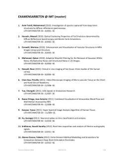


© Copyright 2026