
2D CAD for AutoCAD 2010-2012 on Windows
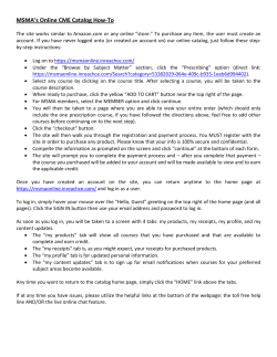
Standard Module - 2D Computer Aided Design ©ICS Skills 2014Quick Reference
This quick reference is for AutoCAD 2010 - 2012 on Windows
AutoCAD Opening Screen
Quick Access toolbar
Ribbon Panel
Info Center
Ribbon tab
Application
menu
Certification Test Goals
Ribbon
Navigation
bar
Cursor
Drawing
area
This module is aimed at second- and third-level students commencing study in fields related to the architectural, engineering,
and construction sectors, who wish to certify their 2D Computer
Aided Design (CAD) skills to an independent international standard. It is also suited to those who may work in these sectors
already in a non-technical capacity and who wish to acquire or
certify 2D CAD skills.
Successful candidates will be able to:
•• Use a two-dimensional design application to create and
save new drawings, import and export drawings.
•• Use layers and levels.
•• Create objects and elements, use selection tools, and
manipulate objects and elements.
•• Use inquiry commands, e.g. to measure distances,
angles, areas.
•• Set and modify properties; create and modify text and
dimensions.
•• Use blocks and cells; create, edit, and use objects from
a cell library; embed or link to objects using OLE.
•• Prepare outputs for printing or plotting.
UCS icon
Command
Line Window
Command
Prompt
Coordinate Readout
Home
Insert
Annotate
Parametric
View
Manage
Output
Status bar
Keyboard Shortcuts & Commands
Purpose
Keyboard
Shortcut
Command
Save the drawing.
CTRL+S
QSAVE
Display the Select File
dialog box.
CTRL+O
OPEN
Display the Plot dialog
box.
CTRL+P
PLOT
Switch to the next open
drawing.
CTRL+Tab
NONE
Switch to the previous/
next tab in the current
drawing.
CTRL+PgUp
/CTRL+PgDn
NONE
Display AutoCAD’s Help in
a Web browser window.
F1
HELP
Toggle the AutoCAD Text
Window on and off.
F2
TEXTSCR
Toggle running object
snap mode on and off.
F3
OSNAP
Toggle grid mode on
and off.
F7
GRID
Toggle ortho mode on
and off.
F8
ORTHO
Toggle snap mode on
and off.
F9
SNAP
Toggle polar mode on
and off.
F10
POLAR
Toggle object snap tracking on and off.
F11
NONE
Toggles dynamic input
mode on and off.
F12
DYNMODE
© 2012, ECDL Foundation. This Quick Reference may be used by candidates to assist in preparation for this ECDL module test. ECDL Foundation does not warrant that use of this guide will ensure passing of the test.
Autodesk screenshots reprinted with the permission of Autodesk, Inc. AutoCAD is a registered trademark or trademark of Autodesk, Inc, and/or its subsidiories and/or affiliates in the USA and other countries.
1
Getting Started
1.1
First Steps
1.1.1
Open a CAD application.
•• Click the Start button.
•• Select All Programs.
•• Click Autodesk.
•• Click AutoCAD LT or AutoCAD.
1.1.1
Close a CAD application.
•• Click the Application menu.
•• Click Exit AutoCAD LT or AutoCAD.
1.1.2
1.1.4
Set drawing units/working units: metric, imperial.
•• Click the Application menu.
•• Select Drawing Utilities and click Units.
Enter settings in the Drawing Units
dialog box.
•• Click on the Length Type drop-down
box and select a linear unit type.
•• Architectural uses feet and inches
with fractions.
•• Decimal uses decimal units that
can represent any linear unit of
measurement.
•• Engineering is the same as architectural but inches are displayed as
decimals rather than fractions.
•• Fractional is the same as architectural but there is no use of feet.
•• Scientific is the same as decimal
but displayed as scientific notation.
•• Click on the Angle Type drop-down
box and select an angular unit type.
•• Decimal where all angles are expressed as decimal degrees.
•• Deg/Min/Sec where angles are
expressed in degrees, minutes and
seconds.
•• Grads where one degree equals
1.11 grad.
•• Radians where one radian equals
57.3 degrees.
•• Surveyor units use bearings from
the north and south directions to
ward the east or west direction and
are expressed in degrees, minutes
and seconds.
•• Click OK.
1.1.6
1.1.6
Set, display snap/grid lock.
•• Right-click on the Grid Display tool in
the status bar and select Settings.
•• Check the Snap On check box.
•• Enter a value in the Snap X spacing box.
•• Enter a value in the Snap Y spacing box.
•• Click OK.
1.1.7
Create a drawing using an existing
specified template/seed file.
Use zoom/magnification tools.
Create a new drawing.
•• Click New in the Quick Access Toolbar.
•• Select a template from the list displayed.
•• Click Open.
1.1.5
1.2.1
Open one, several drawings.
•• Click Open on the Quick Access
Toolbar.
•• Select drawing(s) to open and click
Open.
1.1.3
1.2Navigating
Set drawing limits:
•• Enter LIMITS on the command line,
and press the Return key.
•• The lower left corner co-ordinates are
0,0 by default and should usually be
left at this setting.
•• Press the Return key, and enter coordinates for the upper right corner.
Set, display grid.
•• Right-click on the Grid Display tool in
the status bar, and select Settings.
•• Check the Grid On check box.
•• Enter a value in the Grid X spacing
box.
•• Enter a value in the Grid Y spacing
box.
•• Click OK.
••
••
••
••
Click the Application menu.
Click New and select Drawing.
Select a template from the list.
Click Open.
1.1.8
Save a drawing as a template/seed file.
•• Click the Application menu, and click
Save As.
•• Click the File Of Type drop-down list,
and select AutoCad LT Drawing Template (*.dwt)
•• Create a filename.
•• Click Save.
1.1.9
Save a drawing to a location on a drive.
•• Click the Application menu, and click
Save As.
•• Select the location.
•• Click Save.
1.1.10
Save a drawing under another name.
•• Click the Application menu, and click
Save As.
•• Enter a new file name over the existing
file name.
•• Click Save.
1.1.11
1.1.12
1.1.13
Hide built in toolbars.
•• On the View tab, in the Windows panel,
click the Toolbars button.
•• Click AutoCAD LT or AutoCad and
select to remove the check mark from
the toolbar.
1.2.2
Set/recall named/saved views.
•• On the View tab, in the Views panel,
click the View Manager button and
select a view from the Views list.
•• Click Set Current.
1.2.3
Use pan tool.
•• On the View tab, in the Navigate 2D
panel, click the Pan button. Press the
left mouse button, and drag around
the screen. This can also be achieved
by pressing the mouse wheel down
and dragging around the screen.
1.2.4
Use redraw, regen/update tools.
•• To redraw, enter R on the command
line, and press the Return key.
•• To regen, enter RE on the command
line, and press the Return key.
1.3
Using Layers/Levels
1.3.1
Create layers/levels and assign properties.
Close a drawing.
Use available Help functions.
•• Click on the Help button on the InfoCenter in the top right hand side of the
screen to open Autodesk Exchange for
the AutoCad website.
Create named/saved views.
•• On the View tab, in the Views panel,
click the View Manager button. Click
Current, and click the New button.
•• Click the Define window button, and
specify a selection window around the
area to be viewed.
•• Press the Return key.
•• Enter a view name, and click OK.
•• Click OK to close the View Manager
dialog box.
Display built in toolbars.
•• Click the Application menu.
•• Click Close.
1.1.14
1.2.2
Switch between open drawings.
•• Click the Quick View Drawings button
on the right side of the status bar.
•• Click the thumbnail of the drawing to
display it.
•• On the View tab, in the Windows panel,
click the Toolbars button.
•• Select AutoCAD LT or AutoCad and
select the toolbar required.
1.1.12
•• On the View tab, in the Navigate 2D
panel, click the zoom drop-down arrow button.
•• Click Extents to zoom to display the
maximum extents of all objects. This
can also be achieved by double clicking the mouse wheel.
•• Click Window to magnify an area on
the screen by picking two rectangular
points.
•• Click Object to magnify one or more
objects on the screen.
•• Click In or Out to magnify or shrink the
drawing. This can also be achieved by
pushing the mouse wheel forward or
backwards.
•• Click All to zoom to the limits of the
drawing area.
© 2012, ECDL Foundation. This Quick Reference may be used by candidates to assist in preparation for this ECDL module test. ECDL Foundation does not warrant that use of this guide will ensure passing of the test.
Autodesk screenshots reprinted with the permission of Autodesk, Inc. AutoCAD is a registered trademark or trademark of Autodesk, Inc, and/or its subsidiories and/or affiliates in the USA and other countries.
•• On the Home tab, in the Layers panel,
click the Layer Properties button.
•• Click the New layer button, and enter
a new name over Layer 1. Press the
Return key.
•• Assign property settings for Color,
Linetype, Lineweight.
1.4.1
Export a drawing in another file type: .pdf
•• Click the Application menu. Select
Export, and click PDF.
•• Enter a name and location for the
.pdf file. Click Save.
1.4.2
Import a dxf, dwg file into a drawing.
•• On the Insert tab, in the Block panel,
click the Insert button. Click the
Browse button.
•• Click the Files of type drop-down
list and select DXF (*.dxt) or select
Drawing (*.dwg).
•• Select a drawing to open, and click
Open.
2
Main Operations
1.3.2
Modify the properties/attributes of a layer/
level.
•• On the Home tab, in the Layers panel,
click the Layer Properties button.
•• Select a layer, and modify property settings for Color, Linetype, Lineweight.
1.3.3
1.3.4
1.4
Make a layer/level current or active.
•• On the Home tab, in the Layers panel,
click the Layer Properties button.
•• Select a layer, and click the green
tick at the top of the Layer Properties
dialog.
Modify levels/layers status: on, off, freeze, thaw, lock, unlock.
•• On the Home tab, in the Layers panel,
click the Layer Properties button and
select the layer to modify.
•• To turn on a layer, click the light bulb
on, and to turn off a layer, click the light
bulb off.
•• To freeze a layer, click the freeze icon
on, and to thaw a layer, click the freeze
icon off.
•• To allow the editing of objects in a
layer, click to open the lock icon, and
to not allow editing, click to close the
lock icon.
2.1
Create Objects/Elements
2.1.1
Apply co-ordinate systems: absolute, relative/rectangular, polar.
•• Absolute co-ordinates are positions
specified in units as a distance from
the origin 0,0.
•• To enter absolute co-ordinates enter
using the format X,Y.
•• Relative co-ordinates are positions
specified by a distance from the last
point input on the screen.
•• To enter relative co-ordinates enter
using the format @X,Y.
•• Polar co-ordinates are positions
specified by a distance and angle
from the last point input on the
screen and are entered using the
format @length in millimeters <angle
in degrees.
•• To draw a line 200mm long at an
angle of 35 , enter the polar coordinates @200<35
Drawing Exchange
1.4.1
Export a drawing in another file type: .dxf, .dwg
•• Click the Application menu, and click
Save As.
•• Click on the Files of type drop-down
list and select a *.dxf format or a *.dwg
format.
•• Select a folder, and click Save.
1.4.1
2.1.2
Export a drawing in another file type: .wmf
2.1.2
Draw a line.
•• On the Home tab, in the Draw panel,
click the Line button.
•• Select and click to start the line on
the screen, or enter co-ordinates
and click.
•• Select and click to specify the next
point of the line, or enter co-ordinates and click.
•• Press the Return key.
2.1.3
Draw a circle
•• On the Home tab, in the Draw panel,
click the Circle button.
•• Select Center, Radius to draw a
circle based on a center point and
a radius.
•• Select Center Diameter to draw a
circle based on a center point and
diameter.
•• Select 2 Points to draw a circle
based on two endpoints of a diameter.
•• Select 3 Points to draw a circle
based on three points on the circumference.
•• Select and click to draw a circle or
enter co-ordinates, and press the
Return key.
2.1.3
Draw an ellipse.
•• On the Home tab, in the Draw panel,
click the Ellipse button.
•• Select Center to create an ellipse
by using the center point of the
arc and the endpoint of the ellipse
axis.
•• Select Axis, End to create an
ellipse by defining a ratio between
the major and minor axis.
•• Select Elliptical Arc to create an
elliptical arc.
•• Select and click to draw an ellipse or
enter co-ordinates.
2.1.3
Draw a donut.
Draw a rectangle/block.
•• On the Home tab, in the Draw panel,
click the Rectangle button.
•• Select and click to draw a rectangle
or enter co-ordinates.
2.1.2
•• Click the Application menu. Select
Export, and click Other Formats.
•• Click on the Files of type drop-down
list, and select Metafile(*.wmf). Enter
a name and location for the .wmf file.
Click Save.
•• Select objects for export to the .wmf
file. Press the Return key.
1.4.1
Export a drawing in another file type: .dwf
•• Open the file for conversion to DWF.
•• On the Output tab, in the Plot panel,
click the Plot button. Click in the Name
drop-down list under Printer/plotter.
•• Select DWF6 ePlot.PC3 or DWFx ePlot
(XPS Compatible) .pc3. Click OK.
Select a location and enter a name for
the plot file. Click Save.
Draw a polyline/smartline.
•• On the Home tab, in the Draw panel,
click the Polyline button.
•• Select and click to draw each point
of a polyline or enter co-ordinates.
•• Press the Return key.
2.1.3
Draw an arc.
•• On the Home tab, in the Draw panel,
click the 3-point Arc button.
•• Select and click to draw a 3-point arc
or enter co-ordinates.
2.1.3
Draw a polygon.
•• On the Home tab, in the Draw panel,
click the Polygon button.
•• Enter the number of sides for the
polygon and specify the center of the
polygon.
•• Select Inscribed in Circle where
all vertices will fit inside a circle or
select Circumscribed about a Circle
where all the vertices are outside the
circle.
•• Specify a radius, and press the
Return key.
•• On the Home tab, in the Draw panel,
click the Draw arrow.
•• Click the Donut button.
•• Select and click to draw a donut or
enter co-ordinates.
2.1.4
Draw a spline/point curve.
•• On the Home tab, in the Draw panel,
click the Draw arrow.
•• Click the Spline Fit button.
•• Select and click to draw a spline or
enter co-ordinates.
•• Press the Return key.
2.1.5
Create a hatch.
•• On the Home tab, in the Draw panel,
click the Hatch button.
•• On the Hatch Creation tab, in the
Properties panel, set various hatch
properties as required.
© 2012, ECDL Foundation. This Quick Reference may be used by candidates to assist in preparation for this ECDL module test. ECDL Foundation does not warrant that use of this guide will ensure passing of the test.
Autodesk screenshots reprinted with the permission of Autodesk, Inc. AutoCAD is a registered trademark or trademark of Autodesk, Inc, and/or its subsidiories and/or affiliates in the USA and other countries.
2.1.6
Divide objects/points along an element.
•• On the Home tab, in the Draw panel,
click the Draw arrow.
•• Click the Divide button.
•• Click on the object to divide and enter
the number of segments.
•• Press the Return key.
2.1.7
Use snapping tools.
•• Right-click the Grid display tool in the
status bar. Click Settings. On the Snap
and Grid tab, enter the same spacing
setting in both the Snap X spacing box
and the Snap Y spacing box.
•• Check the Snap On (F9) check box.
•• Click OK.
2.2
Selection Tools
2.2.1
Select single, multiple objects.
•• On the Home tab, in the Modify panel,
click on any modify tool.
•• The mouse cursor becomes a Pickbox
cursor.
•• Click on object(s) to select them.
2.2.2
Use window selection tools.
•• To select objects that are fully within
a window, click to specify the top left
corner of the window and drag the
cursor across the objects for selection
and click.
•• To select objects that are fully within
a window and any objects that the
window crosses, click to specify the
bottom right corner of the window and
drag the cursor across the objects for
selection and click.
2.2.2
2.2.3
2.2.4
Use fence selection.
•• On the command line enter f, and
press the Return key. Draw a line
through the objects for selection.
•• Press the Return key.
Use grips/handles.
•• Click on an Object, and click a grip
point to open a menu that contains a
list of grip edit options.
Select by property/attribute, layer/level.
•• On the Home tab, in the Utilities panel,
click the Quick Select button to create
a selection set based on filtering criteria using the Quick Select dialog.
2.3
Manipulate Objects /Elements.
2.3.1
Copy objects/elements within drawings as objects/elements
•• On the Home tab, in the Modify panel,
click the Copy button.
•• Select the object or objects and press
the Return key.
•• Specify base point or displacement.
•• Select a base point if the exact
distance or angle to move a copy of
the objects or object is not known.
•• Specify displacement if the exact
distance or angle to move a copy of
the objects or object is known. Enter the required relative co-ordinate
without the @ sign.
•• After choosing a base point or
displacement, specify the distance
between the new copy of the object
and your original object.
•• Press the Return key.
2.3.1
2.3.1
Copy objects/elements between
drawings as objects/elements.
•• Select the object or objects.
•• On the Home tab, in the Clipboard
panel, click the Copy Clip button.
•• Open and click in the other drawing.
•• On the Home tab, in the Clipboard
panel, click the Paste button.
•• Select and click to specify the insertion
point or enter co-ordinates.
•• Press the Return key.
Copy objects/elements within drawings as a block.
•• On the Home tab, in the Modify panel,
click the Copy button.
•• Select the block and press the Return
key.
•• Specify base point or displacement.
•• Select a base point if the exact
distance or angle to move a copy
of the block is not known.
•• Specify displacement if the exact
distance or angle to move a copy
of the block is known. Enter the required relative co-ordinate without
the @ sign.
•• After choosing a base point or
displacement, specify the distance
between the new copy of the block
and your original object. Press the
Return key.
2.3.2
Move objects/elements within a drawing.
•• On the Home tab, in the Modify panel,
click the Move button.
•• Select the object or objects and press
the Return key.
•• Specify base point or displacement.
•• Select a base point if the exact distance or angle to move the objects
or object is not known.
•• Specify displacement if the exact
distance or angle to move the
objects or object is known. Enter
the required relative co-ordinate
without the @ sign.
•• After choosing a base point or displacement, specify the distance to the
new position for the selected object.
•• Press the Return key.
2.3.7
Stretch objects/elements.
•• On the Home tab, in the Modify
panel, click the Stretch button.
•• Use a crossing window to select the
object.
•• Press the Return key.
•• Select and click to Specify base
point or enter co-ordinates.
•• Press the Return key.
•• Select and click to Specify Second
point or enter co-ordinates.
•• Press the Return key.
2.3.8
Offset/copy parallel objects/elements.
•• On the Home tab, in the Modify
panel, click the Offset button.
•• Select and click to specify the
offset distance between the original
object and the new object or enter a
distance.
•• Select the object.
•• Press the Return key.
•• Specify point on side to offset by
clicking on the side of the object
where the copy will be placed.
•• Press the Return key.
2.3.9
Create arrays/patterns of objects/
elements.
2.3.2
Move objects/elements between
drawings.
•• Select the object or objects.
•• On the Home tab, in the Clipboard
panel, click the Cut button.
•• Open and click in the other drawing.
•• On the Home tab, in the Clipboard
panel, click the Paste button.
•• Select and click to specify the insertion point or enter co-ordinates.
•• Press the Return key.
2.3.3
Delete objects/elements.
•• Select the objects.
•• Press the Delete key.
2.3.4
Rotate objects/elements.
•• On the Home tab, in the Modify panel,
click the Rotate button.
•• Select the object.
•• Press the Return key.
•• Select and click to Specify base point
or enter co-ordinates.
•• Press the Return key.
•• Rotate cursor and click to Specify
rotation angle or enter angle.
2.3.5
Scale objects/elements.
•• On the Home tab, in the Modify panel,
click the Scale button.
•• Select the object and press the Return
key.
•• Select and click to Specify base point
or enter co-ordinates.
•• Press the Return key.
•• Click to Specify scale factor or enter a
scale factor and click.
2.3.6
Mirror objects/elements.
•• On the Home tab, in the Modify panel,
click the Mirror button.
•• Select the object and press the Return
key.
•• Select and click to Specify first point
of mirror line or enter co-ordinates
and click.
•• Select and click to Specify second
point of mirror line or enter coordinates.
•• Press the Return key.
•• Enter N to prompt Erase source
objects?
•• To create a rectangular array, click on
the Home tab. In the Modify panel,
click the Array button arrow, and
click Rectangular Array.
•• Select the objects to array.
•• Press the Return key.
•• Select and click to specify a point for
the opposite corner of the grid to set
the number of rows and columns.
•• A preview grid displays.
•• Select and click to specify a point for
the opposite corner of the grid to set
the row and column spacing. Press
the Return key.
2.3.9
Create arrays/patterns of objects/
elements.
•• To create a polar array click on the
Home tab. In the Modify panel.
•• Click the Array button arrow, and
click Polar Array.
•• Select the objects to array, and press
the Return key.
•• Specify a center point or a base
point or enter an axis of rotation,
and specify two points to define a
custom axis of rotation.
•• Specify the number of items.
•• Specify the angle to fill.
•• Press the Return key.
2.3.10
Trim objects using other objects/
elements.
•• On the Home tab, in the Modify
panel, click the Trim button.
•• Select cutting edges by clicking
on the object to trim to. Press the
Return key.
•• Click on the object to trim.
2.3.11
Break/partially delete objects.
•• On the Home tab, in the Modify panel,
click the Modify arrow.
•• Click the Break button.
•• Select two points on the object.
2.3.12
2.3.13
Explode/drop objects/elements.
•• On the Home tab, in the Modify panel,
click the Explode button.
•• Select the object to explode.
•• Press the Return key.
Extend, lengthen objects/elements.
•• On the Home tab, in the Modify panel,
click the Extend button.
•• Select the objects to serve as boundary
edges.
•• Press the Return key.
•• Select the objects to extend.
2.3.14
Apply chamfers.
•• On the Home tab, in the Modify panel,
click the Chamfer button.
•• Enter d (Distances).
•• Enter the first chamfer distance and
press the Return key.
•• Enter the second chamfer distance and
press the Return key.
•• Select the objects to chamfer.
2.3.15
Apply fillets.
•• On the Home tab, in the Modify panel,
click the Fillet button.
•• Enter r (Radius) and press the Return
key.
•• Enter the fillet radius, and press the
Return key.
•• Select the objects to fillet.
2.3.16
2.3.17
Using Inquiry Commands
2.4.1
Measure distances.
•• On the Home tab, in the Utilities panel,
click the Measure arrow.
•• Click Distance.
•• Select two points on the object to
measure.
•• Press the Return key.
Measure angles.
•• On the Home tab, in the Utilities panel,
click the Measure arrow. Click Angle.
•• Select the first line.
•• Select the second line and press the
Return key.
2.6.3
Change style, font for text objects.
•• Select and right-click on the text
object. Click Edit.
•• Click on the Style box to select a
style.
•• Click on the Font box to select a
font.
•• Click OK.
2.6.4
Add dimensions.
•• On the Annotate tab, in the Dimensions panel, click the Dimensions
button arrow.
•• Select a dimension type.
2.6.5
Create, set, dimension styles.
•• On the Annotate tab, in the Dimensions panel, click the Dimensions
arrow.
•• Click the New Button.
•• Enter a new style name.
•• Click on the Start With drop-down
box and select a style to use as a
basis for the new style. For the new
style, you change only the properties
that differ from the properties you
start with.
•• Click on the Use for drop-down box
and select All dimensions if the style
will be used for all dimensions, or select Specified dimensions if the style
will be used for specific dimensions.
•• Click the Continue button to define
properties as required.
•• Click OK.
2.6.5
Edit dimension styles.
•• On the Annotate tab, in the Dimensions panel, click the Dimensions
arrow.
•• Click the Modify Button to modify
properties as required.
•• Click OK.
2.6.6
Change style for dimension objects.
•• On the Annotate tab, in the Dimensions panel, click the Dimensions
arrow.
•• Choose a style from the Styles box,
and click the Set Current button.
•• Click Close.
2.6.6
Change font for dimension objects.
•• On the Annotate tab, in the Dimensions panel, click the Dimensions
arrow.
•• Click the Modify button.
•• On the Text tab. Click the Text Style
button.
•• Select the font, size and style as
required.
2.6.7
Insert geometric tolerance.
2.5Properties.
2.5.1
Change layer/level properties/attributes of objects/elements.
•• Select the objects.
•• On the Home tab, in the Layers
panel, click Layer Properties.
•• In the Layer Properties Manager, select the layer to assign to the objects.
2.5.2
Match properties/attributes between objects/elements.
•• On the Home tab, in the Clipboard
panel, click Match Properties.
•• Select the objects that have the
properties to be copied.
•• Enter s in the command line, and
press the Return key. Click to remove
any properties in the Property Settings box that are not to be copied.
Click OK.
•• Select the objects to which to apply
the selected properties, and press
the Return key.
2.5.3
Set, change linetype/linestyle, line weight, colour of objects/elements.
•• Select the objects.
•• On the Home tab, in the Properties
panel, click Properties.
•• Set or change the object properties.
2.6
Annotation (text and dimensions)
2.6.1
Insert text.
Convert objects/elements to polylines/
complex elements
•• On the Home tab, in the Modify panel,
click the Edit Polyline button.
•• Select the object.
•• Accept Y when prompted.
•• Press the Return key.
2.4
2.4.1
Measure areas.
•• On the Home tab, in the Utilities
panel, click the Measure arrow.
•• Click Area.
•• Select the area to measure, and
press the Return key.
Edit polylines/complex elements.
•• On the Home tab, in the Modify panel,
click the Modify arrow. Click the Edit
Polyline button.
•• Select the polyline.
•• Select an option to edit.
2.4.2
•• On the Home tab, in the Annotation
panel, click the Text arrow.
•• Click Single Line.
•• Select and click or enter co-ordinates to specify the insertion point
for the first character.
•• Specify the height of the text. A
rubber-band line is attached from
the text insertion point to the cursor.
Click to set the height of the text to
the length of the rubber-band line.
•• Enter a text rotation angle.
•• Enter the text, and at the end of each
line press the Return key.
•• Press the Return key on a blank line
to finish.
2.6.1
Edit Text
•• Double click on the text and edit it.
2.6.2
Create, set, text styles.
•• On the Annotate tab, in the Text
panel, click the Text arrow.
•• Click the New button.
•• Enter a style name, and click OK.
•• Click the Font Name drop-down box
and select a font.
•• Click the Annotative box in the Size
group.
•• Enter a height in the Paper Text
Height box.
•• Click the Set Current button.
•• Click Apply, and click Close.
2.6.2
Edit text styles.
•• On the Annotate tab, in the Text
panel, click the Text arrow.
•• Select a style from Styles and make
changes to the Font, Size or Effects.
•• Click Apply, and click Close.
•• On the Annotate tab, in the Dimensions panel, click the Dimensions
arrow and click the Tolerance button.
•• Click on the black boxes under
each section to bring up the Symbol
dialog box or the Material Condition
dialog box.
•• Select the required symbols.
•• Click OK.
•• Select a point on the screen to place
the tolerance symbols.
3
Advanced Features
3.1
Using Blocks/Cells
3.1.1
Create blocks/cells.
•• On the Home tab, in the Block panel,
click the Create button.
•• Enter a block name, select the objects, and specify an insertion point.
3.1.2
Insert blocks/cells in a drawing.
•• On the Home tab, in the Block panel,
click the Insert button.
•• In the Name box, select the block
required.
•• To pick an insertion point and set
scale and rotation on the screen,
check the Specify On-screen check
box, or leave the box unchecked and
enter the values.
•• To insert the objects in the block as individual objects instead of as a single
block, select Explode.
•• Click OK
3.1.3
Create a wblock.
•• Enter wblock on the command line,
and press the Return key.
•• Block - Click the Block button to
specify an existing block to save as a
file by selecting a block from the list
•• Entire drawing - Click the Entire
drawing button to select the current
drawing to save as a file
•• Objects - Click the Objects button to
select objects to save as a file by first
entering the base point co-ordinates
and then selecting the objects
•• Select the Insert units, and enter the
file name and path for the file.
•• Click OK.
3.1.4
Create a cell library.
•• Cell Library is not available in AutoCAD.
3.1.5
Create attributes/tags.
3.2.1
Link a file and display as an object.
•• On the Insert tab, in the Data panel, click
the OLE Object button.
•• Click Create from File, and click browse
to select the location and name of the
file.
•• Check the Link check box.
3.2.2
Add a hyperlink to an object.
•• Select the object to be linked.
•• On the Insert tab, in the Data panel, click
the Hyperlink button.
•• Create a hyperlink to an existing file or
webpage.
4
Outputs
4.1
Plot/Print Options
4.1.1
Use model space, paper space/design model, sheet model.
•• Click the Model tab to access the model
space.
•• Click Layout 1 and Layout 2 to access
the paper space.
4.1.2
Create, use, layouts/sheet models.
•• Right-click on any of the existing Layout
tabs.
•• Click New layout or click From template
to create a layout based on a template.
4.1.2
Modify layouts/sheet models.
•• Right-click on the Layout tab to modify.
•• Click Delete to delete the layout.
•• Click Move or Copy to move or copy the
selected layout.
•• Click Select All layouts to select all the
layouts.
•• Click Page Setup to modify the page
setup.
•• Click Plot to plot the layout.
4.1.3
•• On the Home tab, in the Block panel,
click the Block button arrow.
•• Click Define Attributes.
•• Enter a name for the attributes tag in
the tag box.
•• Enter text in the Prompt box.
•• Enter a default value in the Default
box.
•• Click on one or more Mode options for
the attribute value.
•• To specify the insertion point onscreen, check the Specify onscreen check box, or leave the box
unchecked, and enter co-ordinates to
position the attributes.
•• Enter text height and rotation.
•• Click OK.
3.1.5
Edit attributes/tags.
•• On the Home tab, in the Block panel,
click the Single button arrow, and click
Single.
•• On the Attribute tab, click on a tag and
edit its value.
•• Click Apply.
•• Click OK.
3.1.6
Insert objects/elements, files from a library.
•• On the Insert tab, in the Block panel,
click the Insert button.
•• Enter or browse for the block name.
•• To specify the insertion point
on-screen, check the Specify onscreen check box, or leave the box
unchecked and enter co-ordinates to
position the block or drawing to insert.
3.1.7
Extract/report, attributes/tags from a block/cell e.g.to create a parts list.
•• Enter ATTexT on the command line
and press the Return key.
•• Specify an extraction type.
3.2
Using OLE
3.2.1
Embed a file and display as an object.
•• On the Insert tab, in the Data panel,
click the OLE Object button.
•• Click Create from File and browse to
select the location and name of the
file.
Create different viewports/views.
•• On the View tab, in the Viewports panel,
click the Rectangular button.
•• Select the bottom left hand corner and
click.
•• Select the top right hand corner and
click.
4.1.3
Scale different viewports/views.
•• In paper space, select the viewport to
scale.
•• On the status bar, click the Model or
Paper space button to display Model.
•• On the status bar click the Viewport
Scale button, and select a scale value
from the list.
4.1.4
Add a titleblock.(model space)
•• On the Insert tab, in the Block panel,
click the Insert button.
•• Specify the name of the block to insert or
click Browse to browse for the block.
•• Specify the insertion point for the block.
•• Specify the scale of the inserted block.
•• Click OK.
4.1.4
Add a titleblock. (paper space)
•• On the Insert tab, in the Block panel,
click the Insert button.
•• Specify the Name of the block to insert,
or click Browse to browse for the block.
•• Check the Specify On-screen check box
to pick an insertion point on the screen.
•• Leave the Specify On-screen checkbox
unchecked for Scale. Enter 1 in the X
box.
•• Click OK.
•• Place the titleblock inside the dashed
line.
4.1.5
Select a printer/plotter.
•• On the Output tab, in the Plot panel, click
the Plot button.
•• Select a printer or plotter, and specify
page setup details.
4.1.6
Add and use a plot style/pen table.
•• On the Output tab, in the Plot panel,
click the Plot button.
•• Click the More Options arrow on bottom right of dialog box to display more
options in this dialog.
•• Plot style table (pen assignments)
displays the plot style table that is
assigned to the current model tab or
layout tab. Click to display a list of the
currently available plot style tables.
4.1.7
Plot/print all, part of a drawing to scale, fit to page.
•• On the Output tab, in the Plot panel,
click the Plot button.
•• Click the What to Plot drop-down box.
•• Select Display to plot the current
display.
•• Select Extents to fill the sheet with
all visible objects in the drawing for
plotting.
•• Select Limits to plot that portion of
the current space of the drawing
that contains objects.
•• Select Window to make a window
around the area to plot.
•• Check the Fit to paper checkbox to let
AutoCAD work out the scale or enter a
custom scale.
•• Click OK.
For more information, visit:
www.ecdl.org
© 2012, ECDL Foundation. This Quick Reference may be used by candidates to assist in preparation for this ECDL module test. ECDL Foundation does not warrant that use of this guide will ensure passing of the test.
Autodesk screenshots reprinted with the permission of Autodesk, Inc. AutoCAD is a registered trademark or trademark of Autodesk, Inc, and/or its subsidiories and/or affiliates in the USA and other countries.


© Copyright 2026