
Installation, Start-Up and Service Instructions
39MN03-61 and 39MW03-30
Indoor and Weathertight Outdoor
Air Handlers
Installation, Start-Up and
Service Instructions
CONTENTS
Page
INTRODUCTION . . . . . . . . . . . . . . . . . . . . . . . . . . . . . . . . . . . . .1
SAFETY CONSIDERATIONS . . . . . . . . . . . . . . . . . . . . . . . . .2
UNIT AND COMPONENT IDENTIFICATION . . . . . . . . . 2-8
PRE-INSTALLATION . . . . . . . . . . . . . . . . . . . . . . . . . . . . . . 8-36
Inspection . . . . . . . . . . . . . . . . . . . . . . . . . . . . . . . . . . . . . . . . . . .8
Rigging and Handling . . . . . . . . . . . . . . . . . . . . . . . . . . . . . . .8
Long-Term Storage . . . . . . . . . . . . . . . . . . . . . . . . . . . . . . . . .33
Service Clearance . . . . . . . . . . . . . . . . . . . . . . . . . . . . . . . . . .33
Drain Positioning . . . . . . . . . . . . . . . . . . . . . . . . . . . . . . . . . . .33
Unit Suspension. . . . . . . . . . . . . . . . . . . . . . . . . . . . . . . . . . . .33
Internal Vibration Isolation . . . . . . . . . . . . . . . . . . . . . . . . .33
External Vibration Isolation. . . . . . . . . . . . . . . . . . . . . . . . .34
Roof Curb . . . . . . . . . . . . . . . . . . . . . . . . . . . . . . . . . . . . . . . . . .34
Pier or Beam Mount . . . . . . . . . . . . . . . . . . . . . . . . . . . . . . . .36
INSTALLATION . . . . . . . . . . . . . . . . . . . . . . . . . . . . . . . . . . 37-73
Unit/Section Connection. . . . . . . . . . . . . . . . . . . . . . . . . . . .37
Mixing Box . . . . . . . . . . . . . . . . . . . . . . . . . . . . . . . . . . . . . . . . .38
Zone Damper Section . . . . . . . . . . . . . . . . . . . . . . . . . . . . . .38
Face and Bypass Dampers . . . . . . . . . . . . . . . . . . . . . . . . .39
Mixing Box/Filter Mixing Box Damper Linkage. . . . . .41
Mixing Box Damper Actuators . . . . . . . . . . . . . . . . . . . . . .41
Vertical Draw-Thru Units. . . . . . . . . . . . . . . . . . . . . . . . . . . .43
Fan Motors and Drives . . . . . . . . . . . . . . . . . . . . . . . . . . . . .44
Sheaves . . . . . . . . . . . . . . . . . . . . . . . . . . . . . . . . . . . . . . . . . . . .45
V-Belts. . . . . . . . . . . . . . . . . . . . . . . . . . . . . . . . . . . . . . . . . . . . . .46
Plenum Fan Duct Connections . . . . . . . . . . . . . . . . . . . . .46
Fan Discharge Connections . . . . . . . . . . . . . . . . . . . . . . . .46
Panel Cutting . . . . . . . . . . . . . . . . . . . . . . . . . . . . . . . . . . . . . . .46
Outdoor Hoods and Louvers . . . . . . . . . . . . . . . . . . . . . . .48
Coil Connection Housing . . . . . . . . . . . . . . . . . . . . . . . . . . .49
Water and Steam Coil Piping
Recommendations . . . . . . . . . . . . . . . . . . . . . . . . . . . . . . .52
Coil Freeze-Up Protection . . . . . . . . . . . . . . . . . . . . . . . . . .52
Refrigerant Piping, Direct-Expansion Coils . . . . . . . . .55
Hot Gas Piping and Wiring . . . . . . . . . . . . . . . . . . . . . . . . .59
• INSTALL PIPING
Condensate Drain . . . . . . . . . . . . . . . . . . . . . . . . . . . . . . . . . .60
Fan Motor Wiring Recommendations . . . . . . . . . . . . . . .60
• FAN MOTOR STARTER
• DISCONNECT
• VFD
• VFD WITH BYPASS
Electric Heaters . . . . . . . . . . . . . . . . . . . . . . . . . . . . . . . . . . . .67
Energy Recovery Ventilation Sections . . . . . . . . . . . . . .72
• RECEIVING AND INSPECTION
• RIGGING AND STACKING
• ERV WHEEL MOTOR WIRING
Page
START-UP . . . . . . . . . . . . . . . . . . . . . . . . . . . . . . . . . . . . . . . 73-75
Checklist . . . . . . . . . . . . . . . . . . . . . . . . . . . . . . . . . . . . . . . . . . . 73
Energy Recovery Wheel . . . . . . . . . . . . . . . . . . . . . . . . . . . . 75
SERVICE . . . . . . . . . . . . . . . . . . . . . . . . . . . . . . . . . . . . . . . . 75-95
General . . . . . . . . . . . . . . . . . . . . . . . . . . . . . . . . . . . . . . . . . . . . 75
Electric Heaters . . . . . . . . . . . . . . . . . . . . . . . . . . . . . . . . . . . . 75
Fan Motor Replacement . . . . . . . . . . . . . . . . . . . . . . . . . . . . 75
Energy Recovery Ventilation . . . . . . . . . . . . . . . . . . . . . . . 75
•
•
•
•
•
CLEANING
CASSETTE REPLACEMENT
ADJUSTING AIR SEALS
SEGMENT INSTALLATION AND REPLACEMENT
WHEEL DRIVE MOTOR AND PULLEY
REPLACEMENT
• BELT REPLACEMENT
• OTHER MAINTENANCE
Cleaning Unit Interior/Exterior. . . . . . . . . . . . . . . . . . . . . . 78
Coil Cleaning. . . . . . . . . . . . . . . . . . . . . . . . . . . . . . . . . . . . . . . 78
Winter Shutdown. . . . . . . . . . . . . . . . . . . . . . . . . . . . . . . . . . . 79
Coil Removal . . . . . . . . . . . . . . . . . . . . . . . . . . . . . . . . . . . . . . . 79
Changing Coil Hand . . . . . . . . . . . . . . . . . . . . . . . . . . . . . . . . 80
Filters . . . . . . . . . . . . . . . . . . . . . . . . . . . . . . . . . . . . . . . . . . . . . . 81
Fan Shaft Bearing Removal . . . . . . . . . . . . . . . . . . . . . . . . 94
Fan and Shaft Removal. . . . . . . . . . . . . . . . . . . . . . . . . . . . . 94
Motor Location . . . . . . . . . . . . . . . . . . . . . . . . . . . . . . . . . . . . . 94
Lubrication . . . . . . . . . . . . . . . . . . . . . . . . . . . . . . . . . . . . . . . . . 95
Motor and Drive Package Data . . . . . . . . . . . . . . . . . . . . . 95
TROUBLESHOOTING. . . . . . . . . . . . . . . . . . . . . . . . . . . . 95,96
Steam Coil Performance Problems . . . . . . . . . . . . . . . . . 95
Steam Failure Modes . . . . . . . . . . . . . . . . . . . . . . . . . . . . . . . 95
METRIC CONVERSION CHART . . . . . . . . . . . . . . . . . . . . . 97
INTRODUCTION
The 39M series central station air handlers are usually
installed with ductwork; they provide air conditioning at
nominal capacities of 1500 to 30,500 cfm. The 39M air handler
(see Fig. 1) has a design that allows hundreds of different
configuration possibilities. Each unit is assembled to meet
specific job requirements and can be shipped in sections or as a
single assembly. These instructions describe how to install,
start up, and service 39M air handlers.
Manufacturer reserves the right to discontinue, or change at any time, specifications or designs without notice and without incurring obligations.
PC 201
Catalog No. 533-944
Printed in U.S.A.
Form 39M-4SI
Pg 1
12-03
Replaces: 39M-2SI
Book 3
Tab 1b
SAFETY CONSIDERATIONS
39M air-handling equipment (see Fig. 1) is designed to
provide safe and reliable service when installed and operated
within design specifications. To avoid injury to personnel and
damage to equipment or property when operating this equipment, use good judgment and follow safe practices as outlined
below.
SECURE fan drive sheave with a rope or strap before
working on a fan to ensure that rotor cannot freewheel.
DO NOT restore power to unit until all temporary walkways inside components have been removed.
NEVER pressurize equipment in excess of specified test
pressures.
PROTECT adjacent flammable material when welding or
flame cutting. Have a fire extinguisher at hand and ready
for immediate use.
PREVENT unauthorized entry into the unit; leave safety
latches in place on access doors except during installation
or service procedures. After accessing a section, replace
and tighten the safety latch.
FIELD SUPPLIED MOTORS should be Underwriters’
Laboratories (UL) or Canadian Standards Association
(CSA) approved.
FIELD WIRING must comply with National Electrical
Code (NEC) and all local requirements.
DO NOT ground equipment to fan assembly when welding. Damage to fan bearings could result.
NEVER enter an enclosed fan cabinet or reach into a unit
while the fan is running.
LOCK OPEN AND TAG the fan motor power disconnect
switch before working on a fan. Take fuses with you and
note removal on tag.
LOCK OPEN AND TAG the electric heat coil power disconnect switch before working on or near heaters.
CHECK the assembly and component weights to be sure
that the rigging equipment can handle them safely.
Note also the centers of gravity and any specific rigging
instructions.
CHECK for adequate ventilation so that fumes will not
migrate through ductwork to occupied spaces when welding or cutting inside air-handling unit cabinet or plenum.
WHEN STEAM CLEANING COILS be sure that the area
is clear of personnel.
DO NOT remove access panel fasteners until fan is completely stopped.
Pressure developed by a moving fan can cause excessive
force against the panel and toward personnel.
DO NOT work on dampers until their operators are
disconnected.
BE SURE that fans are properly grounded before working
on them.
UNIT AND COMPONENT IDENTIFICATION
The 39M comes in two basic configurations; horizontal and
vertical. Using appropriate sections, it is possible to design
many unit variations, including blow-thru units and plenum fan
units with multiple discharges. Fig. 2A-2F show an example of
the model number used for 39M unit sections and components.
Each unit’s model number is listed on a label affixed to the fan
section. Section and major component level part numbers are
listed and affixed to each individual component section.
For further information on unit and component identification refer to Table 1, Fig. 3A-3B and contact your Carrier
representative for the AHUBuilder® program. Refer to the
39M Product Data catalog for more information on individual
component sections.
Fig. 1 — Typical 39M Air Handler (Indoor Unit Shown)
2
39M
N
03
-
000001
12
S
X
Product Type
39M
S
Shipping Option
S – Standard
Q – Quick Ship
Always X
Code Model
N – Indoor Unit
W – Outdoor Unit
Unit Crating Option
S – Skid only
C – Protective cover skid
B – Export with protective cover
E – Export without protective cover
Unit Size
03
06
08
10
12
14
17
21
25
30
36
40
50
61
Shipping No. of Pieces
Example: 12 = 1 of 2
22 = 2 of 2
000001 thru 999999 – Standard Unit
Revision Level
Fig. 2A — 39M Unit Nomenclature
28MC V 6 20 F D A 020 A R N X
X – Always
Model Number
28MC – 1/2" Chilled Water
28MH – 1/2" Hot Water
Coating
N – Non-Coated
E – E-Coated
Coil Position
H – Horizontal
V – Vertical
Rows
1 –
2 –
4 –
6 –
8 –
0 –
Hand
R – Righthand
L – Lefthand
1 Row
2 Row
4 Row
6 Row
8 Row
10 Row
Header Style
A – MPT Std
B – MPT-Non Ferrous
NOTE: If positions 7-8 are ≥ 30,
then position 15 cannot = B.
Tubes In Face 12 - 44
Unit
Size L
M
B S
03
20
14 12 N/A
06
20
14 12 12
08
22
16 14 12
10
22
16 14 12
12
28
22 20 14
14
28
24 20 14
17
30
24 22 16
21
38
32 28 18
25
38
32 28 18
30
38
32 28 18
36
44
36 30 24
40 24/24 44 36 24
50 28/28 44 36 28
61 34/34 28/28 44 34
Unit
Size DBTS* (in.)
03
020
21
065
06
034
25
074
08
040
30
092
10
052
36
096
12
052
40
096
14
059
50
104
17
065
61
104
* Distance between tube sheets.
Tube Wall and
Hairpin Type
1/2" O.D. Copper Tube
A – .016 Std. Hairpin
B – .025 Std. Hairpin
Circuiting
H – Half Circuit
F – Full Circuit
D – Double Circuit
B
D
F
H
L
M
S
Fin Material
Fins Per Inch
Casing Material
A – AL 8 GALV.
D – AL 11 GALV.
F – AL 14 GALV.
G – AL 8 ST. STL.
K – AL 11 ST. STL.
M – AL 14 ST. STL.
N – CU 8 ST. STL.
R – CU 11 ST. STL.
T – CU 14 ST. STL.
LEGEND
— Bypass
— Double Circuit
— Full Circuit
— Half Circuit
— Large
— Medium
— Small
Fig. 2B — 28MC,28MH (1/2-in. Water Coil) Nomenclature
3
28MZ H 1 26 F B S 034 A X N –
Model Number
28MZ – IDT Steam
Coil Revision
(-)
Coil Position
H – Horizontal
V – Vertical
Coating
N – Non-Coated
E – E-Coated
X – Always
Rows
1 – 1 Row
2 – 2 Row
(Pos. 11 Must =T)
Header Style
A – MPT Std
Header Note:
Pos. 11 (Type 'S')
Supply = 2 1/2" MPT
Condensate = 2 1/2" MPT
Pos. 11 (Type 'T')
(1) Row 10-28TF = 2" MPT (Supply & Return)
29-40 = 2 1/2" MPT (Supply)
= 2" MPT (Return)
(2) Row 10-28TF = 2 1/2" MPT (Supply & Return)
29-40TF = 3" MPT (Supply)
= 2 1/2" MPT (Return)
TF-Tubes in face
Tubes In Face*
If position 11 = S
If position 11 = T
Unit
1 IN.
5/8 IN.
Size L
M B S
L
M
B S
03
8
5
5 N/A
16
10 10 N/A
06
8
5
5 5
16
10 10 10
08
9
6
5 5
18
12 11 10
10
9
6
5 5
18
12 11 10
12 11
9
8 5
22
18 16 10
14 11
10 8 5
22
20 16 10
17 12
10 9 6
24
20 19 12
21 15
13 11 7
30
26 22 14
25 15
13 11 7
30
26 22 14
30 15
13 11 7
30
26 22 14
36 18
15 12 10
36
30 24 20
40 10/10 18 15 10 20/20
36 30 20
50 12/11 18 15 11 24/22
36 30 22
61 14/14 12/11 18 14 28/28 24/22 36 28
*Multiple values indicate that two coils must be ordered.
Unit
Size
DBTS† (in.)
03
020
06
034
08
040
10
052
12
052
14
059
17
065
21
065
25
074
30
092
36
096
40
096
50
104
61
104
† Distance between tube sheets.
Circuiting
F – Full
Fin Material
Fins Per Inch
Casing Material
B – AL 6 GALV.
E – AL 9 GALV.
C – AL 12 GALV.
H – AL 6 ST. STL.
L – AL 9 ST. STL.
J – AL 12 ST. STL.
P – CU 6 ST. STL.
S – CU 9 ST. STL.
Q – CU 12 ST. STL.
Tube Size and Copper Wall
S – 1" O.D. x .030 Wall Outer Tube
5/8" O.D. x .020 Wall Inner Tube
(Aerofin HM)
T – 5/8" O.D. x .035 Wall Outer Tube
3/8" O.D. x .020 Wall Inner Tube
(Aerofin HD)
Fig. 2C — 28MZ (Steam Coil) Nomenclature
4
28ME V 4 32 B A A 065 Z R N X
Model Number
28ME – Direct Expansion
X – Always
Coil Position
V – Vertical
Coating
N – Non-Coated
E – E-Coated
Rows
4 – 4 Row
6 – 6 Row
8 – 8 Row
Hand
R – Righthand
L – Lefthand
Header Style
Z – Standard (Copper)
Varies with Coil
Tubes In Face 14 - 44
Unit
Size
L
M
03
20
14
06
20
14
08
22
16
10
22
16
12
28
22
14
28
24
17
30
24
21
38
32
25
38
32
30
38
32
36
44
36
40
24/24
44
50
28/28
44
61
34/34 28/28
Unit
Size
03
06
08
10
12
14
17
21
25
30
36
40
50
61
Circuiting
A – Face Split Quarter
B – Face Split Half
C – Face Split Full
D – Double
E – Quarter Circuit - Single Distributor
J – Half Circuit - Single Distributor
G – Row Split Full
K – Row Split Quarter
M – Row Split Half
DBTS* (in.)
020
034
040
052
052
059
065
065
072
092
096
096
104
104
* Distance between tube sheets.
Tube Wall and Hairpin Type
1/2" O.D. Copper Tube
A – .016 Std. Hairpin
B – .025 Std. Hairpin
Fin Material
Fins Per Inch
Casing Material
A – AL 8 GALV.
D – AL 11 GALV.
F – AL 14 GALV.
G – AL 8 ST. STL.
K – AL 11 ST. STL.
M – AL 14 ST. STL.
N – CU 8 ST. STL.
R – CU 11 ST. STL.
T – CU 14 ST. STL.
Fig. 2D — 28ME (Direct Expansion Coil) Nomenclature
5
28MD V 4 30 F A C 092 A R N A
A – Always
Model Number
28MD – 5/8" Chilled Water
28MJ – 5/8" Hot Water
Coating
N – Non-Coated
E – E-Coated
Coil Position
H – Horizontal
V – Vertical
Rows
1 –
2 –
4 –
6 –
8 –
Hand
R – Righthand
L – Lefthand
1 Row
2 Row
8 Row
6 Row
8 Row
Header Style
A – MPT Standard
B – MPT-Non Ferrous
Tubes In Face
10 - 36
Unit
Size
03
06
08
10
12
14
17
21
25
30
36
40
50
61
Circuiting
H – Half Circuit
F – Full Circuit
D – Double Circuit
Fin Material
Fins Per Inch
Casing Material
A – AL 8 GALV.
C – AL 12 GALV.
F – AL 14 GALV.
G – AL 8 ST. STL.
J – AL 12 ST. STL.
M – AL 14 ST. STL.
N – CU 8 ST. STL.
Q – CU 12 ST. STL.
T – CU 14 ST. STL.
DBTS* (in.)
020
034
040
052
052
059
065
065
074
092
096
096
104
104
*Distance between tube sheets.
Tube Wall and Hairpin Type
5/8" O.D. Copper Tube
C – .020 Std. Hairpin
D – .035 Std. Hairpin
Fig. 2E — 28MD,28MJ (5/8-in. Water Coil) Nomenclature
6
93 MR 01 18 B A 02 0 1 0 3 S Fan Motor
Revision Level
MR – High Efficiency
MS – Premium Efficiency
Horsepower
01 – 1/2
02 – 3/4
03 – 1
04 – 1 1/2
05 – 2
06 – 3
07 – 5
08 – 7 1/2
09 – 10
10 – 15
11 – 20
12
13
14
15
16
17
18
19
20
21
–
–
–
–
–
–
–
–
–
–
Fan Application
R – Return/Exhaust
S – Supply
25
30
40
50
60
75
100
125
150
200
Supplier Designation
Not Used
(Always 0)
Application Mounting
1 – F1 *
2 – F2 *
3 – F3 *
Voltage
02 – 115/230-1-60
03 – 230-1-60
07 – 575-3-60
18 – 460-3-60
27 – 200/230/460-3-60
28 – 200/400-3-50
(190/380-3-50)
(*) F3 Box location may be substituted
for either F1 or F2
(*) F3 Mounting may only be available
on ODP Motors
Mounting numbers apply when facing
Motor Shaft (•) end, (ø) conduit box.
R.P.M. (Syn.)
B – 1800 60 Hz
C – 3600 60 Hz
E – 1500 50 Hz
F – 3000 50 Hz
F1
Type
A – Open Drip Proof
C – Totally Enclosed - Fan Cooled
F2
F3
Insulation Class
0 – Vendors (Std.)
Frame
01 – 48
02 – 56
25 – 143T
26 – 145T
27 – 182T
28 – 184T
29 – 213T
30 – 215T
31 – 254T
32 – 245T
33 – 284T
34 – 286T
35 – 324T
36 – 326T
37 – 364T
Fig. 2F — Motor Nomenclature
7
38
39
40
41
42
43
44
45
46
47
48
51
52
53
54
–
–
–
–
–
–
–
–
–
–
–
–
–
–
–
365T
404T
405T
444T
445T
286TS
324TS
326TS
364TS
365TS
405TS
404TS
444TS
445TS
284TS
A United Technologies Company
A United Technologies Company
SIZE
PIECE
30
OF
1
ODOMETER #
SERIAL #
ULP #
SLP 1
SLP 2
SLP 3
SLP 4
SLP 5
SLP 6
TAG
®
39M
2
SIZE
000005
30
39M
300100127
39MN30100000512X25
39M25TD00MFCHXGXGH
39M25TD00MFRMGCSGF
N/A
N/A
N/A
N/A
SLP 7
SLP 8
SLP 9
SLP 10
SLP 11
SLP 12
N/A
ODOMETER #
SERIAL #
SLP #
FAN
MOTOR
DRIVE
COIL 1
COIL 2
N/A
N/A
N/A
N/A
N/A
AHU 1-3 PHARMACY
LEVEL 3
ASSEMBLED IN USA
39MA50010001 REV A
000005
300100127
39MASTD00MFRMGCSGF
39MBMFBXG1200BSCDA
93MR . . . . . .
93MK . . . . . .
N/A
N/A
Fig. 3A — Unit Nameplate Label
(Found on Each Component Section
Shipped Separately)
ASSEMBLED IN USA
39MA50010002 REV A
Fig. 3B — Section Nameplate Label
(Each Component Section will have
a Section Nameplate Label)
PRE-INSTALLATION
108 in. or length exceeds 30 feet. All 39M units can be rigged
using the lifting brackets, as shown in Fig. 4.
Aero connect latches or screws are provided at specified
sections to separate component sections:
1. Undo all fasteners (with red hex heads) on vertical and
horizontal (side and top) seams.
2. Remove the large through-bolts in adjacent lifting
brackets and smaller bolts that hold lifting brackets
together. See Fig. 4.
3. Lift the unit with slings and header bars, using
clevises and pins in the large round holes in the unit’s
lifting brackets.
When the unit is in its final location, do not remove the caps
from the coil connections until the coil is ready for piping. Do
not remove grease from the fan shaft until the drive sheave is
ready for installation.
Refer to Fig. 5 and 6 and Tables 1-15 for component data.
Inspection — Inspect the unit; file a claim with the shipping company if the unit is damaged. Check the packing list to
ensure that the correct items have been received and notify
your Carrier representative of any discrepancy.
Rigging and Handling — To transfer the unit from the
shipping platform to the storage or installation site, refer to the
rigging label on the unit and these instructions.
You can use a forklift truck to move units or components
only if they have full skids. Lift from the heavy end of the
skid. Minimum recommended fork length is 48 inches.
Base units are shipped fully assembled, except when sections are separately ordered or when the unit height exceeds
8
Fig. 4 — Rigging Information
9
39MN Indoor Unit Dimensions
39M
UNIT
SIZE
03
06
08
10
12
14
17
21
25
30
36
40
50
61
UNIT CASING
H (in.)
W (in.)
39
39
42
42
49
49
52
62
62
62
73
79
89
104
33
46
54
67
67
72
79
79
86
104
109
109
117
117
H
AWL
LEGEND
AWL — Airway Length
H
— Height
W
— Width
W
39MW Outdoor Unit Dimensions
39M
UNIT
SIZE
03
06
08
10
12
14
17
21
25
30
UNIT CASING
H (in.)
W (in.)
43
43
46
46
53
53
56
66
66
66
36
49
57
70
70
75
82
82
89
107
H
NOTES:
1. Weights and dimensions are approximate.
For more exact dimensions, consult with
your local Carrier Sales Engineer or select
your desired unit using AHUBuilder®
software.
2. All dimensions in inches unless otherwise
noted.
AWL
W
Fig. 5 — Base Unit Dimensions
10
LEGEND
AWL — Airway Length
H
— Height
W
— Width
Air Distribution Components
1 Mixing box
2 Mixing box
3 Filter Mixing box
4 Air mixer
5 Exhaust box
6 Exhaust box
(side inlet)
7 Internal face
(side outlet)
8 External face
and bypass
damper section
and bypass
damper section
Plenum & Filtration Sections
HEPA
FILTER
9 Plenum
10 External
section
11 Blow-thru
12 Horizontal,
plenum
section
flat filter
section
bypass return
section
13 Horizontal,
14 Horizontal,
angle filter
section
15 Horizontal,
bag/side loading
cartridge section
16 Horizontal,
bag/front loading
cartridge section
blow-thru front
loading HEPA
filter section
Heat Transfer Sections
C
H
C
17 Cooling coil
18 Extended
section with
drain pan
19 Heating
length cooling
coil section
with drain pan
H
H
20 Extended
coil section
C
22 Dual coil
21 Extended
length heating
coil section
H
length heating
coil section
with drain pan
section with
drain pan
H
LEGEND
C — Cooling
H — Heating
C
HORIZONTAL
23 Electric heat
24 Horizontal
section
VERTICAL
26 Multizone
25 Cooling/Heating
blow-thru coil
section with
drain pan
blow-thru coil
section with
drain pan
27 Vertical cooling
damper section
coil section with
drain pan
Fan Motor Sections
A
B
A
B
C
C
INLET
H
D
G
F
D
E
29 Draw-thru exhaust
28 Horizontal fan
30 Blow-thru supply fan
fan section
with rear inlet
fan section
A
section with rear inlet
and diffuser
B
BYPASS
H
C
C
INLET
D
G
INLET
D
X = Standard configuration
INLET
31 Blow-thru supply section
with rear inlet, diffuser and
external bypass return
Fan Component
Section Number
28 29 30 31 32 33
A Upblast Rear Discharge
X X
X
B Upblast Front Discharge
X X
X
C Top Horizontal Front Discharge
X
X X X
D Bottom Horizontal Front Discharge X
X X X
E Downblast Front Discharge
X
F Downblast Rear Discharge
X
G Bottom Horizontal Rear Discharge
X
X
H Top Horizontal Rear Discharge
X
X
Discharge may be field-fabricated
X
Fan Section Access
Hinged Access on Both Sides
X X X X X X
Hinged Door on Hand Side
X X X X X X
Removable Panels
X X X X X X
Available
Configurations
INLET
INLET
Fan Configurations
32 Vertical fan section
33 Plenum fan
with bottom inlet
Fig. 6 — Component Drawings
11
Table 1 — Component Weights and Lengths
H
Nominal CFM at 500 fpm
Unit Size
H (in.)
Indoor
Outdoor
W (in.)
Indoor
Outdoor
AWL (in.)
(Indoor/Outdoor) Weight
H
AWL
AWL
W
W
1
Mixing box
2
Side inlet mixing box
3
Filter mixing box
4
Air mixer
5
Exhaust box
6
Side outlet exhaust box
7
Internal face and bypass damper section
8
External face and bypass damper section
Plenum section — 12″″
Plenum section — 24″″
9
Plenum section — 36″″
Plenum section — 48″″
10
External bypass return section
11
Blow-thru plenum section
12
Horizontal flat filter section
2″ or 4″ side loading
Horizontal angle filter section
2″ or 4″ side loading
Horizontal bag/cartridge filter section, SL
6 or 12″ media with 2″ pre-filter track
Horizontal bag/cartridge filter section, SL
15 or 30″ media with 2″ pre-filter track
Horizontal bag/cartridge filter section, FL
Face loading media with or without header
13
14
15
16
Horizontal blow-thru HEPA filter section, FL
17
Cooling coil section with drain pan
18
Extended length cooling coil section with drain pan
19
Heating coil section
20
Extended length heating coil section
21
Extended length heating coil section with EBR
22
Dual coil section with drain pan
23
Electric heat section with
control box
Low Amp AWL
(Indoor / Outdoor) Weight
High Amp AWL
(Indoor / Outdoor) Weight
24
Horizontal blow thru coil with ducted discharge
25
Multizone/dual duct
heating/cooling coil section
26
Multizone damper section
27
Vertical coil section with drain pan
H
AWL
(Indoor / Outdoor) Weight
AWL
Number of Zones
FC
28, 29,
30, 31, 32 Fan sections
AF
Downblast AF
Vertical FC/AF
33
AF
AWL
EBR
FC
FL
H
SL
W
Plenum fan section
—
—
—
—
—
—
—
—
1500
03
SECTION DIMENSIONS (in.) AND WEIGHTS (lb)
3000
4000
5000
06
08
10
6000
12
7000
14
8500
17
39
43
39
43
42
46
42
46
49
53
49
53
52
56
33
36
18
270 / 370
21
300 / 410
36
320 / 450
18
170 / 270
18
160 / 260
21
300 / 410
18
130 / 230
18
140 / NA
12
120 / 210
24
170 / 280
36
210 / 340
48
250 / 400
18
140 / NA
24
170 / 280
12
190 / 280
24
230 / 340
24
230 / 340
42
300 / 440
48
320 / 470
48
320 / 470
24
170 / 280
42
230 / 370
12
120 / 210
24
170 / 280
36
200 / NA
36
210 / 340
24
180 / 300
36
180 / 320
30
200 / 320
—
—
— / NA
—
—
42
250 / NA
24
480 / 590
42
550 / 690
42
550 / 690
42
560 / NA
48
600 / 770
46
49
21
330 / 450
27
360 / 490
36
380 / 530
18
190 / 310
21
190 / 310
27
360 / 490
18
150 / 270
21
160 / NA
12
140 / 250
24
190 / 320
36
240 / 390
48
280 / 450
18
160 / NA
24
200 / 330
12
230 / 340
24
270 / 400
24
270 / 400
42
350 / 510
48
370 / 540
48
370 / 540
24
190 / 320
42
260 / 420
12
140 / 250
24
190 / 320
36
230 / NA
36
240 / 390
30
240 / 390
36
220 / 380
30
220 / 360
61
48
570 / NA
11
6
42
290 / NA
30
550 / 690
42
620 / 780
42
620 / 780
42
630 / NA
54
720 / 900
54
57
21
370 / 510
27
390 / 540
36
430 / 590
18
210 / 340
21
210 / 350
27
390 / 540
18
170 / 300
21
180 / NA
12
150 / 270
24
210 / 350
36
260 / 420
48
310 / 500
18
170 / NA
24
220 / 360
12
260 / 380
24
310 / 450
24
310 / 450
42
390 / 570
48
420 / 610
48
420 / 610
24
210 / 350
42
290 / 470
12
150 / 270
24
210 / 350
36
250 / NA
36
260 / 420
30
280 / 440
42
290 / 480
30
250 / 400
64
48
620 / NA
11
7
36
290 / NA
36
640 / 800
36
640 / 800
42
670 / 850
36
660 / NA
42
720 / 900
67
70
21
420 / 570
33
470 / 650
36
490 / 680
24
270 / 430
21
230 / 380
33
470 / 650
18
190 / 340
21
190 / NA
12
170 / 300
24
230 / 390
36
280 / 470
48
340 / 560
18
180 / NA
24
240 / 400
12
300 / 430
24
350 / 510
24
350 / 510
42
440 / 640
48
470 / 690
48
470 / 690
24
230 / 390
42
310 / 510
12
170 / 300
24
230 / 390
36
270 / NA
36
280 / 470
30
320 / 510
42
340 / 560
30
270 / 440
64
48
690 / NA
11
10
36
320 / NA
36
700 / 890
36
700 / 890
42
740 / 940
36
720 / NA
42
800 / 1000
67
70
21
460 / 610
33
510 / 690
36
540 / 730
24
290 / 450
21
250 / 400
33
510 / 690
18
200 / 350
21
200 / NA
12
180 / 310
24
240 / 400
36
300 / 490
48
360 / 580
18
190 / NA
24
260 / 420
12
330 / 460
24
390 / 550
24
390 / 550
42
480 / 680
48
510 / 730
48
510 / 730
24
240 / 400
42
340 / 540
12
180 / 310
24
240 / 400
42
310 / NA
36
300 / 490
30
350 / 540
42
380 / 600
36
320 / 510
71
60
820 / NA
11
10
42
370 / NA
42
810 / 1010
42
810 / 1010
48
850 / 1070
42
840 / NA
48
940 / 1160
72
75
24
520 / 690
39
580 / 780
36
570 / 770
24
300 / 470
24
280 / 450
39
580 / 780
18
210 / 360
24
220 / NA
12
190 / 330
24
250 / 420
36
310 / 510
48
380 / 610
24
220 / NA
24
270 / 440
12
340 / 480
24
400 / 570
24
400 / 570
42
500 / 710
48
540 / 770
48
540 / 770
24
250 / 420
42
350 / 560
12
190 / 330
24
250 / 420
42
320 / NA
36
310 / 510
30
370 / 570
42
400 / 630
36
330 / 530
71
60
850 / NA
11
10
48
420 / NA
48
910 / 1140
48
900 / 1130
54
940 / 1180
48
940 / NA
48
980 / 1210
79
82
24
570 / 750
39
640 / 860
36
630 / 840
30
380 / 570
24
300 / 480
39
640 / 860
18
230 / 390
24
240 / NA
12
200 / 350
24
270 / 450
36
340 / 550
48
410 / 650
24
240 / NA
24
300 / 480
12
380 / 530
24
450 / 630
24
450 / 630
42
560 / 780
48
590 / 830
48
590 / 830
24
270 / 450
42
380 / 600
12
200 / 350
24
270 / 450
42
350 / NA
36
340 / 550
30
410 / 620
42
450 / 690
36
370 / 580
74
60
920 / NA
11
12
48
460 / NA
48
990 / 1230
48
990 / 1230
54
1030 / 1290
48
1030 / NA
48
1080 / 1320
LEGEND
Airfoil
Airway Length
External Bypass Return
Forward Curved
Face Load
Height
Side Load
Width
NOTES:
1. Refer to the Aero Product Data Catalog for additional application information.
2. Section weights do not include coils or motors. Refer to the product data catalog for
additional weights.
3. Section height is the same except as noted.
4. All bold numbers are inches, non-bold are pounds unless otherwise noted.
12
Table 1 — Component Weights and Lengths (cont)
H
Nominal CFM at 500 fpm
Unit Size
H (in.)
Indoor
Outdoor
W (in.)
Indoor
Outdoor
AWL (in.)
(Indoor/Outdoor) Weight
H
AWL
AWL
W
W
1
Mixing box
2
Side inlet mixing box
3
Filter mixing box
4
Air mixer
5
Exhaust box
6
Side outlet exhaust box
7
Internal face and bypass damper section
8
External face and bypass damper section
Plenum section — 12″″
Plenum section — 24″″
9
Plenum section — 36″″
Plenum section — 48″″
10
External bypass return section
11
Blow-thru plenum section
12
Horizontal flat filter section
2″ or 4″ side loading
Horizontal angle filter section
2″ or 4″ side loading
Horizontal bag/cartridge filter section, SL
6 or 12″ media with 2″ pre-filter track
Horizontal bag/cartridge filter section, SL
15 or 30″ media with 2″ pre-filter track
Horizontal bag/cartridge filter section, FL
Face loading media with or without header
13
14
15
16
Horizontal blow-thru HEPA filter section, FL
17
Cooling coil section with drain pan
18
Extended length cooling coil section with drain pan
19
Heating coil section
20
Extended length heating coil section
21
Extended length heating coil section with EBR
22
Dual coil section with drain pan
23
Electric heat section with
control box
Low Amp AWL
(Indoor / Outdoor) Weight
High Amp AWL
(Indoor / Outdoor) Weight
24
Horizontal blow thru coil with ducted discharge
25
Multizone/dual duct
heating/cooling coil section
26
Multizone damper section
27
Vertical coil section with drain pan
H
AWL
(Indoor / Outdoor) Weight
AWL
Number of Zones
FC
28, 29,
30, 31, 32 Fan sections
AF
Downblast AF
Vertical FC/AF
33
AF
AWL
EBR
FC
FL
H
SL
W
Plenum fan section
—
—
—
—
—
—
—
—
10,500
21
SECTION DIMENSIONS (in.) AND WEIGHTS (lb)
12,500
15,000
18,000
25
30
36
20,000
40
25,000
50
30,500
61
62
66
62
66
62
66
73
—
79
—
89
—
104
—
79
82
27
710 / 900
39
710 / 930
36
720 / 930
30
430 / 620
27
370 / 560
39
710 / 930
18
250 / 410
27
280 / NA
12
220 / 370
24
300 / 480
36
380 / 590
48
450 / 690
24
270 / NA
30
380 / 570
12
430 / 580
24
510 / 690
24
510 / 690
42
630 / 850
48
670 / 910
48
670 / 910
24
300 / 480
48
450 / 690
12
220 / 370
24
300 / 480
48
430 / NA
36
380 / 590
30
470 / 680
42
530 / 770
42
460 / 680
90
72
1180 / NA
11
12
48
510 / NA
48
1100 / 1340
48
1100 / 1340
54
1150 / 1410
48
1160 / NA
54
1320 / 1580
86
89
27
760 / 960
45
830 / 1080
36
760 / 980
30
460 / 660
27
390 / 590
45
830 / 1080
18
270 / 440
27
300 / NA
12
230 / 380
24
320 / 510
36
400 / 620
48
470 / 720
24
280 / NA
30
410 / 610
12
460 / 610
24
540 / 730
24
540 / 730
42
670 / 910
48
710 / 960
48
710 / 960
24
320 / 510
48
480 / 730
12
230 / 380
24
320 / 510
48
450 / NA
36
400 / 620
30
500 / 720
42
560 / 810
42
490 / 730
90
72
1250 / NA
11
13
60
630 / NA
60
1360 / 1650
60
1360 / 1650
66
1400 / 1700
60
1440 / NA
54
1400 / 1670
104
107
27
870 / 1090
51
1050 / 1350
36
880 / 1130
36
600 / 850
27
440 / 660
51
1050 / 1350
18
300 / 500
27
330 / NA
12
260 / NA
24
350 / NA
36
440 / 690
48
530 / 820
24
310 / NA
30
460 / 690
12
530 / 710
24
620 / 830
24
620 / 830
42
760 / 1030
48
810 / 1100
48
810 / 1100
24
350 / 560
48
540 / 830
12
260 / 440
24
350 / 560
48
510 / NA
36
440 / 690
30
580 / 830
42
660 / 950
42
550 / 820
90
72
1430 / NA
11
16
60
722 / NA
60
1560 / 1890
60
1560 / 1890
66
1600 / 1950
60
1650 / NA
54
1610 / 1920
109
—
36
1320 / NA
57
1360 / NA
45
1260 / NA
36
720 / NA
36
650 / NA
57
1360 / NA
18
350 / NA
33
450 / NA
12
310 / NA
24
410 / NA
36
510 / NA
48
620 / NA
24
360 / NA
33
590 / NA
12
630 / NA
24
740 / NA
24
740 / NA
42
900 / NA
48
960 / NA
48
960 / NA
24
410 / NA
48
630 / NA
12
310 / NA
24
410 / NA
48
600 / NA
36
510 / NA
30
700 / NA
42
800 / NA
48
740 / NA
101
84
1840 / NA
11
17
60
860 / NA
60
1840 / NA
60
1840 / NA
60
1750 / NA
60
1950 / NA
66
2240 / NA
109
—
39
1520 / NA
57
1460 / NA
48
1430 / NA
42
870 / NA
39
750 / NA
57
1460 / NA
18
380 / NA
33
470 / NA
12
320 / NA
24
430 / NA
36
540 / NA
48
650 / NA
27
420 / NA
33
630 / NA
12
680 / NA
24
790 / NA
24
790 / NA
42
960 / NA
48
1020 / NA
48
1020 / NA
24
430 / NA
54
730 / NA
12
320 / NA
24
430 / NA
54
700 / NA
NA
NA
30
740 / NA
42
860 / NA
54
840 / NA
107
90
2030 / NA
11
17
66
980 / NA
60
1960 / NA
66
2120 / NA
66
2010 / NA
66
2250 / NA
72
2580 / NA
117
—
42
1920 / NA
63
1870 / NA
51
1790 / NA
42
1030 / NA
42
930 / NA
63
1870 / NA
18
440 / NA
39
630 / NA
12
370 / NA
24
490 / NA
36
620 / NA
48
750 / NA
30
520 / NA
36
790 / NA
12
800 / NA
24
920 / NA
24
920 / NA
42
1120 / NA
48
1190 / NA
48
1190 / NA
24
490 / NA
60
930 / NA
12
370 / NA
24
490 / NA
60
890 / NA
NA
NA
30
880 / NA
42
1020 / NA
60
1080 / NA
119
102
2630 / NA
11
18
72
1240 / NA
66
2480 / NA
72
2670 / NA
72
2520 / NA
72
2840 / NA
72
3040 / NA
117
—
51
2650 /NA
63
2140 / NA
60
2390 / NA
48
1330 / NA
51
1270 / NA
63
2140 / NA
18
490 / NA
45
810 / NA
12
420 / NA
24
550 / NA
36
700 / NA
48
850 / NA
33
630 / NA
36
900 / NA
12
910 / NA
24
1060 / NA
24
1060 / NA
42
1270 / NA
48
1360 / NA
48
1360 / NA
24
550 / NA
72
1230 / NA
12
420 / NA
24
550 / NA
72
1180 / NA
NA
NA
30
1010 / NA
42
1180 / NA
72
1420 / NA
140
120
3500 / NA
11
18
78
1520 / NA
66
2830 / NA
78
3270 / NA
78
3080 / NA
78
3500 / NA
78
3740 / NA
LEGEND
Airfoil
Airway Length
External Bypass Return
Forward Curved
Face Load
Height
Side Load
Width
NOTES:
1. Refer to the Aero Product Data Catalog for additional application information.
2. Section weights do not include coils or motors. Refer to the product data catalog for
additional weights.
3. Section height is the same except as noted.
4. All bold numbers are inches, non-bold are pounds unless otherwise noted.
13
Table 2A — Physical Data — Airfoil Fans (Supply, Return and Exhaust)
39M UNIT SIZE
WHEEL TYPE...SIZE
WHEEL DIAMETER (in.)
MIN INLET CONE DIAMETER (in.)
MAX SPEED (rpm)
Class I
Class II
FAN SHAFT DIAMETER (in.)
Class I
Class II
FAN WHEEL WEIGHT (lb)
Class I
Class II
No. Fan Blades
MOTOR FRAME SIZE
Maximum (ODP/TEFC)
Minimum (ODP/TEFC)
MOTOR HP
Maximum
Minimum
03
All...Std
10
6.13
06
All...Std
121/4
7.5
08
All...Std
131/2
8.38
10
All...Std
131/2
8.38
12
All...Std
161/2
10.13
14
All...Std
161/2
10.13
17
All...Std
181/4
11.00
21
All...Std
20
12.44
25
All...Std
221/4
13.88
30
All...Std
221/4
13.88
N/A
4655
N/A
4560
N/A
4033
N/A
4033
N/A
3254
N/A
3254
2261
2950
2019
2598
1872
2442
1872
2442
N/A
1
N/A
13/16
N/A
17/16
N/A
17/16
N/A
111/16
N/A
111/16
111/16
115/16
111/16
115/16
115/16
23/16
115/16
23/16
N/A
7.5
9
N/A
10.50
9
N/A
15
9
N/A
15
9
N/A
36.5
9
N/A
36.5
9
51.7
51.7
9
59.6
59.6
9
73.0
73.0
9
73.0
73.0
9
184T
56
184T
56
215T
143T
254T
145T
254T
145T
256T
145T
256T
145T
284T
145T
286T
145T
324T
182T
5
0.5
7.5
0.5
10
1
15
1.5
15
1.5
20
1.5
20
1.5
25
2
30
2
40
3
39M UNIT SIZE
36
40
50
61
Supply...Std Ret/Exh...Std Supply...Std Ret/Exh...Std Supply...Std Ret/Exh...Std Supply…Std Ret/Exh...Std
WHEEL TYPE...SIZE
27
27
30
30
33
33
WHEEL DIAMETER (in.)
241/2
361/2
MIN INLET CONE DIAMETER (in.)
1613/16
1613/16
1813/16
1813/16
209/16
209/16
231/8
151/8
MAX SPEED (rpm)
1700
1463
1463
1316
1316
1202
1202
1055
Class I
2123
1910
1910
1715
1715
1568
1568
1378
Class II
FAN SHAFT DIAMETER (in.)
Class I
23/16
23/16
23/16
27/16
27/16
27/16
27/16
211/16
Class II
27/16
27/16
27/16
211/16
211/16
23/16
23/16
23/16
FAN WHEEL WEIGHT (lb)
88
104
104
136
136
168
168
235
Class I
91
106
106
145
145
176
176
233
Class II
18
18
18
18
18
18
18
18
No. Fan Blades
MOTOR FRAME SIZE
324T
254T
324T
254T
326T
256T
365T
256T
Maximum (ODP/TEFC)
184T
182T
184T
182T
213T
184T
213T
184T
Minimum (ODP/TEFC)
MOTOR HP
50
15
50
15
60
20
75
20
Maximum
5
3
3
3
7.5
5
7.5
5
Minimum
LEGEND
ODP
— Open Dripproof
Ret/Exh — Return Exhaust
TEFC
— Totally Enclosed Fan Cooled
Note: Data is for 50 Hz and 60 Hz motors.
14
Table 2B — Physical Data — Plenum Fans (Supply, Return and Exhaust)
39M UNIT SIZE
WHEEL TYPE...SIZE
WHEEL DIAMETER (in.)
MIN INLET CONE DIAMETER (in.)
MAX SPEED (rpm)
Class I
Class II
FAN SHAFT DIAMETER (in.)
Class I
Class II
FAN WHEEL WEIGHT (lb)
Class I
Class II
No. Fan Blades
MOTOR FRAME SIZE
Maximum (ODP/TEFC)
Minimum (ODP/TEFC)
MOTOR HP
Maximum
Minimum
39M UNIT SIZE
WHEEL TYPE...SIZE
WHEEL DIAMETER (in.)
MIN INLET CONE DIAMETER (in.)
MAX SPEED (rpm)
Class I
Class II
FAN SHAFT DIAMETER (in.)
Class I
Class II
FAN WHEEL WEIGHT (lb)
Class I
Class II
No. Fan Blades
MOTOR FRAME SIZE
Maximum (ODP/TEFC)
Minimum (ODP/TEFC)
MOTOR HP
Maximum
Minimum
03
All...Std
121/4
7.5
06
All...Std
15
9.25
08
All...Std
161/2
10.13
10
All...Std
181/4
11.88
12
All...Std
221/4
12.14
14
All...Std
221/4
12.14
17
All...Std
241/2
15.81
21
All...Std
27
17.5
25
All...Std
30
19.69
30
All...Std
33
21.49
3567
4655
2765
3610
2465
3216
2190
2855
1872
2442
1872
2442
1701
2218
1463
1910
1316
1718
1202
1568
1
13/16
1
13/16
1
1
1
13/16
17/16
17/16
17/16
17/16
17/16
17/16
17/16
17/16
17/16
17/16
111/16
111/16
8
8
9
13
13
9
27
27
9
35
35
12
50
50
12
50
50
12
70
70
12
80
80
12
100
100
12
135
135
12
184T
56
213T
56
215T
56
254T
143T
254T
143T
256T
145T
256T
145T
284T
145T
284T
145T
286T
182T
5
0.5
7.5
0.75
10
0.75
15
1
15
1
20
1.5
20
1.5
25
2
25
2
30
3
36
40
50
61
All…Std
361/2
24
Supply...Std
361/2
24
Ret/Exh...Std
401/4
265/8
Supply...Std
401/4
265/8
Ret/Exh...Std
441/2
291/2
Supply...Std
441/2
291/2
Ret/Exh...Std
49
321/2
1055
1378
1055
1378
955
1249
955
1249
865
1131
865
1131
808
1050
111/16
111/16
111/16
111/16
115/16
115/16
115/16
115/16
23/16
23/16
23/16
23/16
211/16
211/16
171
171
12
171
171
12
203
203
12
203
203
12
277
277
12
277
277
12
366
366
12
324T
182T
324T
184T
256T
182T
326T
213T
284T
184T
364T
213T
286T
184T
40
3
40
5
20
3
50
7.5
25
5
60
7.5
30
5
LEGEND
ODP
— Open Dripproof
Ret/Exh — Return Exhaust
TEFC
— Totally Enclosed Fan Cooled
NOTE: Data is for 50 Hz and 60 Hz motors.
15
Table 2C — Physical Data — Forward-Curved Fans (Supply)
39M UNIT SIZE
WHEEL SIZE
WHEEL DIAMETER (in.)
MIN INLET CONE DIAMETER (in.)
MAX SPEED (rpm)
Class I
Class II
FAN SHAFT DIAMETER (in.)
Class I
Class II
Fan Shaft Weight (lb) Class II
FAN WHEEL WEIGHT (lb)
Class I
Class II
No. Fan Blades
MOTOR FRAME SIZE
Maximum (ODP/TEFC)
Minimum (ODP/TEFC)
MOTOR HP
Maximum
Minimum
03
Std
91/2
7.81
06
Std
105/8
8.81
Std
125/8
10.38
Small
105/8
8.81
Std
15
12.12
Small
125/8
10.38
Std
15
12.62
Small
125/8
10.38
Std
18
15.5
Small
15
12.62
Std
18
15.5
Small
15
12.62
Std
20
16.25
Small
15
12.62
2132
2749
1806
2347
1533
1986
1806
2347
1262
1639
1533
1986
1262
1639
1491
1938
1097
1378
1262
1639
1097
1378
1262
1639
952
1239
1262
1639
1
1
1.9
1
1
4.2
13/16
13/16
7.7
13/16
13/16
5.9
13/16
13/16
8.7
13/16
13/16
7.7
13/16
13/16
8.7
17/16
17/16
10.5
13/16
13/16
14.9
17/16
17/16
12.8
13/16
13/16
14.9
17/16
17/16
12.8
17/16
17/16
15.2
111/16
111/16
12.8
3.8
3.8
43
5.8
5.8
48
10.0
10.4
43
5.8
5.8
48
16.2
16.9
51
10.0
10.4
43
16.2
16.9
51
9.1
9.5
43
32.0
34.2
48
16.2
16.9
51
32.0
34.2
48
16.2
16.9
51
42.0
44.9
51
16.2
16.9
51
184T
56
184T
143T
213T
143T
213T
182T
213T
145T
215T
184T
213T
145T
254T
184T
213T
145T
254T
184T
215T
182T
254T
213T
254T
182T
284T
215T
3
0.75
5
1
5
1
7.5
3
5
1.5
10
5
7.5
2
15
5
7.5
2
15
5
10
3
15
7.5
15
3
25
10
39M UNIT SIZE
WHEEL SIZE
WHEEL DIAMETER (in.)
MIN INLET CONE DIAMETER (in.)
MAX SPEED (rpm)
Class I
Class II
FAN SHAFT DIAMETER (in.)
Class I
Class II
Fan Shaft Weight (lb) Class II
FAN WHEEL WEIGHT (lb)
Class I
Class II
No. Fan Blades
MOTOR FRAME SIZE
Maximum (ODP/TEFC)
Minimum (ODP/TEFC)
MOTOR HP
Maximum
Minimum
08
10
25
12
30
14
36
17
40
21
50
61
Std
20
16.25
Small
20
16.25
Std
20
16.25
Small
20
16.25
Std
25
215/16
Small
223/8
181/16
Std
25
215/16
Small
25
215/16
Std
275/8
2315/16
Small
275/8
2315/16
Std
301/4
263/8
Small
275/8
2315/16
952
1237
962
1250
960
1217
969
1238
751
960
884
1119
751
960
770
980
656
865
684
873
618
793
656
865
17/16
17/16
15.2
111/16
111/16
19.1
111/16
111/16
23.5
111/16
111/16
22.2
111/16
27/16
61.1
17/16
23/16
42.4
111/16
27/16
60.3
111/16
27/16
53.3
111/16
27/16
71.8
111/16
27/16
64.5
111/16
211/16
90.1
111/16
27/16
71.8
42.0
44.9
51
37.5
40.1
51
53.0
53.0
37
51.0
51.0
37
81.0
81.0
37
63.0
63.0
37
81.0
81.0
37
73.0
73.0
37
111.0
111.0
37
101.0
101.0
37
128.0
128.0
37
111.0
111.0
37
254T
184T
284T
215T
256T
184T
286T
215T
256T
182T
286T
254T
284T
184T
286T
254T
286T
184T
324T
254T
324T
184T
326T
256T
15
5
25
10
20
5
30
10
20
3
30
15
25
5
30
15
30
5
40
15
40
5
50
20
LEGEND
ODP — Open Dripproof
TEFC — Totally Enclosed Fan Cooled
NOTE: Data is for 50 Hz and 60 Hz motors.
16
Table 2D — Physical Data — Forward-Curved Fans (Return and Exhaust)
39M UNIT SIZE
WHEEL SIZE
WHEEL DIAMETER (in.)
MIN INLET CONE DIAMETER (in.)
MAX SPEED (rpm)
Class I
Class II
FAN SHAFT DIAMETER (in.)
Class I
Class II
Fan Shaft Weight (lb) Class II
FAN WHEEL WEIGHT (lb)
Class I
Class II
No. Fan Blades
MOTOR FRAME SIZE
Maximum (ODP/TEFC)
Minimum (ODP/TEFC)
MOTOR HP
Maximum
Minimum
03
Std
91/2
7.81
06
Std
105/8
8.81
08
Std
125/8
10.38
10
Std
15
12.62
12
Std
15
12.62
14
Std
18
15.50
17
Std
18
15.50
21
Std
20
16.25
25
Std
20
16.25
2132
2749
1806
2347
1533
1986
1262
1639
1262
1639
1097
1378
1097
1378
952
1237
952
1237
1
1
1.9
1
1
4.2
13/16
13/16
7.7
13/16
13/16
8.7
13/16
13/16
8.7
13/16
13/16
14.9
13/16
13/16
14.9
17/16
17/16
15.2
17/16
17/16
15.2
3.8
3.8
43
5.8
5.8
48
10.0
10.4
43
16.2
16.9
51
16.2
16.9
51
32.0
34.2
48
32.0
34.2
48
42.0
44.9
51
42.0
44.9
51
184T
56
184T
56
213T
56
213T
143T
213T
145T
213T
145T
215T
145T
254T
145T
254T
145T
3
0.5
5
0.75
5
0.75
5
1
7.5
1.5
7.5
1.5
10
1.5
15
2
15
2
30
36
40
50
61
Std
20
16.25
Std
25
215/16
Small
223/8
181/16
Std
25
215/16
Small
25
215/16
Std
275/8
2315/16
Small
275/8
2315/16
Std
301/4
263/8
Small
275/8
2315/16
960
1217
751
960
884
1119
751
960
770
980
656
865
684
873
618
793
656
865
111/16
111/16
23.5
111/16
27/16
61.1
17/16
23/16
42.4
111/16
27/16
60.3
111/16
27/16
53.3
111/16
27/16
71.8
111/16
27/16
64.5
111/16
211/16
90.1
111/16
27/16
71.8
53.0
53.0
37
81.0
81.0
37
63.0
63.0
37
81.0
81.0
37
73.0
73.0
37
111.0
111.0
37
101.0
101.0
37
128.0
128.0
37
111.0
111.0
37
256T
182T
256T
182T
286T
254T
284T
184T
286T
254T
286T
184T
324T
254T
324T
184T
326T
256T
20
3
20
3
30
15
25
5
30
15
30
5
40
15
40
5
50
20
LEGEND
ODP — Open Dripproof
TEFC — Totally Enclosed Fan Cooled
NOTE: Data is for 50 Hz and 60 Hz motors.
17
Table 3 — Coil Data
39M UNIT SIZE
1/
CHILLED WATER/DIRECT EXPANSION
Large Face Area
Nominal Capacity (cfm) at 500 fpm
03
06
08
10
12
14
17
21
25
30
36
40
50
61
2-IN.
1,736
2,951
3,819
4,965
6,319
7,170
8,464
10,720
12,205
15,174
18,333
20,000
25,278
30,694
Lower Coil Height (in.)
25
25
27.5
27.5
35
35
37.5
47.5
47.5
47.5
55
30
35
42.5
Upper Coil Height (in.)
N/A
N/A
N/A
N/A
N/A
N/A
N/A
N/A
N/A
N/A
N/A
30
35
42.5
Length (in.)
20
34
40
52
52
59
65
65
74
92
96
96
104
104
Total Face Area (sq ft)
3.5
5.9
7.6
9.9
12.6
14.3
16.9
21.4
24.4
30.3
36.7
40.0
50.6
61.4
Medium Face Area
Nominal Capacity (cfm) at 500 fpm
1,215
2,066
2,778
3,611
4,965
6,146
6,771
9,028
10,278
12,778
15,000
18,333
19,861
25,278
Lower Coil Height (in.)
17.5
17.5
20
20
27.5
30
30
40
40
40
45
55
55
35
Upper Coil Height (in.)
N/A
N/A
N/A
N/A
N/A
N/A
N/A
N/A
N/A
N/A
N/A
N/A
N/A
35
Length (in.)
20
34
40
52
52
59
65
65
74
92
96
96
104
104
Total Face Area (sq ft)
2.4
4.1
5.6
7.2
9.9
12.3
13.5
18.1
20.6
25.6
30.0
36.7
39.7
50.6
19,861
Bypass Face Area (Internal Chilled Water
Only)
Nominal Capacity (cfm) at 500 fpm
1,042
1,771
2,431
3,160
4,514
5,122
6,207
7,899
8,993
11,181
12,500
15,000
16,250
Height (in.)
15
15
17.5
17.5
25
25
27.5
35
35
35
37.5
45
45
55
Length (in.)
20
34
40
52
52
59
65
65
74
92
96
96
104
104
Total Face Area (sq ft)
2.1
3.5
4.9
6.3
9.0
10.2
12.4
15.8
18.0
22.4
25.0
30.0
32.5
39.7
1/2-IN.
HOT WATER HEATING
Large Face Area
Nominal Capacity (cfm) at 700 fpm
2,431
4,132
5,347
6,951
8,847
10,038
11,849
15,009
17,087
21,243
25,667
28,000
35,389
42,972
Lower Coil Height (in.)
25
25
27.5
27.5
35
35
37.5
47.5
47.5
47.5
55
30
35
42.5
Upper Coil Height (in.)
N/A
N/A
N/A
N/A
N/A
N/A
N/A
N/A
N/A
N/A
N/A
30
35
42.5
Length (in.)
20
34
40
52
52
59
65
65
74
92
96
96
104
104
Total Face Area (sq ft)
3.5
5.9
7.6
9.9
12.6
14.3
16.9
21.4
24.4
30.3
36.7
40.0
50.6
61.4
Medium Face Area
Nominal Capacity (cfm) at 700 fpm
1,701
2,892
3,889
5,056
6,951
8,604
9,479
12,639
14,389
17,889
21,000
25,667
27,806
35,389
Lower Coil Height (in.)
17.5
17.5
20
20
27.5
30
30
40
40
40
45
55
55
35
Upper Coil Height (in.)
N/A
N/A
N/A
N/A
N/A
N/A
N/A
N/A
N/A
N/A
N/A
N/A
N/A
35
Length (in.)
20
34
40
52
52
59
65
65
74
92
96
96
104
104
Total Face Area (sq ft)
2.4
4.1
5.6
7.2
9.9
12.3
13.5
18.1
20.6
25.6
30.0
36.7
39.7
50.6
Small Face Area
Nominal Capacity (cfm) at 700 fpm
—
2,479
2,917
3,792
4,424
5,019
6,319
7,109
8,094
10,063
14,000
14,000
17,694
21,486
Height (in.)
—
15
15
15
17.5
17.5
20
22.5
22.5
22.5
30
30
35
42.5
Length (in.)
—
34
40
52
52
59
65
65
74
92
96
96
104
104
Total Face Area (sq ft)
—
3.5
4.2
5.4
6.3
7.2
9.0
10.2
11.6
14.4
20.0
20.0
25.3
30.7
27,806
Bypass Face Area (Internal)
Nominal Capacity (cfm) at 700 fpm
5/
1,458
2,479
3,403
4,424
6,319
7,170
8,689
11,059
12,590
15,653
17,500
21,000
22,750
Height (in.)
15
15
17.5
17.5
25
25
27.5
35
35
35
37.5
45
45
55
Length (in.)
20
34
40
52
52
59
65
65
74
92
96
96
104
104
Total Face Area (sq ft)
2.1
3.5
4.9
6.3
9.0
10.2
12.4
15.8
18.0
22.4
25.0
30.0
32.5
39.7
8-IN.
STEAM HEATING
Large Face Area
Nominal Capacity (cfm) at 700 fpm
2,333
3,967
5,250
6,825
8,342
9,465
11,375
14,219
16,188
20,125
25,200
28,000
34,883
42,467
Lower Coil Height (in.)
24
24
27
27
33
33
36
45
45
45
54
30
36
42
Upper Coil Height (in.)
N/A
N/A
N/A
N/A
N/A
N/A
N/A
N/A
N/A
N/A
N/A
30
33
42
Length (in.)
20
34
40
52
52
59
65
65
74
92
96
96
104
104
Total Face Area (sq ft)
3.3
5.7
7.5
9.8
11.9
13.5
16.3
20.3
23.1
28.8
36.0
40.0
49.8
60.7
Medium Face Area
Nominal Capacity (cfm) at 700 fpm
1,458
2,479
3,500
4,550
6,825
8,604
9,479
12,323
14,029
17,442
21,000
25,200
27,300
34,883
Lower Coil Height (in.)
15
15
18
18
27
30
30
39
39
39
45
54
54
36
Upper Coil Height (in.)
N/A
N/A
N/A
N/A
N/A
N/A
N/A
N/A
N/A
N/A
N/A
N/A
N/A
33
Length (in.)
20
34
40
52
52
59
65
65
74
92
96
96
104
104
Total Face Area (sq ft)
2.1
3.5
5.0
6.5
9.8
12.3
13.5
17.6
20.0
24.9
30.0
36.0
39.0
49.8
21,233
Small Face Area
Nominal Capacity (cfm) at 700 fpm
—
2,479
2,917
3,792
3,792
4,302
5,688
6,635
7,554
9,392
14,000
14,000
16,683
Height (in.)
—
15
15
15
15
15
18
21
21
21
30
30
33
42
Length (in.)
—
34
40
52
52
59
65
65
74
92
96
96
104
104
Total Face Area (sq ft)
—
3.5
4.2
5.4
5.4
6.1
8.1
9.5
10.8
13.4
20.0
20.0
23.8
30.3
27,300
Bypass Face Area (Internal)
Nominal Capacity (cfm) at 700 fpm
1,458
2,479
2,917
3,792
6,067
6,883
8,531
10,427
11,871
14,758
16,800
21,000
22,750
Height (in.)
15
15
15
15
24
24
27
33
33
33
36
45
45
54
Length (in.)
20
34
40
52
52
59
65
65
74
92
96
96
104
104
Total Face Area (sq ft)
2.1
3.5
4.2
5.4
8.7
9.8
12.2
14.9
17.0
21.1
24.0
30.0
32.5
39.0
18
Table 3 — Coil Data (cont)
39M UNIT SIZE
5/
CHILLED WATER
Large Face Area
Nominal Capacity (cfm) at 500 fpm
03
06
08
10
12
14
17
21
25
30
36
40
50
61
8-IN.
1,667
2,833
3,750
4,875
5,958
6,760
8,125
10,156
11,563
14,375
18,000
20,000
24,917
30,333
Lower Coil Height (in.)
24
24
27
27
33
33
36
45
45
45
54
30
36
42
Upper Coil Height (in.)
N/A
N/A
N/A
N/A
N/A
N/A
N/A
N/A
N/A
N/A
N/A
30
33
42
Length (in.)
20
34
40
52
52
59
65
65
74
92
96
96
104
104
Total Face Area (sq ft)
3.3
5.7
7.5
9.8
11.9
13.5
16.3
20.3
23.1
28.8
36.0
40.0
49.8
60.7
Medium Face Area
Nominal Capacity (cfm) at 500 fpm
1,042
1,771
2,500
3,250
4,875
6,146
6,771
8,802
10,021
12,458
15,000
18,000
19,500
24,917
Lower Coil Height (in.)
15
15
18
18
27
30
30
39
39
39
45
54
54
36
Upper Coil Height (in.)
N/A
N/A
N/A
N/A
N/A
N/A
N/A
N/A
N/A
N/A
N/A
N/A
N/A
33
Length (in.)
20
34
40
52
52
59
65
65
74
92
96
96
104
104
Total Face Area (sq ft)
2.1
3.5
5.0
6.5
9.8
12.3
13.5
17.6
20.0
24.9
30.0
36.0
39.0
49.8
19,500
Bypass Face Area (Internal Chilled Water Only)
Nominal Capacity (cfm) at 500 fpm
1,042
1,771
2,083
2,708
4,333
4,917
6,094
7,448
8,479
10,542
12,000
15,000
16,250
Height (in.)
15
15
15
15
24
24
27
33
33
33
36
45
45
54
Length (in.)
20
34
40
52
52
59
65
65
74
92
96
96
104
104
Total Face Area (sq ft)
2.1
3.5
4.2
5.4
8.7
9.8
12.2
14.9
17.0
21.1
24.0
30.0
32.5
39.0
5/8-IN.
HOT WATER HEATING
Large Face Area
2,333
3,967
5,250
6,825
8,342
9,465
11,375
14,219
16,188
20,125
25,200
28,000
34,883
42,467
Lower Coil Height (in.)
24
24
27
27
33
33
36
45
45
45
54
30
36
42
Upper Coil Height (in.)
N/A
N/A
N/A
N/A
N/A
N/A
N/A
N/A
N/A
N/A
N/A
30
33
42
Length (in.)
20
34
40
52
52
59
65
65
74
92
96
96
104
104
Total Face Area (sq ft)
3.3
5.7
7.5
9.8
11.9
13.5
16.3
20.3
23.1
28.8
36.0
40.0
49.8
60.7
Nominal Capacity (cfm) at 700 fpm
Medium Face Area
Nominal Capacity (cfm) at 700 fpm
1,458
2,479
3,500
4,550
6,825
8,604
9,479
12,323
14,029
17,442
21,000
25,200
27,300
34,883
Lower Coil Height (in.)
15
15
18
18
27
30
30
39
39
39
45
54
54
36
Upper Coil Height (in.)
N/A
N/A
N/A
N/A
N/A
N/A
N/A
N/A
N/A
N/A
N/A
N/A
N/A
33
Length (in.)
20
34
40
52
52
59
65
65
74
92
96
96
104
104
Total Face Area (sq ft)
2.1
3.5
5.0
6.5
9.8
12.3
13.5
17.6
20.0
24.9
30.0
36.0
39.0
49.8
21,233
Small Face Area
Nominal Capacity (cfm) at 700 fpm
—
2,479
2,917
3,792
3,792
4,302
5,688
6,635
7,554
9,392
14,000
14,000
16,683
Height (in.)
—
15
15
15
15
15
18
21
21
21
30
30
33
42
Length (in.)
—
34
40
52
52
59
65
65
74
92
96
96
104
104
Total Face Area (sq ft)
—
3.5
4.2
5.4
5.4
6.1
8.1
9.5
10.8
13.4
20.0
20.0
23.8
30.3
27,300
Bypass Face Area (Internal)
Nominal Capacity (cfm) at 700 fpm
1,458
2,479
2,917
3,792
6,067
6,883
8,531
10,427
11,871
14,758
16,800
21,000
22,750
Height (in.)
15
15
15
15
24
24
27
33
33
33
36
45
45
54
Length (in.)
20
34
40
52
52
59
65
65
74
92
96
96
104
104
Total Face Area (sq ft)
2.1
3.5
4.2
5.4
8.7
9.8
12.2
14.9
17.0
21.1
24.0
30.0
32.5
39.0
1-IN. STEAM HEATING
Large Face Area
Nominal Capacity (cfm) at 700 fpm
2,333
3,967
5,250
6,825
8,342
9,465
11,375
14,219
16,188
20,125
25,200
28,000
34,883
42,467
Lower Coil Height (in.)
24
24
27
27
33
33
36
45
45
45
54
30
36
42
Upper Coil Height (in.)
N/A
N/A
N/A
N/A
N/A
N/A
N/A
N/A
N/A
N/A
N/A
30
33
42
Length (in.)
20
34
40
52
52
59
65
65
74
92
96
96
104
104
Total Face Area (sq ft)
3.3
5.7
7.5
9.8
11.9
13.5
16.3
20.3
23.1
28.8
36.0
40.0
49.8
60.7
Medium Face Area
Nominal Capacity (cfm) at 700 fpm
1,458
2,479
3,500
4,550
6,825
8,604
9,479
12,323
14,029
17,442
21,000
25,200
27,300
34,883
Lower Coil Height (in.)
15
15
18
18
27
30
30
39
39
39
45
54
54
36
Upper Coil Height (in.)
N/A
N/A
N/A
N/A
N/A
N/A
N/A
N/A
N/A
N/A
N/A
N/A
N/A
33
Length (in.)
20
34
40
52
52
59
65
65
74
92
96
96
104
104
Total Face Area (sq ft)
2.1
3.5
5.0
6.5
9.8
12.3
13.5
17.6
20.0
24.9
30.0
36.0
39.0
49.8
21,233
Small Face Area
Nominal Capacity (cfm) at 700 fpm
—
2,479
2,917
3,792
3,792
4,302
5,688
6,635
7,554
9,392
14,000
14,000
16,683
Height (in.)
—
15
15
15
15
15
18
21
21
21
30
30
33
42
Length (in.)
—
34
40
52
52
59
65
65
74
92
96
96
104
104
Total Face Area (sq ft)
—
3.5
4.2
5.4
5.4
6.1
8.1
9.5
10.8
13.4
20.0
20.0
23.8
30.3
27,300
Bypass Face Area (Internal)
Nominal Capacity (cfm) at 700 fpm
1,458
2,479
2,917
3,792
6,067
6,883
8,531
10,427
11,871
14,758
16,800
21,000
22,750
Height (in.)
15
15
15
15
24
24
27
33
33
33
36
45
45
54
Length (in.)
20
34
40
52
52
59
65
65
74
92
96
96
104
104
Total Face Area (sq ft)
2.1
3.5
4.2
5.4
8.7
9.8
12.2
14.9
17.0
21.1
24.0
30.0
32.5
39.0
19
Table 4 — Direct-Expansion Circuiting Data
Medium Face Area Coils
39M UNIT SIZE
03
Quarter
Half
CIRCUITING TYPE
1,215
Airflow (cfm) at 500 fpm
2.4
Total Face Area (sq ft)
14
14
Tubes in Face
20
20
Tube Length (in.)
4
7
No. of Circuits - Total
4-Row Coil
Face Split Coils
2
2
No. of TXVs
7/8
7 /8
Suction Connections (in. OD)
7/
7/
8
8
Distributor Connections (in. OD)
G-1.5 G-2.5/G-2
Distributor Nozzle Size*
Intertwined Row Split Coils
2
2
No. of TXVs
7/
7/
8
8
Suction Connections (in. OD)
7/
7/
8
8
Distributor Connections (in. OD)
G-1.5
G-2.5/G-2
Distributor Nozzle Size*
Single-Circuit Coils
1
1
No. of TXVs
7/8
1 1 /8
Suction Connections (in. OD)
7/8
7 /8
Distributor Connections (in. OD)
G-2.5
G-6
Distributor Nozzle Size
6-Row Coil
Face Split Coils
2
2
No. of TXVs
7/
7/
8
8
Suction Connections (in. OD)
7/
7/
8
8
Distributor Connections (in. OD)
G-1.5 G-2.5/G-2
Distributor Nozzle Size*
Intertwined Row Split Coils
2
2
No. of TXVs
7/8
7 /8
Suction Connections (in. OD)
7/8
7 /8
Distributor Connections (in. OD)
G-1.5 G-2.5/G-2
Distributor Nozzle Size*
Single-Circuit Coils
1
1
No. of TXVs
7/8
1 1 /8
Suction Connections (in. OD)
7
7
/8
/8
Distributor Connections (in. OD)
G-2.5
G-6
Distributor Nozzle Size
8-Row Coil
Face Split Coils
2
—
No. of TXVs
7 /8
—
Suction Connections (in. OD)
7 /8
—
Distributor Connections (in. OD)
G-2.5/G-2
—
Distributor Nozzle Size*
Intertwined Row Split Coils
2
—
No. of TXVs
7 /8
—
Suction Connections (in. OD)
7 /8
—
Distributor Connections (in. OD)
G-2.5/G-2
—
Distributor Nozzle Size*
Single-Circuit Coils
1
1
No. of TXVs
7/
1 1 /8
Suction Connections (in. OD)
8
7/
7/
Distributor Connections (in. OD)
8
8
G-2.5
G-6
Distributor Nozzle Size
Full
Quarter
14
20
14
14
34
4
—
—
—
—
—
—
—
—
—
—
—
—
—
—
—
—
2
06
Half
2,066
4.1
14
34
7
2
7/8
7/8
7/
7/
8
G-1.5
2
8
G-2.5/G-2
2
Quarter
14
34
14
16
40
4
—
—
—
—
2
2
7/8
7/
8
7/
G-1.5
G-2.5
G-1.5
G-2.5/G-2
—
—
—
—
1
1
11/8
7/8
G-6
—
—
—
—
2
2
7/
7/
—
—
—
—
7/
7/
8
7/
8
7/
7/8
7/8
G-2.5
8
7/
8
G-1.5
8
8
8
7/
8
G-2.5/G-2
—
—
—
—
2
2
7/8
7/8
7/8
7/8
G-1.5
—
—
—
—
1
7/8
7/
8
G-2.5
2
1 1 /8
7 /8
G-6
—
—
—
—
7/8
7/8
G-2.5/G-2
—
—
—
—
—
—
—
—
2
7/8
7/8
G-2.5/G-2
—
—
—
—
—
—
—
—
1
11/8
7/
8
G-6
08
Half
2,778
5.6
16
40
8
Full
7/8
8
Full
Quarter
16
40
16
16
52
4
—
—
—
—
2
2
7/
8
7/
8
7/
G-1.5
G-2.5
—
—
—
—
1
1
11/8
7/8
G-8
—
—
—
—
2
2
7/
8
7/
8
7/
2
11/8
7/
8
G-8
7/
7/8
7/8
G-2.5
G-1.5
8
8
8
7/
8
G-2.5
2
2
7/8
7/8
7/8
7/8
G-2.5/G-2
—
—
—
—
G-1.5
1
11/8
7/
8
G-6
—
—
—
—
1
7/8
7/
8
G-2.5
2
2
11/8
7/8
G-6
—
—
—
—
7/8
7/8
2
11/8
7/8
G-6
—
—
—
—
LEGEND
TXV — Thermostatic Expansion Valve (Field Supplied)
*When 2 nozzle sizes are listed, the smaller nozzle should be located on the upper
distributor.
2
10
Half
3,611
7.2
16
52
8
2
7/8
7/8
7/
7/
8
G-1.5
2
8
G-2.5
2
Full
Quarter
16
52
16
22
52
6
—
—
—
—
G-1.5
G-2.5
—
—
—
—
1
1
11/8
7/8
G-8
—
—
—
—
2
2
7/
7/
2
11/8
7/
8
G-8
7/
7/
8
7/
8
7/
7/8
7/8
G-2.5
8
7/
8
G-1.5
8
8
8
7/
8
G-2.5
2
2
7/8
7/8
7/8
7/8
G-2.5
—
—
—
—
G-1.5
1
11/8
7/
8
G-8
—
—
—
—
1
7/8
7/
8
G-2.5
2
—
—
—
—
7/8
7/8
G-2.5
2
11/8
7/8
G-8
—
—
—
—
2
7/8
7/8
G-2.5
2
11/8
7/8
G-8
—
—
—
—
—
—
—
—
1
11/8
7/
8
G-8
—
—
—
—
—
—
—
—
2
7/8
7/
8
G-2
2
12
Half
4,965
9.9
22
52
11
Full
Quarter
22
52
22
24
59
6
2
2
11/8
13/8
7/
8
11/8
G-4/G-3 E-12
2
7 /8
7/
8
G-2
Full
24
59
24
2
11/8
7/
8
G-4
2
13/8
13/8
C-12
—
—
—
—
G-2
2
11/8
7/
8
G-4/G-3
—
—
—
—
G-2
2
11/8
7/
8
G-4
1
11/8
7/8
G-4
1
13/8
11/8
E-12
—
—
—
—
1
1 1 /8
7 /8
G-4
1
13/8
13/8
C-12
—
—
—
—
2
2
11/8
13/8
7/
11/8
8
G-4/G-3 E-12
—
—
—
—
2
11/8
7/
8
G-4
2
13/8
13/8
C-12
2
2
11/8
13/8
7 /8
11/8
G-4/G-3 E-12
—
—
—
—
2
11/8
7/8
G-4
2
13/8
13/8
C-12
—
—
—
—
1
13/8
13/8
C-12
—
—
—
—
7/
7/
8
8
2
7/
8
7/
8
G-2
2
2
14
Half
6,146
12.3
24
59
12
7/
8
7/
8
G-2.5
—
—
—
—
G-2
1
11/8
7/
8
G-8
—
—
—
—
1
11/8
7/
8
G-4
2
2
11/8
7/8
G-8
—
—
—
—
2
2
11/8
13/8
7 /8
11/8
G-4/G-3 E-12
—
—
—
—
2
11/8
7/8
G-4
2
13/8
13/8
C-12
G-2.5
2
11/8
7/8
G-8
—
—
—
—
2
2
11/8
13/8
7 /8
11/8
G-4/G-3 E-12
—
—
—
—
2
11/8
7/8
G-4
2
13/8
13/8
C-12
1
11/8
7/
8
G-8
—
—
—
—
—
—
—
—
—
—
—
—
1
13/8
13/8
C-12
—
—
—
—
G-2.5
2
7/8
7/8
7/8
7/8
1
13/8
11/8
E-12
1
13/8
11/8
E-12
—
—
—
—
—
—
—
—
NOTE: Factory-supplied distributors have factory-selected nozzle sizes as shown. If necessary, replace factory-supplied nozzles with field-supplied and installed nozzles. Consult
AHUBuilder® software selection program for correct nozzle selection.
20
Table 4 — Direct-Expansion Circuiting Data (cont)
Medium Face Area Coils (cont)
39M UNIT SIZE
CIRCUITING TYPE
Airflow (cfm) at 500 fpm
Total Face Area (sq ft)
Tubes in Face
Tube Length (in.)
No. of Circuits - Total
4-Row Coil
Face Split Coils
No. of TXVs
Suction Connections (in. OD)
Distributor Connections (in. OD)
Distributor Nozzle Size*
Intertwined Row Split Coils
No. of TXVs
Suction Connections (in. OD)
Distributor Connections (in. OD)
Distributor Nozzle Size*
Single-Circuit Coils
No. of TXVs
Suction Connections (in. OD)
Distributor Connections (in. OD)
Distributor Nozzle Size
6-Row Coil
Face Split Coils
No. of TXVs
Suction Connections (in. OD)
Distributor Connections (in. OD)
Distributor Nozzle Size*
Intertwined Row Split Coils
No. of TXVs
Suction Connections (in. OD)
Distributor Connections (in. OD)
Distributor Nozzle Size*
Single-Circuit Coils
No. of TXVs
Suction Connections (in. OD)
Distributor Connections (in. OD)
Distributor Nozzle Size
8-Row Coil
Face Split Coils
No. of TXVs
Suction Connections (in. OD)
Distributor Connections (in. OD)
Distributor Nozzle Size*
Intertwined Row Split Coils
No. of TXVs
Suction Connections (in. OD)
Distributor Connections (in. OD)
Distributor Nozzle Size*
Single-Circuit Coils
No. of TXVs
Suction Connections (in. OD)
Distributor Connections (in. OD)
Distributor Nozzle Size
17
21
25
30
36
40
50
Half Full Half Full Double Half Full Double Half Full Double Full Double Full Double Full Double
6,771
9,028
10,278
12,778
15,000
18,333
19,861
13.5
18.1
20.6
25.6
30.0
36.7
39.7
24
24 32 32
32
32 32
32
32 32
32
36
36
44
44
44
44
65
65 65 65
65
72 72
72
92 92
92
96
96
60
60
104
104
12
24 16 32
64
16 32
64
16 32
64
36
72
44
88
44
88
61
Full
Double
25,278
50.6
28
28
28
28
104
104
104
104
28
28
56
56
Upper Lower Upper Lower
2
2
2
2
11/8 13/8 11/8 15/8
7/
3
7
1 /8
/8 13/8
8
G-4 C-12 G-8 C-17
—
—
—
2
2
11/8 15/8
7/
13/8
8
G-8 C-17
—
—
—
—
2
2
11/8 15/8
7/
13/8
8
G-8 C-17
—
—
—
—
2
15/8
13/8
C-17
—
—
—
—
4
13/8
11/8
E-12
—
—
—
—
4
13/8
11/8
E-12
—
—
—
—
2
1 5 /8
1 3 /8
C-15
2
1 5 /8
1 3 /8
C-15
—
—
—
—
—
—
—
—
2
2
2
2
11/8 13/8 11/8 15/8
7/8
7
3
1 /8
/8 13/8
G-4 C-12 G-8 C-17
—
—
—
—
2
2
11/8 15/8
7/8
13/8
G-8 C-17
—
—
—
—
2
2
11/8 15/8
7/8
13/8
G-8 C-17
—
—
—
—
2
15/8
13/8
C-17
—
—
—
—
4
13/8
11/8
E-12
—
—
—
—
4
13/8
11/8
E-12
—
—
—
—
2
1 5 /8
1 3 /8
C-15
2
1 5 /8
1 3 /8
C-15
—
—
—
—
—
—
—
—
1
13/8
13/8
C-12
—
—
—
—
—
—
—
—
—
—
—
—
—
—
—
—
—
—
—
—
—
—
—
—
—
—
—
—
—
—
—
—
—
—
—
—
—
—
—
—
—
—
—
—
—
—
—
—
—
—
—
—
—
—
—
—
—
—
—
—
—
—
—
—
—
—
—
—
—
—
—
—
—
—
—
—
—
—
—
—
2
2
2
2
11/8 13/8 11/8 15/8
7/
3
7
1 /8
/8 13/8
8
G-4 C-12 G-8 C-17
—
—
—
—
2
2
11/8 15/8
7/
13/8
8
G-8 C-17
—
—
—
—
2
2
11/8 15/8
7/
13/8
8
G-8 C-17
—
—
—
—
2
15/8
13/8
C-17
—
—
—
—
4
13/8
11/8
E-12
—
—
—
—
4
13/8
11/8
E-12
—
—
—
—
2
1 5 /8
1 3 /8
C-15
2
1 5 /8
1 3 /8
C-15
—
—
—
—
—
—
—
—
2
2
2
2
11/8 13/8 11/8 15/8
7/8
7
3
1 /8
/8 13/8
G-4 C-12 G-8 C-17
—
—
—
—
2
2
11/8 15/8
7/8
13/8
G-8 C-17
—
—
—
—
2
2
11/8 15/8
7/8
13/8
G-8 C-17
—
—
—
—
2
15/8
13/8
C-17
—
—
—
—
4
13/8
11/8
E-12
—
—
—
—
4
13/8
11/8
E-12
—
—
—
—
2
1 5 /8
1 3 /8
C-15
2
1 5 /8
1 3 /8
C-15
—
—
—
—
—
—
—
—
1
13/8
13/8
C-12
—
—
—
—
—
—
—
—
—
—
—
—
—
—
—
—
—
—
—
—
—
—
—
—
—
—
—
—
—
—
—
—
—
—
—
—
—
—
—
—
—
—
—
—
—
—
—
—
—
—
—
—
—
—
—
—
—
—
—
—
2
2
2
2
11/8 13/8 11/8 15/8
7/
13/8 7/8 13/8
8
G-4 C-12 G-8 C-17
4
1 5 /8
1 3 /8
C-17
2
2
11/8 13/8
7/8
13/8
G-4 C-12
—
—
—
—
2
15/8
13/8
C-17
4
1 5 /8
1 3 /8
C-17
1
13/8
13/8
C-12
—
—
—
—
—
—
—
—
—
—
—
—
—
—
—
—
—
—
—
—
—
—
—
—
—
—
—
—
—
—
—
—
—
—
—
—
2
2
11/8 15/8
3/
7/
1
8
8
G-8 C-17
4
15/8
13/8
C-17
2
2
11/8 15/8
3/
7/
1
8
8
G-8 C-17
4
15/8
13/8
C-17
2
15/8
13/8
C-17
4
15/8
13/8
C-17
4
13/8
11/8
E-12
8
13/8
11/8
E-12
4
13/8
11/8
E-12
8
13/8
11/8
E-12
2
1 5 /8
1 3 /8
C-15
2
1 5 /8
1 3 /8
C-15
4
15/8
13/8
C-15
4
15/8
13/8
C-15
—
—
—
—
2
15/8
13/8
C-17
4
15/8
13/8
C-17
2
—
— 15/8
— 13/8
— C-17
4
15/8
13/8
C-17
2
15/8
13/8
C-17
4
15/8
13/8
C-17
4
13/8
11/8
E-12
8
13/8
11/8
E-12
4
13/8
11/8
E-12
8
13/8
11/8
E-12
2
1 5 /8
1 3 /8
C-15
2
1 5 /8
1 3 /8
C-15
4
15/8
13/8
C-15
4
15/8
13/8
C-15
—
—
—
—
—
—
—
—
—
—
—
—
—
—
—
—
—
—
—
—
—
—
—
—
—
—
—
—
—
—
—
—
—
—
—
—
—
—
—
—
—
—
—
—
—
—
—
—
—
—
—
—
—
—
—
—
—
—
—
—
LEGEND
TXV — Thermostatic Expansion Valve (Field Supplied)
*When 2 nozzle sizes are listed, the smaller nozzle should be located on the upper
distributor.
—
—
—
—
NOTE: Factory-supplied distributors have factory-selected nozzle sizes as shown. If necessary, replace factory-supplied nozzles with field-supplied and installed nozzles. Consult
AHUBuilder® software selection program for correct nozzle selection.
21
Table 4 — Direct-Expansion Circuiting Data (cont)
Large Face Area Coil
39M UNIT SIZE
CIRCUITING TYPE
Airflow (cfm) at 500 fpm
Total Face Area (sq ft)
Tubes in Face
Tube Length (in.)
No. of Circuits - Total
4-Row Coil
Face Split Coils
No. of TXVs
Suction Connections (in. OD)
Distributor Connections (in. OD)
Distributor Nozzle Size*
Intertwined Row Split Coils
No. of TXVs
Suction Connections (in. OD)
Distributor Connections (in. OD)
Distributor Nozzle Size*
Single-Circuit Coils
No. of TXVs
Suction Connections (in. OD)
Distributor Connections (in. OD)
Distributor Nozzle Size
6-Row Coil
Face Split Coils
No. of TXVs
Suction Connections (in. OD)
Distributor Connections (in. OD)
Distributor Nozzle Size*
Intertwined Row Split Coils
No. of TXVs
Suction Connections (in. OD)
Distributor Connections (in. OD)
Distributor Nozzle Size*
Single-Circuit Coils
No. of TXVs
Suction Connections (in. OD)
Distributor Connections (in. OD)
Distributor Nozzle Size
8-Row Coil
Face Split Coils
No. of TXVs
Suction Connections (in. OD)
Distributor Connections (in. OD)
Distributor Nozzle Size*
Intertwined Row Split Coils
No. of TXVs
Distributor Connections (in. OD)
Distributor Nozzle Size*
Single-Circuit Coils
No. of TXVs
Suction Connections (in. OD)
Distributor Connections (in. OD)
Distributor Nozzle Size
03
Quarter Half
1,736
3.5
20
20
20
20
4
10
Full
20
20
20
7/
8
G-1.5
2
11/8
7/
8
G-3
—
—
—
2
7/8
7/
8
G-1.5
2
11/8
7/
8
G-3
1
11/8
7/8
G-3
2
06
Quarter Half
2,951
5.9
20
20
34
34
4
10
Quarter
20
34
20
22
40
6
Full
Quarter
22
40
22
22
52
6
7/
7/
8
G-1.5
—
—
—
—
7/
8
G-2
2
11/8
7/
8
G-4/G-3
—
—
—
—
2
7/8
7/
8
G-1.5
2
11/8
7/
8
G-3
—
—
—
—
2
7/8
7/
8
G-2
2
11/8
7/
8
G-4/G-3
—
—
—
—
—
—
—
—
1
13/8
11/8
E-10
—
—
—
—
1
11/8
7/8
G-3
1
13/8
11/8
E-10
—
—
—
—
1
11/8
7/8
G-4
1
13/8
11/8
E-12
—
—
—
—
—
—
—
—
2
G-1.5
2
11/8
7/
8
G-3
G-1.5
2
11/8
7/
8
G-3
—
—
—
—
G-2
2
2
11/8
13/8
7/
11/8
8
G-4/G-3 E-12
2
7/
8
7/8
G-1.5
2
11/8
7/8
G-3
—
—
—
—
2
7/
8
7/8
G-1.5
2
11/8
7 /8
G-3
—
—
—
—
2
7/
8
7/8
G-2
2
2
11/8
13/8
7/8
11/8
G-4/G-3 E-12
1
11/8
7/
8
G-3
1
13/8
11/8
E-10
—
—
—
—
1
11/8
7/
8
G-3
1
13/8
11/8
E-10
—
—
—
—
1
11/8
7/
8
G-4
8
7/8
7/
8
7/
8
7/8
7/
8
2
08
Half
3,819
7.6
22
40
11
2
11/8
7/
8
G-3
2
7/
2
Full
7/
8
2
7/8
7/
8
1
13/8
11/8
E-12
2
—
—
—
—
10
Half
4,965
9.9
22
52
11
Full
22
52
22
7/
8
G-2
2
11/8
7/
8
G-4/G-3
—
—
—
—
2
7/8
7/
8
G-2
2
11/8
7/
8
G-4/G-3
—
—
—
—
1
11/8
7/8
G-4
1
13/8
11/8
E-12
—
—
—
—
8
2
7/8
7/
8
G-2
2
7/
8
7/8
G-2
1
11/8
7/
8
G-4
12
Quarter
Half
6,319
12.6
28
28
52
52
7
14
2
7/
8
7/
8
G-2.5/G-2
28
52
28
G-2.5/G-2
—
—
—
—
1
11/8
7/8
G-6
1
15/8
13/8
C-15
2
2
11/8
13/8
7/
11/8
8
G-4/G-3 E-12
—
—
—
—
2
2
11/8
13/8
7/8
11/8
G-4/G-3 E-12
—
—
—
—
14
Quarter
Half
7,170
14.3
28
28
59
59
7
14
2
2
7/
15/8
8
7/
13/8
8
C-15 G-2.5/G-2
2
11/8
7/
8
G-6
1
13/8
11/8
E-12
2
2
11/8
7/
8
G-6
Full
28
59
28
2
2
11/8 15/8
7/
13/8
8
G-6 C-15
G-2.5/G-2
2
11/8
7/
8
G-6
—
—
—
—
—
—
—
—
1
11/8
7/8
G-6
1
15/8
13/8
C-15
—
—
——
2
11/8
7/
8
G-6
2
15/8
13/8
C-15
—
—
—
—
2
2
11/8 15/8
7/
13/8
8
G-6 C-15
—
—
—
—
2
11/8
7/8
G-6
2
15/8
13/8
C-15
—
—
—
—
2
2
11/8 15/8
7/8
13/8
G-6 C-15
—
—
—
—
1
1-5/8
13/8
C-15
—
—
—
—
—
—
—
—
1
15/8
13/8
C-15
7/8
7/
8
2
Full
7/8
7/
8
—
—
—
—
—
—
—
—
2
2
11/8 13/8
7/
1 1 /8
8
G-3 E-10
—
—
—
—
2
2
11/8 13/8
7/
11/8
8
G-3 E-10
—
—
—
—
2
2
11/8
13/8
7/
11/8
8
G-4/G-3 E-12
—
—
—
—
2
2
11/8
13/8
7/
11/8
8
G-4/G-3 E-12
—
—
—
—
2
11/8
7/
8
G-6
2
15/8
13/8
C-15
—
—
—
—
2
2
11/8 15/8
7/
13/8
8
G-6 C-15
—
—
—
—
2
11/8
7/
8
G-3
—
—
—
—
—
—
—
—
2
2
11/8 13/8
7/
1/
1
8
8
G-3 E-10
—
—
—
—
2
2
11/8
13/8
7/
1/
1
8
8
G-4/G-3 E-12
—
—
—
—
2
2
11/8
13/8
7/
1/
1
8
8
G-4/G-3 E-12
—
—
—
—
2
11/8
7/
8
G-6
2
15/8
13/8
C-15
—
—
—
—
2
2
11/8 15/8
7/
3/
1
8
8
G-6 C-15
—
—
—
—
1
13/8
11/8
E-10
—
—
—
—
—
—
—
—
1
13/8
11/8
E-10
—
—
—
—
—
—
—
—
1
15/8
13/8
C-15
—
—
—
—
—
—
—
—
1
15/8
13/8
C-15
—
—
—
—
LEGEND
TXV — Thermostatic Expansion Valve (Field Supplied)
*When 2 nozzle sizes are listed, the smaller nozzle should be located on the upper
distributor.
1
13/8
11/8
E-12
—
—
—
—
—
—
—
—
1
13/8
11/8
E-12
—
—
—
—
—
—
—
—
NOTE: Factory-supplied distributors have factory-selected nozzle sizes as shown. If necessary, replace factory-supplied nozzles with field-supplied and installed nozzles. Consult
AHUBuilder® software selection program for correct nozzle selection.
22
Table 4 — Direct-Expansion Circuiting Data (cont)
Large Face Area Coil (cont)
39M UNIT SIZE
CIRCUITING TYPE
Airflow (cfm) at 500 fpm
Total Face Area (sq ft)
Tubes in Face
Tube Length (in.)
No. of Circuits - Total
4-Row Coil
Face Split Coils
No. of TXVs
Suction Connections (in. OD)
Distributor Connections (in. OD)
Distributor Nozzle Size*
Intertwined Row Split Coils
No. of TXVs
Suction Connections (in. OD)
Distributor Connections (in. OD)
Distributor Nozzle Size*
Single-Circuit Coils
No. of TXVs
Suction Connections (in. OD)
Distributor Connections (in. OD)
Distributor Nozzle Size
6-Row Coil
Face Split Coils
No. of TXVs
Suction Connections (in. OD)
Distributor Connections (in. OD)
Distributor Nozzle Size*
Intertwined Row Split Coils
No. of TXVs
Suction Connections (in. OD)
Distributor Connections (in. OD)
Distributor Nozzle Size*
Single-Circuit Coils
No. of TXVs
Suction Connections (in. OD)
Distributor Connections (in. OD)
Distributor Nozzle Size
8-Row Coil
Face Split Coils
No. of TXVs
Suction Connections (in. OD)
Distributor Connections (in. OD)
Distributor Nozzle Size*
Intertwined Row Split Coils
No. of TXVs
Suction Connections (in. OD)
Distributor Connections (in. OD)
Distributor Nozzle Size*
Single-Circuit Coils
No. of TXVs
Suction Connections (in. OD)
Distributor Connections (in. OD)
Distributor Nozzle Size
Half
30
65
15
17
Full Double
8,464
16.9
30
30
65
65
30
60
21
Full Double
10,720
21.4
38
38
38
65
65
65
19
38
76
Half
25
Full Double
12,205
24.4
38
38
38
72
72
72
19
38
76
Half
30
36
Full Double Full Double
15,174
18,333
30.3
36.7
38
38
38
44
44
92
92
92
96
96
19
38
76
44
88
Half
40
50
61
Double
Full
Double
Full
Double
20,000
25,278
30,694
40.0
50.6
61.4
24
24
24
24
28
28
28
28
34
34
34
34
96
96
96
96
104 104 104 104 104 104 104 104
24
24
48
48
28
28
56
56
34
34
68
68
Upper Lower Upper Lower Upper Lower Upper Lower Upper Lower Upper Lower
Full
2
2
11/8
15/8
7/
13/8
8
G-8/G-6 C-15
—
—
—
—
2
2
13/8
15/8
11/8
13/8
E-10/E-8 C-20
—
—
—
—
2
2
13/8
15/8
11/8
13/8
E-10/E-8 C-20
—
—
—
—
2
2
13/8
15/8
11/8
13/8
E-10/E-8 C-20
—
—
—
—
4
13/8
11/8
E-12
—
—
—
—
2
2
13/8
13/8
13/8
13/8
C-12 C-12
—
—
—
—
—
—
—
—
2
2
15/8
15/8
13/8
13/8
C-15 C-15
—
—
—
—
—
—
—
—
2
2
15/8
15/8
13/8
13/8
C-17 C-17
—
—
—
—
—
—
—
—
2
2
11/8
15/8
7/
13/8
8
G-8/G-6 C-15
—
—
—
—
2
2
13/8
15/8
11/8
13/8
E-10/E-8 C-20
—
—
—
—
2
2
13/8
15/8
11/8
13/8
E-10/E-8 C-20
—
—
—
—
2
2
13/8
15/8
11/8
13/8
E-10/E-8 C-20
—
—
—
—
4
13/8
11/8
E-12
—
—
—
—
2
2
13/8
13/8
13/8
13/8
C-12 C-12
—
—
—
—
—
—
—
—
2
2
15/8
15/8
13/8
13/8
C-15 C-15
—
—
—
—
—
—
—
—
2
2
15/8
15/8
13/8
13/8
C-17 C-17
—
—
—
—
—
—
—
—
—
—
—
—
—
—
—
—
—
—
—
—
—
—
—
—
—
—
—
—
—
—
—
—
—
—
—
—
—
—
—
—
—
—
—
—
1
15/8
13/8
C-15
—
—
—
—
—
—
—
—
—
—
—
—
—
—
—
—
—
—
—
—
—
—
—
—
—
—
—
—
—
—
—
—
—
—
—
—
—
—
—
—
—
—
—
—
—
—
—
—
—
—
—
—
—
—
—
—
—
—
—
—
—
—
—
—
2
2
11/8
15/8
3/
7/
1
8
8
G-8/G-6 C-15
—
—
—
—
2
2
13/8
15/8
11/8
13/8
E-10/E-8 C-20
—
—
—
—
2
2
13/8
15/8
11/8
13/8
E-10/E-8 C-20
—
—
—
—
2
2
13/8
15/8
11/8
13/8
E-10/E-8 C-20
—
—
—
—
4
13/8
11/8
E-12
—
—
—
—
2
2
13/8
13/8
13/8
13/8
C-12 C-12
—
—
—
—
—
—
—
—
2
2
15/8
15/8
13/8
13/8
C-15 C-15
—
—
—
—
—
—
—
—
2
2
15/8
15/8
13/8
13/8
C-17 C-17
—
—
—
—
—
—
—
—
2
2
11/8
15/8
7/8
13/8
G-8/G-6 C-15
—
—
—
—
2
2
13/8
15/8
11/8
13/8
E-10/E-8 C-20
—
—
—
—
2
2
13/8
15/8
11/8
13/8
E-10/E-8 C-20
—
—
—
—
2
2
13/8
15/8
11/8
13/8
E-10/E-8 C-20
—
—
—
—
4
13/8
11/8
E-12
—
—
—
—
2
2
13/8
13/8
13/8
13/8
C-12 C-12
—
—
—
—
—
—
—
—
2
2
15/8
15/8
13/8
13/8
C-15 C-15
—
—
—
—
—
—
—
—
2
2
15/8
15/8
13/8
13/8
C-17 C-17
—
—
—
—
—
—
—
—
—
—
—
—
—
—
—
—
—
—
—
—
—
—
—
—
—
—
—
—
—
—
—
—
—
—
—
—
—
—
—
—
—
—
—
—
1
15/8
13/8
C-15
—
—
—
—
—
—
—
—
—
—
—
—
—
—
—
—
—
—
—
—
—
—
—
—
—
—
—
—
—
—
—
—
—
—
—
—
—
—
—
—
—
—
—
—
—
—
—
—
—
—
—
—
—
—
—
—
—
—
—
—
—
—
—
—
2
4
2
2
4
2
2
4
2
2
4
4
8
2
15/8 15/8
13/8
15/8 15/8
13/8
15/8 15/8
13/8
15/8 15/8 13/8 13/8
11/8
7/8
13/8 13/8
11/8
13/8 13/8
11/8
13/8 13/8
11/8
13/8 13/8 11/8 11/8
G-8/G-6 C-15 C-15 E-10/E-8 C-20 C-20 E-10/E-8 C-20 C-20 E-10/E-8 C-20 C-20 E-12 E-12
2
2
4
4
2
2
4
4
2
2
4
4
13/8
13/8
13/8
13/8
15/8
15/8
15/8
15/8
15/8
15/8
15/8
15/8
13/8
13/8
13/8
13/8
13/8
13/8
13/8
13/8
13/8
13/8
13/8
13/8
C-12 C-12 C-12 C-12 C-15 C-15 C-15 C-15 C-17 C-17 C-17 C-17
2
2
4
2
2
4
2
2
4
2
2
4
4
8
11/8
15/8 15/8
13/8
15/8 15/8
13/8
15/8 15/8
13/8
15/8 15/8 13/8 13/8
7/8
13/8 13/8
11/8
13/8 13/8
11/8
13/8 13/8
11/8
13/8 13/8 11/8 11/8
G-8/G-6 C-15 C-15 E-10/E-8 C-20 C-20 E-10/E-8 C-20 C-20 E-10/E-8 C-20 C-20 E-12 E-12
2
2
4
4
2
2
4
4
2
2
4
4
13/8
13/8
13/8
13/8
15/8
15/8
15/8
15/8
15/8
15/8
15/8
15/8
13/8
13/8
13/8
13/8
13/8
13/8
13/8
13/8
13/8
13/8
13/8
13/8
C-12 C-12 C-12 C-12 C-15 C-15 C-15 C-15 C-17 C-17 C-17 C-17
1
15/8
13/8
C-15
—
—
—
—
—
—
—
—
—
—
—
—
—
—
—
—
—
—
—
—
—
—
—
—
—
—
—
—
—
—
—
—
—
—
—
—
LEGEND
TXV — Thermostatic Expansion Valve (Field Supplied)
*When 2 nozzle sizes are listed, the smaller nozzle should be located on the upper distributor.
—
—
—
—
—
—
—
—
—
—
—
—
—
—
—
—
—
—
—
—
—
—
—
—
—
—
—
—
—
—
—
—
—
—
—
—
—
—
—
—
—
—
—
—
—
—
—
—
—
—
—
—
—
—
—
—
—
—
—
—
—
—
—
—
NOTE: Factory-supplied distributors have factory-selected nozzle sizes as shown. If necessary, replace
factory-supplied nozzles with field-supplied and installed nozzles. Consult AHUBuilder® software selection
program for correct nozzle selection.
23
Table 5 — 1/2-in. Water Coil Connection Sizes
FACE
AREA
ROWS
1, 2
LARGE
4
6, 8, 10
1, 2
MEDIUM
4
6, 8, 10
1, 2
BYPASS
4
6, 8, 10
1, 2
SMALL
4
CIRCUIT
TYPE
03
06
08
10
12
14
HALF/FULL
HALF/FULL
DOUBLE
HALF/FULL
DOUBLE
HALF/FULL
HALF/FULL
DOUBLE
HALF/FULL
DOUBLE
HALF/FULL
HALF/FULL
DOUBLE
HALF/FULL
DOUBLE
HALF/FULL
HALF/FULL
DOUBLE
1.5
1.5
2.5
1.5
2.5
1.5
1.5
2.5
1.5
2.5
1.5
1.5
2.5
1.5
2.5
—
—
—
1.5
1.5
2.5
1.5
2.5
1.5
1.5
2.5
1.5
2.5
1.5
1.5
2.5
1.5
2.5
1.5
1.5
2.5
1.5
1.5
2.5
1.5
2.5
1.5
1.5
2.5
1.5
2.5
1.5
1.5
2.5
1.5
2.5
1.5
1.5
2.5
1.5
1.5
2.5
1.5
2.5
1.5
1.5
2.5
1.5
2.5
1.5
1.5
2.5
1.5
2.5
1.5
1.5
2.5
1.5
1.5
2.5
2.5
2.5
1.5
1.5
2.5
1.5
2.5
1.5
1.5
2.5
1.5
2.5
1.5
1.5
2.5
1.5
1.5
2.5
2.5
2.5
1.5
1.5
2.5
1.5
2.5
1.5
1.5
2.5
1.5
2.5
1.5
1.5
2.5
39M UNIT SIZE
17
21
25
30
Nozzle Size (in. MPT)
2.5
2.5
2.5
2.5
2.5
2.5
2.5
2.5
2.5
2.5
2.5
2.5
2.5
2.5
2.5
2.5
3
3
3
3
1.5
2.5
2.5
2.5
1.5
2.5
2.5
2.5
2.5
2.5
2.5
2.5
1.5
2.5
2.5
2.5
2.5
3
3
3
1.5
1.5
1.5
1.5
1.5
1.5
1.5
1.5
2.5
2.5
2.5
2.5
1.5
2.5
2.5
2.5
2.5
2.5
2.5
2.5
1.5
1.5
1.5
1.5
1.5
1.5
1.5
1.5
2.5
2.5
2.5
2.5
36
40
50
61
2.5
2.5
2.5
3
3
2.5
2.5
2.5
2.5
3
2.5
2.5
2.5
2.5
3
1.5
1.5
2.5
(2)1.5
(2)1.5
(2)2.5
(2)1.5
(2)2.5
2.5
2.5
2.5
3
3
2.5
2.5
2.5
2.5
3
1.5
1.5
2.5
(2)1.5
(2)1.5
(2)2.5
(2)2.5
(2)2.5
2.5
2.5
2.5
3
3
2.5
2.5
2.5
2.5
3
1.5
1.5
2.5
(2)2.5
(2)2.5
(2)2.5
(2)2.5
(2)3
(2)1.5
(2)1.5
(2)2.5
(2)2.5
(2)2.5
2.5
2.5
2.5
2.5
3
2.5
2.5
2.5
Table 6 — 5/8-in. Water Coil Connection Sizes
FACE
AREA
LARGE
ROWS
CIRCUIT
TYPE
03
06
08
10
12
14
1
HALF
HALF
FULL
FULL
DOUBLE
HALF
HALF
FULL
FULL
DOUBLE
HALF
HALF
FULL
FULL
DOUBLE
HALF
HALF
FULL
1.5
1.5
2
2
2.5
1.5
1.5
1.5
1.5
2.5
1.5
1.5
1.5
1.5
2.5
—
—
—
1.5
1.5
2
2
2.5
1.5
1.5
1.5
1.5
2.5
1.5
1.5
1.5
1.5
2.5
1.5
1.5
1.5
1.5
1.5
2
2
2.5
1.5
1.5
2
2
2.5
1.5
1.5
1.5
1.5
2.5
1.5
1.5
1.5
1.5
1.5
2
2
2.5
1.5
1.5
2
2
2.5
1.5
1.5
1.5
1.5
2.5
1.5
1.5
1.5
1.5
1.5
2.5
2.5
2.5
1.5
1.5
2
2
2.5
1.5
1.5
2
2
2.5
1.5
1.5
1.5
1.5
1.5
2.5
2.5
2.5
1.5
1.5
2.5
2.5
2.5
1.5
1.5
2
2
2.5
1.5
1.5
1.5
2, 4
6, 8
1
MEDIUM
2, 4
6, 8
1
BYPASS
2, 4
6, 8
1
SMALL
2
39M UNIT SIZE
17
21
25
30
Nozzle Size (in. MPT)
1.5
2
2
2
1.5
2
2
2
2.5
2.5
2.5
2.5
2.5
3
3
3
2.5
3
3
3
1.5
2
2
2
1.5
2
2
2
2.5
2.5
2.5
2.5
2.5
2.5
2.5
2.5
2.5
2.5
2.5
2.5
1.5
1.5
1.5
1.5
1.5
1.5
1.5
1.5
2
2.5
2.5
2.5
2
2.5
2.5
2.5
2.5
2.5
2.5
2.5
1.5
1.5
1.5
1.5
1.5
1.5
1.5
1.5
2
2
2
2
36
40
50
61
2
2
2.5
3
3
2
2
2.5
3
3
1.5
1.5
2.5
2.5
2.5
1.5
1.5
2
(2)1.5
(2)1.5
(2)2
(2)2
(2)2.5
2
2
2.5
3
3
1.5
2
2.5
3
3
1.5
1.5
2
(2)1.5
(2)1.5
(2)2.5
(2)2.5
(2)2.5
2
2
2.5
3
3
1.5
2
2.5
3
3
1.5
1.5
2
(2)1.5
(2)2
(2)2.5
(2)2.5
(2)2.5
(2)1.5
(2)1.5
(2)2
(2)2.5
(2)2.5
1.5
2
2.5
3
3
1.5
2
2
Table 7 — 1-in. Water Coil Connection Sizes
39M UNIT SIZE
14
17
21
25
30
Nozzle Size (in. MPT)
INLET
2.5
2.5
2.5
2.5
2.5
2.5
2.5
2.5
2.5
2.5
ALL
ALL*
OUTLET
2.5
2.5
2.5
2.5
2.5
2.5
2.5
2.5
2.5
2.5
*Large face area sizes 40, 50 and 61 and medium face area size 61 units have 2 sets of steam coil connections.
FACE
AREA
ROWS
CONNECTION
03
06
08
10
24
12
36
40
50
61
2.5
2.5
2.5
2.5
2.5
2.5
2.5
2.5
Table 8 — 5/8-in. Steam Coil Connection Sizes
ROWS
FACE AREA
CONNECTION
03
06
08
10
12
14
INLET
OUTLET
INLET
OUTLET
INLET
OUTLET
INLET
OUTLET
INLET
OUTLET
INLET
OUTLET
INLET
OUTLET
INLET
OUTLET
2
2
2
2
2
2
2
2
2.5
2.5
2.5
2.5
2.5
2.5
2.5
2.5
2
2
2
2
2
2
2
2
2.5
2.5
2.5
2.5
2.5
2.5
2.5
2.5
2
2
2
2
2
2
2
2
2.5
2.5
2.5
2.5
2.5
2.5
2.5
2.5
2
2
2
2
2
2
2
2
2.5
2.5
2.5
2.5
2.5
2.5
2.5
2.5
2
2
2
2
2
2
2
2
2.5
2.5
2.5
2.5
2.5
2.5
2.5
2.5
2
2
2
2
2
2
2
2
2.5
2.5
2.5
2.5
2.5
2.5
2.5
2.5
LARGE
MEDIUM
1
BYPASS
SMALL
LARGE
MEDIUM
2
BYPASS
SMALL
39M UNIT SIZE
17
21
25
30
Nozzle Size (in. MPT)
2
2.5
2.5
2.5
2
2
2
2
2
2
2
2
2
2
2
2
2
2
2
2
2
2
2
2
2
2
2
2
2
2
2
2
2.5
3
3
3
2.5
2.5
2.5
2.5
2.5
2.5
2.5
2.5
2.5
2.5
2.5
2.5
2.5
2.5
2.5
2.5
2.5
2.5
2.5
2.5
2.5
2.5
2.5
2.5
2.5
2.5
2.5
2.5
36
40
50
61
2.5
2
2.5
2
2
2
2
2
3
2.5
3
2.5
2.5
2.5
2.5
2.5
(2)2
(2)2
2.5
2
2.5
2
2
2
(2)2.5
(2)2.5
3
2.5
3
2.5
2.5
2.5
(2)2
(2)2
2.5
2
2.5
2
2
2
(2)2.5
(2)2.5
3
2.5
3
2.5
2.5
2.5
(2)2
(2)2
(2)2
(2)2
2.5
2
2
2
(2)2.5
(2)2.5
(2)2.5
(2)2.5
3
2.5
2.5
2.5
Table 9 — Operating Charge (Approximate) — Direct-Expansion Coil
ROWS
CONNECTION
03
06
08
10
12
Large
Medium
Large
Medium
Large
Medium
1
1
2
2
3
2
3
2
4
3
6
5
4
3
6
4
8
6
4
3
7
5
10
8
5
4
9
7
12
9
4
6
8
39M UNIT SIZE
14
17
21
25
Refrigerant R-22 (lb)
6
7
9
11
5
6
7
8
10
12
15
18
8
9
11
14
15
18
22
26
11
13
16
20
30
36
40
50
61
13
10
22
16
31
23
16
12
26
20
37
28
18
13
29
22
42
31
22
17
37
27
52
39
27
20
45
33
63
48
Table 10 — Coil Volume (Gal. Water)
39M
UNIT SIZE
CHILLED WATER
Large Face Area
4-Row
6-Row
8-Row
10-Row
Medium Face Area
4-Row
6-Row
8-Row
10-Row
Small Face Area
4-Row
Bypass Face Area
4-Row
6-Row
8-Row
10-Row
HOT WATER
Large Face Area
1-Row
2-Row
Medium Face Area
1-Row
2-Row
Small Face Area
1-Row
2-Row
Bypass Face Area
1-Row
2-Row
03
06
08
10
12
14
17
21
25
30
36
40
50
61
1.4
2.0
2.7
3.4
2.2
3.3
4.4
5.5
2.8
4.3
5.7
7.1
3.7
5.5
7.3
9.1
4.7
7.0
9.3
11.6
5.3
7.9
10.5
13.1
6.2
9.3
12.4
15.5
7.8
11.8
15.7
19.6
8.9
13.3
17.8
22.2
11.0
16.5
22.0
27.5
13.3
19.9
26.5
33.2
14.5
21.7
29.0
36.2
18.3
27.4
36.5
45.7
22.2
33.3
44.4
55.5
0.9
1.4
1.9
2.4
1.5
2.3
3.1
3.9
2.1
3.1
4.1
5.2
2.7
4.0
5.3
6.6
3.7
5.5
7.3
9.1
4.5
6.8
9.0
11.3
4.9
7.4
9.9
12.4
6.6
9.9
13.2
16.5
7.5
11.2
15.0
18.7
9.3
13.9
18.5
23.1
10.9
16.3
21.7
27.1
13.3
19.9
26.5
33.2
14.4
21.5
28.7
35.9
18.3
27.4
36.5
45.7
—
1.3
1.5
2.0
2.3
2.6
3.3
3.7
4.2
5.2
7.2
7.2
9.1
11.1
0.8
1.2
1.6
2.0
1.3
2.0
2.7
3.3
1.8
2.7
3.6
4.5
2.3
3.5
4.7
5.8
3.3
5.0
6.6
8.3
3.8
5.6
7.5
9.4
4.5
6.8
9.1
11.3
5.8
8.7
11.5
14.4
6.5
9.8
13.1
16.4
8.1
12.2
16.2
20.3
9.0
13.6
18.1
22.6
10.9
16.3
21.7
27.1
11.7
17.6
23.5
29.4
14.4
21.5
28.7
35.9
0.3
0.7
0.6
1.1
0.7
1.4
0.9
1.8
1.2
2.3
1.3
2.6
1.5
3.1
2.0
3.9
2.2
4.4
2.7
5.5
3.3
6.6
3.6
7.2
4.6
9.1
5.5
11.1
0.2
0.5
0.4
0.8
0.5
1.0
0.7
1.3
0.9
1.8
1.1
2.3
1.2
2.5
1.6
3.3
1.9
3.7
2.3
4.6
2.7
5.4
3.3
6.6
3.6
7.2
4.6
9.1
—
—
0.3
0.7
0.4
0.8
0.5
1.0
0.6
1.2
0.7
1.3
0.8
1.6
0.9
1.9
1.1
2.1
1.3
2.6
1.8
3.6
1.8
3.6
2.3
4.6
2.8
5.5
0.2
0.4
0.3
0.7
0.5
0.9
0.6
1.2
0.8
1.7
0.9
1.9
1.1
2.3
1.4
2.9
1.6
3.3
2.0
4.1
2.3
4.5
2.7
5.4
2.9
5.9
3.6
7.2
NOTE: One gallon of water weighs 8.33 lbs.
25
Table 11 — Dry Coil Weights (Lb)
COIL
TYPE
FACE AREA
ROWS
4
6
LARGE
8
10
CHILLED
WATER OR
DIRECT
EXPANSION
4
6
MEDIUM
8
10
4
6
CHILLED
WATER
BYPASS
8
10
1
LARGE
2
1
MEDIUM
2
HOT WATER
1
SMALL
2
4
1
BYPASS
2
LARGE
MEDIUM
1-IN. IDT STEAM
1
SMALL
BYPASS
FPI
8
11
14
8
11
14
8
11
14
8
11
14
8
11
14
8
11
14
8
11
14
8
11
14
8
11
14
8
11
14
8
11
14
8
11
14
8
11
14
8
11
14
8
11
14
8
11
14
8
11
14
8
11
14
8
11
14
8
11
14
8
11
14
6
9
12
6
9
12
6
9
12
6
9
12
03
50
52
54
70
73
76
90
94
98
107
111
116
35
36
38
49
51
53
63
66
68
75
78
81
30
31
33
42
44
46
54
56
59
64
67
69
17
17
18
23
24
25
12
12
13
16
17
18
—
—
—
—
—
—
—
—
—
10
10
11
14
15
15
23
24
25
16
17
18
—
—
—
14
15
15
06
85
89
92
120
124
129
154
160
166
182
190
197
60
62
64
83
87
90
107
112
116
127
132
138
51
53
55
71
74
77
92
96
99
109
113
118
28
30
31
40
41
43
20
21
21
28
29
30
17
18
18
24
25
26
51
53
55
17
18
18
24
25
26
40
41
43
28
29
30
24
25
26
24
25
26
08
110
115
119
154
160
167
198
206
215
235
244
254
80
83
87
112
117
121
144
150
156
171
178
185
70
73
76
98
102
106
126
131
137
149
156
162
37
38
40
51
53
56
27
28
29
37
39
40
20
21
22
28
29
30
60
63
65
23
24
25
33
34
35
51
53
56
37
39
40
28
29
30
33
34
35
10
143
149
155
200
209
217
258
268
279
305
318
331
104
108
113
146
152
158
187
195
203
222
231
240
91
95
99
127
133
138
164
171
177
194
202
210
48
50
52
67
70
72
35
36
38
49
51
53
26
27
28
36
38
39
78
81
85
30
32
33
42
44
46
67
70
72
49
51
53
36
38
39
42
44
46
12
182
190
197
255
265
276
328
341
355
388
404
421
143
149
155
200
209
217
257
268
279
305
318
330
130
135
141
182
190
197
234
244
254
277
289
300
61
63
66
85
88
92
48
50
52
67
70
72
30
32
33
42
44
46
91
95
99
43
45
47
61
63
66
85
88
92
67
70
72
42
44
46
61
63
66
NOTES:
1. Weights shown include headers and are the sum of two coils where applicable.
2. Coils are full length.
3. Weights shown are for aluminum fin coils; for copper fin coils, multiply by 1.20.
4. Weights shown are for 1/2-in., .016 in. wall tubes; for 1/2-in., .025-in. wall tubes, multiply by 1.15.
5. Weights shown are for 1/2-in., .016-in. wall tubes; for 5/8-in., .020-in. wall tubes, multiply by 1.15.
6. Weights shown are for 1/2-in., .016-in. wall tubes; for 5/8-in., .035-in. wall tubes, multiply by 1.50.
26
14
207
215
224
289
301
313
372
387
403
441
459
477
177
184
192
248
258
268
319
332
345
378
393
409
148
154
160
207
215
224
266
277
288
315
328
341
69
72
75
96
100
104
59
61
64
83
86
89
34
36
37
48
50
52
103
108
112
49
51
53
69
72
75
96
100
104
83
86
89
48
50
52
69
72
75
39M UNIT SIZE
17
21
25
244 309 353
254 322 367
264 335 382
341 432 494
355 450 514
370 468 535
439 556 635
457 579 661
475 602 688
520 659 753
542 686 784
563 714 815
195 260 296
203 271 308
211 282 321
273 364 414
284 379 432
296 394 449
351 468 533
366 488 555
380 507 577
416 555 631
433 578 658
451 601 684
179 228 259
186 237 270
194 246 281
250 319 363
261 332 378
271 345 393
322 410 466
335 427 486
349 444 505
381 485 553
397 506 576
413 526 599
81 103 118
85 107 122
88 112 127
114 144 165
118 150 171
123 156 178
65
87
99
68
90 103
70
94 107
91 121 138
95 126 144
99 131 150
43
49
56
45
51
58
47
53
60
61
68
78
63
71
81
66
74
84
130 146 167
135 152 173
141 158 180
60
76
86
62
79
90
65
82
94
83 106 121
87 111 126
90 115 131
114 144 165
118 150 171
123 156 178
91 121 138
95 126 144
99 131 150
61
68
78
63
71
81
66
74
84
83 106 121
87 111 126
90 115 131
30
437
455
473
612
637
663
787
819
852
932
971
1010
368
383
399
515
537
558
662
690
718
785
818
850
322
335
349
451
470
488
580
604
628
687
716
744
146
152
158
204
212
221
123
128
133
172
179
186
69
72
75
97
101
105
207
216
224
107
112
116
150
157
163
204
212
221
172
179
186
97
101
105
150
157
163
36
528
550
572
739
770
801
950
990
1030
1126
1173
1220
432
450
468
605
630
655
778
810
842
922
960
998
360
375
390
504
525
546
648
675
702
768
800
832
176
183
191
246
257
267
144
150
156
202
210
218
96
100
104
134
140
146
288
300
312
120
125
130
168
175
182
246
257
267
202
210
218
134
140
146
168
175
182
40
576
600
624
806
840
874
1037
1080
1123
1229
1280
1331
528
550
572
739
770
801
950
990
1030
1126
1173
1220
432
450
468
605
630
655
778
810
842
922
960
998
192
200
208
269
280
291
176
183
191
246
257
267
96
100
104
134
140
146
288
300
312
144
150
156
202
210
218
269
280
291
246
257
267
134
140
146
202
210
218
50
728
758
789
1019
1062
1104
1310
1365
1420
1553
1618
1682
572
596
620
801
834
868
1030
1073
1115
1220
1271
1322
468
488
507
655
683
710
842
878
913
998
1040
1082
243
253
263
340
354
368
191
199
207
267
278
289
121
126
131
170
177
184
364
379
394
156
163
169
218
228
237
340
354
368
267
278
289
170
177
184
218
228
237
61
884
921
958
1238
1289
1341
1591
1658
1724
1886
1964
2043
728
758
789
1019
1062
1104
1310
1365
1420
1553
1618
1682
572
596
620
801
834
868
1030
1073
1115
1220
1271
1322
295
307
319
413
430
447
243
253
263
340
354
368
147
153
160
206
215
223
442
460
479
191
199
207
267
278
289
413
430
447
340
354
368
206
215
223
267
278
289
Table 11 — Dry Coil Weights (Lb) (cont)
COIL
TYPE
FACE
AREA
ROWS
1
LARGE
2
1
MEDIUM
2
5/8-IN. IDT STEAM
1
SMALL
2
1
BYPASS
2
FPI
6
9
12
6
9
12
6
9
12
6
9
12
6
9
12
6
9
12
6
9
12
6
9
12
03
19
19
20
23
24
25
13
14
14
16
17
18
—
—
—
—
—
—
11
12
12
14
15
15
06
32
33
35
40
41
43
22
23
24
28
29
30
19
20
21
24
25
26
19
20
21
24
25
26
08
41
43
44
51
53
56
30
31
32
37
39
40
22
23
24
28
29
30
26
27
28
33
34
35
10
53
56
58
67
70
72
39
40
42
49
51
53
29
30
32
36
38
39
34
35
37
42
44
46
12
68
71
74
85
88
92
53
56
58
67
70
72
34
35
37
42
44
46
49
51
53
61
63
66
39M UNIT SIZE
17
21
91
115
95
120
99
125
114
144
118
150
123
156
73
97
76
101
79
105
91
121
95
126
99
131
49
55
51
57
53
59
61
68
63
71
66
74
67
85
70
88
72
92
83
106
87
111
90
115
14
77
80
84
96
100
104
66
69
72
83
86
89
39
40
42
48
50
52
55
57
60
69
72
75
25
132
137
143
165
171
178
111
115
120
138
144
150
62
65
67
78
81
84
97
101
105
121
126
131
30
163
170
177
204
212
221
137
143
149
172
179
186
77
81
84
97
101
105
120
125
130
150
157
163
36
197
205
214
246
257
267
161
168
175
202
210
218
108
112
116
134
140
146
134
140
146
168
175
182
40
215
224
233
269
280
291
197
205
214
246
257
267
108
112
116
134
140
146
161
168
175
202
210
218
50
272
283
294
340
354
368
214
222
231
267
278
289
136
142
147
170
177
184
175
182
189
218
228
237
61
330
344
358
413
430
447
272
283
294
340
354
368
165
172
179
206
215
223
214
222
231
267
278
289
NOTES:
1. Weights shown include headers and are the sum of two coils where applicable.
2. Coils are full length.
3. Weights shown are for aluminum fin coils; for copper fin coils, multiply by 1.20.
4. Weights shown are for 1/2-in., .016 in. wall tubes; for 1/2-in., .025-in. wall tubes, multiply by 1.15.
5. Weights shown are for 1/2-in., .016-in. wall tubes; for 5/8-in., .020-in. wall tubes, multiply by 1.15.
6. Weights shown are for 1/2-in., .016-in. wall tubes; for 5/8-in., .035-in. wall tubes, multiply by 1.50.
Table 12 — Motor Weights (Lb)
230/460-3-60
HP
1
1.5
2
3
5
7.5
10
15
20
25
30
40
50
60
75
100
125
ODP
TEFC
E+
E+3
—
—
—
—
ODP
E+
36
42
42
67
78
106
118
170
212
240
283
372
440
591
620
750
950**
200/400-3-50*
TEFC
E+3
40
46
54
87
94
130
126
217
250
309
300
415
414
652**
706**
782**
1000**
E+
60
60
65
81
89
142
154
250
287
394
436
661
686
790
840
1450
1600
E+3
68
66
66
92
99
158
200
259
290
358
436
661
686
799
850**
1475**
1600**
LEGEND
Open Drip Proof
Totally Enclosed Fan Cooled
High Efficiency
Premium Efficiency
ODP
TEFC
29
36
41
73
102
121
139
170
205
273
283
416†
403†
545
651†
1133†
1210†
34
41
47
62
72
105
128
210
254
363
414
470†
527†
790†
884†
1450†
1625†
ODP
E+
37
48
50
70
88
89
119
170
212
240
284
370
440
591
670
750
950
575-3-60
TEFC
E+/E+3
60/ 68
60/ 66
65/ 66
87
89/ 99
142/158
154/200
250/259
287/290
394/368
436/436
661/661
686/686
799
850
1008†
1714†
*Both ODP and TEFC 50 Hz motors available in standard models
only.
†Availability unconfirmed.
**460 volt only.
NOTE: Multiply motor weight by 0.10 to estimate drive weight.
27
Table 13 — Forward-Curved Fan Drive Centerline Distances In Inches
39M UNIT
SIZE
SUPPLY
RETURN/
EXHAUST
03
REAR
MOUNT
MOTOR
Std
N/A
03
SIDE
MOUNT
MOTOR
Std
Std
06
REAR
MOUNT
MOTOR
Std
N/A
06
SIDE
MOUNT
MOTOR
Std
Std
Std
Std
Small
N/A
Std
Std
Small
N/A
Std
Std
Small
N/A
Std
Std
Small
N/A
Std
Std
Small
N/A
08
10
12
14
17
BHF
BHR
DBF
DBR
—
—
—
—
LEGEND
Bottom Horizontal Front
Bottom Horizontal Rear
Downblast Front
Downblast Rear
THF
THR
UBF
UBR
—
—
—
—
MOTOR
FRAME
56
143T
145T
182T
184T
56
143T
145T
182T
184T
56
143T
145T
182T
184T
56
143T
145T
182T
184T
56
143T
145T
182T
184T
213T
182T
184T
213T
143T
145T
182T
184T
213T
184T
213T
215T
145T
182T
184T
213T
184T
213T
215T
254T
145T
182T
184T
213T
184T
213T
215T
254T
145T
182T
184T
213T
215T
213T
215T
254T
BHF/BHR
Min
Max
19.0
20.6
19.0
20.6
19.0
20.6
18.6
20.3
18.6
20.3
8.0
8.4
8.0
8.4
8.0
8.4
7.0
7.4
7.0
7.4
18.9
20.4
18.9
20.4
18.9
20.4
18.4
20.0
18.4
20.0
10.6
11.6
10.6
11.6
10.6
11.6
9.8
10.8
9.8
10.8
14.4
15.6
14.4
15.6
14.4
15.6
13.6
14.9
13.6
14.9
13.1
14.4
13.3
14.7
13.3
14.7
12.8
14.3
15.2
16.2
15.2
16.2
14.3
15.4
14.3
15.4
13.7
14.8
13.6
14.9
13.1
14.4
13.1
14.4
18.3
19.5
17.6
18.9
17.6
18.9
17.1
18.4
17.4
18.9
17.0
18.5
17.0
18.5
16.5
18.1
23.1
24.5
22.5
23.8
22.5
23.8
22.0
23.4
22.4
23.9
22.0
23.5
22.0
23.5
21.5
23.1
23.1
24.5
22.5
23.8
22.5
23.8
22.0
23.4
22.0
23.4
22.0
23.5
22.0
23.5
21.5
23.1
Top Horizontal Front
Top Horizontal Rear
Upblast Front
Upblast Rear
28
DBF/DBR
Min
Max
N/A
N/A
N/A
N/A
N/A
N/A
N/A
N/A
N/A
N/A
5.7
6.3
5.7
6.3
5.7
6.3
4.7
5.4
4.7
5.4
N/A
N/A
N/A
N/A
N/A
N/A
N/A
N/A
N/A
N/A
6.8
8.9
6.8
8.9
6.8
8.9
6.0
8.3
6.0
8.3
9.5
11.0
9.5
11.0
9.5
11.0
9.0
10.7
9.0
10.7
8.8
10.5
9.8
11.5
9.8
11.5
9.7
11.4
8.8
10.1
8.8
10.1
8.1
9.6
8.1
9.6
7.7
9.3
9.0
10.7
8.8
10.5
8.8
10.5
12.9
14.5
12.5
14.1
12.5
14.1
12.2
13.9
13.8
15.5
13.6
15.3
13.6
15.3
13.5
15.2
17.2
18.7
16.7
18.4
16.7
18.4
16.5
18.1
18.2
19.9
18.0
19.7
18.0
19.7
17.8
19.5
17.2
18.7
16.7
18.4
16.7
18.4
16.5
18.1
16.5
18.1
18.0
19.7
18.0
19.7
17.8
19.5
THF/THR
Min
Max
17.6
19.4
17.6
19.4
17.6
19.4
17.5
19.2
17.5
19.2
5.5
6.0
5.5
6.0
5.5
6.0
4.5
5.1
4.5
5.1
17.1
18.8
17.1
18.8
17.1
18.8
16.9
18.6
16.9
18.6
8.0
10.2
8.0
10.2
8.0
10.2
7.3
9.6
7.3
9.6
10.9
12.4
10.9
12.4
10.9
12.4
10.4
12.0
10.4
12.0
10.1
11.8
11.0
12.7
11.0
12.7
10.9
12.6
10.8
12.2
10.8
12.2
10.2
11.6
10.2
11.6
9.7
11.2
10.4
12.0
10.1
11.8
10.1
11.8
14.9
16.4
14.4
16.0
14.4
16.0
14.1
15.7
15.1
16.8
14.9
16.6
14.9
16.6
14.7
16.4
19.5
21.1
19.1
20.6
19.1
20.6
18.7
20.4
20.0
21.7
19.8
21.5
19.8
21.5
19.5
21.2
19.1
20.6
18.3
19.9
17.9
19.6
17.5
19.2
17.5
19.2
19.8
21.5
19.8
21.5
19.5
21.2
UBF/UBR
Min
Max
15.5
17.2
15.5
17.2
15.5
17.2
15.2
17.0
15.2
17.0
7.4
7.9
7.4
7.9
7.4
7.9
6.4
7.0
6.4
7.0
14.8
16.4
14.8
16.4
14.8
16.4
14.4
16.1
14.4
16.1
8.3
10.1
8.3
10.1
8.3
10.1
7.4
9.4
7.4
9.4
10.8
12.2
10.8
12.2
10.8
12.2
10.2
11.7
10.2
11.7
9.8
11.4
10.4
12.1
10.4
12.1
10.2
11.8
10.9
12.1
10.9
12.1
10.2
11.4
10.2
11.4
9.6
10.9
10.2
11.7
9.8
11.4
9.8
11.4
14.5
15.9
13.9
15.4
13.9
15.4
13.5
15.0
14.6
16.2
14.3
16.0
14.3
16.0
14.0
15.7
19.0
20.4
18.4
19.9
18.4
19.9
18.0
19.5
19.2
20.8
18.9
20.5
18.9
20.5
18.5
20.2
19.0
20.4
18.4
19.9
18.4
19.9
18.0
19.5
18.0
19.5
18.9
20.5
18.9
20.5
18.5
20.2
Table 13 — Forward-Curved Fan Drive Centerline Distances In Inches (cont)
39M UNIT
SIZE
SUPPLY
RETURN/
EXHAUST
Std
Std
Small
N/A
Std
Std
Small
N/A
Std
Std
Small
N/A
Std
Std
Small
N/A
Std
Std
Small
N/A
Std
Std
Small
N/A
Std
Std
Small
N/A
21
25
30
36
40
50
61
BHF
BHR
DBF
DBR
—
—
—
—
LEGEND
Bottom Horizontal Front THF
Bottom Horizontal Rear THR
Downblast Front
UBF
Downblast Rear
UBR
—
—
—
—
MOTOR
FRAME
145T
182T
184T
213T
215T
254T
215T
254T
256T
284T
145T
182T
184T
213T
215T
254T
215T
254T
256T
284T
182T
184T
213T
215T
254T
256T
215T
254T
256T
284T
286T
182T
184T
213T
215T
254T
256T
254T
256T
284T
286T
184T
213T
215T
254T
256T
284T
254T
256T
284T
286T
184T
213T
215T
254T
256T
284T
286T
254T
256T
284T
286T
324T
213T
215T
254T
256T
284T
286T
324T
256T
284T
286T
324T
326T
BHF/BHR
Min
Max
24.7
26.0
23.9
25.1
23.9
25.1
23.2
24.6
23.2
24.6
22.4
23.8
19.9
21.3
19.3
20.8
19.3
20.8
18.9
20.5
32.4
34.1
31.7
33.5
31.7
33.5
31.3
33.1
31.3
33.1
30.7
32.5
31.3
33.1
30.7
32.5
30.7
32.5
30.2
32.1
31.7
33.5
31.7
33.5
31.3
33.1
31.3
33.1
30.7
32.5
30.7
32.5
31.3
33.1
30.7
32.5
30.7
32.5
30.2
32.1
30.2
32.1
31.1
33.3
31.1
33.3
30.4
32.6
30.4
32.6
29.7
31.9
29.7
31.9
28.8
31.3
28.8
31.3
28.4
30.9
28.4
30.9
31.1
33.3
30.4
32.6
30.4
32.6
29.7
31.9
29.7
31.9
29.2
31.5
29.7
31.9
29.7
31.9
29.2
31.5
29.2
31.5
33.5
35.5
32.7
34.8
32.7
34.8
31.9
34.1
31.9
34.1
31.4
33.6
31.4
33.6
31.9
34.1
31.9
34.1
31.4
33.6
31.4
33.6
30.7
32.9
35.6
37.6
35.6
37.6
34.8
36.9
34.8
36.9
34.3
36.4
34.3
36.4
33.5
35.7
34.0
36.3
33.5
35.8
33.5
35.8
32.8
35.2
32.8
35.2
Top Horizontal Front
Top Horizontal Rear
Upblast Front
Upblast Rear
29
DBF/DBR
Min
Max
14.6
16.4
14.0
15.8
14.0
15.8
13.5
15.4
13.5
15.4
13.0
14.9
15.6
17.3
15.4
17.1
15.4
17.1
15.2
17.0
24.1
26.2
23.7
25.9
23.7
25.9
23.5
25.6
23.5
25.6
23.2
25.4
23.5
25.6
23.2
25.4
23.2
25.4
23.0
25.2
23.7
25.9
23.7
25.9
23.5
25.6
23.5
25.6
23.2
25.4
23.2
25.4
23.5
25.6
23.2
25.4
23.2
25.4
23.0
25.2
23.0
25.2
23.0
25.7
23.0
25.7
22.5
25.3
22.5
25.3
22.1
24.9
22.1
24.9
23.6
26.5
23.6
26.5
23.3
26.3
23.3
26.3
23.0
25.7
22.5
25.3
22.5
25.3
22.1
24.9
22.1
24.9
21.8
24.7
22.1
24.9
22.1
24.9
21.8
24.7
21.8
24.7
24.2
26.8
23.7
26.3
23.7
26.3
23.2
25.9
23.2
25.9
22.8
25.6
22.8
25.6
23.2
25.9
23.2
25.9
22.8
25.6
22.8
25.6
22.4
25.2
25.3
28.0
25.3
28.0
24.8
27.5
24.8
27.5
24.4
27.2
24.4
27.2
24.0
26.8
25.8
28.6
25.5
28.4
25.5
28.4
25.1
28.0
25.1
28.0
THF/THR
Min
Max
17.4
19.1
16.7
18.5
16.7
18.5
16.2
18.1
16.2
18.1
15.6
17.5
17.4
19.0
17.1
18.8
17.1
18.8
16.9
18.6
27.4
29.5
27.0
29.1
27.0
29.1
26.7
28.8
26.7
28.8
26.4
28.5
26.7
28.8
26.4
28.5
26.4
28.5
26.1
28.3
27.0
29.1
27.0
29.1
26.7
28.8
26.7
28.8
26.4
28.5
26.4
28.5
26.7
28.8
26.4
28.5
26.4
28.5
26.1
28.3
26.1
28.3
25.6
28.2
25.6
28.2
25.0
27.7
25.0
27.7
24.5
27.2
24.5
27.2
24.9
27.7
24.9
27.7
24.6
27.4
24.6
27.4
25.6
28.2
25.0
27.7
25.0
27.7
24.5
27.2
24.5
27.2
24.1
26.9
24.5
27.2
24.5
27.2
24.1
26.9
24.1
26.9
27.1
29.6
26.5
29.1
26.5
29.1
26.0
28.5
26.0
28.5
25.5
28.2
25.5
28.2
26.0
28.5
26.0
28.5
25.5
28.2
25.5
28.2
25.0
27.7
29.1
31.6
29.1
31.6
28.5
31.0
28.5
31.0
28.0
30.6
28.0
30.6
27.5
30.1
28.5
31.2
28.1
30.8
28.1
30.8
27.6
30.4
27.6
30.4
UBF/UBR
Min
Max
18.6
20.0
17.8
19.2
17.8
19.2
17.2
18.7
17.2
18.7
16.4
18.0
16.6
18.2
16.2
17.8
16.2
17.8
15.9
17.6
26.6
28.5
26.1
28.0
26.1
28.0
25.7
27.7
25.7
27.7
25.2
27.2
25.7
27.7
25.2
27.2
25.2
27.2
24.9
26.9
26.6
28.5
26.1
28.0
26.1
28.0
25.7
27.7
25.7
27.7
25.2
27.2
25.7
27.7
25.2
27.2
25.2
27.2
24.9
26.9
24.9
26.9
27.0
29.4
27.0
29.4
26.4
28.8
26.4
28.8
25.7
28.2
25.7
28.2
26.0
28.7
26.0
28.7
25.7
28.4
25.7
28.4
27.0
29.4
26.4
28.8
26.4
28.8
25.7
28.2
25.7
28.2
25.3
27.8
25.7
28.2
25.7
28.2
25.3
27.8
25.3
27.8
28.9
31.1
28.2
30.5
28.2
30.5
27.5
29.8
27.5
29.8
27.0
29.4
27.0
29.4
27.5
29.8
27.5
29.8
27.0
29.4
27.0
29.4
26.3
28.8
30.4
32.7
30.4
32.7
29.7
32.0
29.7
32.0
29.2
31.6
29.2
31.6
28.6
30.9
29.8
32.2
29.3
31.8
29.3
31.8
28.7
31.3
28.7
31.3
Table 14 — Airfoil Fan Drive Centerline Distances In Inches
39M UNIT
SIZE
BHF
BHR
DBF
DBR
—
—
—
—
SUPPLY
RETURN/
EXHAUST
03
STD
STD
06
STD
STD
08
STD
STD
10
STD
STD
12
STD
STD
14
STD
STD
17
STD
STD
21
STD
STD
25
STD
STD
LEGEND
Bottom Horizontal Front
Bottom Horizontal Rear
Downblast Front
Downblast Rear
THF
THR
UBF
UBR
—
—
—
—
MOTOR
FRAME
56
143T
145T
182T
184T
56
143T
145T
182T
184T
143T
145T
182T
184T
213T
215T
145T
182T
184T
213T
215T
254T
145T
182T
184T
213T
215T
254T
145T
182T
184T
213T
215T
254T
256T
145T
182T
184T
213T
215T
254T
256T
145T
182T
184T
213T
215T
254T
256T
284T
145T
182T
184T
213T
215T
254T
256T
284T
286T
BHF/BHR
Min
Max
16.3
17.6
16.3
17.6
16.3
17.6
15.8
17.2
15.8
17.2
19.5
20.3
19.5
20.3
19.5
20.3
19.0
19.8
19.0
19.8
11.1
12.4
11.1
12.4
10.0
11.5
10.0
11.5
9.4
11.0
9.4
11.0
13.8
14.3
12.9
13.5
12.9
13.5
12.2
12.9
12.2
12.9
11.3
12.0
17.2
17.8
16.4
17.0
16.4
17.0
15.7
16.4
15.7
16.4
14.9
15.7
21.2
22.2
20.5
21.5
20.5
21.5
20.0
21.0
20.0
21.0
19.3
20.5
19.3
20.5
21.2
22.1
20.4
21.3
20.4
21.3
19.9
20.7
19.9
20.7
19.1
20.1
19.1
20.1
22.3
22.9
21.5
22.2
21.5
22.2
20.9
21.5
20.9
21.5
20.0
20.7
20.0
20.7
19.4
20.3
28.8
29.6
28.0
29.0
28.0
29.0
27.5
28.5
27.5
28.5
26.8
27.8
26.8
27.8
26.3
27.4
26.3
27.4
Top Horizontal Front
Top Horizontal Rear
Upblast Front
Upblast Rear
30
DBF/DBR
Min
Max
14.0
15.5
14.0
15.5
14.0
15.5
13.6
15.1
13.6
15.1
15.0
15.5
15.0
15.5
15.0
15.5
14.5
15.0
14.5
15.0
8.5
9.8
8.5
9.8
7.6
9.1
7.6
9.1
7.0
8.6
7.0
8.6
10.3
10.9
9.5
10.2
9.5
10.2
8.9
9.7
8.9
9.7
8.1
9.0
14.1
14.9
13.3
14.1
13.3
14.1
12.7
13.7
12.7
13.7
12.0
13.0
18.7
20.0
18.1
19.5
18.1
19.5
17.7
19.1
17.7
19.1
17.2
18.7
17.2
18.7
18.3
19.3
17.6
18.6
17.6
18.6
17.1
18.2
17.1
18.2
16.4
17.6
16.4
17.6
18.8
19.7
18.0
18.9
18.0
18.9
17.4
18.4
17.4
18.4
16.7
17.8
16.7
17.8
16.2
17.3
25.7
26.8
25.0
26.2
25.0
26.2
24.6
25.8
24.6
25.8
24.0
25.3
24.0
25.3
23.6
25.0
23.6
25.0
THF/THR
Min
Max
15.0
16.5
15.0
16.5
15.0
16.5
14.6
16.2
14.6
16.2
17.3
18.2
17.3
18.2
17.3
18.2
17.0
18.0
17.0
18.0
8.2
9.5
8.2
9.5
7.2
8.7
7.2
8.7
6.7
8.3
6.7
8.3
9.8
10.6
9.0
9.9
9.0
9.9
8.4
9.4
8.4
9.4
7.7
8.7
13.4
14.4
12.7
13.7
12.7
13.7
12.1
13.1
12.1
13.1
11.4
12.5
18.2
19.5
17.7
19.0
17.7
19.0
17.3
18.7
17.3
18.7
16.8
18.2
16.8
18.2
17.5
19.0
16.8
18.5
16.8
18.5
16.3
18.0
16.3
18.0
15.7
17.5
15.7
17.5
18.7
19.6
17.9
18.8
17.9
18.8
17.3
18.3
17.3
18.3
16.6
17.7
16.6
17.7
16.1
17.2
25.5
26.6
24.9
25.9
24.9
25.9
24.4
25.6
24.4
25.6
23.8
25.1
23.8
25.1
23.4
24.7
23.4
24.7
UBF/UBR
Min
Max
14.8
16.2
14.8
16.2
14.8
16.2
14.3
15.8
14.3
15.8
19.1
19.9
19.1
19.9
19.1
19.9
18.6
19.4
18.6
19.4
10.3
11.6
10.3
11.6
9.3
10.8
9.3
10.8
8.6
10.2
8.6
10.2
12.9
13.5
12.0
12.6
12.0
12.6
11.3
12.0
11.3
12.0
10.4
11.1
17.2
17.8
16.4
17.0
16.4
17.0
15.7
16.4
15.7
16.4
14.9
15.7
21.2
22.2
20.5
21.5
20.5
21.5
20.0
21.0
20.0
21.0
19.3
20.5
19.3
20.5
21.2
22.0
20.4
21.3
20.4
21.3
19.9
20.7
19.9
20.7
19.1
20.1
19.1
20.1
22.3
22.9
21.5
22.2
21.5
22.2
20.9
21.5
20.9
21.5
20.0
20.7
20.0
20.7
19.4
20.3
28.8
29.6
28.0
29.0
28.0
29.0
27.5
28.5
27.5
28.5
26.8
27.8
26.8
27.8
26.3
27.4
26.3
27.4
Table 14 — Airfoil Fan Drive Centerline Distances In Inches (cont)
39M UNIT
SIZE
30
RETURN/
EXHAUST
SUPPLY
STD
STD
STD
N/A
N/A
STD
STD
N/A
N/A
STD
STD
N/A
N/A
STD
STD
N/A
STD
N/A
36
40
50
61
MOTOR
FRAME
182T
184T
213T
215T
254T
256T
284T
286T
324T
184T
213T
215T
254T
256T
284T
286T
324T
326T
182T
184T
213T
215T
254T
184T
213T
215T
254T
256T
284T
286T
324T
326T
182T
184T
213T
215T
254T
213T
215T
254T
256T
284T
286T
324T
326T
364T
184T
213T
215T
254T
256T
213T
215T
254T
256T
284T
286T
324T
326T
364T
365T
184T
213T
215T
254T
256T
BHF/BHR
Min
Max
27.4
28.9
27.4
28.9
26.9
28.4
26.9
28.4
26.1
27.7
26.1
27.7
25.6
27.3
25.6
27.3
24.9
26.7
26.0
27.3
25.4
26.7
25.4
26.7
24.6
25.9
24.6
25.9
23.9
25.4
23.9
25.4
23.1
24.6
23.1
24.6
28.6
29.7
28.6
29.7
27.9
29.1
27.9
29.1
27.1
28.3
30.5
32.3
29.9
31.7
29.9
31.7
29.1
31.0
29.1
31.0
28.5
30.4
28.5
30.4
27.7
29.7
27.7
29.7
30.9
32.1
30.9
32.1
30.3
31.4
30.3
31.4
29.4
30.6
32.9
34.5
32.9
34.5
32.1
33.8
32.1
33.8
31.5
33.2
31.5
33.2
30.7
32.5
30.7
32.5
30.4
31.8
34.8
36.0
34.1
35.3
34.1
35.3
33.2
34.5
33.2
34.5
37.4
39.0
37.4
39.0
36.6
38.3
36.6
38.3
36.1
37.8
36.1
37.8
35.3
37.0
35.3
37.0
34.5
36.3
34.5
36.3
40.0
41.4
39.1
40.7
39.1
40.7
38.2
39.9
38.2
39.9
LEGEND
BHF
BHR
DBF
DBR
—
—
—
—
Bottom Horizontal Front
Bottom Horizontal Rear
Downblast Front
Downblast Rear
THF
THR
UBF
UBR
—
—
—
—
Top Horizontal Front
Top Horizontal Rear
Upblast Front
Upblast Rear
31
DBF/DBR
Min
Max
24.2
25.8
24.2
25.8
23.7
25.5
23.7
25.5
23.1
25.0
23.1
25.0
22.7
24.5
22.7
24.5
22.1
24.0
20.2
22.9
19.7
22.5
19.7
22.5
19.0
21.9
19.0
21.9
18.5
21.4
18.5
21.4
17.8
20.9
17.8
20.9
N/A
N/A
N/A
N/A
N/A
N/A
N/A
N/A
N/A
N/A
24.6
26.8
24.1
26.3
24.1
26.3
23.5
25.8
23.5
25.8
23.0
25.3
23.0
25.3
22.4
28.8
22.4
24.8
N/A
N/A
N/A
N/A
N/A
N/A
N/A
N/A
N/A
N/A
24.5
27.0
24.5
27.0
24.0
26.4
24.0
26.4
23.6
26.1
23.6
26.1
23.0
25.6
23.0
25.6
22.5
25.2
N/A
N/A
N/A
N/A
N/A
N/A
N/A
N/A
N/A
N/A
28.1
29.1
28.1
29.1
27.5
28.5
27.5
28.5
27.1
28.1
27.1
28.1
26.5
27.6
26.5
27.6
26.0
27.1
26.0
27.1
N/A
N/A
N/A
N/A
N/A
N/A
N/A
N/A
N/A
N/A
THF/THR
Min
Max
24.1
25.7
24.1
25.7
23.7
25.5
23.7
25.5
23.1
24.9
23.1
24.9
22.6
24.6
22.6
24.6
22.1
24.2
20.2
22.0
19.7
21.6
19.7
21.6
19.0
21.0
19.0
21.0
18.5
20.5
18.5
20.5
17.8
20.0
17.8
20.0
22.2
23.9
22.2
23.9
21.6
23.4
21.6
23.4
20.9
22.7
24.6
26.8
24.1
26.3
24.1
26.3
23.5
25.8
23.5
25.8
23.0
25.3
23.0
25.3
22.4
24.8
22.4
24.8
24.3
26.0
24.3
26.0
23.7
25.5
23.7
25.5
23.0
24.8
27.0
29.1
27.0
29.1
26.3
28.5
26.3
28.5
25.8
28.1
25.8
28.1
25.2
27.5
25.2
27.5
24.6
27.0
27.3
29.0
26.7
28.4
26.7
28.4
25.9
27.7
25.9
27.7
30.9
33.0
30.9
33.0
30.2
32.3
30.2
32.3
29.7
31.9
29.7
31.9
29.0
31.3
29.0
31.3
28.4
30.8
28.4
30.8
31.0
33.2
30.3
32.7
30.3
32.7
29.5
33.0
29.5
33.0
UBF/UBR
Min
Max
27.4
28.9
27.4
28.9
26.9
28.4
26.9
28.4
26.1
27.7
26.1
27.7
25.6
27.3
25.6
27.3
25.0
26.7
24.3
25.7
23.7
25.2
23.7
25.2
22.9
24.4
22.9
24.4
22.3
23.9
22.3
23.9
21.5
23.2
21.5
23.2
27.0
28.1
27.0
28.1
26.4
28.5
26.4
28.5
25.5
27.7
24.6
27.0
24.1
26.5
24.1
26.5
23.5
25.9
23.5
25.9
23.0
25.1
23.0
25.1
22.4
25.0
22.4
25.0
30.1
31.3
30.1
31.3
29.4
30.7
29.4
30.7
28.5
29.8
32.1
33.8
32.1
33.8
31.3
33.0
31.3
33.0
30.7
32.4
30.7
32.4
29.9
31.8
29.9
31.8
29.2
31.1
33.9
35.1
33.3
34.5
33.3
34.5
32.4
33.7
32.4
33.7
35.8
38.4
35.8
38.4
35.0
37.6
35.0
37.6
34.4
37.1
34.4
37.1
33.6
36.3
33.6
36.3
32.9
35.6
32.9
35.6
38.3
39.5
37.4
38.6
37.4
38.6
36.5
37.8
36.5
37.8
Table 15 — Plenum Fan Drive Centerline Distances In Inches
39M UNIT
SIZE
03
06
SUPPLY
STD
STD
RETURN/
EXHAUST
STD
STD
08
STD
STD
10
STD
STD
12
STD
STD
14
STD
STD
17
STD
STD
21
STD
STD
25
STD
STD
MOTOR
FRAME
56
143T
145T
182T
184T
56
143T
145T
182T
184T
213T
56
143T
145T
182T
184T
213T
215T
143T
145T
182T
184T
213T
215T
254T
143T
145T
182T
184T
213T
215T
254T
145T
182T
184T
213T
215T
254T
256T
145T
182T
184T
213T
215T
254T
256T
145T
182T
184T
213T
215T
254T
256T
284T
145T
182T
184T
213T
215T
254T
256T
284T
MIN
MAX
6.7
6.7
6.7
5.5
5.5
12.0
12.0
12.0
11.3
11.3
10.9
21.2
21.2
21.2
20.8
20.8
20.5
20.5
25.0
25.0
24.6
24.6
24.3
24.3
23.9
28.1
28.1
27.6
27.6
27.3
27.3
26.8
28.1
27.6
27.6
27.3
27.3
26.8
26.8
31.3
30.8
30.8
30.5
30.5
30.1
30.1
32.4
31.9
31.9
31.6
31.6
31.2
31.2
30.9
35.3
34.8
34.8
34.4
34.4
34.0
34.0
33.6
7.5
7.5
7.5
6.5
6.5
13.2
13.2
13.2
12.6
12.6
12.2
22.4
22.4
22.4
22.0
22.0
22.0
22.0
26.5
26.5
26.0
26.0
25.8
25.8
25.5
29.6
29.6
29.1
29.1
28.8
28.8
28.5
29.6
29.1
29.1
28.8
28.8
28.5
28.5
32.8
32.3
32.3
32.0
32.0
31.8
31.8
33.8
33.4
33.4
33.1
33.1
32.9
32.9
32.6
36.8
36.3
36.3
36.0
36.0
35.6
35.6
35.3
39M UNIT
SIZE
SUPPLY
RETURN/
EXHAUST
30
STD
STD
36
STD
STD
STD
N/A
N/A
STD
STD
N/A
N/A
STD
STD
N/A
N/A
STD
40
50
61
32
MOTOR
FRAME
182T
184T
213T
215T
254T
256T
284T
286T
182T
184T
213T
215T
254T
256T
284T
286T
324T
184T
213T
215T
254T
256T
284T
286T
324T
182T
184T
213T
215T
254T
256T
213T
215T
254T
256T
284T
286T
324T
326T
184T
213T
215T
254T
256T
284T
213T
215T
254T
256T
284T
286T
324T
326T
364T
184T
213T
215T
254T
256T
284T
286T
MIN
MAX
38.1
38.1
37.8
37.8
37.3
37.3
37.0
37.0
42.8
42.8
42.5
42.5
42.0
42.0
41.7
41.7
41.2
42.9
42.5
42.5
42.0
42.0
41.7
41.7
41.3
52.0
52.0
51.7
51.7
51.3
51.3
51.7
51.7
51.3
51.3
51.0
51.0
50.5
50.5
49.2
48.8
48.8
48.3
48.3
47.9
48.7
48.7
48.2
48.2
47.9
47.9
47.4
47.4
46.9
51.9
51.5
51.5
50.9
50.9
50.5
50.5
39.6
39.6
39.4
39.4
39.0
39.0
38.7
38.7
47.2
47.2
46.9
46.9
46.5
46.5
46.2
46.2
45.8
47.2
46.9
46.9
46.5
46.5
46.2
46.2
45.8
56.5
56.5
56.2
56.2
55.8
55.8
56.2
56.2
55.8
55.8
55.5
55.5
55.1
55.1
53.3
51.9
51.9
52.4
52.4
52.1
51.9
51.9
52.5
52.5
52.1
52.1
51.7
51.7
51.2
55.9
55.5
55.5
55.0
55.0
54.6
54.6
Long-Term Storage — If storing the unit before instal-
suspending the unit from cross-beams at the joint between each
unit component. Ensure that suspension rods are secured to
adequately support the unit and that the rods extend entirely
through their associated fasteners.
lation, observe the following precautions:
1. The storage site should be level, rigid, and free of debris. If
the site is in a heavy rain area, set the unit off of the ground.
2. Do not store the unit in a heavy traffic area or on a vibrating surface. Vibration can damage stationary bearings.
3. Ensure that all coil connections have shipping caps in
place. Cover the entire unit with a waterproof tarpaulin or
plastic coverall; if the unit is stored on the ground, extend
the cover underneath the unit. Secure the cover with
tiedowns. Do not remove cover or coil end caps until unit
is ready for final installation.
4. Monthly — Move the coverall, enter the fan section
through the access door or fan inlet, and slowly rotate the
fan and motor by hand. This operation prevents bearing
corrosion by redistributing the bearing grease.
Internal Vibration Isolation — Units equipped with
internal vibration isolation must be prepared as described in
this section before they are installed.
For applications that do not require internal fan isolation,
leave the holddown bracket screwed or bolted in place. Otherwise, the combination of internal and external unit isolation
could lead to unwanted oscillation magnification.
REMOVING HOLDDOWN BRACKETS, AIRFOIL,
PLENUM AND FORWARD-CURVED FANS — Remove
the holddown brackets (Fig. 8) as follows:
1. Open the fan access door.
2. Remove the sheet metal screws that fasten the holddown
bracket to the fan sled. (Fig. 8).
3. Repeat Steps 1 and 2 on the opposite side of the fan
section. Fan sled assembly should float on isolator
springs when done.
ADJUSTING ISOLATOR SPRINGS — Units with factorysupplied motors and drives are preset to 13/16 + 1/8-in. clearance
between the base frame assembly and the bottom panels; field
adjustment of the isolator springs is not normally required.
Service Clearance — When planning the placement of
the unit, ensure adequate space for service access. Typical
service operations can require removing the coils and
filters and accessing the motor and damper linkage. Refer to
AHUBuilder® program for recommended clearances.
Drain Positioning — To prevent build-up of condensate in the drain pan and ensure proper operation of the drain
system, position the unit so that condensate is properly trapped.
Refer to the Condensate Drain section on page 60 in the Installation section.
Unit Suspension — Unit suspension methods are shown
When adjusting fan isolation components, DO NOT enter
or reach into the fan cabinet while fan is running. Serious
injury can result. Be sure to disconnect power and tag
controls before making adjustments.
in Fig. 7. A field-supplied platform mount is recommended,
especially for larger unit sizes. An inline twin-beam mount is
also recommended. Units can also be supported by attaching
suspension rods to all of the lifting brackets on all of the unit
sections that have more than 15 in. of airway length, or by
CEILING — ALTERNATE
CROSSBEAM MOUNT
CEILING — RECOMMENDED
PLATFORM MOUNT
CEILING — ALTERNATE
LIFTING BRACKET MOUNT
CEILING — RECOMMENDED
IN-LINE BEAM MOUNT
Fig. 7 — Unit Suspension
33
HOLDDOWN
SCREWS
FOR FORWARDCURVE FANS
FOR AIRFOIL
AND
PLENUM FANS
LOCK NUT
SLED MEMBER
SLED
MEMBER
ADJUSTING
STEM
HOLDDOWN
SCREW
SPRING
ISOLATOR
HOLDDOWN
SCREW
BOTTOM PANEL
Fig. 8 — Isolator and Holddown Bracket
When field-supplied motors and drives have been installed,
adjust the isolator springs as shown in Fig. 8 and described as
follows:
1. Loosen the locknut.
2. Turn the adjusting stem until the specified clearance of
13/16 + 1/8-in. is obtained. (Turn clockwise to decrease
clearance or counterclockwise to increase clearance.)
3. Tighten the locknut.
4. Repeat for each of the isolator springs and ensure that the
fan sled is floating on the springs.
UNIT CURB
CURB GASKET
(OPTIONAL)
External Vibration Isolation — Install external vibration isolators per certified drawings, job specifications, and the
instructions of the isolator manufacturer.
The coil piping must also be isolated or have flexible connectors to avoid coil header damage due to motion or vibration.
Flexible connections should also be installed at the fan inlet (if
ducted) and at the discharge.
CURB SPLICE
PLATE
Roof Curb — Roof curbs can be field supplied for 39MW
Fig. 9 — Splice Plate Usage
units and should be installed according to the manufacturer’s
instructions.
Curbs are typically shipped knocked down and require field
assembly as follows:
1. Curbs greater than 12 feet in airway length will be split
and joined together by a splice plate. Butt the two sections
and bolt together with the splice plate as shown in Fig. 9.
34
2. Arrange sides and ends together at right angles and bolt
together using the corner bracket as shown in Fig. 10.
3. Fasten cross supports, when required, per the drawings
with supplied screws as shown in Fig. 11.
Before installing roof curb, check overall unit length. Fig. 12
shows AHU (air-handling unit) curb pocket dimensions.
IMPORTANT: Verify installed curb dimensions before
attempting to rig the unit and install it on the curb.
UNIT CURB
Due to the pressure capabilities of the 39 series air handlers,
duct connections must be gasketed and screwed to the unit to
prevent leakage. No provisions have been made to attach the
ductwork to the curb. Fabricate inlet and discharge according
to the unit configuration. Dimensions for inlet and discharge
locations are shown in drawings produced in AHUBuilder®
program.
The return and supply ducts must be supported independently from the unit. Do not exert weight or downward force on
the unit other than minimal force required to attach ductwork.
Before the unit is installed, gasketing must be installed
between the curb and unit as shown in Fig. 13. This gasket
material is supplied by the curb manufacturer. If gasket is not
supplied with the curb, recommended field-supplied gasket
material is 1/2-in. thick by 2-in. wide closed cell neoprene.
When curb is installed, place gasket on curb without stretching or overlapping the material, which can cause gaps or leaks.
Butt all joints evenly and avoid creating gaps where water can
leak into the curb. Make sure seams in gasket material overlap
seams in the curb rail. See Fig. 13 for installation details.
After gasket is in place, rig unit into position as described in
Rigging and Handling section. Locate unit on curb so it is
correctly oriented with respect to curb inlet and discharge
locations.
On curb installations, lower unit directly into place, ensuring that the roof curb gasket does not shift or curl.
CURB
CHANNEL
Fig. 11 — Fasten Cross Supports
Fig. 12 — Curb Pocket Dimensions
BUTT JOINTS, DO
NOT OVERLAP
FLAT WASHER
SEAL STRIP
HEX HEAD
BOLT
END
HEX NUT
GASKET SEAM
LOCK
WASHER
WRONG METHOD
RAIL SEAM
RIGHT METHOD
SIDE
UNIT CURB
GASKET SEAM
RAIL SEAM
CORNER BRACKET
Fig. 10 — Corner Bracket
Fig. 13 — Install Gasketing
35
Pier or Beam Mount — As an alternative to curb
corner of the unit at the junction of the baserail corners. A
minimum of 4 piers can be used for 03-61 size units up to 8 ft
long.
For each additional 8 ft of length for 03-61 size units, install
one additional pier on each side of the unit underneath the
baserails. See Fig. 14 for a typical installation.
mounting, units can also be mounted on I-beams or piers. For
units mounted on I-beams, the beams must run the continuous
length of the unit. If seismic criteria apply, crosspieces must be
added between the beams according to seismic calculations.
For pier-mounted units, one pier must be installed in each
BEAM MOUNT
PIER MOUNT*
L
QUANTITY OF PIERS REQUIRED
NOTE: Minimum number of piers shown for piermounted unit. See table on right for number of equally
spaced piers required.
0-8
4
Fig. 14 — Pier or Beam Mounting
36
UNIT LENGTH “L”, FT
8-16
6
16-24
8
INSTALLATION
5. Units secured with screws: Remove side and top panels
from unit by turning panel latches (indicated by black hex
socket access with arrow indicator). Fasten and secure
base rails.
NOTE: Upstream section have a 1-in. clearance hole on the
inner surface of the frame member to provide access to the
5/ -in. fastening screw hole.
16
This section describes how to install 39M units, components, and component parts. Units specified on a single order
are shipped with most components assembled in the specified
airflow direction. The assembled unit is attached to a single
shipping skid (30-ft maximum length). When an upper component exceeds the 108-in. maximum height limit, it is shipped
out of its operating position on the unit skid or on a separate
skid. Some component parts also require assembly or adjustment; see the section on each component type for specific
instructions.
Unit/Section Connection — Units are connected together using 2 different methods — screws and “T” latch cam
latches. Refer to Fig. 15 and 16 for T-latch assembly details.
Connect units as follows:
1. Remove shipping plates from entering and leaving face
of sections. Replace 2 screws in baserail directly under
corner feet only, otherwise 2 inboard screws will not
allow a flush connection. See Fig. 17.
2. Rig and align units so that sides and tops are flush and
holes are aligned.
3. Fasten base rails together at the lifting brackets using
supplied hardware.
4. Units secured with “T” latches: Turn “T” latch (indicated
by red hex socket access) clockwise using a 5/16-in.
hex wrench until latch fully engages. The latch rotates
270 degrees. The first 90 degrees of rotation positions the
T-latch into a sealing position on the frame. The second
180 degree rotation pulls the T-latch tight, compressing
the gasket which creates the frame seal.
Fig. 15 — T-Latch Assembly
Do not overtighten, damage to latch could occur. The latch
is not intended to pull units together over a distance. Latch
is designed for retention after units have been positioned
properly and only after base rails have been secured.
Fig. 16 — T-Latch Receptacle (End View)
DETAIL B
SEE FIG. 18
SIDE PANEL
SEE FIG 16
FRAME MEMBER DETAIL
DETAIL C
SHIPPING
BRACKET
DETAIL C
Fig. 17 — Section Frame Assembly
37
Zone Damper Section — Refer to Fig. 20 and install
6. Insert screw through these holes to engage mating hole.
Follow perimeter of unit and secure.
7. Re-install panels and secure panel latches. The panel
latch incorporates cam action on each edge (top and
bottom) to secure the panel. See Fig. 18. The panel latch
assembly has a 90 degree rotation with a click detent
feature that detents at 0 and 90 degrees. The arrow indicator displays the latch position.
NOTE: Panel latches have an indicator arrow highlighted in
the face of the latch and that arrow must point toward the panel
to assure that panel is fully secured. Ensure the latch arrow is
in its proper position prior to unit start-up.
the section as follows:
1. Remove the screws holding the zone damper section to
the heating coil section and remove the lag screws holding the damper to the shipping skid.
2. Place the supplied 1/4-in. thick x 11/2-in. grey foam gasket
around the perimeter of the cooling and heating coil section
discharges. Use two gasket strips on partition panels to obtain double width.
3. Rig the zone damper section and lift it into position on
(vertical discharge) or next to (horizontal discharge) the
gasketed cooling and heating coil sections.
4. Fasten the damper section to the coil sections using the
supplied 1/4-14 x 3/4-in. sheet metal screws.
5. Install control shaft and bearing for each individual
zone after cutting linkage (for the job specific zone
application).
Control shaft extensions are bagged and wrapped to the
inside of the zone damper blades.
Mixing Box — Attach the ductwork to the mixing box
panels with sheet metal screws as shown in Fig. 19. Ductwork
should be flanged out as close to the damper frame as possible.
Do not remove the screws retaining the damper frame; it will
fall out.
ARROW INDICATES
CAM POSITION
5/16” RECESSED
HEX HEAD
Fig. 19 — Mixing Box Ductwork Attachment
Fig. 18 — Panel Latch Assembly
Fig. 20 — Zone Damper Assembly Details (Horizontal Discharge Shown)
38
Face and Bypass Dampers — All face and bypass
damper sections are shipped fully assembled. Hat channels are
necessary for damper support. DO NOT remove (see Fig. 21).
Unit sizes 03-12 are built with a single damper assembly,
sizes 14-61 have two damper assemblies linked via a jackshaft.
Damper crankarms have 90 degrees of travel from fully open
to fully closed positions and are adjustable to suit conditions.
Refer to Fig. 22 and 23 for details.
Actuators must be mounted directly to the damper shaft.
Removal of crankarms is necessary for direct connection actuator use. Refer to Table 16 for operating torque requirements.
Factory duct collars and damper assemblies are for attaching ductwork only and must NOT be used to support the
duct’s weight. Weight bearing deflection can increase
torque necessary to operated dampers, or bind them preventing any movement.
Fig. 21 — Face and Bypass Section Detail
ZONE DAMPER DETAILS
UNIT SIZE
06
08
10
12
14
17
21
25
30
36
40
50
61
A
28.50
28.50
28.50
34.50
34.50
34.50
40.50
40.50
40.50
52.50
52.50
56.50
68.50
B
41.50
49.50
62.50
62.50
67.50
74.50
74.50
81.50
99.50
104.50
104.50
112.50
112.50
C
12
12
12
15
15
15
18
18
18
24
24
26
32
QTY OF ZONES
6
7
10
10
10
12
12
13
16
17
17
18
18
QTY OF EXTENSION SHAFT KITS
4
4
6
6
6
7
7
8
10
10
10
12
12
B
5.0
1.50
C
A
AIR
FLOW
A
A
A
FACE VIEW
C
B
END VIEW
7”
6”
TYP
5.0
BLANK-OFF
PLATE
TOP VIEW
SECTION A-A
Fig. 22 — Zone Damper Section Details
39
MIXING BOX, EXHAUST BOX, AND EXTERNAL
BYPASS DAMPER DETAILS
SIDE DAMPER DETAILS
UNIT SIZE DETAIL (SECTIONS) A (WIDTH) B (HEIGHT) JACKSHAFT DIAMETER
1
25.75
10.75
1/2"
03
1
38.75
14
1/2"
06
1
46.75
14
1/2"
08
1
59.75
14
1"
10
1
59.75
14
1"
12
2
64.75
16.75
1"
14
2
71.75
16.75
1"
17
2
71.75
20
1"
21
2
78.75
20
1"
25
2
96.75
20
1"
30
3
101.75
29
1"
36
3
101.75
32
1"
40
3
109.75
35
1"
50
3
109.75
44
1"
61
UNIT SIZE DETAIL (SECTIONS) A (WIDTH) B (HEIGHT) JACKSHAFT DIAMETER
1
14
18
1/2"
03
1
20
26
1/2"
06
1
20
29
1/2"
08
1
26
29
1"
10
1
26
36
1"
12
1
32
36
1"
14
2
32
39
1"
17
2
32
49
1"
21
2
38
49
1"
25
2
44
49
1"
30
2
50
60
1"
36
2
50
66
1"
40
2
56
76
1"
50
3
56
91
1"
61
A
A
A
A
B
B
A
A
DETAIL 1
FACE VIEW
DETAIL 2
FACE VIEW
A
A
B
A
DETAIL 3
FACE VIEW
5”
AIRFOIL
BLADES
1 1/2”
1”
3.00
AIRFOIL
BLADES
TO OPEN
BRACKET
TO OPEN
BRACKET
SECTION A-A
1/2” JACKSHAFT
AIR
SECTION A-A
1” JACKSHAFT
CD-60
FLOW
CD-60
5”
STANDARD
BLADES
1 1/2”
1”
RIGHT SIDE VIEW
TO OPEN
TO OPEN
BRACKET
BRACKET
SECTION A-A
1” JACKSHAFT
SECTION A-A
1/2” JACKSHAFT
CD-36
CD-36
LEGEND
CD-60 — Premium Damper
CD-36 — Standard
Fig. 23 — Mixing Box, Filter Mixing Box, Exhaust Box and External Bypass Damper Details
40
Mixing Box/Filter Mixing Box Damper Linkage
If more than 2 actuators are used, they must be installed in
equal numbers on each jackshaft. To properly set these dampers, determine the rotation required for each damper and mount
the actuators so that the spring feature will open the return air
damper and close the outdoor-air damper. Lock each damper
actuator to the jackshaft. Remove any factory-supplied connecting linkage between the outdoor air and return-air dampers. Failure to do so will damage the actuators. No additional
linkages are required for these applications.
Exhaust damper boxes are shipped with dampers in the
closed position.
All damper crankarms have 90 degrees travel from open to
closed. They may be adjusted to suit actuator location.
DO NOT mount damper actuators on the unit panels, actuators are shaft mount only. See Table 16 for operating torque
requirements.
ZONE DAMPER LINKAGE (Fig. 20 and 22) — Note that
damper control levers and a common operating bar are factory
installed on upper end of damper shafts on top of zoning damper assembly. To facilitate the installation of field-supplied
damper operators, the operating bar may be cut and the control
levers repositioned as follows:
It is important to properly link the outdoor air and return air
dampers. Failure to do so may cause mixing problems,
stratification, or coil freezing under some conditions, especially in combination type filter mixing boxes.
Refer to Fig. 24 for typical damper arrangement and connecting rod position.
CONTROL DAMPERS — Control dampers may be operated with pneumatic or electric actuators. These items should be
set up in accordance with the control manufacturers installation
instructions.
DAMPER LINKAGE ADJUSTMENT — After the airhandling unit has been powered, the dampers should be
checked to ensure they move freely and close tightly, adjustment of the linkage may be required.
LINKAGE ADJUSTMENT
1. With the damper actuator unpowered and the damper
linkage disconnected, rotate the outdoor air damper so
that it is fully closed. Make sure the spring return actuator
has completed its stroke (with power disconnected this
will be achieved). The return air damper should be fully
open at this point.
2. Tighten the actuator on the damper jackshaft, ensure all
linkage is connected, secure and moves freely.
3. With power applied to the actuator, check for a complete
stroke and free movement in the dampers and damper
linkage.
Damper operation may be impaired if ductwork is
supported by the unit.
1. Check job prints to determine number and size of zones
required and damper operator locations.
2. Cut and remove portion of operating bar between zones
as required.
3. Install actuators on field-fabricated support brackets.
Connect actuator linkage to the center axle of interconnecting zones.
4. Adjust actuator for correct damper operation. Be sure
actuator, linkage, and dampers operate freely. See
Table 16 for operating torque requirements.
Dampers and linkage must be checked prior to applying
power. Make certain that there are no obstructions that
could interfere with the operation of the dampers.
NOTE: While adjusting linkage, one damper must be fully
open and the other fully closed.
Top and rear dampers are shipped with both dampers in
closed position. Loosen the swivel on the interconnecting linkage bar and fully open rear damper, leaving top damper closed.
Retighten the swivel.
FIELD SUPPLIED AND INSTALLED ACTUATORS —
If one or two actuators are used, they must be mounted to the
outdoor-air damper jackshaft. To properly set the connecting
linkages, determine the rotation required to open the outdoorair damper. Ensure the actuator spring return fully closes the
outdoor-air damper.
Mixing Box Damper Actuators — The 39M mixing
boxes can be supplied with direct mounted damper actuators.
Refer to Fig. 25 for typical actuator mounting. Actuators are
also available for field installation. See Field Supplied and Installed Actuators section for more information. Refer to
Table 16 for damper operating torque.
To ensure torque is transmitted equally to both damper sections, actuator must be connected to the jackshaft that drives
the interconnecting linkage bar. Connection to any other shaft
is not recommended.
Table 16 — Damper Operating Torque (lb)
COMPONENT
03
—
Zone Damper
13
Mixing or Exhaust Box
Side Mixing or Exhaust Box 12
5
Airflow Measuring Damper
Internal Face and Bypass 21
External Face and Bypass 29
06
4
26
25
9
32
44
08
4
32
28
9
45
59
10
4
41
37
9
57
76
39M UNIT SIZE
12 14 17 21 25
5
5
5
5
5
41 53 58 70 77
46 56 61 76 91
16 16 16 29 29
78 85 103 129 142
96 104 126 161 176
30
5
94
105
29
174
217
36
7
143
146
N/A
195
282
40
7
158
160
N/A
232
312
50
8
187
207
N/A
251
390
61
10
235
248
N/A
304
470
NOTES:
1. Damper shaft moves 90 degrees from open to close.
2. Operating torques is shown for one damper. Multiply the value shown by the number of dampers for
total with one actuator.
41
DIRECT COUPLED
ACTUATOR
(SIDE MIXING BOX)
ACTUATOR AND
JACKSHAFT ARE
REPRESENTATIVE
ONLY (TYPICAL)
ONE ACTUATOR
ONLY WHEN USED
WITH LINKAGE
ROTATION
TO OPEN
ROTATION
TO OPEN
AIR
FLOW
AIR
FLOW
ROTATION
TO OPEN
LINKAGE
ASY
ROTATION
TO OPEN
AIR
FLOW
ROTATION
TO OPEN
LINKAGE
ASY
ROTATION
TO OPEN
JACKSHAFT
LOCATION
TYPICAL
TOP & REAR OR
SIDE & REAR
TOP & BOTTOM OR
SIDE & SIDE
REAR & BOTTOM
ROTATION
TO OPEN
AIR
FLOW
LINKAGE
ASY
ROTATION
TO OPEN
AIR
FLOW
AIR
FLOW
ROTATION
TO OPEN
REAR ONLY
BOTTOM ONLY
TOP ONLY
Fig. 24 — Mixing Box/Filter Mixing Box, Typical Damper Arrangements (Size 14 Shown)
Fig. 25 — Typical Mixing Box Actuator Mounting
42
Vertical Draw-Thru Units
4. Rig the fan section using the lifting brackets and place it
on top of the coil section.
NOTE: For units with baserail, the 4 brackets that were
repositioned earlier should be aligned with the appropriate
slots in the base rail of the fan section. Before setting the fan
section on the coil section, remove right and left side panels
from coil section.
5. For units without baserail, locate 1-in. tool clearance hole
in underside of top rail of coil section on each side.
6. Insert a pin or punch to assist alignment of corresponding
holes of fan section while lowering fan section, if needed.
7. Secure the fan and coil sections together using the supplied 1/4 x 3/4-in. long sheet metal screws. The securing
points will be on the bottom of each side and front top rail
of the coil section for units without baserail (Fig. 26B).
For units with baserail, securing points are located in the
side of the baserail (Fig. 26A).
NOTE: Do not remove the front panel of the coil section until
the side panels are reinstalled. Secure brackets from top of coil
section to fan section base rail using 2 screws each.
NOTE: Size 21-61 vertical units that exceed the 108-in. maximum height or units with a vertical fan shipping split are
shipped with the fan out of its operating position, separate from
the vertical coil section. See Fig. 26A and 26B.
The unit is secured to a wooden skid with lag screws.
Remove screws before lifting the unit.
NOTE: Do not remove the fan holddown brackets until the
section is installed on the coil section.
1. For units with baserail, remove the 4 brackets securing
the top panel of the cooling section and reposition them to
the existing holes with the long flange in a vertical position flush with the outer panel.
2. Attach the 1/8-in. thick by 3/4-in. wide gray gasket
supplied with the unit to the top perimeter of the vertical
coil section.
3. For units with baserail, attach joining collar (supplied
with unit) to top discharge opening using hardware
included with unit.
Fig. 26A — Vertical Fan Installation with Baserail
43
REMOVE LIFTING BRACKETS AFTER
ASSEMBLING THE UPPER SECTION
TO THE LOWER SECTION
USE PLUG BUTTONS (BAG ASSEMBLY
39MA42000901) TO FILL SCREW
HOLES IN FRAME.
PLACE GASKET ON LOWER SECTION
BEFORE SETTING UPPER SECTION
UNTO LOWER SECTION
USE 1/4-14 X 3/4 LG SMS
TO FASTEN UPPER
Fig. 26B — Vertical Fan Installation without Baserail
Fan Motors and Drives — When installing motors in
the field, locate the electrical junction box toward the center of
the unit. This arrangement is required for correct belt tension.
Use the smallest mounting holes in the mounting base that will
accommodate the motor and provide minimum overhang.
Tighten the motor holddown bolts. Refer to Tables 2A-2D
for fan scroll inlet cone dimensions.
JUNCTION BOX CONDENSATE PREVENTION —
When air handlers are installed outdoors in a high humidity
environment or indoors where the apparatus room is used as a
fresh air plenum, precautions must be taken to prevent condensation from forming inside the junction box of the internally
mounted motor.
Standard installation practice is to mount the motor starter
or fused disconnect box adjacent to the air handler and enclose
the power wiring to the motor in flexible conduit.
The sheet metal housing of the disconnect switch or motor
starter is not airtight (even when a box meeting NEMA
[National Electrical Manufacturers Association] IV standards
is used). Thus, warm moist air can migrate through the flexible
conduit to the junction box on the motor. With the motor
located inside the unit, the motor temperature is that of the cool
supply air; thus, condensate can form inside the junction box
and, possibly, on the live terminal lugs.
To prevent the moist air from migrating through the conduit
to the motor, seal the power wires inside the flexible conduit at
the motor starter or fused disconnect (Fig. 27).
Use a nonconductive, non-hardening sealant. Permagum
(manufactured by Schnee Morehead) or sealing compound,
thumb grade (manufactured by Calgon), are acceptable materials.
MOTOR POWER WIRING — The fan section is provided
with a decal indicating the recommended location to drill or
punch hole(s) to accommodate an electrical conduit for the
fan-motor wiring. The decal is located on the motor side,
approximately 4-in. in from the side and 4-in. down from the
top of the corner above where the motor will be installed.
Where possible, the conduit should be installed in a panel
which will not be removed, such as the discharge panel.
MOTOR OVERLOAD PROTECTION — Fan-motor starters and overload protectors are field-supplied and installed. A
label on the fan motor indicates the correct size of the overload
protectors required to be installed in the motor starter.
Fig. 27 — Sealing Power Wires in Flexible Conduit
44
Sheaves — Factory-supplied drives are pre-aligned and
tensioned, however, Carrier recommends checking the belt
tension and alignment before starting the unit. Always check
the drive alignment after adjusting belt tension.
To install sheaves on the fan or motor shaft, remove any
rust-preventive coating on the shaft. Make sure the shaft is
clean and free of burrs. Add grease or lubricant to bore of
sheave before installing. Mount sheave on the shaft; to prevent
bearing damage, do not use excessive force (i.e., a hammer).
Place sheaves for minimum overhang (see Fig. 28).
Each factory-assembled fan, shaft, and drive sheave assembly is precision aligned and balanced. If excessive unit vibration occurs after field replacement of sheaves, the unit should
be rebalanced. To change the drive ratio, reselect and replace
the motor sheave, not the fan sheave.
After 24 hours of unit operation, the drive belts may stretch.
Check the belt tension after 24 hours of operation and adjust if
necessary. Periodically check belt tension throughout the run-in
period, which is normally the initial 72 hours of operation.
ALIGNMENT — Make sure that fan shafts and motor shafts
are parallel and level. The most common causes of misalignment are nonparallel shafts and improperly located sheaves.
Where shafts are not parallel, belts on one side are drawn
tighter and pull more than their share of the load. As a result,
these belts wear out faster, requiring the entire set to be replaced before it has given maximum service. If misalignment is
in the sheave, belts enter and leave the grooves at an angle,
causing excessive belt and sheave wear.
1. Shaft alignment can be checked by measuring the
distance between the shafts at 3 or more locations. If the
distances are equal, then the shafts are parallel.
2. Sheave Alignment:
Fixed sheaves — To check the location of the fixed
sheaves on the shafts, a straightedge or a piece of string
can be used. If the sheaves are properly aligned, the string
will touch them at the points indicated by the arrows in
Fig. 29.
Adjustable sheaves — To check the location of adjustable
sheave on shaft, make sure that the centerlines of both
sheaves are in line and parallel with the bearing support
channel. See Fig. 29. Adjustable pitch drives are installed
on the motor shaft.
Fig. 28 — Determining Sheave-Shaft Overhang
Fig. 29 — Sheave Alignment
Do not exceed maximum fan speed rpm with adjustable
sheave.
3. Rotate each sheave a half revolution to determine
whether the sheave is wobbly or the drive shaft is bent.
Correct any misalignment.
4. With sheaves aligned, tighten cap screws evenly and
progressively.
NOTE: There should be a 1/8-in. to 1/4-in. gap between the
mating part hub and the bushing flange. If gap is closed, the
bushing is probably the wrong size.
5. With taper-lock bushed hubs, be sure the bushing bolts
are tightened evenly to prevent side-to-side pulley
wobble. Check by rotating sheaves and rechecking
sheave alignment. When substituting field-supplied
sheaves for factory-supplied sheaves, consider that fan
shaft sheave has been factory balanced with fan and shaft
as an assembly. For this reason, substitution of motor
sheave is preferable for final speed adjustment.
45
V-Belts — When installing or replacing belts, always use a
With correct belt tension, belts may slip and squeal momentarily on start-up. This slippage is normal and disappears after
unit reaches operating speed. Excessive belt tension shortens
belt life and may cause bearing and shaft damage.
After run-in, set belt tension at lowest tension at which belts
will not slip during operation.
complete set of new belts. Mixing old and new belts will result
in the premature wear or breakage of the newer belts.
Refer to label on inside of fan access door for information
on factory-supplied drive.
1. Always adjust the motor position so that V-belts can be
installed without stretching over grooves. Forcing belts
can result in uneven stretching and a mismatched set of
belts.
2. Do not allow belt to bottom out in sheave.
3. Tighten belts by turning motor-adjusting jackscrews.
Turn each jackscrew an equal number of turns.
4. Equalize belt slack so that it is on the same side of belt for
all belts. Failure to do so may result in uneven belt
stretching.
5. Tension new drives at the maximum deflection force recommended (Fig. 30).
6. On current production, the correct tension information is
listed on the fan drive label. For older equipment or for
units with field-modified drives, use the deflection formula given in the example below and the tension data
from Fig. 30.
EXAMPLE:
Given:
Belt Span
16 in.
Belt Cross-Section A, Super Belt
Small Sheave PD
5 in.
Deflection = Belt Span/64
Solution:
a. From Fig. 30 find that deflection force for type A,
super belt with 5-in. small sheave PD is 4 to 51/2 lb.
b. Deflection = 16/64
= 1/4-in.
c. Increase or decrease belt tension until force required
for 1/4-in. deflection is 5 lb.
Check belt tension at least twice during first operating day. Readjust as required to maintain belt
tension within the recommended range.
Plenum Fan Duct Connections — Refer
to the
manufacturer’s Installation, Operation, and Maintenance
instructions attached to the fan cabinet. Plenum fans are designed for draw-thru or blow-thru operation. Draw-thru fan
sections have closed panels on all sides except for the fan inlet
side. On blow-thru fan sections, the panel on the end opposite
the inlet is omitted so that components such as coil or filter sections can be added downstream from the plenum fan.
DRAW-THRU PLENUM FAN DISCHARGE FABRICATION — Duct openings for draw-thru plenum fans must be
field fabricated. They should be located in the plenum fan section according to the following guidelines:
• Locate discharge openings in side or top panels; the end
panel opposite the inlet will have a higher pressure drop
per the explanation in the 39M Product Data manual.
• Locate discharge openings on the side or top panels
between the fan wheel and end panel opposite the inlet.
Do not locate discharges in the direct path of airflow
from the wheel.
• Avoid locating the discharge opening on the motor side
of the fan section. If a discharge on the motor side is
necessary, locate the opening near the top of the cabinet.
• Sizes 36-61 include intermediate frame members. When
cutting the discharge opening for the plenum fan, do not
cut through any intermediate frame member.
Typical duct locations are shown in Fig. 31.
Once the discharge locations are selected and cut, the duct
connections can be fabricated. Install field-supplied duct flanges and framing channels to smooth the airflow leaving the discharge opening. Two of the channels should extend the width
or height of the cabinet to provide additional cabinet support.
Fan Discharge Connections — All intake and discharge air ducts may be attached directly to the inlet or
discharge side of the unit. Use care when making turns and
transitions in ductwork to avoid excessive air friction. Duct
elbows should contain turning vanes. See Fig. 32.
Ductwork connected to the fan discharge should run in a
straight line for at least 2.5 times the outlet diameter dimensions and should not be reduced in cross-section. See Fig. 33.
Duct turns should be in the same direction as fan rotation to
minimize any negative system effects.
Panel Cutting — The 39M unit’s double-wall foam-filled
BELT
CROSS
SECTION
A
B
C
5V
8V
SMALL
SHEAVE
PD RANGE
(in.)
3.0- 3.6
3.8- 4.8
5.0- 7.0
3.4- 4.2
4.4- 5.6
5.8- 8.6
7.0- 9.4
9.6-16.0
4.4- 6.7
7.1-10.9
11.8-16.0
12.5-17.0
18.0-22.4
panels require special attention when cutting and or penetrating
in order to retain the unique “THERMAL-BREAK” characteristics of the panel.
1. Take care in planning before penetrating any panel with
electrical conduit, hydronic piping, sensor pickups or
wiring. Once these are routed through a panel, for all
practical purposes, it becomes a fixed panel that is not
easily removed for service access.
2. In some cases it will be possible for smaller conduits
(1/2-in. or 3/4-in.) to enter the cabinet where individual
sections are joined together. Inspect the selected area
carefully to be certain that you do not encounter panel
latches, “T-latches,” or section joining screws. Once
the conduit is in place, it must be securely sealed,
water-tight and airtight, to prevent ANY infiltration.
Penetrations are typically located in one of the existing
“fixed” panels, such as the fan discharge panel, or the coil
connection panel to maximize the number of removable/
service panels.
DEFLECTION FORCE (lb)
Steel Cable
Notch Belts
Belts
Max
Min
Max
Min
Max
41/4
37/8
51/2
31/4
4
5
41/2
61/4
33/4
43/4
1
7
1
5 /2
5
6 /8
4 /4
51/4
53/4
8
41/2
51/2
51/2
71/8
61/2
91/8
53/4
71/4
83/4
73/8 101/8
7
83/4
143/8 133/4 177/8 111/4
14
181/2 151/4 201/4 141/4 173/4
—
10
15
—
—
153/4 127/8 183/4
—
—
15
22
—
—
191/2
—
—
—
—
401/2
45
—
—
—
—
Super Belts
Min
3
31/2
4
4
51/8
63/8
111/4
141/8
—
101/2
13
27
30
LEGEND
PD — Pitch Diameter, inches
Fig. 30 — Fan Belt Tension Data
46
When it is necessary to penetrate the panel for wiring or
piping entry, make certain that the entry point will not
interfere with future component servicing, block access
doors, or obstruct airflow.
3. Drill a small pilot hole completely through the panel.
4. Use of a sharp hole saw or, if appropriate, a UnishearTM
cutting tool or sheet metal nibbler to cut the hole or opening from each side.
5. Carefully remove the foam. The hole should be lined or
sleeved to confine the foam, and the penetration should
be sealed, both inside and out, to eliminate all possibility
of infiltration or leakage.
NOTE: Small quantities of locally available commercial
canned foam may be used, if necessary, to complete minor
repairs. Significant patching may justify ordering replacement
panels instead.
Fig. 31 — Discharge Fabrication, Draw-Thru Plenum Fans
47
UNIT
AI
GASKET
RF
LO
W
TURNING
VANES
SCREW TYPICAL
ENTIRE PERIPHERY
INTAKE HOOD
NOT LESS
THAN
2-1/2
FAN DIA.
AIRFLOW
OPEN DOOR TO
REMOVE DEMISTERS
NOTE: Make turns in the same direction as fan rotation.
Fig. 34 — Rear Intake Hood (Size 30 Shown)
Fig. 32 — Recommended Discharge Duct
Arrangement When Turns are Required
GASKET
.125 THICK x 1.25 WIDE
NOT LESS THAN 2-1/2
FAN DIA.
LOUVER ASY
SUPPLY DUCT
SCREW
1/4-14 x 3/4 SNS
DUCT TRANSITION
30°
MAXIMUM
Fig. 35 — Louver Intake
Fig. 33 — Duct Connections
Outdoor Hoods and Louvers — There are three op-
GUTTER
tions available: fixed rear intake hoods, intake louvers, and
collapsible exhaust hoods. All hoods and louvers have an
intake screen to prevent unwanted entry of birds and debris.
The intake hoods have easily serviceable demisters via small
hinged doors. Intake louvers are a wind driven rain design that
will allow no more than .01 oz. per sq. ft of free area water
penetration at 1250 fpm. This is the maximum velocity
required by AMCA (Air Movement and Control Association)
511. Higher velocities are possible without significant water
intrusion.
Fixed rear hoods (Fig. 34) and intake louvers (Fig. 35) ship
installed and should require no further assembly.
Collapsible exhaust hoods ship covering the exhaust outlet
of the unit and require some basic assembly. Fasteners, washers
and gasket material for installation of the hood come taped
inside the exhaust section. Fig. 36 shows an exploded view of
the assembly in its shipping position. Fig. 37 shows how the
various parts assemble to form the hood and a view of the completed assembly.
HOOD
ANGLE
PANEL
SCREEN
BRACKET MOUNT BELOW
HOOD BRACKET CAN BE
THROWN AWAY AFTER HOOD
IS INSTALLED ON THE UNIT.
SCREW
PANEL
Fig. 36 — Collapsible Hood (Shipping Position)
48
SCREW
CCH ROOF (MAY SPLIT IN
TWO ROOF SECTIONS)
HOOD
GUTTER
CCH SIDE
PANEL
CCH FRAME
PANEL
PANEL
ANGLE
SCREEN
SCREEN TO BE
INSTALLED
BETWEEN THE
PANEL FLANGE
AND THE HOOD
FLANGE.
WASHER
SCREW
Fig. 37 — Collapsible Hood (Assembly)
CCH SIDE
PANEL
CCH FACE PANEL (MAY CONSIST
OF MORE THAN ONE PANEL)
Coil Connection Housing (Outdoor Unit
Only) — Coil connection housings are used to house piping
Fig. 39 — Reposition to Upright and Remove Panels
from inside the building to its connections to the coil on the
unit. Piping must be insulated to building code standards or job
specifications (whichever is greater) for the area that the unit is
installed to prevent excessive condensation within the housing
otherwise, water damage to floors below could result.
Install as follows:
1. Coil connection housing (CCH) will be shipped to the job
site on its own skid, separate from the air handling unit as
shown in Fig. 38.
SEAL STRIP
1.5” WIDE X 0.125” THICK
ENSURE ROOF CORNERS
ARE SEALED
COIL CONNECTION
HOUSING
DETAIL A
SCALE 1:1
SEE NOTE A
CCH ROOF
SEAL STRIP
1.5” WIDE X 0.125” THICK
SHIPPING BRACKETS/
LIFTING LUGS
SKID
SEAL STRIP
0.75” WIDE X 0.125” THICK
Fig. 38 — Coil Connection Housing
Fig. 40 — Apply Seal Strip
2. Before removing the coil connection housing from its
skid, reposition shipping brackets/lifting lugs as shown in
Fig. 39 and fill empty holes with screws.
3. After the coil connection housing has been repositioned
to its upright position, remove the roof and panels as
shown in Fig. 39.
4. Apply seal strip (Fig. 40) to roof as shown on the coil
connection housing roof gasketing detail in Fig. 41 ensuring that all four roof corners are sealed.
49
AHU ROOF
SEAL STRIP
1.5” WIDE X 0.125” THICK
ENSURE ROOF CORNERS
ARE SEALED
CCH ROOF
SEAL STRIP
0.75” WIDE X 0.125” THICK
APPLY TO OUTSIDE EDGE
OF CCH FRAME REAR
PERIMETER TO SEAL
AGAINST SIDE OF AHU.
PLASTIC
HOLE
PLUG
CCH FRAME
DETAIL E
SCALE 1:2
SEE DETAIL E
PLASTIC TOOL
HOLE PLUG
CCH ROOF
USE SCREW FROM PANEL
RETAINERS TO MOUNT CCH
FRAM TO AHU FRAME.
Fig. 42 — Assemble Seal Strip
AHU FRAME
AHU PANEL
Fig. 41 — Seal All Corners
5. Reassemble roof to coil connection housing frame. The
coil connection housing has two mounting positions, one
for low roof side mounting and one for high side roof
mounting. Assemble as needed and fill any empty holes
with plastic plugs provided.
6. Assemble seal strip to back side of the coil connection
housing frame as shown in Fig. 42.
7. Remove panel retainers from unit as shown in Fig. 43. If
the coil connection housing spans more than one section
DO NOT remove panel retainers that do not interfere
with the coil connection housing mounting.
8. Remove plastic tool clearance hole plugs and use panel
retainer screws to mount the coil connection housing
frame and roof to air-handling unit as shown in Fig. 42.
9. Replace plastic tool clearance hole plugs.
10. Secure the coil connection housing roof to air-handling
unit roof using the panel retainers and retainer screws as
shown in Fig. 44. Note that the view is from underneath
the roof. The retainers are rotated 180 degrees and hold
the coil connection housing roof to the side of the airhandling unit. These are the same retainers used to hold
the air-handling unit panel in place during shipment.
Fig. 43 — Remove Panel Retainers
CCH ROOF
ROOF RETAINER
AHU ROOF
SEAL SCREW
1/4-14 X 3/4”
Fig. 44 — Secure the Coil Connection Roof
to the Air Handler Roof
50
11. Also secure the coil connection housing roof to airhandling unit with self-drilling screws as shown in
Fig. 45. Remove screws from the air-handling unit roof if
they interfere with flush mounting of the coil connection
housing to air-handling unit roof. When the coil connection housing is located on the low side roof, cut the seal
strip at the slit and bend the tab in to create a better seal.
12. Remove shipping brackets and lifting lugs and fill the
empty holes with screws.
13. Reassemble panels. If the coil connection housing has a 2
or more panel configuration, apply seal strip between
panels before assembly. See Fig. 46 for view of assembled the coil connection housing.
CCH ROOF
AHU ROOF
ASSEMBLED
CCH
AHU ROOFHIGH SIDE
SELF DRILLING SCREWS
1/4-20 X 7/8”
AHU FRAME
CCH ROOF
AHU ROOFLOW SIDE
Fig. 46 — Reassembled Coil Connection Housing
with Panels
ON LOW SIDE OF AHU
ROOF BEND TAB TOWARDS
AHU TO IMPROVE SEAL.
Fig. 45 — Secure Using Self-Drilling Screws
51
Water and Steam Coil Piping Recommendations
Note the horizontal location of the 15-degree check valve,
and the orientation of the gate/pivot. This valve is intended to
relieve any vacuum forming in the condensate outlet of a
condensing steam coil, and to seal this port when steam
pressure is again supplied to the coil. It must not be installed in
any other position, and should not be used in the supply line.
For coils used in tempering service, or to preheat outside air,
install an immersion thermostat in the condensate line ahead of
the trap. This will shut down the supply fan and close the outdoor damper whenever the condensate falls to a predetermined
point, perhaps 120 F.
NOTE: Do NOT use an immersion thermostat to override a
duct thermostat and open the steam supply valve.
For vacuum return systems, the vacuum breaking check
valve would be piped into the condensate line between the trap
and the gate valve instead of open to the atmosphere.
Figure 48B illustrates the typical piping at the end of every
steam supply main. Omitting this causes many field problems
and failed coils.
Figure 48C shows the typical field piping of multiple coils.
Use this only if the coils are the same size and have the same
pressure drop. If this is not the case, an individual trap must be
provided for each coil.
Figure 48D shows a multiple coil arrangement applied to a
gravity return, including the open air relief to the atmosphere,
which DOES NOT replace the vacuum breakers.
Figure 48E illustrates the basic condensate lift piping.
Following the piping diagrams in Fig. 48A-48E, make all
connections while observing the following precautions:
• Install a drip line and trap on the pressure side of the
inlet control valve. Connect the drip line to the return
line downstream of the return line trap.
• To prevent scale or foreign matter from entering the control valve and coil, install a 3/32-in. mesh strainer in the
steam supply line upstream from the control valve.
• Provide air vents for the coils to eliminate noncondensable gases.
• Select a control valve according to the steam load, not
the coils supply connection size. Do not use an oversized
control valve.
• Do not use bushings that reduce the size of the header
return connection. The return connection should be the
same size as the return line and reduced only at the
downstream trap.
• To lift condensate above the coil return line into overhead steam mains, or pressurized mains, install a pump
and receiver between the condensate trap and the
pressurized main. Do not try to lift condensate with
modulating or on-and-off steam control valves. Use only
15-degree check valves, as they open with a lower water
head. Do not use 45-degree or vertical-lift check valves.
• Use float and thermostatic traps. Select the trap size
according to the pressure difference between the steam
supply main and the return main.
• Load variations can be caused by uneven inlet air distribution or temperature stratification.
• Drain condensate out of coils completely at the end of
the heating season to prevent the formation of acid.
GENERAL — Use straps around the coil casing or the lifting
holes (see Fig. 47) to lift and place the coil.
To prevent damage to the coil or coil headers: Do not use
the headers to lift the coil. Support the piping and coil connections independently. Do not use the coil connections to
support piping. When tightening coil connections, use a
backup wrench on the nozzles.
Piping practices are outlined in the Carrier System Design
Manual, Part 3, Piping Design.
WATER COILS — Typically, coils are piped by connecting
the supply at the bottom and the return at the top. See Fig. 47.
This is not always the case, especially if the coil hand has been
changed in the field. Coils must be piped for counterflow; otherwise, a capacity reduction of 5% for each coil row will result.
To ensure counterflow, chilled water coils are piped so that the
coldest water meets the coldest air. Hot water coils are piped so
that the warmest water meets the warmest air.
STEAM COILS — Position the steam supply connection at
the top of the coil, and the return (condensate) connection at the
bottom. The coil tubes must incline downwards toward
the return header connection for condensate drainage. See
Fig. 48A-48E.
Figure 48A illustrates the normal piping components and
the suggested locations for high, medium, or low-pressure
steam coils. The low-pressure application (zero to 15 psig) can
dispense with the ¼-in. petcock for continuous venting located
above the vacuum breaker (check valve).
Coil Freeze-Up Protection
WATER COILS — If a chilled water coil is applied with outside air, provisions must be made to prevent coil freeze-up.
Install a coil freeze-up thermostat to shut down the system if
any air temperature below 36 F is encountered entering the
water coil. Follow thermostat manufacturer’s instructions.
Fig. 47 — Coil Connections and Lifting Points
52
Variation in load on different coils in the same bank may
be caused by several factors. Two of the most common
are uneven airflow distribution across the coil and stratification of inlet air across the coil.
8. Do not try to lift condensate above the coil return into an
overhead main, or drain into a main under pressure with a
modulating or on/off steam control valves. A pump
and receiver should be installed between the coil condensate traps and overhead mains and return mains under
pressure.
9. Use a strainer (3/32-in. mesh) on the steam supply side,
as shown in the piping diagrams, to avoid collection of
scale or other foreign matter in the inner tube distributing
orifices.
NOTE: IDT coils must be installed with the tubes draining
toward the header end of the coil. Carrier's IDT steam coils
are pitched toward the header end as installed in the unit.
10. Ensure the AHU is installed level to maintain the inherent
slope. Also ensure the unit is installed high enough to
allow the piping to be installed correctly, especially the
traps which require long drip legs.
11. Do not fail to provide all coils with the proper air vents to
eliminate noncondensable gasses.
12. Do not support steam piping from the coil units. Both
mains and coil sections should be supported separately.
IDT Steam Coil Installation — Refer to drawings to position
the coils properly with regard to the location of the supply and
return connections. Ensure that the IDT coil is pitched with the
tubes draining toward the header. Carrier's AHUs provide
proper coil pitch when the AHU is installed level.
Refer to schematic piping diagrams and piping connection
notes for the recommended piping methods.
When a water coil is applied downstream of a directexpansion (DX) coil, a freeze-up thermostat must be installed
between the DX and water coil and electrically interlocked to
turn off the cooling to prevent freeze-up of the water coil.
For outdoor-air application where intermittent chilled water
coil operation is possible, one of the following steps should be
taken:
• Install an auxiliary blower heater in cabinet to maintain
above-freezing temperature around coil while unit is
shut down.
• Drain coils and fill with an ethylene glycol solution suitable for the expected cold weather operation. Shut down
the system and drain coils. See Service section, Winter
Shutdown, page 79.
STEAM COILS — When used for preheating outdoor air in
pressure or vacuum systems, an immersion thermostat to control outdoor-air damper and fan motor is recommended. This
control is actuated when steam supply fails or condensate temperature drops below an established level, such as 120 to 150 F.
A vacuum breaker should also be used to equalize coil pressure
with the atmosphere when steam supply throttles close. Steam
should not be modulated when outdoor air is below 40 F.
On low-pressure and vacuum steam-heating systems, the
thermostat may be replaced by a condensate drain with a thermal element. This element opens and drains the coil when condensate temperature drops below 165 F. Note that condensate
drains are limited to 5 psig pressure.
INNER DISTRIBUTING TUBE STEAM COILS — The
inner distributing tube (IDT) steam coil used in the Carrier
39M air-handling units has an inner tube pierced to facilitate
the distribution of the steam along the tube's length. The outer
tubes are expanded into plate fins. The completed assembly
includes the supply and condensate header and side casings
which are built to slant the fin/tube bundle back toward the
condensate header. The slanting of the assembly ensures that
condensate will flow toward the drains. This condensate must
be removed through the return piping to prevent premature
failure of the coil. The fin/tube bundle is slanted vertically for
horizontal airflow coils, and horizontally for vertical airflow coils.
IDT Steam Coil Piping — The following piping guidelines
will contribute to efficient coil operation and long coil life:
1. Use full size coil outlets and return piping to the steam
trap. Do not bush return outlet to the coil. Run full size to
the trap, reduce at the trap.
2. Use float and thermostatic (F & T) traps only for condensate removal. Trap size selection should be based on the
difference in pressure between the steam supply main and
the condensate return main. It is good practice to select a
trap with 3 times the condensate rating of the coil to
which it is connected.
3. Use thermostatic traps for venting only.
4. Use only 1/2-in., 15-degree swing check valves installed
horizontally, piped open to atmosphere, and located at
least 12 in. above the condensate outlet. Do not use
45-degree, vertical lift and ring check valves.
5. The supply valve must be sized for the maximum anticipated steam load.
6. Do not drip steam mains into coil sections. Drip them on
the pressure side of the control valve and trap them into
the return main beyond the trap for the coil.
7. Do not use a single trap for two or more coils installed in
series. Where two or more coils are installed in a single
bank, in parallel, the use of a single trap is permissible,
but only if the load on each coil is equal. Where loads in
the same coil bank vary, best practice is to use a separate
trap for each coil.
NOTES:
1. Flange or union is located to facilitate coil removal.
2. Flash trap may be used if pressure differential between steam
and condensate return exceeds 5 psi.
3. When a bypass with control is required.
4. Dirt leg may be replaced with a strainer. If so, tee on drop can
be replaced by a reducing ell.
5. The petcock is not necessary with a bucket trap or any trap
which has provision for passing air. The great majority of high
or medium pressure returns end in hot wells or deaerators
which vent the air.
Fig. 48A — Low, Medium or
High Pressure Coil Piping
53
NOTES:
1. A bypass is necessary around trap and valves when continuous operation is necessary.
2. Bypass to be the same size as trap orifice but never less than
1/2 inch.
Fig. 48B — Dripping Steam Supply to
Condensate Return
NOTES:
1. Flange or union is located to facilitate coil removal.
2. When control valve is omitted on multiple coils in parallel air
flow.
3. When a bypass with control is required.
4. Coils with different pressure drops require individual traps. This
is often caused by varying air velocities across the coil bank.
Fig. 48D — Multiple Coil Low Pressure
Piping Gravity Return
NOTES:
1. Flange or union is located to facilitate coil removal.
2. When a bypass with control is required.
3. Flash trap can be used if pressure differential between supply
and condensate return exceeds 5 psi.
4. Coils with different pressure drops require individual traps. This
is often caused by varying air velocities across the coil bank.
5. Dirt leg may be replaced with a strainer. If so, tee on drop can
be replaced by a reducing ell.
6. The petcock is not necessary with a bucket trap or any trap
which has provision for passing air. The great majority of high
pressure return mains terminate in hot wells or deaerators
which vent the air.
NOTES:
1. Flange or union is located to facilitate coil removal.
2. To prevent water hammer, drain coil before admitting steam.
3. Do not exceed one foot of lift between trap discharge and
return main for each pound of pressure differential.
4. Do not use this arrangement for units handling outside air.
Fig. 48C — Multiple Coil High Pressure Piping
Fig. 48E — Condensate Lift to Overhead Return
54
Refrigerant Piping, Direct-Expansion Coils —
2. Clean off any remaining solder.
3. Remove nozzle retaining ring with screwdriver or needlenosed pliers.
4. Remove nozzle from distributor by inserting 2 no. 6-32
threaded rods (at least 4-in. long) into the threaded holes
provided in the nozzle. See Fig. 52.
5. Insert correct nozzle into distributor body.
6. Re-insert nozzle retainer ring into distributor.
Direct-expansion (DX) coils are divided into 2 or 4 splits
depending upon the unit size and coil circuiting. Each split
requires its own distributor nozzle, expansion valve, and
suction piping. Suction connections are on the air entering side
when the coil is properly installed. Matching distributor
connections for each coil split are on the air leaving side. See
unit label or certified drawing to assure connection to matching
suction and liquid connections.
NOTE: Distributor nozzles are factory selected and installed
for adequate performance in many unit applications. For best
performance, use Carrier’s AHUBuilder® program to select
nozzle sizes for each unit and replace the factory-installed
nozzles as required. See the Thermostatic Expansion Valve
Piping section below for further details.
UNIT
CASING
COIL
CASING
TXV
SENSING
BULB
UPPER
SPLIT
To prevent damage to the coil or coil headers: Do not use
the headers to lift the coil. Support the piping and coil connections independently. Do not use the coil connections to
support piping. When tightening coil connections, use a
backup wrench on the stub outs.
SOLENOID
SIGHT VALVE
GLASS
FILTER
DRIER
AIRFLOW
15 DIAMS
MIN
10
DIAMS
8
DIAMS
MIN
LOWER
SPLIT
Direct-expansion coils are shipped pressurized with dry air.
Release pressure from each coil split through valves in protective caps before removing caps.
Do not leave piping open to the atmosphere unnecessarily.
Water and water vapor are detrimental to the refrigerant
system. Until the piping is complete, recap the system and
charge with nitrogen at the end of each workday. Clean all
piping connections before soldering joints.
The lower split of face split coils should be first-on, last-off.
Row split coils utilize special intertwined circuits; either
split of these row split coils can be first-on, last-off.
SIGHT
GLASS
TXV
SENSING
BULB
FILTER
DRIER
TXV
INSIDE
CASING
(TYP)
AIRFLOW
15
DIAMS
MIN
SOLENOID
VALVE
DISTRIBUTOR
(TYP)
10
DIAMS
8 DIAMS
MIN
EVAPORATOR
COIL
SUCTION PIPING — Connect suction piping as shown in
Fig. 49 for face split coil or Fig. 50 for row split coil.
Suction line from coil connection to end of the 15-diameterlong riser should be same tube size as coil connection to ensure
proper refrigerant velocity.
Refer to Carrier System Design Manual, Part 3, and size
remaining suction line to compressor for a pressure drop equivalent to 2.0 F. This will provide a total suction line header
pressure drop equivalent to approximately 2.7 F. Refer to
Fig. 51 for piping risers to the compressor.
To minimize the possibility of flooded starts and compressor damage during prolonged light load operation, an accumulator can be used in the suction line of first-on, last-off circuit.
The first-on, last-off circuits shown in Fig. 49 and 50
assume a single condensing unit. Note that in both figures the
last-on, first-off circuit is looped above the common return line
to prevent oil entrapment in the non-operating coil at partial
load.
THERMOSTATIC EXPANSION VALVE PIPING — Distributor nozzles are factory supplied. Thermostatic expansion
valves (TXVs) are field supplied. Be sure that correct nozzle is
installed in each distributor before installing expansion valve.
See Table 4 for factory-installed distributor nozzle sizes. Use
AHUBuilder program to select nozzles for best performance;
replacement nozzles must be field installed.
Perform nozzle change-out procedure (if necessary) as
follows:
1. Unsweat distributor cap and Schrader valve. Do not overheat distributor.
FIRST-ON, LAST-OFF
LEGEND
TXV — Thermostatic Expansion Valve
Fig. 49 — Face-Split Coil Suction-Line Piping
COIL
CASING
TXV SENSING
BULBS
SOLENOID
SIGHT VALVE
GLASS
FILTER
DRIER
AIRFLOW
15
DIAMS
MIN
SOLENOID
VALVE
SIGHT
GLASS
FILTER
DRIER
10 DIAMS
15
DIAMS
MIN
UNIT
CASING
8
DIAMS
MIN
10 DIAMS
8
DIAMS
MIN
TXV
INSIDE
CASING
(TYP)
DISTRIBUTOR
(TYP)
EVAPORATOR COIL
FIRST-ON, LAST-OFF
LEGEND
TXV — Thermostatic Expansion Valve
Fig. 50 — Row-Split Coil Suction-Line Piping
55
HOT GAS BYPASS — When low-load operation requires
use of hot gas bypass, hot gas must be introduced between
expansion valve and distributor.
Install auxiliary hot gas bypass side connector (fieldsupplied) in coil split that is first-on, last-off.
NOTE: See Table 17 for auxiliary side connector sizes. Do
not attempt to use a valve that is smaller or larger than distributor size. Inserting a bushing at the outlet will defeat the
purpose of the internal nozzle tube extension.
Install the side connector as follows:
1. Remove distributor nozzle and retainer ring (area A) from
distributor and reinstall in inlet (area B) of side connector.
See Fig. 53.
2. Solder field-supplied extension nipple to coupling on distributor, then to side connector outlet, using a silver solder
or equivalent with a melting point of 1300 to 1500 F.
Extension nipple should be as short as possible.
3. Solder expansion valve outlet to side connector using
95-5 tin-antimony soft solder, for easy removal.
4. If required, install field-supplied adapter bushing or
coupling to connector inlet before soldering to expansion
valve outlet.
SPECIAL PIPING WITH 4 SPLITS PER COIL
Manifolding for 2-Face Splits — Refer to Fig. 54 and externally manifold as follows:
1. Connect the 4 expansion valves to the 4 distributors on
each coil and connect the 4 suction lines to the
15-diameter-long risers as outlined in previous piping
instructions.
2. Install common liquid line for upper face split to first
(upper) and second expansion valves. Also, install a common suction line from suction lines attached to first
(upper) and second suction header connections.
3. Repeat step 2 for lower face split using third and fourth
distributor and suction connections.
Manifolding for 2-Row Splits — Refer to Fig. 55 and
externally manifold as outlined for the 2-face splits with the
following exceptions:
1. Manifold in pairs, the first and third coil connections for
one split.
2. Manifold the second and fourth pairs of coil connections
for the other split.
NOTE: Split section using first and third pairs of coil connections should be first-on, last-off.
Hot Gas Bypass Connection with 4 Splits per Coil — For
either face or row splits connect a hot gas bypass auxiliary side
connector to each distributor of coil split that is first-on,
last-off. Refer to installation instructions for Hot Gas Bypass.
SPECIAL PIPING FOR DOUBLE-CIRCUIT COILS —
All 8-row coils that are double circuited require special piping
to manifold suction and liquid lines. See Tables 3 and 4 for
detailed coil data.
Manifolding for 2-Face Splits — Refer to Fig. 54 for coils
with less than 34 tubes in face. Externally manifold as follows:
1. Coils with less than 34 tubes: Connect the 4 expansion
valves to the 4 distributors on each coil and connect the
4 suction lines to the 15-diameter-long risers as outlined
in previous piping instructions. Refer to Fig. 54.
Fig. 51 — Suction-Line Riser Piping
BODY
TUBING
NOZZLE
RETAINER
RING
SIMPLIFIED NOZZLE
REMOVAL
G
5
NO. 6-32 THREADED
PULLER HOLES
THREADED
PULLER RODS
Fig. 52 — Nozzle Change-Out
Install expansion valve as follows:
1. Wrap wet cloths around valve body to prevent excessive
heat from reaching diaphragm and internal parts. Do not
allow water to enter system. Disassemble expansion
valve before soldering, if accessible, for easy reassembly.
Use 95-5 tin-antimony soft solder.
2. Solder expansion valve to distributor.
3. Solder expansion valve equalizer line to suction line and
locate control bulb on suction line as in Fig. 49 or 50.
4. Insulate expansion valve body, diaphragm assembly, and
control bulb area to prevent charge migration and excessive condensation.
5. Install filter drier ahead of expansion valve to ensure
satisfactory valve operation.
6. If hot gas bypass is required, see the following Hot Gas
Bypass section.
56
2. Manifold the second and fourth pairs of coil connections
for the other split.
NOTE: Split section using first and third pairs of coil connections should be first-on, last-off.
Hot Gas Bypass Connection for Double-Circuited Coils —
For either face or row splits connect a hot gas bypass auxiliary
side connector to each distributor of coil split that is first on,
last off. Refer to installation instructions for Hot Gas Bypass.
2. Install common liquid line for upper face split to first
(upper) and second expansion valves. Also, install a
common suction line from suction lines attached to first
(upper) and second suction header connections.
3. Repeat Step 2 for lower face split using third and fourth
distributor and suction connections.
4. For units with two coils repeat procedures of steps 1, 2
and 3 for second coil.
Manifolding for 2-Row Splits — Refer to Fig. 54 for coils
with less than 34 tubes in face. Externally manifold as outlined
for the 2-face splits with the following exceptions:
1. Manifold in pairs, the first and third coil connections for
one split.
DISCARD
WITH TESTPORT
SIDE
CONNECTOR
Fig. 53 — Distributor and Hot Gas Bypass Auxiliary Side Connector
SIGHT GLASS (TYP)
1
SOLENOID VALVE (TYP)
TXV SENSING
BULBS
2
2
AIRFLOW
FILTER
DRIER
LIQUID LINE
FOR 1 & 2
1
TXV INSIDE CASING (TYP)
SUCTION LINE
FOR COIL CONNECTIONS
1 AND 2
DISTRIBUTOR (TYP)
3
TXV SENSING
BULBS
4
FILTER
DRIER
4
3
LIQUID LINE
FOR 3 & 4
SUCTION LINE
FOR COIL CONNECTIONS
3 AND 4
LEGEND
TXV — Thermostatic Expansion Valve
Fig. 54 — Face-Split Coil Manifolding (Typical)
57
Table 17 — Auxiliary Side Connector (Hot Gas Bypass) Data
SPORLAN
TYPE
ASC-5-4
ASC-7-4
ASC-9-5
ASC-11-7
ASC-13-9
CARRIER
PART NO.
—
EA19BA504
EA19BA705
EA19BA905
—
CONNECTION SIZES (in.)
Outlet — ODF Solder
Auxiliary — ODF Solder
5/
1/
8
2
7/
1/
8
2
5/
1 1/ 8
8
7/
1 3/ 8
8
1 5/ 8
11/8
Inlet — ODM Solder
5/
8
7/
8
1 1/ 8
1 3/ 8
1 5/ 8
USED WITH SPORLAN
DISTRIBUTOR TYPE
1620, 1622
1112, 1113
1115, 1116
1117, 1126
1125, 1127, 1143
NOZZLE
SIZE
J
G
E
C
A
DIMENSIONS (in.)
SPORLAN
TYPE
ASC-5-4
ASC-7-4
ASC-9-5
ASC-11-7
ASC-13-9
ODF
ODM
—
—
A
5/
8
ODM
7/ ODM
8
11/8 ODM
13/8 ODM
15/8 ODM
B
5/
8
ODF
7/ ODF
8
11/8 ODF
13/8 ODF
15/8 ODF
C
D
E
1.88
2.25
2.81
3.53
3.72
0.95
1.06
1.47
1.89
1.83
1.25
1.38
1.62
2.19
2.75
F
1/
2 ODF
1/
2
ODF
ODF
7/ ODF
8
11/8 ODF
5/
8
LEGEND
Outside Diameter, Female
Outside Diameter, Male
SIGHT GLASS (TYP)
1
SOLENOID VALVE (TYP)
TXV SENSING
BULBS
AIRFLOW
2
2
1
FILTER
DRIER
LIQUID LINE
FOR 1 & 3
3
SUCTION LINE
FOR COIL
CONNECTIONS
2 AND 4
TXV SENSING
BULBS
4
LIQUID LINE
FOR 2 & 4
4
3
TXV INSIDE CASING (TYP)
DISTRIBUTOR (TYP)
SUCTION LINE
FOR COIL
CONNECTIONS
1 AND 3
LEGEND
TXV — Thermostatic Expansion Valve
Fig. 55 — Row-Split Coil Manifolding (Typical)
58
Hot Gas Piping and Wiring
3. Sweat the pilot solenoid valve supplied in the hot gas accessary package directly to the hot gas bypass valve on
the 3/8-in. ODF external equalizer port.
4. Install field-supplied 1/4-in. copper tube (flared with a nut
on each end) between the compressor suction valve and
the hot gas pilot solenoid valve.
5. Connect a field-supplied 5/8-in. OD copper tube between
the discharge line process tube (hot gas stub) and a fieldsupplied manual shutoff service valve, avoiding any traps
in piping.
6. Connect another field-supplied 5/8-in. OD copper tube between the manual shutoff valve outlet and the hot gas bypass valve inlet.
7. Connect a field-supplied 5/8-in. OD copper tube between
the leaving side of the hot gas bypass valve and the Sporlan
auxiliary side connector (distributor-side connector).
8. Refer to Hot Gas Bypass installation instructions for
wiring information.
INSTALL PIPING (See Fig. 56)
Shut off all power to the unit and remove refrigerant charge
using an approved refrigerant recovery device before proceeding with installation.
1. In applications where the air handler refrigerant distributor is not equipped with a side outlet connection, it is
recommended that a Sporlan in-line auxiliary side
connector with standard distributor be used. Refer to the
installation instructions for the indoor fan coil to obtain
nozzle size and distributor connection size. Select the
auxiliary side connector based on this information. The
side connector must be installed on refrigerant circuit
no. 1 (first stage of cooling) of the fan coil being used.
2. Install a field-supplied 1/4-in. NPT to 1/4-in. flare fitting on
the gage connection port of the compressor suction service valve.
LEGEND
TXV — Thermostatic Expansion Valve
*Pilot valve connects directly to bypass valve per sketch A.
Fig. 56 — Hot Gas Bypass Piping
59
Condensate Drain — Install a condensate-trapping drain
Fan Motor Wiring Recommendations — Motors
are rated for use with variable frequency drives. Full load amp
(FLA) efficiency and power factors are listed in Tables 18A
and 18B. Refer to Fig. 58 for fan type and application.
line at the units drain connection; use 11/2-in. standard pipe. See
Fig. 57A and 57B for correct drain layout.
The lowest point of the drain pan is a minimum of 73/8-in.
higher than the bottom of the baserail.
When calculating trap depth on draw-thru or blow-thru applications, remember that it is not the total static pressure but
the upstream or downstream static resistance that is trapped
against. For instance, when calculating the trap depth for a
cooling coil condensate pan on the draw-thru side, trap against
the coil pressure drop in that coil section and any other pressure
drops upstream of it.
Example:
• Return duct — 0.5 in. static
• Mixing box — 0.4 in. static
• Filters — 0.2 in. static
• Heating coil — 0.2 in. static
• Cooling coil — 1.2 in. static
• Fan — 2.3 in. external static
If calculating the trap depth for the cooling coil, the total
trap static would be 2.5 in. plus 1 in. (P1 = negative static
pressure + 1 in.), as shown in Fig. 57A.
Traps on draw-thru units must store enough condensate to
prevent losing the drain seal at start-up. The “Minimum 1/2 P1”
dimension ensures that enough condensate is stored.
To determine the trap dimensions for blow-thru units, find
the coils maximum positive pressure (P1 in Fig. 57B) and add
1/2 inch. This figure is normally the fan total static pressure
(P1 = fan total static pressure).
NOTE: Trapping to 5 in. static pressure on blow-thru and 3 in.
static pressure on draw-thru units is possible with the standard
6 in. baserail.
For all units, provide condensate freeze-up protection as
required. On units with internal spring isolators, be sure the
unit is mounted to allow sufficient clearance for the required
drain trap depth.
TYPE
Forward-Curved (FC)
Side View
Airfoil (AF)
Side View
P1
1/2 P1
Fig. 57A — Condensate Drain,
Draw-Thru Trapping
0.5”
MINIMUM
P1
Fig. 57B — Condensate Drain,
Blow-Thru Trapping
CHARACTERISTICS
APPLICATION
• Double-width, double-inlet (DWDI) construction.
• Best at low or medium pressure (approximately 0 to 5 in. wg).
• Horsepower increases continuously with increase in air quantity (overloads) as
For low- to medium-pressure
static pressure decreases.
air-handling applications.
• Less expensive than AF fans.
• Runs at relatively low speed, typically 400 to 1200 rpm.
• Blades curve toward direction of rotation.
• Double-width, double-inlet (DWDI) construction.
• Best in high capacity and high-pressure applications (4 to 8 in. wg).
• Horsepower peaks at high capacities.
• Most expensive of centrifugal fans.
For medium to high air capacity
• Operates at high speeds, typically 1200 to 2800 rpm. About double the speed of and pressure applications.
FC fan for similar air quantity.
• Blades have aerodynamic shape similar to airplane wing and are curved away
from direction of rotation.
Plenum (PAF)
End View
• Single-width, single-inlet (SWSI) construction.
• Characteristics similar to DWDI airfoil fan.
Best in applications with limited
• Blades have aerodynamic shape similar to airplane wing and are curved away space or multiple ducts.
from direction of rotation. Fewer blades and wider blade spacing than AF fans.
Fig. 58 — Fan Type and Application
60
Table 18A — ODP 200,230/460/575/3/60 Volt Motor Data
MOTOR
HP
1/
2
3/
4
1
11 / 2
2
3
5
71 / 2
10
15
20
25
30
40
50
60
75
100
EFF.
FLA
ODP
P.F.
200v
2.2
2.6
3.2
4.5
6.0
9.4
15.3
25.0
29.3
43.2
56.0
70.5
85.0
110.0
138.0
154.0
189.0
253.0
HIGH EFFICIENCY
FLA
230v
460v
1.8
1.1
2.5
1.3
3.0
1.5
3.9
1.9
5.2
2.6
8.6
4.3
12.8
6.4
19.2
9.6
26.8
13.4
38.6
19.3
49.6
24.8
60.6
30.3
75.0
37.5
95.0
47.5
120.0
60.0
134.0
67.0
164.0
82.0
224.0
112.0
575v
0.9
1.0
1.1
1.6
2.1
3.4
5.1
7.8
10.3
15.4
19.8
24.3
30.0
41.0
48.0
53.5
65.5
90.0
EFF.
(%)
P.F.
(%)
MOTOR
HP
N/A
N/A
82.5
84.0
84.0
86.5
87.5
88.5
89.5
91.0
91.0
91.7
92.4
93.0
93.0
93.6
94.1
94.1
N/A
N/A
84
85.7
85.7
76.0
83.3
81.5
80.0
83.1
84.0
81.0
79.0
84.0
90.0
90.0
91.0
88.5
1/
2
3/
4
1
11/2
2
3
5
71/2
10
15
20
25
30
40
50
60
75
100
200v
9.0
14.5
21.5
28.0
42.5
56.0
69.5
82.5
105.0
137.0
154.0
191.0
258.0
PREMIUM EFFICIENCY
FLA
230v
460v
575v
N/A
N/A
N/A
N/A
N/A
8.0
4.0
N/A
13.6
6.8
N/A
19.4
9.7
N/A
25.2
12.6
N/A
37.8
18.9
N/A
49.0
24.5
N/A
61.0
30.5
N/A
72.4
36.2
N/A
96.0
48.0
N/A
120.0
60.0
N/A
134.0
67.0
N/A
166.0
83.0
N/A
—
119.0
N/A
EFF.
(%)
P.F.
(%)
N/A
N/A
N/A
N/A
N/A
88.5
89.5
91.7
91.7
93.0
93.6
93.6
93.6
94.5
94.5
95.4
95.4
95.0
N/A
N/A
N/A
N/A
N/A
79.5
76.8
79.0
81.0
80.0
81.5
82.3
82.8
83.5
83.0
87.7
87.0
83.5
EFF.
(%)
P.F.
(%)
N/A
N/A
84.5
85.5
86.5
88.5
88.5
90.2
90.2
91.7
92.4
93.0
93.0
94.1
9.41
94.1
95.4
95.4
N/A
N/A
72.0
72.0
77.5
78.0
84.5
81.5
85.0
86.0
87.0
88.0
88.0
88.5
86.4
89.0
86.0
85.5
LEGEND
— Efficiency
— Full Load Amps
— Open Dripproof
— Power Factor
Table 18B — TEFC 208-230/460/575/3/60 Volt Motor Data
MOTOR
HP
1/ 2
3/
4
1
11 / 2
2
3
5
71 / 2
10
15
20
25
30
40
50
60
75
100
EFF.
FLA
P.F.
TEFC
—
—
—
—
208v
1.8
2.4
4.0
5.5
7.0
10.0
17.0
24.0
31.0
47.0
61.0
74.0
82.0
115.0
142.0
N/A
N/A
N/A
HIGH EFFICIENCY
FLA
230v
460v
1.6
0.9
2.4
1.2
3.2
1.6
4.4
2.2
5.8
2.9
8.2
4.1
13.2
6.6
19.2
9.6
24.4
12.2
35.0
17.5
47.0
23.5
57.0
28.5
69.0
34.5
95.0
47.5
118.0
59.0
140.0
70.0
170.0
85.0
N/A
114.0
575v
0.7
0.8
1.3
1.6
2.1
3.3
5.2
7.6
9.6
14.5
18.8
22.8
27.6
37.6
47.2
N/A
N/A
N/A
EFF.
(%)
P.F.
(%)
MOTOR
HP
N/A
N/A
82.5
84.0
84.0
87.5
87.5
89.5
89.5
91.0
91.0
92.4
92.4
93.0
93.0
93.6
94.1
94.5
N/A
N/A
72.0
72.0
76.0
78.0
81.5
83.0
85.5
85.0
87.0
88.0
88.0
85.0
85.0
85.5
86.5
84.5
1/ 2
3/
4
1
11 / 2
2
3
5
71 / 2
10
15
20
25
30
40
50
60
75
100
LEGEND
Efficiency
Full Load Amps
Power Factor
Totally Enclosed Fan Cooled
61
PREMIUM EFFICIENCY
FLA
208v
230v
460v
575v
N/A
N/A
4.0
3.0
1.5
1.2
5.5
4.2
2.1
N/A
7.0
5.6
2.8
2.2
10.0
8.2
4.1
3.3
17.0
13.0
6.5
5.2
24.0
19.2
9.6
7.6
31.0
24.0
12.0
9.6
47.0
35.0
17.5
14.0
61.0
47.0
23.5
18.8
74.0
57.0
28.5
22.8
82.0
69.0
34.5
27.6
115.0
90.0
45.0
37.0
147.0
115.0
57.5
46.0
N/A
140.0
70.0
56.0
N/A
172.0
86.0
69.0
N/A
N/A
115.0
N/A
4. Apply power to the starter.
5. Set the HOA switch in the HAND position and verify that
the fan operates.
For 3-phase motors:
Place the switch back in the OFF position and carefully
open the fan access door.
Verify that the fan wheel is rotating in the proper direction.
If it is not, remove power and reverse any two of the line
voltage connections at the starter terminals (L1, L2, L3).
6. With the fan operating and the starter in the HAND position, verify that each safety or limit switch functions
properly.
7. Repeat step 6 with the switch in the AUTO position and
the remote contact energized.
DISCONNECT — The disconnect is factory installed, wired
to the motor, and fully tested before shipped. Open the disconnect cover and fan section access door to check for damage
before proceeding.
Disconnect Wiring
1. Connect the field line voltage power source to the top of
the disconnect (knockouts are provided).
2. Remove the knockouts as required to accommodate the
field-supplied conduit.
3. Refer to the wiring diagram supplied with the unit and
connect the line voltage power source to the line voltage
terminals (L1, L2, L3) as shown.
4. Refer to the factory-supplied voltage warning label and
verify that the power source is correct.
5. Connect the ground wire to the grounding lug provided in
the disconnect.
Start-Up and Test
1. Set the disconnect switch to the OFF position.
2. Verify that the fan can freely rotate and remove any loose
items inside the fan section.
3. Close and secure the fan access door and the disconnect
door cover.
4. Apply power.
5. Set the disconnect switch to the ON position and verify
that the fan operates.
For 3-phase motors:
Place the switch back in the OFF position and carefully
open the fan access door.
Verify that the fan wheel is rotating in the proper direction.
If it is not, remove power and reverse any two of the line
voltage connections at the starter terminals (L1, L2, L3).
NOTE: For fused type disconnects, blown fuses MUST be
replaced with the same type and size originally supplied.
VFD — The variable frequency drive (VFD) is factoryinstalled, wired to the motor and fully tested before shipment.
Drive programming is also done at the factory, including electronic overload, which is programmed for the motor FLA.
Open the VFD front cover and the fan section access door to
check for any damage before proceeding.
Wiring
1. Select a suitable location in the bottom of the VFD to
connect field-supplied power source.
2. Before removing the knockout, verify that the hole and
any field-supplied conduit fittings will not interfere with
the components inside the VFD.
3. Remove the knockout and expand the hole to the
required size using a suitable knock out punch tool. Do
NOT use a drill; metal shavings will damage the drive.
FAN MOTOR STARTER — The starter is factory installed,
wired to the motor, and fully tested before shipping. Before
proceeding, open the starter cover and fan section access door
to check for any damage.
Wiring
1. Select a suitable location for the field power supply
source; top is preferred.
2. Before drilling any hole, be sure the hole and any fieldsupplied conduit fittings will not interfere with the door
or components inside the enclosure.
3. Drill the appropriate size hole and connect the fieldsupplied conduit to the enclosure.
4. Refer to the wiring diagram supplied with the starter and
connect the line voltage power source to the line voltage
terminals (L1, L2, L3) as shown.
5. Refer to the factory-supplied voltage warning label and
verify that the power source is correct.
6. Connect the grounding wire to the grounding lug provided on the bottom of the starter.
NOTE: For remote control operation (AUTO position), fire/
smoke shutdown, or shutdown on coil freeze protection, a second conduit should be used to connect these control functions.
IMPORTANT: This starter is designed to stop the
equipment in both HAND and AUTO positions if
either a fire/smoke or coil freeze condition is detected.
7. Select a location at the bottom of the starter near the
control terminal block.
8. Before drilling any hole, be sure the hole and any fieldsupplied conduit fittings will not interfere with the door
or components inside the enclosure.
9. Drill the appropriate size hole and connect the fieldsupplied conduit to the enclosure.
10. If a smoke detector or remote fire shut down is provided
(field-supplied), remove the factory-supplied jumper
between terminals 1 and 2 in the starter. Connect the
normally closed, isolated dry contact from the smoke
detector or fire system to these terminals.
11. If a coil freeze detection thermostat is provided, remove
the factory-supplied jumper between terminals 1 and 2 in
the starter. Connect the normally closed contact from the
low temperature thermostat to these terminals.
12. For remote start/stop operation (when the HOA [hand/
auto/off] switch is placed in the AUTO position), connect
a field-supplied, normally open isolated dry contact
between terminals 3 and 4. This contact must be suitable
for at least 3 amps at 120 vac.
Start-Up and Test — Before applying power to the starter,
verify that the motor overload inside the starter is set to the full
load amperage (FLA or RLA) specified on the motor nameplate.
IMPORTANT: Many starters contain a multi-tap
control transformer. The line voltage tap on the
control transformer must be set in the field. For starters operating at 200/230-50 Hz, 208/230-60 Hz, or
380/400/415-50 Hz, the line voltage tap on the control
transformer must be set to the appropriate line input
voltage.
1. Set the HOA switch on the front of the starter to the OFF
position.
2. Verify that the fan can freely rotate and remove any loose
items inside the fan section.
3. Close and secure the fan access door or panel and the
starter door cover.
62
2. Before drilling any hole, be sure the hole and any fieldsupplied conduit fittings will not interfere with the door
or components inside the enclosure.
3. Drill the appropriate size hole and connect the fieldsupplied conduit to the enclosure.
4. Refer to the wiring diagram supplied with the starter and
connect the line voltage power source to the line voltage
terminals (L1, L2, L3) as shown.
5. Refer to the factory-supplied voltage warning label and
verify that the power source is correct.
6. Connect the ground wire to the grounding lug provided
on the bottom of the Bypass box.
Start-up and Test — Before applying power to the VFD Bypass and VFD, verify that the motor overload inside the bypass
has been set to the full load amperage (FLA or RLA) as specified on the motor nameplate.
4. Connect the field-supplied conduit to the VFD enclosure.
5. Refer to the wiring diagram supplied with the VFD
connect the line voltage power source to the line voltage
terminals (L1, L2, L3) as shown.
6. Refer to the factory-supplied voltage warning label and
verify that the power source is correct.
7. Connect the ground wire to the grounding lug provided
on the bottom of the VFD.
8. Select another suitable location on the bottom of the VFD
to connect the field-supplied control wiring.
9. Locate and use one of the unused knockouts on the VFD
housing and connect the control wiring conduit. Refer to
Fig. 59-61 for field control wiring connections.
NOTE: If a 0-10 or 2-10 vdc signal is used to control the drive
speed, refer to the Toshiba manual shipped with the drive to
reset the dipswitch to the voltage or V position (page 10-2).
Verify that the voltage switch is set to the 10 position. Refer to
page 10-4 to connect the field-supplied voltage signal to terminals CC and RR as shown. DO NOT reprogram the drive.
Start-Up and Test
IMPORTANT: Some bypass assemblies (208/230-60,
200/230-50, 380/400/415-50) contain a multi-tap
control transformer. The line voltage tap on the control
transformer must be adjusted to the appropriate line
voltage.
IMPORTANT: Some VFDs (380, 460, and 575 v)
contain a voltage selection jumper that must be set to
the correct input voltage for the nominal line voltage
available. This jumper must be set at the job site.
Measure the available line voltage at the source and
set the jumper to the closest value. Available voltages
for factory-supplied units are shown in Table 19.
Table 19 — VFD Voltages
ORDERED
(V-Hz)
JUMPER AS
SHIPPED
380-50
RJ to R38
460-60
RJ to R41/46
575-60
RJ to R57
AVAILABLE
V-Hz
400-50
415-50
440-60
525-60
600-60
JUMPER
CHANGE
RJ to R40/44
RJ to R41/46
RJ to R40/44
RJ to R52
RJ to R60
1. Set the switch on the front of the bypass to the OFF position.
2. Verify that the fan freely rotates and remove and loose
items inside the fan section.
3. Close and secure the fan access door and the bypass and
VFD covers.
4. Apply power.
5. Set the switch to the LINE position and verify that the fan
operates.
For 3-phase motors:
Place the switch back in the OFF position and carefully
open the fan access door.
Verify that the fan wheel is rotating in the proper
direction. If it is not, remover power and reverse any two
of the line voltage connections in the bypass box (L1, L2,
L3). DO NOT swap the motor leads; this will cause the
fan to rotate in the reverse direction when operating from
the VFD.
6. Make sure the bypass cover is closed then apply power.
7. Set the switch to the DRIVE position and verify that the
VFD operates.
8. Press the SPEED CNTL button and verify that the
LOCAL LED illuminates.
9. Press the RUN MODE button and verify that the
MANUAL LED illuminates and that the fan begins to
operate.
10. Press the SPEED CNTL and RUN MODE keys until the
REMOTE and AUTO LEDs illuminate.
11. From the EMS interface, verify that all VFD interface
functions between the VFD and the EMS system are
working.
1. Close and secure the fan access door and the VFD cover.
2. Apply power.
3. Press the SPEED CNTL button and verify that the
LOCAL LED is illuminated.
4. Press the RUN MODE button and verify that the
MANUAL LED is illuminated.
5. Verify that the fan operates.
6. Press the SPEED CNTL and RUN MODE keys until the
REMOTE and AUTO LEDs are illuminated.
7. From the Energy Management System (EMS) interface,
verify that all VFD interface functions are working (start/
stop, speed controls, fire/smoke, shutdown, etc.) between
the VFD and the EMS.
Refer to Tables 20 and 21 for additional VFD information.
VFD WITH BYPASS — The VFD and bypass are factory
installed, wired to the motor and fully tested before shipped.
The VFD is programmed at the factory as ordered, including
electronic overload, which is programmed for the motor FLA
(full load amps) as supplied.
Open the bypass box cover and the fan section access door
to check for any damage before proceeding.
Wiring
1. Select a suitable location in the bottom panel of the
bypass box to connect field-supplied power source.
63
Table 20 — VFD Data
39M MOTOR HP
USAGE
RATED
KVA
MAX CONTINUOUS
OUTPUT AMPS
1-3
5
7.5
10
15
20
25
30
40
50
60
3.5
5.5
8
11
16
22
27
33
50
60
60
9.6
15.2
22
29
42
56
71
84
124
156
156
1-5
7.5
10
15
20
25
30
40
50
60
75
5.5
8
11
16
22
27
33
40
50
60
75
7.6
11
14
21
27
34
40
52
65
77
96
1-5
7.5-10
15
20
25
30
40
50
60
75
6
12
16
22
27
33
40
50
60
75
6.1
12
17
22
27
32
41
52
62
77
1-3
5
7.5
10
15
20
25
30
40
50
60
3.5
5.5
8
11
16
22
27
33
50
60
60
9.6
15.2
22
29
42
56
71
84
124
156
156
1-3
5
7.5
10
15
20
25
30
40
50
60
75
5.5
8
11
16
22
27
33
40
50
60
75
100
7.6
11
14
21
27
34
40
52
65
77
96
124
MCCB†
RATED AMPS
MCA*
208-230 Volt / 3 Phase / 60 Hz
12
20
19
30
28
50
37
70
53
90
70
100
89
125
105
150
155
175
195
200
195
200
460 Volt / 3 Phase / 60 Hz
10
15
14
30
18
30
27
40
34
50
43
70
50
90
65
100
82
100
97
125
120
175
575 Volt / 3 Phase / 60 Hz
8
15
15
30
22
35
28
50
34
60
40
70
52
90
65
100
78
100
97
125
200-230 Volt / 3 Phase / 50 Hz
12
20
19
30
28
50
37
70
53
90
70
100
89
125
105
150
155
175
195
200
195
200
380 Volt / 3 Phase / 50 Hz
10
15
14
30
18
30
27
40
34
50
43
70
50
90
65
100
82
100
97
125
120
175
155
175
LEGEND
FLA — Full Load Amps
MCA — Minimum Circuit Amps
PROGRAMMED SETTING % AMPS (hp)
39%(1), 52%(1.5), 63%(2), 98%(3)
100%
100%
100%
100%
100%
100%
98%
87%
94%
99%
21%(1), 29%(1.5), 36%(2), 55%(3), 87%(5)
88%
90%
86%
89%
88%
92%
91%
92%
91%
90%
20%(1), 26%(1.5), 36%(2), 54%(3), 85%(5)
69%(7.5), 91%(10)
85%
86%
89%
91%
98%
92%
92%
90%
44%(1), 61%(1.5), 77%(2), 100%(3)
61%
77%
100%
100%
100%
100%
100%
93%
94%
100%
24%(1), 36%(1.5), 44%(2), 66%(3)
73%
84%
73%
81%
88%
93%
87%
89%
95%
89%
84%
NOTE: Some VFDs (380, 460, and 575 v) contain a voltage selection jumper that must be set to the correct input voltage for the
nominal line voltage available. This jumper must be set at the job
site. Measure the available line voltage at the source and set the
jumper to the closest value. Available voltages for factory-supplied
units are shown in Table 19.
*MCA = 1.25 x FLA; for proper wire sizing refer to Table 310-16 of
the NEC (National Electric Code).
†Recommended sizing for MCCB (Molded Case Circuit Breaker).
Do not exceed.
64
Table 21 — VFD Program Parameters
Carrier Default Program Parameters — Parameter groups shown in bold, parameters and parameter values in regular type.
SetP
ACC1
DEC1
UL
LL
SFLY
luln
P3
F-P3
P4
F-P4
tHr1
StC1
StL1
OLN
Gr.F
FH
‘uL 1
‘uLu1
d1Sr
UL
Pt
GR.Fb
FbP1
Fbln
GP
G1
GA
GFS
P1LL
PuL
PuU1
PuLL
Gr.SF
Fsor
Setup Parameters
60.0 sec
60.0 sec
50 or 60 Hz*
8.0 Hz*
1*
1
10%
25 Hz*
50%
50 or 60 Hz*
See Table 19
0
100%*
1
Fundamental Parameters
50 or 60 Hz*
50/60*
200/208/380/460/575
1*
50/60
2
Feedback Parameters
0
2
.30
2 sec
0
80
10
1
10
10
Frequency Settings Parameters
50 or 60 Hz
*These settings differ from the defaults and are required for Carrier
applications.
GR.Pn
Fr
SFLY
Panel Control Parameters
1
1*
Gr.Sc
F-St
CF
Special Control Parameters
8.0*
8.0*
Gr.St
1t
1t0
1t1
1t2
1t3
1t4
Gr.Pr
rtry
rtt
Uuc
tHr1
Terminal Selection Parameters
1
0
56
13
3
10
Protection Parameters
5
3.0
0
Gr.Ut
b1Nt
Utility Parameters
1*
NOTE: These drives are configured by Carrier for external speed
control operation from a remote DDC control using an external 15 Vdc analog control signal. Connect the DDC control’s output to the
drive’s external speed control input IV (+) and CC (–).
65
FSD
P24 RES RR
ST
FM
F
R
AM CC
S1
CC
S2
RX
S3
PP IV
S4 RCH P24 LOW LOW
A
C
FP FLC FLB FLA
AIR MANAGER
TB3-1
TB3-2
S/S
TB3-3
TB3-4
24V PWR
FSD
COM
VFD
OUTPUT
MODULE
LEGEND
— Fire/Smoke Detector (Field Supplied)
Install Jumper if Not Required.
MA OUT
VOLTS OUT
SIG IN (+)
SIG IN (-)
Fig. 59 — Field Wiring the VFD to the AirManager™ Control
FSD
P24 RES RR
ST
FM
F
R
AM CC
S1
CC
S2
RX
S3
PP IV
S4 RCH P24 LOW LOW
A
C
FP FLC FLB FLA
CC6400
COMFORT SYSTEM
COMFORT CONTROLLER
TB3-1
TB3-2
S/S
TB3-3
TB3-4
FSD
TB3-6
LEGEND
— Fire/Smoke Detector (Field Supplied)
Install Jumper if Not Required.
TB3-7
Fig. 60 — Field Wiring the VFD to the CC6400 Comfort Control
66
FSD
P24 RES RR
ST
FM
F
AM CC
R
S1
CC
S2
RX
-NPCO OR LTT
S3
PP IV
S4 RCH P24 LOW LOW
A
C
VFD CONTROL
TERMINAL BLOCK
FP FLC FLB FLA
+
4-20mA CONTROL SIGNAL (4 WIRE)
(FROM DDC CONTROLLER)
S/S
FSD
LTT
NPCO
S/S
—
—
—
—
LEGEND
Fire/Smoke Detector Contact (Normally Closed)
Low Limit Thermostat (Freezestat)
High-Pressure Cutout Switch (VAV)
Start/Stop Contact (Open to Stop)
Fig. 61 — Field-Supplied Control Wiring for VFDs
then be separated, lifting the rail and corner segments away
from the unit at approximately a 45 degree angle, taking care
not to damage the double bulb seal.
8. The heater has lifting hook openings on each end. When
the heater is within 3 in. of its final position, reinstall the
crossrail, with the box-seal facing down, and panel seal
toward the top.
9. Secure the heater to the section posts and rails with the
furnished screws, drawing it the last 3/8 in. into final
sealed position against the framework, by alternately
cross tightening the screws. The opposite end of the
heater rests on lateral spacers provided on the floor panel,
and is retained by a screw through an angle clip on the
last one or by an upright corner flange.
10. Replace the top panel, and proceed to complete the
wiring in accord with all applicable codes and ordinances.
The wiring diagram is fastened inside the control box,
with a spare, loose copy provided as a convenience for
maintenance manual preparation. Do not mix the wiring
diagrams, as they are specific for each unit.
11. Connect power and control wiring according to the
wiring diagram supplied (see Fig. 62 for typical wiring
details).
CONNECT POWER AND CONTROL WIRES — Heater
wiring schematic is located on control box panel. Verify minimum airflow requirement (minimum coil face velocity, fpm)
will be met, especially on applications where variable air volume is supplied.
Use copper power supply wires rated for 75 C minimum.
On 250 v or greater applications, use 600 v rated wiring. Size
wires to carry 125% of current load on each set of terminals.
Use the following formulas as required:
Electric Heaters — Electric heaters are factory installed.
If circumstances require field installation of an electric heater,
it can only be installed in a factory-supplied EHS (Electric
Heat section). Installation of electric heat in a section other than
an EHS section will void the UL listing of the product.
1. Identify ALL electrical power supplies serving the unit,
lock off and tag each before working on the unit.
2. Locate the electric heat section mounted on the unit and
remove the protective shipping cover.
3. Identify the electric heater and verify the heater matches
the unit. Unit hand and heater hand must also agree.
4. Properly sized power wiring and control wiring entry
holes are provided in the upstream sidewall of the heater
control box.
A narrow, fixed upstream panel is provided for electrical
power entry from the outside. Power may also enter the
unit from below, penetrating the floor of the unit. Carefully seal all entries, weathertight where necessary. Control
wiring may enter the same way as electrical wiring.
Take future service requirements into account when
locating field power entry holes in the unit casing.
5. Sleeve these holes and seal around the conduit to preserve
the integrity of the casing. In some cases, it might be
preferable for the power to actually enter the cabinet
through an adjacent section, or enter the control box from
another angle, which is acceptable.
6. If the original holes are not used, they must be appropriately plugged.
7. Insert the electric heater into the section (the heater
element rack will be located along the leaving air side of
the section).
NOTE: If the heater must be hoisted into position, once the top
panel has been removed to a safe place, the horizontal top rail
may be removed by carefully removing the flat corner plug
from the end corner pieces and extracting the screw visible
within the exposed cavity. (Do not mix these screws with
others, as they are specific for this location.) The corners may
67
Single-phase line current =
(kW per set of terminals) (1000)
voltage
Three-phase line current =
(kW per set of terminals) (1000)
(voltage) (1.73)
The primary and secondary overtemperature protection systems are independent of each other. The secondary system is
designed to protect against possible failure of the primary system to deenergize the heater.
Subcircuits in the heaters are designed in compliance with
paragraph 424-22 of the NEC. The coil is subdivided into
circuits that draw no more than 48 amps each and is fused for at
least 125% of the circuit rating.
Pilot tube is to be positioned so that the airflow switch is
actuated by a minimum negative pressure of 0.07 in. wg.
Refer to Tables 23 and 24 for heater electrical data.
Note that if the heater is rated at 50 kW (or more) and is
controlled by a cycling device such as a multi-stage thermostat,
or a step controller, conductors may be sized at 100% of load
amperes (see Table 22) per NEC Section 424-22. Heater
construction and application information are based upon Space
Heating Standard UL No. 1096 and the requirements of
the NEC. Installer is responsible for observing local code
requirements.
Install a disconnect switch or main circuit breaker in
accordance with NEC and other applicable codes. Locate so
that it is easily accessible and within sight of heater control box
(per NEC Article 424-19 and 424-65).
Weatherproof junction boxes have no knockouts for wire
entrance. Provide knockouts for all wiring using field-supplied
grommets of correct size and type of conduit as required.
Where field-supplied thermostats are used, isolate circuits
to prevent possible interconnection of control circuit wiring.
Where field-supplied step controller is used, connect steps
to terminals as marked on wiring schematic. When connecting
multi-stage heaters, wire stage no. 1 so that it is first stage on,
last stage off.
Provide sufficient clearance for convection cooling of heaters with solid-state controllers. Provide at least 5-in. of free air
space above and below cooling fins extending from heater
terminal box. Be sure to connect interlock terminals F1 and F2
to auxiliary contacts on fan starter.
Each heater has 2 different types of factory-installed thermal cutouts for over temperature protection; an automatic reset
thermal cutout for primary protection and a manual reset thermal cutout to protect against failure of the primary system.
Also provided is an airflow pressure differential switch to
prevent the heater from operating when the fan is not in operation or airflow is restricted or insufficient. The primary
automatic reset cutout is a bi-metal disk-type cutout. It is wired
into the control circuit which operates the magnetic disconnecting contactors (the same contactors which also switch on and
off the various steps of the coil). The secondary manual reset
cutout is a bi-metal disk-type cutout. This secondary thermal
cutout is load carrying and is installed in each heater subcircuit.
Table 22 — Field Wiring for Incoming Conductors
Sized for 125% of Heater Load
WIRE SIZE
(AWG or
kcmil)
14
12
10
8
6
4
3
2
1
LOAD AMPS*
Copper
12
16
24
40
52
68
80
92
104
WIRE SIZE
(AWG or
kcmil)
1/0
2/0
3/0
4/0
250
300
350
400
500
LOAD AMPS*
Copper
120
140
160
184
204
228
248
268
304
LEGEND
AWG — American Wire Gage
kcmil — Thousand Circular Mils
NEC — National Electrical Code
*Values are based on Table 310-16 of the NEC for 75 C insulated
copper wire. Not more than 3 conductors in a raceway.
NOTES:
1. Be sure to consider length of wiring run and possible voltage
drops when sizing wires.
2. Field power wiring — Heaters are furnished with a terminal
block sized for incoming copper conductors with 75 C insulation
rated to carry at least 125% of the heater load. However, conductors can be sized to carry 100% of the heater load if the
heater is rated at 50 kW or more, and the heater is controlled by
a cycling device such as a multi-stage thermostat, step controller, or SCR (silicon control rectifier) power controller. Terminal
blocks and knockouts are sized to handle either 100% or 125%
conductors.
68
69
13.6
14
6
3
6
3
6
3
6
3
3
3
NO. OF
CONTROL
STEPS*
5
10
15
20
25
30
35
10
15
20
30
40
50
60
20
30
40
50
60
70
80
20
30
40
50
60
75
90
100
20
30
40
50
60
80
100
115
130
30
45
60
80
100
115
130
150
HEATER
COIL
kW
11
21
32
43
53
64
75
12
18
25
37
49
61
74
17
26
35
43
52
60
69
13
19
26
32
39
48
58
65
10
15
21
26
31
41
52
59
67
14
21
28
38
47
54
61
70
TEMP
RISE
(F)
14
28
42
56
69
83
97
28
42
56
83
111
139
167
56
83
111
139
167
195
222
56
83
111
139
167
208
250
278
56
83
111
139
167
222
278
—
—
83
125
167
222
278
—
—
—
Total
FLA
17
35
52
69
87
104
122
35
52
69
104
139
174
208
69
104
139
174
208
243
278
69
104
139
174
208
261
313
347
69
104
139
174
208
278
347
—
—
104
156
208
278
347
—
—
—
MCA†
1
1
2
2
2
3
3
1
2
2
3
3
4
5
2
3
3
4
5
6
6
2
3
3
4
5
6
7
8
2
3
3
4
5
6
8
—
—
3
4
5
6
8
—
—
—
No.
Sub
Ckt
208/3/60 VOLTS
kW
— Kilowatts
MCA — Minimum Circuit Amps
MOCP — Maximum Overcurrent Protection
NOMINAL
COIL
FACE
VELOCITY
(fpm)
500
500
500
500
500
500
500
500
500
500
500
500
500
500
500
500
500
500
500
500
500
500
500
500
500
500
500
500
500
500
500
500
500
500
500
500
500
500
500
500
500
500
500
500
500
500
20
35
60
70
90
110
125
35
60
70
110
150
175
225
70
110
150
175
225
250
300
70
110
150
175
225
300
350
350
70
110
150
175
225
300
350
—
—
110
175
225
300
350
—
—
—
MOCP
*Standard control steps are listed under the Control Step heading. “Free” additional steps of control
are optionally available when the number of subcircuits exceeds the standard number of control steps.
†MCA = 1.25 x FLA; for proper wire sizing, refer to Table 310-16 of the NEC (National Electrical Code).
LEGEND
ARI — Air Conditioning and Refrigeration Institute
AWG — American Wire Gage
FLA — Full Load Amps
12.4
7.4
08
12
5.2
06
9.9
3
03
10
HEATER
AREA
(sq ft)
39M
UNIT
SIZE
12
24
36
48
60
72
84
24
36
48
72
96
120
145
48
72
96
120
145
169
193
48
72
96
120
145
181
217
241
48
72
96
120
145
193
241
—
—
72
108
145
193
241
—
—
—
Total
FLA
15
30
45
60
75
90
105
30
45
60
90
120
151
181
60
90
120
151
181
211
241
60
90
120
151
181
226
271
301
60
90
120
151
181
241
301
—
—
90
135
181
241
301
—
—
—
MCA†
20
35
50
70
80
100
110
35
50
70
100
125
175
200
70
100
125
175
200
225
250
70
100
125
175
200
250
300
350
70
100
125
175
200
250
350
—
—
100
150
200
250
350
—
—
—
MOCP
6
12
18
24
30
36
42
12
18
24
36
48
60
72
24
36
48
60
72
84
96
24
36
48
60
72
90
108
120
24
36
48
60
72
96
120
138
157
36
54
72
96
120
138
157
181
Total
FLA
8
15
23
30
38
45
53
15
23
30
45
60
75
90
30
45
60
75
90
105
120
30
45
60
75
90
113
135
151
30
45
60
75
90
120
151
173
196
45
68
90
120
151
173
196
226
MCA†
1
1
1
1
1
1
2
1
1
1
1
2
2
2
1
1
2
2
2
3
3
1
1
2
2
2
3
3
4
1
1
2
2
2
3
4
4
5
1
2
2
3
4
4
5
5
No.
Sub
Ckt
480/3/60 VOLTS
20
20
25
35
40
50
60
20
25
35
50
70
80
100
35
50
70
80
100
110
125
35
50
70
80
100
125
150
175
35
50
70
80
100
125
175
175
200
50
70
100
125
175
175
200
250
MOCP
5
10
14
19
24
29
34
10
14
19
29
39
48
58
19
29
39
48
58
67
77
19
29
39
48
58
72
87
96
19
29
39
48
58
77
96
111
125
29
43
58
77
96
111
125
145
Total
FLA
6
12
18
24
30
36
42
12
18
24
36
48
60
72
24
36
48
60
72
84
96
24
36
48
60
72
90
108
120
24
36
48
60
72
96
120
138
157
36
54
72
96
120
138
157
181
MCA†
1
1
1
1
1
1
1
1
1
1
1
2
2
2
1
1
2
2
2
2
3
1
1
2
2
2
2
3
3
1
1
2
2
2
3
3
3
4
1
2
2
3
3
3
4
4
No.
Sub
Ckt
600/3/60 VOLTS
20
20
20
25
35
40
45
20
20
25
40
50
70
80
25
40
50
70
80
90
100
25
40
50
70
80
100
110
125
25
40
50
70
80
100
125
150
175
40
60
80
100
125
150
175
200
MOCP
8
15
23
30
38
46
53
15
23
30
46
61
76
91
30
46
61
76
91
106
122
30
46
61
76
91
114
137
152
30
46
61
76
91
122
152
175
198
46
68
91
122
152
175
198
228
Total
FLA
10
19
29
38
48
57
67
19
29
38
57
76
95
114
38
57
76
95
114
133
152
38
57
76
95
114
143
171
190
38
57
76
95
114
152
190
219
247
57
86
114
152
190
219
247
—
MCA†
1
1
1
1
1
2
2
1
1
1
2
2
2
3
1
2
2
2
3
3
4
1
2
2
2
3
3
4
4
1
2
2
2
3
4
4
5
6
2
2
3
4
4
5
6
6
No.
Sub
Ckt
380/3/50 VOLTS
NOTES:
1. Subcircuits are internal heater circuits of 48 amps or less.
2. Electric heat performance is not within the scope of ARI standard 430 certification.
3. To avoid damage due to overheating, minimum face velocity cannot fall below 350 fpm.
4. Heaters up to (and including) 60 kW have 3 control steps; beyond 60 kW, 6 steps are standard.
1
1
1
2
2
2
3
1
1
2
2
3
4
4
2
2
3
4
4
5
6
2
2
3
4
4
5
6
7
2
2
3
4
4
6
7
—
—
2
3
4
6
7
—
—
—
No.
Sub
Ckt
240/3/60 VOLTS
Table 23 — Electric Heater Data
20
20
30
40
50
60
70
20
30
40
60
80
100
125
40
60
80
100
125
150
175
40
60
80
100
125
150
175
200
40
60
80
100
125
175
200
225
250
60
90
125
175
200
225
250
300
MOCP
70
6
3
6
3
6
3
6
3
NO. OF
CONTROL
STEPS*
30
45
60
75
80
100
125
150
175
40
50
60
80
100
125
150
175
200
220
40
50
60
80
100
125
150
175
200
225
250
40
50
60
80
100
125
150
175
200
225
250
275
HEATER
COIL
kW
12
17
23
29
31
38
48
58
67
12
15
18
24
30
38
46
53
61
67
11
14
16
22
27
34
41
48
55
62
69
9
11
13
17
22
27
33
38
44
49
54
60
TEMP
RISE
(F)
83
125
167
208
222
278
—
—
—
111
139
167
222
278
—
—
—
—
—
111
139
167
222
278
—
—
—
—
—
—
111
139
167
222
278
—
—
—
—
—
—
—
Total
FLA
104
156
208
261
278
347
—
—
—
139
174
208
278
347
—
—
—
—
—
139
174
208
278
347
—
—
—
—
—
—
139
174
208
278
347
—
—
—
—
—
—
—
MCA†
3
4
5
6
6
8
—
—
—
3
4
5
6
8
—
—
—
—
—
3
4
5
6
8
—
—
—
—
—
—
3
4
5
6
8
—
—
—
—
—
—
—
No.
Sub
Ckt
208/3/60 VOLTS
kW
— Kilowatts
MCA — Minimum Circuit Amps
MOCP — Maximum Overcurrent Protection
NOMINAL
COIL
FACE
VELOCITY
(fpm)
500
500
500
500
500
500
500
500
500
500
500
500
500
500
500
500
500
500
500
500
500
500
500
500
500
500
500
500
500
500
500
500
500
500
500
500
500
500
500
500
500
500
110
175
225
300
300
350
—
—
—
150
175
225
300
350
—
—
—
—
—
150
175
225
300
350
—
—
—
—
—
—
150
175
225
300
350
—
—
—
—
—
—
—
MOCP
*Standard control steps are listed under the Control Step heading. “Free” additional steps of control
are optionally available when the number of subcircuits exceeds the standard number of control steps.
†MCA = 1.25 x FLA; for proper wire sizing, refer to Table 310-16 of the NEC (National Electrical Code).
LEGEND
ARI — Air Conditioning and Refrigeration Institute
AWG — American Wire Gage
FLA — Full Load Amps
29.3
30
21
21
23.3
16.6
17
25
HEATER
AREA
(sq ft)
39M
UNIT
SIZE
72
108
145
181
193
241
—
—
—
96
120
145
193
241
—
—
—
—
—
96
120
145
193
241
—
—
—
—
—
—
96
120
145
193
241
—
—
—
—
—
—
—
Total
FLA
90
135
181
226
241
301
—
—
—
120
151
181
241
301
—
—
—
—
—
120
151
181
241
301
—
—
—
—
—
—
120
151
181
241
301
—
—
—
—
—
—
—
MCA†
100
150
200
250
250
350
—
—
—
125
175
200
250
350
—
—
—
—
—
125
175
200
250
350
—
—
—
—
—
—
125
175
200
250
350
—
—
—
—
—
—
—
MOCP
36
54
72
90
96
120
151
181
211
48
60
72
96
120
151
181
211
241
265
48
60
72
96
120
151
181
211
241
271
301
48
60
72
96
120
151
181
211
241
271
301
331
Total
FLA
45
68
90
113
120
151
188
226
263
60
75
90
120
151
188
226
263
301
331
60
75
90
120
151
188
226
263
301
339
376
60
75
90
120
151
188
226
263
301
339
376
414
MCA†
1
2
2
3
3
4
4
5
6
2
2
2
3
4
4
5
6
7
7
2
2
2
3
4
4
5
6
7
8
8
2
2
2
3
4
4
5
6
7
8
8
9
No.
Sub
Ckt
480/3/60 VOLTS
50
70
100
125
125
175
200
250
300
70
80
100
125
175
200
250
300
350
350
70
80
100
125
175
200
250
300
350
350
400
70
80
100
125
175
200
250
300
350
350
400
450
MOCP
29
43
58
72
77
96
120
145
169
39
48
58
77
96
120
145
169
193
212
39
48
58
77
96
120
145
169
193
217
241
39
48
58
77
96
120
145
169
193
217
241
265
Total
FLA
36
54
72
90
96
120
151
181
211
48
60
72
96
120
151
181
211
241
265
48
60
72
96
120
151
181
211
241
271
301
48
60
72
96
120
151
181
211
241
271
301
331
MCA†
1
2
2
2
3
3
4
4
5
2
2
2
3
3
4
4
5
6
6
2
2
2
3
3
4
4
5
6
6
7
2
2
2
3
3
4
4
5
6
6
7
7
No.
Sub
Ckt
600/3/60 VOLTS
40
60
80
100
100
125
175
200
225
50
70
80
100
125
175
200
225
250
300
50
70
80
100
125
175
200
225
250
300
350
50
70
80
100
125
175
200
225
250
300
350
350
MOCP
46
68
91
114
122
152
190
228
266
61
76
91
122
152
190
228
266
304
335
61
76
91
122
152
190
228
266
304
—
—
61
76
91
122
152
190
228
266
304
—
—
—
Total
FLA
57
86
114
143
152
190
238
285
333
76
95
114
152
190
238
285
333
380
418
76
95
114
152
190
238
285
333
380
—
—
76
95
114
152
190
238
285
333
380
—
—
—
MCA†
2
2
3
3
4
4
5
6
7
2
2
3
4
4
5
6
7
8
9
2
2
3
4
4
5
6
7
8
—
—
2
2
3
4
4
5
6
7
8
—
—
—
No.
Sub
Ckt
380/3/50 VOLTS
NOTES:
1. Subcircuits are internal heater circuits of 48 amps or less.
2. Electric heat performance is not within the scope of ARI standard 430 certification.
3. To avoid damage due to overheating, minimum face velocity cannot fall below 350 fpm.
4. Heaters up to (and including) 60 kW have 3 control steps; beyond 60 kW, 6 steps are standard.
2
3
4
5
6
7
—
—
—
3
4
4
6
7
—
—
—
—
—
3
4
4
6
7
—
—
—
—
—
—
3
4
4
6
7
—
—
—
—
—
—
—
No.
Sub
Ckt
240/3/60 VOLTS
Table 23 — Electric Heater Data (cont)
60
90
125
150
175
200
250
300
350
80
100
125
175
200
250
300
350
400
450
80
100
125
175
200
250
300
350
400
—
—
80
100
125
175
200
250
300
350
400
—
—
—
MOCP
71
6
6
6
6
NO. OF
CONTROL
STEPS*
60
80
100
125
150
175
200
225
250
300
350
60
80
100
125
150
175
200
250
300
350
400
60
80
100
125
150
175
200
250
300
350
400
450
500
60
80
100
125
150
175
200
250
300
350
400
450
500
HEATER
COIL
kW
167
222
278
—
—
—
—
—
—
—
—
167
222
278
—
—
—
—
—
—
—
—
167
222
278
—
—
—
—
—
—
—
—
—
—
167
222
278
—
—
—
—
—
—
—
—
—
—
Total
FLA
208
278
347
—
—
—
—
—
—
—
—
208
278
347
—
—
—
—
—
—
—
—
208
278
347
—
—
—
—
—
—
—
—
—
—
208
278
347
—
—
—
—
—
—
—
—
—
—
MCA†
5
6
8
—
—
—
—
—
—
—
—
5
6
8
—
—
—
—
—
—
—
—
5
6
8
—
—
—
—
—
—
—
—
—
—
5
6
8
—
—
—
—
—
—
—
—
—
—
No.
Sub
Ckt
kW
— Kilowatts
MCA — Minimum Circuit Amps
MOCP — Maximum Overcurrent Protection
10
13
17
21
25
29
34
38
42
50
59
9
12
15
19
23
27
30
38
46
53
61
7
10
12
15
18
21
24
30
36
42
49
55
61
6
8
10
13
15
18
20
25
30
35
40
46
51
TEMP
RISE
(F)
225
300
350
—
—
—
—
—
—
—
—
225
300
350
—
—
—
—
—
—
—
—
225
300
350
—
—
—
—
—
—
—
—
—
—
225
300
350
—
—
—
—
—
—
—
—
—
—
MOCP
145
193
241
—
—
—
—
—
—
—
—
145
193
241
—
—
—
—
—
—
—
—
145
193
241
—
—
—
—
—
—
—
—
—
—
145
193
241
—
—
—
—
—
—
—
—
—
—
Total
FLA
181
241
301
—
—
—
—
—
—
—
—
181
241
301
—
—
—
—
—
—
—
—
181
241
301
—
—
—
—
—
—
—
—
—
—
181
241
301
—
—
—
—
—
—
—
—
—
—
MCA†
200
250
350
—
—
—
—
—
—
—
—
200
250
350
—
—
—
—
—
—
—
—
200
250
350
—
—
—
—
—
—
—
—
—
—
200
250
350
—
—
—
—
—
—
—
—
—
—
MOCP
72
96
120
151
181
211
241
271
301
361
421
72
96
120
151
181
211
241
301
361
421
482
72
96
120
151
181
211
241
301
361
421
482
—
—
72
96
120
151
181
211
241
301
361
421
482
—
—
Total
FLA
90
120
151
188
226
263
301
339
376
452
527
90
120
151
188
226
263
301
376
452
527
602
90
120
151
188
226
263
301
376
452
527
602
—
—
90
120
151
188
226
263
301
376
452
527
602
—
—
MCA†
2
3
4
4
5
6
7
8
8
10
11
2
3
4
4
5
6
7
8
10
11
13
2
3
4
4
5
6
7
8
10
11
13
—
—
2
3
4
4
5
6
7
8
10
11
13
—
—
No.
Sub
Ckt
480/3/60 VOLTS
100
125
175
200
250
300
350
350
400
500
600
100
125
175
200
250
300
350
400
500
600
700
100
125
175
200
250
300
350
400
500
600
700
—
—
100
125
175
200
250
300
350
400
500
600
700
—
—
MOCP
58
77
96
120
145
169
193
217
241
289
337
58
77
96
120
145
169
193
241
289
337
385
58
77
96
120
145
169
193
241
289
337
385
434
482
58
77
96
120
145
169
193
241
289
337
385
434
482
Total
FLA
72
96
120
151
181
211
241
271
301
361
421
72
96
120
151
181
211
241
301
361
421
482
72
96
120
151
181
211
241
301
361
421
482
542
602
72
96
120
151
181
211
241
301
361
421
482
542
602
MCA†
2
3
3
4
4
5
6
6
7
8
9
2
3
3
4
4
5
6
7
8
9
11
2
3
3
4
4
5
6
7
8
9
11
12
13
2
3
3
4
4
5
6
7
8
9
11
12
13
No.
Sub
Ckt
600/3/60 VOLTS
80
100
125
175
200
225
250
300
350
400
450
80
100
125
175
200
225
250
350
400
450
500
80
100
125
175
200
225
250
350
400
450
500
600
700
80
100
125
175
200
225
250
350
400
450
500
600
700
MOCP
91
122
152
190
228
266
304
342
380
—
—
91
122
152
190
228
266
304
380
—
—
—
91
122
152
190
228
266
304
380
—
—
—
—
—
91
122
152
190
228
266
304
380
—
—
—
—
—
Total
FLA
114
152
190
238
285
333
380
428
475
—
—
114
152
190
238
285
333
380
475
—
—
—
114
152
190
238
285
333
380
475
—
—
—
—
—
114
152
190
238
285
333
380
475
—
—
—
—
—
MCA†
3
4
4
5
6
7
8
9
10
—
—
3
4
4
5
6
7
8
10
—
—
—
3
4
4
5
6
7
8
10
—
—
—
—
—
3
4
4
5
6
7
8
10
—
—
—
—
—
No.
Sub
Ckt
380/3/50 VOLTS
NOTES:
1. Subcircuits are internal heater circuits of 48 amps or less.
2. Electric heat performance is not within the scope of ARI standard 430 certification.
3. To avoid damage due to overheating, minimum face velocity cannot fall below 350 fpm.
4. Heaters up to (and including) 60 kW have 3 control steps; beyond 60 kW, 6 steps are standard.
4
6
7
—
—
—
—
—
—
—
—
4
6
7
—
—
—
—
—
—
—
—
4
6
7
—
—
—
—
—
—
—
—
—
—
4
6
7
—
—
—
—
—
—
—
—
—
—
No.
Sub
Ckt
240/3/60 VOLTS
Table 23 — Electric Heater Data (cont)
208/3/60 VOLTS
*Standard control steps are listed under the Control Step heading. “Free” additional steps of control
are optionally available when the number of subcircuits exceeds the standard number of control steps.
†MCA = 1.25 x FLA; for proper wire sizing, refer to Table 310-16 of the NEC (National Electrical Code).
LEGEND
ARI — Air Conditioning and Refrigeration Institute
AWG — American Wire Gage
FLA — Full Load Amps
63.1
61
41.9
40
52.6
38
36
50
HEATER
AREA
(sq ft)
39M
UNIT
SIZE
NOMINAL
COIL
FACE
VELOCITY
(fpm)
500
500
500
500
500
500
500
500
500
500
500
500
500
500
500
500
500
500
500
500
500
500
500
500
500
500
500
500
500
500
500
500
500
500
500
500
500
500
500
500
500
500
500
500
500
500
500
500
125
175
200
250
300
350
400
450
500
—
—
125
175
200
250
300
350
400
500
—
—
—
125
175
200
250
300
350
400
500
—
—
—
—
—
125
175
200
250
300
350
400
500
—
—
—
—
—
MOCP
NOTE: All wiring must be copper and must conform to the NEC (National Electrical Code).
Fig. 62 — Electrical Heater Wiring Schematic (Typical)
Energy Recovery Ventilation (ERV) Sections
The upper sections MUST be rigged and lifted one at a
time or injury or unit damage may occur.
The assembled sections will result in a unit center of gravity (CG) higher than the horizontal centerline. Exercise
proper care when rigging, lifting and transporting. Units
with a high CG will tip over more easily during installation
than those with a lower CG.
Rigging and lifting upper sections:
1. Use the 4 lifting/holddown brackets (Fig. 64) holding the
row of sections to the skid, and/or a second set of brackets
shipped loose with the unit. For 12-in. airway length
sections, use the bracket shown in Fig. 65.
2. Separate each section one at a time (T-latches) and install
brackets at each corner using the screws provided. Be
careful not to strip out the holes in the section frame. Lift
and set the section on top of the lower sections.
For sizes 21-30, upper sections should be stacked onto the
lower sections starting with the upper wheel section, and
then moving outward to each end of the unit.
3. Once the upper wheel section is in place and fastened
down to the lower section, subsequent sections should be
placed close to the side of the upper wheel section.
Lifting brackets may make it difficult to butt sections
tight together at this point.
With rigging still in place, but strap/chain tension
relieved, remove the 2 lifting brackets interfering with the
installed section, then place tension back onto the rigging
to assist in sliding sections together. Fasten upper sections
together tightly first, then tighten screws downward into
the lower section frame.
Repeat this process for the remaining ERV sections.
RECEIVING AND INSPECTION — Inspect the section for
freight damage upon receipt. Inspect the cassette that is mounted inside the section. The cassette consists of a frame, wheel
assembly and segments. Verify that the wheel turns freely by
hand (clockwise when viewed from the pulley side). Report
any damage immediately to the freight company.
RIGGING AND STACKING — The ERV section sizes
03-17 are shipped fully assembled. These units can be stacked
and unstacked, as required, during installation by following the
same procedure as for larger units described below.
NOTE: If an ERV section (size 08-17) does not fit through a
doorway, it may be taken apart by removing the top of the
section frame. This will expose the ERV wheel; take precautions not to damage the wheel while moving the section. Once
the section is in place, put the top of the section frame back on.
The ERV section sizes 21-30 are shipped unstacked due to
shipping height limitations. The lower sections are all assembled on baserails and all fastened together on a single skid. The
upper sections are on a separate skid and fastened together (all
fasteners are T-latches). Rigging and setting the lower sections
is the same as for a standard 39M indoor base unit. Refer to
Fig. 63.
72
Table 24 — Electrical Requirements for
Energy Wheel Motor
RIGGING
RIGGINGINFORMATION
INFORMATION
CAUTION: Stacked units have a high CG (center of gravity).
Rig and lift carefully to prevent unit from tipping over.
MOTR
VOLTS-PHASE-Hz
115-1-50/60
For units 8 feet or longer, handle by crane only.
Units under 8 feet long may be forked from
sides and ends in fork pockets (if provided)
in base rails, or under wooden skids
when available.
All panels must be in
place before rigging unit.
200-230/460-3-60
DO NOT
CREASE
EDGES
EDGES
Use spreader bars to
prevent damaging top
panels and to insure a
vertical lift at all lifting points.
Lifting angles greater than 15
from vertical will damage unit.
See view at right.
Rig unit with the number of lifting
cables shown in table. Some units
may have more lifting channels
than the minimum number of
cables shown in the table at right.
200/400-3-50
AS
SE
M
UN BLE
D
IT
575-3-60
IT
UN
T
NG
LE
Unit
length
MOTOR
AMPS (a)
0.7
1.03-1.04/0.52
0.80-0.75/0.38
2.3-2.5/1.2
1.04/0.52
0.80/0.40
3.4/1.8
1/6
0.3
1/3
1.4
START-UP
Checklist — Remove all construction debris from unit
interior. Verify that all drains are free of debris. Prime all condensate traps.
FILTERS — Install unit filters in all filter sections.
AIRFOIL AND FORWARD-CURVED FANS
1. Release the holddown that fastens the fan sled to the section base on isolated units.
2. Check lubrication of fan, motor bearings, and linkages.
a. Note that bearings are shipped completely full of
grease for corrosion protection and may run warm
temporarily on start-up until excess grease has
discharged.
b. Hand operate all linkages, such as damper and
guide vanes, to check for freedom of movement.
3. Check tightness of bearing setscrews or locking collars
(Fig. 66). Also, check tightness of setscrews on fan
wheels and sheaves.
4. Check tightness of fan-shaft bearing mounting. See
Fig. 66.
5. Recheck sheave alignment and belt tension. (Refer to
Fig. 29 and 30.)
6. Hand turn fan to make certain fan wheel does not rub in
housing.
7. Check fan speed with a strobe-type tachometer or use the
following formula:
Obtain the motor rpm from the fan motor nameplate and
read sheave pitch diameters marked on the fan and motor
pulleys, or approximate the pitch diameters by using the
pulley ODs.
Then:
Minimum # of lifting
cables for each side
Up to 8 ft.
MOTOR
HP
80 w
1/6
1/6
1/4
1/6
1/6
1/3
H
VERTICAL LIFT
15° MAXIMUM
39M
UNIT SIZES
03, 06
08, 10
12, 14, 17, 21
25, 30
08, 10
12, 14, 17, 21
25, 30
08, 10, 12,14
17, 21
25, 30
3
8 to 12 ft.
3
12+ ft.
4
39MA52000033 -
Fig. 63 — Rigging Information
Fig. 64 — Lifting/Holddown Brackets
Motor Rpm x Motor Sheave
Pitch Diameter (in.)
Fan RPM =
Fan Sheave Pitch Diameter (in.)
Example:
Nameplate Motor
RPM
Motor Sheave Pitch
Diameter
Fan Sheave Pitch
Diameter
Fig. 65 — 12-in. Airway Bracket
ERV WHEEL MOTOR WIRING — All ERV wheel motors
have stripped back power leads. For units with 3-phase wheel
motors, install and route the proper wire type and size directly
to the motor junction box provided.
For units with single-phase wheel motors connections must
be made in a separate, field-installed junction box. This
junction box must be installed in the ERV section close to the
motor.
Refer to Table 24 for motor electrical data.
Fan RPM
Actual
Approximate
=
1760
1760
=
8.9
9.0 (OD)
=
12.4
12.5 (OD)
=
=
1760 x 8.9
12.4
1263 RPM
1760 x 9.0
12.5
= 1267 RPM
Refer to Tables 2A-2D for maximum allowable fan
speeds for fan wheels. Excessive fan speed may result in
condensate carryover from cooling coil or fan motor
overload and wheel failure.
73
SQUEEZE-TYPE LOCKING COLLAR
ROLLER — EXTENDED RACE, ONE OR BOTH SIDES
TORQUE TABLE
CAPSCREW AND
SETSCREW
SIZE (No./in.)
10
1/4
5/16
3/8
7/16
1/2
5/8
3/4
DRIVE PULLEY
NOMINAL
SCREW SIZE
No. 6
No. 8
No. 10
1/4
5/16
3/8
TORQUE
(in.-lb)
9
16
30
70
140
216
HEX HEAD
ACROSS
FLATS (in.)
3/32
1/
8
5/
32
3/
16
7/
32
1/
4
5/
16
3/
8
SQUARE HD
ACROSS
FLATS (in.)
—
—
—
—
—
1/2
—
—
TORQUE
25 in.-lb
60 in.-lb
10 ft-lb
17 ft-lb
25 ft-lb
40 ft-lb
90 ft-lb
125 ft-lb
BEARING HOLDDOWN BOLT TORQUE
BOLT SIZE (in.)
3/ - 16
8
1/ - 13
2
5/ - 11
8
3/ - 10
4
TORQUE (ft-lb)
30
63
100
165
Fig. 66 — Fan, Shaft and Bearing Details
Installation, Operation, and Maintenance instructions shipped
with the plenum fan section for further details.
COILS
Chilled Water Coil — Typical coil vents, drains, and lifting
points are shown in Fig. 47. Open the vent plug, partially turn
on the water supply until air is exhausted, and replace the vent
plug. Fully turn on the water supply.
Direct Expansion Coil — Charge with refrigerant. Refer to
Condensing Unit instructions. Refrigerant operating charge is
shown in Table 9, page 25.
Steam Coil
1. Generate steam in the steam main and open the supply
(gate) valve to the coil.
2. Thoroughly preheat the coil with steam before starting
fans, especially when inlet air temperature is below
freezing. If water hammer occurs, turn off fans until condensate trapped in coils is reduced by heat and steam
pressure.
3. Ensure continuous-vent petcock is open; also check operation of gate valves, control valve, and check valves.
4. After operating coil for 50 hours, check strainer and
remove any foreign matter. Check traps and drip lines for
correct condensate removal. Where necessary, increase
the pitch of lines to increase condensate drainage. (Recheck operation after 50 hours and repeat if necessary.)
8. Check direction of rotation (see Fig. 58). Arrow on drive
side of fan housing indicates correct direction of rotation.
Drive ratios of 1:1 may cause excessive vibration. Avoid if
possible.
9. Check vibration. If excessive vibration occurs, check for
the following:
a. Variable sheave (if air balance of system has been
accomplished; replace sheave with fixed sheave for
continuous application).
b. Drive misalignment.
c. Mismatched, worn, or loose belts.
d. Wheel or sheaves loose on shaft.
e. Loose bearings.
f. Loose mounting bolts.
g. Motor out of balance.
h. Sheaves eccentric or out of balance.
i. Vibration isolators improperly adjusted.
j. Out-of-balance or corroded wheel (rebalance or
replace if necessary).
k. Accumulation of material on wheel (remove excess
material).
PLENUM FANS — Start-up procedures for plenum fans are
similar to those for airfoil or forward-curved fans described in
the preceding section. Also refer to the fan manufacturer’s
74
General
ELECTRIC HEATERS
1. Check tightness of all electrical connections.
2. Remove heater circuit fuses.
3. Turn on power to activate transformer.
4. Start up base unit fans. Check airflow and switches. Refer
to base unit instructions as required.
5. Set thermostats so that heater contactors will operate.
6. Shut off unit power.
7. Reinstall fuses.
8. Turn on unit power and heater power.
1. Review Safety Considerations at beginning of these
instructions. Good safety habits are important tools when
performing service procedures.
2. To make speed measurements, use a strobe-style tachometer or calculate per Step 7 of Start-Up, Checklist.
Electric Heaters — At least once a year at start of operating season or whenever unit is serviced, check field and
factory-made electrical connections for tightness. Also periodically clean filters, fan, airways, ductwork, grilles, and registers
as required. Differential air pressure switch is factory set
to open at 0.07 in. wg, close at 0.05 in. wg and requires no
adjustment.
Refer to the Troubleshooting section for more information.
Heater electrical data is shown in Table 23.
Energy Recovery Wheel
Keep hands away from rotating wheel. Contact with rotating wheel can cause physical injury.
Fan Motor Replacement
1. Shut off motor power.
2. Disconnect and tag power wires at motor terminals.
3. Loosen motor brace-to-mounting-rail attaching bolts.
Loosen belt tensioning bolts to adjust the motor position
so V-belts can be removed without stretching over
grooves.
4. Mark belt as to position. Remove and set aside belts.
5. Remove motor to motor bracket holddown bolts.
6. Remove motor pulley and set aside.
7. Remove motor.
NOTE: It may be necessary to remove the end panel to
remove larger motors for some unit sizes.
8. Install new motor. Reassemble by reversing Steps 3-7. Be
sure to reinstall multiple belts in their original positions.
Use a complete new set if required. Do not stretch belts
over sheaves. Review the sections on motor and sheave
installation, sheave alignment, and belt tensioning on
pages 45 and 46.
9. Reconnect motor leads, remove tags, and restore power.
Check fan for proper rotation as described in Start-Up,
Checklist.
1. By hand, turn the wheel clockwise (as viewed from the
pulley side), to verify that the wheel turns freely through a
full 360-degree rotation.
2. Before applying power to the drive motor, confirm that
the wheel segments are fully engaged in the wheel frame
and that the segment retainers are completely fastened.
(See Fig. 67).
3. With hands and objects away from moving parts, activate
the unit and confirm wheel rotation. The wheel rotates
clockwise (as viewed from the pulley side).
4. If the wheel has difficulty starting, turn the power off and
inspect for excessive interference between the wheel
surface and each of the four (4) diameter seals. To correct,
loosen the diameter seal adjusting screws and back
adjustable diameter seals away from the surface of the
wheel, apply power to confirm that the wheel is free to
rotate, then re-adjust and tighten the hub and diameter
seals according to the instructions in the Service section.
5. Start and stop the wheel several times to confirm seal adjustment and to confirm that the belt is tracking properly
on the wheel rim (approximately 1/4-in. from outer edge
of rim).
Energy Recovery Ventilation — Routine maintenance
of the Energy Recovery Cassettes includes inspection and cleaning. On occasion, a part may need to be completely replaced.
2 ROTATE AWAY
FROM WHEEL RIM
SEGMENT
RETAINER
CATCH
IMPORTANT: This unit contains an Energy Recovery
Wheel heat transfer device. Proper service and maintenance must be conducted as outlined below, or loss of
heat transfer and overall system performance will
occur.
1. Remove and clean or replace filters in adjoining
section to the ERV wheel every 6 months or sooner,
as required.
2. Remove and wash ERV wheel (or individual segments, if so equipped) every 6 months, or every
3 months max. for smoky or polluted environments.
See instructions for removal and cleaning details.
SPOKE
1 PUSH
TOWARD
CENTER
WHEEL RIM
CENTER OF
WHEEL
Fig. 67 — Segment Retainer
CLEANING — Periodic cleaning of the energy recovery
wheel will depend on operating schedule, climate and contaminants in the indoor air exhausted and the outdoor air supplied to
the building.
The wheel is “self-cleaning” with respect to dry particles
due to its laminar flow characteristics. Smaller particles pass
through; larger particles land on the surface and are blown clear
as the flow direction is reversed. Any material that builds up on
the face of the wheel can be removed with a brush or vacuum.
All sizes can be vacuumed.
SERVICE
Electric shock hazard. Disconnect power before entering or
servicing.
More than one disconnect switch may be required to deenergize the equipment.
75
CASSETTE REPLACEMENT
1. Inspect the replacement cassette for freight damage upon
receipt. Inspect the cassette frame, wheel assembly and
segments for damage and verify that the wheel turns
freely by hand (clockwise when viewed from pulley
side). Report any damage immediately to the freight
company.
2. Handle ERV cassettes with care. Lift by the bearing
support beam. Holes are provided on both sides of the
bearing support beams to facilitate rigging (Fig. 70).
3. Remove the ERV section side access panel.
4. Refer to Fig. 69. Remove wheel center partition holddown bracket (1).
5. Lift and Remove wheel center partition (2).
Cleaning the removable segments (size 08-30) or the entire
wheel (size 03-06) will remove oil-based aerosols that have
condensed on energy transfer surfaces.
To clean removable segments (size 08-30):
1. Access the wheel from the exhaust fan side. This may be
easiest from the adjoining section, depending on the type
of section installed. If it is necessary to access from the side
of the wheel section, remove side baffle as shown in
Fig. 68. This requires removing the screws (1) and (2)
shown.
2. Unlock two segment retainers, one on each side of the
selected segment opening.
3. Use the tip of a flat screw driver to pop the segment out of
the wheel. Repeat for each segment.
4. Brush foreign material from the face of the wheel. Wash
the segments (or small wheels) in a 5% solution of nonacid based coil cleaner (such as Acti-Klean) or an alkaline
detergent and warm water.
5. Soak the segments in the solution until grease and tar
deposits are loosened. (NOTE: some staining of the
desiccant may remain and is not harmful to performance.)
For better cleaning action, rapidly run a finger across the
segment’s surface to separate polymer strips.
6. Rinse dirty solution from segments and remove excess
water before reinstalling the segments in the wheel.
7. Replace the segments using the Segment Installation and
Replacement procedure on page 77.
To clean wheels (size 03-06) use the procedure and refer to
Fig. 69:
1. Remove the ERV section side access panel.
2. Remove wheel center partition holddown bracket (1).
3. Lift and Remove wheel center partition (2).
4. Remove the upper (3) and lower (4) wheel retainer
angles, being careful wheel does not tip and fall out.
5. Slide wheel cassette out of frame (toward main AHU),
and out the side of the unit (5).
6. Follow steps 2 through 4 of the cleaning procedure for removable segments.
7. Reinstall the wheel into the section by reversing Steps 1-5.
Fig. 69 — Remove Wheel for Cleaning
(Sizes 03-06 Only)
HORIZONTAL
BEARING BEAM (2)
VERTICAL
BEARING BEAM (2)
Fig. 70 — Lifting Hole Locations
Fig. 68 — Remove Side Baffles
76
6. Remove the upper (3) and lower (4) wheel retainer
angles, being careful wheel does not tip and fall out.
7. Slide wheel cassette out of frame (toward main AHU),
and out side of unit (5).
8. The new ERV section may be mounted in any orientation.
However, make certain that the frame remains flat and
the bearing beams are not racked as shown in Fig. 71.
9. To ensure that the beams are not racked, check that the
distance between the wheel rim and bearing beam is the
same at each end of the bearing beam, to within 1/4 of an
inch (dimension A and B in Fig. 71). Bearing beam racking of as little as .040 inches (Dim C in Fig. 71) will cause
the wheel to tilt 3/16 in. at the rim. Adjusting the diameter
seals (Fig. 72) will compensate for up to 1/4 in. of racking.
NOTE: If racking is greater than 1/4 in., it must be corrected to ensure that the drive belt will not disengage from the
wheel.
10. Wheel sections installed at angles greater than 30 degrees
from vertical will require seal adjustment (Fig. 72).
Adjust the diameter seals to avoid excessive wheel drag.
A final check of seal adjustment is recommended for all
designs.
ADJUSTING AIR SEALS — Four adjustable diameter seals
are provided on each cassette to minimize air transfer between
the counterflowing airstreams.
To adjust diameter seals:
1. Loosen the diameter seal adjusting screws and back seals
away from wheel surface (Fig. 72).
2. Rotate the wheel clockwise until two opposing spokes are
hidden behind the bearing support beam.
3. Using a folded piece of paper as a feeler gauge, position
the paper between the wheel surface and the diameter
seals.
4. Adjust the seals towards the wheel surface until a slight
friction on the feeler gauge (paper) is detected when the
gauge is moved along the length of the spoke.
5. Retighten the adjusting screws and recheck clearance
with the feeler gauge.
SEGEMENT
INSTALLATION
AND
REPLACEMENT — Wheel segments are secured to the wheel frame by
a segment retainer, which pivots on the wheel rim and is held in
place by a segment retaining catch (Fig.73).
To install wheel segments follow the steps below and refer
to Fig. 73.
1. Unlock two segment retainers, one on each side of the
selected segment opening.
2. With the embedded stiffener facing the motor side, insert
the nose of the segment between the hub plates.
3. Holding segment by the two outer corners, press the
segment towards the center of the wheel and inwards
against the spoke flanges. If hand pressure does not fully
seat the segment, insert the flat tip of a screw driver
between the wheel rim and the outer corners of the
segment and apply downward force while guiding the
segment into place.
4. Close and latch each segment retainer under the segment
retaining catch.
5. Slowly rotate the wheel 180 degrees. Install the second
segment opposite the first for counterbalance. Rotate the
two installed segments 90 degrees to balance the wheel
while the third segment is installed. Rotate the wheel
Fig. 71 — Avoid Racking of Frame
ROTATION
TO
REMOVE
TO
ADJUST
DIAMETER SEAL
ADJUSTING SCREWS
FEELER
GAUGE
Fig. 72 — Diameter Seal Adjustment
180 degrees again to install the fourth segment opposite
the third. Repeat this sequence with the remaining four
segments.
WHEEL DRIVE MOTOR AND PULLEY REPLACEMENT
1. Disconnect power to the wheel drive motor.
2. Remove the belt from the pulley and position it temporarily around the wheel rim.
3. Loosen the set screw in the wheel drive pulley using an
Allen wrench and remove the pulley from the motor drive
shaft.
4. While supporting the drive motor’s weight in one hand,
loosen and remove the four mounting bolts.
5. Install the replacement motor using the hardware kit
supplied.
6. Install the pulley to the dimension shown in Fig. 74 and
secure the set screw to the drive shaft.
7. Stretch the belt over the pulley and engage it in the
groove.
8. Follow the start-up procedure on page 73.
BELT REPLACEMENT (Fig. 75)
1. Obtain access to the pulley side bearing access plate.
Bearing access plates are not provided on 25 to 36-in.
cassettes. Remove the two bearing access plate retaining
screws and the access plate.
2. Using a hex wrench, loosen the set screw in the bearing
locking collar. Using a light hammer and drift (in drift pin
hole), tap the collar in the direction of wheel rotation to
unlock the collar. Remove the collar.
77
3. Using a socket wrench with extension, remove the two
nuts that secure the bearing housing to the bearing
support beam. Slide the bearing from the shaft.
NOTE: Slight hand pressure against wheel rim will lift
the wheel’s weight from the inner race of the bearing to
assist bearing removal and installation. If not removable
by hand, use a bearing puller.
4. Using a wrench, remove the diameter seal retaining
screws (25 to 68-in. cassettes). Remove diameter seals
(25 to 68-in. cassettes) from the bearing beam.
5
1
3
4
4
2
Protect hands and belt from possible sharp edges of hole in
Bearing Support Beam.
Fig. 73 — Segment Installation
5. Form a small loop of belt and pass it through the hole in
the bearing support beam. Grasp the belt at the wheel hub
and pull the entire belt down. Loop the trailing end of the
belt over the shaft (Fig. 75 shows the belt partially
through the opening).
6. Reinstall the bearing onto the wheel shaft, being careful
to engage the two locating pins into the holes in the bearing support beam. Secure the bearing with the two self
locking nuts.
7. Install the belts around the wheel and pulley according to
the instructions provided with the belt.
8. Reinstall the diameter seals and tighten the retaining
screws (see page 77 for seal adjustment). Rotate the
wheel clockwise to determine that it rotates freely with
slight drag on the seals.
9. Reinstall the bearing locking collar. Rotate the collar by
hand in the direction the wheel rotates (see label provided
on each cassette for wheel rotation). Lock the collar in
position by tapping the drift pin hole with a hammer and
drift. Secure in position by tightening the set screw.
10. Reinstall the bearing access cover.
11. Apply power to the wheel motor and ensure that the
wheel rotates freely without interference.
OTHER MAINTENANCE
Wheel Drive Motor Bearings are pre-lubricated and no further
lubrication is necessary.
The Wheel Drive Pulley is secured to the drive motor shaft by
a combination of either a key or D-slot and set screw. The set
screw is secured with removable locktite to prevent loosening.
Annually confirm that the set screw is secure.
The Wheel Drive Belt is a urethane stretch belt designed to
provide constant tension through the life of the belt. No adjustment is required. Inspect the drive belt annually for proper
tracking and tension. A properly tensioned belt will turn the
wheel immediately after power is applied with no visible
slippage during start-up.
WHEEL
MODEL DIM A
NO.
1/ 4″
25-52
7/ ″
58-68
16
Fig. 74 — Pulley Location
LOCKING
COLLAR
LOCKING
NUTS (2)
BEARING
ACCESS PLATE
BEARING
SUPPORT
BEAM
BELT (SHOWN
IN PLACE)
WHEEL RIM
WHEEL
BEARING
HOUSING
HUB (2)
TAPER-LOCK
HUB COLLAR (2)
SET
SCREW
SHAFT
DRITH
HOLE
LOCATING PIN
PULL
FEED
BELT
PULLEY
SIDE
Cleaning Unit Interior/Exterior — Unit interior/
exterior panels should be wiped down using a damp soft cloth
or sponge with a mixture of warm water and a mild detergent.
Avoid using an abrasive cleaner, as damage to the paint could
occur resulting in rust and corrosion. Chemicals such as paint
thinners can damage the painted panels and should be avoided.
MOTOR
SIDE
Fig. 75 — Belt Replacement
Coil Cleaning — Chilled water, hot water, steam, and
direct expansion coils must be cleaned regularly to maintain
peak performance. Dirty coils can contribute to loss of cooling
or heating capacity and efficiency, increased operating costs,
and compressor problems on direct expansion systems. Dirt,
grease, and other oils can also reduce the wettability of the coil
surfaces, which can result in moisture blow-off from cooling
coils and resulting water leakage problems. If the grime on the
surface of the coils becomes wet, which commonly occurs with
cooling coils, microbial growth (mold) can result, causing foul
odors and health related indoor air quality problems.
Avoid washing unit electrical devices such as motors, starters, electric heater control boxes, damper/valve actuators,
sensors, switches, relays, etc. as serious personal injury or
damage to the device could result.
78
4. Fill reservoir with any inhibited antifreeze acceptable to
code and underwriter authority.
5. Open service valve and circulate solution for 15 minutes;
then check its strength.
6. If solution is too weak, add more antifreeze until desired
strength is reached, then circulate solution through coil
for 15 minutes or until concentration is satisfactory.
7. Remove upper line from reservoir to reversible pump.
Drain coil to reservoir and then close service valve.
8. Break union and remove reservoir and its lines.
9. Leave coil flanges or coupling open and auxiliary drain
valves open until spring.
AIR-DRYING METHOD OF COIL PROTECTION (Unit
and coil must be level for this method.)
1. Close coil water supply and return main valves.
2. Drain coil as described in procedures for Antifreeze
Methods of Coil Protection, preceding.
3. Connect air supply or air blower to inlet header connection and close its drain connection.
4. Circulate air and check for air-dryness by holding mirror
in front of open vent in outlet header drain connection.
Mirror will fog if water is still present.
5. Allow coil to stand for a few minutes; repeat Step 4 until
coil is dry.
Coils can become dirty over a period of time, especially if
air filter maintenance is neglected. Coils should be inspected
regularly and cleaned when necessary. If coil fins become dirty,
pressure clean with hot water and detergent or a commercial
coil cleaner. Ensure to rinse coils thoroughly after cleaning
with chemical cleaners.
Follow all directions provided with the chemical cleaners to
avoid personal injury, injury to others, and/or coil damage.
Chemical coil cleaners may contain corrosive or harmful
agents.
1. Disconnect all electrical power to the air-handling unit,
including any separate power supplies for unit mounted
controls (actuators, sensors, etc. …).
2. Wear the appropriate protective clothing (eyewear,
gloves, etc. ...).
3. Ensure there is sufficient access to the coil.
4. Use a vacuum with a soft tip brush to remove any dust
and loose debris from both sides of the coil.
5. Clean the leaving airside of the coil first, then the entering
airside, starting from the top of the coil and working
downward. Apply a mild non-foaming commercial coil
cleaner or detergent using a garden type sprayer. Rinse coil
gently with clean warm water, avoiding high-pressure
sprays, which can cause damage to coil fins. Use a blockoff plate to prevent the water or chemical cleaner from
blowing through the coil and into a clean, dry section of
the unit. Confirm that the condensate drain line is free of
debris during and following the coil cleaning process.
Excess water from cleaning may result in flooding the unit
as well as causing damage to the building if drain is
plugged. If coil section does not have a drain pan, it is
recommended that the coil be removed prior to cleaning.
6. Repeat steps 1 through 5 as necessary.
7. Allow the coil to dry thoroughly before placing the
system back into operation. A clean dry cloth may be
used to wipe down the interior panels before placing the
unit in operation.
8. Straighten any coil fins that may have been bent or damaged during the cleaning process with a fin rake.
9. Replace all panels and parts that may have been removed
prior to cleaning and restore electrical power to the unit.
10. Use caution to assure that no contaminated materials contact other areas of the unit or building. Properly dispose of
any polluted materials and cleaning fluids.
Coil Removal — The coils in horizontal coil sections may
be removed from the top of the unit (size 03-36 only), or either
end (all sizes). Once the external panels are removed from the
unit, the horizontal upper coil section frame members are easily
removable from the framework, to allow hoisting the coil up
and out of the unit.
1. Lock open, and tag all power supplies to unit fan motor
and electric heaters if present.
2. Drain and disconnect field piping to the coil(s). Determine direction in which coil is to be removed, clearing
obstacles before proceeding.
3. Identify the unit service panel latches, disengage them
(1/4 turn) with an 8-mm hex wrench, remove service
panel/coil connection panel to a safe place. The connection penetration panel of 24-in. and longer sections is also
retained with T25 Torx screws along one edge.
4. Any adjacent downstream coil may be shifted away from
the target upstream coil by removing perimeter screws
and channel brackets then sliding toward the downstream
end of the section, temporarily bracing or clamping it in
place.
5. The horizontal top rail is removed by removing the flat
corner plug from the end corner pieces and extracting the
screw visible within the exposed cavity. Do not mix these
screws with others, they are specific for this location.
6. Loosely secure the coil at the top, using the 3/8-in. diameter hoisting holes located in the side channel/tube sheet
juncture at each end
7. Remove the mounting screws.
8. Remove the first coil in the section. Access to the
upstream face of the coil and remove the screws holding
the coil to the mounting baffles around the entire perimeter. This may require reaching through an opened damper
assembly or through the filter track after filters are
removed. Take care to control coil movement as the last
remaining screws is extracted.
9. The coil may now be hoisted out the top or the other
opening, or it may be slid out either side, taking care to
prevent tipping or dropping it. Some lower stacked
sections may require slightly tipping the coil from the
vertical position, to clear the upper frame rail and seal,
which is not readily removed.
Winter Shutdown — It is recommended that auxiliary
drain piping be added to coil piping if yearly winterizing of
coils is anticipated. This auxiliary piping should be located at
the highest and lowest point on the respective header connection for each coil.
ANTIFREEZE METHODS OF COIL PROTECTION
1. Close coil water supply and return valves.
2. Drain coil as follows:
Method I — ‘Break’ flange of coupling at each header
location. Separate flange or coupling connection to facilitate coil draining.
Method II — Open both valves to auxiliary drain piping.
3. After coil is drained, Method I, connect line with a
service valve and union from upper nozzle to an
antifreeze reservoir. Connect a self-priming reversible
pump between the low header connection and the
reservoir. Method II, make connection to auxiliary drain
valves.
79
10. Remove and retain the foam sealing sleeves from the
connection nipples before removing the coil from the
area, as they must be used on any replacement coil.
11. Do not handle the coil by the headers or connection
nipples, as irreparable damage might occur that is NOT
covered by warranty. Protect the finned surface from
damage during all handling and shipping.
12. Replace coil(s) by reversing the preceding steps, install
sealing sleeves on the coil nipples before the panel is
replaced and plumbing reinstalled.
Chilled and hot water coils must not be rotated horizontally. If coils are rotated horizontally, severe water blow-off
will result.
STEAM INNER DISTRIBUTING TUBE COILS — Rotate
in horizontal plane and reinstall. See Fig. 76.
PIPING — Direct expansion, chilled water, and hot water
coils should always be piped for counterflow. (Fluid should
enter the coil at the leaving-air side.) Steam coils must have the
condensate connection at bottom of coil.
To determine intervals for cleaning coils in contaminated air
operations, pressure taps should be installed across the coils
and checked periodically. Abnormal air pressure drop will indicate a need for cleaning the coils.
Annual maintenance should include:
1. Clean the line strainers.
2. Blow down the dirt leg.
3. Clean and check operation of steam traps.
4. Check operation of control valves.
5. Check the operation of check valves to prevent condensate flowback.
6. Check operation of thermostatic air vents, if used. A float
and thermostatic trap will contain a thermostatic air vent.
When the bellows is ruptured, it will fail closed.
7. Check operation of vacuum breakers.
8. Check operation of the thermal protection devices used
for freeze-up protection.
9. Steam or condensate should not be allowed to remain in
the coil during the off season.This will prevent the formation and build up of acids.
There are additional precautions and control strategies, as
found in various catalogues and in the ASHRAE Fundamentals
Handbook and in the Carrier System Design Guide — Piping
Section, when the entering-air temperature to the coil falls below 35 F. These conditions occur when IDT coils are used for
pre-heat and/or face and bypass applications.
Freeze up protection:
1. Use a strainer in the supply line and the dirt leg ahead of
the trap.
2. Use a vacuum breaker in the return.
3. Do not use overhead returns from the coil. A floodback
can occur.
4. An immersion thermostat to control outdoor-air dampers
and the fan motor is recommended. This control is activated when the steam supply fails or the condensate
temperature drops below a predetermined temperature,
usually 120 F.
5. On low pressure and vacuum systems, the immersion
thermostat may be replaced by a condensate drain with a
thermal element. This element opens and drains the coil
when the condensate temperature drops below 165 F.
Note the thermal condensate drain is limited to 5 psig
pressure. At greater coil pressures they will not open.
In spite of the precautions listed above, a coil may still
freeze up. An oversize capacity coil, at partial load, with a
modulating steam control valve will occasionally freeze.
Freezing occurs in the 20 F to 35 F range of entering-air
temperatures. A better installation would be an undersize coil,
with an on/off control valve with thermostatic control in the
outside air, set at 35 F air temperature, installed downstream of
the first coil; or setting the minimum steam pressure at 5 psig.
Changing Coil Hand
NOTE: Electric heat coil hand cannot be changed.
NOTE: The coil cover panel is not part of the coil. Remove
cover panel from end of unit. New holes must be cut in coil
cover panel. Original holes must be plugged and insulated.
New side panels may be necessary when changing coil hand.
NU-FIN COILS — The NuFin coil is airflow direction sensitive, especially when used in dehumidifying applications.
Hydronic versions are counterflow circuited for full gravity
draining when installed level.
Correct installation will result in the typical bottom inlet on
leaving air face and top outlet on entering air face of coil, a
self-venting design. This will ensure cold air contact with cold
water, and warm air with hot water.
Coil repositioning for opposite hand application will compromise one or more of these characteristics. However, there
will be those situations where this may prove acceptable.
As a general rule, a change from counterflow circuiting to
parallel flow for sensible heating and cooling applications will
result in a 5% drop in net capacity per row of coil. In one and
two row heating coils, the actual drop may not be measurable,
thus of insignificant consequence.
It is important that the airflow direction of the NuFin coil be
adhered to when latent cooling is possible. Significant moisture
carryover from the face of the dehumidifying coil will result if
this rule is violated, even at very low face velocities. The same
result is often experienced if after-market fin coatings are
applied.
If a NuFin hydronic coil is installed with correct airflow, but
opposite piping hand, and counterflow is maintained, steps
must be taken to ensure that the coil is continuously vented,
and that the water velocity is maintained to prevent the coil
from air-binding.
Hot or cold areas of the coil face (or otherwise broad temperature differences and stratification) are usually indications
that one or more circuits are air-locked internally. This can
result in coil freeze-up (a condition NOT covered by warranty).
Refrigerant coils may be rotated for opposite hand applications, maintaining the proper airflow direction.
Do not reposition the distributor(s), they will perform equally well in upflow or downflow positions. When soldering
expansion valves to up-feed distributors, use the minimum
satisfactory amount of solder to prevent damaging the valve or
plugging passages.
DIRECT EXPANSION COILS — Rotate the coil in vertical
plane and reinstall. Distributor must be on downstream side of
coil. (Refer to Fig. 76).
CHILLED WATER AND HOT WATER COILS — These coils
can be rotated. If coil is rotated in vertical plane and reinstalled
with counterflow maintained, supply will be at the top of the coil
and return will be at the bottom. Ensure coil is continuously
vented and water velocity is maintained to prevent air binding.
80
IN-TRACK BAFFLES — Filter sections are shipped with
adjustable in-track baffles. When installed properly as shown
in Fig. 79, the baffles close off empty space in the track preventing air from bypassing the filters. Remove the baffles to
install filter elements, and replace the adjustable baffles after
the filters are in place. The adjustable baffles should be spread
far enough apart to ensure slight compression in the foam
gasket when closing the section door.
FLAT AND ANGLE FILTERS — Flat filter and angle filter
sections accommodate 2-in. or 4-in. thick filters. The section as
shipped accepts 2-in. filters. Remove angle spacer in each track
to provide the space required to accommodate 4-in. filters.
HEPA FILTERS — The Puro-Frame, HEPA holding frame
will accommodate 12-in. deep filters. HEPA filter sections
used in blow-thru applications are loaded from the front,
through the access door or removable panel. The HEPA filters
are retained in the frame with retaining brackets. RTV sealant
should be used to seal between the filter frame and the filter
media’s neoprene gasket to ensure a leaktight installation.
Refer to Fig. 80 for details. Downstream edge of frame to
frame and frame to baffle shall be sealed with RTV sealant.
Filter arrangements are shown in Fig. 81-85.
DX AND ALL
WATER COILS
STEAM COILS
ONLY
Fig. 76 — Coil Rotation
Filters — See Table 25 for filter data for flat filter section,
angle filter section, bag-cartridge filter section, and filter mixing box section. Filters are field supplied.
Air filters should be inspected regularly and changed when
dirty. Filter life can vary greatly from one unit to another, depending upon the application and the amount of contaminants
in the return and ventilation air entering the air handler. Each
job should be evaluated and maintenance schedules established
accordingly. At a minimum, the filters should be changed at the
beginning of the cooling and heating seasons.
Although not a direct part of the air handler, outdoor air inlet
screens and/or grilles that may be present should also be
checked regularly and cleaned as necessary. They can easily
become plugged with debris, grease, or other contaminants,
depending upon their location.This reduces the availability of
ventilation air, which can contribute to indoor air quality
problems.
All filter sections use adjustable blank-off plates to close off
any airway area not filled with filter media. Check blank-off
plates to prevent unfiltered air from bypassing the filters.
Blank-off plates must be on door side of unit.
BAG-CARTRIDGE FILTERS — Side loading bag-cartridge
filter section can use either bag or rigid filters, 6-in. to 30-in.
deep, with 7/8-in. header. They will not accept headerless rigid
filters.
Face loading bag-cartridge filter sections can use either bag
or rigid filters and are loaded from the front of the section.
These sections use Purolator holding frames located at the
downstream edge of the filter section for prefilters and bag/
cartridge filters. Cartridge filters without headers can extend
upstream of the holding frame by 24 inches. Cartridge and bag
filters with 7/8-in. header extend downstream of the filter
section with filter length limited only by the length of the
plenum following the filter section. Filter elements are retained
in frames by wire fastener clips. To replace filter elements,
remove clips, insert elements with bag or cartridge downstream
and reinstall clips. See Fig. 77.
See Fig. 78 for typical track for bag-cartridge filter section
used on draw-thru unit.
Fig. 77 — Puro-Frame Holding Frame and
Filter Retaining Clips
AIRFLOW
2” PRE-FILTER
BAG
CARTRIDGE
7/8” HEADER
Fig. 78 — Track for Draw-Thru Bag Cartridge
Filter Section
81
3/4” x 3/4”
FOAM GASKET
FILTER
ADJUSTABLE IN-TRACK
BAFFLE
FILTER
Fig. 79 — In-Track Baffle for Flat, Angle and
Sideloading Bag/Cartridge Filter Sections
12.625”
HEPA FILTER HEPA FRAME
Height Width Height Width
24″″
24″″
245/8″ 245/8″
24″″
12″″
245/8″ 125/8″
HEPA
FILTER
FILTER
FRAMER
AIR
FLO
FILTER RETAINING BRACKET
QTY. 4 SUPPLIED WITH EACH FRAME
INSTALL BY LATCHING OVER FRAME
TABS
W
24” X 24”
FRAME TABS
RETAINING BRACKET
AIR FLOW
24.625”
NOTES:
1. Filter sizes are 5/8-in. smaller than frame sizes.
2. 12-in. x 24-in. frame may be rotated for 24-in. x 12 in. arrangement.
3. Recommended RTV sealant: GE128.
8.0”
Fig. 80 — Puro-Frame, HEPA Holding Frame
82
Table 25 — Filter Data
FILTER SIZE
16x20
16x25
20x20
20x24
20x25
Face Area (sq. ft)
03
—
—
—
—
1
3.5
16x20
16x25
20x20
20x24
20x25
Face Area (sq. ft)
03
—
2
—
—
—
5.6
12x24
16x20
16x25
20x20
20x24
20x25
Face Area (sq. ft)
03
—
—
2
—
—
—
5.6
12x24
24x24
Face Area (sq. ft)
03
—
1
4
12x24
24x24
Face Area (sq. ft)
03
—
1
4
12x24
24x24
Face Area (sq. ft)
03
—
1
4
39M UNIT SIZE
Flat Filter Arrangement (2-in. or 4-in.)
06
08
10
12
14
17
21
25
—
—
—
6
3
—
—
—
—
3
—
—
—
—
—
—
—
—
—
—
3
6
—
—
—
—
—
—
—
—
—
8
2
—
3
—
—
—
6
—
6.9
8.3
10.4
13.3
15.0
16.7
20.8
26.7
Angle Filter Arrangement (2-in. or 4-in.)
06
08
10
12
14
17
21
25
4
—
6
—
—
—
—
—
—
4
—
—
—
9
12
12
—
—
—
6
2
—
—
—
—
—
—
—
4
—
—
—
—
—
—
—
—
—
—
—
8.9 11.1 13.3
16.7
18.9
25.0
33.3
33.3
Filter Mixing Box Arrangement (2-in. or 4-in.)
06
08
10
12
14
17
21
25
—
—
—
—
—
12
—
—
4
—
6
—
—
—
—
—
—
4
—
—
—
—
12
12
—
—
—
6
2
—
—
—
—
—
—
—
4
—
—
—
—
—
—
—
—
—
—
—
8.9 11.1 13.3
16.7
18.9
24.0
33.3
33.3
Short Side Load Bag/Cartridge Filter Arrangement
06
08
10
12
14
17
21
25
1
—
1
3
3
3
—
—
1
2
2
2
2
3
6
6
6
8
10
14
14
18
24
24
Long Side Load Bag/Cartridge Filter Arrangement
06
08
10
12
14
17
21
25
1
—
1
3
3
3
—
—
1
2
2
2
2
3
6
6
6
8
10
14
14
18
24
24
Face Load Bag/Cartridge/HEPA Filter Arrangement
06
08
10
12
14
17
21
25
1
—
1
2
3
3
—
—
1
2
2
2
2
3
6
6
6
8
10
12
14
18
24
24
30
—
—
—
10
—
33.3
36
—
—
—
—
12
41.7
40
—
—
—
—
13
45.1
50
—
—
—
—
15
52.1
61
14
14
—
—
—
70.0
30
—
16
—
—
—
44.4
36
—
20
—
—
—
55.6
40
—
20
—
—
—
55.6
50
18
12
—
—
—
73.3
61
21
14
—
—
—
85.6
30
—
—
16
—
—
—
44.4
36
—
—
—
—
—
16
55.5
40
—
—
24
—
—
—
66.7
50
—
18
12
—
—
—
73.3
61
—
24
16
—
—
—
97.8
30
—
8
32
36
4
8
40
40
4
8
40
50
3
12
54
61
7
12
62
30
—
8
32
36
4
8
40
40
4
8
40
50
3
12
54
61
7
12
62
30
—
8
32
36
4
8
40
40
4
8
40
50
3
12
54
61
7
12
62
5. The draw-thru bag/cartridge filter section is designed for side
loading of filter media with a header for a 1 in. slide in track. The
blow-thru bag/cartridge/HEPA filter section is designed for face
loading of filters ONLY (no side loading). The blow-thru filter
section requires filter media with spring clips, wire brackets, or
retainers for use in a Puro-Frame holding frame.
NOTES:
1. Do not exceed filter manufacturer's velocity limits when selecting filters.
2. There are two dedicated filter sections for 2 in. or 4 in. flat filters.
3. Angle filter or filter mixing box sections can be configured to
accept either 2 in. or 4 in. filters.
4. Draw-thru bag/cartridge filter sections accept 2 in. pre-filters.
Filters must be a combination of bag filters in the sizes shown
or 6 in. or 12 in. deep rigid media with 7/8 in. header.
83
20
20
16
20
25
16
25
Unit Size 03
Flat Filter Section
(1) 25 x 20
20
16
25
25
Unit Size 08
Flat Filter Section
(3) 25 x 16
Unit Size 06
Flat Filter Section
(2) 25 x 20
20
20
20
Unit Size 10
Flat Filter Section
(3) 25 x 20
20
20
25
25
16
16
16
20
20
20
20
Unit Size 17
Flat Filter Section
(6) 20 x 20
20
25
20
20
Unit Size 14
Flat Filter Section
(3) 16 x 20, (3) 20 x 20
Unit Size 12
Flat Filter Section
(6) 16 x 20
20
20
20
20
20
20
20
24
20
24
Unit Size 21
Flat Filter Section
(6) 20 x 25
20
Unit Size 25
Flat Filter Section
(8) 24 x 20
20
20
20
25
20
25
25
25
20
24
20
24
20
Unit Size 30
Flat Filter Section
(10) 24 x 20
Unit Size 36
Flat Filter Section
(12) 20 x 25
Shaded area represents filter section blankoff.
Fig. 81 — Flat Filter Arrangement — 2-in. or 4-in.
84
25
25
25
25
20
20
25
20
20
20
20
20
Unit Size 40
Flat Filter Section
(8) 20 x 25, (5) 25 x 20
20
20
20
20
20
25
25
25
Unit Size 50
Flat Filter Section
(15) 25 x 20
16
16
16
16
16
16
16
20
20
25
25
Unit Size 61
Flat Filter Section
(14) 20 x 16, (14) 25 x 16
Fig. 81 — Flat Filter Arrangement — 2-in. or 4-in. (cont)
85
25
20
20
25
25
20
20
20
16
16
16
16
16
16
16
16
20
20
Unit Size 10
Angle Filter Section
(6) 16 x 20
Unit Size 08
Angle Filter Section
(4) 16 x 25
Unit Size 06
Angle Filter Section
(4) 16 x 20
Unit Size 03
Angle Filter Section
(2) 16 x 25
20
24
24
20
25
20
20
20
20
25
25
16
16
16
Unit Size 14
Angle Filter Section
(4) 20 x 24, (2) 20 x 20
Unit Size 12
Angle Filter Section
(6) 20 x 20
25
25
25
25
25
25
16
16
16
16
16
16
16
16
Unit Size 21
Angle Filter Section
(12) 16 x 25
25
Unit Size 17
Angle Filter Section
(9) 16 x 25
Unit Size 25
Angle Filter Section
(12) 16 x 25
25
25
25
25
25
25
25
16
16
16
16
16
16
16
16
16
Unit Size 30
Angle Filter Section
(16) 16 x 25
Unit Size 36 and 40
Angle Filter Section
(20) 16 x 25
Shaded area represents filter section blankoff.
Fig. 82 — Angle Filter Arrangement — 2-in. or 4-in.
86
25
25
20
20
20
16
16
16
16
16
16
Unit Size 61
Angle Filter Section
(12) 16 x 25, (18) 16 x 20
25
25
20
20
20
16
16
16
16
16
16
16
Unit Size 61
Angle Filter Section
(14) 16 x 25, (21) 16 x 20
Fig. 82 — Angle Filter Arrangement — 2-in. or 4-in. (cont)
87
25
25
20
20
20
16
16
16
16
16
16
16
16
Unit Size 03
Filter Mixing Box Section
(2) 16 x 25
20
25
20
20
Unit Size 06
Filter Mixing Box Section
(4) 16 x 20
20
Unit Size 08
Filter Mixing Box Section
(4) 16 x 25
24
20
Unit Size 10
Filter Mixing Box Section
(6) 16 x 20
20
24
20
20
20
20
Unit Size 12
Filter Mixing Box Section
(6) 20 x 20
24
Unit Size 14
Filter Mixing Box Section
(4) 20 x 24, (2) 20 x 20
24
24
25
25
25
12
16
12
16
12
16
12
16
Unit Size 17
Filter Mixing Box Section
(12) 12 x 24
25
Unit Size 21
Filter Mixing Box Section
(12) 16 x 25
25
25
25
25
25
25
16
16
16
16
16
16
16
16
Unit Size 25
Filter Mixing Box Section
(12) 16 x 25
Unit Size 30
Filter Mixing Box Section
(16) 16 x 25
Shaded area represents filter section blankoff.
Fig. 83 — Filter Mixing Box Arrangement — 2-in. or 4-in.
88
25
25
25
25
25
25
25
25
16
20
16
20
16
20
16
20
16
Unit Size 36
Filter Mixing Box Section
(16) 20 x 25
16
Unit Size 40
Filter Mixing Box Section
(24) 16 x 25
25
25
20
20
20
25
25
20
20
20
16
16
16
16
16
16
16
16
16
16
16
16
Unit Size 50
Filter Mixing Box Section
(12) 16 x 25, (18) 16 x 20
16
16
Unit Size 61
Filter Mixing Box Section
(16) 16 x 25, (24) 16 x 20
Fig. 83 — Filter Mixing Box Arrangement — 2-in. or 4-in. (cont)
89
24
24
12
24
24
Unit Size 03
Bag/Cartridge
Pre-filter Section
(1) 24 x 24
24
Unit Size 10
Bag/Cartridge
Pre-filter Section
(2) 24 x 24, (1) 24 x 12
24
24
12
12
24
24
12
Unit Size 12
Bag/Cartridge
Pre-filter Section
(3) 12 x 24, (2) 24 x 24
24
Unit Size 14
Bag/Cartridge
Pre-filter Section
(3) 12 x 24, (2) 24 x 24
24
24
24
24
24
12
24
24
24
Unit Size 17
Bag/Cartridge
Pre-filter Section
(3) 12 x 24, (3) 24 x 24
24
Unit Size 21
Bag/Cartridge
Pre-filter Section
(6) 24 x 24
24
24
24
24
24
24
24
24
24
24
Unit Size 25
Bag/Cartridge
Pre-filter Section
(6) 24 x 24
Unit Size 30
Bag/Cartridge
Pre-filter Section
(8) 24 x 24
Shaded area represents filter section blankoff.
Fig. 84 — Side Load Bag/Cartridge Filter Arrangement
90
12
24
Unit Size 08
Bag/Cartridge
Pre-filter Section
(2) 24 x 24
12
24
24
24
Unit Size 06
Bag/Cartridge
Pre-filter Section
(1) 24 x 24, (1) 24 x 12
24
24
24
24
24
24
12
24
24
Unit Size 36 and 40
Bag/Cartridge Pre-filter Section
(4) 12 x 24, (8) 24 x 24
24
24
24
12
24
24
24
24
Unit Size 50
Bag/Cartridge Pre-filter Section
(12) 24 x 24, (3) 24 x 12
12
24
24
24
24
12
24
24
24
Unit Size 60
Bag/Cartridge Pre-filter Section
(12) 24 x 24, (7) 24 x 12
Fig. 84 — Side Load Bag/Cartridge Filter Arrangement (cont)
91
12
24
24
24
24
24
Unit Size 06
Bag/Cartridge/HEPA
Pre-filter Section
(1) 24 x 24, (1) 24 x 12
Unit Size 08
Bag/Cartridge/HEPA
Pre-filter Section
(2) 24 x 24
Support
Baffle
24
24
12
Unit Size 10
Bag/Cartridge/HEPA
Pre-filter Section
(2) 24 x 24, (1) 24 x 12
24
24
12
12
24
24
Unit Size 14
Bag/Cartridge/HEPA
Pre-filter Section
(3) 12 x 24, (2) 24 x 24
Unit Size 12
Bag/Cartridge/HEPA
Pre-filter Section
(2) 12 x 24, (2) 24 x 24
24
12
24
24
Unit Size 03
Bag/Cartridge/HEPA
Pre-filter Section
(1) 24 x 24
24
24
24
24
24
24
24
24
24
24
24
Unit Size 17
Bag/Cartridge/HEPA
Pre-filter Section
(3) 12 x 24, (3) 24 x 24
24
Unit Size 25
Bag/Cartridge/HEPA
Pre-filter Section
(6) 24 x 24
Unit Size 21
Bag/Cartridge/HEPA
Pre-filter Section
(6) 24 x 24
24
24
24
24
24
24
24
24
24
24
Unit Size 30
Bag/Cartridge/HEPA
Pre-filter Section
(8) 24 x 24
Fig. 85 — Face Load Bag/Cartridge/HEPA Filter Arrangement
92
24
24
24
24
12
24
24
Unit Size 36 and 40
Bag/Cartridge Pre-filter Section
(4) 12 x 24, (8) 24 x 24
24
24
24
12
24
24
24
24
Unit Size 50
Bag/Cartridge Pre-filter Section
(12) 24 x 24, (3) 24 x 12
12
24
24
24
24
12
24
24
24
Unit Size 60
Bag/Cartridge Pre-filter Section
(12) 24 x 24, (7) 24 x 12
Fig. 85 — Face Load Bag/Cartridge/HEPA Filter Arrangement (cont)
93
Fan Shaft Bearing Removal
1. Isolate the unit from the system by closing dampers to
prevent “pin wheeling.” Tie off the fan wheel to prevent
rotation.
2. Lock open and tag electrical disconnect.
3. Enter through fan section access door or remove panels as
required.
4. Loosen motor base to frame bolts. Adjust motor to
release belt tension and remove belts. Do not stretch belts
over sheaves. Damage to belts can result.
5. Remove bolts on bushing of fan shaft sheave, insert bolts
in jacking hole provided on bushing and slowly jack
bushing from sheave. Remove bushing and sheave.
6. Loosen bearing holddown bolts, block shaft up.
7. Loosen bearing setscrews and locking collar, and remove
holddown bolts.
NOTE: To facilitate easy removal of setscrew fastened wheels,
sheaves, or bearings, remove the setscrew completely. Taking
care not to damage threads, insert a flat ended drift or punch,
tap lightly and carefully return the material displaced on the
shaft by the setscrew to its original place.
8. Remove bearing while observing the following
precautions:
a. Make certain fan shaft surface is not rough or scored.
If so, clean up surface with fine emery cloth.
b. Add a few drops of oil after cleanup of shaft end.
Fig. 86 — Fan Shaft and Bearing Removal
NOTE: To facilitate easy removal of setscrew fastened wheels,
sheaves or bearings, remove the setscrew completely. Taking
care not to damage threads, insert a flat ended drift or punch,
tap lightly and carefully return the material displaced on the
shaft by the setscrew to its original place.
5. Remove bearing support channels and inlet ring from one
side.
6. Remove fan shaft and fan wheel from unit.
7. Remove fan shaft from fan wheel.
8. Replace shaft and wheel into fan in the reverse order of
their removal.
9. Inspect bearings and if serviceable, replace on shaft.
10. For airfoil and forward-curved fans, align fan wheel and
shaft assembly in fan scroll. Check cutoff location if
wheel failure damaged cutoff plate. For plenum fan, align
wheel and shaft assembly per manufacturer’s directions
supplied with fan.
11. Tighten bearing holddown bolts, bearing setscrews, and
shaft setscrews.
12. Field balancing of shaft and wheel is recommended.
It should not be necessary to drive a new bearing onto
shaft. If light tapping is needed, do not tap against outer
race.
9. Check fan shaft diameter at bearing mount. If worn by
more than 0.001-in. below nominal, shaft should be
replaced.
10. Install new bearing, tighten holddown bolts, and then
tighten bearing locking collar or setscrews.
11. Make certain fan wheel does not rub sides of fan housing
after installing new bearings.
12. Recoat fan shaft with a rust inhibitor or grease.
13. Replace sheave and belts. Adjust and align as described
in Installation, Sheaves and V-Belts sections.
14. Replace access panels.
15. Restore electrical power.
IMPORTANT: Replacement shafts must have a diameter tolerance at bearing mount of +.0000 in./-.001 in.
nominal. Carrier specified parts are recommended.
Motor Location — The motor and motor base must be
Fan and Shaft Removal — On airfoil fans, the fan
wheel and shaft may be removed through inlet side of fan
housing. See Fig. 86. On plenum fans, remove side, top, or end
panel opposite inlet, wherever ductwork is not connected.
After removing panel, proceed as follows.
1. Remove drive belts as described in Fan Shaft Bearing
Removal section above.
2. Block up fan wheel within housing to prevent dropping
when bearing bolts are removed.
3. Loosen bearing holddown bolts, block shaft up.
4. Loosen bearing setscrews and locking collar, and remove
holddown bolts. On forward-curved fans, remove cutoff
plate. Remove fan wheel through discharge opening.
moved to place the motor at the front or rear of unit. The proper
location is the one that results in the longest drive centerline
distance. The motor may need to be replaced since the conduit
box may need to be reversed: The conduit box (if not on top)
should always be under the fan shaft for maximum centerline
distance and motor adjustment.
INTERNALLY ISOLATED UNIT — When fan discharge is
altered the motor is moved, then all isolators must be readjusted to assure proper unit isolation.
Rebalancing of the unit is recommended.
94
Lubrication
velocities, low steam pressures (below 5 psig) and high density
fin spacing (9 fins per inch or more). This high density fin
spacing, while producing high levels of heating capacity, also
promotes excessive condensate. Given the length of the
tubes and the low steam supply pressure, condensate can build
up faster than the drain system can carry it away. Considerations should be given for using two coils in series for this
application.
MOTORS — Lubricate in accordance with nameplate
attached to motor or with manufacturer’s recommendations
included with motor.
BEARINGS
Fan Bearings — Lubricate fan bearings every 3 months with
suitable bearing grease. Typical lubricants are given in
Table 26.
Porous Bronze Bearings — These bearings are oil impregnated. Annually lubricate with a few drops of non-detergent
SAE 20 oil.
Steam Failure Modes — The following failure modes
could take as little as a weekend to damage a coil, or much
longer.
Problems occur quickly in coils using low pressure steam
(<3 psig). Water hammer can develop inside the coil at the
header end because the steam has already condensed and the
low steam pressure does not adequately clear it from the coil.
This condensate re-boils and starts up water hammer inside the
tubes. The action of this type of water hammer, which sounds
like crackling inside the coil, is many tiny bubbles impinging
on the inner and outer tubes. One result is the inner tube gets
work hardened and eventually shatters. Another result is the
eventual erosion of the outer tube causing pinhole leaks.
Coils which are not properly vented will eventually load up
with noncondensable gases. Coil performance (temperature
rise) drops off as the noncondensables act as insulation inside
the tubes.
The coils may also fill with condensate. The collapsing
steam causes a vacuum inside the coil when the supply valve
closes. The trapped condensate will then freeze causing the
tubes to rupture after it melts. The use of a vacuum breaker at
the condensate discharge will aid in relieving the vacuum in the
coil and promote condensate drainage.
Refer to Table 27 for 39M troubleshooting information.
Table 26 — Lubrication Guide
BEARING
OPERATING
GREASE
RECOMMENDED
TEMPERATURES
CONDITIONS
INTERVAL
LUBRICANT
(F)
32 to 120
6 to 10 months
120 to 150
1 to 3 months Shell Alvanina #2
Clean
150 to 200
1 to 4 weeks Texaco Multifak #2
Mobil Mobilus #2
32 to 150
1 to 4 weeks
Dirty
Motor and Drive Package Data — Table 2 gives
motor data for forward-curved, airfoil, and plenum fans.
TROUBLESHOOTING
Steam Coil Performance Problems — Coil capacity is normally not a problem with steam coils. Low capacity
can result from blocked or plugged air side surface, an air
bound coil, or a coil which is filled with condensate because of
a non-functioning steam trap. The Carrier steam coils with the
1-in. OD outer tube have at least twice the condensate loading
capacity of a coil with 5/8-in. OD outer tubes.
Water hammer can damage the coil and cause leaks. It is
typically caused by improper piping of the steam supply,
allowing condensate to enter the coil with the steam supply; or
by accumulation of condensate in the coil which can occur
with the coils operating at partial load without a vacuum breaking device.
Problems with temperature control can occur when a thermostatic controller or steam control valve is not functioning
properly. Temperature control problems will also occur when
the steam controls valve is oversized. Consider 1/3 to 2/3 valve
arrangements for full range control.
Problems with “water logging” of the condensate tubes can
occur when a coil with over 6 foot tubes is selected at high air
Disconnect power and allow all rotating equipment to stop
before servicing unit. Physically secure all fans before
performing unit service. Failure to do so may result in
serious personal injury or death.
Water coil performance (when piped in parallel flow), will
be reduced by approximately 5% for each coil row on coils
2 rows deep and deeper. Coils should always be piped with the
water inlet on the leaving air side of the coil, regardless of
water connection vertical position.
95
Table 27 — Troubleshooting
SYMPTOM
Motor Fails to Start
CAUSE
Power line open
Improper wiring or loose connections
Overload trip
Mechanical failure
Improper current supply
Motor Stalls
Open Phase
Overloaded motor
Low line voltage
Bearing/shaft misalignment
Shipping blocks/spacers not removed
Excessive belt tension
Drive misaligned
Grease not evenly distributed after lubrication
Over-lubrication
No lubricant
Misaligned bearing
Low voltage at motor terminals
Supply wiring to motor too small
Overloaded motor
Motor fan is clogged, preventing motor cooling
Mounting bolts loose
Rigid coupling connectors
Worn motor bearings
Fan rubbing on housing
Partial supply voltage loss
Excessive Vibration
Bearing(s) is Hot
Motor Does Not Run at
Full Speed
Motor Overheats
Excessive Motor Noise
Motor Runs and Then Slows
Excessive Motor Bearing Wear
Loose Fan Belt
Drive Noise
Bearing Noise
High Velocity Air Noise
Rattling or Whistling
Noise in Airstream
CFM Lower than System
Requirements
High Current Draw
(Motor)
Electric Heat Inoperative
Heater Cycles
Improper Temperature
Regulation
No Hot Water or Steam
Heat
High load due to over-tensioned drive
Excessive overhung load caused by a small
diameter motor sheave
Improper motor position
Worn sheaves
Worn or damaged belt
Sheave(s) not tight on fan/motor shaft(s)
Belts contacting guard(s)
Belts too loose or too tight
Belts and sheaves mismatched
Belts not length matched (multiple belt set-up)
Misaligned sheaves
Belts worn
Belts dirty or oily
Defective bearing
Lack of lubrication
Loose bearing
Bearing misaligned
Foreign material/dirt inside bearing
Corrosion between bearing and shaft
Fan speed too high
Ductwork too restrictive
Low static pressure
Registers and grilles too restrictive
Loose dampers, grilles, or splitters
Obstructed dampers or grilles
Sharp elbows in ductwork
Sudden expansion /contraction of ductwork
Turning vanes loose or not properly installed
Fan rotating backwards
Fan speed too slow
Duct system has more resistance than designed
Diffusers closed
Motor overload
Low line voltage
REMEDY
Reset circuit breaker.
Check wiring and connections.
Check and reset overload.
Inspect motor and drive for operation and/or damage.
Check rating plate against actual supply voltage. Contact
power provider for adjustments if needed.
Check line for open phase.
Reduce motor load or replace with larger motor.
Check supply line, correct voltage.
Check and align bearing set screws.
Remove shipping blocks/spacers.
Adjust belt tension.
Align drive.
Allow unit to cool down and restart.
Clean and purge excess grease.
Check bearings for damage and apply lubricant.
Check shaft level and reset alignment.
Check supply voltage and correct voltage loss.
Rewire with properly sized wire.
Reduce motor load or replace with larger motor.
Clean motor fan.
Tighten bolts.
Replace with flexible connectors.
Replace bearings and seals.
Adjust housing.
Check for loose/dirty connections.
Verify supply voltage.
Check belt tension and load.
Replace with larger sheave.
Adjust tension.
Replace sheaves.
Check sheave alignment and replace belt(s).
Tighten sheaves.
Adjust or tighten belt guard mounts.
Adjust belt tension.
Install proper belts.
Install matched belts.
Align sheaves.
Replace belts.
Replace belts.
Repair/replace bearing.
Lubricate bearing.
Adjust bearing support or bearing on shaft.
Align bearing properly.
Inspect and clean bearing.
Clean or replace bearing as required.
Check fan speed.
Increase duct size for proper air velocity.
Decrease fan speed to obtain proper pressure.
Replace with correctly sized registers and grilles.
Adjust as needed.
Remove obstruction(s).
Install larger radius elbows.
Install proper ductwork transitions.
Tighten or adjust as needed.
Reverse any two power leads to the fan motor.
Check fan RPM.
Enlarge ductwork to match system requirements.
Open diffusers.
Reduce system load or use larger motor.
Consult power company about increasing line
voltage.
Electric heater manual reset tripped
Determine cause of cutout and reset switch.
Broken heating element
Replace element.
Electric heater fuses blown
Replace fuses.
Inoperative electric heating circuit contactor
Repair/replace as needed.
Airflow switch interlock not closed
Check airflow sensing tube location and operation in
airstream. Repair/replace as needed.
Airflow marginally insufficient
Airflow switch may chatter and cycle heater circuits off
and on. Or, automatic reset may open and close, causing
a similar situation. Check unit airflow requirements and
clean the system.
Intermittent power supply due to improper
Recheck installation procedure. Check contactor
installation
operation and safety cutout switches. Refer to heater
wiring diagram.
Erratic thermostat operation due to improper
Check thermostat installation instructions. Be certain
location or frequent resetting
that the thermostat location is not subjected to adverse
temperature changes, such as those caused by opening
doors or windows. Check for thermostat tampering.
Air system characteristics are not in accordance
Check the supply-air fan is delivering adequate volume
with the job requirements
and velocity. Check air system balance. Be certain that
heating coils are operating.
Defective hot water or steam valve actuator motor
Repair/replace as needed.
Broken control linkage from actuator to valve assembly Repair/replace as needed.
Defective hot water or steam control valve
Repair/replace as needed.
96
METRIC CONVERSION CHART
97
Copyright 2003 Carrier Corporation
Manufacturer reserves the right to discontinue, or change at any time, specifications or designs without notice and without incurring obligations.
PC 201
Catalog No. 533-944
Printed in U.S.A.
Form 39M-4SI
Pg 98
12-03
Replaces: 39M-2SI
Book 3
Tab 1b


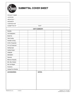


© Copyright 2026