
Straddles and Pack
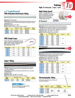
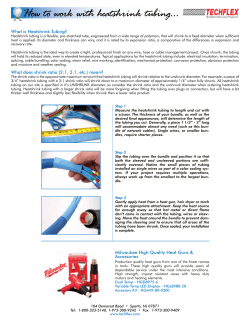
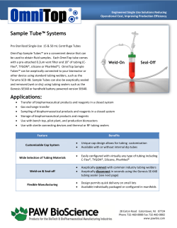
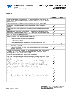
Straddles and Pack-Off Equipment
Straddles and Pack-Off Equipment
Introduction
Straddles and pack-offs play an important role in the
remediation of wellbore deficiencies. Halliburton's full line
of straddle and pack-off assemblies offer countless variations
for customizable solutions. Whether it is a retrievable casing
patch or a replacement for a worn-out gas lift mandrel,
Halliburton can supply the proper solution.
This chapter describes several types of straddle and packoff assemblies used in both casing and tubing applications.
The retrievable solutions featured in this chapter offer
varying installation options from workstring-installed to
wireline-installed.
HAL22087
Halliburton offers a large line of straddles and pack-offs to
help meet your well remediation needs. To determine which
Halliburton straddle is best suited for your situation, contact
your local Halliburton representative.
Straddle Assembly
Straddles and Pack-Off Equipment
7-1
BB0 Retrievable Straddle
The BB0 straddle is a large bore packoff device used to seal off damaged or
perforated tubing and isolate the
annulus from tubing pressure.
Run in a single trip, the straddle
incorporates dual packing elements
which provide the pressure seal. The
slip mechanisms anchor the straddle to
the wellbore and are contained within
the two packing elements, protected
from produced fines and well debris.
An intermediate pup joint assembly can
be lengthened to extend overall straddle
length if desired. The straddle is run
and retrieved using conventional well
intervention methods along with the
Halliburton RS and PK service tools.
Applications
The BB0 device is a ‘utility’ straddle
designed for a wide range of
applications. It has primarily been used
as a means of isolating damaged tubing
or short perforated intervals. The
straddle can also be used to isolate
redundant or leaking downhole tools,
such as side-pocket mandrels and
chemical injection subs.
Features
• One-trip run, two-trip retrieval
• One-piece dual modulus packing
element
• Compact, modular design
• Slip mechanisms isolated from
wellbore
• Slips mechanically retained on
retrieval
• Controlled setting action
• Large bore ID to OD ratio
• Field redressable
Benefits
• Packing element design enhances
the ability to return to original
shape upon release, thus reducing
the risk of hanging up
• Modular design allows for straddle
lengths to be varied from
approximately 10 to 60 ft between
packing elements
• Slip mechanisms isolated from
wellbore and protected from well
debris for improved reliability
• Controlled setting action and slip
design helps ensure stresses exerted
on the tubing are evenly distributed,
to help prevent damage
• Mechanically retained slips reduce
the risk of premature setting while
running in hole and hanging up on
retrieval
• Large bore ID reduces production
choke
• May be run and retrieved on
slickline, electric line, coiled tubing,
or workstring
HAL31626
• High running and retrieval speeds
• Large footprint segmented slips
BB0
Retrievable Straddle
7-2
Straddles and Pack-Off Equipment
BB0 Retrievable Straddles
Casing/Tubing
Pressure Rating
Maximum OD
Size
in.
2 7/8
3 1/2
4 1/2
5
6 5/8
7
Length
Weight
mm
Above
lb/ft
kg/m
in.
mm
6.4
9.52
2.280
57.91
8.7
12.95
2.140
54.36
73.03
88.90
114.30
168.28
177.80
mm
Below
psi
bar
psi
bar
5,000
344.50
5,000
344.50
5,000
344.50
5,000
344.50
25.40
Various
9.2
13.69
2.720
69.09
1.375
34.93
3,000
206.70
3,000
206.70
11.6
17.26
3.650
92.71
2.340
59.44
4,000
275.76
3,000
206.70
12.6
18.75
3.650
92.71
2.340
59.44
4,000
275.76
4,000
275.76
13.5
20.09
3.650
92.71
2.340
59.44
5,000
344.50
5,000
344.50
15.1
22.47
3.650
92.71
2.340
59.44
4,000
275.76
4,000
275.76
11.6
17.26
3.650
92.71
2.340
59.44
4,000
275.76
3,000
206.70
15
22.32
4.280
108.71
2.50
63.50
4,000
275.76
4,000
275.76
4.090
103.88
2.40
60.96
4,000
275.76
4,000
275.76
18
26.78
3.970
100.83
2.40
60.96
2,000
137.88
2,000
137.88
20.3
30.20
4.090
103.88
2.40
60.96
5,200
358.48
5,200
358.48
23.2
34.52
4.090
103.88
2.40
60.96
4,000
275.76
3,000
206.70
4.530
115.06
2.625
66.68
5,000
344.50
4,500
310.26
4.470
113.53
2.625
66.68
3,000
206.70
3,000
206.70
4.530
115.06
2.625
66.68
5,000
344.50
5,000
344.50
4.470
113.53
2.625
66.68
3,000
206.70
3,000
206.70
4.460
113.28
2.625
66.68
4,000
275.76
3,500
241.15
310.26
127.00
139.70
in.
1.000
17
5 1/2
Minimum ID
20
Various
Various
Various
25.29
29.76
23
34.22
4.460
113.28
2.625
66.68
5,000
344.50
4,500
26
38.69
4.280
108.71
2.340
59.44
5,000
344.50
5,000
344.50
32
47.62
5.500
139.70
3.400
86.36
5,000
344.50
5,000
344.50
26
38.69
5.935
150.75
3.625
92.08
3,000
206.70
3,000
206.70
29
43.16
5.720
145.28
3.625
92.08
5,000
344.50
4,000
275.76
32
47.62
5.720
145.28
3.625
92.08
5,000
344.50
5,000
344.50
35
52.08
5.720
145.28
3.625
92.08
5,000
344.50
5,000
344.50
38
56.55
5.635
143.13
3.625
92.08
4,000
275.76
4,000
275.76
Various
Various
Various
Part Number Prefix: P.815BB0
Straddles and Pack-Off Equipment
7-3
Evo-Trieve® Intervention Packer
Evolved from the industry-leading
B Series monobore intervention
product family, the Evo-Trieve packer
system features a robust cage-type slip
system that anchors the packer to the
wellbore while a packing element
provides a bi-directional pressure seal.
The Evo-Trieve intervention packer
may be run and retrieved with
conventional well intervention systems
in conjunction with field-proven
Halliburton service tools. The packer is
V0 qualified per ISO 14310 to 5,000 psi
and up to 275°F.
Applications
The Evo-Trieve intervention packer is a
modular utility packer designed to be
adaptable for a wide range of
monobore intervention applications.
• Primarily used as an anchoring
device for the suspension of well
intervention tools including water
injection valves, downhole gauge
and Storm Choke® safety valves
• May be used as an ISO-qualified
plugging device by attaching a
remote equalizing sub (pump-out
plug) or prong equalizing sub
• Serves as base conversion unit for
Evo-Trieve upper sealbore packer
and Evo-Trieve heavy hang-weight
packer typically used to deploy
velocity strings within gas wells
• Utilized as part of a system to
provide isolation straddle solutions
of any length
7-4
Features
• Supplied with H2S packing element
system as standard for critical well
deployment and reduced inventory
management
• Packing element positioned above
slips for improved debris protection
• Robust slip system permits no overexpansion in set position while
mechanically locked in retracted
position when released
• Improved body lock ring system
retains element pack-off force
during pressure reversals
• Incorporates field-proven sleevetype release mechanism
• Anti-reset ring helps provide
improved retrieval capabilities by
locking out external components
• Easily redressed in field or at rig site
Benefits
• Design allows operator to quickly
and economically adapt for use in
different operational requirements
• Compact design allows deployment
in restricted work areas where
limited rig-up height availability
makes for difficult access
• Controlled setting action and slip
design helps ensure stress exerted on
the casing or tubing is evenly
distributed thus preventing damage
• Mechanically retained slips reduce
premature setting risks while
running in hole and hanging up on
retrieval
• Packing element design enables it to
return to original shape upon
release, reducing hanging up risk
• Slip mechanism position offers
protection from casing debris for
improved reliability
• Packer may be run and retrieved on
slickline, electric line, coiled tubing,
or workstring
HAL32938
The Evo-Trieve® intervention packer is
a retrievable large bore pack-off device
for superior technical and operational
performance. This high-performance
packer can be set at a predetermined
point anywhere in the tubing or casing.
Evo-Trieve®
Intervention Packer
Part Number Prefix: P.803EB0; P.803ER0;
P.803EH0
Straddles and Pack-Off Equipment
BR0 Modular Straddle System
The BR0 modular straddle system allows the deployment
of long straddles in sections where running in one trip is
not possible due to available lubricator height restrictions.
The modular straddle system consists of the BR0 sealbore
packer and the RS2 tubing anchor seal assembly. The first
run places a lower BR0 packer with integral seal receptacle
immediately below the section to be isolated. An RS2
anchor latch, tubing, and upper RS2 seal receptacle (RS2
intermediate assembly) is then run and latched into the
lower BR0 packer’s seal receptacle. The required number of
RS2 intermediate assemblies are then run to make up the
desired straddle length. The final run consists of a RS2
anchor latch, pup joint, and upper BR0 packer.
Upper BR0 Packer
C/W Pup Joint and
RS2 Anchor Latch
A total of four RS2 intermediate assemblies can be installed
between BR0 packers. If longer straddle lengths are
required, intermediate BR0 packers are installed to allow
stack-up of additional RS2 intermediate assemblies.
Applications
The BR0 modular straddle system can be deployed in any
well where communication between the tubing and
annulus must be isolated. It is ideally suited to applications
where long straddles must be run but available lubricator
lengths will not allow one-trip installation.
The straddle sections may be run and retrieved using
conventional well intervention methods.
RS2 Intermediate
Assembly
The BR0 packers use Halliburton RO and PK service tools
while the RS2 intermediate assemblies use the industry
standard GS pulling tool.
HAL30917
Lower BR0 Packer
Run 1
Run 3
Run 2
BR0 Modular Straddle System
Straddles and Pack-Off Equipment
7-5
Features
• One-piece dual modulus packing
element
Benefits
• Helps maintain production and
avoid costly well workover
• Compact, modular design
• Slip mechanism position offers
protection from casing debris,
improving reliability
• Large footprint segmented slip
mechanism
• Packing element above the slips
offering improved debris protection
• Slip mechanism located below
packing element
• Controlled setting action
• Reduced risk of premature setting
while running in hole and hanging
up on retrieval
RS2 Anchor
Latch
• Allows high running and retrieval
speeds
• OD components rotationally locked
• Field redressable
• May be run and retrieved on
slickline, electric line, coiled tubing,
or workstring
RS2 Seal
Receptacle
RS2 Tubing Anchor
The RS2 tubing anchor assembly forms
an integral part of the BR0 modular
straddle system and allows long
straddles to be run in sections where
lubricator height is limited.
The RS2 incorporates an anchor latch
and mating seal receptacle which are
made up with a pre determined length
of tubing to form the RS2 intermediate
assembly. As multiple intermediate
assemblies are run in hole, the anchor
latch will land in the preceding
intermediate assembly’s seal receptacle,
or BR0 packer seal receptacle, to create
a tubing-to-annulus seal.
Benefits
• Anchor seal units are manufactured
from premium materials and are
designed to minimize stab-in seal
friction.
• One-piece seal mandrels reduce the
possibility of tubing leaks within the
straddle assembly.
• Anchor latch provides secure
engagement within the seal
receptacle with an overpull verifying
engagement.
Tubing
RS2 Anchor
Latch
• Pre-determined shear screw values
help ensure RS2 intermediate
assemblies are retrieved
sequentially.
Features
• Premium seals
• One-piece seal mandrel
• Secure engagement
BR0 Packer
Seal Receptacle
• Sequential retrieval
RS2 Intermediate
Assembly Stack-Up
7-6
Straddles and Pack-Off Equipment
BR0 Modular Straddle System
Casing/Tubing
Pressure Rating
Maximum OD
Size
Weight
in.
mm
2 7/8
73.03
3 1/2
4 1/2
5
5 1/2
6 5/8
7
Minimum ID
88.90
lb/ft
Above
kg/m
in.
mm
in.
mm
6.4
9.52
2.280
57.91
8.7
12.95
2.140
54.36
1.000
25.40
9.2
13.69
2.720
69.09
1.375
11.6
17.26
3.650
92.71
12.6
18.75
3.650
13.5
20.09
3.650
15.1
22.47
15.0
22.31
18.0
26.78
Below
psi
bar
psi
bar
5,000
344.50
5,000
344.50
5,000
344.50
5,000
344.50
34.93
3,000
206.70
3,000
206.70
2.340
59.44
4,000
275.76
3,000
206.70
92.71
2.340
59.44
4,000
275.76
4,000
275.76
92.71
2.340
59.44
5,000
344.50
5,000
344.50
3.650
92.71
2.340
59.44
4,000
275.76
4,000
275.76
4.280
108.71
2.500
63.50
4,000
275.76
4,000
275.76
4.090
103.89
2.400
60.96
4,000
275.76
4,000
275.76
3.970
100.84
2.400
60.96
2,000
137.88
2,000
137.88
114.30
127.00
139.70
168.28
177.80
20.3
30.20
4.090
103.89
2.400
60.96
5,200
358.48
5,200
358.48
23.2
34.52
4.090
103.89
2.400
60.96
4,000
275.76
3,000
206.70
4.530
115.06
2.625
66.68
5,000
344.50
4,500
310.26
17
25.29
4.470
113.54
2.625
66.68
3,000
206.70
3,000
206.70
4.530
115.06
2.625
66.68
5,000
344.50
5,000
344.50
4.470
113.54
2.625
66.68
3,000
206.70
3,000
206.70
4.460
113.28
2.625
66.68
4,000
275.76
3,500
241.15
4.460
113.28
2.625
66.68
5,000
344.50
4,500
310.26
38.68
4.280
108.71
2.340
59.44
5,000
344.50
5,000
344.50
32
47.62
5.500
139.70
3.400
86.36
5,000
344.50
5,000
344.50
26
38.69
5.935
150.75
3.625
92.08
3,000
206.70
3,000
206.70
29
43.16
5.720
145.29
3.625
92.08
5,000
344.50
4,000
275.76
32
47.6
5.720
145.29
3.625
92.08
5,000
344.50
5,000
344.50
35
52.1
5.720
145.29
3.625
92.08
5,000
344.50
5,000
344.50
38
56.55
5.635
143.13
3.625
92.08
4,000
275.76
4,000
275.76
20
29.75
23
34.21
26
Part Number Prefix: P.803BR0; P.250RS2
Straddles and Pack-Off Equipment
7-7
Retrievable Gas Lift Straddles
Designed to be positioned across prepunched tubing or set across existing
gas lift mandrels that have lost integrity
due to erosion or mechanical damage,
the injected gas passes through ports on
the straddle OD and into the
production flow via gas lift valves
incorporated within the straddle
system. Dual packing elements provide
the pressure seal while a slip
mechanism anchors the straddle to the
wellbore. The slip mechanism is
contained between the packing
elements, protected from produced
fines and well debris.
The BG0 Econolift gas lift straddle is
run in two trips with the straddle
installed on the first trip. An SU2 gas
injection head with integral gas lift
valve is then landed and locked into
the top of the straddle on the second
trip. Should failure of the gas lift valves
occur or changes in the wellbore
conditions require that the gas lift
valves be reconfigured, the SU2 gas
injection head may be retrieved and
the gas lift valves changed out without
the need to retrieve the entire straddle
assembly. Dummy (blank) plugs can
also be installed into the SU2 gas
injection head to isolate the flow path
if required.
The GL0 gas lift straddle and the BM0
Econolift gas lift straddle are both run
in a single trip with the gas lift valves
built into the straddle body. When
these gas lift valves need to be replaced,
the straddle is retrieved to surface and
the gas lift valves are replaced and then
repositioned downhole. The BM0 is
retrieved in one trip while the GL0 is
retrieved in sections over two trips.
7-8
Applications
BG0, BM0, and GL0 retrievable gas lift
straddles are specifically designed for
installation in wells where the cost of a
workover cannot be justified or where
the well must be closed in until a
workover can be planned. These
systems also allow gas injection to
depths previously unavailable or where
a failed chemical injection sub is
allowing hydrocarbons to enter the
injection control line.
Features
• Provide a gas lift solution to suit
from 2 7/8-in. to 7-in.
• GL0 and BM0 straddles run in a
single trip; retrieval for BM0 is
single trip, GL0 in two trips
• GL0 and BM0 straddles designed to
accommodate up to three industry
standard gas lift valves
• BG0 straddle and SU2 gas injection
head can be run and retrieved on
separate trips
• SU2 gas injection head
accommodates up to four industry
standard gas lift valves
• One-piece dual modulus packing
elements
• High running and retrieval speeds
• Large footprint segmented slips
• Slip mechanism isolated from
wellbore
• Slips mechanically retained on
retrieval
• Controlled setting action
• Field redressable
HAL31531
Halliburton’s retrievable gas lift
straddles allow the introduction of
controlled gas lift into a well without
the need for an expensive workover.
BG0 Retrievable
Gas Lift Straddle
Straddles and Pack-Off Equipment
Benefits
• BM0 straddle can be run and retrieved in a single trip,
minimizing rig time
• Although run and retrieved in two trips, the SU2 gas
injection head can be recovered, redressed, and replaced
without the need to retrieve the entire BG0 straddle
assembly
• Cost-effective solution for installation of controlled gas
lift in wells with depleted reservoirs
• Allows reinstatement of controlled gas lift in wells where
existing system has failed
• Allows extension of existing gas lift to depths previously
unavailable
• Helps prevent the need for an expensive workover
• Packing element design enhances ability to return to
original shape upon release, thus reducing the risk of
hanging up
• Slip mechanism isolated from the wellbore and protected
from well debris, thus improving reliability
• Mechanically retained slips reduce the risk of premature
setting while running in hole and hanging up on
retrieval
• Controlled setting action and slip design helps ensure
stresses exerted on tubing are evenly distributed, thus
preventing damage
Retrievable Gas Lift Straddles
Casing/Tubing
Size
Pressure Rating
Maximum OD
Minimum ID
kg/m
in.
mm
in.
Weight
Above
in.
mm
lb/ft
2 7/8
73.03
6.4
9.52
2.280
57.91
9.2
13.69
2.710
68.83
10.2
15.70
2.710
11.6
17.26
3.650
12.6
18.80
13.5
20.14
18.0
17
3 1/2
4 1/2
5
5 1/2
7
Below
mm
psi
bar
psi
bar
0.950
24.13
3,000
206.70
3,000
206.70
1.375
34.93
3,000
206.70
3,000
206.70
68.83
1.375
34.93
3,000
206.70
3,000
206.70
92.71
2.000
50.80
4,000
275.76
4,000
275.76
3.650
92.71
2.000
50.80
4,000
275.76
4,000
275.76
3.650
92.71
2.000
50.80
4,000
275.76
4,000
275.76
26.78
4.090
103.89
2.400
60.96
4,000
275.76
4,000
275.76
25.26
4.530
115.06
4,000
275.76
4,000
275.76
88.90
114.30
127.00
139.70
177.80
20.0
29.80
4.530
115.06
23
34.23
4.460
113.28
2.400
26.0
38.68
5.935
150.75
3.375
29
43.16
5.720
145.28
3.375
32.0
47.60
5.720
145.28
3.375
60.96
4,000
275.76
4,000
275.76
5,000
344.50
5,000
344.50
85.73
3,500
241.15
3,500
241.15
85.73
4,000
275.76
4,000
275.76
85.73
4,000
275.76
4,000
275.76
Part Number Prefix:P.815BG0; P.815BM0; P.815GL0
Straddles and Pack-Off Equipment
7-9
CV0 Retrievable Straddle with Integral Safety Valve
The CV0 straddle is an isolation device
designed to be installed across an
existing tubing-retrievable subsurface
safety valve (TRSSSV) or SSSV nipple
profile which has lost integrity.
Run and retrieved in a single trip, the
CV0 straddle incorporates dual packing
elements which seal the flow couplings
or pup joints on either side of the
TRSSSV or SSSV nipple. A slip
mechanism anchors the tool to the
wellbore and is contained between the
packing elements, protected from
produced fines and well debris.
Once in position, the straddle’s integral
safety valve is operated conventionally
by pressurizing the existing completion
hydraulic control line. A selection of
Halliburton insert valves is available to
suit a variety of applications.
Applications
• Specifically designed for
applications where an existing
TRSSSV has lost integrity or where
the SSSV nipple sealbore has been
damaged and can no longer provide
a pressure seal
• Provides a fully functional safety
valve that helps prevent the need for
an expensive workover
Features
• Uses existing completion
control line
• Adaptable to most completion
designs
• High running and retrieval speeds
• Large footprint segmented slips
• Slip mechanism isolated
from wellbore
• Slips mechanically retained
on retrieval
• Controlled setting action
• Field redressable
Benefits
• Cost-effective solution in situations
where the primary safety valve has
lost integrity
• Helps to prevent the need for an
expensive workover
• Packing element design enhances
ability to return to original shape
upon release, thus reducing the risk
of hanging up
• Slip mechanism isolated from the
wellbore and protected from well
debris, thus improving reliability
• Mechanically retained slips reduce
risk of premature setting while
running in hole and hanging up on
retrieval
• Controlled setting action and slip
design help ensure stresses exerted
on the tubing are evenly distributed,
thus preventing damage
• May be run and retrieved on
slickline, electric line, coiled tubing,
or workstring
HAL33216
• One-trip run and retrieve
• One-piece dual modulus
packing element
CV0 Retrievable Straddle
with Integral Safety Valve
7-10
Straddles and Pack-Off Equipment
CV0 Retrievable Straddle with Integral Safety Valve
Casing/Tubing
Pressure Rating
Maximum OD
Size
mm
3 1/2
88.90
5 1/2
7
Length
Weight
in.
4 1/2
Minimum ID
Above
Below
lb/ft
kg/m
in.
mm
in.
mm
psi
bar
psi
bar
ft
1.090
27.68
5,000
344.50
5,000
344.50
Various
1.845
46.86
5,000
344.50
5,000
344.50
Various
2.500
63.50
5,000
344.50
5,000
344.50
Various
3.22
81.79
5,000
344.50
5,000
344.50
Various
9.2
13.69
2.730
69.34
12.6
18.80
3.780
96.01
15.1
22.47
3.650
92.71
17
25.26
4.650
118.11
20.0
29.89
29
43.15
5.965
151.51
32.0
47.60
6.020
152.91
114.30
139.70
177.80
Part Number Prefix: P.815CV0
Straddles and Pack-Off Equipment
7-11
Otis® G Pack-Off Anchors
Otis® G pack-off anchors are designed to set anywhere in the
tubing string to straddle and pack off holes or other
communication in the tubing string, so well production can
be continued without pulling tubing. Anchors are run and
set by wireline methods under pressure without killing the
well. Pressure ratings for all Otis pack-off anchors are
dependent upon packing elements and condition of the
tubing string.
Slip-Type Holddown
The G pack-off anchor is particularly suited for installations
where a high volume of production is desired. The use of an
internal running and pulling neck permits a large internal
diameter. Large bore allows the use of properly sized wireline
tools (bottomhole pressure bombs, etc.). The anchor utilizes
an Otis D collar stop or G slip stop at the bottom. The collar
stop is designed to locate and lock in the collar recess of upset
or non-upset tubing. For streamlined tubing without collar
recess, a slip-type lower stop is available. The upper pack-off
section is usually anchored with a slip-type holddown. The G
pack-off assembly is designed to seal against the tubing wall
and is held in its set position by a mechanical lock. It is a
pressure-balanced unit designed to seal against pressures
from above and below.
Centralizers
Top Otis® G
Pack-Off Assembly
Spacer Pipe
Otis® D Collar Stop
Size
OD
ID
in.
mm
in.
mm
in.
mm
1.900
48.26
1.468
37.28
.750
19.05
2.063
52.40
1.593
40.46
.812
20.62
2.375
60.32
1.843
46.81
1.062
26.97
2.875
73.02
2.281
57.93
1.500
38.10
3.500
88.90
2.720
69.08
2.000
50.80
4.500
114.30
3.800
96.52
2.780
70.61
Bottom Otis G
Pack-Off Assembly
Otis® G Pack-Off Anchor
Weight
mm
1.900
48.26
lb/ft
kg/m
OD
ID
in.
mm
in.
mm
1.468
37.28
.742
18.84
2.063
52.40
1.593
40.46
.812
20.62
2.375
60.32
1.893
48.08
.957
24.30
2.875
73.02
2.281
57.93
1.500
38.1
3.500
88.90
9.2
13.68
2.840
72.13
1.880
47.75
43.18
10.3
15.32
2.700
68.58
1.700
12.95
19.26
2.550
13.77
1.520
38.60
4.500
114.30
12.6
18.74
3.805
96.64
2.792
70.90
5.500
139.70
17-20
25.2929.76
4.500
114.30
3.500
88.90
Otis D Collar
Stop
HAL12517
Size
in.
Centralizers
Otis® G Pack-Off Anchor
Ordering Information
Specify: tubing size and weight, thread nipple profiles and ID.
Part Number Prefix: G stop pack-off 13GO; D collar lock 13DO
7-12
Straddles and Pack-Off Equipment


© Copyright 2026