
AERONAUTICAL INFORMATION CIRCULAR
AIP Canada (ICAO) Aeronautical Information Circulars Effective 0901Z 08 January 2015 to 0901Z 05 February 2015 Published by NAV CANADA in accordance with ICAO Annexes 4 and 15 of the Convention on International Civil Aviation © 2015 NAV CANADA All rights reserved Source of Charts and Maps: © 2015 Her Majesty the Queen in Right of Canada Department of Natural Resources 08 JAN 15 AERONAUTICAL INFORMATION CIRCULAR SUMMARY 1/15 (Supersedes all previous summaries) The following Aeronautical Information Circulars are in effect: 4/95 Amendment to the Waste Disposal Clause in the Airport Zoning Regulations 9/98 Operation of Precision Approach Path Indicator (PAPI) Units 6/01 Potential Interference from broadcasting stations on VHF Radionavigation Receivers On Board IFR Aircraft Operating in France 27/06 Exemption from Subsection 602.34(2) of the Canadian Aviation Regulations 22/07 North American Free Trade Agreement (NAFTA) Advisory 15/08 IFR Approval of Global Navigation Satellite Systems (GNSS) in North Atlantic Minimum Navigation Performance Specifications (NAT MNPS) Airspace 16/08 Instrument Flight Rules (IFR) Operations Using Global Navigation Satellite System (GNSS) 14/09 Pilot Procedures for Exposure to Laser and Other Directed Bright Light Sources (Replaces AIC 24/08) 20/11 Emergency Security Control of Air Traffic (ESCAT) Plan (Replaces AIC 5/01) 21/11 Labrador Coast Aerodrome Traffic Frequency Corridor 26/11 VFR Navigation Charts—Clarification of the Maximum Elevation Figure 36/11 Implementation of Controller Pilot Data Link Communications in the Edmonton Flight Information Region/Control Area 37/11 Implementation of Controller Pilot Data Link Communications in the Montreal Flight Information Region/Control Area 39/12 Implementation of a 50 Nautical Mile Lateral Separation Minimum in the Edmonton Flight Information Region/Control Area (Supersedes AIC 11/11) 40/12 Notice of Mandate for Data Link Services in the North Atlantic Region (Supersedes AIC 24/12) 26/13 Inability of Air Traffic Controllers to Issue Clearances (Replaces AIC 11/13) 2/14 Notice of Planned Expansion of Mandate for Data Link Services in the North Atlantic Region 5/14 Instrument Landing System (ILS)—Replacement Program (Replaces AIC 42/12) 10/14 Trial of a Five-Minute Along-Track Longitudinal Separation Minimum in the Gander Oceanic Control Area (Supersedes AIC 17/12) 13/14 Airspace and Service Changes—Edmonton, Alberta 15/14 Implementation Planning of Controller Pilot Data Link Communications Services in Canadian Domestic Airspace (Replaces AIC 34/13) 23/14 Vancouver, British Columbia—Fraser River Corridor Common Air-To-Air Frequency 29/14 Glide Path Fluctuations Caused by Movement of Ground Traffic 30/14 Depiction of Five-Nautical-Mile Buffers Around Special Use Airspace Contained Within Canadian Flight Information Regions (Supersedes AIC 9/14) 31/14 Trial Implementation of Reduced Lateral Separation Minimum in the ICAO North Atlantic Region (Supersedes AIC 1/14) Note: Cette information est aussi disponible dans l’autre langue officielle. Page 1 of 2 08 JAN 15 32/14 Windsor-Toronto-Montreal Airspace and Services Review New RNAV Routes and Revoking of Airways 33/14 Automated Limited Weather Information System 1/15 Fit for Purpose The following Aeronautical Information Circulars have been cancelled: 35/13 Alberta Airspace and Services Project—New RNAV T-Routes and Class ‘E’ Airspace 20/14 Flight Planning Rules for Oceanic Traffic to Operate Through the Gander Oceanic Transition Area and Gander Domestic Control Terminal Area (Replaces AIC 14/14) 34/14 Peawanuck, Ontario—Establishment of Aviation Weather Service 35/14 Colville Lake, Northwest Territories—Establishment of Aviation Weather Services 36/14 Ogoki Post, Ontario—Establishment of Aviation Weather Service Page 2 of 2 AERONAUTICAL INFORMATION CIRCULAR SUMMARY 1/15 08 JAN 15 AERONAUTICAL INFORMATION CIRCULAR 1/15 FIT FOR PURPOSE 1.0 Section A: General Material This section contains guidelines that apply to all NAV CANADA publications 1.2 Rationale for This Initiative The goal of this document is to provide clarity as to the intended use of individual Aeronautical Information Publications (AIP). Use of publication in manners that do not align with their intended purpose can significantly and negatively impact safety. The following description of how and in what circumstances the various aeronautical publications should be used are presented to enhance safety and to encourage appropriate use. 1.3 NOTAM All publications are subject to amendment between publication/update cycles. These changes will be the subject of a NOTAM. It is imperative that the currency of all publications be verified by reference to current NOTAMs for the area and nature of operation. 1.4 The E-Pub Compact Disk (CD) This CD contains all 56-day cycle publications in electronic format. This includes the Canada Flight Supplement, Canada Air Pilot, LO and HI Enroute Charts and Canada Water Aerodrome Supplement. The information contained on this disk is for reference purposes only. IT IS NOT SUITABLE FOR AIR NAVIGATION PURPOSES. The electronic maps are NOT depicted to scale and are not necessarily of the same colours as the paper charts. Pilots and other users are advised to obtain and use paper charts and maps for air navigation purposes. 1.5 General Safety Statement It is fundamental that users understand and recognize the purpose and limitations of these aeronautical publications and use them only as intended. If operations beyond the stated purpose or outside the limitations are undertaken, alternative means of navigation and information need to be employed. 1.6 Feedback NAV CANADA appreciates your feedback on all our products and, wherever practicable, publications will reflect customer needs and requests. We kindly ask that you submit all question and/or comments to [email protected]. References: The material contained in this publication is consistent with: ICAO Annexes and Documents ▪ Annex 15 ▪ Annex 4 Transport Canada Documents ▪ Canadian Aviation Regulations CARS ▪ Aeronautical Information Manual AIM Note: Cette information est aussi disponible dans l’autre langue officielle. NAV CANADA Documents ▪ AIM Aeronautical Publications Page 1 of 9 08 JAN 15 2.0 Section B: Publication Specific Fit for Purpose Information This section contains material specific to each NAV CANADA publication. 2.2 B1. 1:500,000 VFR Navigation Chart (VNC) Series of Maps 2.2.1 Purpose The VNC series of 52 charts is intended for VFR navigation throughout Canada. It satisfies the requirements of visual air navigation for operations at/or below 12,500 feet ASL. It provides for: 1. Pre-flight planning: 2. 2.2.2 1.1 Drawing track lines and using magnetic variation information to determine track in °M; 1.2 Map reconnaissance to locate major features (cities, roads, railways, etc.) for lateral navigation; and 1.3 Establishing vertical flight profiles with reference to terrain and obstacle elevations. In-flight navigation: 2.1 Determining horizontal position relative to desired track with reference to ground features; 2.2 Determining distances, especially to destination; 2.3 Identifying aerodromes, waypoints, frequencies, airspace boundaries, etc.; and 2.4 Determining vertical position relative to obstacles and terrain. Limitations 3. This map series is subject to the following limitations: 3.1 Due to the scale of this chart (1:500,000), it should not be used for flight in low ceiling and visibility conditions. As a guide, the lowest weather minima established in TC AIM RAC Figure 2.7 is 1,000 feet AGL ceiling and 1 mile visibility in uncontrolled airspace; use of the 1:500,000 VNC series in such conditions is not advisable; 3.2 Not all obstacles will be shown – it is impracticable to guarantee all obstacles have been included; 3.3 Not all geographical or aeronautical features can be shown; 3.4 Due to the long chart update intervals (one, two or five years) some aeronautical information may not be current. Each VNC chart shows, under the title, the date of that edition, the date to which topographical data are corrected and the effective date of airspace amendments. New information (obstructions, restricted and advisory areas, revised control zones, etc.) is initially advertised by NOTAM or AIP Supplement, then published in the CFS and ultimately incorporated in a chart revision; and 3.5 The VNC contains less aeronautical information than the VFR Terminal Area Chart (VTA). Users are therefore asked to use VTA charts where available. It is essential that users understand the purpose and limitations of this product and use it only as intended. Page 2 of 9 AERONAUTICAL INFORMATION CIRCULAR 1/15 08 JAN 15 2.3 B2. 1:250,000 VFR Terminal Area Charts (VTA) Series of Maps 2.3.1 Purpose The VTA series of charts is intended for VFR navigation in the terminal area around seven high traffic areas. It provides for: 1. 2. 2.3.2 3. Pre-flight planning: 1.1 Drawing track lines and using magnetic variation information to determine track in °M; 1.2 Map reconnaissance to locate major features (cities, roads, railways, etc.) for lateral navigation; and 1.3 Establishing vertical flight profiles with reference to terrain, obstacles and runways. In-flight navigation: 2.1 Identifying arrival and departure routes and waypoints; 2.2 Determining horizontal position relative to desired track with reference to ground features; 2.3 Determining distances, especially to destination; 2.4 Determining vertical position relative to obstacles and terrain; and 2.5 Identifying control zones, frequencies and airspace boundaries. Limitations This map series is subject to the following limitations: 3.1 Due to the scale of his chart (1:250,000), it should not be used for flight in low ceiling and visibility conditions. As a guide, TC AIM RAC establishes weather minima for control zones as 1,000 feet AGL and 3 miles visibility; use of the 1:250,000 VTA series in such conditions is not advisable; 3.2 Not all obstructions will be shown – it is impracticable to guarantee all obstructions have been included. In general, only obstructions greater than 300 feet AGL or higher are shown as well as known obstructions lower than 300 feet AGL that are considered significant; 3.3 Not all geographical or aeronautical features can be shown; and 3.4 Some aeronautical information may not be current because the chart update interval is one year. Each VTA chart shows, under the title, the date of that edition, the date to which topographical data are corrected and the effective date of airspace amendments. New information (obstructions, restricted and advisory areas, revised control zones, etc.) is advertised by NOTAM or AIP Supplement, then published in the CFS and ultimately incorporated in a chart revision. It is essential that users understand the purpose and limitations of this product and use it only as intended. AERONAUTICAL INFORMATION CIRCULAR SUMMARY 1/15 Page 3 of 9 08 JAN 15 2.4 B3. Canada Flight Supplement (CFS) 2.4.1 Purpose This publication provides detailed IFR and VFR information for Canadian aerodromes as well as selected North Atlantic aerodromes. Associated services and national aviation infrastructure information is also included, organized into the following sections: General: Tables, legends and associated information necessary for interpretation of the material in the supplement. Aerodrome Directory: Data and sketches for Canadian aerodromes and heliports and selected aerodromes in the North Atlantic. Planning: Information for flight planning such as characteristics of airspace, flight restrictions, IFR routes and airway intersections. Radio Navigation and Communications: Data for radio navigation aids and communication facilities. Military: Flight procedures and data, including sections on procedures for flight in the USA, North Atlantic and Alaska, air/ground communications and military training routes/areas. Emergency: Emergency procedures. This publication is essential for safety and operational effectiveness in both IFR and VFR operations. It should be used for all pre-flight planning and in-flight operations and for emergency procedures. 2.4.2 Limitations The CFS, when used with relevant enroute and terminal publications, completes the total aeronautical information package required for a flight. The CFS is to be used as a reference for the planning and safe conduct of VFR or IFR air operations. The information contained in the CFS is current only to the effective date. Since CFS information may be amended or cancelled, NOTAMs and AIP Supplements must be consulted to ensure that the most current information is used for flight operations. The CFS does not contain information about water aerodromes; that information is contained in the Water Aerodrome Supplement (WAS). 2.5 B4. Water Aerodrome Supplement (WAS) 2.5.1 Purpose The Water Aerodrome Supplement (WAS) is published annually in March with English and French versions available. It contains detailed information for all water aerodromes shown on Canadian VFR charts under the following sections: a) Special Notices and General b) Aerodrome/Facility Directory c) Planning d) Radio Navigation and Communications e) Emergency Page 4 of 9 AERONAUTICAL INFORMATION CIRCULAR 1/15 08 JAN 15 2.5.2 Limitations The CWAS is to be used as a reference for the planning and safe conduct of VFR or IFR air operations to and from water aerodromes. The information contained in this supplement is current only to the effective date. Since WAS information may be amended or cancelled, NOTAMs and AIP Supplements must be consulted to ensure that the most current information is used for flight operations. Since the WAS is published annually, pilots should also consult a current CFS to ensure that they are aware of all aeronautical information that may impact their flight. Note that not all general information contained in the CFS is repeated in the WAS. 2.6 B5. Canada Air Pilot (CAP) 2.6.1 Purpose This series of seven volumes is updated every 56 days and provides aeronautical information primarily related to the IFR arrival or departure phases of flight and comprises the following flight procedure types: Instrument Approach Procedure (IAP) Diverse and Standard Instrument Departure (SID) Standard Instrument Arrival (STAR) Noise Abatement Procedure Visual Approaches It also contains ground operations information such as parking areas and de-icing facilities along with Aerodrome and Taxi Charts. 2.6.2 Limitations The CAP is not intended for use in VFR operations. The CAP is regularly amended by NOTAM and AIP Supplements, especially at high traffic aerodromes. Users must always check NOTAMs for their proposed areas of operation. The CAP procedure pages are necessarily complex. It is essential that pre-flight study be performed in every case to attain familiarity with each procedure anticipated at destination and alternate. The CAP GEN volume is an integral part of the CAP series. Users must be familiar with the general procedural and terminology material in this publication to safely use the seven core volumes. Please note that the CAP GEN is only published when there is a change to its content. 2.7 B6. Restricted Canada Air Pilot (RCAP) 2.7.1 Purpose This electronic publication provides aeronautical information related to the arrival or departure phases of flight and comprises the following procedure types: Instrument Approach Procedure (IAP) Diverse and Standard Instrument Departure (SID) Standard Instrument Arrival (STAR) Noise Abatement Procedure It also contains ground operations information in Aerodrome Charts. AERONAUTICAL INFORMATION CIRCULAR SUMMARY 1/15 Page 5 of 9 08 JAN 15 2.7.2 Limitations The RCAP is not intended for use in VFR operations. The RCAP does not have an Aerodrome Chart for every airport. The RCAP is available in CD format only. The RCAP differs from the CAP in that it provides procedures for specific operations and operators that can safely operate using alternative means of achieving safety. Only operators with specific (Ops Spec 099 or 410) authority from Transport Canada can legally fly these procedures because they have been designed with certain deviations from the regulations. These deviations are permitted because special crew training, operational procedures and/or aircraft capability permit. 2.8 B7. Enroute Low Altitude (LO) Chart 2.8.1 Purpose This chart series provides flight crews with information to facilitate navigation along ATS routes in compliance with air traffic services procedures. It is intended for use in the low level airspace structure (below 18,000 feet ASL). The LO chart series, comprising 10 charts, depicts aeronautical radio information, airways system, controlled/uncontrolled airspace structure, special use airspace, communication stations and selected aerodromes. It is used for IFR route planning and inflight navigation. 2.8.2 Limitations This IFR chart series is not suitable for VFR navigation as it provides no obstacle, terrain, road or other data needed for visual flight. Vertical coverage is up to, but not including, 18,000 feet ASL. The information contained on these charts is current only to the effective date. Since enroute information may be amended or cancelled, NOTAMs and AIP Supplements must be consulted to ensure that only current information is used for flight operations. 2.9 B8. Enroute High Altitude (HI) Chart 2.9.1 Purpose This chart series provides flight crews with information to facilitate navigation along high level airways and routes in compliance with air traffic control procedures. They are intended for use in high level airspace (18,000 feet ASL and above). This series comprises six HI charts depicting aeronautical radio information, high level airways structure, controlled/uncontrolled airspace structure, special use airspace, communication facilities and selected aerodromes. It is used for IFR route planning and inflight navigation. Page 6 of 9 AERONAUTICAL INFORMATION CIRCULAR 1/15 08 JAN 15 2.9.2 Limitations This IFR chart is not suitable for VFR navigation as it provides no obstacle, terrain, road or other data needed for visual flight. Vertical coverage includes 18,000 feet ASL (FL 180) and above. The information contained on this chart series is current only to effective date. Since enroute information may be amended or cancelled, NOTAMs and AIP Supplements must be consulted to ensure that only current information is used for flight operations. 2.10 B9. Terminal Area Chart (TAC) 2.10.1 Purpose This chart series provides flight crews with information to facilitate IFR navigation in the terminal area of aerodromes in compliance with air traffic services (ATS) procedures. It is intended to assist in the transition from the enroute portion of the flight to the arrival portion, or from the departure portion to the enroute portion, at those terminals where the airspace structure is relatively complex. The TAC depicts aeronautical radio information, airways system, controlled/uncontrolled airspace structure, special use airspace, communication stations and selected aerodromes in congested areas at a larger scale. This information is in addition to what is displayed on the enroute series and instrument procedure charts. 2.10.2 Limitations The eighteen-chart TAC series is for use up to, but not including, 18,000 feet ASL within Canadian Domestic Airspace and that airspace over international waters and foreign territory in which Canada accepts responsibility for the provision of air traffic control services. Charts for the Azores, Bermuda and Iceland (Keflavik) are included for military use. The set includes these terminal areas: SIDE 1 SIDE 2 Vancouver/Victoria Thunder Bay Edmonton Windsor Calgary Toronto Saskatoon Montreal Winnipeg Ottawa Iceland Quebec Azores Moncton Halifax Gander Bermuda Keflavik/Iceland The TAC is revised every 56 days. The information contained on this chart series is current only to the effective date. Since information may be amended or cancelled, NOTAMs and AIP Supplements must be consulted to ensure that only current information is used for flight operations. AERONAUTICAL INFORMATION CIRCULAR SUMMARY 1/15 Page 7 of 9 08 JAN 15 2.11 B 10. Aeronautical Information Publication (AIP) Canada (ICAO) 2.11.1 Purpose The AIP Canada (ICAO) provides an electronic version of general aeronautical data and information. It comprises of: Part 1 – General (GEN) Part 2 – Enroute (ENR) Part 3 – Aerodromes (AD) Part 4 – AIP Canada (ICAO) Supplements – updated every 28 days Part 5 – Aeronautical Information Circulars (AIC) – updated every 28 days The AIP Canada (ICAO) itself is updated every 56 days while the AIP Canada (ICAO) Supplements and Aeronautical Information Circulars (AICs) are updated every 28 days. 2.11.2 Limitations The AIP Canada (ICAO) provides only general infrastructure information. The remainder of the required information can be found in the publications. These include the CFS, CAP, RCAP, the HI and LO IFR chart series, as well as the TAC. Minor editorial changes may be made to the AIP Canada (ICAO) without notice. 2.12 B 11. Canadian Airport Charts (airport diagrams) 2.12.1 Purpose NAV CANADA publishes the Canadian Airport Charts on a-56 day cycle. The information in the Canadian Airport Charts provides pictorial displays of Canadian airport manoeuvring areas found in the Canada Air Pilot or the military GPH 200, and may be reproduced for the sole purpose of assisting pilots during aircraft ground movement operations. The Canadian Airport Charts is available online in PDF format and is free of charge. 2.12.2 Limitations Up-to-date information on flight planning procedures and airport services, including fuel, lighting and local prohibitions or procedures can be found in the CFS. 2.13 B 12. Aerodrome Obstacle Chart Type A 2.13.1 Purpose The Type A Obstacle Chart, in combination with relevant information published in the AIP Canada, provides the data necessary to enable an operator to comply with the operating limitations of ICAO Annex 6, Part I, Chapter 5 (paras 5.2.8 and 5.3), and Part III, Section II, Chapter 3 (Helicopters). These data allow aircraft operators to determine the ability of specific aircraft types under specific conditions, on departure from an airport, to clear obstacles with an engine inoperative. Aerodromes submit survey data to NAV CANADA who in turn makes it available to users as Type A Charts. Please visit https://www.navcanada.ca/EN/products-and-services/Pages/aero-nautical-information-chartsICAO-type-a-charts.aspx for information on the most current charts. Page 8 of 9 AERONAUTICAL INFORMATION CIRCULAR 1/15 08 JAN 15 2.13.2 Limitations The Type A Obstacle Chart series has been prepared for selected aerodromes for use by operators of large aircraft and provides detailed information with regard to significant obstructions in the approach/departure areas of runways. They are required for operational planning purposes. Only the charts listed on the NAV CANADA website are valid. The method by which this chart is used to extract the data and the format used to communicate the information to crews is the responsibility of the aircraft operator. James Ferrier Manager, Aeronautical Information Management AERONAUTICAL INFORMATION CIRCULAR SUMMARY 1/15 Page 9 of 9 16 OCT 14 AERONAUTICAL INFORMATION CIRCULAR 33/14 AUTOMATED LIMITED WEATHER INFORMATION SYSTEM NAV CANADA, the country’s provider of civil air navigation services, is upgrading the aviation weather service provision at part-time human weather observing sites. The upgrade is a Limited Weather Information System (LWIS) that generates additional weather reports outside the hours of human observations. These reports provide wind, temperature, dew point, and altimeter setting information. The LWIS information is updated on an hourly basis and can be obtained from the NAV CANADA Aviation Weather Web Site (AWWS), a flight information centre (FIC), or an area control centre (ACC). An example of the LWIS information on the AWWS is as follows: SACN65 CYRL 140700 LWIS CYRL 140700Z AUTO 27012KT 07/06 A3014= This upgrade will result in the availability of key weather elements 24 hours per day for all aviation weather observation sites across Canada and will significantly enhance weather forecasting and pilot flight planning. LWIS installations afford pilots the ability to conduct instrument approach procedures (IAPs) 24 hours per day at these aerodromes and at aerodromes where a Remote Altimeter Setting Source (RASS) is used for the IAPs. Monitor NOTAMs for the exact date and time of activation of LWIS at specific sites prior to publication in the Canada Flight Supplement (CFS). For further information please contact: NAV CANADA Customer Service 77 Metcalfe Street Ottawa, ON K1P 5L6 Tel.: Fax: E-mail: 800-876-4693 877-663-6656 [email protected] Chuck Montgomery Director AIM, Flight Operations, CNS Ops Note: Cette information est aussi disponible dans l’autre langue officielle. Page 1 of 1 16 OCT 14 AERONAUTICAL INFORMATION CIRCULAR 32/14 WINDSOR-TORONTO-MONTREAL AIRSPACE AND SERVICES REVIEW NEW RNAV ROUTES AND REVOKING OF AIRWAYS A goal of the Windsor-Toronto-Montreal (WTM) Airspace and Services Review Project is to revise the airspace and air route structure—utilizing area navigation (RNAV)—to achieve improved efficiency for air operations. This includes establishing low level fixed RNAV T-Routes and high level RNAV Q-Routes in place of Victor and Jet airways respectively. The latest phase of the WTM project focuses on the Toronto/Western Ontario/Montreal areas and involves establishing and revising RNAV T- and Q-Routes. These initiatives and decommissioning of VORs in the USA by the Federal Aviation Administration (FAA) will result in the revocation of some very high frequency/ultrahigh frequency (VHF/UHF) low level (Victor) and high level (Jet) airways. These changes will be published on the LO 6, 7 and 8 En Route Low Altitude, HI 4, 5 and 6 En Route High Altitude and Toronto terminal area charts effective 13 November 2014. For further information, please contact: NAV CANADA Customer Service Centre 77 Metcalfe Street Ottawa, ON K1P 5L6 Tel.: Fax: E-mail: 800-876-4693 877-663-6656 [email protected] Chuck Montgomery Director AIM, Flight Operations, CNS Ops Note: Cette information est aussi disponible dans l’autre langue officielle. Page 1 of 1 16 OCT 14 AERONAUTICAL INFORMATION CIRCULAR 31/14 TRIAL IMPLEMENTATION OF REDUCED LATERAL SEPARATION MINIMUM IN THE ICAO NORTH ATLANTIC REGION (Supersedes AIC 1/14) Introduction Advancements in aircraft avionics and air traffic management flight data processing systems have driven an initiative to analyze whether the lateral separation standard in the current North Atlantic (NAT) minimum navigation performance specification (MNPS) airspace can be reduced to increase the number of tracks available and therefore increase capacity at optimum flight levels. The purpose of this aeronautical information circular (AIC) is to notify a change to the implementation date for this reduced lateral separation minimum (RLatSM) initiative. Due to scheduling changes for flight data processing upgrades necessary to support RLatSM, the original date advertised in AIC 01/14 has been revised. On or soon after 12 November 2015, Gander, Shanwick, and Reykjavik area control centres (ACCs) will commence participation in the trial of a 25 nautical mile (NM) lateral separation minimum in portions of the Gander, Shanwick, and Reykjavik oceanic control areas (OCA). The information provided is intended for publication in the Spring 2016 Transport Canada Aeronautical Information Manual (TC AIM – TP 14371E). Background Track spacing for MNPS-approved aircraft is currently one degree of latitude, which equates nominally to 60 NM. The proposed change will reduce lateral separation for aircraft operating at the flight levels and tracks associated with the NAT Region Data Link Mandate airspace, which can be practically achieved by establishing tracks that are spaced by one-half-degree of latitude. This track spacing initiative will be referred to as RLatSM. RLatSM will be implemented using a phased approach, the first of which will introduce one-half-degree spacing between the two core tracks of the NAT-organized track system (OTS) from flight level (FL) 350 to FL 390 inclusive. At yet to be determined dates, Phase 2 will expand the implementation throughout the entire NAT OTS and Phase 3 will encompass the entire ICAO NAT region, including for converging and intersecting track situations. Note: Cette information est aussi disponible dans l’autre langue officielle. Page 1 of 3 16 OCT 14 Operator Eligibility and Participation Operators do not need to apply to be part of the trial and will be eligible to flight plan RLatSM tracks provided the flights are: a) MNPS approved; b) RNP4 approved; and c) Automated Dependent Surveillance–Contract (ADS-C) and controller-pilot data link communications (CPDLC) equipped and, where applicable, authorized. The required CNS systems must be operational and flight crews must report any failure or malfunction of global positioning system (GPS), ADS-C, or CPDLC equipment to air traffic control (ATC) as soon as it becomes apparent. Flight Planning Air traffic services (ATS) systems use Field 10 (Equipment) and Field 18 (Other Information) of the standard ICAO flight plan to identify an aircraft’s data link and navigation capabilities. The operator should insert the following items into the ICAO flight plan for FANS 1/A or equivalent aircraft: a) b) Field 10a (Radio communication, navigation and approach aid equipment and capabilities); − insert “J5” to indicate CPDLC FANS1/A SATCOM (Inmarsat) and/or “J7” to indicate CPDLC FANS1/A SATCOM (Iridium) data link equipment; and − insert “X” to indicate MNPS operational approval; Field 10b (Surveillance equipment and capabilities); − c) Field 18 (Other Information); − Page 2 of 3 insert “D1” to indicate ADS with FANS 1/A capabilities; insert the characters “PBN/” followed by “L1” for RNP4. AERONAUTICAL INFORMATION CIRCULAR 31/14 16 OCT 14 Current Version The current, and updated versions of the draft NAT RLatSM plan and associated documents are provided on the ICAO European and North Atlantic Office website: <www.paris.icao.int>, EUR & NAT Documents NAT Documents Planning documents supporting separation reductions and other initiatives Further Information For further Information, please contact: NAV CANADA Gander Area Control Centre P.O. Box 328 Gander, NL A1V 1W7 Attn: Jeffrey Edison, Manager, ACC Operations Direct line: 709-651-5223 E-mail: [email protected] Chuck Montgomery Director AIM, Flight Operations, CNS Ops AERONAUTICAL INFORMATION CIRCULAR SUMMARY 31/14 Page 3 of 3 16 OCT 14 AERONAUTICAL INFORMATION CIRCULAR 30/14 DEPICTION OF FIVE-NAUTICAL-MILE BUFFERS AROUND SPECIAL USE AIRSPACE CONTAINED WITHIN CANADIAN FLIGHT INFORMATION REGIONS (Supersedes AIC 9/14) Introduction To assist in efficiently planning routes that avoid restricted areas in Canadian flight information regions (FIRs), NAV CANADA is providing customers with depictions of currently published special use airspace that also show a surrounding five-nautical-mile buffer zone through which flight will not be permitted. The depictions are intended to provide a visual representation for operators to consider when preparing flight plans involving operations at and above flight level (FL) 290. This aeronautical information circular (AIC) supplements the information contained in AIC 9/14 with three additional restricted areas (CYR664, CYR665, and CYR666) and associated five-nautical-mile buffer zones from the Montreal FIR. The information provided is intended for publication in the Spring 2015 Transport Canada Aeronautical Information Manual (TC AIM – TP 14371E). Background As described in the TC AIM – TP 14371E, special use airspace may be classified as “Class F advisory” or as “Class F restricted” within Canadian Domestic Airspace (CDA). In accordance with International Civil Aviation Organization (ICAO) requirements, special use airspace may also be classified as a danger area when established over international waters, but controlled by Canadian air traffic control (ATC). Class F airspace is described in the Designated Airspace Handbook (DAH, TP 1820E) and depicted on HI or LO charts, as applicable. Canadian controllers apply a five-nautical-mile separation minimum to en route aircraft being provided with air traffic service (ATS) surveillance service from the boundary of special use airspace. NAV CANADA customers have indicated that it would be beneficial to have visual indication of this buffer zone. Flight Planning Considerations The depicted buffers around the boundaries of special use airspace that is at or above flight level (FL) 290 have been constructed using parallel lines measuring five nautical miles from the straight segments and using five-nautical-mile arcs from the curved portions. Operators are advised that the arc points represented as coordinates of latitude and longitude are not to be used as routing waypoints. Note: Cette information est aussi disponible dans l’autre langue officielle. Page 1 of 26 16 OCT 14 Vancouver FIR Page 2 of 26 AERONAUTICAL INFORMATION CIRCULAR 30/14 16 OCT 14 AERONAUTICAL INFORMATION CIRCULAR SUMMARY 30/14 Page 3 of 26 16 OCT 14 Page 4 of 26 AERONAUTICAL INFORMATION CIRCULAR 30/14 16 OCT 14 Edmonton FIR AERONAUTICAL INFORMATION CIRCULAR SUMMARY 30/14 Page 5 of 26 16 OCT 14 Page 6 of 26 AERONAUTICAL INFORMATION CIRCULAR 30/14 16 OCT 14 AERONAUTICAL INFORMATION CIRCULAR SUMMARY 30/14 Page 7 of 26 16 OCT 14 Page 8 of 26 AERONAUTICAL INFORMATION CIRCULAR 30/14 16 OCT 14 AERONAUTICAL INFORMATION CIRCULAR SUMMARY 30/14 Page 9 of 26 16 OCT 14 Montreal FIR Page 10 of 26 AERONAUTICAL INFORMATION CIRCULAR 30/14 16 OCT 14 AERONAUTICAL INFORMATION CIRCULAR SUMMARY 30/14 Page 11 of 26 16 OCT 14 Page 12 of 26 AERONAUTICAL INFORMATION CIRCULAR 30/14 16 OCT 14 AERONAUTICAL INFORMATION CIRCULAR SUMMARY 30/14 Page 13 of 26 16 OCT 14 Page 14 of 26 AERONAUTICAL INFORMATION CIRCULAR 30/14 16 OCT 14 AERONAUTICAL INFORMATION CIRCULAR SUMMARY 30/14 Page 15 of 26 16 OCT 14 Moncton FIR Page 16 of 26 AERONAUTICAL INFORMATION CIRCULAR 30/14 16 OCT 14 AERONAUTICAL INFORMATION CIRCULAR SUMMARY 30/14 Page 17 of 26 16 OCT 14 Page 18 of 26 AERONAUTICAL INFORMATION CIRCULAR 30/14 16 OCT 14 AERONAUTICAL INFORMATION CIRCULAR SUMMARY 30/14 Page 19 of 26 16 OCT 14 Page 20 of 26 AERONAUTICAL INFORMATION CIRCULAR 30/14 16 OCT 14 AERONAUTICAL INFORMATION CIRCULAR SUMMARY 30/14 Page 21 of 26 16 OCT 14 Page 22 of 26 AERONAUTICAL INFORMATION CIRCULAR 30/14 16 OCT 14 AERONAUTICAL INFORMATION CIRCULAR SUMMARY 30/14 Page 23 of 26 16 OCT 14 Page 24 of 26 AERONAUTICAL INFORMATION CIRCULAR 30/14 16 OCT 14 AERONAUTICAL INFORMATION CIRCULAR SUMMARY 30/14 Page 25 of 26 16 OCT 14 Gander FIR Further Information For further Information, please contact: NAV CANADA Attn: Jeff Dawson Director, Operational Support Direct line: 613-563-7341 E-mail: [email protected] Chuck Montgomery Director AIM, Flight Operations, CNS Ops Page 26 of 26 AERONAUTICAL INFORMATION CIRCULAR 30/14 16 OCT 14 AERONAUTICAL INFORMATION CIRCULAR 29/14 GLIDE PATH FLUCTUATIONS CAUSED BY MOVEMENT OF GROUND TRAFFIC This aeronautical information circular (AIC) will advise operators of the conditions under which glide path signals will be protected, and will detail pilot responsibilities to notify air traffic controllers (ATC) when conducting, auto-land or similar approaches. Background In recent years, there has been an increase in reports from both pilots and air traffic controllers of instances of glide path fluctuations while an aircraft is navigating on the Instrument Landing System (ILS). This may occur when aircraft or vehicles are moving through the glide path critical area causing interference with the signal. In several cases, the aircraft automation/autopilot followed momentary ILS fluctuations causing the aircraft to pitch and roll. It has become evident that further clarity is required regarding when ILS signals are protected while an aircraft is established on an ILS approach. ILS signals will only be protected under the conditions described below. Glide Path Signal Protection Procedures A controller will protect the glide path signal when: 1. The ceiling is less than 1,000 feet or visibility is less than 3 miles, or both; and 2. The arriving aircraft is inside the final approach fix (FAF) on an ILS approach. Note: At uncontrolled airports, aircraft maneuvering on the ground may enter ILS critical areas during taxi, takeoff or landing. The ILS critical areas are not protected when aircraft are outside the FAF. Furthermore, with the exception of CAT II/III operations, localizer signal protection is not applied when a preceding aircraft will pass over or through the critical area while taking off, landing, or executing a missed approach on the same or another runway. Pilots must be aware of the ILS signal interference threats as well as flight display indications and autopilot functionality during manual or fully coupled ILS approaches. Auto-Land or Practice Low Visibility Approaches In situations where protection of the ILS signal is not required and pilots wish to conduct auto-land or practice low visibility approach procedures, advise the controller of your intentions early enough so that they can either protect the ILS critical area or advise you that due to traffic ILS critical area protection is not possible. If ILS critical area protection is not possible, the controller will use the phrase “ILS CRITICAL AREA NOT PROTECTED.” It then becomes the pilot’s responsibility to continue or discontinue in the particular approach procedure. Advisory Notice An ILS performance report is available for all Canadian runways on the NAV CANADA website. Note: Sections 3.12.1 to 3.12.3 of the Transport Canada AIM should be reviewed to ensure an understanding of ILS operating characteristics. Appendix A, items 1, 2, and 3 of TP 1490, MANUAL of ALL WEATHER OPERATIONS should also be reviewed for an understanding of ILS CRITICAL SENSITIVE AREAS. Note: Cette information est aussi disponible dans l’autre langue officielle. Page 1 of 2 16 OCT 14 Publication The Transport Canada Aeronautical Information Manual (TC AIM – TP14371E) will be amended in the April 2015 release. Validity Effective 31 October 2014. For further information, please contact: NAV CANADA Attn: Claude Fortier, Manager ATS, Standards & Procedures Tel.: E-mail: 613-563-5738 [email protected] Chuck Montgomery Director AIM, Flight Operations, CNS Ops Page 2 of 2 AERONAUTICAL INFORMATION CIRCULAR 29/14 26 JUN 14 AERONAUTICAL INFORMATION CIRCULAR 23/14 VANCOUVER, BRITISH COLUMBIA FRASER RIVER CORRIDOR COMMON AIR-TO-AIR FREQUENCY Introduction This circular is intended to provide communication guidelines for pilots operating along the Fraser River Valley corridor between Chilliwack and Pitt Meadows airports. In order to enhance traffic awareness and aviation safety in this congested airspace outside the control of air traffic control (ATC), common air-to-air frequencies have been designated for use along this corridor. Flight Training Frequencies and Fraser River Corridor Common air-to-air frequencies have been designated for use in the CYA flight-training areas that border the Fraser River (see backside of Vancouver visual flight rules [VFR] terminal area chart [VTA]). To ensure pilots who fly along the Fraser River corridor and between the flight training CYAs can communicate to maintain situational awareness and avoid conflicts, the common air-to-air flight training frequencies have been designated for use along the corridor as follows (see map sketch below): Glen Valley, Pitt (CYA 188 & 185) Fraser River west of Mission Bridge VFR Checkpoint 122.72(5) MHz Sumas, Harrison (CYA 187 & 186) Fraser River east of Mission Bridge VFR Checkpoint 122.77(5) MHz Note: Cette information est aussi disponible dans l’autre langue officielle. Page 1 of 3 26 JUN 14 NOT FOR NAVIGATION Communication Guidelines Pilots are encouraged to use the designated common air-to-air flight training frequency when flying within the flight training CYAs and along the designated portion of the Fraser River corridor. Radio transmissions on the frequencies should be the minimum required to provide the aircraft’s position and pilot intentions. Flying within areas designated for use of a common air-to-air frequency does not alleviate a pilot from the responsibility for monitoring and/or communicating on, when required, an ATC frequency, aerodrome traffic frequency (ATF) or mandatory frequency (MF) or any other appropriate frequency. Page 2 of 3 AERONAUTICAL INFORMATION CIRCULAR 23/14 26 JUN 14 Implementation There is no formal implementation or start date for using the designated common air-to-air flight training frequencies along the Fraser River corridor. Pilots should employ this best practice at their earliest opportunity. Information concerning the common air-to-air flight-training frequencies along the Fraser River corridor will be published on the planning map on the backside of the next edition of the Vancouver VTA (39th Edition) to be available early July 2014. A textual and graphic representation of the Fraser River corridor and flight training CYAs will be published in the Planning Section (British Columbia) of the Canada Flight Supplement (CFS) – 18 September 2014. Further Information For further information please contact: NAV CANADA Customer Service 77 Metcalfe Street Ottawa, ON K1P 5L6 Tel.: Fax: E-mail: 800-876-4693 877-663-6656 [email protected] Chuck Montgomery Director, AIS and Flight Inspection AERONAUTICAL INFORMATION CIRCULAR SUMMARY 23/14 Page 3 of 3 3 APR 14 AERONAUTICAL INFORMATION CIRCULAR 15/14 IMPLEMENTATION PLANNING OF CONTROLLER PILOT DATA LINK COMMUNICATIONS SERVICES IN CANADIAN DOMESTIC AIRSPACE (Replaces AIC 34/13) Introduction On 16 December 2011, NAV CANADA commenced the use of controller pilot data link communications (CPDLC) within the Canadian Domestic Airspace (CDA), with services offered in the Montreal, Edmonton, Vancouver, Winnipeg, Moncton, and Gander (Domestic airspace) flight information region (FIR). It is the intent of NAV CANADA to expand CPDLC service into the Toronto FIR in early part of 2014. As with the services offered in the other FIRs implementation of CPDLC in the Toronto FIR will be via a phased approach, as detailed below. Purpose of Circular This circular advises operators of the service area coordinates and expected implementation timelines for the Toronto FIR. Specific start dates for each of the implementation phases will be announced via Notice to Airmen (NOTAM). A description of the implementation phases, flight crew procedures, and supported CPDLC messages are also detailed below. Note: Cette information est aussi disponible dans l’autre langue officielle. Page 1 of 9 3 APR 14 Page 2 of 9 AERONAUTICAL INFORMATION CIRCULAR 15/14 3 APR 14 Moncton Area Control Center The Moncton CPDLC service area is flight level (FL) 290 and above, in the portion of the Moncton FIR/CTA bounded by: 41° 52’ 00” N 67° 00’ 00” W to 44° 30’ 00” N 67° 00’ 00” W 44° 30’ 00” N 67° 00’ 00” W to 44° 56’ 00” N 67° 00’ 00” W 44° 56’ 00” N 67° 00’ 00” W to 45° 37’ 30” N 67° 46’ 30” W 45° 37’ 30” N 67° 46 30 W to 45° 47’ 00” N 67° 48’ 17” W 45° 47’ 00” N 67° 48’ 17” W to 45° 49’ 30” N 67° 35’ 00” W 45° 49’ 30” N 67° 35’ 00” W to 46° 08’ 35” N 67° 13’ 00” W 46° 08’ 35” N 67° 13’ 00” W to 46° 12’ 00” N 67° 13’ 00” W 46° 12’ 00” N 67° 13’ 00” W to 46° 32’ 08” N 67° 17’ 59” W ARC Start 46° 32’ 08” N 67° 17’ 59” W to 35 Mile ARC Centred on 46° 57’ 00” N 67° 53’ 12” W ARC End 47° 17’ 20” N 68° 34’ 24” W to 47° 23’ 35” N 69° 00’ 00” W 47° 23’ 35” N 69° 00’ 00” W to 48° 00’ 00” N 69° 00’ 00” W 48° 00’ 00” N 69° 00’ 00” W to 48° 09’ 40” N 69° 19’ 45” W 48° 09’ 40” N 69° 19’ 45” W to 48° 53’ 20” N 69° 30’ 00” W 48° 53’ 20” N 69° 30’ 00” W to 49° 11’ 15” N 68° 40’ 00” W 49° 11’ 15” N 68° 40’ 00” W to 51° 00’ 00” N 68° 40’ 00” W 51° 00’ 00” N 68° 40’ 00” W to 51° 30’ 00” N 67° 00’ 00” W 51° 30’ 00” N 67° 00’ 00” W to 51° 53’ 00” N 65° 43’ 04” W 51° 53’ 00” N 65° 43’ 04” W to 51° 58’ 32” N 65° 22’ 15” W 51° 58’ 32” N 65° 22’ 15” W to 52° 07’ 27” N 64° 47’ 59” W 52° 07’ 27” N 64° 47’ 59” W to 52° 32’ 21” N 63° 07’ 24” W 52° 32’ 21” N 63° 07’ 24” W to 52° 49’ 10” N 61° 54’ 48” W 52° 49’ 10” N 61° 54’ 48” W to 51° 30’ 00” N 59° 45’ 00” W 51° 30’ 00” N 59° 45’ 00” W to 48° 50’ 00” N 57° 45’ 00” W 48° 50’ 00” N 57° 45’ 00” W to 44° 26’ 48” N 56° 03’ 06” W 44° 26’ 48” N 56° 03’ 06” W to 43° 35’ 00” N 55° 45’ 00” W 43° 35’ 00” N 55° 45’ 00” W to 42° 30’ 00” N 60° 00’ 00” W 42° 30’ 00” N 60° 00’ 00” W to 42° 20’ 12” N 61° 36’ 36” W 42° 20’ 12” N 61° 36’ 36” W to 41° 37’ 00” N 67° 00’ 00” W 41° 37’ 00” N 67° 00’ 00” W to 41° 52’ 00” N 67° 00’ 00” W AERONAUTICAL INFORMATION CIRCULAR 15/14 Page 3 of 9 3 APR 14 Gander Area Control Center The Gander domestic CPDLC service area is FL 290 and above, in the portion of the Gander FIR/CTA bounded by: 43° 35’ N 055° 45’ W to 48° 50’ N 057° 45’ W 51° 30’ N 059° 45’ W to 52° 49’ 10” N 061° 54’ 48” W to 51° 53’ 01” N 065° 43’ W 51° 30’ N 067° 00’ W to 51° 00’ N 068° 40’ W 53° 32’ N 068° 40’ W to 57° 33’ N 064° 00’ W 58° 50’ 40” N 063° 00’ W to 65° 19’ N 063° 00’ W 65° 23’ N 062° 38’ W to 65° 30’ N 060° 00’ W 65° 42’ 36” N 058° 23’ 56” W to 65° 00’ N 057° 45’ W 63° 30’ N 055° 45’ W to 63° 30’ N 055° 00’ W 53° 52’ N 054° 58’ W to 53° 05’ N 054° 05’ W 51° 00’ N 050° 00’ W to 44° 30’ N 050° 00’ W to the point of beginning. Winnipeg Area Control Center The Winnipeg CPDLC service area is FL 290 and above, in the portion of the Winnipeg FIR/CTA bounded by: 49° 00’ N 110° 00’ W to 49° 50’ N 109° 00’ W 51° 11’ N 109° W to 51° 20’ N 109° 30’ W 51° 30’ N 110° W to 53° 25’ 15” N 110° 00’ W then via a 60 nautical mile (NM) arc counter-clockwise around the Cold Lake TACAN (UOD) 54° 46’ N 108° 41’ 40” W 54° 46’ N 108° 25’ W to 55° 20’ N 107° 25’ W 53° 00’ N 102° 00’ W to 52° 26’ N 101° 00’ W 52° 46’ N 99° 08’ W to 52° 20’ N 95° 00’ W 52° 08’ N 95° 53’ W to 51° 20’ N 89° 23’ W 49° 54’ N 84° 12’ W to 47° 05’ N 87° 00’ W Then via a 35 NM arc clockwise around CYQT to 47° 54’ 30” N 88° 46’ 30” W 48° 06’ 30” N 90° 06’ W to 48° 34’ 15” N 91° 50’ W 48° 58’ 30” N 93° 24’ W to 49° 00’ N 97° 43’ W then along 49° N latitude to the point of beginning. Page 4 of 9 AERONAUTICAL INFORMATION CIRCULAR 15/14 3 APR 14 Vancouver Area Control Center The Vancouver CPDLC service area is FL 290 and above in the portion of the Vancouver FIR/CTA bounded by: 49° 00’ 02” N 115° 29’ 59” W Then west along the Canada/US boundary to 48° 29’ 36” N 124° 43’ 38” W to 48° 30’ N 125° W to 48° 20’ N 128° W to 51° N 133° 45’ W to 54° N 136° W to 54° 13’ N 134° 57’ W to Then along the Canada/Anchorage (US) boundary to 54° 39’ 44” N 132° 41’ 03” W 57° N 132° 03’ 58” W to 56° N 123° 15’ W 53° 24’ N 119° W to 50° 19’ 35” N 116° 05’ 05” W then west along the arc of a circle 25 NM radius centred on Skookum, BC non-directional beacon (NDB) to to 49° 57’ 18” N 115° 47’ 32” W to to 49° 57’ 45” N 115° 08’ 50” W to 49° 30’ N 115° 08’ 15” W 49° 00’ 02” N 115° 29’ 59” W to the point of beginning. Toronto Area Control Center On or after April 2014, the Toronto ACC will begin application of CPDLC in the Toronto FIR/CTA. The Toronto CPDLC service area is FL 290 and above in the portion of the Toronto FIR/CTA bounded by: 44° 13’ 17” N 76° 11’ 30” W Then west along Canada/US boundary to 47° 46’ 29” N 87° W to 49° 32’ N 87° W to 50° N 86° 16’ W to 52° N 83° 08’ 30” W to 53° 28’ N 80° W to 49° N 79° W to Then counter clockwise along the arc of a circle of 25 NM radius centred on Rouyn, QC NDB to 48° 35’ 13” N 79° W 47° 50’ 24” N 78° 33’ 56” W to 47° 33’ 15” N 78° 07’ 03” W to 47° 06’ 39” N 77° 32’ 45” W to 46° 56’ 48” N 77° 15’ W to 46° 08” N 77° 15’ W to 45° 57’ 40” N 76° 55’ 40” W to 45° 50’ 15” N 76° 16’ W to 44° 13’ 17” N 76° 11’ 30” W to the point of beginning. AERONAUTICAL INFORMATION CIRCULAR 15/14 Page 5 of 9 3 APR 14 Phased Implementation Phase 1 – Basic Request Phase This initial phase will enable an aircraft to make various speed and altitude requests using CPDLC. The response from the ACC ground system will be a free text acknowledgement that the request has been received and that a response from air traffic control (ATC) will be provided by the appropriate ACC via voice. Phase 2 – Advising Domestic Frequencies This phase introduces the assignment of domestic contact frequencies via CPDLC. Analysis of voice traffic indicates that such messages represent a significant proportion of existing voice traffic, and using CPDLC to carry out this function would be a useful contribution to reducing voice congestion. Phase 3 – Support En Route Altitude Changes and Speed Changes This phase will enable aircraft to request En Route altitude changes, En Route speed changes, and to report Leaving/Reaching Levels via CPDLC. Responses to these requests from the ACC will also be via CPDLC. Phase 4 – Full Implementation With the exception of those messages deemed unsafe by International Civil Aviation Organization (ICAO), specified downlink elements will be supported. Domestic ACCs will develop appropriate procedures to respond to all received downlink message elements. ATC will not provide information regarding when or where a flight can expect to climb or descend, due to the potential misunderstanding that such a message constitutes a clearance. Page 6 of 9 AERONAUTICAL INFORMATION CIRCULAR 15/14 3 APR 14 Supported Downlink Messages Supported downlink messages will be published via NOTAM. Any downlink message other than indicated in the NOTAM will generate a “MESSAGE NOT SUPPORTED BY THIS FACILITY” response from the ground system. Flight Planning Air traffic services (ATS) systems use field 10 (Equipment) of the standard ICAO flight plan to identify an aircraft’s data link capabilities. For ICAO 2012 format flight plans, operators should insert the following items into the ICAO flight plan form for FANS 1/A-equipped aircraft: 1. Field 10a (Radio communication, navigation, and approach equipment): insert the indicator(s) “J1 – J7” to indicate appropriate data link equipment as per the table below. Field 10a Indicator Type of Data Link Equipment J1 CPDLC FANS 1/A ATN VDL Mode2 J2 CPDLC FANS 1/A HFDL J3 CPDLC FANS 1/A VDL Mode 4 J4 CPDLC FANS 1/A VDL Mode 2 J5 CPDLC FANS 1/A SATCOM (INMARSAT) J6 CPDLC FANS 1/A SATCOM (MTSTAT) J7 CPDLC FANS 1/A SATCOM (IRIDIUM) AERONAUTICAL INFORMATION CIRCULAR 15/14 Page 7 of 9 3 APR 14 ATS Facilities Notification (AFN) Logon A CPDLC connection is initiated by the ground system in response to an AFN logon received from the aircraft. It is important, when initializing the flight management computer (FMC), to ensure that aircraft identification matches the identification displayed in the filed ATC flight plan message. If a flight becomes aware that incorrect flight identification data was provided in the AFN logon, the data link must immediately be terminated and a new AFN logon performed with the correct information. Flights entering any CDA CPDLC service areas from airspace where FANS 1/A ATS data link services are being received do not need to perform another AFN logon. Flights entering the CDA CPDLC service areas from airspace where no FANS 1/A ATS data link services are being received should perform an AFN logon: a) 15 to 45 minutes prior to entering the airspace; or b) prior to departure if departing airports are adjacent to, or underlying, the airspace. The AFN logon address for flights entering CDA facilities are as follows: Facility Name Facility Identifier for AFN Logon Montreal Area Control Centre CZUL Edmonton Area Control Centre CZEG Moncton Area Control Centre CZQM Gander Area Control Centre (Domestic) Gander Area Control Centre (Oceanic) CDQX (Domestic identifier) CZQX Winnipeg Area Control Centre CZWG Vancouver Area Control Centre CZVR Toronto Area Control Centre CZYZ Flights exiting the CDA CPDLC service areas into adjacent airspace where data link services are offered should not need to perform another AFN logon. Under normal circumstances, the current and next ATS units automatically transfer CPDLC and Automated Dependent Surveillance–Contract (ADS-C) services. The transfer is seamless to the flight crew. Communication of CPDLC Service Capability CPDLC will supplement existing very high frequency (VHF) voice as modes of direct controller pilot communications (DCPC) or high frequency (HF) as a third party mode of communications, within CDA. Aircraft that are entering a Canadian Domestic CPDLC service area and have performed an AFN logon are not required to use the term “C-P-D-L-C” on initial check-in or in other radio-telephony communications with ATC. Contact with Aero Radio – Flight Crew Where VHF communications is not available in CDA; pilots shall contact the appropriate Aero Radio station and on initial contact shall do the following: 1. Do not include a position report; 2. Use the term “C-P-D-L-C” after the aircraft call sign; 3. If required request the SELCAL check. The following is a sample exchange with Gander Aero Radio: GANDER RADIO, AIRLINE FIVE FIVE ONE C–P–D–L–C, FLIGHT LEVEL 350; REQUEST SELCAL CHECK FDAB Page 8 of 9 AERONAUTICAL INFORMATION CIRCULAR 15/14 3 APR 14 Contact For further information on CPDLC service in the Canadian Domestic FIR/CTA and the expansion of this service, please contact Pedro Vicente, Manager ATM Systems and ACC Automation NAV CANADA Tel.: E-mail: 613-248-6965 [email protected] Chuck Montgomery Director, AIS and Flight Inspection AERONAUTICAL INFORMATION CIRCULAR 15/14 Page 9 of 9 3 APR 14 AERONAUTICAL INFORMATION CIRCULAR 13/14 AIRSPACE AND SERVICE CHANGES EDMONTON, ALBERTA NAV CANADA has completed an aeronautical study that reviewed the structure of the airspace surrounding the Edmonton International and Villeneuve airports. The study was prompted by the closure of the Edmonton City Centre Airport and changes to traffic patterns resulting from the Alberta Airspace and Services Project. The study recommends the following airspace and service changes (see map sketch below): • Reduce the size of the 40 nautical mile (NM) oval-shaped terminal control area (TCA) to a 35 NM circular shape centred on the Edmonton Intl Airport. The TCA floor between the 30 and 35 NM rings remains at 9,500 feet above sea level (ASL); • Establish a new 25 NM ring based at 4,600 feet ASL. Between the 25 NM and 30 NM rings establish Class E transponder (Mode C) required airspace from 4,600 feet ASL to below 7,000 feet ASL; • Increase the radius of the Villeneuve control zone (CZ) from 3 to 5 NM; • Classify the airspace east of the Villeneuve CZ as Class E, transponder (Mode C) required from 3,000 feet ASL to below 3,400 feet with the TCA Class C airspace from 3,400 feet ASL and above; • Classify the airspace southeast (SE) of the Villeneuve CZ that stretches to the Edmonton Intl CZ and that also encompasses the former Edmonton City Centre CZ and the Namao Military Flight Advisory Unit Airspace as Class E transponder (Mode C) required from 3,000 feet ASL to below 3,400 feet ASL south of Whitemud Drive and from 3,000 feet ASL to below 4,100 feet ASL north of Whitemud Drive; • Increase the height of the Namao CZ from 3,400 feet ASL to below 4,100 feet ASL and adjust the Namao Military Flight Advisory Unit airspace boundaries; • Increase the height of CYA202(S) to 9,500 feet ASL and increase the radius from 2 to 5 NM; • Publish an air traffic frequency for pilot-to-pilot communication outside the TCA and CZs to be used in a defined area over the city of Edmonton and change the aerodrome traffic frequency (ATF) for the five hospitals and Eastport heliports to this common air traffic frequency. Note that in the interim until this new frequency is acquired the previous Edmonton City Centre tower frequency 119.1 MHz is to be used for the heliport ATFs; • Publish a right-hand circuit for Runway 26 at the new Parkland airport located 13 NM northwest of the Edmonton Intl airport; • Decommission the Blatchford (ZXD) non-directional beacon (NDB); • Decommission the Edmonton City Centre Legacy Automated Weather Observation System (AWOS) and discontinue the aerodrome forecast (TAF). Relocate the three aviation weather cameras from the Legacy AWOS to another location in the city of Edmonton; and • Publish the Edmonton and Calgary visual flight rules (VFR) terminal area charts (VTA) separately. The reverse side of the VTAs would be available to display special procedures and areas of particular interest or complexity. Note: Cette information est aussi disponible dans l’autre langue officielle. Page 1 of 3 3 APR 14 Publication Changes The following publications will be amended 29 May 2014 at 0901 Coordinated Universal Time (UTC): • Canada Flight Supplement (CFS) – Edmonton VFR Terminal Procedures Chart; and • Edmonton VNC (AIR 5005), 26th Edition and Edmonton VTA (AIR 1906), 20th Edition available 29 May 2014. For further information, please contact: Customer Service NAV CANADA 77 Metcalfe Street Ottawa, ON K1P 5L6 Tel.: Fax: E-mail: 800-876-4693 877-663-6656 [email protected] Chuck Montgomery Director, AIS and Flight Inspection Page 2 of 3 AERONAUTICAL INFORMATION CIRCULAR 13/14 3 APR 14 New Edmonton Airspace AERONAUTICAL INFORMATION CIRCULAR 13/14 Page 3 of 3 6 MAR 14 AERONAUTICAL INFORMATION CIRCULAR 10/14 TRIAL OF A FIVE-MINUTE ALONG-TRACK LONGITUDINAL SEPARATION MINIMUM IN THE GANDER OCEANIC CONTROL AREA (Supersedes AIC 17/12) Introduction Since 28 March 2011, as part of a program to improve service provision in North Atlantic (NAT) airspace, Gander area control centre (ACC) has conducted a trial of a five-minute longitudinal separation minimum as applied between eligible aircraft pairs operating within the Gander and Shanwick oceanic control areas (OCAs). Application of this separation minimum is predicated on the use of Automatic Dependent Surveillance−Contract (ADS-C) periodic reports, which provide air traffic control (ATC) with increased confidence in aircraft position reports and estimates, and direct controller-pilot communications (DCPC) provided via controller-pilot data link communications (CPDLC). The five-minute longitudinal separation minimum is intended to aid in the provision of optimum vertical profiles, by means of mid-ocean flight level changes, for those suitably equipped aircraft. NAT MNPS Longitudinal Separation The current longitudinal separation minimum applied in NAT minimum navigation performance specifications (MNPS) between turbojet aircraft pairs on the same track is 15 minutes, which may be reduced to 10 minutes using the Mach number technique. All aircraft pairs, including those eligible for the five-minute separation, are required to be separated by one of these minima prior to entry into NAT MNPS airspace. The five-minute longitudinal separation minimum becomes available once eligible aircraft have entered the Gander or Shanwick OCA, and ADS-C and CPDLC connections have been established. For this reason, it is imperative that pilots request mid-ocean flight level changes from ATC, if it is determined that such changes might result in a more fuel-efficient flight profile. Operator Participation Operators do not need to apply to be part of the trial and will be eligible for participation provided they have an ADS-C and CPDLC log-on with Gander ACC and possess MNPS approval. Application of this specific procedure by ATC will be transparent to flights that have received an altitude change clearance. Flight crews must • adhere to the ATC-cleared Mach number; and • report any failure or malfunction of their global positioning system (GPS), ADS-C, or CPDLC equipment to ATC as soon as it becomes apparent. There will be no changes to the applicable Strategic Lateral Offset Procedure (SLOP). Note: Cette information est aussi disponible dans l’autre langue officielle. Page 1 of 2 6 MAR 14 Trial Period As noted during the 49th meeting of the NAT System Planning Group (SPG) (June 2013), all NAT Regional safety assessment work required to support the five-minute longitudinal separation minimum has been completed. The trial, originally scheduled to run until March 2014, will continue until such time as the applicable International Civil Aviation Organization (ICAO) documentation has been approved. Further Information For further Information, please contact: Doug Dillon, Manager ACC Operations, Gander Area Control Centre NAV CANADA P.O. Box 328 Gander, NL A1V 1W7 Direct line: 709-651-5223 E-mail: [email protected] Chuck Montgomery Director, AIS and Flight Inspection Page 2 of 2 AERONAUTICAL INFORMATION CIRCULAR 10/14 6 MAR 14 AERONAUTICAL INFORMATION CIRCULAR 5/14 INSTRUMENT LANDING SYSTEM (ILS) REPLACEMENT PROGRAM (Replaces AIC 42/12) In accordance with NAV CANADA’s Air Navigation System Plan (ANS Plan) and as part of life-cycle management, NAV CANADA will be continuing in 2014 with the national instrument landing system (ILS) replacement program. This project involves the replacement of outdated localizers and glide path units with new state-of-the-art equipment. For the locations and timelines for replacements, please refer to the National ILS Replacement Program Schedule 2009–2015 on the NAV CANADA website. During the replacement period, ILS availability at the location where the replacement is taking place will be affected for approximately one to three months, depending on weather and installation factors. As well, new ILS systems do not generate a useable back-course signal; consequently, localizer back-course procedures will be replaced with global navigation satellite system GNSS approaches, where applicable. Actual dates for scheduled outages will be published via NOTAM. Pilots should carefully monitor NOTAMs before and during the construction period at locations where replacement is taking place for specific dates of the outage or other related disruptions. If you require any additional information regarding this notice, please contact: NAV CANADA ANS Programs Coordination 77 Metcalfe Street Ottawa, ON K1P 5L6 Tel.: Fax: 613-563-3847 613-563-5602 Chuck Montgomery Director, AIS and Flight Inspection Note: Cette information est aussi disponible dans l’autre langue officielle. Page 1 of 1 9 JAN 14 AERONAUTICAL INFORMATION CIRCULAR 2/14 NOTICE OF PLANNED EXPANSION OF MANDATE FOR DATA LINK SERVICES IN THE NORTH ATLANTIC REGION Introduction The first phase of the mandate for data link services in the North Atlantic (NAT) region commenced 7 February 2013. As of that date, all aircraft operating on or at any point along two specified tracks within the NAT organized track system (OTS) between flight level (FL) 360 to FL 390 (inclusive) during the OTS validity period are required to be fitted with, and using, controller-pilot data link communications (CPDLC) and Automated Dependent Surveillance–Contract (ADS-C) equipment (see North Atlantic Operations Bulletin 2012-031). As notified in State letter EUR/NAT 12-0003.TEC (dated 04 January 2012), Phase 2 of the mandate will begin on 5 February 2015. Purpose of Circular This Aeronautical Information Circular (AIC) outlines the plan for Phase 2 of the North Atlantic Data Link Mandate (NAT DLM). As detailed below, Phase 2 is planned to be implemented in three steps (2A, 2B, and 2C), commencing on 5 February 2015, 7 December 2017, and 30 January 2020, respectively. This AIC also provides information on the expanded vertical and horizontal boundaries of NAT DLM airspace, policy for flight planning into NAT DLM airspace, and NAT DLM operating policies. The information provided is intended for publication in the Spring 2015 Transport Canada Aeronautical information Manual (TC AIM – TP 14371E). Background As concluded at the forty-ninth meeting of the North Atlantic Systems Planning Group (NAT SPG/49), the objectives of the NAT DLM are to enhance communication, surveillance, and air traffic control (ATC) intervention capabilities in the NAT region to reduce collision risk and enable the NAT Target Level of Safety to be met, particularly in the vertical plane. ADS-C provides capabilities for conformance monitoring of aircraft adherence to cleared route and FL, thereby significantly enhancing safety in the NAT region. ADS-C also facilitates search and rescue operations and the capability to locate the site of an accident in oceanic airspace. CPDLC significantly enhances air/ground communication capability and therefore controller intervention capability. The NAT SPG goals for the expansion of the NAT DLM to increase the level of aircraft data link system equipage are in concert with the ICAO Global Air Navigation Plan (GANP) (Doc 9750) Aviation System Block Upgrade (ASBU) Block 0, Module B0-40 (2013-2018). This module calls for safety and efficiency improvements for enroute operations supported by data link. The NAT SPG objectives are that by 2018, 90 per cent of aircraft operating in the NAT region airspace at FL 290 and above will be equipped with FANS 1/A (or equivalent) ADS-C and CPDLC systems and that by 2020, 95 per cent of aircraft operating in that airspace will be so equipped. Planned Vertical and Horizontal Boundaries For NAT Region DLM Airspace • Phase 2A, commencing 5 February 2015: FL 350 to FL 390 (inclusive) all tracks within the NAT Organized Track System (OTS); Note: Cette information est aussi disponible dans l’autre langue officielle. Page 1 of 3 9 JAN 14 • Phase 2B, commencing 7 December 2017: FL 350-FL 390 (inclusive) throughout the ICAO NAT region; and • Phase 2C, commencing 30 January 2020: FL 290 and above throughout the ICAO NAT region. Airspace Not Included in NAT Region DLM Airspace • Air traffic service (ATS) surveillance airspace (i.e., airspace where surveillance is provided by radar and/or automatic dependent surveillance-broadcast (ADS-B), as depicted in State Aeronautical Information Publications (AIP),, provided the aircraft is suitably equipped (transponder/ADS-B Extended Squitter (ES) transmitter). A preliminary depiction of the estimated extent of ATS surveillance airspace in the NAT region on 5 February 2015 is provided below (see shaded areas). • Airspace north of 80° N (Airspace north of 80°N lies outside the reliable service area of geostationary satellites). • New York Oceanic flight information region (FIR) Flights Allowed To Flight Plan Into NAT Region DLM Airspace The following flights will be permitted to flight plan to enter the NAT DLM airspace: 1. Flights equipped with and prepared to operate FANS 1/A (or equivalent) CPDLC and ADS-C data link systems. (NAT Regional Supplementary Procedures (ICAO Doc 7030) paragraphs 3.3.2 and 5.4.2 apply for CPDLC and ADS-C respectively); and 2. Non-equipped flights that file STS/FFR, HOSP, HUM, MEDEVAC SAR, or STATE in Item 18 of the flight plan. (Depending on the tactical situation at the time of flight, however, such flights may not receive an ATC clearance that fully corresponds to the requested flight profile). Operational Policies Applicable To NAT Region DLM Airspace Any aircraft not equipped with FANS 1/A (or equivalent) systems may request to climb or descend through the NAT DLM airspace. Such requests, as outlined below, will be considered on a tactical basis. • Page 2 of 3 Altitude reservation (ALTRV) requests will be considered on a case–by-case basis (as is done today regarding NAT minimum navigation performance specifications [MNPS] airspace), irrespective of the equipage status of the participating aircraft. AERONAUTICAL INFORMATION CIRCULAR 2/14 9 JAN 14 • If a flight experiences an equipment failure AFTER DEPARTURE that renders the aircraft unable to operate FANS 1/A (or equivalent) CPDLC and/or ADS-C systems, requests to operate in the NAT DLM Airspace will be considered on a tactical basis. Such flights must notify ATC of their status PRIOR TO ENTERING the airspace. • If a FANS 1/A data link equipment failure occurs while the flight is OPERATING WITHIN NAT DLM AIRSPACE, ATC must be immediately advised. Such flights may be re-cleared so as to avoid the airspace, but consideration will be given to allowing the flight to remain in the airspace, based on tactical considerations. • If a flight experiences an equipment failure PRIOR to departure that renders the aircraft non-Data Link Mandate (DLM) compliant, the flight should flight plan so as to remain clear of NAT regional DLM airspace. • NAT DLM airspace restrictions are not applicable to aircraft experiencing a contingency situation. European/North Atlantic (EUR/NAT) Interface Flight Planning Where the NAT interfaces with the EUR Data Link Implementation Rule airspace, procedures will be established by the air navigation service providers (ANSP) concerned to facilitate the vertical transition of traffic to and from the NAT Region Data Link Mandate and the EUR Data Link Implementation Rule areas. The transition will be conducted as soon as is practicable by the initial EUR Domestic area along the common FIR/upper flight information region (UIR) boundary bordering the NAT Region Data Link Mandate. The operator and the ANSP shall ensure that the vertical transition is complete prior to crossing any subsequent FIR/UIR boundary. Further Information For further Information, please contact: Doug Dillon, Manager ACC Operations, Gander Area Control Centre NAV CANADA P.O. Box 328 Gander, NL A1V 1W7 Direct line: 709-651-5223 E-mail: [email protected] Chuck Montgomery Director, AIS and Flight Inspection AERONAUTICAL INFORMATION CIRCULAR 2/14 Page 3 of 3 22 AUG 13 AERONAUTICAL INFORMATION CIRCULAR 26/13 INABILITY OF AIR TRAFFIC CONTROLLERS TO ISSUE CLEARANCES (Replaces AIC 11/13) Intention of Circular This Aeronautical Information Circular (AIC) informs pilots of procedures that air traffic controllers (ATC) follow when they are unable to issue clearances. Background Between 2006 and 2011, Transport Canada published several Advisory Circulars on reduced and low visibility operations (RVOP/LVOP) and runway protected areas. New direction to ATC followed on how to operate when these conditions existed. Since implementation, a series of occurrences prompted a review of ATC direction, and it was found that controllers prohibited from providing clearances during RVOP/LVOP were using dissimilar or unclear phraseologies. Note: ATC clearances are based on known traffic conditions and aerodrome limitations which affect the safety of aircraft operations. This encompasses aircraft in flight and on the manoeuvring area, vehicles, and other potential obstructions. ATC are not authorized to issue air traffic control clearances when traffic conditions are unknown, when any part of the aerodrome is partially or fully closed, or when the aerodrome or runway operating minima are not met. New Procedures ATC procedures have been streamlined to ensure consistency. There are two distinct phrases used when unable to issue ATC clearances: AT YOUR DISCRETION: Used to approve an aircraft movement on any surface not visible from the control tower due to a physical obstruction other than weather phenomena, or on the apron or non-manoeuvring area. The pilot is responsible to manoeuvre safely with respect to traffic or hazards encountered during the operation. ATC will provide information on known traffic or obstructions when possible. UNABLE TO ISSUE CLEARANCE: Used when a controller is not authorized to issue an ATC clearance. A pilot who continues without a clearance in these circumstances may be subject to regulatory action by Transport Canada. ATC will provide pertinent taxi/take-off/landing information and then file an aviation occurrence report. The pilot is responsible to manoeuvre safely with respect to traffic or other hazards encountered during the operation. Note: Cette information est aussi disponible dans l’autre langue officielle. Page 1 of 6 22 AUG 13 The following table provides scenarios in which ATC may not be able to provide a clearance, ensuing ATC actions, and examples of phraseology that will be used: BELOW MINIMA Reduced/low visibility operating procedures Scenario Pilot Request Controller Action Include information in the Automatic Terminal Information Service (ATIS) Note: If conditions are rapidly changing, the information may be issued directly by ATC Examples ATIS REDUCED/LOW VISIBILITY PROCEDURES IN EFFECT. RUNWAY (number) NOT AUTHORIZED FOR TAKEOFF or REDUCED/LOW VISIBILITY PROCEDURES IN EFFECT. RUNWAY (number) NOT AUTHORIZED FOR LANDING or Reduced Visibility Operations Plan (RVOP)/Low Visibility Operations Plan (LVOP) procedures have been implemented and result in manoeuvring area restrictions or closures (RVOP/LVOP procedures vary across Canada, depending on airport operating limits) REDUCED/LOW VISIBILITY PROCEDURES IN EFFECT. RUNWAY (number) NOT AVAILABLE Pilot requests taxi and takeoff clearance Note: the request must be made prior to: ▪ ▪ ▪ Page 2 of 6 ATC will inform the pilot that taxi clearance cannot be issued and provide the reason PHRASEOLOGY (Aircraft identification), UNABLE TAXI CLEARANCE ON TAXIWAY (name), REDUCED/LOW VISIBILITY PROCEDURES IN EFFECT Commencing pushback with the intent of taking off; Commencing pushback with the intent to taxi to the de-icing bay; or Commencing taxiing on the manoeuvring area under the aircraft’s own power with the intent of taking off. AERONAUTICAL INFORMATION CIRCULAR 26/13 22 AUG 13 BELOW MINIMA Reduced/low visibility operating procedures Scenario Pilot Request Pilot is taxiing for takeoff when RVOP/LVOP procedures are implemented that result in manoeuvring area restrictions or closures Controller Action ATC will: ▪ ▪ ▪ ▪ ▪ Inform the pilot that a clearance cannot be issued on the intended runway; Provide the reason; Determine if another runway is available for takeoff; Inform the pilot of the alternate runway; and Request the pilot’s intentions. If no alternate runway is available, ATC will request the pilot’s intentions Examples PHRASEOLOGY (Aircraft identification), UNABLE CLEARANCE. REDUCED/LOW VISIBILITY PROCEDURES IN EFFECT. RUNWAY (number) CLOSED Then, if appropriate: (Aircraft identification), RUNWAY (number) AVAILABLE, ADVISE INTENTIONS or (Aircraft identification), UNABLE CLEARANCE. REDUCED/LOW VISIBILITY PROCEDURES IN EFFECT. ALL RUNWAYS CLOSED. ADVISE INTENTIONS Pilot requests taxi after landing ATC will provide taxi clearance PHRASEOLOGY (Aircraft identification), TAXI VIA (taxi route) Pilot requests landing or takeoff ATC will: PHRASEOLOGY (Aircraft identification), UNABLE CLEARANCE. RUNWAY (number), ARRIVALS NOT AUTHORIZED, ADVISE INTENTIONS ▪ ▪ ▪ Pilot chooses to land or take off Inform the pilot that a clearance cannot be issued; Provide the reason; and Request pilot intentions. When traffic permits, ATC will: ▪ ▪ ▪ AERONAUTICAL INFORMATION CIRCULAR 26/13 Inform the pilot that a clearance cannot be issued; Provide landing/take-off information;Notify the airport operator; and File a TC Aviation Occurrence Report. PHRASEOLOGY: (Aircraft identification), UNABLE CLEARANCE RUNWAY (number), WIND (if required), (other information if required) Note: Information may be: traffic, hazards, obstructions, runway exit, runway surface conditions, or other pertinent information Page 3 of 6 22 AUG 13 OBSTRUCTED RUNWAY PROTECTED AREA Controller unable to determine if runway or runway protected area is free/will be free of obstacles before: a) the arrival crosses the threshold, or b) before the departure starts take-off roll Scenario Pilot Request Pilot requests landing or takeoff Controller Action ATC will: ▪ ▪ ▪ ATC is unable to issue a clearance Pilot chooses to land or take off When traffic permits ATC will: ▪ ▪ ▪ ▪ Page 4 of 6 Inform the pilot that a clearance cannot be issued; Provide the reason; and Request pilot intentions. Inform the pilot that a clearance cannot be issued; Provide landing/take-off information; Notify the airport operator; and File a TC Aviation Occurrence Report. Examples PHRASEOLOGY: (Aircraft identification), UNABLE CLEARANCE. RUNWAY (number), PROTECTED AREA OBSTRUCTED. ADVISE INTENTIONS Note: obstacles include taxiing aircraft and ground traffic. PHRASEOLOGY: (Aircraft identification), UNABLE CLEARANCE, WIND (if required), (other information, if required) Note: Information may be: traffic, hazards, obstructions, runway exit, runway surface conditions or other pertinent information AERONAUTICAL INFORMATION CIRCULAR 26/13 22 AUG 13 REASONS OTHER THAN TRAFFIC Scenario Pilot Request Pilot requests a landing, takeoff or other manoeuvre ATC cannot issue a clearance for a reason other than traffic ▪ The airport/part of the airport is closed by the operator; or ATC is directed by NAV CANADA or other authority to deny taxi clearance ATC will: ▪ ▪ ▪ Note: may occur when: ▪ Controller Action ▪ Pilot chooses to land/take off or manoeuvre Inform the pilot that a clearance cannot be issued; Provide the reason; Quote pertinent NOTAM(s) or airport condition directive(s); and Request the pilot’s intentions When traffic permits, ATC will: ▪ ▪ ▪ ▪ Inform the pilot that a clearance cannot be issued; Provide required landing, takeoff or manoeuvring information; Notify the airport operator; and File a TC Aviation Occurrence Report Examples PHRASEOLOGY: (Aircraft identification), NOTAM SPRINGBANK STATES RUNWAY ZERO SEVEN IS CLOSED FOR MAINTENANCE UNTIL (Date, Time). ADVISE INTENTIONS PHRASEOLOGY: (Aircraft identification), UNABLE CLEARANCE, WIND (if required), (other information, if required) Note: Information may be: traffic, hazards, obstructions, runway exit, runway surface conditions or other pertinent information AT YOUR DISCRETION Pilot Request Controller Action Examples Push back ATC will provide ground traffic, if possible PHRASEOLOGY: (Aircraft identification), PUSH BACK AT YOUR DISCRETION, and if possible, TRAFFIC (description) Taxi on a non-manoeuvring area Workload permitting, ATC will provide information on traffic and obstructions PHRASEOLOGY: (Aircraft identification), TAXI AT YOUR DISCRETION, and if necessary, TRAFFIC (description) AERONAUTICAL INFORMATION CIRCULAR 26/13 Page 5 of 6 22 AUG 13 AT YOUR DISCRETION Pilot Request Taxi on a manoeuvring area not visible from the control tower or non-manoeuvring area Controller Action ATC will provide ground traffic, if possible Examples PHRASEOLOGY: (Aircraft identification), (area) NOT VISIBLE, TAXI AT YOUR DISCRETION ON TAXIWAY (name) Note: This means that the view of the manoeuvring area is obstructed by a structure(s); it does not include restricted visibility due to weather Fixed-wing aircraft landing or taking off from a non-manoeuvring area that is approved for that purpose Note: may be an area at or adjacent to the airport, not at the airport, but in the control zone; a water aerodrome; a temporary landing area in the control zone; etc. Helicopter landing or takeoff from a non-manoeuvring area that is approved for that purpose ATC will provide traffic and obstruction information, and control instructions as necessary PHRASEOLOGY: (Aircraft identification), TRAFFIC (description), WIND (if required), LAND/TAKE OFF AT YOUR DISCRETION, and if necessary FROM (location) Publication Changes The Transport Canada Aeronautical Information Manual (TC AIM – TP 14371E) will be amended in the April 2014 release. Validity Effective 2 May 2013. For further information, please contact: Alain Lemery, Manager ATS Standards & Procedures NAV CANADA Tel: E-mail: 613-563-5659 [email protected] Chuck Montgomery Director, AIS and Flight Inspection Page 6 of 6 AERONAUTICAL INFORMATION CIRCULAR 26/13 13 DEC 12 AERONAUTICAL INFORMATION CIRCULAR 40/12 NOTICE OF MANDATE FOR DATA LINK SERVICES IN THE NORTH ATLANTIC REGION (Supersedes AIC 24/12) Introduction It is widely acknowledged that data link services enhance surveillance and intervention capabilities, and its availability constitutes a crucial component in providing safe, efficient, and sustainable operations, as well as facilitating the future evolution of the air traffic management (ATM) system in the North Atlantic (NAT) region. As notified in State letter EUR/NAT 12-0003.TEC (dated 04 January 2012), all aircraft intending to conduct flights in the portions of the NAT regional airspace defined below shall be fitted with, and shall operate controller-pilot data link communications (CPDLC) and Automatic Dependent Surveillance-Contract (ADS-C) equipment. Purpose of Circular This aeronautical information circular (AIC) outlines the defined airspace for the data link mandate, methods of indicating equipage in flight plan, and details the timelines for implementation. Background The CPDLC and ADS-C implementation based on RTCA DO-258A/EUROCAE ED-100A (or ED-100) avionics standards started in the International Civil Aviation Organization (ICAO) NAT region at the end of 1990. Data link service enhances ATM surveillance and intervention capabilities and is seen as instrumental in reducing the collision risk, particularly in the vertical plane, and meeting the NAT target level of safety (TLS). The use of ADS-C vertical and horizontal deviation event contracts to conformance monitor aircraft help towards quickly resolving this significant safety issue. The use of ADS-C would also greatly facilitate search and rescue operations and location of an aircraft following an accident in oceanic airspace. In order to achieve the foregoing safety objectives, it is important to increase the level of data link equipage in the NAT. The current level of data link usage in the NAT has reached 45-50% and continues to grow. Introducing a mandatory data link equipment carriage requirement will increase the NAT data link equipage level and help in meeting the NAT TLS. Area of Applicability The NAT data link mandate will be implemented incrementally, via two phases. The first phase will commence 7 February 2013, with all aircraft operating on or at any point along two specified tracks within the NAT organized track system (OTS) from flight level (FL) 360 to FL 390 inclusive required to be fitted with and using CPDLC and ADS-C equipment. The mandate will be in effect during the OTS validity period, and is applicable to those flights that will cross 30° W during the published track times. The specified tracks will be those for which the predicted loading is in the higher percentage of overall predicted NAT OTS loading on that day and shall be identified in the Remarks section of the NAT OTS message. Non compliant aircraft will not be permitted to join or cross the specified tracks during the NAT OTS validity period. However, continuous climb or descent through the specified levels may be available, subject to traffic. Note: Cette information est aussi disponible dans l’autre langue officielle. Page 1 of 2 13 DEC 12 The specified tracks will be published as part of the NAT OTS message in REMARKS 2. Example: REMARKS: 1. TMI IS 108 AND OPERATORS ARE REMINDED TO INCLUDE THE TMI NUMBER AS PART OF THE OCEANIC CLEARANCE READ BACK. 2. ADS-C AND CPDLC MANDATED OTS ARE AS FOLLOWS TRACK B 360 370 380 390 TRACK D 360 370 380 390 END OF ADS-C AND CPDLC MANDATED OTS The second phase will commence 5 February 2015 in specified portions of NAT minimum navigation performance specifications (MNPS) airspace. The vertical and lateral dimensions of the airspace will be defined and advertised at a later date. Flight Planning Operators intending to conduct flights in the airspace defined above shall be fitted with and shall operate CPDLC and ADS-C. The appropriate equipage to be indicated in Item 10 (equipment and capabilities) of the ICAO flight plan is as follows: • D1 ADS-C with FANS 1/A capabilities and − J2 CPDLC FANS 1/A HFDL and/or − J5 CPDLC FANS 1/A SATCOM (INMARSAT) and/or − J7 CPDLC FANS 1/A SATCOM (Iridium). Further Information For further Information, please contact: Doug Dillon, Manager ACC Operations, Gander Area Control Centre NAV CANADA P.O. Box 328 Gander, NL A1V 1W7 Direct line: 709-651-5223 E-mail: [email protected] Rudy Kellar Vice President, Operations Page 2 of 2 AERONAUTICAL INFORMATION CIRCULAR 40/12 13 DEC 12 AERONAUTICAL INFORMATION CIRCULAR 39/12 IMPLEMENTATION OF A 50 NAUTICAL MILE LATERAL SEPARATION MINIMUM IN THE EDMONTON FLIGHT INFORMATION REGION/CONTROL AREA (Supersedes AIC 11/11) Introduction Edmonton area control centre (ACC) has completed operational readiness to apply a 50 nautical mile (NM) lateral separation standard between aircraft authorized as required navigation performance (RNP) 10 or RNP 4. Use of this standard harmonizes route spacing operations between the Edmonton flight information region/control area (FIR/CTA) and the Anchorage Arctic FIR. Route filing practices are not affected by the introduction of this procedure and application by air traffic control (ATC) will be transparent to flights. This circular is intended to provide operators and State authorities with the applicable operational policies and procedures. Description of Airspace The 50 NM lateral separation may be applied between aircraft authorized as area navigation (RNAV) 10 (required navigation performance (RNP) 10) or RNP 4 operating within the lateral boundaries of the Canadian minimum navigation performance specification (CMNPS) portion of the Edmonton FIR/CTA and the entire Anchorage Arctic FIR (see Figure 1 below). Within the Edmonton FIR/CTA, the lateral separation standard applicable to flights that have not flight planned as authorized RNP 10 or RNP 4 will be 60 NM for flights indicating CMNPS approval by filing “X” in field 10 of the International Civil Aviation Organization (ICAO) flight plan. Note: Cette information est aussi disponible dans l’autre langue officielle. Page 1 of 2 13 DEC 12 Figure 1: Depiction of the Arctic RNP 10 Region ICAO Flight Plan Requirement The letter R shall be inserted in Item 10 (Equipment) of the flight plan to indicate performance-based navigation (PBN) approved. Additionally and as appropriate, PBN/ followed by “A1” to indicate RNAV 10 (RNP 10) capability or “L1” to indicate RNP 4 capability shall be inserted in Item 18. Rudy Kellar Vice President, Operations Page 2 of 2 AERONAUTICAL INFORMATION CIRCULAR 39/12 17 NOV 11 AERONAUTICAL INFORMATION CIRCULAR 37/11 IMPLEMENTATION OF CONTROLLER PILOT DATA LINK COMMUNICATIONS IN THE MONTREAL FLIGHT INFORMATION REGION/CONTROL AREA Introduction On or soon after 15 December 2011, Montreal Area Control Centre (ACC) will begin application of controller pilot data link communications (CPDLC) in the northern portion of the Montreal flight information region (FIR)/control area (CTA). Implementation will be conducted by means of a phased approach, as described below, commencing with Phase 1. NAV CANADA will announce the start dates of subsequent phases via Notice to Airmen (NOTAM). CPDLC is a means of communication between controller and pilot, using data link for air traffic control (ATC) communications. Automatic dependent surveillance–contract (ADS-C) services are not provided in the Montreal FIR/CTA. Montréal CPDLC Service Area The Montréal CPDLC service area is flight level (FL) 290 and above in the portion of the Montreal FIR/CTA bounded by a line beginning at: 62 45N, 80 00W to 63 38N, 7603W to 65 00N, 68 00W to 65 23N, 62 38W to 65 19N, 63 00W to 58 50 40N, 63 00W to 57 33N, 64 00W to 55 20N, 66 44W to 54 52 41N, 67 14 50W to 53 32N, 68 40W to 49 11 15N 68 40W to 48 56 25N 70 20 10W Thence counter clockwise along a 45 NM arc centered on CYBG (Bagotville Aerodrome) to 48 40N, 72 00 08W to 48 40N, 72 15W to 48 25N, 73 25W to 47 45N, 76 30W to 46 50 53N, 77 59 20W to 47 22 32N, 79 50 33W to 48 47 31N, 85 20 12W to 49 55N, 84 11W to 50 14N, 85 12 29W to 53 28N, 80 00W to point of beginning Note: Cette information est aussi disponible dans l’autre langue officielle. Page 1 of 4 17 NOV 11 Page 2 of 4 AERONAUTICAL INFORMATION CIRCULAR 37/11 17 NOV 11 Phased Implementation Phase 1: Basic Request Phase (commencing on or soon after 15 December 2011) This initial phase will enable an aircraft to make various speed and altitude requests using CPDLC. The response from the Montreal ACC ground system will be a free text acknowledgement that the request had been received and that a response from ATC will be provided by Montreal Centre via voice. Phase 2: Advising Domestic Frequencies (date to be determined) This phase introduces the assignment of domestic contact frequencies via CPDLC. Analysis of voice traffic indicates that such messages represent a significant proportion of existing voice traffic and using CPDLC to carry out this function would be a useful contribution to reducing voice congestion. Phase 3: Support En-route Altitude Changes and Speed Changes (date to be determined) This phase will enable aircraft to request en route altitude changes and speed changes, and to report Leaving/Reaching Levels via CPDLC. Responses to these requests from Montreal ACC will also be via CPDLC. Phase 4: Full Implementation (date to be determined) With the exception of those messages deemed unsafe by the International Civil Aviation Organization (ICAO), all downlink elements will be supported. Montreal ACC will develop appropriate procedures to respond to all received downlink message elements. Montreal ACC will not provide information regarding when or where a flight can expect to climb or descend, due to potential misunderstanding that such a message constitutes a clearance. Flight Planning Air traffic service (ATS) systems use field 10 (Equipment) of the standard ICAO flight plan to identify an aircraft’s data link capabilities. Operators should insert the following items into the ICAO flight plan form for Future Air Navigation Systems (FANS) 1/A-equipped aircraft: 1. Field 10a (Radio Communication, Navigation, and Approach Equipment): insert the letter “J” to indicate data link equipment. 2. Field 18 (Other Information): when the letter “J” is inserted in field 10a, insert the characters “DAT/,” followed by one or more letters as appropriate to indicate the type of data link equipment carried (see table below). Letter Following DAT/ Type of Data Link Equipment S Satellite data link H High frequency (HF) data link V Very high frequency (VHF) data link M Secondary surveillance radar (SSR) Mode S data link Flight Crew Procedures ATS Facilities Notification Logon A CPDLC connection is initiated by the ground system in response to an aeronautical frequency notification (AFN) logon received from the aircraft. The AFN logon address for flights entering the Montreal FIR/CTA is CZUL. AERONAUTICAL INFORMATION CIRCULAR 37/11 Page 3 of 4 17 NOV 11 It is important, when initializing the flight management computer (FMC), to ensure the aircraft identification matches the one displayed in the filed ATC flight plan message. If a flight becomes aware that incorrect flight identification data was provided in the AFN logon, the data link must immediately be terminated and a new AFN logon performed with the correct information. Flights entering the Montreal CPDLC service area from airspace where FANS 1/A ATS data link services are being received do not need to perform another AFN logon. Flights entering the Montreal CPDLC service area from airspace where no FANS 1/A ATS data link services are being received should perform an AFN logon: 1. 15 to 45 min prior to entering the airspace; or 2. Prior to departure if departing airports are adjacent to, or underlying, the airspace. Flights exiting the Montreal CPDLC service area into adjacent airspace where data link services are offered should not need to perform another AFN logon. Under normal circumstances, the current and next air traffic service units (ATSUs) automatically transfer CPDLC and automatic dependent surveillance–contract (ADS-C) services. The transfer is seamless to the flight crew. Communication of CPDLC Service Capability CPDLC will supplement existing VHF voice as modes of direct controller pilot communications (DCPC) within the Montreal CPDLC service area. Aircraft that have performed a logon with Montreal ACC should identify themselves when entering the CPDLC service area by using the term “C–P–D–L–C” after the aircraft call sign on initial contact. Flight crews can expect the reply from Montréal Centre to include 1. acknowledgement that the flight is C–P–D–L–C; and 2. the assigned frequency for the next station en route. The following is a sample exchange with Montréal Centre: MONTREAL CENTRE, AIRLINE FIVE FIVE ONE C–P–D–L–C, FLIGHT LEVEL 350 AIRLINE FIVE FIVE ONE C–P–D–L–C, MONTREAL CENTRE, CONTACT MONTREAL CENTRE AT IQALUIT ON 132.7 Contact For further information on CPDLC service in the Montreal FIR/CTA and the expansion of this service, please contact Shift Manager Montreal ACC Tel.: 514-633-3365 Rudy Kellar Vice President, Operations Page 4 of 4 AERONAUTICAL INFORMATION CIRCULAR 37/11 17 NOV 11 AERONAUTICAL INFORMATION CIRCULAR 36/11 IMPLEMENTATION OF CONTROLLER PILOT DATA LINK COMMUNICATIONS IN THE EDMONTON FLIGHT INFORMATION REGION/CONTROL AREA Introduction On or soon after 15 December 2011, Edmonton Area Control Centre (ACC) will begin application of controller pilot data link communications (CPDLC) in the northern portion of the Edmonton flight information region (FIR)/control area (CTA). Implementation will be conducted by means of a phased approach, as described below, commencing with Phase 1. NAV CANADA will announce the start dates of subsequent phases via Notice to Airmen (NOTAM). CPDLC is a means of communication between controller and pilot, using data link for air traffic control (ATC) communications. Edmonton ACC currently provides Automatic Dependent Surveillance Waypoint Position Reporting (ADS WPR) in the northern portion of the Edmonton FIR/CTA. In addition to ADS WPR, CPDLC services will be offered in the same airspace to comprise the Edmonton data link services area. Edmonton Data Link Service Area The Edmonton data link services area is flight level (FL) 290 and above in the portion of the Edmonton FIR/CTA bounded by a line beginning at: 70 00N, 142 00W to 90 00N, 140 00W to 82 00N, 59 00W to 78 00N, 74 00W to 76 00N, 70 29.4W to 65 43.2N, 55 33.58W to 65 30N, 60 00W to 64 00N, 70 00W to 63 00N, 79 00W to 56 40N, 79 00W to 54 20N, 90 00W to 59 00N, 100 00W to 57 42N, 102 30W to 61 42N, 116 12W to 60 00N, 117 36W to 57 42N, 119 00W to 58 00N, 120 00W to 58 00N, 123 00W to 56 06N, 123 48W to 56 48N, 132 18W to 60 00N, 142 00W to point of beginning. Note: Cette information est aussi disponible dans l’autre langue officielle. Page 1 of 5 17 NOV 11 Page 2 of 5 AERONAUTICAL INFORMATION CIRCULAR 36/11 17 NOV 11 Satellite Communications (SATCOM) Shadow The airspace where CPDLC will be conducted is affected by an area of satellite communication (SATCOM) unreliability referred to as the SATCOM shadow (see map above). The SATCOM shadow extends from the North Pole to 70° north (N). Unreliability is most pronounced at 120° west (W) where the two satellites servicing the area are furthest away. Coverage improves to the east and west of 120° W, where reliable coverage can be expected as far north as 80° N at 80° W. The exact extent and effect of the shadow depends on atmospheric conditions, aircraft antenna placement, and direction of flight. Aircraft observing an indication that satellite communications have been lost should anticipate that their CPDLC reporting may have been terminated. Flight crews can re-logon to CZEG, the aeronautical frequency notification (AFN) for flights entering the Edmonton FIR/CTA, if it is felt that the outage has been overcome. Otherwise, ensuing position reports must be provided via voice. Phased Implementation Phase 1: Basic Request Phase (commencing on or soon after 15 December 2011) This initial phase will enable an aircraft to make various speed and altitude requests using CPDLC. The response from the Edmonton ACC ground system will be a free text acknowledgement that the request had been received and that a response from ATC will be provided by Edmonton Centre, Gander Radio, or Arctic Radio via voice. Phase 2: Advising Domestic Frequencies (date to be determined) This phase introduces the assignment of domestic contact frequencies via CPDLC. Analysis of voice traffic indicates that such messages represent a significant proportion of existing voice traffic and using CPDLC to carry out this function would be a useful contribution to reducing voice congestion. Phase 3: Support En Route Altitude Changes and Speed Changes (date to be determined) This phase will enable aircraft to request en route altitude changes and speed changes, and to report Leaving/Reaching Levels via CPDLC. Responses to these requests from Edmonton ACC will also be via CPDLC. Phase 4: Full Implementation (date to be determined) With the exception of those messages deemed unsafe by the International Civil Aviation Organization (ICAO), all downlink elements will be supported. Edmonton ACC will develop appropriate procedures to respond to all received downlink message elements. Edmonton ACC will not provide information regarding when or where a flight can expect to climb or descend, due to potential misunderstanding that such a message constitutes a clearance. Flight Planning Air traffic service (ATS) systems use field 10 (Equipment) of the standard ICAO flight plan to identify an aircraft’s data link capabilities. Operators should insert the following items into the ICAO flight plan form for Future Air Navigation Systems (FANS) 1/A-equipped aircraft: 1. Field 10a (Radio Communication, Navigation, and Approach Equipment): insert the letter “J” to indicate data link equipment. 2. Field 18 (Other Information): when the letter “J” is inserted in field 10a, insert the characters “DAT/,” followed by one or more letters as appropriate to indicate the type of data link equipment carried (see table below). AERONAUTICAL INFORMATION CIRCULAR 36/11 Page 3 of 5 17 NOV 11 Letter Following DAT/ Type of Data Link Equipment S Satellite data link H High frequency (HF) data link V Very high frequency (VHF) data link M Secondary surveillance radar (SSR) Mode S data link Flight Crew Procedures ATS Facilities Notification Logon A CPDLC connection is initiated by the ground system in response to an AFN logon received from the aircraft. The AFN logon address for flights entering the Edmonton FIR/CTA is CZEG. It is important, when initializing the flight management computer (FMC), to ensure the aircraft identification matches the one displayed in the filed ATC flight plan message. If a flight becomes aware that incorrect flight identification data was provided in the AFN logon, the data link must immediately be terminated and a new AFN logon performed with the correct information. Flights entering the Edmonton data link service area from airspace where FANS 1/A ATS data link services are being received do not need to perform another AFN logon. Flights entering the Edmonton data link service area from airspace where no FANS 1/A ATS data link services are being received should perform an AFN logon: 1. 15 to 45 min prior to entering the airspace; or 2. Prior to departure if departing airports are adjacent to, or underlying, the airspace. Flights exiting the Edmonton data link service area into adjacent airspace where data link services are offered should not need to perform another AFN logon. Under normal circumstances, the current and next air traffic service units (ATSUs) automatically transfer CPDLC and automatic dependent surveillance–contract (ADS-C) services. The transfer is seamless to the flight crew. Communication of Data Link Service Capability Aircraft are advised that, depending on their position when entering the Edmonton FIR/CTA, initial radio contact will be with either Edmonton ACC (“Edmonton Centre”), Gander international flight service station (“Gander Radio”), or North Bay flight information centre (“Arctic Radio”). Communications procedures are outlined below. The integrity of the ATC service remains wholly dependent on establishing and maintaining HF or VHF voice communications with each ATSU along the route of flight. Flight crews should use the data link terms provided below to identify the flight. Terms to Identify Data Link Capability Term “A-D-S” “C-P-D-L-C” Data link status of aircraft Participating in ADS only. Participating in CPDLC and ADS The initial voice contact procedures within the Edmonton data link service area are outlined below. Flight Crew Initial Contact with Edmonton Centre Flights that are not radar or automatic dependent surveillance–broadcast (ADS-B) identified when making initial contact with Edmonton Centre should 1. use the term “C–P–D–L–C” after the aircraft call sign; and 2. not include a voice position report. Page 4 of 5 AERONAUTICAL INFORMATION CIRCULAR 36/11 17 NOV 11 Flight crews can expect the reply from Edmonton Centre to include 1. acknowledgement that the flight is C–P–D–L–C; 2. the advisory VOICE POSITION REPORTS NOT REQUIRED; and 3. the assigned frequency for the next station en route. The following is a sample exchange with Edmonton Centre: EDMONTON CENTRE, AIRLINE EIGHT FIVE ONE C–P–D–L–C, FLIGHT LEVEL 350 AIRLINE EIGHT FIVE ONE C–P–D–L–C, EDMONTON CENTRE, VOICE POSITION REPORTS NOT REQUIRED, CONTACT EDMONTON CENTRE AT INUVIK ON 134.47 Flight Crew Initial Contact with Gander or Arctic Radio Depending on the service area, HF services in the Edmonton FIR are provided by either Arctic Radio or Gander Radio. Upon initial contact with Gander or Arctic Radio, flight crews should 1. use the term “C–P–D–L–C” after the aircraft call sign; and 2. not include a voice position report. Flight crews can expect Gander or Arctic Radio to 1. advise the flight that (for Phase 2) “FREQUENCIES WILL BE ASSIGNED VIA CPDLC”; and 2. issue: a) communication instructions for the next CTA/FIR; or b) communication instructions and the frequency to contact the appropriate CTA/FIR approaching, or over, the exit point; or c) instructions for the flight to contact the a radio station serving the next CTA/FIR at a time or location prior to the next CTA/FIR boundary or exit point. Contact For further information on data link services in the Edmonton FIR/CTA please contact Shift Manager Edmonton ACC Tel.: 780-890-8397 Rudy Kellar Vice President, Operations AERONAUTICAL INFORMATION CIRCULAR 36/11 Page 5 of 5 22 SEP 11 AERONAUTICAL INFORMATION CIRCULAR 26/11 VFR NAVIGATION CHARTS—CLARIFICATION OF THE MAXIMUM ELEVATION FIGURE In future, the Maximum Elevation Figure (MEF) description in the legend will be replaced by the following: The Maximum Elevation Figure (MEF) is depicted in THOUSANDS and HUNDREDS of feet above sea level. The MEF represents the highest feature in each quadrangle. Flight at or below the MEF may be at or below the highest obstruction in that quadrangle. Pilots need to provide a margin for ground and obstacle clearance and for altimeter error. Please see AIM 1 RAC 5.4 602.15 2b (NOTE) and AIM AIR 1.5 for detail. The MEF is calculated based on terrain data and known and unknown obstacles. Additional information The MEF is calculated by taking the higher value of: • the top elevation of the highest obstacle plus the vertical accuracy (variable) of the terrain source data; or • the elevation of the highest terrain plus 328 feet plus vertical accuracy of the terrain source data. Equations for clarity Take the higher value of: Where O is the top elevation of the highest obstacle in the quadrangle in feet; a is the vertical accuracy (in feet) of the terrain elevation data for the features; T is the elevation of the highest terrain feature in the quadrangle in feet; and 328 is the obstacle height (in feet) at or below which the feature may not appear on the map. Rudy Kellar Vice President, Operations 1 AIM is the Transport Canada Aeronautical Information Manual (TC AIM) TP 143 Note: Cette information est aussi disponible dans l’autre langue officielle. Page 1 of 1 2 JUN 11 AERONAUTICAL INFORMATION CIRCULAR 21/11 LABRADOR COAST AERODROME TRAFFIC FREQUENCY CORRIDOR Introduction This circular is intended to familiarize the aeronautical community operating at and between the Labrador coastal airports, as well as the aerodrome located at Voisey’s Bay, with changes to communication procedures to come into effect on 30 June 2011. In order to enhance traffic awareness and aviation safety, an aerodrome traffic frequency (ATF) corridor is to be created encompassing the aforementioned facilities and utilizing a common frequency of 122.8 MHz, from the surface to 12,500 ft above sea level (ASL). Aerodrome Traffic Frequency Area Pilots should be familiar with the guidance published in the RAC sections 4.5.5, 4.5.6 and 4.5.7 of the Transport Canada Aeronautical Information Manual (TC AIM – TP 14371E) which can be referenced at: <www.tc.gc.ca/eng/civilaviation/publications/tp14371-menu-3092.htm>. Affected Area At present, the Labrador coastal community airports are served by ATF 122.8 MHz and the aerodrome at Voisey’s Bay is served by ATF 123.2 MHz, to a range of 5 nautical mile (NM) and to a specified altitude. With the activation of the ATF corridor the enclosed airspace will become subject to ATF procedures, utilizing 122.8 MHz as the common frequency throughout the corridor. The facility at Voisey’s Bay will adopt, in all pertinent publications, the published frequency of ATF 122.8 MHz vice 123.2 MHz. A textual and graphic representation of the ATF corridor will be published in the Canada Flight Supplement. Note: Cette information est aussi disponible dans l’autre langue officielle. Page 1 of 2 2 JUN 11 NOT SUITABLE FOR NAVIGATION Martin J. Eley Director General Civil Aviation Page 2 of 2 AERONAUTICAL INFORMATION CIRCULAR 21/11 5 MAY 11 AERONAUTICAL INFORMATION CIRCULAR 20/11 EMERGENCY SECURITY CONTROL OF AIR TRAFFIC (ESCAT) PLAN (Replaces AIC 5/01) Introduction This Aeronautical Information Circular (AIC) supersedes AIC 5/01, Emergency Security Control of Air Traffic (ESCAT), and its intent is to provide up-to-date information on the revised ESCAT plan. Background The ESCAT plan was amended in October 2009 in coordination with the Department of National Defence (DND), Transport Canada (TC) and NAV CANADA. The current ESCAT plan and zones can be found in the following publications: • Canada Flight Supplement (CFS) in the Emergency section • Transport Canada Aeronautical Information Manual (TC AIM) TP 14371E – RAC 12.8.2 <http://www.tc.gc.ca/eng/civilaviation/publications/tp14371-menu-3092.htm> The current ESCAT map and coordinates can be found in the following publication: • Designated Airspace Handbook (DAH) TP 1820E. <www.navcanada.ca> Aeronautical Information Products Designated Airspace Handbook Martin J. Eley Director General Civil Aviation Note: Cette information est aussi disponible dans l’autre langue officielle. Page 1 of 1 2 JUL 09 AERONAUTICAL INFORMATION CIRCULAR 14/09 PILOT PROCEDURES FOR EXPOSURE TO LASER AND OTHER DIRECTED BRIGHT LIGHT SOURCES (Replaces AIC 24/08) Purpose This aeronautical information circular (AIC) contains information and guidelines for flight crews encountering “laser illuminations” or other directed bright light sources while in flight. It also contains a reporting form for pilots to report directed bright light illumination incidents. Background Directed bright light sources projected near airports or into any navigable airspace can create potential flight control disruptions and/or eye injury to pilots, crew members, and passengers. The number of laser illuminations of aircraft has significantly increased during the past few years. In particular, the reporting of laser incidents involving law enforcement helicopters has substantially increased. Canada and the U.S. have both recorded numerous instances of laser exposures that have been disruptive to flight operations. The effects of these occurrences to flight crews have ranged from startle to glare and, in some instances, flash blindness and afterimage. Definitions Afterimage: The perception of light, dark, or coloured spots after exposure to bright light that may be distracting and disruptive. Afterimages may persist for several minutes. Directed bright light source: Devices capable of emitting a beam of high-intensity light, such as a laser, searchlight, spotlight, or image projector. Flash blindness: A temporary vision impairment that interferes with the ability to detect or resolve a visual target following exposure to a bright light. Glare: A reduction or total loss of visibility, such as that produced by an intense light source in the central field of vision, e.g. oncoming headlights. These visual effects last only as long as the light is actually present and affecting the individual’s field of vision. Visible laser light can produce glare and can interfere with vision even at low energies, including levels well below that which produce eye damage. Laser: An acronym for “light amplification by stimulated emission of radiation.” A device that produces an intense, directional, coherent beam of light. Startle: Sudden shock from surprise or alarm, which can cause an adverse psychological or physiological effect. Note: Cette information est aussi disponible dans l’autre langue officielle. Page 1 of 7 2 JUL 09 Discussion Directed bright light sources, particularly laser beams, projected near airports or into any navigable airspace can cause two flight safety concerns: 1. The primary concern is when non-injurious, bright levels of directed light unexpectedly enter the cockpit. Depending on the brightness level, the light could startle the flight crew member(s); could cause glare, making it difficult to see out the windscreen; or could even create temporary vision impairment (flash blindness and/or afterimage). The illumination and glare may be short—one or a few bright flashes—but the startle and afterimage effects could persist for many seconds or even minutes. 2. A secondary concern is if a laser beam is so powerful that it causes temporary or permanent eye injury to anyone (pilots, crew members, passengers) viewing it. Fortunately, this is only a remote possibility because the laser power required to cause eye injury to a pilot in flight greatly exceeds that of lasers in common use today. Therefore, the most likely in-flight safety hazard is that of a bright non-injurious flash causing disruption in the cockpit workflow. Such effects pose significant flight safety hazards when the cockpit workload increases, below 10 000 ft above ground level (AGL); in critical phases of flight (approach and landing); dense traffic areas (terminal environment and en-route areas); and in proximity to airports. This safety hazard is applicable to both single- and dual-engine cockpit operations. Even laser pointers can cause adverse effects that could cause pilots to be distracted from their immediate tasks. Exposures to pilots from persons using laser pointers have been reported in increasing numbers, particularly against law enforcement helicopters. Procedures The primary purpose of this section is to outline preventative measures and incident procedures pilots can follow to either prevent potential illuminations or minimize cockpit disruption if one occurs. For simplicity, the following procedures refer to laser illumination incidents; however, the same procedures should be applied regardless of the source, whether it is a laser or any other directed bright light, such as a searchlight. Preventive procedures: During aircraft operations into navigable airspace where laser illuminations are anticipated, flight crews should: 1. Consult NOTAMs for temporary laser activity. The NOTAM should include the location and time of the laser operations. 2. Avoid known permanent laser displays (e.g. Disney World). In the U.S., these sites are published in the Airport/Facility Directory. Currently, there is only one permanent site within Canada, which is located at the Shaw Millennium Park in Calgary, Alta. (510258N 1140530W 5 NM SW AIRPORT). Although this is a permanent laser display, it is only being utilized for special events (e.g. Canada Day); a NOTAM is published on those specific days. 3. Turn on additional exterior lights to aid ground laser safety observers in locating aircraft so they are able to respond by turning off the laser beam. 4. Turn on thunderstorm lights to minimize cockpit illumination effects. 5. Engage the autopilot. 6. Have one flight crew member stay on the instruments to minimize the effects of a possible illumination while in the area of expected laser activity. 7. Consider using notch filter eye spectacles that protect against 514- and 532-nanometer laser wavelengths, if flying a helicopter engaged in surveillance or medical evacuation. Page 2 of 7 AERONAUTICAL INFORMATION CIRCULAR 14/09 2 JUL 09 Laser incident procedures: If a laser beam illuminates a pilot in flight, the pilot should: 1. Immediately look away from the laser source or try to shield the eyes with a hand or a handheld object to avoid, if possible, looking directly into the laser beam. 2. Immediately alert the other flight crew member(s) and advise them of the illumination and its effect on their vision. 3. If vision is impaired, immediately transfer control of the aircraft to the other flight crew member. If both flight crew members have been illuminated, engage the autopilot, if equipped. 4. Be very cautious of spatial disorientation effects (the “leans”). After regaining vision, check cockpit instruments for proper flight status. 5. Resist the urge to rub the eyes after a laser illumination, as this action may cause further eye irritation or damage. 6. Contact ATC and advise of a “laser illumination.” Use this terminology for all laser incident/accident reports. If the situation dictates, declare an emergency. 7. When time permits, provide ATC with an incident report, which would include the location, direction, beam colour, length of exposure (flash or intentional tracking), and effect on the crew. NOTE: As a follow-up, to ensure Transport Canada has sufficient information to analyze and investigate occurrences, please complete and submit the attached report form. Medical follow-up procedures: After an in-flight illumination: A crew member that has been subjected to a significant illumination causing persistent symptoms, such as pain or visual abnormalities (e.g. flash blindness and/or afterimage), should seek immediate medical attention. In addition, they should contact a regional aviation medical officer (RAMO) or aviation medical officer at the earliest opportunity. The medical officer will provide assistance in locating the nearest ophthalmologist or medical facility with experience in evaluating laser injuries. If outside Canada, contact the Civil Aviation Medicine (CAM) Branch in Ottawa. An eye damaged by a laser beam starts to repair itself immediately. Therefore, it is strongly recommended that an ophthalmologist, familiar with laser injury examination requirements, evaluate the crew member within five hours of the exposure to determine the nature of the injury and if it needs further follow-up action. NOTE: Because diagnosis can be difficult, especially for medical personnel who rarely, if ever, see laser eye injuries, it should not be automatically assumed that a particular symptom, abnormality or injury was caused by a given laser exposure. For assistance, please contact one of the following: 1.1 Civil Aviation Medicine Branch Offices HEADQUARTERS Civil Aviation Medicine Transport Canada 330 Sparks St. Place de Ville, Tower C, Room 617 Ottawa ON K1A 0N8 Tel.: 613-990-1311 (General) Fax: 613-990-6623 ATLANTIC REGION New Brunswick, Nova Scotia, Prince Edward Island, Newfoundland and Labrador Civil Aviation Medicine Transport Canada 330 Sparks St. Place de Ville, Tower "C", Room 617 Ottawa ON K1A 0N8 Tel.: 1-888-764-3333 Fax: 613-990-6623 AERONAUTICAL INFORMATION CIRCULAR 14/09 Page 3 of 7 2 JUL 09 QUEBEC REGION ONTARIO REGION Quebec Ontario Civil Aviation Medicine Transport Canada 700 Leigh Capreol, Room 2007A Dorval QC H4Y 1G7 Civil Aviation Medicine Transport Canada 4900 Yonge St., 4th Floor North York ON M2N 6A5 Tel.: 1-888- 570-5712 Tel.: 514-633-3258 (General) Fax: 514-633-3247 Tel.: 1-877-726-8694 Tel.: 416-952-0562 (General) Fax: 416-952-0569 PRAIRIE AND NORTHERN REGION Alberta, Yukon, Manitoba, Saskatchewan, Northwest Territories and Nunavut Civil Aviation Medicine Transport Canada 1140-9700 Jasper Ave. Edmonton AB T5J 4C3 Tel.: 1-877-855-4643 Tel.: 780-495-3848 (General) Fax: 780-495-4905 PACIFIC REGION British Columbia Civil Aviation Medicine Transport Canada 600-800 Burrard St., Room 620 Vancouver BC V6Z 2J8 Tel.: 1-877-822-2229 Tel.: 604-666-5601 (General) Fax: 604-666-0145 Merlin Preuss Director General Civil Aviation Page 4 of 7 AERONAUTICAL INFORMATION CIRCULAR 14/09 2 JUL 09 Please take a few minutes to complete this report and submit it as soon as possible after the incident. Person filing the report Name Telephone Number Mailing Address E-mail Address Crew members (attach extra paper if required) Name Age Glasses / Contact Lenses Yes No Yes No Yes No Date and time of the incident Date Time Aircraft Type Flight No. / Call Sign Location and weather conditions Closest Airport/City VOR Radial/DME Aircraft Altitude Pitch and Bank Angle Phase of flight Procedure Identifier Weather Conditions Relative Darkness Light source location and position Angle from aircraft How did it hit you? (Straight in the eyes or off axis?) How did it enter the cockpit? (12 o’clock/left side window?) Light description Colour, static/moving Relative intensity (flashbulb, headlight) Duration of exposure Beam angle from ground Steady or flickering Was light visible prior to the incident? AERONAUTICAL INFORMATION CIRCULAR 14/09 Yes No Page 5 of 7 2 JUL 09 Effect on crew member(s) Any after-effects? Yes No Yes No Post-flight medical attention sought? When, where? What cockpit tasks were you performing when the exposure began? Did the illumination startle you? How long do you estimate your attention was partly or fully averted as a result of the illumination? After the initial illumination, were you able to concentrate fully on flying, or were you partially preoccupied by what happened? Did the illumination cause any interruption to your vision? Could you see well enough during the illumination to adequately focus on instruments and outside references? Did the vision interruption cease immediately when you looked away from the source? Did “spots” persist in your vision after you exited the light beam? For how long? After leaving the light beam, was your vision “bleached” to the point where you could not adequately focus on objects inside or outside the cockpit? For how long? Were you distracted to the point where cockpit tasks were delayed or overlooked? Please elaborate. Were you visually or psychologically incapacitated to the point where you wanted to, or did, relinquish control of the aircraft to the other flight crew member? How long did this exist before you felt comfortable resuming control of the aircraft? Did the illumination interrupt the normal orderly flow of cockpit duties? Please elaborate. Did you experience eye pain? Describe (location, intensity and persistence). Did you rub or touch your eyes at the time of the incident? Page 6 of 7 AERONAUTICAL INFORMATION CIRCULAR 14/09 2 JUL 09 Effect on crew member(s) (cont’d) Did you feel disoriented at any time? Vertigo? Did the aircraft enter an unusual attitude? If so, describe it. How long did any symptoms you experienced from the exposure persist? Did the light appear suddenly, and did it become brighter as you approached it? Was the light coming directly from the source, or did it appear to be reflected off other surfaces? Was there more than one source of light? Describe any evasive manoeuvring you attempted. Did the beam follow you as you moved away? ADDITIONAL COMMENTS Please forward this incident report to: Chief of Standards Aerodromes and Air Navigation Tower C, Place de Ville, 330 Sparks St. Ottawa, ON K1A 0N8 E-mail: [email protected] AERONAUTICAL INFORMATION CIRCULAR 14/09 Page 7 of 7 8 MAY 08 AERONAUTICAL INFORMATION CIRCULAR 16/08 INSTRUMENT FLIGHT RULES (IFR) OPERATIONS USING GLOBAL NAVIGATION SATELLITE SYSTEM (GNSS) (Supersedes AIC 12/04 and 27/05) 1.0 Introduction This notice is a reprint of the Canada Air Pilot (CAP) Special Notice titled, “Instrument Flight Rules (IFR) Operations Using GNSS (GPS and WAAS),” which provides the terms and conditions of the Canadian approval for use of global positioning systems (GPS) and wide area augmentation systems (WAAS) in Canadian IFR flight operations. If a difference exists between these two documents, the CAP Special Notice will take precedence. For additional reference and guidance material, refer to the Transport Canada Aeronautical Information Manual (TC AIM) (TP 14371E), COM 3.16, “Global Navigation Satellite System (GNSS).” 2.0 GPS OR WAAS AVIONICS 2.1 General 2.2 2.3 a) The avionics shall be approved in accordance with the applicable standards specified in section 3.1. b) The avionics shall be installed and approved in accordance with the appropriate sections of the Airworthiness Manual (TP 6197E). c) Aircraft shall be equipped with an approved and operational traditional navigation system appropriate to the area of operations. The avionics requirements for IFR flight are described in Canadian Aviation Regulation (CAR) 605.18, “Power-driven Aircraft–IFR.” En Route and Terminal Equipment a) The avionics for GPS equipment must meet Technical Standard Orders (TSO) C129/C129a (any class) issued by the U.S. Federal Aviation Administration (FAA); WAAS equipment must meet FAA TSO-C145a/C145b /C146a/C146b (Class 1, 2 or 3) or equivalent criteria. b) For flight within Canadian minimum navigation performance specifications (CMNPS) airspace or required navigation performance capability (RNPC) airspace, an installation meeting the requirements defined in CARs, Part VI, “General Operating and Flight Rules,” and Part VII, “Commercial Air Services,” may serve as the long-range navigation system. CMNPS and RNPC airspace are defined in the Designated Airspace Handbook (DAH) (TP 1820E) and illustrated in the TC AIM RAC Figure 12.1, “CMNPS, RNPC and CMNPS Transitional Airspace.” En Route and Terminal Operations a) GPS or WAAS may be used for all en route and terminal operations. b) Course deviation indicator (CDI) sensitivity and integrity alerting shall be appropriate for the phase of flight. c) Sufficient navigation capability shall be available in accordance with CARs, Part VI, “General Operating and Flight Rules,” to continue to the planned destination or another aerodrome in the event of a loss of GPS navigation. Note: Cette information est aussi disponible dans l’autre langue officielle. Page 1 of 3 8 MAY 08 3.0 Approach 3.1 RNAV (GPS) and RNAV (GNSS) Approaches GPS and WAAS based approaches are charted as RNAV (GNSS) RWY XX, denoting that GNSS navigation shall be used for approach guidance. These approaches may have up to three charted minima lines, as follows: • LPV (localizer performance with vertical navigation); • LNAV/VNAV (lateral/vertical navigation); and • LNAV (lateral navigation only). Pilots and controllers shall use the prefix “RNAV” in radio communications (e.g. “cleared the RNAV RWY 04 approach”). 3.2 a) LNAV approaches, including overlays, may be flown using GPS (FAA TSO-C129/C129a, Class A1, B1, B3, C1 or C3) or WAAS (TSO-C145a/C145b/C146a/C146b, any class) avionics. b) LNAV/VNAV approaches may be flown using WAAS (FAA TSO-C145a/C145b/C146a/C146b, Class 2 or 3) avionics, or multi-sensor flight management systems (FMS) (FAA TSO-C115b) with barometric vertical navigation (BARO VNAV) capability, certified in accordance with FAA Advisory Circular (AC) 20-129 or equivalent. c) LPV approaches may only be flown using WAAS (FAA TSO-C145a/C145b/C146a/C146b, Class 3 or 4) avionics. GNSS Overlay Approaches Overlay approaches are traditional very high frequency omnidirectional range (VOR), or non-directional beacon (NDB) based approaches (not localizer [LOC] based) that have been approved to be flown using the guidance of an IFR approach-certified GPS or WAAS. These are identified in the CAP with the letters GNSS in parentheses and in small capitals after the runway designation [e.g. NDB RWY 04 (GNSS)]. 3.3 Approach Database Approaches flown using GPS or WAAS must be retrieved from a current navigation database. The pilot-incommand is responsible for ensuring that the navigation data matches the current CAP information as amended by NOTAM. If the loss of GPS or WAAS navigation performance accuracy or integrity results in the inability to support the planned flight operation, the pilot-in-command shall advise the air traffic service (ATS) as soon as practical. 4.0 Operator Certification Holders of air operator certificates issued under CARs, Part VII, “Commercial Air Services,” or private operator certificates issued under CARs, Part VI, Subpart 4, “Private Operator Passenger Transportation,” are required to be authorized by an operations specification to conduct GPS-based (including WAAS) instrument approach operations in instrument meteorological conditions (IMC). This requirement is explained in Commercial and Business Aviation Advisory Circular (CBAAC), No. 0123R, “Use of Global Positioning System for Instrument Approaches” (25 March 2004). Unless required by the aircraft flight manual or flight manual supplement for the GPS or WAAS equipment, pilots do not have to monitor the underlying traditional aids while flying these approaches, and may fly the approach even when the underlying aid is temporarily out of service. When communicating with ATS, pilots shall refer to GNSS overlays as follows: “GNSS overlay RWY XX.” ATS may request that the pilot specify the underlying approach if more than one overlay is published for the runway. Page 2 of 3 AERONAUTICAL INFORMATION CIRCULAR 16/08 8 MAY 08 Pilots and controllers shall use the prefix “RNAV” in radio communications (e.g. “cleared the RNAV RWY 04 approach”). 5.0 Alternate Aerodrome Requirements Pilots can take credit for a GNSS-based approach at an alternate aerodrome when all of the following conditions are met: a) An approach completely independent of GNSS at the planned destination is expected to be available at the estimated time of arrival (ETA); b) The pilot-in-command verifies that LNAV approach-level receiver autonomous integrity monitoring (RAIM) or WAAS integrity is expected to be available at the planned alternate ETA, taking into account predicted satellite outages; c) For GPS FAA TSO-C129/C129a avionics (and WAAS avionics, when not in the geostationary [GEO] footprint/WAAS coverage area), periodically during the flight, and at least once before the mid-point of the flight to the destination, the pilot-in-command verifies that approach-level RAIM is expected to be available at the planned alternate ETA; and d) The published LNAV minima are the lowest landing limits for which credit may be taken when determining alternate aerodrome weather minima requirements. No credit may be taken for LNAV/VNAV or LPV minima. For additional guidance on flight planning of GPS-based approaches at alternate aerodromes, refer to the TC AIM, COM 3.16.12, “GPS and WAAS Approaches at Alternate Aerodromes.” 6.0 Use of GNSS in Lieu of Ground-Based Aids GNSS may be used to identify all fixes defined by distance measuring equipment (DME), VOR, VOR/DME and NDB, including fixes that are part of any instrument approach procedure, to navigate to and from these fixes along specific tracks, including arcs, and to report distances along airways or tracks for separation purposes, subject to the following conditions: a) An integrity alert is not displayed; b) For approaches that are not part of the GNSS overlay program described in section 3.2, the pilot-in-command shall monitor the underlying navigation aid (NAVAID) for approach and missed approach track guidance. c) Fixes that are part of a terminal instrument procedure are named, charted and retrieved from a current navigation database. d) Where ATS requests a position based on a distance from a DME facility for separation purposes, reported GNSS distance from the same DME facility may be used stating the distance in miles and the DME facility name (e.g. “30 miles from Sumspot VOR,” instead of “30 DME from Sumspot VOR”). Merlin Preuss Director General Civil Aviation AERONAUTICAL INFORMATION CIRCULAR 16/08 Page 3 of 3 8 MAY 08 AERONAUTICAL INFORMATION CIRCULAR 15/08 IFR APPROVAL OF GLOBAL NAVIGATION SATELLITE SYSTEMS (GNSS) IN NORTH ATLANTIC MINIMUM NAVIGATION PERFORMANCE SPECIFICATIONS (NAT MNPS) AIRSPACE (Supersedes AIC 2/00) General This aeronautical information circular (AIC) sets out the general provisions for the operational approval of Canadian-registered aircraft to use GNSS in NAT MNPS airspace. GNSS sensors (i.e. global positioning systems [GPS] and wide area augmentation systems [WAAS]) can be approved for use in NAT MNPS airspace for supplemental-means and primary-means navigation, as described below. Supplemental-means Approval The approval to use GNSS sensors as a supplemental-means navigation system in NAT MNPS airspace requires the sensors to be installed and approved in accordance with the appropriate sections of the Airworthiness Manual, and operated in accordance with the approved flight manual or flight manual supplement, based on the following documents and provisions: a) Radio Technical Commission for Aeronautics (RTCA) DO-208, Minimum Operational Performance Standards for Airborne Supplemental Navigation Equipment Using the Global Positioning System (GPS); b) Technical Standard Order (TSO) C129a (any class), Airborne Supplemental Navigation Equipment Using the Global Positioning System (GPS), or equivalent; c) TSO-C145b (any class), Airborne Navigation Sensors Using The Global Positioning System Augmented by the Satellite Based Augmentation System; TSO-C146b (any class), Stand-Alone Airborne Navigation Equipment Using the Global Positioning System Augmented by the Satellite Based Augmentation System; or equivalent criteria; d) Federal Aviation Administration (FAA) Advisory Circular (AC) 20-138A, Airworthiness Approval of Global Navigation Satellite System (GNSS) Equipment (Appendix 1 does not apply); e) The GNSS sensor is used in conjunction with another approved means of long-range navigation that is independent of the GNSS (for example: inertial navigation system [INS] or inertial reference system [IRS]); and f) Should GNSS navigation capability be lost, the other long-range navigation equipment must allow navigation along the planned route or suitable alternate route. Primary-means Approval Primary-means GPS sensors meet the receiver autonomous integrity monitoring (RAIM) requirements of TSO-C129a and meet requirements for fault detection and exclusion (FDE). The FDE feature allows the GNSS sensor to detect a malfunctioning satellite, exclude it from the navigation solution and continue to operate. This decreases the probability of losing guidance during a North Atlantic (NAT) crossing to the point where the primary-means GPS sensor can be used as the only required means of long-range navigation. To account for on-board equipment failures, the aircraft must carry two separate primary-means systems. Note: Cette information est aussi disponible dans l’autre langue officielle. Page 1 of 2 8 MAY 08 The use of primary-means equipment requires that flights be planned for times when GPS signals will support RAIM and FDE operations. This pre-flight planning is achieved through the use of a RAIM/FDE prediction program and certain dispatch conditions apply. The failure of a primary-means navigation system may require reversion to a non-normal means of navigation (e.g. dead reckoning). The approval to use GPS sensors as a primary-means navigation system in NAT MNPS airspace requires the sensors to be installed and approved in accordance with the appropriate sections of the Airworthiness Manual, and operated in accordance with the approved flight manual or flight manual supplement, based on the following documents: a) RTCA/DO-208, Minimum Operational Performance Standards for Airborne Supplemental Navigation Equipment Using the Global Positioning System (GPS); b) TSO-C129a (any class), Airborne Supplemental Navigation Equipment Using the Global Positioning System (GPS), or equivalent criteria; and c) FAA AC 20-138A, Airworthiness Approval of Global Navigation Satellite System (GNSS) Equipment, including Appendix 1; or previous approvals under FAA Notice (N) 8110.60, GPS as a Primary Means of Navigation for Oceanic/Remote Operations. The approval to use WAAS sensors as a primary-means navigation system in NAT MNPS airspace requires the sensors to be installed and approved in accordance with the appropriate sections of the Airworthiness Manual, and operated in accordance with the approved flight manual or flight manual supplement, based on the following documents: a) RTCA/DO-229D Minimum Operational Performance Standards for Global Positioning System/Wide Area Augmentation System Airborne Equipment; b) TSO-C145b (any class), Airborne Navigation Sensors Using the Global Positioning System Augmented by the Satellite Based Augmentation System; TSO-C146b (any class), Stand-Alone Airborne Navigation Equipment Using the Global Positioning System Augmented by the Satellite Based Augmentation System; or equivalent criteria; and c) FAA AC 20-138A, Airworthiness Approval of Global Navigation Satellite System (GNSS) Equipment. WAAS sensors feature both RAIM and FDE capabilities required for primary-means navigation; however, the WAAS sensor cannot take advantage of the WAAS integrity message while operating outside the WAAS geostationary (GEO) satellite footprints. Aircraft approved for operations in NAT MNPS airspace are eligible for approval for flight in Canadian minimum navigation performance specifications (CMNPS) airspace and required navigation performance capability (RNPC) airspace, as described in the Transport Canada Aeronautical Information Manual (TC AIM) (TP 14371E). Operators seeking approval to use GNSS sensors (i.e. GPS or WAAS) as a primary-means navigation system in NAT MNPS airspace can do so by means of an application to the appropriate Transport Canada Civil Aviation office. Merlin Preuss Director General Civil Aviation Page 2 of 2 AERONAUTICAL INFORMATION CIRCULAR 15/08 27 SEP 07 AERONAUTICAL INFORMATION CIRCULAR 22/07 NORTH AMERICAN FREE TRADE AGREEMENT (NAFTA) ADVISORY This aeronautical information circular provides information on the North American Free Trade Agreement (NAFTA) ratified by Canada, the United Mexican States and the United States of America, which opened-up cross-border trade in Specialty Air Services (SAS). Background Ratified by Canada, the United Mexican States and the United States of America, the North American Free Trade Agreement (NAFTA) came into force on January 1, 1994. Among other things, NAFTA opened up cross-border trade in Specialty Air Services (SAS), defined in article 1213 of NAFTA as aerial mapping, aerial surveying, aerial photography, forest fire management, fire fighting, aerial advertising, glider towing, parachute jumping, aerial construction, heli-logging, aerial sightseeing, flight training, aerial inspection and surveillance, and aerial spraying services. The effective date of NAFTA coverage for some of these services was January 1, 1994, while coverage for other services was to be phased in for each signatory country in accordance with Annex B to NAFTA. All services have been phased in as of January 1, 2001. Meetings of government officials led to the issuance of a joint statement establishing Working Groups “to discuss standards and regulations pertaining to specialty air services” and thus began a process for the “smooth implementation” of SAS operations. Representatives from the three Civil Aviation Authorities (CAAs) formed a Steering Committee to provide leadership during the process, and technical experts from each country constituted Working Groups covering the areas of airworthiness, flight operations and personnel licensing. This document identifies the process resulting from the efforts of the Steering Committee and Working Groups. Applicability This advisory material applies to operators in each NAFTA signatory country who wish to conduct a crossborder SAS, as defined in Article 1213 of NAFTA. This information is exclusive to NAFTA SAS operations and is not to be used for any other purpose. Glossary The following CAAs are referenced in this document: • The Dirección General de Aeronáutica Civil (DGAC) - Mexico; • The Federal Aviation Administration (FAA) - United States of America; and • Transport Canada, Civil Aviation (TCCA) - Canada. National CAA: The CAA responsible for the regulatory control of an operator when it applies for operating authority and/or registration in another NAFTA country. The national CAA will normally be the same as the state of registry for the aircraft and will be responsible for the regulatory oversight of aircraft on its register, including but not limited to, maintenance and inspection requirements. Host CAA: The CAA of a NAFTA country in which cross-border SAS are being conducted. Operator: The organization engaged in a commercial SAS operation. Note: Cette information est aussi disponible dans l’autre langue officielle. Page 1 of 12 27 SEP 07 Essential Qualified Non-Crewmembers: Personnel essential to SAS operations that support that service and are trained by the operator prior to conducting the work under SAS. (Essential with respect to SAS operations is defined as: required to properly conduct the SAS operation. The absence of these personnel would make the actual operation impossible). Flight Training is a term that applies to the following: • Certified Flight Schools: Those schools that hold an operating permit or certificate issued by the CAA to conduct approved training for any pilot qualification. • Flight Training Operators: Those operators conducting training for an agricultural rating, a seaplane rating, a multi-engine rating, a type rating, an instrument rating, an airline transport pilot licence, or currency requirements. • SAS Operators: Those operators conducting specific operational training for a particular SAS. Type-rating training may be included if the aircraft is used in that specific operation and is specified on the air operator certificate or the NAFTA operating authority. Definitions of SAS The following is a list of SAS identified by NAFTA and shall include any other special-purpose operations determined by the three CAAs to have similar characteristics. NAFTA SAS are specialized commercial aviation operations involving the performance of the following: Aerial Mapping: The operation of an aircraft for the purpose of mapping by use of a camera, or other measuring and recording devices. Aerial Surveying: The operation of an aircraft for the purpose of surveying by use of a camera, or other measuring and recording devices. Aerial Photography: The operation of an aircraft for the purpose of taking photographs or recording information by use of a camera, or other measuring and recording devices. Forest Fire Management: The operation of an aircraft for the purpose of fire detection and controls, as well as for the purpose of dispensing any substance intended for forest fire suppression and prevention. This includes carrying fire fighters, fire bosses and/or managers from the base camp into the fire area or the actual fire site as well as within the fire zone. Firefighting: The operation of an aircraft for the purpose of dispensing water, chemicals, and fire retardants intended for suppressing a fire. This includes the carrying of fire fighters. Aerial Advertising: The operation of an aircraft for the purpose of skywriting, banner towing, displaying airborne signs, dispensing leaflets, and making public address announcements. Glider Towing: The towing of a glider by a powered aircraft equipped with a tow hitch. Parachute Jumping: The operation of an aircraft for the purpose of allowing a person to descend from that aircraft in flight using a parachute during all or part of that descent. Aerial Construction: The operation of a helicopter for the purpose of conducting external-load operations in support of construction, hoisting of utilities, power line construction and erection of special purpose towers. Heli-logging: The operation of a helicopter for the purpose of transporting timber suspended from the fuselage. Aerial Sightseeing: The operation of an aircraft for the purpose of providing recreation to passengers that originates and terminates at the same airport or the same aerodrome. Page 2 of 12 AERONAUTICAL INFORMATION CIRCULAR 22/07 27 SEP 07 Flight Training: Training provided by certified flight schools and flight training operators who follow an approved ground and flight syllabus, which permits students to meet all certification requirements for obtaining an airman certificate or rating, and operational training provided by SAS operators. Aerial Surveillance and Inspection: The operation of an aircraft for the purpose of conducting aerial observation and patrols for surface events and objects. Aerial Spraying: The operation of an aircraft for the dispersal of products, for the benefit of agriculture, horticulture, public health or forestry but not including the dispensing of insects. Recommended List of Publications • Annex 2 to the International Civil Aviation Organization (ICAO) Convention on International Civil Aviation • Advisory Circular No. 707-001, TCCA • Aeronautical Information Manual (AIM), Canada • Publicación de Información Aeronáutica (PIA), Mexico • Aeronautical Information Manual (AIM) Aeronautical Information Publication (AIP), United States NAFTA Cross-Border SAS Operations General Requirements Validity • A NAFTA authorization and/or registration, unless amended, suspended or revoked, will normally be valid for a maximum of one year and can be renewed. The renewal process will be the same as the original authorization process. Authorization/Registration Process • The SAS operators applying for Fire Fighting or Forest Management will be issued a letter of registration for all operations conducted in the United States or all United States operators applying for SAS operations in any Host country. • The SAS operator must be equipped and able to operate in each of the SAS applied for, apply for and obtain authorization and/or registration from the national CAA, apply for and obtain authorization and/or registration from the host CAA(s), and make application in the official language(s) of the host country. Special Conditions • Contracts, third party, and Qualified Non-Crewmember personnel essential to SAS: The applicant shall identify the necessary personnel and their job function to the National CAA along with an appropriate method of control (Training requirement or process) to ensure the safe operation under the specialized SAS operation. This in no way allows for or permits the SAS operator to transport these persons from other than the base camp to the work zone. All personnel must provide their own means of commercial transportation or other means of public or private travel to the base camp. The applicant or current “Holder” of SAS Authorization and/or Registration would include in their application the appropriate information to show their ability to use contract personnel and the control of said personnel. AERONAUTICAL INFORMATION CIRCULAR 22/07 Page 3 of 12 27 SEP 07 Operational Conditions Aircraft • The current and valid certificate of airworthiness and certificate of registration are required from the National CAA. The operator must provide the National CAA with proof of the validity of the documents. • Aircraft must have an original FAA or TCCA civil type certificate for all SAS operations. Exmilitary aircraft that have restricted-category certification based on military experience only are not eligible, while those that are operating, as civil types may be eligible, provided that they meet civil standards and are in a civil type configuration. • Foreign (third party-country) type-certificated aircraft must have both an FAA and a TCCA type certificate. • Changes in type designs (that is, supplemental type certificates or repair design certificates) issued by third party-countries on their own designs and manufactured products will be acceptable, provided that there is a bilateral airworthiness agreement or the equivalent with either the FAA or TCCA that specifically addresses design standards. • U.S. Registered Primary-category aircraft will not be used for flight training. Standardcategory airworthiness certificates will normally be required, except as otherwise approved by the host CAA. SAS operators may conduct operational training in aircraft that are approved for the particular SAS. • SAS operators may use leased aircraft of a foreign registry. The operator must have all pilots or required flight crewmembers of these aircraft hold at least a commercial licence and rating appropriate to the country of registry of said aircraft. SAS Operations • As required by Annex 2 to the ICAO Convention, operators must comply with the general operating and flight rules of the Host Country. Operators should be aware that there are significant differences in the visual flight rules for each country. • NAFTA does not confer a right of entry into the host country. Prior to entry the operator is advised to contact the Immigration Authority at the intended Port of Entry into the host country, to verify the entry requirement. • Operators must also contact government agencies including customs, trade and commerce, and environment, and other applicable agencies as necessary. • The SAS operator must contact the host CAA(s) (see Appendix II) prior to commencing initial SAS operations in each geographic area, upon changing the type of SAS operation being conducted, or upon subsequently returning to the original geographic area. • Operators based in one Host Country and operating in another Host Country require authorization and/or registration from each host CAA. • As a minimum, a current and valid commercial pilot licence issued by the National CAA is required for the specific operation. A licence validation issued by the Host CAA does not meet this requirement. • Flight instruction towards the issuance of National CAA licences, permits and ratings may be conducted in any Host Country by a person who holds a valid commercial pilot licence or flight instructor rating, as applicable for the type of instructional activity, and who satisfies the requirements of the National CAA (see Appendix III). • Flight instruction towards the issuance of host CAA licences, permits and ratings may be conducted in any Host Country by a person who holds a valid commercial pilot licence or flight instructor rating, as applicable for the type of instructional activity, and who satisfies additional requirements specified by the applicable host CAA (see Appendix III). Page 4 of 12 AERONAUTICAL INFORMATION CIRCULAR 22/07 27 SEP 07 • Flight-training operating authority will be granted to certified flight schools, flight training operators and SAS operators according to the conditions specified by the host CAA. • Agricultural aircraft may be operated at an increased maximum takeoff weight (MTOW) if an increased MTOW has been authorized by the National CAA and the increase does not exceed 1.25 times the MTOW. • Maintenance shall be performed in accordance with the requirements of the National CAA and state of registry. • Sightseeing operations shall be conducted by operators certificated by their National CAA for commercial passenger-carrying operations. • The movement of essential qualified non-crewmember personnel from base camp to a fire zone is not deemed to be air transportation, nor is the movement of qualified noncrewmember personnel from one base camp to another to continue the same work. These are operational necessities included under SAS. Specific Requirements For Operations in Canada • Operators must provide TCCA with the name of the appropriately approved maintenance organization that is providing the operators maintenance. • Proof of insurance must be carried on board the aircraft (see Appendix V). • Operators must comply with the Flight Time Limitations and Flight Duty Limitations and Rest Periods regulations and standards requirements applicable to the operations to be conducted (see CAR 700.15 and CAR Std 720.15, and CAR 700.16 and CAR Std 720.16). • Operators must comply with the survival-equipment requirements applicable to the operations to be conducted (see Appendix IV). • Mexican flight schools must designate a qualified flight instructor responsible for operational control. Operators must identify to TCCA the type of inspection or maintenance program being used for each aircraft type (i.e. progressive, annual/at 100-hour intervals, or according to the manufacturer’s recommended program or an approved program). For Operations in Mexico • Operators must provide the DGAC with the name of the appropriately approved maintenance organization that is providing the operators maintenance. • The Publication de Información Aeronáutica (PIA) is no longer required to be carried onboard the aircraft for SAS operations by foreign operators. • Proof of insurance must be provided with the application before a permit can be issued and must be carried on board the aircraft (see Appendix V). • Operations will be conducted from approved runways or sites, unless otherwise authorized. • A special permit must be obtained for handling fuel other than at approved fuelling facilities. • Operators must participate in alcohol and drug-testing programs when conducting SAS operations. • Operators must comply with the survival-equipment requirements applicable to the operations conducted (see Appendix IV). • All night flights under visual flight rules (VFR) must have a special authorization. AERONAUTICAL INFORMATION CIRCULAR 22/07 Page 5 of 12 27 SEP 07 • Flight training schools must obtain a public education certificate or a letter of authorization from the Secretaría de Educación Pública to teach ground school. • In addition to the DGAC authorization, operators of SAS (aerial photography, aerial surveying, and aerial mapping) must obtain permission from the INEGI (Instituto Nacional de Estadistica, Geografia e Informatica). For Operations in the United States • Operators must provide the FAA with the name of the appropriately approved maintenance organization that is providing the operators maintenance. • Operators must participate in alcohol and drug-testing programs when conducting sightseeing operations from a base in the United States (see Appendix II). • The maintenance and alteration of emergency parachutes must be certified by a person authorized by the FAA. • Department of Transportation Order 97-7-03 (Specialty Air Service Operators of Canada and Mexico) must be carried on board the aircraft. (See <http://ostpxweb.dot.gov/aviation/IntAv/airnafta.pdf>) Don Sherritt Director, Standards Civil Aviation Page 6 of 12 AERONAUTICAL INFORMATION CIRCULAR 22/07 27 SEP 07 APPENDIX I Sample Documents This appendix contains sample documents that may be used by operators when applying for SAS authority in each NAFTA signatory country. Operators Applying to their National CAA Note: Applicants can obtain forms through contact information in Appendix II. In Canada • Application for (FTA) Specialty Air Service Operations – Canadian Air Operator (TC Form 26-0592) <http://www.tc.gc.ca/air/menu.htm> Note: select “Forms catalogue” from “Resource Centre”, select “Click here to search, then enter 26-0592 in “Form Number:” In Mexico • Letter of Application for Operations under NAFTA In the United States • Application for SAS operations except Fire Fighting and Forest Fire Management requires a Certificate of Waiver or Authorization (FAA Form 7711-2) <http://www.faa.gov/> • Application for Fire Fighting/Forest Fire Management requires a written request for a Letter of Registration. Operators Applying to a Host CAA In Canada • Application for Specialty Air Service Operations – Free Trade Agreement (FTA) (TC Form 26-0509) <http://www.tc.gc.ca/air/menu.htm> Note: select “Forms catalogue” from “Resource Centre”, select “Click here to search, then enter 26-0509 in “Form Number:” • Authorization from National CAA • Proof of insurance In Mexico • Letter of Request for Operations Under NAFTA • Authorization from National CAA • Proof of insurance In the United States • Application for Certificate of Waiver or Authorization (FAA Form 7711-2) <http://www.faa.gov/> or attachment to Letter of Registration • Authorization from National CAA • Proof of insurance 1. National CAA authorization is required as part of the Host Application Process. 2. The Host CAA will provide an information package outlining the application requirements. Notes: AERONAUTICAL INFORMATION CIRCULAR 22/07 Page 7 of 12 27 SEP 07 APPENDIX II Contact Information Country CAA Contact Office Phone / Fax Numbers / Web sites Canada NAFTA Authorizations Chief, Foreign Inspection Division (AARJF) Place de Ville Tower C, 4th Floor 330 Sparks Street Ottawa, ON KIA 0N8 Phone: 613-998-9074 Fax: 613-991-5188 http://www.tc.gc.ca/civilaviation/international /foreign/menu.htm Canada NAFTA Policy and Procedures Program Manager, Air Operator Certification Certification and Operational Standards Division (AARTF) Place de Ville Tower C, 4th Floor 330 Sparks Street Ottawa, ON KIA 0N8 Phone: 613-998-8168 Fax: 613-991-5188 http://www.tc.gc.ca/civilaviation/ Mexico Dirección de Transporte y Control Aeronautico Dirección General de Aeronáutica Civil Providencia 807-4º Piso Col. del Valle C.P. 03100, México, D.F. Phone: 5255-5687-7620 Fax: 5255-5523-3419 http://www.sct.gob.mx/ United States NAFTA Authorizations Federal Aviation Administration, Southwest Region Dallas / Fort Worth International Field Office, 14800 Trinity Blvd., Suite 300 Fort Worth, Texas 76155 Phone: 817-684-6700 817-684-6776 Fax: 817-954-1602 FAA: http://www.faa.gov/ U.S. Department of Transportation (DOT): http://ostpxweb.dot.gov/aviation/IntAv/airnaft a.pdf United States NAFTA Policy and Procedures Federal Aviation Administration General Aviation and Commercial Division AFS-800 800 Independence Avenue Southwest Washington, DC 20591 Phone: 202-267-8212 Fax: 202-267-5094 United States Drug & Alcohol Program Office Implementation and Special Projects Branch, AAM-810 800 Independence Avenue Southwest Washington, DC 20591 Phone: 202-267-8976 Fax: 202-267-5200 Page 8 of 12 AERONAUTICAL INFORMATION CIRCULAR 22/07 27 SEP 07 APPENDIX III Flight Training—General Certified Flight Schools Flight Training Operators SAS Operators Specialized training facilities (for example, Flight Safety International) Training of pilots included, regardless of whether they are employed by that operator All training authorized under a certificate; see Canadian Aviation Regulation (CAR) 406.02; Federal Aviation Regulation 141.11 (141.57); and the Ley de Aviación Civil, art. 39, and Reglamento de la Ley de Aviación Civil. Agricultural licence (DGAC) Type rating Recreational* Seaplane rating Currency requirements Private—aeroplane and helicopter* Multi-engine rating Commercial—aeroplane and helicopter* Type rating Flight instructor rating—aeroplane and helicopter* Instrument rating Night flying privileges—aeroplane and helicopter* Airline transport pilot licence Currency requirements Notes: 1. The flight training listed in the first column includes specific training activities, identified by an asterisk that must be conducted under the authority of a certified flight school. 2. The flight training listed in the second column may be conducted by certified flight schools or by instructors operating under the authority of a flight training operator. 3. The flight training listed in the third column may be conducted by an instructor operating under the authority of an SAS under NAFTA for that type of SAS operation. AERONAUTICAL INFORMATION CIRCULAR 22/07 Page 9 of 12 27 SEP 07 Additional Pilot-Instructor Qualifications Night Training in Mexico • A Canadian instructor must hold an instrument rating. • A United States instructor must hold a certified flight instructor - instrument (CFII) rating. Seaplane Training • Canada requires instructors from Mexico and the United States to have 50 hours’ flight time on seaplanes. VFR Over-the-Top Training in Canada • A United States instructor must hold a CFII rating. • A Mexican instructor must hold an instrument rating. Aerobatics Training in Canada • Instructors certified in Mexico and the United States who wish to teach aerobatics must hold a Canadian authorization. Aerobatics Training in Mexico • Canadian instructors wishing to teach aerobatics must hold a special permit and/or authorization. Training for a Flight Instructor Rating—Aerobatics in Canada • Instructors certified in Mexico and the United States who wish to conduct training for a flight instructor rating-aeroplane-aerobatics must hold a Canadian authorization. Flight Training for an Instructor Rating—Aeroplane or Helicopter • In Canada, TCCA requires instructors from Mexico and the United States to have 750 hours’ flight instruction in the category (600 hours’ dual flight instruction for a civil pilot licence) and have recommended 10 applicants for the private, commercial or recreational pilot permit (RPP) flight test (maximum 3 for the RPP). Instructors from the United States must take an evaluation flight. • In Mexico, the DGAC requires American instructors to have 3 years’ experience as a flight instructor, 350 hours’ flight time in the category and class (150 hours in the aircraft), 30 hours as pilot-in-command in the preceding two months, a written examination and a flight test. Page 10 of 12 AERONAUTICAL INFORMATION CIRCULAR 22/07 27 SEP 07 APPENDIX IV Survival Equipment Operations in Canada • Survival equipment must be carried to satisfy Canadian Aviation Regulations (CAR) 602.61. This equipment includes provisions for shelter, water, fire and signaling. This section does not apply where the aircraft is being operated in an area and at a time of year such that survivability is not jeopardized. Specific information on the geographic location requirements is included in A.I.M. Canada. A.I.M. information can be obtained by calling the Civil Aviation Communication Centre 1-800-305-2059 or visiting <http://www.tc.gc.ca/CivilAviation/Publications/menu.htm> Operations in Mexico • Survival equipment must be carried to satisfy Normas NOM-012-SCT3-2001. This equipment includes provisions for a first-aid kit, shelter, flotation devices (for over-water operations), a fire extinguisher, an emergency locator transmitter, emergency rations and clothing, and signaling. Emergency rations and clothing are required for remote locations only, appropriate to the area being over flown. This information can be obtained by contacting the DGAC by phone at (5255) 5687-7941 or by fax at (5255) 5523-6275. The information will be sent by fax. AERONAUTICAL INFORMATION CIRCULAR 22/07 Page 11 of 12 27 SEP 07 APPENDIX V Insurance Requirements Canada • SAS operators must meet the insurance requirements contained in Canadian Aviation Regulations (CAR) 606.02 and have passenger and third-party liability coverage to the limits specified. • SAS operators must meet the insurance requirements contained in article 64 of the Ley de Aviación Civil and have passenger and third-party liability coverage to the limits specified. Mexico United States • Page 12 of 12 Sightseeing operators must meet the insurance requirements contained in Part 402 of the Department of Transportation Regulations and have passenger and third-party liability coverage to the limits specified. AERONAUTICAL INFORMATION CIRCULAR 22/07 28 SEP 06 AERONAUTICAL INFORMATION CIRCULAR 27/06 EXEMPTION FROM SUBSECTION 602.34(2) OF THE CANADIAN AVIATION REGULATIONS Pursuant to subsection 5.9(2) of the Aeronautics Act, and taking into account that the exemption is both in the public interest and not likely to affect aviation safety, I hereby exempt persons conducting IFR flight, in Reduced Vertical Separation Minimum (RVSM) airspace while operating an RVSM certified aircraft, from the requirement to operate at a cruising flight level appropriate to the track, as set out in the Table referenced in subsection 602.34(2) of the Canadian Aviation Regulations (CARs), subject to the following conditions. Subsection 602.34(2) states: “Subject to subsection (3), the pilot-in-command of an aircraft shall ensure that the aircraft is operated at a cruising altitude or cruising flight level appropriate to the track, as set out in the table to this section, unless the pilot-in-command is assigned another altitude or flight level by an air traffic control unit and the aircraft is operated in level cruising flight a) at more than 3,000 feet AGL, in VFR flight; or b) in IFR flight.” Note: Subsection 602.34(2) Table currently requires 2000 feet vertical separation between FL290 to FL410 inclusive. Purpose This exemption will permit persons conducting IFR flight, in Reduced Vertical Separation Minimum (RVSM) airspace while operating an RVSM certified aircraft, to operate at altitudes appropriate to track between FL290 to FL410 inclusive, in accordance with the 1000 feet RVSM vertical separation. RVSM procedures will permit certified RVSM aircraft to be operated with 1000 feet vertical separation in lieu of the current 2000 feet separation. The implementation of RVSM in a designated portion of Northern Canadian Airspace occurred on April 18, 2002, and in Southern Domestic Airspace on January 20, 2005. Application The exemption applies only to persons conducting IFR flight, within Reduced Vertical Separation Minimum (RVSM) airspace while operating a RVSM certified aircraft. Conditions This exemption is subject to the following conditions: 1. A person operating a RVSM certified aircraft in RVSM airspace shall conduct IFR flight, in accordance with subsection 602.34(2) of the CARs, with reference to the following Table; and 2. Persons conducting IFR flight, in Reduced Vertical Separation Minimum (RVSM) airspace shall operate RVSM certified aircraft. Note: Cette information est aussi disponible dans l’autre langue officielle. Page 1 of 3 28 SEP 06 Table Cruising Altitudes and Cruising Flight Levels Appropriate to Aircraft Track TRACK 000° - 179° TRACK 180° - 359° Column I Column II Column III Column IV IFR VFR IFR VFR 1,000 3,000 5,000 7,000 9,000 11,000 13,000 15,000 17,000 3,500 5,500 7,500 9,500 11,500 13,500 15,500 17,500 2,000 4,000 6,000 8,000 10,000 12,000 14,000 16,000 4,500 6,500 8,500 10,500 12,500 14,500 16,500 Cruising Altitudes or Cruising Flight Levels – 18,000 feet and below IFR & CVFR IFR & CVFR 190 210 230 250 270 290 310 330 350 370 390 410 450 490 530 570 180 200 220 240 260 280 300 320 340 360 380 400 430 470 510 550 Cruising Flight Levels 180 to 590 RVSM 1,000 feet separation FL290-FL410 Validity This exemption is in effect until the earliest of the following: a) The date on which an amendment to subsection 602.34(2) Table of the CARs comes into effect; b) The date on which any condition set out in this exemption is breached; or c) The date on which this exemption is cancelled, in writing, by the Minister, where he is of the opinion that it is no longer in the public interest, or that it is likely to affect aviation safety. Cancellation The exemption from subsection 602.34(2) of the Canadian Aviation Regulations issued on April 28, 2005, in Ottawa, Ontario, Canada, by the Director General Civil Aviation, on behalf of the Minister of Transport, to persons conducting IFR flight, in Reduced Vertical Separation Minimum (RVSM) airspace and operating an RVSM certified aircraft, is hereby cancelled because it is the opinion of the Minister that it is no longer in the public interest or is likely to affect aviation safety. Page 2 of 3 AERONAUTICAL INFORMATION CIRCULAR 27/06 28 SEP 06 Dated at Ottawa, Ontario, Canada, this 28th day of July, 2006, on behalf of the Minister of Transport, Infrastructure and Communities. Merlin Preuss Director General Civil Aviation AERONAUTICAL INFORMATION CIRCULAR 27/06 Page 3 of 3 04 OCT 01 AERONAUTICAL INFORMATION CIRCULAR 6/01 POTENTIAL INTERFERENCE FROM FM BROADCASTING STATIONS ON VHF RADIONAVIGATION RECEIVERS ON BOARD IFR AIRCRAFT OPERATING IN FRANCE Introduction The purpose of this circular is • to specify the regulatory provisions applicable to aircraft operating under IFR in the airspaces controlled by the French authorities that specify interference immunity against emissions of FM broadcasting stations for airborne radionavigation equipment (instrument landing system (ILS), localizers (LLZ) and very high frequency omnidirectional range (VOR) beacons); • to provide information about the transition period before implementing these provisions; and • to provide information concerning the operational provisions that will be taken when a potential interference is identified. International Background In 1979, the International Telecommunication Union (ITU) decided to extend the frequency band assigned to broadcasting stations from 104 to 108 MHz, particularly in Europe. In 1995, in order to remedy the interference risks to VHF radionavigation receivers caused by this extension, the International Civil Aviation Organization (ICAO) adopted new protection standards aimed at enhancing the immunity of these receivers. Initially, the equipment modifications were to have been carried out in two phases: • After January 1, 1995: immunity of new installations. • After January 1, 1998: immunity of all airborne receivers. However, for more flexibility and to take into account certain other technical changes, the immunity requirement for airborne VHF radionavigation receivers of aircraft operating under IFR began on January 1, 2001, in most of the European states. Regulatory and Operational Provisions in France In the airspaces controlled by the French authorities, the requirement for installing immunized VHF radionavigation receivers (ILS and VOR), in accordance with the standards set out in Annex 10 to the Convention on International Civil Aviation will begin on January 1, 2002, for aircraft operating under IFR. This provision will be specified by order of the Direction Générale de l’Aviation Civile (DGAC; France’s civil aviation authority). Between the January 1 and December 31, 2001, the DGAC will identify the risks of interference during each modification of the frequency plan for FM broadcasting stations. Note: Cette information est aussi disponible dans l’autre langue officielle. Page 1 of 2 04 OCT 01 The use of certain standard instrument departures (SID), standard terminal arrivals (STAR), and instrument approaches (ILS, LLZ and VOR) will be prohibited for aircraft operating under IFR whose VHF radionavigation equipment are not in compliance with the FM immunity standards set out in Annex 10 to the Convention on International Civil Aviation. Operators should note the importance of observing these restrictions for safety reasons. For example, in the case of intermodulation interference, a procedure performed using non-standard equipment may cause a crew to follow a totally erroneous flight path during an ILS procedure without triggering an alarm (flag) on board the aircraft. Operators will be informed of these restrictions through the aeronautical information service of France. Art LaFlamme Director General Civil Aviation Page 2 of 2 AERONAUTICAL INFORMATION CIRCULAR 6/01 08 OCT 98 AERONAUTICAL INFORMATION CIRCULAR 9/98 OPERATION OF PRECISION APPROACH PATH INDICATOR (PAPI) UNITS Purpose This aeronautical information circular is to advise pilots of Transport Canada’s investigation of Precision Approach Path Indicator (PAPI) units producing false signals due to the buildup of frost contamination on the front lens or cover-glass and the actions being taken to address this matter. Testing Program Transport Canada undertook a study of the problem. The results of the testing program indicated that: • contaminants such as ice, dew or frost on the PAPI front lens surface does affect the projected signal; • if contaminants existed on the PAPIs and the units were operated at their maximum current setting of 6.6 amperes, approximately a half hour was required to remove contaminants at temperatures down to -30 degrees Celsius to the point where a true signal was produced; and • using continuous operation, it was found that providing a minimum current of 4.8 amperes to the PAPIs was sufficient to keep the lens and/or cover-glass free of contaminant which would cause a false signal. The testing concluded that false slope indication produced as a result of contamination on the lens is a design problem. It is the responsibility of PAPI manufacturers to come up with a satisfactory solution to this problem. Interim Action Based on the test results and the concerns about the safety hazard that this issue posed for aircraft operations into airports with PAPI units, Transport Canada requires that aerodrome operators with PAPI units take the following action: 1. At aerodromes having ARCAL, the PAPI shall be operated continuously at a minimum current level of 4.8 amperes. 2. At aerodromes with 24-hour ATS service, the PAPI shall be operated at the maximum current level of 6.6 amperes (maximum brightness) for at least a half hour before the arrival of the first morning flight. 3. At aerodromes with 24-hour ATS service, if there is a duration of several hours between the flights during the day and those expected at night, the PAPI shall again be operated for a minimum of a half hour prior to the arrival of the first flight at the maximum current level of 6.6 amperes. 4. Where there is more than one PAPI at the aerodrome, these shall be operated simultaneously in accordance with requirements 1, 2, and 3 above. 5. Where a PAPI is not producing a proper signal after the warm up period, a NOTAM must be issued that the PAPI is out of service. Note: Cette information est aussi disponible dans l’autre langue officielle. Page 1 of 2 08 OCT 98 1. If the PAPIs have to be used before completion of the warming period, they shall be visually inspected for the absence of frost. 2. Should the aerodrome not be able to accomplish any of the above, the PAPIs shall be taken out of service. Pilots are urged to report any observed anomolies on this matter to Transport Canada by telephone at 613-991-9939 or by facsimile at 613-990-0508. Art LaFlamme Director General Civil Aviation Page 2 of 2 AERONAUTICAL INFORMATION CIRCULAR 9/98 27 APR 95 AERONAUTICAL INFORMATION CIRCULAR 4/95 AMENDMENT TO THE WASTE DISPOSAL CLAUSE IN THE AIRPORT ZONING REGULATIONS Airport Zoning Regulations are established at a number of airports to ensure that the construction of new obstacles will not adversely affect flight operations in the vicinity of an airport. The boundaries of the affected lands are normally defined by the obstacle limitation surfaces established for that airport. These surfaces are: a) the outer surface; b) the approach surfaces; and c) the transitional surfaces. In addition to protecting an airport from obstacles, a “Waste Disposal Clause” has been used in many regulations to prohibit the establishment of garbage dumps that would present a bird strike hazard. The intent of this provision was to affect lands within an 8km radius of the aerodrome reference point. However, in some cases, the waste disposal clause was made applicable to the lands affected by the height restrictions. This allows disposal sites to be established as close as 4 km in some sectors and as far as 15 km in others. The intent was to prevent land use that would induce bird migration onto an airport, and the application of a waste disposal clause beyond 8km is assessed as not contributing to this objective. Future revisions to the applicable registered airport zoning will amend this discrepancy, but, in the interim, an exemption is required. Accordingly, pursuant to subsection 5.9(2) of the Aeronautics Act, persons wishing to establish a waste disposal site in an area where such a use of land is prohibited by the “Waste Disposal” provision of the Airport Zoning Regulations listed in Appendix A on the reverse side are exempted from the application of the prohibition if the waste disposal site is more than 8km from the airport reference point. Pending revisions to the Airport Zoning Regulations, these exemptions are conditional and may be withdrawn if a waste disposal site is established which attracts birds to the extent that they create a hazard to aircraft. Appendix A on the reverse side provides a list of the relevant zoning regulations and their waste disposal clause references. Gilles Rodrigue Director General Air Navigation System Note: Cette information est aussi disponible dans l’autre langue officielle. Page 1 of 3 27 APR 95 APPENDIX A RELEVANT ZONING REGULATIONS AND THEIR WASTE DISPOSAL CLAUSE REFERENCES Airport Zoning Regulation Page 2 of 3 Registered Zoning Clause Dealing With Waste Disposal ABBOTSFORD, BC 7 BOUNDARY BAY, BC 6 BRANDON, MB 6 CAMBRIDGE BAY, NT 5 CHARLO, NB 7 CHARLOTTETOWN, PE 6 CHURCHILL, MB 6 CRANBROOK, BC 6 DAWSON CREEK, BC 6 DEER LAKE, NF 6 DRYDEN, ON 6 EARLTON, ON 6 EDMONTON INT’L, AB 7 FORT ST.JOHN, BC 6 FORT NELSON, BC 6 FORT SIMPSON, NT 6 FORT SMITH, NT 6 FREDERICTON, NB 6 GOOSE BAY, NF 7 GRAND MANAN, NB 7 HALIFAX INT’L, NS 7 HAMILTON, ON 7 HAY RIVER, NT 7 INUVIK, NT 6 KAPUSKASING, ON 6 KENORA, ON 7 KINGSTON, ON 6 LA RONGE, SK 6 MONCTON, NB 7 MOOSONEE, ON 6 NORMAN WELLS, NT 6 OSHAWA, ON 6 PEACE RIVER, AB 6 PEMBROKE, ON 6 PORT HARDY, BC 6 AERONAUTICAL INFORMATION CIRCULAR 4/95 27 APR 95 Airport Zoning Regulation Registered Zoning Clause Dealing With Waste Disposal PRINCE ALBERT, SK 6 REGINA, SK 7 ST.ANTHONY, NF 7 ST.CATHARINES, ON 6 ST.JOHN’S, NF 7 SAINT JOHN, NB 7 SARNIA, ON 6 SASKATOON, SK 6 SMITHERS, BC 6 STEPHENVILLE, NF 6 SYDNEY, NS 7 THOMPSON, MB 6 TIMMINS, ON 7 TORONTO CITY CENTRE, ON 7 VANCOUVER INT’L, BC 7 WABUSH, NF 6 WATSON LAKE, YT 6 WIARTON, ON 6 WINNIPEG INT’L, MB 6 YELLOWKNIFE, NT 6 AERONAUTICAL INFORMATION CIRCULAR 4/95 Page 3 of 3


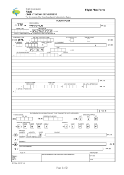
© Copyright 2026