
LABORATORY NITROGEN GAS AND AIR GENERATORS
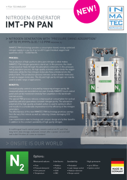
PD-0100-0072
Revision A
LABORATORY NITROGEN GAS
AND AIR GENERATORS
Nitrogen N5P, Nitrogen N600P,
Nitrogen N600P-HC, and A3000P-TOC
Installation, Operation & Maintenance
Manual
Nitrogen Gas and Air Gas Generators
Installation, Operation & Maintenance Manual
Nitrogen and Air Gas Products Family of Laboratory Generators
Installation, Operation & Maintenance Manual
Covering the following laboratory nitrogen and air gas generator models:
Model
Nitrogen N600P
Nitrogen N600P-HC
Nitrogen N5P
Zero Air A3000P-TOC
Proton OnSite
10 Technology Drive
Wallingford, CT 06492
203-949-8697
203-678-2000
[email protected]
www.protononsite.com
© 2014 Proton Energy Systems, Inc. d/b/a Proton OnSite
All rights not expressly granted herein are reserved.
Information in this document is provided in connection with Proton Energy Systems Inc. d/b/a Proton OnSite
(“Proton”) products and services. No license, express or implied, by estoppel or otherwise, to any intellectual
property rights is granted by this document. Except as provided in Proton Terms and Conditions of Sale for
such products and services, Proton assumes no liability whatsoever, and Proton disclaims any express or
implied warranty, whether written or oral, relating to sale and/or use of Proton products or services including
liability or warranties relating to fitness for a particular purpose, merchantability, or infringement of any
patent, copyright or other intellectual property right. Proton products are not intended for use in medical, life
saving, or life sustaining applications.
Proton may make changes to specifications and product descriptions at any time, without notice.
This document as well as any software, processes or procedures described in it is furnished under license
and may only be used or copied in accordance with the terms of the license. The information in this
document is furnished for informational use only, is subject to change without notice, and should not be
construed as a commitment by Proton. Proton assumes no responsibility or liability for any errors or
inaccuracies that may appear in this document or any software that may be provided in association with this
document.
Except as permitted by such license, no part of this document may be reproduced, stored in a retrieval
system, or transmitted in any form or by any means without the express written consent of Proton.
® Proton, Proton OnSite, Proton Energy Systems, the Proton design, StableFlow, StableFlow Hydrogen
Control System and design, HOGEN, and FuelGen are trademarks of Proton Energy Systems, Inc.
Any other brands and/or names used herein are the property of their respective owners.
PD-0100-0072 Rev. A
--UNAUTHORIZED COPIES PROHIBITED--
Page 2 of 32
Nitrogen Gas and Air Gas Generators
Installation, Operation & Maintenance Manual
Purchaser—please record your generator serial and configuration numbers in
this space:
Serial Number ____________________________________________
Configuration Number______________________________________
Disclaimer
Proton OnSite has written this manual to be an easy to use guide for the Laboratory Nitrogen and Air Gas
Generators. All statements, technical information, and recommendations in this manual and in any guides or
related documents are believed reliable, but the accuracy and completeness thereof are not guaranteed or
warranted. They are not intended to be, nor should they be understood to be, representations or warranties
concerning the products described.
This nitrogen gas generator has been sold subject to the limited warranties set forth in the warranty statement.
Further, Proton reserves the right to make changes in the specifications of the products described in this
manual at any time without notice and without obligation to notify any person of such changes.
This laboratory nitrogen generator is designed for operation only by trained personnel familiar with the use of
similar equipment and with safety requirements for the use of nitrogen and other industrial gases. Before
operating this laboratory nitrogen generator, make sure to read and understand this information provided
herein. If you have questions, please contact Proton OnSite or your generator supplier.
PD-0100-0072 Rev. A
--UNAUTHORIZED COPIES PROHIBITED--
Page 3 of 32
Nitrogen Gas and Air Gas Generators
Installation, Operation & Maintenance Manual
LIMITED WARRANTY
NITROGEN AND AIR SYSTEMS
LIMITED WARRANTY: PROTON ENERGY SYSTEMS INC. (“PROTON”) warrants that the ITEMS LISTED BELOW shall
be free from defects in material and workmanship for the stated period of time commencing from date of shipment or as stated below.
N600P, N600P-HC, N5P laboratory nitrogen gas generators:
One (1) year from shipment
Zero Air A3000P, A3000P-TOC laboratory air gas generators:
One (1) year from shipment
Repair or replacement parts for Nitrogen and Air Gas Generator Systems:
Ninety (90) days from shipment
EXCLUDED FROM THIS LIMITED WARRANTY: The following shall be excluded from the Limited Warranty:
·
Parts and items considered consumable in normal operations, including those parts and items supplied with the Nitrogen and Air
Gas Generator Systems (“Systems”) for maintenance.
·
Any System and its parts that are not installed, operated, and maintained in accordance with the unit’s manual supplied with the
System.
·
Damages due to accident, abuse, acts of God, acts of terrorism, misuse or negligence, or which result, in whole or in part, from
improper or unauthorized use or repair of the System, or use of the System in a manner for which it was not designed, or by
causes external to the System such as, but not limited to, power or air conditioning failure or voltage irregularities.
REMEDY: BUYER’S sole and exclusive remedy in the event of defect, and the liability of PROTON hereunder is limited
to the adjustment, repair, or replacement of the defective item or part with a similar item or part free of defect.
Such adjustments, repairs, or replacements will be made at PROTON’S Wallingford, Connecticut, plant or, for Systems only, at the
site of the System, if BUYER so elects. All costs for shipping equipment or parts shall be on the account of the BUYER whether to or
from the point of manufacture. Labor costs associated with travel, expenses, and subsistence costs for field services shall be on the
account of the BUYER.
VOIDING OF THE LIMITED WARRANTY: This Limited Warranty is immediately void upon:
·
THE OPENING OR DISASSEMBLY OF THE SYSTEM CABINET (OR ANY PART THEREIN), OR
·
THE SALE, ASSIGNMENT OR ANY OTHER TRANSFER OF TITLE BY BUYER OF THE ITEMS OR PARTS
OTHERWISE COVERED UNDER THIS LIMITED WARRANTY
WAIVER OF ALL OTHER WARRANTIES: THE LIMITED WARRANTY PROVIDED HEREUNDER AND THE RIGHTS
AND REMEDIES OF THE BUYER HEREUNDER ARE IN LIEU OF, AND BUYER EXPRESSLY WAIVES, ALL OTHER
WARRANTIES, GUARANTEES, OBLIGATIONS, LIABILITIES, OR REMEDIES, EXPRESSED OR IMPLIED, ARISING BY
LAW OR OTHERWISE, INCLUDING WITHOUT LIMITATION IMPLIED WARRANTIES OF MERCHANTABILITY AND
NON-INFRINGEMENT, IMPLIED WARRANTIES ARISING FORM THE COURSE OF DEALING OR USAGE OF TRADE
AND IMPLIED WARRANTIES OF SUITABILITY OR FITNESS FOR A PARTICULAR PURPOSE.
LIMITATION OF LIABILITY: THE REMEDIES PROVIDED IN THIS LIMITED WARRANTY ARE EXCLUSIVE AND
PROTON SHALL IN NO WAY BE LIABLE FOR INCIDENTAL OR CONSEQUENTIAL DAMAGES OF ANY KIND
WHATSOEVER INCLUDING WITHOUT LIMITATION LOSS OF USE, REVENUE OR PROFIT.
PD-0100-0072 Rev. A
--UNAUTHORIZED COPIES PROHIBITED--
Page 4 of 32
Nitrogen Gas and Air Gas Generators
Installation, Operation & Maintenance Manual
Family of Nitrogen Gas and Air Gas of Laboratory Generators
INSTALLATION, OPERATION & MAINTENANCE MANUAL
Prepared by
PROTON ONSITE®
CONTENTS
1
2
Introduction ............................................................................................................ 8
1.1
General Information................................................................................................. 8
1.2
Product Specifications .............................................................................................. 9
Safety .................................................................................................................... 12
2.1
Using Nitrogen Gas................................................................................................. 12
2.2
Oxygen Enrichment ................................................................................................ 12
2.3
Safety Devices ......................................................................................................... 14
2.4
Technical Service Contact Information ................................................................. 14
3
Placement ............................................................................................................. 15
4
Installation ............................................................................................................ 17
4.1
4.1.1
4.1.2
Turn Off External Air Supply before Installing .................................................... 17
4.3
Electrical Connections ............................................................................................ 18
4.4
Pneumatic Connections .......................................................................................... 18
4.5
4.5.1
4.5.2
4.6
6
Remove Unit from Container or Packaging ...................................................................... 17
Stacking Units to Conserve Space and Footprint ............................................................... 17
4.2
4.4.1
4.4.2
4.4.3
5
Set Up and Position Generator............................................................................... 17
Air Inlet ........................................................................................................................... 18
Nitrogen Outlet ................................................................................................................ 19
Condensate Drain ............................................................................................................ 19
Electric Power Supply ............................................................................................ 19
Recommendations for Correct Installation ........................................................................ 19
Connection ...................................................................................................................... 19
Packaging Disposal ................................................................................................. 20
Disassembly and Transport ................................................................................... 21
5.1
Disassembly ............................................................................................................ 21
5.2
Transport ................................................................................................................ 21
5.3
Warnings ................................................................................................................ 21
Operation .............................................................................................................. 22
PD-0100-0072 Rev. A
--UNAUTHORIZED COPIES PROHIBITED--
Page 5 of 32
Nitrogen Gas and Air Gas Generators
Installation, Operation & Maintenance Manual
6.1
Operational Interface ............................................................................................. 22
6.2
Initial Start-Up ....................................................................................................... 24
6.3
Generator Start-Up ................................................................................................ 25
6.4
Nitrogen/Air Production ........................................................................................ 25
6.5
Stop the Generator ................................................................................................. 26
6.6
Parameter Display .................................................................................................. 26
6.6.1
6.6.2
7
8
Product Outlet Pressure Gauge ......................................................................................... 26
Adjusting Gas Delivery Pressure ...................................................................................... 26
Maintenance ......................................................................................................... 27
7.1
Maintenance Counters Display .............................................................................. 27
7.2
Maintenance Schedule ............................................................................................ 28
7.3
Alarms..................................................................................................................... 28
APPENDIX A—FORMS ...................................................................................... 29
8.1
Filter Element Change Log .................................................................................... 29
8.2
Customer Registration Form ................................................................................. 30
TABLE OF FIGURES
FIGURE 1: CABINET DIMENSIONS .............................................................................................................. 11
FIGURE 2: GENERAL ARRANGEMENT—REAR (SHOWING STACKED UNITS ) AND INTERNAL ACCESS ................... 16
FIGURE 3: EXAMPLE OF MOISTURE TRAP ................................................................................................... 18
FIGURE 5: MAIN SCREEN .......................................................................................................................... 22
FIGURE 6: SELECT SCREEN ....................................................................................................................... 22
FIGURE 7: ALARMS SCREEN (TWO EXAMPLES) ............................................................................................. 23
FIGURE 8: MAINTENANCE SCREEN ............................................................................................................. 23
FIGURE 9: VALVE STATUS SCREEN ............................................................................................................. 23
FIGURE 10: CONFIGURATION (OR PASSWORD ) SCREEN ................................................................................ 23
FIGURE 11: ALARM CONFIGURATION SCREEN ............................................................................................. 24
FIGURE 12: FACTORY CONFIGURATION SCREEN ......................................................................................... 24
FIGURE 13: STAND-BY.............................................................................................................................. 24
FIGURE 14: HMI INTERFACE MAIN PAGE................................................................................................... 25
FIGURE 15: START BUTTON ....................................................................................................................... 25
FIGURE 16: NITROGEN PRODUCTION START ............................................................................................... 25
FIGURE 17: NITROGEN PRODUCTION STOP ................................................................................................ 26
FIGURE 18: MENU KEY ........................................................................................................................... 27
FIGURE 19: MAINTENANCE PARAMETERS ................................................................................................... 27
FIGURE 20: MAINTENANCE ....................................................................................................................... 27
LIST OF TABLES
TABLE 1: TECHNICAL SPECIFICATIONS FOR THE FAMILY OF NITROGEN GENERATORS ..................................... 10
TABLE 2: GENERATOR GAS INLET/OUTLET FITTINGS ................................................................................... 11
TABLE 3: OXYGEN CONCENTRATION CALCULATION ..................................................................................... 13
PD-0100-0072 Rev. A
--UNAUTHORIZED COPIES PROHIBITED--
Page 6 of 32
Nitrogen Gas and Air Gas Generators
Installation, Operation & Maintenance Manual
This Installation, Operation & Maintenance Manual of the Nitrogen and Air Generators
uses the following safety symbols and conventions to alert you to information intended to
help you operate your laboratory nitrogen generators correctly and safely.
Manual Conventions
—Indicates a potentially hazardous situation, which, if not avoided, could result in death
or serious injury. The reader is in a situation which could cause bodily injury. Do not
proceed beyond a Warning symbol until the indicated conditions are fully understood and
met.
—Indicates a potentially hazardous situation, which, if not avoided, may result in minor
or moderate injury. It may also be used to alert against unsafe practices. This could result
in equipment damage or loss of data. Do not proceed beyond a Caution symbol until the
indicated conditions are fully understood and met.
—Notes contain helpful suggestions or references.
PD-0100-0072 Rev. A
--UNAUTHORIZED COPIES PROHIBITED--
Page 7 of 32
Nitrogen Gas and Air Gas Generators
Installation, Operation & Maintenance Manual
1
Introduction
The generators are intended to be used as a source of nitrogen and zero air gas for
laboratory applications, including gas chromatography, thermal analysis, ELSD, LCMS,
sample preparation, and so forth.
Proton OnSite has provided these instructions to guide in the installation, operation, and
maintenance of the nitrogen generator. These instructions provide technical product
information, installation requirements, and detailed mechanical interface specifications.
Important safety information is also included in this manual. Please take time to
familiarize yourself with the system and the manual.
This manual attempts to answer most of the frequently asked questions with regards to
the operation of the unit. However, should you have any questions, the Proton OnSite
technical staff stands ready to answer them and support the successful deployment of this
equipment. Please call (203) 949-8697 and ask for field service technical support or email
[email protected]. Please have the part number and configuration
number of your unit available.
IT IS THE CUSTOMER’S RESPONSIBILITY TO CONSULT WITH THE
LOCAL AUTHORITY HAVING JURISDICTION (AHJ) REGARDING LOCAL
CODE REQUIREMENTS FOR INSTALLATION AND OPERATION OF THIS
EQUIPMENT.
DO NOT USE THE NITROGEN GENERATOR IN A MANNER NOT SPECIFIED
BY PROTON ONSITE.
Proton Onsite offers a full range of installation services if you are not comfortable with
installing the nitrogen generator.
1.1 General Information
The laboratory nitrogen and zero air gas generators, when connected to a power source a
feed air source, produce a continuous stream of pressurized nitrogen or air and
automatically maintain a user-set downstream pressure.
This manual covers the installing, operating, and maintaining the nitrogen gas and air gas
generators. The manual assumes the user is familiar with pneumatic circuit components,
and is aware of appropriate safety precautions and use of compressed air and nitrogen
gases.
Detailed technical data are found in Product Specifications (Pg. 9). Dimensions for the
nitrogen or air gas cabinet, or enclosure, are found in Figure 1 (Pg. 11). Required fittings
are displayed in Table 2 (Pg. 11). Ventilation data is found Oxygen Enrichment on page
12.
PD-0100-0072 Rev. A
--UNAUTHORIZED COPIES PROHIBITED--
Page 8 of 32
Nitrogen Gas and Air Gas Generators
Installation, Operation & Maintenance Manual
1.2 Product Specifications
Requirement
NP5
(Nitrogen)
N600P
(Nitrogen)
N600P-HC
(Nitrogen)
Internal Compressors Included
Product Flow rate
A3000P-TOC
(Zero Air)
None
5000 cc/min
600 cc/min
3000 cc/min
Technologies Applied
PSA
Purity
99.999%
<0.10 ppmv
hydrocarbons
99.5%
99.999%
<0.10 ppmv hydrocarbons
Delivery (Output) Pressure, bar
(psi)
0—6.9 bar (0—100 psi)
Oxygen at Max Flow
<10 ppmv
CO2
Input Voltage
≤ 1 ppm
230 VAC ± 10%, 50/60 HZ, Single phase
Particulate ≤ 0.01 μm
Oil vapors ≤ 0.01 mg/m3
Moisture ≤ 3°C (37 ⁰F) dew point
Min pressure 8.5 bar/ 116 psig
Air Input Characteristics
Enclosure Characteristics
External Dimensions
(HxDxW)
Weight
41.5 cm (H) x 54.1 cm (D) x 41.5 cm (W)
16.3" (H) x 21.3" (D) x 16" (W)
49 kg/ 108 lbs
110 lbs / 50 kg
Environmental Considerations
Location - Min/Max Ambient
Operating Temperature
40°F–104°F / 5°C–40°C
Location - Desired Ambient
Operating Temperature1
20–25°C (68–77°F)
Moisture at Max Flow
Location - Max Ambient Humidity
–44°C dew-point STP, < 80 ppm
≤80%
–50°C dewpoint ATP
–60°C dewpoint ATP
≤80%, no condensation
Maximum Level
2000 m (6560 ft) above sea level
Location - Variation from Level
± 3º maximum
Location – Room ventilation
Requirements
Refer to Oxygen Enrichment to determine room ventilation requirements on
page 12.
PD-0100-0072 Rev. A
--UNAUTHORIZED COPIES PROHIBITED--
Page 9 of 32
Nitrogen Gas and Air Gas Generators
Installation, Operation & Maintenance Manual
Requirement
NP5
(Nitrogen)
N600P
(Nitrogen)
N600P-HC
(Nitrogen)
A3000P-TOC
(Zero Air)
Control
Adjustable pressure set-point with manual regulator
Display
Touch-Screen multifunction display, pressure gauge
Environment
Indoor, non-hazardous, non-classified, non-explosive
Additional Features
Stackable
Maintenance Diary
Report Alarms
Accessories
Applied Biosystems Interface
Applications
CC-ICP
GC (Carrier Gas, Make-Up,
ECD), circular dichroism
(refers to the differential
absorption of left and right
circularly polarized light) and
thermal analysis
TOC/GC
Safety
Enclosure Protection
(Ingres Protection Rating)
IP20
Noise
<54 dB (A)
Mechanical Ports
3/8”-Female NPT, with interface kit
Expected yearly operator usage
6000 Hrs
1. Operation time outside desired directly linked to compressor life expectancy.
Table 1: Technical Specifications for the Family of Nitrogen Generators
PD-0100-0072 Rev. A
--UNAUTHORIZED COPIES PROHIBITED--
Page 10 of 32
Nitrogen Gas and Air Gas Generators
Installation, Operation & Maintenance Manual
Figure 1: Cabinet Dimensions
Substance
Flow
Direction
Fitting
Nitrogen
Out
1/4"-Female NPT
Air
In
1/4"-Female NPT
Drain
Out
1/4"-OD Push
Connect
Mating Information
Fitting
Location
Fractional and/or
metric tube adapters
provided
Fractional and/or
metric tube adapters
provided
Tubing Provided
Rear
See Figure 2
Rear
See Figure 2
Rear
See Figure 2
Table 2: Generator Gas Inlet/Outlet Fittings
PD-0100-0072 Rev. A
--UNAUTHORIZED COPIES PROHIBITED--
Page 11 of 32
Nitrogen Gas and Air Gas Generators
Installation, Operation & Maintenance Manual
2
Safety
The safety guidelines below may not cover all situations. If there are concerns or
questions, please contact Proton OnSite Technical Service or check with local authorities.
THIS NITROGEN GENERATOR IS A LABORATORY INSTRUMENT
DESIGNED FOR OPERATION BY TRAINED PERSONNEL. UNSAFE
CONDITIONS MAY RESULT IF THE GENERATOR IS OPERATED BY
UNTRAINED PERSONNEL OR PERSONNEL UNFAMILIAR WITH
NITROGEN AND ENRICHED OXYGEN SAFETY.
ALL PERSONNEL HANDLING, USING OR MAINTAINING THIS
GENERATOR MUST EMPLOY SAFE WORKING PRACTICES AND OBSERVE
ALL RELEVANT LOCAL HEALTH AND SAFETY REGULATIONS.
2.1 Using Nitrogen Gas
Nitrogen is an odorless, colorless nontoxic gas which can displace the air content of the
workspace and increase the risk of asphyxiation if not used properly.
Never directly inhale the gas produced and check gas connections with a liquid leak
detector at initial installation or after a service event where gas plumbing has to be
disconnected.
2.2 Oxygen Enrichment
As a byproduct of the nitrogen production, the generator has the ability to increase the
local oxygen content levels to greater than 23%, thus creating an “oxygen-enriched”
atmosphere if minimum ventilation requirements are not present where the generator is
installed.
To determine if there is enough ventilation, please perform the calculations found in
Table 3 (Pg. 13). The units used should be in cubic feet. For consistency, be sure to use
the same measurement system for all calculations during this process.
The calculation makes a conservative estimate by assuming the following: air input to
nitrogen out is 2:1. The calculation also assumes that the internal pressure swing
“adsorption” (accumulation of gases, liquids, or solutes on the surface of a solid or
liquid.) (PSA) dryer is 100% efficient for removing oxygen from the nitrogen product,
therefore releasing maximum O2 to the environment where the unit is located.
If the air exchange rate of the installation location is unknown, please contact your
laboratory or facilities manager to determine the correct air exchange rate to use in the
calculation.
PD-0100-0072 Rev. A
--UNAUTHORIZED COPIES PROHIBITED--
Page 12 of 32
Nitrogen Gas and Air Gas Generators
Installation, Operation & Maintenance Manual
Calculate room volume:
V: ___________ room volume in cubic feet
Enter air ventilation rate:
R: ___________ room air exchanges per hour
Multiply V x R:
A: ___________
Multiply A x 21%:
B: ___________
Insert values A and B into the equation below to determine potential oxygen enrichment.
If calculated oxygen concentration exceeds 23%, Proton recommends that you improve
or adjust area ventilation, or relocate equipment to a more suitable area.
O2 concentration % =
* 100%
EXAMPLE: A room 10 feet by 12 feet with an 8-foot ceiling has a volume V of 960
cubic feet. If the room ventilation rate R is 4 exchanges per hour, then value A is 3840
and value B is 806. The potential O2 concentration is 21.3%, which is less than the 23%
enriched oxygen threshold value. No changes are needed.
Table 3: Oxygen Concentration Calculation
PD-0100-0072 Rev. A
--UNAUTHORIZED COPIES PROHIBITED--
Page 13 of 32
Nitrogen Gas and Air Gas Generators
Installation, Operation & Maintenance Manual
2.3 Safety Devices
MAXIMUM PRESSURE: A safety valve on each compressor and a safety valve on the
internal air receiving tank prevent the generator pressure from exceeding 12.0 bar (175
psi). The air is vented within the enclosure.
MAXIMUM TEMPERATURE (N600P-HC, and A3000P-TOC versions only): The
unit is fitted with an internal catalyzer, the internal temperature of which is constantly
maintained at 400°C (750°F). To guarantee safety, a completely independent device is
fitted which shuts off power supply to the heating elements if the surface temperature of
the catalyzer exceeds 104°C (220 °F).
2.4 Technical Service Contact Information
Proton OnSite Technical Service can be contacted as follows:
Proton OnSite
10 Technology Drive
Wallingford, CT 06492
203-949-8697
203-678-2000
[email protected]
www.protononsite.com
PD-0100-0072 Rev. A
--UNAUTHORIZED COPIES PROHIBITED--
Page 14 of 32
Nitrogen Gas and Air Gas Generators
Installation, Operation & Maintenance Manual
3
Placement
The nitrogen generator is designed for indoor use only. It should be installed next to the
application it is supplying. If this is not convenient, then the unit can be located
elsewhere; however, pipe lengths should be considered because pressure drops can result
if pipe lengths are too long.
PERFORMANCE OF THE NITROGEN GENERATOR IS AFFECTED BY
AMBIENT CONDITIONS. PROLONGED OPERATION OUTSIDE AMBIENT
TEMPERATURE RANGES SHORTEN THE LIFE OF THE INTERNAL
COMPRESSORS.
Consideration should also be given to the air flow around the unit. An air gap of 6" is
recommended at the rear of the unit. Please see Figure 2 on page 16 for the general
arrangement of the unit.
PD-0100-0072 Rev. A
--UNAUTHORIZED COPIES PROHIBITED--
Page 15 of 32
Nitrogen Gas and Air Gas Generators
Installation, Operation & Maintenance Manual
Figure 2: General Arrangement—Rear (Showing Stacked Units) and Internal Access
PD-0100-0072 Rev. A
--UNAUTHORIZED COPIES PROHIBITED--
Page 16 of 32
Nitrogen Gas and Air Gas Generators
Installation, Operation & Maintenance Manual
4
Installation
4.1 Set Up and Position Generator
The area where the generator is installed must meet the environmental requirements listed
in Product Specifications in Table 1 (Pg. 10).
IN PARTICULAR, CHECK IF VENTILATION IS ADEQUATE. DO NOT
INSTALL THE GENERATOR IN A CLOSED CABINET WITH INSUFFICIENT
VENTILATION. FOR VENTILATION SPECS, REFER TO OXYGEN
ENRICHMENT ON PAGE 12 FOR MINIMUM VENTILATION.
4.1.1 Remove Unit from Container or Packaging
1. Open the packaging from the top and remove the box containing the accessories.
2. Lift the generator by grasping the bottom (two people are needed for this operation)
and set it momentarily on a flat surface.
3. Note that it is recommended that the packaging or container be stored so that the
generator can be returned to the factory for any reason. If the packaging has to be
discarded and the generator needs to be returned to the factory, a charge is assessed
for the shipment of new packaging materials. All returns must be made in the original
packaging or in a Proton OnSite approved substitute.
4. Leave at least 20 cm (6 inches) clearance at the rear panels.
4.1.2 Stacking Units to Conserve Space and Footprint
Stacking units on top of each other (stack no more than 2 units; that is, no more than 3
units high) is a convenient way to save space and to access two different products at the
same time. Figure 2 on page 16 shows a back view of a unit stacked or placed on top of
another. When stacking units, the air compressor should always be placed at the bottom
because of its weight and its tendency to minimally vibrate when operating; however, the
order of how the nitrogen and air units are stacked on top of the air compressor unit is not
important.
In the installation kit, there is a steel plate for securing one unit on top of the other. Four
screws and four lock washers are provided to secure the exterior chassis of the stackable
units together securely in place. You need just a Philips head #2-screwdriver to fasten the
units together. Be sure to get help lifting and stacking the units. Two people are
recommended for this task.
4.2 Turn Off External Air Supply before Installing
Models Nitrogen N5P, N600P, N600P-HC, and A3000P-TOC are designed for using a
source of external compressed air. Refer to Product Specifications (Pg. 9) for the input air
requirements that must be met to prevent equipment damage. It is recommended that the
air supply to the generator be protected from liquid condensation by installing a moisture
PD-0100-0072 Rev. A
--UNAUTHORIZED COPIES PROHIBITED--
Page 17 of 32
Nitrogen Gas and Air Gas Generators
Installation, Operation & Maintenance Manual
trap upstream of the nitrogen generator. The trap should be installed in a manner that it
acts as a drip-leg on the supply of air (an example is shown in Figure 3, below)
To Nitrogen Generator
Figure 3: Example of Moisture Trap
It is also recommended that an air isolation valve be installed up stream of the unit to
allow for safe maintenance.
4.3 Electrical Connections
The input power for these systems is 230 ± 10% VAC power with the provided power
cord at the rear of the unit (See Figure 2, Pg. 16). Ensure the power cord is not in any
passageway and is protected from damage.
4.4 Pneumatic Connections
The pneumatic connections for the nitrogen generator should be plumbed with piping or
tubing suitably rated for the working pressure and flow rates of the gases being used.
4.4.1 Air Inlet
THE COMPRESSED AIR SUPPLY TO THE GENERATOR MAY NOT EXCEED
10.5 BAR (152 PSI).
The air inlet is on rear panel of the nitrogen generator (See Figure 2, Pg. 16). The unit is
equipped with a TBD fitting. Fittings can be provided to adapt this to either a fractional
or metric tube, depending upon your location.
To connect compressed air supply to the generator, locate the compressed air coupling,
marked “AIR INLET” at the rear of the generator, and then connect the line.
PD-0100-0072 Rev. A
--UNAUTHORIZED COPIES PROHIBITED--
Page 18 of 32
Nitrogen Gas and Air Gas Generators
Installation, Operation & Maintenance Manual
4.4.2 Nitrogen Outlet
The nitrogen outlet is on the rear panel of the nitrogen generator (See Figure 2, Pg. 16).
The unit is equipped with a 1/4"-female NPT fitting. Fittings are provided to adapt this to
either a fractional or a metric tube, depending upon your location. The pipe diameter
must be sized on the basis of the acceptable pressure drop values of the utility.
TO ENSURE NOMINAL PURITY OF THE DELIVERED GAS IS MAINTAINED
(MINIMIZE CONTAMINATION FROM OIL RESIDUE, DUST, SCALING AND
HUMIDITY), IT IS RECOMMENDED TO USE CLEAN AND/OR TREATED
PIPELINES FOR FINAL GAS DISTRIBUTION.
To connect to the nitrogen outlet, locate the nitrogen coupling, marked “NITROGEN
OUTLET” at the rear of the generator, and then connect the line.
4.4.3 Condensate Drain
The condensate drain is on the rear of the nitrogen generator (See Figure 2, Pg. 16). The
connection is a 1/4"-OD push-to-connect type fitting.
THE WATER CONDENSATE (CONDENSATION) IS EXPELLED BY BURSTS
OF COMPRESSED AIR THROUGH THE DRAIN HOSE. CHECK THAT THE
DRAIN HOSE IS ADEQUATELY SECURED.
4.5 Electric Power Supply
FOR SAFETY REASONS, THE FOLLOWING INSTRUCTIONS MUST BE
STRICTLY OBSERVED.
THE ELECTRICAL INSTALLATION MUST COMPLY WITH CURRENT
STANDARDS, IN PARTICULAR REGARDING THE PROTECTION
LINE/GROUND WIRE.
4.5.1 Recommendations for Correct Installation
1. Do not use extension leads, adaptors, or multiple sockets.
2. Always connect the protection/ground wire.
3. The mains socket and switch must be located in an easily accessible position.
4. If the provided power cable does not match the local plug configuration, use the
proper power cable with the appropriate configuration before attempting to apply
power to the unit.
4.5.2 Connection
1. Locate power cable connector at the rear of the generator.
2. Before connecting the cable, ensure that the POWER switch is set to OFF.
PD-0100-0072 Rev. A
--UNAUTHORIZED COPIES PROHIBITED--
Page 19 of 32
Nitrogen Gas and Air Gas Generators
Installation, Operation & Maintenance Manual
3. Connect the power cable supplied with the generator.
4.6 Packaging Disposal
It is recommended that the user keeps the packaging in case the generator needs to be
returned to the factory for any reason. If the packaging has to be discarded and the
generator needs to be returned to the factory, a charge is assessed for shipping new
packaging materials. All returns must be made in the original container or in a Proton
OnSite approved substitute.
PD-0100-0072 Rev. A
--UNAUTHORIZED COPIES PROHIBITED--
Page 20 of 32
Nitrogen Gas and Air Gas Generators
Installation, Operation & Maintenance Manual
5
Disassembly and Transport
5.1 Disassembly
1. Stop the generator (Refer to Stop the Generator, Pg. 26).
2. Wait for depressurization (about a minute).
3. Switch off the generator (Refer to Error! Reference source not found., Pg. Error!
Bookmark not defined.).
4. Disconnect the electric power cable.
5. Close all valves (air inlet, tanks) and detach the pneumatic connections.
5.2 Transport
Remember that during transport the generator must always remain in a vertical position.
If conserved, use the original packaging; otherwise use a pallet of adequate dimensions to
hold the generator, affixing instructions in visible locations, such as: THIS WAY UP,
KEEP IN VERTICAL POSITION.
5.3 Warnings
If a failure in gas supply (due to a power failure, activation of an electrical safety device,
or generator fault), even temporary, is not admissible, a pneumatic panel should be
envisaged, to enable provisional activation of a reserve gas source (totally or partially
automatic).
PD-0100-0072 Rev. A
--UNAUTHORIZED COPIES PROHIBITED--
Page 21 of 32
Nitrogen Gas and Air Gas Generators
Installation, Operation & Maintenance Manual
6
Operation
6.1 Operational Interface
The generators are equipped with a pressure gauge, internal, showing product gas
pressure, and a touch screen interface, indicating system status, hours of operation, and
alarms and warnings indicators (Error! Reference source not found., Error! Reference
urce not found.). The first screen is the “Main” screen where the interface introduces
SCREEN SELECT, located at the lower left (Figure 4). Pressing SCREEN SELECT
brings the operator to the “Select” screen where there are 5 menu items to choose from.
To navigate to any screen directly, press the screen-select key; or return to MAIN and
press the screen-select button there. The screens are displayed and defined below.
Operator Interface Display
User’s Screen
Description
Main Screen
Figure 4: Main Screen
Displays keys for standby and operate
modes. Keys for starting, stopping, and
checking system for messages are found
on this screen. A temperature is displayed
for units that have a catalyzer installed.
Pressing the SCREEN SELECT (Figure
5) shows operator equipment menu
options.
System Menu or Select Screen
Presents 8 menu keys that take the
operator to specific screens, including
MAIN, that returns the operator to the
main screen:
Figure 5: Select Screen
PD-0100-0072 Rev. A
6. Main (Figure 4)
7. Alarms (Figure 6)
8. Maintenance (Figure 7)
9. Valve Status (Figure 8)
10. Configuration (Figure 9)
--UNAUTHORIZED COPIES PROHIBITED--
Page 22 of 32
Nitrogen Gas and Air Gas Generators
Installation, Operation & Maintenance Manual
Operator Interface Display
User’s Screen
Description
Alarms Screen
Alarms for Overtemperature (models
Nitrogen N600P-HC and Air A3000PTOC ONLY)
Alarms for high and low system pressure
are displayed here
Figure 6: Alarms Screen (two examples)
Maintenance Screen
Every 2000 hours of logged operation a
maintenance message will come up on
the display to remind that service is
needed.
Figure 7: Maintenance Screen
Refer to Section Error! Reference
source not found. for Maintenance items
Valve Status Screen
This screen shows the valve status as the
PSA operates through the cycle
Figure 8: Valve Status Screen
Configuration (or Password) Screen
11. Alarm Configuration (Figure 10)
12. Factory Configuration (Figure 11)
Figure 9: Configuration (or Password) Screen
PD-0100-0072 Rev. A
--UNAUTHORIZED COPIES PROHIBITED--
Page 23 of 32
Nitrogen Gas and Air Gas Generators
Installation, Operation & Maintenance Manual
Operator Interface Display
User’s Screen
Description
Alarm Configuration Screen
Requires Password
The parameters set on this screen are set
at the factory and should not be changed.
Product Standby (on) is the pressure
where the unit enters standby
Figure 10: Alarm Configuration Screen
Product Tank Standby (off) is where
the unit begins to generate gas again to
replenish the internal receiver
PASSWORD: 2222
Factory Configuration Screen
Requires Password
The parameters set on this screen are set
at the factory and should not be changed.
Figure 11: Factory Configuration Screen
6.2 Initial Start-Up
1. Check that all connections are made as specified in Installation (Pg. 17).
2. Close the nitrogen line down-line from the generator.
3. Switch on the generator, by setting the POWER switch to ON (Refer to Generator
Start-Up, Pg. 25).
4. Start nitrogen production by pressing the START key in Nitrogen/Air Production
(Pg. 25).
5. Wait approximately 15-25 minutes, until the generator reaches the Stand-By status. In
this state, the generator suspends normal production and displays the following
(Figure 12):
Figure 12: Stand-By
PD-0100-0072 Rev. A
--UNAUTHORIZED COPIES PROHIBITED--
Page 24 of 32
Nitrogen Gas and Air Gas Generators
Installation, Operation & Maintenance Manual
From this point the nitrogen is available for the line, by opening the valve closed in
Point 2.
For Models N600P-HC and A3000P-TOC, it is suggested to supply gas to the application
only when the catalyzer has reached the operating temperature (approx 45 minutes after
switch ON).
WARNING: ON INITIAL START-UP, THE INTERNAL NITROGEN STORAGE
TANK INITIALLY CONTAINS AIR. FOR THIS REASON, THE LINE SHOULD
BE VENTED WITH THE GAS (FOR APPROX. 60 MINUTES) BEFORE
EMPLOYING THE NITROGEN FOR THE APPLICATION UTILITY.
6.3 Generator Start-Up
1. Power on the generator by using the switch at the rear of the unit. The unit will boot
up and bring you to the main page of the HMI interface.
Figure 13: HMI Interface Main Page
6.4 Nitrogen/Air Production
1. To start production, press the operation key START (Figure 14):
Figure 14: Start Button
The production screen appears (Figure 15):
Figure 15: Nitrogen Production Start
PD-0100-0072 Rev. A
--UNAUTHORIZED COPIES PROHIBITED--
Page 25 of 32
Nitrogen Gas and Air Gas Generators
Installation, Operation & Maintenance Manual
6.5 Stop the Generator
At any time during production the generator can be stopped by pressing the key NORM
STOP (Figure 16).
Figure 16: Nitrogen Production Stop
The generator ceases stops the process for the PSA beds and everything remains
pressurized for the next use as long as there is no demand for nitrogen or air from the
system.
Avoid turning off the generator directly, without first stopping the production as
described in Stop the Generator, Pg. 26.
6.6 Parameter Display
6.6.1 Product Outlet Pressure Gauge
The pressure in the outlet line is visible on the pressure gauge that is installed on the line
regulator just behind the front cover of the generator
6.6.2 Adjusting Gas Delivery Pressure
2. Pull the pressure regulator knob out to release it.
3. Set the pressure by turning the knob clockwise to increase, counterclockwise to
decrease it. The product pressure will be indicated on the gauge. The regulator is also
a self venting types so changes in pressure set point regardless of up or down are seen
on the gauge with any adjustments
4. Lock the knob by pressing it down.
PD-0100-0072 Rev. A
--UNAUTHORIZED COPIES PROHIBITED--
Page 26 of 32
Nitrogen Gas and Air Gas Generators
Installation, Operation & Maintenance Manual
7
Maintenance
The maintenance operations required on the generator are listed in
Maintenance Schedule (Pg. 28).
7.1 Maintenance Counters Display
1. From the Main Screen Press the SCREEN SELECT key (Figure 17):
Figure 17: MENU Key
2. Then press MAINT. (Figure 18):
Figure 18: Maintenance Parameters
The following page is displayed (Figure 19):
Figure 19: Maintenance
When the maintenance reminder goes off it is in this location that the reminder can be
reset. Be sure to keep track of the date and hours of operation of when the maintenance
tasks were performed.
PD-0100-0072 Rev. A
--UNAUTHORIZED COPIES PROHIBITED--
Page 27 of 32
Nitrogen Gas and Air Gas Generators
Installation, Operation & Maintenance Manual
7.2 Maintenance Schedule
To maintain generator efficiency and reduce the risks of faults, strictly observe the
recommended maintenance schedule.
Behind the front cover of the generator, there is a filter within a clear housing upstream
of the line regulator. This element should be changed at a minimum of every 4000 hours
of operation or no more than 6 months of operation, whichever occurs first. There is an
annual filter kit available for these generators. Please call Customer Service and
reference Annual Kit P/N: KT-1000-0017.
There are no other maintenance items associated with these generators
7.3 Alarms
The generator informs about a malfunction or the necessity of intervention by triggering
an alarm message.
The alarms for these generators are minimized to one of three alarms.
System Pressure Low
System Pressure High
Thermal error (N600P-HC and Air A3000P-TOC ONLY)
The thermal alarm in this unit is triggered when the thermal switch located on the
catalytic burner assembly has opened due to a thermal overload detected at the surface of
the catalytic burner assembly. Check that the ventilation fan is operating and that there is
adequate air flow through the enclosure. Check for blocked vents and make sure the unit
is installed within the installation guidelines.
The System Pressure low and high alarms are triggered by the gas usage and is dependent
upon the setpoints that are user defined at the alarm configuration screen. The low alarm
should be set to a value that is slightly lower than the pressure set on the product pressure
gauge with the regulator. If this alarm activates, the gas demand is exceeding the
generator rating.
The System pressure high alarm should be set to a value that is slightly higher than the
Standby (on) pressure that can be set on the same alarm screen.
PD-0100-0072 Rev. A
--UNAUTHORIZED COPIES PROHIBITED--
Page 28 of 32
Nitrogen Gas and Air Gas Generators
Installation, Operation & Maintenance Manual
8
APPENDIX A—FORMS
8.1 Filter Element Change Log
Use the form below to record the coalescing and carbon filter element change out dates.
The recommended change interval is six months for all elements.
Coalescing Element
PD-0100-0072 Rev. A
Change-Out Dates/ HOURS
--UNAUTHORIZED COPIES PROHIBITED--
Page 29 of 32
Nitrogen Gas and Air Gas Generators
Installation, Operation & Maintenance Manual
8.2 Customer Registration Form
Please fill out the form on the last page, remove it from the manual, and fax it to Proton
OnSite (Fax Number: 1-203-949-8016) to ensure your nitrogen generator is properly
registered. The form may also be sent by mail to the following address:
Customer Service
Proton OnSite
10 Technology Drive
Wallingford, CT 06492
PD-0100-0072 Rev. A
--UNAUTHORIZED COPIES PROHIBITED--
Page 30 of 32
Nitrogen Gas and Air Gas Generators
Installation, Operation & Maintenance Manual
This page is left intentionally blank.
PD-0100-0072 Rev. A
--UNAUTHORIZED COPIES PROHIBITED--
Page 31 of 32
Nitrogen Gas and Air Gas Generators
Installation, Operation & Maintenance Manual
CUSTOMER REGISTRATION FORM
LCMS [Should this be written as LC-MS E?] Laboratory Nitrogen Generator
Generator Model Name?
Generator Serial Number?
From what supplier did you purchase the
generator?
Name of your company?
Company website address?
The application for your nitrogen generator?
Your name?
Your title?
Your phone number with country code?
Your fax number with country code?
Your e-mail address?
The place where the generator is located (city,
state, country)
Are you the person responsible for the
operation of the nitrogen generator?
Do you have any questions at this time that
you need Proton OnSite to answer?
PD-0100-0072 Rev. A
--UNAUTHORIZED COPIES PROHIBITED--
Page 32 of 32


© Copyright 2026