
IBM zEnterprise (zNext) Technical Guide
Front cover Draft Document for Review January 19, 2015 4:52 am SG24-8251-00 IBM z13 Technical Guide Octavian Lascu Erik Bakker Hans-Peter Eckam Steven LaFalce Ewerson Palacio Rakesh Krishnakumar Lourenço Luitgards Moura Neto Maurício Andozia Nogueira Frank Packheiser Giancarlo Rodolfi Andre Spahni Redbooks Draft Document for Review January 19, 2015 4:52 am 8251edno.fm International Technical Support Organization IBM z13 Technical Guide January 2015 SG24-8251-00 8251edno.fm Draft Document for Review January 19, 2015 4:52 am Note: Before using this information and the product it supports, read the information in “Notices” on page xvii. First Edition (January 2015) This edition applies to IBM z Systems™ : IBM z13™, IBM zEnterprise EC12 (zEC12), IBM zEnterprise BC12 (zBC12), IBM zEnterprise 196 (z196), and IBM zEnterprise 114 (z114). This document was created or updated on January 19, 2015. © Copyright International Business Machines Corporation 2015. All rights reserved. Note to U.S. Government Users Restricted Rights -- Use, duplication or disclosure restricted by GSA ADP Schedule Contract with IBM Corp. Draft Document for Review January 19, 2015 4:52 am 8251edno.fm iii 8251edno.fm iv IBM z13 Technical Guide Draft Document for Review January 19, 2015 4:52 am Draft Document for Review January 19, 2015 4:52 am 8251TOC.fm Contents Notices . . . . . . . . . . . . . . . . . . . . . . . . . . . . . . . . . . . . . . . . . . . . . . . . . . . . . . . . . . . . . . . . xvii Trademarks . . . . . . . . . . . . . . . . . . . . . . . . . . . . . . . . . . . . . . . . . . . . . . . . . . . . . . . . . . . . xviii Preface . . . . . . . . . . . . . . . . . . . . . . . . . . . . . . . . . . . . . . . . . . . . . . . . . . . . . . . . . . . . . . . . xix Authors . . . . . . . . . . . . . . . . . . . . . . . . . . . . . . . . . . . . . . . . . . . . . . . . . . . . . . . . . . . . . . . . . xix Now you can become a published author, too! . . . . . . . . . . . . . . . . . . . . . . . . . . . . . . . . . . xxii Comments welcome. . . . . . . . . . . . . . . . . . . . . . . . . . . . . . . . . . . . . . . . . . . . . . . . . . . . . . . xxii Stay connected to IBM Redbooks . . . . . . . . . . . . . . . . . . . . . . . . . . . . . . . . . . . . . . . . . . . . xxii Chapter 1. Introducing the IBM z13 . . . . . . . . . . . . . . . . . . . . . . . . . . . . . . . . . . . . . . . . . . 1 1.1 z13 highlights . . . . . . . . . . . . . . . . . . . . . . . . . . . . . . . . . . . . . . . . . . . . . . . . . . . . . . . . . 4 1.1.1 Processor and memory . . . . . . . . . . . . . . . . . . . . . . . . . . . . . . . . . . . . . . . . . . . . . . 4 1.1.2 Capacity and performance . . . . . . . . . . . . . . . . . . . . . . . . . . . . . . . . . . . . . . . . . . . 5 1.1.3 I/O subsystem and I/O features . . . . . . . . . . . . . . . . . . . . . . . . . . . . . . . . . . . . . . . 6 1.1.4 Virtualization . . . . . . . . . . . . . . . . . . . . . . . . . . . . . . . . . . . . . . . . . . . . . . . . . . . . . . 9 1.1.5 Reliability, availability, and serviceability design . . . . . . . . . . . . . . . . . . . . . . . . . . 10 1.2 z13 technical overview . . . . . . . . . . . . . . . . . . . . . . . . . . . . . . . . . . . . . . . . . . . . . . . . . 10 1.2.1 Models . . . . . . . . . . . . . . . . . . . . . . . . . . . . . . . . . . . . . . . . . . . . . . . . . . . . . . . . . 11 1.2.2 Model upgrade paths . . . . . . . . . . . . . . . . . . . . . . . . . . . . . . . . . . . . . . . . . . . . . . 12 1.2.3 Frames . . . . . . . . . . . . . . . . . . . . . . . . . . . . . . . . . . . . . . . . . . . . . . . . . . . . . . . . . 13 1.2.4 CPC drawer . . . . . . . . . . . . . . . . . . . . . . . . . . . . . . . . . . . . . . . . . . . . . . . . . . . . . 14 1.2.5 I/O connectivity: PCIe and InfiniBand . . . . . . . . . . . . . . . . . . . . . . . . . . . . . . . . . . 16 1.2.6 I/O subsystems . . . . . . . . . . . . . . . . . . . . . . . . . . . . . . . . . . . . . . . . . . . . . . . . . . . 17 1.2.7 Coupling and Server Time Protocol connectivity . . . . . . . . . . . . . . . . . . . . . . . . . 20 1.2.8 Special-purpose features . . . . . . . . . . . . . . . . . . . . . . . . . . . . . . . . . . . . . . . . . . . 22 1.2.9 Reliability, availability, and serviceability. . . . . . . . . . . . . . . . . . . . . . . . . . . . . . . . 25 1.3 Hardware Management Consoles and Support Elements . . . . . . . . . . . . . . . . . . . . . . 25 1.4 IBM z BladeCenter Extension (zBX) Model 004 . . . . . . . . . . . . . . . . . . . . . . . . . . . . . . 26 1.4.1 Blades . . . . . . . . . . . . . . . . . . . . . . . . . . . . . . . . . . . . . . . . . . . . . . . . . . . . . . . . . . 26 1.4.2 IBM WebSphere DataPower Integration Appliance XI50 for zEnterprise . . . . . . . 27 1.5 IBM z Unified Resource Manager . . . . . . . . . . . . . . . . . . . . . . . . . . . . . . . . . . . . . . . . . 27 1.6 Operating systems and software. . . . . . . . . . . . . . . . . . . . . . . . . . . . . . . . . . . . . . . . . . 28 1.6.1 Supported operating systems . . . . . . . . . . . . . . . . . . . . . . . . . . . . . . . . . . . . . . . . 28 1.6.2 IBM compilers . . . . . . . . . . . . . . . . . . . . . . . . . . . . . . . . . . . . . . . . . . . . . . . . . . . . 29 © Copyright IBM Corp. 2015. All rights reserved. v 8251TOC.fm Draft Document for Review January 19, 2015 4:52 am Chapter 2. Central processor complex (CPC) hardware components . . . . . . . . . . . . . 2.1 Frames and drawers . . . . . . . . . . . . . . . . . . . . . . . . . . . . . . . . . . . . . . . . . . . . . . . . . . . 2.1.1 A Frame . . . . . . . . . . . . . . . . . . . . . . . . . . . . . . . . . . . . . . . . . . . . . . . . . . . . . . . . 2.1.2 Z Frame . . . . . . . . . . . . . . . . . . . . . . . . . . . . . . . . . . . . . . . . . . . . . . . . . . . . . . . . 2.1.3 z13 new rear cover (door) design . . . . . . . . . . . . . . . . . . . . . . . . . . . . . . . . . . . . . 2.1.4 I/O drawer and PCIe I/O drawer . . . . . . . . . . . . . . . . . . . . . . . . . . . . . . . . . . . . . . 2.1.5 Top exit I/O cabling . . . . . . . . . . . . . . . . . . . . . . . . . . . . . . . . . . . . . . . . . . . . . . . . 2.2 CPC drawer. . . . . . . . . . . . . . . . . . . . . . . . . . . . . . . . . . . . . . . . . . . . . . . . . . . . . . . . . . 2.2.1 CPC drawer interconnect topology . . . . . . . . . . . . . . . . . . . . . . . . . . . . . . . . . . . . 2.2.2 Oscillator . . . . . . . . . . . . . . . . . . . . . . . . . . . . . . . . . . . . . . . . . . . . . . . . . . . . . . . . 2.2.3 System control . . . . . . . . . . . . . . . . . . . . . . . . . . . . . . . . . . . . . . . . . . . . . . . . . . . 2.2.4 CPC drawer power . . . . . . . . . . . . . . . . . . . . . . . . . . . . . . . . . . . . . . . . . . . . . . . . 2.3 Single chip modules . . . . . . . . . . . . . . . . . . . . . . . . . . . . . . . . . . . . . . . . . . . . . . . . . . . 2.3.1 Processor unit (PU) chip . . . . . . . . . . . . . . . . . . . . . . . . . . . . . . . . . . . . . . . . . . . . 2.3.2 Processor unit (core). . . . . . . . . . . . . . . . . . . . . . . . . . . . . . . . . . . . . . . . . . . . . . . 2.3.3 PU characterization. . . . . . . . . . . . . . . . . . . . . . . . . . . . . . . . . . . . . . . . . . . . . . . . 2.3.4 Storage control (SC) chip . . . . . . . . . . . . . . . . . . . . . . . . . . . . . . . . . . . . . . . . . . . 2.3.5 Cache level structure . . . . . . . . . . . . . . . . . . . . . . . . . . . . . . . . . . . . . . . . . . . . . . 2.4 Memory . . . . . . . . . . . . . . . . . . . . . . . . . . . . . . . . . . . . . . . . . . . . . . . . . . . . . . . . . . . . . 2.4.1 Memory subsystem topology . . . . . . . . . . . . . . . . . . . . . . . . . . . . . . . . . . . . . . . . 2.4.2 Redundant array of independent memory. . . . . . . . . . . . . . . . . . . . . . . . . . . . . . . 2.4.3 Memory configurations . . . . . . . . . . . . . . . . . . . . . . . . . . . . . . . . . . . . . . . . . . . . . 2.4.4 Memory upgrades . . . . . . . . . . . . . . . . . . . . . . . . . . . . . . . . . . . . . . . . . . . . . . . . . 2.4.5 Drawer replacement and memory. . . . . . . . . . . . . . . . . . . . . . . . . . . . . . . . . . . . . 2.4.6 Flexible Memory Option . . . . . . . . . . . . . . . . . . . . . . . . . . . . . . . . . . . . . . . . . . . . 2.4.7 Pre-planned memory . . . . . . . . . . . . . . . . . . . . . . . . . . . . . . . . . . . . . . . . . . . . . . 2.5 Reliability, availability, and serviceability. . . . . . . . . . . . . . . . . . . . . . . . . . . . . . . . . . . . 2.5.1 RAS in the CPC memory subsystem . . . . . . . . . . . . . . . . . . . . . . . . . . . . . . . . . . 2.5.2 General zEC12 RAS features . . . . . . . . . . . . . . . . . . . . . . . . . . . . . . . . . . . . . . . . 2.6 Connectivity. . . . . . . . . . . . . . . . . . . . . . . . . . . . . . . . . . . . . . . . . . . . . . . . . . . . . . . . . . 2.6.1 Redundant I/O interconnect . . . . . . . . . . . . . . . . . . . . . . . . . . . . . . . . . . . . . . . . . 2.6.2 Enhanced drawer availability . . . . . . . . . . . . . . . . . . . . . . . . . . . . . . . . . . . . . . . . 2.6.3 CPC drawer upgrade . . . . . . . . . . . . . . . . . . . . . . . . . . . . . . . . . . . . . . . . . . . . . . 2.7 Model configurations . . . . . . . . . . . . . . . . . . . . . . . . . . . . . . . . . . . . . . . . . . . . . . . . . . . 2.7.1 Upgrades . . . . . . . . . . . . . . . . . . . . . . . . . . . . . . . . . . . . . . . . . . . . . . . . . . . . . . . 2.7.2 Concurrent PU conversions . . . . . . . . . . . . . . . . . . . . . . . . . . . . . . . . . . . . . . . . . 2.7.3 Model capacity identifier . . . . . . . . . . . . . . . . . . . . . . . . . . . . . . . . . . . . . . . . . . . . 2.7.4 Model capacity identifier and MSU value . . . . . . . . . . . . . . . . . . . . . . . . . . . . . . . 2.7.5 Capacity Backup . . . . . . . . . . . . . . . . . . . . . . . . . . . . . . . . . . . . . . . . . . . . . . . . . . 2.7.6 On/Off Capacity on Demand and CPs . . . . . . . . . . . . . . . . . . . . . . . . . . . . . . . . . 2.8 Power and cooling. . . . . . . . . . . . . . . . . . . . . . . . . . . . . . . . . . . . . . . . . . . . . . . . . . . . . 2.8.1 Power consumption . . . . . . . . . . . . . . . . . . . . . . . . . . . . . . . . . . . . . . . . . . . . . . . 2.8.2 High Voltage Direct Current power feature . . . . . . . . . . . . . . . . . . . . . . . . . . . . . . 2.8.3 Internal Battery Feature . . . . . . . . . . . . . . . . . . . . . . . . . . . . . . . . . . . . . . . . . . . . 2.8.4 Power capping and saving . . . . . . . . . . . . . . . . . . . . . . . . . . . . . . . . . . . . . . . . . . 2.8.5 Power estimation tool . . . . . . . . . . . . . . . . . . . . . . . . . . . . . . . . . . . . . . . . . . . . . . 2.8.6 Cooling . . . . . . . . . . . . . . . . . . . . . . . . . . . . . . . . . . . . . . . . . . . . . . . . . . . . . . . . . 2.8.7 Radiator Unit . . . . . . . . . . . . . . . . . . . . . . . . . . . . . . . . . . . . . . . . . . . . . . . . . . . . . 2.8.8 Water-cooling unit . . . . . . . . . . . . . . . . . . . . . . . . . . . . . . . . . . . . . . . . . . . . . . . . . 2.9 Summary of z13 structure . . . . . . . . . . . . . . . . . . . . . . . . . . . . . . . . . . . . . . . . . . . . . . . 31 32 33 34 34 34 35 36 39 40 41 42 43 45 47 48 49 50 50 52 52 53 57 57 57 58 59 60 60 61 62 64 65 65 66 67 68 69 69 72 72 72 73 74 74 74 75 76 78 80 Chapter 3. Central processor complex system design . . . . . . . . . . . . . . . . . . . . . . . . . 83 3.1 Overview . . . . . . . . . . . . . . . . . . . . . . . . . . . . . . . . . . . . . . . . . . . . . . . . . . . . . . . . . . . . 84 vi IBM z13 Technical Guide Draft Document for Review January 19, 2015 4:52 am 8251TOC.fm 3.2 Design highlights . . . . . . . . . . . . . . . . . . . . . . . . . . . . . . . . . . . . . . . . . . . . . . . . . . . . . . 84 3.3 CPC drawer design . . . . . . . . . . . . . . . . . . . . . . . . . . . . . . . . . . . . . . . . . . . . . . . . . . . . 85 3.3.1 Cache levels and memory structure . . . . . . . . . . . . . . . . . . . . . . . . . . . . . . . . . . . 86 3.3.2 CPC drawer interconnect topology . . . . . . . . . . . . . . . . . . . . . . . . . . . . . . . . . . . . 89 3.4 Processor unit design . . . . . . . . . . . . . . . . . . . . . . . . . . . . . . . . . . . . . . . . . . . . . . . . . . 90 3.4.1 Simultaneous multithreading. . . . . . . . . . . . . . . . . . . . . . . . . . . . . . . . . . . . . . . . . 91 3.4.2 Single instruction multiple data (SIMD) . . . . . . . . . . . . . . . . . . . . . . . . . . . . . . . . . 92 3.4.3 Out-of-order (OOO) execution . . . . . . . . . . . . . . . . . . . . . . . . . . . . . . . . . . . . . . . 94 3.4.4 Superscalar processor . . . . . . . . . . . . . . . . . . . . . . . . . . . . . . . . . . . . . . . . . . . . . 96 3.4.5 Compression and cryptography accelerators on a chip . . . . . . . . . . . . . . . . . . . . 97 3.4.6 Decimal floating point accelerator . . . . . . . . . . . . . . . . . . . . . . . . . . . . . . . . . . . . . 98 3.4.7 IEEE floating point . . . . . . . . . . . . . . . . . . . . . . . . . . . . . . . . . . . . . . . . . . . . . . . . 99 3.4.8 Processor error detection and recovery . . . . . . . . . . . . . . . . . . . . . . . . . . . . . . . . 99 3.4.9 Branch prediction . . . . . . . . . . . . . . . . . . . . . . . . . . . . . . . . . . . . . . . . . . . . . . . . . 99 3.4.10 Wild branch . . . . . . . . . . . . . . . . . . . . . . . . . . . . . . . . . . . . . . . . . . . . . . . . . . . . 100 3.4.11 Translation lookaside buffer . . . . . . . . . . . . . . . . . . . . . . . . . . . . . . . . . . . . . . . 100 3.4.12 Instruction fetching, decoding, and grouping . . . . . . . . . . . . . . . . . . . . . . . . . . 100 3.4.13 Extended Translation Facility . . . . . . . . . . . . . . . . . . . . . . . . . . . . . . . . . . . . . . 101 3.4.14 Instruction set extensions . . . . . . . . . . . . . . . . . . . . . . . . . . . . . . . . . . . . . . . . . 101 3.4.15 Transactional execution . . . . . . . . . . . . . . . . . . . . . . . . . . . . . . . . . . . . . . . . . . 101 3.4.16 Runtime instrumentation . . . . . . . . . . . . . . . . . . . . . . . . . . . . . . . . . . . . . . . . . . 102 3.5 Processor unit functions . . . . . . . . . . . . . . . . . . . . . . . . . . . . . . . . . . . . . . . . . . . . . . . 102 3.5.1 Overview . . . . . . . . . . . . . . . . . . . . . . . . . . . . . . . . . . . . . . . . . . . . . . . . . . . . . . . 102 3.5.2 Central processors . . . . . . . . . . . . . . . . . . . . . . . . . . . . . . . . . . . . . . . . . . . . . . . 103 3.5.3 Integrated Facility for Linux . . . . . . . . . . . . . . . . . . . . . . . . . . . . . . . . . . . . . . . . . 104 3.5.4 Internal Coupling Facility. . . . . . . . . . . . . . . . . . . . . . . . . . . . . . . . . . . . . . . . . . . 105 3.5.5 z Systems Integrated Information Processor (zIIP). . . . . . . . . . . . . . . . . . . . . . . 106 3.5.6 System assist processors . . . . . . . . . . . . . . . . . . . . . . . . . . . . . . . . . . . . . . . . . . 111 3.5.7 Reserved processors . . . . . . . . . . . . . . . . . . . . . . . . . . . . . . . . . . . . . . . . . . . . . 111 3.5.8 Integrated firmware processor . . . . . . . . . . . . . . . . . . . . . . . . . . . . . . . . . . . . . . 112 3.5.9 Processor unit assignment . . . . . . . . . . . . . . . . . . . . . . . . . . . . . . . . . . . . . . . . . 112 3.5.10 Sparing rules . . . . . . . . . . . . . . . . . . . . . . . . . . . . . . . . . . . . . . . . . . . . . . . . . . . 113 3.5.11 Increased flexibility with z/VM mode partitions . . . . . . . . . . . . . . . . . . . . . . . . . 113 3.6 Memory design . . . . . . . . . . . . . . . . . . . . . . . . . . . . . . . . . . . . . . . . . . . . . . . . . . . . . . 114 3.6.1 Overview . . . . . . . . . . . . . . . . . . . . . . . . . . . . . . . . . . . . . . . . . . . . . . . . . . . . . . . 114 3.6.2 Central storage . . . . . . . . . . . . . . . . . . . . . . . . . . . . . . . . . . . . . . . . . . . . . . . . . . 116 3.6.3 Expanded storage . . . . . . . . . . . . . . . . . . . . . . . . . . . . . . . . . . . . . . . . . . . . . . . . 116 3.6.4 Hardware system area . . . . . . . . . . . . . . . . . . . . . . . . . . . . . . . . . . . . . . . . . . . . 117 3.7 Logical partitioning . . . . . . . . . . . . . . . . . . . . . . . . . . . . . . . . . . . . . . . . . . . . . . . . . . . 118 3.7.1 Overview . . . . . . . . . . . . . . . . . . . . . . . . . . . . . . . . . . . . . . . . . . . . . . . . . . . . . . . 118 3.7.2 Storage operations . . . . . . . . . . . . . . . . . . . . . . . . . . . . . . . . . . . . . . . . . . . . . . . 125 3.7.3 Reserved storage . . . . . . . . . . . . . . . . . . . . . . . . . . . . . . . . . . . . . . . . . . . . . . . . 128 3.7.4 Logical partition storage granularity . . . . . . . . . . . . . . . . . . . . . . . . . . . . . . . . . . 128 3.7.5 LPAR dynamic storage reconfiguration. . . . . . . . . . . . . . . . . . . . . . . . . . . . . . . . 129 3.8 Intelligent Resource Director . . . . . . . . . . . . . . . . . . . . . . . . . . . . . . . . . . . . . . . . . . . . 130 3.9 Clustering technology . . . . . . . . . . . . . . . . . . . . . . . . . . . . . . . . . . . . . . . . . . . . . . . . . 131 3.9.1 Coupling Facility Control Code . . . . . . . . . . . . . . . . . . . . . . . . . . . . . . . . . . . . . . 132 3.9.2 Coupling Thin Interrupts . . . . . . . . . . . . . . . . . . . . . . . . . . . . . . . . . . . . . . . . . . . 134 3.9.3 Dynamic CF dispatching . . . . . . . . . . . . . . . . . . . . . . . . . . . . . . . . . . . . . . . . . . . 134 3.9.4 CFCC and Flash Express use. . . . . . . . . . . . . . . . . . . . . . . . . . . . . . . . . . . . . . . 135 Chapter 4. Central processor complex I/O system structure . . . . . . . . . . . . . . . . . . . 137 4.1 Introduction to the InfiniBand and PCIe for I/O infrastructure . . . . . . . . . . . . . . . . . . . 138 Contents vii 8251TOC.fm viii Draft Document for Review January 19, 2015 4:52 am 4.1.1 InfiniBand specifications . . . . . . . . . . . . . . . . . . . . . . . . . . . . . . . . . . . . . . . . . . . 4.1.2 PCIe Generation 3 . . . . . . . . . . . . . . . . . . . . . . . . . . . . . . . . . . . . . . . . . . . . . . . 4.2 I/O system overview . . . . . . . . . . . . . . . . . . . . . . . . . . . . . . . . . . . . . . . . . . . . . . . . . . 4.2.1 Characteristics . . . . . . . . . . . . . . . . . . . . . . . . . . . . . . . . . . . . . . . . . . . . . . . . . . 4.2.2 Summary of supported I/O features . . . . . . . . . . . . . . . . . . . . . . . . . . . . . . . . . . 4.3 I/O drawer . . . . . . . . . . . . . . . . . . . . . . . . . . . . . . . . . . . . . . . . . . . . . . . . . . . . . . . . . . 4.4 PCIe I/O drawer . . . . . . . . . . . . . . . . . . . . . . . . . . . . . . . . . . . . . . . . . . . . . . . . . . . . . 4.5 PCIe I/O drawer and I/O drawer offerings . . . . . . . . . . . . . . . . . . . . . . . . . . . . . . . . . . 4.6 Fanouts . . . . . . . . . . . . . . . . . . . . . . . . . . . . . . . . . . . . . . . . . . . . . . . . . . . . . . . . . . . . 4.6.1 PCIe Generation 3 fanout (FC 0173) . . . . . . . . . . . . . . . . . . . . . . . . . . . . . . . . . 4.6.2 HCA2-C fanout (FC 0162). . . . . . . . . . . . . . . . . . . . . . . . . . . . . . . . . . . . . . . . . . 4.6.3 Integrated Coupling Adapter (FC 0172) . . . . . . . . . . . . . . . . . . . . . . . . . . . . . . . 4.6.4 HCA3-O (12x IFB) fanout (FC 0171). . . . . . . . . . . . . . . . . . . . . . . . . . . . . . . . . . 4.6.5 HCA3-O LR (1x IFB) fanout (FC 0170) . . . . . . . . . . . . . . . . . . . . . . . . . . . . . . . . 4.6.6 Fanout considerations. . . . . . . . . . . . . . . . . . . . . . . . . . . . . . . . . . . . . . . . . . . . . 4.7 I/O features (cards) . . . . . . . . . . . . . . . . . . . . . . . . . . . . . . . . . . . . . . . . . . . . . . . . . . . 4.7.1 I/O feature card ordering information . . . . . . . . . . . . . . . . . . . . . . . . . . . . . . . . . 4.7.2 PCHID report . . . . . . . . . . . . . . . . . . . . . . . . . . . . . . . . . . . . . . . . . . . . . . . . . . . 4.8 Connectivity. . . . . . . . . . . . . . . . . . . . . . . . . . . . . . . . . . . . . . . . . . . . . . . . . . . . . . . . . 4.8.1 I/O feature support and configuration rules. . . . . . . . . . . . . . . . . . . . . . . . . . . . . 4.8.2 FICON channels . . . . . . . . . . . . . . . . . . . . . . . . . . . . . . . . . . . . . . . . . . . . . . . . . 4.8.3 OSA-Express5S . . . . . . . . . . . . . . . . . . . . . . . . . . . . . . . . . . . . . . . . . . . . . . . . . 4.8.4 OSA-Express4S features . . . . . . . . . . . . . . . . . . . . . . . . . . . . . . . . . . . . . . . . . . 4.8.5 OSA-Express for ensemble connectivity. . . . . . . . . . . . . . . . . . . . . . . . . . . . . . . 4.8.6 HiperSockets. . . . . . . . . . . . . . . . . . . . . . . . . . . . . . . . . . . . . . . . . . . . . . . . . . . . 4.9 Parallel Sysplex connectivity . . . . . . . . . . . . . . . . . . . . . . . . . . . . . . . . . . . . . . . . . . . . 4.9.1 Coupling links . . . . . . . . . . . . . . . . . . . . . . . . . . . . . . . . . . . . . . . . . . . . . . . . . . . 4.9.2 Migration considerations . . . . . . . . . . . . . . . . . . . . . . . . . . . . . . . . . . . . . . . . . . . 4.9.3 Pulse Per Second input . . . . . . . . . . . . . . . . . . . . . . . . . . . . . . . . . . . . . . . . . . . 4.10 Cryptographic functions . . . . . . . . . . . . . . . . . . . . . . . . . . . . . . . . . . . . . . . . . . . . . . 4.10.1 CPACF functions (FC 3863) . . . . . . . . . . . . . . . . . . . . . . . . . . . . . . . . . . . . . . . 4.10.2 Crypto Express5S feature (FC 0890) . . . . . . . . . . . . . . . . . . . . . . . . . . . . . . . . 4.10.3 Crypto Express4S feature (FC 0865) . . . . . . . . . . . . . . . . . . . . . . . . . . . . . . . . 4.11 Integrated firmware processor . . . . . . . . . . . . . . . . . . . . . . . . . . . . . . . . . . . . . . . . . 4.12 Flash Express . . . . . . . . . . . . . . . . . . . . . . . . . . . . . . . . . . . . . . . . . . . . . . . . . . . . . . 4.13 10GbE RoCE Express . . . . . . . . . . . . . . . . . . . . . . . . . . . . . . . . . . . . . . . . . . . . . . . 4.14 zEDC Express . . . . . . . . . . . . . . . . . . . . . . . . . . . . . . . . . . . . . . . . . . . . . . . . . . . . . . 138 139 140 140 141 141 143 146 147 149 149 150 150 151 152 155 155 156 158 158 161 164 166 169 170 171 171 176 180 180 180 180 180 181 181 182 183 Chapter 5. Central processor complex channel subsystem . . . . . . . . . . . . . . . . . . . . 5.1 Channel subsystem. . . . . . . . . . . . . . . . . . . . . . . . . . . . . . . . . . . . . . . . . . . . . . . . . . . 5.1.1 Multiple channel subsystems concept. . . . . . . . . . . . . . . . . . . . . . . . . . . . . . . . . 5.1.2 CSS elements . . . . . . . . . . . . . . . . . . . . . . . . . . . . . . . . . . . . . . . . . . . . . . . . . . . 5.1.3 Multiple subchannel sets. . . . . . . . . . . . . . . . . . . . . . . . . . . . . . . . . . . . . . . . . . . 5.1.4 Parallel access volumes and extended address volumes. . . . . . . . . . . . . . . . . . 5.1.5 Logical partition name and identification . . . . . . . . . . . . . . . . . . . . . . . . . . . . . . . 5.1.6 Physical channel ID . . . . . . . . . . . . . . . . . . . . . . . . . . . . . . . . . . . . . . . . . . . . . . 5.1.7 Channel spanning . . . . . . . . . . . . . . . . . . . . . . . . . . . . . . . . . . . . . . . . . . . . . . . . 5.1.8 Multiple CSSs construct . . . . . . . . . . . . . . . . . . . . . . . . . . . . . . . . . . . . . . . . . . . 5.1.9 Adapter ID . . . . . . . . . . . . . . . . . . . . . . . . . . . . . . . . . . . . . . . . . . . . . . . . . . . . . . 5.1.10 Channel subsystem enhancement for I/O resilience. . . . . . . . . . . . . . . . . . . . . 5.2 I/O configuration management . . . . . . . . . . . . . . . . . . . . . . . . . . . . . . . . . . . . . . . . . . 5.3 Channel subsystem summary . . . . . . . . . . . . . . . . . . . . . . . . . . . . . . . . . . . . . . . . . . . 5.4 System-initiated CHPID reconfiguration . . . . . . . . . . . . . . . . . . . . . . . . . . . . . . . . . . . 185 186 186 187 188 190 191 192 192 194 194 194 195 196 197 IBM z13 Technical Guide Draft Document for Review January 19, 2015 4:52 am 8251TOC.fm 5.5 Multipath initial program load . . . . . . . . . . . . . . . . . . . . . . . . . . . . . . . . . . . . . . . . . . . 198 Chapter 6. Cryptography . . . . . . . . . . . . . . . . . . . . . . . . . . . . . . . . . . . . . . . . . . . . . . . . 6.1 Cryptographic synchronous functions . . . . . . . . . . . . . . . . . . . . . . . . . . . . . . . . . . . . . 6.2 Cryptographic asynchronous functions . . . . . . . . . . . . . . . . . . . . . . . . . . . . . . . . . . . . 6.2.1 Secure key functions. . . . . . . . . . . . . . . . . . . . . . . . . . . . . . . . . . . . . . . . . . . . . . 6.2.2 Additional functions . . . . . . . . . . . . . . . . . . . . . . . . . . . . . . . . . . . . . . . . . . . . . . . 6.3 CPACF protected key . . . . . . . . . . . . . . . . . . . . . . . . . . . . . . . . . . . . . . . . . . . . . . . . . 6.4 PKCS #11 overview . . . . . . . . . . . . . . . . . . . . . . . . . . . . . . . . . . . . . . . . . . . . . . . . . . 6.4.1 PKCS #11 model . . . . . . . . . . . . . . . . . . . . . . . . . . . . . . . . . . . . . . . . . . . . . . . . 6.4.2 z/OS PKCS #11 implementation . . . . . . . . . . . . . . . . . . . . . . . . . . . . . . . . . . . . . 6.4.3 Secure IBM Enterprise PKCS #11 (EP11) Coprocessor. . . . . . . . . . . . . . . . . . . 6.5 Cryptographic feature codes . . . . . . . . . . . . . . . . . . . . . . . . . . . . . . . . . . . . . . . . . . . . 6.6 CP Assist for Cryptographic Function (CPACF) . . . . . . . . . . . . . . . . . . . . . . . . . . . . . 6.7 Crypto Express5S . . . . . . . . . . . . . . . . . . . . . . . . . . . . . . . . . . . . . . . . . . . . . . . . . . . . 6.8 Crypto Express4S . . . . . . . . . . . . . . . . . . . . . . . . . . . . . . . . . . . . . . . . . . . . . . . . . . . . 6.9 Tasks that are run by PCIe Crypto Express . . . . . . . . . . . . . . . . . . . . . . . . . . . . . . . . 6.9.1 PCIe Crypto Express as a CCA coprocessor . . . . . . . . . . . . . . . . . . . . . . . . . . . 6.9.2 PCIe Crypto Express as an EP11 coprocessor . . . . . . . . . . . . . . . . . . . . . . . . . 6.9.3 PCIe Crypto Express as an accelerator . . . . . . . . . . . . . . . . . . . . . . . . . . . . . . . 6.9.4 IBM Common Cryptographic Architecture enhancements . . . . . . . . . . . . . . . . . 6.10 TKE workstation feature . . . . . . . . . . . . . . . . . . . . . . . . . . . . . . . . . . . . . . . . . . . . . . 6.10.1 TKE workstation with Licensed Internal Code 7.0. . . . . . . . . . . . . . . . . . . . . . . 6.10.2 TKE workstation with Licensed Internal Code 7.1. . . . . . . . . . . . . . . . . . . . . . . 6.10.3 TKE workstation with Licensed Internal Code 7.2. . . . . . . . . . . . . . . . . . . . . . . 6.10.4 TKE workstation with Licensed Internal Code 7.3. . . . . . . . . . . . . . . . . . . . . . . 6.10.5 TKE workstation with Licensed Internal Code 8.0. . . . . . . . . . . . . . . . . . . . . . . 6.10.6 Logical partition, TKE host, and TKE target . . . . . . . . . . . . . . . . . . . . . . . . . . . 6.10.7 Optional smart card reader . . . . . . . . . . . . . . . . . . . . . . . . . . . . . . . . . . . . . . . . 6.10.8 TKE hardware support and migration information. . . . . . . . . . . . . . . . . . . . . . . 6.11 Cryptographic functions comparison . . . . . . . . . . . . . . . . . . . . . . . . . . . . . . . . . . . . . 6.12 Software support . . . . . . . . . . . . . . . . . . . . . . . . . . . . . . . . . . . . . . . . . . . . . . . . . . . . 199 200 201 201 202 204 206 206 207 209 210 211 211 213 215 216 217 218 218 221 221 222 223 224 226 226 226 226 227 229 Chapter 7. Software support . . . . . . . . . . . . . . . . . . . . . . . . . . . . . . . . . . . . . . . . . . . . . 7.1 Operating systems summary . . . . . . . . . . . . . . . . . . . . . . . . . . . . . . . . . . . . . . . . . . . 7.2 Support by operating system . . . . . . . . . . . . . . . . . . . . . . . . . . . . . . . . . . . . . . . . . . . 7.2.1 z/OS . . . . . . . . . . . . . . . . . . . . . . . . . . . . . . . . . . . . . . . . . . . . . . . . . . . . . . . . . . 7.2.2 z/VM . . . . . . . . . . . . . . . . . . . . . . . . . . . . . . . . . . . . . . . . . . . . . . . . . . . . . . . . . . 7.2.3 z/VSE . . . . . . . . . . . . . . . . . . . . . . . . . . . . . . . . . . . . . . . . . . . . . . . . . . . . . . . . . 7.2.4 z/TPF . . . . . . . . . . . . . . . . . . . . . . . . . . . . . . . . . . . . . . . . . . . . . . . . . . . . . . . . . 7.2.5 Linux on z Systems . . . . . . . . . . . . . . . . . . . . . . . . . . . . . . . . . . . . . . . . . . . . . . . 7.2.6 z13 function support summary . . . . . . . . . . . . . . . . . . . . . . . . . . . . . . . . . . . . . . 7.3 Support by function . . . . . . . . . . . . . . . . . . . . . . . . . . . . . . . . . . . . . . . . . . . . . . . . . . . 7.3.1 Single system image . . . . . . . . . . . . . . . . . . . . . . . . . . . . . . . . . . . . . . . . . . . . . . 7.3.2 zIIP support . . . . . . . . . . . . . . . . . . . . . . . . . . . . . . . . . . . . . . . . . . . . . . . . . . . . . 7.3.3 Transactional Execution . . . . . . . . . . . . . . . . . . . . . . . . . . . . . . . . . . . . . . . . . . . 7.3.4 Maximum main storage size . . . . . . . . . . . . . . . . . . . . . . . . . . . . . . . . . . . . . . . . 7.3.5 Flash Express . . . . . . . . . . . . . . . . . . . . . . . . . . . . . . . . . . . . . . . . . . . . . . . . . . . 7.3.6 zEnterprise Data Compression Express . . . . . . . . . . . . . . . . . . . . . . . . . . . . . . . 7.3.7 10GbE RoCE Express . . . . . . . . . . . . . . . . . . . . . . . . . . . . . . . . . . . . . . . . . . . . 7.3.8 Large page support . . . . . . . . . . . . . . . . . . . . . . . . . . . . . . . . . . . . . . . . . . . . . . . 7.3.9 Hardware decimal floating point . . . . . . . . . . . . . . . . . . . . . . . . . . . . . . . . . . . . . 7.3.10 Up to 85 LPARs . . . . . . . . . . . . . . . . . . . . . . . . . . . . . . . . . . . . . . . . . . . . . . . . 231 232 232 233 233 234 235 235 235 245 245 246 247 247 248 249 250 251 251 252 Contents ix 8251TOC.fm Draft Document for Review January 19, 2015 4:52 am 7.3.11 7.3.12 7.3.13 7.3.14 7.3.15 7.3.16 7.3.17 7.3.18 7.3.19 7.3.20 7.3.21 7.3.22 7.3.23 7.3.24 7.3.25 7.3.26 7.3.27 7.3.28 7.3.29 7.3.30 7.3.31 7.3.32 7.3.33 7.3.34 7.3.35 7.3.36 7.3.37 7.3.38 7.3.39 7.3.40 7.3.41 7.3.42 7.3.43 7.3.44 7.3.45 7.3.46 7.3.47 7.3.48 7.3.49 7.3.50 7.3.51 7.3.52 7.3.53 7.3.54 7.3.55 7.3.56 7.3.57 7.3.58 7.3.59 7.3.60 7.3.61 7.3.62 7.3.63 x Separate LPAR management of PUs . . . . . . . . . . . . . . . . . . . . . . . . . . . . . . . . Dynamic LPAR memory upgrade . . . . . . . . . . . . . . . . . . . . . . . . . . . . . . . . . . . LPAR physical capacity limit enforcement . . . . . . . . . . . . . . . . . . . . . . . . . . . . Capacity Provisioning Manager . . . . . . . . . . . . . . . . . . . . . . . . . . . . . . . . . . . . Dynamic PU add . . . . . . . . . . . . . . . . . . . . . . . . . . . . . . . . . . . . . . . . . . . . . . . . HiperDispatch . . . . . . . . . . . . . . . . . . . . . . . . . . . . . . . . . . . . . . . . . . . . . . . . . . The 63.75-K subchannels . . . . . . . . . . . . . . . . . . . . . . . . . . . . . . . . . . . . . . . . . Multiple subchannel sets. . . . . . . . . . . . . . . . . . . . . . . . . . . . . . . . . . . . . . . . . . Fourth subchannel set . . . . . . . . . . . . . . . . . . . . . . . . . . . . . . . . . . . . . . . . . . . IPL from an alternative subchannel set. . . . . . . . . . . . . . . . . . . . . . . . . . . . . . . Modified Indirect Data Address Word facility . . . . . . . . . . . . . . . . . . . . . . . . . . HiperSockets Completion Queue . . . . . . . . . . . . . . . . . . . . . . . . . . . . . . . . . . . HiperSockets integration with the intraensemble data network . . . . . . . . . . . . HiperSockets Virtual Switch Bridge. . . . . . . . . . . . . . . . . . . . . . . . . . . . . . . . . . HiperSockets Multiple Write Facility . . . . . . . . . . . . . . . . . . . . . . . . . . . . . . . . . HiperSockets IPv6 . . . . . . . . . . . . . . . . . . . . . . . . . . . . . . . . . . . . . . . . . . . . . . HiperSockets Layer 2 support. . . . . . . . . . . . . . . . . . . . . . . . . . . . . . . . . . . . . . HiperSockets network traffic analyzer for Linux on z Systems . . . . . . . . . . . . . FICON Express16S . . . . . . . . . . . . . . . . . . . . . . . . . . . . . . . . . . . . . . . . . . . . . FICON Express8S . . . . . . . . . . . . . . . . . . . . . . . . . . . . . . . . . . . . . . . . . . . . . . FICON Express8 . . . . . . . . . . . . . . . . . . . . . . . . . . . . . . . . . . . . . . . . . . . . . . . . z/OS discovery and auto-configuration . . . . . . . . . . . . . . . . . . . . . . . . . . . . . . . High-performance FICON . . . . . . . . . . . . . . . . . . . . . . . . . . . . . . . . . . . . . . . . . Request node identification data. . . . . . . . . . . . . . . . . . . . . . . . . . . . . . . . . . . . 32 K subchannels for the FICON Express16S . . . . . . . . . . . . . . . . . . . . . . . . . Extended distance FICON . . . . . . . . . . . . . . . . . . . . . . . . . . . . . . . . . . . . . . . . Platform and name server registration in FICON channel . . . . . . . . . . . . . . . . FICON link incident reporting . . . . . . . . . . . . . . . . . . . . . . . . . . . . . . . . . . . . . . FCP provides increased performance. . . . . . . . . . . . . . . . . . . . . . . . . . . . . . . . N-Port ID virtualization . . . . . . . . . . . . . . . . . . . . . . . . . . . . . . . . . . . . . . . . . . . OSA-Express5S 10-Gigabit Ethernet LR and SR . . . . . . . . . . . . . . . . . . . . . . . OSA-Express5S Gigabit Ethernet LX and SX. . . . . . . . . . . . . . . . . . . . . . . . . . OSA-Express5S 1000BASE-T Ethernet . . . . . . . . . . . . . . . . . . . . . . . . . . . . . . OSA-Express4S 10-Gigabit Ethernet LR and SR . . . . . . . . . . . . . . . . . . . . . . . OSA-Express4S Gigabit Ethernet LX and SX. . . . . . . . . . . . . . . . . . . . . . . . . . OSA-Express4S 1000BASE-T Ethernet . . . . . . . . . . . . . . . . . . . . . . . . . . . . . . Open Systems Adapter for IBM zAware . . . . . . . . . . . . . . . . . . . . . . . . . . . . . . Open Systems Adapter for Ensemble. . . . . . . . . . . . . . . . . . . . . . . . . . . . . . . . Intranode management network . . . . . . . . . . . . . . . . . . . . . . . . . . . . . . . . . . . . Intraensemble data network . . . . . . . . . . . . . . . . . . . . . . . . . . . . . . . . . . . . . . . OSA-Express5S and OSA-Express4S NCP support . . . . . . . . . . . . . . . . . . . . Integrated Console Controller . . . . . . . . . . . . . . . . . . . . . . . . . . . . . . . . . . . . . . VLAN management enhancements . . . . . . . . . . . . . . . . . . . . . . . . . . . . . . . . . GARP VLAN Registration Protocol . . . . . . . . . . . . . . . . . . . . . . . . . . . . . . . . . . Inbound workload queuing for OSA-Express5S and OSA-Express4S . . . . . . . Inbound workload queuing for Enterprise Extender . . . . . . . . . . . . . . . . . . . . . Querying and displaying an OSA configuration . . . . . . . . . . . . . . . . . . . . . . . . Link aggregation support for z/VM . . . . . . . . . . . . . . . . . . . . . . . . . . . . . . . . . . Multi-VSwitch Link Aggregation . . . . . . . . . . . . . . . . . . . . . . . . . . . . . . . . . . . . QDIO data connection isolation for z/VM . . . . . . . . . . . . . . . . . . . . . . . . . . . . . QDIO interface isolation for z/OS . . . . . . . . . . . . . . . . . . . . . . . . . . . . . . . . . . . QDIO optimized latency mode . . . . . . . . . . . . . . . . . . . . . . . . . . . . . . . . . . . . . Large send for IPv6 packets . . . . . . . . . . . . . . . . . . . . . . . . . . . . . . . . . . . . . . . IBM z13 Technical Guide 252 253 253 254 254 255 256 257 257 258 258 258 259 259 260 260 260 261 261 262 263 264 265 266 267 267 267 268 268 268 269 269 270 271 272 273 274 274 274 274 275 276 276 277 277 278 278 278 278 279 279 279 280 Draft Document for Review January 19, 2015 4:52 am 8251TOC.fm 7.3.64 OSA-Express5S and OSA-Express4S checksum offload. . . . . . . . . . . . . . . . . 7.3.65 Checksum offload for IPv4and IPv6 packets when in QDIO mode. . . . . . . . . . 7.3.66 Adapter interruptions for QDIO . . . . . . . . . . . . . . . . . . . . . . . . . . . . . . . . . . . . . 7.3.67 OSA Dynamic LAN idle . . . . . . . . . . . . . . . . . . . . . . . . . . . . . . . . . . . . . . . . . . . 7.3.68 OSA Layer 3 virtual MAC for z/OS environments . . . . . . . . . . . . . . . . . . . . . . . 7.3.69 QDIO Diagnostic Synchronization. . . . . . . . . . . . . . . . . . . . . . . . . . . . . . . . . . . 7.3.70 Network Traffic Analyzer . . . . . . . . . . . . . . . . . . . . . . . . . . . . . . . . . . . . . . . . . . 7.3.71 Program-directed re-IPL . . . . . . . . . . . . . . . . . . . . . . . . . . . . . . . . . . . . . . . . . . 7.3.72 Coupling over InfiniBand and Integrated Coupling Adapter . . . . . . . . . . . . . . . 7.3.73 Dynamic I/O support for InfiniBand and ICA CHPIDs . . . . . . . . . . . . . . . . . . . . 7.3.74 Simultaneous multithreading. . . . . . . . . . . . . . . . . . . . . . . . . . . . . . . . . . . . . . . 7.3.75 Single Instruction Multiple Data. . . . . . . . . . . . . . . . . . . . . . . . . . . . . . . . . . . . . 7.4 Cryptographic support . . . . . . . . . . . . . . . . . . . . . . . . . . . . . . . . . . . . . . . . . . . . . . . . . 7.4.1 CP Assist for Cryptographic Function . . . . . . . . . . . . . . . . . . . . . . . . . . . . . . . . . 7.4.2 Crypto Express5S . . . . . . . . . . . . . . . . . . . . . . . . . . . . . . . . . . . . . . . . . . . . . . . . 7.4.3 Crypto Express4S . . . . . . . . . . . . . . . . . . . . . . . . . . . . . . . . . . . . . . . . . . . . . . . . 7.4.4 Web deliverables . . . . . . . . . . . . . . . . . . . . . . . . . . . . . . . . . . . . . . . . . . . . . . . . 7.4.5 z/OS Integrated Cryptographic Service Facility FMIDs. . . . . . . . . . . . . . . . . . . . 7.4.6 ICSF migration considerations . . . . . . . . . . . . . . . . . . . . . . . . . . . . . . . . . . . . . . 7.5 GDPS Virtual Appliance . . . . . . . . . . . . . . . . . . . . . . . . . . . . . . . . . . . . . . . . . . . . . . . 7.6 z/OS migration considerations . . . . . . . . . . . . . . . . . . . . . . . . . . . . . . . . . . . . . . . . . . 7.6.1 General guidelines . . . . . . . . . . . . . . . . . . . . . . . . . . . . . . . . . . . . . . . . . . . . . . . 7.6.2 Hardware Configuration Definition . . . . . . . . . . . . . . . . . . . . . . . . . . . . . . . . . . . 7.6.3 Coupling links . . . . . . . . . . . . . . . . . . . . . . . . . . . . . . . . . . . . . . . . . . . . . . . . . . . 7.6.4 Large page support . . . . . . . . . . . . . . . . . . . . . . . . . . . . . . . . . . . . . . . . . . . . . . . 7.6.5 Capacity Provisioning Manager . . . . . . . . . . . . . . . . . . . . . . . . . . . . . . . . . . . . . 7.6.6 Decimal floating point and z/OS XL C/C++ considerations. . . . . . . . . . . . . . . . . 7.7 IBM z Advanced Workload Analysis Reporter (zAware) . . . . . . . . . . . . . . . . . . . . . . . 7.8 Coupling facility and CFCC considerations . . . . . . . . . . . . . . . . . . . . . . . . . . . . . . . . . 7.9 Simultaneous multithreading (SMT) . . . . . . . . . . . . . . . . . . . . . . . . . . . . . . . . . . . . . . 7.10 Single Instruction Multiple Data (SIMD) . . . . . . . . . . . . . . . . . . . . . . . . . . . . . . . . . . 7.11 The MIDAW facility . . . . . . . . . . . . . . . . . . . . . . . . . . . . . . . . . . . . . . . . . . . . . . . . . . 7.11.1 MIDAW technical description . . . . . . . . . . . . . . . . . . . . . . . . . . . . . . . . . . . . . . 7.11.2 Extended format data sets . . . . . . . . . . . . . . . . . . . . . . . . . . . . . . . . . . . . . . . . 7.11.3 Performance benefits . . . . . . . . . . . . . . . . . . . . . . . . . . . . . . . . . . . . . . . . . . . . 7.12 IOCP . . . . . . . . . . . . . . . . . . . . . . . . . . . . . . . . . . . . . . . . . . . . . . . . . . . . . . . . . . . . . 7.13 Worldwide port name tool . . . . . . . . . . . . . . . . . . . . . . . . . . . . . . . . . . . . . . . . . . . . . 7.14 ICKDSF . . . . . . . . . . . . . . . . . . . . . . . . . . . . . . . . . . . . . . . . . . . . . . . . . . . . . . . . . . . 7.15 IBM z BladeCenter Extension (zBX) Model 004 software support . . . . . . . . . . . . . . 7.15.1 IBM blades . . . . . . . . . . . . . . . . . . . . . . . . . . . . . . . . . . . . . . . . . . . . . . . . . . . . 7.15.2 IBM WebSphere DataPower Integration Appliance XI50 for zEnterprise . . . . . 7.16 Software licensing . . . . . . . . . . . . . . . . . . . . . . . . . . . . . . . . . . . . . . . . . . . . . . . . . . . 7.16.1 Software licensing considerations. . . . . . . . . . . . . . . . . . . . . . . . . . . . . . . . . . . 7.16.2 Monthly License Charge pricing metrics . . . . . . . . . . . . . . . . . . . . . . . . . . . . . . 7.16.3 Advanced Workload License Charges . . . . . . . . . . . . . . . . . . . . . . . . . . . . . . . 7.16.4 z Systems International Program License Agreement . . . . . . . . . . . . . . . . . . . 7.16.5 zBX licensed software. . . . . . . . . . . . . . . . . . . . . . . . . . . . . . . . . . . . . . . . . . . . 7.17 References . . . . . . . . . . . . . . . . . . . . . . . . . . . . . . . . . . . . . . . . . . . . . . . . . . . . . . . . 280 280 281 281 281 282 282 282 282 283 284 284 285 285 285 286 286 286 289 290 290 290 291 291 291 291 292 292 293 295 297 298 299 301 301 302 302 303 303 303 304 304 305 305 307 308 309 309 Chapter 8. System upgrades . . . . . . . . . . . . . . . . . . . . . . . . . . . . . . . . . . . . . . . . . . . . . 8.1 Upgrade types . . . . . . . . . . . . . . . . . . . . . . . . . . . . . . . . . . . . . . . . . . . . . . . . . . . . . . . 8.1.1 Overview of upgrade types . . . . . . . . . . . . . . . . . . . . . . . . . . . . . . . . . . . . . . . . . 8.1.2 Terminology that is related to CoD for z13 systems . . . . . . . . . . . . . . . . . . . . . . 311 312 312 313 Contents xi 8251TOC.fm Draft Document for Review January 19, 2015 4:52 am 8.1.3 Permanent upgrades . . . . . . . . . . . . . . . . . . . . . . . . . . . . . . . . . . . . . . . . . . . . . 8.1.4 Temporary upgrades. . . . . . . . . . . . . . . . . . . . . . . . . . . . . . . . . . . . . . . . . . . . . . 8.2 Concurrent upgrades . . . . . . . . . . . . . . . . . . . . . . . . . . . . . . . . . . . . . . . . . . . . . . . . . 8.2.1 Model upgrades . . . . . . . . . . . . . . . . . . . . . . . . . . . . . . . . . . . . . . . . . . . . . . . . . 8.2.2 Customer Initiated Upgrade facility . . . . . . . . . . . . . . . . . . . . . . . . . . . . . . . . . . . 8.2.3 Summary of concurrent upgrade functions . . . . . . . . . . . . . . . . . . . . . . . . . . . . . 8.3 Miscellaneous equipment specification upgrades . . . . . . . . . . . . . . . . . . . . . . . . . . . . 8.3.1 MES upgrade for processors . . . . . . . . . . . . . . . . . . . . . . . . . . . . . . . . . . . . . . . 8.3.2 MES upgrades for memory . . . . . . . . . . . . . . . . . . . . . . . . . . . . . . . . . . . . . . . . . 8.3.3 MES upgrades for I/O . . . . . . . . . . . . . . . . . . . . . . . . . . . . . . . . . . . . . . . . . . . . . 8.3.4 MES upgrades for the zBX . . . . . . . . . . . . . . . . . . . . . . . . . . . . . . . . . . . . . . . . . 8.3.5 Summary of plan-ahead features . . . . . . . . . . . . . . . . . . . . . . . . . . . . . . . . . . . . 8.4 Permanent upgrade through the CIU facility . . . . . . . . . . . . . . . . . . . . . . . . . . . . . . . . 8.4.1 Ordering . . . . . . . . . . . . . . . . . . . . . . . . . . . . . . . . . . . . . . . . . . . . . . . . . . . . . . . 8.4.2 Retrieval and activation. . . . . . . . . . . . . . . . . . . . . . . . . . . . . . . . . . . . . . . . . . . . 8.5 On/Off Capacity on Demand . . . . . . . . . . . . . . . . . . . . . . . . . . . . . . . . . . . . . . . . . . . . 8.5.1 Overview . . . . . . . . . . . . . . . . . . . . . . . . . . . . . . . . . . . . . . . . . . . . . . . . . . . . . . . 8.5.2 Ordering . . . . . . . . . . . . . . . . . . . . . . . . . . . . . . . . . . . . . . . . . . . . . . . . . . . . . . . 8.5.3 On/Off CoD testing . . . . . . . . . . . . . . . . . . . . . . . . . . . . . . . . . . . . . . . . . . . . . . . 8.5.4 Activation and deactivation . . . . . . . . . . . . . . . . . . . . . . . . . . . . . . . . . . . . . . . . . 8.5.5 Termination . . . . . . . . . . . . . . . . . . . . . . . . . . . . . . . . . . . . . . . . . . . . . . . . . . . . . 8.5.6 z/OS capacity provisioning . . . . . . . . . . . . . . . . . . . . . . . . . . . . . . . . . . . . . . . . . 8.6 Capacity for Planned Event. . . . . . . . . . . . . . . . . . . . . . . . . . . . . . . . . . . . . . . . . . . . . 8.7 Capacity Backup . . . . . . . . . . . . . . . . . . . . . . . . . . . . . . . . . . . . . . . . . . . . . . . . . . . . . 8.7.1 Ordering . . . . . . . . . . . . . . . . . . . . . . . . . . . . . . . . . . . . . . . . . . . . . . . . . . . . . . . 8.7.2 CBU activation and deactivation . . . . . . . . . . . . . . . . . . . . . . . . . . . . . . . . . . . . . 8.7.3 Automatic CBU enablement for GDPS . . . . . . . . . . . . . . . . . . . . . . . . . . . . . . . . 8.8 Nondisruptive upgrades . . . . . . . . . . . . . . . . . . . . . . . . . . . . . . . . . . . . . . . . . . . . . . . 8.8.1 Components . . . . . . . . . . . . . . . . . . . . . . . . . . . . . . . . . . . . . . . . . . . . . . . . . . . . 8.8.2 Concurrent upgrade considerations . . . . . . . . . . . . . . . . . . . . . . . . . . . . . . . . . . 8.9 Summary of Capacity on Demand offerings . . . . . . . . . . . . . . . . . . . . . . . . . . . . . . . . 315 316 317 317 319 323 324 325 327 328 329 331 332 333 334 335 335 336 339 340 341 342 346 347 348 349 351 351 352 352 356 Chapter 9. Reliability, availability, and serviceability. . . . . . . . . . . . . . . . . . . . . . . . . . 9.1 Technology change . . . . . . . . . . . . . . . . . . . . . . . . . . . . . . . . . . . . . . . . . . . . . . . . . . . 9.2 Structure change . . . . . . . . . . . . . . . . . . . . . . . . . . . . . . . . . . . . . . . . . . . . . . . . . . . . . 9.3 Reducing complexity . . . . . . . . . . . . . . . . . . . . . . . . . . . . . . . . . . . . . . . . . . . . . . . . . . 9.4 Reducing touches . . . . . . . . . . . . . . . . . . . . . . . . . . . . . . . . . . . . . . . . . . . . . . . . . . . . 9.5 z13 availability characteristics . . . . . . . . . . . . . . . . . . . . . . . . . . . . . . . . . . . . . . . . . . . 9.6 z13 RAS functions. . . . . . . . . . . . . . . . . . . . . . . . . . . . . . . . . . . . . . . . . . . . . . . . . . . . 9.6.1 Scheduled outages . . . . . . . . . . . . . . . . . . . . . . . . . . . . . . . . . . . . . . . . . . . . . . . 9.6.2 Unscheduled outages . . . . . . . . . . . . . . . . . . . . . . . . . . . . . . . . . . . . . . . . . . . . . 9.7 z13 enhanced drawer availability . . . . . . . . . . . . . . . . . . . . . . . . . . . . . . . . . . . . . . . . 9.7.1 EDA planning considerations . . . . . . . . . . . . . . . . . . . . . . . . . . . . . . . . . . . . . . . 9.7.2 Enhanced drawer availability processing . . . . . . . . . . . . . . . . . . . . . . . . . . . . . . 9.8 z13 enhanced driver maintenance . . . . . . . . . . . . . . . . . . . . . . . . . . . . . . . . . . . . . . . 9.9 RAS capability for the HMC and SE . . . . . . . . . . . . . . . . . . . . . . . . . . . . . . . . . . . . . . 9.10 RAS capability for zBX Mod 004 . . . . . . . . . . . . . . . . . . . . . . . . . . . . . . . . . . . . . . . . 9.11 Considerations for PowerHA in zBX environment. . . . . . . . . . . . . . . . . . . . . . . . . . . 9.12 IBM z Advanced Workload Analysis Reporter . . . . . . . . . . . . . . . . . . . . . . . . . . . . . 9.13 RAS capability for Flash Express . . . . . . . . . . . . . . . . . . . . . . . . . . . . . . . . . . . . . . . 359 360 361 361 362 362 366 367 369 370 370 372 377 378 379 382 384 384 Chapter 10. Environmental requirements . . . . . . . . . . . . . . . . . . . . . . . . . . . . . . . . . . . 387 10.1 z13 power and cooling . . . . . . . . . . . . . . . . . . . . . . . . . . . . . . . . . . . . . . . . . . . . . . . 388 xii IBM z13 Technical Guide Draft Document for Review January 19, 2015 4:52 am 8251TOC.fm 10.1.1 z13 new rear cover design for vectored air output . . . . . . . . . . . . . . . . . . . . . . 10.1.2 Power requirements and consumption . . . . . . . . . . . . . . . . . . . . . . . . . . . . . . . 10.1.3 Cooling requirements . . . . . . . . . . . . . . . . . . . . . . . . . . . . . . . . . . . . . . . . . . . . 10.1.4 Internal Battery Feature . . . . . . . . . . . . . . . . . . . . . . . . . . . . . . . . . . . . . . . . . . 10.1.5 Emergency power-off switch . . . . . . . . . . . . . . . . . . . . . . . . . . . . . . . . . . . . . . . 10.2 z13 physical specifications . . . . . . . . . . . . . . . . . . . . . . . . . . . . . . . . . . . . . . . . . . . . 10.3 z13 physical planning . . . . . . . . . . . . . . . . . . . . . . . . . . . . . . . . . . . . . . . . . . . . . . . . 10.3.1 Raised floor or non-raised floor. . . . . . . . . . . . . . . . . . . . . . . . . . . . . . . . . . . . . 10.3.2 Top Exit Power feature . . . . . . . . . . . . . . . . . . . . . . . . . . . . . . . . . . . . . . . . . . . 10.3.3 Top Exit I/O Cabling feature . . . . . . . . . . . . . . . . . . . . . . . . . . . . . . . . . . . . . . . 10.3.4 Weight distribution plate . . . . . . . . . . . . . . . . . . . . . . . . . . . . . . . . . . . . . . . . . . 10.3.5 Bolt-down kit for raised floor . . . . . . . . . . . . . . . . . . . . . . . . . . . . . . . . . . . . . . . 10.3.6 Nonraised floor frame tie-down kit . . . . . . . . . . . . . . . . . . . . . . . . . . . . . . . . . . 10.3.7 Service clearance areas . . . . . . . . . . . . . . . . . . . . . . . . . . . . . . . . . . . . . . . . . . 10.4 Energy management . . . . . . . . . . . . . . . . . . . . . . . . . . . . . . . . . . . . . . . . . . . . . . . . . 10.4.1 Power usage . . . . . . . . . . . . . . . . . . . . . . . . . . . . . . . . . . . . . . . . . . . . . . . . . . . 10.4.2 Environmental monitoring . . . . . . . . . . . . . . . . . . . . . . . . . . . . . . . . . . . . . . . . . 10.4.3 IBM Systems Director Active Energy Manager . . . . . . . . . . . . . . . . . . . . . . . . . 10.4.4 Unified Resource Manager: Energy management . . . . . . . . . . . . . . . . . . . . . . 10.5 zBX environmental requirements . . . . . . . . . . . . . . . . . . . . . . . . . . . . . . . . . . . . . . . 10.5.1 zBX configurations . . . . . . . . . . . . . . . . . . . . . . . . . . . . . . . . . . . . . . . . . . . . . . 10.5.2 zBX power components . . . . . . . . . . . . . . . . . . . . . . . . . . . . . . . . . . . . . . . . . . 10.5.3 zBX cooling . . . . . . . . . . . . . . . . . . . . . . . . . . . . . . . . . . . . . . . . . . . . . . . . . . . . 10.5.4 zBX physical specifications . . . . . . . . . . . . . . . . . . . . . . . . . . . . . . . . . . . . . . . . 388 388 391 394 395 395 396 396 398 398 399 399 400 400 400 401 403 405 406 408 409 409 411 412 Chapter 11. Hardware Management Console and Support Elements . . . . . . . . . . . . 11.1 Introduction to the HMC and SE . . . . . . . . . . . . . . . . . . . . . . . . . . . . . . . . . . . . . . . . 11.2 HMC and SE enhancements and changes . . . . . . . . . . . . . . . . . . . . . . . . . . . . . . . . 11.2.1 New rack-mounted HMC. . . . . . . . . . . . . . . . . . . . . . . . . . . . . . . . . . . . . . . . . . 11.2.2 New Support Elements . . . . . . . . . . . . . . . . . . . . . . . . . . . . . . . . . . . . . . . . . . . 11.2.3 New backup options of HMCs and primary SEs . . . . . . . . . . . . . . . . . . . . . . . . 11.2.4 SE driver support with the HMC driver . . . . . . . . . . . . . . . . . . . . . . . . . . . . . . . 11.2.5 HMC feature codes . . . . . . . . . . . . . . . . . . . . . . . . . . . . . . . . . . . . . . . . . . . . . . 11.2.6 Tree Style User Interface and Classic Style User Interface . . . . . . . . . . . . . . . 11.3 HMC and SE connectivity . . . . . . . . . . . . . . . . . . . . . . . . . . . . . . . . . . . . . . . . . . . . . 11.3.1 Hardware prerequisite changes . . . . . . . . . . . . . . . . . . . . . . . . . . . . . . . . . . . . 11.3.2 TCP/IP Version 6 on the HMC and SE . . . . . . . . . . . . . . . . . . . . . . . . . . . . . . . 11.3.3 Assigning addresses to the HMC and SE . . . . . . . . . . . . . . . . . . . . . . . . . . . . . 11.4 Remote Support Facility . . . . . . . . . . . . . . . . . . . . . . . . . . . . . . . . . . . . . . . . . . . . . . 11.4.1 Security characteristics . . . . . . . . . . . . . . . . . . . . . . . . . . . . . . . . . . . . . . . . . . . 11.4.2 RSF connections to IBM and Enhanced IBM Service Support System . . . . . . 11.4.3 HMC and SE remote operations . . . . . . . . . . . . . . . . . . . . . . . . . . . . . . . . . . . . 11.5 HMC and SE key capabilities . . . . . . . . . . . . . . . . . . . . . . . . . . . . . . . . . . . . . . . . . . 11.5.1 Central processor complex management . . . . . . . . . . . . . . . . . . . . . . . . . . . . . 11.5.2 Logical partition management . . . . . . . . . . . . . . . . . . . . . . . . . . . . . . . . . . . . . . 11.5.3 Operating system communication. . . . . . . . . . . . . . . . . . . . . . . . . . . . . . . . . . . 11.5.4 HMC and SE microcode . . . . . . . . . . . . . . . . . . . . . . . . . . . . . . . . . . . . . . . . . . 11.5.5 Monitoring . . . . . . . . . . . . . . . . . . . . . . . . . . . . . . . . . . . . . . . . . . . . . . . . . . . . . 11.5.6 Capacity on Demand support . . . . . . . . . . . . . . . . . . . . . . . . . . . . . . . . . . . . . . 11.5.7 Feature on Demand support . . . . . . . . . . . . . . . . . . . . . . . . . . . . . . . . . . . . . . . 11.5.8 Server Time Protocol support . . . . . . . . . . . . . . . . . . . . . . . . . . . . . . . . . . . . . . 11.5.9 NTP client and server support on the HMC . . . . . . . . . . . . . . . . . . . . . . . . . . . 11.5.10 Security and user ID management . . . . . . . . . . . . . . . . . . . . . . . . . . . . . . . . . 415 416 416 419 420 421 423 424 424 425 427 428 428 429 429 430 431 431 432 432 433 434 436 439 440 440 442 445 Contents xiii 8251TOC.fm Draft Document for Review January 19, 2015 4:52 am 11.5.11 System Input/Output Configuration Analyzer on the SE and HMC . . . . . . . . . 11.5.12 Automated operations . . . . . . . . . . . . . . . . . . . . . . . . . . . . . . . . . . . . . . . . . . . 11.5.13 Cryptographic support. . . . . . . . . . . . . . . . . . . . . . . . . . . . . . . . . . . . . . . . . . . 11.5.14 Installation support for z/VM using the HMC. . . . . . . . . . . . . . . . . . . . . . . . . . 11.6 HMC in an ensemble. . . . . . . . . . . . . . . . . . . . . . . . . . . . . . . . . . . . . . . . . . . . . . . . . 11.6.1 Unified Resource Manager . . . . . . . . . . . . . . . . . . . . . . . . . . . . . . . . . . . . . . . . 11.6.2 Ensemble definition and management . . . . . . . . . . . . . . . . . . . . . . . . . . . . . . . 11.6.3 HMC availability . . . . . . . . . . . . . . . . . . . . . . . . . . . . . . . . . . . . . . . . . . . . . . . . 11.6.4 Considerations for multiple HMCs. . . . . . . . . . . . . . . . . . . . . . . . . . . . . . . . . . . 11.6.5 HMC browser session to a primary HMC . . . . . . . . . . . . . . . . . . . . . . . . . . . . . 11.6.6 HMC ensemble topology. . . . . . . . . . . . . . . . . . . . . . . . . . . . . . . . . . . . . . . . . . 446 447 447 449 449 450 454 455 456 456 456 Chapter 12. Performance . . . . . . . . . . . . . . . . . . . . . . . . . . . . . . . . . . . . . . . . . . . . . . . . 12.1 LSPR workload suite . . . . . . . . . . . . . . . . . . . . . . . . . . . . . . . . . . . . . . . . . . . . . . . . . 12.2 Fundamental components of workload capacity performance . . . . . . . . . . . . . . . . . 12.3 Relative nest intensity . . . . . . . . . . . . . . . . . . . . . . . . . . . . . . . . . . . . . . . . . . . . . . . . 12.4 LSPR workload categories based on relative nest intensity . . . . . . . . . . . . . . . . . . . 12.5 Relating production workloads to LSPR workloads . . . . . . . . . . . . . . . . . . . . . . . . . 12.6 Workload performance variation . . . . . . . . . . . . . . . . . . . . . . . . . . . . . . . . . . . . . . . . 459 460 460 462 464 464 466 Appendix A. IBM z Advanced Workload Analysis Reporter (IBM zAware) . . . . . . . . A.1 Troubleshooting in complex IT environments . . . . . . . . . . . . . . . . . . . . . . . . . . . . . . . A.2 Introducing IBM zAware . . . . . . . . . . . . . . . . . . . . . . . . . . . . . . . . . . . . . . . . . . . . . . . A.2.1 Hardware requirements overview . . . . . . . . . . . . . . . . . . . . . . . . . . . . . . . . . . . . A.2.2 Value of IBM zAware . . . . . . . . . . . . . . . . . . . . . . . . . . . . . . . . . . . . . . . . . . . . . A.2.3 IBM z/OS Solutions to improve problem diagnostic procedures. . . . . . . . . . . . . A.3 Understanding IBM zAware technology . . . . . . . . . . . . . . . . . . . . . . . . . . . . . . . . . . . A.3.1 Training period . . . . . . . . . . . . . . . . . . . . . . . . . . . . . . . . . . . . . . . . . . . . . . . . . . A.3.2 Priming IBM zAware . . . . . . . . . . . . . . . . . . . . . . . . . . . . . . . . . . . . . . . . . . . . . . A.3.3 IBM zAware ignore message support. . . . . . . . . . . . . . . . . . . . . . . . . . . . . . . . . A.3.4 IBM zAware graphical user interface . . . . . . . . . . . . . . . . . . . . . . . . . . . . . . . . . A.3.5 IBM zAware is complementary to your existing tools . . . . . . . . . . . . . . . . . . . . . A.4 IBM zAware prerequisites . . . . . . . . . . . . . . . . . . . . . . . . . . . . . . . . . . . . . . . . . . . . . . A.4.1 IBM zAware features and ordering . . . . . . . . . . . . . . . . . . . . . . . . . . . . . . . . . . . 12.6.1 Feature on Demand . . . . . . . . . . . . . . . . . . . . . . . . . . . . . . . . . . . . . . . . . . . . . A.4.2 IBM zAware operating requirements . . . . . . . . . . . . . . . . . . . . . . . . . . . . . . . . . A.5 Configuring and using IBM zAware virtual appliance . . . . . . . . . . . . . . . . . . . . . . . . . 469 470 471 472 473 474 475 479 479 479 480 480 481 481 481 483 484 Appendix B. Channel options . . . . . . . . . . . . . . . . . . . . . . . . . . . . . . . . . . . . . . . . . . . . 487 xiv Appendix C. Flash Express . . . . . . . . . . . . . . . . . . . . . . . . . . . . . . . . . . . . . . . . . . . . . . C.1 Flash Express overview . . . . . . . . . . . . . . . . . . . . . . . . . . . . . . . . . . . . . . . . . . . . . . . C.2 Using Flash Express. . . . . . . . . . . . . . . . . . . . . . . . . . . . . . . . . . . . . . . . . . . . . . . . . . C.3 Security on Flash Express . . . . . . . . . . . . . . . . . . . . . . . . . . . . . . . . . . . . . . . . . . . . . C.3.1 Integrated Key Controller . . . . . . . . . . . . . . . . . . . . . . . . . . . . . . . . . . . . . . . . . . C.3.2 Key serving topology . . . . . . . . . . . . . . . . . . . . . . . . . . . . . . . . . . . . . . . . . . . . . C.3.3 Error recovery scenarios . . . . . . . . . . . . . . . . . . . . . . . . . . . . . . . . . . . . . . . . . . 491 492 494 497 497 499 500 Appendix D. GDPS Virtual Appliance . . . . . . . . . . . . . . . . . . . . . . . . . . . . . . . . . . . . . . D.1 GDPS overview . . . . . . . . . . . . . . . . . . . . . . . . . . . . . . . . . . . . . . . . . . . . . . . . . . . . . D.2 Overview of GDPS virtual appliance . . . . . . . . . . . . . . . . . . . . . . . . . . . . . . . . . . . . . D.3 GDPS Virtual Appliance recovery scenarios . . . . . . . . . . . . . . . . . . . . . . . . . . . . . . . D.3.1 Planned disk outage . . . . . . . . . . . . . . . . . . . . . . . . . . . . . . . . . . . . . . . . . . . . . . D.3.2 Unplanned disk outage. . . . . . . . . . . . . . . . . . . . . . . . . . . . . . . . . . . . . . . . . . . . 503 504 505 508 508 509 IBM z13 Technical Guide Draft Document for Review January 19, 2015 4:52 am 8251TOC.fm D.3.3 Disaster recovery . . . . . . . . . . . . . . . . . . . . . . . . . . . . . . . . . . . . . . . . . . . . . . . . 510 Appendix E. RDMA over Converged Ethernet improvements. . . . . . . . . . . . . . . . . . . E.1 Overview . . . . . . . . . . . . . . . . . . . . . . . . . . . . . . . . . . . . . . . . . . . . . . . . . . . . . . . . . . . E.1.1 RDMA technology overview . . . . . . . . . . . . . . . . . . . . . . . . . . . . . . . . . . . . . . . . E.1.2 Shared Memory Communications over RDMA. . . . . . . . . . . . . . . . . . . . . . . . . . E.1.3 Single Root I/O Virtualization . . . . . . . . . . . . . . . . . . . . . . . . . . . . . . . . . . . . . . . E.2 Hardware . . . . . . . . . . . . . . . . . . . . . . . . . . . . . . . . . . . . . . . . . . . . . . . . . . . . . . . . . . E.2.1 10GbE RoCE Express feature . . . . . . . . . . . . . . . . . . . . . . . . . . . . . . . . . . . . . . E.2.2 10GbE RoCE Express configuration sample . . . . . . . . . . . . . . . . . . . . . . . . . . . E.2.3 Hardware configuration definitions . . . . . . . . . . . . . . . . . . . . . . . . . . . . . . . . . . . E.3 Software exploitation of SMC-R . . . . . . . . . . . . . . . . . . . . . . . . . . . . . . . . . . . . . . . . . E.3.1 SMC-R support overview . . . . . . . . . . . . . . . . . . . . . . . . . . . . . . . . . . . . . . . . . . E.3.2 SMC-R use cases for z/OS to z/OS . . . . . . . . . . . . . . . . . . . . . . . . . . . . . . . . . . E.3.3 Enabling SMC-R support in z/OS Communications Server . . . . . . . . . . . . . . . . 511 512 512 513 514 515 515 516 518 519 519 521 522 Appendix F. IBM zEnterprise Data Compression Express . . . . . . . . . . . . . . . . . . . . . F.1 Overview . . . . . . . . . . . . . . . . . . . . . . . . . . . . . . . . . . . . . . . . . . . . . . . . . . . . . . . . . . . F.2 zEDC Express. . . . . . . . . . . . . . . . . . . . . . . . . . . . . . . . . . . . . . . . . . . . . . . . . . . . . . . F.3 Software support . . . . . . . . . . . . . . . . . . . . . . . . . . . . . . . . . . . . . . . . . . . . . . . . . . . . . 523 524 524 525 Appendix G. Native Peripheral Component Interconnect Express . . . . . . . . . . . . . . G.1 Design of native PCIe I/O adapter management . . . . . . . . . . . . . . . . . . . . . . . . . . . . G.1.1 Native PCIe adapter . . . . . . . . . . . . . . . . . . . . . . . . . . . . . . . . . . . . . . . . . . . . . . G.1.2 Integrated firmware processor . . . . . . . . . . . . . . . . . . . . . . . . . . . . . . . . . . . . . . G.1.3 Resource groups . . . . . . . . . . . . . . . . . . . . . . . . . . . . . . . . . . . . . . . . . . . . . . . . G.1.4 Management tasks . . . . . . . . . . . . . . . . . . . . . . . . . . . . . . . . . . . . . . . . . . . . . . . G.2 Native PCIe feature plugging rules. . . . . . . . . . . . . . . . . . . . . . . . . . . . . . . . . . . . . . . G.3 Native PCIe feature definitions . . . . . . . . . . . . . . . . . . . . . . . . . . . . . . . . . . . . . . . . . . 527 528 528 528 528 529 530 532 Appendix H. Additional material . . . . . . . . . . . . . . . . . . . . . . . . . . . . . . . . . . . . . . . . . . Locating the Web material . . . . . . . . . . . . . . . . . . . . . . . . . . . . . . . . . . . . . . . . . . . . . . . . . Using the Web material . . . . . . . . . . . . . . . . . . . . . . . . . . . . . . . . . . . . . . . . . . . . . . . . . . . System requirements for downloading the Web material . . . . . . . . . . . . . . . . . . . . . . . Downloading and extracting the Web material . . . . . . . . . . . . . . . . . . . . . . . . . . . . . . . 535 535 535 535 536 Abbreviations and acronyms . . . . . . . . . . . . . . . . . . . . . . . . . . . . . . . . . . . . . . . . . . . . . 537 Glossary . . . . . . . . . . . . . . . . . . . . . . . . . . . . . . . . . . . . . . . . . . . . . . . . . . . . . . . . . . . . . . 539 Related publications . . . . . . . . . . . . . . . . . . . . . . . . . . . . . . . . . . . . . . . . . . . . . . . . . . . . IBM Redbooks . . . . . . . . . . . . . . . . . . . . . . . . . . . . . . . . . . . . . . . . . . . . . . . . . . . . . . . . . . Other publications . . . . . . . . . . . . . . . . . . . . . . . . . . . . . . . . . . . . . . . . . . . . . . . . . . . . . . . Online resources . . . . . . . . . . . . . . . . . . . . . . . . . . . . . . . . . . . . . . . . . . . . . . . . . . . . . . . . Help from IBM . . . . . . . . . . . . . . . . . . . . . . . . . . . . . . . . . . . . . . . . . . . . . . . . . . . . . . . . . . 541 541 541 541 541 Index . . . . . . . . . . . . . . . . . . . . . . . . . . . . . . . . . . . . . . . . . . . . . . . . . . . . . . . . . . . . . . . . . 543 Contents xv 8251TOC.fm xvi IBM z13 Technical Guide Draft Document for Review January 19, 2015 4:52 am Draft Document for Review January 19, 2015 4:52 am 8251spec.fm Notices This information was developed for products and services offered in the U.S.A. IBM may not offer the products, services, or features discussed in this document in other countries. Consult your local IBM representative for information on the products and services currently available in your area. Any reference to an IBM product, program, or service is not intended to state or imply that only that IBM product, program, or service may be used. Any functionally equivalent product, program, or service that does not infringe any IBM intellectual property right may be used instead. However, it is the user's responsibility to evaluate and verify the operation of any non-IBM product, program, or service. IBM may have patents or pending patent applications covering subject matter described in this document. The furnishing of this document does not grant you any license to these patents. You can send license inquiries, in writing, to: IBM Director of Licensing, IBM Corporation, North Castle Drive, Armonk, NY 10504-1785 U.S.A. The following paragraph does not apply to the United Kingdom or any other country where such provisions are inconsistent with local law: INTERNATIONAL BUSINESS MACHINES CORPORATION PROVIDES THIS PUBLICATION "AS IS" WITHOUT WARRANTY OF ANY KIND, EITHER EXPRESS OR IMPLIED, INCLUDING, BUT NOT LIMITED TO, THE IMPLIED WARRANTIES OF NON-INFRINGEMENT, MERCHANTABILITY OR FITNESS FOR A PARTICULAR PURPOSE. Some states do not allow disclaimer of express or implied warranties in certain transactions, therefore, this statement may not apply to you. This information could include technical inaccuracies or typographical errors. Changes are periodically made to the information herein; these changes will be incorporated in new editions of the publication. IBM may make improvements and/or changes in the product(s) and/or the program(s) described in this publication at any time without notice. Any references in this information to non-IBM websites are provided for convenience only and do not in any manner serve as an endorsement of those websites. The materials at those websites are not part of the materials for this IBM product and use of those websites is at your own risk. IBM may use or distribute any of the information you supply in any way it believes appropriate without incurring any obligation to you. Any performance data contained herein was determined in a controlled environment. Therefore, the results obtained in other operating environments may vary significantly. Some measurements may have been made on development-level systems and there is no guarantee that these measurements will be the same on generally available systems. Furthermore, some measurements may have been estimated through extrapolation. Actual results may vary. Users of this document should verify the applicable data for their specific environment. Information concerning non-IBM products was obtained from the suppliers of those products, their published announcements or other publicly available sources. IBM has not tested those products and cannot confirm the accuracy of performance, compatibility or any other claims related to non-IBM products. Questions on the capabilities of non-IBM products should be addressed to the suppliers of those products. This information contains examples of data and reports used in daily business operations. To illustrate them as completely as possible, the examples include the names of individuals, companies, brands, and products. All of these names are fictitious and any similarity to the names and addresses used by an actual business enterprise is entirely coincidental. COPYRIGHT LICENSE: This information contains sample application programs in source language, which illustrate programming techniques on various operating platforms. You may copy, modify, and distribute these sample programs in any form without payment to IBM, for the purposes of developing, using, marketing or distributing application programs conforming to the application programming interface for the operating platform for which the sample programs are written. These examples have not been thoroughly tested under all conditions. IBM, therefore, cannot guarantee or imply reliability, serviceability, or function of these programs. © Copyright IBM Corp. 2015. All rights reserved. xvii 8251spec.fm Draft Document for Review January 19, 2015 4:52 am Trademarks IBM, the IBM logo, and ibm.com are trademarks or registered trademarks of International Business Machines Corporation in the United States, other countries, or both. These and other IBM trademarked terms are marked on their first occurrence in this information with the appropriate symbol (® or ™), indicating US registered or common law trademarks owned by IBM at the time this information was published. Such trademarks may also be registered or common law trademarks in other countries. A current list of IBM trademarks is available on the Web at http://www.ibm.com/legal/copytrade.shtml The following terms are trademarks of the International Business Machines Corporation in the United States, other countries, or both: AIX® CICS® Cognos® DataPower® DB2® DB2 Connect™ developerWorks® Distributed Relational Database Architecture™ Domino® DRDA® DS8000® ECKD™ FICON® FlashCopy® GDPS® Geographically Dispersed Parallel Sysplex™ Global Technology Services® HACMP™ HiperSockets™ HyperSwap® IBM® IBM Systems Director Active Energy Manager™ IMS™ Language Environment® Lotus® MVS™ NetView® OMEGAMON® Parallel Sysplex® Passport Advantage® Power Systems™ POWER6® POWER7® PowerHA® PowerPC® PowerVM® PR/SM™ Processor Resource/Systems Manager™ RACF® Redbooks® Redpapers™ Redbooks (logo) ® Resource Link® Resource Measurement Facility™ RETAIN® RMF™ System p® System Storage® System z® System z10® System z9® SystemMirror® Tivoli® VTAM® WebSphere® z/Architecture® z/OS® z/VM® z/VSE® z10™ z9® zEnterprise® The following terms are trademarks of other companies: Inc., and Inc. device are trademarks or registered trademarks of Kenexa, an IBM Company. Linux is a trademark of Linus Torvalds in the United States, other countries, or both. Microsoft, Windows, and the Windows logo are trademarks of Microsoft Corporation in the United States, other countries, or both. Java, and all Java-based trademarks and logos are trademarks or registered trademarks of Oracle and/or its affiliates. UNIX is a registered trademark of The Open Group in the United States and other countries. Other company, product, or service names may be trademarks or service marks of others. xviii IBM z13 Technical Guide Draft Document for Review January 19, 2015 4:52 am 8251pref.fm Preface Digital business has been driving the transformation of underlying IT infrastructure to be more efficient, secure, adaptive and integrated. Information Technology (IT) must be able to handle the explosive growth of mobile clients and employees, and be able to leverage enormous amounts of data to provide deep and real-time insights at the point where it will help achieve the greatest business impact. This IBM® Redbooks® publication addresses the new IBM Mainframe, the IBM z13. The IBM z13 is the trusted enterprise platform for integrating data, transactions and insight. A data centric infrastructure must always be available for a 24x7x365 business, have flawless data integrity and be secured from miss use. It needs to be an integrated infrastructure that can support new applications. It needs to have integrated capabilities that can provide new mobile capabilities with real time analytics delivered by a secure cloud infrastructure. IBM z13 is designed with improved scalability, performance, security, resiliency, availability, and virtualization. The superscalar design allows the z13 to deliver a record level of capacity over the prior z Systems. In its maximum configuration z13 is powered by up to 141 client characterizable microprocessors (cores) running at 5 GHz, and are capable of running more than 110,000 millions of instructions per second (MIPS), as well as up to 10TB of client memory. The IBM z13 Model NE1 is estimated to provide up to 40% more total system capacity than the IBM zEnterprise® EC12 (zEC1) Model HA1. This book provides information about the IBM z13 and its functions, features, and associated software support. Greater detail is offered in areas relevant to technical planning. It is intended for systems engineers, consultants, planners, and anyone who wants to understand the IBM z Systems functions and plan for their usage. It is not intended as an introduction to mainframes. Readers are expected to be generally familiar with existing IBM z Systems technology and terminology. Authors This book was produced by a team of specialists from around the world working at the International Technical Support Organization, Poughkeepsie Center. Octavian Lascu is a Senior IT Consultant for IBM Romania with over 20 years of experience. He specializes in designing, implementing, and supporting complex IT infrastructure environments (systems, storage, and networking), including high availability and disaster recovery solutions and high-performance computing deployments. He has developed materials for and and taught over 50 workshops for technical audiences around the world. He has authored several Redbooks and Redpapers™. Ewerson Palacio is an IBM Distinguished Engineer and a Certified Consulting IT Specialist for Large Systems in Brazil. He has more than 40 years of experience in IBM large systems. Ewerson holds a Computer Science degree from Sao Paulo University. His areas of expertise include z Systems client technical support, mainframe architecture, infrastructure implementation, and design. He is an ITSO z Systems hardware official speaker, who has presented technical ITSO seminars, workshops, and private sessions to IBM clients, IBM IT Architects, IBM IT Specialists, and IBM Business Partners around the globe. He has also been a z Systems Hardware Top Gun training designer, developer, and instructor for the last generations of the IBM high-end servers. Ewerson leads the Mainframe Specialty Services © Copyright IBM Corp. 2015. All rights reserved. xix 8251pref.fm Draft Document for Review January 19, 2015 4:52 am Area (MF-SSA), which is part of GTS Delivery, Technology and Engineering (DT&E). He is a member of the IBM Academy of Technology. Hans-Peter Eckam is a Support Center Specialist in the IBM Hardware Support Center in Mainz, Germany. Hans-Peter joined IBM in 1986 and has over 25 years of experience in supporting z Systems™ customers. His areas of expertise include z Systems, Sysplex Timer, Server Time Protocol, and connectivity such as ESCON, IBM FICON®, and InfiniBand. Steven LaFalce started his career at IBM in 2002 working on design, testing, and qualification of z Systems memory subsystems. He later joined z Systems hardware Product Engineering working on the central electronic complex subsystem. In his current role, he is working in z Systems Field Technical Enablement on hardware innovation projects. Erik Bakker is a Certified Senior IT Specialist working for IBM Server and Technology Group in the Netherlands. During the past 28 years he has worked in various roles within IBM and with a large number of mainframe customers. For many years he worked for IBM Global Technology Services® as a systems programmer providing implementation and consultancy services at many customer sites. He currently provides pre-sales z Systems technical consultancy in support of large and small z Systems customers. His areas of expertise include IBM Parallel Sysplex®, z/OS®, and z Systems. Rakesh Krishnakumar is an IBM certified IT Specialist and PMP certified project manager working with IBM India for the past six years. He has served multiple roles including z Systems software services delivery manager and lab manager for Linux on z Systems development and certification. Currently he is performing the role of architect/customer advocate for Linux on z Systems customers in Asia pacific region. Rakesh has over 18 years of z Systems experience. Andre Spahni is a Senior Support Center Representative working for IBM Global Technology Services in Switzerland. He has 13 years of experience working with and supporting z Systems clients. André has worked for the Technical Support Competence Center (TSCC) Hardware FE z Systems for Switzerland, Germany, and Austria since 2008. His areas of expertise include z Systems hardware, Parallel Sysplex, and connectivity. Frank Packheiser is a Senior IT Specialist at IBM’s Field Technical Sales Support office in Germany. He has 25 years of experience in IBM z Systems, zEnterprise, IBM zSeries, and predecessor mainframe servers. He has worked for 10 years for the IBM education center in Germany, developing and providing professional training. He also provides professional services to z Systems and mainframe clients. In 2008 and 2009, he supported clients in Middle East/North Africa (MENA) as a z Systems IT Architect. Besides co-authoring several Redbooks publications since 1999, he has been an official ITSO presenter at ITSO workshops for the last four years. Giancarlo Rodolfi is an IBM z Systems Technical Sales Specialist in Brazil. He has over 25 years of experience in the z Systems field. He has written extensively about the z/OS Communication Server, security and z/OS. Maurício Andozia Nogueira is a System Programmer at Banco do Brasil, a government owned bank in Brazil. He has seven years of experience in mainframe systems, including SAN, data center connectivity, and hardware configuration. He holds a degree in Computer Science from Marília University (Unimar). His areas of expertise include mainframe hardware configuration and storage director architecture and implementation. Lourenço Luitgards Moura Neto is z/OS System Programmer. He manages the System Programmers team at Banco do Brasil, a government bank in Brazil. He has more than 12 years of experience in mainframe systems. He holds an eghineering degree in automation xx IBM z13 Technical Guide Draft Document for Review January 19, 2015 4:52 am 8251pref.fm and control from Brasília University. His areas of expertise include IBM Parallel Sysplex, z Systems hardware, z/OS availability and z/OS performance. Special thanks to Parwez Hamid for guiding the team through the massive amount of information that was required to put this book together. Parwez Hamid has been an Executive IT Consultant with the IBM Server and Technology Group and a Technical Staff member of the IBM UK Technical Council. During the past 39 years, he has worked in various IT roles within IBM. Since 1988, he has worked with many IBM mainframe clients, mainly introducing new technology. Currently, he works as a Consultant for System z in Poughkeepsie and provides technical support for the IBM System z hardware product portfolio. Parwez continues to co-author ITSO Redbooks publications and he prepares technical material for the worldwide announcement of System z servers. Parwez works closely with System z product development in Poughkeepsie, and provides input and feedback for future product plans. Parwez teaches and presents at numerous IBM user group and internal conferences and teaches at ITSO workshops. Thanks to the following people for their contributions to this project: ?????????? International Technical Support Organization, Poughkeepsie Center Ellen Carbarnes, Diana Henderson, John Eells, Gregory Daynes, Daniel Jacobs, Garth Godfrey IBM Poughkeepsie Bill Bitner, Leslie Geer III IBM Endicott Amy Tobenkin IBM White Plains Monika Zimmermann, Uwe Zumpe IBM Germany Dwayne Moore IBM Canada ?????????? IBM ?????????? ?????????? IBM ?????????? Thanks to the authors of the previous editions of this book. Authors of the first edition, IBM z13 Technical Guide, published in ??month?? ??year??, were: ?????????? Authors of the second edition, IBM z13 Technical Guide, published in ??month?? ??year??, were: ?????????? Preface xxi 8251pref.fm Draft Document for Review January 19, 2015 4:52 am Now you can become a published author, too! Here’s an opportunity to spotlight your skills, grow your career, and become a published author—all at the same time! Join an ITSO residency project and help write a book in your area of expertise, while honing your experience using leading-edge technologies. Your efforts will help to increase product acceptance and customer satisfaction, as you expand your network of technical contacts and relationships. Residencies run from two to six weeks in length, and you can participate either in person or as a remote resident working from your home base. Find out more about the residency program, browse the residency index, and apply online at: ibm.com/redbooks/residencies.html Comments welcome Your comments are important to us! We want our books to be as helpful as possible. Send us your comments about this book or other IBM Redbooks publications in one of the following ways: Use the online Contact us review Redbooks form found at: ibm.com/redbooks Send your comments in an email to: [email protected] Mail your comments to: IBM Corporation, International Technical Support Organization Dept. HYTD Mail Station P099 2455 South Road Poughkeepsie, NY 12601-5400 Stay connected to IBM Redbooks Find us on Facebook: http://www.facebook.com/IBMRedbooks Follow us on Twitter: http://twitter.com/ibmredbooks Look for us on LinkedIn: http://www.linkedin.com/groups?home=&gid=2130806 Explore new Redbooks publications, residencies, and workshops with the IBM Redbooks weekly newsletter: https://www.redbooks.ibm.com/Redbooks.nsf/subscribe?OpenForm Stay current on recent Redbooks publications with RSS Feeds: http://www.redbooks.ibm.com/rss.html xxii IBM z13 Technical Guide Draft Document for Review January 19, 2015 4:52 am 8251ch01.fm 1 Chapter 1. Introducing the IBM z13 Digital business has been driving the transformation of underlying IT infrastructure to be more efficient, secure, adaptive, and integrated. Information Technology (IT) must be able to handle the explosive growth of mobile clients and employees, and be able to leverage enormous amounts of data to provide deep and real-time insights at the point where it will help achieve the greatest business impact. Data has become one of the new natural resources that can be used by businesses, with their existing and previously under-served clients (businesses and citizens), allowing them to gain access to new products, services, and societal benefits. To help achieve the required business outcome, sophisticated real-time analytics can be applied on the data, which is present in structured and unstructured format. This enables real-time analytics such as performing fraud detection during the life of a financial transaction, or providing suggestions for cross-selling or up-selling during a sales transaction. A data-centric infrastructure must always be available for a 24x7 business, have flawless data integrity, and be secured from misuse. It needs to be an integrated infrastructure that can support new applications. It needs to have integrated capabilities that can provide new mobile capabilities with real-time analytics delivered by a secure cloud infrastructure. The IBM z13, like its predecessors, is designed from the chip level up for data serving and transaction processing, which forms the core of business. IBM enables a common view data. There is unmatched support for data, including a strong, fast I/O infrastructure, cache on the chip to bring data close to processing power, the security and compression capabilities of the co-processors and I/O features, and the 99.999% data availability design of clustering technologies. The z13 has a new processor chip that offers innovative technology that is designed to deliver maximum performance, and up to 10 TB of available memory for improved efficiency across workloads. The addition of more memory can help improve response time, minimize constraints, speed up batch processing, and reduce the processor cycles that are consumed for a specific workload. The z13 also offers a 2X improvement in the system I/O bandwidth, which can be combined with new key I/O enhancements to help reduce transfer time and enable longer distance for the global infrastructure. © Copyright IBM Corp. 2015. All rights reserved. 1 8251ch01.fm Draft Document for Review January 19, 2015 4:52 am A key design aspect of the z13 is building a stronger Enterprise grade platform for running Linux. The z13 has more throughput per core (Integrated Facility for Linux (IFL)) and leverages the memory and I/O enhancements. New solutions and features provide high availability in case of system, application, or network failure. Terminology: In the remainder of the book, we use the designation CPC to refer to the central processor complex. z/OS V2.1 running on z13, sets the groundwork for digital business by providing the foundation that you need to support demanding workloads such as operational analytics and cloud along with your traditional mission-critical applications. z/OS V2.1 continues to support the IBM z Systems Integrated Information Processor (zIIP)1 which can take advantage of the simultaneous multithreading (SMT) feature implemented in the IBM z Systems processor unit (PU). Applications running under z/OS V2.1 can take advantage of SIngle Instruction Multiple Data (SIMD) by using compilers that are designed to support the SIMD instructions. z/OS features many I/O related enhancements, such as extending the reach of workload management into the SAN Fabric. With enhancements to management and operations, z/OS V2.1 and z/OS Management Facility V2.1 can help systems’ administrators and other personnel handle configuration tasks with ease. Recent Mobile Workload Pricing for z/OS can help reduce the cost of growth for mobile transactions that are processed by programs such as CICS®, IMS™, and DB2® for z/OS. The new 141-core design delivers massive scale-up across all workloads and enables cost saving consolidation opportunities. z/VM® 6.3 has been enhanced to use SMT offered on the new processor chip2, and also supports twice as many processors (up to 64) or as many as 64 threads for Linux workloads. With support for sharing Open Systems Adapter (OSAs) across z/VM systems, z/VM 6.3 delivers enhanced availability and reduced cost of ownership in network environments. Statement of directiona: z/VM support for Single Instruction Multiple Data (SIMD): In a future deliverable IBM intends to deliver support to enable z/VM guests to use the Vector Facility for z/Architecture® (SIMD). a. All statements regarding IBM plans, directions, and intent are subject to change or withdrawal without notice. Any reliance on these statements of general direction is at the relying party’s sole risk and will not create liability or obligation for IBM. The IBM z13 (z13) brings a new approach for Enterprise grade Linux with offerings and capabilities for availability, virtualization with z/VM, and a focus on open standards and architecture with new support of Kernel-based Virtual Machine (KVM) on the mainframe (see previous Statement of Direction). 1 2 2 zAAP workloads are now run on zIIP z/VM 6.3 SMT support is provided on IFL processors only. IBM z13 Technical Guide Draft Document for Review January 19, 2015 4:52 am 8251ch01.fm Statement of Directiona: Kernel-based Virtual Machine (KVM): In addition to continued investment in z/VM, IBM intends to provide a KVM hypervisor for z Systems that will host Linux guest virtual machines. The KVM offering will be software based and can coexist with z/VM virtualization environments, z/OS, z/VSE®, and z/TPF. This modern, open source-based hypervisor, will enable enterprises to capitalize on virtualization capabilities using common Linux administration skills, while enjoying the robustness of the z Systems’ scalability, performance, security, and resilience. The KVM offering will be optimized for z Systems architecture and will provide standard Linux and KVM interfaces for operational control of the environment. In addition, the KVM will integrate with standard OpenStack virtualization management tools, enabling enterprises to easily integrate Linux servers into their existing traditional infrastructure and cloud offerings. a. All statements regarding IBM plans, directions, and intent are subject to change or withdrawal without notice. Any reliance on these statements of general direction is at the relying party’s sole risk and will not create liability or obligation for IBM. IBM z13 continues to provide heterogeneous platform investment protection with the updated IBM z BladeCenter Extension (zBX) Model 004 and IBM z Unified Resource Manager (zManager). Enhancements to the zBX include the uncoupling of the zBX from the server and installing a Support Element (SE) into the zBX. zBX Model 002 and Model 003 can be upgraded to the zBX Model 004. Chapter 1. Introducing the IBM z13 3 8251ch01.fm Draft Document for Review January 19, 2015 4:52 am 1.1 z13 highlights This section reviews some of the most important features and functions of z13: Processor and memory Capacity and performance I/O subsystem and I/O features Virtualization Increased flexibility with z/VM mode logical partition IBM zAware mode logical partition IBM z Advanced Workload Analysis Reporter (zAware) 10GbE RoCE Express zEDC Express Flash Express Reliability, availability, and serviceability design 1.1.1 Processor and memory IBM continues its technology leadership with the z13. The z13 is built by using the IBM modular multi-drawer design that supports 1 - 4 CPC drawers per central processor complex (CPC). Each CPC drawer contains eight single chip modules (SCM), which host the redesigned complementary metal-oxide semiconductor (CMOS) 14S3 processor units, storage control chips, and connectors for I/O. The superscalar processor has enhanced out-of-order (OOO) instruction execution, redesigned caches, an expanded instruction set that includes a Transactional Execution facility, includes innovative simultaneous multithreading (SMT) capability, and provides 139 single instruction multiple data (SIMD) vector instruction subset for better performance. Depending on the model, the z13 can support from 256 GB to a maximum of 10 TB of usable memory, with up to 2.5 TB of usable memory per CPC drawer. In addition, a fixed amount of 96 GB is reserved for the hardware system area (HSA) and is not part of customer-purchased memory. Memory is implemented as a redundant array of independent memory (RAIM) and uses additional physical memory as spare memory. The RAIM function uses 20% of the physical installed memory in each CPC drawer. 3 4 CMOS 14S is a 22-nanometer CMOS logic fabrication process. IBM z13 Technical Guide 8251ch01.fm Draft Document for Review January 19, 2015 4:52 am 1.1.2 Capacity and performance The z13 provides increased processing and I/O capacity over its predecessor, the zEC12 system. This capacity is achieved both by increasing the performance of the individual processor units, which increases the number of processor units (PUs) per system, redesigning the system cache, and increasing the amount of memory. The increased performance and the total system capacity available, with possible energy savings, allow consolidating diverse applications on a single platform, with significant financial savings. The introduction of new technologies and instruction set ensure the z13 as a high performance, reliable, and rich-security platform. z13 is designed to maximize resource exploitation and utilization, and provides the ability to integrate and consolidate applications and data across the enterprise IT infrastructure. z13 has five model offerings of 1 - 141 configurable PUs. The first four models (N30, N63, N96, and NC9) have up to 39 PUs per CPC drawer, and the high-capacity model (the NE1) has four 42 PU CPC drawers. Model NE1 is estimated to provide over 40% more total system capacity than the zEC12 Model HA1, with the same amount of memory and power requirements. With up to 10 TB of main storage and simultaneous multithreading (SMT), the performance of the z13 processors provide considerable improvement. Uniprocessor performance has also increased significantly. A z13 Model 701 offers, on average, performance improvements of more than 10% over the zEC12 Model 701. However, variations on the observed performance increase depend on the workload type. The IFL and zIIP processor units on the z13 can run two simultaneous threads per clock cycle in a single processor, thus increasing the capacity of the IFL and zIIP processors up to 1.2 times over the zEC12. However, variations on the observed performance increase depends on the workload type. The z13 expands the subcapacity settings, offering three subcapacity levels for up to 30 processors that are characterized as central processors (CPs). This configuration gives a total of 231 distinct capacity settings in the system, and provides a range of over 1:446 in processing power (111,556 : 250 PCI4 ratio). The z13 delivers scalability and granularity to meet the needs of medium-sized enterprises, while also satisfying the requirements of large enterprises that have demanding, mission-critical transaction and data processing requirements. This comparison is based on the Large Systems Performance Reference (LSPR) mixed workload analysis. For a description about performance and workload variation on z13, see Chapter 12, “Performance” on page 459. The z13 continues to offer all the specialty engines that are available on previous z Systems with the exception of zAAPs5. A zAAP qualified workload can now run on a zIIP processor, thus reducing the complexity of the z/Architecture. Workload variability Consult the Large Systems Performance Reference (LSPR) when considering performance on the z13. The range of performance ratings across the individual LSPR workloads is likely to have a large spread. There is more performance variation of individual logical partitions (LPARs) when there is an increased number of partitions and more PUs are available. For more information see Chapter 12, “Performance” on page 459. For detailed performance information, see the LSPR website: https://www-304.ibm.com/servers/resourcelink/lib03060.nsf/pages/lsprindex 4 5 PCI - Processor Capacity Index zAAP is the System z Application Assist Processor. Chapter 1. Introducing the IBM z13 5 8251ch01.fm Draft Document for Review January 19, 2015 4:52 am The millions of service units (MSUs) ratings are available from the following website: http://www-03.ibm.com/systems/z/resources/swprice/reference/exhibits/ Capacity on Demand (CoD) Capacity on Demand enhancements enable clients to have more flexibility in managing and administering their temporary capacity requirements. The z13 supports the same architectural approach for CoD offerings as the zEC12 (temporary or permanent). Within the z13, one or more flexible configuration definitions can be available to solve multiple temporary situations and multiple capacity configurations can be active simultaneously. Up to 200 staged records can be created for many scenarios. Up to eight of these records can be installed on the server at any given time. After the records are installed, the activation of the records can be done manually, or the z/OS Capacity Provisioning Manager can automatically start the activation when Workload Manager (WLM) policy thresholds are reached. Tokens are available that can be purchased for On/Off Capacity on Demand (CoD) either before or after workload execution (pre- or post-paid). 1.1.3 I/O subsystem and I/O features The z13 supports both PCIe and InfiniBand I/O infrastructure. PCIe features are installed in PCIe I/O drawers. Up to five PCIe I/O drawers per z13 server are supported, providing space for up to 160 PCIe I/O features. When upgrading a zEC12 or a z196 to a z13, up to two I/O drawers6 are also supported as carry forward. For a four CPC drawer system there are up to 40 PCIe and 16 InfiniBand fanout connections for data communications between the CPC drawers and the I/O infrastructure. The multiple channel subsystem (CSS) architecture allows up to six CSSs, each with 256 channels. For I/O constraint relief, four subchannel sets are available per CSS, allowing access to a larger number of logical volumes. For improved device connectivity for parallel access volumes (PAVs), Peer-to-Peer Remote Copy (PPRC) secondary devices, and IBM FlashCopy® devices, this fourth subchannel set allows extending the amount of addressable external storage. In addition to performing an ILP from subchannel set 0, the z13 allows you to also perform an IPL from subchannel set 1 (SS1), subchannel set 2 (SS2), or subchannel set 3 (SS3). The system I/O buses take advantage of the PCIe technology and the InfiniBand technology, which are also used in coupling links. 6 6 I/O drawers were introduced with the IBM z10™ BC. IBM z13 Technical Guide 8251ch01.fm Draft Document for Review January 19, 2015 4:52 am z13 connectivity supports the following I/O or special purpose features: Storage connectivity: – Fibre Channel connection (FICON): • FICON Express16S 10 KM long wavelength (LX) and short wavelength (SX) • FICON Express8S 10 KM long wavelength (LX) and short wavelength (SX) • FICON Express8 10 KM LX and SX (carry forward only) Networking connectivity: – Open Systems Adapter (OSA): • OSA-Express5S 10 GbE LR and SR • OSA-Express5S GbE LX and SX • OSA-Express5S 1000BASE-T Ethernet • OSA-Express4S 10 GbE LR and SR • OSA-Express4S GbE LX and SX • OSA-Express4S 1000BASE-T Ethernet – IBM HiperSockets™ – 10 GbE Remote Direct Memory Access (RDMA) over Converged Ethernet (RoCE) Coupling and Server Time Protocol (STP) connectivity: – Integrated Coupling Adapter (ICA SR) – Parallel Sysplex InfiniBand coupling links (IFB) – Internal Coupling links (IC) In addition, z13 supports the following special function features, which are installed on the PCIe I/O drawers: Cryptography: – Crypto Express5S – Crypto Express4S Flash Express zEnterprise Data Compression (zEDC) Express Flash Express Flash Express is an innovative optional feature that was first introduced with the zEC12. It is intended to provide performance improvements and better availability for critical business workloads that cannot afford any impact to service levels. Flash Express is easy to configure, requires no special skills, and provides rapid time to value. Flash Express implements storage-class memory (SCM) through an internal NAND Flash solid-state drive (SSD), in a PCIe card form factor. The Flash Express feature is designed to allow each LPAR to be configured with its own SCM address space. Chapter 1. Introducing the IBM z13 7 8251ch01.fm Draft Document for Review January 19, 2015 4:52 am Flash Express is used by these products: z/OS V1R13 (or later), for handling z/OS paging activity and supervisor call (SVC) memory dumps. Coupling facility control code (CFCC) Level 20, to use Flash Express as an overflow device for shared queue data. This provides emergency capacity to handle IBM WebSphere® MQ shared queue buildups during abnormal situations, such as when “putters” are putting to the shared queue, but “getters” are transiently not retrieving data from the shared queue. Linux for z Systems (Red Hat Enterprise Linux (RHEL) and SUSE Linux enterprise (SLES)), for use as temporary storage. For more information, see Appendix C, “Flash Express” on page 491. 10GbE RoCE Express The 10 Gigabit Ethernet (10GbE) RoCE Express is an optional feature that uses Remote Direct Access Memory over Converged Ethernet and is designed to provide fast memory-to-memory communications between two z Systems CPCs. It is transparent to applications. Use of the 10GbE RoCE Express feature helps reduce CPU consumption for applications using the TCP/IP stack (for example, IBM WebSphere Application Server accessing a DB2 database), and might also help to reduce network latency with memory-to-memory transfers using Shared Memory Communications - Remote Direct Memory Access (SMC-R) in z/OS V2R1. The 10GbE RoCE Express feature on z13 can now be shared among 31 LPARs running z/OS and uses both ports on the feature. z/OS V2.1 with PTF supports the new sharing capability of the RDMA over Converged Ethernet (RoCE Express) features on z13 processors. Also, the z/OS Communications Server has been enhanced to support automatic selection between TCP/IP and RoCE transport layer protocols based on traffic characteristics. The 10GbE RoCE Express feature is supported on z13, zEC12, and zBC12 and is installed in the PCIe I/O drawer. A maximum of 16 features can be installed. On zEC12 and zBC12, only one port can be used and the feature must be dedicated to a logical partition. zEDC Express The growth of data that needs to be captured, transferred, and stored for large periods of time is unrelenting. The large amounts of data that need to be handled require ever-increasing needs for bandwidth and storage space. Software-implemented compression algorithms are costly in terms of processor resources, and storage costs are not negligible. zEDC Express, an optional feature that is available to z13, zEC12, and zBC12, addresses bandwidth and storage space requirements by providing hardware-based acceleration for data compression and decompression. zEDC provides data compression with lower CPU consumption than previously existing compression technology on z Systems. For more information, see Appendix F, “IBM zEnterprise Data Compression Express” on page 523. 8 IBM z13 Technical Guide 8251ch01.fm Draft Document for Review January 19, 2015 4:52 am 1.1.4 Virtualization The IBM Processor Resource/Systems Manager™ (PR/SM™) is Licensed Internal Code (LIC) that manages and virtualizes all the installed and enabled system resources as a single large SMP system. This virtualization enables full sharing of the installed resources with high security and efficiency, by configuring up to 85 LPARs, each of which has logical processors, memory, and I/O resources, and are assigned from the installed CPC drawers and features. For more information about PR/SM functions, see 3.7, “Logical partitioning” on page 118. LPAR configurations can be dynamically adjusted to optimize the virtual servers’ workloads. On z13, PR/SM supports an option to limit the amount of physical processor capacity that is consumed by an individual LPAR when a PU defined as a CP or an Integrated Facility for Linux (IFL) is shared across a set of LPARs. This feature is designed to provide and enforce a physical capacity limit as an absolute (versus a relative) limit; physical capacity limit enforcement is not affected by changes to the logical or physical configuration of the system. This physical capacity limit can be specified in units of CPs or IFLs. z13 provides improvements to the PR/SM HiperDispatch function. HiperDispatch provides work alignment to logical processors, and alignment of logical processors to physical processors. This alignment optimizes cache utilization, minimizes inter-CPC drawer communication, and optimizes z/OS work dispatching, with the result of increasing throughput. For more information about HiperDispatch, see “HiperDispatch” on page 119 z13 supports the definition of up to 32 IBM HiperSockets. HiperSockets provide for memory to memory communication across LPARs without the need for any I/O adapters, and have virtual LAN (VLAN) capability. HiperSockets have been extended to bridge to the ensemble internode data network (IEDN). Increased flexibility with z/VM mode logical partition The z13 provides for the definition of a z/VM mode logical partition (LPAR) containing a mix of processor types. These types include CPs and specialty processors, such as Integrated facility for Linux (IFLs), z Systems Integrated Information Processors (zIIPs), and Internal Coupling Facilities (ICFs). z/VM V6R2 and later support this capability, which increases flexibility and simplifies system management. In a single LPAR, z/VM can perform the following tasks: Manage guests that use Linux on z Systems on IFLs or CPs, and manage IBM z/VSE, z/TPF, and z/OS guests on CPs. Run designated z/OS workloads, such as parts of IBM DB2 Distributed Relational Database Architecture™ (DRDA®) processing and XML, on zIIPs. IBM zAware mode logical partition IBM zAware mode logical partition has been introduced with zEC12. Either CPs or IFLs can be configured to the partition. This special partition is defined for the exclusive use of the IBM z Systems Advanced Workload Analysis Reporter (IBM zAware) offering. IBM zAware requires a special license. IBM z Advanced Workload Analysis Reporter (zAware) IBM zAware is a feature that was introduced with the zEC12 that embodies the next generation of system monitoring. IBM zAware is designed to offer a near real-time, continuous learning, diagnostic and monitoring capability. This function helps pinpoint and resolve potential problems quickly enough to minimize their effects on your business. Chapter 1. Introducing the IBM z13 9 8251ch01.fm Draft Document for Review January 19, 2015 4:52 am The ability to tolerate service disruptions is diminishing. In a continuously available environment, any disruption can have grave consequences. This negative effect is especially true when the disruption lasts days or even hours. But increased system complexity makes it more probable that errors occur, and those errors are also increasingly complex. Some incidents’ early symptoms go undetected for long periods of time and can become large problems. Systems often experience “soft failures” (sick but not dead), which are much more difficult or unusual to detect. IBM zAware is designed to help in those circumstances. For more information, see Appendix A, “IBM z Advanced Workload Analysis Reporter (IBM zAware)” on page 469. Coupling Facility mode logical partition Parallel Sysplex continues to be the clustering technology that is used with z13. To use this technology, a special LIC is used. This code is called coupling facility control code (CFCC). To activate the CFCC, a special logical partition must be defined. Only PUs characterized as CPs or Internal Coupling Facilities (ICFs) can be used for CF partitions. For a production CF workload, use dedicated ICFs. 1.1.5 Reliability, availability, and serviceability design System reliability, availability, and serviceability (RAS) is an area of continuous IBM focus. The RAS objective is to reduce, or eliminate if possible, all sources of planned and unplanned outages, while providing adequate service information in case something happens. Adequate service information is required for determining the cause of an issue without the need to reproduce the context of an event. With a properly configured z13, further reduction of outages can be attained through improved nondisruptive replace, repair, and upgrade functions for memory, drawers, and I/O adapters. In addition, z13 has extended nondisruptive capability to download and install LIC updates. Enhancements include removing pre-planning requirements with the fixed 96 GB hardware system area (HSA). Client-purchased memory is not used for traditional I/O configurations, and it is no longer required to reserve capacity to avoid disruption when adding new features. With a fixed amount of 96 GB for the HSA, maximums are configured and an IPL is performed so that later insertion can be dynamic, which eliminates the need for a power-on reset of the server. IBM z13 RAS features provide many high-availability and nondisruptive operational capabilities that differentiate the z Systems in the marketplace. The ability to cluster multiple systems in a Parallel Sysplex takes the commercial strengths of the z/OS platform to higher levels of system management, scalable growth, and continuous availability. 1.2 z13 technical overview This section briefly reviews the major elements of z13: Models Model upgrade paths Frames CPC drawer I/O connectivity: PCIe and InfiniBand 10 IBM z13 Technical Guide 8251ch01.fm Draft Document for Review January 19, 2015 4:52 am I/O subsystems Coupling and Server Time Protocol connectivity Special-purpose features: – Cryptography – Flash Express – zEDC Express Reliability, availability, and serviceability 1.2.1 Models The z13 has a machine type of 2964. Five models are offered: N30, N63, N96, NC9, and NE1. The model name indicates the maximum number of processor units (PUs) available for purchase (“C9” stands for 129 and “E1” for 141). A PU is the generic term for the IBM z/Architecture processor unit (processor core) on the SCM. On the z13, some PUs are part of the system base, that is, they are not part of the PUs that can be purchased by clients. They are characterized by default as follows: System Assist Processor (SAP) that is used by the channel subsystem. The number of predefined SAPs depends on the z13 model. One integrated firmware processor (IFP). The IFP is used in support of select features, such as zEDC and 10GbE RoCE. Two spare PUs that can transparently assume any characterization in case of a permanent failure of another PU. The PUs that clients can purchase can assume any of the following characterizations: Central processor (CP) for general-purpose use. Integrated Facility for Linux (IFL) for the use of Linux on z Systems. z Systems Integrated Infprmation Processor (zIIP7). One CP must be installed with or before the installation of any zIIPs. zIIPs: At least one CP must be purchased with, or before, a zIIP can be purchased. Clients can purchase up to two zIIPs for each purchased CP (assigned or unassigned) on the system (2:1). However, for migrations from zEC12 with zAAPs, the ratio (CP:zIIP) can go to 4:1. Internal Coupling Facility (ICF) is used by the Coupling Facility Control Code (CFCC). Additional System Assist Processor (SAP) is used by the channel subsystem. A PU that is not characterized cannot be used, but is available as an additional spare. The following rules apply: In the five-model structure, at least one CP, ICF, or IFL must be purchased and activated for any model. PUs can be purchased in single PU increments and are orderable by feature code. The total number of PUs purchased cannot exceed the total number that are available for that model. The number of installed zIIPs cannot exceed twice the number of installed CPs. 7 zAAPs are not available on z13. The zAAP workload is done on zIIPs. Chapter 1. Introducing the IBM z13 11 8251ch01.fm Draft Document for Review January 19, 2015 4:52 am The multi-CPC drawer system design provides the capability to concurrently increase the capacity of the system in these ways: Add capacity by concurrently activating more CPs, IFLs, ICFs, or zIIPs on an existing CPC drawer. Add a CPC drawer concurrently and activate more CPs, IFLs, ICFs, or zIIPs. Add a CPC drawer to provide more memory, or one or more adapters to support a greater number of I/O features. 1.2.2 Model upgrade paths Any z13 can be upgraded to another z13 hardware model. All upgrades from Models N30, N63, and N96 to N63, N96, and NC9 are concurrent. The upgrades to NE1 are disruptive (that is, the system is unavailable during the upgrade). Any zEC12 or z196 model can be upgraded to any z13 model, which is also disruptive. Figure 1-1 on page 13 presents a diagram of the upgrade path. Consideration: An air-cooled z13 cannot be converted to a water-cooled z13, and vice versa. z196 upgrade to z13 When a z196 is upgraded to a z13, the z196 driver level must be at least 93. If a zBX is involved, the Driver 93 must be at bundle 27 or higher. When upgrading a z196 that controls a zBX Model 002 to a z13, the zBX is upgraded to a Model 004 and becomes a stand-alone ensemble node. The concept of the zBX being “owned” by a CPC is removed when the zBX is upgraded to a Model 004. Upgrading from z196 to z13 is disruptive. zEC12 upgrade to z13 When an EC12 is upgraded to a z13, the zEC12 must be at least at Driver level 15. If a zBX is involved, Driver 15 must be at Bundle 27 or higher. When upgrading a zEC12 that controls a zBX Model 003 to a z13, the zBX is upgraded to a Model 004 and becomes a stand-alone ensemble node. The concept of the zBX being “owned” by a CPC is removed when the zBX is upgraded to a model 004. Upgrading from zEC12 to z13 is disruptive. 12 IBM z13 Technical Guide 8251ch01.fm Draft Document for Review January 19, 2015 4:52 am z196 z13 zBX Model 002 z10 EC z196 zBX Model 004 NE1 NC9 N96 Concurrent Upgrade zEC12 zBX Model 003 N63 N30 Figure 1-1 z13 upgrades The following processes are not supported: Downgrades within the z13 models Upgrade from a zBC12 or z114 to z13 Upgrades from IBM System z10® or earlier systems Attachment of a zBX Model 002 or model 003 to a z13 1.2.3 Frames The z13 has two frames, which are bolted together and are known as the A frame and the Z frame. The frames contain the following CPC components: Up to four CPC drawers in Frame A. PCIe I/O drawers, and I/O drawers, which hold I/O features and special purpose features Power supplies An optional Internal Battery Feature (IBF) Cooling units for either air or water cooling Two new System Control Hubs (SCMs) to interconnect the CPC components through Ethernet Two new 1U rack-mounted Support Elements (mounted in A frame) with their keyboards, pointing devices, and displays mounted on a tray in the Z frame. Chapter 1. Introducing the IBM z13 13 8251ch01.fm Draft Document for Review January 19, 2015 4:52 am 1.2.4 CPC drawer Up to four CPC drawers are installed in frame A of the z13. Each CPC drawer houses the SCMs, memory, and I/O interconnects. SCM technology The z13 is built on the superscalar microprocessor architecture of its predecessor, and provides several enhancements over the zEC12. Each CPC drawer is physically divided in to two nodes. Each node has four single chip modules (SCMs), three processor unit (PU) SCMs, and one storage control (SC) SCM, so the CPC drawer has six PU SCMs and two SC SCMs. The PU SCM has eight cores, with six, seven, or eight active cores, which can be characterized as CPs, IFLs, ICFs, zIIPs, System Assist Processors (SAPs), or IFPs. Two CPC drawers sizes are offered: 39 and 42 cores. The SCM provides a significant increase in system scalability and an additional opportunity for server consolidation. All CPC drawers are interconnected by using high-speed communication links cable-based, in a full star topology, through the L4 cache. This configuration allows the z13 to be operated and controlled by the PR/SM facility as a memory-coherent and cache-coherent SMP system. The PU configuration includes two designated spare PUs per CPC and a variable number of SAPs. The SAPs scale with the number of CPC drawers that are installed in the server. For example, there are six standard SAPs with one CPC drawer installed, and up to 24 when four CPC drawer are installed. In addition, one PU is used as an IFP and is not available for client use. The remaining PUs can be characterized as CPs, IFL processors, zIIPs, ICF processors, or additional SAPs. The z13 offers a water-cooling option for increased system and data center energy efficiency. The PU SCMs are cooled by a cold plate that is connected to the internal water cooling loop and the SC SCMs are air-cooled. In an air-cooled system, the radiator units (RU) exchange the heat from the internal water loop with air. The water cooling units (WCUs) is fully redundant in an N+1 arrangement. The RU has improved availability with N+2 pumps and blowers. Processor features The processor chip has an eight-core design, with either six, seven, or eight active cores, and operates at 5.0 GHz. Depending on the CPC drawer version (39 PU or 42 PU), 39 - 168 PUs are available on 1 - 4 CPC drawers. Each core on the PU chip includes an enhanced dedicated coprocessor for data compression and cryptographic functions, which are known as the Central Processor Assist for Cryptographic Function (CPACF). The cryptographic performance of CPACF has improved up to 2x (100%) over the zEC12. Having standard clear key cryptographic coprocessors that are integrated with the processor provides high-speed cryptography for protecting data. Hardware data compression can play a significant role in improving performance and saving costs over performing compression in software. The zEDC Express feature offers additional performance and savings over the coprocessor. Their functions are not interchangeable. 14 IBM z13 Technical Guide Draft Document for Review January 19, 2015 4:52 am 8251ch01.fm The micro-architecture of core has been altered radically to increase parallelism and improve pipeline efficiency. The core has a new branch prediction and instruction fetch front end to support simultaneous multithreading in a single core and to improve the branch prediction throughput, a wider instruction decode (six instructions per cycle), and 10 arithmetic logical execution units that offer double instruction bandwidth over the zEC12. Each core has two hardware decimal floating point units that are designed according to a standardized, open algorithm. Much of today’s commercial computing uses decimal floating point calculus, so two on-core hardware decimal floating point units meet the requirements of business and user applications, which provides greater floating point execution throughput with and improved performance and precision. In the unlikely case of a permanent core failure, each core can be individually replaced by one of the available spares. Core sparing is transparent to the operating system and applications. Simultaneous multithreading The micro-architecture of the core of the z13 permits simultaneous execution of two threads (simultaneous multithreading (SMT)) in the same zIIP or IFL core, dynamically sharing processor resources such as execution units and caches. This facility permits a more efficient utilization of the core and increased capacity because while one of the threads is waiting for a storage access (cache miss), the other thread that is running simultaneously in the core can use the shared resources rather than remain idle. Single instruction multiple data instruction set The z13 instruction set architecture includes a subset of 139 new instructions for single instruction multiple data (SIMD) execution, which was added to improve efficiency of complex mathematical models and vector processing. These new instructions allow a lager number of operands to be processed with a single instruction. The SIMD instructions use the superscalar core to process operands in parallel, which enables more processor throughput. Transactional Execution facility The z13 like its predecessor zEC12, has a set of instructions that allows defining groups of instructions that are run atomically, that is, either all the results are committed or none are. The facility provides for faster and more scalable multi-threaded execution, and is known as hardware transactional memory. Out-of-order execution As with its predecessor zEC12, z13 has an enhanced superscalar microprocessor with out-of-order (OOO) execution to achieve faster throughput. With OOO, instructions might not run in the original program order, although results are presented in the original order. For example, OOO allows a few instructions to complete while another instruction is waiting. Up to six instructions can be decoded per system cycle, and up to 10 instructions can be in execution. Concurrent processor unit conversions The z13 supports concurrent conversion between various PU types, which provides the flexibility to meet the requirements of changing business environments. CPs, IFLs, zIIPs, ICFs, and optional SAPs can be converted to CPs, IFLs, zIIPs, ICFs, and optional SAPs. Memory subsystem and topology z13 uses a new buffered dual inline memory modules (DIMM) technology. For this purpose, IBM has developed a chip that controls communication with the PU, and drives address and control from DIMM to DIMM. The DIMM capacities are 16 GB, 32 GB, 64 GB, and 128 GB. Chapter 1. Introducing the IBM z13 15 8251ch01.fm Draft Document for Review January 19, 2015 4:52 am Memory topology provides the following benefits: A redundant array of independent memory (RAIM) for protection at the dynamic random access memory (DRAM), DIMM, and memory channel levels A maximum of 10 TB of user configurable memory with a maximum of 12.5 TB of physical memory (with a maximum of 10 TB configurable to a single LPAR) One memory port for each PU chip, and up to five independent memory ports per CPC drawer Increased bandwidth between memory and I/O Asymmetrical memory size and DRAM technology across CPC drawers Large memory pages (1 MB and 2 GB) Key storage Storage protection key array that is kept in physical memory Storage protection (memory) key that is also kept in every L2 and L3 cache directory entry A larger (96 GB) fixed-size HSA that eliminates having to plan for HSA PCIe fanout hot-plug The PCIe fanout provides the path for data between memory and the PCIe features through the PCIe 16 GBps bus and cables. The PCIe fanout is hot-pluggable. In case of an outage, a redundant I/O interconnect allows a PCIe fanout to be concurrently repaired without loss of access to its associated I/O domains. Up to ten PCIe fanouts are available per CPC drawer. The PCIe fanout can also be used for the Integrated Coupling Adapter (ICA SR). If redundancy in coupling link connectivity is ensured, the PCIe fanout can be concurrently repaired. Host channel adapter (HCA) fanout hot-plug The host channel adapter (HCA) fanout provides the path for data between memory and the I/O cards in an I/O drawer through 6 GBps InfiniBand (IFB) cables. The HCA fanout is hot-pluggable. In case of an outage, an HCA fanout can be concurrently repaired without the loss of access to its associated I/O features by using redundant I/O interconnect to the I/O drawer. InfiniBand optical HCA3-O and HCA3-O LR, which are used to provide connectivity between members of a sysplex, are orderable features in z13, and also can be carried forward on a MES from a zEC12 or z196. Up to four HCA fanouts are available per CPC drawer. The HCA fanout also can be used for the InfiniBand coupling links (HCA3-O and HCA3-O LR). If redundancy in coupling link connectivity is ensured, the HCA fanout can be concurrently repaired. 1.2.5 I/O connectivity: PCIe and InfiniBand The z13 offers various improved I/O features and uses technologies, such as PCIe, InfiniBand, and Ethernet. This section briefly reviews the most relevant I/O capabilities. The z13 takes advantage of PCIe Generation 3 to implement the following features: PCIe Generation 3 (Gen3) fanouts that provide 16 GBps connections to the PCIe I/O features in the PCIe I/O drawers. PCIe Gen3 fanouts that provide 8 GBps coupling link connections through the new IBM Integrated Coupling Adapter (ICA SR). 16 IBM z13 Technical Guide 8251ch01.fm Draft Document for Review January 19, 2015 4:52 am The z13 takes advantage of InfiniBand to implement the following features: A 6 GBps I/O bus that includes the InfiniBand infrastructure (HCA2-C) for the I/O drawer for non-PCIe I/O features. Parallel Sysplex coupling links using IFB: 12x InfiniBand coupling links (HCA3-O) for local connections and 1x InfiniBand coupling links (HCA3-O LR) for extended distance connections between any two zEnterprise CPCs. The 12x IFB link (HCA3-O) has a bandwidth of 6 GBps and the HCA3-O LR 1X InfiniBand links have a bandwidth of 5 Gbps. 1.2.6 I/O subsystems The z13 I/O subsystem is similar to the one on zEC12 and includes a new PCIe Gen3 infrastructure. The I/O subsystem is supported by both a PCIe bus and an I/O bus similar to that of zEC12. It includes the InfiniBand Double Data Rate (IB-DDR) infrastructure, which replaced the self-timed interconnect that was used in previous z Systems. This infrastructure is designed to reduce processor usage and latency, and provide increased throughput. z13 offers two I/O infrastructure elements for holding the I/O features: PCIe I/O drawers, for PCIe features; and up to two I/O drawers for non-PCIe features. PCIe I/O drawer The PCIe I/O drawer, together with the PCIe features, offers finer granularity and capacity over previous I/O infrastructures. It can be concurrently added and removed in the field, easing planning. Only PCIe cards (features) are supported, in any combination. Up to five PCIe I/O drawers can be installed on a z13. I/O drawer On the z13, I/O drawers are supported only when carried forward on upgrades from zEC12 or z196 to z13. For a new z13 order, it is not possible to order an I/O drawer. The z13 can have up to two I/O drawers. Each I/O drawer can accommodate up to eight FICON Express8 features only. Based on the number of I/O features that are carried forward, the configurator determines the number of required I/O drawers. Native PCIe and Integrated Firmware Processor Native PCIe was introduced with the zEDC and RoCE Express features, which are managed differently from the traditional PCIe features. The device drivers for these adapters are available in the operating system. The diagnostic tests for the adapter layer functions of the native PCIe features are managed by LIC that is designated as a resource group partition, which runs on the IFP. For availability, two resource groups are present and share the IFP. During the ordering process of the native PCIe features, features of the same type are evenly spread across the two resource groups (RG1 and RG2) for availability and serviceability reasons. Resource groups are automatically activated when these features are present in the CPC. I/O and special purpose features The z13 supports the following PCIe features on a new build, which can be installed only in the PCIe I/O drawers: FICON8 Express16S Short Wave (SX) and 10 Km (6.2 miles) Long Wave (LX) FICON Express 8S Short Wave (SX) and 10 Km (6.2 miles) Long Wave (LX) 8 FICON is Fibre Channel connection. Chapter 1. Introducing the IBM z13 17 8251ch01.fm Draft Document for Review January 19, 2015 4:52 am OSA-Express5S 10 GbE Long Reach (LR) and Short Reach (SR), GbE LX and SX OSA-Express5S, GbE LX and SX, and 1000BASE-T 10GbE RoCE Express Crypto Express5S Flash Express zEDC Express When carried forward on an upgrade, the z13 also supports the following features in the PCIe I/O drawers: FICON Express8S SX and LX (10Km) OSA-Express 5S (all) OSA-Express 4S (all) 10GbE RoCE Express Flash Express zEDC Express When carried forward on an upgrade, the z13 also supports up to two I/O drawers on which the FICON Express8 SX and LX (10 Km) feature can be installed. In addition, InfiniBand coupling links HCA3-O and HCA3-O LR, which attach directly to the CPC drawers, are supported. FICON channels Up to 160 features with up to 320 FICON Express16S channels or up to 160 features with up to 320 FICON Express 8S channels are supported. The FICON Express8S features support link data rates of 2, 4, or 8 Gbps, and the FICON Express 16S support 4, 8, or 16 Gbs, respectively. Up to 16 features with up to 64 FICON Express8 channels are supported in two (max) I/O drawers. The FICON Express8 features support link data rates of 2, 4, or 8 Gbps. The z13 FICON features support the following protocols: FICON (FC) and High Performance FICON for z Systems (zHPF). zHPF offers improved performance for data access, which is of special importance to OLTP applications. FICON Channel-to-channel (CTC). Fibre Channel Protocol (FCP). FICON also offers the following capabilities: Modified Indirect Data Address Word (MIDAW) facility: Provides more capacity over native FICON channels for programs that process data sets that use striping and compression, such as DB2, VSAM, partitioned data set extended (PDSE), hierarchical file system (HFS), and z/OS file system (zFS). It does so by reducing channel, director, and control unit processor usage. Enhanced problem determination, analysis, and manageability of the storage area network (SAN) by providing registration information to the fabric name server for both FICON and Fibre Channel Protocol (FCP). Open Systems Adapter The z13 allows any mix of the supported Open Systems Adapter (OSA) Ethernet features. Up to 48 OSA-Express5S or OSA-Express4S features, with a maximum of 96 ports, are 18 IBM z13 Technical Guide 8251ch01.fm Draft Document for Review January 19, 2015 4:52 am supported. OSA-Express5S and OSA-Express4S features are plugged into the PCIe I/O drawer. The maximum number of combined OSA-Express5S and OSA-Express4S features cannot exceed 48. OSM and OSX channel path identifier types The z13 provides OSA-Express5S, OSA-Express4S, and channel path identifier (CHPID) types OSA-Express for Unified Resource Manager (OSM) and OSA-Express for zBX (OSX) connections: OSA-Express for Unified Resource Manager (OSM) Connectivity to the intranode management network (INMN) Top of Rack (ToR) switch in the zBX is not supported on z13. When the zBX model 002 or 003 is upgraded to a model 004, it becomes an independent node that can be configured to work with the ensemble. The zBX model 004 is equipped with two 1U rack-mounted Support Elements to manage and control itself, and is independent of the CPC SEs. OSA-Express for zBX (OSX) Connectivity to the intraensemble data network (IEDN). Provides a data connection from the z13 to the zBX. Uses OSA-Express5S 10 GbE (preferred), and can also use the OSA-Express4S 10 GbE feature. OSA-Express5S, OSA-Express4S features highlights The z13 supports five different types each of OSA-Express5S and OSA-Express4S features. OSA-Express5S features are a technology refresh of the OSA-Express4S features: OSA-Express5S 10 GbE Long Reach (LR) OSA-Express5S 10 GbE Short Reach (SR) OSA-Express5S GbE Long Wave (LX) OSA-Express5S GbE Short Wave (SX) OSA-Express5S Ethernet 1000BASE-T Ethernet OSA-Express4S 10 GbE Long Reach OSA-Express4S 10 GbE Short Reach OSA-Express4S GbE Long Wave OSA-Express4S GbE Short Wave OSA-Express4S Ethernet 1000BASE-T Ethernet OSA-Express features provide important benefits for TCP/IP traffic, that is, reduced latency and improved throughput for standard and jumbo frames. Performance enhancements are the result of the data router function being present in all OSA-Express features. For functions that were previously performed in firmware, the OSA Express5S, and OSA-Express4S now perform those functions in hardware. Additional logic in the IBM application-specific integrated circuit (ASIC) that is included with the feature handles packet construction, inspection, and routing, allowing packets to flow between host memory and the LAN at line speed without firmware intervention. With the data router, the store and forward technique in direct memory access (DMA) is no longer used. The data router enables a direct host memory-to-LAN flow. This configuration avoids a hop, and is designed to reduce latency and to increase throughput for standard frames (1492 bytes) and jumbo frames (8992 bytes). For more information about the OSA features, see 4.8, “Connectivity” on page 158. Chapter 1. Introducing the IBM z13 19 8251ch01.fm Draft Document for Review January 19, 2015 4:52 am HiperSockets The HiperSockets function is also known as Internal Queued Direct Input/Output (internal QDIO or iQDIO). It is an integrated function of the z13 that provides users with attachments to up to 32 high-speed virtual LANs with minimal system and network processor usage. HiperSockets can be customized to accommodate varying traffic sizes. Because the HiperSockets function does not use an external network, it can free system and network resources, eliminating attachment costs while improving availability and performance. For communications between LPARs in the same z13 server, HiperSockets eliminates the need to use I/O subsystem features and to traverse an external network. Connection to HiperSockets offers significant value in server consolidation by connecting many virtual servers. It can be used instead of certain coupling link configurations in a Parallel Sysplex. HiperSockets is extended to allow integration with IEDN, which extends the reach of the HiperSockets network outside the CPC to the entire ensemble, and displays it as a single Layer 2 network. 10GbE RoCE Express The 10 Gigabit Ethernet (10GbE) RoCE Express feature is a RDMA-capable network interface card. The 10 GbE RoCE Express feature is supported on z13, zEC12, and zBC12, and is used in the PCIe I/O drawer. Each feature has one PCIe adapter. A maximum of 16 features can be installed. The 10GbE RoCE Express feature uses a short reach (SR) laser as the optical transceiver, and supports the use of a multimode fiber optic cable that terminates with an LC Duplex connector. Both a point-to-point connection and a switched connection with an enterprise-class 10 GbE switch are supported. Support is provided by z/OS, which supports one port per feature, dedicated to one partition in zEC12 and zBC12, and both ports, shared by up to 31 partitions in z13. For more information, see Appendix E, “RDMA over Converged Ethernet improvements” on page 511. 1.2.7 Coupling and Server Time Protocol connectivity Support for Parallel Sysplex includes the Coupling Facility Control Code and coupling links. Coupling links support Coupling connectivity in support of Parallel Sysplex environments is provided on the z13 by the following features: New PCIe Gen3, IBM Integrated Coupling Adapter (ICA SR), which allows 2-port coupling links connectivity for a distance of up to 150 m (492 feet) at 8 GBps each. HCA3-O,12x InfiniBand coupling links offering up to 6 GBps of bandwidth between z13, zBC12, z196, and z114 systems, for a distance of up to 150 m (492 feet), with improved service times over previous HCA2-O links that were used on prior z Systems families. HCA3-O LR, 1x InfiniBand (up to 5 Gbps connection bandwidth) between z13, zEC12, zBC12, z196, and z114 for a distance of up to 10 km (6.2 miles). The HCA3-O LR (1xIFB) type has twice the number of links per fanout card as compared to type HCA2-O LR (1xIFB) that was used in the previous z Systems generations. Internal Coupling Channels (ICs), operating at memory speed. 20 IBM z13 Technical Guide Draft Document for Review January 19, 2015 4:52 am 8251ch01.fm All coupling link types can be used to carry Server Time Protocol (STP) messages. The z13 does not support ISC-3 connectivity. CFCC Level 20 CFCC level 20 is delivered on the z13 with driver level 22. CFCC Level 20 introduces the following enhancements: Support for up to 141 ICF processors per z Systems CPC – The maximum number of logical processors in a Coupling Facility Partition remains at 16 Large memory Support – Improve availability/scalability for larger CF cache structures and data sharing performance with larger DB2 Group Buffer Pools (GBP). – This support removes inhibitors to using large CF structures, enabling the use of Large Memory to scale to larger DB2 Local Buffer Pools (LBP) and Group Buffer Pools (GBP) in data sharing environments. – The CF structure size remains at a maximum of 1 TB. Support for new IBM Integrated Coupling Adapter (ICA) Statement of Directiona: At the time of writing, IBM plans to support up to 256 Coupling CHPIDs on z13 short, that is, twice the number of coupling CHPIDs supported on zEC12 (128). Each CF image will continue to support a maximum of 128 coupling CHPIDs. a. All statements regarding IBM plans, directions, and intent are subject to change or withdrawal without notice. Any reliance on these statements of general direction is at the relying party’s sole risk and will not create liability or obligation for IBM. z13 systems with CFCC Level 20 require z/OS V1R12 or later, and z/VM V6R2 or later for virtual guest coupling. To support an upgrade from one CFCC level to the next, different levels of CFCC can coexist in the same sysplex while the coupling facility LPARs are running on different servers. CF LPARs that run on the same server share the CFCC level. A CF running on a z13 (CFCC level 20) can coexist in a sysplex with CFCC levels 17 and 19. Server Time Protocol facility Server Time Protocol (STP) is a server-wide facility that is implemented in the LIC of z System CPCs (including CPCs running as stand-alone coupling facilities). STP presents a single view of time to PR/SM and provides the capability for multiple servers to maintain time synchronization with each other. Any z Systems CPC can be enabled for STP by installing the STP feature. Each server that must be configured in a Coordinated Timing Network (CTN) must be STP-enabled. The STP feature is designed to be the supported method for maintaining time synchronization between z Systems images and coupling facilities. The STP design uses the CTN concept, which is a collection of servers and coupling facilities that are time-synchronized to a time value called coordinated server time (CST). Network Time Protocol (NTP) client support is available to the STP code on the z13, zEC12, zBC12, z196, and z114. With this function, the z13, zEC12, zBC12, z196, and z114 can be configured to use an NTP server as an external time source (ETS). Chapter 1. Introducing the IBM z13 21 8251ch01.fm Draft Document for Review January 19, 2015 4:52 am This implementation answers the need for a single time source across the heterogeneous platforms in the enterprise. An NTP server becomes the single time source for the z13, zEC12, zBC12, and IBM zEnterprise 196 (z196) and z114, and other servers that have NTP clients, such as UNIX and Microsoft Windows systems. The time accuracy of an STP-only CTN is improved by using, as the ETS device, an NTP server with the pulse per second output signal (PPS). This type of ETS is available from various vendors that offer network timing solutions. Improved security can be obtained by providing NTP server support on the HMC for the Support Element (SE). The HMC is normally attached to the private dedicated LAN for z Systems maintenance and support. For z13 and zEC12, authentication support is added to the HMC NTP communication with NTP time servers. A z13 cannot be connected to a Sysplex Timer and cannot join a Mixed CTN. Attention: If a current configuration consists of a Mixed CTN or a Sysplex Timer 9037, the configuration must be migrated to an STP-only CTN before z13 integration. The z13 can coexist only with z System CPCs that do not have the ETR port capability. 1.2.8 Special-purpose features This section overviews several features that, although installed in the PCIe I/O drawer or in the I/O drawer, provide specialized functions without performing I/O operations. That is, no data is moved between the CPC and externally attached devices. Cryptography Integrated cryptographic features provide leading cryptographic performance and functions. The cryptographic solution that is implemented in z Systems has received the highest standardized security certification (FIPS 140-2 Level 49). In addition to the integrated cryptographic features, the cryptographic features (Crypto Express5S and 4S) permit adding or moving crypto coprocessors to LPARs without pre-planning. The z13 implements the PKCS#11, one of the industry-accepted standards that are called public key cryptographic standards (PKCS), which are provided by RSA Laboratories of RSA, the security division of EMC Corporation. It also implements the IBM Common Cryptographic Architecture (CCA) in its cryptographic features. CP Assist for Cryptographic Function The CP Assist for Cryptographic Function (CPACF) offers the full complement of the Advanced Encryption Standard (AES) algorithm and Secure Hash Algorithm (SHA) with the Data Encryption Standard (DES) algorithm. Support for CPACF is available through a group of instructions that are known as the Message-Security Assist (MSA). z/OS Integrated Cryptographic Service Facility (ICSF) callable services and the z90crypt device driver running on Linux on z Systems also start CPACF functions. ICSF is a base element of z/OS. It uses the available cryptographic functions, CPACF, or PCIe cryptographic features to balance the workload and help address the bandwidth requirements of your applications. CPACF must be explicitly enabled by using a no-charge enablement feature (FC 3863), except for the SHAs, which are shipped enabled with each server. The enhancements to CPACF are exclusive to the z System servers, and are supported by z/OS, z/VM, z/VSE, z/TPF, and Linux on z Systems. 9 22 Federal Information Processing Standards (FIPS) 140-2 Security Requirements for Cryptographic Modules IBM z13 Technical Guide 8251ch01.fm Draft Document for Review January 19, 2015 4:52 am Configurable Crypto Express5S feature The Crypto Express5S represents the newest generation of cryptographic features. It is designed to complement the cryptographic capabilities of the CPACF. It is an optional feature of the z13 server generation. The Crypto Express5S feature is designed to provide granularity for increased flexibility with one PCIe adapter per feature. For availability reasons, a minimum of two features are required. The Crypto Express5S is a state-of-the-art, tamper-sensing, and tamper-responding programmable cryptographic feature that provides a secure cryptographic environment. Each adapter contains a tamper-resistant hardware security module (HSM). The HSM can be configured as a Secure IBM CCA coprocessor, as a Secure IBM Enterprise PKCS #11 (EP11) coprocessor, or as an accelerator: A Secure IBM CCA coprocessor is for secure key encrypted transactions that use CCA callable services (default). A Secure IBM Enterprise PKCS #11 (EP11) coprocessor implements an industry standardized set of services that adhere to the PKCS #11 specification v2.20 and more recent amendments. This new cryptographic coprocessor mode introduced the PKCS #11 secure key function. An accelerator for public key and private key cryptographic operations is used with Secure Sockets Layer/Transport Layer Security (SSL/TLS) acceleration. Federal Information Processing Standards (FIPS) 140-2 certification is supported only when Crypto Express5S is configured as a CCA or an EP11 coprocessor. TKE workstation and support for smart card readers The Trusted Key Entry (TKE) workstation and the TKE 8.0 LIC are optional features on the z13. The TKE workstation offers a security-rich solution for basic local and remote key management. It provides to authorized personnel a method for key identification, exchange, separation, update, and backup, and a secure hardware-based key loading mechanism for operational and master keys. TKE also provides secure management of host cryptographic module and host capabilities. Support for an optional smart card reader that is attached to the TKE workstation allows the use of smart cards that contain an embedded microprocessor and associated memory for data storage. Access to and the use of confidential data on the smart cards are protected by a user-defined personal identification number (PIN). When Crypto Express5S is configured as a Secure IBM Enterprise PKCS #11 (EP11) coprocessor, the TKE workstation is required to manage the Crypto Express5S feature. If the smart card reader feature is installed in the TKE workstation, the new smart card part 74Y0551 is required for EP11 mode. For more information about the Cryptographic features, see Chapter 6, “Cryptography” on page 199. Flash Express The Flash Express optional feature is intended to provide performance improvements and better availability for critical business workloads that cannot afford any impact to service levels. Flash Express is easy to configure, requires no special skills, and provides rapid time to value. Chapter 1. Introducing the IBM z13 23 8251ch01.fm Draft Document for Review January 19, 2015 4:52 am Flash Express implements storage-class memory (SCM) in a PCIe card form factor. Each Flash Express card implements an internal NAND Flash solid-state drive (SSD), and has a capacity of 1.4 TB of usable storage. Cards are installed in pairs, which provide mirrored data to ensure a high level of availability and redundancy. A maximum of four pairs of cards (eight features) can be installed on a z13, for a maximum capacity of 5.6 TB of storage. The Flash Express feature is designed to allow each LPAR to be configured with its own SCM address space. It is used for paging. Flash Express can be used, for example, to hold pageable 1 MB pages. Encryption is included to improve data security. Data security is ensured through a unique key that is stored on the Support Element (SE) hard disk drive (HDD). It is mirrored for redundancy. Data on the Flash Express feature is protected with this key, and is usable only on the system with the key that encrypted it. The Secure Keystore is implemented by using a smart card that is installed in the SE. The smart card (one pair, so you have one for each SE) contains the following items: A unique key that is personalized for each system A small cryptographic engine that can run a limited set of security functions within the smart card Flash Express is supported by z/OS V1R13 (at minimum) for handling z/OS paging activity, and has support for 1 MB pageable pages and SVC memory dumps. Support was added to the coupling facility control code (CFCC) to use Flash Express as an overflow device for shared queue data to provide emergency capacity to handle WebSphere MQ shared queue buildups during abnormal situations. Abnormal situations include when “putters” are putting to the shared queue, but “getters” are transiently not getting from the shared queue. Flash memory is assigned to a CF image through HMC panels. The coupling facility resource management (CFRM) policy definition permits the wanted amount of storage class memory (SCM) to be used by a particular structure, on a structure-by-structure basis. Additionally, Linux (RHEL) can now use Flash Express for temporary storage. Additional functions of Flash Express are expected to be introduced later, including 2 GB page support and dynamic reconfiguration for Flash Express. For more information, see Appendix C, “Flash Express” on page 491. zEDC Express zEDC Express, an optional feature that is available to z13, zEC12, and zBC12, provides hardware-based acceleration for data compression and decompression with lower CPU consumption than the previous compression technology on z Systems. Use of the zEDC Express feature by the z/OS V2R1 zEnterprise Data Compression acceleration capability is designed to deliver an integrated solution to help reduce CPU consumption, optimize performance of compression-related tasks, and enable more efficient use of storage resources, while providing a lower cost of computing and also helping to optimize the cross-platform exchange of data. One to eight features can be installed on the system. There is one PCIe adapter/compression coprocessor per feature, which implements compression as defined by RFC1951 (DEFLATE). A zEDC Express feature can be shared by up to 15 LPARs. For more information, see Appendix F, “IBM zEnterprise Data Compression Express” on page 523. 24 IBM z13 Technical Guide 8251ch01.fm Draft Document for Review January 19, 2015 4:52 am 1.2.9 Reliability, availability, and serviceability The z13 reliability, availability, and serviceability (RAS) strategy employs a building-block approach, which is developed to meet the client's stringent requirements for achieving continuous reliable operation. Those building blocks are error prevention, error detection, recovery, problem determination, service structure, change management, measurement, and analysis. The initial focus is on preventing failures from occurring. This is accomplished by using Hi-Rel (highest reliability) components, that use screening, sorting, burn-in, and run-in, and by taking advantage of technology integration. For LIC and hardware design, failures are reduced through rigorous design rules, design walk-through, peer reviews, element, subsystem, and system simulation, and extensive engineering and manufacturing testing. The RAS strategy is focused on a recovery design to mask errors and make them transparent to client operations. An extensive hardware recovery design is implemented to detect and correct memory array faults. In cases where transparency cannot be achieved, one can restart the server with the maximum capacity possible. The z13 has the following RAS improvements, among others: • • • • • • • • • • • • Cables for SMP fabric. CP and SC are SCM FRUs. Point of load (POL) replaces the Voltage Transformation Module. The water manifold is a FRU. The redundant oscillators are isolated on their own backplane. The CPC drawer is a FRU (empty). There is a built-in Time Domain Reflectometry (TDR) to isolate failures. CPC drawer level degrade. FICON (better recovery on fiber). N+2 radiator pumps (air cooled system). N+1 System Control Hub (SCH) and power supplies. N+1 Support Elements (SE). For more information, see Chapter 9, “Reliability, availability, and serviceability” on page 359. 1.3 Hardware Management Consoles and Support Elements The Hardware Management Consoles (HMCs) and Support Elements (SEs) are appliances that together provide platform management for z Systems. HMCs and SEs also provide platform management for zBX Model 004 and for the ensemble nodes when the z Systems CPCs and the zBX Model 004 nodes are members of an ensemble. In an ensemble, the HMC is used to manage, monitor, and operate one or more z Systems CPCs and their associated LPARs, as well as the zBX Model 004 machines. Also, when the z Systems and a zBX Model 004 are members of an ensemble, the HMC10 has a global (ensemble) management scope, which is compared to the SEs on the zBX Model 004 and on the CPCs, which have local (node) management responsibility. When tasks are performed on the HMC, the commands are sent to one or more CPC SEs or zBX Model 004 SEs, which then issue commands to their CPCs and zBXs. To provide high availability, an ensemble configuration requires a pair of HMCs, a primary and an alternate. For more information, see Chapter 11, “Hardware Management Console and Support Elements” on page 415. 10 From Version 2.11. For more information, see 11.6.6, “HMC ensemble topology” on page 456. Chapter 1. Introducing the IBM z13 25 8251ch01.fm Draft Document for Review January 19, 2015 4:52 am 1.4 IBM z BladeCenter Extension (zBX) Model 004 The IBM z BladeCenter Extension (zBX) Model 004 is improving infrastructure reliability by extending the mainframe systems management and service across a set of heterogeneous compute elements in an ensemble. The zBX Model 004 is only available as an optional upgrade from a zBX Model 003 or a zBX Model 002, through MES, in an ensemble containing at least one z13 CPC and consists of the following components: Two internal 1U rack-mounted Support Elements providing zBX monitoring and control functions. Up to four IBM 42U Enterprise racks. Up to eight BladeCenter chassis with up to 14 blades each, with up to two chassis per rack. Up to 11211 blades. Intranode management network (INMN) Top of Rack (ToR) switches. On the zBX Model 004, the new local zBX Support Elements directly connect to the INMN within the zBX for management purposes. Since zBX Model 004 is an independent node, there is ni INMN connection to any z Systems CPC. Intraensemble data network (IEDN) ToR switches. The IEDN is used for data paths between the zEnterprise ensemble members and the zBX Model 004, and also for customer data access. The IEDN point-to-point connections use MAC addresses, not IP addresses (Layer 2 connectivity). 8 Gbps Fibre Channel switch modules for connectivity to customer supplied storage (through SAN). Advanced management modules (AMMs) for monitoring and management functions for all the components in the BladeCenter. Power Distribution Units (PDUs) and cooling fans. Optional acoustic rear door or optional rear door heat exchanger. The zBX is configured with redundant hardware infrastructure to provide qualities of service similar to those of z Systems, such as the capability for concurrent upgrades and repairs. GDPS/PPRC and Geographically Dispersed Parallel Sysplex/ Global Mirror (GDPS/GM) support zBX hardware components, providing workload failover for automated multi-site recovery. These capabilities facilitate the management of planned and unplanned outages. 1.4.1 Blades There are two types of blades that can be installed and operated in the IBM zEnterprise BladeCenter Extension (zBX): Optimizer Blades: IBM WebSphere DataPower® Integration Appliance XI50 for zEnterprise blades IBM Blades: – A selected subset of IBM POWER7® blades – A selected subset of IBM BladeCenter HX5 blades 11 26 The maximum number of blades varies according to the blade type and blade function. IBM z13 Technical Guide 8251ch01.fm Draft Document for Review January 19, 2015 4:52 am IBM POWER7 blades are virtualized by PowerVM® Enterprise Edition, and the virtual servers run the IBM AIX® operating system. IBM BladeCenter HX5 blades are virtualized by using an integrated hypervisor for System x and the virtual servers run Linux on System x (Red Hat Enterprise Linux (RHEL) and SUSE Linux Enterprise Server (SLES) operating systems) and select Microsoft Windows Server operating systems. Enablement for the blades is specified with an entitlement feature code that is configured on the ensemble HMC. 1.4.2 IBM WebSphere DataPower Integration Appliance XI50 for zEnterprise The IBM WebSphere DataPower Integration Appliance XI50 for zEnterprise (DataPower XI50z) is a multifunctional appliance that can help provide multiple levels of XML optimization. This configuration streamlines and secures valuable service-oriented architecture (SOA) applications. It also provides drop-in integration for heterogeneous environments by enabling core enterprise service bus (ESB) functions, including routing, bridging, transformation, and event handling. It can help to simplify, govern, and enhance the network security for XML and web services. When the DataPower XI50z is installed in the zBX, the Unified Resource Manager provides integrated management for the appliance. This configuration simplifies control and operations, including change management, energy monitoring, problem detection, problem reporting, and dispatching of an IBM Service Support Representative (IBM SSR), as needed. Important: The zBX Model 004 uses the blades carried forward in an upgrade from a previous model. Customers can install additional entitlements up to the full zBX installed blade capacity if the existing blade centers chassis have empty available slots. After the entitlements are acquired from IBM, clients must procure and purchase the additional zBX supported blades to be added, up to the full installed entitlement LIC record, from another source or vendor. 1.5 IBM z Unified Resource Manager The IBM z Unified Resource Manager is the integrated management software that runs on the Ensemble Hardware Management Console (HMC) and on the zBX model 004 Support Elements (SE). The Unified Resource Manager consists of six management areas (for more details, see 11.6.1, “Unified Resource Manager” on page 450): Operational controls (Operations) Includes extensive operational controls for various management functions. Virtual server lifecycle management (Virtual servers) Enables directed and dynamic virtual server provisioning across hypervisors from a single point of control. Hypervisor management (Hypervisors) Enables the management of hypervisors and support for application deployment. Chapter 1. Introducing the IBM z13 27 8251ch01.fm Draft Document for Review January 19, 2015 4:52 am Energy management (Energy) Provides energy monitoring and management capabilities that can be used to better understand the power and cooling demands of the zEnterprise System. Network management (Networks) Creates and manages virtual networks, including access control, which allows virtual servers to be connected. Workload Awareness and platform performance management (Performance) Manages CPU resource across virtual servers that are hosted in the same hypervisor instance to achieve workload performance policy objectives. The Unified Resource Manager provides energy monitoring and management, goal-oriented policy management, increased security, virtual networking, and storage configuration management for the physical and logical resources of an ensemble. 1.6 Operating systems and software The IBM z13 is supported by a large set of software, including independent software vendor (ISV) applications. This section lists only the supported operating systems. Use of various features might require the latest releases. For more information, see Chapter 7, “Software support” on page 231. 1.6.1 Supported operating systems Using some features might require the latest releases. The following operating systems are supported for z13: z/OS Version 2 Release 1 z/OS Version 1 Release 13 with program temporary fixes (PTFs) z/OS V1R12 with required maintenance (compatibility support only) and extended support agreement z/VM Version 6 Release 3 with PTFs z/VM Version 6 Release 2 with PTFs z/VSE Version 5 Release 1 with PTFs z/VSE Version 5 Release 2 with PTFs z/TPF Version 1 Release 1 with PTFs Linux on z Systems distributions: – SUSE Linux Enterprise Server (SLES): SLES 12 and SLES 11. – Red Hat Enterprise Linux (RHEL): RHEL 7 and RHEL 6. For recommended Linux on z Systems distribution levels, see the following website: http://www.ibm.com/systems/z/os/linux/resources/testedplatforms.html 28 IBM z13 Technical Guide 8251ch01.fm Draft Document for Review January 19, 2015 4:52 am The following operating systems will be supported on zBX Model 004: An AIX (on POWER7) blade in IBM BladeCenter Extension Mod 004): AIX 5.3, AIX 6.1, and AIX 7.1 and subsequent releases and PowerVM Enterprise Edition Linux on System x (on IBM BladeCenter HX5 blade installed in zBX Mod 004): – Red Hat RHEL 5.5 and up 6.0 and up, RHEL 7.0 and up – SLES 10 (SP4) and up, 11 SP1 and up, SLES 12 and up - 64 bit only Microsoft Windows (on IBM BladeCenter HX5 blades installed in ZBX Mod 004) – Microsoft Windows Server 2012, Microsoft Windows Server 2012 R2 – Microsoft Windows Server 2008 R2 and Microsoft Windows Server 2008 (SP2) (Datacenter Edition recommended) 64 bit only Together with support for IBM WebSphere software, full support for SOA, web services, Java Platform, Enterprise Edition, Linux, and Open Standards, the IBM z13 is intended to be a platform of choice for the integration of the newest generations of applications with existing applications and data. 1.6.2 IBM compilers The following IBM compilers for z Systems can use z13: Enterprise COBOL for z/OS Enterprise PL/I for z/OS XL C/C++ for Linux on z Systems z/OS XL C/C++ The compilers increase the return on your investment in z Systems hardware by maximizing application performance using the compilers’ advanced optimization technology for z/Architecture. Through their support of web services, XML, and Java, they allow for the modernization of existing assets in web-based applications. They support the latest IBM middleware products (CICS, DB2, and IMS), allowing applications to leverage their latest capabilities. To use fully the capabilities of the z13, you must compile by using the minimum level of each compiler that is specified in Table 1-1. Table 1-1 Supported compiler levels Compiler Level Enterprise COBOL for z/OS V5.2 Enterprise PL/I for z/OS V4.5 XL C/C++ for Linux on z Systems V1.1 z/OS XL C/C++ V2.1a a. Web update required Chapter 1. Introducing the IBM z13 29 8251ch01.fm Draft Document for Review January 19, 2015 4:52 am To obtain the best performance, you must specify an architecture level of 11 by using the –qarch=arch11 option for the XL C/C++ for Linux on z Systems compiler or the ARCH(11) option for the other compilers. This option grants the compiler permission to use machine instructions that are available only on the z13. Because specifying the architecture level of 11 results in the generated application that uses instructions that are available only on the z13, the application will not run on earlier versions of hardware. If the application must run on the z13 and on older hardware, specify the architecture level corresponding to the oldest hardware on which the application needs to run. For more information, see the documentation for the ARCH or -qarch options in the guide for the corresponding compiler product. 30 IBM z13 Technical Guide Draft Document for Review January 19, 2015 4:52 am 8251ch02.fm 2 Chapter 2. Central processor complex (CPC) hardware components This chapter introduces IBM z13 (z13) CPC hardware components. It also describes the significant features and functions with their characteristics and options. The objective is to explain the z13 hardware building blocks and how these components interconnect from a physical point of view. This information is useful for planning purposes and can help in defining configurations that fit your requirements. This chapter includes the following sections: Frames and drawers CPC drawer Single chip modules Memory Reliability, availability, and serviceability Connectivity Model configurations Power and cooling Summary of z13 structure © Copyright IBM Corp. 2015. All rights reserved. 31 8251ch02.fm Draft Document for Review January 19, 2015 4:52 am 2.1 Frames and drawers z Systems frames are enclosures that are built to Electronic Industries Association (EIA) standards. The z13 has two 42U EIA frames. The two frames, A and Z, are bolted together and have positions for up to four CPC drawers and a combination of Peripheral Component Interconnect Express (PCIe) I/O drawers, and I/O drawers carried forward from an older system. The other components included in the frames are explained in the following sections. z13 and its predecessor, the zEC12, have the option of ordering the infrastructure to support the top exit of fiber optic cables (FICON, OSA, 12x InfiniBand, 1x InfiniBand, ICA SR, and RoCE) and copper cables for the 1000BASE-T Ethernet features. On the z13, the top exit capability is designed to provide an additional option, that is, the overhead power cabling option. The z13 can be delivered as an air-cooled system or as a water-cooled system. A picture of an air-cooled system with the optional top exit I/O and power feature is shown in Figure 2-1, with the maximum of four CPC drawers and five PCIe I/O drawers. Overhead Power Cables (option) Internal Batteries (optional) Bulk Power Regulators (BPRs) Displays and keyboards for Support Elements PCIe I/O drawers numbers 1 to 4 (Note: for an upgraded System, drawer slots 1 and 2 are used for the I/O Drawer 2 x 1U Support Elements PCIe I/O drawer number 5 System Control Hubs (SCH) CPC drawers, PCIe Fanouts, Cooling water manifold and pipes, PCIe I/O interconnect cables, FSPs and ethernet cables N+2 Radiator Pumps Overhead I/O feature is a co-req for overhead power option Figure 2-1 z13 internal front view of an air-cooled CPC (models NC9 or NE1) A picture of a water-cooled system without the optional top exit I/O and power feature is shown in Figure 2-2 on page 33, with the maximum of four CPC drawers and five PCIe I/O drawers. 32 IBM z13 Technical Guide Draft Document for Review January 19, 2015 4:52 am 8251ch02.fm 2 x 1U Support Elements Internal Batteries (optional) PCIe I/O drawer number 5 System Control Hubs (SCH) Bulk Power Regulators (BRs) CPC drawers, PCIe Fanouts, Cooling water manifold and pipes, PCIe I/O interconnect cables, FSPs and ethernet cables Displays and keyboards for Support Elements PCIe I/O drawers numbers 1 to 4 (Note: for an upgraded System, drawer slots 1 and 2 are used for the I/O Drawer N+1 Water Cooling Units Figure 2-2 z13 internal front view of a water-cooled CPC (models NC9 or NE1) 2.1.1 A Frame As shown in Figure 2-1 on page 32 and Figure 2-2, the A frame has the following major components (from top to bottom of the frame): Two support element (SE) servers that are installed at the top of the A frame. In previous z Systems, the SEs were notebooks in the Z Frame. For z13, the SEs are replaced by the 1U servers, which are mounted at the top of the 42U EIA frame. Two optional Internal Battery Features (IBFs), which provide the function of a local uninterrupted power source. The IBF enhances the robustness of the power design, increasing power line disturbance immunity. One PCIe I/O drawer. The presence of this PCIe I/O drawer depends on the I/O configuration of the z13. Two System Control Hubs (SCH). The SCHs are the replacement of the Bulk Power Hubs that were used in previous z Systems. Up to four CPC drawers. The number of the CPC drawers depends on the model number of the z13. At least one CPC drawer is installed; the additional ones are filled up from the bottom to the top. The cooling units for the closed loop water-cooling system of the CPC drawers in the bottom of the A Frame differ for air-cooled or water-cooled systems: a. For an air-cooled z13 (Figure 2-1 on page 32), three pumps and three blowers (N+2 redundant design) are installed. b. For a water-cooled z13 (Figure 2-2), two Water Conditioning Units (WCUs) are installed. The WCUs are connected to a customer-operated (data center) chilled water supply. Chapter 2. Central processor complex (CPC) hardware components 33 8251ch02.fm Draft Document for Review January 19, 2015 4:52 am 2.1.2 Z Frame As shown in Figure 2-1 on page 32 and Figure 2-2 on page 33, the Z frame has the following major components (from top to bottom of the frame): Two or four optional Internal Battery Features (IBFs), The number of batteries depends on the number of bulk power regulators (BPRs) that are installed. IBFs are always installed in pairs. Bulk power regulators (BPR). The number of BPRs varies depending on the configuration of the z13. For more information about the required number of BPRs, see 2.8.1, “Power consumption” on page 72. The Keyboard and Display tray, which is in front of the I/O drawer slots, contains the keyboard and the display that are connected to the SEs. Up to four drawers, which can be any combination of up to two I/O drawers and up to four PCIe I/O drawers: – The PCIe I/O drawer is used for all new installations or can be carried forward through miscellaneous equipment specification (MES). – The I/O drawer itself can be carried forward only with an MES from z196 or zEC12. An optional overhead power cable feature is shown in Figure 2-1 on page 32. When this feature is ordered, it is present on the Z frame. The top I/O exit cabling feature also must be installed in this case. 2.1.3 z13 new rear cover (door) design The new design of the rear door covers addresses data center airflow challenges. You can change the cover (door) fins orientation down or up, as shown in Figure 2-3. This design directs the hot air that is exhausted by z13 to avoid adversely affecting cooling of other systems on the hot isle. Rear view - down Rear view - up Figure 2-3 Rear cover vectored air output 2.1.4 I/O drawer and PCIe I/O drawer Each CPC drawer has 10 PCIe Generation3 fanout slots and four InfiniBand fanout slots to support two types of I/O infrastructure for data transfer: PCIe I/O infrastructure with a bandwidth of 16 GBps InfiniBand I/O infrastructure with a bandwidth of 6 GBps 34 IBM z13 Technical Guide Draft Document for Review January 19, 2015 4:52 am 8251ch02.fm PCIe I/O infrastructure The PCIe I/O infrastructure uses the PCIe fanout to connect to the PCIe I/O drawer, which can contain the following features: FICON Express16S (two port card, long wavelength (LX) or short wavelength (SX), and two channel-path identifiers (CHPIDs)). FICON Express8S (two port card, long wavelength (LX) or short wavelength (SX), and two CHPIDs). Open System Adapter (OSA)-Express5S features: – OSA-Express5S 10 Gb Ethernet (one port card, Long Reach (LR) or Short Reach (SR), and one CHPID) – OSA-Express5S Gb Ethernet (two port card, LX or SX, and one CHPID) – OSA-Express5S 1000BASE-T Ethernet (two port card, RJ-45, and one CHPID) OSA-Express4S features (only for a carry-forward MES): – OSA-Express4S 10 Gb Ethernet (one port card, LR or SR, and one CHPID) – OSA-Express4S Gb Ethernet (two port card, LX or SX, and one CHPID) – OSA-Express4S 1000BASE-T Ethernet (two port card, RJ-45, and one CHPID) Crypto Express5S feature. Each feature holds one PCI Express cryptographic adapter. Each adapter can be configured by the installation as a Secure IBM Common Cryptographic Architecture (CCA) coprocessor, as a Secure IBM Enterprise Public Key Cryptography Standards (PKCS) #11 (EP11) coprocessor, or as an accelerator. Crypto Express4S (only for a carry-forward MES). Each Crypto Express4S feature holds one PCI Express cryptographic adapter. Each adapter can be configured by the installation as a Secure IBM Common Cryptographic Architecture (CCA) coprocessor, as a Secure IBM Enterprise Public Key Cryptography Standards (PKCS) #11 (EP11) coprocessor, or as an accelerator. Flash Express. Each Flash Express feature occupies two I/O slots, but does not have a CHPID type. Logical partitions (LPARs) in all channel subsystems (CSSs) have access to the features. 10 GbE Remote Direct Memory Access (RDMA) over Converged Ethernet (RoCE) Express. Has a 2-port card, and up to 31 LPARS can share a physical adapter. zEnterprise Data Compression (zEDC) Express. The zEnterprise Data Compression Express feature occupies one I/O slot, but it does not have a CHPID type. Up to 15 partitions can share the feature concurrently. InfiniBand I/O infrastructure InfiniBand I/O infrastructure uses the HCA2-C fanout to connect to I/O drawers. The I/O drawers can contain only FICON Express8 cards (four port card, LX or SX, and four CHPIDs). 2.1.5 Top exit I/O cabling Like the zEC12, the z13 supports the Top Exit I/O Cabling feature (FC 7942). This feature routes all coupling links and all I/O cables, including a 1000BASE-T Ethernet cable from I/O drawers or PCIe I/O drawers through four more frame extensions, out the top of the frame. Figure 2-4 on page 36 shows the frame extensions, also called chimneys, that are installed to each corner of the frames (A frame and Z frame) when the Top Exit I/O Cabling feature (FC 7942) is ordered. The bottom of the chimney is closed with welded sheet metal. Chapter 2. Central processor complex (CPC) hardware components 35 8251ch02.fm Draft Document for Review January 19, 2015 4:52 am The Top Exit I/O Cabling feature adds 15 cm (6 in.) to the width of each frame and about 95 lbs (43 kg) to the weight. In the z13, the Top Exit I/O Cabling feature (FC 7942) is available for both radiator-cooled (air-cooled) models and water-cooled models. Figure 2-4 Top Exit I/O cabling feature 2.2 CPC drawer The z13 central processor complex (CPC) has been redesigned to package processors in drawers, as opposed to the books that are used in zEC12 machines. A z13 CPC drawer contains eight single chip modules (SCM), memory, SMP connectivity, and connectors to support PCIe I/O drawers (through PCIe fanout hubs), I/O drawers through InfiniBand features, and coupling links to other CPCs. The CPC drawers are in the A frame. The z13 can have up to four CPC drawers installed (the minimum is one drawer). A CPC drawer and its components are shown in Figure 2-5 on page 37. 36 IBM z13 Technical Guide 8251ch02.fm Draft Document for Review January 19, 2015 4:52 am Two SC SCMs (air cooled) Up to 25 Memory DIMMs Front Fanaouts and FSPs Water cooling manifold Six PU SCMs (under the cold plate) Figure 2-5 CPC drawer components (top view) The CPC drawer is divided in to two nodes. Each node contains the following components: Three eight-core processor unit (PU) SCMs, with six, seven, or eight active cores, depending on the machine model. One storage controller (SC) SCM, with a 480 MB L4 cache. Five DDR3 DIMM slots per memory controller, for a total of 15 per node. Each CPC drawer contains two nodes, which altogether consist of the following components: Six eight-core PU SCMs, with 39 or 42 active processor units (PUs), depending on the model. Two Storage Controller SCMs, with 960 MB L4 cache total. Dual in-line memory modules (DIMMs) plugged in to 20 or 25 DIMM slots of the total of 30 DIMM slots available, providing 320 - 3,200 GB of physical memory and 256 - 2,560 GB of addressable (customer available) memory. Ten PCIe Generation 3 (PCIe Gen3) slots for PCIe I/O drawer fanouts or PCIe coupling links fanouts. Four GX++ slots for IFB fanouts or InfiniBand coupling fanouts. Two flexible service processor (FSP) cards for system control. Four DC Converter Assemblies (DCAs) that provide power to the CPC drawer. Loss of one DCA leaves enough power to satisfy the drawer’s power requirements (n+1 redundancy). The DCAs can be concurrently removed and replaced (one at a time). Water-cooling manifold for PU chips. Figure 2-6 on page 38 shows the front view of a CPC drawer, with fanouts slots and connector for water cooling, and the rear view of drawer, with the DIMM slots and DCA connector. Chapter 2. Central processor complex (CPC) hardware components 37 8251ch02.fm Draft Document for Review January 19, 2015 4:52 am FRONT VIEW REAR VIEW OSC connection to the OSC back plane Figure 2-6 Front and rear view of the CPC drawer Figure 2-7 shows the CPC drawer logical structure, component connections (including the PU SCMs), and the SC SCMs. Mem DIMMs Mem Mem Mem Node 0 Node 1 GX Bus 2x PCIe PU GX Bus PU 2x PCIe GX Bus PU 2x PCIe PSI X-Bus GX Bus 2x PCIe PU PU GX Bus 2x PCIe X-Bus S-Bus SC A-Bus SC PU GX Bus 2x PCIe A-Bus Mem Mem To other drawers To other drawers Figure 2-7 CPC drawer logical structure Memory is connected to the SCMs through memory control units (MCUs). There are six MCUs in a drawer, one per PU SCM, that provide the interface to controller on memory DIMM. A memory controller drives five DIMM slots. 38 IBM z13 Technical Guide 8251ch02.fm Draft Document for Review January 19, 2015 4:52 am Buses The buses are organized as follows: The GX++ I/O bus slots provide connectivity for host channel adapters (HCAs). They are fully buffered, and can sustain up to 6 GBps data transfer per bus direction. GXX++ I/O slots provide support for InfiniBand and non-PCIe I/O features (FICON Express 8). The PCIe I/O buses provide connectivity for PCIe fanouts and can sustain up to 16 GBps data traffic per bus direction. The X-bus provides interconnects between SC chip and PUs chips to each other, in the same node. The S-bus provides interconnects between SCs chips in the same drawer. The A-bus provides interconnects between SCs chips in different drawers (through SMP cables). Processor support interfaces (PSIs) are used to communicate with FSP cards for system control. 2.2.1 CPC drawer interconnect topology Figure 2-8 shows the point-to-point topology for CPC drawers and nodes communication. Each CPC drawer communicates directly to all others processors drawers in the CPC through two ways. Node Node Node Node Node Node Drawer Node Node Drawer Drawer Drawer Figure 2-8 Drawer to drawer communication The CPC drawers are in the Frame A and are populated from bottom to top. Table 2-1 on page 40 indicates the order of CPC drawers installation and position in the Frame A. Chapter 2. Central processor complex (CPC) hardware components 39 8251ch02.fm Draft Document for Review January 19, 2015 4:52 am Table 2-1 CPC drawers installation order and position in Frame A CPC drawer CPC drawer 0 CPC drawer 1 CPC drawer 2 CPC drawer 3 Installation order First Second Third Fourth Position in Frame A A15A A19A A23A A27A CPC drawer installation is concurrent, except for the upgrade to the model NE1, which requires complete replacement of all four drawers. Concurrent drawer repair requires a minimum of two drawers. 2.2.2 Oscillator The z13 has two oscillator cards (OSC): one primary and one backup. If the primary OSC fails, the secondary detects the failure, takes over transparently, and continues to provide the clock signal to the CPC. The two oscillators have BNC connectors that provide pulse per second signal (PPS) synchronization to an external time source (a Network Time Protocol (NTP) server with PPS output). The SEs provide the Simple Network Time Protocol (SNTP) client function. When Server Time Protocol (STP) is used, the time of an STP-only Coordinated Timing Network (CTN) can be synchronized to the time that is provided by an NTP server. This configuration allows Time-of-Day (TOD) synchronization in a heterogeneous platform environment. The accuracy of an STP-only CTN is improved by using an NTP server with the PPS output signal as the external time source (ETS). NTP server devices with PPS output are available from several vendors that offer network timing solutions. A cable connection from the PPS port on the OSC to the PPS output of the NTP server is required when the z13 is using STP and is configured in an STP-only CTN using NTP with PPS as the external time source. The z13 may not participate in a mixed CTN; it may participate only in an STP only CTN. STP tracks the highly stable and accurate PPS signal from the NTP server and maintains an accuracy of 10 µs to the ETS, as measured at the PPS input of the IBM z13. If STP uses an NTP server without PPS, a time accuracy of 100 ms to the ETS is maintained. Although not part of the CPC drawer design, the OSCs cards are located beside the drawers, and are connected to the same backplane to which the drawers are connected. All four drawers connect to the OSC. Figure 2-9 on page 41 shows the location of the two OSC cards with BNC connectors for PPS on the CPC, which is beside the drawer 2 and drawer 3 locations. 40 IBM z13 Technical Guide 8251ch02.fm Draft Document for Review January 19, 2015 4:52 am Back plane for Oscillators. All 4 processor drawers connect to it 2 x Oscillators with BNC connectors for pulse per second Figure 2-9 Oscillators cards Tip: STP is available as FC 1021. It is implemented in the Licensed Internal Code (LIC), and allows multiple servers to maintain time synchronization with each other and synchronization to an ETS. For more information, see the following publications: Server Time Protocol Planning Guide, SG24-7280-03 Server Time Protocol Implementation Guide, SG24-7281-03 Server Time Protocol Recovery Guide, SG24-7380-01 2.2.3 System control Various system elements are managed through the flexible service processors (FSPs). An FSP is based on the IBM PowerPC® microprocessor technology. Each FSP card has two ports to connects to two internal Ethernet LANs, through system control hubs (SCH1 and SCH2). The FSPs communicate with the SEs and provide a subsystem interface (SSI) for controlling components. Figure 2-10 on page 42 is a conceptual overview of the system control design. Chapter 2. Central processor complex (CPC) hardware components 41 8251ch02.fm Draft Document for Review January 19, 2015 4:52 am Processor Drawer F S P P C I P C I e e P C I e P C I P C I e e I F B I F B I F B I F B Processor Drawer P C I P C I P C I P C I P C I e e e e e F S P F S P P C I P C I e e P C I e P C I P C I e e I F B I F B I F B I F B P C I P C I P C I P C I P C I e e e e e F S P 2 x Support Elements System Control Hub 1 System Control Hub 2 Ethernet Switch (Customer supplied) HMC Ethernet Switch (Customer supplied) HMC SE Figure 2-10 Conceptual overview of system control elements A typical FSP operation is to control a power supply. An SE sends a command to the FSP to start the power supply. The FSP (using SSI connections) cycles the various components of the power supply, monitors the success of each step and the resulting voltages, and reports this status to the SE. Most system elements are duplexed (n+1), and each element has at least one FSP. Two internal Ethernet LANs and two SEs, for redundancy, and crossover capability between the LANs, are available so that both SEs can operate on both LANs. The SEs, in turn, are connected to one or two (external) LANs (Ethernet only), and the Hardware Management Consoles (HMCs) are connected to these external LANs. One or more HMCs can be used, but two (a primary and an alternate) are mandatory with an ensemble. Additional HMCs can operate a z13 when the CPC is not a member of an ensemble. For more information, see 11.6, “HMC in an ensemble” on page 449 2.2.4 CPC drawer power Each CPC drawer gets its power from two DC Converter Assemblies (DCAs). The DCAs provide the required power for the drawer in an n+1 configuration. Loss of one DCA leaves enough power to meet power requirements for the entire drawer. The DCAs can be concurrently maintained, and are accessed from the rear of the frame A. Figure 2-11 on page 43shows the location of DCAs on the backplane of the A frame. 42 IBM z13 Technical Guide 8251ch02.fm Draft Document for Review January 19, 2015 4:52 am DCA Power Supplies behind the fans N+1 Blowers 2 DCA Fans 2 DCA Fans 2 DCA Fans 2 DCA Fans 2 DCA Fans 2 DCA Fans 2 DCA Fans 2 DCA Fans Figure 2-11 DCA power supplies 2.3 Single chip modules The single chip module (SCM) is a multi-layer metal substrate module that holds either one PU chip or a storage control (SC) chip. Its size is 678 mm2 (68.5 mm x 68.5 mm). Each node of a CPC drawer has four SCMs, three PU SCMs, and one SC SCM. Each CPC drawer has eight SCMs, six PU SCMs, and two SC SCMs, with more than 38 billion transistors in total. The two types of SCMs (PU and SC) are shown in Figure 2-12 on page 44. Chapter 2. Central processor complex (CPC) hardware components 43 8251ch02.fm Draft Document for Review January 19, 2015 4:52 am Single PU Chip without Module Thermal Cap Single PU Chip with Module Thermal Cap Single SC Chip without Module Thermal Cap Single SC SCM with Module Thermal Figure 2-12 Single chip modules (PU SCM and SC SCM) Both PU and SC chips use CMOS 14S0 process state-of-the-art semiconductor technology, which is implemented with 17-layer (PU chip) or 15-layer (SC chip) copper interconnections and Silicon-On-Insulator (SOI) technologies. The chip lithography line width is 22 nm. The SCMs are plugged into a card that is part of the CPC drawer packaging. The interconnectivity between the CPC drawers is accomplished through SMP connectors and cables. There are three inter-drawer connections on each node of the CPC drawer. This configuration allows a multidrawer system to be displayed as a symmetric multiprocessor (SMP) system. Each node has four SCMs: Three PU SCMs and one SC SCM. Figure 2-13 on page 45 depicts the node structure diagram, showing the PUs and SCs and their connections. 44 IBM z13 Technical Guide 8251ch02.fm Draft Document for Review January 19, 2015 4:52 am Memory 2 PCIe Memory 1 PCIe GX++ GX++ 8x cores 8x L1 cache 8x L2 cache 1x L3 cache 8x COP MC, GX++, PCIe Memory 0 PSI PCIe Memory 3 PCIe Memory 4 PCIe PCIe GX++ GX++ GX++ 8x cores 8x L1 cache 8x L2 cache 1x L3 cache 8x COP 8x cores 8x L1 cache 8x L2 cache 1x L3 cache 8x COP 8x cores 8x L1 cache 8x L2 cache 1x L3 cache 8x COP 8x cores 8x L1 cache 8x L2 cache 1x L3 cache 8x COP 8x cores 8x L1 cache 8x L2 cache 1x L3 cache 8x COP MC, GX++, PCIe MC, GX++, PCIe MC, GX++, PCIe MC, GX++, PCIe MC, GX++, PCIe Intra-node interface Intra-node interface X-BUS X-BUS 480 MB +224 MB NIC Directory L4 cache SC Inter-node interface S-BUS PSI GX++ 480 MB +224 MB NIC Directory L4 cache SC Node 0 Node 1 CPC Drawer To other drawers (SMP connectors) A-BUS To other drawers (SMP connectors) A-BUS Figure 2-13 PU and SC chips node-drawer structure 2.3.1 Processor unit (PU) chip The z13 PU chip (installed as a PU SCM) is an evolution of the zEC12 core design. It uses CMOS 14S0 technology, out-of-order instruction processing, pipeline enhancements, dynamic simultaneous multithreading (SMT), single instruction multiple data (SIMD), and redesigned and larger caches. Each PU chip has up to eight cores that run at 5.0 GHz, which means that the cycle time is 0.2 ns. The PU chips come in three versions: six, seven, and eight active cores. For models N30, N63, N96, and NC9, the processor units in each drawer are implemented with 39 active cores per drawer. This configuration means that model N30 has 39, model N63 has 78, model N96 has 117, and model NC9 has 156 active cores. Model NE1 has 42 active cores per drawer. This configuration means that there are 168 active cores on model NE1. A schematic representation of the PU chip is shown in Figure 2-14 on page 46. Chapter 2. Central processor complex (CPC) hardware components 45 8251ch02.fm Draft Document for Review January 19, 2015 4:52 am Figure 2-14 PU chip (PU SCM) diagram Each PU chip has 3.99 billion transistors. Each one of the eight cores has its own L1 cache with 96 KB for instructions and 128 KB for data. Next to each core is its private L2 cache, with 2 MB for instructions and 2 MB for data. Each PU chip has one L3 cache, with 64 MB. This 64 MB L3 cache is a store-in shared cache across all cores in the PU chip. It has 192 x 512 KB eDRAM macros, dual address-sliced and dual store pipe support, an integrated on-chip coherency manager, cache, and cross-bar switch. The L3 directory filters queries from the local L4. Both L3 slices can deliver up to 16 GBps bandwidth to each core simultaneously. The L3 cache interconnects the eight cores, GX++ I/O buses, PCIe I/O buses, and memory controllers (MCs) with storage control (SC) chips. The memory controller (MC) function controls access to memory. The GX++ I/O bus controls the interface to the HCAs accessing the I/O. The chip controls traffic between the cores, memory, I/O, and the L4 cache on the SC chips. One coprocessor (CoP) is dedicated for data compression and encryption functions for each core. The compression unit is integrated with the CP assist for cryptographic function (CPACF), benefiting from combining (or sharing) the use of buffers and interfaces. The assist provides high-performance hardware encrypting and decrypting support for clear key operations. For more information, see 3.4.5, “Compression and cryptography accelerators on a chip” on page 97. 46 IBM z13 Technical Guide Draft Document for Review January 19, 2015 4:52 am 8251ch02.fm 2.3.2 Processor unit (core) Each processor unit, or core, is a superscalar and out-of-order processor that has 10 execution units and two load/store units, which are divided into two symmetric pipelines, as follows: Four fixed-point units (FXUs) (integer) Two load/store units (LSUs) Two binary floating point units (BFUs) Two binary coded decimal floating point units (DFUs) Two vector floating point units (VXUs) Up to six instructions can be decoded per cycle, and up to 10 instructions/operations can be initiated to run per clock cycle. The running of the instructions can occur out of program order, and memory address generation and memory accesses can also occur out of program order. Each core has special circuitry to display execution and memory accesses in order to the software. Not all instructions are directly run by the hardware, which is the case for several complex instructions. Some are run by millicode, and some are broken into multiple operations that are then run by the hardware. Each core has the following functional areas, which are also shown in Figure 2-15 on page 48: Instruction sequence unit (ISU): This unit enables the out-of-order (OOO) pipeline. It tracks register names, OOO instruction dependency, and handling of instruction resource dispatch. This unit is also central to performance measurement through a function called instrumentation. Instruction fetch and branch (IFB) (prediction) and Instruction cache and merge (ICM): These two subunits (IFB and ICM) contain the instruction cache, branch prediction logic, instruction fetching controls, and buffers. The relative size of these subunits is the result of the elaborate branch prediction design, which is described in 3.4.4, “Superscalar processor” on page 96. Instruction decode unit (IDU): The IDU is fed from the IFB buffers, and is responsible for the parsing and decoding of all z/Architecture operation codes. Load-store unit (LSU): The LSU contains the data cache. It is responsible for handling all types of operand accesses of all lengths, modes, and formats that are defined in the z/Architecture. Translation unit (XU): The XU has a large translation lookaside buffer (TLB) and the Dynamic Address Translation (DAT) function that handles the dynamic translation of logical to physical addresses. Core pervasive unit - PC: Used for instrumentation and error collection. Vector and floating point units (VFU): – Fixed-point unit (FXU): The FXU handles fixed-point arithmetic. – Binary floating-point unit (BFU): The BFU handles all binary and hexadecimal floating-point and fixed-point multiplication operations. – Decimal floating-point unit (DFU): The DFU runs both floating-point and decimal fixed-point operations and fixed-point division operations. – Vector execution unit (VXU) Recovery unit (RU): The RU keeps a copy of the complete state of the system that includes all registers, collects hardware fault signals, and manages the hardware recovery actions. Chapter 2. Central processor complex (CPC) hardware components 47 8251ch02.fm Draft Document for Review January 19, 2015 4:52 am Dedicated Co-Processor (COP): The dedicated coprocessor is responsible for data compression and encryption functions for each core. ICM COP XU VFU FXU ISU IDU IFB RU LSU PC L2I L2D Figure 2-15 Core layout 2.3.3 PU characterization In each CPC drawer, some PUs can be characterized for client use. The characterized PUs can be used in general to run supported operating systems, such as z/OS, z/VM, and Linux on z Systems. They also can run specific workloads, such as Java, XML services, IPSec, and some DB2 workloads, or functions such as Coupling Facility Control Code (CFCC). For more information about PU characterization, see 3.5, “Processor unit functions” on page 102. The maximum number of characterized PUs depends on the z13 model. Some PUs are characterized by the system as standard system assist processors (SAPs) to run the I/O processing. By default, there are at least two spare PUs per system that are used to assume the function of a failed PU. The remaining installed PUs can be characterized for client use. A z13 model nomenclature includes a number that represents the maximum number of PUs that can be characterized for client use, as shown in Table 2-2. Table 2-2 Number of PUs per z13 model Model / CPC drawers Installed PUs Standard SAPs Minimum spare PUs Maximum characterized PUs Integrated firmware processor (IFP) N30 / 1 39 (1 x 39) 6 2 30 1 N63 / 2 78 (2 x 39) 12 2 63 1 N96 / 3 117 (3 x 39) 18 2 96 1 NC9 / 4 156 (4 x 39) 24 2 129 1 NE1 / 4 168 (4 x 42) 24 2 141 1 48 IBM z13 Technical Guide 8251ch02.fm Draft Document for Review January 19, 2015 4:52 am 2.3.4 Storage control (SC) chip The SC chip uses the CMOS 14S0 22 nm SOI technology, with 15 layers of metal. It measures 28.4 x 23.9 mm (678 mm2 ), has 7.1 billion transistors, and has 2.1 billion cells of eDRAM. Each node of the CPC drawer has one SC chip. The L4 cache on each SC chip has 480 MB of non-inclusive cache and a 224 MB NonData Inclusive Coherent (NIC) directory, which results in 960 MB of in on-inclusive L4 cache and 448 MB in a NIC directory that is shared per CPC drawer. Figure 2-16 shows a schematic representation of the SC chip. L4 Cache (120 MB + 56 MB NIC Directory) Fabric IOs TOD Clk Data BitStack L4 Cache (120 MB + 56 MB NIC Directory) L4 Controller Repower L4 Cache (120 MB + 56 MB NIC Directory) Perv PLL Data BitPerv Stack Perv Fabric IOs L4 Cache (120 MB + 56 MB NIC Directory) (480 MB + 224 MB NIC Directory) Figure 2-16 SC chip diagram Most of the SC chip space (real estate) is taken by the L4 controller and the 480 MB L4 cache. The cache consists of four 120 MB quadrants with 256 x 1.5 MB eDRAM macros per quadrant. The L4 cache is logically organized as 16 address-sliced banks, with 30-way set associative. The L4 cache controller is a single pipeline with multiple individual controllers, which is sufficient to handle 125 simultaneous cache transactions per chip. The L3 caches on PU chips communicate with the L4 caches through the attached SC chip by using unidirectional buses. L3 is divided into two logical slices. Each slice is 32 MB, and consists of two 16 MB banks. L3 is 16-way set associative, each bank has 4 K sets, and the cache line size is 256 bytes. The bus/clock ratio (2:1) between the L4 cache and the PU is controlled by the storage controller on the SC chip. The SC chip also acts as an L4 cache cross-point switch for L4-to-L4 traffic to up to three remote CPC drawers through three bidirectional data buses. The SMP cables transport and system coherency manager use the L4 directory to filter snoop traffic from remote CPC drawers. This process uses an enhanced synchronous fabric protocol for improved latency and cache management. There are six clock domains, and the clock function is distributed between both SC chips. Chapter 2. Central processor complex (CPC) hardware components 49 8251ch02.fm Draft Document for Review January 19, 2015 4:52 am 2.3.5 Cache level structure z13 implements a four level cache structure, as shown in Figure 2-17. Node 1 PU chip (8 cores) Node 0 PU chip (8 cores) PU chip (8 cores) PU chip (8 cores) PU chip (8 cores) PU chip (8 cores) L1 L1 L1 L1 L1 L1 L1 L1 L1 L1 L1 L1 L2 2MB L2 2MB L2 2MB L2 2MB L2 2MB L2 2MB L2 2MB L2 2MB L2 2MB L2 2MB L2 2MB L2 2MB 64MB eDRAM Inclusive L3 64MB eDRAM Inclusive L3 480MB eDRAM L4 CP Stores LRU Cast-out 64MB eDRAM Inclusive L3 224MB eDRAM NIC L3 owned lines 64MB eDRAM Inclusive L3 480MB eDRAM L4 64MB eDRAM Inclusive L3 64MB eDRAM Inclusive L3 224MB eDRAM NIC L3 owned lines Data Fetch Return S-Bus To other CPC drawers X-Bus Figure 2-17 Cache level structure Each core has its own 224-KB Level 1 (L1) cache, split into 96 KB for instructions (I-cache) and 128 KB for data (D-cache). The L1 cache is designed as a store-through cache, meaning that altered data also is stored in the next level of memory. The next level is the Level 2 (L2) private cache on each core. This cache has 4 MB, split into a 2 MB D-cache and 2 MB I-cache. It is designed as a store-through cache. The Level 3 (L3) cache is also on the PU chip. It is shared by the eight cores, has 64 MB, and is designed as a store-in cache. Cache levels L2 and L3 are implemented on the PU chip to reduce the latency between the processor and the L4 large shared cache, which is on the two SC chips. Each SC chip has 480 MB, which is shared by PU chips on the node. The S-bus provide the inter-node interface between the two L4 caches (SC chips) in each node. The L4 cache uses a store-in design. 2.4 Memory The maximum physical memory size is directly related to the number of CPC drawers in the system. Each CPC drawer can contain up to 3,200 GB of physical memory, for a total of 12,800 GB (12.5 TB) of installed (physical) memory per system. 50 IBM z13 Technical Guide 8251ch02.fm Draft Document for Review January 19, 2015 4:52 am A z13 has more memory that is installed than ordered. Part of the physical installed memory is used to implement the redundant array of independent memory (RAIM) design. This configuration results in up to 2,560 GB of available memory per CPC drawer and up to 10,240 GB (10 TB) per system. Table 2-3 shows the maximum and minimum memory sizes that you can order for each z13 model. Table 2-3 z13 memory sizes Model Number of CPC drawer Customer memory (GB) N30 1 64 - 2464 N63 2 64 - 5024 N96 3 64 - 7584 NC9 4 64 - 10144 NE1 4 64 - 10144 The minimum physical installed memory is 320 GB per CPC drawer. The minimum initial amount of memory that can be ordered is 64 GB for all z13 models. The maximum customer memory size is based on the physical installed memory minus the RAIM and minus the HSA memory, which has a fixed amount of 96 GB. Table 2-4 shows the memory granularity that is based on the installed customer memory. Table 2-4 Memory granularity Granularity (GB) Customer memory (GB) 32 64 - 192 64 256 - 448 96 448 - 928 128 928 - 1440 256 1440 - 6048 512 6560 - 10144 With the z13, the memory granularity varies from 32 GB (for customer memory sizes from 64 - 192 GB) up to 512 GB (for CPCs having from 6560 -10144 GB of customer memory). Chapter 2. Central processor complex (CPC) hardware components 51 8251ch02.fm Draft Document for Review January 19, 2015 4:52 am 2.4.1 Memory subsystem topology The z13 memory subsystem uses high speed, differential-ended communications memory channels to link a host memory to the main memory storage devices. Figure 2-18 shows an overview of the CPC drawer memory topology of a z13. DIMMs MCU 2 MCU 1 MCU 0 MD21 MD22 MD11 MD12 MD01 MD02 MD23 MD24 MD13 MD14 MD03 MD04 MD25 MD26 MD15 MD16 MD05 MD06 MD27 MD28 MD17 MD18 MD07 MD08 MD29 Master (a) MD30 Slave (b) MD19 MD20 MD09 MD10 MCU PU2 MCU PU1 MCU 3 MCU 4 Channel 0 MD21 MD22 MD11 MD12 Channel 0 Channel 1 MD23 MD24 MD13 MD14 Channel 1 Channel 2 MD25 MD26 MD15 MD16 Channel 2 Channel 3 MD27 MD28 MD17 MD18 Channel 3 Channel 4 MD29 Master (a) MD30 Slave (b) MD19 MD20 Channel 4 MCU PU0 SC0 MCU PU3 MCU PU4 MCU PU5 SC1 Figure 2-18 CPC drawer memory topology Each CPC drawer has 20 or 25 dual in-line memory modules (DIMMs). DIMMs are connected to each PU chip through the memory controller units (MCUs). Each PU chip has one MCU, which uses five channels, one for each DIMM, and one for RAIM implementation, in a 4 +1 design. Each CPC drawer can have four or five populated MCUs. Each DIMM has 16 GB, 32 GB, 64 GB, or 128 GB. DIMMs features with different sizes can be mixed in the same CPC drawer, but in the same feature, all five DIMMs have the same size. 2.4.2 Redundant array of independent memory The z13 uses the RAIM technology. The RAIM design detects and recovers from failures of DRAMs, sockets, memory channels, or DIMMs. The RAIM design requires the addition of one memory channel that is dedicated for RAS, as shown in Figure 2-19 on page 53. 52 IBM z13 Technical Guide 8251ch02.fm Draft Document for Review January 19, 2015 4:52 am Level 4 Cache 16B 16B 16B 16B 16B Key Cache Key Cache MCU 0 Key Cache MCU 1 2B 16B MCU 2 2B DATA CHECK 2B DATA CHECK ECC RAIM Parity Extra column provides RAIM function Figure 2-19 RAIM configuration per node The parity of the four “data” DIMMs is stored in the DIMMs that are attached to the fifth memory channel. Any failure in a memory component can be detected and corrected dynamically. This simplifies the memory subsystem design, while maintaining a fully fault-tolerant RAIM design. The RAIM design provides the following layers of memory recovery: ECC with 90B/64B Reed Solomon code. DRAM failure, with marking technology in which two DRAMs can be marked and no half sparing is needed. A call for replacement occurs on the third DRAM failure. Lane failure with CRC retry, data-lane sparing, and clock-RAIM with lane sparing. DIMM failure with CRC retry, data-lane sparing, and clock-RAIM with lane sparing. DIMM controller ASIC failure. Channel failure. 2.4.3 Memory configurations Memory sizes in each CPC drawer do not have to be similar. Different CPC drawers can contain different amounts of memory. Table 2-5 on page 54 shows the physically installed memory on each CPC drawer for all z13 models. Chapter 2. Central processor complex (CPC) hardware components 53 8251ch02.fm Draft Document for Review January 19, 2015 4:52 am Table 2-5 Physically installed memory Customer Memory Model N30 Model N63 Model N96 (GB) CPC drawer 0 CPC drawer 0 CPC drawer 1 CPC drawer 0 CPC drawer 1 CPC drawer 2 CPC drawer 0 CPC drawer 1 CPC drawer 2 CPC drawer 3 64 320 320 320 320 320 320 320 320 320 320 96 320 320 320 320 320 320 320 320 320 320 128 320 320 320 320 320 320 320 320 320 320 160 320 320 320 320 320 320 320 320 320 320 192 480 320 320 320 320 320 320 320 320 320 256 480 320 320 320 320 320 320 320 320 320 320 640 320 320 320 320 320 320 320 320 320 384 640 320 320 320 320 320 320 320 320 320 448 960 480 320 320 320 320 320 320 320 320 544 960 480 320 320 320 320 320 320 320 320 640 960 480 480 320 320 320 320 320 320 320 736 1280 640 480 480 320 320 320 320 320 320 832 1280 640 640 480 480 320 320 320 320 320 928 1280 640 640 480 480 320 320 320 320 320 1056 1920 960 640 480 480 480 480 320 320 320 1184 1920 960 640 640 480 480 480 480 320 320 1312 1920 960 960 640 640 480 480 480 480 320 1440 1920 960 960 640 640 640 480 480 480 480 1696 2560 1280 960 960 640 640 640 640 480 480 1952 2560 1280 1280 960 960 640 640 640 640 640 2208 3200 1920 1280 960 960 960 960 640 640 640 2464 3200 1920 1280 1280 960 960 960 960 640 640 2720 N/A 1920 1920 1280 1280 960 960 960 960 640 2976 N/A 1920 1920 1280 1280 1280 960 960 960 960 3232 N/A 2560 1920 1920 1280 1280 1280 1280 960 960 3488 N/A 2560 1920 1920 1280 1280 1280 1280 960 960 3744 N/A 2560 2560 1920 1920 1280 1280 1280 1280 960 4000 N/A 2560 2560 1920 1920 1280 1280 1280 1280 1280 4256 N/A 3200 2560 1920 1920 1920 1920 1280 1280 1280 4512 N/A 3200 2560 1920 1920 1920 1920 1280 1280 1280 54 IBM z13 Technical Guide Model NC9 and Model NE1 8251ch02.fm Draft Document for Review January 19, 2015 4:52 am Customer Memory Model N30 Model N63 Model N96 Model NC9 and Model NE1 (GB) CPC drawer 0 CPC drawer 0 CPC drawer 1 CPC drawer 0 CPC drawer 1 CPC drawer 2 CPC drawer 0 CPC drawer 1 CPC drawer 2 CPC drawer 3 4768 N/A 3200 3200 2560 1920 1920 1920 1920 1280 1280 5024 N/A 3200 3200 2560 1920 1920 1920 1920 1280 1280 5280 N/A N/A N/A 2560 2560 1920 1920 1920 1920 1280 5536 N/A N/A N/A 2560 2560 1920 1920 1920 1920 1280 5792 N/A N/A N/A 2560 2560 2560 1920 1920 1920 1920 6048 N/A N/A N/A 2560 2560 2560 1920 1920 1920 1920 6560 N/A N/A N/A 3200 2560 2560 2560 1920 1920 1920 7072 N/A N/A N/A 3200 3200 2560 2560 2560 1920 1920 7584 N/A N/A N/A 3200 3200 3200 2560 2560 2560 1920 8096 N/A N/A N/A N/A N/A N/A 2560 2560 2560 2560 8608 N/A N/A N/A N/A N/A N/A 3200 2560 2560 2560 9120 N/A N/A N/A N/A N/A N/A 3200 3200 2560 2560 9632 N/A N/A N/A N/A N/A N/A 3200 3200 3200 2560 10144 N/A N/A N/A N/A N/A N/A 3200 3200 3200 3200 Physically, memory is organized in the following manner: A CPC drawer always contains a minimum of 20 DIMMs of 16 GB each (320 GB). A CPC drawer has more memory that is installed than enabled. The amount of memory that can be enabled by the client is the total physically installed memory minus the RAIM amount and minus the 96 GB of HSA memory. A CPC drawer can have available unused memory, which can be ordered as a memory upgrade and enabled by LIC without DIMM changes. DIMM changes require a disruptive POR on z13 model N30. DIMM changes are always done without a POR on z13 models with multiple CPC drawers using Enhanced Drawer Availability (EDA). Chapter 2. Central processor complex (CPC) hardware components 55 8251ch02.fm Draft Document for Review January 19, 2015 4:52 am Figure 2-20 illustrates how the physical installed memory is allocated on a z13, showing HSA memory, RAIM, customer memory, and the remaining available unused memory that can be enabled by LIC when required. % 20 a sm r lle Available Addressable Memory RAIM Array Addresable Memory Customer Ordered Memory (Usable memory for LPARs) (DIMM capacity) Installed physical memory HSA HSA size = 96GB 20% sma ller Figure 2-20 Memory allocation diagram As an example, a z13 Model N63 (two CPC drawers) that is ordered with 192 GB of memory has the following memory sizes: Physical installed memory is 640 GB: 320 GB on CPC drawer 0 and 320 GB on CPC drawer 1. CPC drawer 0 has 92 GB of HSA memory and up to 96 GB for customer memory. CPC drawer 1 has up to 96 GB for customer memory, resulting in 192 GB of available memory for the customer. Because the customer ordered 192 GB, provided the granularity rules are met, there are for use for future upgrades by LIC. Memory upgrades are satisfied from already installed unused memory capacity until it is exhausted. When no more unused memory is available from the installed memory cards (DIMMs), one of the following additions must occur: Memory cards must be upgraded to a higher capacity. A CPC drawer with more memory must be added. Memory cards (DIMMs) must be added. A memory upgrade is concurrent when it requires no change of the physical memory cards. A memory card change is disruptive when no use is made of enhanced drawer availability (EDA). For more information, see 2.6.2, “Enhanced drawer availability” on page 64. 56 IBM z13 Technical Guide 8251ch02.fm Draft Document for Review January 19, 2015 4:52 am When activated, an LPAR can use memory resources that are in any CPC drawer. No matter where the memory is, an LPAR has access to that memory up to a maximum of 10 TB. This is possible because despite the CPC drawer structure, the z13 is still an SMP system. The existence of an I/O drawer in the CPC limits the memory LPAR to 1 TB. For more information, see 3.7, “Logical partitioning” on page 118. 2.4.4 Memory upgrades Memory upgrades can be ordered and enabled by LIC, by upgrading the DIMM cards, by adding new DIMM cards, or by adding a CPC drawer. For a model upgrade that results in the addition of a CPC drawer, the minimum memory increment is added to the system. Each CPC drawer has a minimum physical memory size of 320 GB. During a model upgrade, adding a CPC drawer is a concurrent operation. Adding physical memory in to the added drawer is also concurrent. If all or part of the added memory is enabled for use, it might become available to an active LPAR if the partition has reserved storage that is defined. For more information, see 3.7.3, “Reserved storage” on page 128. Alternatively, the added memory can be used by an already-defined LPAR that is activated after the memory addition. 2.4.5 Drawer replacement and memory With enhanced CPC drawer availability (EDA), which is supported for z13, sufficient resources must be available to accommodate resources that are rendered unavailable when a CPC drawer is removed for upgrade or repair. For more information, see 2.6.2, “Enhanced drawer availability” on page 64. Most of the time, the removal of a CPC drawer results in the removal of active memory. With the flexible memory option, evacuating the affected memory and reallocating its use elsewhere in the system are possible. For more information, see 2.4.6, “Flexible Memory Option” on page 57. This process requires more available memory to compensate for the memory that is lost with the removal of the drawer. 2.4.6 Flexible Memory Option With the Flexible Memory Option, more physical memory is supplied to support the activation of the actual purchased memory entitlement in a single CPC drawer that is out of service during activation (POR), or in a scheduled concurrent drawer upgrade (memory add) or drawer maintenance (n+1 repair) with the use of enhanced drawer availability. When you order memory, you can request additional flexible memory. The additional physical memory, if required, is calculated by the configurator and priced accordingly. Flexible memory is available only on the N63, N96, NC9, and NA1 models. Table 2-6 shows the flexible memory sizes that are available for the z13. Table 2-6 z13 (customer usable) memory sizes Model Standard memory (GB) Flexible memory (GB) N30 64 - 2464 N/A N63 64 - 5024 64 - 2464 Chapter 2. Central processor complex (CPC) hardware components 57 8251ch02.fm Draft Document for Review January 19, 2015 4:52 am Model Standard memory (GB) Flexible memory (GB) N96 64 - 7584 64 - 5024 NC9 64 - 10144 64 - 7584 NE1 64 - 10144 64 - 7584 Table 2-7 shows the memory increment for the Flexible Memory Option. Table 2-7 Flexible memory increment Memory Increment(GB) Flexible memory (GB) 32 64 - 192 64 192 - 448 96 448 - 928 128 928 - 1440 256 1440 - 6048 512 6048 - 7584 Flexible memory can be purchased but cannot be used for normal everyday use. For that reason, a different purchase price for flexible memory is offered to increase the overall availability of the system. 2.4.7 Pre-planned memory Pre-planned memory provides the capability for concurrent and permanent memory upgrades by changing the Licensed Internal Code configuration code (LIC CC) without using enhanced drawer availability (EDA). It differs from the flexible memory option. The flexible memory option is meant to anticipate nondisruptive CPC drawer replacement. The usage of flexible memory is therefore temporary, in contrast with plan-ahead memory. When you are preparing for a future memory upgrade, memory can be pre-plugged, based on a target capacity. The pre-planned memory is available in all z13 models and can be ordered with flexible memory on a multiple drawer z13 model. The pre-plugged memory can be made available through a LIC CC update. You can order this LIC CC through these channels: The IBM Resource Link® (a login is required): http://www.ibm.com/servers/resourcelink/ Your IBM representative The installation and activation of any pre-planned memory requires the purchase of the required feature codes (FC), as shown in Table 2-8 on page 59. 58 IBM z13 Technical Guide 8251ch02.fm Draft Document for Review January 19, 2015 4:52 am Table 2-8 Feature codes for plan-ahead memory Memory z13 feature code Pre-planned memory Charged when physical memory is installed. Used for tracking the quantity of physical increments of plan-ahead memory capacity. FC 1996 - 16 GB FC 1990 - 32 GB Pre-planned memory activation Charged when plan-ahead memory is enabled. Used for tracking the quantity of increments of plan-ahead memory that are being activated. FC1901 The payment for plan-ahead memory is a two-phase process. One charge takes place when the plan-ahead memory is ordered, and another charge takes place when the prepaid memory is activated for actual usage. For the exact terms and conditions, contact your IBM representative. Installation of pre-planned memory is done by ordering FC 1996 (16 GB) or FC 1990 (32 GB). The ordered amount of plan-ahead memory is charged at a reduced price compared to the normal price for memory. One FC 1996 is needed for each 16 GB of usable memory (20 GB RAIM) or one FC 1990 is needed for each 32 GB of usable memory (40 GB RAIM). Activation of installed pre-planned memory is achieved by ordering FC 1901, which causes the other portion of the previously contracted charge price to be invoiced. One FC 1901 is needed for each additional 16 GB to be activated. Reminder: Normal memory upgrades use the plan-ahead memory first. 2.5 Reliability, availability, and serviceability IBM z Systems continues to deliver enterprise class RAS with the IBM z13. The main philosophy behind RAS is about preventing or tolerating (masking) outages and providing the necessary instrumentation (in hardware, LIC/microcode, and software) to capture (collect) the relevant failure information to help identify an issue without requiring a reproduction of the event. These outages can be planned or unplanned. Planned and unplanned outages can include the following situations (examples are not related to the RAS features of z Systems servers): A planned outage because of the addition of extra processor capacity A planned outage because of the addition of extra I/O cards An unplanned outage because of a failure of a power supply An unplanned outage because of a memory failure. The z Systems hardware has decades of intense engineering behind it, which has resulted in a robust and reliable platform. The hardware has many RAS features that are built in to it. Chapter 2. Central processor complex (CPC) hardware components 59 8251ch02.fm Draft Document for Review January 19, 2015 4:52 am 2.5.1 RAS in the CPC memory subsystem Patented error correction technology in the memory subsystem continues to provide the most robust error correction from IBM to date. Two full DRAM failures per rank can be spared and a third full DRAM failure can be corrected. DIMM level failures, including components such as the memory controller application-specific integrated circuit (ASIC), the power regulators, the clocks, and the system board can be corrected. Memory channel failures, such as signal lines, control lines, and drivers/receivers on the MCM, can be corrected. Upstream and downstream data signals can be spared by using two spare wires on both the upstream and downstream paths. One of these signals can be used to spare a clock signal line (one upstream and one downstream). The following improvements were also added in the z13: No cascading of memory DIMMs Independent channel recovery Double tabs for clock lanes Separate replay buffer per channel Hardware driven lane SER and sparing. 2.5.2 General zEC12 RAS features The z13 has the following RAS features: The z13 provides a true N+2 (fully redundant) cooling function for the radiator-cooled (air-cooled) model and a true N+1 (fully redundant) cooling function for the water-cooled model. The power supplies for the z13 are also based on the N+1 design. The second power supply can maintain operations and avoid an unplanned outage of the system. The z Systems processors have improved chip packaging (encapsulated chip connectors) and use soft error rate (SER) hardened latches throughout the design. There is N+2 point of load (POL) power conversion. This redundancy protects the processor from the loss of voltage because of POL failures. There is N+2 redundancy on the environmental sensors (ambient temperature, relative humidity, air density1, and corrosion). Enhanced bus structure using integrated time domain reflectometry (TDR) technology. There are peripheral component interconnect express (PCIe) service enhancements: – Mandatory end-to-end cyclic redundancy check (ECRC) – Customer operation code separate from maintenance code – Native PCIe firmware stack running on the Integrated firmware processor (IFP) to manage isolation and recovery. IBM z13 continues to deliver robust server designs through exciting new technologies, hardening both new and classic redundancy. For more information, see Chapter 9, “Reliability, availability, and serviceability” on page 359. 1 60 The air density sensor measures air pressure and it is used to control blower speed. IBM z13 Technical Guide 8251ch02.fm Draft Document for Review January 19, 2015 4:52 am 2.6 Connectivity Connections to PCIe I/O drawers, I/O drawers, Parallel Sysplex InfiniBand (PSIFB) coupling, and Integrated Coupling Adapters (ICA) are driven from the CPC drawer fanout cards. These fanouts are on the front of the CPC drawer. Figure 2-21 shows the location of the fanouts for a four CPC drawer system. There are 10 PCIe fanout slots and four IFB fanout slots per CPC drawer. Each CPC drawer has two flexible service processors (FSPs) for system control. LGXX is the location code. F S P P P P P P C I e C I e C I e C I e C I e I F B I F B I F B I F B P P P P P C I e C I e C I e C I e C I e F S P LG01 LG02 LG03 LG04 LG05 LG06 LG07 LG08 LG09 LG10 LG11 LG12 LG13 LG14 LG15 LG16 F S P P P P P P C I e C I e C I e C I e C I e I F B I F B I F B I F B P P P P P C I e C I e C I e C I e C I e F S P LG01 LG02 LG03 LG04 LG05 LG06 LG07 LG08 LG09 LG10 LG11 LG12 LG13 LG14 LG15 LG16 F S P P P P P P P P P P P C I e C I e C I e C I e C I e C I e C I e C I e C I e C I e I F B I F B I F B I F B F S P LG01 LG02 LG03 LG04 LG05 LG06 LG07 LG08 LG09 LG10 LG11 LG12 LG13 LG14 LG15 LG16 F S P P P P P P C I e C I e C I e C I e C I e I F B I F B I F B I F B P P P P P C I e C I e C I e C I e C I e F S P LG01 LG02 LG03 LG04 LG05 LG06 LG07 LG08 LG09 LG10 LG11 LG12 LG13 LG14 LG15 LG16 Figure 2-21 Location of the PCIe and IFB fanouts Up to 10 PCIe fanouts (LG02 - LG06 and LG11 - LG16) and four IFB fanouts (LG07 - LG10) can be installed in each CPC drawer. A fanout can be repaired concurrently with the use of redundant I/O interconnect. For more information, see 2.6.1, “Redundant I/O interconnect” on page 62. Five types of fanouts are available: PCIe Generation3 fanout card: This copper fanout provides connectivity to the PCIe switch cards in the PCIe I/O drawer. Host Channel Adapter (HCA2-C): This copper fanout provides connectivity to the IFB-MP cards in the I/O drawer. Integrated Coupling Adapter (ICA SR): This adapter provides coupling connectivity between two z13 servers. Chapter 2. Central processor complex (CPC) hardware components 61 8251ch02.fm Draft Document for Review January 19, 2015 4:52 am Host Channel Adapter (HCA3-O (12xIFB)): This optical fanout provides 12x InfiniBand coupling link connectivity up to 150 meters (492 ft) distance to a z13, zEC12, zBC12, z196, and z114. Host Channel Adapter (HCA3-O LR (1xIFB)): This optical long range fanout provides 1x InfiniBand coupling link connectivity up to a 10 km (6.2 miles) unrepeated (or 100 km (62 miles) when extended by using z Systems qualified DWDM equipment) distance to z13, zEC12, zBC12, z196, and z114. When you are configuring for availability, balance the channels, coupling links, and OSAs across drawers. In a system that is configured for maximum availability, alternative paths maintain access to critical I/O devices, such as disks and networks. Enhanced (CPC) drawer availability (EDA) allows a single CPC drawer in a multidrawer CPC to be removed and reinstalled concurrently for an upgrade or a repair. Removing a CPC drawer means that the connectivity to the I/O devices that are connected to that CPC drawer is lost. To prevent connectivity loss, the redundant I/O interconnect feature allows you to maintain connection to critical devices, except for Integrated Coupling Adapter and Parallel Sysplex InfiniBand coupling, when a CPC drawer is removed. 2.6.1 Redundant I/O interconnect Redundancy is provided for both InfiniBand I/O and for PCIe I/O interconnects. InfiniBand I/O connection Redundant I/O interconnect is accomplished by the facilities of the InfiniBand I/O connections to the InfiniBand Multiplexer (IFB-MP) card. Each IFB-MP card is connected to a jack in the InfiniBand fanout of a CPC drawer. IFB-MP cards are half-high cards and are interconnected through the I/O drawer backplane. This configuration allows redundant I/O interconnect if the connection coming from a CPC drawer ceases to function. This situation can happen when, for example, a CPC drawer is removed for maintenance. A conceptual view of how redundant I/O interconnect is accomplished is shown in Figure 2-22 on page 63. 62 IBM z13 Technical Guide 8251ch02.fm Draft Document for Review January 19, 2015 4:52 am PU CPC Drawer 0 CPC Drawer 1 Memory Memory PU PU PU SMP Cables PU PU SMP SMP Cables Cables SC PU SC PU SC PU PU FANOUTS HCA2-C IFB-MP A PU PU HCA2-C IFB-MP B Interconnect I/O Drawer DOMAIN B DOMAIN A Slot 9 SC Figure 2-22 Redundant I/O interconnect for I/O drawer Normally, the HCA2-C fanout in the first CPC drawer connects to the IFB-MP (A) card and services domain A in an I/O drawer. In the same fashion, the HCA2-C fanout of the second CPC drawer connects to the IFB-MP (B) card and services domain B in an I/O drawer. If the second CPC drawer is removed, or the connections from the second CPC drawer to the I/O drawer are removed, connectivity to domain B is maintained. The I/O is guided to domain B through the interconnect between IFB-MP (A) and IFB-MP (B). PCIe I/O connection The PCIe I/O drawer supports up to 32 PCIe features. They are organized in four hardware domains per drawer, as shown in Figure 2-23 on page 64. Each domain is driven through a PCIe switch card. The two PCIe switch cards provide a backup path for each other through the passive connection in the PCIe I/O drawer backplane. During a PCIe fanout or cable failure, all 16 PCIe features in the two domains can be driven through a single PCIe switch card. To support Redundant I/O Interconnect (RII) between front to back domain pairs 0,1 and 2,3, the two interconnects to each pair must be driven from two different PCIe fanouts. Normally, each PCIe interconnect in a pair supports the eight features in its domain. In backup operation mode, one PCIe interconnect supports all 16 features in the domain pair. Chapter 2. Central processor complex (CPC) hardware components 63 8251ch02.fm Draft Document for Review January 19, 2015 4:52 am Drawer 0 Drawer 1 Memory Memory PU PU PU SMP Cables PU PU PU SMP SMP Cables Cables SC SC PU PU SC PU PU FANOUTS PCIe Gen3 SC PU PU PCIe Gen3 16GB/s PCIe Gen3 x16 RII PCIe Gen3 Interconnect RII PCIe Gen3 Interconnect PCIe Gen3 Interconnect PCIe Gen3 Interconnect 4GB/s PCIe Gen2 x8 PCIe Switch 2GB/s PCIe Gen2 x4 1GB/s PCIe Gen1 x4 FICON Express16S 2GB/s PCIe Gen2 x4 PCIe I/O Drawer 2GB/s PCIe Gen1 x8 OSA Express5S Figure 2-23 Redundant I/O interconnect for PCIe I/O drawer 2.6.2 Enhanced drawer availability With enhanced drawer availability (EDA), the effect of CPC drawer replacement is minimized. In a multiple CPC drawer system, a single CPC drawer can be concurrently removed and reinstalled for an upgrade or repair. Removing a CPC drawer without affecting the workload requires sufficient resources in the remaining CPC drawer. Before removing the CPC drawer, the contents of the PUs and memory of the drawer must be relocated. PUs must be available on the remaining CPC drawers to replace the deactivated drawer. Also, sufficient redundant memory must be available if no degradation of applications is allowed. To ensure that the CPC configuration supports removal of a CPC drawer with minimal effect on the workload, consider the flexible memory option. Any CPC drawer can be replaced, including the first CPC drawer that initially contains the HSA. Removal of a CPC drawer also removes the CPC drawer connectivity to the I/O drawers, PCIe I/O drawers, and coupling links. The effect of the removal of the CPC drawer on the system is limited by the use of redundant I/O interconnect. For more information, see 2.6.1, “Redundant I/O interconnect” on page 62. However, all PSIFB links on the removed CPC drawer must be configured offline. If the enhanced drawer availability and flexible memory options are not used when a CPC drawer needs to be replaced, the memory in the failing drawer is also removed. This might be the case of an upgrade or a repair action. Until the removed CPC drawer is replaced, a power-on reset of the system with the remaining CPC drawer is supported. 64 IBM z13 Technical Guide Draft Document for Review January 19, 2015 4:52 am 8251ch02.fm 2.6.3 CPC drawer upgrade All fanouts that are used for I/O and coupling links are rebalanced concurrently as part of a CPC drawer addition. 2.7 Model configurations When a z13 order is configured, PUs are characterized according to their intended usage. They can be ordered as any of the following items: CP The processor is purchased and activated. CP supports the z/OS, z/VSE, z/VM, z/TPF, and Linux on z Systems operating systems. It can also run Coupling Facility Control Code and IBM zAware code. Capacity marked CP A processor that is purchased for future use as a CP is marked as available capacity. It is offline and not available for use until an upgrade for the CP is installed. It does not affect software licenses or maintenance charges. IFL The Integrated Facility for Linux is a processor that is purchased and activated for use by z/VM for Linux guests and Linux on z Systems operating systems. It can also run the IBM zAware code. Unassigned IFL A processor that is purchased for future use as an IFL. It is offline and cannot be used until an upgrade for the IFL is installed. It does not affect software licenses or maintenance charges. ICF An internal coupling facility (ICF) processor that is purchased and activated for use by the Coupling Facility Control Code. zIIP An IBM z Integrated Information Processor (zIIP) that is purchased and activated to run eligible workloads, such as Java code under the control of a z/OS Java virtual machine (JVM) or z/OS XML System Services, DB2 Distributed Relational Database Architecture (DRDA), or z/OS Communication Server IPSec. Additional SAP An optional processor that is purchased and activated for use as an SAP. A minimum of one PU that is characterized as a CP, IFL, or ICF is required per system. The maximum number of CPs, IFLs, and ICFs is 141. The maximum number of zIIPs is always up to twice the number of PUs that are characterized as CPs. Not all PUs on a model must be characterized. Also, the following items are present in the z13, but they are not part of the PUs that clients purchase and require no characterization: System Assist Processor (SAP) to be used by the channel subsystem. The number of predefined SAPs depends on the z13 model. One integrated firmware processor (IFP). The IFP is used in the support of designated features, such as zEDC and 10 GbE RoCE. Two spare PUs, which can transparently assume any characterization, if there is a permanent failure of another PU. Chapter 2. Central processor complex (CPC) hardware components 65 8251ch02.fm Draft Document for Review January 19, 2015 4:52 am The z13 model nomenclature is based on the number of PUs that are available for client use in each configuration. The models are summarized in Table 2-9. Table 2-9 zz13 configurations Model Drawers / PUs CPs IFLs/uIFL ICFs zIIPs Add. SAPs Std. SAPs Spares IFP N30 1/39 0 - 30 0 - 30 0 - 39 0 - 30 0 - 20 0-4 6 2 1 N63 2/78 0 - 63 0 - 63 0 - 62 0 - 63 0 - 42 0-8 12 2 1 N96 3/117 0 - 96 0 - 96 0 - 95 0 - 96 0 - 64 0 - 12 18 2 1 NC9 4/156 0 - 129 0 - 129 0 - 128 0 - 129 0 - 86 0 - 16 24 2 1 NE1 4/168 0 - 141 0 - 141 0 - 140 0 - 141 0 - 94 0 - 16 24 2 1 A capacity marker identifies the number of CPs that have been purchased. This number of purchased CPs is higher than or equal to the number of CPs that is actively used. The capacity marker marks the availability of purchased but unused capacity that is intended to be used as CPs in the future. They usually have this status for software-charging reasons. Unused CPs are not a factor when establishing the millions of service units (MSU) value that is used for charging monthly license charge (MLC) software, or when charged on a per-processor basis. 2.7.1 Upgrades Concurrent upgrades of CPs, IFLs, ICFs, zIIPs, or SAPs are available for the z13. However, concurrent PU upgrades require that more PUs be installed but not activated. Spare PUs are used to replace defective PUs. There are always two spare PUs on a z13. In the rare event of a PU failure, a spare PU is activated concurrently and transparently, and assigned the characteristics of the failing PU. If an upgrade request cannot be accomplished within the configuration, a hardware upgrade is required. The upgrade enables the addition of one or more CPC drawers to accommodate the wanted capacity. Additional CPC drawers can be installed concurrently. Although upgrades from one z13 model to another z13 model are concurrent, meaning that one or more CPC drawers can be added, there is one exception. Upgrades from any z13 (model N30, N63, N96, or NC9) to a model NE1 are disruptive, because the upgrade requires the replacement of all four CPC drawers. 66 IBM z13 Technical Guide 8251ch02.fm Draft Document for Review January 19, 2015 4:52 am Table 2-10 shows the possible upgrades within the z13 configuration range. Table 2-10 z13 to z13 upgrade paths To 2964 From 2964 Model N30 Model N63 Model N96 Model NC9 Model NE1a Model N30 - Yes Yes Yes Yes Model N63 - - Yes Yes Yes Model N96 - - - Yes Yes Model NC9 - - - - Yes a. Disruptive upgrade You can also upgrade a z196 or a zEC12 to a z13 and preserve the CPC serial number (S/N). The I/O cards can also be carried forward (with certain restrictions) to the z13. Important: Upgrades from z Enterprise EC12 (zEC12) and zEnterprise 196 (z196) always are disruptive. Upgrade paths from any IBM zEnterprise 196 (EC) to any z13 are supported as listed in Table 2-11. Table 2-11 z196 to z13 upgrade paths To 2964 From 2817 Model N30 Model N63 Model N96 Model NC9 Model NE1 Model M15 Yes Yes Yes Yes Yes Model M32 Yes Yes Yes Yes Yes Model M49 Yes Yes Yes Yes Yes Model M66 Yes Yes Yes Yes Yes Model M80 Yes Yes Yes Yes Yes Upgrades from any zEC12 to any z13 are supported as listed in Table 2-12. Table 2-12 zEC12 to z13 upgrade paths To 2964 From 2827 Model N30 Model N63 Model N96 Model NC9 Model NE1 Model H20 Yes Yes Yes Yes Yes Model H43 Yes Yes Yes Yes Yes Model H66 Yes Yes Yes Yes Yes Model H89 Yes Yes Yes Yes Yes Model HA1 Yes Yes Yes Yes Yes 2.7.2 Concurrent PU conversions Assigned CPs, assigned IFLs, and unassigned IFLs, ICFs, zIIPs, and SAPs can be converted to other assigned or unassigned feature codes. Chapter 2. Central processor complex (CPC) hardware components 67 8251ch02.fm Draft Document for Review January 19, 2015 4:52 am Most conversions are nondisruptive. In exceptional cases, the conversion can be disruptive, for example, when a model N30 with 30 CPs is converted to an all IFL system. In addition, an LPAR might be disrupted when PUs must be freed before they can be converted. Conversion information is summarized in Table 2-13. Table 2-13 Concurrent PU conversions To CP IFL Unassigned IFL ICF zAAP zIIP SAP CP - Yes Yes Yes Yes Yes Yes IFL Yes - Yes Yes Yes Yes Yes Unassigned IFL Yes Yes - Yes Yes Yes Yes ICF Yes Yes Yes - Yes Yes Yes zAAP Yes Yes Yes Yes - Yes Yes zIIP Yes Yes Yes Yes Yes - Yes SAP Yes Yes Yes Yes Yes Yes - From 2.7.3 Model capacity identifier To recognize how many PUs are characterized as CPs, the store system information (STSI) instruction returns a model capacity identifier (MCI). The MCI determines the number and speed of characterized CPs. Characterization of a PU as an IFL, an ICF, or a zIIP is not reflected in the output of the STSI instruction because characterization has no effect on software charging. For more information about STSI output, see “Processor identification” on page 353. Four distinct model capacity identifier ranges are recognized (one for full capacity and three for granular capacity): For full-capacity engines, model capacity identifiers 701 - 7E1 are used. They express the 141 possible capacity settings from 1 - 141 characterized CPs. Three model capacity identifier ranges offer a unique level of granular capacity at the low end. They are available when no more than 30 CPs are characterized. These three subcapacity settings are applied to up to 30 CPs, which offer 90 more capacity settings. For more information, see “Granular capacity” on page 68. Granular capacity The z13 offers 90 capacity settings at the low end of the processor. Only 30 CPs can have granular capacity. When subcapacity settings are used, other PUs beyond 30 can be characterized only as specialty engines. The three defined ranges of subcapacity settings have model capacity identifiers numbered from 401- 430, 501 - 530, and 601 - 630. Consideration: Within a z13, all CPs have the same capacity identifier. Specialty engines (IFLs, zIIPs, and ICFs) operate at full speed. 68 IBM z13 Technical Guide 8251ch02.fm Draft Document for Review January 19, 2015 4:52 am List of model capacity identifiers Table 2-14 shows that regardless of the number of CPC drawers, a configuration with one characterized CP is possible. For example, model NE1 might have only one PU characterized as a CP. Table 2-14 Model capacity identifiers zEC12 Model capacity identifier Model NE0 701 - 730, 601 - 630, 501 - 530, and 401 - 430 Model N63 701 - 763, 601 - 630, 501 - 530, and 401 - 430 Model N96 701 - 796, 601 - 630, 501 - 530, and 401 - 430 Model NC9 701 - 7C9, 601 - 630, 501 - 530, and 401 - 430 Model NE1 701 - 7E1, 601 - 630, 501 - 530, and 401 - 430 Important: On z13, model capacity identifier 400 is used for IFL- or ICF-only configurations. 2.7.4 Model capacity identifier and MSU value All model capacity identifiers have a related millions of service units (MSU) value. The MSU values are used to determine the software license charge for MLC software. Tables with MSU values are available on the Mainframe Exhibits for IBM Servers website: http://www-03.ibm.com/systems/z/resources/swprice/reference/exhibits/hardware.html 2.7.5 Capacity Backup Capacity Backup (CBU) delivers temporary backup capacity in addition to the capacity that an installation might already have available in numbers of assigned CPs, IFLs, ICFs, zIIPs, and optional SAPs. CBU has the following types: CBU for CP CBU for IFL CBU for ICF CBU for zIIP Optional SAPs When CBU for CP is added within the same capacity setting range (indicated by the model capacity indicator) as the currently assigned PUs, the total number of active PUs (the sum of all assigned CPs, IFLs, ICFs, zIIPs, and optional SAPs) plus the number of CBUs cannot exceed the total number of PUs available in the system. When CBU for CP capacity is acquired by switching from one capacity setting to another, no more CBUs can be requested than the total number of PUs available for that capacity setting. CBU and granular capacity When CBU for CP is ordered, it replaces lost capacity for disaster recovery. Specialty engines (ICFs, IFLs, and zIIPs) always run at full capacity, and when running as a CBU to replace lost capacity for disaster recovery. Chapter 2. Central processor complex (CPC) hardware components 69 8251ch02.fm Draft Document for Review January 19, 2015 4:52 am When you order CBU, specify the maximum number of CPs, ICFs, IFLs, zIIPs, and SAPs to be activated for disaster recovery. If disaster strikes, you decide how many of each of the contracted CBUs of any type to activate. The CBU rights are registered in one or more records in the CPC. Up to eight records can be active, which can contain various CBU activation variations that apply to the installation. You can test the CBU. The number of CBU test activations that you can run for no additional fee in each CBU record is now determined by the number of years that are purchased with the CBU record. For example, a three-year CBU record has three test activations, as compared to a 1-year CBU record that has one test activation. You can increase the number of tests up to a maximum of 15 for each CBU record. The real activation of CBU lasts up to 90 days with a grace period of two days to prevent sudden deactivation when the 90-day period expires. The contract duration can be set from 1 - 5 years. The CBU record describes the following properties that are related to the CBU: Number of CP CBUs allowed to be activated Number of IFL CBUs allowed to be activated Number of ICF CBUs allowed to be activated Number of zIIP CBUs allowed to be activated Number of SAP CBUs allowed to be activated Number of additional CBU tests that are allowed for this CBU record Number of total CBU years ordered (duration of the contract) Expiration date of the CBU contract The record content of the CBU configuration is documented in IBM configurator output, which is shown in Example 2-1. In the example, one CBU record is made for a 5-year CBU contract without additional CBU tests for the activation of one CP CBU. Example 2-1 Simple CBU record and related configuration features On Demand Capacity Selections: NEW00001 - CBU - CP(1) - Years(5) - Tests(5) Resulting feature numbers in configuration: 6817 6818 6820 Total CBU Years Ordered CBU Records Ordered Single CBU CP-Year 5 1 5 In Example 2-2, a second CBU record is added to the configuration for two CP CBUs, two IFL CBUs, and two zIIP CBUs, with five more tests and a 5-year CBU contract. The result is now a total number of 10 years of CBU ordered: Five years in the first record and five years in the second record. The two CBU records are independent, and can be activated individually. Five more CBU tests have been requested. Because a total of five years are contracted for a total of three CP CBUs (two IFL CBUs and two zIIP CBUs), they are shown as 15, 10, 10, and 10 CBU years for their respective types. Example 2-2 Second CBU record and resulting configuration features NEW00001 - CBU - Replenishment is required to reactivate Expiration(06/21/2017) NEW00002 - CBU - CP(2) - IFL(2) - zIIP(2) Total Tests(10) - Years(5) Resulting cumulative feature numbers in configuration: 70 IBM z13 Technical Guide 8251ch02.fm Draft Document for Review January 19, 2015 4:52 am 6805 6817 6818 6820 6822 6828 5 Additional CBU Tests Total CBU Years Ordered CBU Records Ordered Single CBU CP-Year Single CBU IFL-Year Single CBU zIIP-Year 5 10 2 15 10 10 CBU for CP rules Consider the following guidelines when you are planning for CBU for CP capacity: The total CBU CP capacity features are equal to the number of added CPs plus the number of permanent CPs that change the capacity level. For example, if two CBU CPs are added to the current model 503, and the capacity level does not change, the 503 becomes 505: (503 + 2 = 505) If the capacity level changes from a 503 to a 606, the number of additional CPs (three) is added to the three CPs of the 503, resulting in a total number of CBU CP capacity features of six: (3 + 3 = 6) The CBU cannot decrease the number of CPs. The CBU cannot lower the capacity setting. Remember: Activation of CBU for CPs, IFLs, ICFs, zIIPs, and SAPs can be activated together with On/Off Capacity on Demand temporary upgrades. Both facilities can be on a single system, and can be activated simultaneously. CBU for specialty engines Specialty engines (ICFs, IFLs, and zIIPs) run at full capacity for all capacity settings. This also applies to CBU for specialty engines. Table 2-15 shows the minimum and maximum (min-max) numbers of all types of CBUs that might be activated on each of the models. The CBU record can contain larger numbers of CBUs than can fit in the current model. Table 2-15 Capacity Backup matrix Model Total PUs available CBU CPs min max CBU IFLs min max CBU ICFs min max CBU zIIPs min max CBU SAPs min max Model N30 30 0 - 30 0 - 30 0 - 30 0 - 20 0-4 Model N63 63 0 - 63 0 - 63 0 - 63 0 - 42 0-8 Model N96 96 0 - 96 0 - 96 0 - 96 0 - 64 0 - 12 Model NC9 129 0 - 129 0 - 129 0 - 129 0 - 86 0 - 16 Model NE1 141 0 - 141 0 - 141 0 - 1E1 0 - 94 0 - 16 Unassigned IFLs are ignored because they are considered spares, and are available for use as CBU. When an unassigned IFL is converted to an assigned IFL, or when more PUs are characterized as IFLs, the number of CBUs of any type that can be activated is decreased. Chapter 2. Central processor complex (CPC) hardware components 71 8251ch02.fm Draft Document for Review January 19, 2015 4:52 am 2.7.6 On/Off Capacity on Demand and CPs On/Off Capacity on Demand (CoD) provides temporary capacity for all types of characterized PUs. Relative to granular capacity, On/Off CoD for CPs is treated similarly to the way CBU is handled. On/Off CoD and granular capacity When temporary capacity that is requested by On/Off CoD for CPs matches the model capacity identifier range of the permanent CP feature, the total number of active CPs equals the sum of the number of permanent CPs plus the number of temporary CPs ordered. For example, when a model capacity identifier 504 has two CP5s added temporarily, it becomes a model capacity identifier 506. When the addition of temporary capacity that is requested by On/Off CoD for CPs results in a cross-over from one capacity identifier range to another, the total number of CPs active when the temporary CPs are activated is equal to the number of temporary CPs ordered. For example, when a CPC with model capacity identifier 504 specifies six CP6 temporary CPs through On/Off CoD, the result is a CPC with model capacity identifier 606. A cross-over does not necessarily mean that the CP count for the additional temporary capacity increases; the same 504 might temporarily be upgraded to a CPC with model capacity identifier 704. In this case, the number of CPs does not increase, but more temporary capacity is achieved. On/Off CoD guidelines When you request temporary capacity, consider the following guidelines: Temporary capacity must be greater than permanent capacity. Temporary capacity cannot be more than double the purchased capacity. On/Off CoD cannot decrease the number of engines on the CPC. Adding more engines than are currently installed is not possible. For more information about temporary capacity increases, see Chapter 8, “System upgrades” on page 311. 2.8 Power and cooling The z13 power and cooling system is a continuation of zEC12 with the addition of improvements regarding availability, temparature tolerance, and vectored (directional) air output. The air-cooled z13 now has a radiator unit (RU) N+2 design for the pumps and blowers. With the new rear cover design for vectored air output, you can choose whether the output air goes up or down. The water-cooled system is still an option for the z13. The Top Exit Power feature is available for the z13. Combined with the Top Exit I/O Cabling feature, it gives you more options when you are planning your computer room cabling. For more information about the z13 Top Exit features, see 10.3, “z13 physical planning” on page 396. 2.8.1 Power consumption The system operates with two fully redundant power supplies. One is in the front side of the Z frame, and the other is in the rear side of the Z frame. Each power supply has either one or two power cords. The number of power cords that are required depends on the system configuration. The total loss of one power supply has no impact on system operation. Systems that specify two power cords can be brought up with one power cord and continue to run. 72 IBM z13 Technical Guide Draft Document for Review January 19, 2015 4:52 am 8251ch02.fm The larger systems that have a minimum of four Bulk Power Regulator (BPR) pairs that are installed must have four power cords installed. Systems that specify four power cords can be started with two power cords on the same side with sufficient power to keep the system running. Power cords attach to either a three-phase, 50/60 Hz, 200 - 480 V AC power source, or a 380 - 520 V DC power source. A Balanced Power Plan Ahead feature is available for future growth, helping to ensure adequate and balanced power for all possible configurations. With this feature, system downtime for upgrading a server is eliminated by including the maximum power requirements in terms of Bulk Power Regulators (BPRs) and power cords to your installation. For ancillary equipment, such as the Hardware Management Console, its display, and its switch, additional single phase outlets are required. The power requirements depend on the cooling facility that is installed, and on the number of CPC drawers and I/O units that are installed. For more information about the requirements that are related to the number of installed I/O units, see 10.1.2, “Power requirements and consumption” on page 388. 2.8.2 High Voltage Direct Current power feature The High Voltage Direct Current power feature is an option for IBM z13. It allows z13 to directly use the high voltage (HV) DC distribution that is shown in Figure 2-24 on page 74. A direct HV DC data center power design can improve data center energy efficiency by removing the need for a DC to AC inversion step. The z13 bulk power supplies have been modified to support HV DC, so the only difference in the shipped hardware to implement this option is the DC power cords. Because HV DC is a new technology, there are multiple proposed standards. The z13 supports both ground referenced and dual polarity HV DC supplies, such as +/-190 V, +/-260 V, and +380 V. Beyond the data center uninterruptible power supply and power distribution energy savings, a z13 that runs on HV DC power draws 1 - 3% less input power. HV DC does not change the number of power cords that a system requires. Chapter 2. Central processor complex (CPC) hardware components 73 8251ch02.fm Draft Document for Review January 19, 2015 4:52 am Transfe r S witch High Voltage AC Power UP S 4 8 0 VAC 3 ph a se 4 80 VA C AC /DC Step do wn P DU 2 0 8 VAC 3 p h a se 41 0V AC/ DC DC/ AC DC 12V DC DC/ DC P SU Ba tte rie s Losses ~13% S erv er Step down sub st at ion Transfer Switch UPS 1 2V DC 4 80 VA C 3 p h a se DC /DC AC/DC 52 0 VD C High Voltage DC Power AC /DC PSU B atte ries Losses~4% Tran sfe r S witch Se rve r UPS DC In p u t 12 VDC DC/ DC DC/DC 5 2 0 VDC AC/ DC St epd own s ubstation PS U B a tterie s S erv er Figure 2-24 AC versus DC distribution 2.8.3 Internal Battery Feature The Internal Battery Feature (IBF) is an optional feature on the z13 server. It is shown in Figure 2-1 on page 32 for air-cooled (radiator) models and in Figure 2-2 on page 33 for water-cooled models. The IBF provides a local uninterrupted power source. The IBF further enhances the robustness of the power design, increasing power line disturbance immunity. It provides battery power to preserve processor data if there is a loss of power on all power feeds from the computer room. The IBF can hold power briefly during a brownout, or for orderly shutdown if there is a longer outage. For information about the hold times, which depend on the I/O configuration and amount of CPC drawers, see 10.1.4, “Internal Battery Feature” on page 394. 2.8.4 Power capping and saving Power capping limits the maximum power consumption and reduces the cooling requirements for the zBX. A z13 does not support power capping. The z13 server has a mechanism to vary the frequency and voltage that it supplies its chips. The mechanism can be used to reduce the energy consumption of the system in periods of low utilization or for systems that are designed mainly for disaster recovery. The mechanism is under the full control of the client. The client controls are implemented in the HMC, SE, and Active Energy Manager where you can choose between High Performance (default) or Low Power (power saving).The expectation is that the frequency change is 20%, the voltage change is 9%, and the total power savings is 6% - 16%, depending on the configuration. 2.8.5 Power estimation tool The power estimation tool for the z13 allows you to enter your precise server configuration to obtain an estimate of power consumption. Log in to the Resource link with your user ID. Click 74 IBM z13 Technical Guide Draft Document for Review January 19, 2015 4:52 am 8251ch02.fm Planning Tools Power Estimation Tools. Specify the quantity for the features that are installed in your system. This tool estimates the power consumption for the specified configuration. The tool does not verify that the specified configuration can be physically built. Tip: The exact power consumption for your system varies. The object of the tool is to estimate the power requirements to aid you in planning for your system installation. Actual power consumption after installation can be confirmed by using the HMC Monitors Dashboard task. To learn how to check the current values of your z13, see 10.4.1, “Power usage” on page 401. 2.8.6 Cooling The PU SCMs are cooled by a cold plate that is connected to the internal water-cooling loop The SC SCMs are air-cooled. In an air-cooled system, the radiator units (RU) dissipate the heat from the internal water loop with air. The radiator units provide improved availability with N+2 pumps and blowers. The water-cooling units (WCUs) are fully redundant in a N+1 arrangement. Air-cooled models In the z13, CPC drawer, storage control (SC) single chip modules (SCM), PCIe I/O drawers, I/O drawers, and power enclosures are all cooled by forced air with blowers that are controlled by the Move Device Assembly (MDA). The processor unit (PU) single chip modules (SCMs) in the CPC drawers are cooled by water. The internal closed water loop takes heat away from PU SCMs by circulating water between the radiator heat exchanger and the cold plate that is mounted on the PU SCMs. For more information, see 2.8.7, “Radiator Unit” on page 76. Although the PU SCMs are cooled by water, the heat is exhausted into the room from the radiator heat exchanger by forced air with blowers. At the system level, z13 is still an air-cooled system. Water-cooled models The z13 is available as a water-cooled system. With water-cooling unit (WCU) technology, the z13 can transfer most of the heat it generates into the building’s chilled water and effectively reduce the heat output to the computer room. Unlike the radiator in air-cooled models, a WCU has two water loops: an internal closed water loop and an external (chilled) water loop. The external water loop connects to the client-supplied building’s chilled water. The internal water loop circulates between the WCU heat exchanger and PU SCMs cold plates. The loop takes heat away from the PU SCMs and transfers it to the external water loop in the WCU’s heat exchanger. For more information, see 2.8.8, “Water-cooling unit” on page 78. Chapter 2. Central processor complex (CPC) hardware components 75 8251ch02.fm Draft Document for Review January 19, 2015 4:52 am In addition to the PU SCMs, the internal water loop also circulates through two heat exchangers that are in the path of the exhaust air in the rear of the frames. These heat exchangers remove approximately 60% - 65% of the residual heat from the I/O drawers, PCIe I/O drawers, the air-cooled logic in the CPC drawers, and the power enclosures. Almost two-thirds of the total heat that is generated can be removed from the room by the chilled water. The selection of air-cooled models or water-cooled models is done when ordering, and the appropriate equipment is factory-installed. An MES (conversion) from an air-cooled model to a water-cooled model and vice versa is not allowed. 2.8.7 Radiator Unit The Radiator Unit provides cooling to PU SCMs with closed loop water. No connection to an external chilled water supply is required. For the z13, the internal circulating water is conditioned water that is added to the radiator unit during system installation with the Fill and Drain Tool (FC 3380). The Fill and Drain Tool (FDT) is shipped with the new z13, but if there is already an FDT from a zEC12 (FC 3378) in the data center, you can order an upgrade kit (FC 3379) to have the same equipment as in the FC 3380, and it can be used for the zEC12 and z13. The FDT is used to provide the internal water at the installation, for maintenance and, discontinuance. Figure 2-25 shows the FDT. Approximate FDT unit dimensions: 90 cm (35 in) fr om floor to top of handle 76 cm (30 in) long 56 cm (22 in) wide Figure 2-25 Fill and Drain Tool (FDT) The radiator unit connects to all four CPC drawers (if installed) and cools all PU SCMs simultaneously. The cooling capability is a redundant N+2 design, so a single working pump and blower can support the entire load. The replacement of one pump or blower can be done concurrently and has no performance impact. As Figure 2-26 on page 77 shows, the water pumps, manifold assembly, radiator assembly (which includes the heat exchanger), and blowers are the main components of the z13 radiator unit (RU). 76 IBM z13 Technical Guide 8251ch02.fm Draft Document for Review January 19, 2015 4:52 am N+2 blowers Radiator Assembly (Heat Exchanger Manifold Assembly N+2 pumps Figure 2-26 Radiator unit Figure 2-27 shows the closed water loop in the radiator unit. The warm water exiting from the PU SCMs cold plates enters pumps through a common manifold, and is pumped through a heat exchanger where heat is extracted by the air flowing across the heat exchanger fins. The cooled water is then recirculated back into the PU SCMs cold plates. Radiator Unit PU SCM cold plates (6x) pump processor drawer 0 Inlet Manifold processor drawer 1 Heat Exchanger Return Manifold Blowers pump processor drawer 2 processor drawer 3 pump Figure 2-27 Radiator cooling system Chapter 2. Central processor complex (CPC) hardware components 77 8251ch02.fm Draft Document for Review January 19, 2015 4:52 am 2.8.8 Water-cooling unit The z13 continues to provide the ability to cool systems with building-provide chilled water by employing the WCU technology. The PU SCMs in the CPC drawers are cooled by internal closed loop water. The internal closed loop water exchanges heat with building-provided chilled water in the WCU heat exchanger. The source of the building’s chilled water is provided by the client. Figure 2-28 shows a WCU. Figure 2-28 Water-cooling unit The water in the closed loop within the system exchanges heat with the continuous supply of building-provided chilled water. This water circulates between the PU SCMs cold plates and a heat exchanger within the WCU. Heat from the PU SCMs is transferred to the cold plates, where it is in turn transferred to the circulating system water (closed loop). The system water then loses its heat to the building-provided chilled water within the WCU’s heat exchanger. The PU SCMs are cooled efficiently in this manner. A simplified high-level diagram that illustrates this principle is shown in Figure 2-29. WCU Cus tomer water system PU SCM cold plates Heat Exchanger ch illed cold Internal water closed loop warmer Pump warmer Figure 2-29 WCU water loop The z13 operates with two fully redundant WCUs. These water-cooling units have each their own facility feed and return water connections. If water is interrupted to one of the units, the other unit picks up the entire load, and the server continues to operate without interruption. You must provide independent redundant water loops to the water-cooling units to obtain full redundancy. 78 IBM z13 Technical Guide Draft Document for Review January 19, 2015 4:52 am 8251ch02.fm The internal circulating water is conditioned water that is added to the radiator unit during system installation with the Fill and Drain Tool (FC 3380). The Fill and Drain Tool (FDT) is shipped with the new z13, but if there is already an FDT from a zEC12 (FC 3378) in the data center, you can order an upgrade kit (FC 3379) to have the same equipment as in the FC 3380, and it can be used for the zEC12 and z13. The FDT is used to provide the internal water at the installation, for maintenance and, discontinuance. Figure 2-25 on page 76 shows the FDT. Exhaust Air Heat Exchanger In the z13, all water-cooled models have two Exhaust Air Heat Exchanger units that are installed on the rear of the A and Z frames, as shown in Figure 2-30. These units remove heat from the internal system water loop, and internal air exits the server into the hot air exhaust aisle. Figure 2-30 Water-cooled model - rear view In addition to the PU SCMs cold plates, the internal water loop also circulates through these two heat exchangers. These exchangers are in the path of the exhaust air in the rear of the frames. These heat exchangers remove approximately 65% of the residual heat from the I/O drawers, PCIe I/O drawer, the air-cooled logic in the CPC drawer, and the power enclosures. The goal is for two-thirds of the total heat that is generated to be removed from the room by the chilled water. If one client water supply or one WCU fails, the remaining feed maintains PU SMCs cooling. The WCUs and the associated drive card are concurrently replaceable. Also, the heat exchangers can be disconnected and removed from the system concurrently. Chapter 2. Central processor complex (CPC) hardware components 79 8251ch02.fm Draft Document for Review January 19, 2015 4:52 am Considerations before you order The water-cooling option is preferable because it can substantially lower the total power consumption of the z13 and the total cost of ownership for the CPC. This savings is greater for the bigger models of the z13, as shown in Table 2-16. The water-cooling option cannot be installed in the field. Therefore, you must carefully consider the present and future computer room and CPC configuration options before you decide what cooling option to order. For more information, see 10.1.3, “Cooling requirements” on page 391. Table 2-16 Heat to water based on temperature Temperature Three CPC drawer typical configuration Four CPC drawer typical configuration Four CPC drawer maximum power configuration Water-cooled system power in normal room/hot room 12.9 kW/14.1 kW 17.4 kW/19.0 kW 24.7 kW/26.3 kW Inlet air temperature Heat to water and as % of total system heat load 18°C (64°F) 7.3 kW (57%) 9.8 kW (56%) 12.6 kW (51%) 23°C (73°F) 9.5 kW (74%) 12.6 kW (72%) 15.6 kW (63%) 27°C (80.6°F) 11.5 kW (89%) 14.8 kW (85%) 18.0 kW (73%) 32°C (89.6°F) (hot room) 14.8 kW (105%) 18.2 kW (96%) 21.6 kW (82%) 2.9 Summary of z13 structure Table 2-17 summarizes all aspects of the z13 structure. Table 2-17 System structure summary Description Model N30 Model N63 Model N96 Model NC9 Model NE1 Number of CPC drawers 1 2 3 4 4 Number of SCMs 8 16 24 32 32 Total number of PUs 39 78 117 156 168 Maximum number of characterized PUs 30 63 96 129 141 Number of CPs 0 - 30 0 - 63 0 - 96 0 - 129 0 - 141 Number of IFLs 0 - 30 0 - 63 0 - 96 0 - 129 0 - 141 Number of ICFs 0 - 30 0 - 63 0 - 96 0 - 129 0 - 141 Number of zIIPs 0 - 20 0 - 42 0 - 64 0 - 86 0 - 94 Standard SAPs 6 12 18 24 24 Additional SAPs 0-4 0-8 0 - 12 0 - 16 0 - 16 Number of IFP 1 1 1 1 1 80 IBM z13 Technical Guide 8251ch02.fm Draft Document for Review January 19, 2015 4:52 am Description Model N30 Model N63 Model N96 Model NC9 Model NE1 Standard spare PUs 2 2 2 2 2 Enabled memory sizes 64 - 2464 GB 64 - 5024 GB 64 - 7584 GB 64 - 10144 GB 64 - 10144 GB Flexible memory sizes N/A 64 - 2464 GB 64 - 5024 GB 64 - 7584 GB 64 - 7584 GB L1 cache per PU 96/128 KB(I/D) 96/128 KB(I/D) 96/128 KB(I/D) 96/128 KB(I/D) 96/128 KB(I/D) L2 cache per PU 2/2 MB (I/D) 2/2 MB (I/D) 2/2 MB (I/D) 2/2 MB (I/D) 2/2 MB (I/D) L3 shared cache per PU chip 64 MB 64 MB 64 MB 64 MB 64 MB L4 shared cache per node 480 MB 480 MB 480 MB 480 MB 480 MB L4 NIC directory per node 224 MB 224 MB 224 MB 224 MB 224 MB Cycle time (ns) 0.2 0.2 0.2 0.2 0.2 Clock frequency 5.0 GHz 5.0 GHz 5.0 GHz 5.0 GHz 5.0 GHz Maximum number of PCIe fanouts 10 20 30 40 40 Maximum number of IFB fanouts 4 8 12 16 16 I/O interface per IFB cable 6 GBps 6 GBps 6 GBps 6 GBps 6 GBps I/O interface per PCIe cable 16 GBps 16 GBps 16 GBps 16 GBps 16 GBps Number of support elements 2 2 2 2 2 External AC power 3 phase 3 phase 3 phase 3 phase 3 phase Optional external DC 520 V/380 V 520 V/380 V 520 V/380 V 520 V/380 V 520 V/380 V Internal Battery Feature Optional Optional Optional Optional Optional Chapter 2. Central processor complex (CPC) hardware components 81 8251ch02.fm 82 IBM z13 Technical Guide Draft Document for Review January 19, 2015 4:52 am Draft Document for Review January 19, 2015 4:52 am 8251ch03.fm 3 Chapter 3. Central processor complex system design This chapter explains how the IBM z13 processor unit is designed. This information can be used to understand the functions that make the z13 a system that accommodates a broad mix of workloads for large enterprises. This chapter includes the following sections: Overview Design highlights CPC drawer design Processor unit design Processor unit functions Memory design Logical partitioning Intelligent Resource Director Clustering technology © Copyright IBM Corp. 2015. All rights reserved. 83 8251ch03.fm Draft Document for Review January 19, 2015 4:52 am 3.1 Overview The z13 symmetric multiprocessor (SMP) system is the next step in an evolutionary trajectory that began with the introduction of the IBM System/360 in1964. Over time, the design was adapted to the changing requirements that were dictated by the shift toward new types of applications on which clients depend. The IBM z13 offers high levels of reliability, availability, serviceability, resilience, and security. It fits into the IBM strategy in which mainframes play a central role in creating an infrastructure for cloud, analytics, and mobile, underpinned by security. The z13 is designed so that everything around it, such as operating systems, middleware, storage, security, and network technologies that support open standards, help you achieve your business goals. The modular CPC drawer design aims to reduce, or in some cases even eliminate, planned and unplanned outages. The design does so by offering concurrent repair, replace, and upgrade functions for processors, memory, and I/O. For more information about the z13 reliability, availability, and serviceability (RAS) features, see Chapter 9, “Reliability, availability, and serviceability” on page 359. The z13 has ultra-high frequency, large high-speed buffers (caches) and memory, superscalar processor design, out-of-order core execution, simultaneous multithreading (SMT), single instruction multiple data (SIMD), and flexible configuration options. It is the next implementation of z Systems to address the ever-changing IT environment. 3.2 Design highlights The physical packaging of the z13 is different from zEnterprise zEC12 (zEC12) systems. Its modular CPC drawer and single chip module (SCM) design address the augmenting costs that are related to building systems with ever-increasing capacities. The modular CPC drawer design is flexible and expandable, offering unprecedented capacity to meet consolidation needs, and might contain even larger capacities in the future. z13 continues the line of mainframe processors that are compatible with an earlier version. It introduces more complex instructions that are run by millicode, and more complex instructions that are broken down into multiple operations. It uses 24-bit, 31-bit, and 64-bit addressing modes, multiple arithmetic formats, and multiple address spaces for robust interprocess security. The z13 system design has the following main objectives: Offer a flexible infrastructure to concurrently accommodate a wide range of operating systems and applications, which range from the traditional systems (for example, z/OS and z/VM) to the world of Linux, cloud, analytics, and mobile computing. Offer state-of-the-art integration capability for server consolidation by using virtualization capabilities in a highly secure environment: – Logical partitioning, which allows 85 independent logical servers. – z/VM, which can virtualize hundreds to thousands of servers as independently running virtual machines (guests). – HiperSockets, which implement virtual LANs between logical partitions (LPARs) within the system. – The z Systems PR/SM is designed for Common Criteria Evaluation Assurance Level 5+ (EAL 5+) certification for security, so an application running on one partition (LPAR) 84 IBM z13 Technical Guide Draft Document for Review January 19, 2015 4:52 am 8251ch03.fm cannot access another application on a different partition, providing essentially the same security as an air-gapped system. This configuration allows for a logical and virtual server coexistence and maximizes system utilization and efficiency by sharing hardware resources. Offer high performance computing to achieve the outstanding response times that are required by new workload-type applications. This performance is achieved by high frequency, enhanced superscalar processor technology; out-of-order core execution, large high-speed buffers (cache) and memory, an architecture with multiple complex instructions, and high-bandwidth channels. Offer the high capacity and scalability that are required by the most demanding applications, both from the single-system and clustered-systems points of view. Offer the capability of concurrent upgrades for processors, memory, and I/O connectivity, which prevents system outages in planned situations. Implement a system with high availability and reliability. These goals are achieved with the redundancy of critical elements and sparing components of a single system, and the clustering technology of the Parallel Sysplex environment. Have internal and external connectivity offerings, supporting open standards, such as Gigabit Ethernet (GbE) and Fibre Channel Protocol (FCP). Provide leading cryptographic performance. Every processor unit (PU) has a dedicated and optimized CP Assist for Cryptographic Function (CPACF). Optional Crypto Express features with cryptographic coprocessors provide the highest standardized security certification.1 These optional features can also be configured as Cryptographic Accelerators to enhance the performance of Secure Sockets Layer/Transport Layer Security (SSL/TLS) transactions. Be self-managing and self-optimizing, adjusting itself when the workload changes to achieve the best system throughput. This process can be done through the Intelligent Resource Director or the Workload Manager functions, which are assisted by HiperDispatch. Have a balanced system design, providing large data rate bandwidths for high performance connectivity along with processor and system capacity. The remaining sections describe the z13 system structure, showing a logical representation of the data flow from PUs, caches, memory cards, and various interconnect capabilities. 3.3 CPC drawer design A z13 system can have up to four CPC drawers in a fully configuration, up to 141 PUs that can be characterized, and up to 10 TB of customer usable memory capacity. Each CPC drawer is physically divided in two nodes to improve the processor and memory affinity and availability. The topology is shown in Figure 3-5 on page 90. 1 Federal Information Processing Standards (FIPS)140-2 Security Requirements for Cryptographic Modules Chapter 3. Central processor complex system design 85 8251ch03.fm Draft Document for Review January 19, 2015 4:52 am The memory has up to 24 memory controllers (MCU), but only 20 populated MCUs (five MCUs per CPC drawer), using 5-channel redundant array of independent memory (RAIM) protection, with dual inline memory modules (DIMM) bus cyclic redundancy check (CRC) error retry. The 4-level cache hierarchy is implemented with eDRAM (embedded) caches. Until recently, eDRAM was considered to be too slow for this use. However, a breakthrough in technology made by IBM has erased that limitation. In addition, eDRAM offers higher density, less power utilization, fewer soft errors, and better performance. Concurrent maintenance allows dynamic CPC drawer add and repair.2 The z13 uses CMOS 14S0 SOI3 22 nm chip technology, with advanced low latency pipeline design, creating high-speed yet power-efficient circuit designs. The processor unit (PU) single chip module (SCM) has a dense packaging, allowing closed water loop cooling. The heat exchange from the closed loop is either air-cooled by a radiator unit RU) or, optionally, water-cooled by a water-cooling unit (WCU). The water-cooling option can lower the total power consumption of the system. This benefit is significant for larger configurations. For more information, see 2.8.6, “Cooling” on page 75. 3.3.1 Cache levels and memory structure The z13 memory subsystem focuses on keeping data “closer” to the PU core. With the current processor configuration, all cache levels have increased, and the second-level private cache (L2) and the total node-level shared cache (L4) in a CPC drawer have doubled in size. Figure 3-1 shows the z13 cache levels and memory hierarchy. Main 2.5 TB per processor draw er / over 25 DIMMs / 10.0 TB per CEC Storage DRAM DIMMs 480 MB + 224MB directory NIC Level 4 eDRAM Level 3 One cache (SC chip) per node (tw o nodes per processor draw ers) SC Chip One per PU Chip (shared by 8 cores) 64 MB eDRAM Level 2 2 MB / 2 MB Level 1 96 KB I-cache 128 KB D-cache SRAM 1 per core, 8 per PU Chip SRAM PU Chip Figure 3-1 z13 cache levels and memory hierarchy 2 3 86 For configurations with two or more CPC drawers installed SOI is Silicon On Insulator. IBM z13 Technical Guide up to eight nodes up to 24 (PU chips) 8251ch03.fm Draft Document for Review January 19, 2015 4:52 am The 4-level cache structure is implemented within the storage control (SC) SCMs. There is one L4 cache in each node of the CPC drawer. The first three levels (L1, L2, and L3) are on each PU chip (PU SCM), and L4 is on the SC chips (SC SCMs): L1 and L2 caches use static random access memory (SRAM), and are private for each core. L3 cache uses embedded dynamic static random access memory (eDRAM) and is shared by all eight cores within the PU chip. Each CPC drawer has six L3 caches. A four-CPC drawer system therefore has 24 of them, resulting in 1536 MB (24 x 64 MB) of this shared PU chip-level cache. L4 cache also uses eDRAM, and is shared by all PU chips on the node of a CPC drawer. Each L4 cache has 480 MB for previously owned and some L3-owned lines (LRU) and 224 MB for a non-data inclusive coherent (NIC) directory that points to L3 owned lines that have not been included in L4 cache. A four-CPC drawer system has 3840 MB (4 x 2 x 384 MB) of shared L4 cache and 1792 MB (4 x 2 x 224 MB) of NIC directory. Central storage has up to 2.5 TB addressable memory per CPC drawer, using 20 or 25 DIMMs. A four-CPC drawer system can have up to 10 TB of central storage. Considerations Cache sizes are being limited by ever-diminishing cycle times because they must respond quickly without creating bottlenecks. Access to large caches costs more cycles. Instruction and data cache (L1) sizes must be limited because larger distances must be traveled to reach long cache lines. This L1 access time generally occurs in one cycle, which prevents increased latency. Also, the distance to remote caches as seen from the microprocessor becomes a significant factor. An example is an L4 cache that is not on the microprocessor (and might not even be in the same CPC drawer). Although the L4 cache is rather large, several cycles are needed to travel the distance to the cache. Figure 3-2 shows the node-cache topology of z13. Node 1 PU chip (8 cores) Node 0 PU chip (8 cores) PU chip (8 cores) PU chip (8 cores) PU chip (8 cores) PU chip (8 cores) L1 L1 L1 L1 L1 L1 L1 L1 L1 L1 L1 L1 L2 2MB L2 2MB L2 2MB L2 2MB L2 2MB L2 2MB L2 2MB L2 2MB L2 2MB L2 2MB L2 2MB L2 2MB 64MB eDRAM Inclusive L3 CP Stores 64MB eDRAM Inclusive L3 480MB eDRAM L4 LRU Cast-out 64MB eDRAM Inclusive L3 224MB eDRAM NIC L3 owned lines 64MB eDRAM Inclusive L3 480MB eDRAM L4 64MB eDRAM Inclusive L3 64MB eDRAM Inclusive L3 224MB eDRAM NIC L3 owned lines Data Fetch Return S-Bus To other CPC drawers X-Bus Figure 3-2 z13 caches topology Chapter 3. Central processor complex system design 87 8251ch03.fm Draft Document for Review January 19, 2015 4:52 am Although large caches mean increased access latency, the new technology of CMOS 14S0 (22 nm chip lithography) and the lower cycle time allows z13 to increase the size of cache levels (L1, L2, and L3) within the PU chip by using denser packaging. This design reduces traffic to and from the shared L4 cache, which is on another chip (SC chip). Only when there is a cache miss in L1, L2, or L3 is a request sent to L4. L4 is the coherence manager, which means that all memory fetches must be in the L4 cache before that data can be used by the processor, but in the z13 cache design, some lines of the L3 cache are not included in the L4 cache. The L4 cache has a non-data inclusive coherent (NIC) directory that has entries that point to the non-inclusive lines of L3 cache. This design ensures that L3 locally owned lines (same node) can be accessed over the X-bus by using the intra-node snoop interface without being included in L4. Inter-node snoop traffic to L4 can still be handled effectively. Another approach is available for avoiding L4 cache access delays (latency). The L4 cache straddles up to four CPC drawers and up to eight nodes. This configuration means that relatively long distances exist between the higher-level caches in the processors and the L4 cache content. To overcome the delays that are inherent in the SMP CPC drawer design and save cycles to access the remote L4 content, keep instructions and data as close to the processors as possible. You can do so by directing as much work of a given LPAR workload to the processors in the same CPC drawer as the L4 cache. This configuration is achieved by having the IBM Processor Resource/Systems Manager (PR/SM) scheduler and the z/OS WLM and dispatcher work together. Have them keep as much work as possible within the boundaries of as few processors and L4 cache space (which is best within a node of a CPC drawer boundary) without affecting throughput and response times. Figure 3-2 compares the cache structures of the z13 with the previous generation of z Systems, the zEC12. 4 L4 Caches 8 L4 Caches 384MB Shared eDRAM L4 NIC Directory 480 MB Shared eDRAM L4 6 L3s 48MB Shr eDRAM L3 L2 L1 L2 L1 L2 L1 L2 L1 48MB Shr eDRAM L3 L2 L1 L2 L1 L2 L1 L2 L1 L2 L1 L2 L1 Intra-node snoop interface (X-Bus) L2 L1 L2 L1 64 MB Shr eDRAM L3 36 L1 / L2s L2 L1 L2 L1 L2 L1 L2 L1 L2 L1 L2 L1 64 MB Shr eDRAM L3 L2 L1 L2 L1 L2 L1 L2 L1 L2 L1 L2 L1 L2 L1 L2 L1 64 MB Shr eDRAM L3 L2 L1 L2 L1 L2 L1 L2 L1 L2 L1 L2 L1 L1: 64KI + 96KD 6w DL1, 4wIL1 256B line size L1: 96KI + 128KD 8w DL1, 6wIL1 256B line size L2: Private 1MB inclusive of DL1 Private 1MB inclusive of IL1 L2: Private 2MB inclusive of DL1 Private 2MB inclusive of IL1 L3: Shared 48MB Inclusive of L2s 12w Set Associative 256B cache line size L3: Shared 64MB Inclusive of L2s 16w Set Associative 256B cache line size L4: 384MB Inclusive 24w Set Associative 256B cache line size L4: zEC12 (Per Book) Figure 3-3 z13 and zEC12 cache level comparison 88 IBM z13 Technical Guide L2 L1 L2 L1 480MB + 224MB NonData Inclusive Coherent Directory 30w Set Associative 256B cache line size z13 (Per Node – ½ CPC drawer) L2 L1 L2 L1 8251ch03.fm Draft Document for Review January 19, 2015 4:52 am Compared to zEC12, the z13 cache design has much larger cache level sizes. In z13, there is more affinity between the memory of a partition, the L4 cache in the SC SCM, and the cores in the PU SCMs of a node of a CPC drawer. The access time of the private cache usually occurs in one cycle. The z13 cache level structure is focused on keeping more data closer to the PU. This design can improve system performance on many production workloads. HiperDispatch Preventing PR/SM and the dispatcher from scheduling and dispatching a workload on any processor available, and keeping the workload in as small a portion of the system as possible, contributes to overcoming latency in a high-frequency processor design, such as the z13. The cooperation between z/OS and PR/SM is bundled in a function called HiperDispatch. HiperDispatch uses the z13 cache topology, which has reduced cross-node “help” and better locality for multi-task address spaces. PR/SM can use dynamic PU reassignment to move processors (CPs, ZIIPs, IFLs, ICFs, SAPs, and spares) to a different chip, node, and drawer to improve the reuse of shared caches by processors of the same partition, and can use dynamic memory relocation (DMR) to move a running partition’s memory to different physical memory to improve the affinity and reduce the distance between the memory of a partition and the processors of the partition. For more information about HiperDispatch, see 3.7, “Logical partitioning” on page 118. 3.3.2 CPC drawer interconnect topology CPC drawers are interconnected in a point-to-point topology, allowing a node in a CPC drawer to communicate with every other node (eight nodes in four CPC drawers). Data transfer does not always have to go through another node or processor drawer (cache) to address the requested data or control information. Figure 3-4 shows the z13 inter-CPC drawer communication structure. Mem DIMMs Mem Mem Mem Node 0 Node 1 GX Bus 2x PCIe PU PU GX Bus 2x PCIe GX Bus PU 2x PCIe PSI X-Bus GX Bus 2x PCIe PU PU GX Bus 2x PCIe X-Bus SC S-Bus SC PU GX Bus 2x PCIe A-Bus A-Bus Mem Mem To other drawers To other drawers Figure 3-4 z13 CPC drawer communication topology Figure 3-5 on page 90 shows a simplified topology of a four-CPC drawer system. Chapter 3. Central processor complex system design 89 8251ch03.fm Draft Document for Review January 19, 2015 4:52 am Node Node Node Node Node Node Drawer Node Node Drawer Drawer Drawer Figure 3-5 Point-to-point topology four CPC drawers communication Inter-CPC drawer communication takes place at the L4 cache level, which is implemented on Storage Controller (SC) cache chips in each node. The SC function regulates coherent node-to-node traffic. 3.4 Processor unit design Processor cycle time is especially important for processor-intensive applications. Current systems design is driven by processor cycle time, although improved cycle time does not automatically mean that the performance characteristics of the system improve. The System z10 EC introduced a dramatic PU cycle time improvement. Its succeeding generations, the z196 and the zEC12, reduced the cycle time even further, reaching 0.192 ns (5.2 GHz) and 0.178 ns (5.5 GHz), respectively. The z13 has a cycle time of 0.2 ns (5.0 GHz), which lets the increased number of processors that share larger caches to have quick access times and improved capacity and performance. Although the cycle time of the z13 processor was slightly increased compared to z196 and zEC12 (4% and 10% respectively), the processor performance was increased through improved processor design, such as pipeline, out-of-order execution design, branch prediction, time of access to high-speed buffers (caches redesign), and the relative nest intensive (RNI). For more infpormation about RNI, see 12.3, “Relative nest intensity” on page 462. The z13 processor unit core is a superscalar, out-of-order (OOO), simultaneous multithreading (SMT) processor with 10 execution units. For instructions that are not directly run by the hardware, some are run by millicode, and others are split into multiple operations. 90 IBM z13 Technical Guide 8251ch03.fm Draft Document for Review January 19, 2015 4:52 am z13 introduces architectural extensions with instructions that are designed to allow reduced processor quiesce effects, reduced cache misses, reduced pipeline disruption, and increased parallelism with instructions that process several operands in a single instruction (Single Instruction Multiple Data (SIMD)). The z13 new architecture includes the following features: Simultaneous multithreading (SMT) SIMD instructions set Out-of-order core execution Improvements in branch prediction and handling Performance per watt improvements when compared to the zEC12 system Enhanced instruction dispatch and grouping efficiency Enhanced branch prediction structure and sequential instruction fetching Millicode improvements Decimal floating point (DFP) improvements The z13 enhanced instruction set architecture (ISA) includes a set of instructions that are added to improve compiled code efficiency. These instructions optimize PUs to meet the demands of a wide variety of business and analytics workload types without compromising the performance characteristics of traditional workloads. 3.4.1 Simultaneous multithreading The z13, aligned with industry directions, can process up to two simultaneous threads in a single core while sharing certain resources of the processor, such as execution units, TLBs, and caches. When one thread in the core is waiting for other hardware resources, the second thread in the core can use the shared resources rather than remaining idle. This capability is known as simultaneous multithreading (SMT). SMT is supported only by IFL and zIIP speciality engines on z13, and it requires operating system support. An operating system with SMT support can be configured to dispatch work to a thread on a zIIP (for eligible workloads in z/OS) or an IFL (for z/VM) core in single thread or SMT mode so that HiperDispacth cache optimization can be considered. For more information about operating system support, see Chapter 7, “Software support” on page 231. To support SMT, the z13 has a double symmetric instruction pipeline width and full architectural state per thread. Beyond this, the CPU address changes and the 16-bit CPU ID consist of 15-bit core ID and a 1-bit thread ID. For example, the CPU ID 6 (b‘0000000000000110‘) means core 3 thread 0 and the CPU ID 7(b‘0000000000000111‘) means core 3 thread 1. For CPs, only thread 0 is used in each core. Simultaneous multithreading technology allows instructions from more than one thread to run in any given pipeline stage at a time. Each thread has its own unique state information, such as PSW and registers. The simultaneous threads cannot necessarily run instructions instantly and must at times compete to use certain core resources that are shared between the threads. In some cases, threads can use shared resources that are not experiencing competition. Figure 3-6 on page 92 show two threads (A and B) running on the same processor core on different pipeline stages, sharing the core resources. Chapter 3. Central processor complex system design 91 8251ch03.fm Draft Document for Review January 19, 2015 4:52 am Load/Store (L1 Cache) A B A B instructions Shared Cache Cache A A B B A Use of Pipeline Stages in SMT2 A Thread-A Both threads B Thread-B Stage idle A / B B A A B A A Execution Units (FXU/FPU) A B A B A Figure 3-6 Two threads running simultaneously on the same processor core The use of SMT provides more efficient use of the processors’ resources and helps address memory latency, resulting in overall throughput gains. The active thread shares core resources in space, such as data and instruction caches, TLBs, branch history tables, and in time, such as pipeline slots, execution units, and address translators. Although SMT increases the processing capacity, the performance in some cases might be superior if you use a single thread. Enhanced hardware monitoring support measures, through CPUMF, thread usage, and capacity. For workloads that need maximum thread speed, the partition’s SMT mode can be turned off. For workloads that need more throughput to decrease the dispatch queue size, the partition’s SMT mode can be turned on. The SMT exploitation is functionally transparent to middleware and applications, and no changes are required to run them in an SMT-enabled partition. 3.4.2 Single instruction multiple data (SIMD) The z13 superscalar processor has 32 vector registers and an instruction set architecture that includes a subset of 139 new instructions, known as SIMD, added to improve the efficiency of complex mathematical models and vector processing. These new instructions allow a lager number of operands to be processed with a single instruction. The SIMD instructions use the superscalar core to process operands in parallel. SIMD provides the next phase of enhancements of z Systems analytics capability. The set of SIMD instructions are a type of data parallel computing and vector processing that can decrease the amount of code and accelerate code that handles integer, string, character, and floating point data types. The SIMD instructions improve performance of complex mathematical models and permit integration of business transactions and analytic workloads on z Systems. 92 IBM z13 Technical Guide 8251ch03.fm Draft Document for Review January 19, 2015 4:52 am The 32 new vector registers have 128 bits. The 139 new instructions include string operations, vector integer, and vector floating point operations. Each register contains multiple data elements of a fixed size. The instructions code specifies which data format to use and whether the size of the elements is byte (sixteen 8-bit operands), halfword (eight 16-bit operands), word (four 32-bit operands), doubleword (two 64- bit operands), or quadword (one 128-bit operand). The collection of elements in a register is called a vector. A single instruction operates on all of the elements in the register. Instructions have a non-destructive operand encoding that permits the addition of the register vector A and register vector B and stores the result in the register vector A (A = A + B). Figure 3-7 shows a schematic representation of a SIMD instruction with 16-byte size elements in each vector operand. SIMD Registers VA + + + + + + + + + + + + + + + + VB VT Figure 3-7 Schematic representation of add SIMD instruction with 16 elements in each vector The vector register file overlays the floating point registers (FPRs), as shown in Figure 3-8. The FPRs use the first 64 bits of the first 16 vector registers, which saves hardware area and power, and makes it easier to mix scalar and SIMD codes. Effectively, the core gets 64 FPRs, which can further improve FP code efficiency. Vector regfile 0 Register FPRs 15 31 0 63 127 Figure 3-8 Floating point registers overlaid by vector registers Here are some examples of SIMD instructions: Integer byte to quadword add, sub, and compare Integer byte to doubleword min, max, and average Integer byte to word multiply String find 8-bits, 16-bits, and 32-bits String range compare Chapter 3. Central processor complex system design 93 8251ch03.fm Draft Document for Review January 19, 2015 4:52 am String find any equal String load to block boundaries and load/store with length For most operations, the condition code (CC) is not set; a summary CC is used only for a few instructions. 3.4.3 Out-of-order (OOO) execution The z13 has an out-of-order (OOO) core, much like the previous machines z196 and zEC12. OOO yields significant performance benefits for compute-intensive applications. It does so by reordering instruction execution, allowing later (younger) instructions to be run ahead of a stalled instruction, and reordering storage accesses and parallel storage accesses. OOO maintains good performance growth for traditional applications. Out-of-order execution can improve performance in the following ways: Reordering instruction execution: Instructions stall in a pipeline because they are waiting for results from a previous instruction or the execution resource that they require is busy. In an in-order core, this stalled instruction stalls all later instructions in the code stream. In an out-of-order core, later instructions are allowed to run ahead of the stalled instruction. Reordering storage accesses: Instructions that access storage can stall because they are waiting on results that are needed to compute the storage address. In an in-order core, later instructions are stalled. In an out-of-order core, later storage-accessing instructions that can compute their storage address are allowed to run. Hiding storage access latency: Many instructions access data from storage. Storage accesses can miss the L1 and require 7 - 50 more clock cycles to retrieve the storage data. In an in-order core, later instructions in the code stream are stalled. In an out-of-order core, later instructions that are not dependent on this storage data are allowed to run. The z13 processor has pipeline enhancements that benefit OOO execution. The z Systems processor design has advanced micro-architectural innovations that provide these benefits: Maximized instruction level parallelism (ILP) for a better cycle per instruction (CPI) design by reviewing every part of the z196 design. Maximized performance per watt. Two cores are added, as compared to the z196 chip, at slightly higher chip power (~300 watts). Enhanced instruction dispatch and grouping efficiency. Increased OOO resources (Global Completion Table entries, physical GPR entries, and physical FPR entries). Improved completion rate. Reduced cache/translation lookaside buffer (TLB) miss penalty. Improved execution of D-Cache store and reload and new Fixed-point divide. New OSC (load-hit-store conflict) avoidance scheme. Enhanced branch prediction structure and sequential instruction fetching. Program results The OOO execution does not change any program results. Execution can occur out of (program) order, but all program dependencies are honored, ending up with the same results of the in-order (program) execution. 94 IBM z13 Technical Guide 8251ch03.fm Draft Document for Review January 19, 2015 4:52 am This implementation requires special circuitry to make execution and memory accesses display in order to the software. The logical diagram of a z13 core is shown in Figure 3-9 on page 95. Out Of Order (OOO) addition Clump of instruction (up to 6) Decode/Dispatch1 InstQ GCT Group of micro-ops (up to 6) Rename 0cycE Group of micro-ops (up to 6) VBQ VBU Issue Queue Fixed Pt Issue Queue Fixed Pt Load/ Store2 GPR VBQ Load/ Store2 micro-ops issue (up to 10) Bin/Hex Floating Pt TLB VBU Dec Flt Pt Fx Div TLB0 L1 Dir 1) on-the-fly OSC detection bubble-free instruction expansion 2) banking for concurrent load/stores prefetching enhancements FPR L2 Dir Figure 3-9 z13 PU core logical diagram Memory address generation and memory accesses can occur out of (program) order. This capability can provide a greater use of the z13 superscalar core, and can improve system performance. Figure 3-10 shows how OOO core execution can reduce the run time of a program. In-order core execution Instructions 1 2 L1 miss 3 4 5 6 Out-of-order core execution 7 Time Instructions 1 2 Dependency 3 Execution 4 Storage access 5 L1 miss Faster millicode execution Better Instruction Delivery 6 7 Time Figure 3-10 In-order and z13 out-of-order core execution improvements Chapter 3. Central processor complex system design 95 8251ch03.fm Draft Document for Review January 19, 2015 4:52 am The left side of Figure 3-10 on page 95 shows an in-order core execution. Instruction 2 has a large delay because of an L1 cache miss, and the next instructions wait until instruction 2 finishes. In the usual in-order execution, the next instruction waits until the previous instruction finishes. Using OOO core execution, which is shown on the right side of Figure 3-10 on page 95, instruction 4 can start its storage access and run while instruction 2 is waiting for data. This situation occurs only if no dependencies exist between the two instructions. When the L1 cache miss is solved, instruction 2 can also start its run while instruction 4 is running. Instruction 5 might need the same storage data that is required by instruction 4. As soon as this data is on L1 cache, instruction 5 starts running at the same time. The z13 superscalar PU core can have up to ten instructions/operations running per cycle. This technology results in a shorter run time. Branch prediction If the branch prediction logic of the microprocessor makes the wrong prediction, removing all instructions in the parallel pipelines might be necessary. The wrong branch prediction is expensive in a high-frequency processor design. Therefore, the branch prediction techniques that are used are important to prevent as many wrong branches as possible. For this reason, various history-based branch prediction mechanisms are used, as shown on the in-order part of the z13 PU core logical diagram in Figure 3-9 on page 95. The branch target buffer (BTB) runs ahead of instruction cache pre-fetches to prevent branch misses in an early stage. Furthermore, a branch history table (BHT) in combination with a pattern history table (PHT) and the use of tagged multi-target prediction technology branch prediction offer a high branch prediction success rate. The z13 microprocessor improves the branch prediction throughput by the new branch prediction and instruction fetch front end. 3.4.4 Superscalar processor A scalar processor is a processor that is based on a single-issue architecture, which means that only a single instruction is run at a time. A superscalar processor allows concurrent (parallel) execution of instructions by adding more resources to the microprocessor in multiple pipelines, each working on its own set of instructions to create parallelism. A superscalar processor is based on a multi-issue architecture. However, when multiple instructions can be run during each cycle, the level of complexity is increased because an operation in one pipeline stage might depend on data in another pipeline stage. Therefore, a superscalar design demands careful consideration of which instruction sequences can successfully operate in a long pipeline environment. On the z13, up to six instructions can be decoded per cycle and up to 10 instructions or operations can be in execution per cycle. Execution can occur out of (program) order. These improvements also make possible the simultaneous execution of two threads in the same processor. Many challenges exist in creating an efficient superscalar processor. The superscalar design of the PU has made significant strides in avoiding address generation interlock (AGI) situations. Instructions that require information from memory locations can suffer multi-cycle delays to get the needed memory content. Because high-frequency processors wait “faster” (spend processor cycles more quickly while idle), the cost of getting the information might become prohibitive. 96 IBM z13 Technical Guide 8251ch03.fm Draft Document for Review January 19, 2015 4:52 am 3.4.5 Compression and cryptography accelerators on a chip This section describes the compression and cryptography features. Coprocessor units There is one coprocessor (CoP) unit for compression and cryptography on each core in the chip. The compression engine uses static dictionary compression and expansion. The dictionary size is up to 64 KB, with 8 K entries, and has a local 16 KB cache for dictionary data. The cryptography engine is used for CP assist for cryptographic function (CPACF), which offers a set of symmetric cryptographic functions for encrypting and decrypting of clear key operations. Here are some of the characteristics of the z13 coprocessors: Each core has an independent compression and cryptographic engine. COP has been redesigned from scratch to support SMT operation. It is available to any processor type. The owning processor is busy when its coprocessor is busy. Figure 3-11 shows the location of the coprocessor on the chip. Core 0 IB OB TLB 2nd Level Cache XU ICM L2I VFU FXU ISU IFB Crypto Hash COP Crypto Cipher 16K IDU RU Cmpr Exp LSU PC L2D Figure 3-11 Compression and cryptography accelerators on a core in the chip CP assist for cryptographic function CPACF accelerates the encrypting and decrypting of SSL/TLS transactions, Virtual Private Network (VPN)-encrypted data transfers, and data-storing applications that do not require FIPS4 140-2 level 4 security. The assist function uses a special instruction set for symmetrical clear key cryptographic encryption and decryption, and for hash operations. This group of instructions is known as the Message-Security Assist (MSA). For more information about these instructions, see z/Architecture Principles of Operation, SA22-7832. For more information about cryptographic functions on z13, see Chapter 6, “Cryptography” on page 199. 4 Federal Information Processing Standards (FIPS)140-2 Security Requirements for Cryptographic Modules Chapter 3. Central processor complex system design 97 8251ch03.fm Draft Document for Review January 19, 2015 4:52 am 3.4.6 Decimal floating point accelerator The decimal floating point (DFP) accelerator function is present on each of the microprocessors (cores) on the 8-core chip. Its implementation meets business application requirements for better performance, precision, and function. Base 10 arithmetic is used for most business and financial computation. Floating point computation that is used for work that is typically done in decimal arithmetic involves frequent data conversions and approximation to represent decimal numbers. This has made floating point arithmetic complex and error-prone for programmers who use it for applications in which the data is typically decimal. Hardware decimal floating point computational instructions provide the following features: Data formats of 4 bytes, 8 bytes, and 16 bytes An encoded decimal (base 10) representation for data Instructions for running decimal floating point computations An instruction that runs data conversions to and from the decimal floating point representation Benefits of the DFP accelerator The DFP accelerator offers the following benefits: Avoids rounding issues, such as those that happen with binary-to-decimal conversions. Controls existing binary-coded decimal (BCD) operations better. Follows the standardization of the dominant decimal data and decimal operations in commercial computing supporting industry standardization (IEEE 745R) of decimal floating point operations. Instructions are added in support of the Draft Standard for Floating-Point Arithmetic - IEEE 754-2008, which is intended to supersede the ANSI/IEEE Standard 754-1985. Allows COBOL programs that use zoned-decimal operations to take advantage of the z/Architecture decimal floating point instructions. The z13 has two DFP accelerator units per core, which improve the decimal floating point execution bandwidth. The floating point instructions operate on newly designed vector registers (32 new 128-bit registers). The z13 has new decimal floating point packed conversion facility support with the following benefits: Reduces code path length because extra instructions to format conversion are not needed anymore. Packed data is operated in memory by all decimal instructions without general-purpose registers, which were required only to prepare for decimal floating point packed conversion instruction. Converting from packed can now force the input packed value to positive instead of requiring a separate OI, OILL, or load positive instruction. Converting to packed can now force a positive zero result instead of requiring ZAP instruction. 98 IBM z13 Technical Guide 8251ch03.fm Draft Document for Review January 19, 2015 4:52 am Software support Decimal floating point is supported in the following programming languages and products: Release 4 and later of the High Level Assembler C/C++ (requires z/OS 1.10 with program temporary fixes (PTFs) for full support or later) Enterprise PL/I Release 3.7 and Debug Tool Release 8.1 or later Java Applications using the BigDecimal Class Library SQL support as of DB2 Version 9 or later 3.4.7 IEEE floating point Binary and hexadecimal floating-point instructions are implemented in z13. They incorporate IEEE standards into the system. The key point is that Java and C/C++ applications tend to use IEEE Binary Floating Point operations more frequently than earlier applications. Therefore, the better the hardware implementation of this set of instructions, the better the performance of applications. 3.4.8 Processor error detection and recovery The PU uses a process called transient recovery as an error recovery mechanism. When an error is detected, the instruction unit tries the instruction again and attempts to recover the error. If the second attempt is unsuccessful (that is, a permanent fault exists), a relocation process is started that restores the full capacity by moving work to another PU. Relocation under hardware control is possible because the R-unit has the full designed state in its buffer. The principle is shown in Figure 3-12. Soft Error Hard Error Instruction State Checkpoint PU x PU y R-Unit No Error Figure 3-12 Fault PU error detection and recovery 3.4.9 Branch prediction Because of the ultra-high frequency of the PUs, the penalty for a wrongly predicted branch is high. Therefore, a multi-pronged strategy for branch prediction, based on gathered branch history that is combined with other prediction mechanisms, is implemented on each microprocessor. The branch history table (BHT) implementation on processors provides a large performance improvement. Originally introduced on the IBM ES/9000 9021 in 1990, the BHT is continuously improved. Chapter 3. Central processor complex system design 99 8251ch03.fm Draft Document for Review January 19, 2015 4:52 am The BHT offers significant branch performance benefits. The BHT allows each PU to take instruction branches based on a stored BHT, which improves processing times for calculation routines. In addition to the BHT, the z13 uses various techniques to improve the prediction of the correct branch to be run. The following techniques are used: Branch history table (BHT) Branch target buffer (BTB) Pattern history table (PHT) BTB data compression The success rate of branch prediction contributes significantly to the superscalar aspects of the z13 because the architecture rules prescribe that, for successful parallel execution of an instruction stream, the correctly predicted result of the branch is essential. 3.4.10 Wild branch When a bad pointer is used or when code overlays a data area that contains a pointer to code, a random branch is the result. This process causes a 0C1 or 0C4 abend. Random branches are hard to diagnose because clues about how the system got there are not evident. With the wild branch hardware facility, the last address from which a successful branch instruction was run is kept. z/OS uses this information with debugging aids, such as the SLIP command, to determine from where a wild branch came. It might also collect data from that storage location. This approach decreases the many debugging steps that are necessary when you want to know from where the branch came from. 3.4.11 Translation lookaside buffer The translation lookaside buffer (TLB) in the instruction and data L1 caches use a secondary TLB to enhance performance. In addition, a translator unit is added to translate misses in the secondary TLB. The size of the TLB is kept as small as possible because of its short access time requirements and hardware space limitations. Because memory sizes have recently increased significantly as a result of the introduction of 64-bit addressing, a smaller working set is represented by the TLB. To increase the working set representation in the TLB without enlarging the TLB, large (1 MB) page and giant page (2 GB) support is available and can be used when appropriate. For more information, see “Large page support” on page 115. With the enhanced DAT-2 (EDAT-2) improvements, the z Systems introduce architecture enhancements to allow support for 2 GB page frames. 3.4.12 Instruction fetching, decoding, and grouping The superscalar design of the microprocessor allows for the decoding of up to six instructions per cycle and the execution of up to 10 instructions per cycle. Both execution and storage accesses for instruction and operand fetching can occur out of sequence. Instruction fetching Instruction fetching normally tries to get as far ahead of instruction decoding and execution as possible because of the relatively large instruction buffers available. In the microprocessor, smaller instruction buffers are used. The operation code is fetched from the I-cache and put in instruction buffers that hold prefetched data that is awaiting decoding. 100 IBM z13 Technical Guide 8251ch03.fm Draft Document for Review January 19, 2015 4:52 am Instruction decoding The processor can decode up to six instructions per cycle. The result of the decoding process is queued and later used to form a group. Instruction grouping From the instruction queue, up to 10 instructions can be completed on every cycle. A complete description of the rules is beyond the scope of this book. The compilers and JVMs are responsible for selecting instructions that best fit with the superscalar microprocessor. They abide by the rules to create code that best uses the superscalar implementation. All the z Systems compilers and the JVMs are constantly updated to benefit from new instructions and advances in microprocessor designs. 3.4.13 Extended Translation Facility Instructions have been added to the z/Architecture instruction set in support of the Extended Translation Facility. They are used in data conversion operations for Unicode data, causing applications that are enabled for Unicode or globalization to be more efficient. These data-encoding formats are used in web services, grid, and on-demand environments where XML and SOAP technologies are used. The High Level Assembler supports the Extended Translation Facility instructions. 3.4.14 Instruction set extensions The processor supports many instructions to support functions: Hexadecimal floating point instructions for various unnormalized multiply and multiply-add instructions. Immediate instructions, including various add, compare, OR, exclusive-OR, subtract, load, and insert formats. Use of these instructions improves performance. Load instructions for handling unsigned halfwords, such as those used for Unicode. Cryptographic instructions, which are known as the Message-Security Assist (MSA), offer the full complement of the AES, SHA-1, SHA-2, and DES algorithms. They also include functions for random number generation. Extended Translate Facility-3 instructions, enhanced to conform with the current Unicode 4.0 standard. Assist instructions that help eliminate hypervisor processor usage. Single Instructions Multiple Data (SIMD) instructions, which permit the parallel processing of multiple elements in a single instruction. 3.4.15 Transactional execution The transactional execution (TX) capability, which is known in the industry as hardware transactional memory, runs a group of instructions atomically, that is, either all their results are committed or no result is committed. The execution is optimistic. The instructions are run, but previous state values are saved in a “transactional memory”. If the transaction succeeds, the saved values are discarded; otherwise, they are used to restore the original values. Chapter 3. Central processor complex system design 101 8251ch03.fm Draft Document for Review January 19, 2015 4:52 am The Transaction Execution Facility provides instructions, including declaring the beginning and end of a transaction, and canceling the transaction. TX is expected to provide significant performance benefits and scalability by avoiding most locks. This benefit is especially important for heavily threaded applications, such as Java. 3.4.16 Runtime instrumentation Runtime instrumentation (RI) is a hardware facility for managed run times, such as the Java Runtime Environment (JRE). RI allows dynamic optimization of code generation as it is being run. It requires fewer system resources than the current software-only profiling, and provides information about hardware and program characteristics. It enhances JRE in making the correct decision by providing real-time feedback. 3.5 Processor unit functions This section describes the processor unit (PU) functions. 3.5.1 Overview All PUs on a z13 are physically identical. When the system is initialized, one integrated firmware processor (IFP) is allocated from the pool of PUs that is available for the whole system; the other PUs can be characterized to specific functions (CP, IFL, ICF, zIIP, or SAP). The function that is assigned to a PU is set by the Licensed Internal Code (LIC). The LIC is loaded when the system is initialized (at power-on reset (POR)) and the PUs are characterized. Only characterized PUs have a designated function. Non-characterized PUs are considered spares. Order at least one CP, IFL, or ICF on a z13. This design brings outstanding flexibility to the z13 because any PU can assume any available characterization. The design also plays an essential role in system availability because PU characterization can be done dynamically, with no system outage. For more information about software level support of functions and features, see Chapter 7, “Software support” on page 231. Concurrent upgrades Except on a fully configured model, concurrent upgrades can be done by the LIC, which assigns a PU function to a previously non-characterized PU. Within the CPC drawer boundary or boundary of multiple CPC drawer, no hardware changes are required. The upgrade can be done concurrently through the following facilities: Customer Initiated Upgrade (CIU) for permanent upgrades On/Off Capacity on Demand (On/Off CoD) for temporary upgrades Capacity Backup (CBU) for temporary upgrades Capacity for Planned Event (CPE) for temporary upgrades If the PU chips in the installed CPC drawers have no available remaining PUs, an upgrade results in a model upgrade and the installation of an additional CPC drawer. However, there is a limit of four CPC drawers. CPC drawer installation is nondisruptive, but takes more time than a simple LIC upgrade. 102 IBM z13 Technical Guide 8251ch03.fm Draft Document for Review January 19, 2015 4:52 am For more information about Capacity on Demand, see Chapter 8, “System upgrades” on page 311. PU sparing In the rare event of a PU failure, the failed PU’s characterization is dynamically and transparently reassigned to a spare PU. The z13 has two spare PUs. PUs that are not characterized on a CPC configuration can also be used as additional spare PUs. For more information about PU sparing, see 3.5.10, “Sparing rules” on page 113. PU pools PUs that are defined as CPs, IFLs, ICFs, and zIIPs are grouped in their own pools, from where they can be managed separately. This configuration significantly simplifies capacity planning and management for LPARs. The separation also affects weight management because CP and zIIP weights can be managed separately. For more information, see “PU weighting” on page 103. All assigned PUs are grouped in the PU pool. These PUs are dispatched to online logical PUs. As an example, consider a z13 with 10 CPs, two IFLs, five zIIPs, and one ICF. This system has a PU pool of 18 PUs, called the pool width. Subdivision defines these pools: A CP pool of 10 CPs An ICF pool of one ICF An IFL pool of two IFLs A zIIP pool of five zIIPs PUs are placed in the pools in the following circumstances: When the system is PORed At the time of a concurrent upgrade As a result of the addition of PUs during a CBU Following a capacity on-demand upgrade through On/Off CoD or CIU PUs are removed from their pools when a concurrent downgrade takes place as the result of the removal of a CBU. They are also removed through On/Off CoD process and the conversion of a PU. When a dedicated LPAR is activated, its PUs are taken from the correct pools. This also is the case when an LPAR logically configures a PU on, if the width of the pool allows for it. For an LPAR, logical PUs are dispatched from the supporting pool only. The logical CPs are dispatched from the CP pool, logical zIIPs from the zIIP pool, logical IFLs from the IFL pool, and the logical ICFs from the ICF pool. PU weighting Because CPs, zIIPs, IFLs, and ICFs have their own pools from where they are dispatched, they can be given their own weights. For more information about PU pools and processing weights, see the z Systems Processor Resource/Systems Manager Planning Guide, SB10-7162. 3.5.2 Central processors A central processor (CP) is a PU that uses the full z/Architecture instruction set. It can run z/Architecture-based operating systems (z/OS, z/VM, TPF, z/TPF, z/VSE, and Linux), the Coupling Facility Control Code (CFCC), and IBM zAware. Up to 141 PUs can be characterized as CPs, depending on the configuration. Chapter 3. Central processor complex system design 103 8251ch03.fm Draft Document for Review January 19, 2015 4:52 am The z13 can be initialized only in LPAR mode. CPs are defined as either dedicated or shared. Reserved CPs can be defined to an LPAR to allow for nondisruptive image upgrades. If the operating system in the LPAR supports the logical processor add function, reserved processors are no longer needed. Regardless of the installed model, an LPAR can have up to 141 logical CPs that are defined (the sum of active and reserved logical CPs). In practice, define no more CPs than the operating system supports. For example, the z/OS V1R13 LPAR supports a maximum of 100 logical CPs and z/OS V2R1 LPAR supports a maximum of 141 logical CPs. All PUs that are characterized as CPs within a configuration are grouped into the CP pool. The CP pool can be seen on the HMC workplace. Any z/Architecture operating systems, CFCCs, and IBM zAware can run on CPs that are assigned from the CP pool. The z13 recognizes four distinct capacity settings for CPs. Full-capacity CPs are identified as CP7. In addition to full-capacity CPs, three subcapacity settings (CP6, CP5, and CP4), each for up to 30 CPs, are offered. The four capacity settings appear in hardware descriptions: CP7 Feature Code 1918 CP6 Feature Code 1917 CP5 Feature Code 1916 CP4 Feature Code 1915 Granular capacity adds 90 subcapacity settings to the 141 capacity settings that are available with full capacity CPs (CP7). Each of the 90 subcapacity settings applies only to up to 30 CPs, independently of the model installed. Information about CPs in the remainder of this chapter applies to all CP capacity settings, unless indicated otherwise. For more information about granular capacity, see 2.7, “Model configurations” on page 65. 3.5.3 Integrated Facility for Linux An Integrated Facility for Linux (IFL) is a PU that can be used to run Linux, Linux guests on z/VM operating systems, and IBM zAware. Up to 141 PUs can be characterized as IFLs, depending on the configuration. IFLs can be dedicated to a Linux, a z/VM, or an IBM zAware LPAR, or can be shared by multiple Linux guests, z/VM LPARs, or IBM zAware running on the same z13. Only z/VM, Linux on z Systems operating systems, IBM zAware, and designated software products can run on IFLs. IFLs are orderable by using FC 1919. IFL pool All PUs that are characterized as IFLs within a configuration are grouped into the IFL pool. The IFL pool can be seen on the HMC workplace. IFLs do not change the model capacity identifier of the z13. Software product license charges that are based on the model capacity identifier are not affected by the addition of IFLs. Unassigned IFLs An IFL that is purchased but not activated is registered as an unassigned IFL (FC 1923). When the system is later upgraded with an additional IFL, the system recognizes that an IFL already was purchased and is present. 104 IBM z13 Technical Guide 8251ch03.fm Draft Document for Review January 19, 2015 4:52 am 3.5.4 Internal Coupling Facility An Internal Coupling Facility (ICF) is a PU that is used to run the CFCC for Parallel Sysplex environments. Within the capacity of the sum of all unassigned PUs in up to four CPC drawers, up to 141 ICFs can be characterized, depending on the model. However, the maximum number of ICFs that can be defined on a coupling facility LPAR is limited to 16. ICFs are orderable by using FC 1920. ICFs exclusively run CFCC. ICFs do not change the model capacity identifier of the z13. Software product license charges that are based on the model capacity identifier are not affected by the addition of ICFs. All ICFs within a configuration are grouped into the ICF pool. The ICF pool can be seen on the HMC workplace. The ICFs can be used only by coupling facility LPARs. ICFs are either dedicated or shared. ICFs can be dedicated to a CF LPAR, or shared by multiple CF LPARs that run on the same system. However, having an LPAR with dedicated and shared ICFs at the same time is not possible. Coupling Thin Interrupts With the introduction of Driver 15F (zEC12 and IBM zEnterprise BC12 (zBC12)), the z Systems architecture provides a new thin interrupt class called Coupling Thin Interrupts. The capabilities that are provided by hardware, firmware, and software support the generation of coupling-related “thin interrupts” when the following situations occur: On the CF side, a CF command or a CF signal (arrival of a CF-to-CF duplexing signal) is received by a shared-engine CF image, or when the completion of a CF signal that was previously sent by the CF occurs (completion of a CF-to-CF duplexing signal). On the z/OS side, a CF signal is received by a shared-engine z/OS image (arrival of a List Notification signal) or an asynchronous CF operation completes. The interrupt causes the receiving partition to be dispatched by an LPAR, if it is not already dispatched, therefore allowing the request, signal, or request completion to be recognized and processed in a more timely manner. After the image is dispatched, existing “poll for work” logic in both CFCC and z/OS can be used largely as is to locate and process the work; the new interrupt simply expedites the redispatching of the partition. LPAR presents these Coupling Thin Interrupts to the guest partition, so CFCC and z/OS both require interrupt handler support that can deal with them. CFCC also changes to give up control of the processor as soon as all available pending work is exhausted, or when the LPAR undispatches it off the shared processor, whichever comes first. Coupling facility combinations A coupling facility image can have one of the following combinations that are defined in the image profile: Dedicated ICFs Shared ICFs Dedicated CPs Shared CPs Shared ICFs add flexibility. However, running only with shared coupling facility PUs (either ICFs or CPs) is not a preferable production configuration. It is preferable for a production CF Chapter 3. Central processor complex system design 105 8251ch03.fm Draft Document for Review January 19, 2015 4:52 am to operate by using dedicated ICFs. With CFCC Level 19 (and above; z13 is running CFCC level 20), Coupling Thin Interrupts are available, and dedicated engines continue to be recommended to obtain the best coupling facility performance. In Figure 3-13, the CPC on the left has two environments that are defined (production and test), and each has one z/OS and one coupling facility image. The coupling facility images share an ICF. Test Sysplex CP ICF Partition Image Profile z/OS Test z/OS Prod CF CF z/OS Test z/OS CF Prod HMC Setup Figure 3-13 ICF options - shared ICFs The LPAR processing weights are used to define how much processor capacity each coupling facility image can have. The capped option can also be set for a test coupling facility image to protect the production environment. Connections between these z/OS and coupling facility images can use internal coupling links (ICs) to avoid the use of real (external) coupling links, and get the best link bandwidth available. Dynamic coupling facility dispatching The dynamic coupling facility dispatching function has a dispatching algorithm that you can use to define a backup coupling facility in an LPAR on the system. When this LPAR is in backup mode, it uses few processor resources. When the backup CF becomes active, only the resources that are necessary to provide coupling are allocated. CFCC Level 19 introduced Coupling Thin Interrupts and the new DYNDISP specification. It allows more environments with multiple CF images to coexist in a server, and to share CF engines with reasonable performance. For more information, see 3.9.3, “Dynamic CF dispatching” on page 134. 3.5.5 z Systems Integrated Information Processor (zIIP) A z Systems Integrated Information Processor (zIIP5) reduces the standard processor (CP) capacity requirements for z/OS Java, XML system services applications, and a portion of work of z/OS Communications Server and DB2 UDB for z/OS Version 8 or later, freeing up capacity for other workload requirements. 5 106 z Application Assist Processors are not available on z13. A zAAP workload is dispatched to available zIIPs (zAAP on zIIP capability). IBM z13 Technical Guide 8251ch03.fm Draft Document for Review January 19, 2015 4:52 am A zIIP enables eligible z/OS workloads to have a portion of them directed to zIIP. The zIIPs do not increase the MSU value of the processor, and therefore do not affect the IBM software license changes. z13 is the first z System Processor to support SMT. z13 supports two threads per core on IFLs and zIIPs only. SMT must be enabled at the LPAR level and supported by the z/OS operating system. SMT enables continued scaling of per-processor capacity. How zIIPs work zIIPs are designed for supporting designated z/OS workloads. One of the workloads is Java code execution. When Java code must be run (for example, under control of IBM WebSphere), the z/OS JVM calls the function of the zIIP. The z/OS dispatcher then suspends the JVM task on the CP that it is running on and dispatches it on an available zIIP. After the Java application code execution is finished, z/OS redispatches the JVM task on an available CP. After this process occurs, normal processing is resumed. This process reduces the CP time that is needed to run Java WebSphere applications, freeing that capacity for other workloads. Figure 3-14 on page 108 shows the logical flow of Java code running on a z13 that has a zIIP available. When JVM starts the execution of a Java program, it passes control to the z/OS dispatcher that verifies the availability of a zIIP. The availability is treated in the following manner: If a zIIP is available (not busy), the dispatcher suspends the JVM task on the CP and assigns the Java task to the zIIP. When the task returns control to the JVM, it passes control back to the dispatcher. The dispatcher then reassigns the JVM code execution to a CP. If no zIIP is available (all busy), the z/OS dispatcher allows the Java task to run on a standard CP. This process depends on the option that is used in the OPT statement in the IEAOPTxx member of SYS1.PARMLIB. Chapter 3. Central processor complex system design 107 8251ch03.fm Draft Document for Review January 19, 2015 4:52 am Standard Processor WebSphere WebSphere ExecuteJAVA JAVACode Code Execute zIIP z/OS z/OS Dispatcher Dispatcher z/OS Dispatcher Dispatch Dispatch JVM JVM task task on on z/OS z/OS zIIP zAAP logical logical processor processor logical processor JVM Switch SwitchtotozIIP zAAP JVM JVM z/OS z/OSDispatcher Dispatcher Suspend SuspendJVM JVMtask taskon onz/OS z/OS standard logical processor standard logical processor z/OS z/OS Dispatcher Dispatcher z/OS Dispatcher Dispatch JVM task onon z/OS Dispatch JVM task z/OS standard standard logical logical processor processor JVM JVM JVM WebSphere WebSphere Java Code JavaApplication Application Code Executing Executingon ona azIIP zAAP logical logical processor processor JVM JVM Switch to Switch standard processor Switch to to standard processor z/OS z/OSDispatcher Dispatcher Suspend JVM task onon z/OS Suspend JVM task z/OS processor zIIPzAAPlogical logical processor Figure 3-14 Logical flow of Java code execution on a zIIP A zIIP runs only IBM authorized code. This IBM authorized code includes the z/OS JVM in association with parts of system code, such as the z/OS dispatcher and supervisor services. A zIIP cannot process I/O or clock comparator interruptions, and it does not support operator controls, such as IPL. Java application code can either run on a CP or a zIIP. The installation can manage the use of CPs so that Java application code runs only on CPs, only on zIIPs, or on both. Two execution options for zIIP-eligible code execution are available. These options are user-specified in IEAOPTxx, and can be dynamically altered by the SET OPT command. The following options are currently supported for z/OS V1R10 and later releases: Option 1: Java dispatching by priority (IIPHONORPRIORITY=YES): This is the default option, and specifies that CPs must not automatically consider zIIP-eligible work for dispatching on them. The zIIP-eligible work is dispatched on the zIIP engines until Workload Manager (WLM) considers that the zIIPs are overcommitted. WLM then requests help from the CPs. When help is requested, the CPs consider dispatching zIIP-eligible work on the CPs themselves based on the dispatching priority relative to other workloads. When the zIIP engines are no longer overcommitted, the CPs stop considering zIIP-eligible work for dispatch. This option runs as much zIIP-eligible work on zIIPs as possible, and allows it to spill over onto the CPs only when the zIIPs are overcommitted. Option 2: Java dispatching by priority (IIPHONORPRIORITY=NO): zIIP-eligible work runs on zIIPs only while at least one zIIP engine is online. zIIP-eligible work is not normally dispatched on a CP, even if the zIIPs are overcommitted and CPs are unused. The exception is that zIIP-eligible work can sometimes run on a CP to resolve resource conflicts. 108 IBM z13 Technical Guide 8251ch03.fm Draft Document for Review January 19, 2015 4:52 am Therefore, zIIP-eligible work does not affect the CP utilization that is used for reporting through the subcapacity reporting tool (SCRT), no matter how busy the zIIPs are. If zIIPs are defined to the LPAR but are not online, the zIIP-eligible work units are processed by CPs in order of priority. The system ignores the IIPHONORPRIORITY parameter in this case and handles the work as though it had no eligibility to zIIPs. zIIPs provide the following benefits: Potential cost savings. Simplification of infrastructure as a result of the collocation and integration of new applications with their associated database systems and transaction middleware, such as DB2, IMS, or CICS. Simplification can happen, for example, by introducing a uniform security environment, and by reducing the number of TCP/IP programming stacks and system interconnect links. Prevention of processing latencies that occur if Java application servers and their database servers are deployed on separate server platforms. .The following DB2 UDB for z/OS V8 or later workloads are eligible to run in SRB mode: Query processing of network-connected applications that access the DB2 database over a TCP/IP connection by using IBM Distributed Relational Database Architecture (DRDA). DRDA enables relational data to be distributed among multiple systems. It is native to DB2 for z/OS, therefore reducing the need for more gateway products that can affect performance and availability. The application uses the DRDA requester or server to access a remote database. IBM DB2 Connect™ is an example of a DRDA application requester. Star schema query processing, mostly used in business intelligence (BI) work. A star schema is a relational database schema for representing multidimensional data. It stores data in a central fact table and is surrounded by more dimension tables that hold information about each perspective of the data. A star schema query, for example, joins various dimensions of a star schema data set. DB2 utilities that are used for index maintenance, such as LOAD, REORG, and REBUILD. Indexes allow quick access to table rows, but over time, as data in large databases is manipulated, the databases become less efficient and must be maintained. The zIIP runs portions of eligible database workloads, and so helps to free computer capacity and lower software costs. Not all DB2 workloads are eligible for zIIP processing. DB2 UDB for z/OS V8 and later gives z/OS the information to direct portions of the work to the zIIP. The result is that in every user situation, different variables determine how much work is redirected to the zIIP. On a z13, the following workloads can also benefit from zIIPs: z/OS Communications Server uses the zIIP for eligible Internet Protocol Security (IPSec) network encryption workloads. This configuration requires z/OS V1R10 or later releases. Portions of IPSec processing take advantage of the zIIPs, specifically end-to-end encryption with IPSec. The IPSec function moves a portion of the processing from the general-purpose processors to the zIIPs. In addition, to run the encryption processing, the zIIP also handles the cryptographic validation of message integrity and IPSec header processing. z/OS Global Mirror, formerly known as Extended Remote Copy (XRC), uses the zIIP as well. Most z/OS Data Facility Storage Management Subsystem (DFSMS) system data mover (SDM) processing that is associated with z/OS Global Mirror can run on the zIIP. This configuration requires z/OS V1R10 or later releases. Chapter 3. Central processor complex system design 109 8251ch03.fm Draft Document for Review January 19, 2015 4:52 am The first IBM user of z/OS XML system services is DB2 V9. For DB2 V9 before the z/OS XML System Services enhancement, z/OS XML System Services non-validating parsing was partially directed to zIIPs when used as part of a distributed DB2 request through DRDA. This enhancement benefits DB2 V9 by making all z/OS XML System Services non-validating parsing eligible to zIIPs. This configuration is possible when processing is used as part of any workload that is running in enclave SRB mode. z/OS Communications Server also allows the HiperSockets Multiple Write operation for outbound large messages (originating from z/OS) to be run by a zIIP. Application workloads that are based on XML, HTTP, SOAP, and Java, and traditional file transfer, can benefit. For business intelligence, IBM Scalable Architecture for Financial Reporting provides a high-volume, high performance reporting solution by running many diverse queries in z/OS batch. It can also be eligible for zIIP. For more information about zIIP and eligible workloads, see the IBM zIIP website: http://www-03.ibm.com/systems/z/hardware/features/ziip/about.html zIIP installation information One CP must be installed with or before any zIIP is installed. In z13, the zIIP to CP ratio is 2:1, which means that up to 94 zIIPs on a model NE1 can be characterized. Table 3-1 shows the allowed number of zIIPs for each model. Table 3-1 Number of zIIPs per model Model N30 N63 N96 NC9 NE1 Maximum zIIPs 0 - 20 0 - 42 0 - 64 0 - 86 0 - 94 zIIPs are orderable by using FC 1922. Up to two zIIP can be ordered for each CP or marked CP configured in the system. If the installed CPC drawer have no remaining unassigned PUs, the assignment of the next zIIP might require the installation of an additional CPC drawer. PUs characterized as zIIPs within a configuration are grouped into the zIIP pool. This configuration allows zIIPs to have their own processing weights, independent of the weight of parent CPs. The zIIP pool can be seen on the hardware console. The number of permanent zIIPs plus temporary zIIPs cannot exceed twice the number of purchased CPs plus temporary CPs. Also, the number of temporary zIIPs cannot exceed the number of permanent zIIPs. zIIPs and logical partition definitions zIIPs are either dedicated or shared depending on whether they are part of a logical partition (LPAR) with dedicated or shared CPs. In an LPAR, at least one CP must be defined before zIIPs for that partition can be defined. The number of zIIPs that are available in the system is the number of zIIPs that can be defined to an LPAR. Logical partition: In a logical partition, as many zIIPs as are available can be defined together with at least one CP. 110 IBM z13 Technical Guide 8251ch03.fm Draft Document for Review January 19, 2015 4:52 am 3.5.6 System assist processors A system assist processor (SAP) is a PU that runs the channel subsystem LIC to control I/O operations. All SAPs run I/O operations for all LPARs. All models have standard SAPs configured. The number of standard SAPs depends on the z13 model, as shown in Table 3-2. Table 3-2 SAPs per model Model N30 N63 N96 NC9 NE1 Standard SAPs 6 12 18 24 24 SAP configuration A standard SAP configuration provides a well-balanced system for most environments. However, there are application environments with high I/O rates (typically various Transaction Processing Facility (TPF) environments). In this case, more SAPs can be ordered. Assignment of more SAPs can increase the capability of the channel subsystem to run I/O operations. In z13 systems, the number of SAPs can be greater than the number of CPs. However, additional SAPs plus standard SAPs may not exceed 32. Optional additional orderable SAPs The ability to order more SAPs is an option that is available on all models (FC 1921). These additional SAPs increase the capacity of the channel subsystem to run I/O operations, which is suggested for TPF environments. The maximum number of optional additional orderable SAPs depends on the configuration and the number of available uncharacterized PUs. The number of SAPs is listed in Table 3-3. Table 3-3 Optional SAPs per model Model N30 N63 N96 NC9 NE1 Optional SAPs 0-4 0-8 0 - 12 0 - 16 0 - 16 3.5.7 Reserved processors Reserved processors are defined by the Processor Resource/Systems Manager (PR/SM) to allow for a nondisruptive capacity upgrade. Reserved processors are like spare logical processors, and can be shared or dedicated. Reserved CPs can be defined to an LPAR dynamically to allow for nondisruptive image upgrades. Reserved processors can be dynamically configured online by an operating system that supports this function, if enough unassigned PUs are available to satisfy this request. The PR/SM rules that govern logical processor activation remain unchanged. By using reserved processors, you can define to an LPAR more logical processors than the number of available CPs, IFLs, ICFs, zAAPs, and zIIPs in the configuration. This process makes it possible to configure online, nondisruptively, more logical processors after additional CPs, IFLs, ICFs, zAAPs, and zIIPs are made available concurrently. They can be made available with one of the Capacity on Demand options. The maximum number of reserved processors that can be defined to an LPAR depends on the number of logical processors that already are defined. The maximum number of logical processors plus reserved processors is 141. If the operating system in the LPAR supports the logical processor add function, reserved processors are no longer needed. Chapter 3. Central processor complex system design 111 8251ch03.fm Draft Document for Review January 19, 2015 4:52 am Do not define more active and reserved processors than the operating system for the LPAR can support. For more information about logical processors and reserved processors and their definitions, see 3.7, “Logical partitioning” on page 118. 3.5.8 Integrated firmware processor An integrated firmware processor (IFP) is allocated from the pool of PUs this is available for the whole system. Unlike other characterized PUs, the IFP is standard and not defined by the client. It is a single PU dedicated solely for the purpose of supporting the native Peripheral Component Interconnect Express (PCIe) features (10GbE Remote Direct Memory Access (RDMA) over Converged Ethernet (RoCE) Express and zEnterprise Data Compression (zEDC) Express) and is initialized at POR. The IFP supports Resource Group (RG) Licensed Internal Code (LIC) to provide native PCIe I/O feature management and virtualization functions. For more information, see Appendix G, “Native Peripheral Component Interconnect Express” on page 527. 3.5.9 Processor unit assignment The processor unit assignment of characterized PUs is done at POR time, when the system is initialized. The initial assignment rules keep PUs of the same characterization type grouped as much as possible in relation to PU chips and CPC drawer boundaries to optimize shared cache usage. The PU assignment is based on CPC drawer plug ordering. The CPC drawers are populated from the bottom upward. This process defines the low-order and the high-order CPC drawers: CPC drawer 1: Plug order 1 (low-order CPC drawer) CPC drawer 2: Plug order 2 CPC drawer 3: Plug order 3 CPC drawer 4: Plug order 4 (high-order CPC drawer) The assignment rules follow this order: Spare: CPC drawers 1 and 2 are assigned one spare each on the high PU chip. In the model N30, the two spares are assigned to CPC drawer 1. IFP: One IFP is assigned to CPC drawer 1. SAPs: Spread across CPC drawers and high PU chips. Each CPC drawer has six standard SAPs. Start with the highest PU chip high core, then the next highest PU chip high core. This prevents all the SAPs from being assigned on one PU chip. IFLs and ICFs: Assign IFLs and ICFs to cores on chips in higher CPC drawers working downward. CPs and zIIPs: Assign CPs and zIIPs to cores on chips in lower CPC drawers working upward. These rules are intended to isolate, as much as possible, on different CPC drawers and even on different PU chips, processors that are used by different operating systems. This configuration ensures that different operating systems do not use the same shared caches. For example, CPs and zIIPs are all used by z/OS, and can benefit by using the same shared caches. However, IFLs are used by z/VM and Linux, and ICFs are used by CFCC. Therefore, for performance reasons, the assignment rules prevent them from sharing L3 and L4 caches with z/OS processors. This initial PU assignment, which is done at POR, can be dynamically rearranged by an LPAR by swapping an active core to a core in a different PU chip in a different CPC drawer or node to improve system performance. For more information, see “LPAR dynamic PU reassignment” on page 124. 112 IBM z13 Technical Guide 8251ch03.fm Draft Document for Review January 19, 2015 4:52 am When an additional CPC drawer is added concurrently after POR and new LPARs are activated, or processor capacity for active partitions is dynamically expanded, the additional PU capacity can be assigned from the new CPC drawer. The processor unit assignment rules consider the newly installed CPC drawer only after the next POR. 3.5.10 Sparing rules On a z13 system, two PUs are reserved as spares. The reserved spares are available to replace any two characterized PUs, whether they are CP, IFL, ICF, zIIP, SAP, or IFP. Systems with a failed PU for which no spare is available will call home for a replacement. A system with a failed PU that is spared and requires an SCM to be replaced (referred to as a pending repair) can still be upgraded when sufficient PUs are available. Transparent CP, IFL, ICF, zIIP, SAP, and IFP sparing Depending on the model, sparing of CP, IFL, ICF, zIIP, SAP, and IFP is transparent and does not require operating system or operator intervention. With transparent sparing, the status of the application that was running on the failed processor is preserved. The application continues processing on a newly assigned CP, IFL, ICF, zIIP, SAP, or IFP (allocated to one of the spare PUs) without client intervention. Application preservation If no spare PU is available, application preservation (z/OS only) is started. The state of the failing processor is passed to another active processor that is used by the operating system. Through operating system recovery services, the task is resumed successfully (in most cases, without client intervention). Dynamic SAP and IFP sparing and reassignment Dynamic recovery is provided if there is a failure of the SAP or IFP. If the SAP or IFP fails, and if a spare PU is available, the spare PU is dynamically assigned as a new SAP or IFP. If no spare PU is available, and more than one CP is characterized, a characterized CP is reassigned as an SAP or IFP. In either case, client intervention is not required. This capability eliminates an unplanned outage and allows a service action to be deferred to a more convenient time. 3.5.11 Increased flexibility with z/VM mode partitions z13 provides a capability for the definition of a z/VM mode LPAR that contains a mix of processor types that includes CPs and specialty processors, such as IFLs, zIIPs, and ICFs. z/VM V5R4 and later support this capability, which increases flexibility and simplifies systems management. In a single LPAR, z/VM can perform these tasks: Manage guests that use Linux on z Systems on IFLs, and those that use z/VSE, or z/OS on CPs Run designated z/OS workloads, such as Java and XML execution and parts of DB2 DRDA processing, on zIIPs If the only operating system to run under z/VM is Linux, define a Linux only LPAR. Chapter 3. Central processor complex system design 113 8251ch03.fm Draft Document for Review January 19, 2015 4:52 am 3.6 Memory design This section describes various considerations of the z13 memory design. 3.6.1 Overview The z13 memory design also provides flexibility, high availability, and upgrades: Concurrent memory upgrades (if the physically installed capacity is not yet reached): The z13 can have more physically installed memory than the initial available capacity. Memory upgrades within the physically installed capacity can be done concurrently by LIC, and no hardware changes are required. However, memory upgrades cannot be done through CBU or On/Off CoD. Concurrent memory upgrades (if the physically installed capacity is reached): Physical memory upgrades require a processor cage to be removed and reinstalled after replacing the memory cards in the processor cage. Except for a model N30, the combination of enhanced drawer availability and the flexible memory option allows you to concurrently add memory to the system. For more information, see 2.4.5, “Drawer replacement and memory” on page 57 and 2.4.6, “Flexible Memory Option” on page 57. When the total capacity that is installed has more usable memory than required for a configuration, the LIC configuration control (LICCC) determines how much memory is used from each processor drawer. The sum of the LICCC provided memory from each processor drawer is the amount that is available for use in the system. Memory allocation Memory assignment or allocation is done at POR when the system is initialized. PR/SM is responsible for the memory assignments. PR/SM knows the amount of purchased memory and how it relates to the available physical memory in each of the installed processor drawers. PR/SM has control over all physical memory, and therefore can make physical memory available to the configuration when a processor drawer is nondisruptively added. In prior z Systems processors, memory allocation was striped across the available processor books because there was relatively fast connectivity between the books, and splitting the work between all of the memory controllers allowed a smooth performance variability. On z13, the memory allocation algorithm has changed. PR/SM tries to allocate memory in to a single processor drawer, striped between the two nodes. Basically, the PR/SM memory and processor resources allocation goal is to place all partition resources on a single processor drawer, if possible. The resources, memory, and processors are assigned to the partitions when they are activated. Later on, when all partitions are activated, PR/SM can move memory between processor drawers to benefit performance, without OS knowledge. This was done on the previous families of z Systems only for Processor Units using PR/SM dynamic PU reallocation. 114 IBM z13 Technical Guide Draft Document for Review January 19, 2015 4:52 am 8251ch03.fm With z13, any time the configuration changes by activating or deactivating a partition, has a change in the partition processing weights, or by upgrading or downgrading the machine through a temporary or permanent record, PR/SM schedules a global reoptimization of the resources in use by looking at all the partitions that are active and prioritizing them based on their processing entitlement and weights, creating a high and low priority rank. At that time, the resources, such as processors and memory, can be moved from one processor drawer to another to address the priorities ranks just created. When partitions are activated, PR/SM tries to find a home assignment processor drawer, home assignment node, and home assignment chip for the logical processors that are defined to them. The PR/SM goal is to allocate all the partition logical processors and memory to a single processor drawer (the home drawer for that partition). If all logical processors can be assigned to a home drawer and the partition defined memory is greater than what is available in that drawer, the exceeding memory amount is allocated on another drawer. If all the logical processors cannot fit in one processor drawer, the remaining processors spill to another processor drawer and, when that happens, PRSM stripes the memory, to the extent possible, across the processor drawers where the processors are assigned. The process of reallocating memory is based on the memory copy/reassign function, which was once used to allow enhanced book availability (EBA) and concurrent book repair (CBR) in previous z Systems families. This process however, has been largely enhanced to provide more efficiency and speed to the process without affecting system performance. PR/SM controls the reassignment of the content of a specific physical memory array in one processor drawer to a physical memory array in another processor drawer. To do that, PR/SM uses all the available physical memory in the system, including the memory not in use by the system, that is available but not purchased by the client, and the planned and flex memory options, if installed. Because of the memory allocation algorithm, systems that undergo a number of miscellaneous equipment specification (MES) upgrades for memory can have different memory mixes and quantities in all processor drawers of the system. If, however unlikely, memory fails, it is technically feasible to perform a POR of the system with the remaining working memory resources. After the POR completes, the memory distribution across the processor drawers will be different, and the total amount of available memory. Large page support By default, page frames are allocated with a 4 KB size. The z13 also supports large page sizes of 1 MB or 2 GB. The first z/OS release that supports 1 MB pages is z/OS V1R9. Linux on z Systems support for 1 MB pages is available in SUSE Linux Enterprise Server (SLES) 10 SP2 and Red Hat RHEL 5.2. The TLB exists to reduce the amount of time that is required to translate a virtual address to a real address. This translation is done by dynamic address translation (DAT) when it must find the correct page for the correct address space. Each TLB entry represents one page. Like other buffers or caches, lines are discarded from the TLB on a least recently used (LRU) basis. The worst-case translation time occurs when there is a TLB miss and both the segment table (which is needed to find the page table) and the page table (which is needed to find the entry for the particular page in question) are not in cache. In this case, there are two complete real memory access delays plus the address translation delay. The duration of a processor cycle is much shorter than the duration of a memory cycle, so a TLB miss is relatively costly. It is preferable to have addresses in the TLB. With 4 K pages, holding all the addresses for 1 MB of storage takes 256 TLB lines. When you are using 1 MB pages, it takes only one TLB line. Therefore, large page size users have a much smaller TLB footprint. Chapter 3. Central processor complex system design 115 8251ch03.fm Draft Document for Review January 19, 2015 4:52 am Large pages allow the TLB to better represent a large working set and suffer fewer TLB misses by allowing a single TLB entry to cover more address translations. Users of large pages are better represented in the TLB and are expected to see performance improvements in both elapsed time and processor usage. These improvements are because DAT and memory operations are part of processor busy time even though the processor waits for memory operations to complete without processing anything else in the meantime. To overcome the processor usage that is associated with creating a 1 MB page, a process must run for some time. It must maintain frequent memory access to keep the pertinent addresses in the TLB. Short-running work does not overcome the processor usage. Short processes with small working sets are expected to receive little or no improvement. Long-running work with high memory-access frequency is the best candidate to benefit from large pages. Long-running work with low memory-access frequency is less likely to maintain its entries in the TLB. However, when it does run, a smaller number of address translations is required to resolve all the memory it needs. Therefore, a long-running process can benefit even without frequent memory access. Weigh the benefits of whether something in this category must use large pages as a result of the system-level costs of tying up real storage. There is a balance between the performance of a process using large pages, and the performance of the remaining work on the system. On z13, 1 MB large pages become pageable if Flash Express is available and enabled. They are available only for 64-bit virtual private storage, such as virtual memory above 2 GB. It is easy to assume that increasing the TLB size is a feasible option to deal with TLB-miss situations. However, this process is not as straightforward as it seems. As the size of the TLB increases, so does the processor usage that is involved in managing the TLB’s contents. Correct sizing of the TLB is subject to complex statistical modeling to find the optimal tradeoff between size and performance. 3.6.2 Central storage Central storage (CS) consists of main storage, which is addressable by programs, and storage that is not directly addressable by programs. Non-addressable storage includes the hardware system area (HSA). Central storage provides these functions: Data storage and retrieval for PUs and I/O Communication with PUs and I/O Communication with and control of optional expanded storage Error checking and correction Central storage can be accessed by all processors, but cannot be shared between LPARs. Any system image (LPAR) must have a central storage size defined. This defined central storage is allocated exclusively to the LPAR during partition activation. 3.6.3 Expanded storage Expanded storage can optionally be defined on z13. Expanded storage is physically a section of processor storage. It is controlled by the operating system and transfers 4-KB pages to and from central storage. 116 IBM z13 Technical Guide Draft Document for Review January 19, 2015 4:52 am 8251ch03.fm Storage considerations Except for z/VM, z/Architecture operating systems do not use expanded storage. Because they operate in 64-bit addressing mode, they can have all the required storage capacity allocated as central storage. z/VM is an exception because even when it operates in 64-bit mode, it can have guest virtual machines that are running in 31-bit addressing mode. The guest systems can use expanded storage. In addition, z/VM uses expanded storage for its own operations. z/VM 6.3: Starting in z/VM 6.3, it is no longer preferable to configure any of the memory as expanded storage unless it is being attached to a virtual machine for testing or some unique purpose. Configure all the processor memory as central storage. Defining expanded storage to a coupling facility image is not possible. However, any other image type can have expanded storage that is defined, even if that image runs a 64-bit operating system and does not use expanded storage. Removal of support for Expanded Storage (XSTORE)a: z/VM V6.3 is the last z/VM release that supports Expanded Storage (XSTORE) for either host or guest use. The IBM z13 server family is the last z Systems server to support Expanded Storage (XSTORE). a. All statements regarding IBM plans, directions, and intent are subject to change or withdrawal without notice. Any reliance on these statements of general direction is at the relying party’s sole risk and will not create liability or obligation for IBM. The z13 runs only in LPAR mode. Storage is placed into a single storage pool that is called the LPAR single storage pool. This pool can be dynamically converted to expanded storage and back to central storage as needed when partitions are activated or deactivated. LPAR single storage pool In LPAR mode, storage is not split into central storage and expanded storage at POR. Rather, the storage is placed into a single central storage pool that is dynamically assigned to expanded storage and back to central storage, as needed. On the HMC, the storage assignment tab of a reset profile shows the customer storage. Customer storage is the total installed storage. LPARs are still defined to have central storage and, optionally, expanded storage. Activation of LPARs and dynamic storage reconfiguration cause the storage to be assigned to the type that is needed (central or expanded). It does not require a POR. 3.6.4 Hardware system area The hardware system area (HSA) is a non-addressable storage area that contains system LIC and configuration-dependent control blocks. On the z13, the HSA has a fixed size of 96 GB and is not part of the purchased memory that you order and install. The fixed size of the HSA eliminates planning for future expansion of the HSA because the hardware configuration definition (HCD)/input/output configuration program (IOCP) always reserves space for the following items: Six channel subsystems (CSSs) Fifteen LPARs in the five CSSs and 10 LPARs for the sixth CSS for a total of 85 LPARs Subchannel set 0 with 63.75-K devices in each CSS Subchannel set 1 with 64-K devices in each CSS Chapter 3. Central processor complex system design 117 8251ch03.fm Draft Document for Review January 19, 2015 4:52 am Subchannel set 2 with 64-K devices in each CSS Subchannel set 3 with 64-K devices in each CSS The HSA has sufficient reserved space to allow for dynamic I/O reconfiguration changes to the maximum capability of the processor. 3.7 Logical partitioning This section addresses logical partitioning features. 3.7.1 Overview Logical partitioning (LPARs) is a function that is implemented by the Processor Resource/Systems Manager (PR/SM) on the z13. The z13 runs only in LPAR mode. Therefore, all system aspects are controlled by PR/SM functions. PR/SM is aware of the processor drawer structure on the z13. LPARs, however, do not have this awareness. LPARs have resources that are allocated to them from various physical resources. From a systems standpoint, LPARs have no control over these physical resources, but the PR/SM functions do. PR/SM manages and optimizes allocation and the dispatching of work on the physical topology. Most physical topology that was previously handled by the operating systems is the responsibility of PR/SM. As shown in 3.5.9, “Processor unit assignment” on page 112, the initial PU assignment is done during POR by using rules to optimize cache usage. This is the “physical” step, where CPs, zIIPs, IFLs, ICFs, and SAPs are allocated on the processor drawers. When an LPAR is activated, PR/SM builds logical processors and allocates memory for the LPAR. Memory allocation has changed from the previous Systems z. z9® memory used to be spread across all books. This optimization was done by using a round-robin algorithm with a number of increments per book to match the number of memory controllers (MCs) per book. This memory allocation design was driven by performance results, which minimized variability for most workloads. With z13, memory allocation has changed from the model that was used for the z9. Partition memory is now allocated in a per processor drawer basis and striped across processor nodes. For more information, see “Memory allocation” on page 114. Logical processors are dispatched by PR/SM on physical processors. The assignment topology that is used by PR/SM to dispatch logical processors on physical PUs also is based on cache usage optimization. Processor drawers and node level assignments are more important because they optimize L4 cache usage. So, logical processors from a given LPAR are packed into a processor drawer as much as possible. 118 IBM z13 Technical Guide 8251ch03.fm Draft Document for Review January 19, 2015 4:52 am Then, PR/SM optimizes chip assignments within the assigned processor drawers (or drawers) to maximize L3 cache efficiency. Logical processors from an LPAR are dispatched on physical processors on the same PU chip as much as possible. The number of processors per chip (eight) matches the number of z/OS processor affinity queues that is used by HiperDispatch, achieving optimal cache usage within an affinity node. PR/SM also tries to redispatch a logical processor on the same physical processor to optimize private cache (L1 and L2) usage. Important: IBM plans to offer only event-driven dispatching (Wait Completion = YES) and not time-driven dispatching (Time Slicing or Wait Completion = NO) on the z Systems server following z13. Event-driven dispatching, the default for many years, better manages processor resources when adjusting for fluctuations in demand among partitions. HiperDispatch PR/SM and z/OS work in tandem to use processor resources more efficiently. HiperDispatch is a function that combines the dispatcher actions and the knowledge that PR/SM has about the topology of the system. Performance can be optimized by redispatching units of work to the same processor group, keeping processes running near their cached instructions and data, and minimizing transfers of data ownership among processors and processor drawers. The nested topology is returned to z/OS by the Store System Information (STSI) instruction. HiperDispatch uses the information to concentrate logical processors around shared caches (L3 at PU chip level, and L4 at book level), and dynamically optimizes the assignment of logical processors and units of work. z/OS dispatcher manages multiple queues, called affinity queues, with a target number of eight processors per queue, which fits nicely onto a single PU chip. These queues are used to assign work to as few logical processors as are needed for a given LPAR workload. So, even if the LPAR is defined with many logical processors, HiperDispatch optimizes this number of processors to be near the required capacity. The optimal number of processors to be used is kept within a processor drawer boundary where possible. Tip: HiperDispatch is now also supported by z/VM V6.3. Logical partitions PR/SM enables the z13 to be initialized for a logically partitioned operation, supporting up to 85 LPARs. Each LPAR can run its own operating system image in any image mode, independently from the other LPARs. An LPAR can be added, removed, activated, or deactivated at any time. Changing the number of LPARs is not disruptive and does not require POR. Certain facilities might not be available to all operating systems because the facilities might have software corequisites. Each LPAR has the same resources as a real CPC: Processors: Called logical processors, they can be defined as CPs, IFLs, ICFs, or zIIPs. They can be dedicated to an LPAR or shared among LPARs. When shared, a processor weight can be defined to provide the required level of processor resources to an LPAR. Also, the capping option can be turned on, which prevents an LPAR from acquiring more than its defined weight, limiting its processor consumption. Chapter 3. Central processor complex system design 119 8251ch03.fm Draft Document for Review January 19, 2015 4:52 am LPARs for z/OS can have CP and zIIP logical processors. The two logical processor types can be defined as either all dedicated or all shared. The zIIP support is available in z/OS. The weight and number of online logical processors of an LPAR can be dynamically managed by the LPAR CPU Management function of the Intelligent Resource Director (IRD). These can be used to achieve the defined goals of this specific partition and of the overall system. The provisioning architecture of the z13, described in Chapter 8, “System upgrades” on page 311, adds another dimension to the dynamic management of LPARs. PR/SM is enhanced to support an option to limit the amount of physical processor capacity that is consumed by an individual LPAR when a PU is defined as a general-purpose processor (CP) or an IFL shared across a set of LPARs. This enhancement is designed to provide a physical capacity limit that is enforced as an absolute (versus relative) limit; it is not affected by changes to the logical or physical configuration of the system. This physical capacity limit can be specified in units of CPs or IFLs. The “Change LPAR Controls” and “Customize Activation Profiles” tasks on the Hardware Management Console have been enhanced to support this new function. For the z/OS Workload License Charges (WLC) pricing metric, and metrics that are based on it, such as Advanced Workload License Charges (AWLC), an LPAR defined capacity can be set. This defined capacity enables the soft capping function. Workload charging introduces the capability to pay software license fees based on the processor utilization of the LPAR on which the product is running, rather than on the total capacity of the system: – In support of WLC, the user can specify a defined capacity in millions of service units (MSUs) per hour. The defined capacity sets the capacity of an individual LPAR when soft capping is selected. The defined capacity value is specified on the Options tab in the Customize Image Profiles window. – WLM keeps a 4-hour rolling average of the processor usage of the LPAR. When the 4-hour average processor consumption exceeds the defined capacity limit, WLM dynamically activates LPAR capping (soft capping). When the rolling 4-hour average returns below the defined capacity, the soft cap is removed. For more information about WLM, see System Programmer's Guide to: Workload Manager, SG24-6472. For a review of software licensing, see 7.16.1, “Software licensing considerations” on page 305. Weight settings: When defined capacity is used to define an uncapped LPAR’s capacity, carefully consider the weight settings of that LPAR. If the weight is much smaller than the defined capacity, PR/SM uses a discontinuous cap pattern to achieve the defined capacity setting. This configuration means PR/SM alternates between capping the LPAR at the MSU value corresponding to the relative weight settings, and no capping at all. It is best to avoid this scenario, and try to establish a defined capacity that is equal or close to the relative weight. Memory: Memory, either central storage or expanded storage, must be dedicated to an LPAR. The defined storage must be available during the LPAR activation. Otherwise, the LPAR activation fails. Reserved storage can be defined to an LPAR, enabling nondisruptive memory addition to and removal from an LPAR, by using the LPAR dynamic storage reconfiguration (z/OS and z/VM). For more information, see 3.7.5, “LPAR dynamic storage reconfiguration” on page 129. 120 IBM z13 Technical Guide 8251ch03.fm Draft Document for Review January 19, 2015 4:52 am Channels: Channels can be shared between LPARs by including the partition name in the partition list of a channel-path identifier (CHPID). I/O configurations are defined by the input/output configuration program (IOCP) or the hardware configuration definition (HCD) with the CHPID mapping tool (CMT). The CMT is an optional tool that is used to map CHPIDs onto physical channel IDs (PCHIDs). PCHIDs represent the physical location of a port on a card in an I/O cage, I/O drawer, or PCIe I/O drawer. IOCP is available on the z/OS, z/VM, and z/VSE operating systems, and as a stand-alone program on the hardware console. HCD is available on the z/OS and z/VM operating systems. Fibre Channel connection (FICON) channels can be managed by the Dynamic CHPID Management (DCM) function of the Intelligent Resource Director. DCM enables the system to respond to ever-changing channel requirements by moving channels from lesser-used control units to more heavily used control units, as needed. Modes of operation Table 3-4 shows the nodes of operation, summarizing all available mode combinations, including their operating modes and processor types, operating systems, and addressing modes. Only the currently supported versions of operating systems are considered. Table 3-4 z13 modes of operation Image mode PU type Operating system Addressing mode ESA/390 CP and zIIP z/OS z/VM 64-bit CP z/VSE and Linux on z Systems (64-bit) 64-bit CP Linux on z Systems (31-bit) 31-bit ESA/390 TPF CP only z/TPF 64-bit Coupling facility ICF or CP CFCC 64-bit Linux only IFL or CP Linux on z Systems (64-bit) 64-bit z/VM Linux on z Systems (31-bit) 31-bit z/VM CP, IFL, zIIP, or ICF z/VM 64-bit zAware IFL or CP IBM zAware 64-bit The 64-bit z/Architecture mode has no special operating mode because the architecture mode is not an attribute of the definable images operating mode. The 64-bit operating systems are in 31-bit mode at IPL and, optionally, can change to 64-bit mode during their initialization. The operating system is responsible for taking advantage of the addressing capabilities that are provided by the architectural mode. For information about operating system support, see Chapter 7, “Software support” on page 231. Chapter 3. Central processor complex system design 121 8251ch03.fm Draft Document for Review January 19, 2015 4:52 am Logically partitioned mode The z13 runs only in LPAR mode. Each of the 85 LPARs can be defined to operate in one of the following image modes: ESA/390 mode to run the following systems: – A z/Architecture operating system, on dedicated or shared CPs – An ESA/390 operating system, on dedicated or shared CPs – A Linux on z Systems operating system, on dedicated or shared CPs – z/OS, on any of the following processor units: • • • Dedicated or shared CPs Dedicated CPs and dedicated zIIPs Shared CPs and shared zIIPs zIIP usage: zIIPs can be defined to an ESA/390 mode or z/VM mode image, as shown in Table 3-4 on page 121. However, zIIPs are used only by z/OS. Other operating systems cannot use zIIPs even if they are defined to the LPAR. z/VM V5R4a and later provide support for real and virtual zIIPs to guest z/OS systems. a. z/VM V5R4 is not supported on IBM z13 ESA/390 TPF mode to run the z/TPF operating system, on dedicated or shared CPs Coupling facility mode, by loading the CFCC code into the LPAR that is defined as one of these types: – Dedicated or shared CPs – Dedicated or shared ICFs Linux only mode to run these systems: – A Linux on z Systems operating system, on either of these types: • • Dedicated or shared IFLs Dedicated or shared CPs – A z/VM operating system, on either of these types: • • Dedicated or shared IFLs Dedicated or shared CPs z/VM mode to run z/VM on dedicated or shared CPs or IFLs, plus zIIPs and ICFs zAware mode to run by loading the IBM zAware code into the LPAR that is defined as either of these types: – Dedicated or shared CPs – Dedicated or shared IFLs Table 3-5 on page 123 shows all LPAR modes, required characterized PUs, operating systems, and the PU characterizations that can be configured to an LPAR image. The available combinations of dedicated (DED) and shared (SHR) processors are also shown. For all combinations, an LPAR also can have reserved processors that are defined, allowing nondisruptive LPAR upgrades. 122 IBM z13 Technical Guide 8251ch03.fm Draft Document for Review January 19, 2015 4:52 am Table 3-5 LPAR mode and PU usage LPAR mode PU type Operating systems PUs usage ESA/390 CPs z/Architecture operating systems ESA/390 operating systems Linux on z Systems CPs DED or CPs SHR CPs and zIIPs z/OS z/VM (V6R2 and later for guest exploitation) CPs DED and (or) zIIPs DED or CPs SHR and (or) zIIPs SHR ESA/390 TPF CPs z/TPF CPs DED or CPs SHR Coupling facility ICFs or CPs CFCC ICFs DED or ICFs SHR, or CPs DED or CPs SHR Linux only IFLs or CPs Linux on z Systems z/VM IFLs DED or IFLs SHR, or CPs DED or CPs SHR z/VM CPs, IFLs, zIIPs, or ICFs z/VM (V6R2 and later) All PUs must be SHR or DED zAware IFLs, or CPs IBM zAware IFLs DED or IFLs SHR, or CPs DED or CPs SHR Dynamically adding or deleting a logical partition name Dynamically adding or deleting an LPAR name is the ability to add or delete LPARs and their associated I/O resources to or from the configuration without a POR. The extra channel subsystem and multiple image facility (MIF) image ID pairs (CSSID/MIFID) can be later assigned to an LPAR for use (or later removed). This process can be done through dynamic I/O commands by using HCD. At the same time, required channels must be defined for the new LPAR. Partition profile: Cryptographic coprocessors are not tied to partition numbers or MIF IDs. They are set up with Adjunct Processor (AP) numbers and domain indexes. These are assigned to a partition profile of a given name. The client assigns these AP numbers and domains to the partitions and continues to have the responsibility to clear them out when their profiles change. Adding logical processors to a logical partition Logical processors can be concurrently added to an LPAR by defining them as reserved in the image profile and later configuring them online to the operating system by using the appropriated console commands. Logical processors also can be concurrently added to a logical partition dynamically by using the Support Element “Logical Processor Add” function under the “CPC Operational Customization” task. This SE function allows the initial and reserved processor values to be dynamically changed. The operating system must support the dynamic addition of these resources. In z/OS, this support is available since Version 1 Release 10 (z/OS V1.10) or later. Chapter 3. Central processor complex system design 123 8251ch03.fm Draft Document for Review January 19, 2015 4:52 am Adding a crypto feature to a logical partition You can plan the addition of Crypto Express4S or Crypto Express5S features to an LPAR on the crypto page in the image profile by defining the Cryptographic Candidate List, and Usage and Control Domain indexes, in the partition profile. By using the “Change LPAR Cryptographic Controls” task, you can add crypto adapters dynamically to an LPAR without an outage of the LPAR. Also, dynamic deletion or moving of these features does not require pre-planning. Support is provided in z/OS, z/VM, z/VSE, and Linux on z Systems. LPAR dynamic PU reassignment The system configuration is enhanced to optimize the PU-to-CPC drawer assignment of physical processors dynamically. The initial assignment of client-usable physical processors to physical processor drawers can change dynamically to better suit the actual LPAR configurations that are in use. For more information, see 3.5.9, “Processor unit assignment” on page 112. Swapping of specialty engines and general processors with each other, with spare PUs, or with both, can occur as the system attempts to compact LPAR configurations into physical configurations that span the least number of processor drawers. LPAR dynamic PU reassignment can swap client processors of different types between processor drawers. For example, reassignment can swap an IFL on processor drawer 1 with a CP on processor drawer 2. Swaps can also occur between PU chips within a processor drawer or a node and can include spare PUs. The goals are to pack further the LPAR on fewer processor drawers and also on fewer PU chips, which are based on the z13 processor drawers topology. The effect of this process is evident in dedicated and shared LPARs that use HiperDispatch. LPAR dynamic PU reassignment is transparent to operating systems. LPAR group capacity limit The group capacity limit feature allows the definition of a group of LPARs on a z13 system, and limits the combined capacity usage by those LPARs. This process allows the system to manage the group so that the group capacity limits in MSUs per hour are not exceeded. To take advantage of this feature, you must be running z/OS V1.10 or later in the all LPARs in the group. PR/SM and WLM work together to enforce the capacity that is defined for the group and the capacity that is optionally defined for each individual LPAR. LPAR absolute capping Absolute capping is a new logical partition control that was made available with zEC12 and is supported on z13. With this support, PR/SM and the HMC are enhanced to support a new option to limit the amount of physical processor capacity that is consumed by an individual LPAR when a PU is defined as a general-purpose processor (CP), zIIP, or an IFL processor that is shared across a set of LPARs. Unlike traditional LPAR capping, absolute capping is designed to provide a physical capacity limit that is enforced as an absolute (versus relative) value that is not affected by changes to the virtual or physical configuration of the system. Absolute capping provides an optional maximum capacity setting for logical partitions that is specified in the absolute processors capacity (for example, 5.00 CPs or 2.75 IFLs). This setting is specified independently by processor type (namely CPs, zIIPs, and IFLs) and provides an enforceable upper limit on the amount of the specified processor type that can be used in a partition. 124 IBM z13 Technical Guide 8251ch03.fm Draft Document for Review January 19, 2015 4:52 am Absolute capping is ideal for processor types and operating systems that the z/OS WLM cannot control. Absolute capping is not intended as a replacement for defined capacity or group capacity for z/OS, which are managed by WLM. Absolute capping may be used with any z/OS, z/VM, or Linux on z LPAR running on zEnterprise. If specified for a z/OS LPAR, it may be used concurrently with defined capacity or group capacity management for z/OS. When used concurrently, the absolute capacity limit becomes effective before other capping controls. 3.7.2 Storage operations In the z13, memory can be assigned as a combination of central storage and expanded storage, supporting up to 85 LPARs. Expanded storage is used only by the z/VM operating system. Removal of support for Expanded Storage (XSTORE)a: z/VM V6.3 is the last z/VM release that supports Expanded Storage (XSTORE) for either host or guest use. The IBM z13 server family is the last z Systems server to support Expanded Storage (XSTORE). a. All statements regarding IBM plans, directions, and intent are subject to change or withdrawal without notice. Any reliance on these statements of general direction is at the relying party’s sole risk and will not create liability or obligation for IBM. Before you activate an LPAR, central storage (and, optionally, expanded storage) must be defined to the LPAR. All installed storage can be configured as central storage. Each z/OS individual LPAR can be defined with a maximum of 4 TB of central storage. z/VM supports 1 TB of central storage. Central storage can be dynamically assigned to expanded storage and back to central storage as needed without a POR. For more information, see “LPAR single storage pool” on page 117. Memory cannot be shared between system images. It is possible to reallocate dynamically storage resources for z/Architecture LPARs that run operating systems that support dynamic storage reconfiguration (DSR). This process is supported by z/OS, and z/VM V5R4 and later releases. z/VM, in turn, virtualizes this support to its guests. For more information, see 3.7.5, “LPAR dynamic storage reconfiguration” on page 129. Operating systems that run as guests of z/VM can use the z/VM capability of implementing virtual memory to guest virtual machines. The z/VM dedicated real storage can be shared between guest operating systems. Table 3-6 shows the z13 storage allocation and usage possibilities, depending on the image mode. Table 3-6 Central storage definition and usage possibilities Image mode ESA/390 ESA/390 TPF Architecture mode (addressability) Maximum central storage Architecture z13 definition Expanded storage z13 definable Operating system usagea z/Architecture (64-bit) 16 EB 4 TB Yes Yes ESA/390 (31-bit) 2 GB 128 GB Yes Yes ESA/390 (31-bit) 2 GB 2 GB Yes No Chapter 3. Central processor complex system design 125 8251ch03.fm Draft Document for Review January 19, 2015 4:52 am Image mode Architecture mode (addressability) Maximum central storage Architecture z13 definition Expanded storage z13 definable Operating system usagea Coupling facility CFCC (64-bit) 1.5 TB 1 TB No No Linux only z/Architecture (64-bit) 16 EB 1 TB Yes Only by z/VM ESA/390 (31-bit) 2 GB 2 GB Yes Only by z/VM z/VMb z/Architecture (64-bit) 16 EB 1 TB Yes Yes zAware zAware (64-bit) 16 EB 1 TB Yes No a. z/VM supports the use of expanded storage; however, expanded storage is not recommended for z/VM V6.3. b. z/VM mode is supported by z/VM V6R2 and later. ESA/390 mode In ESA/390 mode, storage addressing can be 31 or 64 bits, depending on the operating system architecture and the operating system configuration. An ESA/390 mode image is always initiated in 31-bit addressing mode. During its initialization, a z/Architecture operating system can change it to 64-bit addressing mode and operate in the z/Architecture mode. Certain z/Architecture operating systems, such as z/OS, always change the 31-bit addressing mode and operate in 64-bit mode. Other z/Architecture operating systems, such as z/VM, can be configured to change to 64-bit mode or to stay in 31-bit mode and operate in the ESA/390 architecture mode. The following modes are provided: z/Architecture mode: In z/Architecture mode, storage addressing is 64-bit, allowing for virtual addresses up to 16 exabytes (16 EB). The 64-bit architecture theoretically allows a maximum of 16 EB to be used as central storage. However, the current central storage limit for LPARs is 10 TB of central storage. The operating system that runs in z/Architecture mode must be able to support the real storage. Currently, z/OS supports up to 4 TB6 of real storage (z/OS V1R10 and later releases). Expanded storage also can be configured to an image running an operating system in z/Architecture mode. However, only z/VM can use expanded storage. Any other operating system that runs in z/Architecture mode (such as a z/OS or a Linux on z Systems image) does not address the configured expanded storage. This expanded storage remains configured to this image and is unused. ESA/390 architecture mode: In ESA/390 architecture mode, storage addressing is 31-bit, allowing for virtual addresses up to 2 GB. A maximum of 2 GB can be used for central storage. Because the processor storage can be configured as central and expanded storage, memory above 2 GB can be configured as expanded storage. In addition, this mode allows the use of either 24-bit or 31-bit addressing, under program control. Because an ESA/390 mode image can be defined with up to 128 GB of central storage, the central storage above 2 GB is not used. Instead, it remains configured to this image. 6 126 1 TB if an I/O drawer is installed in the system (carry forward only). IBM z13 Technical Guide Draft Document for Review January 19, 2015 4:52 am 8251ch03.fm Storage resources: Either a z/Architecture mode or an ESA/390 architecture mode operating system can run in an ESA/390 image on a z13. Any ESA/390 image can be defined with more than 2 GB of central storage, and can have expanded storage. These options allow you to configure more storage resources than the operating system can address. ESA/390 TPF mode In ESA/390 TPF mode, storage addressing follows the ESA/390 architecture mode. The z/TPF operating system runs in 64-bit addressing mode. Coupling facility mode In coupling facility mode, storage addressing is 64-bit for a coupling facility image that runs at CFCC Level 12 or later. This configuration allows for an addressing range up to 16 EB. However, the current z13 definition limit for LPARs is 1 TB of storage. CFCC Level 20, which is available for the z13 with driver level 22, introduces several enhancements in the performance, reporting, and serviceability areas. CFCC Level 19, which is available for the zEC12 with driver level 15F, introduces several improvements in the performance and resiliency areas, including Coupling Thin Interrupts and Flash Express. For more information, see 3.9.1, “Coupling Facility Control Code” on page 132. Expanded storage cannot be defined for a coupling facility image. Only IBM CFCC can run in the coupling facility mode. Linux only mode In Linux only mode, storage addressing can be 31-bit or 64-bit, depending on the operating system architecture and the operating system configuration, in the same way as in ESA/390 mode. Only Linux and z/VM operating systems can run in Linux only mode. Linux on z Systems 64-bit distributions (SUSE SLES 10 and later, and Red Hat RHEL 5 and later) use 64-bit addressing and operate in z/Architecture mode. z/VM also uses 64-bit addressing and operates in z/Architecture mode. z/VM mode In z/VM mode, certain types of processor units can be defined within one LPAR. This increases flexibility and simplifies systems management by allowing z/VM to run the following tasks in the same z/VM LPAR: Manage guests to operate Linux on z Systems on IFLs Operate z/VSE and z/OS on CPs Offload z/OS system software processor usage, such as DB2 workloads on zIIPs Provide an economical Java execution environment under z/OS on zAAPs or on zIIPs zAware mode In zAware mode, storage addressing is 64-bit for a IBM zAware image that runs IBM z Advanced Workload Analysis Reporter firmware. This configuration allows for an addressing range up to 16 EB. However, the current z13 definition limit for LPARs is 10 TB of storage. The IBM zAware feature, which is available on z13, zEC12, and zBC12, allows the following capabilities: Chapter 3. Central processor complex system design 127 8251ch03.fm Draft Document for Review January 19, 2015 4:52 am Helps detect and diagnose unusual behavior of z/OS images in near real-time Reduces problem determination time and improves service availability beyond standard z/OS features Provides an easy-to-use graphical user interface with quick drill-down capabilities to view analytical data about z/OS behavior For more information, see Appendix A, “IBM z Advanced Workload Analysis Reporter (IBM zAware)” on page 469. Only IBM zAware firmware can run in IBM zAware mode. 3.7.3 Reserved storage Reserved storage can be optionally defined to an LPAR, allowing a nondisruptive image memory upgrade for this partition. Reserved storage can be defined to both central and expanded storage, and to any image mode except coupling facility mode. An LPAR must define an amount of central storage and, optionally (if not a coupling facility image), an amount of expanded storage. Both central storage and expanded storage can have two storage sizes defined: The initial value is the storage size that is allocated to the partition when it is activated. The reserved value is an additional storage capacity beyond its initial storage size that an LPAR can acquire dynamically. The reserved storage sizes that are defined to an LPAR do not have to be available when the partition is activated. They are simply predefined storage sizes to allow a storage increase, from an LPAR point of view. Without the reserved storage definition, an LPAR storage upgrade is a disruptive process that requires the following actions: 1. Partition deactivation 2. An initial storage size definition change 3. Partition activation The additional storage capacity for an LPAR upgrade can come from these sources: Any unused available storage Another partition that has released storage A memory upgrade A concurrent LPAR storage upgrade uses DSR. z/OS uses the reconfigurable storage unit (RSU) definition to add or remove storage units in a nondisruptive way. z/VM V5R4 and later releases support the dynamic addition of memory to a running LPAR by using reserved storage. It also virtualizes this support to its guests. Removal of storage from the guests or z/VM is disruptive. SUSE Linux Enterprise Server (SLES) 11 supports both concurrent add and remove. 3.7.4 Logical partition storage granularity Granularity of central storage for an LPAR depends on the largest central storage amount that is defined for either initial or reserved central storage, as shown in Table 3-7 on page 129. 128 IBM z13 Technical Guide 8251ch03.fm Draft Document for Review January 19, 2015 4:52 am Table 3-7 Logical partition main storage granularity Logical partition: Largest main storage amount Logical partition: Central storage granularity Central storage amount <= 256 GB 512 MB 256 GB < central storage amount <= 512 GB 1 GB 512 GB < central storage amount <= 1 TB 2 GB 1 TB < central storage amount <= 2 TB 4 GB 2 TB < central storage amount <= 4 TB 8 GB 4 TB < central storage amount <= 8 TB 16 GB 8 TB < central storage amount <= 10 TB 32 GB The granularity applies across all central storage that is defined, both initial and reserved. For example, for an LPAR with an initial storage amount of 30 GB and a reserved storage amount of 48 GB, the central storage granularity of both initial and reserved central storage is 512 MB. Expanded storage granularity is fixed at 512 MB. Removal of support for Expanded Storage (XSTORE)a: The IBM z13 server family is the last z Systems server to support Expanded Storage (XSTORE). a. All statements regarding IBM plans, directions, and intent are subject to change or withdrawal without notice. Any reliance on these statements of general direction is at the relying party’s sole risk and will not create liability or obligation for IBM. LPAR storage granularity information is required for LPAR image setup and for z/OS RSU definition. LPARs are limited to a maximum size of 10 TB of central storage. For z/VM V6R2 the limitation is 256 GB, while for z/VM V6.3 the limitation is 1 TB. 3.7.5 LPAR dynamic storage reconfiguration Dynamic storage reconfiguration on the z13 allows an operating system running on an LPAR to add (nondisruptively) its reserved storage amount to its configuration. This process can occur only if any unused storage exists. This unused storage can be obtained when another LPAR releases storage, or when a concurrent memory upgrade takes place. With dynamic storage reconfiguration, the unused storage does not have to be continuous. When an operating system running on an LPAR assigns a storage increment to its configuration, PR/SM determines whether any free storage increments are available. PR/SM then dynamically brings the storage online. PR/SM dynamically takes offline a storage increment and makes it available to other partitions when an operating system running on an LPAR releases a storage increment. Chapter 3. Central processor complex system design 129 8251ch03.fm Draft Document for Review January 19, 2015 4:52 am 3.8 Intelligent Resource Director Intelligent Resource Director (IRD) is a z13 and z Systems capability that is used only by z/OS. IRD is a function that optimizes processor and channel resource utilization across LPARs within a single z Systems server. This feature extends the concept of goal-oriented resource management. It does so by grouping system images that are on the same z13 or z Systems running in LPAR mode, and in the same Parallel Sysplex, into an LPAR cluster. This configuration allows WLM to manage resources, both processor and I/O, not just in one single image, but across the entire cluster of system images. Figure 3-15 shows an LPAR cluster. It contains three z/OS images, and one Linux image that is managed by the cluster. Included as part of the entire Parallel Sysplex is another z/OS image and a coupling facility image. In this example, the scope over which IRD has control is the defined LPAR cluster. LPAR Cluster z/OS z/OS z/OS Linux S Y S P L E X z/OS CF z Systems Figure 3-15 IRD LPAR cluster example IRD has the following characteristics: IRD processor management: WLM dynamically adjusts the number of logical processors within an LPAR and the processor weight based on the WLM policy. The ability to move the processor weights across an LPAR cluster provides processing power where it is most needed, based on WLM goal mode policy. The processor management function is automatically deactivated when HiperDispatch is active. However, the LPAR weight management function remains active with IRD with HiperDispatch. For more information about HiperDispatch, see 3.7, “Logical partitioning” on page 118. HiperDispatch manages the number of logical CPs in use. It adjusts the number of logical processors within an LPAR to achieve the optimal balance between CP resources and the requirements of the workload. 130 IBM z13 Technical Guide 8251ch03.fm Draft Document for Review January 19, 2015 4:52 am HiperDispatch also adjusts the number of logical processors. The goal is to map the logical processor to as few physical processors as possible. This configuration uses the processor resources more efficiently by trying to stay within the local cache structure. Doing so makes efficient use of the advantages of the high-frequency microprocessors, and improves throughput and response times. Dynamic channel path management (DCM): DCM moves FICON channel bandwidth between disk control units to address current processing needs. The z13 supports DCM within a channel subsystem. Channel subsystem priority queuing: This function on the z13 and z Systems allows the priority queuing of I/O requests in the channel subsystem and the specification of relative priority among LPARs. When running in goal mode, WLM sets the priority for an LPAR and coordinates this activity among clustered LPARs. For more information about implementing LPAR processor management under IRD, see z/OS Intelligent Resource Director, SG24-5952. 3.9 Clustering technology Parallel Sysplex is the clustering technology that is used with z13. Figure 3-16 illustrates the components of a Parallel Sysplex as implemented within the z Systems architecture. The figure is intended only as an example. It shows one of many possible Parallel Sysplex configurations. IBM z13 CF01 ICF Time Synchronization provided by Server Time Protocol IBM z13 IBM zEC12 z/OS ICA-SR, PSIFB or IC Sysplex LPARs Sysplex LPARs PSIFB z/OS CF02 ICF PSIFB - Parallel Sysplex InfiniBand ICA SR - Integrated Coupling Adapter IC - Internal Coupling link FICON Disks Disks Disks Figure 3-16 Sysplex hardware overview Figure 3-16 shows a z13 system that contains multiple z/OS sysplex partitions. It contains an internal coupling facility (CF02), a z13 system that contains a stand-alone CF (CF01), and a zEC12 that contains multiple z/OS sysplex partitions. STP over coupling links provides time synchronization to all systems. The appropriate CF link technology (ICA SR, 1x IFB, or Chapter 3. Central processor complex system design 131 8251ch03.fm Draft Document for Review January 19, 2015 4:52 am 12x IFB) selection depends on the system configuration and how distant they are physically. The ISC-3 coupling link is not supported on z13. For more information about link technologies, see 4.9.1, “Coupling links” on page 171. Parallel Sysplex technology is an enabling technology, allowing highly reliable, redundant, and robust z Systems technology to achieve near-continuous availability. A Parallel Sysplex makes up one or more (z/OS) operating system images that are coupled through one or more Coupling Facilities. The images can be combined together to form clusters. A correctly configured Parallel Sysplex cluster maximizes availability in these ways: Continuous (application) availability: Changes can be introduced, such as software upgrades, one image at a time, while the remaining images continue to process work. For more information, see Parallel Sysplex Application Considerations, SG24-6523. High capacity: Scales can be 2 - 32 images. Dynamic workload balancing: Because it is viewed as a single logical resource, work can be directed to any similar operating system image in a Parallel Sysplex cluster that has available capacity. Systems management: The architecture provides the infrastructure to satisfy client requirements for continuous availability, and provides techniques for achieving simplified systems management consistent with this requirement. Resource sharing: A number of base (z/OS) components use the coupling facility shared storage. This configuration enables sharing of physical resources with significant improvements in cost, performance, and simplified systems management. Single system image: The collection of system images in the Parallel Sysplex is displayed as a single entity to the operator, the user, and the database administrator. A single system image ensures reduced complexity from both operational and definition perspectives. N-2 support: Multiple hardware generations (normally three) are supported in the same Parallel Sysplex. This configuration provides for a gradual evolution of the systems in the Parallel Sysplex without having to change all of them simultaneously. Similarly, software support for multiple releases or versions is supported. Through state-of-the-art cluster technology, the power of multiple images can be harnessed to work in concert on common workloads. The z Systems Parallel Sysplex cluster takes the commercial strengths of the platform to improved levels of system management, competitive price for performance, scalable growth, and continuous availability. 3.9.1 Coupling Facility Control Code The LPAR running the Coupling Facility Control Code (CFCC) can be on z13, zEC12, zBC12, z196, or z114 systems. For more information about CFCC requirements for supported systems see Coupling facility and CFCC considerations. Consideration: z13 cannot coexist in the same sysplex with System z10 and previous systems. The introduction of z13 into existing installations might require more planning. CFCC Level 20 CFCC level 20 is delivered on the z13 with driver level 22. CFCC Level 20 introduces the following enhancements: Support for up to 141 ICF processors – The maximum number of logical processors in a Coupling Facility Partition remains at 16. 132 IBM z13 Technical Guide 8251ch03.fm Draft Document for Review January 19, 2015 4:52 am Large memory support – Improve availability for larger CF cache structures and data sharing performance with larger DB2 Group Buffer Pools (GBP). – This support removes inhibitors to using large CF structures, enabling the use of Large Memory to scale to larger DB2 Local Buffer Pools (LBP) and Group Buffer Pools (GBP) in data sharing environments. – CF structure size remains at a maximum of 1 TB. Support for new IBM Integrated Coupling Adapter (ICA) Note: At the time of writing, IBM plans to support up to 256 Coupling CHPIDs on z13 short, that is, twice the 128 coupling CHPIDs supported on zEC12. Each CF image will continue to support a maximum of 128 coupling CHPIDs. z13 systems with CFCC Level 20 require z/OS V1R12 or later, and z/VM V6R2 or later for guest virtual coupling. To support an upgrade from one CFCC level to the next, different levels of CFCC can be run concurrently while the coupling facility LPARs are running on different servers. CF LPARs that run on the same server share the CFCC level. The CFCC level for z13 servers is CFCC Level 20. z13 (CFCC level 20) can coexist in a sysplex with CFCC levels 17 and 19. The CFCC is implemented by using the active wait technique. This technique means that the CFCC is always running (processing or searching for service) and never enters a wait state. This also means that the CF Control Code uses all the processor capacity (cycles) that are available for the coupling facility LPAR. If the LPAR running the CFCC has only dedicated processors (CPs or ICFs), using all processor capacity (cycles) is not a problem. However, this configuration can be an issue if the LPAR that is running the CFCC also has shared processors. Therefore, enable dynamic dispatching on the CF LPAR. With CFCC Level 19 and Coupling Thin Interrupts, shared-processor CF can provide more consistent CF service time and acceptable usage in a broader range of configurations. For more information, see 3.9.3, “Dynamic CF dispatching” on page 134. Performance consideration: Dedicated processor CF still provides the best CF image performance for production environments. CF structure sizing changes are expected when going from CFCC Level 17 (or earlier) to CFCC Level 20. Review the CF structure size by using the CFSizer tool, which is available at this website: http://www.ibm.com/systems/z/cfsizer/ For latest recommended levels, see the current exception letter that is published on Resource Link at the following website: https://www.ibm.com/servers/resourcelink/lib03020.nsf/pages/exceptionLetters?OpenD ocument Chapter 3. Central processor complex system design 133 8251ch03.fm Draft Document for Review January 19, 2015 4:52 am 3.9.2 Coupling Thin Interrupts CFCC Level 19 introduced Coupling Thin Interrupts to improve performance in environments that share Coupling Facility engines. Although dedicated engines are preferable to obtain the best Coupling Facility performance, Coupling Thin Interrupts can help facilitate the use of a shared pool of engines, helping to lower hardware acquisition costs. The interrupt causes a shared logical processor coupling facility partition to be dispatched by PR/SM, if it is not already dispatched, allowing the request or signal to be processed in a more timely manner. The coupling facility gives up control when work is exhausted or when PR/SM takes the physical processor away from the logical processor. The use of Coupling Thin Interrupts is controlled by the new DYNDISP specification. You can experience CF response time improvements or more consistent CF response time when using Coupling Facilities with shared engines. This also can allow more environments with multiple CF images to coexist in a server, and share CF engines with reasonably performance. The response time for asynchronous CF requests can also be improved as a result of using Coupling Thin Interrupts on the z/OS host system, regardless of whether the CF is using shared or dedicated engines. 3.9.3 Dynamic CF dispatching Dynamic CF dispatching provides the following functions on a coupling facility: 1. If there is no work to do, CF enters a wait state (by time). 2. After an elapsed time, CF wakes up to see whether there is any new work to do (that is, there are requests in the CF Receiver buffer). 3. If there is no work, CF sleeps again for a longer period. 4. If there is new work, CF enters the normal active wait until there is no more work. After all work is complete, the process starts again. With the introduction of the Coupling Thin Interrupt support, which is used only when the CF partition is using shared engines and the new DYNDISP=THININTERRUPT parameter, the CFCC code is changed to handle these interrupts correctly. CFCC also was changed to give up voluntarily control of the processor whenever it runs out of work to do, relying on Coupling Thin Interrupts to dispatch the image again in a timely fashion when new work (or new signals) arrives at the CF to be processed. This capability allows ICF engines to be shared by several CF images. In this environment, it provides faster and far more consistent CF service times. It also can provide performance that is reasonably close to dedicated-engine CF performance if the CF engines are not Coupling Facility Control Code thin interrupts. The introduction of thin interrupts allows a CF to run by using a shared processor and to still have good performance. The shared engine is allowed to be undispatched when there is no more work, as in the past. The new thin interrupt now gets the shared processor that is dispatched when command or duplexing signal is presented to the shared engine. This function saves processor cycles and is an excellent option to be used by a production backup CF or a testing environment CF. This function is activated by the CFCC command DYNDISP ON. The CPs can run z/OS operating system images and CF images. For software charging reasons, generally use only ICF processors to run coupling facility images. Figure 3-17 on page 135 shows dynamic CF dispatching. 134 IBM z13 Technical Guide 8251ch03.fm Draft Document for Review January 19, 2015 4:52 am CP z/OS z/OS CF Partition Image Profile BACK UP CF ICF z/OS z/OS CF ACTIVE CF With Dynamic CF dispatching enabled, backup CF becomes active only for new work HMC Setup DYNDISP ON (CFCC cmd) IMAGE Profile setup Function Figure 3-17 Dynamic CF dispatching (shared CPs or shared ICF PUs) For more information about CF configurations, see Coupling Facility Configuration Options, GF22-5042, which is also available at the Parallel Sysplex website: http://www.ibm.com/systems/z/advantages/pso/index.html 3.9.4 CFCC and Flash Express use From CFCC Level 19 and later, Flash Express can be used. It improves resilience while providing cost-effective standby capacity to help manage the potential overflow of IBM WebSphere MQ shared queues. Structures can now be allocated with a combination of real memory and Storage Class Memory (SCM) that is provided by the Flash Express feature. For more information about Flash Express and CF Flash use, see Appendix C, “Flash Express” on page 491. Chapter 3. Central processor complex system design 135 8251ch03.fm 136 IBM z13 Technical Guide Draft Document for Review January 19, 2015 4:52 am Draft Document for Review January 19, 2015 4:52 am 8251ch04.fm 4 Chapter 4. Central processor complex I/O system structure This chapter describes the I/O system structure and connectivity options that are available on the z13. This chapter includes the following topics: Introduction to the InfiniBand and PCIe for I/O infrastructure I/O system overview I/O drawer PCIe I/O drawer PCIe I/O drawer and I/O drawer offerings Fanouts I/O features (cards) Connectivity Parallel Sysplex connectivity Cryptographic functions Integrated firmware processor Flash Express 10GbE RoCE Express zEDC Express © Copyright IBM Corp. 2015. All rights reserved. 137 8251ch04.fm Draft Document for Review January 19, 2015 4:52 am 4.1 Introduction to the InfiniBand and PCIe for I/O infrastructure The z13 supports two types of internal I/O infrastructure: InfiniBand infrastructure for I/O drawers Peripheral Component Interconnect Express (PCIe)-based infrastructure for PCIe I/O drawers InfiniBand I/O infrastructure The InfiniBand I/O infrastructure was first made available on System z10 and is supported on the z13. It consists of these components: InfiniBand fanouts that support the current 6 GBps InfiniBand I/O interconnect InfiniBand I/O card domain multiplexers with redundant I/O interconnect to a 5U, eight-slot, and two-domain I/O drawer PCIe I/O infrastructure IBM extends the use of industry standards on the z Systems platform by offering a Peripheral Component Interconnect Express Generation 3 (PCIe Gen3) I/O infrastructure. The PCIe I/O infrastructure that is provided by the central processor complex (CPC) improves I/O capability and flexibility, while allowing for the future integration of PCIe adapters and accelerators. The z13 PCIe I/O infrastructure consists of the following components: PCIe fanouts that support 16 GBps I/O bus interconnection for CPC drawer connectivity to the PCIe I/O drawers The 7U, 32-slot, and 4-domain PCIe I/O drawer for PCIe I/O features The z13 PCIe I/O infrastructure provides these benefits: Bandwidth: Increased bandwidth from the CPC drawer to the I/O domain in the PCIe I/O drawer through a 16 GBps bus. The PCIe I/O drawer increases the number of I/O ports by two (compared to an I/O drawer). Up to 64 channels (32 PCIe I/O features) are supported versus the 32 channels (8 I/O features) that are offered with the I/O drawer. Better granularity for the storage area network (SAN) and the local area network (LAN): For Fibre Channel connection (FICON), High Performance FICON on z Systems (zHPF), and Fibre Channel Protocol (FCP) storage area networks, the FICON Express16S has two channels per feature. For LAN connectivity, the Open System Adapter (OSA)-Express5S GbE and the OSA-Express5S 1000BASE-T features have two ports each, and the OSA-Express5S 10 GbE features have one port each. New PCIe features can be plugged into the PCIe I/O drawer, such as Flash Express, zEnterprise Data Compression (zEDC) Express, and 10GbE Remote Direct Memory Access over Converged Ethernet (RoCE) Express. 4.1.1 InfiniBand specifications The InfiniBand specification defines the raw bandwidth of one lane (referred to as 1x) connection at 2.5 Gbps. Two more lane widths are specified, referred to as 4x and 12x, as multipliers of the base link width. 138 IBM z13 Technical Guide 8251ch04.fm Draft Document for Review January 19, 2015 4:52 am Similar to Fibre Channel, PCI Express, Serial Advanced Technology Attachment (SATA), and many other contemporary interconnects, InfiniBand is a point-to-point, bidirectional serial link. It is intended for the connection of processors with high-speed peripheral devices, such as disks. InfiniBand supports various signaling rates and as with PCI Express, links can be bonded together for more bandwidth. The serial connection’s signaling rate is 2.5 Gbps on one lane in each direction, per physical connection. Currently, InfiniBand also supports 5 Gbps and 10 Gbps signaling1 rates. Data, signaling, and link rates Links use 8b/10b encoding (every 10 bits sent carry 8 bits of data). Therefore, the useful data transmission rate is four-fifths of the signaling rate (the signaling rate equals raw bit rate). Therefore, links carry 2 Gbps, 4 Gbps, or 8 Gbps of useful data for a 1x link. Links can be aggregated in units of 4 or 12, indicated as 4x2 and 12x. A 12x link therefore carries 120 Gbps raw or 96 Gbps of payload (useful) data. Larger systems with 12x links are typically used for cluster and supercomputer interconnects, as implemented on the z13, and for inter-switch connections. For details and the standard for InfiniBand, see the InfiniBand website: http://www.infinibandta.org 4.1.2 PCIe Generation 3 The z13 is the first z Systems server to support the PCIe Generation 3 (Gen3) protocol. The PCIe Generation 3 protocol is a serial bus with an embedded clock. It uses 128b/130b line encoding, which reduces the bandwidth impact to approximately 1.54% (compared to PCIe Generation 2, which had an impact of about 20%). The new measuring unit for transfer rates for PCIe is gigatransfers per second (GTps). This unit describes the amount of bit transfer that can be made. To calculate the actual data that can be transferred, the PCIe bus speed must be doubled because PCIe supports sending bits at each signal rising and falling edge. This provides the total number of Gbps of raw data that is supported on one lane. To get the corresponding usable data, the encoding must be considered. For PCIe Generation 3, it is 128b/130b encoding, so to get the usable data, calculate 128/130 of the raw data. The PCIe Gen3 data rate for one lane for z13 can be calculated as follows: 4 GHz * 2 (each edge of clock signal) * 128/130 bit (encoding) = 7.88 Gbps = 984.6 MBps The usable data rate for 16 lanes is therefore 15.75 GBps, and in FULL DUPLEX mode, the data rate is 31.5 GBps (16 lanes, full duplex). The 16 lanes of the PCIe bus are virtual lanes that consist of one transmit and one receive lane. Each of these lanes consists of two physical copper wires. The physical method that is used to transmit signals is a differential bus. A differential bus means that the signal is encoded into the different voltage levels between two wires, as opposed to one voltage level on one wire in comparison to the ground signal. Therefore, each of the 16 PCIe lanes uses four copper wires for the signal transmissions. 1 2 Higher link speeds might be available for other applications. For more information, see the InfiniBand Trade Association website: http://www.infinibandta.org z13 does not support this link width. Chapter 4. Central processor complex I/O system structure 139 8251ch04.fm Draft Document for Review January 19, 2015 4:52 am Important: For simplicity, this book refers to the PCIe protocol only. The z13 is using PCIe Gen3. This is different from the previous generation z Systems, which were using the PCIe Generation 2. 4.2 I/O system overview This section lists the z13 I/O characteristics and a summary of supported features. 4.2.1 Characteristics The z13 I/O subsystem is designed to provide great flexibility, high availability, and excellent performance characteristics: High bandwidth – The z13 uses PCIe as an internal interconnect protocol to drive PCIe I/O drawers and CPC to CPC3 connections. The I/O bus infrastructure data rate increases up to 16 GBps. – The z13 uses InfiniBand as the internal interconnect protocol to drive I/O drawers and CPC to CPC3 connections. InfiniBand supports I/O bus infrastructure data rates up to 6 GBps. Connectivity options: – The z13 can be connected to an extensive range of interfaces, such as FICON/FCP for SAN connectivity, 10 Gigabit Ethernet, Gigabit Ethernet, and 1000BASE-T Ethernet for LAN connectivity. – For CPC to CPC3 connections, z13 uses Integrated Coupling Adapter (ICA SR) or Parallel Sysplex InfiniBand (IFB). The 10GbE RoCE Express feature provides high-speed access to a remote CPC’s memory by using the Shared Memory Communications - Remote Direct Memory Access (SMC-R) protocol. Concurrent I/O upgrade – You can concurrently add I/O features to the z13 if unused I/O slot positions are available. Concurrent PCIe I/O drawer upgrade – Additional PCIe I/O drawers can be installed concurrently if there is free space in one of the I/O drawer slots. Dynamic I/O configuration – Dynamic I/O configuration supports the dynamic addition, removal, or modification of the channel path, control units, and I/O devices without a planned outage. Pluggable optics – The FICON Express16S, FICON Express8S and FICON Express8, OSA Express5S, and 10GbE RoCE Express features have Small Form-Factor Pluggable (SFP) optics. These optics allow each channel to be individually serviced in a fiberoptic module failure. The traffic on the other channels on the same feature can continue to flow if a channel requires servicing. Concurrent I/O card maintenance – Every I/O card that is plugged in an I/O drawer or PCIe I/O drawer supports concurrent card replacement during a repair action. 3 140 Coupling links connectivity is described in 4.9, “Parallel Sysplex connectivity” on page 171. IBM z13 Technical Guide 8251ch04.fm Draft Document for Review January 19, 2015 4:52 am 4.2.2 Summary of supported I/O features The following I/O features are supported: Up to 320 FICON Express16S channels Up to 320 FICON Express8S channels Up to 64 FICON Express8 channels Up to 96 OSA-Express5S ports Up to 96 OSA-Express4S ports Up to 16 Integrated Coupling Adapters (ICA SR) with up to 32 coupling links at 8 Gbps Up to 16 InfiniBand fanouts with one of these options: – Up to 32 12x InfiniBand coupling links with HCA3-O fanout – Up to 64 1x InfiniBand coupling links with HCA3-O LR (1xIFB) fanout Coupling links: For z13, the maximum number of ICA SR links is 32. ICA SR links are independent from any IFB link count because they occupy a different adapter slot in the CPC drawer. The maximum number of IFB links (any combination of HCA3-O and HCA3-O LR) is 64. The maximum port count together for ICA SR and HCA3-O LR is 96 ports. In addition to I/O features, the following features are supported exclusively in the PCIe I/O drawer: Up to eight zFlash Express features Up to eight zEDC Express features Up to sixteen 10 GbE RoCE Express features 4.3 I/O drawer The I/O drawer is five EIA units high, and supports up to eight I/O feature cards. Each I/O drawer supports two I/O domains (A and B) for a total of eight I/O card slots. Each I/O domain uses an IFB-MP card in the I/O drawer and a copper cable to connect to a Host Channel Adapter (HCA) fanout in the CPC drawer. The link between the HCA in the CPC drawer and the IFB-MP in the I/O drawer supports a link rate of up to 6 GBps. All cards in the I/O drawer are installed horizontally. The two distributed converter assemblies (DCAs) distribute power to the I/O drawer. The locations of the DCAs, I/O feature cards, and IFB-MP cards in the I/O drawer are shown in Figure 4-1 on page 142. Chapter 4. Central processor complex I/O system structure 141 8251ch04.fm Draft Document for Review January 19, 2015 4:52 am Figure 4-1 I/O drawer The I/O structure in a z13 CPC is illustrated in Figure 4-2 on page 143. An IFB cable connects the HCA fanout card in the CPC drawer to an IFB-MP card in the I/O drawer. The passive connection between two IFB-MP cards allows redundant I/O interconnect (RII). RII provides connectivity between an HCA fanout card, and I/O cards in a concurrent fanout card or IFB cable replacement. The IFB cable between an HCA fanout card and each IFB-MP card supports a 6 GBps link rate. Carry-forward only: Only two I/O drawers are supported in z13 on a carry-forward basis only and can host FICON Express8 cards only. The I/O drawer domains and their related I/O slots are shown in Figure 4-2 on page 143. The IFB-MP cards are installed at slot 09 at the rear side of the I/O drawer. The I/O features are installed from the front and rear side of the I/O drawer. Two I/O domains (A and B) are supported. Each I/O domain has up to four I/O features for FICON Express8 only (carry-forward). The I/O cards are connected to the IFB-MP card through the backplane board. 142 IBM z13 Technical Guide 8251ch04.fm Draft Document for Review January 19, 2015 4:52 am I/O drawer – 8 slots 2 I/O domains 1 2 DCA 1 RII I/O-A 3 I/O-B 4 I/O-B 5 I/O-A DCA 2 6 I/O-B 7 I/O-A 8 IFB-MP B IFB-MP A 9 I/O-A 10 I/O-B 11 Rear - 4 Front - 4 Figure 4-2 I/O domains of an I/O drawer Each I/O domain supports four I/O card slots. Balancing I/O cards across both I/O domains is automatically done when the order is placed. Table 4-1 lists the I/O domains and their related I/O slots. Table 4-1 I/O domains of I/O drawer Domain I/O slot in domain A 02, 05, 08, and 10 B 03, 04, 07, and 11 4.4 PCIe I/O drawer The PCIe I/O drawers are attached to the CPC drawer through a PCIe bus and use PCIe as the infrastructure bus within the drawer. The PCIe I/O bus infrastructure data rate is up to 16 GBps. PCIe switch application-specific integrated circuits (ASICs) are used to fan out the host bus from the processor drawers to the individual I/O features. Up to 64 channels (32 PCIe I/O features) are supported versus the 32 channels (eight I/O features) that are offered with the I/O drawer. The PCIe I/O drawer is a two-sided drawer (I/O cards on both sides) that is 7U high. The drawer contains 32 I/O slots for feature cards, four switch cards (two in front, two in the back), two DCAs to provide redundant power, and two air-moving devices (AMDs) for redundant cooling. The locations of the DCAs, AMDs, PCIe switch cards, and I/O feature cards in the PCIe I/O drawer are shown in Figure 4-3 on page 144. Chapter 4. Central processor complex I/O system structure 143 8251ch04.fm Draft Document for Review January 19, 2015 4:52 am AMD Front Domain 0 Domain 2 7U 16 GBps PCIe switch card Rear 7U ~311mm Domain 3 Domain 1 DCA 560mm (max) Figure 4-3 PCIe I/O drawer The I/O structure in a z13 CPC is shown in Figure 4-4 on page 145. The PCIe switch card provides the fanout from the high-speed x16 PCIe host bus to eight individual card slots. The PCIe switch card is connected to the drawers through a single x16 PCIe Gen 3 bus from a PCIe fanout card. A switch card in the front is connected to a switch card in the rear through the PCIe I/O drawer board. This configuration provides a failover capability during a PCIe fanout card failure or CPC drawer upgrade. In the PCIe I/O drawer, the eight I/O feature cards that directly attach to the switch card constitute an I/O domain. The PCIe I/O drawer supports concurrent add and replace I/O features to enable you to increase I/O capability as needed without having to plan ahead. 144 IBM z13 Technical Guide 8251ch04.fm Draft Document for Review January 19, 2015 4:52 am Drawer 0 Drawer 1 Memory Memory PU PU PU SMP Cables PU PU PU SMP SMP Cables Cables SC SC PU PU SC PU PU FANOUTS PCIe Gen3 SC PU PU PCIe Gen3 16GB/s PCIe Gen3 x16 RII PCIe Gen3 Interconnect RII PCIe Gen3 Interconnect PCIe Gen3 Interconnect PCIe Gen3 Interconnect 4GB/s PCIe Gen2 x8 PCIe Switch 2GB/s PCIe Gen2 x4 1GB/s PCIe Gen1 x4 FICON Express16S 2GB/s PCIe Gen2 x4 PCIe I/O Drawer 2GB/s PCIe Gen1 x8 OSA Express5S Figure 4-4 z13 connectivity to PCIe I/O drawers The PCIe I/O Drawer supports up to 32 I/O features. They are organized into four hardware I/O domains per drawer. Each I/O domain supports up to eight features and is driven through a PCIe switch card. Two PCIe switch cards always provide a backup path for each other through the passive connection in the PCIe I/O drawer backplane. If there is a PCIe fanout card or cable failure, all 16 I/O cards in the two domains can be driven through a single PCIe switch card. To support redundant I/O interconnect (RII) between front to back domain pairs 0 - 1 and 2 3, the two interconnects to each pair must be from two different PCIe fanout nodes within the processor drawers. All four domains in one of these PCIe I/O drawers can be activated with four fanouts. The flexible service processors (FSPs) are used for system control. The PCIe I/O drawer domains and their related I/O slots are shown in Figure 4-5 on page 146. Chapter 4. Central processor complex I/O system structure 145 8251ch04.fm Draft Document for Review January 19, 2015 4:52 am Front - 16 01 0 02 0 03 0 04 0 05 P C Ie Sw itch 06 0 07 0 08 0 09 0 10 F SP -1, 1 11 2 12 2 13 2 14 2 15 P C Ie Sw itch 16 2 17 2 18 2 19 2 R ear - 16 R II 1 38 1 37 1 36 1 35 PC Ie S w itch 34 1 33 1 32 1 31 1 30 F SP -1, 2 29 3 28 3 27 3 26 3 25 PC Ie S w itch 24 3 23 3 22 3 21 3 20 Figure 4-5 PCIe I/O drawer - 32 PCIe slots, four I/O domains Each I/O domain supports up to eight features (FICON, OSA, and Crypto), and up to two native PCIe features (Flash Express, zEDC Express, and 10GbE RoCE Express). All I/O cards connect to the PCIe switch card through the backplane board. Table 4-2 lists the I/O domains and slots. Table 4-2 I/O domains of PCIe I/O drawer Domain I/O slot in domain 0 01, 02, 03, 04, 06, 07, 08, and 09 1 30, 31, 32, 33, 35, 36, 37, and 38 2 11, 12, 13, 14, 16, 17, 18, and 19 3 20, 21, 22, 23, 25, 26, 27, and 28 4.5 PCIe I/O drawer and I/O drawer offerings A maximum of five PCIe I/O drawers can be installed, which support up to 160 PCIe I/O features. Only PCIe I/O features can be ordered for a new system, and the configurator determines how many PCIe I/O drawers are required. If there is an upgrade to z13, the correct mix of I/O drawers and PCIe I/O drawers is determined based on the type and number of I/O features (new and carry-forward) that are required. I/O drawers cannot be ordered. 146 IBM z13 Technical Guide 8251ch04.fm Draft Document for Review January 19, 2015 4:52 am Consideration: On a new build z13, only PCIe I/O drawers are supported. A mixture of I/O drawers, and PCIe I/O drawers are available only on upgrades to a z13. The PCIe I/O drawers support the following PCIe features: FICON Express16S FICON Express8S OSA-Express5S OSA-Express4S 10 GbE RoCE Express Crypto Express5S Crypto Express4S Flash Express zEDC Express A maximum of two I/O drawers can be carried forward for FICON Express8 cards (also carry-forward). As such, a maximum of 16 FICON Express8 cards (a total of 64 FICON Express8 ports) can be carried forward. Consideration: FICON Express8 cards are supported as carry-forward only for z13. They are installed in an I/O drawer. The installation of an I/O drawer limits the LPAR storage size to 1 TB (independent from the IOCP definition). Moreover, each I/O drawer affects the configuration as follows: The total fanout slots for PSIFB are reduced by two (independent of the carry-forward of one or two I/O drawers; there are two HCA2-C fanout cards that are required in both cases). The maximum number of PCIe I/O features is reduced by 32. The maximum number of FICON channels is reduced by 32. 4.6 Fanouts The z13 server uses fanout cards to connect the I/O subsystem to the CPC drawer. The cards also provide the Integrated Coupling Adapter (ICA SR) and InfiniBand coupling links for Parallel Sysplex. All fanout cards support concurrent add, delete, and move. The internal z13 I/O infrastructure consists of PCIe fanout cards and InfiniBand fanout cards: The PCIe Generation3 fanout card is a one port card and connects to a PCIe I/O drawer supporting an eight-slot I/O domain. This one port card is always installed in pairs to support I/O domain redundant connectivity. The InfiniBand HCA2-C fanout card is available for carry-forward of FICON Express8 features that are installed in I/O drawers. The PCIe and InfiniBand fanouts are installed in the front of each CPC drawer. Each CPC drawer has 10 PCIe Gen3 fanout slots and four InfiniBand fanout slots. The PCIe fanout slots are named LG02 - LG06 and LG11 - LG15, left to right. The InfiniBand fanout slots are in the middle of the CPC drawer and are named LG07 - LG10, left to right. Slots LG01 and LG16 are not used for I/O infrastructure. Chapter 4. Central processor complex I/O system structure 147 8251ch04.fm Draft Document for Review January 19, 2015 4:52 am Five types of fanout cards are supported by z13. Each slot can hold one of the following five fanouts: PCIe Gen3 fanout card: This copper fanout provides connectivity to the PCIe switch card in the PCIe I/O drawer. Host Channel Adapter (HCA2-C): This copper fanout provides connectivity to the IFB-MP card in the I/O drawer. Integrated Coupling Adapter (ICA SR): This adapter provides coupling connectivity between two z13 servers. Host Channel Adapter (HCA3-O (12xIFB)): This optical fanout provides 12x InfiniBand coupling link connectivity up to 150-meter (492 ft) distance to a z13, zEC12, zBC12, z196, and z114. Host Channel Adapter (HCA3-O LR (1xIFB)): This optical long range fanout provides 1x InfiniBand coupling link connectivity up to a 10 km (6.2 miles) unrepeated (or 100 km (62 miles) when extended by using z Systems qualified DWDM equipment) distance to z13, zEC12, zBC12, z196 and z114. The PCIe Gen3 fanout card comes with one port, the HCA3-O LR (1xIFB) fanout comes with four ports, and other fanouts come with two ports. Figure 4-6 on page 149 illustrates the following PCIe and IFB connections from the CPC drawer: A PCIe I/O drawer (PCIe Gen3) Another CPC through InfiniBand (either 12x or 1x HCA3-O) Another z13 connected through a dedicated PCIe Integrated Coupling Adapter (ICA SR) Important: Figure 4-6 shows a ‘symbolic scheme’ of CPC drawer and attached fanout connectivity. The connection type is not tied to any drawer, or to be separated; in a real configuration, it is mixed across multiple CPC drawers if applicable. 148 IBM z13 Technical Guide 8251ch04.fm Draft Document for Review January 19, 2015 4:52 am Drawer 0 Drawer 1 Drawer 2 Drawer 3 Memory Memory Memory Memory PU PU PU SMP Cables PU PU PU SMP SMP Cables Cables SC SC PU PU SC PU SC PU FANOUTS PCIe Gen3 PU PU PU PCIe Gen3 PU PU SMP SMP Cables Cables SC PU PU PU SMP SMP Cables Cables SC SC PU PU FANOUTS PU PU HCA3-O SMP Cables FANOUTS SC PU PU ICA SR 16GB/s PCIe Gen3 x16 RII PCIe Gen3 Interconnect RII PCIe Gen3 Interconnect PCIe Gen3 Interconnect PCIe Gen3 Interconnect Coupling Links: PCIe Gen3 4GB/s PCIe Gen2 x8 PCIe Switch 2GB/s PCIe Gen2 x4 2GB/s PCIe Gen2 x4 PCIe I/O Drawer Coupling Links: 12x InfiniBand 1x InfiniBand 1GB/s PCIe Gen1 x4 FICON Express16S 2GB/s PCIe Gen1 x8 OSA Express5S Figure 4-6 PCIe I/O infrastructure and PCIe and InfiniBand coupling links 4.6.1 PCIe Generation 3 fanout (FC 0173) The PCIe Generation 3 fanout card provides connectivity to an PCIe I/O drawer by using a copper cable. There is one port on the fanout card that is dedicated for PCIe I/O. The bandwidth of this PCIe fanout card supports a link rate of 16 GBps. A 16x PCIe copper cable of 1.5 meters (4.92 ft) to 4.0 meters (13.1 ft) is used for connection to the PCIe switch card in the PCIe I/O drawer. PCIe fanout cards are always plugged in pairs and provide redundancy for I/O domains within the PCIe I/O drawer. The pairs of PCIe fanout cards of a z13 Model N30 are split across the two logical nodes within a CPC drawer (LG02 - LG06 and LG11 - LG15). All remaining models split the PCIe fanout pairs across different processor drawers for redundancy purposes. PCIe fanout: The PCIe fanout is used exclusively for I/O and cannot be shared for any other purpose. 4.6.2 HCA2-C fanout (FC 0162) The HCA2-C fanout is used to connect to an I/O drawer by using a copper cable. The two ports on the fanout are dedicated to I/O. The bandwidth of each port on the HCA2-C fanout supports a link rate of up to 6 GBps. A 12x InfiniBand copper cable of 1.5 meters (4.92 ft) to 3.5 meters (11.4 ft) is used for connection to the IFB-MP card in the I/O drawer. An HCA2-C fanout is supported only if carried forward with an MES from z196, or zBC12 to z13. For a new z13 installation, it is not possible to have HCA2-C.‘ Chapter 4. Central processor complex I/O system structure 149 8251ch04.fm Draft Document for Review January 19, 2015 4:52 am HCA2-C fanout: The HCA2-C fanout is used exclusively for a connection to the I/O drawer. It cannot be shared for any other purpose. 4.6.3 Integrated Coupling Adapter (FC 0172) The IBM Integrated Coupling Adapter (ICA SR), introduced on the z13 platform, is a two-port fanout that is used for short distance coupling connectivity and uses a new coupling channel type, the CS5. The ICA SR uses PCIe Gen3 technology, with x16 lanes that are bifurcated into x8 lanes for coupling. No performance degradation is expected compared to the Coupling over InfiniBand 12x IFB3 protocol. The ICA SR is designed to drive distances up to 150 m and supports a link data rate of 8 GBps. It is also designed to support up to four CHPIDs per port and seven subchannels (devices) per CHPID. The coupling links can be defined as shared between images within a CSS. They also can be spanned across multiple CSSs in a CPC. Unlike the HCA3-O 12x InfiniBand links, the ICA SR cannot define more than four CHPIDS per port. The ICA SR fanout is housed in the PCIe I/O fanout slot on the z13 CPC drawer, which supports 10 PCIe I/O slots. Up to 10 ICA SR fanouts and up to 20 ICA SR ports are supported on a z13 CPC drawer, enabling greater connectivity for short distance coupling on a single processor node compared to prior generations. The maximum number of ICA SR fanout features is limited to 16 per system. The ICA SR can be used only for coupling connectivity between z13 servers. It does not support connectivity to zEC12, zBC12, z196, or z114 servers, and it cannot be connected to HCA3-O or HCA3-O LR coupling fanouts. The ICA SR fanout requires new cabling. For distances up to 100 m, clients can choose the OM3 fiber optic cable. For distances up to 150 m, clients must choose the OM4 fiber optic cable. For more information, see Planning for Fiber Optic Links, GA23-1407 and IBM z13 Installation Manual for Physical Planning, GC28-6938, which can be found in the Library section of Resource Link at the following website: http://www.ibm.com/servers/resourcelink 4.6.4 HCA3-O (12x IFB) fanout (FC 0171) The HCA3-O fanout for 12x InfiniBand provides an optical interface that is used for coupling links. The two ports on the fanout are dedicated to coupling links that connect to z13, zEC12, zBC12, z196 and z114 CPCs. Up to 16 HCA3-O (12x IFB) fanouts are supported, and provide up to 32 ports for coupling links. The fiber optic cables are industry standard OM3 (2000 MHz-km) 50-µm multimode optical cables with MPO connectors. The maximum cable length is 150 meters (492 ft). There are 12 pairs of fibers: 12 fibers for transmitting, and 12 fibers for receiving. The HCA3-O (12xIFB) fanout supports a link data rate of 6 GBps. Important: The HCA3-O fanout has two ports (1 and 2). Each port has one connector for transmitting (TX) and one connector for receiving (RX). Ensure that you use the correct cables. An example is shown in Figure 4-7. 150 IBM z13 Technical Guide 8251ch04.fm Draft Document for Review January 19, 2015 4:52 am Receiver (RX) Transmitter (TX) Figure 4-7 OM3 50/125 µm multimode fiber cable with MPO connectors A fanout has two ports for optical link connections, and supports up to 16 CHPIDs across both ports. These CHPIDs are defined as channel type CIB in the IOCDS. The coupling links can be defined as shared between images within a CSS. They also can be spanned across multiple CSSs in a CPC. Each HCA3-O (12x IFB) fanout that is used for coupling links has an assigned AID number. This number must be used for definitions in IOCDS to create a relationship between the physical fanout location and the CHPID number. For more information about AID numbering, see “Adapter ID number assignment” on page 153. For more information about how the AID is used and referenced in the HCD, see Implementing and Managing InfiniBand Coupling Links on System z SG24-7539. When STP is enabled, IFB coupling links can be defined as timing-only links to other z13, zEC12, zBC12, z196 and z114 CPCs. 12x IFB and 12x IFB3 protocols There are two protocols that are supported by the HCA3-O for 12x IFB feature: 12x IFB3 protocol: When HCA3-O (12xIFB) fanouts are communicating with HCA3-O (12x IFB) fanouts and are defined with four or fewer CHPIDs per port, the 12x IFB3 protocol is used. 12x IFB protocol: If more than four CHPIDs are defined per HCA3-O (12xIFB) port, or HCA3-O (12x IFB) features are communicating with HCA2-O (12x IFB) features on zEnterprise or System z10 CPCs, links run with the 12x IFB protocol. The HCA3-O feature that supports 12x InfiniBand coupling links is designed to deliver improved service times. When no more than four CHPIDs are defined per HCA3-O (12xIFB) port, the 12x IFB3 protocol is used. When you use the 12x IFB3 protocol, synchronous service times are up to 40% faster than when you use the 12x IFB protocol. Unlike the HCA3-O 12x InfiniBand links, the ICA SR cannot define more than four CHPIDS per port. 4.6.5 HCA3-O LR (1x IFB) fanout (FC 0170) The HCA3-O LR fanout for 1x InfiniBand provides an optical interface that is used for coupling links. The four ports on the fanout are dedicated to coupling links to connect to z13, zEC12, zBC12, z196, and z114 servers. Up to 16 HCA3-O LR (1xIFB) fanouts are supported by z13, and provide up to 64 ports for coupling links. Chapter 4. Central processor complex I/O system structure 151 8251ch04.fm Draft Document for Review January 19, 2015 4:52 am The HCA-O LR fanout supports InfiniBand 1x optical links that offer long-distance coupling links. The cable has one lane that contains two fibers. One fiber is used for transmitting, and the other fiber is used for receiving data. Each connection supports a link rate of up to 5 Gbps if connected to a z13, zEC12, zBC12, z196, or z114. It supports a link rate of 2.5 Gbps when connected to a z Systems qualified DWDM. The link rate is auto-negotiated to the highest common rate. The fiber optic cables are 9-µm SM optical cables that terminate with an LC Duplex connector. The maximum unrepeated distance is 10 km (6.2 miles), and up to 100 km (62 miles) with z Systems qualified DWDM. RPQ 8P2263 or RPQ 8P2340 is required for 20 km (12.4 miles) support. Going beyond 100 km (62 miles) requires RPQ 8P2263 or RPQ 8P2340. A fanout has four ports for optical link connections, and supports up to 16 CHPIDs across all four ports. These CHPIDs are defined as channel type CIB in the IOCDS. The coupling links can be defined as shared between images within a channel subsystem, and also can be spanned across multiple CSSs in a server. Each HCA3-O LR (1xIFB) fanout can be used for link definitions to another server, or a link from one port to a port in another fanout on the same server. The source and target operating system image, CF image, and the CHPIDs that are used on both ports in both servers are defined in IOCDS. Each HCA3-O LR (1xIFB) fanout that is used for coupling links has an assigned AID number. This number must be used for definitions in IOCDS to create a relationship between the physical fanout location and the CHPID number. For more information about AID numbering, see “Adapter ID number assignment” on page 153. For more information about how the AID is used and referenced in HCD, see “Adapter ID number assignment” on page 153. When STP is enabled, IFB LR coupling links can be defined as timing-only links to other z13, zEC12, zBC12, z196, and z114 CPCs. 4.6.6 Fanout considerations Fanout slots in each CPC drawer can be used to plug different fanouts. One drawer can hold up to 10 PCIe fanouts and four InfiniBand fanout cards. For migration purposes, the number of available HCA3 or HCA3 LR cards in the z13 can be important (for coupling connectivity to zEC12, zBC12, z196, and z114). The carry-forward of FICON Express8 features reduces the number of available InfiniBand fanout slots by two. This limitation can be important for coupling connectivity planning, especially for a z13 Model N30, as shown in table Table 4-3 on page 153. There are only two fanout adapter slots for HCA3 or HCA3 LR features that are available for a one CPC drawer model after a FICON Express8 feature is carried forward. Table 4-3 on page 153 shows the z13 models N30 and N63 where the limitation of HCA3 and HCA3 LR cards that are caused by carry-forward of FICON Express8 features might require attention during migrations. For a three or four CPC drawer, the IFB fanout capability is relieved because the total number of IFB fanout slots increases with each additional CPC drawer. For migration considerations, see 4.9.2, “Migration considerations” on page 176. 152 IBM z13 Technical Guide 8251ch04.fm Draft Document for Review January 19, 2015 4:52 am Table 4-3 CPC drawer InfiniBand fanout availability limitation with carry-forward FICON Express8 features CPC Model Carry forward FICON Express8 features Resulting number of I/O drawers Max. number of HCA3 or HCA3 LR fanout cards Max. number of PCIe I/O drawers Max. number of PCIe I/O features N30 0 0 4 3a 80 1-8 1 2 9 - 16 2 2 0 0 8 5 160 1-8 1 6 9 - 16 2 6 N63 a. The third PCIe I/O drawer can be populated only with two I/O domains (16 I/O features). Adapter ID number assignment PCIe and IFB fanouts and ports are identified by an AID that is initially dependent on their physical locations, which is unlike channels that are installed in a PCIe I/O drawer or I/O drawer. Those channels are identified by a physical channel ID (PCHID) number that is related to their physical location. This AID must be used to assign a CHPID to the fanout in the IOCDS definition. The CHPID assignment is done by associating the CHPID to an AID port. Table 4-4 illustrates the AID assignment for each fanout slot relative to the drawer location on a new build system. Table 4-4 AID number assignment Drawer Location Fanout slot AIDs First A15A LG02-LG06 (PCIe) 2E-32 LG07-LG10 (IFB) 0C-0F LG11-LG15 (PCIe) 33-37 LG02-LG06 (PCIe) 24-28 LG07-LG10 (IFB) 08-0B LG11-LG15 (PCIe) 29-2D LG02-LG06 (PCIe) 1A-1E LG07-LG10 (IFB) 04-07 LG11-LG15 (PCIe) 1F-23 LG02-LG06 (PCIe) 10-14 LG07-LG10 (IFB) 00-03 LG11-LG15 (PCIe) 15-19 Second Third Fourth A19A A23A A27A Fanout slots The fanout slots are numbered LG02 - LG15 left to right, as shown in Table 4-4. All fanout locations and their AIDs for all four drawers are shown in Table 4-4 for reference only. Slots LG01 and LG16 never have a fanout that is installed because they are dedicated for FSPs. Chapter 4. Central processor complex I/O system structure 153 8251ch04.fm Draft Document for Review January 19, 2015 4:52 am Important: The AID numbers in Table 4-4 are valid only for a new build system or if new processor drawers are added. If a fanout is moved, the AID follows the fanout to its new physical location. The AID that is assigned to a fanout is in the PCHID REPORT that is provided for each new server or for an MES upgrade on existing servers. Example 4-1 shows part of a report, named PCHID REPORT, for a model NE1. In this example, one fanout is installed in the first drawer (location A15A slot LG02) and one fanout is installed in the second drawer (location A19A slot LG11). The assigned AID for the fanout in the first drawer is 2E. The AID that is assigned to the fanout in the second drawer is 29. Example 4-1 AID assignment in PCHID REPORT CHPIDSTART 12345678 PCHID Machine: 2964-NE1 SNXXXXXXX - - - - - - - - - - - - - - - - - Source Cage Slot F/C A15/LG02 A15A LG02 0172 A19/LG11 A19A LG11 0172 REPORT Oct 31,2014 - - - - - - - - - - - - - - - - - - - - PCHID/Ports or AID Comment AID=2E AID=29 Fanout features that are supported by the z13 server are shown in Table 4-5. The table provides the feature type, feature code, and information about the link that is supported by the fanout feature. Table 4-5 Fanout summary Fanout feature Feature code Use Cable type Connector type Maximum distance Link data rate HCA2-C 0162 Connect to I/O drawer Copper N/A 3.5 m (11.48 ft) 6 GBps PCIe fanout 0173 Connect to PCIe I/O drawer Copper N/A 4 m (13.1 ft) 16 GBps HCA3-O (12xIFB) 0171 Coupling link 50-µm MM OM3 (2000 MHz-km) MPO 150 m (492 ft) 6 GBpsa HCA3-O LR (1xIFB) 0170 Coupling link 9-µm SM LC Duplex 10 kmb (6.2 miles) 5.0 Gbps 2.5 Gbpsc ICA SR 0172 Coupling link OM4 MTP 150 m (492 ft) 8 Gbps OM3 MTP 100 m (328 ft) 8 Gbps a. When using the 12x IFB3 protocol, synchronous service times are 40% faster than when you use the 12x IFB protocol. b. Up to 100 km (62 miles) with repeaters (z Systems qualified DWDM). c. Auto-negotiated, depending on the DWDM equipment. 154 IBM z13 Technical Guide 8251ch04.fm Draft Document for Review January 19, 2015 4:52 am 4.7 I/O features (cards) I/O features (cards) have ports4 to connect the z13 to external devices, networks, or other servers. I/O features are plugged into the PCIe I/O drawer, based on the configuration rules for the server. Different types of I/O cards are available, one for each channel or link type. I/O cards can be installed or replaced concurrently. In addition to PCIe I/O features, FICON Express8 features can be installed in I/O drawers. The z13 supports a maximum of two I/O drawers as carry-forward during an MES. This represents a maximum of 16 FICON Express8 features (a total of 64 FICON Express8 ports) that can be carried forward. Consideration: The installation of an I/O drawer limits the LPAR storage to 1 TB (independent from the IOCP definition). Moreover, each I/O drawer affects the configuration as follows: The total fanout slots for PSIFB are reduced by two (independent of the carry-forward of one or two I/O drawers; there are two HCA2-C fanout cards that are required in both cases). The maximum number of PCIe I/O features is reduced by 32. The maximum number of FICON channels is reduced by 32. 4.7.1 I/O feature card ordering information Table 4-6 lists the I/O features that are supported by z13 and the ordering information for them. Table 4-6 I/O features and ordering information 4 Channel feature Feature code New build Carry-forward FICON Express16S 10KM LX 0418 Y N/A FICON Express16S SX 0419 Y N/A FICON Express8S 10KM LX 0409 Y Y FICON Express8S SX 0410 Y Y FICON Express8 10KM LX 3325 N Y FICON Express8 SX 3326 N Y OSA-Express5S 10 GbE LR 0415 Y Y OSA-Express5S 10 GbE SR 0416 Y Y OSA-Express5S GbE LX 0413 Y Y OSA-Express5S GbE SX 0414 Y Y OSA-Express5S 1000BASE-T Ethernet 0417 Y Y OSA-Express4S 10 GbE LR 0406 N Y OSA-Express4S 10 GbE SR 0407 N Y OSA-Express4S GbE LX 0404 N Y Certain I/O features do not have external ports, e.g. Crypto Express5S and 4S, zEDC Chapter 4. Central processor complex I/O system structure 155 8251ch04.fm Draft Document for Review January 19, 2015 4:52 am Channel feature Feature code New build Carry-forward OSA-Express4S GbE SX 0405 N Y OSA-Express4S 1000BASE-T Ethernet 0408 N Y Integrated Coupling Adapter (ICA SR) 0172 Y N/A HCA3-O (12xIFB) 0171 Y Y HCA3-O LR (1xIFB) 0170 Y Y Crypto Express5S 0890 Y Y Crypto Express4S 0864 N Y Flash Express 0403 Y N/A Flash Express 0402 N Y 10GbE RoCE Express 0411 Y Y zEDC Express 0420 Y Y Important: z13 does not support the ISC-3, HCA2-O (12x), and HCA2-O LR (1x) features and cannot participate in a Mixed CTN. 4.7.2 PCHID report A Physical Channel ID (PCHID) reflects the physical location of a channel-type interface. A PCHID number is based on these factors: The I/O drawer, and PCIe I/O drawer location The channel feature slot number The port number of the channel feature A CHPID does not directly correspond to a hardware channel port, but it is assigned to a PCHID in the hardware configuration definition (HCD) or input/output configuration program (IOCP). A PCHID REPORT is created for each new build server and for upgrades on existing servers. The report lists all I/O features that are installed, the physical slot location, and the assigned PCHID. Example 4-2 shows a portion of a sample PCHID REPORT. For more information about the AID numbering rules for InfiniBand coupling links, see Table 4-4 on page 153. Example 4-2 PCHID REPORT CHPIDSTART 12345678 PCHID Machine: 2964-NE1 SNXXXXXXX - - - - - - - - - - - - - - - - - Source Cage Slot F/C A27/LG07 A27A LG07 0170 A15/LG04 A15A LG04 0172 A19/LG15/J01 Z22B 03 0414 A19/LG15/J01 Z22B 04 0418 A19/LG03/J01 Z08B 20 0411 A27/LG14/J01 Z01B 03 0420 156 IBM z13 Technical Guide REPORT Oct 28,2014 - - - - - - - - - - - - - - - - - - - - PCHID/Ports or AID Comment AID=00 AID=30 108/D1D2 10C/D1 10D/D2 240/D1D2 RG2 288 RG1 8251ch04.fm Draft Document for Review January 19, 2015 4:52 am A23/LG14/J01 A15/LG05/J01 Legend: Source A15A A19A A23A A27A Z22B Z15B Z08B Z01B A32B RG1 RG2 0170 0172 0411 0414 0418 0420 Z01B A32B 19 38 0411 0420 2BC/D1D2 37C RG1 RG2 Book Slot/Fanout Slot/Jack Processor Drawer 1 in A frame Processor Drawer 2 in A frame Processor Drawer 3 in A frame Processor Drawer 4 in A frame PCIe Drawer 1 in Z frame PCIe Drawer 2 in Z frame PCIe Drawer 3 in Z frame PCIe Drawer 4 in Z frame PCIe Drawer 5 in A frame Resource Group One Resource Group Two HCA3 0 LR PSIFB 1x 4 Links Integrated Coupling Adapter (ICA SR) 2 Links 10GbE RoCE Express OSA Express5S GbE SX 2 Ports 16 Gbps FICON/FCP LX 2 Ports zEDC Express The following list explains the content of the sample PCHID REPORT: Feature code 0170 (HCA3-O LR (1xIFB)) is installed in CPC drawer 4 (location A27A, slot LG07), and has AID 00 assigned. Feature code 0172 (Integrated Coupling Adapter (ICA SR) is installed in CPC drawer 1 (location A15A, slot LG04), and has AID 30 assigned. Feature code 0414 (OSA-Express5S GbE short wavelength (SX)) is installed in PCIe I/O drawer 2 (location Z22B, slot 03), and has PCHID 108 assigned. PCHID 108 is shared by ports D0 and D1. Feature code 0418 (FICON Express16S long wavelength (LX) 10 km (6.2 miles)) is installed in PCIe I/O drawer 2 (location Z22B, slot 04), and has PCHIDs 10C and 10D assigned. Feature code 0411 (10GbE RoCE Express) is installed in PCIe I/O drawer 3 (location Z08B, slot 20), and has PCHID 240 assigned. PCHID 240 is shared by ports D0 and D1. A resource group (RG) parameter is shown in the PCHID REPORT for native PCIe features. There is a balanced plugging of native PCIe features between two resource groups (RG1 and RG2). For details about resource groups, see Appendix G, “Native Peripheral Component Interconnect Express” on page 527. The preassigned PCHID number of each I/O port relates directly to its physical location (jack location in a specific slot). Chapter 4. Central processor complex I/O system structure 157 8251ch04.fm Draft Document for Review January 19, 2015 4:52 am 4.8 Connectivity I/O channels are part of the channel subsystem (CSS). They provide connectivity for data exchange between servers, or between servers and external control units (CUs) and devices, or between networks. Communication between servers is implemented by using Integrated Coupling Adapter (ICA SR), 10GbE RoCE Express, coupling over InfiniBand, or channel-to-channel (CTC) connections. Communication to LANs is provided by the OSA-Express5S, and OSA-Express4S features. Connectivity to I/O subsystems to exchange data is provided by FICON channels. 4.8.1 I/O feature support and configuration rules Table 4-7 lists the I/O features that are supported. The table shows the number of ports per card, port increments, the maximum number of feature cards, and the maximum number of channels for each feature type. Also, the CHPID definitions that are used in the IOCDS are listed. Table 4-7 z13 supported I/O features I/O feature 158 Number of Maximum number of PCHID CHPID definition Ports per card Port increments Ports I/O slots FICON Express16S LX/SX 2 2 320 160 Yes FC, FCP FICON Express8S LX/SX 2 2 320 160 Yes FC, FCP FICON Express8 LX/SX 4 4 64 16 Yes FC, FCP OSA-Express5S 10 GbE LR/SR 1 1 48 48 Yes OSD, OSX OSA-Express5S GbE LX/SX 2 2 96 48 Yes OSD OSA-Express5S 1000BASE-T 2 2 96 48 Yes OSC, OSD, OSE, OSM, OSN OSA- Express4S 10 GbE LR/SR 1 1 48 48 Yes OSD, OSX OSA-Express4S GbE LX/SX 2 2 96 48 Yes OSD OSA-Express4S 1000BASE-T 2 2 96 48 Yes OSC, OSD, OSE, OSM, OSN 10 GbE RoCE Express 2 2 32 16 Yes N/Aa Integrated Coupling Adapter (ICA SR) 2 2 32 16 N/Ab CS5 IBM z13 Technical Guide 8251ch04.fm Draft Document for Review January 19, 2015 4:52 am I/O feature Number of Maximum number of PCHID CHPID definition Ports per card Port increments Ports I/O slots HCA3-O for 12x IFB and 12x IFB3 2 2 32 16 N/Ab CIB HCA3-O LR for 1x IFB 4 4 64 16 N/Ab CIB a. Defined by PFID (PCIe Function ID). b. identified by AID (Adapter identification) instead of a PCHID. At least one I/O feature (FICON) or one coupling link feature (ICA SR or HCA3-O) must be present in the minimum configuration. A maximum of 256 channels is configurable per channel subsystem and per operating system image. The following features can be shared and spanned: FICON channels that are defined as FC or FCP OSA-Express5S features that are defined as OSC, OSD, OSE, OSM, OSN, or OSX OSA-Express4S features that are defined as OSC, OSD, OSE, OSM, OSN, or OSX Coupling links that are defined as CS5, CIB, or ICP HiperSockets that are defined as IQD The following features are exclusively plugged into a PCIe I/O drawer and do not require the definition of a CHPID and CHPID type: Each Crypto Express feature occupies one I/O slot, but does not have a CHPID type. However, logical partitions (LPARs) in all CSSs have access to the features. Each Crypto Express adapter can be defined to up to 85 LPARs. Each Flash Express feature occupies two I/O slots but does not have a CHPID type. However, LPARs in all CSSs have access to the features. The Flash Express feature can be defined to up to 85 LPARs. Each RoCE feature occupies one I/O slot but does not have a CHPID type. However, LPARs in all CSSs have access to the feature. The RoCE feature can be defined to up to 31 LPARs. Each zEDC feature occupies one I/O slot but does not have a CHPID type. However, LPARs in all CSSs have access to the feature. The zEDC feature can be defined to up to 15 LPARs. I/O feature cables and connectors The IBM Facilities Cabling Services fiber transport system offers a total cable solution service to help with cable ordering requirements. These services can include the requirements for all of the protocols and media types that are supported (for example, FICON, Coupling Links, and OSA). The services can help whether the focus is the data center, a SAN, a LAN, or the end-to-end enterprise. Cables: All fiber optic cables, cable planning, labeling, and installation are client responsibilities for new z13 installations and upgrades. Fiber optic conversion kits and mode conditioning patch cables are not orderable as features on z13 servers. All other cables must be sourced separately. The Enterprise Fiber Cabling Services use a proven modular cabling system, the Fiber Transport System (FTS), which includes trunk cables, zone cabinets, and panels for servers, Chapter 4. Central processor complex I/O system structure 159 8251ch04.fm Draft Document for Review January 19, 2015 4:52 am directors, and storage devices. FTS supports Fiber Quick Connect (FQC), a fiber harness that is integrated in the frame of a z13 for quick connection. The FQC is offered as a feature on z13 servers for connection to FICON LX channels. Whether you choose a packaged service or a custom service, high-quality components are used to facilitate moves, additions, and changes in the enterprise to prevent having to extend the maintenance window. Table 4-8 on page 160 lists the required connector and cable type for each I/O feature on the z13. Table 4-8 I/O feature connector and cable types Feature code Feature name Connector type Cable type 0418 FICON Express16S LX 10 km LC Duplex 9 µm SMa 0419 FICON Express16S SX LC Duplex 50, 62.5 µm MMb 0409 FICON Express8S LX 10 km LC Duplex 9 µm SM 0410 FICON Express8S SX LC Duplex 50, 62.5 µm MM 3325 FICON Express8 LX 10 km LC Duplex 9 µm SM 3326 FICON Express8 SX LC Duplex 50, 62.5 µm MM 0415 OSA-Express5S 10 GbE LR LC Duplex 9 µm SM 0416 OSA-Express5S 10 GbE SR LC Duplex 50, 62.5 µm MM 0413 OSA-Express5S GbE LX LC Duplex 9 µm SM 0414 OSA-Express5S GbE SX LC Duplex 50, 62.5 µm MM 0417 OSA-Express5S 1000BASE-T RJ-45 Category 5 UTPc 0404 OSA-Express4S GbE LX LC Duplex 9 µm SM 0405 OSA-Express4S GbE SX LC Duplex 50, 62.5 µm MM 0406 OSA-Express4S 10 GbE LR LC Duplex 9 µm SM 0407 OSA-Express4S 10 GbE SR LC Duplex 50, 62.5 µm MM 0408 OSA-Express4S 1000BASE-T RJ-45 Category 5 UTP 0411 10 GbE RoCE Express LC Duplex 50, 62.5 µm MM 0172 Integrated Coupling Adapter (ICA SR) MPO 50 µm MM OM4 (4.7 GHz-km)d 0171 HCA3-O (12xIFB) MPO 50 µm MM OM3 (2 GHz-km) 0170 HCA3-O LR (1xIFB) LC Duplex 9 µm SM a. SM is single-mode fiber. b. MM is multimode fiber. c. UTP is unshielded twisted pair. Consider using category 6 UTP for 1000 Mbps connections. d. Or 50 µm MM OM3 (2 GHz-km), but OM4 is highly recommended. 160 IBM z13 Technical Guide 8251ch04.fm Draft Document for Review January 19, 2015 4:52 am 4.8.2 FICON channels The FICON Express16S, FICON Express8S, and FICON Express8 features conform to the following architectures: Fibre Connection (FICON) High Performance FICON on z Systems (zHPF) Fibre Channel Protocol (FCP) They provide connectivity between any combination of servers, directors, switches, and devices (control units, disks, tapes, and printers) in a SAN. Each FICON Express16S or FICON Express8S feature occupies one I/O slot in the PCIe I/O drawer. Each feature has two ports, each supporting an LC Duplex connector, with one PCHID and one CHPID that is associated with each port. Each FICON Express8 feature occupies one I/O slot in the I/O drawer. Each feature has four ports, each supporting an LC Duplex connector, with one PCHID and one CHPID that is associated with each port. All FICON Express16S, FICON Express8S, and FICON Express8 features use SFP optics that allow for concurrent repair or replacement for each SFP. The data flow on the unaffected channels on the same feature can continue. A problem with one FICON port no longer requires replacement of a complete feature. All FICON Express16S, FICON Express8S, and FICON Express8 features also support cascading, which is the connection of two FICON Directors in succession. This configuration minimizes the number of cross-site connections and helps reduce implementation costs for disaster recovery applications, IBM Geographically Dispersed Parallel Sysplex™ (GDPS®), and remote copy. FICON Express8S, and FICON Express8 features support 24 K I/O devices (subchannels) for base and alias devices. FICON Express16S feature support 32 K I/O devices (subchannels) per FICON channel for base and alias devices. Each FICON Express16S, FICON Express8S, and FICON Express8 channel can be defined independently for connectivity to servers, switches, directors, disks, tapes, and printers: CHPID type FC: FICON, zHPF, and FCTC. All of these protocols are supported simultaneously. CHPID type FCP: Fibre Channel Protocol that supports attachment to SCSI devices directly or through Fibre Channel switches or directors. FICON channels (CHPID type FC or FCP) can be shared among LPARs and can be defined as spanned. All ports on a FICON feature must be of the same type, either LX or SX. The features are connected to a FICON capable control unit, either point-to-point or switched point-to-point, through a Fibre Channel switch. Statement of Directiona: The z13 is the last z Systems server to support FICON Express8 features for 2 Gbps connectivity. a. All statements regarding IBM plans, directions, and intent are subject to change or withdrawal without notice. Any reliance on these statements of general direction is at the relying party’s sole risk and will not create liability or obligation for IBM. Chapter 4. Central processor complex I/O system structure 161 8251ch04.fm Draft Document for Review January 19, 2015 4:52 am FICON Express16S The FICON Express16S feature is exclusively in the PCIe I/O drawer. Each of the two independent ports is capable of 4 Gbps, 8 Gbps, or 16 Gbps. The link speed depends on the capability of the attached switch or device. The link speed is auto-negotiated, point-to-point, and is transparent to users and applications. The two types of FICON Express16S optical transceivers that are supported are the long wavelength (LX) and the short wavelength (SX): FICON Express16S 10 km LX feature, FC 0418, with two ports per feature, supporting LC Duplex connectors FICON Express16S SX feature, FC 0419, with two ports per feature, supporting LC Duplex connectors Each port of the FICON Express16S 10 km LX feature uses an optical transceiver, which supports an unrepeated distance of 10 km (6.2 miles) by using 9 µm single-mode fiber. Each port of the FICON Express16S SX feature uses an optical transceiver, which supports to up to 125 m (410 feet) of distance depending on the fiber that is used. Consideration: FICON Express16S features do not support auto-negotiation to a data link rate of 2 Gbps. FICON Express8S The FICON Express8S feature is exclusively in the PCIe I/O drawer. Each of the two independent ports is capable of 2 Gbps, 4 Gbps, or 8 Gbps. The link speed depends on the capability of the attached switch or device. The link speed is auto-negotiated, point-to-point, and is transparent to users and applications. The two types of FICON Express8S optical transceivers that are supported are the long wavelength (LX) and the short wavelength (SX): FICON Express8S 10 km LX feature, FC 0409, with two ports per feature, supporting LC Duplex connectors FICON Express8S SX feature, FC 0410, with two ports per feature, supporting LC Duplex connectors Each port of the FICON Express8S 10 km LX feature uses an optical transceiver, which supports an unrepeated distance of 10 km (6.2 miles) by using 9 µm single-mode fiber. Each port of the FICON Express8S SX feature uses an optical transceiver, which supports up to 150 m (492 feet) of distance depending on the fiber used. FICON Express8 The FICON Express8 feature for z13 is in the I/O drawer (carry-forward only). Each of the four independent ports is capable of 2 Gbps, 4 Gbps, or 8 Gbps. The link speed depends on the capability of the attached switch or device. The link speed is auto-negotiated, point-to-point, and is transparent to users and applications. The two types of FICON Express8 optical transceivers that are supported are the long wavelength (LX) and the short wavelength (SX): FICON Express8 10 km LX feature, FC 3325, with four ports per feature, supporting LC Duplex connectors FICON Express8 SX feature, FC 3326, with four ports per feature, supporting LC Duplex connectors 162 IBM z13 Technical Guide 8251ch04.fm Draft Document for Review January 19, 2015 4:52 am Each port of FICON Express8 10 km LX feature uses an optical transceiver, which supports an unrepeated distance of 10 km (6.2 miles) by using 9 µm single-mode fiber. Each port of FICON Express8 SX feature uses an optical transceiver, which supports to up to 150 m (492 feet) of distance depending on the fiber used. FICON feature summary Table 4-9 on page 163 shows the FICON card feature codes, cable type, maximum unrepeated distance, and the link data rate on a z13. All FICON features use LC Duplex connectors. Table 4-9 z13 channel feature support Channel feature Feature codes Bit rate Cable type Maximum unrepeated distancea FICON Express16S 10KM LX 0418 4, 8, or 16 Gbps SM 9 µm 10 km FICON Express16S SX 0419 16 Gbps MM 62.5 µm MM 50 µm 15 m (200) 35 m (500) 100 m (2000) 125 m (4700) 8 Gbps MM 62.5 µm MM 50 µm 21 m (200) 50 m (500) 150 m (2000) 190 m (4700) 4 Gbps MM 62.5 µm MM 50 µm 70 m (200) 150 m (500) 380 m (2000) 400 m (4700) FICON Express8S 10KM LX 0409 2, 4, or 8 Gbps SM 9 µm 10 km FICON Express8S SX 0410 8 Gbps MM 62.5 µm MM 50 µm 21 m (200) 50 m (500) 150 m (2000) 190 m (4700) 4 Gbps MM 62.5 µm MM 50 µm 70 m (200) 150 m (500) 380 m (2000) 400 m (4700) 2 Gbps MM 62.5 µm MM 50 µm 150 m (200) 300 m (500) 500 m (2000) N/A (4700) 2, 4, or 8 Gbps SM 9 µm 10 km FICON Express8 10KM LX 3325 Chapter 4. Central processor complex I/O system structure 163 8251ch04.fm Draft Document for Review January 19, 2015 4:52 am Channel feature Feature codes Bit rate Cable type Maximum unrepeated distancea FICON Express8 SX 3326 8 Gbps MM 62.5 µm MM 50 µm 21 m (200) 50 m (500) 150 m (2000) 190 m (4700) 4 Gbps MM 62.5 µm MM 50 µm 70 m (200) 150 m (500) 380 m (2000) 400 m (4700) 2 Gbps MM 62.5 µm MM 50 µm 150 m (200) 300 m (500) 500 m (2000) N/A (4700) a. Minimum fiber bandwidths in MHz/km for multimode fiber optic links are included in parentheses where applicable. 4.8.3 OSA-Express5S The OSA-Express5S feature is exclusively in the PCIe I/O drawer. The following OSA-Express5S features can be installed on z13 servers: OSA-Express5S 10 Gigabit Ethernet LR, FC 0415 OSA-Express5S 10 Gigabit Ethernet SR, FC 0416 OSA-Express5S Gigabit Ethernet LX, FC 0413 OSA-Express5S Gigabit Ethernet SX, FC 0414 OSA-Express5S 1000BASE-T Ethernet, FC 0417 Table 4-10 lists the OSA-Express5S features. Table 4-10 OSA-Express5S features I/O feature Feature code Number of ports per feature Port increment Maximum number of ports Maximum number of features CHPID type OSA-Express5S 10 GbE LR 0415 1 1 48 48 OSD, OSX OSA-Express5S 10 GbE SR 0416 1 1 48 48 OSD, OSX OSA-Express5S GbE LX 0413 2 2 96 48 OSD OSA-Express5S GbE SX 0414 2 2 96 48 OSD OSA-Express5S 1000BASE-T 0417 2 2 96 48 OSC, OSD, OSE, OSM, OSN OSA-Express5S 10 Gigabit Ethernet LR (FC 0415) The OSA-Express5S 10 Gigabit Ethernet (GbE) long reach (LR) feature has one PCIe adapter and one port per feature. The port supports channel path identifier (CHPID) types 164 IBM z13 Technical Guide 8251ch04.fm Draft Document for Review January 19, 2015 4:52 am OSD and OSX. When defined as CHPID type OSX, the 10 GbE port provides connectivity and access control to the intraensemble data network (IEDN) from z13 to zEnterprise BladeCenter Extension (zBX). The 10 GbE feature is designed to support attachment to a single-mode fiber 10 Gbps Ethernet LAN or Ethernet switch that is capable of 10 Gbps. The port can be defined as a spanned channel and can be shared among LPARs within and across logical channel subsystems. The OSA-Express5S 10 GbE LR feature supports the use of an industry standard small form factor LC Duplex connector. Ensure that the attaching or downstream device has a long-reach (LR) transceiver. The transceivers at both ends must be the same (LR to LR, which might also be referred to as LW or LX). A 9 µm single-mode fiber optic cable that terminates with an LC Duplex connector is required for connecting this feature to the selected device. OSA-Express5S 10 Gigabit Ethernet SR (FC 0416) The OSA-Express5S 10 Gigabit Ethernet (GbE) Short Reach (SR) feature has one PCIe adapter and one port per feature. The port supports channel path identifier (CHPID) types OSD and OSX. When defined as CHPID type OSX, the 10 GbE port provides connectivity and access control to the intraensemble data network (IEDN) from z13 to zEnterprise BladeCenter Extension (zBX). The 10 GbE feature is designed to support attachment to a multimode fiber 10 Gbps Ethernet LAN or Ethernet switch that is capable of 10 Gbps. The port can be defined as a spanned channel and can be shared among LPARs within and across logical channel subsystems. The OSA-Express5S 10 GbE SR feature supports the use of an industry standard small form factor LC Duplex connector. Ensure that the attaching or downstream device has a Short Reach (SR) transceiver. The sending and receiving transceivers must be the same (SR to SR). A 50 or a 62.5 µm multimode fiber optic cable that terminates with an LC Duplex connector is required for connecting each port on this feature to the selected device. OSA-Express5S Gigabit Ethernet LX (FC 0413) The OSA-Express5S Gigabit Ethernet (GbE) long wavelength (LX) feature has one PCIe adapter and two ports. The two ports share a channel path identifier (CHPID type OSD exclusively). The ports support attachment to a 1 Gbps Ethernet LAN. Each port can be defined as a spanned channel and can be shared among LPARs and across logical channel subsystems. The OSA-Express5S GbE LX feature supports the use of an LC Duplex connector. Ensure that the attaching or downstream device has a long-wavelength (LX) transceiver. The sending and receiving transceivers must be the same (LX to LX). A 9 µm single-mode fiber optic cable that terminates with an LC Duplex connector is required for connecting each port on this feature to the selected device. If multimode fiber optic cables are being reused, a pair of Mode Conditioning Patch cables is required, with one cable for each end of the link. OSA-Express5S 1000BASE-T Ethernet feature (FC 0417) Feature code 0417 occupies one slot in the PCIe I/O drawer. It has two ports that connect to a 1000 Mbps (1 Gbps) or 100 Mbps Ethernet LAN. Each port has a small form factor pluggable (SFP) with an RJ-45 receptacle for cabling to an Ethernet switch. The RJ-45 receptacle is required to be attached by using an EIA/TIA Category 5 or Category 6 Chapter 4. Central processor complex I/O system structure 165 8251ch04.fm Draft Document for Review January 19, 2015 4:52 am unshielded twisted pair (UTP) cable with a maximum length of 100 m (328 ft). The SFP allows a concurrent repair or replace action. The OSA-Express5S 1000BASE-T Ethernet feature supports auto-negotiation when attached to an Ethernet router or switch. If you allow the LAN speed and duplex mode to default to auto-negotiation, the OSA-Express port and the attached router or switch auto-negotiate the LAN speed and duplex mode settings between them and connect at the highest common performance speed and duplex mode of interoperation. If the attached Ethernet router or switch does not support auto-negotiation, the OSA-Express port examines the signal that it is receiving and connects at the speed and duplex mode of the device at the other end of the cable. The OSA-Express5S 1000BASE-T Ethernet feature can be configured as CHPID type OSC, OSD, OSE, OSM, or OSN. Non-QDIO operation mode requires CHPID type OSE. The following settings are supported on the OSA-Express5S 1000BASE-T Ethernet feature port: Auto-negotiate 100 Mbps half-duplex or full-duplex 1000 Mbps full-duplex If you are not using auto-negotiate, the OSA-Express port attempts to join the LAN at the specified speed and duplex mode. If this specified speed and duplex mode do not match the speed and duplex mode of the signal on the cable, the OSA-Express port does not connect. 4.8.4 OSA-Express4S features This section addresses the characteristics of all OSA-Express4S features that are supported on z13 servers. The OSA-Express4S feature is exclusively in the PCIe I/O drawer. The following OSA-Express4S features can be installed on z13 servers: OSA-Express4S 10 Gigabit Ethernet LR, FC 0406 OSA-Express4S 10 Gigabit Ethernet SR, FC 0407 OSA-Express4S Gigabit Ethernet LX, FC 0404 OSA-Express4S Gigabit Ethernet SX, FC 0405 OSA-Express4S 1000BASE-T Ethernet, FC 0408 Table 4-11 lists the characteristics of the OSA-Express4S features. 166 IBM z13 Technical Guide 8251ch04.fm Draft Document for Review January 19, 2015 4:52 am Table 4-11 OSA-Express4S features I/O feature Feature code Number of ports per feature Port increment Maximum number of ports (CHPIDs) Maximum number of features CHPID type OSA-Express4S 10 GbE LR 0406 1 1 48 48 OSD, OSX OSA-Express4S 10 GbE SR 0407 1 1 48 48 OSD, OSX OSA-Express4S GbE LX 0404 2 2 96 48 OSD OSA-Express4S GbE SX 0405 2 2 96 48 OSD OSA-Express4S 1000BASE-T 0408 2 2 96 48 OSC, OSD, OSE, OSM, OSN OSA-Express4S Gigabit Ethernet LX (FC 0404) The OSA-Express4S GbE long wavelength (LX) feature has one PCIe adapter and two ports. The two ports share a channel path identifier (CHPID type OSD exclusively). The ports support attachment to a 1-Gbps Ethernet LAN. Each port can be defined as a spanned channel, and can be shared among LPARs and across logical channel subsystems. The OSA-Express4S GbE LX feature supports the use of an LC Duplex connector. Ensure that the attaching or downstream device has an LX transceiver. The sending and receiving transceivers must be the same (LX to LX). A 9-µm single mode fiber optic cable that terminates with an LC Duplex connector is required for connecting each port on this feature to the selected device. If multimode fiber optic cables are being reused, a pair of Mode Conditioning Patch cables is required, one for each end of the link. OSA-Express4S Gigabit Ethernet SX (FC 0405) The OSA-Express4S Gigabit Ethernet (GbE) short wavelength (SX) feature has one PCIe adapter and two ports. The two ports share a channel path identifier (CHPID type OSD exclusively). The ports support attachment to a 1-Gbps Ethernet LAN. Each port can be defined as a spanned channel, and can be shared among LPARs and across logical channel subsystems. The OSA-Express4S GbE SX feature supports the use of an LC Duplex connector. Ensure that the attaching or downstream device has an SX transceiver. The sending and receiving transceivers must be the same (SX to SX). A 50 or a 62.5-µm multimode fiber optic cable that terminates with an LC Duplex connector is required for connecting each port on this feature to the selected device. OSA-Express4S 10 Gigabit Ethernet LR (FC 0406) The OSA-Express4S 10 Gigabit Ethernet (GbE) long reach (LR) feature has one PCIe adapter and one port per feature. The port supports CHPID types OSD and OSX. When defined as CHPID type OSX, the 10 GbE port provides connectivity and access control to the Chapter 4. Central processor complex I/O system structure 167 8251ch04.fm Draft Document for Review January 19, 2015 4:52 am intraensemble data network (IEDN) from z13 to IBM z BladeCenter Extension (zBX). The 10 GbE feature is designed to support attachment to a single mode fiber 10-Gbps Ethernet LAN or Ethernet switch that is capable of 10 Gbps. The port can be defined as a spanned channel, and can be shared among LPARs within and across logical channel subsystems. The OSA-Express4S 10 GbE LR feature supports the use of an industry standard small form factor LC Duplex connector. Ensure that the attaching or downstream device has an LR transceiver. The sending and receiving transceivers must be the same (LR to LR). The OSA-Express4S 10 GbE LR feature does not support auto-negotiation to any other speed and runs in full duplex mode only. OSA-Express4S 10 GbE LR supports 64B/66B encoding. However, the GbE supports 8B/10 encoding, making auto-negotiation to any other speed impossible. A 9-µm single mode fiber optic cable that terminates with an LC Duplex connector is required for connecting this feature to the selected device. OSA-Express4S 10 Gigabit Ethernet SR (FC 0407) The OSA-Express4S 10 Gigabit Ethernet (GbE) Short Reach (SR) feature has one PCIe adapter and one port per feature. The port supports CHPID types OSD and OSX. When defined as CHPID type OSX, the 10 GbE port provides connectivity and access control to the IEDN from z13 to zBX. The 10 GbE feature is designed to support attachment to a multimode fiber 10-Gbps Ethernet LAN or Ethernet switch capable of 10 Gbps. The port can be defined as a spanned channel, and can be shared among LPARs within and across logical channel subsystems. The OSA-Express4S 10 GbE SR feature supports the use of an industry standard small form factor LC Duplex connector. Ensure that the attaching or downstream device has an SR transceiver. The sending and receiving transceivers must be the same (SR to SR). The OSA-Express4S 10 GbE SR feature does not support auto-negotiation to any other speed and runs in full duplex mode only. OSA-Express4S 10 GbE SR supports 64B/66B encoding. However, the GbE supports 8B/10 encoding, making auto-negotiation to any other speed impossible. A 50 or a 62.5-µm multimode fiber optic cable that is terminated with an LC Duplex connector is required for connecting each port on this feature to the selected device. OSA-Express4S 1000BASE-T Ethernet feature (FC 0408) The OSA-Express4S 1000BASE-T Ethernet feature occupies one slot in the PCIe I/O drawer. It has two ports that connect to a 1000 Mbps (1 Gbps), 100 Mbps, or 10 Mbps Ethernet LAN. Each port has an RJ-45 receptacle for cabling to an Ethernet switch. The RJ-45 receptacle must be attached by using an EIA/TIA Category 5 or Category 6 unshielded twisted pair (UTP) cable with a maximum length of 100 meters (328 ft). The OSA-Express4S 1000BASE-T Ethernet feature supports auto-negotiation when attached to an Ethernet router or switch. If you allow the LAN speed and duplex mode to default to auto-negotiation, the OSA-Express port and the attached router or switch auto-negotiate the LAN speed and duplex mode settings between them. They connect at the highest common performance speed and duplex mode of interoperation. If the attached Ethernet router or switch does not support auto-negotiation, the OSA-Express port examines the signal that it is receiving. It then connects at the speed and duplex mode of the device at the other end of the cable. The OSA-Express4S 1000BASE-T Ethernet feature can be configured as CHPID type OSC, OSD, OSE, OSN, or OSM. Non-QDIO operation mode requires CHPID type OSE. When 168 IBM z13 Technical Guide 8251ch04.fm Draft Document for Review January 19, 2015 4:52 am defined as CHPID type OSM, the port provides connectivity to the intranode management network (INMN). The following settings are supported on the OSA-Express4 1000BASE-T Ethernet feature port: Auto-negotiate 10 Mbps half-duplex or full-duplex 100 Mbps half-duplex or full-duplex 1000 Mbps full-duplex If you are not using auto-negotiate, the OSA-Express port attempts to join the LAN at the specified speed and duplex mode. If this does not match the speed and duplex mode of the signal on the cable, the OSA-Express port does not connect. 4.8.5 OSA-Express for ensemble connectivity The following OSA-Express features are used to connect the z13 to IBM IBM z BladeCenter Extension (zBX) Model 004 and other ensemble nodes: OSA-Express5S 10 Gigabit Ethernet (GbE) Long Reach (LR), FC 0415 OSA-Express5S 10 Gigabit Ethernet (GbE) Short Reach (SR), FC 0416 OSA-Express5S 1000BASE-T Ethernet, FC 0417 OSA-Express4S 10 Gigabit Ethernet (GbE) Long Reach (LR), FC 0406 OSA-Express4S 10 Gigabit Ethernet (GbE) Short Reach (SR), FC 0407 OSA-Express4S 1000BASE-T Ethernet, FC 0408 Intraensemble data network The Intraensemble data network (IEDN) is a private and secure 10-Gbps Ethernet network. It connects all elements of an ensemble, and is access-controlled by using integrated virtual LAN (VLAN) provisioning. No client-managed switches or routers are required. The IEDN is managed by a primary Hardware Management Console (HMC). The IEDN connection requires two ports. The following features can be used, which are configured as CHPID type OSX: OSA-Express5S 10 GbE OSA-Express4S 10 GbE For redundancy, one port each from two OSA-Express 10 GbE features must be configured. The connection is from the z13 to the IEDN Top of Rack (ToR) switches on the zBX Model 003. With a stand-alone z13 node (no-zBX), the connection is interconnect pairs of OSX ports through LC Duplex directly connected cables, not wrap cables as has previously been recommended. Intranode management network The intranode management network (INMN) is a private and physically isolated 1000BASE-T Ethernet internal management network that operates at 1 Gbps. It connects all resources (z13 and zBX Model 004 components) of an ensemble node for management purposes. It is prewired, internally switched, configured, and managed with full redundancy for high availability. The INMN requires two ports (CHPID port 0 from two OSA-Express5S 1000BASE-T features, or OSA-Express4S 1000BASE-T features; CHPID port 1 is not used at all in this case) that are configured as CHPID type OSM. The connection is through a system control hub (SCH) Chapter 4. Central processor complex I/O system structure 169 8251ch04.fm Draft Document for Review January 19, 2015 4:52 am in the z13. Because it is a stand-alone node, the INMN ToR switches on zBX Model 004 are not connected to the SCHs. Ensemble HMC management functions An HMC can manage multiple z Systems servers and can be at a local or a remote site. If the z13 is defined as a member of an ensemble, a pair of HMCs (a primary and an alternate) is required, and certain restrictions apply. The primary HMC is required to manage ensemble network connectivity, the INMN, and the IEDN network. For more information, see 11.6, “HMC in an ensemble” on page 449 and 9.9, “RAS capability for the HMC and SE” on page 378. 4.8.6 HiperSockets The HiperSockets function of IBM z13 provides up to 32 high-speed virtual LAN attachments, just like the IBM zEnterprise zEC12, IBM zEnterprise BC12, IBM zEnterprise 196, and IBM zEnterprise 114 servers. Previous servers provided 16 attachments. HiperSockets can be customized to accommodate varying traffic sizes. Because HiperSockets does not use an external network, it can free up system and network resources. This advantage can help eliminate attachment costs, and improve availability and performance. HiperSockets eliminates having to use I/O subsystem operations and having to traverse an external network connection to communicate between LPARs in the same z13 server. HiperSockets offers significant value in server consolidation when connecting many virtual servers. It can be used instead of certain coupling link configurations in a Parallel Sysplex. HiperSockets internal networks support two transport modes: Layer 2 (link layer) Layer 3 (network or IP layer) Traffic can be IPv4 or IPv6, or non-IP, such as AppleTalk, DECnet, IPX, NetBIOS, or SNA. HiperSockets devices are protocol-independent and Layer 3 independent. Each HiperSockets device (Layer 2 and Layer 3 mode) has its own MAC address. This address allows the use of applications that depend on the existence of Layer 2 addresses, such as Dynamic Host Configuration Protocol (DHCP) servers and firewalls. Layer 2 support helps facilitate server consolidation, and can reduce complexity and simplify network configuration. It also allows LAN administrators to maintain the mainframe network environment similarly to non-mainframe environments. Packet forwarding decisions are based on Layer 2 information instead of Layer 3. The HiperSockets device can run automatic MAC address generation to create uniqueness within and across LPARs and servers. The use of Group MAC addresses for multicast is supported, and broadcasts to all other Layer 2 devices on the same HiperSockets networks. Datagrams are delivered only between HiperSockets devices that use the same transport mode. A Layer 2 device cannot communicate directly to a Layer 3 device in another LPAR network. A HiperSockets device can filter inbound datagrams by VLAN identification, the destination MAC address, or both. Analogous to the Layer 3 functions, HiperSockets Layer 2 devices can be configured as primary or secondary connectors, or multicast routers. This configuration enables the creation of high-performance and high-availability link layer switches between the internal 170 IBM z13 Technical Guide 8251ch04.fm Draft Document for Review January 19, 2015 4:52 am HiperSockets network and an external Ethernet network. It also can be used to connect to the HiperSockets Layer 2 networks of different servers. HiperSockets Layer 2 in the z13 is supported by Linux on z Systems, and by z/VM for Linux guest use. z13, and the other zEnterprise CPCs (zEC12, zBC12, z196, and z114 servers), support the HiperSockets Completion Queue function that is designed to allow HiperSockets to transfer data synchronously if possible, and asynchronously if necessary. This feature combines ultra-low latency with more tolerance for traffic peaks. With the asynchronous support, during high volume situations, data can be temporarily held until the receiver has buffers that are available in its inbound queue. The HiperSockets Completion Queue function requires the following applications at a minimum: z/OS V1.13 Linux on z Systems distributions: – Red Hat Enterprise Linux (RHEL) 6.2 – SUSE Linux Enterprise Server (SLES) 11 SP2 z/VSE V5.1.1 z/VM V6.2 with maintenance The z13 and the zEnterprise servers provide the capability to integrate HiperSockets connectivity to the IEDN. This configuration extends the reach of the HiperSockets network outside the CPC to the entire ensemble, which is displayed as a single Layer 2. Because HiperSockets and IEDN are both internal z Systems networks, the combination allows z Systems virtual servers to use the optimal path for communications. In z/VM V6.2, the virtual switch function is enhanced to bridge transparently a guest virtual machine network connection on a HiperSockets LAN segment. This bridge allows a single HiperSockets guest virtual machine network connection to communicate directly with these systems: Other guest virtual machines on the virtual switch External network hosts through the virtual switch OSA UPLINK port 4.9 Parallel Sysplex connectivity Coupling links are required in a Parallel Sysplex configuration to provide connectivity from the z/OS images to the coupling facility. A properly configured Parallel Sysplex provides a highly reliable, redundant, and robust z Systems technology solution to achieve near-continuous availability. A Parallel Sysplex is composed of one or more z/OS operating system images that are coupled through one or more coupling facilities. 4.9.1 Coupling links The type of coupling link that is used to connect a coupling facility (CF) to an operating system LPAR is important. The link performance has a significant effect on response times and coupling processor usage. For configurations that cover large distances, the time that is spent on the link can be the largest part of the response time. These links are available to connect an operating system LPAR to a coupling facility: Integrated Coupling Adapter (ICA SR) for short distance connectivity and defined as CHPID type CS5. The ICA SR can be used only for coupling connectivity between z13 servers. It does not support connectivity to zEC12, zBC12, z196, or z114 servers, and it Chapter 4. Central processor complex I/O system structure 171 8251ch04.fm Draft Document for Review January 19, 2015 4:52 am cannot be connected to HCA3-O or HCA3-O LR coupling fanouts. The ICA SR supports distances up to 150 m and a link data rate of 8 GBps. OM3 fiber optic cable is used for distances up to 100 m, and OM4 for distances up to 150 m. ICA SR supports four CHPIDs per port and seven subchannels (devices) per CHPID. The maximum number of ICA SR fanout features is limited to 16 per system. ICA SR supports transmission of STP messages. z13 supports the FC 0172 ICA SR fanout. Parallel Sysplex using InfiniBand (IFB) connects to z13, zEC12, zBC12, z196, or z114 servers. 12x InfiniBand coupling links are fiberoptic connections that support a maximum distance of up to 150 meters (492 ft). IFB coupling links are defined as CHPID type CIB. IFB supports transmission of STP messages. z13 supports one type of 12x InfiniBand coupling link: FC 0171 HCA3-O (12xIFB) fanout. IFB LR: InfiniBand Long Reach (IFB LR) connects to z13, zEC12, zBC12, z196, or z114 servers. 1x InfiniBand coupling links are fiberoptic connections that support a maximum unrepeated distance of up to 10 km (6.2 miles), and up to 100 km (62 miles) with a z Systems qualified DWDM. IFB LR coupling links are defined as CHPID type CIB, and support seven or 32 subchannels per CHPID. IFB LR supports transmission of STP messages. z13 supports one type of 1x InfiniBand coupling link: FC 0170 HCA3-O LR (1xIFB) fanout. InternaI coupling (IC): CHPIDs (type ICP) that are defined for internal coupling can connect a CF to a z/OS LPAR in the same z13. IC connections require two CHPIDs to be defined, which can be defined only in peer mode. The bandwidth is greater than 2 GBps. A maximum of 32 IC CHPIDs (16 connections) can be defined. Note: ISC-3, HCA2-O, and HCA2-O LR are not supported on z13. The zEC12 and zBC12 are the last servers that support ISC-3, HCA2-O, and HCA2-O LR coupling links (by carry-forward only). HCA3-O (LR) on z13 however, can connect to HCA2-O (LR) on previous generation servers. Note: IFB and IFB LR links contend for adapter space. Total port counts vary depending upon the number of configured IFB links, IFB LR links, and I/O drawers (I/O drawers that are connected through HCA2-C). Table 4-12 shows the coupling link options. Table 4-12 Coupling link options Type Description Use Link rate Distance z13-N30 Maximum # ports z13-N63 to NE1 Maximum # ports IFB 12x InfiniBand (HCA3-O)a z13 to z13, zEC12, zBC12, z196, z114 6 GBps 150 meters (492 feet) 8b N63 - 16b N96 - 24b NC9 - 32b NE1 - 32b IFB LR 1x IFB (HCA3-O LR) z13 to z13, zEC12, zBC12, z196, z114 2.5 Gbps 5.0 Gbps 10 km unrepeated (6.2 miles) 100 km repeated (62 miles) 16b N63 - 32b N96 - 48b NC9 - 64b NE1 - 64b IC Internal coupling channel Internal communication Internal speeds N/A 32c 32c 172 IBM z13 Technical Guide 8251ch04.fm Draft Document for Review January 19, 2015 4:52 am Type ICA SR Description Integrated Coupling Adapter Use z13 to z13 Link rate 8 Gbps Distance 150 meters (492 feet) z13-N30 Maximum # ports z13-N63 to NE1 Maximum # ports 20 32 a. 12x IFB3 protocol supports a maximum of four CHPIDs and connects to the other HCA3-O port. Otherwise, use the 12x IFB protocol. The protocol is auto-configured when conditions are met for IFB3. For more information, see 4.6.4, “HCA3-O (12x IFB) fanout (FC 0171)” on page 150. b. Uses all available fanout slots. Allows no I/O drawer or other IFB coupling option. c. One IC connection (or ‘link’) requires the definition of two CHPIDs (‘logical ports’). The maximum for IFB links is 64, for ICA SR 32, and for IC 32. The maximum number of combined external coupling links (active ICA SR links and IFB LR) cannot exceed 96 per server. There is a maximum of 128 coupling CHPIDs limitation, including ICP for IC, CIB for IFB and IFB LR, and CS5 for ICA SR. Unlike the HCA3-O 12x InfiniBand links, the ICA SR cannot define more than four CHPIDS per port. Coupling CHPIDs: z13 supports up to 256 coupling CHPIDs per CPC, which provides enhanced connectivity and scalability for a growing number of coupling channel types, that is, twice the 128 coupling CHPIDs that are supported on zEC12. Each CF image continues to support a maximum of 128 coupling CHPIDs. The z13 supports various connectivity options, depending on the connected z13, zEC12, zBC12, z196, or z114 server. Figure 4-8 shows z13 coupling link support for z13, zEC12, zBC12, z196, and z114 servers. Chapter 4. Central processor complex I/O system structure 173 8251ch04.fm Draft Document for Review January 19, 2015 4:52 am z1EC12 and zBC12 z196 and z114 12x IFB, 12x IFB3, 1x IFB HCA3-O LR 12x IFB, 12x IFB3, 1x IFB z13 1x IFB 10/100 km HCA3-O LR HCA3-O LR 1x IFB 10/100 km HCA2-O LR HCA2-O LR HCA3-O HCA3-O LR 12x IFB Up to 150 m HCA3-O HCA3-O 12x IFB Up to 150 m HCA3-O HCA2-O HCA2-O ICA SR HCA3-O ICA SR 8 GBps, up to 150 m 12x IFB Up to 150 m HCA3-O LR 1x IFB 10/100 km ICA SR, 12xIFB3, 1xIFB HCA3-O HCA3-O LR IC (Internal Coupling Link): Only supports IC-to-IC connectivity ICA SR HCA2-O and HCA2-O LR are NOT supported on z13 and future z Systems z10, z9 EC, z9 BC, z890, z990 Not supported in same Parallel Sysplex or STP CTN with z13 ISC-3 is not supported on z13 even if I/O Drawer is Carried Forward for FICON Express8 z13 Figure 4-8 z13 Parallel Sysplex coupling connectivity When defining IFB coupling links (CHPID type CIB), HCD defaults to seven subchannels. Thirty-two subchannels are supported only on HCA2-O LR (1xIFB) and HCA3-O LR (1xIFB) on zEC12 and above when both sides of the connection use 32 subchannels. Otherwise, change the default value from seven to 32 subchannels on each CIB definition. z/OS and coupling facility images can run on the same or on separate servers. There must be at least one CF that is connected to all z/OS images, although there can be other CFs that are connected only to selected z/OS images. Two coupling facility images are required for system-managed CF structure duplexing. In this case, each z/OS image must be connected to both duplexed CFs. To eliminate any single points of failure in a Parallel Sysplex configuration, have at least the following components: Two coupling links between the z/OS and coupling facility images. Two coupling facility images not running on the same server. One stand-alone coupling facility. If using system-managed CF structure duplexing or running with resource sharing only, a stand-alone coupling facility is not mandatory. Coupling link features The z13 supports three types of coupling link options: HCA3-O fanout for 12x InfiniBand, FC 0171 HCA3-O LR fanout for 1x InfiniBand, FC 0170 ICA SR fanout, FC0172 174 IBM z13 Technical Guide 8251ch04.fm Draft Document for Review January 19, 2015 4:52 am The coupling link features that are available on the z13 connect the z13 servers to the identified z Systems servers by various link options: ICA SR fanout at 8 GBps to z13 12x InfiniBand using HCA3-O fanout at 6 GBps to z13 with HCA3-O fanout, or zEC12, zBC12, z196, and z114 with HCA3-O or HCA2-O fanout 1x InfiniBand using HCA3-O LR fanout at 5.0 or 2.5 Gbps to z13 with HCA3-O LR, or zEC12, zBC12, z196, and z114 servers with HCA3-O LR or HCA2-O LR fanout HCA3-O fanout for 12x InfiniBand (FC 0171) For more information, see 4.6.4, “HCA3-O (12x IFB) fanout (FC 0171)” on page 150. HCA3-O LR fanout for 1x InfiniBand (FC 0170) For more information, see 4.6.5, “HCA3-O LR (1x IFB) fanout (FC 0170)” on page 151. ICA SR fanout (FC0172) For more information, see 4.6.3, “Integrated Coupling Adapter (FC 0172)” on page 150 Extended distance support For extended distance support, see System z End-to-End Extended Distance Guide, SG24-8047 Internal coupling links IC links are LIC-defined links that connect a CF to a z/OS LPAR in the same server. These links are available on all z Systems servers. The IC link is a z Systems server coupling connectivity option. It enables high-speed, efficient communication between a CF partition and one or more z/OS LPARs that run on the same server. The IC is a linkless connection (implemented in LIC), and so does not require any hardware or cabling. An IC link is a fast coupling link that uses memory-to-memory data transfers. IC links do not have PCHID numbers, but do require CHPIDs. IC links require an ICP channel path definition at the z/OS and the CF end of a channel connection to operate in peer mode. They always are defined and connected in pairs. The IC link operates in peer mode, and its existence is defined in HCD/IOCP. IC links have the following attributes: Operate in peer mode (channel type ICP) on z Systems servers. Provide the fastest connectivity, which is faster than any external link alternatives. Result in better coupling efficiency than with external links, effectively reducing the server cost that is associated with Parallel Sysplex technology. Can be used in test or production configurations, and reduce the cost of moving into Parallel Sysplex technology while also enhancing performance and reliability. Can be defined as spanned channels across multiple CSSs. Are available for no extra fee (no feature code). Employing ICFs with IC channels results in considerable cost savings when you are configuring a cluster. IC links are enabled by defining channel type ICP. A maximum of 32 IC channels can be defined on a z Systems server. Chapter 4. Central processor complex I/O system structure 175 8251ch04.fm Draft Document for Review January 19, 2015 4:52 am 4.9.2 Migration considerations Migrating from previous generations of zSystems servers in an existing Parallel Sysplex to z13 in that same Parallel Sysplex requires proper planning for coupling connectivity. This is because of the change in the supported type of coupling link adapters and the number of available fanout slots of the z13 CPC drawer, as compared to the number of available fanout slots of the processor books of the previous generation z Systems servers, in particular z196 and zEC12. z13 does not support ISC-3 links and HCA2-O(LR). HCA3-O link compatibility: HCA3-O (LR) links can connect to HCA2-O (LR) on z196, z114, zEC12, and zBC12. The new ICA SR fanout provides connectivity only to another z13. For more information, see Table 4-12 on page 172. The z13 server fanout slots in the CPC drawer provide coupling links connectivity through the Integrated Coupling Adapter (ICA SR) and InfiniBand (IFB) fanout cards. In addition to coupling links for Parallel Sysplex, the fanout cards the fanout slots provide connectivity for the I/O drawer (HCA2-C fanout) and PCIe I/O drawer (PCIe fanout). Up to 10 PCIe and four IFB fanout cards can be installed in each CPC drawer, as shown in Figure 4-9. PCIe Gen3 Fan ou ts HCA2 and 3 Fan ou ts ICA ICA PCIe-O SR Lin k (In tegrated Cou plin g Ad apter) PCIe Gen 3 Fan outs HC A2-C (I/O Drawer) or HCA3-O (1X o r 12X PSIF B Lin ks) PCI e-O SR L ink (Integrated C oup ling Ad ap ter) Figure 4-9 CPC drawer front view - coupling links Previous generation z Systems servers, in particular z196 and zEC12, use processor books, which provide connectivity for up to eight InfiniBand fanouts per book. 176 IBM z13 Technical Guide 8251ch04.fm Draft Document for Review January 19, 2015 4:52 am As an example of a possible migration case, assume a one-book zEC12 used as stand-alone coupling facility with all eight fanouts that are used for IFB connectivity. In a 1:1 link migration scenario, this server cannot be migrated to a one CPC drawer z13 because the z13 cannot accommodate more than four InfiniBand fanouts. Furthermore, if FICON Express8 features are carried forward, the total number of InfiniBand fanout are reduced by two. For more information, see 4.6.6, “Fanout considerations” on page 152. In this case, a second CPC drawer is needed to fulfill all IFB connectivity, as shown in Figure 4-10. On z196/zEC12 – eight HCA3-O fanouts per book changes on z13 to four HCA3-O fanouts per CPC drawer zEC12 / z196 Book 1 8 Slots z13t CPC Drawers HCA3-O Drawer 1 HCA3-O HCA3-O HCA3-O HCA3-O H C A 3 -O HCA3-O HCA3-O HCA3-O H C A 3 -O H C A 3 -O H C A 3 -O 4 HCA slots available Drawer 2 4 Slots H C A 3 -O H C A 3 -O H C A 3 -O H C A 3 -O 4 Slots 4 HCA slots available Figure 4-10 HCA3-O Fanouts: z13 versus z196 / zEC12 It is beyond the scope of this book to describe all possible migration scenarios. You should involve subject matter experts (SMEs) to help you to develop your migration strategy. The following list of considerations can help you assess possible migration scenarios. The objective of this list is to enable migration to z13, supporting legacy coupling where essential, and adopting ICA SR where possible, to avoid the need for additional CPC drawers and other possible migration issues. The IBM zEnterprise EC12 and BC12 are the last generation of z Systems to support ISC-3, 12x HCA2-O, 1x HCA2-O LR. They also are the last z Systems that can be part of a Mixed CTN. Consider Long Distance Coupling requirements first: – HCA3-O 1x is the only long-distance coupling link that is available on z13; keep slots free for HCA3-O 1x (LR) where possible. – ICA SR or HCA3-O 12x should be used for short distance coupling requirements. ISC-3 Migration (z13 does not support ISC-3): – Evaluate current ISC-3 usage (long-, short-distance, coupling data, or timing only) to determine how to fulfill ISC-3 requirements with the links that are available on z13. – Your options are to migrate from ISC-3 to ICA SR, InfiniBand 12x, or 1x on z13. – 1:1 Mapping of ISC-3 to Coupling over InfiniBand. On previous servers, the HCA2-C fanouts enable ISC-3 coupling in the I/O Drawer; two HCA2-C fanouts can be replaced by two 1x fanouts (eight 1x links) or two 12x fanouts (four 12x links). – ISC-3 supports one CHPID/link. Consolidate ISC-3 CHPIDs into ICA SR or IFB, and leverage the use of multiple CHPIDs per link. By eliminating FICON Express8 (and thus the need to carry forward the I/O drawers), you can preserve InfiniBand fanout slots for coupling over InfiniBand fanouts. Replace FICON Express8 with FICON Express8S or (depending on your SAN fabric infrastructure) with FICON Express16S. Chapter 4. Central processor complex I/O system structure 177 8251ch04.fm Draft Document for Review January 19, 2015 4:52 am Evaluate configurations for opportunities to eliminate or consolidate InfiniBand links: – Eliminate any redundant links. Two physical links between CPCs is the minimum requirement from a RAS perspective. – Share logical CHPIDs on a physical IFB link connection to reduce the usage of IFB links in z13 (even multiple sysplexes can share a single link). – Coupling Link Analysis: Capacity Planning tools and services can help. For z13 to z13 links, adopt the new ICA SR coupling link. Use ICA SR channel as much as possible for existing InfiniBand links for z13 to z13 connectivity. Install all the ICA SR links that are required to fulfill future short distance coupling requirements: – When upgrading a CPC to z13, configure the z13 with all the ICA SR coupling links that eventually will be needed (that is, avoid loose piece MES with ICA SR links) in your Parallel Sysplex configuration. – Consider a plan-ahead configuration. In a multi-CPC configuration, a final approach can be to establish z13 to z13 by using mainly ICA SR connectivity. Even if the links are not used right away, especially within the first z13 migration, most coupling connectivity uses InfiniBand. However, after the second z13 is migrated, coupling connectivity can be moved to ICA SR links. Upgrade CPCs with fewer coupling constraints first: – Consider upgrading CPCs to have sufficient IFB links in the target z13 configuration first (for example, multi-CPC drawer CPCs). – Test the new ICA SR link on the least constrained CPCs (for example, z/OS Host CPCs that have only the lowest number of links). For the CPCs that are involved in this test that do not have a CF, this may require adding a CF LPAR and ICF engine to one of the CPCs. – When migrating CPCs with more coupling links to z13, begin by using enough ICA SR links in place of Coupling over InfiniBand (for example, half ICA SR, half 12x) to maintain the CPC footprint (that is, avoid extra CPC drawers). Consider replacing two servers, which are close to each other, at the same time. Assess the risk, and, if acceptable, allow immediate replacement of 12x IFB with ICA SR links in z13 peers, thus freeing InfiniBand fanout slots for 1x InfiniBand links. Consider (even temporary) increased CHPID/link consolidation on 12x InfiniBand links. For less critical sysplexes (that is, test, development, and QA) that use the IFB3 protocol (see 4.6.4, “HCA3-O (12x IFB) fanout (FC 0171)” on page 150), consider temporary performance reduction when consolidating more than four CHPIDs per 12x link. After the peer system has been migrated to z13, the InfiniBand links can be migrated to ICA SR links. Coupling link considerations For more information about changing to InfiniBand or ICA SR coupling links, see Implementing and Managing InfiniBand Coupling Links on System z SG24-7539, and the Coupling Facility Configuration Options white paper, which can be found at the following website: http://www.ibm.com/systems/z/advantages/pso/whitepaper.html Coupling links and Server Time Protocol All external coupling links can be used to pass time synchronization signals by using Server Time Protocol (STP). STP is a message-based protocol in which timing messages are passed over data links between servers. The same coupling links can be used to exchange time and coupling facility messages in a Parallel Sysplex. 178 IBM z13 Technical Guide 8251ch04.fm Draft Document for Review January 19, 2015 4:52 am Using the coupling links to exchange STP messages has the following advantages: By using the same links to exchange STP messages and coupling facility messages in a Parallel Sysplex, STP can scale with distance. Servers exchanging messages over short distances, such as IFB or ICA SR links, can meet more stringent synchronization requirements than servers that exchange messages over long IFB LR links (distances up to 100 km (62 miles)). This advantage is an enhancement over the IBM Sysplex Timer implementation, which does not scale with distance. Coupling links also provide the connectivity that is necessary in a Parallel Sysplex. Therefore, there is a potential benefit of minimizing the number of cross-site links that is required in a multi-site Parallel Sysplex. Between any two servers that are intended to exchange STP messages, configure each server so that at least two coupling links exist for communication between the servers. This configuration prevents the loss of one link from causing the loss of STP communication between the servers. If a server does not have a CF LPAR, timing-only links can be used to provide STP connectivity. The z13 server does not support attachment to the IBM Sysplex Timer. A z13 cannot be added into a Mixed Coordinated Timing Network (CTN) and can participate only in an STP-only CTN. STP recovery enhancement All coupling host channel adapters (ICA SR, HCA3-O (12xIFB), and HCA3-O LR (1xIFB)) are designed to send a reliable and unambiguous “going away signal.” This signal indicates that the server on which the ICA SR or HCA3 is running is about to enter a failed (check stopped) state. The “going away signal” that is sent by the Current Time Server (CTS) in an STP-only Coordinated Timing Network (CTN) is received by the Backup Time Server (BTS). The BTS can then safely take over as the CTS. The BTS does not have to rely on the previous Offline Signal (OLS) in a two-server CTN, or the Arbiter in a CTN with three or more servers. This enhancement is exclusive to zEnterprise CPCs. It is available only if you have an ICA SR, HCA3-O (12x IFB), or HCA3-O LR (1x IFB) on the CTS communicating with an ICA SR, HCA3-O (12x IFB), or HCA3-O LR (1x IFB) on the BTS. However, the previous STP recovery design is still available for the cases when a “going away signal” is not received or for failures other than a server failure. Important: For more information about configuring an STP CTN with three or more servers, see the white paper that is found at the following website: http://www.ibm.com/support/techdocs/atsmastr.nsf/WebIndex/WP101833 If the guidelines are not followed, this might result in all the servers in the CTN becoming unsynchronized. This condition results in a sysplex-wide outage. For more information about STP configuration, see these books: Server Time Protocol Planning Guide, SG24-7280 Server Time Protocol Implementation Guide, SG24-7281 Server Time Protocol Recovery Guide, SG24-7380 Chapter 4. Central processor complex I/O system structure 179 8251ch04.fm Draft Document for Review January 19, 2015 4:52 am 4.9.3 Pulse Per Second input A Pulse Per Second (PPS) signal can be received from a Network Time Protocol (NTP) server that acts as an external time source (ETS). One PPS port is available on each of the two oscillator cards, which are installed on the CPC drawer backplane (all processor drawers connect to it) of the z13 to provide redundancy for continued operation and concurrent maintenance when a single oscillator card fails. Each oscillator card has a Bayonet Neill-Concelman (BNC) connector for PPS connection support, attaching to two different ETSs. Two PPS connections from two different NTP servers are preferable for redundancy. The time accuracy of an STP-only CTN is improved by adding an NTP server with the PPS output signal as the ETS device. STP tracks the highly stable accurate PPS signal from the NTP server. It maintains accuracy of 10 µs as measured at the PPS input of the z13 server. If STP uses an NTP server without PPS, a time accuracy of 100 ms to the ETS is maintained. NTP servers with PPS output are available from various vendors that offer network timing solutions. 4.10 Cryptographic functions Cryptographic functions are provided by the CP Assist for Cryptographic Function (CPACF) and the PCI Express cryptographic adapters. z13 supports the Crypto Express5S feature, and, on a carry-forward only basis, the Crypto Express4S cards when upgrading from earlier generations. 4.10.1 CPACF functions (FC 3863) FC 38635 is required to enable CPACF functions. 4.10.2 Crypto Express5S feature (FC 0890) Crypto Express5S is a new feature on z13. On the initial configuration, a minimum of two features are installed. Then, the number of features increases one at a time up to a maximum of 16 features and can be mixed with Crypto Express4S. Each Crypto Express5S feature holds one PCI Express cryptographic adapter. Each adapter can be configured by the installation as a Secure IBM Common Cryptographic Architecture (CCA) coprocessor, as a Secure IBM Enterprise Public Key Cryptography Standards (PKCS) #11 (EP11) coprocessor, or as an accelerator. Each Crypto Express5S feature occupies one I/O slot in the PCIe I/O drawer, and it has no CHPID assigned. However, it uses one PCHID. 4.10.3 Crypto Express4S feature (FC 0865) Crypto Express4S cannot be configured on z13; it can be only a carry-forward. On the initial configuration, a minimum of two features are installed. Then, the number of features increases one at a time up to a maximum of 16 features and can be mixed with Crypto Express5S. Each Crypto Express4S feature holds one PCI Express cryptographic adapter. Each adapter can be configured by the installation as a Secure IBM Common Cryptographic Architecture (CCA) coprocessor, as a Secure IBM Enterprise Public Key Cryptography Standards (PKCS) #11 (EP11) coprocessor, or as an accelerator. 5 180 Subject to export regulations. IBM z13 Technical Guide 8251ch04.fm Draft Document for Review January 19, 2015 4:52 am Each Crypto Express4S feature occupies one I/O slot in the PCIe I/O drawer, and it has no CHPID assigned. However, it uses one PCHID. 4.11 Integrated firmware processor The integrated firmware processor (IFP) was initially introduced by zEC12 and zBC12 servers. The IFP is reserved for managing a new generation of PCIe features. These new features are installed exclusively in to the PCIe I/O drawer: zEDC Express 10 GbE RoCE Express All native PCIe features must be ordered in pairs for redundancy. According to their physical location in the PCIe I/O drawer, the features are assigned to one of the two resource groups (RGs) that are managed by the IFP. If two features of same type are installed, one is managed by resource group 1 (RG 1) and the other feature is managed by resource group 2 (RG 2).This provides redundancy if there is maintenance or a failure in one of the features or resource groups. The IFP supports the following infrastructure management functions: Handle adapter layer functions Firmware update Error recovery Adapter test Maintenance functions For more information about the IFP and RGs, see Appendix G, “Native Peripheral Component Interconnect Express” on page 527. 4.12 Flash Express The Flash Express cards are supported in a PCIe I/O drawer with other PCIe I/O cards and can be ordered as new (FC 403), or carry-forward (FC 402). They are plugged into PCIe I/O drawers in pairs for availability. Like the Crypto Express5S cards, each card takes up a PCHID, and no HCD/IOCP definition is required. Flash Express subchannels are predefined, and are allocated from the 25 K that is reserved in subchannel set 0. Flash Express cards are internal to the CPC, and are accessible by using the new z Systems Extended Asynchronous Data Mover (EADM) Facility. EADM is an extension of the Asynchronous Data Mover (ADM) architecture that was used in the past with expanded storage. EADM access is initiated with a Start Subchannel instruction. z13 supports a maximum of four pairs of Flash Express cards. Only one Flash Express card is allowed per domain. The PCIe I/O drawer has four I/O domains, and can install two pairs of Flash Express cards. Each pair is installed either in the front of PCIe I/O drawers at slots 1 and 14, or in the rear at slots 25 and 33. The Flash Express cards are first plugged into the front slot of the PCIe I/O drawer before being plugged into the rear of drawer. These four slots are reserved for Flash Express and must not be filled by other types of I/O cards until there is no spare slot. Figure 4-11 shows a PCIe I/O drawer that is fully populated with Flash Express cards. Chapter 4. Central processor complex I/O system structure 181 8251ch04.fm Draft Document for Review January 19, 2015 4:52 am Top View Card Slot 38 Card Slot 01 Card Slot 02 Card Slot 03 Card Slot 04 PCI-IN 0 Front Card Slot 06 Card Slot 07 D o m a i n D o m a i n 0 1 Card Slot 37 Card Slot 36 Card Slot 35 PCI-IN 1 Card Slot 33 Card Slot 32 Card Slot 08 Card Slot 31 Card Slot 09 Card Slot 30 FSP FSP Card Slot 28 Card Slot 11 Card Slot 12 Card Slot 13 Card Slot 14 PCI-IN 2 2 interconnect Card Slot 16 cables Card Slot 17 Card Slot 18 Rear D o m a i n 2 Card Slot 19 D o m a i n 3 Card Slot 27 Card Slot 26 Card Slot 25 PCI-IN 3 Card Slot 23 Card Slot 22 2 interconnect cables Card Slot 21 Card Slot 20 Figure 4-11 PCIe I/O drawer that is fully populated with Flash Express cards 4.13 10GbE RoCE Express RoCE Express (FC 0411) is exclusively in the PCIe I/O drawer and is supported on z13, zEC12, and zBC12. The 10GbE RoCE Express feature has one PCIe adapter. It does not use a CHPID. It is defined by using the Input/Output Configuration Program (IOCP) FUNCTION statement or in the Hardware Configuration Definition (HCD). Each feature must be dedicated to an LPAR. In z13, the two ports are supported by z/OS and can be shared by up to 31 partitions (LPARs). In a zEC12 or zBC12, only one of the two ports is supported by z/OS. The 10GbE RoCE Express feature uses a short reach (SR) laser as the optical transceiver, and supports the use of a multimode fiber optic cable that terminates with an LC Duplex connector. Both point-to-point connections and switched connections with an enterprise-class 10 GbE switch are supported. Switch configuration for RoCE: If the IBM 10GbE RoCE Express features are connected to 10 GbE switches, the switches must support the following requirements: Global Pause function enabled Priority Flow Control (PFC) disabled No firewalls, no routing, and no IEDN The maximum supported unrepeated distance, point-to-point, is 300 meters (984 ft). A client-supplied cable is required. Three types of cables can be used for connecting the port to the selected 10 GbE switch or to the 10GbE RoCE Express feature on the attached server: OM3 50 micron multimode fiber optic cable that is rated at 2000 MHz-km that terminates with an LC Duplex connector (supports 300 meters (984 ft)) 182 IBM z13 Technical Guide 8251ch04.fm Draft Document for Review January 19, 2015 4:52 am OM2 50 micron multimode fiber optic cable that is rated at 500 MHz-km that terminates with an LC Duplex connector (supports 82 meters (269 ft)) OM1 62.5 micron multimode fiber optic cable that is rated at 200 MHz-km that terminates with an LC Duplex connector (supports 33 meters (108 ft)) 4.14 zEDC Express zEDC Express is an optional feature (FC 0420) that is available on zEC12, zBC12, and later. It is designed to provide hardware-based acceleration for data compression and decompression. The feature installs exclusively on the PCIe I/O drawer. Up to two zEDC Express features can be installed per PCIe I/O drawer domain. However, if the domain contains a Flash Express or 10GbE RoCE feature, only one zEDC feature can be installed on that domain. One to eight features can be installed on the system. There is one PCIe adapter/compression coprocessor per feature, which implements compression as defined by RFC1951 (DEFLATE). A zEDC Express feature can be shared by up to 15 LPARs. Adapter support for zEDC is provided by Resource Group (RG) code running on the system IFP. For resilience, there always are two independent RGs on the system, sharing the IFP. It is a preferred practice that a minimum of two zEDC features be installed, one per RG. For the best data throughput and availability, two features per RG, for a total of four features, must be installed. The Resource Group association is shown in Figure 4-12 on page 183. AMD Front Resource Group 1 7U Domain 0 1, 2, 3, 4 Domain 2 6, 7, 8, 9 11,12,13,14 16,17,18,19 PCIe Switch Card Rear • Feature card slots: RG1: 1-4, 6-9, 11-14, 16-19 RG2: 20-23, 25-28, 30-33, 35-38 • All features are balanced to provide redundancy. • The drawer used and slot used determine the Resource Group and the PCHIDs. • zEDC and RoCE pairs are plugged left (domain) and then right (domain). This keeps them in different domains and different Resource Groups. • For each LPAR, ensure that multiple cards are divided between Resource Groups. 7U Domain 3 Domain 1 Resource Group 2 20,21,22,23 25,26,27,28 30,31,32,33 35,36,37,38 DCA Figure 4-12 Resource Group association within a PCIe I/O drawer Chapter 4. Central processor complex I/O system structure 183 8251ch04.fm Draft Document for Review January 19, 2015 4:52 am Support of zEDC Express functions is provided by z/OS V2R1 for both data compression and decompression. Support for data recovery (decompression), if zEDC is not available on the system, is provided through software on z/OS V2R1, V1R13, and V1R12 with the appropriate PTFs. Software decompression is slow and uses considerable processor resources; therefore, it is not suggested for production environments. z/OS guests running under z/VM V6R3 may use the zEDC Express feature. IBM zEnterprise Data Compression (zEDC) for z/OS V2R1 and the zEDC Express feature are designed to support a new data compression function to help provide high-performance, low-latency compression without significant CPU impact. This might help reduce disk usage, provide optimized cross-platform exchange of data, and provide higher write rates for SMF data. z/OS V2.R1 can use zEDC to compress SMF records. zEDC with z/OS SMF Logger alleviates SMF constraints across the entire lifecycle of a record by using compression technology while storing data in System Logger and reducing Logger CPU usage. Clients who have large sequential data that uses BSAM/QSAM extended format can use zEDC to help reduce disk space and improve effective bandwidth without significant CPU impact. zEDC also is used by IBM DFSMSdss and IBM DFSMShsm to deliver efficient compression when backing up/restoring data. IBM 31-bit and 64-bit SDK7 for z/OS Java Technology Edition, Version 7 provides transparent use of the zEDC Express feature. Similarly, the IBM Encryption Facility for z/OS (IBM EF) uses zEDC Express when used with z/OS Java Version 7. For IBM EF users not already using compression, compression with zEDC can provide IBM EF users a reduction of elapsed time and CPU times. This complements the software compression that exists today with Encryption Facility OpenPGP support. IBM Sterling Connect: Direct for z/OS V5R2 can automatically leverage zEDC Express Accelerator for file compression and decompression as files are transferred cross-platform. Its usage might provide a reduction in the elapsed time to transfer a file from z/OS to z/OS with minimal CPU increase. 184 IBM z13 Technical Guide Draft Document for Review January 19, 2015 4:52 am 8251ch05.fm 5 Chapter 5. Central processor complex channel subsystem This chapter addresses the concepts of the IBM z13 channel subsystem, including multiple channel subsystems. It also describes the technology, terminology, and implementation aspects of the channel subsystem. This chapter includes the following sections: Channel subsystem I/O configuration management Channel subsystem summary System-initiated CHPID reconfiguration Multipath initial program load © Copyright IBM Corp. 2015. All rights reserved. 185 8251ch05.fm Draft Document for Review January 19, 2015 4:52 am 5.1 Channel subsystem The role of the channel subsystem (CSS) is to control the communication of internal and external channels to control units and devices. The CSS configuration defines the operating environment for the correct running of all system I/O operations. The CSS provides the server communications to external devices through channel connections. The channels transfer data between main storage and I/O devices or other servers under the control of a channel program. The CSS allows channel I/O operations to continue independently of other operations within the central processors (CPs) and Integrated Facility for Linux processors (IFLs). The building blocks that make up a channel subsystem are shown in Figure 5-1. z13 Partitions Subchannels Channel Subsystem Channels Partitions: Support the running of a System Control Program (SCP), such as z/OS and allow CPs, IFLs, memory, and Subchannels access to channels. Subchannels: A subchannel represents an I/O device to the hardware, and is used by the SCP to pass an I/O request from the SCP to the channel subsystem. Channel Subsystem: Controls queuing, de-queuing, and priority management, and I/O identification of all I/O operations performed by any logical partitions in a CSS. Channels: The communication path from the channel subsystem to the I/O network and the connected control units / devices. Figure 5-1 Channel subsystem overview 5.1.1 Multiple channel subsystems concept The design of z Systems offers considerable processing power, memory size, and I/O connectivity. In support of the larger I/O capability, the CSS concept is scaled up correspondingly. The increased size provides relief for the number of supported logical partitions (LPARs), channels, and devices that are available to the system. A single channel subsystem allows the definition of up to 256 channel paths. To overcome this limit, the multiple channel subsystems concept was introduced. The architecture provides for up to six channel subsystems. The structure of the multiple CSSs provides channel connectivity to the defined LPARs in a manner that is transparent to the subsystems and application programs. This configuration enables the definition of a balanced configuration for the processor and I/O capabilities. The CSSs are numbered 0 - 5, which is referred to as the CSS image ID (CSSID 0, 1, 2, 3, 4, or 5). These CSSs also are referred to as logical channel subsystems (LCSSs). Each CSS can have 1 - 256 channels. CSSs 0 - 4 can be configured to 1 - 15 LPARs, CSS 5 can be configured to 1 - 10 LPARs. Therefore, the six CSSs support a maximum of 85 LPARs. 186 IBM z13 Technical Guide 8251ch05.fm Draft Document for Review January 19, 2015 4:52 am 5.1.2 CSS elements The CSS is composed of the following elements: Subchannels Channel paths Channel path identifier Control units I/O devices Subchannels A subchannel provides the logical representation of a device to a program. It contains the information that is required for sustaining a single I/O operation. A subchannel is assigned for each device that is defined to the LPAR. Multiple subchannel sets, which are described in 5.1.3, “Multiple subchannel sets” on page 188, are available to increase addressability. Four subchannel sets per CSS are supported on a z13. Subchannel set 0 can have up to 63.75 K subchannels, and subchannel sets 1, 2 and 3 can have up to 64 K minus one subchannel each. Channel paths Each CSS can have up to 256 channel paths. A channel path is a single interface between a server and one or more control units. Commands and data are sent across a channel path to run I/O requests. Channel path identifier Each channel path in the system is assigned a unique identifier value that is known as a channel path identifier (CHPID). A total of 256 CHPIDs are supported by the CSS, and a maximum of 1536 are supported per system (CPC). The channel subsystem communicates with I/O devices through channel paths between the channel subsystem and control units. On z Systems, a CHPID number is assigned to a physical location (slot/port) by the client by using the hardware configuration definition (HCD) tool or input/output configuration program (IOCP). Control units A control unit provides the logical capabilities that are necessary to operate and control an I/O device. It adapts the characteristics of each device so that it can respond to the standard form of control that is provided by the CSS. A control unit can be housed separately, or can be physically and logically integrated with the I/O device, the channel subsystem, or within the system itself. I/O devices An I/O device provides external storage, a means of communication between data-processing systems, or a means of communication between a system and its environment. In the simplest case, an I/O device is attached to one control unit and is accessible through one or more channel paths. Chapter 5. Central processor complex channel subsystem 187 8251ch05.fm Draft Document for Review January 19, 2015 4:52 am 5.1.3 Multiple subchannel sets Do not confuse the multiple subchannel sets (MSS) function with multiple channel subsystems. In most cases, a subchannel represents an addressable device. For example, a disk control unit with 30 drives uses 30 subchannels for base addresses. An addressable device is associated with a device number, which is commonly (but incorrectly) known as the device address. Subchannel numbers Subchannel numbers (including their implied path information to a device) are limited to four hexadecimal digits by the architecture (0x0000 - 0xFFFF). Four hexadecimal digits provide 64 K addresses, which are known as a set. IBM has reserved 256 subchannels, leaving over 63 K subchannels for general use.1 Again, addresses, device numbers, and subchannels are often used as synonyms, although this is not technically accurate. You might hear that there is a maximum of 63.75 K addresses or a maximum of 63.75 K device numbers. The processor architecture allows for sets of subchannels (addresses), with a current implementation of four sets. Each set provides 64 K addresses. Subchannel set 0, the first set, reserves 256 subchannels for IBM use. Each of subchannel sets 1, 2, and 3 provides 64 K minus one subchannel. In principle, subchannels in either set can be used for any device-addressing purpose. These subchannels are referred to as special devices. Figure 5-2 summarizes the multiple channel subsystems and multiple subchannel sets. Figure 5-2 Multiple channel subsystems and multiple subchannel sets 1 188 The number of reserved subchannels is 256. This is abbreviated to 63.75 K in this description to easily differentiate it from the 64 K minus one subchannel that are available in subchannel sets 1, 2, and 3. The informal name, 63.75 K subchannel, represents the following equation: (63 x 1024) + (0.75 x 1024) = 65280. IBM z13 Technical Guide 8251ch05.fm Draft Document for Review January 19, 2015 4:52 am The additional subchannel sets, in effect, add an extra high-order digit (either 0, 1, 2, or 3) to existing device numbers. For example, you might think of an address as 08000 (subchannel set 0), 18000 (subchannel set 1), 28000 (subchannel set 2), or 38000 (subchannel set 3). Adding a digit is not done in system code or in messages because of the architectural requirement for four-digit addresses (device numbers or subchannels). However, certain messages contain the subchannel set number. You can mentally use that as a high-order digit for device numbers. Only a few requirements refer to the subchannel sets 1, 2, and 3 because they are used only for these special devices. JCL, messages, and programs rarely refer directly to these special devices. Moving these special devices into an alternative subchannel set creates more space for device number growth. The appropriate subchannel set number must be included in the input/output configuration program (IOCP) definitions or in the HCD definitions that produce the input/output configuration data set (IOCDS). The subchannel set number defaults to zero. IPL from an alternative subchannel set The z13 and the zEC12 support IPL from subchannel set 1 (SS1), subchannel set 2 (SS2), or subchannel set 3 (SS3) in addition to subchannel set 0. Devices that are used early during IPL processing now can be accessed by using subchannel set 1, subchannel set 2, or subchannel set 3. This configuration allows the users of Metro Mirror (PPRC) secondary devices that are defined by using the same device number and a new device type in an alternative subchannel set to be used for IPL, an I/O definition file (IODF), and stand-alone memory dump volumes when needed. IPL from an alternative subchannel set is supported by z/OS V1.13 or later, and Version 1.12 and Version 1.11 with program temporary fixes (PTFs). IPL applies to the Fibre Channel connection (FICON) and High Performance FICON for z Systems (zHPF) protocols. The display ios,config command The z/OS display ios,config(all) command that is shown in Figure 5-3 on page 190 includes information about the MSSs. Chapter 5. Central processor complex channel subsystem 189 8251ch05.fm Draft Document for Review January 19, 2015 4:52 am D IOS,CONFIG(ALL) IOS506I 11.32.19 I/O CONFIG DATA 340 ACTIVE IODF DATA SET = SYS6.IODF39 CONFIGURATION ID = L06RMVS1 EDT ID = 01 TOKEN: PROCESSOR DATE TIME DESCRIPTION SOURCE: SCZP501 14-10-31 08:51:47 SYS6 IODF39 ACTIVE CSS: 0 SUBCHANNEL SETS CONFIGURED: 0, 1, 2, 3 CHANNEL MEASUREMENT BLOCK FACILITY IS ACTIVE LOCAL SYSTEM NAME (LSYSTEM): SCZP501 HARDWARE SYSTEM AREA AVAILABLE FOR CONFIGURATION CHANGES PHYSICAL CONTROL UNITS 8099 CSS 0 - LOGICAL CONTROL UNITS 3996 SS 0 SUBCHANNELS 54689 SS 1 SUBCHANNELS 58862 SS 2 SUBCHANNELS 65535 SS 3 SUBCHANNELS 65535 CSS 1 - LOGICAL CONTROL UNITS 4088 SS 0 SUBCHANNELS 65280 SS 1 SUBCHANNELS 65535 SS 2 SUBCHANNELS 65535 SS 3 SUBCHANNELS 65535 CSS 2 - LOGICAL CONTROL UNITS 4088 SS 0 SUBCHANNELS 65280 SS 1 SUBCHANNELS 65535 SS 2 SUBCHANNELS 65535 SS 3 SUBCHANNELS 65535 CSS 3 - LOGICAL CONTROL UNITS 4088 SS 0 SUBCHANNELS 65280 SS 1 SUBCHANNELS 65535 SS 2 SUBCHANNELS 65535 SS 3 SUBCHANNELS 65535 CSS 4 - LOGICAL CONTROL UNITS 4088 SS 0 SUBCHANNELS 65280 SS 1 SUBCHANNELS 65535 SS 2 SUBCHANNELS 65535 SS 3 SUBCHANNELS 65535 CSS 5 - LOGICAL CONTROL UNITS 4088 SS 0 SUBCHANNELS 65280 SS 1 SUBCHANNELS 65535 SS 2 SUBCHANNELS 65535 SS 3 SUBCHANNELS 65535 Figure 5-3 Output for display ios,config(all) command with MSS 5.1.4 Parallel access volumes and extended address volumes Parallel access volume (PAV) support enables a single z Systems server to simultaneously process multiple I/O operations to the same logical volume. This feature can help significantly reduce device queue delays. Dynamic PAV allows the dynamic assignment of aliases to volumes to be under Workload Manager (WLM) control. 190 IBM z13 Technical Guide 8251ch05.fm Draft Document for Review January 19, 2015 4:52 am With the availability of HyperPAV, the requirement for PAV devices is reduced. HyperPAV allows an alias address to be used to access any base on the same control unit image per I/O base. It also allows different HyperPAV hosts to use one alias to access different bases, which reduces the number of alias addresses required. HyperPAV is designed to enable applications to achieve equal or better performance than the original PAV feature alone while also using the same or fewer z/OS resources. HyperPAV is an optional feature on the IBM DS8000® series. To further reduce the complexity of managing large I/O configurations, z Systems introduced extended address volume (EAV). EAV is designed to build large disk volumes by using virtualization technology. By being able to extend the disk volume size, a client might potentially need fewer volumes to hold the data. This configuration makes systems management and data management less complex. 5.1.5 Logical partition name and identification No logical partitions (LPARs) can exist without at least one defined CSS. LPARs are defined to a CSS, not to a system. An LPAR is associated with one CSS only. An LPAR is identified through its name, its identifier, and its multiple image facility (MIF) image ID (MIF ID). The LPAR name is defined through HCD or the IOCP, and is the partition name in the RESOURCE statement in the configuration definitions. Each name must be unique across the CPC. The LPAR identifier is a number 00 - 5F. It is assigned by the user on the image profile through the Support Element (SE) or the Hardware Management Console (HMC). It is unique across the CPC, and also might be referred to as the user LPAR ID (UPID). The MIF ID is a number that is defined through the HCD tool or directly through the IOCP. It is specified in the RESOURCE statement in the configuration definitions. It is in the range of 1 - F and is unique within a CSS. However, because of the multiple CSSs, the MIF ID is not unique within the CPC. Because the z13 CSS5 supports only 10 LPARs, the range for the MIF ID in this CSS is 1 - A. The multiple image facility enables resource sharing across LPARs within a single CSS, or across the multiple CSSs. When a channel resource is shared across LPARs in multiple CSSs, the configuration is called spanning. Multiple CSSs can specify the same MIF image ID. However, the combination CSSID.MIFID is unique across the CPC. Dynamic addition or deletion of a logical partition name All undefined LPARs are reserved partitions. They are automatically predefined in the hardware system area (HSA) with a name placeholder and a MIF ID. Summary of identifiers It is a preferred practice to establish a naming convention for the LPAR identifiers. Figure 5-4 on page 192 summarizes the identifiers and how they are defined. You can use the CSS number concatenated to the MIF ID, which means that LPAR ID 3A is in CSS 3 with MIF ID A. This fits within the allowed range of LPAR IDs, and conveys helpful information to the user. Chapter 5. Central processor complex channel subsystem 191 8251ch05.fm Draft Document for Review January 19, 2015 4:52 am CSS0 CSS1 Logical Partition Name Logical Partition Name TST1 PROD1 PROD2 TST2 Logical Partition ID 02 04 4 PROD4 14 A 4 16 TST3 TST4 22 D 2 26 CSS4 LPAR Name PROD5 LPAR ID 1D MIF ID 6 CSS3 LPAR Name Logical Partition ID 0A MIF ID 2 PROD3 CSS2 PROD6 LPAR Name TST55 LPAR ID 35 MIF ID 3A 5 LPAR Name PROD8 LPAR ID MIF ID 6 PROD7 44 47 4 TST6 LPAR ID 56 MIF ID A Specified in HCD / IOCP CSS5 5A MIF ID 7 6 A Specified in HCD / IOCP Specified in HMC Image Profile Specified in HCD / IOCP Figure 5-4 CSS, LPAR, and identifier example 5.1.6 Physical channel ID A physical channel ID (PCHID) reflects the physical identifier of a channel-type interface. A PCHID number is based on the PCIe drawer or I/O drawer location, the channel feature slot number, and the port number of the channel feature. A hardware channel is identified by a PCHID. The physical channel, which uniquely identifies a connector jack on a channel feature, is known by its PCHID number. Do not confuse PCHIDs with CHPIDs. A CHPID does not directly correspond to a hardware channel port, and can be arbitrarily assigned. Within a single channel subsystem, 256 CHPIDs can be addressed. That gives a maximum of 1,536 CHPIDs when six CSSs are defined. Each CHPID number is associated with a single channel. CHPIDs are not pre-assigned. Assign the CHPID numbers during installation by using the CHPID Mapping Tool (CMT) or HCD/IOCP. Assigning CHPIDs means that a CHPID number is associated with a physical channel/port location and a CSS. The CHPID number is still 00 - FF, and must be unique within a CSS. Any non-internal CHPID that is not defined with a PCHID can fail validation when you are attempting to build a production IODF or an IOCDS. 5.1.7 Channel spanning Channel spanning extends the MIF concept of sharing channels across LPARs to sharing physical channels across LPARs and channel subsystems. Spanning is the ability for a physical channel (PCHID) to be mapped to CHPIDs that are defined in multiple channel subsystems. When so defined, channels can be transparently shared by any or all of the configured LPARs, regardless of the channel subsystem to which the LPAR is configured. A channel is considered a spanned channel if the same CHPID number in different CSSs is assigned to the same PCHID in IOCP, or is defined as spanned in HCD. 192 IBM z13 Technical Guide 8251ch05.fm Draft Document for Review January 19, 2015 4:52 am For internal channels, such as Internal Coupling (IC) links and HiperSockets, the same situation applies, but with no PCHID association. They are defined with the same CHPID number in multiple CSSs. In Figure 5-5, CHPID 04 is spanned to CSS0 and CSS1. Because it is an internal channel link, no PCHID is assigned. CHPID 06 is an external spanned channel and has a PCHID assigned. Partition Partition 2 1 ... Partition Partition Partition Partition Partition 15 14 18 16 17 CSS0 MIF-1 MIF-2 CHPID 02 CHPID 03 Share PCHID PCHID 10C 10B PCHID 10D PCHID 20E Partition 85 CSS1 ... CHPID 01 CHPID 00 ... ... MIF-F CHPID FF PCHID 20A MIF-1 CHPID 04 SPAN CHPID 06 SPAN PCHID 120 ... MIF-2 CHPID 00 MIF-3 CHPID 01 PCHID PCHID 145 146 ... MIF-F CHPID CHPID 05 22 Share CHPID FF PCHID 147 PCHID 159 PCHID 158 ... Figure 5-5 zEC12 CSS - channel subsystems with channel spanning CHPIDs that span CSSs reduce the total number of channels that are available. The total is reduced because no CSS can have more than 256 CHPIDs. For a z13 with two CSSs defined, a total of 512 CHPIDs is supported. If all CHPIDs are spanned across the two CSSs, only 256 channels are supported. For a z13 with six CSSs defined, a total of 1536 CHPIDs are supported. If all CHPIDs are spanned across the six CSSs, only 256 channels are supported. Channel spanning is supported for internal links (HiperSockets and Internal Coupling (IC) links) and for certain external links. External links that are supported include FICON Express16S, FICON Express8S, FICON Express8 channels, OSA-Express5S, OSA-Express4S, and Coupling Links. Chapter 5. Central processor complex channel subsystem 193 8251ch05.fm Draft Document for Review January 19, 2015 4:52 am 5.1.8 Multiple CSSs construct A z13 with multiple CSSs that are defined is shown in Figure 5-6. In this example, two channel subsystems are defined (CSS0 and CSS1). Each CSS has three LPARs with their associated MIF image identifiers. z13 CSS CSS 0 CSS 1 LPAR name LP1 LP2 LP3 LP14 LP15 LP16 LPAR ID 01 03 05 12 13 15 MIF ID 1 3 5 2 3 5 MSS SS 0 SS 1 SS 2 SS 3 SS 0 SS 1 CHPID 80 81 90 91 80 PCHID 140 150 1E0 1F0 141 Directors 61 Control Units and Devices SS 2 SS 3 81 90 91 151 1E1 1F1 62 Disk LCUs Disk LCUs Figure 5-6 zEC12 CSS connectivity In each CSS, the CHPIDs are shared across all LPARs. The CHPIDs in each CSS can be mapped to their designated PCHIDs by using the CMT or manually by using the HCD or IOCP. The output of the CMT is used as input to HCD or the IOCP to establish the CHPID to PCHID assignments. 5.1.9 Adapter ID When you use HCD or IOCP to assign a CHPID to a Parallel Sysplex over an InfiniBand (IFB) coupling link port, an Adapter ID (AID) number is required. The AID is bound to the serial number of the fanout. If the fanout is moved, the AID moves with it. No more information, see “Adapter ID number assignment” on page 153. 5.1.10 Channel subsystem enhancement for I/O resilience The z13 channel subsystem is enhanced to provide improved throughput and I/O service times when the following abnormal conditions occur: Multiple system workload spikes Multiple system resource contention in the storage area network (SAN) or at the control unit ports 194 IBM z13 Technical Guide 8251ch05.fm Draft Document for Review January 19, 2015 4:52 am SAN congestion Improperly defined SAN configurations Dynamic changes in fabric routing Destination port congestion This enhancement also might apply to Licensed Internal Code (LIC) failures in the SAN, channel extenders, Wavelength Division Multiplexers, and control units. When abnormal conditions occur that can cause an imbalance in I/O performance characteristics across a set of channel paths to the control unit, the channel subsystem intelligently uses the channels that provide optimal performance. This enhancement is accomplished by using the in-band I/O instrumentation and metrics of the z Systems FICON and zHPF protocols. This channel subsystem enhancement is exclusive to z13 and zEC12, and is supported on all FICON channels when configured as CHPID type FC. This enhancement is transparent to operating systems. 5.2 I/O configuration management For ease of management, use HCD to build and control the I/O configuration definitions. HCD support for multiple channel subsystems is available with z/VM and z/OS. HCD provides the capability to make both dynamic hardware and software I/O configuration changes. The following tools are provided to help maintain and optimize the I/O configuration: IBM Configurator for e-business (eConfig): The eConfig tool is available from your IBM representative. It is used to create configurations or upgrades of an existing configuration, and it maintains the installed features of those configurations. Reports that are produced by eConfig are helpful in understanding the changes that are being made for a system upgrade, and what the final configuration will look like. Hardware configuration definition (HCD): HCD supplies an interactive dialog to generate the I/O definition file (IODF), and later the input/output configuration data set (IOCDS). Generally, use HCD or HCM to generate the I/O configuration rather than writing IOCP statements. The validation checking that HCD runs as data is entered helps minimize the risk of errors before the I/O configuration is implemented. Hardware Configuration Management (HCM): HCM is a priced optional feature that supplies a graphical interface to HCD. It is installed on a PC and allows you to manage both the physical and the logical aspects of a mainframe hardware configuration. CHPID mapping tool (CMT): The CMT provides a mechanism to map CHPIDs onto PCHIDs as required. Additional enhancements are built into the CMT to meet the requirements of the z13. It provides the best availability choices for the installed features and defined configuration. The CMT is available for download from the IBM Resource Link website: http://www.ibm.com/servers/resourcelink The health checker function in z/OS V1.10 introduces a health check in the I/O Supervisor. This application can help system administrators identify single points of failure in the I/O configuration. Chapter 5. Central processor complex channel subsystem 195 8251ch05.fm Draft Document for Review January 19, 2015 4:52 am 5.3 Channel subsystem summary The z13 supports the full architecture. Table 5-1 shows CSS-related information in terms of maximum values for devices, subchannels, LPARs, and CHPIDs. Table 5-1 z13 CSS overview Setting z13 Maximum number of CSSs 6 Maximum number of CHPIDs 1536 Maximum number of LPARs supported per CSS 15 (CSS0 - CSS4), 10 (CSS5) Maximum number of LPARs supported per system 85 Maximum number of HSA subchannels 16298 K (191.75 K per partition x 85 partitions) Maximum number of devices 382.5 K (6 CSSs x 63.75 K devices) Maximum number of CHPIDs per CSS 256 Maximum number of CHPIDs per LPAR 256 Maximum number of subchannels per LPAR 255.74 K (63.75 K + 3 x(64 K - 1)) All channel subsystem images (CSS images) are defined within a single IOCDS. The IOCDS is loaded and initialized into the hardware system area (HSA) during system power-on reset (POR). The HSA is pre-allocated in memory with a fixed size of 96 GB. This configuration eliminates planning for HSA and pre-planning for HSA expansion because HCD/IOCP always reserves the following items during the IOCDS process: Six CSSs Fifteen LPARs in each CSS0 to CSS4 Ten LPARs in CSS5 Subchannel set 0 with 63.75 K devices in each CSS Subchannel set 1 with 64 K minus one devices in each CSS Subchannel set 2 with 64 K minus one devices in each CSS Subchannel set 3 with 64 K minus one devices in each CSS All these items are activated and used with dynamic I/O changes. 196 IBM z13 Technical Guide 8251ch05.fm Draft Document for Review January 19, 2015 4:52 am Figure 5-7 shows a logical view of the relationships. CSS 0 - CSS 4 support up to 15 LPARs, and CSS 5 supports 10 LPARs. System-wide, a total of up to 85 LPARs are supported. Central Processor Complex Up to four CPC Drawer N30 N63 N96 NC9 NE1 1 2 3 4 4 2464 GB 5024 GB 7584 GB 10144 GB 10144 GB Maximum memory size 30 CPs 63 CPs 96 CPs 129 CPs 141 CPs Maximum Process ing Units CS S 0 U p to 15 LPARs CS S 1 U p to 15 LPARs CS S 2 U p to 15 LPARs CS S 3 U p to 15 LPARs CS S 4 U p to 15 LPARs CS S 5 U p to 10 LPARs Up to 15 LPARs in CSS 0 - 4 Up to 10 LPARs in CSS 5 CS S 0 Up to 256 CHPIDs CS S 1 Up to 256 CHPIDs CS S 2 Up to 256 CHPIDs CS S 3 Up to 256 CHPIDs CS S 4 Up to 256 CHPIDs CS S 5 Up to 256 CHPID s Up to 6 Logical Channel Subs ystems SS SS SS SS 0 1 2 3 SS SS SS SS 10 PCIe 4 IFB 0 1 2 3 20 PCIe 8 IFB SS SS SS SS 0 1 2 3 SS SS SS SS 0 1 2 3 SS SS SS SS 0 1 2 3 SS SS SS SS 0 1 2 3 Up to four Subchannel Sets per CSS HSA (96 GB) Single / fixed HSA IOCDS One active IOCDS 30 PCIe 12 IFB 40 PCIe 16 IFB 40 PCIe 16 IFB PCIe and I FB Adapter per Drawer PCIe and I FB copper cables Physical Channels (PCHIDs) PCIe Drawer and I/O Drawer Figure 5-7 Logical view of z13 models, CSSs, IOCDS, and HSA CPC drawer repair: The HSA can be moved from one CPC drawer to a different one in an enhanced availability configuration as part of a concurrent CPC drawer repair action. The channel definitions of a CSS are not bound to a single CPC drawer. A CSS can define resources that are physically connected to any PCIe or InfiniBand cable of any CPC drawer in a multidrawer CPC. 5.4 System-initiated CHPID reconfiguration The system-initiated CHPID reconfiguration function is designed to reduce the duration of a repair action and minimize operator interaction. It is used when a FICON channel or an Open Systems Adapter (OSA) port is shared across LPARs on a z13 server. When an I/O card is replaced (for a repair), it usually has a few failed channels and others that are still functioning. To remove the card, all channels must be configured offline from all LPARs that share those channels. Without system-initiated CHPID reconfiguration, the IBM Service Support Representative (IBM SSR) must contact the operators of each affected LPAR and have them set the channels offline. After the repair, the IBM SSR must contact them again to configure the channels back online. Chapter 5. Central processor complex channel subsystem 197 8251ch05.fm Draft Document for Review January 19, 2015 4:52 am With system-initiated CHPID reconfiguration support, the Support Element (SE) sends a signal to the channel subsystem that a channel must be configured offline. The channel subsystem determines all the LPARs that share that channel and sends an alert to the operating systems in those LPARs. The operating system then configures the channel offline without any operator intervention. This cycle is repeated for each channel on the card. When the card is replaced, the SE sends another signal to the channel subsystem for each channel. This time, the channel subsystem alerts the operating system that the channel must be configured back online. This process minimizes operator interaction when you are configuring channels offline and online. System-initiated CHPID reconfiguration is supported by z/OS. 5.5 Multipath initial program load Multipath initial program load (IPL) helps increase availability and eliminates manual problem determination during IPL execution. This support allows IPL to complete, if possible, by using alternative paths when you are running an IPL from a device that is connected through FICON channels. If an error occurs, an alternative path is selected. Multipath IPL is applicable to FICON channels (CHPID type FC). z/OS supports multipath IPL. 198 IBM z13 Technical Guide Draft Document for Review January 19, 2015 4:52 am 8251_crypto_ch06.fm 6 Chapter 6. Cryptography This chapter describes the hardware cryptographic functions that are available on the IBM z13. The CP Assist for Cryptographic Function (CPACF) with the Peripheral Component Interconnect Express (PCIe) cryptographic coprocessors offer a balanced use of resources and unmatched scalability. IBM z13 introduces the new PCI Crypto Express5S feature, which is composed of a redesigned CPACF Coprocessor, an enhanced IBM Common Cryptographic Architecture (CCA), and a managed by the new Trusted Key Entry (TKE) workstation. The new function supports new standards and meets the following compliance requirements: NIST through the FIPS standard to implement guidance requirements Emerging banking standards to strength the cryptographic standards for attack resistance VISA Format Preserving Encryption (VFPE) for credit card numbers Enhanced public key Elliptic Curve Cryptography (ECC) for users such as Chrome, Firefox, and Apple's iMessage These enhancements are described further in this chapter. The z13 includes both standard cryptographic hardware and optional cryptographic features for flexibility and growth capability. IBM has a long history of providing hardware cryptographic solutions. This history stretches from the development of the Data Encryption Standard (DES) in the 1970s to the Crypto Express tamper-sensing and tamper-responding programmable features. Crypto Express is designed to meet the US Government’s highest security rating, that is, FIPS 140-2 Level 4.1 The cryptographic functions include the full range of cryptographic operations that are necessary for e-business, e-commerce, and financial institution applications. User-Defined Extensions (UDX) allow you to add custom cryptographic functions to the functions that the z13 offers. Secure Sockets Layer/Transport Layer Security (SSL/TLS) is a key technology for conducting secure e-commerce through web servers. It has been adopted by a rapidly increasing number of applications, demanding new levels of security, performance, and scalability. 1 Federal Information Processing Standards (FIPS)140-2 Security Requirements for Cryptographic Modules © Copyright IBM Corp. 2015. All rights reserved. 199 8251_crypto_ch06.fm Draft Document for Review January 19, 2015 4:52 am This chapter includes the following sections: Cryptographic synchronous functions Cryptographic asynchronous functions CPACF protected key PKCS #11 overview Cryptographic feature codes CP Assist for Cryptographic Function (CPACF) Crypto Express5S Crypto Express4S Tasks that are run by PCIe Crypto Express TKE workstation feature Cryptographic functions comparison Software support 6.1 Cryptographic synchronous functions Cryptographic synchronous functions are provided by the CPACF. The CPACF must be explicitly enabled by using an enablement feature (feature code (FC) 3863) that is available for no additional charge. For IBM and client-written programs, CPACF functions can be started by instructions that are described in z/Architecture Principles of Operation, SA22-7832. As a group, these instructions are known as the Message-Security Assist (MSA). z/OS Integrated Cryptographic Service Facility (ICSF) callable services on z/OS, in-kernel crypto APIs, and a libica cryptographic functions library running on Linux on z Systems also can start CPACF synchronous functions. The CPACF coprocessor in z13 is redesigned for improved performance compared to the zEC12 by more than two times for large block data, depending on the function that is being used. Here are the tools that might benefit from the throughput improvements: 200 DB2/IMS encryption tool DB2 built-in encryption z/OS Communication Server: IPsec/IKE/AT-TLS z/OS System SSL z/OS Network Authentication Service (Kerberos) DFDSS Volume encryption z/OS Java SDK z/OS Encryption Facility Linux on z Systems: Kernel, openSSL, openCryptoki, and GSKIT IBM z13 Technical Guide 8251_crypto_ch06.fm Draft Document for Review January 19, 2015 4:52 am The z13 hardware includes the implementation of algorithms as hardware synchronous operations. This configuration holds the processor unit (PU) processing of the instruction flow until the operation completes. The z13 offers the following synchronous functions: Data encryption and decryption algorithms for data privacy and confidentially: – Data Encryption Standard (DES): • Single-length key DES • Double-length key DES • Triple-length key DES (also known as Triple-DES) – Advanced Encryption Standard (AES) for 128-bit, 192-bit, and 256-bit keys Hashing algorithms for data integrity, such as SHA-1, and SHA-2 support for SHA-224, SHA-256, SHA-384, and SHA-512 Message authentication code (MAC): – Single-length key MAC – Double-length key MAC Pseudo-random Number Generation (PRNG) for cryptographic key generation Requirement: The keys must be provided in clear form only. SHA-1, and SHA-2 support for SHA-224, SHA-256, SHA-384, and SHA-512, are shipped enabled on all servers and do not require the CPACF enablement feature. The CPACF functions are supported by z/OS, z/VM, z/VSE, zTPF, and Linux on z Systems. 6.2 Cryptographic asynchronous functions Cryptographic asynchronous functions are provided by the optional Peripheral Component Interconnect Express (PCIe) cryptographic coprocessors Crypto Express5S, which is a new feature that is available only on z13, and Crypto Express4S, which can be carried forward. 6.2.1 Secure key functions The following secure key functions are provided as cryptographic asynchronous functions. System internal messages are passed to the cryptographic coprocessors to initiate the operation. The messages then are passed back from the coprocessors to signal completion of the operation: Data encryption and decryption algorithms for data protection Data Encryption Standard (DES): – Single-length key DES – Double-length key DES – Triple-length key DES (Triple-DES) DES key generation and distribution Personal identification number (PIN) generation, verification, and translation functions Random number generator Chapter 6. Cryptography 201 8251_crypto_ch06.fm Draft Document for Review January 19, 2015 4:52 am Public Key Cryptography Standards (PKCS) #11 functions2 z/OS Integrated Cryptographic Service Facility (ICSF) implements callable services in support of the PKCS #11 standard. Secure IBM Enterprise PKCS #11 (EP11) coprocessor mode implements secure keys for PKCS #11 functions. Public key algorithm (PKA) functions The following supported callable services are intended for application programs that use PKA: – Importing Rivest-Shamir-Adleman (RSA) algorithm public-private key pairs in clear and encrypted forms – Rivest-Shamir-Adleman algorithm (RSA): • • • Key generation, up to 4096-bit Signature generation and verification, up to 4096-bit Import and export of DES keys under an RSA key, up to 4096-bit – Public key encryption (PKE)/Public key decryption (PKD): The PKE and PKD callable services are provided to assist with the SSL/TLS handshake. They are used to offload compute-intensive portions of the protocol onto the cryptographic adapters. – Europay MasterCard and Visa (EMV) standard: Applications can be written to comply with the EMV standard for financial transactions between heterogeneous hardware and software. EMV standards were updated to use the improved security properties of EMV contact and contactless cards. ICSF HRC770A improved support of EMV card applications that support American Express cards. 6.2.2 Additional functions Other key functions of the Crypto Express features serve to enhance the security of the cryptographic processing: Remote loading of initial Automated Teller Machine (ATM) keys This function remotely loads the initial keys for capable Automated Teller Machines (ATMs) and Point of Sale (POS) systems. Remote key loading is the process of loading DES keys to the ATM from a central administrative site without requiring manually loading keys on each machine. The ANSI X9.24-2 standard defines the acceptable methods of performing this task through public key cryptographic techniques. The process uses ICSF callable services with the Crypto Express4S or Crypto Express3 features to perform the remote load. Trusted Block Create (CSNDTBC) is a callable service that is used to create a trusted block that contains a public key and certain processing rules. The rules define the ways and formats in which keys are generated and exported. Remote Key Export (CSNDRKX) is a callable service that uses the trusted block to generate or export DES keys for local use, and for distribution to an ATM or other remote device. The PKA Key Import (CSNDPKI), PKA Key Token Change (CSNDKTC), and Digital Signature Verify (CSFNDFV) callable services support the remote key loading process. Key exchange with non IBM Common Cryptographic Architecture (CCA) cryptographic systems This function allows the exchange of operational keys between the Crypto Express5S or Crypto Express4S coprocessors and non-CCA systems, such as ATMs. CCA employs control vectors to control the usage of cryptographic keys. Non-CCA systems use other mechanisms, or can use keys that have no associated control information. Enhancements to key exchange functions allow the CCA to exchange keys between CCA systems and 2 202 Requires Crypto Express4S/5S and a TKE workstation IBM z13 Technical Guide Draft Document for Review January 19, 2015 4:52 am 8251_crypto_ch06.fm systems that do not use control vectors. It allows the CCA system owner to define permitted types of keys to be imported and exported while preventing uncontrolled key exchange that can open the system to an attack. Elliptic Curve Cryptography (ECC) Digital Signature Algorithm support Elliptic Curve Cryptography is an emerging public-key algorithm that is intended to replace RSA cryptography in many applications. ECC provides digital signature functions and key agreement functions. The CCA functions provide ECC key generation and key management. They also provide digital signature generation and verification functions that are compliant with the Elliptic Curve Digital Signature Algorithm (ECDSA) method. For more information, see ANSI X9.62 “Public Key Cryptography for the Financial Services Industry: The Elliptic Curve Digital Signature Algorithm (ECDSA)”. << Where found?>> ECC uses keys that are shorter than RSA keys for equivalent strength-per-key-bit. So, the strength-per-key-bit is substantially greater in an algorithm that uses elliptic curves. This cryptographic function is supported by z/OS, z/VM, and Linux on z Systems. Elliptic Curve Diffie-Hellman (ECDH) algorithm support The Common Cryptographic Architecture is extended to include the ECDH algorithm. ECDH is a key agreement protocol that allows two parties, each having an elliptic curve public-private key pair to establish a shared secret over an insecure channel. This shared secret can be used directly as a key. It also can be used to derive another key that can then be used to encrypt subsequent communications that use a symmetric key cipher, such as AES key-encrypting key (KEK). ECDH includes these enhancements: – – – – Key management function to support AES KEK Generating an ECC private key that is wrapped within an AES KEK Importing and exporting an ECC private key that is wrapped within an AES KEK Support for ECDH with a new service User-Defined Extensions (UDX) support UDX allows the user to add customized operations to a cryptographic coprocessor. User-Defined Extensions to the CCA support customized operations that run within the Crypto Express features when defined as a coprocessor. UDX is supported under a special contract through an IBM or approved third-party service offering. The CryptoCards website directs your request to an IBM Global Services location for your geographic location. A special contract is negotiated between IBM Global Services and you. The contract is for the development of the UDX code by IBM Global Services according to your specifications and an agreed-upon level of the UDX. A UDX toolkit for z Systems is tied to specific versions of the CCA card code and the related host code. UDX is available for the Crypto Express5S (Secure IBM CCA coprocessor mode only) and Crypto Express4S features. An UDX migration is no more disruptive than a normal maintenance change level (MCL) or ICSF release migration. In z13, you can import up to four UDX files. These files can be imported only from a DVD. The UDX configuration panel is updated to include a Reset to IBM Default button. Consideration: CCA has a new code level at z13, and the UDX clients require a new UDX. For more information, see the IBM CryptoCards website: http://www.ibm.com/security/cryptocards Chapter 6. Cryptography 203 8251_crypto_ch06.fm Draft Document for Review January 19, 2015 4:52 am 6.3 CPACF protected key The z13 supports the protected key implementation. Since PCIXCC3 deployment, secure keys are processed on the PCI-X and PCIe cards. This process requires an asynchronous operation to move the data and keys from the general-purpose central processor (CP) to the crypto cards. Clear keys process faster than secure keys because the process is done synchronously on the CPACF. Protected keys blend the security of Crypto Express5S or Crypto Express4S coprocessors and the performance characteristics of the CPACF. This process allows it to run closer to the speed of clear keys. An enhancement to CPACF facilitates the continued privacy of cryptographic key material when used for data encryption. In Crypto Express5S and Crypto Express4S coprocessors, a secure key is encrypted under a master key. However, a protected key is encrypted under a wrapping key that is unique to each LPAR. Because the wrapping key is unique to each LPAR, a protected key cannot be shared with another LPAR. By using key wrapping, CPACF ensures that key material is not visible to applications or operating systems during encryption operations. CPACF code generates the wrapping key and stores it in the protected area of the hardware system area (HSA). The wrapping key is accessible only by firmware. It cannot be accessed by operating systems or applications. DES/T-DES and AES algorithms are implemented in CPACF code with the support of hardware assist functions. Two variations of wrapping keys are generated: One for DES/T-DES keys and another for AES keys. Wrapping keys are generated during the clear reset each time an LPAR is activated or reset. There is no customizable option available at SE or HMC that permits or avoids the wrapping key generation. Figure 6-1 on page 205 shows this function flow. 3 204 IBM 4764 PCI-X cryptographic coprocessor IBM z13 Technical Guide 8251_crypto_ch06.fm Draft Document for Review January 19, 2015 4:52 am Source key is stored in CKDS as a CCA MK wrapped key CPACF Wrapped key stored in ICSF address space in fetch protected storage ICSF ICSF CPACF Wrapped Key Secure Key Default Data Key Secure Key CKDS Crypto Express Feature Software Hardware System Systemzz Millicode Millicode CPACF Wrapped Key Secure Key CCA Cleartext Key Cleartext Key CPACF CPACF CPACF Wrapping Key CCA Master Key CPACF Wrapping key resides in protected HSA storage and is not visible for operating system Figure 6-1 CPACF key wrapping If a Crypto Express5S coprocessor (CEX5C) or Crypto Express4S coprocessor (CEX4C) is available, a protected key can begin its life as a secure key. Otherwise, an application is responsible for creating or loading a clear key value, and then using the PCKMO instruction to wrap the key. ICSF is not called by the application if the Crypto Express5S or the Crypto Express4S is not available. A new segment in the profiles of the CSFKEYS class in IBM RACF® restricts which secure keys can be used as protected keys. By default, all secure keys are considered not eligible to be used as protected keys. The process that is described in Figure 6-1 considers a secure key as being the source of a protected key. The source key in this case already is stored in the ICSF Cryptographic Key Data Set (CKDS) as a secure key (encrypted under the master key). This secure key is sent to Crypto Express5S or to the Crypto Express4S to be deciphered, and sent to the Central Processor Assist for Cryptographic Function (CPACF) in clear text. At CPACF, the key is wrapped under the LPAR wrapping key, and is then returned to ICSF. After the key is wrapped, ICSF can keep the protected value in memory. It then passes it to the CPACF, where the key is unwrapped for each encryption/decryption operation. The protected key is designed to provide substantial throughput improvements for a large volume of data encryption and low latency for encryption of small blocks of data. A high performance secure key solution, also known as a protected key solution, requires HCR7770 as a minimum release. Chapter 6. Cryptography 205 8251_crypto_ch06.fm Draft Document for Review January 19, 2015 4:52 am 6.4 PKCS #11 overview Public Key Cryptography Standards (PKCS) #11 is one of the industry-accepted standards. It is provided by RSA Laboratories of RSA Security Inc.® PKCS #11 specifies an application programming interface (API) to devices, referred to as tokens, that hold cryptographic information and run cryptographic functions. PKCS #11 provides an alternative to IBM CCA. PKCS #11 describes the cryptographic token interface standard and its API, which also is known as the Cryptographic Token Interface (Cryptoki). It is a de facto industry standard on many computing platforms today. It is a higher-level API compared to CCA, and it is easier to use by C language-based applications. The persistent storage and retrieval of objects are part of the standard. The objects are certificates, keys, and application-specific data objects. 6.4.1 PKCS #11 model On most single-user systems, a token is a smart card or other plug-installed cryptographic device that is accessed through a card reader or slot. Cryptoki provides a logical view of slots and tokens. This view makes each cryptographic device look logically like every other device regardless of the technology that is used. The PKCS #11 specification assigns numbers to slots, which are known as slot IDs. An application identifies the token that it wants to access by specifying the appropriate slot ID. On systems that have multiple slots, the application determines which slot to access. The PKCS #11 logical view of a token is a device that stores objects and can run cryptographic functions. PKCS #11 defines three types of objects: A data object that is defined by an application. A certificate object that stores a digital certificate. A key object that stores a cryptographic key. The key can be a public key, a private key, or a secret key. Objects also are classified according to their lifetime and visibility: Token objects are visible to all applications that are connected to the token that have sufficient permission. They remain on the token even after the sessions are closed and the token is removed from its slot. Sessions are connections between an application and the token. Session objects are more temporary. When a session is closed by any means, all session objects that were created by that session are automatically deleted. Furthermore, session objects are visible only to the application that created them. Attributes are characteristics that distinguish an instance of an object. General attributes in PKCS #11 distinguish, for example, whether the object is public or private. Other attributes are specific to a particular type of object, such as a Modulus or exponent for RSA keys. The PKCS #11 standard was designed for systems that grant access to token information based on a PIN. The standard recognizes two types of token user: Security officer (SO) Standard user (USER) The role of the SO is to initialize a token (zeroize the content) and set the user’s PIN. The SO can also access public objects on the token but not private ones. The USER can access private objects on the token. Access is granted only after the user is authenticated. Users can also change their own PINs. Users cannot, however, reinitialize a token. 206 IBM z13 Technical Guide 8251_crypto_ch06.fm Draft Document for Review January 19, 2015 4:52 am The PKCS #11 general model components are represented in Figure 6-2: Token: Logical view of a cryptographic device, such as a smart card or Hardware Security Module (HSM) Slot: Logical view of a smart card reader Objects: Items that are stored in a token, such as digital certificates and cryptographic keys User: The owner of the private data on the token, who is identified by the access Personal Identification Number (PIN) Security Officer: Person who initializes the token and the USER PIN Security Officer PIN for Token Initialization APPLICATION TOKEN PKCS#11 API (CRYPTOKI) Public Objects SLOT Processor Private Objects Protected by the User’s PIN Figure 6-2 The PKCS #11 general model 6.4.2 z/OS PKCS #11 implementation ICSF supports the PKCS #11 standard, increasing the number of cryptographic applications that use z Systems cryptography. PKCS #11 support was introduced in ICSF FMID HCR7740 within z/OS V1R9. In zEC12, with Crypto Express4S and FMID HCR77A0, ICSF expanded the support and introduced PKCS #11 secure keys. On z/OS, PKCS #11 tokens are not physical cryptographic devices, but virtual smart cards. New tokens can be created at any time. The tokens can be application-specific or system-wide, depending on the access control definitions that are used instead of PINs. The tokens and their contents are stored in a new ICSF VSAM data set, the Token Key Data Set (TKDS). The TKDS serves as the repository for cryptographic keys and certificates that are used by PKCS #11 applications. z/OS provides several facilities to manage tokens: A C language API that implements a subset of the PKCS #11 specification. Token management ICSF callable services, which are also used by the C API. Chapter 6. Cryptography 207 8251_crypto_ch06.fm Draft Document for Review January 19, 2015 4:52 am The ICSF ISPF panel, called Token Browser, that allows you to see a formatted view of TKDS objects and make minor, limited updates to them. The RACF RACDCERT command supports the certificate, public key, and private key objects, and provides subfunctions to manage these objects together with tokens. The gskkyman command supports management of certificates and keys similar to the way that RACFDCERT does. ICSF supports PKCS #11 session objects and token objects. Session objects exist in memory only. They are not maintained on the direct access storage device (DASD). An application has only one session objects database, even if the application creates multiple PKCS #11 sessions. Token objects are stored in the TKDS with one record per object. They are visible to all applications that have sufficient permission to the token. The objects are persistent and remain associated with the token even after a session is closed. The PKCS #11 standard was designed for systems that grant access to token information based on a PIN. z/OS does not use PINs. Instead, profiles in the SAF CRYPTOZ class control access to tokens. Each token has two resources in the CRYPTOZ class: The resource USER.token-name controls the access of the user role to the token. The resource SO.token-name controls the access of the SO role to the token. A user’s access level to each of these resources (read, update, and control) determines the user’s access level to the token. Figure 6-3 shows the concepts that were introduced by the PKCS #11 model to the z/OS PKCS #11 implementation. TOKEN APPLICATION Public Objects PKCS#11 API (CRYPTOKI) SLOT Processor Private Objects Protected by the User’s PIN PKCS#11 Implementation Model PKCS#11 z/OS Implementation Protected by SAF CRYPTOZ CLASS APPLICATION RACF Token Label Public Objects Token Label Private Objects Tokens In TKDS PKCS#11 API (CRYPTOKI) ICSF TKDS Figure 6-3 Mapping the PKCS #11 model to the z/OS PKCS #11 implementation 208 IBM z13 Technical Guide 8251_crypto_ch06.fm Draft Document for Review January 19, 2015 4:52 am Tokens The PKCS #11 tokens on z/OS are virtual, and are similar to RACF (SAF) key rings. An application can have one or more z/OS PKCS #11 tokens, depending on its requirements. z/OS PKCS #11 tokens are created by using system software, such as RACF, the gskkyman utility, or applications that use the C API. Also, ICSF panels can be used for token management with limited usability. Each token has a unique token name or label that is specified by the user or application when the token is created. Like z/OS PKCS #11 token creation, the PKCS #11 tokens can be deleted by using the same system software tools that are used to create them. Token Key Data Set The Token Key Data Set (TKDS) is a VSAM data set that serves as the repository for cryptographic keys and certificates that are used by z/OS PKCS #11 applications. Before an installation can run PKCS #11 applications, the TKDS must be created. The ICSF installation options data set must then be updated to identify the name of the TKDS data set. To optimize performance, ICSF creates a data space that contains an in-storage copy of the TKDS. Important: Until ICSF FMID HCR7790, keys in the TKDS were not encrypted. Therefore, the RACF profile must be created to protect the TKDS from unauthorized access. 6.4.3 Secure IBM Enterprise PKCS #11 (EP11) Coprocessor The IBM Enterprise PKCS #11 Licensed Internal Code (LIC) implements an industry standardized set of services. These services adhere to the PKCS #11 specification V2.20 and more recent amendments. It is designed to meet the Common Criteria (EAL 4+) and FIPS 140-2 Level 4 certifications. It conforms to the Qualified Digital Signature (QDS) Technical Standards that are mandated by the European Union. The PKCS #11 secure key support is provided by the Crypto Express4S card that is configured in Secure IBM Enterprise PKCS #11 (EP11) coprocessor mode. Before EP11, the ICSF PKCS #11 implementation supported only clear keys, and the key protection was provided only by RACF CRYPTOZ class protection. In EP11, keys now can be generated and securely wrapped under the EP11 Master Key. The secure keys never leave the secure coprocessor boundary unencrypted. The Crypto Express5S and Crypto Express 4S firmware has a unique code for EP11 that is separate from the CCA code. Crypto Express5S and Crypto Express 4S with EP11 configuration is known as CEX5P and CEX4P, respectively. There is no change in the domain configuration in the LPAR activation profiles. The configuration selection is run in the Cryptographic Configuration panel on the Support Element (SE). A coprocessor in EP11 mode is configured off after being zeroized. Important: The TKE workstation is required for the management of the Crypto Express5S and Crypto Express 4S features when defined as an EP11 coprocessor. Chapter 6. Cryptography 209 8251_crypto_ch06.fm Draft Document for Review January 19, 2015 4:52 am 6.5 Cryptographic feature codes Table 6-1 lists the cryptographic features that are available. Table 6-1 Cryptographic features for zEnterprise CPC Feature code Description 3863 CP Assist for Cryptographic Function (CPACF) enablement: This feature is a prerequisite to use CPACF (except for SHA-1, SHA-224, SHA-256, SHA-384, and SHA-512) and Crypto Express features. 0890 Crypto Express5S feature: A maximum of 16 features can be ordered (minimum of two adapters). This is an optional feature, and each feature contains one PCI Express cryptographic adapters (adjunct processors). This feature is supported only in z13, 0865 Crypto Express4S feature: A maximum of 16 features can be carry-forward (minimum of two adapters). This is an optional feature, and each feature contains one PCI Express cryptographic adapter (adjunct processor). 0847 TKE workstation: This feature is optional. TKE provides basic key management (key identification, exchange, separation, update, and backup) and security administration. The TKE workstation has one Ethernet port, and supports connectivity to an Ethernet local area network (LAN) operating at 10, 100, or 1000 Mbps. Up to 10 features per z13 can be installed. 0891 TKE Smart Card Reader: Access to information in the smart card is protected by a PIN. One feature code includes two Smart Card Readers, two cables to connect to the TKE workstation, and 20 smart cards. Smart card part 74Y0551 is required to support CEX5P and CEX4P. 0892 TKE additional smart cards: When one feature code is ordered, 10 smart cards are shipped. The order increment is 1 - 99 (990 blank smart cards). Smart cards 74Y0551 and 54D3338 can be used. A new card 00JA710 will be released because of the end of life of 74Y0551. TKE includes support for the AES encryption algorithm with 256-bit master keys and key management functions to load or generate master keys to the cryptographic coprocessor. If the TKE workstation is chosen to operate the Crypto Express features in a z13, a TKE workstation with the TKE 8.0 LIC is required. For more information, see 6.10, “TKE workstation feature” on page 221. Important: Products that include any of the cryptographic feature codes contain cryptographic functions that are subject to special export licensing requirements by the United States Department of Commerce. It is your responsibility to understand and adhere to these regulations when you are moving, selling, or transferring these products. 210 IBM z13 Technical Guide 8251_crypto_ch06.fm Draft Document for Review January 19, 2015 4:52 am 6.6 CP Assist for Cryptographic Function (CPACF) The CPACF offers a set of symmetric cryptographic functions that enhance the encryption and decryption performance of clear key operations. These functions are for Secure Sockets Layer (SSL), Virtual Private Network (VPN), and data-storing applications that do not require Federal Information Processing Standard (FIPS) 140-2 Level 4 security. CPACF is designed to facilitate the privacy of cryptographic key material when used for data encryption through key wrapping implementation. It ensures that key material is not visible to applications or operating systems during encryption operations. For more information, see 6.3, “CPACF protected key” on page 204. The CPACF feature provides hardware acceleration for DES, Triple-DES, MAC, AES-128, AES-192, AES-256, SHA-1, SHA-224, SHA-256, SHA-384, and SHA-512 cryptographic services. It provides high-performance hardware encryption, decryption, and hashing support. The following instructions support the cryptographic assist function: KMAC KM KMC KMF KMCTR KMO KIMD KLMD PCKMO Compute Message Authentic Code Cipher Message Cipher Message with Chaining Cipher Message with CFB Cipher Message with Counter Cipher Message with OFB Compute Intermediate Message Digest Compute Last Message Digest Provide Cryptographic Key Management Operation These functions are provided as problem-state z/Architecture instructions that are directly available to application programs. These instructions are known as Message-Security Assist (MSA). When enabled, the CPACF runs at processor speed for every CP, IFL, and zIIP. For more information about MSA instructions, see z/Architecture Principles of Operation, SA22-7832. The functions of the CPACF must be explicitly enabled by using FC 3863 during the manufacturing process or at the client site as an MES installation. The exceptions are SHA-1, and SHA-2 support for SHA-224, SHA-256, SHA-384, and SHA-512, which are always enabled. 6.7 Crypto Express5S The Crypto Express5S feature (FC 0890) is an optional z13 exclusive feature. Each feature has one PCIe cryptographic adapter. The Crypto Express5S feature occupies one I/O slot in a z13 PCIe I/O drawer. This feature provides a secure programming and hardware environment on which crypto processes are run. Each cryptographic coprocessor includes a general-purpose processor, non-volatile storage, and specialized cryptographic electronics. The Crypto Express5S feature provides tamper-sensing and tamper-responding, high-performance cryptographic operations. Firmware version: Crypto Express5S is running the new CCA V5.0 firmware. Chapter 6. Cryptography 211 8251_crypto_ch06.fm Draft Document for Review January 19, 2015 4:52 am Each Crypto Express5S PCI Express adapter can be in one of these configurations: Secure IBM CCA coprocessor (CEX5C) for Federal Information Processing Standard (FIPS) 140-2 Level 4 certification. This configuration includes secure key functions. It is optionally programmable to deploy more functions and algorithms by using UDX. Secure IBM Enterprise PKCS #11 (EP11) coprocessor (CEX5P) implements an industry-standardized set of services that adhere to the PKCS #11 specification V2.20 and more recent amendments. It was designed for extended FIPS and Common Criteria evaluations to meet public sector requirements. This new cryptographic coprocessor mode introduced the PKCS #11 secure key function. A TKE workstation is required to support the administration of the Crypto Express5S when it is configured in EP11 mode. Accelerator (CEX5A) for acceleration of public key and private key cryptographic operations that are used with SSL/Transport Layer Security (TLS) processing. These modes can be configured by using the SE, and the PCIe adapter must be configured offline to change the mode. Remember: Switching between configuration modes erases all card secrets. The exception is when you are switching from Secure CCA to accelerator, and vice versa. The Crypto Express5S uses the IBM 4765 PCIe Coprocessor.4 The Crypto Express5S feature does not have external ports and does not use fiberoptic or other cables. It does not use channel-path identifiers (CHPIDs), but requires one slot in the PCIe I/O drawer and one physical channel ID (PCHID) for each PCIe cryptographic adapter. Removal of the feature or card zeroizes its content. Access to the PCIe cryptographic adapter is controlled through the setup in the image profiles on the SE. Adapter: Although PCIe cryptographic adapters have no CHPID type and are not identified as external channels, all logical partitions (LPARs) in all channel subsystems have access to the adapter. There are up to 85 LPARs per adapter. Having access to the adapter requires a setup in the image profile for each partition. The adapter must be in the candidate list. Each z13 supports up to 16 Crypto Express5S features. Table 6-2 shows configuration information for Crypto Express5S. Table 6-2 Crypto Express5S features Feature Minimum number of orderable features for each Quantity servera 2 Order increment above two features 1 Maximum number of features for each server 16 Number of PCIe cryptographic adapters for each feature (coprocessor or accelerator) 1 Maximum number of PCIe adapters for each server 16 Number of cryptographic domains for each PCIe adapterb 85 a. The minimum initial order of Crypto Express5S features is two. After the initial order, more Crypto Express5S features can be ordered one feature at a time, up to a maximum of 16. b. More than one partition, which is defined to the same CSS or to different CSSs, can use the same domain number when assigned to different PCIe cryptographic adapters. 4 212 For more information, see http://www-03.ibm.com/security/cryptocards/pciecc/overview.shtml IBM z13 Technical Guide Draft Document for Review January 19, 2015 4:52 am 8251_crypto_ch06.fm The concept of dedicated processor does not apply to the PCIe cryptographic adapter. Whether configured as a coprocessor or an accelerator, the PCIe cryptographic adapter is made available to an LPAR. It is made available as directed by the domain assignment and the candidate list in the LPAR image profile. This availability is not changed by the shared or dedicated status that is given to the CPs in the partition. When installed non-concurrently, Crypto Express5S features are assigned PCIe cryptographic adapter numbers sequentially during the power-on reset (POR) that follows the installation. When a Crypto Express5S feature is installed concurrently, the installation can select an out-of-sequence number from the unused range. When a Crypto Express5S feature is removed concurrently, the PCIe adapter numbers are automatically freed. The definition of domain indexes and PCIe cryptographic adapter numbers in the candidate list for each LPAR must be planned to allow for nondisruptive changes: Operational changes can be made by using the Change LPAR Cryptographic Controls task from the SE, which reflects the cryptographic definitions in the image profile for the partition. With this function, adding and removing the cryptographic feature without stopping a running operating system can be done dynamically. The same usage domain index can be defined more than once across multiple LPARs. However, the PCIe cryptographic adapter number that is coupled with the usage domain index that is specified must be unique across all active LPARs. The same PCIe cryptographic adapter number and usage domain index combination can be defined for more than one LPAR (up to 85). For example, you might define a configuration for backup situations. However, only one of the LPARs can be active at a time. 6.8 Crypto Express4S The Crypto Express4S feature (FC 0865) is an optional z13 feature available only as carry-forward. Each feature has one PCIe cryptographic adapter. The Crypto Express4S feature occupies one I/O slot in a z13 PCIe I/O drawer. This feature provides a secure programming and hardware environment on which crypto processes are run. Each cryptographic coprocessor includes a general-purpose processor, non-volatile storage, and specialized cryptographic electronics. The Crypto Express4S feature provides tamper-sensing and tamper-responding, high-performance cryptographic operations. Important: The Crypto Express4S feature that is installed on a z13 runs with the new CCA V4.5 firmware and supports up to 85 domains. Chapter 6. Cryptography 213 8251_crypto_ch06.fm Draft Document for Review January 19, 2015 4:52 am Each Crypto Express4S PCI Express adapter can be in one of these configurations: Secure IBM CCA coprocessor (CEX4C) for Federal Information Processing Standard (FIPS) 140-2 Level 4 certification. This configuration includes secure key functions. It is optionally programmable to deploy more functions and algorithms by using UDX. Secure IBM Enterprise PKCS #11 (EP11) coprocessor (CEX4P) implements an industry-standardized set of services that adhere to the PKCS #11 specification V2.20 and more recent amendments. It was designed for extended FIPS and Common Criteria evaluations to meet public sector requirements. This new cryptographic coprocessor mode introduced the PKCS #11 secure key function. A TKE workstation is required to support the administration of the Crypto Express4S when it is configured in EP11 mode. Accelerator (CEX4A) for acceleration of public key and private key cryptographic operations that are used with SSL/Transport Layer Security (TLS) processing. These modes can be configured by using the SE, and the PCIe adapter must be configured offline to change the mode. Remember: Switching between configuration modes erases all card secrets. The exception is when you are switching from Secure CCA to accelerator, and vice versa. The Crypto Express4S uses the IBM 4765 PCIe Coprocessor.5 The Crypto Express4S feature does not have external ports and does not use fiberoptic or other cables. It does not use CHPIDs, but requires one slot in the PCIe I/O drawer and one PCHID for each PCIe cryptographic adapter. Removal of the feature or card zeroizes its content. The z13 supports a maximum of 16 Crypto Express4S features. Access to the PCIe cryptographic adapter is controlled through the setup in the image profiles on the SE. Adapter: Although PCIe cryptographic adapters have no CHPID type and are not identified as external channels, all LPARs in all channel subsystems have access to the adapter. There are up to 85 LPARs per adapter in z13. Having access to the adapter requires a setup in the image profile for each partition. The adapter must be in the candidate list. Each z13 supports up to 16 Crypto Express4S features. Table 6-2 on page 212 shows the configuration information for Crypto Express4S. Table 6-3 Crypto Express4S features Feature Minimum number of orderable features for each Quantity servera 2 Order increment above two features 1 Maximum number of features for each server 16 Number of PCIe cryptographic adapters for each feature (coprocessor or accelerator) 1 Maximum number of PCIe adapters for each server 16 Number of cryptographic domains for each PCIe adapterb 85c a. The minimum initial order of Crypto Express4S features is two. After the initial order, more Crypto Express4S features can be ordered one feature at a time, up to a maximum of 16. b. More than one partition, which is defined to the same CSS or to different CSSs, can use the same domain number when assigned to different PCIe cryptographic adapters. 5 214 For more information, see http://www-03.ibm.com/security/cryptocards/pciecc/overview.shtml IBM z13 Technical Guide 8251_crypto_ch06.fm Draft Document for Review January 19, 2015 4:52 am c. Running the new Version 4.5 firmware. The concept of dedicated processor does not apply to the PCIe cryptographic adapter. Whether configured as a coprocessor or an accelerator, the PCIe cryptographic adapter is made available to an LPAR. It is made available as directed by the domain assignment and the candidate list in the LPAR image profile. This availability is not changed by the shared or dedicated status that is given to the CPs in the partition. When installed non-concurrently, Crypto Express4S features are assigned PCIe cryptographic adapter numbers sequentially during the POR that follows the installation. When a Crypto Express4S feature is installed concurrently, the installation can select an out-of-sequence number from the unused range. When a Crypto Express4S feature is removed concurrently, the PCIe adapter numbers are automatically freed. The definition of domain indexes and PCIe cryptographic adapter numbers in the candidate list for each LPAR must be planned to allow for nondisruptive changes: Operational changes can be made by using the Change LPAR Cryptographic Controls task from the SE, which reflects the cryptographic definitions in the image profile for the partition. With this function, adding and removing the cryptographic feature without stopping a running operating system can be done dynamically. The same usage domain index can be defined more than once across multiple LPARs. However, the PCIe cryptographic adapter number that is coupled with the usage domain index that is specified must be unique across all active LPARs. The same PCIe cryptographic adapter number and usage domain index combination can be defined for more than one LPAR. For example, you might define a configuration for backup situations. However, only one of the LPARs can be active at a time. The z13 allows up to 85 LPARs to be active concurrently. Previously, each Crypto Express4S supported only 16 domains, whether configured as accelerator or coprocessor. A z13 configuration had to include at least six Crypto Express4S features (six PCIe adapters and 16 domains per PCIe adapter) when all 85 LPARs required concurrent access to cryptographic functions. Now, each card can be configured to all LPARs without the need to configure more cards. Even if only one card is enough, a minimum of two cards are required for high availability. 6.9 Tasks that are run by PCIe Crypto Express The Crypto Express features running in a z13 support all cryptographic functions that were introduced on zEnterprise CPC: Expanded key support for the AES algorithm CCA supports the AES algorithm so that AES keys can encrypt data. Expanded key support for AES adds a framework to support a much broader range of application areas. It also lays the groundwork for future use of AES in areas where standards and client applications are expected to change. As stronger algorithms and longer keys become increasingly common, security requirements dictate that these keys must be wrapped by using KEKs of sufficient strength. This feature adds support for AES KEKs. These AES wrapping keys have adequate strength to protect other AES keys for transport or storage. This support introduced AES key types that use the variable length key token. The supported key types are EXPORTER, IMPORTER, and for use in the encryption and decryption services, CIPHER. Chapter 6. Cryptography 215 8251_crypto_ch06.fm Draft Document for Review January 19, 2015 4:52 am Enhanced ANSI TR-31 interoperable secure key exchange ANSI TR-31 defines a method of cryptographically protecting Triple Data Encryption Standard (TDES) cryptographic keys and their associated usage attributes. The TR-31 method complies with the security requirements of the ANSI X9.24 Part 1 standard. However, use of TR-31 does not require you to comply with that standard. CCA has added functions that can be used to import and export CCA TDES keys in TR-31 formats. These functions are designed primarily as a secure method of wrapping TDES keys for improved and more secure key interchange between CCA and non-CCA devices and systems. PIN block decimalization table protection To help avoid a decimalization table attack, which can be used to learn a PIN, a solution is now available in the CCA to thwart this attack by protecting the decimalization table from manipulation. PINs are most often used for ATMs, but are increasingly used at point-of sale (POS) devices for debit and credit cards. ANSI X9.8 PIN security This function facilitates compliance with the processing requirements that are defined in the new version of the ANSI X9.8 and ISO 9564 PIN Security Standards. It provides added security for transactions that require PINs. Enhanced CCA key wrapping to comply with ANSI X9.24-1 key bundling requirements This support allows that CCA key token wrapping method to use cipher block chaining (CBC) mode in combination with other techniques to satisfy the key bundle compliance requirements. The standards include ANSI X9.24-1 and the recently published Payment Card Industry Hardware Security Module (PCI HSM) standard. Secure key hashed message authentication code (HMAC) HMAC is a method for computing a message authentication code by using a secret key and a secure hash function. It is defined in the standard FIPS 198, “The Keyed-Hash Message Authentication Code (HMAC)”6. The CCA function supports HMAC by using SHA-1, SHA-224, SHA-256, SHA-384, and SHA-512 hash algorithms. The HMAC keys are variable length and are securely encrypted so that their values are protected. This Crypto function is supported by z/OS, z/VM, and Linux on z Systems. 6.9.1 PCIe Crypto Express as a CCA coprocessor The PCIe Crypto Express coprocessors enable the user to perform the following tasks: Encrypt and decrypt data by using secret-key algorithms. Triple-length key DES, double-length key DES, and AES algorithms are supported. Generate, install, and distribute cryptographic keys securely by using both public and secret-key cryptographic methods that generate, verify, and translate PINs. Crypto Express coprocessors support 13-digit through 19-digit personal account numbers (PANs). Ensure the integrity of data by using message authentication codes (MACs), hashing algorithms, and RSA PKA digital signatures, and ECC digital signatures The Crypto Express coprocessors also provide the functions that are listed for the Crypto Express accelerator. However, they provide a lower performance than the Crypto Express accelerator can provide. 6 216 http://csrc.nist.gov/publications/fips/fips198-1/FIPS-198-1_final.pdf IBM z13 Technical Guide 8251_crypto_ch06.fm Draft Document for Review January 19, 2015 4:52 am Three methods of master key entry are provided by ICSF for the Crypto Express feature coprocessors: A passphrase initialization method, which generates and enters all master keys that are necessary to fully enable the cryptographic system in a minimal number of steps A simplified master key entry procedure that is provided through a series of Clear Master Key Entry panels from a TSO terminal A TKE workstation, which is available as an optional feature in enterprises that require enhanced key-entry security Linux on z Systems also permits the master key entry through panels or through the TKE workstation. The security-relevant portion of the cryptographic functions is run inside the secure physical boundary of a tamper-resistant card. Master keys and other security-relevant information are also maintained inside this secure boundary. The Processor Resource/Systems Manager (PR/SM) fully supports the Crypto Express coprocessor features to establish a logically partitioned environment on which multiple LPARs can use the cryptographic functions. The following keys are provided for each of 16 cryptographic domains that a cryptographic adapter can serve: A 128-bit data-protection symmetric master key A 256-bit AES master key A 256-bit ECC master key One 192-bit PKA master key Use the dynamic addition or deletion of an LPAR name to rename an LPAR. Its name can be changed from NAME1 to * (single asterisk) and then changed again from * to NAME2. The LPAR number and Multiple Image Facility (MIF) ID are retained across the LPAR name change. The master keys in the Crypto Express feature coprocessor that were associated with the old LPAR NAME1 are retained. No explicit action is taken against a cryptographic component for this dynamic change. Coprocessors: Cryptographic coprocessors are not tied to LPAR numbers or MIF IDs. They are set up with PCIe adapter numbers and domain indexes that are defined in the partition image profile. You can dynamically configure them to a partition, and change or clear them when needed. 6.9.2 PCIe Crypto Express as an EP11 coprocessor A Crypto Express card that is configured in Secure IBM Enterprise PKCS #11 (EP11) coprocessor mode provides PKCS #11 secure key support. Before EP11, the ICSF PKCS #11 implementation supported only clear keys. In EP11, keys can now be generated and securely wrapped under the EP11 Master Key. The secure keys never leave the secure coprocessor boundary unencrypted. The secure IBM Enterprise PKCS #11 (EP11) coprocessor runs the following tasks: Encrypt and decrypt (AES, DES, TDES, and RSA) Sign and verify (DSA, RSA, and ECDSA) Generate keys and key pairs (DES, AES, DSA, ECC, and RSA) HMAC (SHA1, SHA224, SHA256, SHA384, and SHA512) Digest (SHA1, SHA224, SHA256, SHA384, and SHA512) Wrap and unwrap keys Random number generation Chapter 6. Cryptography 217 8251_crypto_ch06.fm Draft Document for Review January 19, 2015 4:52 am Get mechanism list and information Attribute values The function extension capability through UDX is not available to the EP11. When defined in EP11 mode, the TKE workstation is required to manage the Crypto Express4S feature. 6.9.3 PCIe Crypto Express as an accelerator The Crypto Express accelerator is a coprocessor that is reconfigured by the installation process so that it uses only a subset of the coprocessor functions at a higher speed. This reconfiguration has the following characteristics: It is done through the SE. It is done at the PCIe cryptographic adapter level. A Crypto Express3 feature can host a coprocessor and an accelerator, two coprocessors, or two accelerators. It works both ways, from coprocessor to accelerator and from accelerator to coprocessor. Master keys in the coprocessor domain can be optionally preserved when it is reconfigured to be an accelerator. Reconfiguration is disruptive to coprocessor and accelerator operations. The coprocessor or accelerator must be deactivated before you begin the reconfiguration. FIPS 140-2 certification is not relevant to the accelerator because it operates with clear keys only. The function extension capability through UDX is not available to the accelerator. The functions that remain available when the Crypto Express feature is configured as an accelerator are used for the acceleration of modular arithmetic operations. That is, the RSA cryptographic operations are used with the SSL/TLS protocol. The following operations are accelerated: PKA Decrypt (CSNDPKD) with PKCS-1.2 formatting PKA Encrypt (CSNDPKE) with zero-pad formatting Digital Signature Verify The RSA encryption and decryption functions support key lengths of 512 bits to 4,096 bits, in the Modulus Exponent (ME) and Chinese Remainder Theorem (CRT) formats. 6.9.4 IBM Common Cryptographic Architecture enhancements A new set of cryptographic functions and callable services are provided by the IBM CCA LIC to enhance the functions that secure financial transactions and keys: Greater than 16 domains support, up to 85 LPARs, and exclusive to z13 VISA Format Preserving Encryption (FPE) support, exclusive to z13 and Crypto Express5S AES PIN support for the German Banking industry PKA Translate UDX function into CCA 218 IBM z13 Technical Guide 8251_crypto_ch06.fm Draft Document for Review January 19, 2015 4:52 am Greater than 16 domains support z13 has support for up to 85 LPARs. The z Systems crypto architecture was designed to support 16 domains (which matched the LPAR maximum at the time). In current customer environments where the number of LPARs is larger than 16, crypto workload separation can be complex. These customers must map a large set of LPARs to a small set of crypto domains. Now, in z13, with the adjunct processor (AP) extended addressing (APXA) facility that is installed, the z Systems crypto architecture can support up to 256 domains in an AP. As such, the Crypto Express cards are enhanced to handle 256 domains, and the z Systems firmware provides up to 85 domains to customers (to match the current LPAR maximum). Customers have the flexibility of mapping individual LPARs to unique crypto domains or continuing to share crypto domains across LPARs. Here are the requirements to support 85 domains: Hardware requirements: – z13 with the following CCA Support on the following features: • Crypto Express 4 (CEX4) with CCA V4.5 firmware • Crypto Express 5 (CEX5) with CCA V5.0 firmware Software requirements: – z/OS V2.1 and z/OS V1.13 with the Cryptographic Support for z/OS V1R13-z/OS V2R1 web deliverable (FMID7 HCR77B0) – Also available with HCR7780, HCR7790, HCR77A0, and HCR77A1 (previous WDs with PTFs) – z/VM V6.2 and Version 6.3 with PTFs for guest use VISA Format Preserving Encryption VISA Format Preserving Encryption (FPE) refers to a method of encryption where the resulting cipher text has the same form as the input clear text. The form of the text can vary according to use and application. One of the classic examples is a 16-digit credit card number. After using FPE to encrypt a credit card number, the resulting cipher text is another 16-digit number. This helps legacy databases contain encrypted data of sensitive fields without having to restructure the database or applications. FPE allows customers to add encryption to their applications in such a way that the encrypted data can flow through their systems without requiring a massive redesign of their application. In the above example, if the credit card number is FPE-encrypted at the point of entry, the cipher text still behaves like a credit card number and can flow through business logic until it meets that back-end transaction server that can FPE-decrypt it to get the original credit card number to process the transaction. Here are the FPE requirements: CCA V5.0, which is available on Crypto Express5S on z13. Software requirements: – z/OS V2.1 and z/OS V1.13 with the Cryptographic Support for z/OS V1R13-z/OS V2R1 web deliverable (FMID HCR77B0) – z/VM V6.2 and Version 6.3 with PTFs for guest use 7 Function Module ID Chapter 6. Cryptography 219 8251_crypto_ch06.fm Draft Document for Review January 19, 2015 4:52 am AES PIN support for the German banking industry The German banking industry organization, DK, has defined a new set of PIN processing functions to be used on the internal systems of banks and their servers. CCA is designed to support the functions that are essential to those parts of the German banking industry that is governed by DK requirements. The functions include key management support for new AES key types, AES key derivation support, and several DK-specific PIN and administrative functions. This support includes PIN method APIs, PIN administration APIs, new key management verbs, and new access control points support that is needed for DK-defined functions. Here are the requirements for AES PIN support: CCA V4.4: – Available on Crypto Express4S (on zEC12 and zBC12) – Available on Crypto Express3 (on zEC12, zBC12, z196, and z114) Software requirements: – z/OS V2.1 with the Cryptographic Support for z/OS V1R13-z/OS V2R1 web deliverable (FMID HCR77A1) with PTFs – z/OS V2.1 (FMID HCR77A0) with PTFs – z/OS V1.13 with the Cryptographic Support for z/OS V1R13-z/OS V2R1 web deliverable (FMID HCR77A1) with PTFs – z/OS V1.12 or z/OS V1.13 with the Cryptographic Support for z/OS V1R12-V1R13 web deliverable (FMID HCR77A0) with PTFs – z/VM Version 6.2, and Version 6.3 with PTFs for guest use PKA Translate UDX function into CCA UDX is custom code that allows the client to add unique operations/extensions to the CCA firmware. Certain UDX functions are integrated into the base CCA code over time to accomplish the following tasks: Removes headaches and pain points that are associated with UDX management and currency. Popular UDX functions are made available to a wider audience to encourage adoption. UDX is integrated into the base CCA code to support translating an external RSA CRT key into new formats. These new formats use tags to identify key components. Depending on which new rule array keyword is used with the PKA Key Translate callable service, the service TDES encrypts those components in either CBC or ECB mode. In addition, AES CMAC Support is delivered. Here are the requirements for this function: CCA V4.4: – Crypto Express4S (on zEC12 and zBC12) – Crypto Express3 (on zEC12, zBC12, z196, and z114) Software requirements: – z/OS V2.1 with the Cryptographic Support for z/OS V1R13-z/OS V2R1 web deliverable (FMID HCR77A1) with PTFs – z/OS V2.1 (FMID HCR77A0) with PTFs – z/OS V1.13 with the Cryptographic Support for z/OS V1R13-z/OS V2R1 web deliverable (FMID HCR77A1) with PTFs – z/OS V1.12 or V1.13 with the Cryptographic Support for z/OS V1R12-V1R13 web deliverable (FMID HCR77A0) with PTFs – z/OS V1.12 or V1.13 with the Cryptographic Support for z/OS V1R11-V1R13 web deliverable (FMID HCR7790) with PTFs – z/VM Version 6.2, and Version 6.3 with PTFs for guest use 220 IBM z13 Technical Guide Draft Document for Review January 19, 2015 4:52 am 8251_crypto_ch06.fm 6.10 TKE workstation feature The TKE workstation is an optional feature that offers key management functions. A new TKE workstation feature (FC 0847) is required for z13 to manage the new Crypto Express5S feature and the updated Crypto Express4S feature, which support the new CCA enhancements. The TKE contains a combination of hardware and software. A mouse, keyboard, flat panel display, PCIe adapter, and a writable USB media to install the TKE LIC are included with the system unit. The TKE workstation (FC 0847) requires a new crypto adapter, IBM 4767. Adapters: The TKE workstation supports Ethernet adapters only when connecting to a LAN. A TKE workstation is part of a customized solution for using the Integrated Cryptographic Service Facility for z/OS (ICSF for z/OS) or Linux for z Systems. This program provides a basic key management system for the cryptographic keys of a z13 that has Crypto Express features installed. It is configured for DES, AES, ECC, and PKA cryptographic keys. The TKE provides a secure, remote, and flexible method of providing Master Key Part Entry, and to manage remotely PCIe cryptographic coprocessors. The cryptographic functions on the TKE are run by one PCIe cryptographic coprocessor. The TKE workstation communicates with the z Systems server through a TCP/IP connection. The TKE workstation is available with Ethernet LAN connectivity only. Up to 10 TKE workstations can be ordered. TKE FC 0847 can be used to control the z13. It also can be used to control the zEC12, zBC12, z196, z114, z10 EC, z10 BC, z9 EC, z9 BC, z990, and z890 servers. 6.10.1 TKE workstation with Licensed Internal Code 7.0 The TKE workstation (FC 0841) with LIC 7.0 offers many enhancements: ECC master key support ECC keys are protected by using a new ECC master key (256-bit AES key). From the TKE workstation, administrators can generate key material, load or clear the new ECC master key register, and clear the old ECC master key register. The ECC key material can be stored on the TKE workstation or on a smart card. CBC default settings support The TKE workstation provides a function that allows the TKE user to set the default key wrapping method that is used by the host Crypto module. TKE Audit Record Upload Configuration Utility support The TKE Audit Record Upload Configuration Utility allows TKE workstation audit records to be sent to a z Systems host. They are then saved on the host as z/OS System Management Facilities (SMF) records. The SMF records have a record type of 82 (ICSF) and a subtype of 29. TKE workstation audit records are sent to the same TKE Host Transaction Program that is used for TKE operations. USB flash memory drive support The TKE workstation now supports a USB flash memory drive as a removable media device. When a TKE application displays media choices, you can choose a USB flash memory drive if the IBM supported drive is plugged into a USB port on the TKE. The drive must be formatted for the specified operation. Stronger PIN strength support Chapter 6. Cryptography 221 8251_crypto_ch06.fm Draft Document for Review January 19, 2015 4:52 am TKE smart cards that are created on TKE 7.0 require a 6-digit PIN rather than a 4-digit PIN. TKE smart cards that were created before TKE 7.0 continue to use 4-digit PINs, and work on TKE 7.0 without changes. Take advantage of the stronger PIN strength by initializing new TKE smart cards and copying the data from the old TKE smart cards to the new smart cards. Stronger password requirements for TKE passphrase user profile support New rules are required for the passphrase that is used for the passphrase logon to the TKE workstation crypto adapter. The passphrase must meet the following requirements: – Be 8 - 64 characters long – Contain at least two numeric and two non-numeric characters – Not contain the user ID These rules are enforced when you define a new user profile for passphrase logon, or when you change the passphrase for an existing profile. Your current passphrases continue to work. Simplified TKE usability with Crypto Express migration wizard A wizard is now available to allow users to collect data, including key material, from a Crypto Express coprocessor and migrate the data to a different Crypto Express coprocessor. The target Crypto Express coprocessor must have the same or greater capabilities. This wizard helps migrate from Crypto Express2 to Crypto Express3. Crypto Express2 is not supported on the zEC12, IBM zEnterprise 196 (z196), and z114. The following benefits are obtained when you use this wizard: – Reduces migration steps, minimizing user errors – Minimizes the number of user clicks – Reduces migration task duration significantly 6.10.2 TKE workstation with Licensed Internal Code 7.1 The TKE workstation (FC 0841) with LIC 7.1 offers these enhancements: New access control support for all TKE applications Every TKE application and the ability to create and manage the crypto module and domain groups now require the TKE local cryptographic adapter profile to have explicit access to the TKE application or function that you want to run. This change was made to provide more control of the functions that TKE users are allowed to perform. New migration utility During a migration from a lower release of TKE to TKE 7.1 LIC, you must add access control points to the existing roles. The new access control points can be added through the new Migrate Roles Utility or by manually updating each role through the Cryptographic Node Management Utility. The IBM supplied roles that are created for TKE 7.1 LIC have all of the access control points that are needed to run the functions that are permitted in TKE releases before TKE 7.1 LIC. Single process for loading an entire key The TKE workstation now has a wizard-like feature that takes users through the entire key loading procedure for a master or operational key. The feature preserves all of the existing separation of duties and authority requirements for clearing, loading key parts, and completing a key. The procedure saves time by guiding users through the key loading procedure. However, this feature does not reduce the number of people that are required to perform the key load procedure. 222 IBM z13 Technical Guide 8251_crypto_ch06.fm Draft Document for Review January 19, 2015 4:52 am Single process for generating multiple key parts of the same type The TKE workstation now has a wizard-like feature that allows a user to generate more than one key part at a time. The procedure saves time because the user must start the process only one time, and the TKE workstation efficiently generates the wanted number of key parts. AES operational key support CCA V4.2 for the Crypto Express feature includes three new AES operational key types. From the TKE workstation, users can load and manage the new AES EXPORTER, IMPORTER, and CIPHER operational keys from the TKE workstation crypto module notebook. Decimalization table support CCA V4.2 for the Crypto Express feature includes support for 100 decimalization tables for each domain on a Crypto Express feature. From the TKE workstation, users can manage the decimalization tables on the Crypto Express feature from the TKE workstation crypto module notebook. Users can manage the tables for a specific domain, or manage the tables of a set of domains if they are using the TKE workstation Domain Grouping function. Host cryptographic module status support From the TKE workstation crypto module notebook, users can display the status of the host cryptographic module that is being managed. If they view the Crypto Express feature module information from a crypto module group or domain group, they see only the status of the group’s master module. Display of active IDs on the TKE console A user can be logged on to the TKE workstation in privileged access mode. In addition, the user can be signed onto the TKE workstation’s local cryptographic adapter. If a user is signed on in privileged access mode, that ID is shown on the TKE console. With this new support, both the privileged access mode ID and the TKE local cryptographic adapter ID are displayed on the TKE console. Increased number of key parts on smart card If a TKE smart card is initialized on a TKE workstation with a 7.1 level of LIC, it can hold up to 50 key parts. Previously, TKE smart cards held only 10 key parts. Use of ECDH to derive shared secret When the TKE workstation with a 7.1 level of LIC exchanges encrypted material with a Crypto Express card at CCA level V4.2, ECDH is used to derive the shared secret. This process increases the strength of the transport key that is used to encrypt the material. 6.10.3 TKE workstation with Licensed Internal Code 7.2 The TKE workstation (FC 0841) with LIC 7.2 offers even more enhancements: Support for the Crypto Express4S feature when configured as an EP11 coprocessor The TKE workstation is required to manage a Crypto Express4S feature that is configured as an EP11 coprocessor. Domain grouping between Crypto Express4S features that are defined only as EP11 is allowed. The TKE smart card reader (FC 0885) is mandatory. EP11 requires the use of the new smart card part 74Y0551 (FC 0884 and FC 0885). The new smart card can be used for any of the six types of smart cards that are used on TKE. Two items must be placed on the new smart cards: Chapter 6. Cryptography 223 8251_crypto_ch06.fm Draft Document for Review January 19, 2015 4:52 am – Master key material: The Crypto Express4S feature has master keys for each domain. The key material must be placed on a smart card before the key material can be loaded. – Administrator signature keys: When commands are sent to the Crypto Express4S feature, they must be signed by administrators. Administrator signature keys must be on smart cards. Support for the Crypto Express4S feature when configured as a CCA coprocessor Crypto Express4S (defined as a CCA coprocessor) is managed the same way as any other CCA configured coprocessor. A Crypto Express4S can be in the same crypto module group or domain group as a Crypto Express4S, Crypto Express3, and Crypto Express2 feature. Support for 24-byte DES master keys CCA supports both 16-byte and 24-byte DES master keys. The DES master key length for a domain is determined by a new domain control bit that can be managed by using the TKE. Two Access Control Points (ACPs) allow the user to choose between warning about or prohibiting the loading of a weak master key. The latest CCA version is required. Protection of generated RSA keys with AES importer keys TKE-generated RSA keys are encrypted by AES keys before they are sent to z Systems. It allows the generation of 2046-bit and 4096-bit RSA keys for target crypto card use. New DES operational keys Four new DES operational keys can be managed from the TKE workstation (FC 0841). The DES keys can be any of the following types: – – – – CIPHERXI CIPHERXL CIPHERXO DUKPT-KEYGENKY The new keys are managed the same way as any other DES operational key. New AES CIPHER key attribute A new attribute, “key can be used for data translate only,” can be specified now when you create an AES CIPHER operational key part. Creation of corresponding keys allowed In certain cases, operational keys must be loaded to different host systems to serve an opposite purpose. For example, one host system needs an exporter KEK, and another system needs a corresponding importer KEK with the same value. The TKE workstation now allows nine types of key material to be used for creating a corresponding key. Support for four smart card readers The TKE workstation supports two, three, or four smart card readers when smart cards are used. The additional readers are added to help reduce the number of smart card swaps that are needed when you manage EP11-configured coprocessors. EP11 can be managed with only two smart card readers. CCA-configured coprocessors can be managed with three or four smart card readers. 6.10.4 TKE workstation with Licensed Internal Code 7.3 The following functions are supported in TKE workstations with LIC 7.3: 224 IBM z13 Technical Guide Draft Document for Review January 19, 2015 4:52 am 8251_crypto_ch06.fm Full-function migration wizard for EP11: The full-function migration wizard is designed to collect and apply quickly and accurately data to the Crypto Express features that are configured as EP11 coprocessors. This wizard previously supported CCA, and now is enhanced also to support EP11. Workstation setup wizard: The setup wizard performs the most common TKE workstation initialization functions, ensuring speed and accuracy of new TKE hardware deployment. It simplifies the process while greatly reducing errors. The wizard also can be run to verify that the TKE workstation is configured correctly. Allow Set Master Key from the TKE workstation: Initially setting or changing any type of master key on a Crypto Express feature must be done carefully. If a master key is set or changed when keystores are not properly prepared for the new master key, the keys in the store become unusable. In an initial setup or recovery situation, establishing or changing the master key quickly is critical. You can use the TKE workstation to set any master key from the TKE workstation. The Crypto Express feature is intended for initial setup or recovery situations where keystores are prepared for the master key that will be set by the TKE workstation. Restricted PIN support: The latest CCA enhancements are designed to allow users to prevent the automatic generation of certain PIN values, or the replacement of existing PINs with certain PIN values. The TKE LIC 7.3 includes a new tab for specifying restricted PIN values. This enhancement is exclusive to the TKE LIC 7.3. New AES operational keys: Five new AES operational keys can be managed from the TKE workstation with LIC 7.3. The key types are MAC, PINCALC, PINPROT, PINPRW, and DKYGENKY. Close Host and Unload Authority Signature Key: You can use the Close Host enhancement to sign explicitly off a host. You can use the Unload Authority Signature Key enhancement to remove explicitly the current authority signature key without ending the TKE application. When you have many users with different roles, users no longer have to end the TKE application before the TKE workstation is used by another user. New access control for managing host list entries: The TKE workstation profile role has a new access control point that you can use to create, change, or delete a host list entry. This feature provides stronger separation of duties between users of a host list entry and users that manage the entries. Domain Group changes: When creating or changing a domain group, a domain can be included in the group only once. This ensures that domain commands are sent to a domain only once. If you manage a host crypto module role from a domain group, the user must explicitly select which Domain Access Control Points are set. The user either specifies that every domain access control point is selected for every crypto module in the group, or that only the domain access control points for the domains in the group are selected. You can use this enhancement to manage a 'module-scoped role' from inside a domain group. User-defined CCA and EP11 Domain Control lists: When managing CCA or EP11 Domain Control Points, the user can save the settings to a file that can then later be applied to other domains. You can use this enhancement for fast and accurate deployment of new or recovered domains. Increased session key strength: When using the latest version of smart cards on a TKE workstation with LIC 7.3, a 256-bit AES session key is used for all smart card operations. For more information, see the TKE Workstation User's Guide, TKE Version 7.3, SC14-7511, or in the Library, Hardware products for servers, TKE workstation section of Resource Link for further information. Chapter 6. Cryptography 225 8251_crypto_ch06.fm Draft Document for Review January 19, 2015 4:52 am 6.10.5 TKE workstation with Licensed Internal Code 8.0 TKE workstation (FC 0847) with LIC 8.0 is available to order with z13. It has the following enhancements: TKE workstation with LIC 8.0 is required to manage a Crypto Express5S host. Only a TKE workstation with LIC 8.0 can be used to manage domains higher than 16 on a Crypto Express5S or Crypto Express4S (running Version 4.5 firmware) feature The Full Function Migration Wizard is required when data is applied to a Crypto Express5S host. If data is applied to a Crypto Express5S host, the collection must be done by using Key Part Holder Certificates from KPH smart cards that are created on a TKE workstation with LIC 8.0. Recommendation: During a migration, if data is applied to a Crypto Express5S, collect the source module from the TKE workstation with LIC 8.0. 6.10.6 Logical partition, TKE host, and TKE target If one or more LPARs are configured to use Crypto Express coprocessors, the TKE workstation can be used to manage DES, AES, ECC, and PKA master keys. This management can be done for all cryptographic domains of each Crypto Express coprocessor feature that is assigned to the LPARs that are defined to the TKE workstation. Each LPAR in the same system that uses a domain that is managed through a TKE workstation connection is either a TKE host or a TKE target. An LPAR with a TCP/IP connection to the TKE is referred to as the TKE host. All other partitions are TKE targets. The cryptographic controls that are set for an LPAR through the SE determine whether the workstation is a TKE host or TKE target. 6.10.7 Optional smart card reader You can add an optional smart card reader (FC 0885) to the TKE workstation. One FC 0885 includes two Smart Card Readers, two cables to connect them to the TKE workstation, and 20 smart cards. The reader supports the use of smart cards that contain an embedded microprocessor and associated memory for data storage. The memory can contain the keys to be loaded into the Crypto Express features. Access to and use of confidential data on the smart card are protected by a user-defined PIN. Up to 990 additional smart cards can be ordered for backup. The additional smart card feature code is FC 0884. When one feature code is ordered, 10 smart cards are shipped. The order increment is 1 - 99 (10 - 990 blank smart cards). 6.10.8 TKE hardware support and migration information On z13, if a TKE workstation is required, a TKE workstation with LIC 8.0 must be used. For more information about TKE hardware support, see Table 6-5 on page 227. << I can tell you right now that this table, as is, will not work because the text is unreadable at less than 7 point on hardcopy (which is the minimum point size that we can shrink text to in our books). FYI. >> 226 IBM z13 Technical Guide 8251_crypto_ch06.fm Draft Document for Review January 19, 2015 4:52 am Table 6-4 TKE Compatibility Matrix TKE workstation Server supported TKE Release LIC HW Feature Code LICC Smart Reader Smart Card z196 z114 zEC12 zBC12 TKE 7.2 0841 0850 0885 0884 Yes Yes Yes TKE 7.3b 0842 0872 0885 0884c Yes Yes Yes Yes TKE 8.0 0847 0877 0891 0892 Yes Yes Manage Host Crypto Module z13 CEX3C (CCA) CEX4C (CCA) CEX4C (EP11) Yes Yes Yesa Yes Yes Yesa Yes Yesa Yes CEX5C (CCA) CEX5C (EP11) Yes Yesa a. A Crypto Express4S running in EP11 mode requires smart cards to hold administrator certificates and master key material. The smart card must be P/N 74Y0551. b. TKE workstation (FC 0842) with LIC 7.3 can be upgraded to TKE workstation (FC 0847) with LIC 8.0. The MES generates FC 0894 to add the IBM 4767 adapter. c. Older smart cards 45D3398 (FC 0884) and 74Y0551 (FC 0884) may be used on TKE workstation with LICK 8.0 (available from System z10) Attention: The TKE is unaware of the CPC type where the host crypto module is installed. That is, the TKE does not care whether a Crypto Express is running on a z196, z114, zEC12, or zBC12. Therefore, the LIC can support any CPC where the coprocessor is supported, but the TKE LIC must support the specific crypto module. 6.11 Cryptographic functions comparison Table 6-5 lists the functions or attributes on zEC12 for the three cryptographic hardware features. In the table, X indicates that the function or attribute is supported. Table 6-5 Cryptographic functions on zEC12 CPACFa CEX5Ca CEX5Pa CEX5Aa CEX4Ca Supports z/OS applications using ICSF X X X X X X X Supports Linux on z Systems CCA applications X X - X X - X Encryption and decryption using secret-key algorithm - X X - X X - Provides the highest SSL/TLS handshake performance - - - X - - X Supports SSL/TLS functions X X - X X - X Provides the highest symmetric (clear key) encryption performance X - - - - - - Provides the highest asymmetric (clear key) encryption performance - - - X - - X Provides the highest asymmetric (encrypted key) encryption performance - X X - X X - Disruptive process to enable - Note b Note b Note b Note b Note b Note b Requires IOCDS definition - - - - - - - Uses CHPID numbers - - - - - - - X X X X X X Functions or attributes Uses PCHIDs (one PCHID) CEX4Pa CEX4Aa Chapter 6. Cryptography 227 8251_crypto_ch06.fm Draft Document for Review January 19, 2015 4:52 am CPACFa CEX5Ca CEX5Pa CEX5Aa CEX4Ca Xc Xc Xc Xc Xc Xc Xc Requires ICSF to be active - X X X X X X Offers UDX - X - - X - - Usable for data privacy: Encryption and decryption processing X X X - X X - Usable for data integrity: Hashing and message authentication X X X - X X - Usable for financial processes and key management operations - X X - X X - Crypto performance RMF™ monitoring - X X X X X X Requires system master keys to be loaded - X X - X X - System (master) key storage - X X - X X - Retained key storage - X - - X - - Tamper-resistant hardware packaging - Xd X Xd X X X Designed for FIPS 140-2 Level 4 certification - X X X X X - Supports Linux applications performing SSL handshakes - - - X - - X RSA functions - X X X X X X High-performance SHA-1 and SHA2 X X X - X X - Clear key DES or triple DES X - - - - - - Advanced Encryption Standard (AES) for 128-bit, 192-bit, and 256-bit keys X X X - X X - Pseudorandom number generator (PRNG) X X X - X X - Clear key RSA - - - X - - X Europay MasterCard VISA (EMV) support - X - - X - - Public Key Decrypt (PKD) support for Zero-Pad option for clear RSA private keys - X - - X - X Public Key Encrypt (PKE) support for Mod_Raised_to Power (MRP) function - X X - X - X Remote loading of initial keys in ATM - X - - X - - Improved key exchange with non-CCA systems - X - - X - - ISO 16609 CBC mode triple DES message authentication code (MAC) support - X - - X - - AES GMAC, AES GCM, AES XTS mode, CMAC - X - - - - - Functions or attributes Requires CPACF enablement (FC 3863) 228 IBM z13 Technical Guide CEX4Pa CEX4Aa 8251_crypto_ch06.fm Draft Document for Review January 19, 2015 4:52 am Functions or attributes CPACFa CEX5Ca CEX5Pa CEX5Aa CEX4Ca CEX4Pa CEX4Aa SHA-2 (384,512), HMAC - X - - - - - Visa Format Preserving Encryption - X - - - - - ECDSA (192, 224, 256, 384, 521 Prime/NIST) - X - - - - - ECDSA (160, 192, 224, 256, 320, 384, 512 BrainPool) - X - - - - - ECDH (192, 224, 256, 384, 521 Prime/NIST) - X - - - - - ECDH (160, 192, 224, 256, 320, 384, 512 BrainPool) - X - - - - - PNG (Prime Number Generator) - X - - - - - a. This configuration requires CPACF enablement feature code 3863. CEX4 is available only as a carry-forward on z13. b. To make the addition of the Crypto Express features nondisruptive, the logical partition must be predefined with the appropriate PCI Express cryptographic adapter number. This number must be selected in its candidate list in the partition image profile. c. This feature is not required for Linux if only RSA clear key operations are used. DES or triple DES encryption requires CPACF to be enabled. d. This feature is physically present but is not used when configured as an accelerator (clear key only). 6.12 Software support The software support levels are listed in 7.4, “Cryptographic support” on page 285. Chapter 6. Cryptography 229 8251_crypto_ch06.fm 230 IBM z13 Technical Guide Draft Document for Review January 19, 2015 4:52 am Draft Document for Review January 19, 2015 4:52 am 8251_SW_support_07.fm 7 Chapter 7. Software support This chapter lists the minimum operating system requirements and support considerations for the IBM z13 (z13) and its features. It addresses z/OS, z/VM, z/VSE, z/TPF, and Linux on z Systems. Because this information is subject to change, see the Preventive Service Planning (PSP) bucket for 2964DEVICE for the most current information. Also included is generic software support for IBM z BladeCenter Extension (zBX) Model 004. Support of z13 functions depends on the operating system, its version, and release. This chapter includes the following sections: Operating systems summary Support by operating system Support by function Cryptographic support GDPS Virtual Appliance z/OS migration considerations Coupling facility and CFCC considerations Simultaneous multithreading (SMT) Single Instruction Multiple Data (SIMD) The MIDAW facility IOCP Worldwide port name tool ICKDSF IBM z BladeCenter Extension (zBX) Model 004 software support Software licensing References © Copyright IBM Corp. 2015. All rights reserved. 231 8251_SW_support_07.fm Draft Document for Review January 19, 2015 4:52 am 7.1 Operating systems summary Table 7-1 lists the minimum operating system levels that are required on the z13. For similar information about the IBM z BladeCenter Extension (zBX) Model 004, see 7.15, “IBM z BladeCenter Extension (zBX) Model 004 software support” on page 303. End-of-service operating systems: Operating system levels that are no longer in service are not covered in this publication. These older levels might provide support for some features. Table 7-1 zEC12 minimum operating systems requirements Operating systems ESA/390 (31-bit mode) z/Architecture (64-bit mode) z/OS V1R12a No Yes z/VM V6R2b No Yesc z/VSE V5R1 No Yes z/TPF V1R1 Yes Yes Linux on z Systems Nod See Table 7-2 on page 235. Notes Service is required. See the following box, which is titled “Features”. a. Regular service support for z/OS V1R12 ended September 2014. However, by ordering the IBM Lifecycle Extension for z/OS V1R12 product, fee-based corrective service can be obtained up to September 2017. b. z/VM V6R2 with PTF provides compatibility support (CEX5S, CEX4S with enhanced crypto domain support) c. VM supports both 31-bit and 64-bit mode guests. d. 64-bit distributions included the 31-bit emulation layer to run 31-bit software products. Features: Usage of certain features depends on the operating system. In all cases, PTFs might be required with the operating system level that is indicated. Check the z/OS, z/VM, z/VSE, and z/TPF subsets of the 2964DEVICE PSP buckets. The PSP buckets are continuously updated, and contain the latest information about maintenance. Hardware and software buckets contain installation information, hardware and software service levels, service guidelines, and cross-product dependencies. For Linux on z Systems distributions, consult the distributor’s support information. 7.2 Support by operating system IBM z13 introduces several new functions. This section addresses support of those functions by the current operating systems. Also included are some of the functions that were introduced in previous z Systems servers and carried forward or enhanced in zEC12. Features and functions that are available on previous servers but no longer supported by zEC12 have been removed. 232 IBM z13 Technical Guide Draft Document for Review January 19, 2015 4:52 am 8251_SW_support_07.fm For a list of supported functions and the z/OS and z/VM minimum required support levels, see Table 7-3 on page 236. For z/VSE, z/TPF, and Linux on z Systems, see Table 7-4 on page 241. The tabular format is intended to help you determine, by a quick scan, which functions are supported and the minimum operating system level that is required. 7.2.1 z/OS z/OS Version 1 Release 13 is the earliest in-service release that supports z13. After September 2016, a fee-based Extended Service for defect support (for up to three years) can be obtained for z/OS V1R13. Although service support for z/OS Version 1 Release 12 ended in September of 2014, a fee-based extension for defect support (for up to three years) can be obtained by ordering the IBM Lifecycle Extension for z/OS V1R12. Also, z/OS.e is not supported on zEC12, and z/OS.e Version 1 Release 8 was the last release of z/OS.e. z13 capabilities differ depending on the z/OS release. Toleration support is provided on z/OS V1R12. Exploitation support is provided only on z/OS V2R1 and higher. For a list of supported functions and their minimum required support levels, see Table 7-3 on page 236. 7.2.2 z/VM At general availability, z/VM V6R2 and V6R3 provide compatibility support with limited use of new z13 functions. For a list of supported functions and their minimum required support levels, see Table 7-3 on page 236. Chapter 7. Software support 233 8251_SW_support_07.fm Draft Document for Review January 19, 2015 4:52 am Capacity: For the capacity of any z/VM logical partition (LPAR), and any z/VM guest, in terms of the number of Integrated Facility for Linux (IFL) processors and central processors (CPs), real or virtual, you may want to adjust the number to accommodate the processor unit (PU) capacity of the z13. z/VM V6R3 and IBM z Unified Resource Manager: In light of the IBM cloud strategy and adoption of OpenStack, the management of z/VM environments in zManager is now stabilized and will not be further enhanced. Accordingly, zManager does not provide systems management support for z/VM V6R2 on IBM z13 or for z/VM V6.3 and later releases. However, zManager continues to play a distinct and strategic role in the management of virtualized environments that are created by integrated firmware hypervisors (IBM Processor Resource/Systems Manager (PR/SM), PowerVM, and System x hypervisor based on a kernel-based virtual machine (KVM)) of the z Systems. Statements of Directiona: Removal of support for Expanded Storage (XSTORE): z/VM V6.3 is the last z/VM release that supports Expanded Storage (XSTORE) for either host or guest use. The z13 will be the last high-end server to support Expanded Storage (XSTORE). Stabilization of z/VM V6.2 support: The IBM z13 server family is planned to be the last z Systems server supported by z/VM V6.2 and the last z Systems server that will be supported where z/VM V6.2 is running as a guest (second level). This is in conjunction with the statement of direction that the IBM z13 server family will be the last to support ESA/390 architecture mode, which z/VM V6.2 requires. z/VM V6.2 will continue to be supported until December 31, 2016, as announced in announcement letter # 914-012. Product Delivery of z/VM on DVD/Electronic only: z/VM V6.3 is the last release of z/VM that is available on tape. Subsequent releases will be available on DVD or electronically. Enhanced RACF password encryption algorithm for z/VM: In a future deliverable, an enhanced RACF/VM password encryption algorithm is planned. This support is designed to provide improved cryptographic strength by using AES-based encryption in RACF/VM password algorithm processing. This planned design is intended to provide better protection for encrypted RACF password data if a copy of RACF database becomes inadvertently accessible z/VM V6.3 Multi-threading CPU Pooling support: z/VM CPU Pooling support will be enhanced to enforce IFL pool capacities as cores rather than as threads in an environment with multi-threading enabled. a. All statements regarding IBM plans, directions, and intent are subject to change or withdrawal without notice. Any reliance on these statements of general direction is at the relying party’s sole risk and will not create liability or obligation for IBM. 7.2.3 z/VSE Support is provided by z/VSE V5R1 and later. Note the following considerations: z/VSE runs in z/Architecture mode only. z/VSE uses 64-bit real memory addressing. Support for 64-bit virtual addressing is provided by z/VSE V5R1. z/VSE V5R1 requires an architectural level set that is specific to the IBM System z9®. For a list of supported functions and their minimum required support levels, see Table 7-4 on page 241. 234 IBM z13 Technical Guide 8251_SW_support_07.fm Draft Document for Review January 19, 2015 4:52 am 7.2.4 z/TPF For a list of supported functions and their minimum required support levels, see Table 7-4 on page 241. 7.2.5 Linux on z Systems Linux on z Systems distributions are built separately for the 31-bit and 64-bit addressing modes of the z/Architecture. The newer distribution versions are built for 64-bit only. Using the 31-bit emulation layer on a 64-bit Linux on z Systems distribution provides support for running 31-bit applications. None of the current versions of Linux on z Systems distributions (SUSE Linux Enterprise Server (SLES1) 12 and SLES 11, and Red Hat (RHEL) 7 and RHEL 6)2 require z13 toleration support. Table 7-2 shows the service levels of SUSE and Red Hat releases supported at the time of writing. Table 7-2 Current Linux on z Systems distributions Linux on z Systems distribution z/Architecture (64-bit mode) SUSE SLES 12 Yes SUSE SLES 11 Yes Red Hat RHEL 7 Yes Red Hat RHEL 6 Yes For the latest information about supported Linux distributions on z Systems, see this website: http://www.ibm.com/systems/z/os/linux/resources/testedplatforms.html IBM is working with its Linux distribution partners to provide further use of selected z13 functions in future Linux on z Systems distribution releases. Consider the following guidelines: Use SUSE SLES 12 or Red Hat RHEL 6 in any new projects for the z13. Update any Linux distributions to their latest service level before the migration to z13. Adjust the capacity of any z/VM and Linux on z Systems LPAR guests, and z/VM guests, in terms of the number of IFLs and CPs, real or virtual, according to the PU capacity of the z13. 7.2.6 z13 function support summary The following tables summarize the z13 functions and their minimum required operating system support levels: Table 7-3 on page 236 is for z/OS and z/VM. Table 7-4 on page 241 is for z/VSE, z/TPF, and Linux on z Systems. Information about Linux on z Systems refers exclusively to the appropriate distributions of SUSE and Red Hat. Both tables use the following conventions: 1 2 SLES is SUSE Linux Enterprise Server. RHEL is Red Hat Enterprise Linux. Chapter 7. Software support 235 8251_SW_support_07.fm Y N - Draft Document for Review January 19, 2015 4:52 am The function is supported. The function is not supported. The function is not applicable to that specific operating system. Although the following tables list all functions that require support, the PTF numbers are not given. Therefore, for the current information, see the PSP bucket for 2964DEVICE. Table 7-3 zEC12 function minimum support requirements summary (part 1 of 2) Function z/OS V2 R1 z/OS V1R13 z/OS V1R12 z/VM V6R3 z/VM V6R2 z13 Y Y Y Y Y Maximum Processor Unit (PUs) per system image 141a 100 100 64b 32 Support of IBM zAware Y Y N - - z Systems Integrated Information Processors (zIIPs) Y Y Y Y Y Java Exploitation of Transactional Execution Y Y N N N Large memory support (TB)c 4 TB 1 TB 1 TB 1 TB 256 GB Large page support of 1 MB pageable large pages Y Y Y N N 2 GB large page support Y Yd N N N Out-of-order execution Y Y Y Y Y Hardware decimal floating pointe Y Y Y Y Y 85 LPARs Yf Yf N Y Y CPU measurement facility Y Y Y Y Y Enhanced flexibility for Capacity on Demand (CoD) Y Y Y Y Y HiperDispatch Y Y Y Y N Six logical channel subsystems (LCSSs) Y Y N N N 4 subchannel sets per LCSS Y Y N Y Y Simultaneous MultiThreading (SMT) Y N N Y N Single Instruction Multiple Data (SIMD) Y N N N N Multi-vSwitch Link Aggregation N N N Y N Cryptography 236 CP Assist for Cryptographic Function (CPACF) greater than 16 Domain Support Y Y Y Y Y CPACF AES-128, AES-192, and AES-256 Y Y Y Y Y CPACF SHA-1, SHA-224, SHA-256, SHA-384, and SHA-512 Y Y Y Y Y CPACF protected key Y Y Y Y Y IBM z13 Technical Guide 8251_SW_support_07.fm Draft Document for Review January 19, 2015 4:52 am Function z/OS V2 R1 z/OS V1R13 z/OS V1R12 z/VM V6R3 z/VM V6R2 Crypto Express4S Y Y Y Y Y Secure IBM Enterprise PKCS #11 (EP11) coprocessor mode Y Y Y Y Y Crypto Express5S Y Y Y Y Y Elliptic Curve Cryptography (ECC) Y Y Y Y Y 32 HiperSockets Y Y Y Y Y HiperSockets Completion Queue Y Y N Y Y HiperSockets integration with IEDN Y Y N N N HiperSockets Virtual Switch Bridge - - - Y Y HiperSockets Network Traffic Analyzer N N N Y Y HiperSockets Multiple Write Facility Y Y Y N N HiperSockets support of IPV6 Y Y Y Y Y HiperSockets Layer 2 support Y Y Y Y Y HiperSockets Y Y Y Y Y Y Y N N N Y N N Y N HiperSockets Flash Express Storage Flash Express zEnterprise Data Compression (zEDC) zEDC Express Remote Direct Memory Access (RDMA) over Converged Ethernet (RoCE) 10GbE RoCE Express Y Y Y Y N Shared RoCE environment Y N N Y N FICON (Fibre Connection) and FCP (Fibre Channel Protocol) FICON Express 8S (CHPID type FC) when using z13 FICON or Channel-To-Channel (CTC) Y Y Y Y Y FICON Express 8S (CHPID type FC) for support of zHPF single-track operations Y Y Y Y Y FICON Express 8S (CHPID type FC) for support of zHPF multitrack operations Y Y Y Y Y FICON Express 8S (CHPID type FCP) for support of SCSI devices N N N Y Y FICON Express 8S (CHPID type FCP) support of hardware data router N N N Y N T10-DIF support by the FICON Express8S and FICON Express8 features when defined as CHPID type FCP N N N Y Y Chapter 7. Software support 237 8251_SW_support_07.fm Draft Document for Review January 19, 2015 4:52 am Function z/OS V2 R1 z/OS V1R13 z/OS V1R12 z/VM V6R3 z/VM V6R2 GRS FICON CTC toleration Y Y Y N N FICON Express8 CHPID 10KM LX and SX type FC Y Y Y Y Y FICON Express 16S (CHPID type FC) when using FICON or Channel -To-Channel (CTC) Y Y Y Y Y FICON Express 16S (CHPID type FC) for support of zHPF single-track operations Y Y Y Y Y FICON Express 16S (CHPID type FC) for support of zHPF multitrack operations Y Y Y Y Y FICON Express 16S (CHPID type FCP) for support of SCSI devices N N N Y Y FICON Express 16S (CHPID type FCP) support of hardware data router N N N Y N T10-DIF support by the FICON Express16S features when defined as CHPID type FCP N N N Y Y Health Check for FICON Dynamic routing Y Y Y N N OSA-Express5S 10 Gigabit Ethernet Long Reach (LR) and Short Reach (SR) CHPID type OSD Y Y Y Y Y OSA-Express5S 10 Gigabit Ethernet LR and SR CHPID type OSX Y Y Y Ng Ng OSA-Express5S Gigabit Ethernet Long Wave (LX) and Short Wave (SX) CHPID type OSD (two ports per CHPID) Y Y Y Y Y OSA-Express5S Gigabit Ethernet LX and SX CHPID type OSD (one port per CHPID) Y Y Y Y Y OSA-Express5S 1000BASE-T Ethernet CHPID type OSC Y Y Y Y Y OSA-Express5S 1000BASE-T Ethernet CHPID type OSD (two ports per CHPID) Y Y Y Y Y OSA-Express5S 1000BASE-T Ethernet CHPID type OSD (one port per CHPID) Y Y Y Y Y OSA-Express5S 1000BASE-T Ethernet CHPID type OSE Y Y Y Y Y OSA-Express5S 1000BASE-T Ethernet CHPID type OSM Y Y Y Ng Ng OSA-Express5S 1000BASE-T Ethernet CHPID type OSN Y Y Y Y Y OSA (Open Systems Adapter) 238 IBM z13 Technical Guide 8251_SW_support_07.fm Draft Document for Review January 19, 2015 4:52 am Function z/OS V2 R1 z/OS V1R13 z/OS V1R12 z/VM V6R3 z/VM V6R2 OSA-Express4S 10-Gigabit Ethernet LR and SR CHPID type OSD Y Y Y Y Y OSA-Express4S 10-Gigabit Ethernet LR and SR CHPID type OSX Y Y Y Ng Ng OSA-Express4S Gigabit Ethernet LX and SX CHPID type OSD (two ports per CHPID) Y Y Y Y Y OSA-Express4S Gigabit Ethernet LX and SX CHPID type OSD (one port per CHPID) Y Y Y Y Y OSA-Express4S 1000BASE-T CHPID type OSC (one or two ports per CHPID) Y Y Y Y Y OSA-Express4S 1000BASE-T CHPID type OSD (two ports per CHPID) Y Y Y Y Y OSA-Express4S 1000BASE-T CHPID type OSD (one port per CHPID) Y Y Y Y Y OSA-Express4S 1000BASE-T CHPID type OSE (one or two ports per CHPID) Y Y Y Y Y OSA-Express4S 1000BASE-T CHPID type OSM (one port per CHPID) Y Y Y Ng Ng OSA-Express4S 1000BASE-T CHPID type OSN Y Y Y Y Y Inbound workload queuing Enterprise extender Y Y Y Y Y Checksum offload IPV6 packets Y Y Y Y Y Checksum offload for LPAR-to-LPAR traffic Y Y Y Y Y Large send for IPV6 packets Y Y Y Y Y Chapter 7. Software support 239 8251_SW_support_07.fm Function Draft Document for Review January 19, 2015 4:52 am z/OS V2 R1 z/OS V1R13 z/OS V1R12 z/VM V6R3 z/VM V6R2 STP Y Y Y - - Coupling over InfiniBand CHPID type CIB Y Y Y N N InfiniBand coupling links 12x at a distance of 150 m (492 ft.) Y Y Y N N InfiniBand coupling links 1x at an unrepeated distance of 10 km (6.2 miles) Y Y Y N N CFCC Level 20 Y Y Y Y Y CFCC Level 20 Flash Express exploitation Y Y N N N CFCC Level 20 Coupling Thin Interrupts Y Y Y N N CFCC Level 20 Coupling Large Memory support Y Y Y N N CFCC 20 Support for 256 Coupling CHPIDs Y Y Y N N IBM Integrated Coupling Adapter (ICA) Y Y Y N N Dynamic I/O support for InfiniBand and ICA CHPIDs - - - Y Y RMF coupling channel reporting Y Y Y N N Parallel Sysplex and other a. 141-way without multithreading. 128-way with multithreading. b. 64-way without multithreading and 32-way with multithreading enabled. c. 10 TB of real storage available per server. d. PTF support required and with RSM enabled web delivery. e. Packed decimal conversion support. f. Only 60 LPARs can be defined if z/OS V1R12 is running. g. dynamic I/O support only 240 IBM z13 Technical Guide 8251_SW_support_07.fm Draft Document for Review January 19, 2015 4:52 am Table 7-4 zEC12 functions minimum support requirements summary (part 2 of 2) Function z/VSE V5R2 z/VSE V5R1 z/TPF V1R1 Linux on z Systems z13 Yg Yg Y Y Maximum PUs per system image 10 10 86 141a Support of IBM zAware - - - Y z Systems Integrated Information Processors (zIIPs) - - - - Java Exploitation of Transactional Execution N N N Y Large memory support b 32 GB 32 GB 4 TB 4 TBc Large page support pageable 1 MB page support Y Y N Y 2 GB Large Page Support - - - - Out-of-order execution Y Y Y Y 85 logical partitions Y Y Y Y HiperDispatch N N N N Six logical channel subsystems (LCSSs) Y Y N Y Four subchannel set per LCSS Y Y N Y Simultaneous multithreading (SMT) N N N Y Single Instruction Multiple Data (SIMD) N N N N Multi-vSwitch Link Aggregation N N N N Y Y Y Y Y Cryptography CP Assist for Cryptographic Function (CPACF) CPACF AES-128, AES-192, and AES-256 Y Y Yd CPACF SHA-1/SHA-2, SHA-224, SHA-256, SHA-384, and SHA-512 Y Y Ye Y CPACF protected key N N N N Crypto Express4S Yf Y Ygh Yj Secure IBM Enterprise PKCS #11 (EP11) coprocessor mode N N N N Crypto Express5S Y Y Ygh Y Elliptic Curve Cryptography (ECC) N N N Nj 32 HiperSockets Y Y Y Y HiperSockets Completion Queue Yg N N Y HiperSockets integration with IEDN N N N N HiperSockets Virtual Switch Bridge - - - Yi HiperSockets Network Traffic Analyzer N N N Yj HiperSockets Multiple Write Facility N N N N HiperSockets Chapter 7. Software support 241 8251_SW_support_07.fm Draft Document for Review January 19, 2015 4:52 am Function z/VSE V5R2 z/VSE V5R1 z/TPF V1R1 Linux on z Systems HiperSockets support of IPV6 Y Y N Y HiperSockets Layer 2 support N N N Y HiperSockets Y Y N Y N N N Y N N N N N N N Nj FICON Express8S support of zHPF single track CHPID type FC N N N Y FICON Express8 support of zHPF multitrack CHPID type FC N N N Y High Performance FICON (zHPF) N N N Yk GRS FICON CTC toleration - - - - N-Port ID Virtualization for FICON (NPIV) CHPID type FCP Y Y N Y FICON Express8S support of hardware data router CHPID type FCP N N N Yl FICON Express8S and FICON Express8 and FICON Express8S support of T10-DIF CHPID type FCP N N N Yk FICON Express8S, FICON Express8, FICON Express16S 10KM LX, and FICON Express4 SX support of SCSI disks CHPID type FCP Y Y N Y FICON Express8S CHPID type FC Y Y Y Y FICON Express8 CHPID type FC Y Ym Ym Ym FICON Express 16S (CHPID type FC) when using FICON or Channel -To-Channel (CTC) Y Y Y Y FICON Express 16S (CHPID type FC) for support of zHPF single-track operations N N N Y FICON Express 16S (CHPID type FC) for support of zHPF multitrack operations N N N Y FICON Express 16S (CHPID type FCP) for support of SCSI devices Y Y N Y FICON Express 16S (CHPID type FCP) support of hardware data router N N N Y T10-DIF support by the FICON Express16S features when defined as CHPID type FCP N N N Y Flash Express Storage Flash Express zEnterprise Data Compression (zEDC) zEDC Express Remote Direct Memory Access (RDMA) over Converged Ethernet (RoCE) 10GbE RoCE Express FICON and FCP 242 IBM z13 Technical Guide 8251_SW_support_07.fm Draft Document for Review January 19, 2015 4:52 am Function z/VSE V5R2 z/VSE V5R1 z/TPF V1R1 Linux on z Systems Large send for IPv6 packets - - - - Inbound workload queuing for Enterprise Extender N N N N Checksum offload for IPV6 packets N N N N Checksum offload for LPAR-to-LPAR traffic N N N N OSA-Express5S 10 Gigabit Ethernet LR and SR CHPID type OSD Y Y Yn Y OSA-Express5S 10 Gigabit Ethernet LR and SR CHPID type OSX Y Y Yo Yp OSA-Express5S Gigabit Ethernet LX and SX CHPID type OSD (two port per CHPID) Y Y Yn Yq OSA-Express5S Gigabit Ethernet LX and SX CHPID type OSD (one port per CHPID) Y Y Yn Y OSA-Express5S 1000BASE-T Ethernet CHPID type OSC Y Y N - OSA-Express5S 1000BASE-T Ethernet CHPID type OSD (two ports per CHPID) Y Y Yn Yq OSA-Express5S 1000BASE-T Ethernet CHPID type OSD (one port per CHPID) Y Y Yn Y OSA-Express5S 1000BASE-T Ethernet CHPID type OSE Y Y N N OSA-Express5S 1000BASE-T Ethernet CHPID type OSM N N N Yr OSA-Express5S 1000BASE-T Ethernet CHPID type OSN Y Y Y Y OSA-Express4S 10-Gigabit Ethernet LR and SR CHPID type OSD Y Y Y Y OSA-Express4S 10-Gigabit Ethernet LR and SR CHPID type OSX Y N Ys Y OSA-Express4S Gigabit Ethernet LX and SX CHPID type OSD (two ports per CHPID) Y Y Ys Y OSA-Express4S Gigabit Ethernet LX and SX CHPID type OSD (one port per CHPID) Y Y Y Y OSA-Express4S 1000BASE-T CHPID type OSC (one or two ports per CHPID) Y Y N - OSA-Express4S 1000BASE-T CHPID type OSD (two ports per CHPID) Y Y Yg Y OSA Chapter 7. Software support 243 8251_SW_support_07.fm Draft Document for Review January 19, 2015 4:52 am Function z/VSE V5R2 z/VSE V5R1 z/TPF V1R1 Linux on z Systems OSA-Express4S 1000BASE-T CHPID type OSD (one port per CHPID) Y Y Y Y OSA-Express4S 1000BASE-T CHPID type OSE (one or two ports per CHPID) Y Y N N OSA-Express4S 1000BASE-T CHPID type OSM N N N Y OSA-Express4S 1000BASE-T CHPID type OSN (one or two ports per CHPID) Y Y Yg Y Server Time Protocol (STP) enhancements - - - Y STP - Server Time Protocol - - Yt Y Coupling over InfiniBand CHPID type CIB - - Y - InfiniBand coupling links 12x at a distance of 150 m (492 ft.) - - - - InfiniBand coupling links 1x at unrepeated distance of 10 km (6.2 miles) - - - - Dynamic I/O support for InfiniBand CHPIDs - - - - CFCC Level 20 - - Y - Parallel Sysplex and other a. SLES12 and RHEl can support up to 256 PUs (IFLs or CPs). b. 10 TB of real storage is supported per server. c. Red Hat (RHEL) supports a maximum of 3 TB. d. z/TPF supports only AES-128 and AES-256. e. z/TPF supports only SHA-1 and SHA-256. f. Crypto Express4S Exploitation requires PTFs. g. Service is required. h. Supported only when running in accelerator mode. i. Applicable to guest operating systems. j. IBM is working with its Linux distribution partners to include support in future Linux on z Systems distribution releases. k. Supported by SLES 11. l. Supported by SLES 11 SP3 and RHEL 6.4. m. For more information, see 7.3.39, “FCP provides increased performance” on page 268. n. Requires PUT 5 with PTFs. o. Requires PUT 8 with PTFs. p. Supported by SLES 11 SP1, SLES 10 SP4, and RHEL 6, RHEL 5.6. q. Supported by SLES 11, SLES 10 SP2, and RHEL 6, RHEL 5.2. r. Supported by SLES 11 SP2, SLES 10 SP4, and RHEL 6, RHEL 5.2. s. Requires PUT 4 with PTFs. t. Server Time Protocol (STP) is supported in z/TPF with APAR PJ36831 in PUT 07. 244 IBM z13 Technical Guide 8251_SW_support_07.fm Draft Document for Review January 19, 2015 4:52 am 7.3 Support by function This section addresses operating system support by function. Only the currently in-support releases are covered. Tables in this section use the following convention: N/A NA Not applicable Not available 7.3.1 Single system image A single system image can control several processor units, such as CPs, zIIPs, or IFLs. Maximum number of PUs per system image Table 7-5 lists the maximum number of PUs supported by each operating system image and by special-purpose LPARs. Table 7-5 Single system image size software support Operating system Maximum number of PUs per system image z/OS V2R1 141a. z/OS V1R13 100b. z/OS V1R12 100b. z/VM V6R3 64c. z/VM V6R2 32. z/VSE V5R1 and later z/VSE Turbo Dispatcher can use up to 4 CPs, and tolerates up to 10-way LPARs. z/TPF V1R1 86 CPs. CFCC Level 20 16 CPs or ICFs: CPs and ICFs cannot be mixed. IBM zAware 80. Linux on z Systemsd SUSE SLES 12: 256 CPs or IFLs. SUSE SLES 11: 64 CPs or IFLs. Red Hat RHEL 7: 256 CPs or IFLs. Red Hat RHEL 6 64 CPs or IFLs. a. 128 PUs in multithreading (MT) mode and 141 PUs supported without multithreading. b. Total characterizable Pus including zIIPs and CPs. c. 64 PUs wihout SMT mode and 32 PUs with SMT. d. IBM is working with its Linux distribution partners to provide the use of this function in future Linux on z Systems distribution releases. Chapter 7. Software support 245 8251_SW_support_07.fm Draft Document for Review January 19, 2015 4:52 am The zAware-mode logical partition zEC12 introduced an LPAR mode, called zAware-mode, that is exclusively for running the IBM zAware virtual appliance. The IBM zAware virtual appliance can pinpoint deviations in z/OS normal system behavior. It also improves real-time event diagnostic tests by monitoring the z/OS operations log (OPERLOG). It looks for unusual messages, unusual message patterns that typical monitoring systems miss, and unique messages that might indicate system health issues. The IBM zAware virtual appliance requires the monitored clients to run z/OS V1R13 with PTFs or later. The newer version of IBM zAware is enhanced to work with messages without message IDs. This includes support for Linux running natively or as a guest under z/VM on z Systems. The z/VM-mode LPAR z13 supports an LPAR mode, called z/VM-mode, that is exclusively for running z/VM as the first-level operating system. The z/VM-mode requires z/VM V6R2 or later, and allows z/VM to use a wider variety of specialty processors in a single LPAR. For example, in a z/VM-mode LPAR, z/VM can manage Linux on z Systems guests running on IFL processors while also managing z/VSE and z/OS guests on central processors (CPs). It also allows z/OS to use fully IBM z Integrated Information Processors (zIIPs). 7.3.2 zIIP support zIIPs do not change the model capacity identifier of the z13. IBM software product license charges based on the model capacity identifier are not affected by the addition of zIIPs. On a z13, z/OS Version 1 Release 12 is the minimum level for supporting zIIPs. No changes to applications are required to use zIIPs. zIIPs can be used by these applications: DB2 V8 and later for z/OS data serving, for applications that use data Distributed Relational Database Architecture (DRDA) over TCP/IP, such as data serving, data warehousing, and selected utilities. z/OS XML services. z/OS CIM Server. z/OS Communications Server for network encryption (Internet Protocol Security (IPSec)) and for large messages that are sent by HiperSockets. IBM GBS Scalable Architecture for Financial Reporting. IBM z/OS Global Mirror (formerly XRC) and System Data Mover. IBM OMEGAMON® XE on z/OS, OMEGAMON XE on DB2 Performance Expert, and DB2 Performance Monitor. Any Java application that is using the current IBM SDK. WebSphere Application Server V5R1 and later, and products that are based on it, such as WebSphere Portal, WebSphere Enterprise Service Bus (WebSphere ESB), and WebSphere Business Integration (WBI) for z/OS. CICS/TS V2R3 and later. DB2 UDB for z/OS Version 8 and later. IMS Version 8 and later. zIIP Assisted Hiper Sockets for large messages The functioning of a zIIP is transparent to application programs. 246 IBM z13 Technical Guide Draft Document for Review January 19, 2015 4:52 am 8251_SW_support_07.fm In z13, the zIIP processor is designed to run in simultaneous multithreading (SMT) mode, with up to two threads per processor. This new function is designed to help improve throughput for zIIP workloads and provide appropriate performance measurement, capacity planning, and SMF accounting data. This support is planned to be available for z/OS V2.1 with PTFs at z13 general availability. Use the PROJECTCPU option of the IEAOPTxx parmlib member to help determine whether zIIPs can be beneficial to the installation. Setting PROJECTCPU=YES directs z/OS to record the amount of eligible work for zIIPs in SMF record type 72 subtype 3. The field APPL% IIPCP of the Workload Activity Report listing by WLM service class indicates the percentage of a processor that is zIIP eligible. Because of the zIIP lower price as compared to a CP, a utilization as low as 10% might provide benefits. 7.3.3 Transactional Execution The IBM zEnterprise EC12 introduced an architectural feature called Transactional Execution (TX). This capability is known in academia and industry as “hardware transactional memory”. Transactional execution has also been implemented in z13. This feature enables software to indicate to the hardware the beginning and end of a group of instructions that need to be treated in an atomic way. Either all of their results happen or none happens, in true transactional style. The execution is optimistic. The hardware provides a memory area to record the original contents of affected registers and memory as the instruction’s execution takes place. If the transactional execution group is canceled or must be rolled back, the hardware transactional memory is used to reset the values. Software can implement a fallback capability. This capability enables more efficient software by providing a way to avoid locks (lock elision). This advantage is of special importance for speculative code generation and highly parallelized applications. TX is used by IBM JVM, but potentially can be used by other software. z/OS V1R13 with PTFs or later is required. The feature also is enabled for specific Linux distributions.3 7.3.4 Maximum main storage size Table 7-6 lists the maximum amount of main storage that is supported by current operating systems. A maximum of 10 TB of main storage can be defined for an LPAR4 on a z13. Expanded storage, although part of the z/Architecture, is used only by z/VM. Statement of directiona: z/VM V6.3 is the last z/VM release that supports Expanded Storage (XSTORE) for either host or guest use. The z13 will be the last high-end server to support Expanded Storage (XSTORE). a. All statements regarding IBM plans, directions, and intent are subject to change or withdrawal without notice. Any reliance on these statements of general direction is at the relying party’s sole risk and will not create liability or obligation for IBM. 3 4 SLES11 SP3, RHEL6.4, SLES12, and RHEL7 are eligible for Transactional Execution Support. If an I/O drawer is present (as carry-forward), the LPAR maximum memory is limited to 1 TB. Chapter 7. Software support 247 8251_SW_support_07.fm Draft Document for Review January 19, 2015 4:52 am Table 7-6 Maximum memory that is supported by the operating system Operating system Maximum supported main storagea z/OS z/OS V2R1 and later support 4 TBa . z/VM z/VM V6R3 and later support 1 TB. z/VM V6R2 support 256 GB z/VSE z/VSE V5R1 and later support 32 GB. z/TPF z/TPF supports 4 TB.a CFCC Level 20 supports up to 3 TB per server.a IBM zAware Supports up to 3 TB per server.a Linux on z Systems (64-bit) SUSE SLES 12 supports 4 TB.a SUSE SLES 11 supports 4 TB.a SUSE SLES 10 supports 4 TB.a Red Hat RHEL 7 supports 3 TB.a Red Hat RHEL 6 supports 3 TB.a Red Hat RHEL 5 supports 3 TB.a a. z13 supports 10 TB user configurable memory per server. 7.3.5 Flash Express IBM z13 continues support for Flash Express, which can help improve the resilience and performance of the z/OS system. Flash Express is designed to assist with the handling of workload spikes or increased workload demand that might occur at the opening of the business day, or in a workload shift from one system to another. z/OS is the first OS to use Flash Express storage as storage-class memory (SCM) for paging store and supervisor call (SVC) memory dumps. Flash memory is a faster paging device as compared to a hard disk drive (HDD). SVC memory dump data capture time is expected to be substantially reduced. As a paging store, Flash Express storage is suitable for workloads that can tolerate paging. It does not benefit workloads that cannot afford to page. The z/OS design for Flash Express storage does not completely remove the virtual storage constraints that are created by a paging spike in the system. However, some scalability relief is expected because of faster paging I/O with Flash Express storage. Flash Express storage is allocated to an LPAR similarly to main memory. The initial and maximum amount of Flash Express Storage that is available to a particular LPAR is specified at the Support Element (SE) or Hardware Management Console (HMC) by using a new Flash Storage Allocation panel. The Flash Express storage granularity is 16 GB. The amount of Flash Express storage in the partition can be changed dynamically between the initial and the maximum amount at the SE or HMC. For z/OS, this change also can be made by using an operator command. Each partition’s Flash Express storage is isolated like the main storage, and sees only its own space in the flash storage space. Flash Express provides 1.4 TB of storage per feature pair. Up to four pairs can be installed, for a total of 5.6 TB. All paging data can easily be on Flash Express storage, but not all types of page data can be on it. For example, virtual I/O (VIO) data always is placed on an external disk. Local page data sets are still required to support peak paging demands that require more capacity than provided by the amount of configured SCM. The z/OS paging subsystem works with a mix of internal Flash Express storage and external disk. The placement of data on Flash Express storage and external disk is self-tuning, based on measured performance. At IPL time, z/OS detects whether Flash Express storage is 248 IBM z13 Technical Guide 8251_SW_support_07.fm Draft Document for Review January 19, 2015 4:52 am assigned to the partition. z/OS automatically uses Flash Express storage for paging unless specified otherwise by using PAGESCM=NONE in IEASYSxx. No definition is required for placement of data on Flash Express storage. The support is delivered in the z/OS V1R13 real storage management (RSM) Enablement Offering Web Deliverable (FMID JBB778H) for z/OS V1R13.5 The installation of this web deliverable requires careful planning because the size of the Nucleus, extended system queue area (ESQA) per CPU, and RSM stack is increased. Also, there is a new memory pool for pageable large pages. For web-deliverable code on z/OS, see the z/OS downloads website: http://www.ibm.com/systems/z/os/zos/downloads/ The support also is delivered in z/OS V2R1 (shipped in base product) or later. Linux on z Systems also offers the support for Flash Express as an SCM device. This is useful for workloads with large write operations with a block size of 256 KB or more of data. The SCM increments are accessed through extended asynchronous data mover (EADM) subchannels. Table 7-7 list the minimum support requirements for Flash Express. Table 7-7 Minimum support requirements for Flash Express Operating system Support requirements z/OS z/OS V1R13a Linux on z Systems SLES12 SLES11 SP3 RHEL7 RHEL6 a. Web deliverable and PTFs are required. Flash Express usage by CFCC CFCC Level 20 supports Flash Express. Initial CF Flash usage is targeted for WebSphere MQ shared queues application structures. Structures can now be allocated with a combination of real memory and Storage Class Memory (SCM) that is provided by the Flash Express feature. For more information, see “Flash Express exploitation by CFCC” on page 294. Flash Express usage by Java z/OS Java SDK 7 SR3, and CICS TS V5.1, WebSphere Liberty Profile 8.5, DB2 V11, IMS V12, are targeted for Flash Express usage. There is a statement of direction to support traditional WebSphere V8. The support is for Just in Time (JIT) Code Cache and Java Heap to improve performance for pageable large pages. 7.3.6 zEnterprise Data Compression Express The growth of data that must be captured, transferred, and stored for a long time is unrelenting. Software-implemented compression algorithms are costly in terms of processor resources, and storage costs are not negligible either. zEnterprise Data Compression (zEDC) Express, an optional feature that is available to z13, zEC12, and zBC12, addresses those requirements by providing hardware-based acceleration 5 Dynamic reconfiguration support for SCM is available as a web deliverable. Chapter 7. Software support 249 8251_SW_support_07.fm Draft Document for Review January 19, 2015 4:52 am for data compression and decompression. zEDC provides data compression with lower CPU consumption than the compression technology that previously was available on z Systems. Exploitation support of zEDC Express functions is provided exclusively by z/OS V2R1 zEnterprise Data Compression for both data compression and decompression. Support for data recovery (decompression) when the zEDC is not installed, or installed but not available, on the system, is provided through software on z/OS V2R1, V1R13, and V1R12 with the correct PTFs. Software decompression is slow and uses considerable processor resources; therefore, it is not suggested for production environments. zEDC is enhanced to support QSAM/BSAM (non-VSAM) data set compression. This can be achieved by any of the following ways Data class level: Two new values, zEDC Required (ZR) and zEDC Preferred (ZP), can be set with the COMPACTION option in the data class. System Level: Two new values, zEDC Required (ZEDC_R) and zEDC Preferred (ZEDC_P), can be specified with the COMPRESS parameter found in the IGDSMSXX member of the SYS1.PARMLIB data set. Data class takes precedence over system level. Table 7-8 shows the minimum support requirements for zEDC Express. Table 7-8 Minimum support requirements for zEDC Express Operating system Support requirements z/OS z/OS V2R1a z/OS V1R13a (Software decompression support only) z/OS V1R12a (Software decompression support only) a. PTFs are required. 7.3.7 10GbE RoCE Express The IBM z13 supports the RoCE Express feature. It extends this support by providing support to the second port on the adapter and by sharing the ports to up 31 partitions, per adapter, using both ports. The 10 Gigabit Ethernet (10GbE) RoCE Express feature is designed to help reduce consumption of CPU resources for applications that use the TCP/IP stack (such as WebSphere accessing a DB2 database). Use of the 10GbE RoCE Express feature also can help reduce network latency with memory-to-memory transfers using Shared Memory Communications - Remote Direct Memory Access (SMC-R) in z/OS V2R1. It is transparent to applications and can be used for LPAR-to-LPAR communication on a single z13 or for server-to-server communication in a multiple CPC environment. z/OS V2R1 with PTFs is the only supporting OS for the SMC-R protocol. It does not roll back to previous z/OS releases. z/OS V1R12 and z/OS V1R13 with PTFs provide only compatibility support. IBM is working with its Linux distribution partners to include support in future Linux on z Systems distribution releases. Table 7-9 on page 251 lists the minimum support requirements for 10GbE RoCE Express. 250 IBM z13 Technical Guide 8251_SW_support_07.fm Draft Document for Review January 19, 2015 4:52 am Table 7-9 Minimum support requirements for RoCE Express Operating system Support requirements z/OS z/OS V2R1 with supporting PTFs (SPE for VTAM®, TCP/IP, and IOS1). The IOS PTF is a minor change to allow greater than 256 (xFF) PFIDs for RoCE. z/VM z/VM V6.3 with supporting PTFs. The z/VM V6.3 SPE for base PCIe support is required. There currently are no known additional z/VM software changes that are required for SR-IOV. When running z/OS as a guest z/OS, APAR OA43256 is required for RoCE, and APARs OA43256 and OA44482 are required for zEDC. A z/VM website that details the prerequisites for using RoCE and zEDC as a guest can be found at following location: http://www.vm.ibm.com/zvm630/apars.html Linux on z Systems Currently limited to experimental support in: SUSE SLES 12 SUSE SLES11 SP3 with latest maintenance. RHEL 7.0. 7.3.8 Large page support In addition to the existing 1-MB large pages, 4-KB pages, and page frames, z13 supports pageable 1-MB large pages, large pages that are 2 GB, and large page frames. For more information, see “Large page support” on page 115. Table 7-10 lists the support requirements for 1-MB large pages. Table 7-10 Minimum support requirements for 1-MB large page Operating system Support requirements z/OS z/OS V1R11 z/OS V1R13a for pageable 1-MB large pages z/VM Not supported, and not available to guests z/VSE z/VSE V4R3: Supported for data spaces Linux on z Systems SUSE SLES 12 SUSE SLES 11 Red Hat RHEL 7 Red Hat RHEL 6 a. Web deliverable and PTFs are required, plus the Flash Express hardware feature. Table 7-11 lists the support requirements for 2-GB large pages. Table 7-11 Minimum support requirements for 2-GB large pages Operating system Support requirements z/OS z/OS V1R13 7.3.9 Hardware decimal floating point Industry support for decimal floating point is growing, with IBM leading the open standard definition. Examples of support for the draft standard IEEE 754r include Java BigDecimal, C#, XML, C/C++, GCC, COBOL, and other key software vendors, such as Microsoft and SAP. Chapter 7. Software support 251 8251_SW_support_07.fm Draft Document for Review January 19, 2015 4:52 am Decimal floating point support was introduced with z9 EC. z13 inherited the decimal floating point accelerator feature that was introduced with z10 EC. For more information, see 3.4.6, “Decimal floating point accelerator” on page 98. Table 7-12 lists the operating system support for decimal floating point. For more information, see 7.6.6, “Decimal floating point and z/OS XL C/C++ considerations” on page 292. Table 7-12 Minimum support requirements for decimal floating point Operating system Support requirements z/OS z/OS V1R12. z/VM z/VM V6R2: Support is for guest use. Linux on z Systems SUSE SLES 12 SUSE SLES 11 Red Hat RHEL 7 Red Hat RHEL 6 7.3.10 Up to 85 LPARs This feature, first made available in z13, allows the system to be configured with up to 85 LPARs. Because channel subsystems can be shared by up to 15 LPARs, it is necessary to configure six channel subsystems to reach the 85 LPARs limit. Table 7-13 lists the minimum operating system levels for supporting 85 LPARs. Table 7-13 Minimum support requirements for 85 LPARs Operating system Support requirements z/OS z/OS V1R12 z/VM z/VM V6R2 z/VSE z/VSE V5R1 z/TPF z/TPF V1R1 Linux on z Systems SUSE SLES 11 SUSE SLES 12 Red Hat RHEL 7 Red Hat RHEL 6 Remember: The IBM zAware virtual appliance runs in a dedicated LPAR, so when it is activated, it reduces by one the maximum number of available LPARs. 7.3.11 Separate LPAR management of PUs The z13 uses separate PU pools for each optional PU type. The separate management of PU types enhances and simplifies capacity planning and management of the configured LPARs and their associated processor resources. Table 7-14 lists the support requirements for the separate LPAR management of PU pools. 252 IBM z13 Technical Guide 8251_SW_support_07.fm Draft Document for Review January 19, 2015 4:52 am Table 7-14 Minimum support requirements for separate LPAR management of PUs Operating system Support requirements z/OS z/OS V1R12 z/VM z/VM V6R2 z/VSE z/VSE V5R1 z/TPF z/TPF V1R1 Linux on z Systems SUSE SLES 12 SUSE SLES 11 Red Hat RHEL 7 Red Hat RHEL 6 7.3.12 Dynamic LPAR memory upgrade An LPAR can be defined with both an initial and a reserved amount of memory. At activation time, the initial amount is made available to the partition and the reserved amount can be added later, partially or totally. Those two memory zones do not have to be contiguous in real memory, but appear as logically contiguous to the operating system that runs in the LPAR. z/OS can take advantage of this support and nondisruptively acquire and release memory from the reserved area. z/VM V6R2 and higher can acquire memory nondisruptively, and immediately make it available to guests. z/VM virtualizes this support to its guests, which now also can increase their memory nondisruptively if supported by the guest operating system. Releasing memory from z/VM is not supported. Releasing memory from the z/VM guest depends on the guest’s operating system support. Dynamic LPAR memory upgrade is not supported for zAware-mode LPARs. 7.3.13 LPAR physical capacity limit enforcement On the IBM z13, PR/SM is enhanced to support an option to limit the amount of physical processor capacity that is consumed by an individual LPAR when a processor unit (PU) that is defined as a general-purpose processor (CP) or an Integrated Facility for Linux (IFL) is shared across a set of LPARs. This enhancement is designed to provide a physical capacity limit that is enforced as an absolute (versus a relative) limit; it is not affected by changes to the logical or physical configuration of the system. This physical capacity limit can be specified in units of CPs or IFLs. Table 7-15 lists the minimum operating system level that is required on z13. Table 7-15 Minimum support requirements for LPAR physical capacity limit enforcement Operating system Support requirements z/OS z/OS V1R12a z/VM z/VM V6R3 z/VSE z/VSE V5R1a a. PTFs are required. Chapter 7. Software support 253 8251_SW_support_07.fm Draft Document for Review January 19, 2015 4:52 am 7.3.14 Capacity Provisioning Manager The provisioning architecture enables clients to control better the configuration and activation of the On/Off Capacity on Demand. For more information, see 8.8, “Nondisruptive upgrades” on page 351. The new process is inherently more flexible, and can be automated. This capability can result in easier, faster, and more reliable management of the processing capacity. The Capacity Provisioning Manager, a function that is first available with z/OS V1R9, interfaces with z/OS Workload Manager (WLM) and implements capacity provisioning policies. Several implementation options are available, from an analysis mode that issues only guidelines, to an autonomic mode that provides fully automated operations. Replacing manual monitoring with autonomic management or supporting manual operation with guidelines can help ensure that sufficient processing power is available with the least possible delay. Support requirements are listed on Table 7-16. Table 7-16 Minimum support requirements for capacity provisioning Operating system Support requirements z/OS z/OS V1R12 z/VM Not supported: Not available to guests 7.3.15 Dynamic PU add Planning of an LPAR configuration allows defining reserved PUs that can be brought online when extra capacity is needed. Operating system support is required to use this capability without an IPL, that is, nondisruptively. This support has been in z/OS for a long time. The dynamic PU add function enhances this support by providing the ability to define and change dynamically the number and type of reserved PUs in an LPAR profile, removing any planning requirements. Table 7-17 lists the minimum required operating system levels to support this function. The new resources are immediately made available to the operating system and, in the z/VM case, to its guests. The dynamic PU add function is not supported for zAware-mode LPARs. Table 7-17 Minimum support requirements for dynamic PU add 254 Operating system Support requirements z/OS z/OS V1R12 z/VM z/VM V6R2 z/VSE z/VSE V5R1 Linux on z Systems SUSE SLES 12 SUSE SLES 11 Red Hat RHEL 7 Red Hat RHEL 6 IBM z13 Technical Guide Draft Document for Review January 19, 2015 4:52 am 8251_SW_support_07.fm 7.3.16 HiperDispatch The HIPERDISPATCH=YES/NO parameter in the IEAOPTxx member of SYS1.PARMLIB and on the SET OPT=xx command controls whether HiperDispatch is enabled or disabled for a z/OS image. It can be changed dynamically, without an IPL or any outage. The default is that HiperDispatch is disabled on all releases, from z/OS V1R10 (requires PTFs for zIIP support) through z/OS V1R12. Beginning with z/OS V1R13, when running on a z13, zEC12, zBC12, z196, or z114 server, the IEAOPTxx keyword HIPERDISPATCH defaults to YES. If HIPERDISPATCH=NO is specified, the specification is accepted as it was on previous z/OS releases. The usage of simultaneous multithreading (SMT) in the z13 requires that HiperDispatch is enabled on the operating system (z/OS V2R1 or z/VM V6R3). Additionally, with z/OS V1R12 or later, any LPAR running with more than 64 logical processors is required to operate in HiperDispatch Management Mode. The following rules control this environment: If an LPAR is defined at IPL with more than 64 logical processors, the LPAR automatically operates in HiperDispatch Management Mode, regardless of the HIPERDISPATCH= specification. If more logical processors are added to an LPAR that has 64 or fewer logical processors and the additional logical processors raise the number of logical processors to more than 64, the LPAR automatically operates in HiperDispatch Management Mode regardless of the HIPERDISPATCH=YES/NO specification. That is, even if the LPAR has the HIPERDISPATCH=NO specification, that LPAR is converted to operate in HiperDispatch Management Mode. An LPAR with more than 64 logical processors running in HiperDispatch Management Mode cannot be reverted to run in non-HiperDispatch Management Mode. HiperDispatch in the z13 uses a new chip and CPC drawer configuration to improve the access cache performance. Beginning with z/OS V1R13, HiperDispatch changed to use the new node cache structure of z13. The base support is provided by PTFs identified by: IBM.device.server.z13-2964.requiredservice. The PR/SM in the System z9 EC to zEC12 servers stripes the memory across all books in the machine to take advantage of the fast book interconnection and the spread memory controller work. The PR/SM in the z13 seeks to assign all memory in one drawer striped across the two nodes to take advantage of the lower latency memory access in a drawer and smooth performance variability across nodes in the drawer. The PR/SM in the System z9 EC to zEC12 servers attempts to assign all logical processors to one book, packed into PU chips of that book in cooperation with operating system HiperDispatch optimize shared cache usage. The PR/SM in the z13 seeks to assign all logical processors of a partition to one CPC drawer, packed into PU chips of that CPC drawer in cooperation with operating system HiperDispatch optimize shared cache usage. The PR/SM automatically keeps partition’s memory and logical processors on the same CPC drawer. This arrangement looks simple for any given partition, but it is a complex optimization for multiple logical partitions because some must be split among processors drawers. To use effectively HiperDispatch, WLM goal adjustment might be required. Review the WLM policies and goals, and update them as necessary. You might want to run with the new Chapter 7. Software support 255 8251_SW_support_07.fm Draft Document for Review January 19, 2015 4:52 am policies and HiperDispatch on for a period, turn it off, and use the older WLM policies. Then, compare the results of using HiperDispatch, readjust the new policies, and repeat the cycle, as needed. WLM policies can be changed without turning off HiperDispatch. A health check is provided to verify whether HiperDispatch is enabled on a system image that is running on z13. z/VM V6R3 z/VM V6R3 also uses the HiperDispatch facility for improved processor efficiency by better use of the processor cache to take advantage of the cache-rich processor, node, and drawer design of the z13 system. The supported processor limit has been increased to 64, while with SMT, it remains at 32, supporting you can have up to 64 threads running simultaneously (32 processors). The operating system support requirements for HiperDispatch are listed in Table 7-18 on page 256. Table 7-18 Minimum support requirements for HiperDispatch Operating system Support requirements z/OS z/OS V1R11 with PTFs z/VM z/VM V6R3 Linux on z Systems SUSE SLES 12a SUSE SLES 11a Red Hat RHEL 7a Red Hat RHEL 6a a. CPU polarization support; see http://www-01.ibm.com/support/knowledgecenter/linuxonibm/com.ibm.linux.z.lgdd/lgdd _t_cpu_pol.html 7.3.17 The 63.75-K subchannels Servers before z9 EC reserved 1024 subchannels for internal system use, out of a maximum of 64 K subchannels. Starting with z9 EC, the number of reserved subchannels was reduced to 256, increasing the number of subchannels that are available. Reserved subchannels exist only in subchannel set 0. One subchannel is reserved in each of subchannel sets 1, 2, and 3. The informal name, 63.75-K subchannels, represents 65280 subchannels, as shown in the following equation: 63 x 1024 + 0.75 x 1024 = 65280 The above equation is applicable for subchannel set 0. For subchannel sets 1, 2 and 3, the available subchannels are derived by using the following equation: (64 X 1024) -1=65535 Table 7-19 lists the minimum operating system level that is required on the zEC12. 256 IBM z13 Technical Guide 8251_SW_support_07.fm Draft Document for Review January 19, 2015 4:52 am Table 7-19 Minimum support requirements for 63.75-K subchannels Operating system Support requirements z/OS z/OS V1R12 z/VM z/VM V6R2 Linux on z Systems SUSE SLES 12 SUSE SLES 11 Red Hat RHEL 7 Red Hat RHEL 6 7.3.18 Multiple subchannel sets Multiple subchannel sets (MSS), first introduced in z9 EC, provide a mechanism for addressing more than 63.75-K I/O devices and aliases for ESCON6 (CHPID type CNC) and FICON (CHPID types FC) on the z13, zEC12, zBC12, z196, z114, z10 EC, and z9 EC. z196 introduced the third subchannel set (SS2). With z13, one more subchannel set (SS3) has been introduced, which expands the alias addressing further by 64-K I/O devices. Table 7-20 lists the minimum operating system levels that are required on the z13. Table 7-20 Minimum software requirement for MSS Operating system Support requirements z/OS z/OS V1R12 z/VM z/VM V6R3a Linux on z Systems SUSE SLES 12 SUSE SLES 11 Red Hat RHEL 7 Red Hat RHEL 6 a. For specific Geographically Dispersed Parallel Sysplex (GDPS) usage only z/VM V6R3 Multiple Subchannel Set (MSS) support for mirrored DASD provides a subset of host support for the MSS facility to allow using an alternative subchannel set for Peer-to-Peer Remote Copy (PPRC) secondary volumes. 7.3.19 Fourth subchannel set With z13, a fourth subchannel set (SS3) was introduced. It applies FICON (CHPID type FC for both FICON and zHPF paths) channels. Together with the second subchannel set (SS1) and third subchannel set (SS2), SS3 can be used for disk alias devices of both primary and secondary devices, and as Metro Mirror secondary devices. This set helps facilitate storage growth and complements other functions, such as extended address volume (EAV) and Hyper Parallel Access Volumes (HyperPAV). Table 7-21 lists the minimum operating systems level that is required on the z13. 6 ESCON features are not supported on z13 and zEC12. Chapter 7. Software support 257 8251_SW_support_07.fm Draft Document for Review January 19, 2015 4:52 am Table 7-21 Minimum software requirement for SS3 Operating system Support requirements z/OS z/OS V1R13 with PTFs z/VM z/VM V6R2 with PTF Linux on z Systems SUSE SLES 12 SUSE SLES 11 Red Hat RHEL 7 Red Hat RHEL 6 7.3.20 IPL from an alternative subchannel set z13 supports IPL from subchannel set 1 (SS1), subchannel set 2 (SS2), or subchannel set 3 (SS3), in addition to subchannel set 0. For more information, see “IPL from an alternative subchannel set” on page 189. 7.3.21 Modified Indirect Data Address Word facility The Modified Indirect Data Address Word (MIDAW) facility improves FICON performance. The MIDAW facility provides a more efficient channel command word (CCW)/indirect-data-address word (IDAW) structure for certain categories of data-chaining I/O operations. Support for the MIDAW facility when running z/OS as a guest of z/VM requires z/VM V6R2 or higher. For more information, see 7.9, “Simultaneous multithreading (SMT)” on page 295. Table 7-22 lists the minimum support requirements for MIDAW. Table 7-22 Minimum support requirements for MIDAW Operating system Support requirements z/OS z/OS V1R12 z/VM z/VM V6R2 for guest use 7.3.22 HiperSockets Completion Queue The HiperSockets Completion Queue function is exclusive to z13, zEC12, zBC12, z196, and z114. The HiperSockets Completion Queue function is designed to allow HiperSockets to transfer data synchronously if possible, and asynchronously if necessary. It therefore combines ultra-low latency with more tolerance for traffic peaks. This benefit can be especially helpful in burst situations. Table 7-23 lists the minimum support requirements for HiperSockets Completion Queue. Table 7-23 Minimum support requirements for HiperSockets Completion Queue 258 Operating system Support requirements z/OS z/OS V1R13a z/VSE z/VSE V5R1a z/VM z/VM V6R2a IBM z13 Technical Guide 8251_SW_support_07.fm Draft Document for Review January 19, 2015 4:52 am Operating system Support requirements Linux on z Systems SUSE SLES 12 SUSE SLES 11 SP2 Red Hat RHEL 7 Red Hat RHEL 6.2 a. PTFs are required. 7.3.23 HiperSockets integration with the intraensemble data network The HiperSockets integration with the intraensemble data network (IEDN) is exclusive to z13, zEC12, zBC12, z196, and z114. HiperSockets integration with the IEDN combines the HiperSockets network and the physical IEDN to be displayed as a single Layer 2 network. This configuration extends the reach of the HiperSockets network outside the CPC to the entire ensemble, displaying as a single Layer 2 network. Table 7-24 lists the minimum support requirements for HiperSockets integration with the IEDN. Table 7-24 Minimum support requirements for HiperSockets integration with IEDN Operating system Support requirements z/OS z/OS V1R13a a. PTFs are required. 7.3.24 HiperSockets Virtual Switch Bridge The HiperSockets Virtual Switch Bridge is exclusive to z13, zEC12, zBC12, z196, and z114. HiperSockets Virtual Switch Bridge can integrate with the IEDN through OSA-Express for zBX (OSX) adapters. It can then bridge to another central processor complex (CPC) through OSD adapters. This configuration extends the reach of the HiperSockets network outside of the CPC to the entire ensemble and hosts that are external to the CPC. The system is displayed as a single Layer 2 network. Table 7-25 lists the minimum support requirements for HiperSockets Virtual Switch Bridge. Table 7-25 Minimum support requirements for HiperSockets Virtual Switch Bridge Operating system Support requirements z/VM z/VM V6R2a, z/VM V6R3 Linux on z Systemsb SUSE SLES 12 SUSE SLES 11 SUSE SLES 10 SP4 update (kernel 2.6.16.60-0.95.1) Red Hat RHEL 7 Red Hat RHEL 6 Red Hat RHEL 5.8 (GA-level) a. PTFs are required. b. Applicable to guest operating systems. Chapter 7. Software support 259 8251_SW_support_07.fm Draft Document for Review January 19, 2015 4:52 am 7.3.25 HiperSockets Multiple Write Facility The HiperSockets Multiple Write Facility allows the streaming of bulk data over a HiperSockets link between two LPARs. Multiple output buffers are supported on a single Signal Adapter (SIGA) write instruction. The key advantage of this enhancement is that it allows the receiving LPAR to process a much larger amount of data per I/O interrupt. This process is transparent to the operating system in the receiving partition. HiperSockets Multiple Write Facility with fewer I/O interrupts is designed to reduce processor utilization of the sending and receiving partitions. Support for this function is required by the sending operating system. For more information, see 4.8.6, “HiperSockets” on page 170. Table 7-26 lists the minimum support requirements for HiperSockets Virtual Multiple Write Facility. Table 7-26 Minimum support requirements for HiperSockets multiple write Operating system Support requirements z/OS z/OS V1R12 7.3.26 HiperSockets IPv6 IPv6 is expected to be a key element in future networking. The IPv6 support for HiperSockets allows compatible implementations between external networks and internal HiperSockets networks. Table 7-27 lists the minimum support requirements for HiperSockets IPv6 (CHPID type IQD). Table 7-27 Minimum support requirements for HiperSockets IPv6 (CHPID type IQD) Operating system Support requirements z/OS z/OS V1R12 z/VM z/VM V6R2 Linux on z Systems SUSE SLES 12 SUSE SLES 11 Red Hat RHEL 7 Red Hat RHEL 6 7.3.27 HiperSockets Layer 2 support For flexible and efficient data transfer for IP and non-IP workloads, the HiperSockets internal networks on z13 can support two transport modes. These modes are Layer 2 (Link Layer) and the current Layer 3 (Network or IP Layer). Traffic can be Internet Protocol (IP) Version 4 or Version 6 (IPv4, IPv6) or non-IP (AppleTalk, DECnet, IPX, NetBIOS, or SNA). HiperSockets devices are protocol-independent and Layer 3-independent. Each HiperSockets device has its own Layer 2 Media Access Control (MAC) address. This MAC address allows the use of applications that depend on the existence of Layer 2 addresses, such as Dynamic Host Configuration Protocol (DHCP) servers and firewalls. Layer 2 support can help facilitate server consolidation. Complexity can be reduced, network configuration is simplified and intuitive, and LAN administrators can configure and maintain the mainframe environment the same way as they do a non-mainframe environment. 260 IBM z13 Technical Guide 8251_SW_support_07.fm Draft Document for Review January 19, 2015 4:52 am Table 7-28 lists the minimum support requirements for HiperSockets Layer 2. Table 7-28 Minimum support requirements for HiperSockets Layer 2 Operating system Support requirements z/OS z/OS V1R12 z/VM z/VM V6R2 for guest use Linux on z Systems SUSE SLES 11 SUSE SLES 12 Red Hat RHEL 7 Red Hat RHEL 6 7.3.28 HiperSockets network traffic analyzer for Linux on z Systems HiperSockets network traffic analyzer (HS NTA), introduced with IBM System z10, provides support for tracing Layer2 and Layer3 HiperSockets network traffic in Linux on z Systems. This support allows Linux on z Systems to control the trace for the internal virtual LAN to capture the records into host memory and storage (file systems). Linux on z Systems tools can be used to format, edit, and process the trace records for analysis by system programmers and network administrators. 7.3.29 FICON Express16S FICON Express16S supports a link data rate of 16 gigabits per second (Gbps) and autonegotiation to 4 or 8 Gbps for synergy with existing switches, directors, and storage devices. With support for native FICON, High Performance FICON for z Systems (zHPF), and Fibre Channel Protocol (FCP), the z13 server enables SAN for even higher performance, helping to prepare for an end-to-end 16 Gbps infrastructure to meet the increased bandwidth demands of your applications. The new features for the multimode and single mode fiber optic cabling environments have reduced latency for large read/write operations and increased bandwidth compared to the FICON Express8S features. Table 7-29 lists the minimum support requirements for FICON Express8S. Table 7-29 Minimum support requirements for FICON Express8S Operating system z/OS z/VM z/VSE z/TPF Linux on z Systems Native FICON and Channel-to-Channel (CTC) CHPID type FC V1R12a V6R2 V5R1 V1R1 SUSE SLES 12 SUSE SLES 11 Red Hat RHEL 7 Red Hat RHEL 6 zHPF single-track operations CHPID type FC V1R12 V6R2b N/A N/A SUSE SLES 12 SUSE SLES 11 Red Hat RHEL 7 Red Hat RHEL 6 zHPF multitrack operations CHPID type FC V1R12b V6R2b N/A N/A SUSE SLES 12 SUSE SLES 11 Red Hat RHEL 7 Red Hat RHEL 6 Chapter 7. Software support 261 8251_SW_support_07.fm Draft Document for Review January 19, 2015 4:52 am Operating system z/OS z/VM z/VSE z/TPF Linux on z Systems Support of SCSI devices CHPID type FCP N/A V6R2b V5R1 N/A SUSE SLES 12 SUSE SLES 11 Red Hat RHEL 7 Red Hat RHEL 6 Support of hardware data router CHPID type FCP N/A V6R3 N/A N/A SUSE SLES 12 SUSE SLES 11 SP3 Red Hat RHEL 7 Red Hat RHEL 6.4 Support of T10-DIF CHPID type FCP N/A V6R2b N/A N/A SUSE SLES 12 SUSE SLES 11 SP3 Red Hat RHEL 7 Red Hat RHEL 6.4 a. PTFs are required to support global resource serialization (GRS) FICON channel-to-channel (CTC) toleration. b. PTFs are required. 7.3.30 FICON Express8S The FICON Express8S feature is exclusively installed in the Peripheral Component Interconnect Express (PCIe) I/O drawer. It provides a link rate of 8 Gbps, with auto negotiation to 4 or 2 Gbps for compatibility with previous devices and investment protection. Both 10 km (6.2 miles) LX and SX connections are offered (in a feature, all connections must have the same type). With FICON Express 8S, clients might be able to consolidate existing FICON, FICON Express27, and FICON Express47 channels, while maintaining and enhancing performance. FICON Express8S introduced a hardware data router for more efficient zHPF data transfers. It is the first channel with hardware that is designed to support zHPF, as contrasted to FICON Express8, FICON Express47 , and FICON Express27 , which have a firmware-only zHPF implementation. Table 7-30 lists the minimum support requirements for FICON Express8S. Table 7-30 Minimum support requirements for FICON Express8S 7 262 Operating system z/OS z/VM z/VSE z/TPF Linux on z Systems Native FICON and Channel-to-Channel (CTC) CHPID type FC V1R12a V6R2 V5R1 V1R1 SUSE SLES 12 SUSE SLES 11 Red Hat RHEL 7 Red Hat RHEL 6 zHPF single-track operations CHPID type FC V1R12 V6R2b N/A N/A SUSE SLES 12 SUSE SLES 11 Red Hat RHEL 7 Red Hat RHEL 6 zHPF multitrack operations CHPID type FC V1R12b V6R2b N/A N/A SUSE SLES 12 SUSE SLES 11 Red Hat RHEL 7 Red Hat RHEL 6 All FICON Express4, FICON Express2, and FICON features are withdrawn from marketing. IBM z13 Technical Guide 8251_SW_support_07.fm Draft Document for Review January 19, 2015 4:52 am Operating system z/OS z/VM z/VSE z/TPF Linux on z Systems Support of SCSI devices CHPID type FCP N/A V6R2b V5R1 N/A SUSE SLES 12 SUSE SLES 11 Red Hat RHEL 7 Red Hat RHEL 6 Support of hardware data router CHPID type FCP N/A V6R3 N/A N/A SUSE SLES 12 SUSE SLES 11 SP3 Red Hat RHEL 7 Red Hat RHEL 6.4 Support of T10-DIF CHPID type FCP N/A V6R2b N/A N/A SUSE SLES 12 SUSE SLES 11 SP3 Red Hat RHEL 7 Red Hat RHEL 6.4 a. PTFs are required to support global resource serialization (GRS) FICON channel-to-channel (CTC) toleration. b. PTFs are required. 7.3.31 FICON Express8 The FICON Express8 features provide a link rate of 8 Gbps, with auto-negotiation to 4 Gbps or 2 Gbps for compatibility with previous devices and investment protection. Both 10 km (6.2 miles) LX and SX connections are offered (in a feature, all connections must have the same type). Importanta: The z13 is the last z Systems server to support FICON Express 8 channels. Enterprises should begin migrating from FICON Express8 channel features (FC 3325 and FC 3326) to FICON Express16S channel features (FC 0418 and FC 0419). FICON Express 8 will not be supported on future high-end z Systems servers as carry-forward on an upgrade. a. All statements regarding IBM plans, directions, and intent are subject to change or withdrawal without notice. Any reliance on these statements of general direction is at the relying party’s sole risk and will not create liability or obligation for IBM. Table 7-31 lists the minimum support requirements for FICON Express8. Table 7-31 Minimum support requirements for FICON Express8 Operating system z/OS z/VM z/VSE z/TPF Linux on z Systems Native FICON and CTC CHPID type FC V1R12 V6R2 V5R1 V1R1 SUSE SLES 12 SUSE SLES 11 Red Hat RHEL 7 Red Hat RHEL 6 zHPF single-track operations CHPID type FC V1R12 V6R2 N/A N/A SUSE SLES 12 SUSE SLES 11 Red Hat RHEL 7 Red Hat RHEL 6 zHPF multitrack operations CHPID type FC V1R12a V6R2 N/A N/A SUSE SLES 12 SUSE SLES 11 Red Hat RHEL 7 Red Hat RHEL 6 Chapter 7. Software support 263 8251_SW_support_07.fm Draft Document for Review January 19, 2015 4:52 am Operating system z/OS z/VM z/VSE z/TPF Linux on z Systems Support of SCSI devices CHPID type FCP N/A V6R2a V5R1 N/A SUSE SLES 12 SUSE SLES 11 Red Hat RHEL 7 Red Hat RHEL 6 Support of T10-DIF CHPID type FCP N/A V6R2a N/A N/A SUSE SLES 12 SUSE SLES 11 Red Hat RHEL 7 Red Hat RHEL 6 a. PTFs are required. 7.3.32 z/OS discovery and auto-configuration z/OS discovery and auto-configuration (zDAC) are designed to run automatically a number of I/O configuration definition tasks for new and changed disk and tape controllers that are connected to a switch or director, when attached to a FICON channel. The zDAC function is integrated into the existing hardware configuration definition (HCD). Clients can define a policy that can include preferences for availability and bandwidth that include parallel access volume (PAV) definitions, control unit numbers, and device number ranges. When new controllers are added to an I/O configuration or changes are made to existing controllers, the system discovers them and proposes configuration changes that are based on that policy. zDAC provides real-time discovery for the FICON fabric, subsystem, and I/O device resource changes from z/OS. By exploring the discovered control units for defined logical control units (LCUs) and devices, zDAC compares the discovered controller information with the current system configuration. It then determines delta changes to the configuration for a proposed configuration. All added or changed logical control units and devices are added into the proposed configuration. They are assigned proposed control unit and device numbers, and channel paths that are based on the defined policy. zDAC uses channel path chosen algorithms to minimize single points of failure. The zDAC proposed configurations are created as work I/O definition files (IODF) that can be converted to production IODFs and activated. zDAC is designed to run discovery for all systems in a sysplex that support the function. Therefore, zDAC helps to simplify I/O configuration on z13 systems that run z/OS, and reduces complexity and setup time. zDAC applies to all FICON features that are supported on z13 when configured as CHPID type FC. Table 7-32 lists the minimum support requirements for zDAC. Table 7-32 Minimum support requirements for zDAC Operating system Support requirements z/OS z/OS V1R12a a. PTFs are required. 264 IBM z13 Technical Guide Draft Document for Review January 19, 2015 4:52 am 8251_SW_support_07.fm 7.3.33 High-performance FICON High-performance FICON (zHPF), first provided on System z10, is a FICON architecture for protocol simplification and efficiency. It reduces the number of information units (IUs) processed. Enhancements have been made to the z/Architecture and the FICON interface architecture to provide optimizations for online transaction processing (OLTP) workloads. When used by the FICON channel, the z/OS operating system, and the DS8000 control unit or other subsystems, the FICON channel processor usage can be reduced and performance improved. Appropriate levels of Licensed Internal Code are required. Additionally, the changes to the architectures provide end-to-end system enhancements to improve reliability, availability, and serviceability (RAS). zHPF is compatible with these standards: Fibre Channel Framing and Signaling standard (FC-FS) Fibre Channel Switch Fabric and Switch Control Requirements (FC-SW) Fibre Channel Single-Byte-4 (FC-SB-4) standards The zHPF channel programs can be used, for example, by the z/OS OLTP I/O workloads, DB2, VSAM, the partitioned data set extended (PDSE), and the z/OS file system (zFS). At the zHPF announcement, zHPF supported the transfer of small blocks of fixed size data (4 K) from a single track. This capability is extended, first to 64 KB, and then to multitrack operations. The 64 KB data transfer limit on multitrack operations was removed by z196. This improvement allows the channel to use fully the bandwidth of FICON channels, resulting in higher throughputs and lower response times. The multitrack operations extension applies exclusively to the FICON Express8S, FICON Express8, and FICON Express16S, on the z13, zEC12, zBC12, z196, and z114, when configured as CHPID type FC and connecting to z/OS. zHPF requires matching support by the DS8000 series. Otherwise, the extended multitrack support is transparent to the control unit. From the z/OS point of view, the existing FICON architecture is called command mode and the zHPF architecture is called transport mode. During link initialization, the channel node and the control unit node indicate whether they support zHPF. Requirement: All FICON channel path identifiers (CHPIDs) that are defined to the same logical control unit (LCU) must support zHPF. The inclusion of any non-compliant zHPF features in the path group causes the entire path group to support command mode only. The mode that is used for an I/O operation depends on the control unit that supports zHPF and its settings in the z/OS operating system. For z/OS use, there is a parameter in the IECIOSxx member of SYS1.PARMLIB (ZHPF=YES or NO) and in the SETIOS system command to control whether zHPF is enabled or disabled. The default is ZHPF=NO. Support is also added for the D IOS,ZHPF system command to indicate whether zHPF is enabled, disabled, or not supported on the server. Similar to the existing FICON channel architecture, the application or access method provides the channel program (channel command words (CCWs)). The way that zHPF (transport mode) manages channel program operations is different from the CCW operation for the existing FICON architecture (command mode). While in command mode, each CCW is sent to the control unit for execution. In transport mode, multiple channel commands are packaged together and sent over the link to the control unit in a single control block. Fewer processors Chapter 7. Software support 265 8251_SW_support_07.fm Draft Document for Review January 19, 2015 4:52 am are used compared to the existing FICON architecture. Certain complex CCW chains are not supported by zHPF. zHPF is available to z13, zEC12, zBC12, z196, z114, and System z10. The FICON Express8S, FICON Express8, and FICON Express16S (CHPID type FC) concurrently support both the existing FICON protocol and the zHPF protocol in the server Licensed Internal Code (LIC). High Performance FICON for z Systems (zHPF) is enhanced to allow all large write operations (> 64 KB) at distances up to 100 km to be run in a single round trip to the control unit, and not elongating the I/O service time for these write operations at extended distances. This enhancement to zHPF removes a key inhibitor for clients adopting zHPF over extended distances, especially when using the HyperSwap® capability of z/OS. Table 7-33 lists the minimum support requirements for zHPF. Table 7-33 Minimum support requirements for zHPF Operating system Support requirements z/OS Single-track operations: z/OS V1R12. Multitrack operations: z/OS V1R12 with PTFs. 64 K enhancement: z/OS V1R12 with PTFs. z/VM z/VM V6.2 for guest use only. Linux on z Systems SUSE SLES 12 SUSE SLES 11 SP1 Red Hat RHEL 7 Red Hat RHEL 6 IBM continues to work with its Linux distribution partners on use of appropriate z Systems (z13, zEC12) functions to be provided in future Linux on z Systems distribution releases. For more information about FICON channel performance, see the performance technical papers on the z Systems I/O connectivity website at: http://www-03.ibm.com/systems/z/hardware/connectivity/ficon_performance.html 7.3.34 Request node identification data First offered on z9 EC, the request node identification data (RNID) function for native FICON CHPID type FC allows isolation of cabling-detected errors. Table 7-34 lists the minimum support requirements for RNID. Table 7-34 Minimum support requirements for RNID 266 Operating system Support requirements z/OS z/OS V1R12 IBM z13 Technical Guide 8251_SW_support_07.fm Draft Document for Review January 19, 2015 4:52 am 7.3.35 32 K subchannels for the FICON Express16S To help facilitate growth and continue to enable server consolidation, the z13 supports up to 32 K subchannels per FICON Express16S channel (CHPID). More devices can be defined per FICON channel, which includes primary, secondary, and alias devices. The maximum number of subchannels across all device types that are addressable within an LPAR remains at 63.75 K for subchannel set 0 and 64 K (64 X 1024)-1 for subchannel sets 1, 2, and 3. This support is exclusive to the z13 and applies to the FICON Express16S feature (defined as CHPID type FC). FICON Express8S and FICON Express8 remain at 24 subchannel support when defined as CHPID type FC. Table 7-35 lists the minimum support requirements of 32 K subchannel support for FICON Express. Table 7-35 Minimum support requirements for 32K subchannel Operating system Support requirements z/OS z/OS V1R12a z/VM z/VM V6R2 Linux on z Systems SLES 12 SLES 11 RHEL 7 RHEL 6 a. PTFs are required. 7.3.36 Extended distance FICON An enhancement to the industry-standard FICON architecture (FC-SB-3) helps avoid degradation of performance at extended distances by implementing a new protocol for persistent information unit (IU) pacing. Extended distance FICON is transparent to operating systems and applies to all FICON Expreess16S, FICON Express8S, and FICON Express8 features that carry native FICON traffic (CHPID type FC). For exploitation, the control unit must support the new IU pacing protocol. IBM System Storage® DS8000 series supports extended distance FICON for IBM z Systems environments. The channel defaults to current pacing values when it operates with control units that cannot use extended distance FICON. 7.3.37 Platform and name server registration in FICON channel The FICON Express16S, FICON Express8S, and FICON Express8 features on the zEC12 servers support platform and name server registration to the fabric for CHPID types FC and FCP. Information about the channels that are connected to a fabric, if registered, allows other nodes or storage area network (SAN) managers to query the name server to determine what is connected to the fabric. The following attributes are registered for the z13 servers: Platform information Channel information Worldwide port name (WWPN) Chapter 7. Software support 267 8251_SW_support_07.fm Draft Document for Review January 19, 2015 4:52 am Port type (N_Port_ID) FC-4 types that are supported Classes of service that are supported by the channel The platform and name server registration service are defined in the Fibre Channel - Generic Services 4 (FC-GS-4) standard. 7.3.38 FICON link incident reporting FICON link incident reporting allows an operating system image (without operator intervention) to register for link incident reports. Table 7-36 lists the minimum support requirements for this function. Table 7-36 Minimum support requirements for link incident reporting Operating system Support requirements z/OS z/OS V1R12 7.3.39 FCP provides increased performance The FCP LIC is modified to help provide increased I/O operations per second for both small and large block sizes, and to support 16-Gbps link speeds. For more information about FCP channel performance, see the performance technical papers on the z Systems I/O connectivity website at: http://www-03.ibm.com/systems/z/hardware/connectivity/fcp_performance.html 7.3.40 N-Port ID virtualization N-Port ID virtualization (NPIV) allows multiple system images (in LPARs or z/VM guests) to use a single FCP channel as though each were the sole user of the channel. This feature, first introduced with z9 EC, can be used with earlier FICON features that have been carried forward from earlier servers. Table 7-37 lists the minimum support requirements for NPIV. Table 7-37 Minimum support requirements for NPIV 268 Operating system Support requirements z/VM z/VM V6R2 provides support for guest operating systems and VM users to obtain virtual port numbers. Installation from DVD to SCSI disks is supported when NPIV is enabled. z/VSE z/VSE V5R1. Linux on z Systems SUSE SLES 12. SUSE SLES 11. Red Hat RHEL 7. Red Hat RHEL 6. IBM z13 Technical Guide 8251_SW_support_07.fm Draft Document for Review January 19, 2015 4:52 am 7.3.41 OSA-Express5S 10-Gigabit Ethernet LR and SR The OSA-Express5S 10-Gigabit Ethernet feature, introduced with the zEC12 and zBC12, is installed exclusively in the PCIe I/O drawer. Each feature has one port, which is defined as either CHPID type OSD or OSX. CHPID type OSD supports the queued direct input/output (QDIO) architecture for high-speed TCP/IP communication. The z196 introduced the CHPID type OSX. For more information, see 7.3.50, “Intraensemble data network” on page 274. Table 7-38 lists the minimum support requirements for OSA-Express5S 10-Gigabit Ethernet LR and SR features. Table 7-38 Minimum support requirements for OSA-Express5S 10-Gigabit Ethernet LR and SR Operating system Support requirements z/OS OSD: z/OS V1R12a OSX: z/OS V1R12a z/VM OSD: z/VM V6R2 z/VSE OSX: z/VSE V5R1 z/TPF OSD: z/TPF V1R1 PUT 5a OSX: z/TPF V1R1 PUT 8a IBM zAware OSD OSX Linux on z Systems OSD: SUSE SLES 11, SUSE SLES 12, Red Hat RHEL 7, and Red Hat RHEL6 OSX: SUSE SLES 11 SP1b, SUSE SLES 12, Red Hat RHEL 6, Red Hat RHEL 7 a. IBM Lifecycle extension is required for support. b. Maintenance update is required. 7.3.42 OSA-Express5S Gigabit Ethernet LX and SX The OSA-Express5S Gigabit Ethernet feature is installed exclusively in the PCIe I/O drawer. Each feature has one PCIe adapter and two ports. The two ports share a channel path identifier (CHPID type OSD exclusively). Each port supports attachment to a 1 Gigabit per second (Gbps) Ethernet local area network (LAN). The ports can be defined as a spanned channel, and can be shared among LPARs and across logical channel subsystems. Operating system support is required to recognize and use the second port on the OSA-Express5S Gigabit Ethernet feature. Table 7-39 on page 270 lists the minimum support requirements for OSA-Express5S Gigabit Ethernet LX and SX. Chapter 7. Software support 269 8251_SW_support_07.fm Draft Document for Review January 19, 2015 4:52 am Table 7-39 Minimum support requirements for OSA-Express5S Gigabit Ethernet LX and SX Operating system Support requirements using two ports per CHPID Support requirements using one port per CHPID z/OS OSD: z/OS V1R12 OSD: z/OS V1R12 z/VM OSD: z/VM V6R2 OSD: z/VM V6R2 z/VSE OSD: z/VSE V5R1 OSD: z/VSE V5R1 z/TPF OSD: z/TPF V1R1 OSD: z/TPF V1R1 IBM zAware OSD OSD Linux on z Systems OSD: SUSE SLES 12, SUSE SLES 11, Red Hat RHEL 7, and Red Hat RHEL 6 OSD: SUSE SLES 12, SUSE SLES 11, Red Hat RHEL 7, and Red Hat RHEL 6 7.3.43 OSA-Express5S 1000BASE-T Ethernet The OSA-Express5S 1000BASE-T Ethernet feature is installed exclusively in the PCIe I/O drawer. Each feature has one PCIe adapter and two ports. The two ports share a CHPID, which can be defined as OSC, OSD, OSE, OSM, or OSN. The ports can be defined as a spanned channel, and can be shared among LPARs and across logical channel subsystems. The OSM CHPID type was introduced with z196. For more information, see 7.3.49, “Intranode management network” on page 274. Each adapter can be configured in the following modes: QDIO mode, with CHPID types OSD and OSN Non-QDIO mode, with CHPID type OSE Local 3270 emulation mode, including OSA-ICC, with CHPID type OSC Ensemble management, with CHPID type OSM8 Table 7-40 on page 271 lists the minimum support requirements for OSA-Express5S 1000BASE-T. 8 270 For dynamic I/O only IBM z13 Technical Guide 8251_SW_support_07.fm Draft Document for Review January 19, 2015 4:52 am Table 7-40 Minimum support requirements for OSA-Express5S 1000BASE-T Ethernet Operating system Support requirements using two ports per CHPID Support requirements using one port per CHPID z/OS OSC, OSD, OSE, and OSNb : z/OS V1R12a OSC, OSD, OSE, OSM, and OSNb : z/OS V1R12a z/VM OSC, OSDa, OSE, and OSNb: z/VM V6R2 OSC, OSD, OSE, OSMac, and OSNb : z/VM V6R2 z/VSE OSC, OSD, OSE, and OSNb : z/VSE V5R1 OSC, OSD, OSE, and OSNb : z/VSE V5R1 z/TPF OSD: z/TPF V1R1 OSNb : z/TPF V1R1 OSD: z/TPF OSNb : z/TPF IBM zAware OSD OSD Linux on z Systems OSD: SUSE SLES 12, SUSE SLES 11, Red Hat RHEL 7, and Red Hat RHEL 6 OSNb : SUSE SLES 12, SUSE SLES 11, Red Hat RHEL 7, and Red Hat RHEL 6 OSD: SUSE SLES 12, SUSE SLES 11, Red Hat RHEL 7, and Red Hat RHEL 6 OSM: SUSE SLES 12, SUSE SLES 11 SP2, Red Hat RHEL 7, and Red Hat RHEL 6 OSNb : SUSE SLES 12, SUSE SLES 11, Red Hat RHEL 7, and Red Hat RHEL 6 a. PTFs are required. b. Although CHPID type OSN does not use any ports (because all communication is LPAR to LPAR), it is listed here for completeness. c. OSM support in V6R2 and V6R3 for dynamic I/O only. 7.3.44 OSA-Express4S 10-Gigabit Ethernet LR and SR The OSA-Express4S 10-Gigabit Ethernet feature, introduced with the zEC12, is installed exclusively in the PCIe I/O drawer. Each feature has one port, which is defined as either CHPID type OSD or OSX. CHPID type OSD supports the queued direct input/output (QDIO) architecture for high-speed TCP/IP communication. The z196 introduced the CHPID type OSX. For more information, see 7.3.50, “Intraensemble data network” on page 274. The OSA-Express4S features have half the number of ports per feature when compared to OSA-Express3, and half the size as well. This configuration results in an increased number of installable features. It also facilitates the purchase of the correct number of ports to help satisfy your application requirements and to optimize better for redundancy. Table 7-41 on page 272 lists the minimum support requirements for OSA-Express4S 10-Gigabit Ethernet LR and SR features. Chapter 7. Software support 271 8251_SW_support_07.fm Draft Document for Review January 19, 2015 4:52 am Table 7-41 Minimum support requirements for OSA-Express4S 10-Gigabit Ethernet LR and SR Operating system Support requirements z/OS OSD: z/OS V1R12a OSX: z/OS V1R12a z/VM OSD: z/VM V6R2 OSX: z/VM V6R2a and V6R3 for dynamic I/O only z/VSE OSD: z/VSE V5R1 OSX: z/VSE V5R1 z/TPF OSD: z/TPF V1R1 OSX: z/TPF V1R1 IBM zAware OSD OSX Linux on z Systems OSD: SUSE SLES 12, SUSE SLES 11, Red Hat RHEL 7, and Red Hat RHEL 6 OSX: SUSE SLES 12. SUSE SLES 11 SP1b, Red Hat RHEL 7, and Red Hat RHEL 6 a. PTFs are required. b. Maintenance update is required. 7.3.45 OSA-Express4S Gigabit Ethernet LX and SX The OSA-Express4S Gigabit Ethernet feature is installed exclusively in the PCIe I/O drawer. Each feature has one PCIe adapter and two ports. The two ports share a channel path identifier (CHPID type OSD exclusively). Each port supports attachment to a 1 Gbps Ethernet local area network (LAN). The ports can be defined as a spanned channel, and can be shared among LPARs and across logical channel subsystems. Operating system support is required to recognize and use the second port on the OSA-Express4S Gigabit Ethernet feature. Table 7-42 lists the minimum support requirements for OSA-Express4S Gigabit Ethernet LX and SX. Table 7-42 Minimum support requirements for OSA-Express4S Gigabit Ethernet LX and SX 272 Operating system Support requirements using two ports per CHPID Support requirements using one port per CHPID z/OS OSD: z/OS V1R12 OSD: z/OS V1R12 z/VM OSD: z/VM V6R2 OSD: z/VM V6R2 z/VSE OSD: z/VSE V5R1 OSD: z/VSE V5R1 z/TPF OSD: z/TPF V1R1 OSD: z/TPF V1R1 IBM zAware OSD OSD Linux on z Systems OSD: SUSE SLES 12, SUSE SLES 11, Red Hat RHEL 7, and Red Hat RHEL 6 OSD: SUSE SLES 12, SUSE SLES 11, Red Hat RHEL 7, and Red Hat RHEL 6 IBM z13 Technical Guide 8251_SW_support_07.fm Draft Document for Review January 19, 2015 4:52 am 7.3.46 OSA-Express4S 1000BASE-T Ethernet The OSA-Express4S 1000BASE-T Ethernet feature is installed exclusively in the PCIe I/O drawer. Each feature has one PCIe adapter and two ports. The two ports share a CHPID, which is defined as OSC, OSD, OSE, OSM, or OSN. The ports can be defined as a spanned channel, and can be shared among LPARs and across logical channel subsystems. The OSM CHPID type was introduced with z196. For more information, see 7.3.49, “Intranode management network” on page 274. Each adapter can be configured in the following modes: QDIO mode, with CHPID types OSD and OSN Non-QDIO mode, with CHPID type OSE Local 3270 emulation mode, including OSA-ICC, with CHPID type OSC Ensemble management, with CHPID type OSM Operating system support is required to recognize and use the second port on the OSA-Express4S 1000BASE-T feature. Table 7-43 lists the minimum support requirements for OSA-Express4S 1000BASE-T. Table 7-43 Minimum support requirements for OSA-Express4S 1000BASE-T Ethernet Operating system Support requirements using two ports per CHPID Support requirements using one port per CHPID z/OS OSC, OSD, OSE, and OSNb : z/OS V1R12a OSC, OSD, OSE, OSM, and OSNb : z/OS V1R12a z/VM OSC, OSDa, OSE, and OSNb: z/VM V6R2 OSC, OSD, OSE, OSMac, and OSNb : z/VM V6R2 z/VSE OSC, OSD, OSE, and OSNb : z/VSE V5R1 OSC, OSD, OSE, and OSNb : z/VSE V5R1 z/TPF OSD: z/TPF V1R1 OSNb : z/TPF V1R1 OSD: z/TPF V1R1 OSNb : z/TPF V1R1 IBM zAware OSD OSD Linux on z Systems OSD: SUSE SLES 12, SUSE SLES 11, Red Hat RHEL 7, and Red Hat RHEL 6 OSNb : SUSE SLES 12, SUSE SLES 11, Red Hat RHEL 7, and Red Hat RHEL 6 OSD: SUSE SLES 12, SUSE SLES 11, Red Hat RHEL 7, and Red Hat RHEL 6 OSM: SUSE SLES 12, SUSE SLES 11 SP2, Red Hat RHEL 7, and Red Hat RHEL 6 OSNb : SUSE SLES 12, SUSE SLES 11, Red Hat RHEL 7, and Red Hat RHEL 6 a. PTFs are required. b. Although CHPID type OSN does not use any ports (because all communication is LPAR to LPAR), it is listed here for completeness. c. OSM Support in z/VM V6R2 and V6R3 for dynamic I/O only. Chapter 7. Software support 273 8251_SW_support_07.fm Draft Document for Review January 19, 2015 4:52 am 7.3.47 Open Systems Adapter for IBM zAware The IBM zAware server requires connections to the graphical user interface (GUI) browser and z/OS monitored clients. An OSA channel is the most logical choice for allowing GUI browser connections to the server. By using this channel, users can view the analytical data for the monitored clients through the IBM zAware GUI. For z/OS monitored clients that connect an IBM zAware server, one of the following network options is supported: A client-provided data network that is provided through an OSA Ethernet channel. A HiperSockets subnetwork within the z13. IEDN on the z13 to other CPC nodes in the ensemble. The z13 server also supports the use of HiperSockets over the IEDN. 7.3.48 Open Systems Adapter for Ensemble Five different OSA-Express5S and OSA-Express4S features are used to connect the z13 to Unified Resource Manager, and other ensemble nodes. These connections are part of the ensemble’s two private and secure internal networks. For the intranode management network (INMN), use these features: OSA Express5S 1000BASE-T Ethernet, FC 0417 OSA Express4S 1000BASE-T Ethernet, FC 0408 For the IEDN, use these features: OSA-Express5S 10 Gigabit Ethernet (GbE) Long Reach (LR), FC 0415 OSA-Express5S 10 Gigabit Ethernet (GbE) Short Reach (SR), FC 0416 OSA-Express4S 10 Gigabit Ethernet (GbE) Long Reach (LR), FC 0406 OSA-Express4S 10 Gigabit Ethernet (GbE) Short Reach (SR), FC 0407 7.3.49 Intranode management network The intranode management network (INMN) is one of the ensemble’s two private and secure internal networks. The INMN is used by the Unified Resource Manager functions. The INMN is a private and physically isolated 1000Base-T Ethernet internal platform management network. It operates at 1 Gbps, and connects all resources (CPC components) of an ensemble node for management purposes. It is pre-wired, internally switched, configured, and managed with full redundancy for high availability. The z196 introduced the OSA-Express for Unified Resource Manager (OSM) CHPID type. INMN requires two OSA-Express5S 1000BASE-T or OSA-Express4S 1000BASE-T ports from two different OSA-Express5S 1000BASE-T or OSA-Express4S 1000BASE-T features, which are configured as CHPID type OSM. One port per CHPID is available with CHPID type OSM. The OSA connection is through the system control hub (SCH) on the z13 to the Hardware Management Console (HMC) network interface. 7.3.50 Intraensemble data network The intraensemble data network (IEDN) is one of the ensemble’s two private and secure internal networks. The IEDN provides applications with a fast data exchange path between 274 IBM z13 Technical Guide 8251_SW_support_07.fm Draft Document for Review January 19, 2015 4:52 am ensemble nodes. Specifically, it is used for communications across the virtualized images (LPARs, z/VM virtual machines, and blade LPARs). The IEDN is a private and secure 10 Gbps Ethernet network that connects all elements of an ensemble. It is access-controlled by using integrated virtual LAN (VLAN) provisioning. No client-managed switches or routers are required. The IEDN is managed by the primary HMC that controls the ensemble. This configuration helps reduce the need for firewalls and encryption, and simplifies network configuration and management. It also provides full redundancy for high availability. The z196 introduced the OSA-Express for zBX (OSX) CHPID type. The OSA connection is from the z13 to the ToR switches on zBX. The IEDN requires two OSA-Express5S or OSA-Express4S 10 GbE ports that are configured as CHPID type OSX. 7.3.51 OSA-Express5S and OSA-Express4S NCP support The OSA-Express5S 1000BASE-T Ethernet and OSA-Express4S 1000BASE-T Ethernet features can provide channel connectivity from an operating system in a z13 to IBM Communication Controller for Linux on z Systems (CCL). This configuration uses the Open Systems Adapter for network control program (NCP) (CHPID type OSN) in support of the Channel Data Link Control (CDLC) protocol. OSN eliminates the requirement for an external communication medium for communications between the operating system and the CCL image. The data flow of the LPAR to the LPAR is accomplished by the OSA-Express5S or OSA-Express4S feature without ever exiting the card. The OSN support allows multiple connections between the CCL image and the operating system, such as z/OS or z/TPF. The operating system must be in the same physical server as the CCL image. For CCL planning information, see IBM Communication Controller for Linux on System z V1.2.1 Implementation Guide, SG24-7223. For the most recent CCL information, see this website: http://www-01.ibm.com/software/network/ccl/ CDLC, when used with CCL, emulates selected functions of IBM 3745/NCP operations. The port that is used with the OSN support is displayed as an ESCON channel to the operating system. This support can be used with OSA-Express5S 1000BASE-T and OSA-Express4S 1000BASE-T features. Chapter 7. Software support 275 8251_SW_support_07.fm Draft Document for Review January 19, 2015 4:52 am Table 7-44 lists the minimum support requirements for OSN. Table 7-44 Minimum support requirements for OSA-Express5S and OSA-Express4S OSN Operating system Support requirements z/OS z/OS V1R12a z/VM z/VM V6R2 z/VSE z/VSE V5R1 z/TPF z/TPF V1R1a Linux on z Systems SUSE SLES 12 SUSE SLES 11 Red Hat RHEL 7 Red Hat RHEL 6 a. PTFs are required. 7.3.52 Integrated Console Controller The 1000BASE-T Ethernet features provide the Integrated Console Controller (OSA-ICC) function, which supports TN3270E (RFC 2355) and non-SNA DFT 3270 emulation. The OSA-ICC function is defined as CHIPD type OSC and console controller, and has multiple LPAR support, both as shared or spanned channels. With the OSA-ICC function, 3270 emulation for console session connections is integrated in the z13 through a port on the OSA-Express5S 1000BASE-T or OSA-Express4S 1000BASE-T features. This function eliminates the requirement for external console controllers, such as 2074 or 3174, helping to reduce cost and complexity. Each port can support up to 120 console session connections. OSA-ICC can be configured on a PCHID-by-PCHID basis, and is supported at any of the feature settings (10, 100, or 1000 Mbps, half-duplex or full-duplex). 7.3.53 VLAN management enhancements Table 7-45 lists the minimum support requirements for VLAN management enhancements for the OSA-Express5S and OSA-Express4S features (CHPID type OSD). Table 7-45 Minimum support requirements for VLAN management enhancements 276 Operating system Support requirements z/OS z/OS V1R12. z/VM z/VM V6R2. Support of guests is transparent to z/VM if the device is directly connected to the guest (pass through). IBM z13 Technical Guide 8251_SW_support_07.fm Draft Document for Review January 19, 2015 4:52 am 7.3.54 GARP VLAN Registration Protocol All OSA-Express5S and OSA-Express4S features support VLAN prioritization, a component of the IEEE 802.1 standard. GARP VLAN Registration Protocol (GVRP) support allows an OSA-Express port to register or unregister its VLAN IDs with a GVRP-capable switch and dynamically update its table as the VLANs change. This process simplifies the network administration and management of VLANs because manually entering VLAN IDs at the switch is no longer necessary. The minimum support requirements are listed in Table 7-46. Table 7-46 Minimum support requirements for GVRP Operating system Support requirements z/OS z/OS V1R12 z/VM z/VM V6R2 Linux on z Systemsa SUSE SLES 12 SUSE SLES 11 Red Hat RHEL 7 Red Hat RHEL 6 a. By using VLANs 7.3.55 Inbound workload queuing for OSA-Express5S and OSA-Express4S OSA-Express3 introduced inbound workload queuing (IWQ), which creates multiple input queues and allows OSA to differentiate workloads “off the wire.” It then assigns work to a specific input queue (per device) to z/OS. The support also is available with OSA-Express5S and OSA-Express4S. CHPID types OSD and OSX are supported. Each input queue is a unique type of workload, and has unique service and processing requirements. The IWQ function allows z/OS to preassign the appropriate processing resources for each input queue. This approach allows multiple concurrent z/OS processing threads to process each unique input queue (workload), avoiding traditional resource contention. In a heavily mixed workload environment, this “off the wire” network traffic separation that is provided by OSA-Express5S and OSA-Express4S. IWQ reduces the conventional z/OS processing that is required to identify and separate unique workloads. This advantage results in improved overall system performance and scalability. A primary objective of IWQ is to provide improved performance for business-critical interactive workloads by reducing contention that is created by other types of workloads. The following types of z/OS workloads are identified and assigned to unique input queues: z/OS Sysplex Distributor traffic: Network traffic that is associated with a distributed virtual Internet Protocol address (VIPA) is assigned to a unique input queue. This configuration allows the Sysplex Distributor traffic to be immediately distributed to the target host. z/OS bulk data traffic: Network traffic that is dynamically associated with a streaming (bulk data) TCP connection is assigned to a unique input queue. This configuration allows the bulk data processing to be assigned the appropriate resources and isolated from critical interactive workloads. IWQ is exclusive to OSA-Express5S and OSA-Express4S CHPID types OSD and OSX, and the z/OS operating system. This limitation applies to z13, zEC12, zBC12, z196, z114, and System z10. The minimum support requirements are listed in Table 7-47. Chapter 7. Software support 277 8251_SW_support_07.fm Draft Document for Review January 19, 2015 4:52 am Table 7-47 Minimum support requirements for IWQ Operating system Support requirements z/OS z/OS V1R12 z/VM z/VM V6R2 for guest use only, service required 7.3.56 Inbound workload queuing for Enterprise Extender IWQ for the OSA-Express features is enhanced to differentiate and separate inbound Enterprise Extender traffic to a dedicated input queue. IWQ for Enterprise Extender is exclusive to OSA-Express5S and OSA-Express4S, CHPID types OSD and OSX, and the z/OS operating system. This limitation applies to z13, zEC12, zBC12, z196, and z114. The minimum support requirements are listed in Table 7-48. Table 7-48 Minimum support requirements for IWQ Operating system Support requirements z/OS z/OS V1R13 z/VM z/VM V6R2 for guest use only, service required 7.3.57 Querying and displaying an OSA configuration OSA-Express3 introduced the capability for the operating system to query and display directly the current OSA configuration information (similar to OSA/SF). z/OS uses this OSA capability by introducing a TCP/IP operator command called display OSAINFO. Using display OSAINFO allows the operator to monitor and verify the current OSA configuration. Doing so helps improve the overall management, serviceability, and usability of OSA-Express5S and OSA-Express4S. The display OSAINFO command is exclusive to z/OS, and applies to CHPID types OSD, OSM, and OSX. 7.3.58 Link aggregation support for z/VM Link aggregation (IEEE 802.3ad) that is controlled by the z/VM Virtual Switch (VSWITCH) allows the dedication of an OSA-Express5S or OSA-Express4S port to the z/VM operating system. The port must be participating in an aggregated group that is configured in Layer 2 mode. Link aggregation (trunking) combines multiple physical OSA-Express5S or OSA-Express4S ports into a single logical link. This configuration increases throughput, and provides nondisruptive failover if a port becomes unavailable. The target links for aggregation must be of the same type. Link aggregation is applicable to CHPID type OSD (QDIO). Link aggregation is supported by z/VM V6R2 and later. 7.3.59 Multi-VSwitch Link Aggregation Multi-VSwitch Link Aggregation support allows a port group of OSA-Express features to span multiple virtual switches within a single z/VM system or between multiple z/VM systems. Sharing a Link Aggregation Port Group (LAG) with multiple virtual switches increases 278 IBM z13 Technical Guide 8251_SW_support_07.fm Draft Document for Review January 19, 2015 4:52 am optimization and utilization of the OSA -Express when handling larger traffic loads. Higher adapter utilization protects customer investments, which is increasingly important as 10 Gb deployments become more prevalent. The minimum support requirements are listed in Table 7-49 on page 279. Table 7-49 Minimum support requirements for Multi-VSwitch Link Aggregation Operating system Support requirements z/VM z/VM V6R3a a. PTF support is required. 7.3.60 QDIO data connection isolation for z/VM The QDIO data connection isolation function provides a higher level of security when sharing an OSA connection in z/VM environments that use VSWITCH. The VSWITCH is a virtual network device that provides switching between OSA connections and the connected guest systems. QDIO data connection isolation allows disabling internal routing for each QDIO connected. It also provides a means for creating security zones and preventing network traffic between the zones. QDIO data connection isolation is supported by all OSA-Express5S and OSA-Express4S features on z13 and zEC12. 7.3.61 QDIO interface isolation for z/OS Some environments require strict controls for routing data traffic between servers or nodes. In certain cases, the LPAR-to-LPAR capability of a shared OSA connection can prevent such controls from being enforced. With interface isolation, internal routing can be controlled on an LPAR basis. When interface isolation is enabled, the OSA discards any packets that are destined for a z/OS LPAR that is registered in the OSA address table (OAT) as isolated. QDIO interface isolation is supported by Communications Server for z/OS V1R12 or later and all OSA-Express5S and OSA-Express4S features on z13. 7.3.62 QDIO optimized latency mode QDIO optimized latency mode (OLM) can help improve performance for applications that have a critical requirement to minimize response times for inbound and outbound data. OLM optimizes the interrupt processing in the following manner: For inbound processing, the TCP/IP stack looks more frequently for available data to process. This process ensures that any new data is read from the OSA-Express5S or OSA-Express4S without needing more program controlled interrupts (PCIs). For outbound processing, the OSA-Express5S or OSA-Express4S also look more frequently for available data to process from the TCP/IP stack. The process therefore does not require a Signal Adapter (SIGA) instruction to determine whether more data is available. Chapter 7. Software support 279 8251_SW_support_07.fm Draft Document for Review January 19, 2015 4:52 am 7.3.63 Large send for IPv6 packets Large send for IPv6 packets improves performance by offloading outbound TCP segmentation processing from the host to an OSA-Express5S and OSA-Express4S feature by employing a more efficient memory transfer into OSA-Express5S and OSA-Express4S. Large send support for IPv6 packets applies to the OSA-Express5S and OSA-Express4S features (CHPID type OSD and OSX), and is exclusive to z13, zEC12, zBC12, z196, and z114. With z13, large send for IPv6 packets (segmentation offloading) for LPAR-to-LPAR traffic is supported. The minimum support requirements are listed in Table 7-50. Table 7-50 Minimum support requirements for large send for IPv6 packets Operating system Support requirements z/OS z/OS V1R13a z/VM z/VM V6R2 for guest use only a. PTFs are required. 7.3.64 OSA-Express5S and OSA-Express4S checksum offload OSA-Express5S and OSA-Express4S features, when configured as CHPID type OSD, provide checksum offload for several types of traffic, as indicated in Table 7-51. Table 7-51 Minimum support requirements for OSA-Express5S and OSA-Express4S checksum offload Traffic Support requirements LPAR to LPAR z/OS V1R12 a z/VM V6R2 for guest useb IPv6 z/OS V1R13 z/VM V6R2 for guest useb LPAR-to-LPAR traffic for IPv4 and IPv6 z/OS V1R13 z/VM V6R2 for guest useb a. PTFs are required. b. Device is directly attached to guest, and PTFs are required. 7.3.65 Checksum offload for IPv4and IPv6 packets when in QDIO mode The checksum offload function supports z/OS and Linux on z Systems environments. It is offered on the OSA-Express5S GbE, OSA-Express5S 1000BASE-T Ethernet, OSA-Express4S GbE, and OSA-Express4S 1000BASE-T Ethernet features. Checksum offload provides the capability of calculating the Transmission Control Protocol (TCP), User Datagram Protocol (UDP), and IP header checksum. Checksum verifies the accuracy of files. By moving the checksum calculations to a Gigabit or 1000BASE-T Ethernet feature, host processor cycles are reduced and performance is improved. When checksum is offloaded, the OSA-Express feature runs the checksum calculations for Internet Protocol version 4 (IPv4) and Internet Protocol version 6 (IPv6) packets. The checksum offload function applies to packets that go to or come from the LAN. When multiple IP stacks share an OSA-Express, and an IP stack sends a packet to a next hop address that is owned by another IP stack that is sharing the OSA-Express, OSA-Express sends the IP packet directly to the other IP stack. The packet does not have to be placed out on the LAN, which is termed LPAR-to-LPAR traffic. Checksum offload is enhanced to support the LPAR-to-LPAR traffic, which was not originally available. 280 IBM z13 Technical Guide Draft Document for Review January 19, 2015 4:52 am 8251_SW_support_07.fm Checksum offload is supported by the GbE features, which include FC 0404, FC 0405, FC 0413, and FC 0414. It also is supported by the 1000BASE-T Ethernet features, including FC 0408 and FC 0417, when it is operating at 1000 Mbps (1 Gbps). Checksum offload is applicable to the QDIO mode only (channel type OSD). z/OS support for checksum offload is available in all in-service z/OS releases, and in all supported Linux on z Systems distributions. 7.3.66 Adapter interruptions for QDIO Linux on z Systems and z/VM work together to provide performance improvements by using extensions to the QDIO architecture. Adapter interruptions, first added to z/Architecture with HiperSockets, provide an efficient, high-performance technique for I/O interruptions to reduce path lengths and processor usage. These reductions are in both the host operating system and the adapter (OSA-Express5S and OSA-Expres4S when using CHPID type OSD). In extending the use of adapter interruptions to OSD (QDIO) channels, the processor utilization to handle a traditional I/O interruption is reduced. This benefits OSA-Express TCP/IP support in z/VM, z/VSE, and Linux on z Systems. Adapter interruptions apply to all of the OSA-Express5S and OSA-Express4S features on z13 when in QDIO mode (CHPID type OSD). 7.3.67 OSA Dynamic LAN idle The OSA Dynamic LAN idle parameter change helps reduce latency and improve performance by dynamically adjusting the inbound blocking algorithm. System administrators can authorize the TCP/IP stack to enable a dynamic setting that previously was static. For latency-sensitive applications, the blocking algorithm is modified to be latency-sensitive. For streaming (throughput-sensitive) applications, the blocking algorithm is adjusted to maximize throughput. In all cases, the TCP/IP stack determines the best setting based on the current system and environmental conditions, such as inbound workload volume, processor utilization, and traffic patterns. It can then dynamically update the settings. OSA-Express5S and OSA-Express4S features adapt to the changes, avoiding thrashing and frequent updates to the OSA address table (OAT). Based on the TCP/IP settings, OSA holds the packets before presenting them to the host. A dynamic setting is designed to avoid or minimize host interrupts. OSA Dynamic LAN idle is supported by the OSA-Express5S, and OSA-Express4S features on z13 when in QDIO mode (CHPID type OSD). It is used by z/OS V1R12 and higher releases. 7.3.68 OSA Layer 3 virtual MAC for z/OS environments To help simplify the infrastructure and facilitate load balancing when an LPAR is sharing an OSA MAC address with another LPAR, each operating system instance can have its own unique logical or virtual MAC (VMAC) address. All IP addresses that are associated with a TCP/IP stack are accessible by using their own VMAC address instead of sharing the MAC address of an OSA port. This situation also applies to Layer 3 mode and to an OSA port spanned among channel subsystems. OSA Layer 3 VMAC is supported by the OSA-Express5S and OSA-Express4S features on z13 when in QDIO mode (CHPID type OSD). It is used by z/OS V1R12 and later. Chapter 7. Software support 281 8251_SW_support_07.fm Draft Document for Review January 19, 2015 4:52 am 7.3.69 QDIO Diagnostic Synchronization QDIO Diagnostic Synchronization enables system programmers and network administrators to coordinate and simultaneously capture both software and hardware traces. It allows z/OS to signal OSA-Express5S and OSA-Express4S features (by using a diagnostic assist function) to stop traces and capture the current trace records. QDIO Diagnostic Synchronization is supported by the OSA-Express5S and OSA-Express4S features on z13 when in QDIO mode (CHPID type OSD). It is used by z/OS V1R12 and later. 7.3.70 Network Traffic Analyzer The z13 offers systems programmers and network administrators the ability to more easily solve network problems despite high traffic. With the OSA-Express Network Traffic Analyzer and QDIO Diagnostic Synchronization on the server, you can capture trace and trap data. This data can then be forwarded to z/OS tools for easier problem determination and resolution. The Network Traffic Analyzer is supported by the OSA-Express5S and OSA-Express4S features on z13 when in QDIO mode (CHPID type OSD). It is used by z/OS V1R12 and later. 7.3.71 Program-directed re-IPL First available on System z9, program directed re-IPL allows an operating system on a z13 to re-IPL without operator intervention. This function is supported for both SCSI and IBM extended count key data (IBM ECKD™) devices. Table 7-52 lists the minimum support requirements for program directed re-IPL. Table 7-52 Minimum support requirements for program directed re-IPL Operating system Support requirements z/VM z/VM V6R2 Linux on z Systems SUSE SLES 12 SUSE SLES 11 Red Hat RHEL 7 Red Hat RHEL 6 z/VSE V5R1 on SCSI disks 7.3.72 Coupling over InfiniBand and Integrated Coupling Adapter InfiniBand (IFB) and Integrated Coupling Adapter (ICA) using PCIe Gen3 technology can potentially provide high-speed interconnection at short distances, longer distance fiber optic interconnection, and interconnection between partitions on the same system without external cabling. Several areas of this book address InfiniBand and PCIe Gen3 characteristics and support. For more information, see 4.9, “Parallel Sysplex connectivity” on page 171. Integrated Coupling Adapter Support for PCIe Gen3 fanout (also known as Integrated Coupling Adapter Short Range (ICA SR)) that supports a maximum distance of 150 meters (492 feet) is listed inTable 7-53 on page 283. 282 IBM z13 Technical Guide 8251_SW_support_07.fm Draft Document for Review January 19, 2015 4:52 am Table 7-53 Minimum support requirements for coupling links over InfiniBand Operating system Support requirements z/OS z/OS V1R12 z/VM z/VM V6R2 (dynamic I/O support for ICA CHPIDs only; coupling over ICA is not supported for guest use.) z/TPF z/TPF V1R1 InfiniBand coupling links Support for HCA3-O9 (12xIFB) fanout that supports InfiniBand coupling links 12x at a maximum distance of 150 meters (492 feet) is listed in Table 7-54. Table 7-54 Minimum support requirements for coupling links over InfiniBand Operating system Support requirements z/OS z/OS V1R12 z/VM z/VM V6R2 (dynamic I/O support for InfiniBand CHPIDs only; coupling over InfiniBand is not supported for guest use.) z/TPF z/TPF V1R1 InfiniBand coupling links at an unrepeated distance of 10 km (6.2 miles) Support for HCA3-O LR10 (1xIFB) fanout that supports InfiniBand coupling links 1x at an unrepeated distance of 10 KM (6.2 miles) is listed in Table 7-55. Table 7-55 Minimum support requirements for coupling links over InfiniBand at 10 km (6.2 miles) Operating system Support requirements z/OS z/OS V1R12 z/VM z/VM V6R2 (dynamic I/O support for InfiniBand CHPIDs only; coupling over InfiniBand is not supported for guest use.) 7.3.73 Dynamic I/O support for InfiniBand and ICA CHPIDs This function refers exclusively to the z/VM dynamic I/O support of InfiniBand and ICA coupling links. Support is available for the CIB and CS5 CHPID type in the z/VM dynamic commands, including the change channel path dynamic I/O command. Specifying and changing the system name when entering and leaving configuration mode also are supported. z/VM does not use InfiniBand or ICA, and does not support the use of InfiniBand or ICA coupling links by guests. Table 7-56 lists the minimum support requirements for dynamic I/O support for InfiniBand CHPIDs. Table 7-56 Minimum support requirements for dynamic I/O support for InfiniBand CHPIDs Operating system Support requirements z/VM z/VM V6R2 9 10 HCA2-O is not supported on z13. HCA2-O is not supported on z13. Chapter 7. Software support 283 8251_SW_support_07.fm Draft Document for Review January 19, 2015 4:52 am 7.3.74 Simultaneous multithreading Simultaneous multithreading (SMT) is the hardware capability to process up to two simultaneous threads in a single core, sharing the resources of the superscalar core. This capability improves the system capacity and the efficiency in the usage of the processor, increasing the overall throughput of the system. SMT is supported only by zIIP and IFL speciality engines on z13 and must be used by the operating system. An operating system with SMT support can be configured to dispatch work to a thread on a zIIP (for eligible workloads in z/OS) or an IFL (for z/VM) core in single-thread or SMT mode. For more information, see 7.9, “Simultaneous multithreading (SMT)” on page 295. Table 7-57 lists the minimum support requirements for SMT. Table 7-57 Minimum support requirements for SMT Operating system Support requirements z/OS z/OS V2R1 with APARs z/VM z/VM V6R3 Statement of Directiona: IBM is working with its Linux distribution partners to include SMT support in future distribution releases. a. All statements regarding IBM plans, directions, and intent are subject to change or withdrawal without notice. Any reliance on these statements of general direction is at the relying party’s sole risk and will not create liability or obligation for IBM. 7.3.75 Single Instruction Multiple Data The Single Instruction Multiple Data (SIMD) feature introduces a new set of instructions with z13 to enable parallel computing that can accelerate code with string, character, integer, and floating point data types. The SIMD instructions permit a lager number of operands to be processed with a single complex instruction. For more information, see 3.4.2, “Single instruction multiple data (SIMD)” on page 92. Table 7-58 lists the minimum support requirements for SIMD. Table 7-58 Minimum support requirements for SIMD Operating system Support requirements z/OS z/OS V2R1 with Small Program Enhancement (SPE) Statement of Directiona: IBM is working with its Linux distribution partners to include SIMD support in future distribution releases. a. All statements regarding IBM plans, directions, and intent are subject to change or withdrawal without notice. Any reliance on these statements of general direction is at the relying party’s sole risk and will not create liability or obligation for IBM. 284 IBM z13 Technical Guide 8251_SW_support_07.fm Draft Document for Review January 19, 2015 4:52 am 7.4 Cryptographic support IBM z13 provides two major groups of cryptographic functions: Synchronous cryptographic functions, which are provided by the CP Assist for Cryptographic Function (CPACF) Asynchronous cryptographic functions, which are provided by the Crypto Express5S and Crypto Express4S features The minimum software support levels are listed in the following sections. Obtain and review the current Preventive Service Planning (PSP) buckets to ensure that the latest support levels are known and included as part of the implementation plan. 7.4.1 CP Assist for Cryptographic Function In z13, CPACF supports the following encryption types: The Advanced Encryption Standard (AES, symmetric encryption) The Data Encryption Standard (DES, symmetric encryption) The Secure Hash Algorithm (SHA, hashing) For more information, see 6.6, “CP Assist for Cryptographic Function (CPACF)” on page 211. Table 7-59 lists the support requirements for CPACF at z13. Table 7-59 Support requirements for CPACF Operating system Support requirements z/OSa z/OS V1R12 and later with the Cryptographic Support for web deliverable that is specific for the operating system level. z/VM z/VM V6R2 with PTFs and higher: Supported for guest use. z/VSE z/VSE V5R1 and later with PTFs. z/TPF z/TPF V1R1. Linux on z Systems SUSE SLES 12 Red Hat RHEL 7 a. CPACF also is used by several IBM software product offerings for z/OS, such as IBM WebSphere Application Server for z/OS. 7.4.2 Crypto Express5S Support of Crypto Express5S functions varies by operating system and release. Table 7-61 on page 286 lists the minimum software requirements for the Crypto Express5S features when configured as a coprocessor or an accelerator. For more information, see 6.7, “Crypto Express5S” on page 211. Table 7-60 Crypto Express5S support on z13 Operating system Crypto Express5S z/OS z/OS V2R1, z/OS V1R13, or z/OS V1R12 with the specific web deliverable. z/VM For guest use: z/VM V6R3 and z/VM V6R2. Chapter 7. Software support 285 8251_SW_support_07.fm Draft Document for Review January 19, 2015 4:52 am Operating system Crypto Express5S z/VSE z/VSE V5R1and later with PTFs. z/TPF V1R1 Service required (accelerator mode only). Linux on z Systems IBM is working with its Linux distribution partners to include support in future Linux on z Systems distribution releases. 7.4.3 Crypto Express4S Support of Crypto Express4S functions varies by operating system and release. Table 7-61 lists the minimum software requirements for the Crypto Express4S features when configured as a coprocessor or an accelerator. For more information, see 6.8, “Crypto Express4S” on page 213. Table 7-61 Crypto Express4S support on z13 Operating system Crypto Express4S z/OS z/OS V2R1, z/OS V1R13, or z/OS V1R12 with the specific web deliverable. z/VM For guest use: z/VM V6R3 and z/VM V6R2. z/VSE z/VSE V5R1and later with PTFs. z/TPF V1R1 Service required (accelerator mode only). Linux on z Systems IBM is working with its Linux distribution partners to include support in future Linux on z Systems distribution releases. 7.4.4 Web deliverables For web-deliverable code on z/OS, see the z/OS downloads website: http://www.ibm.com/systems/z/os/zos/downloads/ For Linux on z Systems, support is delivered through IBM and the distribution partners. For more information, see Linux on z Systems on the IBM developerWorks® website: http://www.ibm.com/developerworks/linux/linux390/ 7.4.5 z/OS Integrated Cryptographic Service Facility FMIDs Integrated Cryptographic Service Facility (ICSF) is a base component of z/OS. It is designed to use transparently the available cryptographic functions, whether CPACF or Crypto Express, to balance the workload and help address the bandwidth requirements of the applications. Despite being a z/OS base component, ICSF functions are generally made available through web deliverable support a few months after a new z/OS release. Therefore, new functions must be related to an ICSF FMID instead of a z/OS version. For a list of ICSF versions and FMID cross-references, see the Technical Documents website: http://www.ibm.com/support/techdocs/atsmastr.nsf/WebIndex/TD103782 Table 7-62 lists the ICSF FMIDs and web-deliverable codes for z/OS V1R10 through V1R13. Later FMIDs include the functions of previous ones. 286 IBM z13 Technical Guide 8251_SW_support_07.fm Draft Document for Review January 19, 2015 4:52 am Table 7-62 z/OS ICSF FMIDs ICSF FMID z/OS Web deliverable name Supported function HCR7750 V1R10 Included as a base element of z/OS V1R10 CPACF AES-192 and AES-256 CPACF SHA-224, SHA-384, and SHA-512 4096-bit RSA keys ISO-3 PIN block format HCR7751 V1R11 V1R10 Cryptographic Support for z/OS V1R8-V1R10 and z/OS.e V1R8a Included as a base element of z/OS V1R11 IBM System z10 BC support Secure key AES Keystore policy PKDS Sysplex-wide consistency In-storage copy of the PKDS 13-digit through 19-digit PANs Crypto Query service Enhanced SAF checking HCR7770 V1R12 V1R11 V1R10 Cryptographic Support for z/OS V1R9-V1R11 Included as a base element of z/OS V1R12 Crypto Express3 and Crypto Express3-1P support PKA Key Management Extensions CPACF Protected Key Extended PKCS #11 ICSF Restructure (Performance, RAS, and ICSF-CICS Attach Facility) HCR7780 V1R13 V1R12 V1R11 V1R10 Cryptographic Support for z/OS V1R10-V1R12 Included as a base element of z/OS V1R13 IBM zEnterprise 196 support Elliptic Curve Cryptography Message-Security-Assist-4 HMAC Support ANSI X9.8 Pin ANSI X9.24 (CBC Key Wrapping) CKDS constraint relief PCI Audit All callable services AMODE(64) PKA RSA OAEP with SHA-256 algorithma HCR7790 V1R13 V1R12 V1R11 Cryptographic Support for z/OS V1R11-V1R13 Expanded key support for AES algorithm Enhanced ANSI TR-31 PIN block decimalization table protection Elliptic Curve Diffie-Hellman (ECDH) algorithm RSA in the Modulus-Exponent (ME) and Chinese Remainder Theorem (CRT) formats Chapter 7. Software support 287 8251_SW_support_07.fm Draft Document for Review January 19, 2015 4:52 am ICSF FMID z/OS Web deliverable name Supported function HCR77A0 V2R1 V1R13 V1R12 Cryptographic Support for z/OS V1R12-V1R13 Included as a base element of z/OS V2R1 HCR77A1 V2R1 V1R13 V1R12 Cryptographic Support for z/OS V1R13-V2R1 HCR77B0 V2R1 V1R13 Cryptographic Support for z/OS V1R13-z/OS V2R1 web deliverable Support for the Crypto Express4S feature when configured as an EP11 coprocessor Support for the Crypto Express4S feature when configured as a CCA coprocessor Support for 24-byte DES master keys Improved wrapping key strength DUKPT for MAC and encryption keys Secure Cipher Text Translate2 Compliance with new random number generation standards EMV enhancements for applications that support American Express cards AP Configuration Simplification KDS Key Utilization Statistics Dynamic SSM UDX Reduction and Simplification Europay/Mastercard/Visa (EMV) Enhancements Key wrapping and other security enhancements OWH/RNG Authorization Access SAF ACEE Selection Non-SAF Protected IQF RKX Key Export Wrapping AES MAC Enhancements PKCS #11 Enhancements Improved CTRACE Support 85 domains support VISA format preserving encryption (FPE) a. Service is required. 7.4.6 ICSF migration considerations Consider the following if you have installed the Cryptographic Support for z/OS V1R13 – z/OS V2R1 web deliverable (FMID HCR77A1) to accommodate the change in the way master keys are processed to determine which coprocessors become active: The FMID HCR77A1 ICSF level is not integrated in z/OS V2R1 and needsto be downloaded and installed even after ordering a z/OS V2R1 ServerPac. The Cryptographic web deliverable is available at the followig web site: http://www.ibm.com/systems/z/os/zos/downloads/ Starting with FMID HCR77A1, the activation procedure now uses the master key verification patterns (MKVP) in the header record of the CKDS and PKDS to determine which coprocessors become active. 288 IBM z13 Technical Guide Draft Document for Review January 19, 2015 4:52 am 8251_SW_support_07.fm You can use the IBM Health Checker check ICSFMIG77A1_UNSUPPORTED_HW to determine if your current server can support HCR77A1. The migration check is available for HCR7770, HCR7780. HCR7790, and HCR77A0 through APAR OA42011. All systems in a sysplex that share a PKDS/TKDS must be at HCR77A1 to use the PKDS/TKDS Coordinated Administration support. For furher details see the manual Migration from z/OS V1R13 and z/OS V1R12 to z/OS V2R1, GA32-0889. 7.5 GDPS Virtual Appliance Statement of Directiona: In the first half of 2015, IBM intends to deliver a GDPS/Peer to Peer Remote Copy (GDPS/PPRC) multiplatform resiliency capability for customers who do not run the z/OS operating system in their environment. This solution is intended to provide IBM z Systems customers who run z/VM and their associated guests, for instance, Linux on z Systems, with similar high availability and disaster recovery benefits to those who run on z/OS. This solution will be applicable for any IBM z Systems announced after and including the zBC12 and zEC12. a. All statements regarding IBM plans, directions, and intent are subject to change or withdrawal without notice. Any reliance on these statements of general direction is at the relying party’s sole risk and will not create liability or obligation for IBM. The GDPS Virtual Appliance solution implements GDPS/PPRC Multiplatform Resilience for z Systems, also known as xDR. xDR coordinates near-continuous availability and a DR solution through the following features: Disk error detection Heartbeat for smoke tests Re-IPL in place Coordinated site takeover Coordinated HyperSwap Single point of control The GDPS Virtual Appliance software requirements are z/VM Version 5 Release 4 or higher, or z/VM 6.2 or higher. z/VM 5.4 is not supported on z13. For more information, see Appendix D, “GDPS Virtual Appliance” on page 503. 7.6 z/OS migration considerations Except for base processor support, z/OS software changes do not require any of the functions that are introduced with the z13. Also, the functions do not require functional software. The approach, where applicable, allows z/OS to automatically enable a function based on the presence or absence of the required hardware and software. Chapter 7. Software support 289 8251_SW_support_07.fm Draft Document for Review January 19, 2015 4:52 am 7.6.1 General guidelines The IBM z13 introduces the latest z Systems technology. Although support is provided by z/OS starting with z/OS V1R12, use of z13 depends on the z/OS release. z/OS.e is not supported on z13. In general, consider the following guidelines: Do not change software releases and hardware at the same time. Keep members of the sysplex at the same software level, except during brief migration periods. Migrate to an STP-only network before introducing a z13 into a sysplex. Review z13 restrictions and migration considerations before creating an upgrade plan. 7.6.2 Hardware Configuration Definition On z/OS V1R12 and later, the HCD or Hardware Configuration Manager (HCM) help define a configuration for z13. 7.6.3 Coupling links Each system can use, or not use, internal coupling links, InfiniBand coupling links, or ICA coupling links independently of what other systems are using. z13 does not support participating in a Parallel Sysplex with System z10 and earlier systems. Coupling connectivity is available only when other systems also support the same type of coupling. When you plan to use the InfiniBand coupling or ICA coupling links technology, consult the Coupling Facility Configuration Options white paper, which is available at the following website: http://www.ibm.com/systems/z/advantages/pso/whitepaper.html 7.6.4 Large page support The large page support function must not be enabled without the respective software support. If large page is not specified, page frames are allocated at the current size of 4 K. In z/OS V1R9 and later, the amount of memory to be reserved for large page support is defined by using the LFAREA parameter in the IEASYSxx member of SYS1.PARMLIB: LFAREA=xx%|xxxxxxM|xxxxxxG The parameter indicates the amount of storage, in percentage, megabytes, or gigabytes. The value cannot be changed dynamically. 7.6.5 Capacity Provisioning Manager The installation of the capacity provision function on z/OS requires the following prerequisites: Setting up and customizing z/OS RMF, including the Distributed Data Server (DDS) Setting up the z/OS CIM Server (included in z/OS base) Performing capacity provisioning customization, as described in z/OS MVS Capacity Provisioning User’s Guide, SA33-8299 290 IBM z13 Technical Guide Draft Document for Review January 19, 2015 4:52 am 8251_SW_support_07.fm Using the capacity provisioning function requires these prerequisites: TCP/IP connectivity to observed systems. RMF Distributed Data Server must be active. CIM server must be active. Security and CIM customization. Capacity Provisioning Manager customization. In addition, the Capacity Provisioning Control Center must be downloaded from the host and installed on a PC server. This application is used only to define policies. It is not required for regular operation. Customization of the capacity provisioning function is required on the following systems: Observed z/OS systems. These are the systems in one or multiple sysplexes that are to be monitored. For more information about the capacity provisioning domain, see 8.8, “Nondisruptive upgrades” on page 351. Runtime systems. These are the systems where the Capacity Provisioning Manager is running, or to which the server can fail over after server or system failures. 7.6.6 Decimal floating point and z/OS XL C/C++ considerations z/OS V1R13 with PTFs or higher is required to use the latest level (11) of the following two C/C++ compiler options: ARCHITECTURE: This option selects the minimum level of system architecture on which the program can run. Certain features that are provided by the compiler require a minimum architecture level. ARCH(11) uses instructions that are available on the z13. TUNE: This option allows optimization of the application for a specific system architecture, within the constraints that are imposed by the ARCHITECTURE option. The TUNE level must not be lower than the setting in the ARCHITECTURE option. For more information about the ARCHITECTURE and TUNE compiler options, see the z/OS V1R13.0 XL C/C++ User’s Guide, SC09-4767. Important: Use the previous z Systems ARCHITECTURE or TUNE options for C/C++ programs if the same applications run on both the z13 and on previous z Systems servers. However, if C/C++ applications run only on z13 servers, use the latest ARCHITECTURE and TUNE options to ensure that the best performance possible is delivered through the latest instruction set additions. For furher details see the manual Migration from z/OS V1R13 and z/OS V1R12 to z/OS V2R1, GA32-0889. 7.7 IBM z Advanced Workload Analysis Reporter (zAware) IBM zAware is designed to offer a real-time, continuous learning, diagnostic, and monitoring capability. This capability is intended to help you pinpoint and resolve potential problems quickly enough to minimize impacts to your business. IBM zAware runs analytics in firmware and intelligently examines the message logs for potential deviations, inconsistencies, or variations from the norm. Many z/OS environments produce such a large volume of OPERLOG messages that it is difficult for operations personnel to analyze them easily. IBM Chapter 7. Software support 291 8251_SW_support_07.fm Draft Document for Review January 19, 2015 4:52 am zAware provides a simple GUI for easy identification of message anomalies, which can facilitate faster problem resolution. IBM zAware is enhanced as part of z13 general availability to process messages without message IDs. This feature opened up the means to analyze the health of Linux operating systems by analyzing Linux SYSLOG. Linux on z Systems running natively and as a guest on z/VM is supported. IBM zAware is ordered through specific features of z13, and requires z/OS V1R13 or higher with IBM zAware exploitation support to collect specific log stream data. It requires a correctly configured LPAR. For more information, see “The zAware-mode logical partition” on page 246. Statement of Directiona: IBM intends to deliver IBM zAware support for z/VM. This future release of IBM zAware is intended to help identify unusual behaviors of workloads running on z/VM o accelerate problem determination and improve service levels. a. All statements regarding IBM plans, directions, and intent are subject to change or withdrawal without notice. Any reliance on these statements of general direction is at the relying party’s sole risk and will not create liability or obligation for IBM. To use the IBM zAware feature, complete the following tasks in z/OS: For each z/OS that is to be monitored through the IBM zAware client, configure a network connection in the TCP/IP profile. If necessary, update the firewall settings. Verify that each z/OS system meets the sysplex configuration and OPERLOG requirements for monitored clients of the IBM zAware virtual appliance. Configure the z/OS system logger to send data to the IBM zAware virtual appliance server. Prime the IBM zAware server with prior data from monitored clients. 7.8 Coupling facility and CFCC considerations Coupling facility connectivity to a z13 is supported on the zEC12, zBC12, z196, z114, or another z13. The LPAR running the CFCC can be on any of the previously listed supported systems. For more information about CFCC requirements for supported systems, see Table 7-63 on page 294. Consideration: Because coupling link connectivity to System z10 and previous systems is not supported, introduction of z13 into existing installations might require more planning. Also, consider the level of CFCC. For more information, see “Coupling link considerations” on page 178. CFCC Level 20 CFCC level 20 is delivered on the z13 with driver level 22. CFCC Level 20 introduces the following enhancements: Support for up to 141 ICF processors. The maximum number of logical processors in a Coupling Facility Partition remains at 16. Large memory support: – Improve availability/scalability for larger CF cache structures and data sharing performance with larger DB2 Group Buffer Pools (GBP). 292 IBM z13 Technical Guide 8251_SW_support_07.fm Draft Document for Review January 19, 2015 4:52 am – This support removes inhibitors to using large CF structures, enabling use of Large Memory to scale to larger DB2 Local Buffer Pools (LBP) and Group Buffer Pools (GBP) in data sharing environments. – CF structure size remains at a maximum of 1 TB. Support for the new IBM Integrated Coupling Adapter (ICA) Statement of Directiona: At the time of writing, IBM plans to support up to 256 Coupling CHPIDs on z13 short, that is, twice the 128 coupling CHPIDs that are supported on zEC12. Each CF image continues to support a maximum of 128 coupling CHPIDs. a. All statements regarding IBM plans, directions, and intent are subject to change or withdrawal without notice. Any reliance on these statements of general direction is at the relying party’s sole risk and will not create liability or obligation for IBM. z13 systems with CFCC Level 20 require z/OS V1R12 or later, and z/VM V6R2 or later for guest virtual coupling. To support an upgrade from one CFCC level to the next, different levels of CFCC can be run concurrently while the coupling facility LPARs are running on different servers. CF LPARs that run on the same server share the CFCC level. The CFCC level for z13 servers is CFCC Level 20, as shown in Table 7-63. z13 (CFCC level 20) can coexist in a sysplex with CFCC levels 17 and 19. Table 7-63 z Systems CFCC code-level considerations z Systems Code level z13 CFCC Level 20 zEC12 CFCC Level 18a or CFCC Level 19 zBC12 CFCC Level 19 z196 and z114 CFCC Level 17 z10 EC or z10 BC CFCC Level 15a or CFCC Level 16a a. This CFCC level cannot coexist in the same sysplex with CFCC level 20. For more information about CFCC code levels, see the Parallel Sysplex website: http://www.ibm.com/systems/z/pso/cftable.html For the latest CFCC code levels, see the current exception letter that is published on Resource Link at the following website: https://www.ibm.com/servers/resourcelink/lib03020.nsf/pages/exceptionLetters?OpenD ocument CF structure sizing changes are expected when upgrading from a previous CFCC Level to CFCC Level 20. Review the CF LPAR size by using the available CFSizer tool, found at the following website: http://www.ibm.com/systems/z/cfsizer Sizer Utility, an authorized z/OS program download, is useful when you are upgrading a CF. It is available at the following web page: http://www.ibm.com/systems/support/z/cfsizer/altsize.html Chapter 7. Software support 293 8251_SW_support_07.fm Draft Document for Review January 19, 2015 4:52 am Before the migration, install the compatibility/coexistence PTFs. A planned outage is required when you upgrade the CF or CF LPAR to CFCC Level 20. Flash Express exploitation by CFCC CFCC Level 19 supports Flash Express. Initial CF Flash Express exploitation is targeted for WebSphere MQ shared queue application structures. It is designed to help improve resilience and provide cost-effective standby capacity to help manage the potential overflow of WebSphere MQ shared queues. Structures now can be allocated with a combination of real memory and Storage Class Memory (SCM) that is provided by the Flash Express feature. Flash memory in the CPC is assigned to a CF partition through hardware definition panels, which is like how it is assigned to the z/OS partitions. The CFRM policy definition permits the maximum amount of flash memory that you want to be used by a particular structure, on a structure-by-structure basis. Important: Flash memory is not pre-assigned to structures at allocation time. Structure size requirements for real memory get larger at initial allocation time to accommodate additional control objects that are needed to use flash memory. The CFSIZER structure recommendations consider these additional requirements, both for sizing the structure’s flash usage and for the related real memory considerations. Here are the current CFCC Flash Express exploitation requirements: CFCC Level 19 support z/OS support for z/OS V1R13 with PTFs and z/OS V2R1 with PTFs WebSphere MQ Version 7 is required. CFCC Coupling Thin Interrupts The Coupling Thin Interrupts enhancement, which is delivered with CFCC 19, improves the performance of a Coupling Facility partition and improves the dispatching of z/OS LPARs awaiting the arrival of returned asynchronous CF requests, when used in a shared engine environment. 7.9 Simultaneous multithreading (SMT) The z13 can run up two threads simultaneously in the same processor, sharing all resources of the core, that provides better utilization of the cores and more processing capacity. This function is known as Simultaneous Multithreading (SMT), and is available only in zIIP and IFL cores. For more information about SMT, see 3.4.1, “Simultaneous multithreading” on page 91. The z/OS and the z/VM have SMT support if the support is enabled by PTFs. The following APARs must be applied to z/OS V2R1 to use SMT11: OA43366 (BCP) OA43622 (WLM) OA44439 (XCF) 11 294 SMT is only available for zIIP workload IBM z13 Technical Guide Draft Document for Review January 19, 2015 4:52 am 8251_SW_support_07.fm The use of SMT on z/OS V2R1 requires enabling HiperDispatch, and defining the processor view (PROCVIEW) control statement in the LOADxx parmlib member and the MT_ZIIP_MODE parameter in the IEAOPTxx parmlib member. The PROCVIEW statement is defined for the life of IPL and can have the following values: CORE: This value specifies that z/OS should configure a processor view of core, where a core can have one or more threads. The number of threads is limited by z13 to two threads. If the underlying hardware does not support SMT, a core is limited to one thread. CPU: This value is the default. It specifies that z/OS should configure a traditional processor view of CPU and not use SMT. CORE,CPU_OK: This value specifies that z/OS should configure a processor view of core, as with the CORE value, but the CPU parameter is accepted as an alias for applicable commands. When PROCVIEW CORE or CORE,CPU_OK are specified in z/OS running in z13, HiperDispatch is forced to run as enabled, and you cannot disable HiperDispatch.The PROCVIEW statement cannot be changed dynamically; you must perform an IPL after changing it to make the new setting effective. The MT_ZIIP_MODE parameter in the IEAOPTxx controls zIIP SMT mode and can be 1 (the default), where only one thread can be running in a core, or 2, where up two threads can be running in a core. If PROCVIEW CPU is specified, the MT_ZIIP_MODE is always 1; otherwise, the use of SMT to dispatch two threads in a single zIIP logical processor (MT_ZIIP_MODE=2) can be changed dynamically by using the SET OPT=xx setting in the IEAOPTxx parmlib. Changing the MT mode for all cores can take some time to complete. The activation of SMT mode also requires that the HMC Customize/Delete Activation Profiles task, “Do not end the time slice if a partition enters a wait state”, must not be selected. This is the recommended default setting. PROCVIEW CORE requires DISPLAY M=CORE and CONFIG CORE to display the core states and configure an entire core, respectively. Figure 7-1 on page 296 shows the result of the display core command with processor view core and SMT enabled. Chapter 7. Software support 295 8251_SW_support_07.fm • • • • • • • • • • • • • • • • • • • • • • • • • • • • • • • • • • • • • Draft Document for Review January 19, 2015 4:52 am - D M= CPU I EE174I 2 1. 26.22 DI SPLAY M 5 57 CORE STATUS: HD= Y MT= 2 MT_MODE: CP= 1 zI I P= 2 ID ST I D RANGE VP I SCM CPU THREAD STATUS 0000 + 0 00 0 - 000 1 H 0 00 0 + N 0001 + 0 00 2 - 000 3 H 0 00 0 + N 0002 + 0 00 4 - 000 5 H 0 00 0 + N 0003 + 0 00 6 - 000 7 H FC0 0 + N 0004 + I 00 08 - 00 09 H 0 20 0 + + 0005 - 0 00 A- 00 0B 0006 - 0 00 C- 000D 0007 - 0 00 E- 00 0F 0008 - 0 01 0 - 00 11 0009 - I 00 12 - 0013 MT_ZIIP_MODE=2 zIIP can have up two threads actives per core z13 CPC ND = 0 02 964.N6 3.I BM.02.000 00008DA87 CPC SI = 29 6 4.735.I BM.02.000000 000 008DA87 Model: N6 3 CPC I D = 00 CPC NAME = SCZP5 01 LP NAME = A0 1 LP I D = 1 CSS I D = 0 MI F I D = 1 + ONLI NE - OFFLI NE W WLM- MANAGED N NOT AVAI LABLE / MI XED STATE I I NTEGRATED I NFORMATI ON PROCESSOR ( zI I P) CPC ND CENTRAL PROCESSI NG COMPLEX NODE DESCRI PTOR CPC SI SYSTEM I NFORMATI ON FROM STSI I NSTRUCTI ON CPC I D CENTRAL PROCESSI NG COMPLEX I DENTI FI ER CPC NAME CENTRAL PROCESSI NG COMPLEX NAME LP NAME LOGI CAL PARTI TI ON NAME LP I D LOGI CAL PARTI TI ON I DENTI FI ER CSS I D CHANNEL SUBSYSTEM I DENTI FI ER MI F I D MULTI PLE I MAGE FACI LI TY I MAGE I DENTI FI ER * * * * * * * * * * * * * * * * * * * * BOTTOM OF DATA * * * * * * * * * * * * * * * * * * * * * * Figure 7-1 Result of the display core command The use of SMT in z/VM V6R312 requires the application of a small program enhancement (SPE) that has a new MULTITHREADING statement in the system configuration file, has HiperDispatch enabled, and has the dispatcher work distribution mode set to reshuffle. The default in z/VM is multithreading disabled by default. There is no dynamic switching of the SMTmode; it can be enabled or disabled only by setting the MULTITHREADING statement in the configuration file. After the statement is set, you must perform an IPL of the partition to enable or disable the SMT. z/VM supports up to 32 multithreaded cores (64 threads) for IFLs, and each thread is treated as an independent processor. z/VM dispatches virtual IFLs on the IFL logical processor so that same or different guests can share a core. There is a single dispatch vector per core, and z/VM attempts to place virtual sibling IFLs on the same dispatch vector to maximize cache reuses. The guests have no awareness of SMT, and they cannot use it. z/VM SMT exploitation does not include guest support for multithreading. The value of this support for guests is that the first-level z/VM hosts under the guests can achieve higher throughput from the multi-threaded IFL cores. IBM is working with its Linux distribution partners to support SMT. An operating system that exploits SMT controls each core and is responsible for maximizing their throughput and meeting workload goals with the smallest number of cores. In z/OS, HiperDispatch cache optimization should be considered when you must choose the two threads to be dispatched in the same processor. HiperDispatch attempts to dispatch guest virtual CPU on the same logical processor on which they have executed previously. PR/SM attempts to dispatch a vertical low logical processor in the same physical processor, or if that is not possible, in the same node, or if that is not possible, in the same CPC drawer where it was dispatched before to maximize cache reuse. 12 296 z/VM 6.3 SMT enablement APAR is VM65586 IBM z13 Technical Guide 8251_SW_support_07.fm Draft Document for Review January 19, 2015 4:52 am From the point of view of an application, SMT is transparent and no changes are required in the application for it to run in an SMT environment, as shown in Figure 7-2. MT Ignorant z/OS z/VM PR/SM Hypervisor MT Aware Figure 7-2 Simultaneous Multithreading 7.10 Single Instruction Multiple Data (SIMD) z13 is equipped with new set of instructions to improve the performance of complex mathematical models and analytic workloads through vector processing and new complex instructions, which can process much data with only a single instruction. This new set of instructions, which is known as SIMD, enables more consolidation of analytic workloads and business transactions on z Systems. z/OS V2R1 has support for SIMD through a small program enhancement (SPE). The z/VM and Linux for z Systems SIMD support will be delivered after z13 GA1. OS support includes the following items: Enablement of vector registers. Use of vector registers using XL C/C++ ARCH(11) and TUNE(11). A math library with an optimized and tuned math function (Mathematical Acceleration Subsystem (MASS)) that can be used in place of some of the C standard math functions. It has a SIMD vectorized and non-vectorized version. A specialized math library, which is known as Automatically Tuned Linear Algebra Software (ATLAS), which is optimized for the hardware. Language Environment® for C runtime function enablement for ATLAS. DBX to support the disassembly of the new vector instructions, and to display and set vector registers. XML SS exploitation to use new vector processing instructions to improve the performance. MASS and ATLAS can reduce the time and effort for middleware and application developers. IBM provides compiler built-in functions for SMID that software applications can use as needed, such as for using string instructions. The use of new hardware instructions through XL C/C++ ARCH(11) and TUNE(11) or SIMD usage by MASS and ATLAS libraries requires the z13 support for z/OS V2R1 XL C/C++ web deliverable. Chapter 7. Software support 297 8251_SW_support_07.fm Draft Document for Review January 19, 2015 4:52 am The followings compilers have built-in functions for SMID: IBM Java XL C/C++ Enterprise COBOL Enterprise PL/I Code must be developed to take advantage of the SIMD functions, and applications with SIMD instructions abend if they run on a lower hardware level system. Some mathematical function replacement can be done without code changes by including the scalar MASS library before the standard math library. The MASS and standard math library have different accuracies, so it is necessary assess the accuracy of the functions in the context of the user application when you decided whether to use the MASS and ATLAS libraries. The SIMD functions can be disabled in z/OS partitions at IPL time by using the MACHMIG parameter in the LOADxx member. To disable SIMD code, use the MACHMIG VEF hardware-based vector facility. If you do not specify a MACHMIG statement, which is the default, the system will be unlimited in its use of the Vector Facility for z/Architecture (SIMD). Statement of Directiona: In a future deliverable, IBM intends to deliver support to enable z/VM guests to use the Vector Facility for z/Architecture (SIMD). a. All statements regarding IBM plans, directions, and intent are subject to change or withdrawal without notice. Any reliance on these statements of general direction is at the relying party’s sole risk and will not create liability or obligation for IBM. 7.11 The MIDAW facility The MIDAW facility is a system architecture and software exploitation that is designed to improve FICON performance. This facility was first made available on System z9 servers, and is used by the Media Manager in z/OS. The MIDAW facility provides a more efficient CCW/IDAW structure for certain categories of data-chaining I/O operations: MIDAW can improve FICON performance for extended format data sets. Non-extended data sets can also benefit from MIDAW. MIDAW can improve channel utilization, and can improve I/O response time. It reduces FICON channel connect time, director ports, and control unit processor usage. IBM laboratory tests indicate that applications that use EF data sets, such as DB2, or long chains of small blocks can gain significant performance benefits by using the MIDAW facility. MIDAW is supported on FICON channels that are configured as CHPID type FC. 7.11.1 MIDAW technical description An indirect address word (IDAW) is used to specify data addresses for I/O operations in a virtual environment.13 The existing IDAW design allows the first IDAW in a list to point to any 13 298 There are exceptions to this statement, and many details are skipped in this description. This section assumes that you can merge this brief description with an existing understanding of I/O operations in a virtual memory environment. IBM z13 Technical Guide 8251_SW_support_07.fm Draft Document for Review January 19, 2015 4:52 am address within a page. Subsequent IDAWs in the same list must point to the first byte in a page. Also, IDAWs (except the first and last IDAW) in a list must deal with complete 2 K or 4 K units of data. Figure 7-3 shows a single channel command word (CCW) to control the transfer of data that spans non-contiguous 4 K frames in main storage. When the IDAW flag is set, the data address in the CCW points to a list of words (IDAWs). Each IDAW contains an address that designates a data area within real storage. Figure 7-3 IDAW usage The number of required IDAWs for a CCW is determined by these factors: The IDAW format as specified in the operation request block (ORB) The count field of the CCW The data address in the initial IDAW For example, three IDAWS are required when these events occur: The ORB specifies format-2 IDAWs with 4 KB blocks. The CCW count field specifies 8 KB. The first IDAW designates a location in the middle of a 4 KB block. CCWs with data chaining can be used to process I/O data blocks that have a more complex internal structure, in which portions of the data block are directed into separate buffer areas. This process is sometimes known as scatter-read or scatter-write. However, as technology evolves and link speed increases, data chaining techniques are becoming less efficient because of switch fabrics, control unit processing and exchanges, and other issues. The MIDAW facility is a method of gathering and scattering data from and into discontinuous storage locations during an I/O operation. The modified IDAW (MIDAW) format is shown in Figure 7-4. It is 16 bytes long and is aligned on a quadword. Chapter 7. Software support 299 8251_SW_support_07.fm Draft Document for Review January 19, 2015 4:52 am Figure 7-4 MIDAW format An example of MIDAW usage is shown in Figure 7-5. Figure 7-5 MIDAW usage The use of MIDAWs is indicated by the MIDAW bit in the CCW. If this bit is set, the skip flag cannot be set in the CCW. The skip flag in the MIDAW can be used instead. The data count in the CCW must equal the sum of the data counts in the MIDAWs. The CCW operation ends when the CCW count goes to zero or the last MIDAW (with the last flag) ends. The combination of the address and count in a MIDAW cannot cross a page boundary. This means that the largest possible count is 4 K. The maximum data count of all the MIDAWs in a list cannot exceed 64 K, which is the maximum count of the associated CCW. The scatter-read or scatter-write effect of the MIDAWs makes it possible to send efficiently small control blocks that are embedded in a disk record to separate buffers from those used for larger data areas within the record. MIDAW operations are on a single I/O block, in the manner of data chaining. Do not confuse this operation with CCW command chaining. 7.11.2 Extended format data sets z/OS extended format data sets use internal structures (usually not visible to the application program) that require a scatter-read (or scatter-write) operation. Therefore, CCW data chaining is required, which produces less than optimal I/O performance. Because the most 300 IBM z13 Technical Guide 8251_SW_support_07.fm Draft Document for Review January 19, 2015 4:52 am significant performance benefit of MIDAWs is achieved with extended format (EF) data sets, a brief review of the EF data sets is included here. Both Virtual Storage Access Method (VSAM) and non-VSAM (DSORG=PS) sets can be defined as extended format data sets. For non-VSAM data sets, a 32-byte suffix is appended to the end of every physical record (that is, block) on disk. VSAM appends the suffix to the end of every control interval (CI), which normally corresponds to a physical record. A 32 K CI is split into two records to span tracks. This suffix is used to improve data reliability and facilitates other functions that are described in the following paragraphs. Therefore, for example, if the DCB BLKSIZE or VSAM CI size is equal to 8192, the actual block on storage consists of 8224 bytes. The control unit itself does not distinguish between suffixes and user data. The suffix is transparent to the access method and database. In addition to reliability, EF data sets enable three other functions: DFSMS striping Access method compression Extended addressability (EA) EA is useful for creating large DB2 partitions (larger than 4 GB). Striping can be used to increase sequential throughput, or to spread random I/Os across multiple logical volumes. DFSMS striping is useful for using multiple channels in parallel for one data set. The DB2 logs often are striped to optimize the performance of DB2 sequential inserts. Processing an I/O operation to an EF data set normally requires at least two CCWs with data chaining. One CCW is used for the 32-byte suffix of the EF data set. With MIDAW, the additional CCW for the EF data set suffix is eliminated. MIDAWs benefit both EF and non-EF data sets. For example, to read twelve 4 K records from a non-EF data set on a 3390 track, Media Manager chains 12 CCWs together by using data chaining. To read twelve 4 K records from an EF data set, 24 CCWs are chained (two CCWs per 4 K record). Using Media Manager track-level command operations and MIDAWs, an entire track can be transferred by using a single CCW. 7.11.3 Performance benefits z/OS Media Manager has I/O channel program support for implementing Extended Format data sets, and automatically uses MIDAWs when appropriate. Most disk I/Os in the system are generated by using Media Manager. Users of the Executing Fixed Channel Programs in Real Storage (EXCPVR) instruction can construct channel programs that contain MIDAWs. However, doing so requires that they construct an IOBE with the IOBEMIDA bit set. Users of the EXCP instruction cannot construct channel programs that contain MIDAWs. The MIDAW facility removes the 4 K boundary restrictions of IDAWs and in the case of EF data sets, reduces the number of CCWs. Decreasing the number of CCWs helps to reduce the FICON channel processor utilization. Media Manager and MIDAWs do not cause the bits to move any faster across the FICON link. However, they reduce the number of frames and sequences that flow across the link, therefore using the channel resources more efficiently. The MIDAW facility with FICON Express8S, operating at 8 Gbps, shows an improvement in throughput for all reads on DB2 table scan tests with EF data sets compared to the use of IDAWs with FICON Express2, operating at 2 Gbps. Chapter 7. Software support 301 8251_SW_support_07.fm Draft Document for Review January 19, 2015 4:52 am The performance of a specific workload can vary according to the conditions and hardware configuration of the environment. IBM laboratory tests found that DB2 gains significant performance benefits by using the MIDAW facility in the following areas: Table scans Logging Utilities Use of DFSMS striping for DB2 data sets Media Manager with the MIDAW facility can provide significant performance benefits when used in combination applications that use EF data sets (such as DB2) or long chains of small blocks. For more information about FICON and MIDAW, see the following resources: The I/O Connectivity website contains material about FICON channel performance: http://www.ibm.com/systems/z/connectivity/ DS8000 Performance Monitoring and Tuning, SG24-7146 7.12 IOCP All z Systems servers require a description of their I/O configuration. This description is stored in input/output configuration data set (IOCDS) files. The input/output configuration program (IOCP) allows the creation of the IOCDS file from a source file that is known as the input/output configuration source (IOCS). The IOCS file contains detailed information for each channel and path assignment, each control unit, and each device in the configuration. The required level of IOCP for the z13 is V5 R1 L0 (IOCP 5.1.0) or later with PTFs. For more information, see the Stand-Alone Input/Output Configuration Program User's Guide, SB10-7152-08. 7.13 Worldwide port name tool Part of the installation of your z13 system is the pre-planning of the SAN environment. IBM has a stand-alone tool to assist with this planning before the installation. The capabilities of the worldwide port name (WWPN) are extended to calculate and show WWPNs for both virtual and physical ports ahead of system installation. The tool assigns WWPNs to each virtual FCP channel/port by using the same WWPN assignment algorithms that a system uses when assigning WWPNs for channels using NPIV. Therefore, the SAN can be set up in advance, allowing operations to proceed much faster after the server is installed. In addition, the SAN configuration can be retained instead of altered by assigning the WWPN to physical FCP ports when a FICON feature is replaced. The WWPN tool takes a .csv file that contains the FCP-specific I/O device definitions and creates the WWPN assignments that are required to set up the SAN. A binary configuration file that can be imported later by the system also is created. The .csv file can either be created manually, or exported from the HCD/HCM. 302 IBM z13 Technical Guide Draft Document for Review January 19, 2015 4:52 am 8251_SW_support_07.fm The WWPN tool on zEC12 (CHPID type FCP) requires the following levels: z/OS V1R12 and later z/VM V6R2 and later The WWPN tool is applicable to all FICON channels that are defined as CHPID type FCP (for communication with SCSI devices) on z13. It is available for download at the Resource Link at the following website: http://www.ibm.com/servers/resourcelink/ 7.14 ICKDSF Device Support Facilities, ICKDSF, Release 17 is required on all systems that share disk subsystems with a z13 processor. ICKDSF supports a modified format of the CPU information field that contains a two-digit LPAR identifier. ICKDSF uses the CPU information field instead of CCW reserve/release for concurrent media maintenance. It prevents multiple systems from running ICKDSF on the same volume, and at the same time allows user applications to run while ICKDSF is processing. To prevent data corruption, ICKDSF must be able to determine all sharing systems that can potentially run ICKDSF. Therefore, this support is required for z13. Remember: The need for ICKDSF Release 17 applies even to systems that are not part of the same sysplex, or are running an operating system other than z/OS, such as z/VM. 7.15 IBM z BladeCenter Extension (zBX) Model 004 software support zBX Model 004 houses two types of blades: Power platform specific, and IBM blades for Linux and Windows operating systems. 7.15.1 IBM blades IBM offers a selected subset of IBM POWER7 blades that can be installed and operated on the zBX Model 004. The blades are virtualized by PowerVM Enterprise Edition. Their LPARs run either AIX Version 5 Release 3 technology level (TL) 12 (IBM POWER6® mode), AIX Version 6 Release 1 TL5 (POWER7 mode), or AIX Version 7 Release 1 and subsequent releases. Applications that are supported on AIX can be deployed to blades. Also offered are selected IBM System x HX5 blades. Virtualization is provided by an integrated hypervisor by using kernel-based virtual machines, and supporting Linux on System x and Microsoft Windows operating systems. Chapter 7. Software support 303 8251_SW_support_07.fm Draft Document for Review January 19, 2015 4:52 am Table 7-64 lists the operating systems that are supported by HX5 blades. Table 7-64 Operating system support for zBX Model 003 HX5 blades Operating system Support requirements Linux on System x Red Hat RHEL 5.5 and up, 6.0 and up, and 7.0 and up SUSE SLES 10 (SP4) and up, SLES 11 (SP1)a and up, and SLES 12.0 and up Microsoft Windows Microsoft Windows Server 2008 R2b Microsoft Windows Server 2008 (SP2)b (Datacenter Edition preferred) Microsoft Windows Server 2012b (Datacenter Edition preferred) Microsoft Windows Server 2012b R2 a. Latest patch level required b. 64-bit only 7.15.2 IBM WebSphere DataPower Integration Appliance XI50 for zEnterprise The IBM WebSphere DataPower Integration Appliance XI50 for zEnterprise (DataPower XI50z) is a special-purpose, double-wide blade. The DataPower XI50z is a multifunctional appliance that can help provide these features: Offers multiple levels of XML optimization Streamlines and secures valuable service-oriented architecture (SOA) applications Provides drop-in integration for heterogeneous environments by enabling core enterprise service bus (ESB) functions, including routing, bridging, transformation, and event handling Simplifies, governs, and enhances the network security for XML and web services Table 7-65 lists the minimum support requirements for DataPower Sysplex Distributor support. Table 7-65 Minimum support requirements for DataPower Sysplex Distributor support Operating system Support requirements z/OS z/OS V1R11 for IPv4 z/OS V1R12 for IPv4 and IPv6 7.16 Software licensing This section briefly describes the software licensing options that are available for the z13. Basic information about software licensing for the IBM z BladeCenter Extension (zBX) Model 004 environments also is covered. 7.16.1 Software licensing considerations The IBM z13 software portfolio includes operating system software (that is, z/OS, z/VM, z/VSE, and z/TPF) and middleware that runs on these operating systems. The portfolio also includes middleware for Linux on z Systems environments. zBX software products are covered by the International Program License Agreement (IPLA) and additional agreements, such as the IBM International Passport Advantage® Agreement, 304 IBM z13 Technical Guide 8251_SW_support_07.fm Draft Document for Review January 19, 2015 4:52 am similar to other AIX, Linux on System x, and Windows environments. PowerVM Enterprise Edition licenses must be ordered for IBM POWER7 blades. For the z13, two metric groups for software licensing are available from IBM, depending on the software product: Monthly license charge (MLC) International Program License Agreement (IPLA) MLC pricing metrics have a recurring charge that applies each month. In addition to the right to use the product, the charge includes access to IBM product support during the support period. MLC metrics, in turn, include various offerings. IPLA metrics have a single, up-front charge for an entitlement to use the product. An optional and separate annual charge, called subscription and support, entitles clients to access IBM product support during the support period. With this option, you can also receive future releases and versions at no additional charge. For more information about software licensing, consult the following websites: Learn about Software licensing: http://www-01.ibm.com/software/lotus/passportadvantage/about_software_licensing .html Base license agreements: http://www-03.ibm.com/software/sla/sladb.nsf/sla/bla/ IBM z Systems Software Pricing Reference Guide: http://www.ibm.com/systems/z/resources/swprice/reference/index.html IBM z Systems Software Pricing: http://www.ibm.com/systems/z/resources/swprice/index.html The IBM International Passport Advantage Agreement can be downloaded from the “Learn about Software licensing” website: ftp://ftp.software.ibm.com/software/passportadvantage/PA_Agreements/PA_Agreemen t_International_English.pdf The remainder of this section describes the software licensing options that are available for the z13. 7.16.2 Monthly License Charge pricing metrics Monthly License Charge (MLC) pricing applies to z/OS, z/VSE, or z/TPF operating systems. Any mix of z/OS, z/VM, Linux, z/VSE, and z/TPF images is allowed. Charges are based on processor capacity, which is measured in millions of service units (MSU) per hour. Charge models There are various Workload License Charges (WLC) pricing structures that support two charge models: Variable charges (several pricing metrics): Variable charges apply to products such as z/OS, z/VSE, z/TPF, DB2, IMS, CICS, and WebSphere MQ. There are several pricing metrics that employ the following charge types: – Full-capacity license charges: Chapter 7. Software support 305 8251_SW_support_07.fm Draft Document for Review January 19, 2015 4:52 am The total number of MSUs of the central processor complex (CPC) is used for charging. Full-capacity licensing is applicable when the CPC of the client is not eligible for subcapacity. – Subcapacity license charges: Software charges that are based on the utilization of the logical partitions where the product is running. Flat charges: Software products that are licensed under flat charges are not eligible for subcapacity pricing. There is a single charge for each CPC on the z13. Subcapacity license charges For eligible programs, subcapacity licensing allows software charges that are based on the measured utilization by logical partitions instead of the total number of MSUs of the CPC. Subcapacity licensing removes the dependency between the software charges and CPC (hardware) installed capacity. The subcapacity licensed products are charged monthly based on the highest observed 4-hour rolling average utilization of the logical partitions in which the product runs (except for products that are licensed by using the select application license charge (SALC) pricing metric). This type of charge requires measuring the utilization and reporting it to IBM. The 4-hour rolling average utilization of the logical partition can be limited by a defined capacity value on the image profile of the partition. This value activates the soft capping function of the PR/SM, limiting the 4-hour rolling average partition utilization to the defined capacity value. Soft capping controls the maximum 4-hour rolling average usage (the last 4-hour average value at every 5-minute interval), but does not control the maximum instantaneous partition use. Also available is an LPAR group capacity limit, which sets soft capping by PR/SM for a group of logical partitions running z/OS. Even by using the soft capping option, the use of the partition can reach up to its maximum share based on the number of logical processors and weights in the image profile. Only the 4-hour rolling average utilization is tracked, allowing utilization peaks above the defined capacity value. Some pricing metrics apply to stand-alone z Systems servers. Others apply to the aggregation of multiple z Systems server workloads within the same Parallel Sysplex. For more information about WLC and details about how to combine logical partition utilization, see z/OS Planning for Workload License Charges, SA22-7506, which is available from the following website: http://www.ibm.com/systems/z/os/zos/bkserv/find_books.html IBM z13 Metrics that are applicable to a stand-alone z13 include the following charges: Advanced Workload License Charges (AWLC) z Systems New Application License Charges (zNALC) Parallel Sysplex License Charges (PSLC) Metrics that are applicable to a z13 in an actively coupled Parallel Sysplex include the following charges: 306 IBM z13 Technical Guide Draft Document for Review January 19, 2015 4:52 am 8251_SW_support_07.fm Advanced Workload License Charges (AWLC), when all nodes are z13, zEC12, zBC12, z196, or z114. Variable Workload License Charges (VWLC), allowed only under the AWLC Transition Charges for Sysplexes when not all of the nodes are z13, zEC12, zBC12, z196, or z114. z Systems New Application License Charges (zNALC) Parallel Sysplex License Charges (PSLC) 7.16.3 Advanced Workload License Charges Advanced Workload License Charges (AWLC) were introduced with the IBM zEnterprise 196. They use the measuring and reporting mechanisms, and the existing MSU tiers, from VWLCs, although the prices for each tier were lowered. AWLC can be implemented in full-capacity or subcapacity mode. The AWLC applies to z/OS and z/TPF and their associated middleware products, such as DB2, IMS, CICS, and WebSphere MQ, and IBM Lotus® and IBM Domino®. With z13, there are Technology Transition Offerings that are available that extend the software price and performance of the AWLC pricing metric: Technology Update Pricing for z13 is applicable for clients that run on a stand-alone z13 or in an aggregated Parallel Sysplex consisting exclusively of z13 servers. New Transition Charges for Sysplexes (TC3) are applicable when z13, zEC12, and zBC12 are the only servers in an actively coupled Parallel Sysplex. Transition Charges for Sysplexes (TC2) are applicable when two or more servers exist in an actively coupled Parallel Sysplex consisting of one or more z13, zEC12, zBC12, z196 or z114 servers. For more information, see the AWLC website: http://www.ibm.com/systems/z/resources/swprice/mlc/awlc.html z Systems New Application License Charges z Systems New Application License Charges (zNALC) offer a reduced price for the z/OS operating system on logical partitions that run a qualified new workload application. An example includes Java language business applications that run under the WebSphere Application Server for z/OS or SAP. z/OS with zNALC provides a strategic pricing model that is available on the full range of z Systems servers for simplified application planning and deployment. zNALC allows for aggregation across a qualified Parallel Sysplex, which can provide a lower cost for incremental growth across new workloads that span a Parallel Sysplex. For more information, see the zNALC website: http://www.ibm.com/systems/z/resources/swprice/mlc/znalc.html Midrange Workload License Charges Midrange Workload License Charges (MWLC) apply to z/VSE V4 and above when running on z13, zEC12, z196, System z10, and z9 servers. The exceptions are the z10 BC and z9 BC servers at the capacity setting A01, to which zELC applies, and z114 and zBC12, where MWLC is not available. Chapter 7. Software support 307 8251_SW_support_07.fm Draft Document for Review January 19, 2015 4:52 am Similar to workload license charges, MWLC can be implemented in full-capacity or subcapacity mode. An MWLC applies to z/VSE V4 and above, and several IBM middleware products for z/VSE. All other z/VSE programs continue to be priced as before. The z/VSE pricing metric is independent of the pricing metric for other systems (for example, z/OS) that might be running on the same server. When z/VSE is running as a guest of z/VM, z/VM V5R4 or later is required. To report usage, the subcapacity report tool is used. One subcapacity reporting tool (SCRT) report per server is required. For more information, see the MWLC website: http://www.ibm.com/systems/z/resources/swprice/mlc/mwlc.html Parallel Sysplex License Charges Parallel Sysplex License Charges (PSLC) apply to a large range of mainframe servers. The list can be obtained from this website: http://www.ibm.com/systems/z/resources/swprice/reference/exhibits/hardware.html Although it can be applied to stand-alone CPCs, the metric provides aggregation benefits only when applied to a group of CPCs in an actively coupled Parallel Sysplex cluster according to IBM terms and conditions. Aggregation allows charging a product that is based on the total MSU value of the systems where the product runs (as opposed to all the systems in the cluster). In an uncoupled environment, software charges are based on the MSU capacity of the machine. For more information, see the PSLC website: http://www.ibm.com/systems/z/resources/swprice/mlc/pslc.html 7.16.4 z Systems International Program License Agreement For z Systems systems, the following types of products are generally in the International Program License Agreement (IPLA) category: 308 Data management tools DB2 for z/OS VUE CICS TS VUE V5 and CICS Tools IMS DB VUE V12 and IMS Tools Application development tools Certain WebSphere for z/OS products Linux middleware products z/VM V5 and V6 IBM z13 Technical Guide 8251_SW_support_07.fm Draft Document for Review January 19, 2015 4:52 am Generally, three pricing metrics apply to IPLA products for z13 and z Systems: Value Unit (VU) Value Unit pricing applies to the IPLA products that run on z/OS. Value Unit pricing is typically based on the number of MSUs and allows for a lower cost of incremental growth. Examples of eligible products are IMS Tools, CICS Tools, DB2 Tools, application development tools, and WebSphere products for z/OS. Engine-Based Value Unit (EBVU) Engine-Based Value Unit pricing enables a lower cost of incremental growth with more engine-based licenses that are purchased. Examples of eligible products include z/VM V5 and V6, and certain z/VM middleware, which are priced based on the number of engines. Processor Value Unit (PVU) Processor Value Units are determined from the number of engines, under the Passport Advantage terms and conditions. Most Linux middleware also is priced based on the number of engines. In z/VM environments, CPU pooling may be exploited to limit the number of engines used to determine the PVUs for a particular software product. For more information, see the z Systems IPLA website: http://www.ibm.com/systems/z/resources/swprice/zipla/index.html 7.16.5 zBX licensed software The software licensing for the zBX select System x and POWER7 blades and DataPower XI50z follows the same rules as licensing for blades that are installed outside of zBX. PowerVM Enterprise Edition must be licensed for POWER7 blades at the time of ordering the blades. The hypervisor for the select System x blades for zBX is provided as part of the zEnterprise Unified Resource Manager. IBM z Unified Resource Manager The IBM z Unified Resource Manager is available through z13, zEC12 and zBC12 hardware features, either ordered with the system or later. No separate software licensing is required. 7.17 References For current planning information, see the support website for each of the following operating systems: z/OS: http://www.ibm.com/systems/support/z/zos/ z/VM: http://www.ibm.com/systems/support/z/zvm/ z/VSE: http://www.ibm.com/servers/eserver/zseries/zvse/support/preventive.html z/TPF: http://www.ibm.com/software/htp/tpf/pages/maint.htm Chapter 7. Software support 309 8251_SW_support_07.fm Draft Document for Review January 19, 2015 4:52 am Linux on z Systems: http://www.ibm.com/systems/z/os/linux/ 310 IBM z13 Technical Guide Draft Document for Review January 19, 2015 4:52 am 8251_upgrades_ch08.fm 8 Chapter 8. System upgrades This chapter provides an overview of IBM z13 upgrade capabilities and procedures, with an emphasis on Capacity on Demand (CoD) offerings. The upgrade offerings to the z13 systems were developed from previous IBM z Systems. In response to client demands and changes in market requirements, many features were added. The provisioning environment gives you unprecedented flexibility and more control over cost and value. For detailed tutorials about all aspects of system upgrades, go to the IBM Resource Link1 website. Click Resource Link Client Initiated Upgrade Information, and then select Education. Select your particular product from the list of available systems: https://www-304.ibm.com/servers/resourcelink/hom03010.nsf/pages/CIUInformation?Ope nDocument The growth capabilities that are provided by the z13 include the following benefits: Enabling exploitation of new business opportunities Supporting the growth of dynamic, smart, and cloud environments Managing the risk of volatile, high-growth, and high-volume applications Supporting 24 x 7 application availability Enabling capacity growth during lockdown periods Enabling planned-downtime changes without availability impacts This chapter includes the following sections: 1 Upgrade types Concurrent upgrades Miscellaneous equipment specification upgrades Permanent upgrade through the CIU facility On/Off Capacity on Demand Capacity for Planned Event Capacity Backup Nondisruptive upgrades Summary of Capacity on Demand offerings http://www.ibm.com/servers/resourcelink/. Registration is required to access Resource Link. © Copyright IBM Corp. 2015. All rights reserved. 311 8251_upgrades_ch08.fm Draft Document for Review January 19, 2015 4:52 am 8.1 Upgrade types The types of upgrades for a z13 are summarized in this section. 8.1.1 Overview of upgrade types Upgrades can be categorized as described in the following section. Permanent and temporary upgrades Permanent and temporary upgrades are different types of upgrades in different situations. For example, a growing workload might require more memory, more I/O cards, or more processor capacity. However, only a short-term upgrade might be necessary to handle a peak workload, or to temporarily replace a system that is down during a disaster or data center maintenance. The z13 offers the following solutions for such situations: Permanent: – Miscellaneous equipment specification (MES): The MES upgrade order always is performed by IBM personnel. The result can be either real hardware or installation of Licensed Internal Code Configuration Control (LICCC) to the system. In both cases, installation is performed by IBM personnel. – Customer Initiated Upgrade (CIU): Using the CIU facility for a system requires that the online CoD buying feature (FC 9900) is installed on the system. The CIU facility supports only LICCC upgrades. Temporary: All temporary upgrades are LICCC-based. The one billable capacity offering is On/Off Capacity on Demand (On/Off CoD). The two replacement capacity offerings available are Capacity Backup (CBU) and Capacity for Planned Event (CPE). For more information, see 8.1.2, “Terminology that is related to CoD for z13 systems” on page 313. Tip: An MES provides system upgrades that can result in more enabled processors, a different central processor (CP) capacity level, and in additional processor drawers, memory, PCIe I/O drawers, and I/O features (physical upgrade). Additional planning tasks are required for nondisruptive logical upgrades. An MES is ordered through your IBM representative and installed by IBM Service Support Representatives (IBM SSRs). Concurrent and nondisruptive upgrades Depending on the impact on the system and application availability, upgrades can be classified in the following manner: Concurrent In general, concurrency addresses the continuity of operations of the hardware part of an upgrade. For example, whether a system (hardware) is required to be turned off during the upgrade. For more information, see 8.2, “Concurrent upgrades” on page 317. Non-concurrent This type of upgrade requires turning off the hardware that is being upgraded. Examples include model upgrades from any z13 model to the z13 NE1 model, and certain physical memory capacity upgrades. 312 IBM z13 Technical Guide 8251_upgrades_ch08.fm Draft Document for Review January 19, 2015 4:52 am Disruptive An upgrade is considered disruptive when resources modified or added to an operating system image require that the operating system be restarted to configure the newly added resources. Nondisruptive Nondisruptive upgrades do not require the software or operating system to be restarted for the upgrade to take effect. Therefore, even concurrent upgrades can be disruptive to operating systems or programs that do not support the upgrades while being nondisruptive to others. For more information, see 8.8, “Nondisruptive upgrades” on page 351. 8.1.2 Terminology that is related to CoD for z13 systems Table 8-1 lists the most frequently used terms that are related to Capacity on Demand for z13 systems. Table 8-1 CoD terminology Term Description Activated capacity Capacity that is purchased and activated. Purchased capacity can be greater than the activated capacity. Billable capacity Capacity that helps handle workload peaks, either expected or unexpected. The one billable offering that is available is On/Off Capacity on Demand (OOCoD). Capacity Hardware resources (processor and memory) that can process the workload can be added to the system through various capacity offerings. Capacity Backup (CBU) Capacity Backup allows you to place model capacity or specialty engines in a backup system. CBU is used in an unforeseen loss of system capacity because of an emergency. Capacity for planned event (CPE) Used when temporary replacement capacity is needed for a short-term event. CPE activates processor capacity temporarily to facilitate moving machines between data centers, upgrades, and other routine management tasks. CPE is an offering of Capacity on Demand. Capacity levels Can be full capacity or subcapacity. For the z13 system, capacity levels for the CP engine are 7, 6, 5, and 4: 1 - 99 in decimal and A0 - E1, where A0 represents 100 and E1 represents 141, for capacity level 7nn. 1 - 30 for capacity levels 6yy and 5yy. 0 - 30 for capacity levels 4xx. An all Integrated Facility for Linux (IFL) or an all integrated catalog facility (ICF) system has a capacity level of 400. Capacity setting Derived from the capacity level and the number of processors. For the z13 system, the capacity levels are 7nn, 6yy, 5yy, and 4xx, where xx, yy, or nn indicates the number of active CPs. The number of processors can have the following ranges: 1 - 99 in decimal and A0 - E1, where A0 represents 100 and E1 represents 141, for capacity level 7nn. 1 - 30 for capacity levels 6yy and 5yy. 0 - 30 for capacity levels 4xx. An all IFL or an all ICF system has a capacity level of 400. Customer Initiated Upgrade (CIU) A web-based facility where you can request processor and memory upgrades by using the IBM Resource Link and the system’s Remote Support Facility (RSF) connection. Capacity on Demand (CoD) The ability of a computing system to increase or decrease its performance capacity as needed to meet fluctuations in demand. Chapter 8. System upgrades 313 8251_upgrades_ch08.fm Draft Document for Review January 19, 2015 4:52 am Term Description Capacity Provisioning Manager (CPM) As a component of z/OS Capacity Provisioning, CPM monitors business-critical workloads that are running on z/OS on z13 systems. Customer profile This information is on Resource Link, and contains client and system information. A customer profile can contain information about more than one system. Full capacity CP feature For z13, feature (CP7) provides full capacity. Capacity settings 7nn are full capacity settings. High-water mark Capacity that is purchased and owned by the client. Installed record The LICCC record is downloaded, staged to the Support Element (SE), and is installed on the CPC. A maximum of eight different records can be concurrently installed and active. Model capacity identifier (MCI) Shows the current active capacity on the system, including all replacement and billable capacity. For the z13, the model capacity identifier is in the form of 7nn, 6yy, 5yy, or 4xx, where xx, yy, or nn indicates the number of active CPs: 1 - 99 in decimal and A0 - E1, where A0 represents 100 and E1 represents 141, for capacity level 7nn. yy can have a range of 01 - 30. xx can have a range of 00 - 30. An all IFL or an all ICF system has a capacity level of 400. Model Permanent Capacity Identifier (MPCI) Keeps information about the capacity settings that are active before any temporary capacity is activated. Model Temporary Capacity Identifier (MTCI) Reflects the permanent capacity with billable capacity only, without replacement capacity. If no billable temporary capacity is active, Model Temporary Capacity Identifier equals the MPCI. On/Off Capacity on Demand (CoD) Represents a function that allows a spare capacity in a CPC to be made available to increase the total capacity of a CPC. For example, On/Off CoD can be used to acquire more capacity for handling a workload peak. Feature on Demand (FoD) FoD is a new centralized way to entitle flexibly features and functions on the system. FoD contains, for example, the IBM z BladeCenter Extension (zBX) High Water Marks (HWM). HWMs refer to highest quantity of blade entitlements by blade type that the client has purchased. On z196 and z114, the HWMs are stored in the processor and memory LICCC record. On z13 and zEC12, the HWMs are stored in the Feature on Demand record. Permanent capacity The capacity that a client purchases and activates. This amount might be less capacity than the total capacity purchased. Permanent upgrade LIC that is licensed by IBM to enable the activation of applicable computing resources, such as processors or memory, for a specific CIU-eligible system on a permanent basis. Purchased capacity Capacity that is delivered to and owned by the client. It can be higher than the permanent capacity. Permanent/ Temporary entitlement record The internal representation of a temporary (TER) or permanent (PER) capacity upgrade that is processed by the CIU facility. An entitlement record contains the encrypted representation of the upgrade configuration with the associated time limit conditions. Replacement capacity A temporary capacity that is used for situations in which processing capacity in other parts of the enterprise is lost. This loss can be a planned event or an unexpected disaster. The two replacement offerings available are Capacity for Planned Events and Capacity Backup. Resource Link The IBM Resource Link is a technical support website that provides a comprehensive set of tools and resources. It is available at the IBM Systems technical support website: http://www.ibm.com/servers/resourcelink/ 314 IBM z13 Technical Guide 8251_upgrades_ch08.fm Draft Document for Review January 19, 2015 4:52 am Term Description Secondary approval An option, which is selected by the client, that requires second approver control for each Capacity on Demand order. When a secondary approval is required, the request is sent for approval or cancellation to the Resource Link secondary user ID. Staged record The point when a record that represents a capacity upgrade, either temporary or permanent, is retrieved and loaded on the Support Element (SE) disk. Subcapacity For the z13, CP features (CP4, CP5, and CP6) provide reduced capacity relative to the full capacity CP feature (CP7). Temporary capacity An optional capacity that is added to the current system capacity for a limited amount of time. It can be capacity that is owned or not owned by the client. Vital product data (VPD) Information that uniquely defines system, hardware, software, and microcode elements of a processing system. 8.1.3 Permanent upgrades Permanent upgrades can be obtained by using these processes: Ordered through an IBM marketing representative Initiated by the client with the CIU on the IBM Resource Link Tip: The use of the CIU facility for a system requires that the online CoD buying feature (FC 9900) is installed on the system. The CIU facility itself is enabled through the permanent upgrade authorization feature code (FC 9898). Permanent upgrades that are ordered through an IBM representative Through a permanent upgrade, you can accomplish these tasks: Add processor drawers Add Peripheral Component Interconnect Express (PCIe) drawers and features Add model capacity Add specialty engines Add memory Activate unassigned model capacity or IFLs Deactivate activated model capacity or IFLs Activate channels Activate cryptographic engines Change specialty engine (recharacterization) Add zBX model 004 entitlement features Considerations: Most of the MESs can be concurrently applied without disrupting the existing workload. For more information, see 8.2, “Concurrent upgrades” on page 317. However, certain MES changes are disruptive, such as model upgrades from any z13 model to the z13 NE1 model. The only permanent upgrade available for the zBX model 004, supported by z13, is the addition of zBX Blades entitlement features. Memory upgrades that require dual in-line memory module (DIMM) changes can be made nondisruptively if there are multiple CPC drawers and the flexible memory option is used. Chapter 8. System upgrades 315 8251_upgrades_ch08.fm Draft Document for Review January 19, 2015 4:52 am Permanent upgrades that are initiated through CIU on the IBM Resource Link Ordering a permanent upgrade by using the CIU application through Resource Link allows you to add capacity to fit within your existing hardware: Add model capacity Add specialty engines Add memory Activate unassigned model capacity or IFLs Deactivate activated model capacity or IFLs 8.1.4 Temporary upgrades System z13 offers three types of temporary upgrades: On/Off Capacity on Demand (On/Off CoD): This offering allows you to add temporarily more capacity or specialty engines to cover seasonal activities, period-end requirements, peaks in workload, or application testing. This temporary upgrade can be ordered only by using the CIU application through Resource Link. Capacity Backup (CBU): This offering allows you to replace model capacity or specialty engines in a backup system that is used in an unforeseen loss of system capacity because of a disaster. Capacity for Planned Event (CPE): This offering allows you to replace model capacity or specialty engines because of a relocation of workload during system migrations or a data center move. CBU or CPE temporary upgrades can be ordered by using the CIU application through Resource Link or by calling your IBM marketing representative. Temporary upgrade capacity changes can be billable or a replacement. Billable capacity To handle a peak workload, you can activate up to double the purchased capacity of any processor unit (PU) type temporarily. You are charged daily. The one billable capacity offering is On/Off Capacity on Demand (On/Off CoD). Replacement capacity When a processing capacity is lost in another part of an enterprise, replacement capacity can be activated. It allows you to activate any PU type up to your authorized limit. The following offerings are the two replacement capacity offerings: Capacity Backup Capacity for Planned Event 316 IBM z13 Technical Guide Draft Document for Review January 19, 2015 4:52 am 8251_upgrades_ch08.fm 8.2 Concurrent upgrades Concurrent upgrades on the z13 can provide more capacity with no system outage. In most cases, with prior planning and operating system support, a concurrent upgrade also can be nondisruptive to the operating system. The benefits of the concurrent capacity growth capabilities that are provided by the z13 include, but are not limited to, these benefits: Enabling the exploitation of new business opportunities Supporting the growth of smart and cloud environments Managing the risk of volatile, high-growth, and high-volume applications Supporting 24 x 7 application availability Enabling capacity growth during lockdown or frozen periods Enabling planned-downtime changes without affecting availability This capability is based on the flexibility of the design and structure, which allows concurrent hardware installation and Licensed Internal Code (LIC) control over the configuration. The subcapacity models allow more configuration granularity within the family. The added granularity is available for models that are configured with up to 30 CPs, and provides 90 additional capacity settings. Subcapacity models provide for CP capacity increase in two dimensions that can be used together to deliver configuration granularity. The first dimension is adding CPs to the configuration. The second is changing the capacity setting of the CPs currently installed to a higher model capacity identifier. The z13 allows the concurrent and nondisruptive addition of processors to a running logical partition (LPAR). As a result, you can have a flexible infrastructure in which you can add capacity without pre-planning. This function is supported by z/OS, z/VM, and z/VSE. There are two ways to accomplish this addition: With planning ahead for the future need of extra processors. In the LPAR’s profile, reserved processors can be specified. When the extra processors are installed, the number of active processors for that LPAR can be increased without the need for a partition reactivation and IPL. Another (easier) way is to enable the dynamic addition of processors through the z/OS LOADxx member. Set the DYNCPADD parameter in member LOADxx to ENABLE. The z13 supports dynamic processor addition in the same way that the zEC12, z196, and z10 support it. The operating system must be z/OS V1R10 or higher. Another function concerns the system assist processor (SAP). When more SAPs are concurrently added to the configuration, the SAP-to-channel affinity is dynamically remapped on all SAPs on the system to rebalance the I/O configuration. 8.2.1 Model upgrades The z13 has a machine type and model, and model capacity identifiers: The machine type and model are 2964-Nvv. The vv can be 30, 63, 96, C9, or E1. The model number indicates how many PUs (vv) are available for client characterization (C9 stands for 129, where C equals 12 in decimal and E1 stands for 141, where E equals 14 in decimal). Model N30 has one processor drawer that is installed, model N^3 contains two processor drawers, model N96 contains three processor drawers, and models NC9 and NE1 contain four processor drawers. Chapter 8. System upgrades 317 8251_upgrades_ch08.fm Draft Document for Review January 19, 2015 4:52 am The model capacity identifiers are 4xx, 5yy, 6yy, or 7nn. The xx is a range of 00 - 302, yy is a range of 01 - 30, and nn is a range of 01 - 99, A0 - E1, where A0 represents the decimal number 100, combining the hexadecimal A with decimal 0 and E1 represents the decimal number 141, obtained combining the hexadecimal E equals 14, and the decimal digit 1. A z13 with 141 client usable processors is a z13 7E1. The model capacity identifier describes how many CPs are characterized (xx, yy, or nn) and the capacity setting (4, 5, 6, or 7) of the CPs. A hardware configuration upgrade always requires more physical hardware (processor drawers, PCIe I/O drawers, or both of them3). A system upgrade can change either, or both, of the system model and the MCI. Consider the following model upgrade information: LICCC upgrade: – Does not change the system model 2964-Nvv because more processor drawers are not added – Can change the model capacity identifier, the capacity setting, or both Hardware installation upgrade: – Can change the system model 2964-Hvv, if one or more processor drawers are added – Can change the model capacity identifier, the capacity setting, or both The system model and the model capacity identifier can be concurrently changed. Concurrent upgrades can be performed for both permanent and temporary upgrades. Tip: A model upgrade can be concurrent by using concurrent drawers add (CDA), except for upgrades to Model NE1. Licensed Internal Code upgrades (MES ordered) The LICCC provides for system upgrades without hardware changes by activation of additional (previously installed) unused capacity. Concurrent upgrades through LICCC can be performed for these resources: Processors (CPs, ICFs, IBM z Integrated Information Processors (zIIPs), IFLs, and SAPs) if unused PUs are available on the installed processor drawers, or if the model capacity identifier for the CPs can be increased. Memory, when unused capacity is available on the installed memory cards. Plan-ahead memory and the flexible memory option are available to give you better control over future memory upgrades. For more information, see 2.4.6, “Flexible Memory Option” on page 57, and 2.4.7, “Pre-planned memory” on page 58. Concurrent hardware installation upgrades (MES ordered) Configuration upgrades can be concurrent when installing the following resources: Processor drawers (which contain processors, memory, and fanouts). Up to three processor drawers can be added concurrently on the model z13 N30. PCIe fanouts. I/O cards, when slots are still available on the installed PCIe I/O drawers. PCIe I/O drawers.3 2 3 318 The z13 zero CP MCI is 400. This setting applies to an all IFL system or an all ICF system. The 8-slot I/O drawer cannot be ordered as an MES on z13. They are available as carry-forward only. IBM z13 Technical Guide Draft Document for Review January 19, 2015 4:52 am 8251_upgrades_ch08.fm zBX features. However, the upgrade from a zBX Model 002 or zBX Model 003 to a zBX model 004 is disruptive to zBX operations. The concurrent I/O upgrade capability can be better used if a future target configuration is considered during the initial configuration. Concurrent PU conversions (MES ordered) The z13 supports concurrent conversion between all PU types, which includes SAPs, to provide flexibility to meet changing business requirements. Important: The LICCC-based PU conversions require that at least one PU, either CP, ICF, or IFL, remains unchanged. Otherwise, the conversion is disruptive. The PU conversion generates an LICCC that can be installed concurrently in two steps: 1. Remove the assigned PU from the configuration. 2. Activate the newly available PU as the new PU type. LPARs also might have to free the PUs to be converted. The operating systems must have support to configure processors offline or online so that the PU conversion can be done nondisruptively. Considerations: Client planning and operator action are required to use concurrent PU conversion. Consider the following information about PU conversion: It is disruptive if all current PUs are converted to different types. It might require individual LPAR outages if dedicated PUs are converted. Unassigned CP capacity is recorded by a model capacity identifier. CP feature conversions change (increase or decrease) the model capacity identifier. 8.2.2 Customer Initiated Upgrade facility The CIU facility is an IBM online system through which you can order, download, and install permanent and temporary upgrades for z Systems. Access to and use of the CIU facility requires a contract between the client and IBM, through which the terms and conditions for use of the CIU facility are accepted. The use of the CIU facility for a system requires that the online CoD buying feature code (FC 9900) is installed on the system. Although it can be installed on your z13 at any time, generally it is added when ordering a z13. The CIU facility itself is controlled through the permanent upgrade authorization feature code, FC 9898. After you place an order through the CIU facility, you receive a notice that the order is ready for download. You can then download and apply the upgrade by using functions that are available through the Hardware Management Console (HMC), along with the Remote Support Facility (RSF). After all the prerequisites are met, the entire process, from ordering to activation of the upgrade, is performed by the client. After download, the actual upgrade process is fully automated and does not require any onsite presence of IBM SSRs. CIU prerequisites The CIU facility supports LICCC upgrades only. It does not support I/O upgrades. All additional capacity that is required for an upgrade must be previously installed. Additional processor drawers or I/O cards cannot be installed as part of an order that is placed through the CIU facility. The sum of CPs, unassigned CPs, ICFs, zIIPs, IFLs, and unassigned IFLs Chapter 8. System upgrades 319 8251_upgrades_ch08.fm Draft Document for Review January 19, 2015 4:52 am cannot exceed the client (characterized) PU count of the installed processor drawers. The total number of zIIPs can be twice the number of purchased CPs. CIU registration and contract for CIU To use the CIU facility, a client must be registered and the system must be set up. After you complete the CIU registration, access to the CIU application is available through the IBM Resource Link website: http://www.ibm.com/servers/resourcelink/ As part of the setup, you provide one resource link ID for configuring and placing CIU orders and, if required, a second ID as an approver. The IDs are then set up for access to the CIU support. The CIU facility allows upgrades to be ordered and delivered much faster than through the regular MES process. To order and activate the upgrade, log on to the IBM Resource Link website and start the CIU application to upgrade a system for processors or memory. Requesting a client order approval to conform to your operational policies is possible. You can allow the definition of more IDs to be authorized to access the CIU. Additional IDs can be authorized to enter or approve CIU orders, or only view existing orders. Permanent upgrades Permanent upgrades can be ordered by using the CIU facility. Through the CIU facility, you can generate online permanent upgrade orders to concurrently add processors (CPs, ICFs, zIIPs, IFLs, and SAPs) and memory, or change the model capacity identifier. You can do so up to the limits of the installed processor drawers on an existing system. Temporary upgrades The base model z13 describes permanent and dormant capacity (Figure 8-1 on page 321) using the capacity marker and the number of PU features installed on the system. Up to eight temporary offerings can be present. Each offering has its own policies and controls, and each can be activated or deactivated independently in any sequence and combination. Although multiple offerings can be active at any time, if enough resources are available to fulfill the offering specifications, only one On/Off CoD offering can be active at any time. 320 IBM z13 Technical Guide 8251_upgrades_ch08.fm Draft Document for Review January 19, 2015 4:52 am Customer defined policy or user commands Management Application Manual operations API HMC Application Query Activation Enforce terms and conditions and physical model limitations Authorization Layer R1 R2 Orders downloaded from RSF/media R3 R4 R5 R6 R7 R8 Up to 8 records installed and active Dormant capacity Base model Change permanent capacity through CIU or MES order Purchased capacity Figure 8-1 The provisioning architecture Temporary upgrades are represented in the system by a record. All temporary upgrade records are resident on the SE hard disk drive (HDD). The records can be downloaded from the RSF or installed from portable media. At the time of activation, you can control everything locally. Figure 8-1 shows a representation of the provisioning architecture. The authorization layer enables administrative control over the temporary offerings. The activation and deactivation can be driven either manually or under control of an application through a documented application programming interface (API). By using the API approach, you can customize, at activation time, the resources that are necessary to respond to the current situation, up to the maximum that is specified in the order record. If the situation changes, you can add or remove resources without having to go back to the base configuration. This process eliminates the need for temporary upgrade specification for all possible scenarios. However, for CPE, the ordered configuration is the only possible activation. Chapter 8. System upgrades 321 8251_upgrades_ch08.fm Draft Document for Review January 19, 2015 4:52 am In addition, this approach enables you to update and replenish temporary upgrades, even in situations where the upgrades are already active. Likewise, depending on the configuration, permanent upgrades can be performed while temporary upgrades are active. Figure 8-2 shows examples of the activation sequence of multiple temporary upgrades. R1 R2 R3 CPE OOCoD CBU R4 Record and associated authorization CBU R3 R1 CPE CBU R4 CBU R2 R2 OOCoD Time OOCoD R4 CBU R2 OOCoD R3 CBU R2 OOCoD R3 CBU R2 OOCoD R1 CPE R3 CBU Activation and usage of dormant resources over time Figure 8-2 Example of temporary upgrade activation sequence If R2, R3, and R1 are active at the same time, only parts of R1 can be activated because not enough resources are available to fulfill all of R1. When R2 is deactivated, the remaining parts of R1 can be activated as shown. Temporary capacity can be billable as On/Off CoD, or replacement capacity as CBU or CPE: On/Off CoD is a function that enables concurrent and temporary capacity growth of the system. On/Off CoD can be used for client peak workload requirements, for any length of time, and has a daily hardware and maintenance charge. The software charges can vary according to the license agreement for the individual products. See your IBM Software Group representative for exact details. On/Off CoD can concurrently add processors (CPs, ICFs, zIIPs, IFLs, and SAPs), increase the model capacity identifier, or both. It can do so up to the limit of the installed processor drawers of an existing system, and is restricted to twice the currently installed capacity. On/Off CoD requires a contractual agreement between you and IBM. You decide whether to either pre-pay or post-pay On/Off CoD. Capacity tokens inside the records are used to control activation time and resources. CBU is a concurrent and temporary activation of more CPs, ICFs, zIIPs, IFLs, and SAPs, an increase of the model capacity identifier, or both. CBU cannot be used for peak workload management in any form. As stated, On/Off CoD is the correct way to do that. A CBU activation can last up to 90 days when a disaster or recovery situation occurs. CBU features are optional, and require unused capacity to be available on installed processor drawers of the backup system. They can be available as unused PUs, as a possibility to increase the model capacity identifier, or as both. 322 IBM z13 Technical Guide 8251_upgrades_ch08.fm Draft Document for Review January 19, 2015 4:52 am A CBU contract must be in place before the special code that enables this capability can be loaded on the system. The standard CBU contract provides for five 10-day tests4 (the CBU test activation) and one 90-day activation over a five-year period. Contact your IBM representative for details. You can run production workload on a CBU upgrade during a CBU test. At least an equivalent amount of production capacity must be shut down during the CBU test. If you already have existing CBU contracts, you also must sign an Amendment (US form #Z125-8145) with IBM to allow you to run production workload on a CBU upgrade during your CBU tests. CPE is a concurrent and temporary activation of additional CPs, ICFs, zIIPs, IFLs, and SAPs, an increase of the model capacity identifier, or both. The CPE offering is used to replace temporary lost capacity within a client’s enterprise for planned downtime events, for example, with data center changes. CPE cannot be used for peak load management of client workload or for a disaster situation. The CPE feature requires unused capacity to be available on installed processor drawers of the backup system. The capacity must be available either as unused PUs, as a possibility to increase the model capacity identifier on a subcapacity system, or as both. A CPE contract must be in place before the special code that enables this capability can be loaded on the system. The standard CPE contract provides for one 3-day planned activation at a specific date. Contact your IBM representative for details. 8.2.3 Summary of concurrent upgrade functions Table 8-2 summarizes the possible concurrent upgrades combinations. Table 8-2 Concurrent upgrade summary Type Name Upgrade Process Permanent MES CPs, ICFs, zIIPs, IFLs, SAPs, processor drawer, memory, and I/Os Installed by IBM SSRs Online permanent upgrade CPs, ICFs, zIIPs, IFLs, SAPs, and memory Performed through the CIU facility On/Off CoD CPs, ICFs, zIIPs, IFLs, and SAPs Performed through the OOCoD facility CBU CPs, ICFs, zIIPs, IFLs, and SAPs Performed through the CBU facility CPE CPs, ICFs, zIIPs, IFLs, and SAPs Performed through the CPE facility Temporary 4 z13 provides more improvements in the CBU activation panels. These panels have been improved to prevent inadvertent CBU activation. Chapter 8. System upgrades 323 8251_upgrades_ch08.fm Draft Document for Review January 19, 2015 4:52 am 8.3 Miscellaneous equipment specification upgrades MES upgrades enable concurrent and permanent capacity growth. MES upgrades allow the concurrent adding of processors (CPs, ICFs, zIIPs, IFLs, and SAPs), memory capacity, and I/O ports, and entitlements to the IBM z BladeCenter Extension. For subcapacity models, MES upgrades allow the concurrent adjustment of both the number of processors and the capacity level. The MES upgrade can be performed by using LICCC only, by installing more processor drawers, by adding PCIe I/O drawers, by adding I/O5 features, or by a combination: MES upgrades for processors are done by any of the following methods: – LICCC assigning and activating unassigned PUs up to the limit of the installed processor drawers. – LICCC to adjust the number and types of PUs, to change the capacity setting, or both. – Installing more processor drawers, and LICCC assigning and activating unassigned PUs on the installed processor drawers. MES upgrades for memory are done by one of the following methods: – Using LICCC to activate more memory capacity up to the limit of the memory cards on the currently installed processor drawers. Plan-ahead and flexible memory features enable you to have better control over future memory upgrades. For more information about the memory features, see these descriptions: • • 2.4.7, “Pre-planned memory” on page 58 2.4.6, “Flexible Memory Option” on page 57 – Installing more processor drawers and using LICCC to activate more memory capacity on installed processor drawers. – Using the enhanced drawer availability (EDA), where possible, on multi-drawer systems to add or change the memory cards. MES upgrades for I/O5 are done by installing more I/O5 features and supporting infrastructure, if required, on PCIe drawers that are already installed, or installing more PCIe drawers to hold the new cards. Entitlement MES upgrades for the IBM z BladeCenter Extension can be performed only through your IBM representative. An MES upgrade requires IBM SSRs for the installation. In most cases, the time that is required for installing the LICCC and completing the upgrade is short. To better use the MES upgrade function, carefully plan the initial configuration to allow a concurrent upgrade to a target configuration. The availability of PCIe I/O drawers improves the flexibility to perform unplanned I/O configuration changes concurrently. The store system information (STSI) instruction gives more useful and detailed information about the base configuration and temporary upgrades. You can more easily resolve billing situations where independent software vendor (ISV) products are in use. The model and model capacity identifiers that are returned by the STSI instruction are updated to coincide with the upgrade. For more information, see “Store System Information instruction” on page 353. 5 324 Other adapter types, such as zFlash, zEOC, and Remote Direct Memory Access (RDMA) over Converged Ethernet (RoCE), also can be added to the PCIe I/O drawers through an MES. IBM z13 Technical Guide Draft Document for Review January 19, 2015 4:52 am 8251_upgrades_ch08.fm Upgrades: The MES provides the physical upgrade, resulting in more enabled processors, different capacity settings for the CPs, and more memory, I/O ports, I/O adapters, and I/O drawers. Additional planning tasks are required for nondisruptive logical upgrades. For more information, see “Guidelines to avoid disruptive upgrades” on page 356. 8.3.1 MES upgrade for processors An MES upgrade for processors can concurrently add CPs, ICFs, zIIPs, IFLs, and SAPs to a z13 by assigning available PUs on the processor drawers, through LICCC. Depending on the quantity of the additional processors in the upgrade, more processor drawers might be required and can be concurrently installed before the LICCC is enabled. With the subcapacity models, more capacity can be provided by adding CPs, by changing the capacity identifier on the current CPs, or by doing both. Limits: The sum of CPs, inactive CPs, ICFs, zIIPs, IFLs, unassigned IFLs, and SAPs cannot exceed the maximum limit of PUs available for client use. The number of zIIPs cannot exceed twice the number of purchased CPs. Chapter 8. System upgrades 325 8251_upgrades_ch08.fm Draft Document for Review January 19, 2015 4:52 am Figure 8-3 is an example of an MES upgrade for processors, showing two upgrade steps. 2964-N30 CP0 CP1 CP2 CP3 CP4 Drawer 0 8 CPs MCI 708 CP5 CP6 CP7 Spare Spare Spare Spare Spare Spare Spare Spare Spare Spare Spare Spare Spare Spare Spare Spare Spare Spare Spare Spare Spare Spare MES Upgrade +30 CPs (+ 1 Book) 2964-N63 MCI 738 CP0 CP1 CP2 CP3 CP4 CP5 CP16 CP17 CP18 CP19 CP20 CP21 CIU Upgrade + 1 CP + 2 IFLs CP0 CP1 CP2 CP3 CP6 CP7 CP9 Drawer 0 30 CPs CP10 CP11 CP12 CP13 CP14 CP15 CP22 CP23 CP24 CP25 CP26 CP27 CP28 CP29 CP30 2964-N63 MCI 739 Drawer 0 CP4 CP5 CP16 CP17 CP18 CP19 CP20 CP21 CP6 CP7 CP9 CP10 CP22 CP23 CP24 CP25 Drawer 1 CP0 CP1 CP2 CP3 CP4 CP5 CP26 CP27 CP28 CP29 CP30 CP7 Spare Spare Spare Spare Spare Spare Spare Spare Spare Spare Spare Spare Spare Spare Spare Spare Spare Spare Spare Spare Spare Spare 30 CPs CP11 CP12 CP13 CP14 CP15 CP6 8 CPs Drawer 1 CP0 CP1 CP2 CP3 CP4 CP5 CP6 CP7 9 CPs 2 IFLs Spare CP8 Spare Spare Spare Spare Spare Spare Spare Spare Spare Spare Spare Spare Spare Spare Spare Spare Spare Spare Spare IFL IFL Figure 8-3 MES for processor example A model N30 (one processor drawer), model capacity identifier 708 (eight CPs), is concurrently upgraded to a model N63 (two processor drawers), with model capacity identifier (MCI) 738 (38 CPs). The model upgrade requires adding a processor drawer and assigning and activating 38 PUs as CPs. Then, model N63, MCI 738, is concurrently upgraded to a capacity identifier 739 (39 CPs) with two IFLs. This process is done by assigning and activating three more unassigned PUs (one as CP and two as IFLs). If needed, more LPARs can be created concurrently to use the newly added processors. The example in Figure 8-3 was used to show how the addition of PUs as CPs and IFLs, and the addition of a processor drawer, works. In reality, the addition of a processor drawer to a z13 Model N30 upgrades the machine model to N63. In addition, one of the two spare PUs on CPC drawer 0 is moved over to CPC drawer 1 to have one spare PU on each CPC drawer. After the second CPC drawer addition, CPC drawer 0 has 31 configurable PUs and CPC drawer 1 has 32 configurable PUs, which allow 63 PUs to be characterized on the new N63 model. Consideration: Up to 141 logical processors, including reserved processors, can be defined to an LPAR. However, do not define more processors to an LPAR than the target operating system supports. 326 IBM z13 Technical Guide 8251_upgrades_ch08.fm Draft Document for Review January 19, 2015 4:52 am Table 8-3 describes the number of processors that are supported by various z/OS and z/VM releases. Table 8-3 Number of processors that are supported by the operating system Operating system Number of processors that are supported z/OS V1R10 with PTFs 64. z/OS V1R11 with PTFs 100. z/OS V1R12 with PTFs 100. z/OS V1R13 with PTFs 100. z/OS V2R1 141 PUs per z/OS LPAR in non-SMT mode and 128 PUs per z/OS LPAR in SMT mode. For both, the PU total is the sum of CPs and zIIPs. z/VM V5R4 - z/VM V6R3 32. z/VSE z/VSE Turbo Dispatcher can use up to 4 CPs, and tolerates up to 10-way LPARs. z/TPF 86 CPs. Linux on z Systems -141 CPs SUSE SLES 10: 64 CPs or IFLs. SUSE SLES 11: 64 CPs or IFLs. Red Hat RHEL 5: 80 CPs or IFLs. Red Hat RHEL 6: 80 CPs or IFLs. Software charges, which are based on the total capacity of the system on which the software is installed, are adjusted to the new capacity after the MES upgrade. Software products that use Workload License Charges (WLC) might not be affected by the system upgrade. Their charges are based on partition usage, not on the system total capacity. For more information about WLC, see 7.16, “Software licensing” on page 304. 8.3.2 MES upgrades for memory MES upgrades for memory can concurrently add more memory in the following ways: Enabling, through LICCC, more capacity up to the limit of the currently installed DIMM memory cards Concurrently installing more CPC drawers and LICCC-enabling memory capacity on the new CPC drawers. The Preplanned Memory Feature is available to allow better control over future memory upgrades. For more information about plan-ahead memory features, see 2.4.6, “Flexible Memory Option” on page 57 and 2.4.7, “Pre-planned memory” on page 58. Chapter 8. System upgrades 327 8251_upgrades_ch08.fm Draft Document for Review January 19, 2015 4:52 am If the z13 is a multiple processor drawer configuration, you can use the EDA feature to remove a processor drawer and add DIMM memory cards. It also can be used to upgrade the already installed memory cards to a larger size, and you can then use LICCC to enable the additional memory. With correct planning, more memory can be added nondisruptively to z/OS partitions and z/VM partitions. If necessary, new LPARs can be created nondisruptively to use the newly added memory. Concurrency: Upgrades requiring DIMM changes can be concurrent by using the EDA feature. Planning is required to see whether this is a viable option for your configuration. Using the flexible memory option and the Preplanned Memory Feature (FC 1996 for the 16-GB increment, or FC 1990 for the 32-GB increment) ensures that EBA can work with the least disruption. The one-processor drawer model N30 has a minimum of 320 GB physical installed memory. The client addressable storage in this case is 256 GB. If you require more, an additional memory upgrade can install up to 2.5 TB of memory. It does so by changing the existing DIMM sizes and adding more DIMMs in all available slots in the processor drawer. You can also add memory by concurrently adding a second processor drawer with sufficient memory into the configuration and then using LICCC to enable that memory. An LPAR can dynamically take advantage of a memory upgrade if reserved storage is defined to that LPAR. The reserved storage is defined to the LPAR as part of the image profile. Reserved memory can be configured online to the LPAR by using the LPAR dynamic storage reconfiguration (DSR) function. DSR allows a z/OS operating system image, and z/VM partitions, to add reserved storage to their configuration if any unused storage exists. The nondisruptive addition of storage to a z/OS and z/VM partition requires that pertinent operating system parameters have been prepared. If reserved storage is not defined to the LPAR, the LPAR must be deactivated, the image profile changed, and the LPAR reactivated. This process allows the additional storage resources to be available to the operating system image. 8.3.3 MES upgrades for I/O MES upgrades for I/O can concurrently add more I/O features by using one of the following methods: Installing more I/O features on an already installed PCIe I/O drawer. The installed PCIe I/O drawer must provide the number of I/O slots that are required by the target configuration. Adding a PCIe I/O drawer to hold the new I/O features. Tip: Up to two I/O drawers are supported if carried forward on an upgrade from a zEC12 or from a z196. They do support only the FICON Express8 feature in the z13. For more information about I/O drawers and PCIe I/O drawers, see 4.2, “I/O system overview” on page 140. Table 8-4 on page 329 gives an overview of the number of I/O drawers and PCIe I/O drawers that can be present in a z13. 328 IBM z13 Technical Guide 8251_upgrades_ch08.fm Draft Document for Review January 19, 2015 4:52 am Table 8-4 I/O drawers and PCIe drawer summary Description New build Carry-forward MES add I/O drawer 0 0-2 0 PCIe I/O drawer 0-5 0-5 0-5 Table 8-5 lists the number of FICON Express8 features that can be carry-forward. Table 8-5 Number of FICON Express8 features and drawers on a carry-forward Number of FICON Express8 features on a carry-forward Number of I/O drawers 1-8 1 9 - 16 2 Consideration: The maximum number of original I/O features on a carry-forward is 16. Also, the only supported carry-forward feature is the 4-port FICON Express 8 card. Depending on the number of I/O features that are carried forward on an upgrade, the configurator determines the number I/O drawers and PCIe I/O drawers. To better use the MES for I/O capability, carefully plan the initial configuration to allow concurrent upgrades up to the target configuration. If original I/O features are removed from the I/O drawer, the configurator does not physically remove the drawer unless the I/O frame slots are required to install a new PCIe I/O drawer. If a PCIe I/O drawer is added to an existing z13 and original features must be physically moved to another PCIe I/O drawer, original card moves are disruptive. z/VSE, z/TPF, Linux on z Systems, and CFCC do not provide dynamic I/O configuration support. The installation of the new hardware is performed concurrently, but defining the new hardware to these operating systems requires an IPL. Tip: The z13 has a hardware system area (HSA) of 96 GB. The zEC12 has a 32-GB HSA. HSA is not part of the client-purchased memory. 8.3.4 MES upgrades for the zBX The MES upgrades for zBX model 004 can concurrently add blades if there are any slots available in the existing blade chassis and the entitlement records allow this action. Add Feature on Demand (FoD) entitlements through LICCC are available for zBX model 004 only if there are empty slots in the existing BladeCenter chassis. Feature on Demand FoD contains the zBX High Water Marks (HWM). HWMs refer to the highest quantities of blade entitlements by blade type that the client has purchased. On the z196/z114, the HWMs are stored in the processor and memory LICCC record. On the z13 and zEC12, the HWMs are in the Feature on Demand LICCC record. The current zBX installed and staged feature values can be obtained by using the Perform Model Conversion function on the SE, or from the HMC by using a single object operation Chapter 8. System upgrades 329 8251_upgrades_ch08.fm Draft Document for Review January 19, 2015 4:52 am (SOO) to the servers’ SE. Figure 8-4 shows the window for FoD Blades feature values that are shown under the Perform Model Conversion Features on Demand Manage function. Figure 8-4 Features on Demand window for zBX blade feature HWMs There is only one FoD LICCC record that is installed or staged at any time in the system and its contents can be viewed under the Manage window, as shown in Figure 8-4. A staged record can be removed without installing it. An FoD record can only be installed completely. There is no selective feature or partial record installation. The features that are installed are merged with the CPC LICCC after activation. An FoD record can be installed only one time. If it is removed, a new FoD record is needed to install it again. A remove action cannot be undone. If upgrading from an existing z196 with zBX-002, or upgrading from an existing zEC12 with zBX -003, the zBX Model 002 or the zBX model 003 must to be upgraded to a zBX Model 004. The existing zBX must be detached from z196 or the zEC12 and converted to a zBX model 004, becoming an independent node that is not associated, or not owned, by the z13. Because the system upgrade is always disruptive, the zBX upgrade is a disruptive task as well. As the zBX model 004 is not owned by z13, the zBX upgrade does not have to be done at the same time the CPC is upgraded. However, the zBX upgrades are disruptive to the zBX environment. If installing a new build z13 and you plan to take over an existing zBX attached to a zEC12, zBC12, z196, or z114, the conversion of the zBX-002 or zBX-003 to the zBX-004 also can be done during the installation phase of the z13. FC 0030 must be ordered to detach the zBX from an existing z196 or z114. FC 0031 is required to reattach the zBX to the zEC12 or zBC12. If the model zBX Model 002 still has IBM Smart Analytics Optimizer blades that are installed, they must be removed from the Model 002 before you order the upgrade to a Model 004. 330 IBM z13 Technical Guide Draft Document for Review January 19, 2015 4:52 am 8251_upgrades_ch08.fm The zBX Model 004 maintains the zBX-003 features or incorporates them if upgrading from a zBX model 002. Here are the features and functions that are available with zBX-004: Broadband RSF support. The HMC application LIC for current z Systems servers does not support dial modem use. Increased quantity of System x blade enablement to 56. Enables potential of 20-Gb Ethernet bandwidth by using link aggregation. Doubled 10 GbE cables between a BladeCenter 10GbE switch and a10 GbE Top of Rack (ToR) switch. Doubled 10 GbE cables between the BladeCenter 10GbE switches. New version of the advanced management module (AMM) in the BladeCenter chassis. Upgraded hypervisors and all the existing zBX firmware. 8.3.5 Summary of plan-ahead features A number of plan-ahead features exist for z13. The following list provides an overview of those features: Flexible memory Flexible memory has no feature code (FC) associated with it. The purpose of flexible memory is to enable enhanced processor drawer availability. If a processor drawer must be serviced, the flexible memory is activated to accommodate the storage of the CPC drawer that is taken offline. After the repair action, the memory is taken offline again and is made unavailable for usage. Pre-planned memory Pre-planned memory allows you to plan for nondisruptive memory upgrades. Any hardware that is required is pre-plugged, based on a target capacity that is specified in advance. Pre-plugged hardware is enabled by using an LICCC order when the additional memory capacity is needed. FC 1990 provides 32 GB of pre-planned memory, and FC 1996 provides 16 GB of pre-planned memory. FC 1901 is used to activate previously installed pre-planned memory, and it can activate all the preinstalled memory or subsets of it. Balanced Power Plan Ahead Balanced Power Plan Ahead is designed to anticipate future upgrade power needs on the z13. When more processor drawers are added to the system, the power consumption also rises. If necessary, one or more Bulk Power Regulators (BPRs) must be added. This process increases the time that is needed for the upgrade. When ordering this feature, regardless of the configuration, all six BPR pairs are installed and activated. Balanced Power Plan Ahead has FC 3003. Line Cord plan ahead This option allows you to plan ahead for the second set of power cords. It is normally not configured until the addition of extra BPRs requires them. A plan-ahead option allows you to plan for a lengthy outage that is caused by installing circuit breakers or power feeds, or the routing of cables under the floor. The Line Cord plan-ahead option is FC 2000. Tip: Accurate planning and the definition of the target configuration allows you to maximize the value of these plan-ahead features. Chapter 8. System upgrades 331 8251_upgrades_ch08.fm Draft Document for Review January 19, 2015 4:52 am 8.4 Permanent upgrade through the CIU facility By using the CIU facility (through the IBM Resource Link on the web), you can initiate a permanent upgrade for CPs, ICFs, zIIPs, IFLs, SAPs, or memory. When performed through the CIU facility, you add the resources without having IBM personnel present at your location. You can also unassign previously purchased CPs and IFL processors through the CIU facility. Adding permanent upgrades to a system through the CIU facility requires that the permanent upgrade enablement feature (FC 9898) is installed on the system. A permanent upgrade might change the system model capacity identifier (4xx, 5yy, 6yy, or 7nn) if more CPs are requested, or if the capacity identifier is changed as part of the permanent upgrade, but it cannot change the system model. If necessary, more LPARs can be created concurrently to use the newly added processors. Consideration: A permanent upgrade of processors can provide a physical concurrent upgrade, resulting in more enabled processors that are available to a system configuration. Therefore, more planning and tasks are required for nondisruptive logical upgrades. For more information, see “Guidelines to avoid disruptive upgrades” on page 356. Maintenance charges are automatically adjusted as a result of a permanent upgrade. Software charges that are based on the total capacity of the system on which the software is installed are adjusted to the new capacity after the permanent upgrade is installed. Software products that use WLC might not be affected by the system upgrade because their charges are based on an LPAR usage rather than system total capacity. For more information about WLC, see 7.16.3, “Advanced Workload License Charges” on page 307. Figure 8-5 illustrates the CIU facility process on IBM Resource Link. ibm.com/servers/resourcelink Customer Internet Optional customer secondary order approval Online permanent order Remote Support Facility Figure 8-5 Permanent upgrade order example The following sample sequence on the IBM Resource Link initiates an order: 1. Sign on to Resource Link. 2. Select Customer Initiated Upgrade from the main Resource Link page. Client and system details that are associated with the user ID are displayed. 3. Select the system to receive the upgrade. The current configuration (PU allocation and memory) is shown for the selected system. 332 IBM z13 Technical Guide 8251_upgrades_ch08.fm Draft Document for Review January 19, 2015 4:52 am 4. Select Order Permanent Upgrade. The Resource Link limits the options to those that are valid or possible for the selected configuration (system). 5. After the target configuration is verified by the system, accept or cancel the order. An order is created and verified against the pre-established agreement. 6. Accept or reject the price that is quoted. A secondary order approval is optional. Upon confirmation, the order is processed. The LICCC for the upgrade will be available within hours. Figure 8-6 illustrates the process for a permanent upgrade. When the LICCC is passed to the Remote Support Facility, you are notified through an email that the upgrade is ready to be downloaded. ibm.com/servers/resourcelink Customer HMC Internet Access Support Element (SE) On-line permanent upgrade On-line permanent upgrade z13 Remote Support Facility Figure 8-6 CIU-eligible order activation example The two major components in the process are ordering and retrieval (along with activation). 8.4.1 Ordering Resource Link provides the interface that enables you to order a concurrent upgrade for a system. You can create, cancel, or view the order, and view the history of orders that were placed through this interface. Configuration rules enforce that only valid configurations are generated within the limits of the individual system. Warning messages are issued if you select invalid upgrade options. The process allows only one permanent CIU-eligible order for each system to be placed at a time. For a tutorial, see this website: https://www-304.ibm.com/servers/resourcelink/hom03010.nsf/pages/CIUInformation?Ope nDocument Chapter 8. System upgrades 333 8251_upgrades_ch08.fm Draft Document for Review January 19, 2015 4:52 am Figure 8-7 shows the initial view of the Machine profile on Resource Link. Figure 8-7 Machine profile window The number of CPs, ICFs, zIIPs, IFLs, SAPs, memory size, and unassigned IFLs on the current configuration are displayed on the left side of the web page. Resource Link retrieves and stores relevant data that is associated with the processor configuration, such as the number of CPs and installed memory cards. It allows you to select only those upgrade options that are deemed valid by the order process. It allows upgrades only within the bounds of the currently installed hardware. 8.4.2 Retrieval and activation After an order is placed and processed, the appropriate upgrade record is passed to the IBM support system for download. When the order is available for download, you receive an email that contains an activation number. You can then retrieve the order by using the Perform Model Conversion task from the SE, or through the Single Object Operation to the SE from an HMC. 334 IBM z13 Technical Guide 8251_upgrades_ch08.fm Draft Document for Review January 19, 2015 4:52 am In the Perform Model Conversion window, select Permanent upgrades to start the process, as shown in Figure 8-8. Figure 8-8 z13 Perform Model Conversion window The window provides several possible options. If you select the Retrieve and apply data option, you are prompted to enter the order activation number to initiate the permanent upgrade, as shown in Figure 8-9. Figure 8-9 Customer Initiated Upgrade Order Activation Number window 8.5 On/Off Capacity on Demand On/Off Capacity on Demand (On/Off CoD) allows you to enable temporarily PUs and unassigned IFLs that are available within the current hardware model. You also can use it to change capacity settings for CPs to help meet your peak workload requirements. 8.5.1 Overview The capacity for CPs is expressed in millions of service units (MSUs). Capacity for speciality engines is expressed in number of speciality engines. Capacity tokens are used to limit the resource consumption for all types of processor capacity. Chapter 8. System upgrades 335 8251_upgrades_ch08.fm Draft Document for Review January 19, 2015 4:52 am Capacity tokens are introduced to provide better control over resource consumption when On/Off CoD offerings are activated. Tokens represent the following resource consumptions: For CP capacity, each token represents the amount of CP capacity that results in one MSU of software cost for one day (an MSU-day token). For speciality engines, each token is equivalent to one speciality engine capacity for one day (an engine-day token). Each speciality engine type has its own tokens, and each On/Off CoD record has separate token pools for each capacity type. During the ordering sessions on Resource Link, select how many tokens of each type to create for an offering record. Each engine type must have tokens for that engine type to be activated. Capacity that has no tokens cannot be activated. When resources from an On/Off CoD offering record that contains capacity tokens are activated, a billing window is started. A billing window is always 24 hours. Billing takes place at the end of each billing window. The resources that are billed are the highest resource usage inside each billing window for each capacity type. An activation period is one or more complete billing windows. The activation period is the time from the first activation of resources in a record until the end of the billing window in which the last resource in a record is deactivated. At the end of each billing window, the tokens are decremented by the highest usage of each resource during the billing window. If any resource in a record does not have enough tokens to cover usage for the next billing window, the entire record is deactivated. On/Off CoD requires that the Online CoD Buying feature (FC 9900) is installed on the system that is to be upgraded. The On/Off CoD to Permanent Upgrade Option is a new offering. It is an offshoot of On/Off CoD and takes advantage of the aspects of the architecture. You are given a window of opportunity to assess capacity additions to your permanent configurations by using On/Off CoD. If a purchase is made, the hardware On/Off CoD charges during this window (three days or less are waived). If no purchase is made, you are charged for the temporary use. The resources eligible for temporary use are CPs, ICFs, zIIPs, IFLs, and SAPs. The temporary addition of memory and I/O ports or adapters is not supported. Unassigned PUs that are on the installed processor drawers can be temporarily and concurrently activated as CPs, ICFs, zIIPs, IFLs, and SAPs through LICCC. You can assign PUs up to twice the currently installed CP capacity, and up to twice the number of ICFs, zIIPs, or IFLs. Therefore, an On/Off CoD upgrade cannot change the system model. The addition of new processor drawers is not supported. However, the activation of an On/Off CoD upgrade can increase the model capacity identifier (4xx, 5yy, 6yy, or 7nn). 8.5.2 Ordering Concurrently installing temporary capacity by ordering On/Off CoD is possible in the following manner: 336 CP features equal to the MSU capacity of installed CPs IFL features up to the number of installed IFLs ICF features up to the number of installed ICFs zIIP features up to the number of installed zIIPs SAPs up to six for model N30, 12 for an N63, 18 for an N96, and 24 for an NC9 and NE1 IBM z13 Technical Guide 8251_upgrades_ch08.fm Draft Document for Review January 19, 2015 4:52 am On/Off CoD can provide CP temporary capacity in two ways: By increasing the number of CPs. For subcapacity models, capacity can be added by increasing the number of CPs, changing the capacity setting of the CPs, or both. The capacity setting for all CPs must be the same. If the On/Off CoD is adding CP resources that have a capacity setting different from the installed CPs, the base capacity settings are changed to match. On/Off CoD has the following limits that are associated with its use: – The number of CPs cannot be reduced. – The target configuration capacity is limited to these amounts: • Twice the currently installed capacity, expressed in MSUs for CPs. • Twice the number of installed IFLs, ICFs, and zIIPs. The number of SAPs that can be activated depends on the model. For more information, see 8.2.1, “Model upgrades” on page 317. On/Off CoD can be ordered as prepaid or postpaid: A prepaid On/Off CoD offering record contains resource descriptions, MSUs, a number of speciality engines, and tokens that describe the total capacity that can be used. For CP capacity, the token contains MSU-days. For speciality engines, the token contains speciality engine-days. When resources on a prepaid offering are activated, they must have enough capacity tokens to allow the activation for an entire billing window, which is 24 hours. The resources remain active until you deactivate them or until one resource consumes all of its capacity tokens. When that happens, all activated resources from the record are deactivated. A postpaid On/Off CoD offering record contains resource descriptions, MSUs, speciality engines, and can contain capacity tokens that denote MSU-days and speciality engine-days. When resources in a postpaid offering record without capacity tokens are activated, those resources remain active until they are deactivated, or until the offering record expires. The record usually expires 180 days after its installation. When resources in a postpaid offering record with capacity tokens are activated, those resources must have enough capacity tokens to allow the activation for an entire billing window (24 hours). The resources remain active until they are deactivated, until one of the resource tokens are consumed, or until the record expires. The record usually expires 180 days after its installation. If one capacity token type is consumed, resources from the entire record are deactivated. As an example, for a z13 with capacity identifier 502, there are two ways to deliver a capacity upgrade through On/Off CoD: The first option is to add CPs of the same capacity setting. With this option, the model capacity identifier can be changed to a 503, adding one more CP to make it a 3-way. It can also be changed to a 504, which adds two CPs, making it a 4-way. The second option is to change to a different capacity level of the current CPs and change the model capacity identifier to a 602 or to a 702. The capacity level of the CPs is increased, but no additional CPs are added. The 502 also can be temporarily upgraded to a 603, increasing the capacity level and adding another processor. The capacity setting 420 does not have an upgrade path through On/Off CoD. Chapter 8. System upgrades 337 8251_upgrades_ch08.fm Draft Document for Review January 19, 2015 4:52 am Use the Large Systems Performance Reference (LSPR) information to evaluate the capacity requirements according to your workload type. LSPR data for current IBM processors is available at this website: https://www-304.ibm.com/servers/resourcelink/lib03060.nsf/pages/lsprindex The On/Off CoD hardware capacity is charged on a 24-hour basis. There is a grace period at the end of the On/Off CoD day. This grace period allows up to an hour after the 24-hour billing period to either change the On/Off CoD configuration for the next 24-hour billing period or deactivate the current On/Off CoD configuration. The times when the capacity is activated and deactivated are maintained in the z13 and sent back to the support systems. If On/Off capacity is already active, more On/Off capacity can be added without having to return the system to its original capacity. If the capacity is increased multiple times within a 24-hour period, the charges apply to the highest amount of capacity active in that period. If more capacity is added from an already active record that contains capacity tokens, the systems checks whether the resource has enough capacity to be active for an entire billing window (24 hours). If that criteria is not met, no additional resources are activated from the record. If necessary, more LPARs can be activated concurrently to use the newly added processor resources. Consideration: On/Off CoD provides a concurrent hardware upgrade, resulting in more enabled processors that are available to a system configuration. Additional planning tasks are required for nondisruptive upgrades. For more information, see “Guidelines to avoid disruptive upgrades” on page 356. To participate in this offering, you must have accepted contractual terms for purchasing capacity through the Resource Link, established a profile, and installed an On/Off CoD enablement feature on the system. Later, you can concurrently install temporary capacity up to the limits in On/Off CoD and use it for up to 180 days. Monitoring occurs through the system call-home facility, and an invoice is generated if the capacity is enabled during the calendar month. You are billed for the use of temporary capacity until the system is returned to the original configuration. If the On/Off CoD support is no longer needed, the enablement code must be removed. On/Off CoD orders can be pre-staged in Resource Link to allow multiple optional configurations. The pricing of the orders is done at the time you order them, and the pricing can vary from quarter to quarter. Staged orders can have different pricing. When the order is downloaded and activated, the daily costs are based on the pricing at the time of the order. The staged orders do not have to be installed in order sequence. If a staged order is installed out of sequence, and later an order that was staged that had a higher price is downloaded, the daily cost is based on the lower price. Another possibility is to store unlimited On/Off CoD LICCC records on the Support Element with the same or different capacities, giving you greater flexibility to enable quickly needed temporary capacity. Each record is easily identified with descriptive names, and you can select from a list of records that can be activated. Resource Link provides the interface to order a dynamic upgrade for a specific system. You can create, cancel, and view the order. Configuration rules are enforced, and only valid configurations are generated based on the configuration of the individual system. After you complete the prerequisites, orders for the On/Off CoD can be placed. The order process uses the CIU facility on Resource Link. 338 IBM z13 Technical Guide Draft Document for Review January 19, 2015 4:52 am 8251_upgrades_ch08.fm You can order temporary capacity for CPs, ICFs, zIIPs, IFLs, or SAPs. Memory and channels are not supported on On/Off CoD. The amount of capacity is based on the amount of owned capacity for the different types of resources. An LICCC record is established and staged to Resource Link for this order. After the record is activated, it has no expiration date. However, an individual record can be activated only once. Subsequent sessions require a new order to be generated, producing a new LICCC record for that specific order. Alternatively, you can use an auto-renewal feature to eliminate the need for a manual replenishment of the On/Off CoD order. This feature is implemented in Resource Link, and you also must select this feature in the machine profile. For more information, see Figure 8-10. Figure 8-10 Order On/Off CoD record window 8.5.3 On/Off CoD testing Each On/Off CoD-enabled system is entitled to one no-charge 24-hour test. No IBM charges are assessed for the test, including no IBM charges that are associated with temporary hardware capacity, IBM software, or IBM maintenance. The test can be used to validate the processes to download, stage, install, activate, and deactivate On/Off CoD capacity. This test can have a maximum duration of 24 hours, commencing upon the activation of any capacity resource that is contained in the On/Off CoD record. Activation levels of capacity can change during the 24-hour test period. The On/Off CoD test automatically terminates at the end of the 24-hour period. In addition, you can perform administrative testing. No additional capacity is added to the system, but you can test all the procedures and automation for the management of the On/Off CoD facility. Chapter 8. System upgrades 339 8251_upgrades_ch08.fm Draft Document for Review January 19, 2015 4:52 am Figure 8-11 is an example of an On/Off CoD order on the Resource Link web page. Figure 8-11 On/Off CoD order example The example order in Figure 8-11 is an On/Off CoD order for 100% more CP capacity, and for one ICF, one zIIP, and one SAP. The maximum number of CPs, ICFs, zIIPs, and IFLs is limited by the current number of available unused PUs of the installed processor drawers. The maximum number of SAPs is determined by the model number and the number of available PUs on the already installed processor drawers. 8.5.4 Activation and deactivation When a previously ordered On/Off CoD is retrieved from Resource Link, it is downloaded and stored on the SE HDD. You can activate the order when the capacity is needed, either manually or through automation. If the On/Off CoD offering record does not contain resource tokens, you must deactivate the temporary capacity manually. Deactivation is accomplished from the SE, and is nondisruptive. Depending on how the additional capacity was added to the LPARs, you might be required to perform tasks at the LPAR level to remove it. For example, you might have to configure offline any CPs that were added to the partition, deactivate LPARs that were created to use the temporary capacity, or both. 340 IBM z13 Technical Guide Draft Document for Review January 19, 2015 4:52 am 8251_upgrades_ch08.fm On/Off CoD orders can be staged in Resource Link so that multiple orders are available. An order can be downloaded and activated only one time. If a different On/Off CoD order is required or a permanent upgrade is needed, it can be downloaded and activated without having to restore the system to its original purchased capacity. In support of automation, an API is provided that allows the activation of the On/Off CoD records. The activation is performed from the HMC, and requires specifying the order number. With this API, automation code can be used to send an activation command along with the order number to the HMC to enable the order. 8.5.5 Termination A client is contractually obligated to terminate the On/Off CoD right-to-use feature when a transfer in asset ownership occurs. A client also can choose to terminate the On/Off CoD right-to-use feature without transferring ownership. Application of FC 9898 terminates the right to use the On/Off CoD. This feature cannot be ordered if a temporary session already is active. Similarly, the CIU enablement feature cannot be removed if a temporary session is active. Any time the CIU enablement feature is removed, the On/Off CoD right-to-use is simultaneously removed. Reactivating the right-to-use feature subjects the client to the terms and fees that apply at that time. Upgrade capability during On/Off CoD Upgrades involving physical hardware are supported while an On/Off CoD upgrade is active on a particular z13. LICCC-only upgrades can be ordered and retrieved from Resource Link, and can be applied while an On/Off CoD upgrade is active. LICCC-only memory upgrades can be retrieved and applied while an On/Off CoD upgrade is active. Repair capability during On/Off CoD If the z13 requires service while an On/Off CoD upgrade is active, the repair can take place without affecting the temporary capacity. Monitoring When you activate an On/Off CoD upgrade, an indicator is set in vital product data. This indicator is part of the call-home data transmission, which is sent on a scheduled basis. A time stamp is placed into the call-home data when the facility is deactivated. At the end of each calendar month, the data is used to generate an invoice for the On/Off CoD that was used during that month. Maintenance The maintenance price is adjusted as a result of an On/Off CoD activation. Software Software Parallel Sysplex license charge (PSLC) clients are billed at the MSU level that is represented by the combined permanent and temporary capacity. All PSLC products are billed at the peak MSUs that are enabled during the month, regardless of usage. Clients with WLC licenses are billed by product at the highest four-hour rolling average for the month. In this instance, temporary capacity does not necessarily increase the software bill until that capacity is allocated to LPARs and used. Results from the STSI instruction reflect the current permanent and temporary CPs. For more information, see “Store System Information instruction” on page 353. Chapter 8. System upgrades 341 8251_upgrades_ch08.fm Draft Document for Review January 19, 2015 4:52 am 8.5.6 z/OS capacity provisioning The z13 provisioning capability that is combined with Capacity Provisioning Manager (CPM) functions in z/OS provides a flexible, automated process to control the activation of On/Off Capacity on Demand. The z/OS provisioning environment is shown in Figure 8-12. SE z13 HMC PR/SM z/OS images z/OS image WLM Ethernet Switch RMF RMF DDS RMF WLM Provisioning policy (SNMP) Capacity Provisioning Manager (CPM) CIM server CIM server Capacity Provisioning Control Center (CPCC) z/OS console(s) Figure 8-12 The capacity provisioning infrastructure The z/OS WLM manages the workload by goals and business importance on each z/OS system. WLM metrics are available through existing interfaces, and are reported through IBM Resource Measurement Facility™ (RMF) Monitor III, with one RMF gatherer for each z/OS system. Sysplex-wide data aggregation and propagation occur in the RMF Distributed Data Server (DDS). The RMF Common Information Model (CIM) providers and associated CIM models publish the RMF Monitor III data. The Capacity Provisioning Manager (CPM), a function inside z/OS, retrieves critical metrics from one or more z/OS systems’ CIM structures and protocol. CPM communicates to local or remote SEs and HMCs through Simple Network Management Protocol (SNMP). CPM has visibility of the resources in the individual offering records and the capacity tokens. When CPM activates resources, a check is run to determine whether enough capacity tokens remain for the specified resource to be activated for at least 24 hours. If insufficient tokens remain, no resource from the On/Off CoD record is activated. 342 IBM z13 Technical Guide 8251_upgrades_ch08.fm Draft Document for Review January 19, 2015 4:52 am If a capacity token is consumed during an activation that is driven by the CPM, the corresponding On/Off CoD record is deactivated prematurely by the system. This process occurs even if the CPM has activated this record, or parts of it. You do, however, receive warning messages if capacity tokens are getting close to being fully consumed. You receive the messages five days before a capacity token is fully consumed. The five days are based on the assumption that the consumption is constant for the five days. You must put operational procedures in place to handle these situations. You can either deactivate the record manually, allow it happen automatically, or replenish the specified capacity token by using the Resource Link application. The Capacity Provisioning Control Center (CPCC), which is on a workstation, provides an interface to administer capacity provisioning policies. The CPCC is not required for regular CPM operation. The CPCC will over time be moved into the z/OS Management Facility (z/OSMF). Parts of the CPCC are included in z/OSMF V1R13. Capacity Provisioning Domain The control over the provisioning infrastructure is managed by the CPM through the Capacity Provisioning Domain (CPD), which is controlled by the Capacity Provisioning Policy (CPP). The Capacity Provisioning Domain is shown in Figure 8-13. Capacity Provisioning Control Center z13 HMC z/OS image Capacity Provisioning Manager SE SE CF Sysplex A z/VM CF Sysplex B z/OS image z/OS image Sysplex A Linux on System z CF Sysplex B CF Sysplex A z/OS image Sysplex A z/OS z/OSimage image Sysplex A z/OS z/OSimage image Sysplex A z/OS z/OSimage image Sysplex B z/OS image z/OS image z/OS image Sysplex B Capacity Provisioning Domain z13 z13 Figure 8-13 The Capacity Provisioning Domain Chapter 8. System upgrades 343 8251_upgrades_ch08.fm Draft Document for Review January 19, 2015 4:52 am The CPD configuration defines the central processor complexes (CPCs) and z/OS systems that are controlled by an instance of the CPM. One or more CPCs, sysplexes, and z/OS systems can be defined into a domain. Sysplexes and CPCs do not have to be contained in a domain, but must not belong to more than one domain. Each domain has one active capacity provisioning policy. The CPCC is the CPM user interface component. Administrators work through this interface to define the domain configuration and provisioning policies. The CPCC is installed on a Microsoft Windows workstation. CPM operates in four modes, allowing four different levels of automation: Manual mode: Use this command-driven mode when no CPM policy is active. Analysis mode: – In analysis mode, CPM processes capacity-provisioning policies and informs the operator when a provisioning or deprovisioning action is required according to policy criteria. – In analysis mode, the operator determines whether to ignore the information or to upgrade or downgrade manually the system by using the HMC, the SE, or available CPM commands. Confirmation mode: In this mode, CPM processes capacity provisioning policies and interrogates the installed temporary offering records. Every action that is proposed by the CPM must be confirmed by the operator. Autonomic mode: This mode is similar to the confirmation mode, but no operator confirmation is required. A number of reports are available in all modes that contain information about workload and provisioning status, and the rationale for provisioning guidelines. User interfaces are provided through the z/OS console and the CPCC application. The provisioning policy defines the circumstances under which more capacity can be provisioned (when, which, and how). There are three elements in the criteria: A time condition is when provisioning is allowed: – Start time indicates when provisioning can begin – Deadline indicates that provisioning of more capacity is no longer allowed – End time indicates that deactivation of more capacity must begin A workload condition is which work qualifies for provisioning. It can have these parameters: – The z/OS systems that can run eligible work. – The importance filter indicates eligible service class periods, which are identified by WLM importance. – Performance Index (PI) criteria: • Activation threshold: PI of service class periods must exceed the activation threshold for a specified duration before the work is considered to be suffering. • Deactivation threshold: PI of service class periods must fall below the deactivation threshold for a specified duration before the work is considered to no longer be suffering. – Included service classes are eligible service class periods. 344 IBM z13 Technical Guide Draft Document for Review January 19, 2015 4:52 am 8251_upgrades_ch08.fm – Excluded service classes are service class periods that must not be considered. Tip: If no workload condition is specified, the full capacity that is described in the policy is activated and deactivated at the start and end times that are specified in the policy. Provisioning scope is how much more capacity can be activated, expressed in MSUs. The number of zIIPs must be one specification per CPC that is part of the Capacity Provisioning Domain. They are specified in MSUs. The maximum provisioning scope is the maximum additional capacity that can be activated for all the rules in the Capacity Provisioning Domain. The provisioning rule is, in the specified time interval, that if the specified workload is behind its objective, up to the defined additional capacity can be activated. The rules and conditions are named and stored in the Capacity Provisioning Policy. For more information about z/OS Capacity Provisioning functions, see z/OS MVS Capacity Provisioning User’s Guide, SA33-8299. Planning considerations for using automatic provisioning Although only one On/Off CoD offering can be active at any one time, several On/Off CoD offerings can be present on the system. Changing from one to another requires stopping the active one before the inactive one can be activated. This operation decreases the current capacity during the change. The provisioning management routines can interrogate the installed offerings, their content, and the status of the content of the offering. To avoid the decrease in capacity, create only one On/Off CoD offering on the system by specifying the maximum allowable capacity. The CPM can then, when an activation is needed, activate a subset of the contents of the offering sufficient to satisfy the demand. If more capacity is needed later, the Provisioning Manager can activate more capacity up to the maximum allowed increase. Having an unlimited number of offering records pre-staged on the SE hard disk is possible. Changing the content of the offerings, if necessary, also is possible. Remember: The CPM has control over capacity tokens for the On/Off CoD records. In a situation where a capacity token is consumed, the system deactivates the corresponding offering record. Therefore, you must prepare routines for catching the warning messages about capacity tokens being consumed, and have administrative routines in place for such a situation. The messages from the system begin five days before a capacity token is fully consumed. To avoid capacity records being deactivated in this situation, replenish the necessary capacity tokens before they are consumed. In a situation where a CBU offering is active on a system and that CBU offering is 100% or more of the base capacity, activating any On/Off CoD is not possible. This restriction is because the On/Off CoD offering is limited to 100% of the base configuration. Chapter 8. System upgrades 345 8251_upgrades_ch08.fm Draft Document for Review January 19, 2015 4:52 am The Capacity Provisioning Manager operates based on Workload Manager (WLM) indications, and the construct that is used is the performance index (PI) of a service class period. It is important to select service class periods that are appropriate for the business application that needs more capacity. For example, the application in question might be running through several service class periods, where the first period is the important one. The application might be defined as importance level 2 or 3, but might depend on other work that is running with importance level 1. Therefore, it is important to consider which workloads to control and which service class periods to specify. 8.6 Capacity for Planned Event Capacity for Planned Event (CPE) is offered with the z13 to provide replacement backup capacity for planned downtime events. For example, if a server room requires an extension or repair work, replacement capacity can be installed temporarily on another z13 in the client’s environment. Important: CPE is for planned replacement capacity only, and cannot be used for peak workload management. CPE includes these feature codes: FC 6833: Capacity for Planned Event enablement FC 0116: 1 CPE Capacity Unit FC 0117: 100 CPE Capacity Unit FC 0118: 10000 CPE Capacity Unit FC 0119: 1 CPE Capacity Unit - IFL FC 0120: 100 CPE Capacity Unit - IFL FC 0121: 1 CPE Capacity Unit - ICF FC 0122: 100 CPE Capacity Unit - ICF FC 0125: 1 CPE Capacity Unit - zIIP FC 0126: 100 CPE Capacity Unit - zIIP FC 0127: 1 CPE Capacity Unit - SAP FC 0128: 100 CPE Capacity Unit - SAP The feature codes are calculated automatically when the CPE offering is configured. Whether using the eConfig tool or the Resource Link, a target configuration must be ordered. The configuration consists of a model identifier, a number of speciality engines, or both. Based on the target configuration, a number of feature codes from the list are calculated automatically, and a CPE offering record is constructed. CPE is intended to replace capacity that is lost within the enterprise because of a planned event, such as a facility upgrade or system relocation. CPE is intended for short duration events that last a maximum of three days. Each CPE record, after it is activated, gives you access to dormant PUs on the system for which you have a contract, as described by the feature codes. Processor units can be configured in any combination of CP or specialty engine types (zIIP, SAP, IFL, and ICF). At the time of CPE activation, the contracted configuration is activated. The general rule of two zIIPs for each configured CP is enforced for the contracted configuration. 346 IBM z13 Technical Guide Draft Document for Review January 19, 2015 4:52 am 8251_upgrades_ch08.fm The processors that can be activated by CPE come from the available unassigned PUs on any installed processor drawer. CPE features can be added to an existing z13 nondisruptively. A one-time fee is applied for each CPE event. This fee depends on the contracted configuration and its resulting feature codes. Only one CPE contract can be ordered at a time. The base system configuration must have sufficient memory and channels to accommodate the potential requirements of the large CPE-configured system. Ensure that all required functions and resources are available on the system where CPE is activated. These functions and resources include CF LEVELs for coupling facility partitions, memory, and cryptographic functions, and include connectivity capabilities. The CPE configuration is activated temporarily and provides more PUs in addition to the system’s original, permanent configuration. The number of additional PUs is predetermined by the number and type of feature codes that are configured, as described by the feature codes. The number of PUs that can be activated is limited by the unused capacity that is available on the system: A model N63 with 26 CPs, and no IFLs or ICFs has 37 unassigned PUs available. A model H96 with 38 CPs, one IFL, and one ICF has 56 unassigned PUs available. When the planned event is over, the system must be returned to its original configuration. You can deactivate the CPE features at any time before the expiration date. A CPE contract must be in place before the special code that enables this capability can be installed on the system. CPE features can be added to an existing z13 nondisruptively. 8.7 Capacity Backup Capacity Backup (CBU) provides reserved emergency backup processor capacity for unplanned situations in which capacity is lost in another part of your enterprise. It allows you to recover by adding the reserved capacity on a designated z13. CBU is the quick, temporary activation of PUs and is available in these options: For up to 90 contiguous days, if there is a loss of processing capacity as a result of an emergency or disaster recovery situation. For 10 days for testing your disaster recovery procedures or running the production workload. This option requires that an amount of z Systems workload capacity that is equivalent to the CBU upgrade capacity is shut down or otherwise made unusable during the CBU test.6 Important: CBU is for disaster and recovery purposes only, and cannot be used for peak workload management or for a planned event. 6 All new CBU contract documents contain new CBU test terms to allow execution of production workload during CBU test. Existing CBU clients must run the IBM client Agreement Amendment for IBM z Systems Capacity Backup Upgrade Tests (US form #Z125-8145). Chapter 8. System upgrades 347 8251_upgrades_ch08.fm Draft Document for Review January 19, 2015 4:52 am 8.7.1 Ordering The CBU process allows for CBU to activate CPs, ICFs, zAAPs, zIIPs, IFLs, and SAPs. To be able to use the CBU process, a CBU enablement feature (FC 9910) must be ordered and installed. You must order the quantity and type of PU that you require. Use the following feature codes: FC 6805: Additional test activations FC 6817: Total CBU years ordered FC 6818: CBU records ordered FC 6820: Single CBU CP-year FC 6821: 25 CBU CP-year FC 6822: Single CBU IFL-year FC 6823: 25 CBU IFL-year FC 6824: Single CBU ICF-year FC 6825: 25 CBU ICF-year FC 6826: Single CBU zAAP-year FC 6827: 25 CBU zAAP-year FC 6828: Single CBU zIIP-year FC 6829: 25 CBU zIIP-year FC 6830: Single CBU SAP-year FC 6831: 25 CBU SAP-year FC 6832: CBU replenishment The CBU entitlement record (FC 6818) contains an expiration date that is established at the time of the order. This date depends on the quantity of CBU years (FC 6817). You can extend your CBU entitlements through the purchase of additional CBU years. The number of FC 6817 per instance of FC 6818 remains limited to five. Fractional years are rounded up to the nearest whole integer when calculating this limit. If there are two years and eight months before the expiration date at the time of the order, the expiration date can be extended by no more than two years. One test activation is provided for each additional CBU year added to the CBU entitlement record. FC 6805 allows for ordering more tests in increments of one. The total number of tests that is allowed is 15 for each FC 6818. The processors that can be activated by CBU come from the available unassigned PUs on any installed processor drawer. The maximum number of CBU features that can be ordered is 101. The number of features that can be activated is limited by the number of unused PUs on the system: A model N30 with Capacity Model Identifier 410 can activate up to 40 CBU features: 20 to change the capacity setting of the existing CPs, and 20 to activate unused PUs. A model N63 with 15 CPs, four IFLs, and one ICF has 43 unused PUs available. It can activate up to 43 CBU features. However, the ordering system allows for over-configuration in the order itself. You can order up to 141 CBU features regardless of the current configuration. However, at activation, only the capacity that is already installed can be activated. At activation, you can decide to activate only a subset of the CBU features that are ordered for the system. Subcapacity makes a difference in the way that the CBU features are done. On the full-capacity models, the CBU features indicate the amount of additional capacity needed. If the amount of necessary CBU capacity is equal to four CPs, the CBU configuration is four CBU CPs. 348 IBM z13 Technical Guide Draft Document for Review January 19, 2015 4:52 am 8251_upgrades_ch08.fm The subcapacity models have multiple capacity settings of 4xx, 5yy, or 6yy. The standard models have the capacity setting 7nn. The number of CBU CPs must be equal to or greater than the number of CPs in the base configuration. All the CPs in the CBU configuration must have the same capacity setting. For example, if the base configuration is a 2-way 402, providing a CBU configuration of a 4-way of the same capacity setting requires two CBU feature codes. If the required CBU capacity changes the capacity setting of the CPs, going from model capacity identifier 402 to a CBU configuration of a 4-way 504 requires four CBU feature codes with a capacity setting of 5yy. If the capacity setting of the CPs is changed, more CBU features are required, not more physical PUs. Therefore, your CBU contract requires more CBU features if the capacity setting of the CPs is changed. CBU can add CPs through LICCC only, and the z13 must have the correct number of processor drawers that are installed to allow the required upgrade. CBU can change the model capacity identifier to a higher value than the base setting (4xx, 5yy, or 6yy), but does not change the system model. The CBU feature cannot decrease the capacity setting. A CBU contract must be in place before the special code that enables this capability can be installed on the system. CBU features can be added to an existing z13 nondisruptively. For each system enabled for CBU, the authorization to use CBU is available for a 1 - 5 year period. The alternative configuration is activated temporarily, and provides additional capacity greater than the system’s original, permanent configuration. At activation time, determine the capacity that you require for that situation. You can decide to activate only a subset of the capacity that is specified in the CBU contract. The base system configuration must have sufficient memory and channels to accommodate the potential requirements of the large CBU target system. Ensure that all required functions and resources are available on the backup systems. These include CF LEVELs for coupling facility partitions, memory, and cryptographic functions, and connectivity capabilities. When the emergency is over (or the CBU test is complete), the system must be returned to its original configuration. The CBU features can be deactivated at any time before the expiration date. Failure to deactivate the CBU feature before the expiration date can cause the system to downgrade resources gracefully to the original configuration. The system does not deactivate dedicated engines, or the last of in-use shared engines. Planning: CBU for processors provides a concurrent upgrade. This upgrade can result in more enabled processors, changed capacity settings that are available to a system configuration, or both. You can activate a subset of the CBU features that are ordered for the system. Therefore, more planning and tasks are required for nondisruptive logical upgrades. For more information, see “Guidelines to avoid disruptive upgrades” on page 356. For more information, see the z Systems Capacity on Demand User’s Guide, SC28-6846. 8.7.2 CBU activation and deactivation The activation and deactivation of the CBU function is your responsibility and does not require the onsite presence of IBM SSRs. The CBU function is activated/deactivated concurrently from the HMC by using the API. On the SE, CBU is activated either by using the Perform Model Conversion task or through the API. The API enables task automation. Chapter 8. System upgrades 349 8251_upgrades_ch08.fm Draft Document for Review January 19, 2015 4:52 am CBU activation CBU is activated from the SE, by using the HMC and SSO (single object operation) to the SE, using the Perform Model Conversion task, or through automation by using the API on the SE or the HMC. During a real disaster, use the Activate CBU option to activate the 90-day period. Image upgrades After CBU activation, the z13 can have more capacity, more active PUs, or both. The additional resources go into the resource pools and are available to the LPARs. If the LPARs must increase their share of the resources, the LPAR weight can be changed or the number of logical processors can be concurrently increased by configuring reserved processors online. The operating system must be able to concurrently configure more processors online. If necessary, more LPARs can be created to use the newly added capacity. CBU deactivation To deactivate the CBU, the additional resources must be released from the LPARs by the operating systems. In some cases, this process is a matter of varying the resources offline. In other cases, it can mean shutting down operating systems or deactivating LPARs. After the resources are released, the same facility on the HMC/SE is used to turn off CBU. To deactivate CBU, select the Undo temporary upgrade option from the Perform Model Conversion task on the SE. CBU testing Test CBUs are provided as part of the CBU contract. CBU is activated from the SE by using the Perform Model Conversion task. Select the test option to initiate a 10-day test period. A standard contract allows one test per CBU year. However, you can order more tests in increments of one up to a maximum of 15 for each CBU order. Tip: The CBU test activation is done the same way as the real activation, using the same SE Perform a Model Conversion panel and then selecting the Temporary upgrades option. The HMC panels are changed to avoid real CBU activations by setting the test activation as the default option. The test CBU must be deactivated in the same way as the regular CBU. Failure to deactivate the CBU feature before the expiration date can cause the system to degrade gracefully back to its original configuration. The system does not deactivate dedicated engines, or the last of in-use shared engines. CBU example An example of a capacity backup operation is 12 CBU features that are installed on a backup model N63 with model capacity identifier 708. When a production model N30 with model capacity identifier 708 has an unplanned outage, the backup system can be temporarily upgraded from model capacity identifier 708 to 720. This process allows the capacity to take over the workload from the failed production system. Furthermore, you can configure systems to back up each other. For example, if you use two models of H20 model capacity identifier 705 for the production environment, each can have five or more features installed. If one system suffers an outage, the other one uses a temporary upgrade to recover the approximate original total capacity. 350 IBM z13 Technical Guide 8251_upgrades_ch08.fm Draft Document for Review January 19, 2015 4:52 am 8.7.3 Automatic CBU enablement for GDPS The IBM Geographically Dispersed Parallel Sysplex (GDPS) CBU enables automatic management of the PUs that are provided by the CBU feature if there is a system or site failure. Upon detection of a site failure or planned disaster test, GDPS concurrently add CPs to the systems in the take-over site to restore processing power for mission-critical production workloads. GDPS automation runs the following tasks: Runs the analysis that is required to determine the scope of the failure. This process minimizes operator intervention and the potential for errors. Automates authentication and activation of the reserved CPs. Automatically restarts the critical applications after reserved CP activation. Reduces the outage time to restart critical workloads from several hours to minutes. The GDPS service is for z/OS only, or for z/OS in combination with Linux on z Systems. 8.8 Nondisruptive upgrades Continuous availability is an increasingly important requirement for most clients, and even planned outages are no longer acceptable. Although Parallel Sysplex clustering technology is the best continuous availability solution for z/OS environments, nondisruptive upgrades within a single system can avoid system outages and are suitable to more operating system environments. The z13 allows concurrent upgrades, which mean that dynamically adding more capacity to the system is possible. If the operating system images running on the upgraded system do not require disruptive tasks to use the new capacity, the upgrade is also nondisruptive. This process type means that power-on reset (POR), LPAR deactivation, and IPL do not have to occur. If the concurrent upgrade is intended to satisfy an image upgrade to an LPAR, the operating system running in this partition must be able to concurrently configure more capacity online. z/OS operating systems have this capability. z/VM can concurrently configure new processors and I/O devices online, and memory can be dynamically added to z/VM partitions. If the concurrent upgrade is intended to satisfy the need for more operating system images, more LPARs can be created concurrently on the z13 system. These include all resources that are needed by such LPARs. These additional LPARs can be activated concurrently. These enhanced configuration options are available through the separate HSA, which was introduced on the zEnterprise 196. Linux operating systems, in general, cannot add more resources concurrently. However, Linux, and other types of virtual machines that run under z/VM, can benefit from the z/VM capability to nondisruptively configure more resources online (processors and I/O). With z/VM, Linux guests can manipulate their logical processors by using the Linux CPU hotplug daemon. The daemon can start and stop logical processors that are based on the Linux average load value. The daemon is available in Linux SLES 10 SP2 and up, and in Red Hat Enterprise Linux (RHEL) V5R4 and up. Chapter 8. System upgrades 351 8251_upgrades_ch08.fm Draft Document for Review January 19, 2015 4:52 am 8.8.1 Components The following components can be added, depending on the considerations that are described here. Processors CPs, ICFs, zIIPs, IFLs, and SAPs can be added concurrently to a z13 if unassigned PUs are available on any installed processor drawer. The number of zIIPs cannot exceed twice the number of CPs plus unassigned CPs. Additional processor drawers also can be installed concurrently, allowing further processor upgrades. If necessary, more LPARs can be created concurrently to use the newly added processors. The Coupling Facility Control Code (CFCC) also can configure more processors online to coupling facility LPARs by using the CFCC image operations window. Memory Memory can be added concurrently up to the physical installed memory limit. Additional processor drawers also can be installed concurrently, allowing further memory upgrades by LICCC, enabling memory capacity on the new processor drawers. Using the previously defined reserved memory, z/OS operating system images, and z/VM partitions, you can configure dynamically more memory online. This process allows nondisruptive memory upgrades. Linux on z Systems supports Dynamic Storage Reconfiguration. I/O I/O features can be added concurrently if all the required infrastructure (I/O slots and PCIe Fanouts) is present on the configuration. PCIe I/O drawers can be added concurrently without planning if free space is available in one of the frames and the configuration permits. Dynamic I/O configurations are supported by certain operating systems (z/OS and z/VM), allowing nondisruptive I/O upgrades. However, having dynamic I/O reconfiguration on a stand-alone coupling facility system is not possible because there is no operating system with this capability running on this system. Cryptographic adapters Crypto Express5S features can be added concurrently if all the required infrastructure is in the configuration. Special features Special features, such as Flash Express, zEnterprise Data Compression (zEDC) Express, and RoCE, also can be added concurrently if all infrastructure is available in the configuration. 8.8.2 Concurrent upgrade considerations By using an MES upgrade, On/Off CoD, CBU, or CPE, a z13 can be upgraded concurrently from one model to another, either temporarily or permanently. Enabling and using the additional processor capacity is transparent to most applications. However, certain programs depend on processor model-related information, such as independent software vendor (ISV) products. Consider the effect on the software that is running on a z13 when you perform any of these configuration upgrades. 352 IBM z13 Technical Guide 8251_upgrades_ch08.fm Draft Document for Review January 19, 2015 4:52 am Processor identification Two instructions are used to obtain processor information: Store System Information (STSI) instruction STSI reports the processor model and model capacity identifier for the base configuration, and for any additional configuration changes through temporary upgrade actions. It fully supports the concurrent upgrade functions, and is the preferred way to request processor information. Store CPU ID instruction (STIDP) STIDP is provided for compatibility with an earlier version. Store System Information instruction Figure 8-14 shows the relevant output from the STSI instruction. The STSI instruction returns the model capacity identifier for the permanent configuration and the model capacity identifier for any temporary capacity. This data is key to the functioning of Capacity on Demand offerings. Chapter 8. System upgrades 353 8251_upgrades_ch08.fm Draft Document for Review January 19, 2015 4:52 am Figure 8-14 STSI output on z13 The model capacity identifier contains the base capacity, On/Off CoD, and CBU. The Model Permanent Capacity Identifier and the Model Permanent Capacity Rating contain the base capacity of the system. The Model Temporary Capacity Identifier and Model Temporary Capacity Rating contain the base capacity and On/Off CoD. Store CPU ID instruction The STIDP instruction provides information about the processor type, serial number, and LPAR identifier, as shown in Table 8-6. The LPAR identifier field is a full byte to support more than 15 LPARs. 354 IBM z13 Technical Guide 8251_upgrades_ch08.fm Draft Document for Review January 19, 2015 4:52 am Table 8-6 STIDP output for z13 Description Version code CPU identification number Machine type number Logical partition 2-digit indicator Bit position 0-7 8 - 15 16 - 31 32 - 48 48 - 63 Value x’00’a LPAR IDb 4-digit number that is derived from the CPC serial number x’2964’ x’8000’c a. The version code for z13 is x00. b. The LPAR identifier is a two-digit number in the range of 00 - 3F. It is assigned by the user on the image profile through the SE or HMC. c. A high-order bit that is on indicates that the LPAR ID value returned in bits 8 - 15 is a two-digit value. When issued from an operating system that is running as a guest under z/VM, the result depends on whether the SET CPUID command was used: Without the use of the SET CPUID command, bits 0 - 7 are set to FF by z/VM. However, the remaining bits are unchanged, which means that they are exactly as they were without running as a z/VM guest. If the SET CPUID command is issued, bits 0 - 7 are set to FF by z/VM and bits 8 - 31 are set to the value that is entered in the SET CPUID command. Bits 32 - 63 are the same as they were without running as a z/VM guest. Table 8-7 lists the possible output that is returned to the issuing program for an operating system that runs as a guest under z/VM. Table 8-7 z/VM guest STIDP output for z13 Description Version code CPU identification number Machine type number Logical partition 2-digit indicator Bit position 0-7 8 - 15 16 - 31 32 - 48 48 - 63 Without SET CPUID command x’FF’ LPAR ID 4-digit number that is derived from the CPC serial number x’2964’ x’8000’ With SET CPUID command x’FF’ 6-digit number as entered by the command SET CPUID = nnnnnn x’2964’ x’8000’ Planning for nondisruptive upgrades Online permanent upgrades, On/Off CoD, CBU, and CPE can be used to upgrade concurrently a z13. However, certain situations require a disruptive task to enable capacity that was recently added to the system. Some of these situations can be avoided if planning is done in advance. Planning ahead is a key factor for nondisruptive upgrades. The following list describes the main reasons for disruptive upgrades. However, by carefully planning and reviewing “Guidelines to avoid disruptive upgrades” on page 356, you can minimize the need for these outages. LPAR memory upgrades when reserved storage was not previously defined are disruptive to image upgrades. z/OS and z/VM support this function. Installation of an I/O cage is disruptive. Chapter 8. System upgrades 355 8251_upgrades_ch08.fm Draft Document for Review January 19, 2015 4:52 am An I/O upgrade when the operating system cannot use the dynamic I/O configuration function is disruptive to that partition. Linux, z/VSE, z/TPF, and CFCC do not support dynamic I/O configuration. Guidelines to avoid disruptive upgrades Based on reasons for disruptive upgrades (“Planning for nondisruptive upgrades” on page 355), here are guidelines for avoiding or at least minimizing these situations, increasing the chances for nondisruptive upgrades: Using an SE function that is called Logical Processor add, which is under Operational Customization tasks, CPs and zIIPs can be added concurrently to a running partition. The CP and zIIP, and initial or reserved number of processors can be changed dynamically. The operating system that runs in the targeted LPAR must support the dynamic addition of resources and be able to configure processors online. The total number of defined and reserved CPs cannot exceed the number of CPs that are supported by the operating system. z/OS V1R11, z/OS V1R12, and z/OS V1R13 with PTFs support up to 100 processors. z/OS V2R1 supports 141 PUs per z/OS LPAR in non-SMT mode and 128 PUs per z/OS LPAR in SMT mode. For both, the PU total is the sum of CPs and zIIPs. z/VM supports up to 32 processors. Configure reserved storage to LPARs. Configuring reserved storage for all LPARs before their activation enables them to be nondisruptively upgraded. The operating system that is running in the LPAR must be able to configure memory online. The amount of reserved storage can be above the CPC drawer threshold limit, even if no other CPC drawer is already installed. With z13, the current partition storage limit is 4 TB for z/OS. z/VM still supports 1 TB memory partitions. Consider the flexible and plan-ahead memory options. Use a convenient entry point for memory capacity, and select memory options that allow future upgrades within the memory cards that are installed on the CPC drawers. For more information about the offerings, see this information: – 2.4.6, “Flexible Memory Option” on page 57 – 2.4.7, “Pre-planned memory” on page 58 Considerations when installing additional CPC drawers During an upgrade, more processor drawers can be installed concurrently. Depending on the number of additional processor drawers in the upgrade and your I/O configuration, a fanout rebalancing might be needed for availability reasons. 8.9 Summary of Capacity on Demand offerings The Capacity on Demand infrastructure and its offerings are major features that were introduced with the z13 system. These features are based on numerous client requirements for more flexibility, granularity, and better business control over the z Systems infrastructure, operationally and financially. One major client requirement is to eliminate the need for a client authorization connection to the IBM Resource Link system when activating an offering. This requirement is being met by the z196, zEC12, and z13. After the offerings are installed on the z13, they can be activated at any time at the client’s discretion. No intervention by IBM or IBM personnel is necessary. In addition, the activation of the Capacity Backup does not require a password. 356 IBM z13 Technical Guide Draft Document for Review January 19, 2015 4:52 am 8251_upgrades_ch08.fm The z13 can have up to eight offerings that are installed at the same time, with the limitation that only one of them can be an On/Off Capacity on Demand offering. The others can be any combination. The installed offerings can be activated fully or partially, and in any sequence and any combination. The offerings can be controlled manually through command interfaces on the HMC, or programmatically through a number of APIs. IBM applications, ISV programs, and client-written applications can control the usage of the offerings. Resource consumption (and therefore financial exposure) can be controlled by using capacity tokens in the On/Off CoD offering records. The CPM is an example of an application that uses the CoD APIs to provision On/Off CoD capacity based on the requirements of the workload. The CPM cannot control other offerings. For more information about any of the topics that are described in this chapter, see the z Systems System Capacity on Demand User’s Guide, SC28-6943. Chapter 8. System upgrades 357 8251_upgrades_ch08.fm 358 IBM z13 Technical Guide Draft Document for Review January 19, 2015 4:52 am Draft Document for Review January 19, 2015 4:52 am 8251_RAS_ch09.fm 9 Chapter 9. Reliability, availability, and serviceability This chapter describes the reliability, availability, and serviceability (RAS) features of the IBM z13. The z13 design is focused on providing higher availability by reducing planned and unplanned outages. RAS can be accomplished with improved concurrent replace, repair, and upgrade functions for processors, memory, drawers, and I/O. RAS also extends to the nondisruptive capability for installing Licensed Internal Code (LIC) updates. In most cases, a capacity upgrade can be concurrent without a system outage. As an extension to the RAS capabilities, environmental controls are implemented in the system to help reduce power consumption and meet cooling requirements. The design of the memory on the z13 is based on the fully redundant memory infrastructure, Redundant Array of Independent Memory (RAIM). RAIM was first introduced with the z196. The z Systems servers are the only systems in the industry that offer this level of memory design. RAS also provides digitally signed delivery and transmission of microcode (LIC), fixes, and restoration/backup files. Any data that is transmitted to IBM Support is encrypted. The design goal for the z13 is to remove all sources of planned outages. This chapter includes the following sections: z13 availability characteristics z13 RAS functions z13 enhanced drawer availability z13 enhanced driver maintenance RAS capability for the HMC and SE RAS capability for zBX Mod 004 Considerations for PowerHA in zBX environment IBM z Advanced Workload Analysis Reporter RAS capability for Flash Express © Copyright IBM Corp. 2015. All rights reserved. 359 8251_RAS_ch09.fm Draft Document for Review January 19, 2015 4:52 am The RAS strategy is to manage change by learning from previous generations and investing in new RAS function to eliminate or minimize all sources of outages. Enhancements to z Systems RAS designs are implemented on the z13 system through the introduction of new technology, structure, and requirements. Continuous improvements in RAS are associated with new features and functions to ensure z Systems deliver exceptional value to clients. As described throughout this book, the z13 server introduced several changes from prior z Systems generations. Although the RAS design objective has not changed, many new RAS functions were introduced to mitigate changes in the server design. The RAS design on z13 is based on continuous improvements to address changes in technology, structure, complexity, and touches. 9.1 Technology change A technology change in z13 is that the central processor (CP) and system cache (SC) chips are designed as single chip modules (SCMs). Further improvements to address soft errors include bus interleaving, and smaller structures and register arrays. Cache sizes and densities were increased in z13. In the cache structure, the L3 wordline structure was changed, subarray masking was introduced, and HSA was changed to detect and demote uncorrectable errors. A new L4 cache design contains improved symbol error correction code (ECC) to handle correctable errors more effectively. A list of technology changes is shown in Table 9-1. Table 9-1 Technology changes All models use single chip modules (SCM) as opposed to multi-chip modules (MCMs) in previous generations. Increased interleaving on buses and register files to mitigate soft errors. Increased cache sizes and densities. Improved address checking for array and register files to better protect against soft error disturbances in the processors. Improved L3 cache macro structure such that wordline failures do not affect all compartments. Dynamic L3 cache monitor (“stepper”) to find and demote HSA lines in the cache. Symbol ECC on L3 cache configuration array. Symbol ECC on the L4 cache data. Symbol ECC on the L4 cache directory data. Symbol ECC on L4 cache configuration array. Dynamic L4 cache subarray masking - active monitoring of a masked subarray. Symbol ECC on the store protects key cache data. 360 IBM z13 Technical Guide 8251_RAS_ch09.fm Draft Document for Review January 19, 2015 4:52 am 9.2 Structure change A structure change in z13 is that the processing infrastructure within the CPC was designed using drawer technology. Cables are keyed to ensure that correct lengths are plugged, plug detection ensures correct location, and custom latches ensure retention. Further improvements to the fabric bus include the introduction of symmetric multi-processing (SMP) cables that connect the drawers together. To improve FRU isolation, time domain reflectometry (TDR) techniques are applied to the SMP cables, between chips (CP-CP, CP-SC, and SC-SC), and between the CP chips and DIMMs. With a two-node CPC drawer structure, the z13 design protects system resources and allows activation with half-drawer resources in degraded mode, if necessary. Enhancements to thermal RAS were introduced as well, such as a field-replaceable water manifold for CP cooling. Two redundant oscillator cards are attached to the CPC drawers through a rigid backplane. A list of structure changes is shown in Table 9-2. Table 9-2 Structure changes Processing infrastructure that is designed by using drawer technology (zEC12 used book technology). Keyed cables and plugging detection. SMP cables that are used for fabric bus connections. Node level degrade on single drawer configuration. Water manifold is a FRU. Master-master redundant oscillator design in the main memory. Processor and nest chips are separate FRUs (like BC servers). Point of load cards are separate FRUs (replaces the VTM function in book). Oscillator cards plug straight in (no blind mating of connector) Built in time domain reflectometer for FRU isolation in interface errors 9.3 Reducing complexity The z13 also introduced a number of enhancements that reduced system RAS complexity. Specifically, in the memory subsystem design, simplifications were made in RAIM recovery. Memory DIMMs are no longer cascaded, which eliminates the double FRU call for DIMM errors. Independent channel recovery with replay buffers on all interfaces allows recovery of a single DIMM channel, while other channels remain active. Further redundancies are incorporated in I/O pins for clock lines to main memory, which eliminates the loss of memory clocks because of connector (pin) failure. A list of RAS enhancements that reduce service complexity is shown in Table 9-3. Table 9-3 Reducing service complexity Continued use of RAIM ECC. No cascading of memory DIMM simplified the recovery design. Replay buffer for hardware retry on soft errors on the main memory interface. Redundant I/O pins for clock lines to main memory. Chapter 9. Reliability, availability, and serviceability 361 8251_RAS_ch09.fm Draft Document for Review January 19, 2015 4:52 am 9.4 Reducing touches z Systems RAS efforts focus on the reduction of unscheduled, scheduled, planned, and unplanned outages. z Systems has a long history of demonstrated RAS improvements, and this effort continues with changes that reduce service touches on the system. Firmware has been updated to improve filtering and resolution of errors that do not require action. Enhanced integrated sparing in processor cores, cache relocates, N+1 SEEPROM and POL N+2 redundancies, and DRAM marking also are incorporated to reduce touches. A list of RAS enhancements to reduce service touches is shown in Table 9-4. Table 9-4 Reducing service touches Improved error resolution to enable filtering Enhanced integrated sparing in processor cores Cache relocates N+1 SEEPROM N+2 POL DRAM marking (Dynamic) Spare lanes for SC-SC, CP-SC, CP-CP, CP-mem, and SC-SMP fabric N+2 radiator pumps, controllers, blowers, and sensors SCH N+1 (with N+1 SCH power supplies) N+1 SE (with N+1 SE power supplies) Redundant SEEPROM on memory DIMM Redundant temperature sensor (one SEEPROM and ONE temperature sensor per I2C bus) FICON forward error correction 9.5 z13 availability characteristics The following functions include availability characteristics on the z13: Enhanced drawer availability (EDA) EDA is a procedure under which a CPC drawer in a multidrawer system can be removed and reinstalled during an upgrade or repair action with no impact on the workload. Concurrent memory upgrade or replacement Memory can be upgraded concurrently by using Licensed Internal Code Configuration Control (LICCC) if physical memory is available on the drawers. If the physical memory cards must be changed in a multidrawer configuration, requiring the drawer to be removed, the EDA function can be useful. It requires the availability of more resources on other drawers or reducing the need for resources during this action. To help ensure that the appropriate level of memory is available in a multiple-drawer configuration, select the flexible memory option. This option provides more resources to use EDA when repairing a drawer or memory on a drawer. They also are available when upgrading memory where larger memory cards might be required. 362 IBM z13 Technical Guide 8251_RAS_ch09.fm Draft Document for Review January 19, 2015 4:52 am Memory can be upgraded concurrently by using LICCC if physical memory is available. The plan-ahead memory function that is available with the z13 allows you to plan for nondisruptive memory upgrades by having the system pre-plugged based on a target configuration. You can enable the pre-plugged memory by placing an order through LICCC. Enhanced driver maintenance (EDM) One of the greatest contributors to downtime during planned outages is LIC driver updates that are performed in support of new features and functions. The z13 is designed to support the concurrent activation of a selected new driver level. IBM zAware IBM z Advanced Workload Analysis Reporter (IBM zAware) is an availability feature that uses near real-time continuous learning algorithms, which provide a diagnostic capability that is intended to help you quickly pinpoint problems, which in turn can help you to address rapidly service disruptions. IBM zAware uses analytics to examine z/OS messages and Linux on z Systems logs (syslogd) to find unusual patterns, inconsistencies, and variations. For more information about IBM zAware, see 9.12, “IBM z Advanced Workload Analysis Reporter” on page 384. Flash Express The Flash Express feature allows customers to recover from application failures more quickly by speeding up the memory dump process. The internal flash storage solution is protected by two Peripheral Component Interconnect Express (PCIe) adapters that mirror to each other. If either card fails, the data is available on the other card. Data is stored over multiple flash devices in pairs, in a RAID configuration. If the flash device fails, the data is reconstructed dynamically. For more information about Flash Express, see 9.13, “RAS capability for Flash Express” on page 384. Redundant IBM z BladeCenter Extension (zBX) Model 004 configurations Redundant hardware configurations within the zBX provide the capacity to repair concurrently the BladeCenter components. Top of Rack (ToR) switches, present on the first zBX rack (frame B), are redundant. This redundancy allows firmware application and repair actions to be fully concurrent. Power Distribution Units (PDUs) provide redundant (N+1) connections to the main power source, improving zBX availability. The internal and external network connections are redundant throughout all the zBX racks, ToRs, and BladeCenters. Plan Ahead for Balanced Power (FC 3003) The Plan Ahead for Balanced Power feature allows you to order the maximum number of bulk power regulators (BPRs) on any server configuration. This feature helps to ensure that your configuration is in a balanced power environment if you intend to add CPC drawers and I/O drawers to your server in the future. Regardless of your configuration, all six BPR pairs will be shipped, installed, and activated. Note: When this feature is ordered, a corequisite feature, the Plan Ahead for Line Cords feature (FC 2000), is automatically selected. Chapter 9. Reliability, availability, and serviceability 363 8251_RAS_ch09.fm Draft Document for Review January 19, 2015 4:52 am Concurrent fanout addition or replacement A Peripheral Component Interconnect Express (PCIe) or InfiniBand (IFB) fanout card provides the path for data between memory and I/O through PCIe or IFB cables. With the z13, a hot-pluggable and concurrently upgradeable fanout card is available. Up to 10 PCIe and up to four IFB fanout cards per CPC drawer are available for the z13. A z13 Model NC9 (or NE1) holds four CPC drawers and may have 40 PCIe fanout slots and 16 IFB fanout slots. Internal I/O paths from the CPC drawer fanout ports to either a PCIe drawer or an I/O drawer are spread across multiple CPC drawers (for models N63, N96, NC9, and NE1) and across different nodes within a single CPC drawer model N30. During an outage, a fanout card that is used for I/O can be repaired concurrently while redundant I/O interconnect ensures that no I/O connectivity is lost. Redundant I/O interconnect Redundant I/O interconnect helps maintain critical connections to devices. The z13 allows a single drawer, in a multidrawer system, to be removed and reinstalled concurrently during an upgrade or repair. Connectivity to the system I/O resources is maintained through a second path from a different drawer. Dynamic oscillator switch-over The z13 has two oscillator cards, a primary and a backup. During a primary card failure, the backup card is designed to detect transparently the failure, switch over, and provide the clock signal to the system. Processor unit (PU) sparing The z13 has two spare PUs to maintain performance levels if an active central processor (CP), Internal Coupling Facility (ICF), Integrated Facility for Linux (IFL), IBM z Integrated Information Processor (zIIP), integrated firmware processor (IFP), or System Assist Processor (SAP) fails. Transparent sparing for failed processors is supported. There are two spare PUs per system and sparing is supported across the drawers in the unlikely event that the drawer with the failure does not have spares available. Application preservation Application preservation is used where a CP fails and there are no spares left. The state of the failing CP is passed to another active CP, where the operating system uses it to successfully resume the task, in most cases without client intervention. Cooling improvements The z13 air-cooled configuration comes with a newly designed radiator cooling system. The radiator pumps, blowers, controls, and sensors are N+2 redundant. In normal operation, one active pump supports the system. A second pump is turned on and the original pump is turned off periodically, which improves reliability of the pumps. The replacement of pumps or blowers is concurrent with no performance impact. A water-cooling system also is an option in z13, with water-cooling unit (WCU) technology. Two redundant WCUs run with two independent chilled water feeds. One WCU and one water feed can support the entire system load. The water-cooled configuration is backed up by the rear door heat exchangers in the rare event of a problem with the chilled water facilities of the customer. A new design of the rear door covers addresses past data center issues regarding airflow challenges. The covers can be installed for a vectored down or up orientation, fulfilling the requirements of the modern data center. FICON Express16S with Forward Error Correction (FEC) FICON Express16S features provide a new standard for transmission of data over 16 Gbps links by using 64b/66b encoding. The new standard that is defined by T11.org FC-FS-3 is more efficient than the current 8b/10b encoding. 364 IBM z13 Technical Guide 8251_RAS_ch09.fm Draft Document for Review January 19, 2015 4:52 am FICON Express16S channels running at 16 Gbps can take advantage of Forward Error Correction (FEC) capabilities when connected to devices that support FEC. FEC allows FICON Express16S channels to operate at higher speeds, over longer distances, with reduced power and higher throughput, while retaining the same reliability and robustness for which FICON channels have traditionally been known. FEC is a technique that is used for controlling errors in data transmission over unreliable or noisy communication channels. When running at 16 Gbps link speeds, clients should see fewer I/O errors, thus reducing the potential impact to production workloads by I/O errors. Read Diagnostic Parameters (RDP) improve Fault Isolation. After a link error is detected (for example, IFCC, CC3, reset event, or a link incident report), use link data that is returned from Read Diagnostic Parameters to differentiate between errors because of failures in the optics versus failures because of dirty or faulty links. Key metrics can be displayed on the operator console. The new z Systems Channel Subsystem Function performs periodic polling from the channel to the end points for the logical paths that are established and reduces the number of useless Repair Actions (RAs). The RDP data history is used to validate Predictive Failure Algorithms and identify Fibre Channel Links with degrading signal strength before errors start to occur. The new Fibre Channel Extended Link Service (ELS) retrieves signal strength. FICON Dynamic Routing FICON Dynamic Routing (FIDR) enables the usage of storage area network (SAN) dynamic routing polices in the fabric. With the z13 server, FICON channels are no longer restricted to the use of static routing policies for Inter-Switch Links (ISLs) for cascaded FICON directors. FICON Dynamic Routing dynamically changes the routing between the channel and control unit based on the “Fibre Channel Exchange ID”. Each I/O operation has a unique exchange ID. FIDR is designed to support static SAN routing policies, and dynamic routing policies. FICON Dynamic Routing can help clients reduce costs by giving the clients the ability to share SANs between their FICON and FCP traffic, improve performance because of SAN dynamic routing policies that better use all the available ISL bandwidth through higher use of the ISLs, and simplify management of their SAN fabrics because of static routing policies assigning different ISL routes with each power-on-reset (POR), which makes the SAN fabric performance difficult to predict. Clients must ensure that all devices in their FICON SAN support FICON Dynamic Routing before they implement this feature. Storage area network (SAN) Fabric I/O Priority This new function on the z13 provides the ability for z/OS to specify an I/O priority for the SAN fabric to use. This capability allows z/OS to extend the z/OS Workload Manager (WLM) to manage the SAN fabric, completing the management of the entire end-to-end flow of an I/O operation. WLM assigns an I/O priority that is consistent with the client-specified goals for the workloads within the supported range of I/O priorities in the SAN fabric. SAN Fabric I/O Priority is especially useful in circumstances that can lead to SAN fabric contention, such as workload spikes and hardware failures, to provide additional resilience and allow z/OS WLM to deliver the highest I/O priority to the most important work first. Chapter 9. Reliability, availability, and serviceability 365 8251_RAS_ch09.fm Draft Document for Review January 19, 2015 4:52 am 9.6 z13 RAS functions Hardware RAS function improvements focus on addressing all sources of outages. Sources of outages have these classifications: Unscheduled This outage occurs because of an unrecoverable malfunction in a hardware component of the system. Scheduled This outage is caused by changes or updates that must be done to the system in a timely fashion. A scheduled outage can be caused by a disruptive patch that must be installed, or other changes that must be made to the system. Planned This outage is caused by changes or updates that must be done to the system. A planned outage can be caused by a capacity upgrade or a driver upgrade. A planned outage usually is requested by the client, and often requires pre-planning. The z13 design phase focuses on enhancing planning to simplify or eliminate planned outages. The difference between scheduled outages and planned outages is, perhaps, not obvious. The general consensus is that scheduled outages are considered to take place sometime soon. The time frame is approximately two weeks. Planned outages are outages that are planned well in advance and go beyond this approximate two-week time frame. This chapter does not distinguish between scheduled and planned outages. Preventing unscheduled, scheduled, and planned outages has been addressed by the IBM System z® system design for many years. The z13 introduces a fixed size hardware system area (HSA) of 96 GB. This size helps eliminate pre-planning requirements for HSA and provides the flexibility to update dynamically the configuration. You can perform the following tasks dynamically:1 Add a logical partition (LPAR). Add a logical channel subsystem (LCSS). Add a subchannel set. Add a logical CP to an LPAR. Add a cryptographic coprocessor. Remove a cryptographic coprocessor. Enable I/O connections. Swap processor types. Add memory. Add a physical processor. In addition, by addressing the elimination of planned outages, the following tasks are possible: Concurrent driver upgrades Concurrent and flexible customer-initiated upgrades For more information about the flexible upgrades that are initiated by clients, see 8.2.2, “Customer Initiated Upgrade facility” on page 319. 1 366 Some pre-planning considerations might exist. For more information, see Chapter 8, “System upgrades” on page 311. IBM z13 Technical Guide 8251_RAS_ch09.fm Draft Document for Review January 19, 2015 4:52 am 9.6.1 Scheduled outages Concurrent hardware upgrades, concurrent parts replacement, concurrent driver upgrades, and concurrent firmware fixes that are available with the z13 all address the elimination of scheduled outages. Furthermore, the following indicators and functions that address scheduled outages are included: Double memory data bus lane sparing. This feature reduces the number of repair actions for memory. Single memory clock sparing. Double DRAM chipkill tolerance. Field repair of the cache fabric bus. Processor drawer power distribution N+2 design. The CPC Drawer uses point of load (POL) cards in a highly redundant N+2 configuration. Point of Load (POL) regulators are daughter cards containing the voltage regulators for the principle logic voltage boundaries in the z13 CPC drawer. They plug onto the CPC drawer system board and are nonconcurrent field replaceable FRUs for the affected drawer, similar to the memory DIMMs. If you can use EDA, the replacement of POL cards is concurrent for the whole z Systems server. Redundant N+1 system control hubs (SCHs). The bulk power hub (BPH) in former z Systems has been repacked into a new part, the SCH. The SCH contains an Ethernet hub, a flexible support processor (FSP), power supplies for the SEs and displays, and blowers. There are two SCH in the A frame for redundancy. Redundant (N+2) humidity sensors. Redundant (N+2) altimeter sensors. Redundant (N+2) ambient temperature sensors. Unified support for the zBX. The zBX is supported like any other feature on the z13. Dual inline memory module (DIMM) field-replaceable unit (FRU) indicators. These indicators imply that a memory module is not error-free and might fail sometime in the future. This indicator gives IBM a warning and the potential and time to repair concurrently the storage module if the z13 is a multidrawer system. The process to repair the storage module is to isolate or “fence off” the drawer, remove the drawer, replace the failing storage module, and then add the drawer. The flexible memory option might be necessary to maintain sufficient capacity while repairing the storage module. Single processor core checkstop and sparing. This indicator shows that a processor core has malfunctioned and is spared. IBM determines what to do based on the system and the history of that system. Point-to-point fabric for symmetric multiprocessing (SMP). Having fewer components that can fail is an advantage. In a multidrawer system, all of the drawers are connected by point-to-point connections. A drawer can always be added concurrently. Chapter 9. Reliability, availability, and serviceability 367 8251_RAS_ch09.fm Draft Document for Review January 19, 2015 4:52 am Air-cooled system: radiator with redundant (N+2) pumps. z13 implements true N+2 redundancy on pumps and blowers for the radiator. The radiator cooling system can support one and two CPC drawers simultaneously with a redundant design that consists of three pumps and three blowers. One active pump and blower can support the entire system load. If you have three or four CPC drawers, one additional blower is there, and one active pump and two blowers can support the entire system load. The replacement of a pump or blower causes no performance impact. Water-cooled system: N+1 Water-Cooling Units (WCUs). A water-cooling system also is an option in z13, with water-cooling unit (WCU) technology. Two redundant WCUs run with two independent chilled water feeds. One WCU and one water feed can support the entire system load. The water-cooled configuration is backed up by the rear door heat exchangers in the rare event of a problem with the chilled water facilities of the customer. Hot-swap IFB hub cards. When correctly configured for redundancy, hot swapping (replacing) the IFB (HCA2-O (12xIFB) or HCA3-O (12xIFB)) hub cards is possible. This process avoids any interruption when you must replace these types of cards. Redundant 1 Gbps Ethernet service network with virtual LAN (VLAN). The service network in the system gives the machine code the capability to monitor each internal function in the system. This process helps to identify problems, maintain the redundancy, and helps concurrently replace a part. Through the implementation of the VLAN to the redundant internal Ethernet service network, these advantages are improved, making the service network easier to handle and more flexible. The PCIe I/O drawer is available for the z13. It and all of the PCIe I/O drawer-supported features can be installed concurrently. Memory interface logic to maintain channel synchronization when one channel goes into replay. z13 can isolate recovery to just the failing channel. Out of band access to DIMM (for background maintenance functions). Out of band access (using an I2C interface) allows maintenance (such as logging) without disrupting customer memory accesses. Lane shadowing function to each lane that periodically is taken offline (for recalibration). The (logical) spare bit lane is rotated through the (physical) lanes. This allows the lane to be tested and recalibrated transparently to customer operations. Automatic lane recalibration on offline lanes on the main memory interface. Hardware support for transparent recalibration. Automatic dynamic lane sparing based on pre-programmed CRC thresholds on the main memory interface. Hardware support to detect a defective lane and spare it out. Improved DIMM exerciser for testing memory during IML. PCIe redrive hub cards plug straight in (no blind mating of connector). Simplified plugging (more reliable). ICB_P (short distance) coupling cards plug straight in (no blind mating of connector). Simplified plugging (more reliable). Hardware driven dynamic lane sparing on fabric (SMP) buses. More bit lane sparing. 368 IBM z13 Technical Guide 8251_RAS_ch09.fm Draft Document for Review January 19, 2015 4:52 am 9.6.2 Unscheduled outages An unscheduled outage occurs because of an unrecoverable malfunction in a hardware component of the system. The following improvements can minimize unscheduled outages: Continued focus on firmware quality For LIC and hardware design, failures are eliminated through rigorous design rules, design walk-through, peer reviews, element, subsystem, and system simulation, and extensive engineering and manufacturing testing. Memory subsystem improvements RAIM on z Systems servers is a concept similar to the concept of Redundant Array of Independent Disks (RAID). The RAIM design detects and recovers from DRAM, socket, memory channel, or DIMM failures. The RAIM design requires the addition of one memory channel that is dedicated for RAS. The parity of the four “data” DIMMs is stored in the DIMMs that are attached to the fifth memory channel. Any failure in a memory component can be detected and corrected dynamically. The z13 inherited this memory architecture. The memory system on the z13 is implemented with an enhanced version of the Reed-Solomon error-correcting code (ECC) that is known as 90B/64B. It provides protection against memory channel and DIMM failures. A precise marking of faulty chips helps ensure timely DIMM replacements. The design of the z13 further improved this chip marking technology. There is graduated DRAM marking, and there are channel marking and scrubbing calls for replacement on the third DRAM failure. For more information about the memory system on the z13, see 2.4, “Memory” on page 50. Improved thermal, altitude, and condensation management Soft-switch firmware z13 is equipped with the capabilities of soft-switching firmware. Enhanced logic in this function ensures that every affected circuit is powered off during the soft-switching of firmware components. For example, when you are upgrading the microcode of a FICON feature, enhancements are implemented to avoid any unwanted side effects that were detected on previous systems. STP recovery enhancement When ICA, HCA3-O (12xIFB), or HCA3-O long reach (LR) (1xIFB) coupling links are used, an unambiguous “going away signal” is sent when the system is about to enter a failed (check-stopped) state. If the “going away signal” is sent by the Current Time Server (CTS) in a Server Time Protocol (STP)-only Coordinated Timing Network (CTN), the receiving end (the Backup Time Server (BTS)) can safely take over as the CTS. BTS does not have to rely on the Offline Signal (OLS) in a two-server CTN, or on the Arbiter in a CTN with three or more servers. Design of pervasive infrastructure controls in processor chips in memory ASICs Improved error checking in the processor recovery unit (RU) to better protect against word line failures in the RU arrays Chapter 9. Reliability, availability, and serviceability 369 8251_RAS_ch09.fm Draft Document for Review January 19, 2015 4:52 am 9.7 z13 enhanced drawer availability EDA is a procedure where a drawer in a multidrawer system can be removed and reinstalled during an upgrade or repair action. This procedure has no impact on the running workload. The EDA procedure and careful planning help ensure that all the resources are still available to run critical applications in a (n-1) drawer configuration. This process allows you to avoid planned outages. Consider the flexible memory option to provide more memory resources when you are replacing a drawer. For more information about flexible memory, see 2.4.6, “Flexible Memory Option” on page 57. To minimize the effect on current workloads, ensure that there are sufficient inactive physical resources on the remaining drawers to complete a drawer removal. Also, consider deactivating non-critical system images, such as test or development LPARs. After you stop these non-critical LPARs and free their resources, you might find sufficient inactive resources to contain critical workloads while completing a drawer replacement. 9.7.1 EDA planning considerations To use the EDA function, configure enough physical memory and engines so that the loss of a single drawer does not result in any degradation to critical workloads during the following occurrences: A degraded restart in the rare event of a drawer failure A drawer replacement for repair or a physical memory upgrade The following configurations especially enable the use of the EDA function. These z13 models need enough spare capacity so that they can cover the resources of a fenced or isolated drawer. This configuration imposes limits on the number of the client-owned processor units (PUs) that can be activated when one drawer within a model is fenced: A maximum of 32 client PUs are configured on the N63. A maximum of 65 client PUs are configured on the N96. A maximum of 98 client PUs are configured on the NC9. A maximum of 107 client PUs are configured on the NE1. No special feature codes are required for PU and model configuration. For all z13 models, there are six SAPs in every drawer. The flexible memory option delivers physical memory so that 100% of the purchased memory increment can be activated even when one drawer is fenced. The system configuration must have sufficient dormant resources on the remaining drawers in the system for the evacuation of the drawer that is to be replaced or upgraded. Dormant resources include the following possibilities: Unused PUs or memory that are not enabled by LICCC Inactive resources that are enabled by LICCC (memory that is not being used by any activated LPARs) Memory that is purchased with the flexible memory option Additional drawers The I/O connectivity also must support drawer removal. Most of the paths to the I/O have redundant I/O interconnect support in the I/O infrastructure (drawers) that enable connections through multiple fanout cards. 370 IBM z13 Technical Guide 8251_RAS_ch09.fm Draft Document for Review January 19, 2015 4:52 am If sufficient resources are not present on the remaining drawers, certain non-critical LPARs might have to be deactivated. One or more CPs, specialty engines, or storage might have to be configured offline to reach the required level of available resources. Plan to address these possibilities to help reduce operational errors. Exception: Single-drawer systems cannot use the EDA procedure. Include the planning as part of the initial installation and any follow-on upgrade that modifies the operating environment. A client can use the Resource Link machine information report to determine the number of drawers, active PUs, memory configuration, and the channel layout. If the z13 is installed, click Prepare for Enhanced Drawer Availability in the Perform Model Conversion window of the EDA process on the Hardware Management Console (HMC). This task helps you determine the resources that are required to support the removal of a drawer with acceptable degradation to the operating system images. The EDA process determines which resources, including memory, PUs, and I/O paths, are free to allow for the removal of a drawer. You can run this preparation on each drawer to determine which resource changes are necessary. Use the results as input in the planning stage to help identify critical resources. With this planning information, you can examine the LPAR configuration and workload priorities to determine how resources might be reduced and allow for the drawer to be removed. Include the following tasks in the planning process: Review of the z13 configuration to determine the following values: – Number of drawers that are installed and the number of PUs enabled. Note the following information: • Use the Resource Link machine information or the HMC to determine the model, number, and types of PUs (CPs, IFLs, ICFs, and zIIPs). • Determine the amount of memory, both physically installed and LICCC-enabled. • Work with your IBM Service Support Representative (IBM SSR) to determine the memory card size in each drawer. The memory card sizes and the number of cards that are installed for each drawer can be viewed from the SE under the CPC configuration task list. Use the View Hardware Configuration option. – Channel layouts, Integrated Coupling Adapter (ICA), and host channel adapter (HCA) to channel connections. Use the Resource Link machine information to review the channel configuration, including the HCA paths. This process is a normal part of the I/O connectivity planning. The alternative paths must be separated as far into the system as possible. Review the system image configurations to determine the resources for each image. Determine the importance and relative priority of each LPAR. Identify the LPAR or workloads and the actions to be taken: • Deactivate the entire LPAR. • Configure PUs. • Reconfigure memory, which might require the use of Reconfigurable Storage Unit (RSU) values. • Vary off the channels. Chapter 9. Reliability, availability, and serviceability 371 8251_RAS_ch09.fm Draft Document for Review January 19, 2015 4:52 am Review the channel layout and determine whether any changes are necessary to address single paths. Develop the plan to address the requirements. When you perform the review, document the resources that can be made available if the EDA is used. The resources on the drawers are allocated during a POR of the system and can change after that process. Perform a review when changes are made to the z13, such as adding drawers, CPs, memory, or channels. Also, perform a review when workloads are added or removed, or if the HiperDispatch feature was enabled and disabled since the last time you performed a POR. 9.7.2 Enhanced drawer availability processing To use the EDA, first ensure that the following conditions are satisfied: Free the used processors (PUs) on the drawer that will be removed. Free the used memory on the drawer. For all I/O domains that are connected to the drawer and ensure that alternative paths exist; otherwise, place the I/O paths offline. For the EDA process, this is the preparation phase. It is started from the SE, either directly or on the HMC by using the Single object operation option on the Perform Model Conversion window from the CPC configuration task list, as shown in Figure 9-1 on page 373. Processor availability Processor resource availability for reallocation or deactivation is affected by the type and quantity of the resources in use: Total number of PUs that are enabled through LICCC PU definitions in the profiles that can be dedicated and dedicated reserved or shared Active LPARs with dedicated resources at the time of the drawer repair or replacement To maximize the PU availability option, ensure that there are sufficient inactive physical resources on the remaining drawers to complete a drawer removal. Memory availability Memory resource availability for reallocation or deactivation depends on these factors: Physically installed memory Image profile memory allocations Amount of memory that is enabled through LICCC Flexible memory option For more information, see 2.6.2, “Enhanced drawer availability” on page 64. Fanout card to I/O connectivity requirements The optimum approach is to maintain maximum I/O connectivity during drawer removal. The redundant I/O interconnect (RII) function provides for redundant HCA connectivity to all installed I/O domains in the PCIe I/O drawers, and I/O drawers. Preparing for enhanced drawer availability The Prepare Concurrent Drawer replacement option validates that enough dormant resources exist for this operation. If enough resources are not available on the remaining drawers to complete the EDA process, the process identifies those resources. It then guides 372 IBM z13 Technical Guide 8251_RAS_ch09.fm Draft Document for Review January 19, 2015 4:52 am you through a series of steps to select and free up resources. The preparation process does not complete until all processors, memory, and I/O conditions are successfully resolved. Preparation: The preparation step does not reallocate any resources. It is only used to record client choices and produce a configuration file on the SE that is used to run the concurrent drawer replacement operation. The preparation step can be done in advance. However, if any changes to the configuration occur between the preparation and the physical removal of the drawer, you must rerun the preparation phase. The process can be run multiple times because it does not move any resources. To view the results of the last preparation operation, click Display Previous Prepare Enhanced Drawer Availability Results from the Perform Model Conversion window in the SE. The preparation step can be run a few times without performing a drawer replacement. You can use it to adjust dynamically the operational configuration for drawer repair or replacement before IBM SSR activity. Figure 9-1 shows the Perform Model Conversion window where you click Prepare for Enhanced Drawer Availability. Figure 9-1 Perform Model Conversion - click Prepare for Enhanced Drawer Availability After you click Prepare for Enhanced Drawer Availability, the Enhanced Drawer Availability window opens. Select the drawer that is to be repaired or upgraded, then select OK, as shown in Figure 9-2. Only one target drawer can be selected at a time. Figure 9-2 Enhanced Drawer Availability - selecting the target drawer Chapter 9. Reliability, availability, and serviceability 373 8251_RAS_ch09.fm Draft Document for Review January 19, 2015 4:52 am The system verifies the resources that are required for the removal, determines the required actions, and presents the results for review. Depending on the configuration, the task can take from a few seconds to several minutes. The preparation step determines the readiness of the system for the removal of the targeted drawer. The configured processors and the memory in the selected drawer are evaluated against unused resources available across the remaining drawers. The system also analyzes I/O connections that are associated with the removal of the targeted drawer for any single path I/O connectivity. If insufficient resources are available, the system identifies the conflicts so that you can free other resources. Three states can result from the preparation step: The system is ready to run the EDA for the targeted drawer with the original configuration. The system is not ready to run the EDA because of conditions that are indicated by the preparation step. The system is ready to run the EDA for the targeted drawer. However, to continue with the process, processors are reassigned from the original configuration. Review the results of this reassignment relative to your operation and business requirements. The reassignments can be changed on the final window that is presented. However, before making changes or approving reassignments, ensure that the changes are reviewed and approved by the correct level of support based on your organization’s business requirements. Preparation tabs The results of the preparation are presented for review in a tabbed format. Each tab indicates conditions that prevent the EDA option from being run. Tabs are for processors, memory, and various single path I/O conditions. The following tab selections are available: Processors Memory Single I/O Single Domain I/O Single Alternate Path I/O Only the tabs that have conditions that prevent the drawer from being removed are displayed. Each tab indicates the specific conditions and possible options to correct them. The preparation identified, for example, single I/O paths that are associated with the removal of the selected drawer. The paths must be placed offline to perform the drawer removal. After you address the condition, rerun the preparation step to ensure that all the required conditions are met. Preparing the system to perform enhanced drawer availability During the preparation, the system determines the CP configuration that is required to remove the drawer. Figure 9-3 on page 375 shows the results and provides the option to change the assignment on non-dedicated processors. 374 IBM z13 Technical Guide 8251_RAS_ch09.fm Draft Document for Review January 19, 2015 4:52 am Figure 9-3 Reassign Non-Dedicated Processors results Important: Consider the results of these changes relative to the operational environment. Understand the potential impact of making such operational changes. Changes to the PU assignment, although technically correct, can result in constraints for critical system images. In certain cases, the solution might be to defer the reassignments to another time that might have less impact on the production system images. After you review the reassignment results and make any necessary adjustments, click OK. The final results of the reassignment, which include the changes that are made as a result of the review, are displayed, as shown in Figure 9-4. These results are the assignments when the drawer removal phase of the EDA is completed. Figure 9-4 Reassign Non-Dedicated Processors, message ACT37294 Summary of the drawer removal process steps To remove a drawer, the following resources must be moved to the remaining active drawers: PUs: Enough PUs must be available on the remaining active drawers, including all types of PUs that can be characterized (CPs, IFLs, ICFs, zIIPs, the IFP2, and SAPs). Memory: Enough installed memory must be available on the remaining active drawers. I/O connectivity: Alternative paths to other drawers must be available on the remaining active drawers, or the I/O path must be taken offline. By understanding both the system configuration and the LPAR allocation for memory, PUs, and I/O, you can make the best decision about how to free necessary resources and allow for drawer removal. 2 If any native PCIe features are installed on the machine. Chapter 9. Reliability, availability, and serviceability 375 8251_RAS_ch09.fm Draft Document for Review January 19, 2015 4:52 am To replace concurrently a drawer, perform these steps: 1. Run the preparation task to determine the necessary resources. 2. Review the results. 3. Determine the actions to perform to meet the required conditions for EDA. 4. When you are ready for the drawer removal, free the resources that are indicated in the preparation steps. 5. Rerun the step in Figure 9-1 on page 373 (the Prepare for Enhanced Drawer Availability task) to ensure that the required conditions are all satisfied. 6. Upon successful completion, the system is ready for the removal of the drawer. The preparation process can be run multiple times to ensure that all conditions are met. It does not reallocate any resources. It only produces a report. The resources are not reallocated until the Perform Drawer Removal process is started. Rules during EDA During EDA, the following processor, memory, and single I/O rules are enforced: Processor rules All processors in any remaining drawers are available to be used during EDA. This requirement includes the two spare PUs or any available PU that is non-LICCC. The EDA process also allows conversion of one PU type to another PU type. One example is converting a zIIP to a CP during the EDA function. The preparation for the concurrent drawer replacement task indicates whether any SAPs must be moved to the remaining drawers. Memory rules All physical memory that is installed in the system, including flexible memory, is available during the EDA function. Any physical installed memory, whether purchased or not, is available to be used by the EDA function. Single I/O rules Alternative paths to other drawers must be available, or the I/O path must be taken offline. Review the results. The result of the preparation task is a list of resources that must be made available before the drawer replacement can take place. Freeing any resources At this stage, create a plan to free these resources. The following list shows the resources and actions that are necessary to free them: To free any PUs: – Vary off the CPs by using the Perform a Model Conversion window, which reduces the number of CPs in the shared CP pool. – Deactivate the LPARs. To free memory: – Deactivate an LPAR. – Vary offline a portion of the reserved (online) memory. For example, in z/OS, run the following command: CONFIG_STOR(E=1),<OFFLINE/ONLINE> 376 IBM z13 Technical Guide 8251_RAS_ch09.fm Draft Document for Review January 19, 2015 4:52 am This command enables a storage element to be taken offline. The size of the storage element depends on the RSU value. In z/OS, the following command configures offline smaller amounts of storage than the amount that was set for the storage element: CONFIG_STOR(nnM),<OFFLINE/ONLINE> – A combination of both LPAR deactivation and varying memory offline. Reserved storage: If you plan to use the EDA function with z/OS LPARs, set up reserved storage and an RSU value. Use the RSU value to specify the number of storage units that are to be kept free of long-term fixed storage allocations. This configuration allows for storage elements to be varied offline. 9.8 z13 enhanced driver maintenance Enhanced driver maintenance (EDM) is one more step toward reducing both the necessity for and the duration of a scheduled outage. One of the components to planned outages is LIC Driver updates that are run in support of new features and functions. When correctly configured, the z13 supports concurrently activating a selected new LIC Driver level. Concurrent activation of the selected new LIC Driver level is supported only at specific released sync points. Concurrently activating a selected new LIC Driver level anywhere in the maintenance stream is not possible. There are certain LIC updates where a concurrent update/upgrade might not be possible. Consider the following key points of EDM: The HMC can query whether a system is ready for a concurrent driver upgrade. Previous firmware updates, which require an initial machine load (IML) of z13 to be activated, can block the ability to run a concurrent driver upgrade. An icon on the Support Element (SE) allows you or your IBM SSR to define the concurrent driver upgrade sync point to be used for an EDM. The ability to concurrently install and activate a driver can eliminate or reduce a planned outage. The z13 introduces Concurrent Driver Upgrade (CDU) cloning support to other CPCs for CDU preinstallation and activation. Concurrent crossover from Driver level N to Driver level N+1, and to Driver level N+2, must be done serially. No composite moves are allowed. Disruptive upgrades are permitted at any time, and allow for a composite upgrade (Driver N to Driver N+2). Concurrently backing up to the previous driver level is not possible. The driver level must move forward to driver level N+1 after EDM is initiated. Unrecoverable errors during an update can require a scheduled outage to recover. The EDM function does not eliminate the need for planned outages for driver-level upgrades. Upgrades might require a system level or a functional element scheduled outage to activate the new LIC. The following circumstances require a scheduled outage: Specific complex code changes might dictate a disruptive driver upgrade. You are alerted in advance so that you can plan for the following changes: – Design data or hardware initialization data fixes – CFCC release level change Chapter 9. Reliability, availability, and serviceability 377 8251_RAS_ch09.fm Draft Document for Review January 19, 2015 4:52 am OSA CHPID code changes might require CHPID Vary OFF/ON to activate a new code. Changes to the code of native PCIe features might require additional action from the client if the specific feature must be offline to the connecting LPARs before the new code can be applied and brought back online later. In changes to the Resource Group (RG) code, all native PCIe features within that RG might need to be varied offline to all connection LPARs by the client and back online after the code is applied. z13 introduces the support to activate concurrently an MCL on an OSA-ICC channel to improve the availability and simplification of the firmware maintenance. The OSD channels already have this capability. 9.9 RAS capability for the HMC and SE The HMC and the SE have the following RAS capabilities: Back up from HMC and SE On a scheduled basis, the HMC hard disk drive (HDD) is backed up to the USB flash memory drive (UFD), a customer provided FTP server, or both. SE HDDs are backed up on to the primary SE HDD and alternate SE HDD. In addition, you can save the backup to a customer-provided FTP server. For more information, see 11.2.3, “New backup options of HMCs and primary SEs” on page 421. Remote Support Facility (RSF) The HMC RSF provides the important communication to a centralized IBM support network for hardware problem reporting and service. For more information, see 11.4, “Remote Support Facility” on page 429. Microcode Change Level (MCL) Regular installation of MCLs is key for RAS, optimal performance, and new functions. Generally, plan to install MCLs quarterly at a minimum. Review hiper MCLs continuously. You must decide whether to wait for the next scheduled apply session, or schedule one earlier if your risk assessment of hiper MCLs warrants. For more information, see 11.5.4, “HMC and SE microcode” on page 434. Support Element (SE) The z13 is provided with two 1U System x servers inside the z Systems frame. One is always the primary SE and the other is the alternate SE. The primary SE is the active one. The alternate acts as the backup. Once per day, information is mirrored. The SE servers have N+1 redundant power supplies. For more information, see 11.2.2, “New Support Elements” on page 420. 378 IBM z13 Technical Guide 8251_RAS_ch09.fm Draft Document for Review January 19, 2015 4:52 am Hardware Management Console (HMC) in an ensemble The serviceability function for the components of an ensemble is delivered through the traditional HMC/SE constructs, as for earlier z Systems systems. From a serviceability point of view, all the components of the ensemble, including the zBX, are treated as z13 features. The zBX receives all of its serviceability and problem management through the HMC and SE infrastructure. All service reporting, including RSF functions, is delivered in a similar fashion to the z13. The primary HMC for the ensemble is where portions of the Unified Resource Manager routines run. The Unified Resource Manager is an active part of the ensemble and z13 infrastructure. Therefore, the HMC is in a stateful state that needs high availability features to ensure the survival of the system if there is a failure. Each ensemble must therefore be equipped with two HMCs: a primary and an alternate. The primary HMC can perform all HMC activities (including Unified Resource Manager activities). The alternate can be only the backup. The alternate cannot be used for tasks or activities. Failover: The primary HMC and its alternate must be connected to the same LAN segment. This configuration allows the alternate HMC to take over the IP address of the primary HMC during failover processing. For more information, see 11.6, “HMC in an ensemble” on page 449. Alternate HMC preload function The Manage Alternate HMC task allows you to reload internal code onto the alternate HMC to minimize HMC downtime during an upgrade to a new driver level. After the new driver is installed on the alternate HMC, it can be made active by performing an HMC switchover. 9.10 RAS capability for zBX Mod 004 The zBX Mod 004 exists only as a result of an MES from a zBX Model 002 or zBX Model 003. The zBX Model 004 is now a stand-alone node that contains its own monitoring and controlling SEs. The two new 1U rack-mounted server SEs, along with their displays and keyboards, are added to the stand-alone zBX Model 004 frame B, below the top-or-rack (TOR) switches. zBX Model 004 includes all the RAS capabilities that are available in the previous models, and it was built with the traditional z Systems quality of service (QoS) to include RAS capabilities. The zBX Mod 004 offering provides extended service capability independent of the z13 hardware management structure. zBX Model 004 is a stand-alone box that can be added to an existing ensemble HMC as an individual ensemble member (the zBX Model 004 is now an object that is required to be defined to the HMC). The ensemble HMC is used to perform the zBX configuration and monitoring functions by using its connectivity to its internal SEs. Apart from a zBX configuration with one chassis that are installed, the zBX is configured to provide N + 1 components. All the components are designed to be replaced concurrently. In addition, zBX configuration upgrades can be performed concurrently. The zBX has two Top of Rack switches (ToRs). These switches provide N + 1 connectivity for the private networks between the zBX and its internal support elements for monitoring, controlling, and managing the zBX components. Chapter 9. Reliability, availability, and serviceability 379 8251_RAS_ch09.fm Draft Document for Review January 19, 2015 4:52 am BladeCenter components Each BladeCenter has the following components: Up to 14 blade server slots. Blades can be removed, repaired, and replaced concurrently. (N + 1) PDUs. Provided that the Power Distribution Units (PDUs) have power inputs from two separate sources, if there is a single source failure, the second PDU takes over the total load of its BladeCenter. (N + 1) hot-swap power module with fan. A pair of power modules provides power for seven blades. A fully configured BladeCenter with 14 blades has a total of four power modules. (N + 1) 1 GbE switch modules for the power system control network (PSCN). (N + 1) 10 GbE High Speed switches for the intraensemble data network (IEDN). (N + 1) 1000BaseT switches for the intranode management network (INMN). (N + 1) 8 Gb FC switches for the external disk. (N+1) Internal 1U rack-mounted SEs with fully redundant (N+1) components. Two hot-swap advanced management modules (AMMs). Two hot-swap fans/blowers. Maximums: Certain BladeCenter configurations do not physically fill up the rack with their components, but they might have reached other maximums, such as power usage. zBX firmware The testing, delivery, installation, and management of the zBX firmware is handled in the same way as the z13. The same processes and controls are used. All fixes to the zBX are downloaded to the zBX Model 004 internal SEs and applied to the zBX. The Microcode Change Levels (MCLs) for the zBX are designed to be concurrent and their status can be viewed at the z13 HMC. zBX RAS and the IBM z Unified Resource Manager The Hypervisor Management function of the Unified Resource Manager provides tasks for managing the hypervisor lifecycle, managing storage resources, performing RAS and using the First Failure Data Capture (FFDC) features, and monitoring the supported hypervisors. For blades that are deployed in a solution configuration, such as DataPower, the solution handles the complete end-to-end management for them and for their operating systems, middleware, and applications. For blades that are deployed by the client, the Unified Resource Manager handles the blades: The client must have an entitlement for each blade in the configuration. When the blade is deployed in the BladeCenter chassis, the Unified Resource Manager powers up the blade, verifies that there is an entitlement for the blade, and verifies that the blade can participate in an ensemble. If these two conditions are not met, the Unified Resource Manager powers down the blade. The blade is populated with the necessary microcode and firmware. The appropriate hypervisor is loaded on to the blade. The management scope is deployed according to which management enablement level is present in the configuration. 380 IBM z13 Technical Guide 8251_RAS_ch09.fm Draft Document for Review January 19, 2015 4:52 am The administrator can define the blade profile, and the profiles for virtual servers to run on the blade, through the HMC. Based on the profile for individual virtual servers inside the deployed hypervisor, the virtual servers can be activated and an operating system can be loaded following the activation. For client-deployed blades, all of the application, database, operating system, and network management is handled by the client’s usual system management disciplines. zBX Model 004: 2458-004 The z13 in an ensemble supports only a zBX Model 004. When upgrading a z196 or a zEC12 to z13, the zBX must also be upgraded from a Model 002 or a Model 003 to a zBX Model 004. The zBX Model 004 is based on the BladeCenter and blade hardware offerings that contain IBM certified components. zBX Model 004 BladeCenter and blade RAS features are extended considerably for IBM System z® : Hardware redundancy at various levels: – Redundant power infrastructure – Redundant power and switch units in the BladeCenter chassis – Redundant cabling for management of zBX and data connections – Redundant 1U rack-mounted support elements Concurrent to system operations: – Install more blades – Hardware repair – Firmware fixes and driver upgrades – Automated call home for hardware/firmware problems Important: Depending on the type of hardware repair being performed and the firmware fixes being installed or activated, a deactivation of a target blade might be required. The zBX has two pairs of Top of Rack (ToR) switches, the intra-node management network (INMN) N+1 pair and the intra-ensemble data network (IEDN) N+1 switch pair, which are installed in Frame B. The management switch pair (INMN) provides N+1 connectivity for the private networks between the internal zBX support elements SEs and the zBX hardware. The connection is used for monitoring, controlling, and managing the zBX components. The data switch pair (IEDN) provides N+1 connectivity for the data traffic between the defined virtual servers and client’s networks. Because of the MES conversion from previous zBX Models, a zBX Model 004 became a stand-alone box, independent of the z13 for management and control functions. The zBX Model 004 internal SEs are used for used for firmware updates and other related service activities. Therefore, the distance restriction of 23 meters from the CPC to the zBX that existed with the previous models was removed. Not only hardware and firmware provide RAS capabilities. The operating system also can contribute to improving RAS. IBM PowerHA® SystemMirror® for AIX (PowerHA) supports the zBX PS701 blades.3 PowerHA enables setting up a PowerHA environment on the stand-alone zBX. Table 9-5 on page 382 provides more information about PowerHA and the required AIX4 levels that are needed for a PowerHA environment on zBX. 3 4 PS701 8406-71Y blades. AIX 6.1 Technology Level (TL)06 Service Pack (SP) 3 with RSCT 3.1.0.4 (packaged in Cluster Systems Management (CSM) PTF 1.7.1.10 installed with AIX 6.1.6.3) is the preferred baseline for zBX Virtual Servers running AIX. Chapter 9. Reliability, availability, and serviceability 381 8251_RAS_ch09.fm Draft Document for Review January 19, 2015 4:52 am Table 9-5 PowerHA and required AIX levels IBM zBX Model 004 AIX V6.1 AIX V7.1 PowerHA V6.1 AIX V6.1 TL05 RSCT 2.5.5.0 PowerHA V6.1 SP3 AIX V7.1 RSCT V3.1.0.3 PowerHA V7.1 AIX V6.1 TL06 RSCT V3.1.0.3 AIX V7.1 RSCT V3.1.0.3 zBX Model 004 includes major firmware changes in almost all areas compared to the zBX Model 003. zBX Model 004 takes the RAS concept of the zBX to higher levels. 9.11 Considerations for PowerHA in zBX environment An application that runs on AIX can be provided with high availability by using the PowerHA SystemMirror for AIX (formerly known as IBM HACMP™5). PowerHA is easy to configure because it is menu-driven, and provides high availability for applications that run on AIX. PowerHA helps define and manage resources that are required by applications that run on AIX. It provides service/application continuity through system resources and application monitoring, and automated actions (start/manage/monitor/restart/move/stop). Tip: Resource movement and application restart on the second server are known as failover. Automating the failover process speeds up recovery and allows for unattended operations, improving application availability. In an ideal situation, an application must be available 24 x 7. Application availability can be measured as the amount of time that the service is available, divided by the amount of time in a year, as a percentage. A PowerHA configuration (also known as a cluster) consists of two or more servers6 (up to 32) that have their resources managed by PowerHA cluster services. The configuration provides automated service recovery for the applications that are managed. Servers can have physical or virtual I/O resources, or a combination of both. PowerHA performs the following functions at the cluster level: Manage and monitor operating system and hardware resources. Manage and monitor application processes. Manage and monitor network resources (service IP addresses). Automate application control (start/stop/restart/move). The virtual servers that are defined and managed in zBX use only virtual I/O resources. PowerHA can manage both physical and virtual I/O resources (virtual storage and virtual network interface cards). PowerHA can be configured to perform automated service recovery for the applications that run in virtual servers that are deployed in zBX. PowerHA automates application failover from one virtual server in an IBM System p® blade to another virtual server in a different System p blade with a similar configuration. 5 6 382 High Availability Cluster Multi-Processing. Servers can be also virtual servers; one server = one instance of the AIX operating system. IBM z13 Technical Guide 8251_RAS_ch09.fm Draft Document for Review January 19, 2015 4:52 am Failover protects service (masks service interruption) in an unplanned or planned (scheduled) service interruption. During failover, you might experience a short service unavailability while resources are configured by PowerHA on the new virtual server. The PowerHA configuration for the zBX environment is similar to standard Power environments, except that it uses only virtual I/O resources. Currently, PowerHA for zBX support is limited to fail over inside the same ensemble. All zBXs participating in the PowerHA cluster must have access to the same storage. The PowerHA configuration includes the following tasks: Network planning (VLAN and IP configuration definition and for server connectivity) Storage planning (shared storage must be accessible to all blades that provide resources for a PowerHA cluster) Application planning (start/stop/monitoring scripts and operating system, processor, and memory resources) PowerHA software installation and cluster configuration Application integration (integrating storage, networking, and application scripts) PowerHA cluster testing and documentation A typical PowerHA cluster is shown in Figure 9-5. Client(s) Failover VS B (Blade#2) VS A (Blade#1) Service IP address Appl. Processes (appl. Server) Cluster management Cluster management Client(s) Hypervisor Hypervisor VS B (Blade#2) VS A (Blade#1) Appl. Data *shared storage Service IP address Appl. Processes (appl. Server) Service I P address Cluster management Cluster management Appl. Processes (appl. Server) Hypervisor Hypervisor Appl. Data *shared storage Figure 9-5 Typical PowerHA cluster diagram For more information about IBM PowerHA SystemMirror for AIX, see this website: http://www-03.ibm.com/systems/power/software/availability/aix/index.html Chapter 9. Reliability, availability, and serviceability 383 8251_RAS_ch09.fm Draft Document for Review January 19, 2015 4:52 am 9.12 IBM z Advanced Workload Analysis Reporter IBM z Advanced Workload Analysis Reporter (IBM zAware) provides a smart solution for detecting and diagnosing anomalies in z/OS systems by analyzing software logs and highlighting abnormal events. It represents a first in a new generation of “smart monitoring” products with pattern-based message analysis. IBM zAware runs as a firmware virtual appliance in a z13 LPAR. It is an integrated set of analytic applications that creates a model of normal system behavior that is based on prior system data. It uses pattern recognition techniques to identify unexpected messages in current data from the z/OS or Linux on z Systems systems that it is monitoring. This analysis of events provides nearly real-time detection of anomalies. These anomalies can then be easily viewed through a graphical user interface (GUI). Statement of Directiona: IBM intends to deliver IBM zAware support for z/VM. This future release of IBM zAware is intended to help identify unusual behaviors of workloads running on z/VM, accelerate problem determination, and improve service levels. a. All statements regarding IBM plans, directions, and intent are subject to change or withdrawal without notice. Any reliance on these statements of general direction is at the relying party’s sole risk and will not create liability or obligation for IBM. IBM zAware improves the overall RAS capability of z13 by providing these advantages: Identify when and where to look for a problem Drill down to identify the cause of the problem Improve problem determination in near real-time Reduce problem determination efforts significantly For more information about IBM zAware, see Appendix A, “IBM z Advanced Workload Analysis Reporter (IBM zAware)” on page 469. 9.13 RAS capability for Flash Express Flash Express cards come in pairs for availability, and are exclusively in PCIe I/O drawers. Similar to other PCIe I/O cards, redundant PCIe paths to Flash Express cards are provided by redundant IO interconnect. Unlike other PCIe I/O cards, they can be accessed only by the host by using a unique protocol. In each Flash Express card, data is stored in four solid-state drives (SSDs) in a RAID configuration. If an SSD fails, the data is reconstructed dynamically. The cards in a pair mirror each other over a pair of cables, in a RAID 10 configuration. If either card fails, the data is available on the other card. Card replacement is concurrent, and does not cause disruption to your operations. The data always is stored encrypted with a volatile key, and the card is usable only on the system with the key that encrypted it. For key management, both the Primary and Alternate SEs have a smart card reader installed. Flash Express cards support concurrent firmware upgrades. 384 IBM z13 Technical Guide 8251_RAS_ch09.fm Draft Document for Review January 19, 2015 4:52 am Figure 9-6 shows the various components that support Flash Express RAS functions. Flash Express Card Unique PROTOCOL SSD RAID Controller SSD RAID Controller ECC Protection & Encryption SSD SSD SSD PCIe PCIe SSD PCIe Switch SSD PCIe Switch ECC Protection & Encryption SSD PCIe PCIe Unique PROTOCOL Support Element Flash Express Card PCIe IO Drawer Figure 9-6 Flash Express RAS components For more information about Flash Express, see Appendix C, “Flash Express” on page 491. Chapter 9. Reliability, availability, and serviceability 385 8251_RAS_ch09.fm 386 IBM z13 Technical Guide Draft Document for Review January 19, 2015 4:52 am Draft Document for Review January 19, 2015 4:52 am 8251ch10.fm 10 Chapter 10. Environmental requirements This chapter addresses the environmental requirements for the IBM z13. It lists the dimensions, weights, power, and cooling requirements that are needed to plan for the installation of an z13, and what is required to upgrade to an IBM z BladeCenter Extension (zBX) Model 004 (zBX Model 004). There are several options for the physical installation of the server: Air or water cooling Installation on a raised floor or non-raised floor I/O and power cables exiting under the raised floor or off the top of the server frames Having a high-voltage DC power supply as an alternative to the usual AC power supply For more information about physical planning, see IBM z13 Installation Manual for Physical Planning, GC28-6938 for the z13, and zBX Model 004 Installation Manuel for Physical Planning, GC27-2630 for the zBX Model 004. This chapter includes the following sections: z13 power and cooling z13 physical specifications z13 physical planning Energy management zBX environmental requirements © Copyright IBM Corp. 2015. All rights reserved. 387 8251ch10.fm Draft Document for Review January 19, 2015 4:52 am 10.1 z13 power and cooling The z13 always is a two-frame system. The frames are shipped separately and are bolted together during the installation procedure. The z13 supports installation on a raised floor or non-raised floor. However, the z13 with the water-cooling feature must be installed on a raised floor because the water hoses must attach to the server from underneath the raised floor. Power and I/O cables also exit from the bottom of the server frames unless the Top Exit I/O Cabling feature code (FC 7942) or Top Exit Power feature code (FC 7901) is installed. These options allow I/O cables and power cables to exit from the top of the server into overhead cabling rails. 10.1.1 z13 new rear cover design for vectored air output The new design of the rear door covers addresses data center airflow challenges. You have the possibility to change the cover (door) fins orientation down or up, as shown in Figure 10-1. This design allows you to direct the hot air that is exhausted by z13 to avoid adversely affecting cooling of other systems on the hot aisle. Rear view - down Rear view - up Figure 10-1 Rear cover vectored air output The new rear doors are all the same part. In the installation planning meeting, you can decide in which orientation the IBM Service Support Representative (IBM SSR) should install the covers. For further planning help regarding the vectored orientation, see the IBM z13 Installation Manual for Physical Planning, GC28-6938 or ask your IBM SSR. 10.1.2 Power requirements and consumption This section describes the power requirements and consumption for an z13. Power requirements The system operates with two fully redundant power supplies. One is in the front, and the other is in the rear of the Z frame. Each power supply has either one or two power cords. The number of power cords that are required depends on the system configuration. The total loss of one power supply has no impact on system operation. Systems that have two power cords (one in the front and one in the rear) can be started with one power cord and continue to run. The larger systems that have a minimum of four Bulk Power Regulator (BPR) pairs that are installed must have four power cords installed. A system that has four power cords can be 388 IBM z13 Technical Guide 8251ch10.fm Draft Document for Review January 19, 2015 4:52 am started with two power cord on the same power supply with sufficient power to keep the system running. Power cords attach to either 3-phase, 50/60 Hz, 200 - 480 V AC power, or 380 - 520 V DC power. The High-Voltage Direct Current power feature is an option for z13. It allows z13 to directly use the high voltage (HV) DC distribution. A direct HVDC data center power design can improve data center energy efficiency by removing the need for a DC to AC inversion step. The z13 bulk power supplies have been modified to support HVDC, so the only difference in the shipped hardware to implement this option is the DC power cords. Because HVDC is a new technology, there are multiple proposed standards. The z13 supports both ground referenced and dual polarity HVDC supplies, such as +/-190 V, +/-260 V, and +380 V. Beyond the data center uninterruptible power supply and power distribution energy savings, a z13 that runs on HVDC power draws 1 - 3% less input power. HVDC does not change the number of power cords that a system requires. For ancillary equipment, such as the Hardware Management Console (HMC), its display, and switch, additional single-phase outlets are required. The power requirements depend on the cooling facility that is installed, and on the number of CPC drawer and I/O units that are installed. I/O power units are values for I/O drawers or Peripheral Component Interconnect Express (PCIe) drawers (both drawer types equal one I/O unit). If your initial configuration needs one power cord pair, but needs a second pair for growth, you can order the power cord Plan Ahead feature (FC 2000). This feature installs four power cords at the initial configuration. Also, if Balanced Power Plan Ahead (FC 3003) is ordered, four power cords are shipped and all 12 possible BPRs are installed. If the z13 is configured with the Internal Battery Feature (IBF), Balanced Power Plan Ahead automatically supplies the maximum number of batteries, six IBFs, with the system. Table 10-1 lists the BPR requirements for CPC drawer and I/O units. A second pair of power cords is installed if the number of BPR pairs is four or higher. Table 10-1 Number of BPRs that are required per side Model (number of CPC drawers) Number of I/O unitsa 0 1 2 3 4 5 N30 (1) 2b 2b 2b 2b 3b 3b N63 (2) 2b 3b 3b 3b 3b 4c N96 (3) 3c 3c 4c 4c 4c 5c NC9/NE1 (4) 4c 4c 5c 5c 5c 6c a. I/O units = the number of I/O drawers or PCIe I/O drawers. b. Single-line power cord pair. c. Two-line power cord pair. Table 10-2 shows the number of power cords that are installed on one power supply, which depends on the number of I/O units and how many CPC drawers are installed. Chapter 10. Environmental requirements 389 8251ch10.fm Draft Document for Review January 19, 2015 4:52 am Table 10-2 Number of power cords that are installed per power supply Model (number of CPC drawers) Number of I/O unitsa 0 1 2 3 4 5 N30 (1) 1 1 1 1 1 1 N63 (2) 1 1 1 1 1 2 N96 (3) 1 1 2 2 2 2 NC9/NE1 (4) 2 2 2 2 2 2 a. I/O units = the number of I/O drawers or PCIe I/O drawers. Power consumption This section lists the maximum power consumption for the air-cooled and water-cooled models. Consideration: Power is lower in a normal ambient temperature room and for configurations that do not have every I/O slot plugged, the maximum installed memory, and are not using the maximum processors. Power also is slightly lower for DC input voltage. The numbers below assume that batteries are present and charging. Power estimation for any configuration, power source, and room condition can be obtained by using the power estimation tool at IBM Resource Link (authentication required), found at the following website: https://www-304.ibm.com/servers/resourcelink/ On the Resource Link page, click Tools Power and weight estimation. Table 10-3 lists the absolute maximum power consumption for the air-cooled models in a warm room (power will be lower for DC input voltage). Table 10-3 Power consumption - air-cooled models Model (number of CPC drawers) Number of I/O unitsa 0 1 2 3 4 5 N30 (1) 6.5 8.4 10.2 11.3 12.4b 13.5c N63 (2) 11.1 13.0 14.9 16.7 18.6 20.3 N96 (3) 15.6 17.5 19.4 21.2 23.1 24.8 NC9 (4) 20.4 22.3 24.2 25.9 27.9 29.6 NE1 (4) 20.6 22.5 24.4 26.1 28.1 29.8 a. I/O units = the number of I/O drawers or PCIe I/O drawers. b. Three PCIe I/O drawers and one or two I/O drawers. c. Assumes the maximum supported configuration (maximum I/O adapters are installed). Table 10-4 on page 391 lists the absolute maximum power consumption for the water-cooled models in a warm room (power will be lower for DC input voltage). 390 IBM z13 Technical Guide 8251ch10.fm Draft Document for Review January 19, 2015 4:52 am Table 10-4 Power consumption - water-cooled models Model (number of CPC drawers) Number of I/O unitsa 0 1 2 3 4 5 N30 (1) 6.2 7.9 9.8 10.8 11.9b 13.0c N63 (2) 10.3 12.2 14.1 15.9 17.8 19.5 N96 (3) 14.7 16.5 18.4 20.1 22.1 24.0 NC9 (4) 19.0 20.8 22.8 24.7 26.4 28.3 NE1 (4) 19.3 21.1 23.1 25.0 26.7 28.6 a. I/O units = the number of I/O drawers or PCIe I/O drawers. b. Three PCIe I/O drawers and one or two I/O drawers. c. Assumes a maximum supported configuration (maximum I/O adapters are installed). 10.1.3 Cooling requirements The z13 cooling system is a combination of an air-cooling system and water-cooling system. The z13 Processor Unit (PU) Single Chip Modules (SCM) are cooled by an internal water loop. This water can be cooled by using a radiator or customer-supplied chilled water supply. I/O drawers, PCIe I/O drawers, power enclosures, and CPC drawers are cooled by chilled air with blowers. The z13 has a recommended (long-term) ambient temperature range from 18°C (64.4°F) to 27°C (80.6°F). The minimum allowed ambient temperature is 15°C (59°F) and the maximum allowed temperature is 32°C (89.6°F). For more information about the environmental specifications, see IBM z13 Installation Manual for Physical Planning, GC28-6938. Radiator cooling system requirements The radiator cooling system requires chilled air to fulfill the air-cooling requirements. Normal air exhausts from the front to the rear of the frames. The chilled air is provided through perforated floor panels in front of the system. Figure 10-2 on page 392 does not represent any particular server system type, and is intended only to show hot and cold airflow and the arrangement of server aisles. As shown in Figure 10-2 on page 392, rows of servers must face front-to-front. Chilled air is provided through perforated floor panels that are placed in rows between the fronts of servers (the cold aisles that are shown in Figure 10-2 on page 392). Perforated tiles generally are not placed in the hot aisles. If your computer room causes the temperature in the hot aisles to exceed a comfortable temperature, add as many perforated tiles as necessary to create a satisfactory comfort level. Heated exhaust air exits the computer room above the computing equipment. With the new z13 rear covers, the exiting airflow direction can be customized, which provides you more flexibility in placing the z13 in your data center. For more information, see 10.1.1, “z13 new rear cover design for vectored air output” on page 388. For more information about the requirements for air-cooling options, see IBM z13 Installation Manual for Physical Planning, GC28-6938. Chapter 10. Environmental requirements 391 8251ch10.fm Draft Document for Review January 19, 2015 4:52 am Figure 10-2 Hot and cold aisles Water-cooling system requirements The water-cooling system requires a chilled customer building water supply to be supplied to the z13 water-cooling units (WCUs). The z13 requires four connections to the facility water: two feeds and two returns. Raised floor: The minimum raised floor height for a water-cooled system is 22.86 cm (8.6 in.). These connections are made by using hoses that are fixed to the facility plumbing and are routed up through the front tailgate of the system. They terminate with quick connect couplings. Before you install the z13, several conditions for water-cooled systems are required for your facility: Total water hardness must not exceed 200 mg/L of calcium carbonate. The pH must be 7 - 9. Turbidity must be less than 10 Nephelometric Turbidity Units (NTUs). Bacteria must be less than 1000 colony-forming units (CFUs)/ml. The water must be as free of particulate matter as feasible. The allowable system inlet water temperature range is 6°C to 20°C (43°F to 68°F) using standard building chilled water. A special water system is typically not required. 392 IBM z13 Technical Guide Draft Document for Review January 19, 2015 4:52 am 8251ch10.fm The required flow rate to the frame is 3.7 - 79.4 lpm (1 - 21 gpm), depending on the inlet water temperature and the number of processor drawers in the z13. Colder inlet water temperatures require less flow than warmer water temperatures. Fewer processor drawers require less flow than a maximum populated z13. The minimum water pressure that is required across the IBM hose ends is 0.34 - 2.32 BAR (5 - 33.7 psi), depending on the minimum flow required. The maximum water pressure that is supplied at the IBM hose connections to the client’s water supply cannot exceed 6.89 BAR (100 psi). For more information about the requirements for water-cooling options, see IBM z13 Installation Manual for Physical Planning, GC28-6938, and Figure 10-3. Supply hoses The z13 water-cooled system includes 4.2 m (13.7 ft) water hoses. Figure 10-3 shows the WCU water supply connections. Figure 10-3 WCU water supply connections The client’s ends of the hoses are left open, allowing you to cut the hose to the length that you need. An insulation clamp is provided to secure the insulation and protective sleeving after you cut the hose to the correct length and install it onto your plumbing. Chapter 10. Environmental requirements 393 8251ch10.fm Draft Document for Review January 19, 2015 4:52 am Use shut-off valves in front of the hoses. This configuration allows for the removal of the hoses for a service procedure or relocation. Valves are not included in the order. A stainless steel fitting is available for ordering. The fitting is barbed on one side and has a 2.54 cm (1 in.) male national pipe thread (NPT). For a complete list of tools for the water supply connections, see the IBM z13 Installation Manual for Physical Planning, GC28-6938. 10.1.4 Internal Battery Feature Note to Reviewer: To be checked and updated (if necessary) close to announcement The optional Internal Battery Feature (IBF) provides sustained system operations for a relatively short time, allowing for an orderly shutdown. In addition, an external uninterrupted power supply system can be connected, allowing for longer periods of sustained operation. The IBF can provide emergency power for the estimated time that is listed in Table 10-5. The number of IFBs depends on the number of BPRs. For the number of BPRs that are installed in relation to I/O units and the number of CPC drawers, see Table 10-5. They are installed in pairs. You can have two, four, or six batteries (odd numbers are not allowed). Table 10-5 Internal Battery Feature holdup times Model (number of CPC drawers) Number of I/O unitsa 0 1 2 3 4 5 N30 (1) 19.9 min 13.7 min 10.3 min 8.9 min 13.9 min 12.4 min N63 (2) 8.8 min 12.5 min 10.5 min 9.0 min 7.9 min 7.1 min N96 (3) 9.6 min 8.3 min 7.4 min 6.6 min 6.1 min 5.0 min NC9/NE1 (4) 6.7 min 6.1 min 5.0 min 4.5 min 4.0 min 3.7 min a. I/O units = the number of I/O drawers or PCIe I/O drawers. Consideration: The system holdup times in Table 10-5 assume that both sides are functional and have fresh batteries under normal room ambient conditions. Holdup times are greater for configurations that do not have every I/O slot plugged, the maximum installed memory, and are not using the maximum processors. These holdup times are estimates. Your particular battery holdup time for any given circumstance might be different. Holdup times vary depending on the number of BPRs that are installed. As the number of BPRs increases, the holdup time also increases until the maximum number of BPRs is reached. After six BPRs (three per side) are installed, no additional batteries are added, so the time decreases from that point. Holdup times for actual configurations are provided in the power estimation tool at IBM Resource Link (authentication required) found at the following website: https://www-304.ibm.com/servers/resourcelink/ On the Resource Link page, click Tools Machine information, select your z Systems, and click Power Estimation Tool. 394 IBM z13 Technical Guide 8251ch10.fm Draft Document for Review January 19, 2015 4:52 am 10.1.5 Emergency power-off switch On the front of the A frame is an emergency power-off switch that, when activated, immediately disconnects utility and battery power from the server. This process causes all volatile data in the server to be lost. If the server is connected to a room’s emergency power-off switch, and the Internal Battery Feature (IBF) is installed, the batteries take over if the switch is engaged. To avoid the takeover, connect the room emergency power-off switch to the server power-off switch. Then, when the room emergency power-off switch is engaged, all power is disconnected from the power cords and the Internal Battery Features. However, all volatile data in the server is lost. 10.2 z13 physical specifications This section describes the weights and dimensions of the z13. The z13 can be installed on a raised or non-raised floor. For more information about weight distribution and floor loading tables, see the IBM z13 Installation Manual for Physical Planning, GC28-6938. This data is used with the maximum frame weight, frame width, and frame depth to calculate the floor loading. Table 10-6 indicates the maximum system dimension and weights for the NC9/NE1 model. The weight ranges are based on configuration models with five PCIe I/O drawers, IBFs, and with the top exit cable features. Table 10-6 System dimensions and weights Maximum A and Z frames with IBF (FC 3212) A and Z frames with IBFs (FC 3212) and Top Exit Cabling Features (FC 7942 and FC 7901) Weight kg (lbs) 2499 (5508) 2566.7 (5657)) Width mm (in.) 1568 (61.7) 1847 (72.7) Depth mm (in.) 1869 (73.6) 1806 (71.1) Height mm (in.) 2015 (79.3) 2154 (84.8) Height reduction mm (in.) 1803 (71.0) 1803 (71.0) Weight kg (lbs) 2564 (5653) 2631.7 (5800) Width mm (in) 1568 (61.7) 1847 (72.7) Depth mm (in) 1971 (77.7) 1908 (75.1) Height mm (in) 2015 (79.3) 2154 (84.8) Height reduction mm (in) 1809 (71.2) 1809 (71.2) Radiator-cooled servers Water-cooled servers Chapter 10. Environmental requirements 395 8251ch10.fm Draft Document for Review January 19, 2015 4:52 am Maximum A and Z frames with IBF (FC 3212) A and Z frames with IBFs (FC 3212) and Top Exit Cabling Features (FC 7942 and FC 7901) Radiator-cooled servers Notes: Weight is based on the maximum system configuration. Weight does not include covers. Covers add 67.7 kg (150 lbs) to each frame. Width, depth, and height are also indicated without covers. Be certain that the raised floor on which you are going to install the server can support the weight. The Power and weight estimation tool for z Systems servers on Resource Link covers the estimated weight for your designated configuration. It is available on IBM Resource Link (authentication required) at the following website: http://www.ibm.com/servers/resourcelink On the Resource Link page, click Tools Power and weight estimation. 10.3 z13 physical planning This section describes the floor mounting options, and power and I/O cabling options. For more information, see the IBM z13 Installation Manual for Physical Planning, GC28-6938. 10.3.1 Raised floor or non-raised floor The z13 can be installed on a raised or non-raised floor. The water-cooled models require a raised floor. Raised floor If the z13 server is installed in a raised floor environment, both air-cooled and water-cooled models are supported. For the z13, you can select top exit features to route I/O cables and power cables from the top frame of the z13 server. The following additional options are available for the z13: Top Exit I/O Cabling feature code (FC 7942) Top Exit Power feature code (FC 7901) FC 7942 is a prerequisite for FC 7901. Figure 10-4 on page 397 shows the top exit feature options of the z13 in a raised floor environment. 396 IBM z13 Technical Guide 8251ch10.fm Draft Document for Review January 19, 2015 4:52 am On rais ed floor, either radiat or air or water cooling is supported. I/O an d p owe r u nde r th e fl oor RF T a ilg a te Line c o rd s I/ O c a bl es Opt water There is NO overhead support for cooling water supply – retur n. R F T a il g a te RF T a ilg a te Overh ea d I/O pow er un der the fl oor RF T a ilg a t e Overhe ad po wer req ui res overh ea d I/O fe ature as a co-re q. I/O cab le s can be ro uted u p o r d own RF T a i lg a te Overh ead I/O a nd p owe r RF T a ilg a t e RF T a ilg a te RF T a ilg a te Figure 10-4 Raised floor options Note: There is no top exit feature support of water hoses, which must go through the system from underneath the raised floor. Non-raised floor If you install the z13 server in a non-raised floor environment, you can select only radiator-cooled models. The Non-Raised Floor Support feature code (FC 7998) is required. The Top Exit I/O Cabling feature code (FC 7942) and Top Exit Power feature code (FC 7901) also must be ordered. All cables must exit from the top frame of the z13 server, as shown in Figure 10-5. Li ne C ords I/ O C able s OH I/O OH Powe r Figure 10-5 Non-raised floor options Chapter 10. Environmental requirements 397 8251ch10.fm Draft Document for Review January 19, 2015 4:52 am 10.3.2 Top Exit Power feature The Top Exit Power feature (FC 7901) is designed to provide you with an additional option. Instead of all of your power cables exiting under the raised floor, you can route your power cables from the top of the frame. The Top Exit Power feature (FC 7901) is shipped separately from the system and is installed at the customer. It is installed on the top of the Z frame, and increases the height of the frame from 17.78 cm (7 in.) to 30.48 cm (1 ft), based on the selected power cords. Two types of power cords are offered in this feature: Cut cords These cords are 4.3 m (14 ft) long from the exit point of the frame, with an attached mount bracket that you can use to fix power cords at the top of frame, as shown in Figure 10-5 on page 397. Plugged cords For the z13, the fittings are 60A and require much more force to plug in successfully. For the 60A plugs, the “power cord” is a short connection from the power enclosure to the top of the frame. The plug is rigidly fixed to the frame. The client drop must come down to the frame to meet the system input plug. Figure 10-6 shows the difference between cut cords and plugged cords. plugged c onnections cut cords A frame Z fra me A frame Z fr ame Figure 10-6 Top Exit Power feature 10.3.3 Top Exit I/O Cabling feature Like the zEC12, the z13 supports the Top Exit I/O Cabling feature (FC 7942). This feature routes all coupling links and all I/O cables, including 1000BASE-T Ethernet cable from I/O drawers or PCIe I/O drawers, through four more frame extensions, out the top of the frame. Figure 10-7 on page 399 shows the frame extensions, also called chimneys, that are installed on each corner of the frames (A frame and Z frame) when the Top Exit I/O Cabling feature (FC 7942) is ordered. The bottom of the chimney is closed with welded sheet metal. The Top Exit I/O Cabling feature adds 15 cm (6 in.) to the width of each frame and about 95 lbs (43 kg) to the weight. In the z13, the Top Exit I/O Cabling feature (FC 7942) is available for both radiator-cooled models and water-cooled models. 398 IBM z13 Technical Guide 8251ch10.fm Draft Document for Review January 19, 2015 4:52 am Chimney attached to frame (closed) Fiber bundle Chimney to frame (closed) “s trap” organizer EIA 27 Latch EIA 23 Frame openings (7) For passing fibers EIA 19 Into frame from chimney etc. EIA 14 frame frame chimney chimney EIA 10 Front EIA 6 EIA 2 Figure 10-7 Top Exit I/O Cabling feature 10.3.4 Weight distribution plate The weight distribution plate is designed to distribute the weight of a frame onto two floor panels in a raised-floor installation. As listed in Table 10-6 on page 395, the weight of a frame can be substantial. A concentrated load on a caster or leveling foot can be half of the total frame weight. In a multiple system installation, one floor panel can have two casters from two adjacent systems on it, potentially inducing a highly concentrated load on a single floor panel. The weight distribution plate distributes the weight over two floor panels. The weight distribution kit is ordered and delivered by using FC 9970. Always consult the floor tile manufacturer to determine the load rating of the tile and pedestal structure. Additional panel support might be required to improve the structural integrity because cable cutouts reduce the floor tile rating. 10.3.5 Bolt-down kit for raised floor A bolt-down kit for raised floor environments can be ordered for the z13 frames. The kit provides hardware to enhance the ruggedness of the frames and to tie down the frames to a concrete floor beneath a raised floor of 15 cm - 91 cm (5.9 in. - 35.8 in.). The kit is offered in the following configurations: The Bolt-Down kit for an air-cooled system (FC 8018) provides frame stabilization and bolt-down hardware for securing the frames to a concrete floor beneath the raised floor. The Bolt-Down kit for a water-cooled system (FC 8019) provides frame stabilization and bolt-down hardware for securing the frames to a concrete floor beneath the raised floor. The kits help secure the frames and their contents from damage when exposed to shocks and vibrations, such as those generated by a seismic event. The frame tie-downs are intended for securing a frame that weighs up to 1632 kg (3600 lbs). Chapter 10. Environmental requirements 399 8251ch10.fm Draft Document for Review January 19, 2015 4:52 am 10.3.6 Nonraised floor frame tie-down kit The nonraised floor frame tie-down kit (FC 8020) is designed to help secure the frames and its contents from damage when exposed to vibrations and shocks, such as those in a seismic event. 10.3.7 Service clearance areas The z13 requires specific service clearance to ensure the fastest possible repair in the unlikely event that a part might need to be replaced. Failure to provide enough clearance to open the front and rear covers results in extended service times or outages. 10.4 Energy management This section addresses the elements of energy management in areas of tools to help you understand the requirements for power and cooling, monitoring and trending, and reducing power consumption. The energy management structure for the server is shown in Figure 10-8. Enterprise Management Active Energy Manager IBM Director Other applications Otherapplications applications Other (e.g. Capacity provisioning Manager) (e.g. Capacity provisioning Manager) (e.g. Capacity provisioning Manager) Active Energy Manager GUI API Energy Management HMC/SE Energy Monitoring Dashboard GUI Hardware Management Console Support Element zEnterprise Energy Management power code power and ambient temperature snapshots read ambient temp z CPC read V, I set V set f Power Sub-system Controller AMM zBX Figure 10-8 z13 energy management The hardware components in the z13 and the optional zBX are monitored and managed by the energy management component in the Support Element (SE) and Hardware 400 IBM z13 Technical Guide Draft Document for Review January 19, 2015 4:52 am 8251ch10.fm Management Console (HMC). The GUIs of the SE and HMC provide views, such as the Monitors Dashboard and Environmental Efficiency Statistics Monitor Dashboard. For example, through a Simple Network Management Protocol (SNMP) API, energy information is available to IBM Systems Director Active Energy Manager™, a plug-in of IBM Systems Director. For more information, see 10.4.3, “IBM Systems Director Active Energy Manager” on page 405. When Unified Resource Manager features are installed, several monitoring and control functions can be used to run Energy Management. For more information, see 11.6.1, “Unified Resource Manager” on page 450 and 10.4.4, “Unified Resource Manager: Energy management” on page 406. A few aids are available to plan and monitor the power consumption and heat dissipation of the z13. The following tools are available to plan and monitor the energy consumption of the z13: The power estimation tool on Resource Link The Energy Management task for maximum potential power on HMC and SE The Monitors Dashboard and Environmental Efficiency Statistics tasks on the HMC and SE IBM Systems Director Active Energy Manager 10.4.1 Power usage Figure 10-9 on page 402 shows the Energy Management tab in the CPC details task, which gives you information regarding power usage. The CPC section shows the values for the z Systems CPC and a possible attached zBX. The zCPC section shows the values only for the currently displayed z Systems. If there is no zBX, the CPC and zCPC sections show the same values. Chapter 10. Environmental requirements 401 8251ch10.fm Draft Document for Review January 19, 2015 4:52 am Figure 10-9 Energy Management display of CPC details The Energy Management tab shows the following information regarding power usage: Power rating is the calculated value as indicated by the electrical rating labels or system rating plates of the components. Power consumption shows the current power consumption. Maximum potential power gives the maximum value according to the current system configuration The above values help you from overallocating power, as shown in Figure 10-10 on page 403. 402 IBM z13 Technical Guide 8251ch10.fm Draft Document for Review January 19, 2015 4:52 am Allocation Model of Server Power typically allocated to a server Label Power Over Allocated Power not converted into compute cycles Max Potential Power Wasted Power / Cooling Allocation Proper Power/ Cooling Allocation Power (watts) Power budget not converted into compute cycles Power budget converted into compute cycles Time Trending (weeks, months) Figure 10-10 Maximum potential power 10.4.2 Environmental monitoring This section addresses monitoring considerations. Monitor task group The Monitor task group the HMC and SE includes monitoring-related tasks for the z13, as shown in Figure 10-11. Figure 10-11 HMC Monitor task group The Monitors Dashboard task In the z13, the Monitors Dashboard task in the Monitor task group provides a tree-based view of resources. Multiple graphical views exist for displaying data, including history charts. This task monitors processor and channel usage. It produces data that includes power monitoring information, power consumption, and the air input temperature for the server. Chapter 10. Environmental requirements 403 8251ch10.fm Draft Document for Review January 19, 2015 4:52 am Figure 10-12 shows an example of the Monitors Dashboard task. Figure 10-12 Monitors Dashboard task Environmental Efficiency Statistics task The Environmental Efficiency Statistics task (Figure 10-13 on page 405) is part of the Monitor task group. It provides historical power consumption and thermal information for the zEnterprise CPC. The data is presented in table format and graphical “histogram” format. The data also can be exported to a .csv-formatted file so that the data can be imported into a spreadsheet. For this task, you must use a web browser to connect to an HMC. 404 IBM z13 Technical Guide 8251ch10.fm Draft Document for Review January 19, 2015 4:52 am Figure 10-13 Environmental Efficiency Statistics 10.4.3 IBM Systems Director Active Energy Manager IBM Systems Director Active Energy Manager is an energy management solution building block that returns true control of energy costs to the client. Active Energy Manager is an industry-leading cornerstone of the IBM energy management framework. Active Energy Manager Version 4.4 is a plug-in to IBM Systems Director Version 6.2.1, and is available for installation on Linux on z Systems. It can also run on Microsoft Windows, Linux on IBM System x, and AIX and Linux on IBM Power Systems™. For more information, see Implementing IBM Systems Director Active Energy Manager 4.1.1, SG24-7780. Use Active Energy Manager to monitor the power and environmental values of resources. It supports z Systems and other IBM products, such as IBM Power Systems and IBM System x. It also supports devices and hardware that are acquired from another vendor. You can view historical trend data for resources, calculate energy costs and savings, view properties and settings for resources, and view active energy-related events. Active Energy Manager is not directly connected to the z Systems servers. It is attached through a LAN connection to the HMC, as shown in Figure 10-8 on page 400. For more information, see 11.3, “HMC and SE connectivity” on page 425. Active Energy Manager discovers the HMC that manages the server by using a discovery profile and by specifying the HMC’s IP address and the SNMP credentials for that z Systems HMC. As the system is discovered, the z Systems servers that are managed by the HMC are also discovered. Active Energy Manager is a management software tool that can provide a single view of the actual power usage across multiple systems, as opposed to the benchmarked or rated power consumption. It can effectively monitor and control power in the data center at the system, chassis, or rack level. By enabling these power management technologies, you can more effectively manage the power of the systems while lowering the cost of computing. Chapter 10. Environmental requirements 405 8251ch10.fm Draft Document for Review January 19, 2015 4:52 am The following data is available through Active Energy Manager: System name, system type, model, serial number, and firmware level of z Systems servers and optional zBXs that are attached to IBM zEnterprise Systems. Ambient temperature. Exhaust temperature. Average power usage. Peak power usage. Limited status and configuration information. This information helps explain the following types of changes, called Events, to the power consumption: – Changes in fan speed – Radiator and WCU failures – Changes between power off, power on, and initial machine load (IML) complete states – Number of books and I/O cages – Capacity Backup (CBU) record expirations IBM Systems Director Active Energy Manager provides you with the data that is necessary to manage effectively power consumption in the data center. Active Energy Manager, an extension to IBM Systems Director management software, monitors power usage and trend data for any single physical system or group of systems. Active Energy Manager uses monitoring circuitry, developed by IBM, to help identify how much power is being used and the temperature of the system. 10.4.4 Unified Resource Manager: Energy management This section addresses the energy management capabilities of Unified Resource Manager. Choice of suites The energy management capabilities for Unified Resource Manager that can be used in an ensemble depend on which suite is installed in the ensemble: Manage suite (FC 0019) Automate/advanced management suite (FC 0020) Manage suite For energy management, the manage suite focuses on the monitoring capabilities. Energy monitoring can help you better understand the power and cooling demands of the z13 system. Unified Resource Manager provides complete monitoring and trending capabilities for the z Systems CPC and the zBX by using one or more of the following options: Monitor dashboard Environmental Efficiency Statistics Details view Automate/advanced management suite The Unified Resource Manager offers multiple energy management tasks as part of the automate/advanced management suite. These tasks allow you to change the systems’ behavior for optimized energy usage and energy savings: Power Cap Group Power Cap Power Save Group Power Save Depending on the scope that is selected inside the Unified Resource Manager GUI, different options are available. 406 IBM z13 Technical Guide Draft Document for Review January 19, 2015 4:52 am 8251ch10.fm Set Power Cap function The Set Power Cap function can be used to limit the maximum amount of energy that is used by the ensemble. If enabled, it enforces power caps for the hardware by throttling the processors in the system. The Unified Resource Manager shows all components of an ensemble in the Set Power Cap window, as shown in Figure 10-14. Not all components that are used in a specific environment necessarily support power capping. A z13 does not support power capping, as opposed to specific blades, which can be power-capped. For more information, see 10.4.1, “Power usage” on page 401. Figure 10-14 Set Power Cap window Chapter 10. Environmental requirements 407 8251ch10.fm Draft Document for Review January 19, 2015 4:52 am Static power-saving mode The server has a mechanism to vary frequency and voltage. The mechanism can be used to reduce the energy consumption of the system in periods of low use or for systems that are designed mainly for disaster recovery. The mechanism is under the full control of the client. The client controls are implemented in the HMC, SE, and Active Energy Manager, where you can choose between High Performance (default) or Low Power (power saving).The expectation is that the frequency change is 20%, the voltage change is 9%, and the total power savings is 6% - 16%, depending on the configuration. Figure 10-15 shows the Set Power Saving window. Figure 10-15 Set Power Saving window For more information about Energy Management with Unified Resource Manager, see Building an Ensemble Using IBM zEnterprise Unified Resource Manager, SG24-7921. 10.5 zBX environmental requirements The following sections address the environmental requirements for the zEnterprise BladeCenter Extension (zBX). For more information about the environmental requirements for the zBX, see zBX Installation Manual for Physical Planning 2458-003, GC27-2619. zBX and z13: A new zBX Model 004 cannot be ordered from IBM. A zBX Model 004 is the result of an MES from a zBX Model 002 or from a zBX Model 003 only. After a zBX is upgraded to a Model 004, it becomes a stand-alone box that can be added to an existing ensemble as an ensemble member (or node). 408 IBM z13 Technical Guide 8251ch10.fm Draft Document for Review January 19, 2015 4:52 am 10.5.1 zBX configurations The zBX can have 1 - 4 racks. The racks are shipped separately, and are bolted together at installation time. Each rack can contain up to two BladeCenter chassis, and each chassis can contain up to 14 single-wide blades. The total number of blades determines the actual components that are required for each configuration. The number of blades determines the number of BladeCenters and racks, as shown in Table 10-7. Table 10-7 zBX configurations Number of blades Number of BladeCenters Number of racks 7 1 1 14 1 1 28 2 1 42 3 2 56 4 2 70 5 3 84 6 3 98 7 4 112 8 4 A zBX can be populated by up to 112 POWER7 blades. A maximum of 56 IBM BladeCenter HX5 blades can be installed in a zBX. For DataPower blades, the maximum number is 28 because they are double-wide. Note: A zBX can have only the number of entitlements changed along with the upgrade MES. To increase the zBX Model 004 entitlement records, available slots in the BladeCenter systems are required. After the entitlements are added, new blades can be installed up to the entitlement record limits. The addition of new racks or BladeCenter systems is not available. 10.5.2 zBX power components The zBX has its own power supplies and cords that are independent of the zEnterprise server power. Depending on the configuration of the zBX, up to 16 client-supplied power feeds might be required. A fully configured four-rack zBX has 16 Power Distribution Units (PDUs). As mentioned, when upgrading an existing zBX Model 002 or zBX Model 003 to a zBX Model 004, the number of existing racks and blade centers is maintained. The zBX operates with the following characteristics: 50/60Hz AC power Voltage (240 V) Both single-phase and three-phase wiring PDUs and power cords The zBX has these available PDU options: FC 0520 - 7176 Model 3NU with attached power cord (US) FC 0521 - 7176 Model 2NX (WW) Chapter 10. Environmental requirements 409 8251ch10.fm Draft Document for Review January 19, 2015 4:52 am The following power cord options are available for the zBX: FC 0531 - 4.3 meter, 60A/208V, US power cord, Single Phase. FC 0532 - 4.3 meter, 63A/230V, non-US power cord, Single Phase. FC 0533 - 4.3 meter, 32A/380V-415V, non-US power cord, Three Phase. 32A WYE 380 V provides a 220 V line to neutral, and 32A WYE 415 V provides a 240 V line to neutral. This setting ensures that the BladeCenter maximum of 240 V is not exceeded. Note: If a zBX Model 002 or 003 with a single rack and a single BladeCenter installed is upgraded to a zBX Model 004, a pair of new PDUs along with the two power cord line drops are added to the existing Frame B to provide AC power for the two new 1U zBX SEs. Power installation considerations Each zBX BladeCenter operates from two fully redundant PDUs that are installed in the rack with the BladeCenter. These PDUs each have their own power cords, as shown in Table 10-8. This configuration allows the system to survive the loss of the client’s power to either power cord. If power is interrupted to one of the PDUs, the other PDU picks up the entire load and the BladeCenter continues to operate without interruption. Table 10-8 Number of BladeCenter power cords Number of BladeCenter systems Number of power cords 1 2 2 4 3 6 4 8 5 10 6 12 7 14 8 16 A zBX can be populated by up to 112 Power 701 blades. A maximum of 56 IBM BladeCenter HX5 blades can be installed in a zBX. For DataPower blades, the maximum number is 28. DataPower blades: The DataPower blade is a double-wide blade. For maximum availability, attach the power cords on each side of the racks to different building power distribution units. Actual power consumption is dependent on the zBX configuration in terms of the number of BladeCenter systems and blades that are installed. Input power in kVA is equal to the output power in kW. Heat output, expressed in kBTU per hour, is derived by multiplying the table entries by a factor of 3.4. For 3-phase installations, phase balancing is accomplished with the power cable connectors between the BladeCenter systems and the PDUs. Note: When a zBX Model 002 or 003 is upgraded to a zBX Model 004 and blades are added to the existing blade centers, you must plan for the new power consumption that results from the new installed blade configuration. For more information about this task, see the zBX Model 004 Installation Manual and Physical Planning (IMPP), GC27-2630, 410 IBM z13 Technical Guide 8251ch10.fm Draft Document for Review January 19, 2015 4:52 am 10.5.3 zBX cooling The individual BladeCenter configuration is air-cooled with two hot-swap blower modules. The blower speeds vary depending on the ambient air temperature at the front of the BladeCenter unit and the temperature of internal BladeCenter components: If the ambient temperature is 25°C (77°F) or below, the BladeCenter unit blowers run at their minimum rotational speed. They increase their speed as required to control the internal BladeCenter temperature. If the ambient temperature is above 25°C (77°F), the blowers run faster, increasing their speed as required to control the internal BladeCenter unit temperature. If a blower fails, the remaining blower runs at full speed to cool the BladeCenter unit and blade servers. Typical heat output Table 10-9 shows the ty


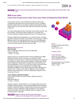

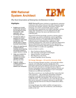


© Copyright 2026