
54B - EvoScan
Main
Index
GROUP 54B
Group
TOC
SMART WIRING
SYSTEM (SWS)
CONTENTS
GENERAL INFORMATION . . . . . . . .
54B-2
DIAGNOSTIC FUNCTION . . . . . . . . .
54B-8
COMMUNICATION METHOD . . . . . .
54B-3
ECU FUNCTIONS AND CONTROLS
IN THE SWS . . . . . . . . . . . . . . . . . . . . 54B-11
MULTI-DISTRIBUTION
INPUT/OUTPUT BY CIRCUIT . . . . . .
54B-4
CUSTOMISE FUNCTION . . . . . . . . . . 54B-25
54B-2
SMART WIRING SYSTEM (SWS)
GENERAL INFORMATION
GENERAL INFORMATION
SWS is a minimal line system which transmits
numerous signals using one wiring.
To transmit numerous signals, the ETACS*1-ECU,
column switch (incorporating inside the column-ECU) incorporate multi-distribution circuits to
carry out communication between control units.
ETACS-ECU can receive some input signals through
CAN*2 communication, improving the SWS function.
*1
M2541000100424
Main
Index
NOTE: : ETACS (Electronic Time and Alarm Control System)
Group
NOTE: *2: CAN (Controller Area Network)
TOC
For more information, refer to GROUP 54C P.54C-2.
CONSTRUCTION DIAGRAM
Column switch
ETACS-ECU
AC401291 AB
54B-3
SMART WIRING SYSTEM (SWS)
COMMUNICATION METHOD
COMMUNICATION METHOD
M2541001000527
Engine-ECU <M/T> or
Engine-CVT-ECU <CVT>
ABS-ECU*1 or
ASC-ECU*2
SWS
communication
Column switch
CAN
communication
ETACS-ECU
EPS-ECU
: Unidirectional communication
Combination meter
(incorporating meter-A/C-ECU)
: Bidirectional communication
NOTE
: 4A91
: 4G15
AC206910 AC
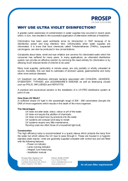
The following three types of communication systems
are connected as shown for mutual communication.
• SWS communication system in which a dedicated signal line for sending multiplex data connects ETACS-ECU and the column switch (in the
column ECU)
• CAN communication system in which twisted-pair
cables with high resistance to noise connect
ETACS-ECU, engine-ECU <M/T>,
engine-CVT-ECU <CVT>, ABS-ECU <4A9>,
ASC-ECU <4G1>, EPS-ECU, and the combination meter (in the meter-A/C-ECU)
NOTE: For information on CAN, refer to GROUP
54C P.54C-2.
Main
Index
Group
TOC
54B-4
SMART WIRING SYSTEM (SWS)
MULTI-DISTRIBUTION INPUT/OUTPUT BY CIRCUIT
MULTI-DISTRIBUTION INPUT/OUTPUT BY CIRCUIT
M2541002000649
Multi-distribution is employed by the following circuits. The relation of the input switches, sensors,
ECUs connected by multi-distribution lines, and outputs are also shown below.
Buzzer
• Lamp reminder buzzer function
• Door-ajar warning buzzer function
Circuit and Input Switch
Group
TOC
• Turn-signal operation sound function
ECUs and Switches
Connected by
Multi-Distribution
Output
Column switch
(Lighting or turn
signal lamp
switch)
• Ignition switch (IG1)
• Driver's door switch
• Hazard lamp switch
ETACS-ECU
Combination meter
• Vehicle speed signal
• Ignition switch (IG1)
Buzzer (built-in ETACS-ECU)
: SWS communication line
: CAN communication line
AC601725AB
Keyless entry
• Multi-mode keyless entry system
• Keyless entry hazard answerback function
Circuit and Input Switch
•
•
•
Respective door switches
Key reminder switch
Keyless entry transmitter
Main
Index
• Keyless entry room lamp answerback function
ECUs and Switches
Connected by
Multi-Distribution
ETACS-ECU
Output
• Electric retractable remote
controlled mirror
• Respective turn signal lamps
• Room lamp
AC401127 AB
54B-5
SMART WIRING SYSTEM (SWS)
MULTI-DISTRIBUTION INPUT/OUTPUT BY CIRCUIT
Main
Index
Power window
• Power window timer function
Circuit and Input Switch
• Ignition switch (IG1)
• Driver's door switch
• Passenger's door switch
ECUs and Switches
Connected by
Multi-Distribution
ETACS-ECU
Combination meter
• Ignition switch (IG1)
Group
TOC
Output
Power window relay
: CAN communication line
AC401129 AB
Windshield wiper and washer
• Windshield mist wiper
• Vehicle speed-dependent variable windshield
intermittent wiper
Circuit and Input Switch
• Windshield low speed wiper
• Windshield high speed wiper
• Windshield washer
ECUs and Switches
Connected by
Multi-Distribution
Output
Column switch
(Windshield
wiper and washer
switch)
• Ignition switch (IG1)
• Ignition switch (ACC)
Combination meter
• Ignition switch (IG1)
• Vehicle speed signal
ETACS-ECU
• Windshield wiper motor
• Windshield washer motor
: SWS communication line
: CAN communication line
AC401803 AB
54B-6
SMART WIRING SYSTEM (SWS)
MULTI-DISTRIBUTION INPUT/OUTPUT BY CIRCUIT
Rear wiper washer
• Rear wiper
Circuit and Input Switch
Main
Index
• Rear washer
ECUs and Switches
Connected by
Multi-Distribution
Group
TOC
Output
Column switch
(Rear wiper and
washer switch)
• Ignition switch (IG1)
• Ignition switch (ACC)
ETACS-ECU
• Rear wiper motor
• Rear washer motor
Combination meter
• Ignition switch (IG1)
Engine-CVT-ECU
• Inhibitor switch
: SWS communication line
: CAN communication line
AC207065AB
Lighting
• Headlamp, tail lamp
Circuit and Input Switch
• Fog lamp
ECUs and Switches
Connected by
Multi-Distribution
Output
Column switch
(Lighting switch)
• Ignition switch (IG1)
• Fog lamp switch
• Driver's door switch
Combination meter
• Ignition switch (IG1)
ETACS-ECU
• Illumination lamps
• Headlamp
• Tail lamps
• Fog lamps
Combination meter
• High beam indicator lamp
• Fog lamp indicator lamp
: SWS communication line
: CAN communication line
AC401132AC
54B-7
SMART WIRING SYSTEM (SWS)
MULTI-DISTRIBUTION INPUT/OUTPUT BY CIRCUIT
Flasher timer
• Turn signal lamp
Circuit and Input Switch
Main
Index
• Hazard warning lamp
ECUs and Switches
Connected by
Multi-Distribution
Group
TOC
Output
Column switch
(Turn-signal lamp
switch)
• Ignition switch (IG1)
• Hazard lamp switch
Combination meter
• Ignition switch (IG1)
ETACS-ECU
Turn signal lamp
Combination meter
• Turn signal indicator lamps
: SWS communication line
: CAN communication line
AC207067AB
54B-8
SMART WIRING SYSTEM (SWS)
DIAGNOSTIC FUNCTION
DIAGNOSTIC FUNCTION
M2541003000642
DIAGNOSIS CODE SET
For more information about diagnosis code output,
refer to the Workshop Manual.
SWS INPUT SIGNAL CHECK USING
M.U.T.-III
SWS INPUT SIGNAL CHECK AND ECU
CHECK BY USING SWS MONITOR
Group
The switch signals sent by ECUs and the operations TOC
of these ECUs can be confirmed by using the SWS
monitor and the M.U.T.-III.
When the M.U.T.-III is connected to the diagnosis
connector and any of the SWS-linked switches is
operated, the PC buzzer sounds to evaluate whether
the switch is normal or not.
INPUT SIGNALS THAT CAN BE CHECKED
Input signal
Condition for sounding buzzer
Display on
M.U.T.-III (when
SWS monitor is
used)
Ignition switch (ACC)
Turn from "LOCK" (OFF) to "ACC" position
from OFF to ON
Ignition switch (IG1)
Turn from "ACC" to "ON" position
from OFF to ON
Key reminder switch
Remove the ignition key from ignition key cylinder
(form inserted position)
from OFF to ON
Hazard lamp switch
Turn from OFF to ON
from OFF to ON
Speed signal
When the speed changes from less than 10 km/h to
more than 10 km/h
Displays the
vehicle speed
Cranking signal
While the ignition switch is in START position (while
cranking the engine)
−
Selector lever P position signal When the selector lever is shifted to the "P" position
(parking)
(Ignition switch: ON or START)
−
Selector lever R position signal When the selector lever is shifted to the "R" position
(reverse)
(Ignition switch: ON or START)
−
Buzzer triggered by
ETACS-ECU*1
ON
Fog lamp switch
Remote controlled mirror
switch (unfolding/folding
switch)
When the following conditions are satisfied
• Ignition switch: LOCK (OFF) position
• Lighting switch: ON
• Driver’s door switch: ON (Driver’s door: OPEN)
When requirements for sounding each warning buzzer OFF
are not satisfied
Door switch
Driver’s door
Passenger’s
door
When door(s) or tailgate is opened from the closed
position
from OFF to ON
A door is opened when all the doors are closed
from OFF to ON
Rear door
All door switch
Main
Index
54B-9
SMART WIRING SYSTEM (SWS)
DIAGNOSTIC FUNCTION
Input signal
Condition for sounding buzzer
Display on
M.U.T.-III (when
SWS monitor is
used)
Driver's door lock actuator
switch
Move the door lock knob or driver’s door key cylinder
from lock position to unlock position or vice versa
from ON to OFF or
from OFF to ON
Driver's door unlock actuator
switch
from OFF to ON or
from ON to OFF
Power window timer duration*1 When the power window timer is activated
Displays the
operation duration
Column
switch
Tail lamp switch When the lighting switch is turned from one position to from OFF to ON
the tail lamp position
Headlamp
switch
When the lighting switch is turned from one position to
the headlamp position
Dimmer switch When the switch is turned from the OFF to the ON
Passing switch position
Turn signal
lamp LH switch
Turn signal
lamp RH switch
Headlamp specification*1
The display alters according to the headlamp
specification ("4 BULBS" or "2 BULBS").
4 BULBS
Column
switch (wiper
switch)
When the switch is turned from OFF to ON
from OFF to ON
Windshield
intermittent
wiper volume
When the interval adjusting knob is turned from
"FAST" to "SLOW" while the ignition switch is ON.
Displays the
windshield
intermittent wiper
volume voltage
Front
When activated from the stopped condition
from OFF to ON
Windshield
mist wiper
switch
Windshield
intermittent
wiper switch
Windshield low
speed wiper
switch
Windshield
high speed
wiper switch
Windshield
washer switch
Rear wiper
switch
Rear washer
switch
Wiper
autostop
signal
Rear
Main
Index
Group
TOC
54B-10
SMART WIRING SYSTEM (SWS)
DIAGNOSTIC FUNCTION
Input signal
Condition for sounding buzzer
Display on
M.U.T.-III (when
SWS monitor is
used)
With windshield intermittent
wiper control*1
The display alters according to the presence of the
equipment ("EQUIP" or "NONE").
EQUIP
Specification switching
terminal*1
The display alters according to the transmission type
("A/T" or "M/T").
M/T or A/T
Diagnosis connector*1
Diagnosis control line: Earthed
ON
Diagnosis control line: Not earthed
OFF
NOTE: .
• − shown in the table indicates that the check item for the input of the corresponding signal is not present in
M.U.T.-III.
*1Checking
•
the input signal by the sound of the buzzer is not possible. Input signal must be checked on
the M.U.T.-III display.
•
*2:
Buzzer sound during the check is triggered by the input signal from the ignition switch. It is not to check
the presence of the power window switch acceptance permission signal.
•
*3
: Buzzer sound during the check is triggered by the input signal from the keyless entry transmitter. It is
not to check the presence of the multimode keyless entry input signal.
Main
Index
Group
TOC
SMART WIRING SYSTEM (SWS)
ECU FUNCTIONS AND CONTROLS IN THE SWS
54B-11
ECU FUNCTIONS AND CONTROLS IN THE SWS
M2541004000805
Following functions are controlled by ECUs of SWS.
Function
Control ECU
Function
description
Buzzer
Lamp reminder buzzer function
ETACS-ECU, Column switch
P.54B-12
Door-ajar warning buzzer function
ETACS-ECU
P.54B-12
Turn-signal lamp operation sound
function
ETACS-ECU, Column switch
P.54B-13
Central door
Central door locking control function
locking system Shift "P" position linked door unlock
function <CVT>
ETACS-ECU
P.54B-13
Power window Power window timer function
ETACS-ECU
P.54B-14
Keyless entry
system
Multi-mode keyless entry system
ETACS-ECU
P.54B-14
Keyless entry hazard answerback
function
ETACS-ECU
P.54B-14
Keyless entry room lamp answerback
function
ETACS-ECU
P.54B-15
Intermittent control <Vehicle
speed-dependent variable type>
ETACS-ECU, Column switch
P.54B-16
Windshield
wiper and
washer
P.54B-13
Mist wiper control
P.54B-16
Low speed wiper and high speed wiper
control
P.54B-17
Windshield wiper linked with washer
function
P.54B-18
Rear wiper and Rear wiper control
ETACS-ECU, Column switch
washer
Rear wiper linked with washer function
P.54B-19
Electric
retractable
remote
controlled
mirror
Electric retractable remote controlled
mirror timer function
P.54B-20
Flasher timer
function
Turn-signal lamp
ETACS-ECU
Automatic unfolding function
P.54B-20
P.54B-21
ETACS-ECU, Column switch
P.54B-21
Hazard lamp
P.54B-22
Turn-signal lamp indicator
P.54B-22
Headlamp
High-beam indicator
ETACS-ECU, Column switch
P.54B-22
Fog lamp
Fog lamp control
ETACS-ECU, Column switch
P.54B-22
Fog lamp indicator
P.54B-22
Main
Index
Group
TOC
54B-12
SMART WIRING SYSTEM (SWS)
ECU FUNCTIONS AND CONTROLS IN THE SWS
Function
Interior lamp
Interior lamp dimmer control function
ETACS-ECU
P.54B-23
P.54B-24
Door-ajar indicator
P.54B-24
ETACS-ECU
BUZZER
LAMP REMINDER BUZZER FUNCTION
Tail lamp, headlamp
or fog lamp
Buzzer
output
Function
description
Ignition key cylinder illumination lamp
control function
Customize function
Driver's
door switch
Control ECU
Refer to
P.54B-25.
DOOR-AJAR WARNING BUZZER
FUNCTION (THE INITIAL CONDITION:
WITH FUNCTION)
ON
ON
Ignition switch
OFF
OFF
ON (Open)
Door or (Opened) ON
tailgate
switch (Closed) OFF
OFF (Closed)
Vehicle speed
ON (Buzzer sounds)
8 km/h
0 km/h
OFF (Buzzer does
not sound)
AC208400AB
When the ignition key is removed and then the
driver's door is opened with turning ON the tail lamp,
fog lamp or head lamp, the buzzer sounds continuously to alert the driver that the lamp is still ON.
However, if the tail lamp or the headlamp is turned off
by the headlamp automatic-shutdown function, the
buzzer does not sound.
Buzzer (Sounds) ON
output
OFF
(Does not sounds)
AC101625AD
If the vehicle speed sent from the combination meter
via CAN communication exceeds 8 km/h when a
door is open for one second or more, the
ETACS-ECU makes the door ajar indicator lamp
flash 16 times and activates the buzzer (beeping 16
times) to inform the driver that a door is open.
NOTE: Availability of the door-ajar alarm function
can be selected by the customize function (Refer to
P.54B-25).
Main
Index
Group
TOC
54B-13
SMART WIRING SYSTEM (SWS)
ECU FUNCTIONS AND CONTROLS IN THE SWS
TURN-SIGNAL LAMP OPERATION SOUND FUNCTION (THE INITIAL CONDITION:
WITHOUT FUNCTION)
CENTRAL DOOR LOCKING SYSTEM
Turn signal
ON
lamp switch
CENTRAL DOOR LOCKING CONTROL
OFF
(RH)
FUNCTION
Turn signal
lamp (RH)
ON
OFF
ON
Turn signal
lamp switch
(LH)
Lock switch
ON
OFF
OFF
Unlock switch
ON
OFF
Turn signal
lamp (LH)
Hazard lamp
switch
Hazard lamp
ON
Lock relay output
OFF
ON
OFF
Unlock relay output
ON
t
ON
OFF
OFF
t
t: 0.25 second
ON
OFF
ON (Buzzer
sounds)
Buzzer
output
OFF (Buzzer
does not sound)
AC206262AB
ETACS-ECU buzzer sounds simultaneously with the
blinks of the turn-signal lamp and the hazard lamp.
NOTE: Availability of the turn-signal lamp operation
tone function can be selected by the customize function (Refer to P.54B-25).
AC101496AC
When the front doors are locked (when the lock
switch turns ON after turning OFF the unlock switch
in the driver's door lock actuator), ETACS-ECU turns
ON the lock relay output for 0.25 second, and locks
all doors (including the tailgate).
When the front doors is unlocked (when the unlock
switch turns ON after turning OFF the lock switch on
the driver's door lock actuator), ETACS-ECU turns
ON the unlock relay output for 0.25 second, and
unlocks all doors (including the tailgate).
SHIFT "P" POSITION LINKED DOOR
UNLOCK FUNCTION (THE INITIAL
CONDITION: WITH FUNCTION) <CVT>
Inhibiter switch "P"
ON
OFF
Unlock relay output
ON
OFF
T
t
t: 0.25 second
T: 0.3 second
AC208135AB
When the selector lever is shifted to "P" position
(parking) (inhibitor switch "P" is ON) with the ignition
switch turned to the ON position, the ETACS-ECU
turns on the unlock relay output for 0.25 second (0.3
second after the selector lever operation) and
unlocks all the doors (including the tailgate).
NOTE: Using a customisation function, this function
can be enabled or disabled. For more information
about the customisation function, refer to P.54B-25.
Main
Index
Group
TOC
54B-14
SMART WIRING SYSTEM (SWS)
ECU FUNCTIONS AND CONTROLS IN THE SWS
POWER WINDOW
POWER WINDOW TIMER FUNCTION
Ignition switch (IG1)
KEYLESS ENTRY HAZARD
ANSWERBACK FUNCTION (INITIAL
SETTING: LOCK, FLASH ONCE,
UNLOCK, FLASH TWICE)
ON
LOCK
OFF
Keyless entry
transmitter
(Open)ON
Driver's door and
passenger's
(Close)OFF
switch
OFF
Lock relay output
UNLOCK
ON
OFF
Power window relay
ON
Unlock relay output
OFF
t
t:30 seconds
ON
OFF
t
AC309963AB
When the power window relay is turned ON with the
ignition switch ON, the power window relay is kept
ON for 30 seconds even after the ignition switch is
turned OFF, enabling the door window to be opened
and closed with the power window switch.
If the driver's or the front passenger door is opened
during timer operation, the power window relay is
turned OFF at the same time.
KEYLESS ENTRY SYSTEM
MULTI-MODE KEYLESS ENTRY SYSTEM
The door mirrors can be operated by the keyless
entry transmitter operation.
For the operation, refer to Group 42 − Body − Keyless entry system P.42-13.
Hazard lamp
Illuminate
Extinguish
AC209072AG
The hazard answer back function that allows checking the lock/unlock state of the door easily even in
the daytime is installed. When the lock signal from
the keyless entry transmitter is received into
ETACS-ECU, all doors (including the tailgate) are
LOCK, and the turn signal lamp blinks once. When
the unlock signal is received, all doors (including the
tailgate) are UNLOCK, and the turn-signal lamp
blinks twice.
NOTE: The answer back blink time can be adjusted
by the customise function (Refer to P.54B-25).
Main
Index
Group
TOC
54B-15
SMART WIRING SYSTEM (SWS)
ECU FUNCTIONS AND CONTROLS IN THE SWS
KEYLESS ENTRY ROOM LAMP ANSWERBACK FUNCTION (INITIAL SETTING: LOCK
FLASH ONCE, UNLOCK ILLUMINATES FOR 15 SECONDS)
Group
TOC
ON
Unlock relay output
OFF
ON
Lock relay output
OFF
ON
Door lock switch output
OFF
ON
Door unlock switch output
OFF
Illuminate
Hazard lamp
Extinguish
Illuminate
Interior lamp
Extinguish
a: 0.6 second
b: 1.2 seconds
c: 15 seconds
When the ETACS-ECU receives the lock signal from
the keyless entry transmitter, all doors (including tailgate) is locked and the interior lamp flashes once in
synchronization with the hazard lamp operation.
When the ETACS-ECU receives the unlock signal,
all doors (including tailgate) is unlocked. The interior
lamp fades in, keeps on, and fades out in 15 seconds
after the door unlock relay is operated. (15 seconds
including fading period)
Main
Index
a
b
c
AC314090AB
NOTE: The answerback blink time can be adjusted
by the customize function. (Refer to P.54B-25).
54B-16
SMART WIRING SYSTEM (SWS)
ECU FUNCTIONS AND CONTROLS IN THE SWS
WINDSHIELD WIPER AND WASHER
INTERMITTENT CONTROL <VEHICLE
SPEED-DEPENDENT VARIABLE TYPE>
(THE INITIAL CONDITION: WITH FUNCTION)
1.
Windshield
wiper autostop signal
Windshield
wiper relay
Change in intermittent time by variable
intermittent wiper control volume
(when vehicles is stationary)
Main
Index
2.
ON
Group
TOC
OFF
ON
T1
T1
T1
OFF
32
AC101493AF
Intermittent time
T1 (seconds)
0
FAST
SLOW
Variable intermittent wiper
control switch position
AC314042AB
Change in intermittent time according
to vehicle speed
When at SLOW position
32
25
22
Intermittent
time T1
(seconds)
19
When ETACS-ECU receives the windshield intermittent wiper switch ON signal from the column
switch while the ignition switch is in the ACC or
ON position, it turns the windshield wiper relay
ON to operate the windshield wiper at low speed.
3. When the windshield wiper comes to the stop
position, the windshield wiper auto stop signal
turns OFF. Then the windshield wiper relay will
turn OFF, and the windshield wiper stops operating.
4. When the intermittent time T1 has elapsed after
the windshield wiper relay was turned OFF,
ETACS-ECU turns ON the windshield wiper relay
again and repeats the above procedure.
MIST WIPER CONTROL
14
When at FAST position
4.6
2.0
1.6
0
Windshield mist
wiper switch
Windshield wiper
auto-stop signal
14
30 40
60
100
Vehicle speed (km/h)
AC314043AB
The ETACS-ECU calculates the windshield intermittent wiper interval T1 from the windshield intermittent wiper volume and vehicle speed signal
(sent from the combination meter to the
ETACS-ECU via CAN communication).
NOTE: The vehicle speed-sensitive function can be
adjusted by the customise function (Refer to
P.54B-25).
Windshield wiper
relay
Windshield wiper
speed switching
relay
ON
OFF
ON
OFF
ON
OFF
ON (HIGH)
OFF (LOW)
AC207004 AB
When the windshield mist wiper switch of the column
switch is turned ON with the ignition switch in the
ACC or ON position, ETACS-ECU turns ON the
windshield wiper drive signal. At the same time, the
wiper speed switch relay turns to ON (HIGH). When
the windshield mist wiper switch is ON, the windshield wiper operates at the high speed.
54B-17
SMART WIRING SYSTEM (SWS)
ECU FUNCTIONS AND CONTROLS IN THE SWS
LOW SPEED WIPER AND HIGH SPEED WIPER CONTROL
Windshield low speed
wiper switch
ON
OFF
OFF
Windshield wiper auto-stop
signal
OFF
Windshield wiper speed
switching relay
Group
TOC
ON
Windshield high speed
wiper switch
Windshield wiper
drive signal
Main
Index
ON
ON
OFF
(HI) ON
(LO) OFF
Low speed operations
When the windshield low speed wiper switch of the
column switch is turned ON while the ignition switch
is ACC or ON, the column switch turns ON the windshield wiper drive signal. Also, the wiper speed
switching relay turns to OFF (LO), and the windshield
wiper operates at the low speed.
High speed operations
AC005437AB
When the windshield high speed wiper switch is
turned ON, the windshield wiper drive signal turns
ON. Also, the wiper speed switching relay turns ON
(HI), and the windshield wiper operates at the high
speed.
54B-18
SMART WIRING SYSTEM (SWS)
ECU FUNCTIONS AND CONTROLS IN THE SWS
WINDSHIELD WIPER LINKED WITH WASHER FUNCTION (INITIAL CONDITION: WITH
THE WINDSHIELD WIPER LINKED WITH WASHER FUNCTION)
Main
Index
ON
Windshield washer switch
Windshield washer relay
Group
TOC
OFF
ON
t
t
OFF
ON
Windshield wiper
auto stop signal
OFF
ON
Windshield wiper relay
OFF
T
T
Wiper switch in intermittent
operation position
Wiper switch in
off position
AC309988AC
t: 0.2 or 0.3 second
T: Intermittent wiper intermittent time
Wiper
switch
OFF position
Intermittent operation position
Low-speed or
high-speed
operation
position
Washer
0.3
0.3 to 0.5 0.5
0.2
switch ON second or second
second or seconds
time (t)
less
more
or less
0.2 to 0.4 0.4 to 0.6 0.6
−
second
second
second or
more
T
1 second
0 second
2 seconds 3 seconds 0 second
When the windshield washer switch in the column
switch is turned ON with the ignition switch in the
ACC or ON position, the ETACS-ECU turns ON the
windshield washer relay.
When the windshield washer switch is kept ON for
0.3 seconds, the windshield wiper drive signal (the
wiper drive signal output time varies depending on
the conditions. For details, refer to the tables) is
turned ON, and the windshield wiper is operated at
high speed. Three seconds after turning OFF the
windshield washer switch, the windshield wiper turns
OFF.
Even when the windshield washer switch is turned
ON while the windshield wiper is operating intermittently, the intermittent action is kept after the linked
operation is finished.
2 seconds 3 seconds 3 seconds
If the ignition switch is set to the ACC position while
the windshield washer switch is being turned ON, the
windshield washer relay becomes ON, but the windshield wiper does not start the linked operation.
When the windshield washer switch is turned OFF
and then ON again, the windshield wiper makes the
linked operation.
NOTE: .
• Using a customisation function, the driver can
enable or disable the windshield wiper linked with
washer function. For more information about the
customisation feature, refer to P.54B-25.
• When the windshield wiper linked with washer
function is disabled by the customisation feature,
the windshield wiper does not operate in synchronization with the windshield washer. However,
the windshield washer can be activated. It is useful to melt down the ices of the frozen windshield.
54B-19
SMART WIRING SYSTEM (SWS)
ECU FUNCTIONS AND CONTROLS IN THE SWS
Main
REAR WIPER AND WASHER
REAR WIPER CONTROL [THE INITIAL CONDITION: 8 SECONDS (WITHOUT SUCCES- Index
SIVE OPERATIONS)]
Group
ON
Rear wiper switch
TOC
OFF
ON
Inhibitor switch "R" position
OFF
T2
Rear wiper drive signal
t
T3
T2
T3
T3
ON
OFF
T1
T4
T2
T4
T1
T4
T2
T4
T2
T4
AC207474AB
t: 1.0 second
T1: 3.0 seconds
T2: 7.4 seconds
T3: 8.0 seconds
T4: 0.6 second
1. When the rear wiper switch on the column switch
is turned ON with the ignition switch at the ACC
or ON position, ETACS-ECU turns ON the rear
wiper drive signal for 3 seconds (approximately 2
operations) and performs the intermittent action
at 8-second intervals.
When the selector lever is moved to R position during the rear wiper operation, the inhibitor switch R
position turns ON one second after that,
ETACS-ECU sends the rear wiper drive signal for
3 seconds (approximately 2 operations), and
operates the intermittent action in 8 seconds
interval. <CVT>
2. By the special operation of the rear wiper switch
on the column switch (successive 2-time operations), the rear wiper operates continuously
regardless of the set intermittent time.
NOTE: The rear wiper intermittent time can be
adjusted or cancelled for continuous operation by the
customise function (Refer to P.54B-25).
54B-20
SMART WIRING SYSTEM (SWS)
ECU FUNCTIONS AND CONTROLS IN THE SWS
REAR WIPER LINKED WITH WASHER FUNCTION (THE INITIAL CONDITION: WITH
FUNCTION)
ON
Group
TOC
Rear washer switch
OFF
ON
Rear washer relay
OFF
T3
T2
Rear wiper relay
t
t
ON
OFF
t
T1
T1
T1
T4
t : 0.3 second
T1 : 3 seconds
T2 : 7.4 seconds
T3 : 8 seconds
T4 : 0.6 second
Rear wiper switch
in off position
T4
Rear wiper switch in on position
• When the rear washer switch on the column
switch is turned ON with the ignition switch ACC
or ON, ETACS-ECU turns ON the rear washer
relay. When the rear washer switch signal from
the column switch remains ON for 0.3 seconds or
more, ETACS-ECU turns ON the rear wiper relay
to operate the rear wiper continuously. When the
rear washer switch is turned OFF, the
ETACS-ECU turns OFF the rear wiper relay 3
seconds later. Then the rear wiper stops at the
auto stop position.
AC207003AB
• Even turning ON the rear washer switch during
rear wiper operation causes the rear wiper relay
to switch the operation to continuous operation,
and then the rear wiper resumes intermittent
operation at intervals of eight seconds, 7.4 seconds after the completion of the continuous operation.
NOTE: Using a customisation function, a driver can
enable or disable the rear wiper linked with washer
function. For more information about the customisation feature, refer to P.54B-25.
ELECTRIC RETRACTABLE REMOTE CONTROLLED MIRROR
ELECTRIC RETRACTABLE REMOTE CONTROLLED MIRROR TIMER FUNCTION
Ignition switch (ACC)
ON
T1
T1
OFF
Remote controlled mirror switch
(folding/unfolding switch)
Door mirror unfold relay
ON
OFF
ON
T2
T2
T2
OFF
t
t
Door mirror fold relay
Main
Index
ON
T2
T2
t
T2
OFF
t: 0.1 second
T1: 30 seconds
T2: 16 seconds
When the unfolding/folding switch on the fold switch
remote controlled mirror switch is turned ON with the
ignition switch at the ACC or ON position, the door
mirror unfold relay or fold relay is turned on for 16
seconds to unfold or fold the door mirrors. Even after
the ignition switch is turned OFF, the door mirrors
can operate for 30 seconds.
AC309810 AC
If the unfolding/folding switch on the remote controlled mirror switch is turned ON while one of the door
mirror unfold relay or door mirror fold relay is in operation, the other relay for the opposite motion is
turned ON after 0.1 second.
SMART WIRING SYSTEM (SWS)
ECU FUNCTIONS AND CONTROLS IN THE SWS
54B-21
Main
Index
NOTE: Whether the door mirrors are at the unfolding
or folding position is determined according to the
memory of the door mirror fold relay operated previously. For this reason, if the door mirrors are manually retracted, they may not move when the
unfolding/folding switch on the fold switch remote
controlled mirror switch is pressed next time.
Group
TOC
AUTOMATIC UNFOLDING FUNCTION
1.
Vehicle speed
Ignition switch
30 km/h
0 km/h
ON
OFF
Remote controlled mirror switch
(folding/unfolding switch)
Door mirror unfold relay
ON
OFF
ON
T
OFF
Door mirror fold relay
ON
T
OFF
Door mirror position
Unfolding
Folding
AC207002AB
T : 16 seconds
Vehicle speed-dependent automatic unfolding function
When the vehicle speed reaches 30 km/h, with the
ignition switch ON and the mirrors retracted,
ETACS-ECU turns on the retraction mirror relay
(unfolding) for 16 seconds to return the door mirrors. However, the door mirrors do not return to
their normal positions automatically if the ignition
switch is turned from OFF to ON, and then the
unfolding/folding switch on the remote controlled
mirror switch is operated.
NOTE: Whether the door mirrors are at the unfolding
or folding position is determined according to the
memory of the retraction mirror relay operated previously. For this reason, if the mirrors are manually
retracted, they may not move when the unfolding/folding switch is pressed next time.
FLASHER TIMER FUNCTION
TURN-SIGNAL LAMP (INITIAL SETTING:
TURN SIGNAL LAMP CAN BE OPERATED
WHEN THE IGNITION SWITCH IS IN THE
ON POSITION)
Ignition
switch (IG)
ON
OFF
Turn-signal lamp ON
switch RH
OFF
Turn-signal lamp ON
switch LH
OFF
Turn-signal lamp ON
output RH
OFF
Turn-signal lamp ON
output LH
OFF
AC101508AC
When the turn-signal lamp switch is ON (LH or RH)
with the ignition switch is ON, the turn-signal lamp
output (flash signal) is turned ON.
If the lamp bulb of the front or rear turn-signal lamp
has burned out, the flashing speed becomes faster to
alert the driver that the lamp bulb has burned out.
NOTE: Using a customisation function, this function
becomes available even when the ignition switch is
in the ACC position. For more information about the
customisation feature, refer to P.54B-25.
54B-22
SMART WIRING SYSTEM (SWS)
ECU FUNCTIONS AND CONTROLS IN THE SWS
HAZARD LAMP
Hazard lamp
switch
Turn signal
lamp output
RH
Turn signal
lamp output
LH
TURN-SIGNAL LAMP INDICATOR
The ETACS-ECU sends the turn signal lamp indicator ON signal to the combination meter through CAN
communication in synchronization with the turn signal lamp operation. The combination meter receives Group
TOC
the transmitted signal and turns ON or OFF the
turn-signal lamp indicator.
ON
OFF
ON
OFF
ON
HEADLAMP
HIGH-BEAM INDICATOR
OFF
AC101509AC
When the hazard lamp switch input signal turning
from OFF to ON is detected, the flashing states turns
over by the signal (When the hazard lamp is not
blinking, it blinks. If it is blinking, it turns off).
NOTE: .
1. The push-return switch is adopted for the hazard
lamp switch.
2. Even if the lamp bulb has burned out, the flashing
speed of the hazard lamp is not changed.
The ETACS-ECU sends the high beam indicator ON
signal to the combination meter through CAN communication in synchronization with the high beam
headlamp operation. The combination meter
receives the transmitted signal and turns ON or OFF
the high beam indicator.
FOG LAMP
FOG LAMP CONTROL
Headlamp
Lighting switch
Tail lamp
OFF
Fog lamp switch
ON
OFF
(Illuminated) ON
Headlamp
Tail lamp
Fog lamp output
Main
Index
(Extinguished) OFF
(Illuminated) ON
(Extinguished) OFF
(Illuminated) ON
(Extinguished) OFF
AC401793 AB
When the fog lamp switch is turned to ON with the
tail lamp or the headlamp lit (the tail lamp switch or
the headlamp switch is ON), the fog lamp relay turns
ON, and the fog lamps turn on.
If the tail lamp or the headlamp is turned off with the
lighting switch OFF while the fog lamps lit, the fog
lamps turn off the same time to prevent unattended
operation.
FOG LAMP INDICATOR
The ETACS-ECU sends the fog lamp indicator ON
signal to the combination meter through CAN communication in synchronization with the fog lamp
operation. The combination meter receives the transmitted signal and turns ON or OFF the fog lamp indicator.
SMART WIRING SYSTEM (SWS)
ECU FUNCTIONS AND CONTROLS IN THE SWS
54B-23
INTERIOR LAMP
INTERIOR LAMP DIMMER CONTROL FUNCTION (THE INITIAL CONDITION: 15 SECONDS)
Group
TOC
ON
Ignition switch
ACC
OFF
Key removed
Door switch
(Any one open) ON
Driver's door
lock actuator switch
(lock switch)
(All closed) OFF
(Lock) ON
(Unlock) OFF
100 %
60 %
Interior lamp brightness
0%
15 seconds
15 seconds
AC310305AC
When the interior lamp switch is on the door position,
ETACS-ECU controls the interior lamp lamps as follows.
1. When the ignition switch is OFF:
By opening any door or tailgate, the lamp turns ON
(100%), and dims (60%) when the door or tailgate is closed, then and turns off after 15 seconds.
However, when the ignition switch is turned ON or
the door lock is operated, the lamps turn off at
that time.
2. When the ignition switch is ON:
By opening any door or tailgate, the lamp (100%)
turns ON and OFF when the door or tail gate is
closed.
Main
Index
3. When all doors and the tailgate are closed, and
the ignition key is removed:
By removing the ignition key with all doors and the
tailgate closed, the lamp turns ON 60%, and
turns off after 15 seconds.
By inserting the ignition key again or operating the
door lock with the lamp lit, the lamps turns off.
NOTE: For the vehicles with the keyless entry system, the delayed lamp-off time and the operation
times of the keyless entry interior lamp answer back
can be changed by the customise function (Refer to
P.54B-25).
54B-24
SMART WIRING SYSTEM (SWS)
ECU FUNCTIONS AND CONTROLS IN THE SWS
IGNITION KEY CYLINDER ILLUMINATION LAMP CONTROL FUNCTION
Ignition switch (IG)
Main
Index
ON
OFF
Group
TOC
(Key removed) ON
Key reminder switch
(Key inserted) OFF
Driver's seat door switch
(Opened) ON
(Closed) OFF
Ignition key cylinder
illumination lamp
(Illuminated) ON
(Extinguished) OFF
t
t
t
t
t
t
t
t: 30 seconds
AC314095 AB
The ETACS-ECU controls the ignition key cylinder
illumination lamp and foot lamp as described below.
1. The ignition key cylinder illumination lamp and for
30 seconds when the driver's door is
opened/closed with the ignition switch OFF.
2. Also when the ignition key is removed from the
ignition key cylinder, the lamp illuminates for 30
seconds.
3. When the ignition key cylinder illumination lamp
is operating with the doors closed, it goes out if
the ignition switch is turned ON.
DOOR-AJAR INDICATOR
The ETACS-ECU sends the open/close status of
each door to the combination meter through CAN
communication. The combination meter receives the
transmitted signal and turns ON and OFF the
door-ajar indicator. The door-ajar indicator flashes
when the door-ajar warning function is activated
while the door-ajar indicator is ON (For more information about the door-ajar warning function, refer to
).
SMART WIRING SYSTEM (SWS)
CUSTOMISE FUNCTION
54B-25
CUSTOMISE FUNCTION
M2541006000243
Main
Index
Using M.U.T.-III adjusts the following function. The
• Door-ajar warning function
Driving with any door, including a tailgate, not propprogrammed information is held even when the batGroup
tery is disconnected.
erly closed sounds the buzzer to let the driver
TOC
know the door-ajar state.
• Vehicle speed-dependent wiper function
With the windshield wiper switch in the intermittent
• Rear wiper intermittent duration
When the rear wiper switch is turned ON, the rear
position, the intermittent duration changes
wiper operates in the intermittent action. When
depending on the intermittent adjusting knob
the rear wiper switch is turned from OFF to ON
position and the vehicle speed.
two cycles, the rear wiper makes continuous
• The selector "P" position-linked central door
operation regardless of the intermittent operation
unlocking function <CVT>
duration setting.
When the selector lever is shifted to the "P" position,
• Wiper linked with washer function
all the doors unlock.
• Turn-signal lamp operation sound function
When this function is active, the windshield wiper
Synchronized with the hazard lamp and the turn sigoperates if the washer switch is turned ON.
nal lamp, the buzzer sounds.
• Hazard answer back function of the keyless entry
system
• Dimmer interior lamp control duration
When the door is closed with the ignition switch
When lock/unlock is operated with the keyless entry
LOCK (OFF), the interior lamp is turned OFF
transmitter, the horn sounds so that the driver can
automatically in the specified time.
recognize the lock/unlock status of the vehicle
even if the driver is away from it.
• Timer lock time after executing the keyless entry
• Initialising all functions (Returning to the initial
unlock
condition)
If any door including a tailgate is not opened after
All adjusting functions are returned to the settings at
being unlocked with the keyless transmitter,
the time of factory shipment.
doors are locked automatically within the specified time.
Item Items shown Item
Adjustment items
Adjusting contents
No.
on M.U.T.-III
shown on M.U.T.-III
screen
screen
4
9
14
15
SPEED SEN
WIP
Vehicle
speed-dependent
wiper function
KEYLESS(HA Hazard answer
ZD)
back function of
the keyless entry
system
W.FUNCTION
With function (Initial setting)
W/O FUNCTION
Without function
LOCK/UNLOCK
With function for lock/unlock (the initial
condition)
LOCKED
With function only for lock
UNLOCKED
Without function only for unlock
W/O FUNCTION
Without function
P UNLOCK
ACT.
Door unlock
function linked
with "P" position
shift for centre
door lock system
W.FUNCTION
With function
W/O FUNCTION
Without function (the initial condition)
T/SIG.BUZZE
R
Turn-signal lamp
operation sound
function
W.FUNCTION
With function
W/O FUNCTION
Without function (the initial condition)
54B-26
SMART WIRING SYSTEM (SWS)
CUSTOMISE FUNCTION
Item
No.
Items shown
on M.U.T.-III
screen
Item
Adjustment items
shown on M.U.T.-III
screen
Adjusting contents
16
RM LMP TN
OFF
Dimmer interior
lamp control
duration
60s
60 seconds
30s
30 seconds
15s
15 seconds (the initial condition)
7.5s
7.5 seconds
W/O FUNCTION
0 second (no delay action)
24
26
28
37
38
39
KEYLES
LOCK T
Timer lock time
30s
after executing the 60s
keyless entry
120s
unlock
180s
30 seconds (the initial condition)
1 minute
2 minutes
3 minutes
DOOR WARN Door-ajar warning W.FUNCTION
BUZ
function
W/O FUNCTION
With function (Initial setting)
R.INT WIPER
T
8s
8 seconds: Without continuous
operation (Initial setting)
4s(W SUCSSON)
4 seconds: With continuous operation
8s(W SUCSSON)
8 seconds: With continuous operation
16s(W SUCSSON)
16 seconds: With continuous operation
CONTIN ACTION
Continuous operation (without the
intermittence)
Rear wiper
intermittent
duration
Without function
WIP SYCR
WASH
Wiper linked with
washer function
W.FUNCTION
With function (Initial setting)
W/O FUNCTION
Without function
KEYLES
HAZARD
Customise
function for
changing the
number of the
keyless hazard
warning lamp
answerback
flashing
LOCK1,UNLOCK2
LOCK: Flash once, UNLOCK: Flash
twice (Initial setting)
Whether the lamps flash or not is
determined by the keyless hazard
warning lamp answerback
customisation function.
LOCK2,UNLOCK1
LOCK: Flash twice, UNLOCK: Flash
once
Whether the lamps flash or not is
determined by the keyless hazard
warning lamp answerback
customisation function.
Turn signal lamp
operation
condition
adjustment
function
IG-ON
Turn signal lamp can be operated when
the ignition switch is turned ON (Initial
setting).
IG-ACC
Turn signal lamp can be operated when
the ignition switch 1 is in ACC or ON
position.
TURN-SIGNA
L
Main
Index
Group
TOC


© Copyright 2026