
Vehicle
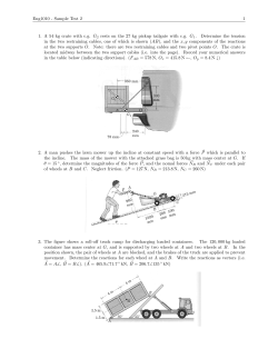
July 6, 1937.
0
2,085,944
C. L. BEST
VEHICLE
Filed Marchv 6, 1954
‘ 4 Sheets-Sheet l
IJI
IN VEN TOR.
(lire/1:9 _L. ' Besi
BY
. 7’
ATTORN
-
July 6, 1937-.
C. .L. BEST
2,085,944
VEHICLE
Filed March 6, 1934
4 Sheets-Sheet 2
NM
[N VEN TOR.
Clarence L. Ben‘
“M %f;%
A TTORNEY.
July 6, 193 7.
2,085.944
c; L.’ BEST
VEHICLE
Filed March 6, 1934
4 Sheets-Sheet 3
\
k
3
l‘dv3?u
m3n33;Li3mi?‘\“wguv5.
6N64
BY
m
7/m
L a
mfa”.
%
w
M
1
eR
I Juiy 6, 1937'.
2,085,944
c. L. BEST- -
VEHICLE‘
Filed March 6, 1934
1%
4 Sheets-Sheet 4
$5
Q:
at
'
'
C‘laren'c'e 1.. Bear‘
BWZW?
ATTORéY.
Patented July 6, 1937
_ 2,085,944
‘PATENT OFFICE
UNITED STATES
2,085,944
VEHICLE
Clarence L. Best, Mission San Jose, -Calif., as
signor to Caterpillar Tractor 00., San Leandro,
Calif., a corporation of California
Application March 6, 1934, Serial No. 714,353
5 Claims. (01. 37-178)
The present invention relates to vehicles, and a track-type tractor, to which a rearwardly ex
more particularly to the provision of a tractor
implement combination in which the implement
tending implement frame is attached, the rear
support for the implement frame being con
structed to avoid the necessity of a steering con
is connected and supported for steering as a unit
5 with the tractor or draft vehicle.
It is an object of the invention to provide a
machine of improved construction having a
trol therefor, and to permit short turning of the
tractor-implement combination. A machine of
this character is of particular applicability in road
working apparatus where the implement- frame
ground-engaging implement which is mounted
rearwardly of the draft vehicle to provide a pull
supports a ground working tool such as a grader 1
type machine, and which has ground-engaging
blade.
means providing for’steering of the implement as v
a unit with the draft vehicle.
Another object of the‘ invention is the provision
of an improved type of road machine having as a
15
draft vehicle a tractor of conventional construc
tion, and also havinga scraper blade frame con
-
.
'
The tractor comprises body l0 (Figs. 1 and 2)
which is supported upon similar opposite track
mechanisms II by means including transverse
pivot shaft I! mounted in body l0, and having
spaced pivotal connections l3, l4 with each track 15
frame It and with diagonal braces l'l therefor.
nected to the rear of said tractor to provide a
Side seat 2| is provided on body l0 ; and forwardly
pull-type road machine.
Another object of the invention is to provide a
20 road machine, of the character. described, in
which the implement frame is connected for steer
thereof,
a plurality of tractor ‘controls , are‘
mounted, including main clutch vlever 22, gear
shift lever 23, and steering clutch levers 24. In
vertical oscillation with respect to the tractor;
the implement frame having a ground support
25 independent of the tractor.
Another object of the invention is to provide
an improved tractor-implement combination, of
the character described, in which the implement
front of seat 2| at the side of the tractor, brake
pedals 26 are provided for operating the brakes
associated with the usual track steering clutches
controlled by levers 24 in the usual manner.
Implement frame 3| (Figs. 1 and 2) is provided
at the rear of the tractor, and has its front end
pivotally supported thereon, while its rear end is
provided with a caster wheel support. Frame 3|
frame has one end supported on the tractor and
30 the other end supported by a caster wheel.
includes opposite side members 32, 33 pivotally
supported at their front ends by means‘ of brack
ing as a unit with the tractor and has relative
Another object of the invention is to provide an
ets 34 on the respective ends of shaft l2, and
converging at their rear ends to bracket 36.
Bracket 36 has vertically apertured boss 31 re
ceiving post 38 of caster wheel 39. latch means
are .provided for normally preventing rotation of
caster wheel 39 with respect to frame 3|, com
improved implement frame construction having
improved ground-engaging means adapting the
implement frame for turning as a unit with the
35 draft vehicle therefor.
'
Other objects will appear as the description
progresses.
prising spring-pressed bolt 4| slidably mounted in
'
guide 42 on frame 3| and having an end normally
disposed in slot 43 of collar 44 non-rotatably se
cured on post 38. Latch operating cord 46 ex 40
tends forwardly from the front end of, bolt 4 I, and
is suitably secured to seat 2| so as to be accessible
' Description of ?gures
40
Figs. 1 and 2 illustrate one form of the inven
tion.
.
'
-
Fig. 1 is a right side elevation.
Fig. 2 is a plan view.
Figs. 3 through 5 illustrate a second form of
45 the invention.
Fig. 3 is a right side elevation.
Fig. 4 is a plan view. v
V
implement.
to the operator.
Thus, the implement frame is movably mounted
at its front end on the tractor and is provided
with a releasably locked caster wheel support at
its rear end.
Fig. 5 is a fragmentary side elevation, similar
to Fig. 3, but illustrating a different type of
50
.
‘
Description of mechanism
The vehicle or tractor-implement combination
disclosed in Figs. 1 and 2 comprises generally
55 a tractor of conventional construction, preferably
-
.
The implement supported from frame 3| is,
preferably, a conventional grader or‘ mainte
nance blade 5| adjustably mounted by means of
a tool carrying’ frame comprising conventional
circle 52 in the usual type of circle-carrying frame
53. Telescopic lift means are provided for sup
porting'the blade and circle assembly for verti
cal adJustment; telescopic adjustment thereof
2
2,085,944
being accomplished by power control means op
erable from seat 2|. As each lift means is simi
lar, only one is described in detail. The tele
scopic lift means includes cylinder 56, and piston
51 pivotally connected at 58 to circle-carrying
frame 53. Cylinder 56 has transversely aligned
pivotal connections 59 (Fig. 2) with collar or ring
6|, having longitudinally aligned pivotal connec
tions 62 with transverse frame angles 63 suitably
10 mounted on side members 32, 33.
By virtue of
pivotal connections 59, 62, the lift means is uni
versally supported on the frame of the machine.
To'accomplish adjustment of the lift means,
. ?exible pipe connections 64 communicate with
15 cylinder 56 at the opposite ends thereof, and ex
tend forwardly to valve 66, having control lever
61, and having a suitable connection with pres-
I 08 are in axial alignment with pivot shaft I2
(Fig. 2) which connects trackframes I6 and body
I0 as described previously. Rotation of shafts
I08 (Figs. 3 and 4) serves to oscillate arms IN, to
raise or lower the front end of implement frame
IOI. Within each housing I09 (Fig. 3), worm
wheel III is secured on shaft I08 and is engaged
by worm II2 on shaft II3. Shaft II3 extends
without housing I09 and is, universally connected
to telescopic shaft “4 which is universally con 10
nected at its upper end to shaft H6 in housing
III on body I0.
Bevel gear connection H8 is
provided within housing Ill to connect shaft
II6 to transverse telescopic shaft II9 extending
inwardly and connected by bevel gear connection
I2I in housing I22 to vertical shaft I23. ‘Hand
’ Wheel I24 is provided at the upper end of shaft
sure tank 68. By adjusting control lever 61, cyl
inder 56 and piston 51 can be adjusted telescopi
I23 to operate respective shafts I08 and‘arms I01.
Thus, by turning of the hand wheel I24, shafts
20 cally to raise or lower the blade, or can be main
I08 and arms I0'I can be moved to raise or lower
the front end of the frame IOI. Worms H2 and
worm wheels III are irreversible; therefore, the
adjustment of the front end of the frame is main
tained for any adjusted position.
tained ‘in any adjusted position. To prevent
transverse movement of the blade 5| with respect.
to frame 3|, transverse lock link ‘II is ‘provided,
having a pivotal connection at its lower end with
25 frame 53, and at its upper end with frame 3|.
Side members I02, I03 (Figs. 3 and 4) converge 25
A draft connection is provided for the blade or
rearwardly; and at their rear ends are connected
tool carrying frame 52, 53 to the drawbar of the
tractor and independent of the implement main
frame 3|. At its front end (Fig. 1), frame 53 has
30 downwardly extending bracket ‘I2 secured‘ there
to and which is connected by a suitable draft link
and pin to drawbar ‘I3 of the tractor.
by bracket I26 having vertically apertured boss
I2'I. Hollow post I28 (Fig. 3) of caster wheel
A scari?er is mounted at the ‘rear end of the
tractor in front of implement or blade 5I.. The
35 scari?er comprises block 8| having a plurality of
transversely spaced scari?er teeth 82 detach
ably mounted thereon. Block 8| also has oppo
site side draft connections 83 extending for
wardly, and pivotally connected to body I0 at 84.
40 Adjacent block 8 I , spaced lift bars 86 are pivotally
connected at 81 to draft connections 83. Lift bars
86 extend upwardly and are connected together
at their upper ends by cross rod '88; cross rod
88 having lift nut 89 threaded onto lift screw 9|,
45 suitably mounted on body I0 and having operat
ing hand wheel 92 immediately to the rear of
seat 2 I. Turning of hand wheel 92 provides
. means for adjustment of scari?er teeth 82 rela
tive to the ground.
While particular forms of implements are
shown, both on the implement. frame and on the
tractor, inasmuch as the implement frame con
'struction and its mounting are particularly
adapted'for road apparatus, any other suitable
55 implements can be employed, depending on the
type of ,work to be done, without departing from
the principle of the implement frame construc
tion and attachment.
In the modification shown in Figs. 3 and 4, the
60
tractor is similarto that described above, and
corresponding parts havecorresponding refer
ence numerals. The implement frame is ad
justably supported at its front end on the trac
tor, and at its rear end on a caster wheel to
accomplish steering of the tractor and the frame
as a unit.
Vertical adjustment of the imple
ment frame is designed to accomplish vertical
adjustment of the implement.
Frame IOI (Figs. 3 and 4) includes spaced side
70
members I02, I03, having downwardly extending
brackets I04 welded to the front ends ‘thereof.
Brackets I04 are pivotally connected by pins I06
to the rear ends of arms I0'I, which are secured
.for rotation with shafts I08 journaled in re
75 spective housings I69 on track frames I6. Shafts
I 29 extends upwardly within boss‘ I 21 for both
sliding and pivotal movement with respect there 30
to. Spring-pressed latch pin I3I has an end nor
mally engaged within vertical ,groove I32 in post
I28 to maintain caster wheel I29 aligned for lon
g'itudinaltravel of the vehicle. Cord I33‘ pro
' vides means for operating latch pin I3I .
Telescopic lift means are provided between
frame IM and caster wheel I29 to provide for ver
tical adjustment of the rear end of frame IOI.
Screw member I36 (Fig. 3) has a lower cylin
drically shaped end portion I36’ journaled with
in hollow post I28, and is held against endwise
movement with respect thereto by end ?ange I3‘I
contacting post I28. Square shaft I38, integral
with sleeve extension I39 of bracket I26, ex
tends downwardly from the top thereof and has 45
telescopic engagement with a, complementary
deep recess in the top of screw member I36 to pre
vent rotation of the screw member-while permit
ting relative endwise movement.
Screw mem
ber‘I36 has threaded engagement with nut mem
ber I4I mounted for rotation, and held against
50’
endwise movement within housing portion I42 of
bracket I26. Nut member I4I has integral
worm wheel I43 (Figs. 3 and 4) which is engaged'
by worm I44 (Fig. 4) on shaft I46 journaled in 55
housing portion I42. Shaft I46 (Figs. 3 and'4)
has universal connection I4'I with telescopic shaft
I48 having universal connection I49 at its front
end with shaft I5I. Shaft I5I is journaled in
bracket I52 and has hand wheel I53‘ secured 60
thereon adjacent seat 2|. By operating hand
wheel I53, nut member I4I can be rotated in
either direction on screw member I36 to effect
endwisev displacement of the screw member so
as to raise or lower the‘ rear end of- frame IOI. 65
Thus, both ends of frame IOI are adjustable
vertically to raise or lower frame IOI and corre-'
spondingly adjust the implement supported
thereon.
The implement which is mounted on frame I 0 I, 70
comprises a combined blade and scari?er which is'adjustable to operate as either a blade or a
scari?er, as determined from control means lo
cated adjacent operator’s seat 2|. Blade I6|
(Figs. 3 and 4) is provided on ‘moldboard I62 75
3
2,085,944
which is adjustably mounted in a conventional
manner on- circle I63 in circle-carrying frame
I64. A plurality of transversely spaced vertical
"slots are provided in blade I6I in alignment with
apertured bosses I66 of moldboard I62. The
outer scari?er teeth I61 and the middle teeth
I61 are siidably mounted in bosses .I66 and have
their upper ends connected by shafts I68 con
nected to the outer teeth and by-pins I69 con
10 nected to the middle teeth (Fig. 4), to the slotted
ends of arms I1I on cross shaft I12 suitably jour
naled on circle I63. Shaft I12, at its center, ex
tends through housing I13 and has worm wheel
I14 (Fig. 3) secured thereon and engaged by
15 worm I16 on shaft I11.
adjusting said caster wheel and said circle as
sembly.
.
2. In combination, a tractor, an operator’s
station on said tractor, a drawn implement, a
frame supporting said implement, adjustable
means mounting one end of said frame on said
tractor and providing the sole support for said
end, a caster wheel support, other adjustable
means mounting the other end of- said frame on
said support for relative vertical movement, and 10
control means for said adjustable means adjacent
said operator’s station.
3. In a road working apparatus, a draft ve
hicle, an operator’s stationon said draft vehicle,
Shaft I11 is universally an auxiliary main frame comprising spaced side 15
connected to telescopic shaft I18 which extends _ members movably connected adjacent their front
upwardly and is universally connected to shaft ends to said draft vehicle, said side members con
I19, journaled in bracket I52 and having hand verging toward their rear ends to provide a nar
wheel I82 thereon adjacent seat 2|. By rotat
row portion at the rear of said auxiliary frame,
20 ing hand wheel I82, shaft I 12 can be oscillated a caster ‘wheel connected to said narrow portion 20
to extend or withdraw teeth I61 with respect to of said auxiliary frame, a circle assembly ad- blade I6I.
‘
A draft connection for the implement is sim
ilar to that described above, and includes brack
25 et I 86 (Fig. 3) having draft connection I81 with
drawbar 13 of the tractor. At its rear end be
low side member I03, frame I64 has universal
connection I9I with link I92 pivotally connected
at I93 to side member I03. The opposite side of
30
‘frame I64» is similarly connected to side member
I62. Thus the implement is supported on frame
IIII for vertical adjustment therewith, and has a
35
draft connection with tractor drawbar 13 inde
pendent of frame "II.
In Fig. 5, an implement in the form of_disk
plows I96 is provided on frame I64 which is sup
ported by frame IIlI, similar in all respects to
that shown in Figs. 3 and 4.
40
.
Therefore, I claim as my invention:
1. In a road working apparatus, a draft ve
hicle, an auxiliary main frame comprising spaced
side members movably connected adjacent their
front ends to said draft vehicle, said side mem
bers, converging toward their rear ends to pro
45 vide a narrow portion at the rear of said aux
iliary frame, a caster wheel connected'to said
narrow portion of said auxiliary frame and
mounted for vertical adjustment relative to said
auxiliary frame, a circle assembly adjustably
50 supported by said auxiliary frame and having a
draft connection with the drawbar of said draft
vehicle, and means including controls adjacent
the operator’s station on said draft vehicle for
justably supported by said auxiliary frame and
having a draft connection with said draft ve
hicle, and means including controls adjacent said
operator’s station for adjusting said circle as. 25
sembly.
.
.
-
4. In a road working apparatus, a draft ve
hicle, an auxiliary main frame movably connected
adjacent its front end to said draft vehicle and
solely supported adjacent said front end by said 30
draft vehicle, a caster wheel supporting the rear
end of said auxiliary frame and connected there
to for relative vertical adjustment, a tool sup
porting frame adjustably supported by said aux
iliary frame, and control means for adjusting
said caster wheel and said tool supporting frame.
5. ' A road-surface grading machine comprising
a tractor having an operator’s station thereon, a
grader blade supporting frame having its front.
end supported by'th'e rear of said tractor for 40
pivotal movement about a horizontal axis ex
tending transversely of the line of draft of the
machine, a caster wheel for supporting the rear
end of said frame and mounted for movement
about an upright axis to swivel in response to 45
steering of said tractor, a circle assembly ad
justably supported by said frame, a draft con
nection from said circle assembly to said tractor,
a scraper blade mounted on said circle assembly;
and operating means adjacent said operator’s 50
station on said tractor for adjusting the circle
assembly.
‘
-
_
'
CLARENCE L. BEST.
.


© Copyright 2026