
JOST Trailer Products Catalog - Landing Gear, Kingpins, Turntables
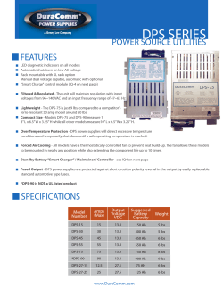
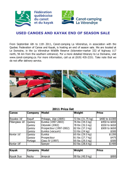
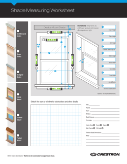
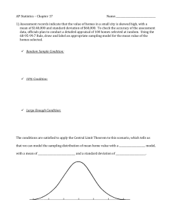
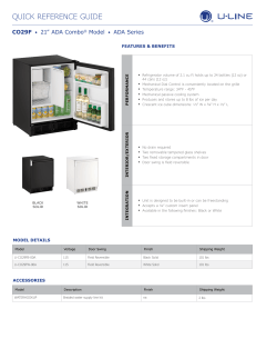
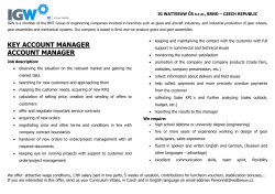
Trailer
Products
Catalog
Landing Gear
Kingpins
Turntables
Fifth Wheels
For Converter Dollies
1770 Hayes St.
Grand Haven, MI 49417
800-253-5105
Fax: 616-846-0310
www.jostinternational.com
Table Of Contents
Landing Gear Product Line..................................................................................................1
A400 Series................................................................................................................2
A440 Series................................................................................................................4
A450 Series................................................................................................................6
H450 Series................................................................................................................8
UL500 Series............................................................................................................10
AX100 Series............................................................................................................12
AD500 Series............................................................................................................14
Parts Guide...............................................................................................................16
Kingpin Product Line..........................................................................................................17
AAR Cruciform Style.................................................................................................18
SAE Mushroom Style................................................................................................20
SAE Spool Style........................................................................................................22
Bolt In Style..............................................................................................................24
Turntables................................................................................................................26
Fifth Wheel for Converter Dollies........................................................................................28
Landing Gear Product Line
Static Load Capacity*
Lift Capacity
Side Load Capacity*
Standard
Magnum 5 Year
Magnum 10 Year
Heavy Duty 10 Year
Ultralight
Alumilight
A400
A440
A450
H450
UL500
AX100
160,000 lbs
55,000 lbs
29,000 lbs
170,000 lbs
62,500 lbs
33,000 lbs
170,000 lbs
62,500 lbs
33,000 lbs
200,000 lbs
70,000 lbs
33,000 lbs
160,000 lbs
50,000 lbs
26,000 lbs
160,000 lbs
55,000 lbs
29,000 lbs
*When properly braced on a trailer
Meets all TTMA & AAR Specifications
Features
Benefits
No External Gearbox
Gears Protected and No Shaft Misalignment
All Austempered Ductile Iron Gears
Gears Will Not Wear Out
Spline Shifting
Easy Shifting
Double "D" Crank
Transfers Crank Torque Directly Into Shaft
High Gear 3.5 Turns/Inch
Low Gear 32 Turns/Inch
1
Design Features
•
Internal gearbox protects gears
and prevents shaft misalignment.
•
Cover and bushings sealed to
keep moisture out.
•
Double "D" style shaft allows
crank force to go directly into the
gearbox, not torquing the bolt.
•
10 bolt mounting pattern adds
mounting rigidity.
•
Reinforcing strap at the bottom
of the upper housing for added
strength.
•
Austempered ductile iron gears
will not wear out.
Capacities & Ratings
Maximum Static Load Rating*
160,000 lbs
Rated Lift Capacity**:
55,000
Side Load Capacity*:
29,000 per set
*When properly braced on a trailer.
**With 100ft-lbs input torque.
Gear Ratio
Low Gear: 32 Turns = 1˝ Travel
High Gear: 3.5 Turns = 1˝ Travel
2
Product Information
A 4 0 0 . G .17
Mounting
Style
Series
A40
Leg Speed
Footwear
Travel
14 - 14˝ Travel
17 - 17˝ Travel
19 - 19˝ Travel
Outside Mount - 0
Frame Width
4.5˝
4.5˝
Cushion Foot
Cross Shaft
Length
G1
G3
G8
12˝x12˝
10˝x10˝
12˝x12˝
G
Leave Blank To Order a Set
Gear Side Leg Only - R
Non-Gear Side Leg Only - L
Inside Mount - 1
5.7˝
2.8
10˝x10˝
Standard
Frame Width
10.3˝
Low Profile
Sand Shoe
10.3˝
10
T
T2
T1
10˝x10˝
10˝x12˝
10˝x10˝
T3
Cross Shaft
Length
4.5˝˝
1.5˝
Standard
Cross Shaft
Crank Hanger
10˝x12˝
Low Profile
Travel Dimensions
9˝
7.5˝
1.0˝
Length
2.25˝ typ.
2.75˝
.75˝
1.0˝
Example: B10363.56.5
B10261
Mount Style
Overall Length (in)
Inside Mount - B10363
Outside Mount - B10066
Standard Inside Mount = 56.5˝
Standard Outside Mount = 68.4˝
21
/32˝ Dia.
C
Upper
Housing
Note on Determining Length:
Inside Mount= Frame Width - 19.5˝
Outside Mount= Frame Width - 7.6˝
A
Retracted
B
Extended
Crank Handle
Sidefold
From End of
Input Shaft
Length
Standard
From End of
Input Shaft
Length
D
Travel
14˝
Shoe Style
Example : C10592.1
Standard- C10592
Sidefold - C10591
D
Travel
Length
1 - 5¼˝
2 - 8¼˝ (Standard)
3 - 10½˝
4 - 17¾˝
5 - 14¾˝
Extended
Retracted
Extended
Retracted
Extended
Retracted
C
Upper
Hsg.
14
42 ⅝˝
28 ⅝˝
40 ⅛˝
26 ⅛˝
39 ¾˝
25 ¾˝
21 15⁄16˝
17
48 ⅝˝
31 ⅝˝
46 ⅛˝
29 ⅛˝
45 ¾˝
28 ¾˝
24 15⁄16˝
19
52 ⅝˝
33 ⅝˝
50 ⅛˝
31 ⅛˝
49 ¾˝
30 ¾˝
26 15⁄16˝
T, T2, G, G1
T1, T3
G3, G8
3
Design Features
•
Elevating screw is fully encased in
a grease tube.
•
Legs are completely sealed and all
shafts have seals to keep moisture
out.
•
Double "D" style shaft allows
crank force to go directly into the
gearbox, not torquing the bolt.
•
Gearbox is completely filled with
low temperature grease.
•
Austempered ductile iron gears
will not wear out.
•
10 bolt mounting pattern adds
mounting rigidity.
•
Reinforcing strap at the bottom
of the upper housing for added
strength.
Capacities & Ratings
Maximum Static Load Rating*
170,000 lbs
Rated Lift Capacity**:
62,500 lbs
Side Load Capacity*:
33,000 lbs per set
*When properly braced on a trailer.
**With 100ft-lbs input torque.
Gear Ratio
Low Gear: 32 Turns = 1˝ Travel
High Gear: 3.5 Turns = 1˝ Travel
4
Product Information
A 4 4 0 . G .17
Mounting
Style
Series
A44
Leg Speed
Footwear
Travel
14 - 14˝ Travel
17 - 17˝ Travel
19 - 19˝ Travel
Outside Mount - 0
Frame Width
4.5˝
4.5˝
Cushion Foot
Cross Shaft
Length
G1
G3
G8
12˝x12˝
10˝x10˝
12˝x12˝
G
Leave Blank To Order a Set
Gear Side Leg Only - R
Non-Gear Side Leg Only - L
Inside Mount - 1
5.7˝
2.8˝
10˝x10˝
Standard
Sand Shoe
Frame Width
10.3˝
Low Profile
10.3˝
10
T
T2
T1
10˝x10˝
10˝x12˝
10˝x10˝
T3
Cross Shaft
Length
4.5˝
1.5˝
Standard
Cross Shaft
Crank Hanger
10˝x12˝
Low Profile
Travel Dimensions
9˝
7.5˝
1.0˝
Length
2.25˝ typ.
2.75˝
.75˝
1.0˝
Example: B10363.56.5
B10261
Mount Style
Overall Length (in)
Inside Mount - B10363
Outside Mount - B10066
Standard Inside Mount = 56.5˝
Standard Outside Mount = 68.4˝
21
/32˝ Dia.
C
Upper
Housing
Note on Determining Length:
Inside Mount= Frame Width - 19.5˝
Outside Mount= Frame Width - 7.6˝
A
Retracted
B
Extended
Crank Handle
Sidefold
From End of
Input Shaft
Length
Standard
From End of
Input Shaft
Length
D
Travel
14˝
Shoe Style
Example : C10592.1
Standard- C10592
Sidefold - C10591
D
Travel
Length
1 - 5¼˝
2 - 8¼˝ (Standard)
3 - 10½˝
4 - 17¾˝
5 - 14¾˝
Extended
Retracted
Extended
Retracted
Extended
Retracted
C
Upper
Hsg.
14
42 ⅝˝
28 ⅝˝
40 ⅛˝
26 ⅛˝
39 ¾˝
25 ¾˝
21 15⁄16˝
17
48 ⅝˝
31 ⅝˝
46 ⅛˝
29 ⅛˝
45 ¾˝
28 ¾˝
24 15⁄16˝
19
52 ⅝˝
33 ⅝˝
50 ⅛˝
31 ⅛˝
49 ¾˝
30 ¾˝
26 15⁄16˝
T, T2, G, G1
T1, T3
G3, G8
5
Design Features
•
Increased lift nut hardness to
increase strength and reduce wear.
•
Elevating screw is fully encased in a
rechargeable powder coated grease
tube.
•
Legs are completely sealed and all
shafts have seals to keep moisture
out.
•
Double "D" style shaft allows crank
force to go directly into the gearbox,
not torquing the bolt.
•
Gearbox is completely filled with low
temperature grease.
•
Hole added to lower leg to access
grease fitting in rechargeable grease
tube. Replaceable cushion foot for
easy repair when worn or damaged.
•
Austempered ductile iron gears will
not wear out.
Capacities & Ratings
Maximum Static Load Rating*
170,000 lbs
Rated Lift Capacity**:
62,500
Side Load Capacity*:
33,000 per set
*When properly braced on a trailer.
**With 100ft-lbs input torque.
Gear Ratio
Low Gear: 32 Turns = 1˝ Travel
High Gear: 3.5 Turns = 1˝ Travel
6
Product Information
A 4 5 0 . G .17. 3 8
Mounting
Style
Series
A45
Leg Speed
Footwear
Travel
Option
Outside Mount - 0
4.5˝
4.5˝
38 - Removable Cushion Foot
*Available on G shoe styles only.
14 - 14˝ Travel
17 - 17˝ Travel
19 - 19˝ Travel
Frame Width
Cushion Foot
Cross Shaft
Length
G1
G3
G8
12˝x12˝
10˝x10˝
12˝x12˝
G
Leave Blank To Order a Set
Gear Side Leg Only - R
Non-Gear Side Leg Only - L
Inside Mount - 1
5.7˝
2.8˝
10˝x10˝
Standard
Low Profile
Frame Width
10.3˝
10.3˝
10
Sand Shoe
T
Cross Shaft
Length
T2
T1
T3
10˝x12˝
10˝x10˝
4.5˝˝
1.5˝
10˝x10˝
Standard
Cross Shaft
Crank Hanger
10˝x12˝
Low Profile
Travel Dimensions
9˝
7.5˝
1.0˝
Length
2.25˝ typ.
2.75˝
.75˝
1.0˝
Example: B10363.56.5
B10261
Mount Style
Overall Length (in)
Inside Mount - B10363
Outside Mount - B10066
Standard Inside Mount = 56.5˝
Standard Outside Mount = 68.4˝
21
/32˝ Dia.
C
Upper
Housing
Note on Determining Length:
Inside Mount= Frame Width - 19.5˝
Outside Mount= Frame Width - 7.6˝
A
Retracted
B
Extended
Crank Handle
Sidefold
From End of
Input Shaft
Length
Standard
From End of
Input Shaft
Length
D
Travel
14˝
Shoe Style
Example : C10592.1
Standard- C10592
Sidefold - C10591
D
Travel
Length
1 - 5¼˝
2 - 8¼˝ (Standard)
3 - 10½˝
4 - 17¾˝
5 - 14¾˝
Extended
Retracted
Extended
Retracted
Extended
Retracted
C
Upper
Hsg.
14
42 ⅝˝
28 ⅝˝
40 ⅛˝
26 ⅛˝
39 ¾˝
25 ¾˝
21 15⁄16˝
17
48 ⅝˝
31 ⅝˝
46 ⅛˝
29 ⅛˝
45 ¾˝
28 ¾˝
24 15⁄16˝
19
52 ⅝˝
33 ⅝˝
50 ⅛˝
31 ⅛˝
49 ¾˝
30 ¾˝
26 15⁄16˝
T, T2, G, G1
T1, T3
G3, G8
7
Design Features
•
10 Year Warranty
•
Elevating screw is fully encased
in a rechargeable powder coated
grease tube.
•
Legs are completely sealed and all
shafts have seals to keep moisture
out.
•
Double "D" style shaft allows
crank force to go directly into the
gearbox, not torquing the bolt.
•
Gearbox is completely filled with
low temperature grease.
•
Austempered ductile iron gears
will not wear out.
•
Reinforcing strap at the bottom
of the upper housing for added
strength.
•
Welded Thrust Collar
•
Heavy Duty Thrust Bearing
•
Available in all shoe styles.
Capacities & Ratings
Maximum Static Load Rating*
200,000 lbs
Rated Lift Capacity:
70,000 lbs
Side Load Capacity*:
33,000 lbs per set
*When properly braced on a trailer.
Gear Ratio
Low Gear: 32 Turns = 1˝ Travel
High Gear: 3.5 Turns = 1˝ Travel
8
Product Information
H 4 5 0 . G .17. 3 8
Mounting
Style
Series
H45
Leg Speed
Footwear
Travel
Cushion Foot
15 - 15˝ Travel
17 - 17˝ Travel
19 - 19˝ Travel
Outside Mount - 0
Sand Shoe
14 - 14˝ Travel
16 - 16˝ Travel
18 - 18˝ Travel
Frame Width
4.5˝
4.5˝
Cushion Foot
Cross Shaft
Length
G1
G3
G8
12˝x12˝
10˝x10˝
12˝x12˝
G
Leave Blank To Order a Set
Gear Side Leg Only - R
Non-Gear Side Leg Only - L
Inside Mount - 1
5.7˝
2.8
10˝x10˝
Standard
Frame Width
10.3˝
Low Profile
Sand Shoe
10.3˝
10
H
H2
H1
10˝x10˝
10˝x12˝
10˝x10˝
H3
Cross Shaft
Length
3.5˝
1.5˝
Standard
Cross Shaft
Crank Hanger
10˝x12˝
Low Profile
Travel Dimensions
9˝
7.5˝
1.0˝
Length
2.25˝ typ.
2.75˝
.75˝
1.0˝
Example: B10363.56.5
B10261
Mount Style
Overall Length (in)
Inside Mount - B10363
Outside Mount - B10066
Standard Inside Mount = 56.5˝
Standard Outside Mount = 68.4˝
21
/32˝ Dia.
C
Upper
Housing
Note on Determining Length:
Inside Mount= Frame Width - 19.5˝
Outside Mount= Frame Width - 7.6˝
A
Retracted
B
Extended
Crank Handle
Sidefold
From End of
Input Shaft
Length
Standard
From End of
Input Shaft
Length
D
Travel
14˝
D
D
Travel Travel
Example : C10592.1
Standard- C10592
Sidefold - C10591
Length
1 - 5¼˝
2 - 8¼˝ (Standard)
3 - 10½˝
4 - 17¾˝
5 - 14¾˝
Shoe Style
H, H2
H1, H3
G, G1
G3, G8
C
Upper
Hsg.
Cushion
Foot
Sand
Shoe
15
14
43 ⅝˝
29 ⅝˝
41 7⁄8˝
27 7⁄8˝
44 ⅝˝
29 ⅝˝
41 ¾˝
26 ¾˝ 23 15⁄16˝
17
16
47 ⅝˝
31 ⅝˝
45 7⁄8˝
29 7⁄8˝
48 ⅝˝
31 ⅝˝
45 ¾˝
28 ¾˝ 25 15⁄16˝
18
51 ⅝˝
33 ⅝˝
49 ⁄8˝
31 ⁄8˝
52 ⅝˝
33 ⅝˝
49 ¾˝
30 ¾˝ 27 15⁄16˝
19
Extended Retracted Extended Retracted Extended Retracted Extended Retracted
7
7
9
Design Features
•
The same trusted gearbox.
•
Legs are completely sealed to
keep moisture out.
•
HSLA flange material provides
low weight and increased
strength.
•
Double "D" style shaft allows
crank force to go directly into
the gearbox, not torquing the
bolt.
•
Available as UL540 Magnum
and UL550 10 yr Magnum.
•
HSLA material on both the
upper and lower tube provides
low weight and increased
strength.
Capacities & Ratings
Maximum Static Load Rating*
160,000 lbs
Rated Lift Capacity**:
50,000
Side Load Capacity*:
26,000 per set
*When properly braced on a trailer.
**With 100ft-lbs input torque.
Gear Ratio
Low Gear: 32 Turns = 1˝ Travel
High Gear: 3.5 Turns = 1˝ Travel
10
Product Information
U L 5 0 0 . G .17
Series
UL5
Mounting
Style
Grease
Package
Leg Speed
Travel
Footwear
Standard - 0
5 Year Maint. Free - 4
5 Year Maint. Free & 10 Year Warranty - 5
14 - 14˝ Travel
17 - 17˝ Travel
19 - 19˝ Travel
Cushion Foot
Outside Mount - 0
Frame Width
G
4.5˝
4.5˝
Leave Blank To Order a Set
Gear Side Leg Only - R
Non-Gear Side Leg Only - L
Cross Shaft
Length
G1
G3
G8
12˝x12˝
10˝x10˝
12˝x12˝
5.7˝
2.8˝
10˝x10˝
Standard
Inside Mount - 1
Sand Shoe
Frame Width
10.3˝
Low Profile
T
T2
T1
10˝x10˝
10˝x12˝
10˝x10˝
10.3˝
10
Cross Shaft
Length
T3
4.5˝
1.5˝
Standard
Cross Shaft
Crank Hanger
10˝x12˝
Low Profile
Travel Dimensions
9˝
7.5˝
1.0˝
Length
2.25˝ typ.
2.75˝
.75˝
1.0˝
Example: B10363.56.5
B10261
Mount Style
Overall Length (in)
Inside Mount - B10363
Outside Mount - B10066
21
/32˝ Dia.
Standard Inside Mount = 56.5˝
Standard Outside Mount = 68.4˝
C
Upper
Housing
Note on Determining Length:
Inside Mount= Frame Width - 19.5˝
Outside Mount= Frame Width - 7.6˝
A
Retracted
B
Extended
Crank Handle
Sidefold
From End of
Input Shaft
Length
Standard
From End of
Input Shaft
Length
D
Travel
14˝
Shoe Style
Example : C10592.1
Standard- C10592
Sidefold - C10591
D
Travel
Length
1 - 5¼˝
2 - 8¼˝ (Standard)
3 - 10½˝
4 - 17¾˝
5 - 14¾˝
Extended
Retracted
Extended
Retracted
Extended
Retracted
C
Upper
Hsg.
14
42 ⅝˝
28 ⅝˝
40 ⅛˝
26 ⅛˝
39 ¾˝
25 ¾˝
21 15⁄16˝
17
48 ⅝˝
31 ⅝˝
46 ⅛˝
29 ⅛˝
45 ¾˝
28 ¾˝
24 15⁄16˝
19
52 ⅝˝
33 ⅝˝
50 ⅛˝
31 ⅛˝
49 ¾˝
30 ¾˝
26 15⁄16˝
T, T2, G, G1
T1, T3
G3, G8
11
Design Features
•
Steel cover sealed with silicone to
keep moisture out.
•
Available in outside and inside mount.
•
6061-T6 extruded aluminum upper leg
for durability.
•
Standard JOST gear train allows easy
interchangeability.
•
A 3∕8˝ x 2˝ reinforcing strap for superior
side load strength.
•
Polyester coated HSLA steel lower leg.
•
All standard JOST ground members
available.
•
Available as AX140 Magnum and
AX150 10 yr Magnum.
Capacities & Ratings
Maximum Static Load Rating*
160,000 lbs
Rated Lift Capacity**:
55,000
Side Load Capacity*:
29,000 per set
*When properly braced on a trailer.
**With 100ft-lbs input torque.
Gear Ratio
Low Gear: 32 Turns = 1˝ Travel
High Gear: 3.5 Turns = 1˝ Travel
12
Product Information
A X 1 0 0 . G .17
Series
AX1
Mounting
Style
Grease
Package
Leg Speed
Travel
Footwear
Standard - 0
5 Year Maint. Free - 4
5 Year Maint. Free & 10 Year Warranty - 5
15 - 15˝ Travel
17 - 17˝ Travel
19 - 19˝ Travel
Outside Mount - 0
Cushion Foot
G
G1
Frame Width
4.5˝
4.5˝
Leave Blank To Order a Set
Gear Side Leg Only - R
Non-Gear Side Leg Only - L
Cross Shaft
Length
G8
1.5˝
3.88˝
10˝x10˝
Inside Mount - 1
12˝x12˝
10˝x10˝
12˝x12˝
Sand Shoe
T3
T1
Frame Width
10.3˝˝
G3
10.3˝
10.3
3.0˝
3.5˝
10˝x10˝
10˝x12˝
Cross Shaft
Length
Cross Shaft
Crank Hanger
Travel Dimensions
9˝
7.5˝
1.0˝
Length
2.25˝ typ.
2.75˝
.75˝
1.0˝
Example: B10363.56.5
12390
Mount Style
21
/32˝ Dia.
Overall Length (in)
Inside Mount - B10363
Outside Mount - B10066
Standard Inside Mount = 56.5˝
Standard Outside Mount = 68.4˝
C
Upper
Up
Housing
Hou
Note on Determining Length:
Inside Mount= Frame Width - 19.5˝
Outside Mount= Frame Width - 7.6˝
A
Retracted
B
ed
Extended
Crank Handle
Sidefold
From End of
Input Shaft
Length
Standard
From End of
Input Shaft
Length
D
Travel
14˝
Shoe Style
Example : C10592.1
D
T1
Travel
Standard- C10592
Sidefold - C10591
Length
1 - 5¼˝
2 - 8¼˝ (Standard)
3 - 10½˝
4 - 17¾˝
5 - 14¾˝
T3
G, G1
C
G3, G8
Extended Retracted Extended Retracted Extended Retracted Extended Retracted
Upper
Hsg.
15
44 7⁄16˝ 29 7⁄16˝
44 7⁄8˝
29 7⁄8˝
45 5⁄16˝ 30 5⁄16˝
42 1⁄2˝
27 7⁄8˝
25 7⁄16˝
17
48 ⁄16˝ 31 ⁄16˝
48 ⁄8˝
31 ⁄8˝
49 ⁄16˝ 32 ⁄16˝
46 ⁄2˝
29 ⁄8˝
27 7⁄16˝
19
52 ⁄16˝ 33 ⁄16˝
52 ⁄8˝
33 ⁄8˝
53 ⁄16˝ 34 ⁄16˝
50 ⁄2˝
31 ⁄8˝
29 7⁄16˝
7
7
7
7
7
7
7
7
5
5
5
5
1
1
7
7
13
Design Features
•
25" Travel
Capacities & Ratings
•
60,000 psi, minimum yield
high strength low alloy steel.
Load Capacity*:
20,000 lbs per leg
•
Holes placed every 2" for
precise height adjustment.
•
8 bolt formed mounting
flange reinforced to add
mounting rigidity.
•
Double reinforcing strap
at the bottom of the upper
housing for added strength.
•
Each leg weighs only 62 lbs.
*When properly braced on a trailer.
Travel Dimensions
9˝
7.5˝
2.25˝ typ.
21
/32˝ Dia.
Up
Upper
p
Hou
Housing
u
29
29.42"
.
Retracted
29.73"
Extended
54.76"
Legs need to be
ordered individually.
14
Travel
25"
Pin Assembly
Part # 12195
Notes
15
Parts List for All Models
15
17
18
19
15
27
24
14
28
13
16
18
12
13
19
16
26
12
18
31
18
11
19
19
11
30
20
21
25
32
29
11
35
22
23
24
19
1
34
33
18
2
6
6
5
5
36
37
4
38
3
7
8
9
10
16
Item
Part Number
Description
Item
Part Number
Description
1
Please Call Sales
Single Speed Upper Weldment
20
C10177
Pinion Gear
2
Please Call Sales
Two Speed Upper Weldment
21
B10130
Single Speed Input Shaft
3
Please Call Sales
Lower Leg Assembly, Sand Cushion Foot
22
A10054.3
Roll Pin
4
Please Call Sales
Lower Leg Assembly, Sand Shoe
23
A10054.6
Roll Pin
5
A10101
Collar
24
A10218
Washer
6
Please Call Sales
Thrust Bearing
25
A10500
Button Plug
7
Please Call Sales
Sand Shoe
26
C10078
Output Spur Gear
8
A10037.3
Hex Head Cap Screw
27
A10260.1
Spiral Pin
9
A10038.7
Lock Nut
28
C10085
Spur Idler Gear
10
B10036
Axle
29
B10236
Two Speed Input Shaft
11
A10040
Grease Fitting
30
C10234
Output Cluster Gear
12
A10102
Thrust Washer
31
A10212
Two Speed Idler Shaft
13
C10259
Bevel Gear
32
B10285
Shifter Assembly
14
C10259
Single Speed Cover
33
A10038.6
Lock Nut
15
A10059.1
Cover Screw
34
A10230
Shifter Housing Bolt
16
A10052.3
Grooved Pin
35
A10054.7
Roll Pin
17
C10217
Two Speed Cover
36
C10262
Brace Lug - Flat
18
A10283
Shaft Seal
37
C10263
Brace Lug - 90°
19
A10255
Shaft Bushing
38
C10108
Brace Lug - "W" (Standard)
Part Number
AAR Cruciform
KZ AAR-X2-2.4
KZ AAR-X3-2.4
KZ AAR-X4-2.4
KZ AAR-X2-3.6
KZ AAR-X3-3.6
KZ AAR-X4-3.6
Part Number
KZ T2
KZ T3
KZ T4
KZ T5
KZ T6
Bolster Plate Thickness
1/4”
5/16”
3/8”
1/4”
5/16”
3/8”
Bolster Plate Thickness
1/4”
5/16”
3/8”
1/2”
5/8”
SAE Mushroom
SAE Spool
Part Number
Bolster Plate Thickness
KZ S2-2.0
KZ S3-2.0
KZ S4-2.0
KZ S5-2.0
KZ S2-2.9
KZ S3-2.9
KZ S4-2.9
KZ S5-2.9
1/4”
5/16”
3/8”
1/2”
1/4”
5/16”
3/8”
1/2”
Part Number
Bolster Plate Thickness
KZ 1007
KZ 1008
KZ 1010
KZ 1012
1/4” (7mm)
5/16” (8mm)
3/8” (10mm)
1/2” (12mm)
Bolt In
17
AAR kingpins are suitable for OEM and aftermarket replacement. They are intended to
be installed by welding, using a procedure published by the American Welding Society
or other technical organization. When properly installed they will meet or exceed the
performance requirements of the American Association of Railroads (AAR) standard
M-931 as well as the Society of Automotive Engineers (SAE) and the Truck and Trailer
Manufacturers Association (TTMA).
Technical Specifications
18
•
MATERIAL – AISI 4320H
•
HEAT TREATMENT
Through hardened using a quench and temper
process, which produces a surface hardness of 380420 BHN.
•
STRENGTH
At the above hardness the material will have an
approximate 190,000 psi ultimate strength and
145,000 psi yield strength.
•
IMPACT AND WEAR RESISTANCE
The high nickel alloy and heat treat process provides
a good balance between hardness (wear resistance)
and low brittleness (good impact resistance).
•
QUALITY ASSURANCE
Rigid metallurgical cleanliness and quality standards
including:
- 100% Brinell Hardness testing.
- 100% magnetic particle inspection.
- 100% ultrasonic testing (MS105, tightened C = 0).
Product Information
Cruciform Style - 4320H Steel Forging
+.12
D -.03
5 1∕2"
2 7∕8"
A
B
C
2 3∕4"
2"
∕16"
9
2 3∕4"
2 13∕16"
5 1∕2"
Part Number
Bolster Plate
Thickness
Weight
A
B
C
D
KZ AAR-X2-2.4
1/4"
15 lbs.
1.558"
3.012"
3.574"
2.44"
KZ AAR-X3-2.4
5/16"
15 lbs.
1.620"
3.074"
3.636"
2.44"
KZ AAR-X4-2.4
3/8"
15 lbs.
1.683"
3.137"
3.699"
2.44"
3.46"
KZ AAR-X2-3.6
1/4"
18 lbs.
1.547"
3.001"
3.563"
KZ ARR-X3-3.6
5/16"
18 lbs
1.310"
3.064"
3.626"
3.46"
KZ AAR-X4-3.6
3/8"
18 lbs.
1.683"
3.137"
3.699"
3.46"
19
SAE kingpins are suitable for OEM and aftermarket replacement. They are intended to
be installed by welding, using a procedure published by the American Welding Society
or other technical organization. When properly installed they will meet or exceed the
performance requirements of the Society of Automotive Engineers (SAE) and the Truck
and Trailer Manufacturers Association (TTMA).
Technical Specifications
20
•
MATERIAL – AISI 8630H
•
HEAT TREATMENT
Through hardened using a quench and temper
process, which produces a surface hardness of 302363 BHN.
•
STRENGTH
At the above hardness the material will have an
approximate 150,000 psi ultimate strength and
115,000 psi yield strength.
•
IMPACT AND WEAR RESISTANCE
The high nickel alloy and heat treat process provides
a good balance between hardness (wear resistance)
and low brittleness (good impact resistance).
•
QUALITY ASSURANCE
Rigid metallurgical cleanliness and quality standards
including:
- 100% Brinell Hardness testing.
- 100% magnetic particle inspection.
- 100% ultrasonic testing (MS105, tightened C = 0).
Product Information
Mushroom Style - 8630H Steel Forging
8" Dia.
Bolster
Plate
Thickness
.63 Min.
.38 Min.
1.308"
2 7∕8" Dia.
2.762"
3.324"
2" Dia.
2 13∕16" Dia.
Part Number
KZ T2
KZ T3
KZ T4
KZ T5
KZ T6
Bolster Plate
Thickness
1
∕4"
5
∕16"
3
∕8"
1
∕2"
5
∕8"
Weight
14 lbs.
14 lbs.
14 lbs.
14 lbs.
14 lbs.
21
SAE kingpins are suitable for OEM and aftermarket replacement. They are intended to
be installed by welding, using a procedure published by the American Welding Society
or other technical organization. When properly installed they will meet or exceed the
performance requirements of the Society of Automotive Engineers (SAE) and the Truck
and Trailer Manufacturers Association (TTMA).
Technical Specifications
22
•
MATERIAL – AISI 8630H
•
HEAT TREATMENT
Through hardened using a quench and temper
process, which produces a surface hardness of 302363 BHN.
•
STRENGTH
At the above hardness the material will have an
approximate 150,000 psi ultimate strength and
115,000 psi yield strength.
•
IMPACT AND WEAR RESISTANCE
The high nickel alloy and heat treat process provides
a good balance between hardness (wear resistance)
and low brittleness (good impact resistance).
•
QUALITY ASSURANCE
Rigid metallurgical cleanliness and quality standards
including:
- 100% Brinell Hardness testing.
- 100% magnetic particle inspection.
- 100% ultrasonic testing (MS105, tightened C = 0).
Product Information
Spool Style - 8630H Steel Forging
3 1∕4" Dia.
2 7∕8" Dia.
.350"
A
8" Dia.
Bolster
Plate
Thickness
.63 Min.
2 7∕8" Dia.
1.308"
2.762"
2" Dia.
3.324"
2 13∕16" Dia.
Part Number
Bolster Plate Dimension
Thickness
A
Weight
KZ S2-2.0
1
∕4"
2"
16 lbs
KZ S3-2.0
5
∕16"
2"
16 lbs
KZ S4-2.0
3
2"
16 lbs
KZ S5-2.0
1
2"
16 lbs
KZ S2-2.9
1
∕4"
7
2 ∕8"
18 lbs
KZ S3-2.9
5
∕16"
7
2 ∕8"
18 lbs
KZ S4-2.9
3
2 7∕8"
18 lbs
KZ S5-2.9
1
7
18 lbs
∕8"
∕2"
∕8"
∕2"
2 ∕8"
23
JOST bolt in kingpins are suitable for OEM and aftermarket replacement. Once the retention plate is installed the kingpin can
be easily replaced in minutes by just removing the mounting bolts. The retention plate is intended to be incorporated into the
design of the upper coupler structure similar to that of an SAE mushroom style weld in kingpin. It must be welded using a
procedure published by the American Welding Society, or other technical organization.
When properly installed bolt in kingpins will meet or exceed the performance requirements of the Federal Motor Carrier
Safety Regulations (FMCSR), The Society of Automotive Engineers (SAE) and the Truck and Trailer Manufacturers Association
(TTMA).
Design Features
24
•
Bolt in kingpins allow for easy and fast
replacement of the kingpin, and at much
less cost than weld in kingpins.
•
The kingpin flange and bolts are
recessed in the retention plate reducing
the possibility of center loading of the
fifth wheel.
•
JOST kingpins are manufactured and
inspected using the most stringent
safety requirements.
•
The retention plate is manufactured
from ST-52-3 Steel (similar to ASTM
A572 Grade 50).
Product Information
Bolt In Style Kingpin
10 1∕4" Dia.
Part Number
9 1∕4" Dia.
7 7∕8" Dia.
7
5 ∕8" Dia.
Dimension A
Dimension B
Bolster Plate
KZ 1007
1
∕4" (7 mm)
1 15∕32" (37 mm)
KZ 1008
5
∕16" (8 mm)
1 15∕32" (37 mm)
KZ 1010
3
∕8" (10 mm)
1 11∕32" (34 mm)
KZ1012
1
1 5∕16" (33 mm)
∕2" (12 mm)
B
A
8 x M14 Bolts
140 ± 8 Ft-lbs Torque
3.324"
2" Dia.
A
Assembly
Retention Plate (A) Kingpin (B)
Bolt (C)
Part Number
Part Number
Part Number Part Number
KZ 1007
KZ 1007-02
KZ 1012-01
KZ 1012-03
KZ 1008
KZ 1008-02
KZ 1012-01
KZ 1012-03
KZ 1010
KZ 1010-02
KZ 1012-01
KZ 1012-03
KZ 1012
KZ 1012-02
KZ 1012-01
KZ 1012-03
B
The kingpin retention plate installation must conform to SAE
and TTMA recommended practices.
Bolts must be tightened and properly torqued as described
in the product information details. For safety reasons the
bolts should only be tightened and torqued once. If removed
they should be replaced.
C
25
Single row ball bearing turntables are for trailers and
agricultural vehicles, connecting the A-frame to the trailer
chassis. The turntable allows the axle to turn relative to the
trailer frame transferring both the axial, and radial forces. The
lower (outer) ring is bolted to the A-frame and the upper ring
(inner) ring is bolted to the chassis.
Double row ball turntables
guarantee optimum distribution
of the axial and radial forces. This
design has proven through years of
different applications. Double row
ball turntables are used in particular
when the vehicle application
requires both precision and strength
in design and material.
26
Product Information
B
L and N Style Turntables
F
Application:
D
G
L Series: Farm vehicles and trailers up to 15 mph.
N Series: Farm vehicles and trailers over 15 mph.
All load data for L and N series applies to use on paved roads in steering systems.
H
Specifications: Standard Lubrication, Undrilled
G
G
H
Weight
(lbs)
Axial Load
Ton (Short)
⁄16"
C
E
A
Type
A
B
C
D
E
F
400L
15 3∕4"
13 7∕16"
11 1∕2"
500L
11
19 ∕16"
650L
25 9∕16"
B
14 3∕4"
10 1∕4"
5
1 3∕4"
23
0.84
17 ∕8"
15 ∕16"
13"
11
18 ∕16"
3
14 ∕16"
5
3
1 ∕4"
31
1.01
23 5∕16"
21 5∕16"
18 7∕8"
24 5∕8"
20 1∕16"
5
1 3∕4"
41
1.69
13
9
3
29 ∕2"
27 ∕4"
25 ∕4"
22 ∕16"
28 ∕16"
24"
1 ∕4"
47
2.02
850L
33 7∕16"
31 3∕16"
29 3∕16"
26 3∕4"
32 1∕2"
27 15∕16"
5
1 3∕4"
55
2.81
500N
19 11∕16"
17 3∕16"
15 1∕8"
12 3∕8"
18 11∕16"
13 3∕8"
5
2 1∕16"
47
2.02
650N
25 9∕16"
23 1∕8"
21"
18 5∕16"
24 5∕8"
19 5∕16"
5
2 1∕16"
57
2.81
750N
29 ½"
1
27 ∕16"
15
24 ∕16"
1
850N
33 7∕16"
31"
28 7∕8"
15
13
37 ∕8"
34 ∕16"
1
⁄16"
750L
3
1
⁄16"
5
950N
1
9 1∕16"
7
3
32 ∕16"
1
⁄16"
⁄16"
⁄16"
22 ∕4"
9
28 ∕16"
23 ∕4"
5
2 ∕16"
65
3.37
26 3∕16"
32 1∕2"
27 3∕16"
5
2 1∕16"
74
3.93
5
1
82
4.5
1
30 ∕8"
7
36 ∕16"
1
⁄16"
1
31 ∕8"
⁄16"
⁄16"
⁄16"
2 ∕16"
HE Style Turntables
F
G
D
Application:
The specified axle load relates to use where the turntable is mounted on the front axle
of a trailer with three axles travelling at speeds of up to 65 mph.
On dual-axle trailers, the specified axle loads can be exceeded by 10% (20% at
speeds below 18 mph).
H
Specifications: Standard Lubrication, Drilled, Primed
C
G
H
Weight
(lbs)
Axial Load
Ton (Short)
3 9∕16"
138
11.24
E
A
B
Type
A
B
C
D
E
F
HE1000-22
39 3∕8"
39 13∕16"
34 7∕8"
33 15∕16"
37 13∕16"
38 3∕8"
G
3
∕8"
DK Style Turntables
F
D
G
H
Application:
The specified axial load applies to vehicles travelling up to 65 mph. A 25% higher axial
load is permitted for vehicles with speeds below 18 mph. Please contact JOST if the
application will have off-center loads or in applications where there is more than a 360
rotation.
Specifications: Standard Lubrication, Drilled, Primed
C
G
E
Type
A
B
C
D
E
F
DK 90/12
38 7∕8"
39 3∕8"
34 5∕16"
32 13∕16"
37 1∕2"
38 1∕16"
DK 90/16
43 1∕8"
43 5∕8"
38 9∕16"
37 1∕8"
41 3∕4"
42 5∕16"
A
H
Weight
(lbs)
Axial Load
Ton (Short)
3
3 9∕16"
158
13.22
3
3 9∕16"
180
17.63
G
∕8"
∕8"
27
For Your Converter Dolly
The JOST JSK37010 is ideal for use in converter dolly applications. It is specially designed to reduce
damage from the kingpin in the event of a miscouple. The JSK37010 includes all the same features
as the standard JSK37 series with the added protection of a drop handle and internal adjustment.
Design Features
Drop Handle
•
Drop handle to prevent kingpin
damage.
•
Internal adjustment to prevent
kingpin damage.
•
Includes all the features of the
JSK37 series.
•
Same jaw rebuild kit as all other
JSK37 series wheels.
Internal Adjustment
Capacities & Ratings
Maximum Vertical Rating
50,000 lbs
Maximum Horizontal Rating
150,000 lbs
28
Product Information
Available Standard Mounts
PM Mount
XM Mount
AM Mount
DB Mount
*For ordering information and part numbers please contact customer support at 800-253-5105.
Please see our Fifth Wheel Catalog for our full line of fifth wheel products.
29
The reasons are simple.
History of JOST
1952
Establishment of the factory for turntables in Neu-Isenburg, Germany
1956
JOST begins production of fifth wheels
1960
Production begins in South Africa
Foundation of Great Britain Ltd. JOST
1970
Foundation of JOST Italia S.R.I.
Foundation of JOST South Africa (Pty.) Ltd
Foundation of JOST France
Foundation of JOST Belgium NV
1980
Foundation of JOST International Corp. in Grand Haven, Michigan
Foundation of JOST Iberica, Spain
Foundation of Australia Pty JOST Ltd
Landing gear production doubles
1990
JOST International in Grand Haven Begins landing gear production
Foundation of JOST Far East Pte. Ltd
Foundation of China JOST
Foundation of JOST Brazil
Foundation of Hungaria
New product offerings for the container equipment and intermodal equipment introduced
2000
Fifth wheel production begins in Greeneville, Tennessee
JOST acquires the Rockinger product line of tow bars and trailer hitches in Germany
Foundation of JOST Rus
Acquisition of REGENSBURGER
Acquisition of Tridec Steering Solutions
Foundation of JOST India
Foundation of JOST Polska
2012
Foundation of JOST Japan
Acquisition of Edbro Hydraulic Systems
JOST International
1770 Hayes Street
Grand Haven, MI 49417
Ph. 800-253-5105
Fax (616) 846-0310
www.jostinternational.com
SL-TP-001 Rev. A


© Copyright 2026