
INSERTING HARDWARE POST
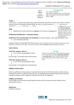
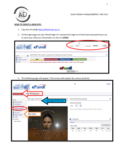
FDM BEST PRACTICE:
INSERTING HARDWARE POST-BUILD
SOFTWARE/PRODUCT/FINISHING
OVERVIEW
Various types of hardware are commonly used in plastic parts to withstand the torque
and load applied when joining parts to create assemblies (Figure 1). Like machined or
molded plastics parts, components made with FDM® technology can also have
hardware inserted into them.
Reference materials: -Y
• Processes
- Best Practice: Embedding Hardware
- Best Practice: Bonding
Inserts may be added during an FDM build (see the Best Practice: Embedding
Hardware) or in a secondary, post-build operation (Figure 2). This Best Practice covers
secondary insertion of hardware with common methods such as adhesive bonding,
press fitting and heat setting.
Applications where inserting hardware adds enhanced functionality include:
• Thread reinforcement
-- Threaded inserts
• Knurled (Figure 3)
• Expansion (Figure 4)
• Helical insert (Figure 5)
Figure 1: Brass threaded inserts installed
in an FDM part.
• Wear reduction
-- Bushing (Figure 6)
-- Bearing (Figure 7)
-- Wear plate
• Component alignment
-- Locating pin (Figure 8)
Figure 2: Brass threaded insert with screw.
• Over-torque prevention
-- Compression-limiting insert (Figure 9)
Figure 3: Knurled and barbed heat-set
brass threaded insert.
FDM BEST PRACTICE:
PAGE 2
INSERTING HARDWARE POST-BUILD
1.OPTIONS
1.1Methods
•
Adhesive bond: This technique requires applying an adhesive to the
insert and then mechanically inserting it into the FDM part. This is
commonly used when dealing with delicate hardware such as thermally or
mechanically sensitive components.
• Press fit: This technique requires mechanical insertion of the hardware
into the FDM part using an interference fit. This is commonly used when
dealing with expansion inserts.
•
Figure 4: Expansion insert.
Heat set (metallic inserts only): This is the preferred method for thermally
conductive hardware. Using heat to embed hardware into a thermoplastic
allows the plastic to conform to the insert and it relieves stress from the
interface during insertion.
NOTE: Follow manufacturer recommendations for design when using
these methods.
1.2 FDM material considerations
• Nylon 12: Best suited for interference style inserts such as compression
inserts and helical inserts.
• Polycarbonate (PC): Retains surface stress and is therefore best suited
for the low-stress or stress-relieving application methods such as adhesive
bonding or heat set.
Figure 5: Helical insert.
Figure 6: Wear-reduction bushing.
FDM BEST PRACTICE:
PAGE 3
INSERTING HARDWARE POST-BUILD
2.PROCESS
2.1 Adhesive bond
STEP 1: Oversize the hole diameter in the CAD model or STL by the required
clearance for the insert and the adhesive.
TIP: Use a 0.127 mm (0.005 in) clearance between inserts and FDM
components for adhesive unless otherwise specified by the manufacturer or
required by design specifications.
Figure 7: Bearings inserted into an FDM
part (ABS-M30™ black).
STEP 2:(Optional) Drill the hole to the proper diameter for the selected
insert.
STEP 3: Apply an adhesive, such as Click-Bond™ CB359 epoxy, to all
contact surfaces of the insert. For details, see the Best Practice:
Bonding.
Tip: Ensure chosen adhesive is compatible with substrate and
operating temperature.
Figure 8: Locating pins in an FDM mold
(PC white).
STEP 4: Place the insert into the cavity. Make sure the insert seats so
that it is parallel to the cavity walls.
Tip: When seating the insert, use a flat surface to press the hardware into
the FDM part while maintaining proper insert alignment.
STEP 5: Remove excess adhesive.
STEP 6: Allow the adhesive to cure per the manufacturer’s instructions.
STEP 7: Adhesive bond procedure complete.
Figure 9: Compression-limiting insert.
2.2 Press fit
STEP 1: Drill or ream the hole to ensure the proper cylindricity and diameter
for the selected insert.
STEP 2: Place the insert on top of the hole and align it under the arbor
press (Figure 10).
STEP 3: Compress the ram of the arbor press onto the insert and the FDM
part until the insert sits flush with the part’s surface.
STEP 4: Press fit procedure complete.
Figure 10: Press fitting arbor press.
FDM BEST PRACTICE:
INSERTING HARDWARE POST-BUILD
PAGE 4
2.3. Heat set
STEP 1: Drill or ream the hole to ensure the proper diameter for the
selected insert.
STEP 2:
Pre-heat the soldering iron or heat staking press to a temperature
that is approximately 170% of the glass transition temperature (Tg)
of the FDM material (Figure 11). For example, use a temperature of
288 °C (550 °F) for polycarbonate parts that have a Tg of
161 °C (322 °F).
Figure 11: Heat setting soldering iron.
NOTE: See the Stratasys material data sheets for glass transition
temperature values.
STEP 3: Place the soldering iron or heat stake on the insert. Allow the insert
to heat up and then apply light, constant pressure to make the insert
sit flush with the part’s surface.
TIP: If the heat set tool does not have temperature controls, simply apply
light pressure to the insert with the heated tip and wait for the insert to heat
to a temperature that will allow it to be inserted. Minimal pressure is required
when using a heated insertion method.
STEP 4: Heat set procedure complete.
FDM BEST PRACTICE:
INSERTING HARDWARE POST-BUILD
3.SAFETY
Observe manufacturer’s recommendations for safety, material handling and
storage. This information can be found in the Safety Data Sheet (SDS).
PAGE 5
FDM BEST PRACTICE:
INSERTING HARDWARE POST-BUILD
4.TOOLS & SUPPLIES
4.1Adhesive:
• Cyanoacrylate (Loctite® 495)
• Epoxy (Click-Bond CB359)
• Epoxy (Hysol® E-20HP)
4.2Tools:
• Heat stake press (Sonitek Model TS 100)
• Soldering iron (Weller ® EC1002)
• Arbor press (Dayton 1-Ton)
• Drill/reamer
4.3Inserts:
• Threaded insert (McMaster-Carr ® heat-set inserts for plastic)
• Threaded insert (McMaster-Carr press-fit expansion inserts for plastic)
• Helical insert (McMaster-Carr helical insert)
• Bushing (McMaster-Carr press-fit drill bushing)
• Bearing (McMaster-Carr flanged sleeve bearings)
• Locating pin (McMaster-Carr alignment dowels and pins)
• Compression limiting insert (McMaster-Carr press-fit bolt liners)
PAGE 6
FDM BEST PRACTICE:
INSERTING HARDWARE POST-BUILD
5.MATERIALS
With the exceptions noted in Section 1.2, all insertion methods are compatible with
all FDM materials.
CONTACT:
To obtain more information on this application,
contact:
Stratasys Application Engineering
1-855-693-0073 (U.S. toll-free)
+1 952-294-3888 (international)
[email protected]
Stratasys | www.stratasys.com | [email protected]
7665 Commerce Way
Eden Prairie, MN 55344
+1 888 480 3548 (US Toll Free)
+1 952 937 3000 (Intl)
+1 952 937 0070 (Fax)
2 Holtzman St.
Science Park, PO Box 2496
Rehovot 76124, Israel
+972 74 745-4000
+972 74 745-5000 (Fax)
ISO 9001:2008 Certified
© 2015 Stratasys. All rights reserved. Stratasys, Stratasys logo and FDM are registered trademarks of Stratasys Inc. ABS-M30 is a trademark of Stratasys, Inc. All other trademarks are
the property of their respective owners, and Stratasys assumes no responsibility with regard to the selection, performance or use of these non-Stratasys products. Product specifications
subject to change without notice. Printed in the USA. BP-FDM-InsertingHardware-01-15-EN
The information contained herein is for general reference purposes only and may not be suitable for your situation. As such, Stratasys does not warranty this information. For assistance
concerning your specific application, consult a Stratasys application engineer. To ensure user safety, Stratasys recommends reading, understanding, and adhering to the safety and usage
directions for all Stratasys and other manufacturers’ equipment and products. In addition, when using products like paints, solvents, epoxies, Stratasys recommends that users perform a
product test on a sample part or a non-critical area of the final part to determine product suitability and prevent part damage.
PAGE 7


© Copyright 2026