
RC-107K Instructions - Rod & Custom Motorsports
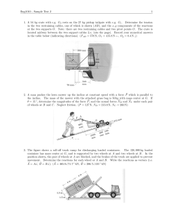
ROD & CUSTOM
Motorsports
INCORPORATED
RC-107K
Front Coilover Suspension Kit
Instruction Package
NOTE...
PLEASE READ ALL INSTRUCTIONS
INCLUDED WITHIN THIS PACKAGE.
IF AFTER READING YOU STILL NEED
ASSISTANCE PLEASE CALL THE TECH
LINE AT 843-629-1273.
MEASURE
HERE
C
L
MOUNTING BRACKET
(TYPICAL DRIVER &
PASSENGER SIDES)
CENTERLINE OF BRACKET
(BRACKET LENGTH / 2)
(Figure A)
1
FRAME RAIL
FRAME RAIL
CROSSMEMBER
CROSSMEMBER
CENTERLINE
MARK
CROSSMEMBER
CENTERLINE
MARK
THIS SIDE TO FRONT
NOTE 1 1/4" DIMENSION
APROX 1 1/4"
(Figure B)
HIGH SIDE
FACING FRONT
OF VEHICLE
(EXCEPT 1962-65 FAIRLANE,
SEE INSTRUCTIONS ABOVE)
SPRING POCKET
ALIGNED WITH
CROSSMEMBER
FRAME RAIL
CROSSMEMBER
(Figure C)
2
INSTALLATION TIP
Straight Edge Flush With
Top of Spring Pocket
Straight Edge Flush With
Top of Spring Pocket
Straight Edge
Straight Edge
Straight Edge
(Figure D)
3
If Bushings are not already Installed in rack...
Do Not Trim, This End is
Designed to Flair when
Bolts are Tightened.
This End to Crossmember
Inner Sleeve
4
(Figure E)
1 1/2" (Typ Both Sides)
(Sm. Block & BB)
F
B
I
E
F
D
D
C
E
K
A
E
I
J
D
G
H
E
Frame Rail
(Front to Rear View)
2"
Frame Rail
(Front to Rear View)
Mounting Bracket
(RC-030)
Mounting Bracket
(RC-030)
Big Block Setup
1 1/2"
PART
A
B
C
D
E
F
G
H
I
J
K
DESCRIPTION
SWAY BAR
SWAY BAR BRACKET
BOLT
I
CUP WASHER
BUSHING
NYLOCK
SLEEVE
BOLT
WASHER
BRACKET
BUSHING
D
R&C PART #
VARIES
RC-030
PRO-3
PRO-2
PRO-1
PRO-4
PRO-5
QUANTITY
1
2
2
8
8
6
2
4
4
2
2
5
Small Block Setup
NOTE PART # ON BOX
WELDS TO FRAME RAILS
3/8 - 16 X 7 LONG
SWAY BAR LINK
END LINK
3/8 - 16
END LINK, 2 5/8 LONG
3/8 - 16 X 1 LONG (GRADE 8)
3/8 FLAT
SWAY BAR MOUNTING BRACKET
SWAY BAR MOUNTING BUSHING
6
(Figure F)
B
A
N
L
I
J*
M
P
P
K
F
G
C
Q*
C
O
D
G
H
PART
A
B
C
D
E
F
G
H
I
J*
J*
K
L
M
N
O
P
Q*
Q*
DESCRIPTION
UPPER A-ARM
T-BOLT NUTS
T-BOLTS
LOWER A-ARM
LOWER A-ARM
NYLOCK
FLAT WASHER
BOLT
BOLT
COILOVER
COILOVER
SPACER, BALL JOINT
SPACER, BALL JOINT
CASTLE NUT
SPACER, COILOVER
BOLT
NYLOCK
SPINDEL
SPINDEL
R&C PART #
W-RC-410
W-RC-411L
W-RC-411R
DS531-07450
DS531-07550
RC-037
RC-119
RC-115
RC-124
RC-125
COAT WITH ANTI-SEIZE COMPOUND
BEFORE INSTALLATION, WRENCH TIGHTEN ONLY,
DO NOT TORQUE
QUANTITY
2
4
4
1
1
2
8
2
2
2
2
2
2
2
4
2
4
PAIR
PAIR
7
WITH BUSHINGS & BALL JOINTS INSTALLED
BAGGED TOGETHER
DRIVER SIDE LOWER A-ARM
PASSENGER SIDE LOWER A-ARM (NOT SHOWN)
1/2 - 13 (WRENCH TIGHTEN ONLY - DO NOT TORQUE)
1/2
1/2 - 13 X 12 LONG (GRADE 8) (COAT WITH ANTI-SEIZE)
1/2 - 13 X 2 1/2 LONG (GRADE 8)
*QA1 (SMALL BLOCK/MOD. ENGINE KIT)
*QA1 (BIG BLOCK ENGINE KIT)
LOWER BALL JOINT (3/8 THICK)
UPPER BALL JOINT (3/16 THICK)
INCLUDED WITH BALL JOINT
UPPER CONNECTION
1/2 - 20 X 2 LONG (GRADE 8)
1/2 - 20
STOCK HEIGHT (LEFT & RIGHT)
Customer Choice at
Time of Order
2" DROP (LEFT & RIGHT)
Front End Alignment Specs
Rod & Custom Motorsports MII Suspension Systems
Power Steering Specs:
Manual Steering Specs:
1/8" Toe-In
1/8" Toe-In
Definitions:
Camber is the inward or outward leaning of the top of the spindle when viewed from the front of the car.
Positive camber will occur when the top of the spindle leans outward toward the fender.
Negative camber will occur when the top of the spindle leans inward toward the engine.
Caster is the forward or rearward tilt of the top of the spindle centerline when viewed from the side of the car.
Positive camber will occur when the top of the spindle is leaning to the rear.
Negative caster will occur when the top of the spindle is leaning to the front.
Toe Setting is the straight line setting of the front wheels in relation to each other.
Toe-In will occur when the front sides of the tires are closer than the rear .
Toe-Out will occur when the rear sides of the tires are closer than the front.
Wheels & Tires Notes:
* For optimum tire clearance we STRONGLY recommend no wider than a 7 inch Wheel.
* 7 inch wide wheels need 4 to 4 1/2 inch backspacing.
* Some 14 inch wheels MAY work, some WILL NOT.
* 15, 16 & 17 inch tall wheels are acceptable.
* 8 inch wheels are possible BUT you will need to determine your backspacing DEAD ON!
8
QA1 Coilover Notes
QA1 shocks have 18 damping settings. There are 6 clicks per revolution and there are
3 revolutions. When the knob is set fully counter clockwise it is on the softest setting.
Start your adjustment from the softest setting. Recommended base settings to begin with
are as follows:
* 2 - 8 clicks for a nice ride and handling;
* 8-12 clicks for a firm ride and improved handling;
* 13 + clicks for more aggressive handling;
NOTE: DO NOT FORCE THE ADJUSTER KNOB. DO NOT USE PLIERS OR ANY OTHER TOOLS
ON THE PISTON ROD OR THE ADJUSTER KNOB. DO NOT EXCEED 18 CLICKS UNDER ANY
CIRCUMSTANCES. THIS WILL DAMAGE THE SHOCK AND CAUSE IT NOT TO ADJUST AND
WILL VOID ALL WARRANTIES. DO NOT USE THE SHOCK ABSORBER AS SUSPENSION.
UPPER COILOVER MOUNT IS ADJUSTABLE FOR SETTING RIDE HEIGHT.
Firmer
Softer
For additional information on your new QA1 Coilover Shocks, Please refer to the instruction/spec sheet
included in each QA1 box.
WARNING
BE EXTREEMLY CAREFUL WHEN TRANSPORTING (HAULING) YOUR VEHICLE. DAMAGE TO
THE FRONT SUSPENSION OCCUR IF A WINCH IS USED AND THE FRONT OF THE VEHICLE
IS PULLED DOWN HARD. THIS COMMONLY HAPPENS WHEN A ROLLBACK IS USED.
9


© Copyright 2026