
Model DA435HAR Air Compressor
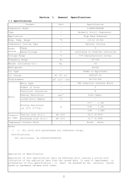
DA435HAR: 99900683:19980521 i Model DA435HAR Air Compressor (Dual Cooler - 10GPM) (Replaces Model 1154) IOWA MOLD TOOLING CO., INC. BOX 189, 500 HWY 18 WEST, GARNER, IA 50438 TEL: 515-923-3711 TECHNICAL SUPPORT FAX: 515-923-2424 MANUAL PART NUMBER 99900683 DA435HAR: 99900683:19980521 ii PRECAUTIONS Read before operating your compressor! DANGER EXPLODING TANK WILL CAUSE DEATH, SERIOUS INJURY OR PROPERTY DAMAGE 71393886 ● Drain air tank after each use to prevent moisture build-up and corrosion which leads to tank failure. ● Assure that tank and compressor relief valves work properly, and are at correct pressure settings. ● DO NOT modify or repair air tank. ● NEVER drive vehicle with pressure in air tank. DA435HAR: 99900683:19980223 iii TABLE OF CONTENTS PARA TITLE PAGE GENERAL INFORMATION INTRODUCTION ORDERING INFORMATION Section 1. SPECIFICATIONS 1-1. GENERAL 1-2. SPECIFICATIONS Section 2. INSTALLATION 2-1. GENERAL 2-2. PTO AND PUMP INSTALLATION 2-2-1. PTO INSTALLATION 2-2-2. DRIVELINE AND PUMP INSTALLATION 2-3. COMPRESSOR INSTALLATION Section 3. OPERATION 3-1. GENERAL 3-2. OPERATION Section 4. MAINTENANCE & PARTS 4-1. GENERAL Section 5. REPAIR 5-1. GENERAL 5-2. PISTON RING REPLACEMENT 5-3. OIL PUMP REPLACEMENT 5-4. CRANKSHAFT AND BEARING REPLACEMENT 5-5. CLUTCH REPLACEMENT 5-6. TROUBLESHOOTING Section 6. RELAY BOARD OPERATION 6-1. INTRODUCTION 6-2. OPERATION 6-2-1. IGNITION “ON” 6-2-2. REMOTE STARTING THE VEHICLE 6-2-3. REMOTE ENGINE STOP 6-2-4. REMOTE ENGINE SPEED (FROM CRANE) 6-2-5. COMPRESSOR ENGINE SPEED CONTROL(COMPRESSOR ONLY) 6-2-6. ENGINE SPEED CONTROL(CRANE&COMPRESSOR USED SIMULTANEOUSLY) 6-3. INSTALLATION 1-1 1-1 1-1 1-1 2-1 2-1 2-1 2-2 2-2 3-1 3-1 4-1 5-1 5-1 5-2 5-2 5-3 5-4 6-1 6-1 6-1 6-1 6-1 6-3 6-3 6-3 6-7 LIST OF ILLUSTRATIONS FIGURE TITLE B-1. B-2. B-3. D-1. PTO INSTALLATION DRIVELINE AND PUMP INSTALLATION COMPRESSOR MOUNTING HOLE DIMENSIONS ROUTINE MAINTENANCE CHECKLIST MOUNTING HARDWARE KIT OPTION-RELAY BOARD KIT COMPRESSOR ASSEMBLY WITH ENCLOSURE DA435 AIR COMPRESSOR OPTIONAL HYDRAULIC INSTALLATION KIT OPTIONAL INSTALLATION KIT WITH CRANE DRIVELINE MOUNTING OPTION REPAIR KITS KIT-REMOTE AIR FILTER PISTON RING ORIENTATION CYL HEAD TORQUE SEQUENCE BEARING HOUSING TORQUE SEQUENCE ROD ALIGNMENT TROUBLESHOOTING CHART BOTTOM VIEW OF RELAY INTERNAL WIRING RELAY BOARD-COMPONENTS & WIRING IGNITION “ON” REMOTE CONTROL HANDLE-TYPICAL REMOTE STARTING OF VEHICLE-IGNITION “ON” SPEED CONTROL-COMPRESSOR ONLY RELAY BOARD (77041378) WIRING INSTRUCTIONS E-1. E-2. E-3. E-4. E-5. F-1. F-2. F-3. F-4. F-5. F-6. F-7. F-8. PART NUMBER PAGE 2-1 2-2 2-2 4-1 4-2 4-3 4-3 4-5 4-8 4-8 4-9 4-9 4-10 5-1 5-1 5-3 5-3 5-4 6-1 6-1 6-2 6-4 6-4 6-5 6-6 6-7 DA435HAR: 99900683:19980223 iv DA435HAR: 99900683:19950918 1-1 GENERAL INFORMATION INTRODUCTION This manual provides information on the installation, operation and repair of the IMT Model DA435HAR Hydraulic Air Compressor. Three means are used throughout this manual to gain the attention of operating and service personnel. They are NOTES, CAUTIONS and WARNINGS and are defined as follows: NOTE A NOTE IS USED TO EITHER CONVEY ADDITIONAL INFORMATION OR TO PROVIDE FURTHER EMPHASIS FOR A PREVIOUS POINT. CAUTION A CAUTION IS USED WHEN THERE IS THE STRONG POSSIBILITY OF DAMAGE TO THE EQUIPMENT OR PREMATURE EQUIPMENT FAILURE. WARNING A WARNING IS USED WHEN THERE IS THE POTENTIAL FOR PERSONAL INJURY OR DEATH. Operate this equipment with respect and service it regularly for a safer working environment and longer equipment life. ORDERING INFORMATION When placing orders or requesting assistance, refer to the information below: TO BE COMPLETED BY DEALER CHASSIS INFORMATION TRANSMISSION MAKE: MODEL: PTO NUMBER: PTO %: COMPRESSOR AND HYDRAULIC PUMP INFORMATION COMPRESSOR MODEL: SERIAL NUMBER: PUMP MAKE: MODEL: RESERVOIR CAPACITY: ENGINE RPM: SECTION 1. SPECIFICATIONS 1-1. GENERAL The IMT DA435HAR air compressor is a single stage, air cooled, 4-cylinder, pressure lubricated, hydraulically driven unit, with a delivery rate of 35 CFM at 100 PSI. The magnetic clutch is engaged and disengaged by use of an air pressure sensing electric switch. The pressure switch is preset on factory installed units at approximately 120 psi to engage, and 150 psi to disengage. CAUTION OPERATING THE COMPRESSOR AT PRESSURES ABOVE 150 PSI WILL SHORTEN THE SERVICE LIFE AND VOID THE WARRANTY. 1-2. SPECIFICATIONS Power Source Bore Stroke Cylinder Configuration Dimensions Displacement Delivery Cooling Fan Diameter Operating Speed Lubrication Oil Capacity Weight Reservoir requirement Hydraulic Motor 2-5/8" 2-1/2" V4 26"L x 18"H x 18"W 44 CFM* 35 CFM* Air 14" 1400 RPM maximum Oil Pump 1-1/3 qts 200 lbs. 12 Gallon minimum * @ 1400 RPM - 100 PSI DA435HAR: 99900683:19970206 1-2 NOTES DA435HAR: 99900683:19930125 2-1 SECTION 2. INSTALLATION 2-1. GENERAL This section pertains to the installation of the IMT DA435HAR compressor, PTO and pump. The instructions are intended as a guide to assist you with your particular installation. These instructions will provide only general information. 2-2. PTO AND PUMP INSTALLATION The pump may either be installed directly on the PTO (see Figure B-1) or, as an optional method, it may be driven by a driveline (see Figure B-2). 2-2-1. PTO INSTALLATION Power take-off manufacturers provide specific installation instructions for their products. Those instructions should be followed when installing a PTO. Some trucks may require modification of the transmission cross-member to provide clearance and the exhaust pipe may need modification. Check with the PTO manufacturer’s representative for specific instructions regarding your particular make, model and year of vehicle. The following instructions are a guide in this application. 1. If the vehicle is new, drain the transmission oil into a clean container for reuse. If the vehicle is used, drain and dispose of the transmission oil properly. 2. Temporarily install the PTO with the proper gaskets and only two studs. Snug the PTO down and check the backlash for maximum allowance of 1/32" to 1/16". If the backlash is excessive, remove gaskets and check backlash again until it is corrected. 3. Remove the PTO and apply Permatex® to the gaskets. If the holes for the studs are tapped through the transmission housing, apply Permatex to the studs and tighten them down. Make certain that the studs do not interfere with the transmission gears. CAUTION AVOID CONTACT OF PERMATEX® TRANSMISSION FLUID. WITH 4. Install the PTO and gaskets. Torque the nuts to 30 - 35 ft-lbs (4.14 - 4.84 kg-m) for a 6-bolt PTO and 45 - 50 ft-lbs (6.22 - 6.91 kg-m) for 8-bolt PTO’s. Recheck the backlash. 5. Install the shifter cable to suit conditions. Always allow for a slight overshift on lever or knob to ensure the PTO is fully disengaged. CAUTION IT IS IMPORTANT THAT ADEQUATE SPACE BE ALLOWED FOR FULL ENGAGEMENT OF THE PTO. MODIFY THE EXHAUST OR OTHER OBSTRUCTIONS AS NEEDED. CAUTION AVOID SHARP BENDS IN THE SHIFTER CABLE. ALL BENDS SHOULD HAVE AT LEAST A 6" RADIUS. TIGHTER BENDS WILL CAUSE DIFFICULT OPERATION OF THE SHIFTER KNOB. 6. Replace the transmission oil. If the PTO is located below the transmission oil level, an additional quantity of oil will be required. 7. Start the engine, engage the PTO and allow it to run for 5 - 10 minutes. Check for leaks, unusual noise and proper operation. 8. Retorque the mounting bolts. ® REGISTERED TRADEMARK OF PERMATEX CO., INC., KANSAS CITY, KANSAS FIGURE B-1. PTO INSTALLATION DA435HAR: 99900683:19950918 2-2 2-2-2. DRIVELINE AND PUMP INSTALLATION 2-3. COMPRESSOR INSTALLATION The pump may be driven as shown in Figure B-2 as an optional method to the one shown in Figure B-1. The following steps are a guide in this application. 1. Prepare the mounting location of the compressor by locating and drilling four (4) holes, 7/16" diameter, as shown in Figure B- 3. 2. Position the rubber bumpers on these holes and lift the compressor into place. 1. Install the PTO (refer to Paragraph 2-2-1). 2. Loosely bolt the pump mounting bracket (A) to the adjustable bracket (B) in Figure B-2. 3. Bolt the adjustable bracket to the frame at a point that will not exceed 48" (122cm) from the PTO and will not cause a joint angle greater than 3°. 4. Check the pump rotation and install pump, pump end yoke and PTO end yoke. 5. Size, cut and weld the driveline to the necessary length. Ensure driveline balance. Allow 1" (2.54cm) extra for PTO end yoke. 6. Install driveline, lock set screws and lubricate Ujoints. 7. Ensure all mounting bolts are tight. WARNING THE INSTALLER OF THE DRIVELINE MUST INSPECT THE FINAL POSITION OF THE DRIVELINE TO DETERMINE WHETHER ITS LOCATION PROVIDES SUFFICIENT PROTECTION TO AN OPERATOR, OR OTHER PERSONNEL, FROM HAZARDS ASSOCIATED WITH A ROTATING DRIVELINE. IF PROTECTION IS INSUFFICIENT, THE INSTALLATION OF A GUARD IS REQUIRED. IF YOU ARE UNSURE OF METHODS TO GUARD A ROTATING DRIVELINE, CALL IOWA MOLD TOOLING CO., INC. FOR INSTRUCTIONS. FAILURE TO DO SO MAY RESULT IN SERIOUS INJURY OR DEATH. 3. Using the four (4) 3/8-16x2-1/2" cap screws and 3/8" wraught washers, secure the compressor in place by inserting the cap screws from below the mounting surface as shown in Figure D-1. 4. Electrical Connections: A. Connect the black wire to the vehicle frame or other suitable ground. B. Mount the single throw toggle switch in a convenient location. Connect the red wire from the compressor switch. Connect the other terminal of the switch to the fuse holder and then to a 12-volt power supply as shown in Figure D1. C. The blue wire is to be connected to the speed control through a relay. CAUTION DAMAGE MAY OCCUR IF THE COMPRESSOR IS NOT CONNECTED TO A SPEED CONTROL. FIGURE B-3. MOUNTING HOLE DIMENSIONS FIGURE B-2. DRIVELINE & PUMP INSTALLATION DA435HAR: 99900683:19950918 3-1 SECTION 3. OPERATION 3-1. GENERAL 3-2. OPERATION Each compressor is bench tested under load at the factory to ensure proper break-in and operation. While it is not necessary to follow any break-in procedure, the following checks should be made before putting the unit into service, as well as, periodically during use. To use the compressor, start the vehicle engine and engage the compressor by operating the compressor switch.The system will now function automatically. It will engage the compressor clutch when the air pressure is below 120 psi, and disengage when the air pressure reaches 150 psi. 1. Before start-up: A. Check the oil level in the compressor crankcase with the dipstick on the unit. If oil is needed, use only IMT’s synthetic compressor oil. B. Check the air intake filters on each head to make certain that they are clean and unobstructed. Dirty filters are a possible cause of reduced air output. 2. With the compressor engaged: Adjust engine speed to ensure that compressor speed does not exceed 1400 RPM (max) under load. NOTE ON UNITS WITH MANUAL ENGINE SPEED CONTROL, THE ENGINE RPM WILL INCREASE WHEN THE COMPRESSOR CLUTCH DISENGAGES. CAUTION OPERATING THIS UNIT IN EXCESS OF 1400 RPM, WILL VOID THE WARRANTY, AND WILL SHORTEN THE NORMAL SERVICE LIFE OF THE COMPRESSOR. DA435HAR: 99900683:19930125 3-2 NOTES DA435HAR: 99900683: 19951220 4-1 Section 4. MAINTENANCE & PARTS 4-1. GENERAL The following table is a list of routine maintenance items, including service intervals. It also includes a parts list and assembly drawing of the compressor. FIGURE D-1. ROUTINE MAINTENANCE CHECKLIST DA435HAR: 51712642.01: 19950912 4-2 MOUNTING HARDWARE KIT (51712642) ITEM 1. 2. 3. 4. 5. 7. 8. 9. PART NO. DESCRIPTION QTY 51709571 51709573 60110673 72060023 73052012 72060050 72063003 73052000 76391527 COMPRESSOR 10GPM(see dwg) 1REF COMPRESSOR 8GPM (see dwg) 1REF FILTER BRACKET 2 CAP SCR 5/16-18X3/4 HHGR5 4 FILTER-HYD SUCTION 100-MESH 1 CAP SCR 3/8-16X2 HHGR5 4 WASHER 3/8 WRT 4 FILTER 10-MICRON 1 RUBBER BUMPER 4 10. 11. 12. 13. 14. 15. 16. 17. 18. 19. 20. 77040048 77040000 77041345 77041056 89044233 89044371 77040052 89044274 60103535 77044237 77044238 BUTT CONNECTOR 16-14GA TERMINAL SPD #10 16-14GA TOGGLE SWITCH IN-LINE FUSE 20AMP CABLE 14GA BRN CABLE 14GA 3WIRE TERMINAL RING 3/8 12-10GA WIRE 14GA BLK SWITCH BRACKET BULLET PLUG 18-14GA BULLET PLUG 18-14GA 2 2 1 1 24" 25’ 1 24" 1 3 3 DA435HAR: 51709572.01: 19980521 4-3 OPTION-RELAY BOARD KIT (51711092) ITEM PART NO. 77041378 77041383 77041100 72601576 99900661 DESCRIPTION RELAY BOARD RELAY FUSE 20AMP SHT MTL SCR #10X1-1/2 INSTALLATION INSTRUCTIONS QTY 1 8 1 4 1 NOTE REFERENCE #53, 64, 56, 55 TO BE CONCENTRIC TO CRANKSHAFT WITHIN 0.010 AFTER ASSEMBLY CONTINUED ON FOLLOWING PAGE DA435HAR10 COMPRESSOR ASM W/ENCLOSURE (51709572-1) ITEM PART NO. DESCRIPTION 1. 2. 3. 4. 5. 6. 7. 8. 9. 10. 11. 12. 13. 14. 15. 16. 17. 18. 19. 20. 21. 22. 23. 24. 25. 26. 27. 28. 29. 30. 31. 32. 33. 34. 35. 36. 37. 38. 39. 40. 41. REAR COOLER MTG PLATE 1 ADAPTER 1/4NPT 1/4MPT 1REF STREET ELBOW 3/4NPT 45° (1REF) 2 ADAPTER 3/4MP 3/4FPT SWVL 2 CAP SCR 3/8-16X1 HHGR5 5 HOSE CLAMP 1/2-1 1/4 #12 10 REDUCER BUSHING 3/4-1/4NPT 1REF HOSE FITTING 3/4NPT 3/4HOSE 4REF PRESSURE SWITCH 1REF BRASS INSERT 1 HOSE 3/4 300PSI X 7 1REF BASE 1 PLUG 3/4NPT 1 PLUG 1/2STR 1 PIPE PLUG 1/4NPT HOLHEX 1 PIPE PLUG 1/2NPT SOCHD 1 CAP SCR 5/16-18X1 HHGR5 12 WASHER 5/16 LOCK 8 WASHER 5/16 WRT 20 GROMMET 1 GROMMET 7/16 1 COMPRESSOR (SEE DRAWING) 1 TAG-SYNTHETIC OIL 1 BREATHER CAP 1REF ELBOW 3/4NPT 90° 1 ADAPTER 3/4MPT 3/4MPT 1 PIPE CAP 3/8NPT 1 CAP SCR 3./8-16X1-1/2 HHGR5 10 WASHER 3/8 LOCK 9 REDUCER COUPLING 3/4-1/2NPT 1REF HOSE FITTING 3/8 3/8 2 HOSE 3/8 200PSI X 10 1 FAN SHROUD 1 WIRE 14GA RED X 3" 1REF HOSE 3/4 100R4 X 31" 1 ELBOW 1/8-1/4NPT BRASS 90° 1 HOSE 3/4 100R4 X 17 1 CABLE 14GA 3WIRE 24" 1REF WASHER 3/8 WRT 11 TUBING 1/4 11" 1 TUBE ASM 1 52709542 72053517 72053535 72053645 72060046 72066000 72531831 72532832 77041369 72532952 89392349 52707036 70034293 70394268 72053241 72053404 72060025 72063050 72063002 76391173 76393038 51706914 70039124 70143495 72053335 72053558 72053819 72060048 72063051 72531856 72532555 89392426 52713082 89044232 60350008 72531042 60350007 89044371 72063003 89034176 70143157 QTY ITEM PART NO. DESCRIPTION 42. 77040050 TERMINAL-SPD #10 STUD 43. 72053458 BARB NIPPLE 3/4NPT 3/4BARB 44. 60110273 CLUTCH-SGL GROOVE 45. 72053559 REDUCER BUSHING 1-3/4NPT 46. 72531827 REDUCER BUSHING 3/8-1/8NPT 47. 72532358 ADAPTER 3/4MSTR 3/4MJIC 48. 72532360 ADAPTER 1-1/16MSTR 3/4MJIC 49. 72533116 ELBOW 3/4MPT 3/4BARB 50. 72533117 BARB NIPPLE 51. 73054583 RELIEF VALVE 52. 60350006 HOSE 3/4 100R4 X 4-1/2 53. 52706924 MOTOR MOUNT 54. 60015015 FAN 55. 60025506 CLUTCH ADAPTER 56. 60110379 MOTOR ADAPTER 57. 70143145 SPIDER 58. 72060030 CAP SCR 5/16-18X2-1/4 HHGR5 60. 72062038 NUT 7/16-20 HEX (PART OF 64) 61. 72062103 NUT 3/8-16 LOCK 62. 72533460 ELBOW 1/8FPT 1-1/4 45° 63. 72532102 ADAPTER 1/8FPT #4FSTR 64. 73051505 MOTOR 10GPM 65. 52713084 FRONT ENCLOSURE PANEL 66. 70392654 CAP(NOT SHOWN-PART OF CMPR) 67. 76392227 GROMMET 68. 72661301 POP RIVET .156 69. 70029117 IDENT PLACARD 70. 89086089 SYNTHETIC OIL 71. 70143144 OIL COOLER 73. 89044274 WIRE 14GA BLK 6" 74. 72062109 NUT 5/16-18 LOCK 75. 72601652 MACH SCR 1/4-20X3/4 TRHORXSS 76. 52709541 PRESSURE SWITCH MTG BRKT 77. 89392349 HOSE 3/4 300PSI X 10 78. 51711410 WIRE ASM 14GA BLK 6" 79. 77044467 3/16 BULLET RECEPT 16-14GA 80. 60119135 TOP ENCLOSURE 81. 60119137 PANEL-RH SIDE 82. 60119138 PANEL-LH SIDE 83. 51713101 PRESSURE SWITCH ASM (INCL:2,3,6-9,11,34,38,42,62,63,73,76-79) QTY 6REF 3 1 4 1 1 1 2 1 1 1 1 1 1 1 1 4 1REF 6 1REF 1REF 1 2 2REF 1 2 1 2QTS 2 1REF 8 18 1REF 1REF 1REF 1REF 1 1 1 1 DA435HAR: 51709572.02: 19980115 4-4 DA435HAR10 COMPRESSOR ASM W/ENCLOSURE (51709572-2) DA435HAR: 51706914.01: 19980115 4-5 DA435HAR AIR COMPRESSOR (51706914-1) ITEM PART NO. DESCRIPTION 1. 51014947 RING SET-3 (INCL:2-3) 2. 70014599 COMPRESSION RING (PART OF 1) 3. 70014600 OIL RING (PART OF 1) 4. 51029283 CONNECTING ROD ASM 5. 51029285 PISTON ASM (INCL:88-90) 6. 7Q073017 O-RING (PART OF 47) 7. 70029468 SHIM (PART OF 47) 8. 76393085 O-RING (PART OF 47) 9. 72066426 BALL 19/32 STL (PART OF 47) 10. 70029593 INSERT (PART OF 47) 11. 51706913 CRANKCASE/CRANKSHAFT ASM (INCL:12-33,91-94) 12. 51705661 CRANKSHAFT (PART OF 11,INCL:13-17) 13. 60101269 OIL PUMP COLLAR (PART OF 12) 14. 60108748 CRANKSHAFT (PART OF 12) 15. 70055009 CONE BEARING (PART OF 12) 16. 70055012 CONE BEARING (PART OF 12) 17. 72066307 ROLL PIN .16X.44 (PART OF 12) 18. 51705709 FRT BRG HSG ASM (PART OF 11,INCL:19-21) 19. 60025007 FRT BRG HSG (PART OF 18) 20. 70055011 CUP BEARING (PART OF 18) 21. 76039119 SEAL (PART OF 18) 22. 51705710 REAR BRG HSG ASM (PART OF 11,INCL:23-24) 23. 60025005 REAR BRG HSG (PART OF 22) 24. 70055010 CUP BEARING (PART OF 22) 25. 60025012 CRANKCASE (PART OF 11) 26. 60120138 OIL SCREEN TUBE (PART OF 11) 27. 60120289 OIL SCREEN ([PART OF 11) 28. 72053403 PLUG 3/8 SH (PART OF 11) 29. 72060025 CAP SCR 5/16-18X1 (PART OF 11) 30. 72060731 CAP SCR 5/16-18X3/4 SH (PART OF 11) 31. 72063050 WASHER 5/16 LOCK (PART OF 11) 32. 72066008 OIL SCREEN CLAMP (PART OF 11) 33. 76039112 FRT BRG HSG GASKET (PART OF 11) 34. 60025006 REAR BRG HSG COVER 35. 60025193 PULSATION TANK 36. 60025194 CYLINDER BLOCK 37. 60025492 HEAD 38. 60101505 PLUNGER TRANSFER BUSHING 39. 60101507 BREATHER PIPE 40. 60106933 CHECK VALVE INSERT CAP 41. 60110273 CLUTCH PULLEY ASM 42. 7Q072212 O-RING 43. 76393107 O-RING ITEM PART NO. DESCRIPTION CONTINUED ON FOLLOWING PAGE QTY 1 8REF 4REF 4 4 2REF 2REF 2REF 2REF 2REF 1 1REF 1REF 1REF 1REF 1REF 1REF 1REF 1REF 1REF 1REF 1REF 1REF 1REF 1REF 1REF 1REF 1REF 5REF 5REF 5REF 1REF 2REF 1 1 2 2 1 1 2 1REF 4 2 QTY 44. 45. 46. 47. 48. 49. 50. 51. 52. 53. 54. 55. 56. 57. 58. 59. 60. 61. 62. 63. 64. 65. 66. 67. 68. 69. 70. 71. 73. 74. 75. 77. 78. 79. 80. 81. 82. 83. 84. 85. 86. 87. 88. 89. 90. 91. 92. 94. 97. 70014583 70024122 70029293 51714023 70039124 70039300 70051006 70143153 70143495 70733069 70732444 77044419 72053403 72053404 72053411 72053590 72601708 72053819 72062001 72060063 72063001 72060731 70392654 70048117 72063050 72063052 72066267 72661487 72060270 72053558 72531856 72053335 72532890 72601060 73731843 76039093 76039111 76392119 76392641 76392642 89392426 72062036 72066018 70014627 70029062 76039092 76039094 76039144 72063049 OIL PUMP SPRING WASHER .33X.5X.03 COPPER CYL BLOCK SPACER INSERT ASM (INCL:6-10) TAG-SYNTHETIC OIL DECAL-PATENT OIL PUMP DIPSICK TUBE BREATHER CAP REED VALVE ASM CLUTCH HARDWARE CLUTCH FIELD PLUG 3/8 SH PLUG 1/2 SH PLUG 1/8 SQHD STREET ELBOW 3/8NPT 90° STUD 5/16-18X3-1/2 PIPE CAP 3/8NPT NUT 5/16-18 HEX CAP SCR 7/16-14X1-1/4 HHGR5 WASHER 1/4 WRT CAP SCR 5/16-18X3/4 SH CAP 1-3/4 RUBBER AIR INTAKE FILTER WASHER 5/16 LOCK WASHER 7/16 LOCK WOODRUFF KEY .16X.62 DRIVE PIN CAP SCR 1/4-28X1/2 HHGR5 ADAPTER 3/4MPT 3/4MPT REDUCER COUPLING 3/4-1/2NPT ELBOW 3/4NPT 90° HOSE FITTING 3/8 3/8 STUD 5/16X2 NC GR5 DIPSTICK ASM PUMP COVER GASKET CYL BLOCK GASKET-BOTTOM CYLINDER BLOCK GASKET REED VALVE/CYL GASKET REED VALVE/HEAD GASKET HOSE 3/8 200PSI GP NUT 5/16-24 HEX RETAINING RING 5/8 STD INT PISTON PIN (PART OF 5) PISTON (PART OF 5) GASKET .006 (PART OF 11) GASKET .010 (PART OF 11) GASKET .020 (PART OF 11) WASHER 1/4 LOCK 1 12 2 2 1REF 1 1 1 1 2 1 1 4 1 2 1 12 1REF 12 4 12 4 2REF 2 1 4 1 1 2 1REF 1 1REF 2REF 12 1 1 2 2 2 2 1REF 12 8REF 4REF 4REF 1REF 1REF 4REF 2 DA435HAR: 51706914.02: 19980115 4-6 DA435HAR AIR COMPRESSOR (51706914-2) CONTINUED ON FOLLOWING PAGE DA435HAR: 51706914.03: 19970620 4-7 DA435HAR AIR COMPRESSOR (51706914-3) 93710121.01: 19970707 DA435HAR: 91707052.01: 19970707 4-8 OPTIONAL HYDRAULIC INSTALLATION KIT (91707052) OPTIONAL INSTALLATION KIT W/CRANE (93710121) ITEM PART NO. DESCRIPTION 1. 2. 3. 4. 5. 6. 7. 8. 9. 10. 11. 12. 13. 14. 15. 16. 17. ELBOW 3/4NPT #12MJIC 1 ADAPTER 3/4MPT #12MJIC 6 HOSE ASM 3/4X100 1 HOSE ASM 1/2X220 FF 1 PIPE NIPPLE 3/4NPT X CLOSE 1 GATE VALVE 3/4NPT 1 RETURN FILTER 10-MICRON 1REF REDUCER BUSHING 1-1/4 3/4 1 ELBOW #8MJIC #8FJIC(not shown) 2 REDUCER BUSHING 1-1/4 1 3 BARB NIPPLE 1MPT 1HOSE 3 HOSE 1" 100R4 14’ HOSE CLAMP 1" 2-BOLT 4 GATE VALVE 1NPT 1 PIPE NIPPLE 1NPT X CLOSE 1 HOSE ASM 3/4X35 FF 1 FILTER ASM 100-MESH 1REF 72531427 72053676 51707317 51703585 72053141 73054129 73052000 72053180 72532658 72053377 72431549 89039481 72066515 73054001 72053185 51706446 51709743 QTY ITEM PART NO. DESCRIPTION 18. 20. 21. 22. 23. 24. 25. 26. 27. 28. 29. 30. 31. BEAD NIPPLE #16MSTR 1" 45° HOSE ASM 1/2X35 ADAPTER #8MSTR #8MJIC ELBOW #8MSTTR #8MJIC XLG HOSE ASM 3/4X72 FF HOSE ASM 3/4X17 FF ELBOW #12MJIC #12FJIC SW ROTARY FLOW DIVIDER(part of 31) ADAPTER (PART OF 31) HOSE FITTING (PART OF 31) TEE MJIC (PART OF 31) KIT-RELAY BRD (PART OF 31) INSTALLATION KIT W/CRANE (INCL:26-30) UNION-BULKHD #8JIC UNION-BULKHD #12JIC 72532712 51706981 72532358 72532666 51704576 51703945 72532696 73054685 72532358 72532376 72532695 51711092 93710121 32. 72532672 33. 72533371 QTY 1 1 1 1 1 1 1 1REF 3REF 4REF 1REF 1REF 1REF 1 1 DA435HAR: 31701761.01: 19950918 4-9 DRIVELINE MTG OPTION (31701761) ITEM PART NO. DESCRIPTION QTY 1. 2. 3. 4. 5. 6. 7. 8. 9. 10. 11. 12 13. POWER TAKE-OFF END YOKE SET SCR 3/8-16X3/8 HH DRIVESHAFT ASM END YOKE MOUNTING BRACKET WASHER 1/2 WRT CAP SCR 1/2-13X1/2 HHGR5 PUMP MOUNTING BRACKET WASHER 1/2 LOCK NUT 1/2-13 HEX HYDRAULIC PUMP CAP SCR 1/2-13X1-3/4 HHGR5 REF 1 1 1 1 1 4 4 1 8 8 REF 4 70058146 72060578 70058195 70058094 60101988 72063005 72060093 52703382 72063053 72062004 72060094 REPAIR KITS GASKET KIT - 51393217 7Q072212 O-RING - CYL HEAD 76039092 GASKET-REAR BRG HSG .006 76039093 GASKET-PUMP COVER 76039094 GASKET-REAR BRG HSG .010 76039111 GASKET-CYL BLOCK BOTTOM 76039112 GASKET-FRT BRG HSG 76039119 SEAL 76039143 GASKET-REAR BRG HSG .015 76039144 GASKET-REAR BRG HSG .020 76392119 GASKET-CYL BLOCK 76392641 GASKET-REED VALVE/CYL 76392642 GASKET-REED VALVE/HEAD 4 2 1 2 2 2 1 2 2 2 2 2 WARNING THE INSTALLER OF THE DRIVELINE MUST INSPECT THE FINAL POSITION OF THE DRIVELINE TO DETERMINE WHETHER ITS LOCATION PROVIDES SUFFICIENT PROTECTION TO AN OPERATOR, OR OTHER PERSONNEL, FROM HAZARDS ASSOCIATED WITH A ROTATING DRIVELINE. IF PROTECTION IS INSUFFICIENT, THE INSTALLATION OF A GUARD IS REQUIRED. IF YOU ARE UNSURE OF METHODS TO GUARD A ROTATING DRIVELINE, CALL IOWA MOLD TOOLING CO., INC. FOR INSTRUCTIONS. FAILURE TO DO SO MAY RESULT IN SERIOUS INJURY OR DEATH. CLUTCH REPLACEMENT KIT - 51712861 60110273 CLUTCH 70732444 CLUTCH HARDWARE 77044419 CLUTCH ELECTRICAL FIELD 72063050 WASHER 5/16 LOCK 1 1 1 1 PISTON RING SET - 51014947 70014599 COMPRESSION RING 70014600 OIL RING 8 4 CRANKSHAFT KIT - 51705743 51705742 CRANKSHAFT ASM (INCL: KEY & CRANK) 70055010 BEARING-REAR CUP 70055011 BEARING-FRT CUP 70055012 BEARING-FRT CONE 70055009 BEARING-REAR CONE 72066307 DRIVE PIN 60101269 OIL PUMP COLLAR 1 1 1 1 1 1 1 DA435HAR: 51714087.01: 19970609 4-10 AIR FILTER BRACKET ASM (52714088) KIT-REMOTE AIR FILTER (51714087) ITEM PART NO. 1. 2. 3. 4. 5. 6. 52714088 76394698 72066065 70048154 72601652 72062104 DESCRIPTION QTY BRACKET 1 HOSE 1-1/2X36 .63FT HOSE CLAMP SAE20 4 AIR FILTER W/PAPER ELEM 2 MACH SCR 1/4-20X3/4 TRHORXSS 2 NUT 1/4-20 LOCK 2 DA435HAR: 99900683:19951220 5-1 SECTION 5. REPAIR 5-1. GENERAL This section describes the disassembly and assembly procedures for the air compressor. In all cases, remove the compressor from the vehicle before proceeding with disassembly and repair within a clean environment. Refer to the parts drawing in section 4 of this manual for parts locations. 5-2. PISTON RING REPLACEMENT 1. Remove the pulsation tank. 2. Unscrew the head bolts and remove the heads. NOTE A RUBBER FACED MALLET WILL HELP WHEN REMOVING THE HEAD. TAP THE SIDES OF THE HEAD CAREFULLY UNTIL THE HEAD IS LOOSE. LIFT OFF THE HEADS. 3. Remove the cylinder bolts. Tap the sides of the cylinder several times to break it loose from the gasket. Rock the cylinder back and forth and lift until it is free. Lift it off the pistons. 8. With the ring expander, install the new ring kit. Make certain that the oil ring is on the bottom and the beveled inside edge of the compression ring is toward the top of the piston. 9. Position the cylinder base gasket on the crankcase. Use a few drops of oil to hold it in position. Install the cylinder block spacer and gasket on the crankcase. 10. Rotate the rings so that the gaps of the three rings are 120° apart. Lightly lubricate the inside of the cylinder. Rotate the crankshaft so that a piston is at the top of the stroke. Compress the rings with a ring compressor, and slide the cylinder over the piston. Repeat for the other piston. CAUTION DO NOT LUBRICATE THE RINGS. USE A LIGHT LUBRICANT, SUCH AS WD-40 ONLY, ON THE CYLINDER WALLS. OILING THE RINGS WILL PREVENT THEM FROM SEATING AND CAUSE EXCESSIVE OIL CONSUMPTION. 4. Use a single edged razor blade, or sharp putty knife, to remove the old gasket material. CAUTION DO NOT ALLOW THE GASKET MATERIAL TO FALL INTO THE CRANKCASE. DO NOT NICK THE HEAD, CYLINDER, OR CRANKCASE MATING FACES WHILE REMOVING THE OLD GASKET. REMOVE ALL OF THE OLD GASKET MATERIAL TO PROVIDE A SMOOTH, CLEAN SURFACE FOR THE NEW GASKET. FAILURE TO FOLLOW THIS PROCEDURE MAY RESULT IN THE NEED TO RESEAL THE UNIT LATER. 5. Hone the cylinder to break the glaze and to remove the buildup at the top of the cylinders. 6. Measure the inside diameter of the cylinder for roundness and excessive wear. The bore should be 2.625" (0.0025" tolerance). If the bore is oversized, the cylinder must be replaced. FIGURE E-1. PISTON RING ORIENTATION 7. With a ring expander, remove the compression and oil rings. FIGURE E-2. CYLINDER HEAD TORQUE SEQUENCE DA435HAR: 99900683:19951220 11. Slide the cylinder down until it mates with the crankcase. Start all cylinder mounting bolts, until they are snug. Torque the bolts to 180 in-lbs in the sequence shown. Do not torque to the full 180 in-lbs all at once, but in 25-50 in-lb increments. 12. Position the gaskets and valve plate on top of the cylinder. Position the head on the cylinder and turn studs finger tight. Torque the studs/nuts to 240 in-lbs in 25-50 pound increments per Figure E-2. NOTE INSTALL THE VALVE PLATE WITH THE MARKED SURFACE FACING UP. 13. Install the pulsation tank, and torque to 180 inlbs. 14. Install the compressor, connect the wiring and the air lines. Test the unit. NOTE IF PRESSURE FAILS TO BUILD AND THE COMPRESSOR IS EXCESSIVELY NOISY, CHECK THE VALVE PLATE. IT MAY HAVE BEEN INSTALLED UPSIDE DOWN. 5-3. OIL PUMP REPLACEMENT 1. Remove the bolts and lift off the pump cover. 2. With a single edged razor blade, or sharp putty knife, remove the old gasket material. Take care not to damage the machined surfaces. 3. Lift the pump out of the cavity. 4. Position a new gasket on the rear bearing housing. 5. Insert the pump into the cavity. Position the pump slightly to one side, using a common screwdriver. Wedge the pump into position so that it partially compresses the spring. Note that the driver pin and slot in pump must be in line. 6. Place the pump cover into position and start two bolts (bolts must be diagonally opposed). Strike the pump cover with a rubber faced mallet to jar the pump loose. When the tension spring can be felt against the pump cover, the pump is loose. 5-2 7. Insert the two remaining bolts and torque to 180 in-lbs. The bolts should be torqued in a diagonal pattern. 8. Install the air compressor in the vehicle. Connect the air lines and wiring. 5-4. CRANKSHAFT AND BEARING REPLACEMENT If it is necessary to replace the crankshaft, related components must also be replaced. Replace both bearings, both races, the key, pump collar and pump drive pin. NOTE DEPENDING ON THE CONDITION OF THE CRANKSHAFT, BEARING MAY BE REPLACED WITHOUT REPLACING THE CRANKSHAFT. REPLACE THE BEARING RACES WHENEVER THE BEARINGS ARE REPLACED. 1. Remove the pulsation tank, both heads, cylinders, and pistons. 2. Remove the bolts on the connecting rods, and lift them out. Reassemble the connecting rods to be certain that the matched parts remain together on the same crankshaft journals. 3. Remove the pump cover, oil pump, sleeve, spring, and rear bearing housing. 4. Remove the hydraulic motor hub (#301266), and the front bearing housing. 5. Pull the crankshaft from the crankcase. 6. Remove all gasket material with a single edged razor blade, or sharp putty knife. CAUTION DO NOT GOUGE THE MACHINED SURFACES WHEN REMOVING THE GASKETS. THIS MAY CAUSE LEAKS. 7. Press the bearing races out of the bearing housing. 8. Press the tapered roller bearings off of the crankshaft if only the bearings are being replaced. If the crankshaft is to be replaced, discard the entire assembly. 9. Press the new bearings into position. DA435HAR: 99900683:19950918 NOTE THE CRANKSHAFT SHOULD HAVE NEW BEARINGS INSTALLED. IF NOT, PRESS THE NEW BEARINGS INTO POSITION ON THE CRANKSHAFT. 10. Generously oil the front bearing race and install the front bearing housing with gasket. Torque the bolts to 180 in-lbs. Torque the bolts as shown in the pattern below. 5-3 5-5. CLUTCH REPLACEMENT CAUTION CLUTCH FAILURE MAY BE DUE TO A LEAKING CHECK VALVE. MAKE CERTAIN THAT THE CHECK VALVES ARE FUNCTIONING PROPERLY BEFORE INSTALLING THE NEW CLUTCH. THE CHECK VALVES MAY BE CHECKED BY PRESSURIZING THE TANK AND SHUTTING OFF THE COMPRESSOR. THERE SHOULD BE NO AIR ESCAPING FROM THE UNLOADER VALVE. IF THERE IS AIR ESCAPING, THE CHECK VALVES ARE FAULTY. The clutch assembly can be removed while the compressor is still on the vehicle. The following procedure should be used. WARNING ATTEMPTING TO START THE ENGINE WHILE THE CLUTCH IS BEING REMOVED WILL CAUSE SERIOUS INJURY. FIGURE E-3. BEARING HOUSING TORQUE SEQUENCE 11. Slide the crankshaft into the crankcase. Generously lubricate the bearing race and install the rear bearing housing and gaskets. NOTE GASKET KITS ARE SUPPLIED WITH TWO (2) EACH OF .006, .010, .015, AND .020 GASKETS. USE THESE REAR BEARING GASKETS IN ANY COMBINATION AND QUANTITY TO LIMIT ALL PLAY FRONT TO REAR, BUT STILL ALLOW THE CRANKSHAFT TO TURN FREELY. 12. Install the oil pump (See paragraph 5-3). 13. Install the connecting rods. Thoroughly oil the crankshaft and rods before installing them. When installing the rods, make certain that the tabs are aligned on the same side of the rod as shown below. 1. Turn on the ignition switch, and move the compressor switch to the on position. This will engage the clutch, and make for easier removal. 2. Remove the bolt in the center of the pulley and insert a 5/8-11 bolt. 3. Tighten the 5/8-11 bolt until the pulley is forced off the crankshaft. 4. Loosen the drive belt and remove the pulley. NOTE IF THE DRIVE BELT IS LOOSENED BEFORE THE PULLEY IS LOOSE, IT WILL BE DIFFICULT TO HOLD THE PULLEY STATIONARY WHILE TIGHTENING THE 5/8-11 BOLT. CAUTION DO NOT USE A WHEEL PULLER ON THE OUTER RIM OF THE PULLEY. THIS CAN RESULT IN DAMAGE TO THE CLUTCH BEARING. 5. Remove the four (4) bolts holding the coil assembly to the front of the compressor. FIGURE E-4. ROD ALIGNMENT 14. Install the pistons, rings, heads and pulsation tank. DA435HAR: 99900683:19930125 5-4 To reinstall the clutch: 6. Connect the coil wire to the air pressure switch. 1. Position the magnetic coil assembly over the front bearing housing and secure the assembly with the 1/4-20 bolts. Torque to 85 - 120 in-lbs. 7. Move the compressor switch in the cab to the on position to activate the clutch. Tighten the center bolt in the pulley. 2. Insert the woodruff key into the crankshaft slot. 8. Test the unit for proper operation. 3. Slide the pulley, spacer, and lock washer onto the end of crankshaft. Be certain that the pulley slot aligns with the woodruff key. Secure them with the 5/16-18 bolts. 4. Rotate the pulley assembly manually to check for interference between the pulley and the coil. If there is interference, disassemble the clutch and repeat the procedure. 5. Install and tighten the drive belts. 5-6. TROUBLESHOOTING LOW OIL PRESSURE LOW OIL LEVEL LOOSE PIPE PLUG ON OIL PUMP COVER WORN OR DEFECTIVE OIL PUMP CRACK OR SCRATCH ON OIL PUMP COVER NO OIL PRESSURE DEFECTIVE OIL PUMP BLOCKED OIL PASSAGE DAMAGED OIL PUMP DRIVE PIN COMPRESSOR WILL NOT ENGAGE NO POWER SUPPLIED TO COMPRESSOR INTERNAL CIRCUIT BREAKER TRIPPED PTO SWITCH NOT ENGAGED DEFECTIVE PRESSURE SWITCH OR UNDERHOOD SWITCH COMPRESSOR ENGAGES BUT WILL NOT COMPRESSOR RELIEF VALVE ENGAGED PRESSURIZE TANK AIR LEAK IN PLUMBING WORN PISTON RINGS OR VALVE PLATES COMPRESSOR DOES NOT RECOVER PRESSURE DEFECTIVE CHECK VALVE / VALVES AS FAST AS IT SHOULD DIRTY FILTER AIR LEAK IN PLUMBING WORN VALVE PLATES OR PISTON RINGS FIGURE E-5. TROUBLESHOOTING CHART DA435HAR: 99900683:19930125 6-1 SECTION 6. RELAY BOARD OPERATION 6-1. INTRODUCTION To understand how the relay board operates, it is necessary to understand how the individual relays function. The Bosch relay (part number 77041251) is a normally open relay between terminals 30 and 87 and normally closed between terminals 30 and 87a. Terminals 85 and 86 energize the relay through the coil. See Figure F-1 and F-2. Figure F-3 shows the relay board with eight relays identified with the letters A through G and by their basic function. Example: Relay A is the Power ON/OFF relay, C is the Compressor Speed Control, etc. The small numbers shown on the individual terminals of the relay indicate where that terminal is connected through the circuit board, to the terminal bar. Example: Relay A top terminal (#9) is connected to terminal 9 of the terminal bar. The terminal bar is provided with 16 individual terminals of which the last two (15 and 16) are not used. Wires connected to the terminal bar have been identified according to their function in the circuit. The number of terminals used vary with each application. Solid lines between relay terminals indicate existing wiring connections, through the circuit board. FIGURE F-1. BOTTOM VIEW OF RELAY The relay board is primarily used on vehicles with remote controlled cranes and remote control cranes and compressors. The circuitry prevents remote starting of the truck engine unless the brakes are applied and the PTO is engaged. It also isolates the crane speed control from the compressor speed control. 6-2. OPERATION 6-2-1. IGNITION “ON” When the ignition switch of the vehicle is turned ON, terminal 9 of the terminal bar is HOT. The coil of relay A is energized and voltage from terminal 1 of the terminal bar becomes present at terminals A of relays A, B, E and H. See Figure F-4. 6-2-2. REMOTE STARTING THE VEHICLE The vehicle can be remotely started from the remote control handle after the power is turned ON at the handle. To start the vehicle, the engine start switch at the handle must be depressed. When this is accomplished, terminal 11 of the terminal block becomes HOT. See Figure F-6. The truck starter is energized when terminals 11 and 12 of the terminal bar are connected through the relay board. When terminal 11 is HOT, the coil in relay F is energized connecting relay terminal 12 and B on relays F and G. If terminal 14 of relay H and terminal 13 of relay G are grounded (brakes and PTO engaged) terminals B of relays F and G are HOT. Since terminal B of relay F is HOT, the truck starter solenoid is activated. Energized circuits are shown as bold in Figure F-6. 6-2-3. REMOTE ENGINE STOP FIGURE F-2. INTERNAL WIRING When the engine stop button is depressed on the remote control handle, voltage is applied to terminal 6 of the terminal block and of relay D. The coil in relay D is energized and the ground of the fuel solenoid/distributor coil is interrupted because current can no longer flow from terminal 7 to 8. Relay D is normally closed between terminals 7 and 8. See Figure F-3. DA435HAR: 99900683:19930125 6-2 FIGURE F-3. RELAY BOARD - COMPONENTS & WIRING DA435HAR: 99900683:19950918 6-2-4. REMOTE ENGINE SPEED (FROM CRANE) Engine speed can be controlled from the remote control handle. When the engine speed switch is activated, voltage is applied at terminal 10 of relay E. The coil of relay E is energized and current is allowed to flow to the speed control coil. The speed of the engine will remain higher as long as the engine speed switch in the remote control handle is allowed to remain in the same position. If this switch is returned to its original position, the engine speed control coil will be de-energized through relay E. 6-2-5. COMPRESSOR ENGINE SPEED CONTROL (COMPRESSOR ONLY) When the compressor kicks in or goes into the charging mode, the engine speed of the vehicle is increased; when it kicks out or goes in the unloading mode, the engine speed is reduced. When the compressor goes into the charging mode, terminal 5 of relay C energizes the coil in the relay, connecting terminal 4 to terminal C of the relay which is HOT from relay B. Reference Figure F-7 showing circuits energized (in bold) when engine speed is increased by the compressor. 6-3 6-2-6. ENGINE SPEED CONTROL WHEN BOTH CRANE AND COMPRESSOR ARE USED SIMULTANEOUSLY When the engine speed has been increased from the remote control handle to operate the crane, it (the speed) will remain unchanged regardless of the speed signals received from the compressor. If, however, the crane is operated at slow engine speed simultaneously with the compressor, the speed increase signals from the compressor will increase engine speed. To prevent the compressor from unexpectedly increasing the engine speed when handling a load with the crane, an isolator (relay B) has been placed in the circuit. This relay B is energized separately from the crane compartment. DA435HAR: 99900683:19930125 6-4 FIGURE F-4. IGNITION “ON” FIGURE F-5. REMOTE CONTROL HANDLE - TYPICAL DA435HAR: 99900683:19930125 6-5 FIGURE F-6. REMOTE STARTING OF VEHICLE - IGNITION “ON” DA435HAR: 99900683:19930125 6-6 FIGURE F-7. SPEED CONTROL - COMPRESSOR ONLY DA435HAR: 99900683:19930125 6-3. INSTALLATION 1. Locate an area in the engine compartment that will both provide some protection against damage and accessibility for wiring. 2. Provide adequate space between the mounting surface and the back of the circuit board in order to prevent electrical contact. Failure to do so will cause erratic operation and/or circuit board failure. 3. Connect control wiring as indicated in Wiring Chart. 4. Jumper wires connections: 4-1.Jumper wires must connect J to K, and L to M for 12 volts excited systems. Remove the connecting wires between I to J and M to N. 4-2.Jumper wires must connect I to J, and M to N for ground excited systems*. Remove the connecting wires between J to K and L to M. 6-7 WIRING CHART TERM WIRING CONNECTION 1 2 3 4 5 6 7 8 9 10 11 12 13 14 15 16 12-VOLT POWER SWITCH FROM CRANE GROUND TO SPEED CONTROL SPEED CONTROL FROM COMPRESSOR ENGINE STOP FROM CRANE FROM FUEL SOLENOID / DISTRIBUTOR GRD TO FUEL SOLENOID / DISTRIBUTOR GRD 12-VOLT FROM IGNITION SPEED CONTROL FROM CRANE ENGINE START FROM CRANE TO TRUCK STARTER TO BRAKE SWITCH, CONTROLLED TO PTO SWITCH, CONTROLLED NC NC RELAY A B C D E F G H FUNCTION ON / OFF, POWER ISOLATION, SPEED CONTROL COMPRESSOR, SPEED CONTROL ENGINE STOP CRANE SPEED CONTROL ENGINE START BRAKE SWITCH, CONTROLLED PTO SWITCH WARNING Failure to remove the extra connecting wire will cause the relay board to fail. Check jumper wire connections of relay board being replaced. (Most relay boards are wired as stated in item 4-1.) * NOTES ●Circuits that could be ground excited are 6 - 10 & 11. ●Quick Check: (Before connecting wires to circuit board) Activate the engine stop switch from the crane. If terminal 6 is hot, wire per 4-1. If not, wire per 4-2. FIGURE F-8. RELAY BOARD (77041378) WIRING INSTRUCTIONS DA435HAR: 99900683:19930125 6-8 DA435HAR: 99900683: 6-9 DA435HAR: 99900683: 6-10 LIMITED WARRANTY WARRANTY COVERAGE - Products manufactured by Iowa Mold Tooling Co., Inc. (IMT) are warranted to be free from defects in material and workmanship, under proper use, application and maintenance in accordance with IMTs written recommendations, instructions and specifications as follows: WARRANTY VOIDED - All obligations of IMT under this warranty shall be terminated:(1) if service other than normal maintenance or normal replacement of service items is performed by someone other than an authorized IMT dealer, (2) if product is modified or altered in ways not approved by IMT. 1. Ninety (90) days; labor on IMT workmanship from the date of shipment to the end user. PURCHASERS RESPONSIBILITY - This warranty covers only defective material and workmanship. It does not cover depreciation or damage caused by normal wear, accident, improper protection in storage, or improper use. The purchaser has the obligation of performing the care and maintenance duties discussed in IMTs written recommendations, instructions and specifications. Any damage which results because of purchasers failure to perform such duties shall not be covered by this warranty. The cost of normal maintenance and normal replacement of service items such as filters, belts, etc. shall be paid by the purchaser. 2. One (1) year; original IMT parts from the date of shipment to the end user. IMTs obligation under this warranty is limited to, and the sole remedy for any such defect shall be the repair or replacement (at IMTs option) of unaltered parts returned to IMT, freight prepaid, and proven to have such defect, provided such defect occurs within the above stated warranty period and is reported within fourteen (14) days of its occurence. IMPLIED WARRANTY EXCLUDED - This is the only authorized IMT warranty and is in lieu of all other express or implied warranties or representations, including any implied warranties of merchantability or fitness for any particular purpose or of any other obligations on the part of IMT. ITEMS EXCLUDED - The manufacturer gives no warranty on any components purchased by the manufacturer, and such components as are covered only by the warranties of their respective manufacturers. WARRANTY CLAIMS - Warranty claims must be submitted and shall be processed in accordance with IMTs established warranty claim procedure. WARRANTY SERVICE - Warranty service will be performed by any IMT distributor authorized to sell new IMT products of the type involved or by any IMT Service Center authorized to service the type of product involved or by IMT in the event of direct sales made by IMT. At the time of requesting warranty service, the purchaser must present evidence of the date of delivery of the product. The purchaser shall pay any premium for overtime labor requested by the purchaser, any charge for making service calls and for transporting the equipment to the place where warranty work is performed. CONSEQUENTIAL DAMAGES - The only remedies the purchaser has in connection with the breach or performance of any warranty on IMT products are those set forth above. In no event will the dealer, IMT or any company affiliated with IMT, be liable for business interruptions, loss of sales and/or profits, rental or substitute equipment, costs of delay or for any other special, indirect, incidental or consequential losses, costs or damages. REPRESENTATIONS EXCLUDED - IMT products are subject to no expressed, implied or statutory warranty other than herein set forth, and no agent, representative or distributor of the manufacturer has any authority to alter the terms of this warranty in any way whatsoever or to make any representations or promises, express or implied, as to the quality or performance of IMT products other than those set forth above. CHANGE IN DESIGN - IMT reserves the right to make changes in design or improvements upon its products without imposing any obligation upon itself to install the same upon its products theretofore manufactured. Effective January, 1985 This parts manual is provided to the user to assist in servicing the equipment. It is the propertyof Iowa Mold Tooling Co., Inc and, as such, may not be reproduced either whole or in part,whether by chemical, electrostatic, mechanical or photographic means without the expressedwritten permission of an officer of Iowa Mold Tooling Co., Inc. One manual is provided with each piece of new equipment and additional manuals may be obtained at a nominal price. IOWA MOLD TOOLING CO., INC. BOX 189, GARNER, IA 50438-0189 TEL: 515-923-3711 TECHNICAL SUPPORT FAX: 515-923-2424


© Copyright 2026