
Paper Title (use style: paper title)
Design of Arbitrary-way Superscalar Processor
based on R10K Architecture
A Final Report for EECS 470
Group 3: Chuyi Jiang, Di Hu, Jingyuan Sun, Yongyi Lu, Yuanlang Song
Department of EECS, University of Michigan
{chuyi, hudi, sunjy, luyongyi, ylsong}@umich.edu
Abstract—Current trends in industry has been increasingly
demanding for high efficiency and high performance
processors, urging the hardware structures to be utilized as
efficient as possible. In order to achieve this, computer
architects continue to implement different features, among
which exploiting instruction level parallelism (ILP) is one of the
most effective methods to improve hardware performance. This
article presents a implementation of an out-of-order processor
based on the R10K architecture that features an arbitrary-way
superscalar pipeline, local branch predictor, branch target
buffer, load-store-queue, a four-way associative non-blocking
data cache and a locking instruction cache, multiple function
units with varying latencies and advanced data forwarding
scheme. This design significantly decreases CPI. Meanwhile, its
clock period is still maintained at a reasonable level. Therefore,
the presented design's performance has been enhanced.
Keywords—arbitrary-way superscalar; R10K architectur; outof-order pipeline; load-store-queue; four-way associative nonblocking cache
I.
INTRODUCTION
Pipelining is a technique to break large scale tasks into
multiple smaller sections, so that several tasks can be
executed in parallel. In computer architecture area,
instruction pipelining is very commonly used nowadays. This
significantly increases the parallelism of a processor.
However, it is still restricted by the inherent dependency
between instructions. To resolve the problem, out-of-order
pipelining has been brought out and widely used. In this
paper, we present a more advanced out-of-order (OoO)
pipeline with several features to further increase the
performance of our design. Basic features include data cache
and instruction cache, multiple functional units with varying
latencies, out-of-order implementation, branch prediction
with address prediction and the ability to process two load
misses in parallel. The advanced features implemented are
arbitrary-way superscalar, memory hierarchy (including fourway associative non-blocking L1 cache) and data forwarding
from stores to loads and ability to access memory out-oforder.
In the following part of this report, Section II discusses
the motivation of designing and implementing the presented
processor with certain advanced features; Section III
discusses the design overview; Section IV discusses the
feature implementation in detail; Section V shows the test
results and performance analysis; Section VI shows the
contribution of each group member and Section VII is the
conclusion.
II.
MOTIVATION
This section discusses the motivation of designing and
implementing the proposed processor. Three main features
are discussed in this section including out-of-order
implementation and arbitrary-way superscalar, memory
enhancement, and branch control.
A. Out-of-order Implementation and Arbitrary-way
Superscalar
Dependency is a typical problem in programs referring to
the fact that an instruction requires the results of previous
instructions in order to execute. There are mainly three types
of dependencies, which are reading after writing (RAW),
writing after reading (WAR) and writing after writing
(WAW), among which only RAW is true dependency. The
false dependencies, which are in fact problems of the naming
conflicts of registers, can be solved by renaming. Yet the true
dependency will force the program to wait for the previous
instructions to complete. Such stalling seriously harms the
performance. Earlier in-order pipeline machine with data
forwarding and stalling can partially solve this issue, but still
cannot make full use of available resources. Multi-cycle
instructions will occupy the entire execution stage and stall
later instructions. In practice, chances are that younger
instructions are ready to be executed before older ones. A
solution to this is to execute out-of-order (OoO) by allowing
ready instructions to go while instructions before them need
to be stalled. Therefore, a R10K scheme based on OoO
technology has been chosen to implement in order to better
utilize the hardware resources and decrease cycles per
instruction (CPI). To further exploit ILP, the microprocessor
was built using superscalar CPU architecture. For this
specific design, arbitrary-way superscalar was implemented
with a unified algorithm and Verilog implementation. Our
superscalar is designed to be flexible for various
requirements and limitations, as well as to provide an
abstraction of superscalar implementation.
B. Memory Enhancement
Accessing main memory is typically slow due to
hardware limitation. In order to fetch data more efficiently
and further improve the performance, instruction cache and
data cache have been implemented. The caches are four-way
associative. In normal case, when there is a cache miss, the
memory stage is stalled to wait for data. In order to still
access cache when the previous loads or stores are misses, L1
data cache is designed to be non-blocking. Load store queue
is also designed to accelerate the program by forwarding data
from store queue to load queue and executing memory
accesses out of order.
1
Fig. 1 Architecture of the Presented Processor
C. Branch Control
The purpose of the branch predictor is to improve the
flow in the instruction pipeline. Branch predictor plays a
critical role in achieving efficient performance in many
modern pipelined microprocessor architectures such as
x86. In this specific microprocessor, branch predictor
predicts whether a branch is taken or not and a branch
target buffer (BTB) predicts which address to branch to.
The branch predictor is a local predictor. The reason for
choosing local predictor will be discussed in SectionV.
III.
DESIGN OVERVIEW
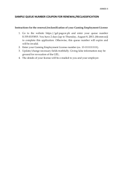
Fig. 1 shows the architecture of the presented processor.
All major modules and their Verilog module names are
shown by the figure. The processor is designed to feature
an arbitrary way superscalar pipeline, allowing up to N (N
is the number of superscalar ways, which is specified in the
Verilog .vh header file) instructions to be processed at a
time. This requires all modules to have the ability to
process n instructions in one cycle. There are mainly five
stages in this microprocessor. N instructions are firstly
fetched from ICache and memory. BTB will determine if
an instruction is a branch based on its PC. If a branch is
detected, BTB will provide its target PC and the local
predictor will predict whether the branch is taken or not. In
dispatch stage, N decoders are designed to decode the N
instructions, complete renaming and pass the relative
information to issue stage. An N-way reservation station
(RS) and a reorder buffer (ROB) receive information, issue
them out-of-order and commit them in order respectively.
In the execution stage, N function units, each with the two
types of operations including ALU and MUL, process N
instructions and get the result. If the instruction involves
memory load or store, DCache together with load queue
and store queue will receive this information and process
them out of order. Table I shows the configuration of the
core modules.
TABLE I.
SIZES OF MAJOR MODULES
RS
ROB
BTB
SQ/LQ
PRF
RAT
DCache
ICache
16
32
64
8
64
32
32
32
IV.
FEATURE IMPLEMENTATION
This section discusses the details of implementation of
each feature stage by stage. There are some modules that
do not belong to a single stage. For those modules, they
are discussed in a certain stage, because they have strong
relationship with one or more key modules in that stage.
A. Fetch Stage
The fetch stage reads in the instructions from the
ICache. Each cycle it fetches up to N instructions from the
ICache and sends the instructions along with the valid
signal to IF/ID register. The valid number of instructions is
the minimum among the valid numbers of instructions
from the ICache along with reorder buffer 's (ROB) and
reservation station's (RS) available entries. Next PC (NPC)
is determined by the current PC, valid number of
instructions, the branch predictor, BTB, and the
misprediction signal. In case there is a misprediction
resolved, NPC will be determined by the correct target PC
from ROB. If there is no misprediction, NPC will be
predicted target PC if there is a branch. Otherwise, NPC
will be PC plus valid number of instructions.
Instruction Cache (ICache)
Instruction cache is designed to be four-way associative
and blocking. Every cycle instruction cache receives up to
N requests. In case there is no cache miss, it will send
requested number of instructions to fetch stage. When
there is a miss, the program stops reading instructions in,
stalls and waits until the data is found in memory. Due to
the limitation of memory, instruction cache can only get
two instructions from memory per cycle.
The main controller in instruction cache is request
queue. Fig. 2 shows the working scheme of the request
queue. If a request is a hit, data is directly fetched from
ICache.In case a request got missed in cache memory,
request queue will take in this request. Request queue will
then send one request to memory per cycle, together with
the address information of this specific instruction and
2
register map table, the physical register files, the free list,
and the reorder buffer. An architectural register is mapped
to a new physical register taken from the free list whenever
the architectural register is the destination of an instruction.
The new physical register is marked not free until the
instruction is committed and it will be returned to the free
list. The instructions are committed in order by ROB.
Physical Register Files (PRF)
Fig. 2 Illustration of Request Queue Working Scheme for ICache
the memory will start to look for that instruction. A request
entry will be evicted when the data is found and given to
fetch stage. Every cycle memory will provide three kinds
of information to request queue: data, response and tag.
Tag is matched with data, meaning that the instruction with
this tag should take the data. Memory will also give a
response to whatever instruction sent by request queue.
This response is the key for a request to match a tag and
get data. The picture below is how instruction cache works.
Branch Target Buffer (BTB)
The BTB is a 64-entry direct-mapped register file to
store the previous target branch addresses. It’s indexed by
lower 6 bits (from bit 2 to bit 7) of the PC. For each BTB
entry, it stores a tag of 32 bits of instruction, and 32 bits of
target PC. The instruction in fetch stage uses its PC to
locate its own entry in BTB. If the instruction tag is not
matched, BTB will predicts as non-branch instruction, and
the output target PC and predictions from local predictor
will be not be used in fetch stage. After one branch is
committed in ROB and is mispredicted, BTB will update
the table with ROB committed PC and its target address.
Branch Predictor
A 2-level local predictor is used as the direction
predictor, which consists of branch history table (BHT)
and pattern history table (PHT). The BHT is a 16-entry
direct-mapped register file, indexed by lower 4 bits (from
bit 5 to bit 2) of the branch PC. Each entry has 4 bits
representing the PHT index. The PHT is also a 16-entry
direct-mapped register file, and each entry has 2 bits. It
outputs only 1-bit taken-or-not prediction by using the bit 1
of the 2-bit saturating counter predictor, beginning at
weakly-not-taken. When a branch is committed in ROB,
the counter in PHT is updated based on the result of the
branch and its PHT index, incrementing if taken and
decrementing if not taken. Also, the BHT is left shifted one
bit to store the result of the branch. Our direction predictor
predicts the all incoming instruction and sends back to
fetch stage, however, the BTB outputs a signal indicating
whether the instruction associated with the current PC is a
branch and controls the prediction to be handled correctly.
B. Dispatch Stage
The dispatch stage consists of N independent decoders,
each of which decodes an instruction from the IF/ID
register in each cycle. This stage handles the register
renaming, inserts the decoded instructions into ROB in
their original order and outputs signals to ID/ISS pipeline
registers. The key structures used in this stage are the
The PRF consists of 64 entries corresponding to 64
physical registers. Each entry stores the value of the
architectural register to which this physical register was
formerly mapped, a free signal to indicate whether it’s in
use or not and a valid signal to indicate whether it has
obtained the final result from CDB. It monitors the CDB
and ROB retire signals and then updates values, valid and
free signals in the entry. When a renaming request comes
from a decoder, PRF will outputs the free tag according to
the free list and this entry will remain not free until retired
in ROB. It also outputs the value of operands of the
instruction to RS. If the physical register is valid, it will
output the value stored, otherwise it will output the
physical register index. The valid bit will be transferred
into RS along with the operands' values, so that the RS will
be able to distinguish whether the incoming number is the
real value or the PRF index.
Renaming Table & Retire Renaming Table (RAT & RRAT)
Both RAT and RRAT have thirty-two entries. To
obtain values of operands, the RAT outputs the tags to the
PRF and the PRF generates outputs in the way described
above. Fig. 3shows the renaming scheme of our design.
Take a three-way superscalar machine as an example, in
each cycle, the priority selector will select three free PRF
and send them to RAT. Based on the renaming information
from the decoder, some architectural registers will be
renamed according. The physical registers that were
previously mapped to those architectural registers will then
be set free in PRF. To adapt to the superscalar, the
renaming must handle the data dependency among the
instructions that enter in the same cycle. Common concern
is that the later instructions depends on the previous ones
dispatched in the same clock cycle. To ensure that the later
ones always gets the most updated PRF index, the RAT
will check for this kind of dependency and forward the
correct PRF index internally. The RRAT is updated only
when the instruction is retired in ROB and records the
physical registers that have been committed according to
the architectural registers. Therefore, the RRAT stores the
renaming of each architectural register in actual finish
order. If misprediction happens, the RAT will copy the
whole table from the RRAT.
Fig. 3 shows an example of renaming of a 3-way
superscalar machine. At the beginning of every cycle,
decoders will send indices of architecture registers to be
renamed to RAT. In this example, 10, 18 and 29 are sent.
At the same time, a priority selector will select three free
physical registers from PRF and send their indices to RAT.
As shown by Fig. 3, 1, 57 and 62 are chosen and sent to
RAT in the example. Then architecture registers 10, 18 and
29 will be re-mapped to physical registers 3, 1, 57 and the
physical registers that were previously mapped to by those
architecture registers will be freed in PRF.
3
Fig. 3 Example of Renaming of a 3-way Superscalar Machine
Reorder Buffer (ROB)
The reorder buffer, which is responsible for holding and
retiring the instructions in order, is set to have 32 entries.
After an instruction is dispatched, the architectural and
physical index of the destination register and instruction
PC are stored in the entry pointed to by the tail pointer.
The indices of entries used to store instructions will be sent
to the reservation station as an instruction tag. For each
entry, there are two 1-bit signals indicating whether it’s a
branch or a halt respectively. For branch instruction,
signals including branch misprediction and branch target
PC are stored. Once the branch instruction is detected as
mispredicted at committing, ROB will squash the entries
behind it and commit this exception in the same clock
cycle. Tail pointer will be moved to point to the same entry
with the head pointer. The misprediction signal is also
output to pipeline for the purpose of updating predictors
and fetching target PC. Each time instructions are retired,
the head pointer will increment. When the new instructions
are added to ROB, tail pointer will increment and this entry
will be labeled invalid. Since the fetch stage has already
fetched appropriate number of instructions as described
previously, the instructions passed into ROB will fit into
the valid ROB entries. When a pointer comes to the end of
the ROB and it is to be incremented, it will move to the
beginning of the ROB automatically due to overflow. ROB
also has an executed signal to indicate whether an
instruction stored in ROB has finished execution.
C. Issue Stage
The issue stage waits for the data dependencies to be
cleared and issues the ready-to-execute instructions to
ISS/EX registers in each cycle. Our issue stage receives
instructions from the ID/ISS registers and stores the
instructions in the reservation station (RS). True
dependencies cannot be eliminated and instructions truly
depend on others have to wait in RS until all its operands
have valid value. False dependencies are eliminated by
register renaming. Structural hazards in this stage relate to
the function unit availability. If no functional unit is valid,
the issue stage will hold all the instructions.
Reservation Station (RS)
RS is a key module in the OoO processor design because
it holds the instructions until it has no data dependencies or
structural hazards. It is designed to have 32 entries. Each
entry records operation type, operands values or PRF index,
operands ready bit, destination register PRF index, ROB
index, next PC and prediction target PC for branch
instructions. Our RS contains a free-list module which
generates the free indices for holding new instructions and
updates the list after sending the instruction to execute
stage. By monitoring the common data bus (CDB), RS
changes the operands ready bit and values when receiving
signals indicating an execution or a memory load is done.
The computed/loaded value can be directly forwarded to
execution in the same cycle. Such forwarding can improve
the CPI by reducing the waiting time of instructions in the
RS. As shown by Fig. 4, a dependency chain consisting of
Instruction A, B, and C enters the RS in the same cycle.
Among them, B is dependent on A and C is dependent on
B. In our design, RS selects Instruction A in Cycle 2 and
Instruction A is executed in Cycle 3. RS then selects
Instruction B in Cycle 3 and forwards execution result as
B’s operands, allowing B to be executed in Cycle 4.
Similarly, Instruction C is selected at the same time B
completes execution in Cycle 4 and finishes execution in
Cycle 5.
Fig. 4 Example of Data Forwarding of a 3-way Superscalar Machine
For N sets of function units in the execute stage, each
containing an ALU and a multiplier (MULT), two priority
selectors will select N ALU operations and N
multiplication in each cycle. Each set of ALU operation
and multiplication from RS is directly mapped to the
function unit in execute stage accordingly. We will send
ALU and/or multiplication instructions to the execute
stage only if the corresponding function unit is valid.
Between ALU operations and multiplications, we select
multiplications
prior
to ALU operations because
multiplications take more cycles to execute. The RS
outputs all the indicators in one entry into the execute
stage and cleans this entry after sending. Fig. 5 shows an
example of the selection scheme of RS for three-way
superscalar machine. At the beginning of a certain cycle,
the operation type and valid status of each entry of RS is
shown by Fig. 5. The priority selector for ALU operation
then will select 3 valid ALU operations. Because there are
only two valid multiplications, the other priority selector
will only select two and leave its third entry invalid. After
selection, the selector will issue instructions following the
order that multiplications first and ALU operations after.
Since the first way have both ALU function unit and
multiplier available and both ALU operation and
multiplication valid, it will send the multiplication into the
execution stage. The second way also has both ALU
operation and multiplication valid, but its corresponding
multiplier is not ready, so ALU operation is sent out on
this way. On the 3rd way, even though that both ALU
function unit and multiplier are available, ALU operation
is sent out since the priority selector for multiplication
does not have a valid instruction on this way.
4
register of stores and loads. If there is a previous
dependent store and the address and value of this store in
known, store queue will directly forward data to load
queue and send a ready signal. Load queue will then load
the data to PRF. If there is no previous dependent store
found in store queue, store queue will still send a high
ready signal but without data. Load queue will then send
load request to data cache. After load queue got value
from data cache, it will send the value to PRF and tell
ROB this load instruction has completed. Also, the
corresponding entries in load queue will be evicted.
Store Queue
Fig. 5 Illustration of RS Selection Scheme for a 3-way Superscalar
Machine
D. Execute Stage
The execute stage carries out the instruction from the
ISS/EX registers with n sets of function unit. This stage is
purely combinational and it always executes the current
instructions regardless whether they are valid or not. In
case a current instruction is invalid, an invalid signal will
become true and will be sent to other related modules
through CDB. Each function unit contains one ALU and
one multiplier. All the function units output the results to
CDB. The ALU is non-clocked, which means that any
instruction fed into an ALU will be finished within the
same cycle. The multiplication module is pipelined with 4
stages and takes 4 cycles to finish. Because the CDB is
shared by the ALU and multiplier, in the cycle when a
multiplier finishes its computation, its corresponding ALU
cannot process any valid instruction to avoid structural
hazard. In other cycles, when a multiplier is executing, the
ALU on the same can still take in new instructions.
E. Memory Stage
The memory stage deals with load and store
instructions passed through the pipeline. In order to
improve the efficiency of communication with memory,
DCache, load queue and store queue are designed
respectfully.
Load Queue
Load queue handles load instructions and it can take at
most N instruction per cycle. Its size is subject to change
according to different ways of superscalar. Once a load
instruction has been decoded in dispatch stage, load queue
gets its information from ID/ISS register. If a load
instruction loads data from the same address previous
store instruction has stored the data in, there is a
dependency, which may cause mistake and reduction in
performance. In order to solve this problem, once the
destination register of a load instruction is valid, the
information of this load is sent to store queue to see
whether there has been a dependent previous store, which
is realized by comparing the ROB index and destination
Store queue handles store instructions and it can take at
most N instructions per cycle. Its size is also subject to
change according to different ways of superscalar. Once a
store instruction has been decoded in dispatch stage, store
queue gets its information from ID/ISS register. Store
queue will communicate with DCache, which will be
discussed later. When a load is sent to store queue to check
dependency, store queue is traversed and gives back
relative information. Because if there is a misprediction
before the store, memory cannot recover from it, entries in
store queue will only be cleared when the store instructions
saved in these entries are committed in ROB.
Data cache (DCache)
Data cache is designed to be four-way associative and
non-blocking. It takes read or write requests directly from
load queue and store queue. Each cycle, data cache takes
at most N loads and N stores and output at most N lines
for loads response. Data cache is mainly composed of
cache memory, action queue and request queue.
Fig. 6 shows the working scheme of DCache. In order
to achieve non-blocking, an action queue is built to hold
the previous missed load requests. It is filled when new
load requests come in and get a miss in data cache, and
spilled when previous unresolved load requests has been
resolved. Request queue is responsible for the
communication with memory. When a load request gets
missed in cache memory and there are no other load
requests with same address in request queue, request
queue will take in this new load request. When a store
request gets missed in cache memory, if there is a store
request with same address in request queue, the data in old
request will be updated to this new value. If there is no
store requests with same address in request queue, request
queue will take in this new store request.
Only one request can be sent to memory per cycle and
while data cache is sending request to memory, instruction
cache should not send request. After a request has been
sent, request queue will store the response from memory.
For each cycle, if the memory tag is not zero, and matches
one of the response stored in request queue, memory data
will be taken in and written in cache memory. Once a
request has been resolved in request queue, the address
and data will be broadcasted to all entries in action queue.
In the next clock cycles, if one or more load requests from
load queue get missed, an empty slot can be found to
return the data of solved load request in action queue.
5
algorithm and 4-way associative was considered to be the
solution. 4-way associative cache worked with 20ns
reduction in clock period and performed little impact on
hit/miss rate for instruction cache. Pseudo LRU algorithm
showed little reduction in clock period so true LRU
remained unchanged.
C. Reservation Station Design
One-way RS v.s. N-way RS
Fig. 6 Working Scheme of DCache
V.
TEST & ANALYSIS
This section covers the analysis of the design and
performance tests of the design.
A. Choice of Predictor
Local predictor scheme was chosen after compared to
Gshare predictor, which uses the part of branch PC to XOR
branch history register and then looks into the pattern
history table to find the prediction result. Local predictor
allows the processor to better predict the pattern of branch
by remembering the most recent decision of branch based
on specific reference indexed by branch PC. The
performance of local predictor is better than Gshare
predictor because the use of global history register might
outputs wrong information if one or two branches are
unresolved. This happens due to the resolution of branches
in later stage. So if two branches share the same index PC
of predictor, the later one won’t get the results updated by
the previous one and will be likely to be wrong. Therefore,
local predictor avoids this problem and now only tight
branches may have faults. Local predictor also simple to
implement compared to more advanced alternatives such
as tournament predictor.
Table I shows the hit rate of different configurations of
BTB, PHT and BHT. As shown by Table II, there is a
performance threshold regarding BTB size between 16 and
32. In addition, hit rate is positively related with the sizes
of BTB, PHT and BHT. Since none of these modules is on
the critical path in the processor, there are all of maximum
sizes in the final design.
TABLE II.
HIT RATE OF LOCAL PREDICTOR
BTB Size
PHT Size
BHT Size
Hit Rate
64
16
16
81%
32
16
16
80%
16
16
16
78%
64
8
16
71%
B. Cache Design
At the beginning, fully associative with true LRU
algorithm instruction cache was designed. During
synthesizing, the clock period was found to be more than
25ns for instruction cache. The analysis showed that the
traversal through all 32 entries to find the appropriate
position for new data was the critical path. Pseudo LRU
In the final design, one RS is implemented which is
able to receive and send multiple instructions in one cycle.
The advantage of such implementation is that the
information regarding RS can be unified. For example, the
fetch stage can read in a single value of RS size to
determine the number of instructions to fetch.
In previous designs, a multi-RS implementation was
attempted but denied. The multi-RS implementation aims
to simplify the output logic where each RS is mapped to a
fixed set of function units (which is applied in our current
single-RS design.) However, this design was unable to
inform fetch stage about its availability. Without knowing
how many instructions the RS can store, fetching became
problematic and might require recovery in later stages.
Therefore, the multi-RS design was discarded.
Selection Logic
Another possible selection (and once implemented)
logic in RS can be demonstrated in Fig. 7, where no
forwarding logic is implemented. Dependent instructions
such as Instruction B are no longer able to be selected in
Cycle 3. The same dependency chain will require 2 more
cycles before Instruction C before it completes execution.
Fig. 7 Example of an Alternative RS Selection Scheme of a 3-way
Superscalar Machine
This selection logic was competitive with respect to the
logic applied in the final design because it eliminates all
forwarding and greatly reduces the clock period of the
issue stage. However, by implementing this logic in the
three-way superscalar design, the clock period was not
improved because issue stage was not included in the
critical path. Thus, the forwarding logic was chosen in our
three-way superscalar design. As for superscalar designs
with the number of scalar greater than three, the
forwarding logic became the critical path in the design.
This change of delay was caused by the increase of the
sizes of other modules such as LSQ, which required more
time to obtain the results.
A third implementation for selection logic was
proposed but not implemented. Stark, a researcher from
Intel Corporation introduced this logic in his paper. The
logic applies dynamic scheduling technique, which allows
RS to speculate the execution order of the instructions
without having its operand values ready [1]. To explain
6
this logic, we use the same example with Inst A, B, and C,
as shown in Fig. 8. In the dynamic scheduling scheme,
Inst A broadcasts its PRF entry number at the same time it
is selected, which also wakes up Inst B. Inst B is selected
to be executed in Cycle 3 and wakes up Inst C. Without
having the result ready, Inst B takes another cycle to read
the execution result (Cycle 4.) By applying the dynamic
scheduling scheme, the forwarding logic can be simplified,
thus reducing the delay. In addition, the number of cycles
used to complete execution decreases.
Fig. 10 RS after first cycle
Fig. 8 Dynamic Scheduling Scheme in RS
However, the dynamic scheduling scheme introduced
complicated recovery logic and required intensive
modification to the pipeline, which eventually enforced us
to give up this scheme.
D. Out-of-order Implementation
This section will demonstrate the out-of-order
algorithm in our design with an assembly code segment.
The segment listed below is taken from one of the
instructor test cases.
mulq
addq
srl
srl
srl
$r12,$r2,$r1
$r1,$r3,$r1
$r10,32,$r10
$r11,32,$r11
$r12,32,$r12
Fig. 11 RS after multiplier finishes execution
finishes execution in the next cycle. Thus, we finish
executing the code segment with the out-of-order
algorithm.
E. Test Results
In our design, the number of scalars and sizes of
modules can be specified at will. In order to find the best
combination of module sizes and scalar numbers, a series
of testbenches were performed. In the following four
tables (Table III, IV, V, and VI,) a collection of sizes of
core modules (RS, ROB, PRF, LQ, and SQ) with respect
to the number of scalars are presented. The following
figure (Fig. 12) demonstrates the test result in term of CPI.
TABLE III.
DIFFERENT CONFIGURATIONS OF 2-WAY SUPERSCALAR
MACHINE
In this segment, addq is dependent on the result of mulq
(both architectural register 1.) At the same time, all srl
instructions are independent of preceding instructions.
Provided that all five instructions are stored in the RS of a
three-way superscalar machine, as shown in Fig. 9, the
selection logic will first select mulq and two srl
instructions to send to execution. In this example, assume
that RS selects the first two srl instructions.
2-way #1
2-way #2
2-way #3
RS
32
16
16
ROB
32
32
16
PRF
64
64
64
LQ
8
8
8
SQ
8
8
8
TABLE IV.
DIFFERENT CONFIGURATIONS OF 3-WAY SUPERSCALAR
MACHINE
3-way #1
3-way #2
3-way #3
RS
16
32
16
ROB
32
32
32
PRF
64
64
64
LQ
8
8
16
SQ
8
8
16
Fig. 9 Initial state of instructions in RS
In the next cycle, only two instructions are in the RS, as
shown in Fig. 10. The selection logic will select srl
because addq has one operand not ready (depending on
the result of previous mulq.) Therefore, only srl is sent to
execution in the next cycle.
After three cycles, multiplier will finish execution and
broadcast the result. The addq instruction in the RS will
receive the value and change its ready bit to 1, as shown in
Fig. 11. Then the selection logic selects this addq and
7
TABLE V.
DIFFERENT CONFIGURATIONS OF 4-WAY SUPERSCALAR MACHINE
4-way #1
4-way #2
4-way #3
4-way #4
4-way #5
4-way #6
RS
64
32
64
32
32
16
ROB
64
32
32
64
64
32
PRF
96
64
64
96
96
64
LQ
16
16
16
16
8
16
SQ
16
16
16
16
8
16
TABLE VI.
DIFFERENT CONFIGURATIONS OF 5-WAY SUPERSCALAR MACHINE
5-way #1
5-way #2
5-way #3
5-way #4
RS
64
64
64
128
ROB
64
64
128
64
PRF
96
96
160
96
LQ
16
24
16
16
SQ
16
24
16
16
Fig. 12 Normalized CPI vs. N-Way Superscalar with Different Configurations
All the module sizes were determined through our
designing and debugging process. The design was
implemented based on a 3-way superscalar machine.
During the design, we found that a 32-entry ROB seldom
got full, while a 16-entry ROB was frequently filled. Note
that the CPI was measured for brief analyze at a clock
period of 12.5 ns, which was the clock period of 3-way #1.
Change of memory latency will be considered later.
In Fig. 12, several combinations of module sizes
provided promising CPI. By examining the results closely,
some conclusions were made:
1.
Generally, the CPI decreases as the scalar number
goes up. This result meets our expectation because
higher scalar number allows more instructions to be
executed in parallel. However, none of 5-way
8
superscalars shows improvement compared to 4-way
superscalars. Considering the test sizes (lines of
instructions in a test case,) this situation may result
from insufficient number of instructions, i.e., the
tests are not large enough to fully utilize the
hardware resources provided by 5-way superscalars.
By comparing module sizes among superscalars with
the same scalar count, larger ROB size is found to be
the primary factor for better CPI. The increase of
ROB size provides the pipeline a bigger instruction
window, allowing the processor to execute more
instructions before committing. Since scalar count
rises, more instructions can be fetched in one cycle,
ROB size should also increase.
The size of LQ/SQ becomes another restriction when
the scalar count and ROB size rises. We believe that
larger ROB size brings more load and stores into the
instruction window. In our design, if LQ or SQ is
filled, the pipeline should be stalled to wait for
memory accesses. Therefore, LSQ size should also
increase along with ROB size.
2.
3.
To determine the final configuration of our design,
specifically the scalar count and module sizes, clock
period must be tested. Among the configuration listed
above, 2-way #1, 3-way #1, 2, and 3, 4-way #1 and 4 were
chosen as candidates. For each configuration, the design
was synthesized to test the actual clock period. For
synthesis setup, we specified map effort to “medium”
in .tcl file. The clock period is recorded in Table VII.
TABLE VII.
clk
2-way
#1
12 ns
CLOCK PERIOD OF DIFFERENT CONFIGURATIONS
3-way
#1
12.5 ns
3-way
#2
18 ns
3-way
#3
20 ns
4-way
#1
22 ns
4-way
#4
22 ns
data from Reg A in the RS and the value of Reg A is
computed in the same cycle, the forwarding logic will
detect PRF entry index (tag) broadcasted on the CDB and
allow this instruction to be sent to execution in this cycle.
Without forwarding, the same instruction has to wait in
the RS for its ready bits to be updated, which requires
another cycle to be executed.
However, the forwarding in RS and LSQ introduces
large delay to the pipeline design. Such delay is not
exposed in the final design as the critical path exists
between ICache and fetching stage. As for the other
design we synthesized in the previous section, RS
appeared in every critical path in the post-synthesis report.
To prove the relation between forwarding logic and delay,
the forwarding logic was cancelled in the RS for
configuration 3-way #2. The new clock period fell to 12.5
ns, the same as 3-way #1 configuration, while the
normalized CPI rises to 1.06 which did not give a better
performance. This result clearly stated that forwarding in
the RS affected clock period. Similar result appeared after
we cancelled the forwarding in LSQ, which resulted in
CPI increase and slightly worse overall performance. In
the sense of higher scalar counts, we recommend disabling
all forwarding logic to achieve better clock period. If
refined pipeline structure can be applied, we believe our
pipeline can perform better with scalar number greater
than 4.
VI. CONTRIBUTION
Table IX shows the contribution of each group member.
Our group member averagely undertook the module
implementation. In addition, Jingyuan Sun and Yuanlang
Song spent more effort in testing the high-level design.
TABLE IX.
CONTRIBUTION OF EACH GROUP MEMBER
Responsible Work
Testbenches were re-run with post-synthesized clock
period to calibrate the CPI (normalized.) The result is
shown in Table VIII, together with the product of clock
and CPI with respect to each configuration. The product
can be used to represent Tcpu level for each configuration.
TABLE VIII.
TCPU OF DIFFERENT CONFIGURATIONS
Clk
2-way
#1
12 ns
CPI
1.11
3-way
#1
12.5
ns
1
Prod
13.32
12.5
3-way
#2
18 ns
3-way
#3
20 ns
4-way
#1
22 ns
4-way
#4
22 ns
0.972
0.90
0.826
0.826
17.50
18
18.17
18.17
With the product of clock period and calibrated CPI,
configuration 3-way #1 was chosen as our final design.
F. Forwarding and Performance
In our design, data forwarding logic was intensively
implemented to shrink CPI. The forwarding was applied
in RS, PRF, and LSQ. By forwarding the execution results,
we do not need an extra cycle for instructions to read the
register values. For example, if an instruction requires
Chuyi Jiang
Percentage
Contribution
19%
Di Hu
Id_stage, Local_pred,
if_stage, RAT/RRAT
BTB, Ex_stage
Jingyuan Sun
RS, ROB
23%
Yongyi Lu
If_stage,PRF, if_stage
19%
Yuanlang Song
LQ/SQ, ICache, Dcache
20%
19%
VII. CONCLUSION
This report presents a R10K pipelined processor with
arbitrary-way superscalar pipeline, local branch predictor,
branch target buffer, load-store-queue, four-way
associative non-blocking data cache and instruction cache,
and advance data forwarding. The design significantly
reduces the CPI and keeps the clock period at a reasonable
level. With the unified algorithm for various design
configurations in our Verilog implementation, our design
can be fully customized in terms of scalar count and every
module’s size. By securing the correctness and achieving
flexibility, we have successfully fulfilled the project
requirement of constructing a functional processor. Future
work may include optimizing the selection logic of RS,
9
improving the forwarding scheme, and designing better
branch prediction units.
VIII. Acknowledgement
This work was finished with the help from Prof. Mark
Brehob, and GSIs Jonathan Beaumont, William
Cunningham and Jason Shintani. We would like to thank
them for their generous help and patient guidance.
REFERENCE
[1] Stark, J.; Brown, M.D.; Patt, Y.N., "On pipelining dynamic
instruction scheduling logic," Microarchitecture, 2000. MICRO-33.
Proceedings. 33rd Annual IEEE/ACM International Symposium on , vol.,
no., pp.57,66, 2000.
10
APPENDIX A Table of Hit Rate for Each Test Program of Machine Configured in 3-way #1
11
APPENDIX B Table of CPI for Each Test Program of Machine with Different Configurations
12


© Copyright 2026