
Secure and Efficient Initialization and Authentication Protocols for
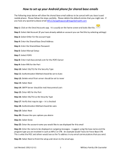
Secure and Efficient Initialization
and Authentication Protocols for SHIELD
Chenglu Jin and Marten van Dijk
University of Connecticut
[email protected], [email protected]
March 4, 2015
Abstract
With the globalization of semiconductor production, out-sourcing IC fabrication has become
a trend in various aspects. This, however, introduces serious threats from the entire untrusted
supply chain. To combat these threats, DARPA (Defense Advanced Research Projects Agency)
proposed the SHIELD (Supply Chain Hardware Integrity for Electronics Defense) program to
design a secure hardware root-of-trust, called dielet, to be inserted into the host package of
legitimately produced ICs. Dielets are RF powered and communicate with the outside world
through their RF antennas. They have sensors which allow them to passively (without the need
for power) record malicious events which can later be read out during an authentication protocol
between the dielet and server with a smartphone as intermediary.
In this paper, we propose to use AES counter mode encryption (as opposed to DARPA’s
suggested plain AES encryption) as a basis for the authentication process. We show that this
leads to several advantages: (1) resistance to a “try-and-check” attack which in case of DARPA’s
authentication protocol nullifies the effectiveness of one of SHIELD’s main goals (that of being
able to detect and trace adversarial activities with significant probability), (2) immunity against
differential power analysis and differential fault analysis for free, (3) a 2× speed up of the
authentication phase by halving the the number of communication rounds with the server, and
(4) a significant reduction of the power consumption of the dielet by halving the number of
needed AES encryptions and by a 4× reduction of the number of transmitted bits.
Each dielet needs to go through an initialization phase during which the manufacturer sets a
serial ID and cryptographic key. In this paper we propose the first efficient and secure initialization protocol where dielets generate their own serial ID and key by using a true random number
generator (TRNG). Finally, the area overhead of our authentication and initialization protocols
is only 64-bit NVM, one 8-bit counter and a TRNG based on a single SRAM-cell together with
corresponding control logic.
Contents
1 Introduction
1.1 Contributions . . . . . . . . . . . . . . . . . . . . . . . . . . . . . . . . . . . . . . . .
1.1.1 Performance Benefits . . . . . . . . . . . . . . . . . . . . . . . . . . . . . . . .
1.1.2 Security Benefits . . . . . . . . . . . . . . . . . . . . . . . . . . . . . . . . . .
1
2
4
4
5
1.1.3 Area Overhead . . . . . . . . . . . . . . . . . . . . . . . . . . . . . . . . . . .
Organization . . . . . . . . . . . . . . . . . . . . . . . . . . . . . . . . . . . . . . . .
5
5
2 Supply Chain Security
2.1 IC Supply Chain Vulnerabilities . . . . . . . . . . . . . . . . . . . . . . . . . . . . . .
2.2 Recent Detection/Avoidance Methods . . . . . . . . . . . . . . . . . . . . . . . . . .
2.3 Trust Model for SHIELD . . . . . . . . . . . . . . . . . . . . . . . . . . . . . . . . .
6
6
6
7
1.2
3 Authentication Protocol
3.1 Our Proposal . . . . . . . . . . . . . . . . . . . . . . . . . . . . .
3.2 Read-out Mode . . . . . . . . . . . . . . . . . . . . . . . . . . . .
3.3 Authentication Mode . . . . . . . . . . . . . . . . . . . . . . . . .
3.4 Security Analysis . . . . . . . . . . . . . . . . . . . . . . . . . . .
3.4.1 Probability of Successful Impersonation Attack . . . . . .
3.4.2 Probabilistic vs Deterministic Encryption . . . . . . . . .
3.4.3 Detection of Number of Dielet Readouts . . . . . . . . . .
3.4.4 Try-and-Check Attacks . . . . . . . . . . . . . . . . . . .
3.4.5 Resistance against Non-Invasive Attacks . . . . . . . . . .
3.4.6 Resistance against Invasive and Semi-Invasive Attacks . .
3.5 Performance Improvement . . . . . . . . . . . . . . . . . . . . . .
3.6 Other Design Considerations . . . . . . . . . . . . . . . . . . . .
3.6.1 AES CTR Mode vs One-Time Pad . . . . . . . . . . . . .
3.6.2 AES CTR Mode vs Stream Cipher . . . . . . . . . . . . .
3.6.3 Integration with RFID tags in Supply Chain Management
.
.
.
.
.
.
.
.
.
.
.
.
.
.
.
.
.
.
.
.
.
.
.
.
.
.
.
.
.
.
.
.
.
.
.
.
.
.
.
.
.
.
.
.
.
.
.
.
.
.
.
.
.
.
.
.
.
.
.
.
.
.
.
.
.
.
.
.
.
.
.
.
.
.
.
.
.
.
.
.
.
.
.
.
.
.
.
.
.
.
.
.
.
.
.
.
.
.
.
.
.
.
.
.
.
.
.
.
.
.
.
.
.
.
.
.
.
.
.
.
.
.
.
.
.
.
.
.
.
.
.
.
.
.
.
.
.
.
.
.
.
.
.
.
.
.
.
.
.
.
.
.
.
.
.
.
.
.
.
.
.
.
.
.
.
8
8
9
9
11
11
11
11
12
12
13
13
14
14
14
14
4 Initialization Protocol
4.1 True Random Number Generator
4.2 Initialization Protocol . . . . . .
4.3 Serial ID Collision . . . . . . . .
4.4 Performance . . . . . . . . . . . .
.
.
.
.
.
.
.
.
.
.
.
.
.
.
.
.
.
.
.
.
.
.
.
.
.
.
.
.
.
.
.
.
.
.
.
.
.
.
.
.
.
.
.
.
15
15
16
16
17
.
.
.
.
.
.
.
.
.
.
.
.
.
.
.
.
.
.
.
.
.
.
.
.
.
.
.
.
.
.
.
.
.
.
.
.
.
.
.
.
.
.
.
.
.
.
.
.
.
.
.
.
.
.
.
.
.
.
.
.
.
.
.
.
.
.
.
.
.
.
.
.
5 Area Overhead
17
6 Conclusion
17
1
Introduction
Outsourcing IC (Integrated Circuit) fabrication has become mainstream in IC design, fabrication,
testing and packaging. Even though outsourcing to a trustworthy manufacturing facility for legitimate IC fabrication and assembly is assumed by default, legitimately produced ICs still need to
pass through the remainder of a supply chain which is not in one’s own control and can therefore
not be trusted. This opens a whole new range of serious threats including compromise of IP (Intellectual Property) Privacy, IC Overbuilding, Reverse Engineering, and Counterfeit ICs. Due to
these attacks, semiconductor industry loses 4 billion dollars annually [1].
In order to prevent or detect such attacks one would ideally want to have an additional point
of trust within the supply chain such that somehow tamper-evidence can be added to legitimately
2
manufactured ICs. A first approach is to be completely in control of IC packaging so that ICs will be
equipped with trusted packages which are smart in that they are into some extent tamper-evident.
In other words, if tampering happens, then the package will gather irreversible evidence of the
tampering. This evidence can be seen or “read-out” later to allow verification of the authenticity
and integrity of the IC inside the package.
DARPA (Defense Advanced Research Projects Agency) takes this approach to a new level:
Their SHIELD (Supply Chain Hardware Integrity for Electronics Defense) program proposes to
embed/insert an ineradicable hardware root-of-trust, called dielet, into the host package of every
legitimately produced IC. The dielet is intelligent in that it is able to passively sense and record
malicious behavior (in the form of unexpected exposure to light, vibration, etc.) and is able to
be read-out later to report any recorded tampering evidence. SHIELD goes beyond the simple
first approach described above: Not the IC packaging process itself needs to be designed to offer
tamper-evidence, one only needs to make sure that a process of inserting dielets into host packages
of legitimately produced ICs is in place. This process of dielet insertion must be part of the trusted
IC assembly otherwise any (malicious) IC can be linked/bound to a valid dielet and later on pass
identification and authentication as if the IC can be trusted to be what it claims to be through the
dielet.
Notice that the proposed dielet technology transforms any host package into a tamper-evident
one. Besides the smaller Trusted Computing Base (TCB) in the form of trusting the dielets and
trusting the bond (= host package) between ICs and dielets (rather than trusting a larger overall
tamper-evident packaging), this is another main advantage of SHIELD: The SHIELD technology is
a sort of labeling technology which applies to already existing IC manufacturing and corresponding
supply chains.
The main design features of a dielet are shown in Figure1, the entire authentication system
contains three parts: a dielet inserted in the package of the host chip, a smartphone and a secure
remote server. The remote server stores the information for identification and authentication, such
as serial ID and cryptographic key for each dielet. The communication between the server and
the dielet requires an inexpensive appliance to read the dielet. A smartphone with a probe as a
common appliance can be used in practice. The communication channel between the server and
the smartphone is over a wireless network and over the Internet while the dielet connects to the
smartphone via an RF (Radio Frequency) channel. Because the dielet is passively powered up
through a RF transceiver module, the dielet has to be both area and energy efficient.
The dielet provides a unique permanent identification and implements sensors that are capable
of measuring extreme temperature, light exposure, vibration, UV radiation, etc. As a consequence
of passive power supply, the sensors must be passive (e.g., light exposure can be recorded using
photo sensitive material) [2].
The dielet has an encryption engine in order to encrypt the communication between the dielet
and server (through the potentially untrusted smartphone). Some NVM (Non-volatile Memory)
is embedded in the dielet to store a cryptographic key and a serial ID. We propose to add a
hardware counter block (the top shaded block in Figure1) in NVM in order to enable AES (Advanced
Encryption Standard) [3] counter mode encryption [4]. This as we will explain will make the
authentication protocol more secure, will speed up the authentication protocol, and will reduce
the power consumption of the authentication protocol at the cost of one 8-bit counter in NVM as
additional area overhead. In particular, we introduce the “try-and-check” attack which in case of
DARPA’s authentication protocol nullifies the effectiveness of one of SHIELD’s main goals (that of
3
Dielet
RF
Transceiver
Serial
ID
Control
Logic
Key
AES
Encryption
Engine
Counter
Block
NVM
TRNG
Passive
Sensors
Host Chip
Secure Server
Smartphone
Figure 1: Authentication system of SHIELD.
being able to detect and trace adversarial activities with significant probability). We show how our
proposal prevents such attack.
Besides the authentication protocol we also need a protocol which initializes dielets with their
own unique serial IDs and cryptographic keys. We propose to add a TRNG (True Random Number
Generator) so that dielets can self-generate a serial ID and a secret key (the bottom shaded block
in Figure1).
1.1
Contributions
We introduce a new authentication and initialization protocol for SHIELD with the following advantages:
1.1.1
Performance Benefits
• We significantly reduce the dielet power consumption during authentication because of two
crucial performance improvements:
– Our proposed authentication protocol transmits only 208 bits between the dielet and
smartphone, instead of 832 bits in DARPA’s authentication protocol.
– Our proposed authentication protocol uses only one AES encryption per authentication
request as opposed to DARPA’s protocol which needs two AES encryptions per request.
4
• The speed of any authentication protocol is dominated by the relatively large network latency
between the smartphone and server. For this reason our protocol achieves a 2× speed up
compared to DARPA’s protocol by reducing two full communication rounds between the
smartphone and server in DARPA’s protocol to only one round in our protocol.
• Our proposed initialization protocol is secure and has negligible performance overhead.
1.1.2
Security Benefits
• Since DARPA’s protocol uses plain AES which offers only deterministic symmetric key encryption, ciphertexts corresponding to the same plaintext in DARPA’s protocol are linked
over time. This makes their protocol particularly vulnerable to a simple “try-and-check” attack which makes DARPA’s protocol useless with respect to one of SHIELD’s main aims: The
try-and-check attack nullifies an important role of the use of passive sensors in SHIELD in
that adversaries are able to select which counterfeited/malicious chips have an assembled host
package carrying a maliciously added dielet (taken from another legitimately produced host
package) whose sensors did not detect any tampering (i.e., did not detect the removal and
adding of the dielet from the legitimate host package to the maliciously assembled host package). So, adversaries are able to eliminate any trace or evidence of counterfeited/malicious
chips that can be detected by the authentication protocol. Our proposal on the other hand
prevents such attack, because it is based on AES in Counter Mode which is a probabilistic
encryption scheme and therefore makes all ciphertexts look random to the adversary.
• The counter of AES in Counter Mode can be used as an extra sensor which teaches the
authentication server how many times the dielet has been put into authentication mode when
the dielet is offline with respect to the server. This can be used as an indicator of suspicious
behavior.
• By setting a maximum to the allowed number of counter increments (which limits the dielet
lifetime), our protocol has immunity against (non-invasive) differential power analysis and
differential fault analysis. Even if an attacker is willing to pay the price of extracting a
serial ID and key pair, the pair can only be used up to the allowed maximum (otherwise the
authentication server will detect that its synchronized counter exceeds the maximum). This
demotivates an economically motivated adversary to extract serial ID and key pairs.
1.1.3
Area Overhead
The additional area overhead for our protocols compared to DARPA’s authentication protocol is
only 4% of the allowed area of the dielet (0.01mm2 [5]) in 32nm technology, which is very small
compared to the area needed for AES, the passive sensors, RF transceiver, etc.
1.2
Organization
Section 2 provides background on supply chain security, discusses supply chain vulnerabilities and
countermeasures, and introduces the trust model of SHIELD. Section 3 presents DARPA’s suggested
authentication protocol and describes our proposal of a secure and efficient alternative for SHIELD
together with a performance and security analysis. In particular, we introduce the try-and-check
attack. Section 4 explains our proposal of a new initialization protocol together with a performance
5
and security analysis. Section 5 analyses the area overhead of our protocols and section 6 concludes
the paper.
2
2.1
Supply Chain Security
IC Supply Chain Vulnerabilities
Supply Chain Security has recently gained significant interest in the hardware security community [6, 7]. [7] presents a detailed taxonomy of supply chain vulnerabilities, where supply chain
vulnerabilities are classified into seven categories, as shown in Figure2. (1) Cloned: Cloning is a
common threat for IC design. Adversaries want to reduce the cost of design by cloning the design
of others and produce their own chips illegally. This may happen during the design phase (copying
the design files illegally) or distribution phase (reverse engineering the chip to obtain the design of
a chip). (2) Tampered: Tampering with a chip is more commonly known as adding a Hardware
Trojan, a research area that gained lots of interest in recent years [8]. Each phase of the supply
chain is vulnerable to an adversary inserting a Hardware Trojan in order to initiate stealthy and
malicious or destructive behaviors. (3) Overproduced: Since the globalization of semiconductor
business, fabrication and assembly have largely shifted to foundry/assembly facilities, these facilities are capable of producing more chips than those promised by a contract or agreement. Untrusted
facilities will illegally sell overproduced chips for extra profit. (4) Defective: Defective chips fail
to correctly respond to at least one test vector. Yet, a defective chip may be sold as a functional
chip on open markets by an irresponsible manufacturer who knows that the defect can only be excited in a corner case. (5) Recycled: After the lifetime of an electronic component, the component
should be recycled properly. However, many recycled ICs are sold as new ICs after repackaging
and remarking. (6) Remarked: In remarking, the adversaries remove the old marking on the chip
and create a new coating for it with the aim to sell it with a higher specification. (7) Forged
Documentation: Forged documentation includes a revision history of a component, certifications
of compliance for some standards, etc.
2.2
Recent Detection/Avoidance Methods
Recently, researchers in academia and industry have proposed many counterfeit detection/ avoidance methods. Generally, these methods assign an ID to each chip and verify chips by checking
these IDs. For example, silicon PUF (Physically Unclonable Function) technology [9, 10] can be
used for IC identification and authentication since PUFs exploit the randomness of process variation during the fabrication phase to generate an unique fingerprint for each chip. It is impossible
for an attacker to duplicate the PUF design with the exactly same process variation to regenerate
the same chip ID. This is used to target remarked, overproduced, and cloned chips in the supply
chain [7].
Another proposed counter measure is Hardware Metering, which is a set of security protocols
that enables design houses to achieve post-fabrication control of the fabricated IC. Usually hardware
metering methods allow the designer to lock each chip through the fabrication, which means the
chips are not functional, and these locked chips can be unlocked only by the designers [11]. This
prevents overproducing and cloning. In similar style, Secure Split Testing allows designers to protect
and meter their design after fabrication by introducing the designs into a testing phase to prevent
defective chips from entering the open market [12].
6
Cloned
Tampered
Design
Chip
Overproduced
Defective
Tampered
Overproduced
Defective
Tampered
Fabrication
Assembly
All counterfeit
types
Recycled
Remarked
Defective
Tampered
Distribution
Lifetime
Recycled
Remarked
Defective
Tampered
End of Life/
Recycling
Key &
Serial ID
Design
Dielet
Fabrication
Chips can be verified anywhere in between
Server
Figure 2: IC supply chain vulnerabilities and trust model for SHIELD. Dielet design, fabrication,
insertion in IC host package, and initialization are each trusted. In addition either IC design,
fabrication, and assembly must be trusted, or post-silicon Hardware Trojan detection and VLSI
testing schemes must be employed.
Split Manufacturing is another method to prevent untrusted foundries from overproducing chips.
The designers split the layout of a chip into front-end-of-line and back-end-of-line layers, and
fabricate these two layers in two different untrusted foundries (who are assumed not to collaborate).
Next, the design house just needs a low-end trusted manufacturing facility to assembly these two
layers [13].
Finally, lightweight aging sensors can be embedded into chips to detect recycled chips [14].
Since these sensors are capable of recording the usage time of a chip, the verifier can easily figure
out for how long this chip has been used.
2.3
Trust Model for SHIELD
The trust model for SHIELD is illustrated in Figure2. The supply chain above the dashed line is the
original supply chain for IC design, and the one below is added by SHIELD to produce trustworthy
dielets which are inserted in the host packages of legitimately produced ICs. The design, fabrication,
insertion and initialization of dielets need to be trusted (white blocks in Figure2).
Dielets allow the identity and authenticity of chips to be verified at any stage in the supply
chain after the insertion process. Notice that even if the manufacturing facility cannot be trusted,
overproduction can now be prevented by controlling and recording the number of used dielets.
Concluding, SHIELD alone without assuming a trustworthy manufacturing facility for ICs has a
near 100% coverage of all vulnerabilities in the entire supply chain, except for detection of possibly
tampered and defective chips produced at the design and fabrication stages. Of course if SHIELD
is combined with some post-silicon Hardware Trojan detection [15, 16] and VLSI (Very Large Scale
Integrated circuit) testing schemes [17], all of the vulnerabilities in the whole supply chain are
covered by SHIELD without the need for assuming a trustworthy manufacturing facility for IC
design, fabrication, and assembly.
7
3
Authentication Protocol
Dielet
Smartphone
Server
(1) Send Serial ID to Serial ID
64
ID
Smartphone
(2) Forward Serial ID Serial
64
to Server
(3) Look up (serial ID, K’)
(4) Generate a random
C
256
challenge C and send
C
Authentication
back
256 (5) Forward C to
Protocol
(6) X = ENCK(C)
Dielet
(7) Y = ENCK(SS)
X&Y
(8) Upload X & Y
512
(9) Forward X & Y to
X&Y
512
Server
(10) C’ = DECK’(X)
(11) Verify C == C’?
(12) SS = DECK’(Y)
Result
(13) Check sensor status
bits SS
Figure 3: DARPA’s Authentication Protocol. SS is sensor status. There are two full communication
rounds between the smartphone and the remote server. It encrypts the challenge and sensor status
bits separately. The total transmitted bits between the dielet and the smartphone is 832 bits.
In the call for proposals for SHIELD [5], DARPA suggests the authentication protocol as depicted in Figure3. In order to verify the authenticity of the host chip, a smartphone with an
inductive or RF probe plugged into it is used to first power up the dielet and upload the serial
ID of the dielet to the server. Next, the server looks up the entry that corresponds to the serial
ID in its database. If it is an existing serial ID in the database, the server generates a random
challenge/nonce C and sends C to the dielet through the smartphone. The dielet encrypts the
challenge and the sensor status bits SS using the on-board cryptographic key K, and sends the
resulting ciphertexts X and Y back to the server. The server decrypts the ciphertext X using the
key K’ corresponding to the serial ID stored in the server’s database, and compares the result C’
with the original challenge C. If C’ matches C and the sensor status bits do not record any attacks,
then the server concludes that this chip is legitimately produced. In the last step the server replies
the authentication result to the smartphone (to avoid man-in-the-middle attacks the smart phone
and server are assumed to have their own authentic channel).
3.1
Our Proposal
As explained in the introduction, we propose to base the authentication protocol on AES counter
mode: Counter (CTR) mode [4] is a mode of operation for block ciphers: In order to produce a
ciphertext, the most recently used counter value is incremented and encrypted, and the result is
exclusive-ORed with the plaintext. We notice that the NSA (National Security Agency) Suite B
8
Cryptography approved AES in CTR mode and that AES counter mode is also recommended by
NIST (National Institute of Standards and Technology) [18]. E.g., counter mode encryption is used
in the IPsec Internet Draft [19] and ATM Security Specification [20].
Before we explain our authentication protocol, we notice that counter mode encryption in
dielets has a potential vulnerability in that it can be exploited in a denial-of-service (DoS) attack:
An attacker can power up a batch of dielets, causing each dielet to irreversibly increase its counter.
This may force counters to run out of range, i.e., the server will not be able to synchronize its
own copies of the counter values and will therefore reject future legitimate attempts of dielets to
authenticate themselves. In order to prevent this DoS attack, we add a read-out mode before the
authentication mode. Only after the dielet confirms (by verifying a challenge) that the smartphone
attempts to transmit messages with the dielet, the dielet will enter an authentication mode during
which its counter is incremented. We notice that DARPA’s protocol does not need this extra
read-out mode because it uses plain AES encryption (without irreversible counters).
3.2
Read-out Mode
Initially, during read-out mode, the dielet waits to be powered up. As soon as it powers up, the
dielet checks whether the counter value CB is larger than 1 and less than a maximum value M AX.
If the check fails, then either the dielet has not yet been fully initialized (CB equals 0 or 1) and
should enter self-generation and initialization mode, or the counter has reached a prefixed maximum
number M AX of times the dielet is allowed to enter authentication mode during which its sensor
status SS is read-out and communicated to the server. Checking CB being less than M AX limits
the number of encryptions on the dielet and also prevents the counter to roll-over and repeat itself.
If the check passes, then the dielet will proceed to the next step (15). See Figure4 (c), the
dielet transmits its serial ID to the smartphone via the read-out unit. The smartphone truncates
the serial ID to L bits and sends the truncated serial ID back to the dielet. The dielet verifies the
reply from the smartphone which, if correct (i.e., it corresponds to the dielet’s serial ID), puts itself
into authentication mode. Because the smartphone has to send the truncated L-bit serial ID back
to confirm the communication request, DoS attacks against a batch of dielets simultaneously are
prevented (since each dielet verifies its own unique L-bit truncated serial ID).
3.3
Authentication Mode
Figure4 (d) shows the sequence of operations in authentication mode. After the dielet enters
authentication mode, the on-board cryptographic key K and the hardware counter block CB are
retrieved from NVM to compute X = AESK (CB). At the same time, the counter block CB is
incremented. In step (19) the dielet takes the first N bits of X and exclusive-ORs these with the
S-bit status bits (SS) from the dielet’s passive sensors padded with zeroes up to N bits (N 256).
The padded zeros are used for authentication as explained below. The result after the exclusiveOR is an N -bit “verification message” V which is transmitted to the smartphone. After the above
steps, the dielet returns to read-out mode, and waits for a next authentication request in step (14).
The smartphone forwards V to the authentication server together with the serial ID. The
authentication server looks up the key K’ and counter block CB’ associated to the serial ID and
computes X’ = AESK 0 (CB’). The first N bits of X’ are exclusive-ORed with V. Without malicious
behavior, the result Z should be equal to the string SS padded with zeroes. If Z indeed shows all
of the padded zero bits, then the server concludes that the ciphertext was produced by the dielet
9
Dielet
(1) Wait for power up,
CB = 0 initially
(a)
Self-generation (2) TRNG -> Serial ID
(3) TRNG -> Key K
Mode
(4) CB = 1
(b)
Initialization
Mode
(c)
Read-out
Mode
(5) Insert dielets into
legitimate chips
(6) Wait for power up,
verify CB = 1
(7) Send Serial ID to
Smartphone
(9) Verify and activate
passive sensors
(10) CB = 2
(11) Upload Key K to
server and enter
Read-out Mode
Smartphone
Server
Must be Trusted
Serial ID
128
[Serial ID]L (8) Reply [Serial ID]L
to Dielet
L
K
256
Serial ID & K
(12) Forward K &
Serial ID to Server
384
(13) Build Lookup Table
(serial ID, K, 1)
Can be Untrusted
(14) Wait for power up,
verify CB > 1 and
Serial ID
CB ≠ MAX
128
(15) Send Serial ID to
Smartphone
[Serial ID]L (16) Reply [Serial ID]L
to Dielet
L
(17) Verify and enter
Authentication
Mode
(18) X = AESK(CB)
CB = Increment(CB)
(19) V = [X]N XOR
(SS||0...0)
(20) Send Verification
(d)
message V to
Authentication
Smartphone and
Mode
enter Read-out
Mode
Can be Untrusted
V
N
Serial ID & V
(21) Forward Serial ID
& V to Server
128 + N
Result
(22) Look up
(serial ID, K’, CB’)
(23) X’ = AESK’(CB’)
(24) Verify 0-padding
in Z = [X’]N XOR V
(25) Increment CB’ up
to T times to at
most CB’ = MAX
and repeat step (23)
& (24) until verified
(and replace CB’ in
lookup table with
new CB’)
(26) Check sensor
status bits SS in Z
Figure 4: Proposed Authentication and Initialization Protocol for SHIELD. (a) and (b) are the
self-generation and initialization modes of the initialization protocol, while (c) and (d) are the
read-out and authentication modes of the authentication protocol.
10
with the serial ID. In addition, the server concludes that the first S non-zero bits of Z are the
sensor status bits of the dielet’s passive sensors.
The above protocol assumes that the counter block stored at the authentication server CB’
and the dielet’s counter block CB are synchronized. This may not be the case in practice due to
potential network issues, e.g. disconnection with the server, and for this reason the authentication
server repeatedly increases CB’ and repeats steps (23) and (24) until either authentication passes
(and CB’ in the look up table is replaced by the increased CB’) or the number of increments goes
beyond a pre-fixed threshold T in which case authentication fails (and the server resets the counter
block to its originally stored value). After verifying the padded zeros and sensor status bits, the
server sends the authentication result to the smartphone. Figure4 (c) and (d) show the complete
authentication protocol.
3.4
3.4.1
Security Analysis
Probability of Successful Impersonation Attack
In our protocol, we use the padded zeros to verify the authenticity of the dielet itself. Therefore
the number P of padded zeros is critical to the security of this protocol. Due to the security of
AES encryption, an adversary only has a probability of 2−P to immediately pass authentication (by
successfully producing an N -bit ciphertext which corresponds to a message with P padded zeroes
under the dielet’s secret key). Since we have set a pre-fixed threshold T for increment attempts of
CB 0 , the probability of a successful impersonation attack is at most
T · 2−P
Notice that P = N − S, where S is the number of sensor status bits. An appropriate choice of
N and S can save energy of the RF transceiver while still achieving sufficient security. Clearly, the
server is able to detect any brute force attack by observing smartphones sending many different
ciphertexts with the same serial ID. For this reason we propose P = 40 bit zero padding and a
threshold T = 10, which in the authors’ opinion yield a small enough probability of successful
impersonation.
3.4.2
Probabilistic vs Deterministic Encryption
Because each encryption uses a new counter, CTR Mode AES Encryption is a form of probabilistic
encryption, which is much stronger than the deterministic encryption of AES in plain mode which
allows linking ciphertexts that correspond to the same plaintext over time.
3.4.3
Detection of Number of Dielet Readouts
The counter allows the server to learn how many times the dielet has been put into authentication
mode when the dielet was offline with respect to the authentication server. This information can
be used (besides the passive sensor data) as an additional sensor to record suspicious attacking
attempts. In addition we propose in our protocol that the dielet itself implements a maximum
possible counter value M AX after which it will not enter authentication mode any more. This
means that even if an attacker obtains a non-expired pair of a serial ID and cryptographic key, the
attacker will only be able to use the pair to authenticate at most M AX counterfeit chips (exceeding
M AX will also make the authentication server’s synchronized counter exceed M AX which prevents
11
authentication of extra chips). This demotivates an economically motivated adversary to invest
resources in extracting keys from dielets through hardware reverse engineering, imaging etc.
3.4.4
Try-and-Check Attacks
Finally, our protocol prevents the following attack, which breaks, i.e., nullifies the effectiveness of
DARPA’s authentication protocol in that the protocol becomes useless in one very important aspect:
Suppose that a dielet embedded in a legitimate host package is separated from that host package
and is inserted into or added to a maliciously created host package of a counterfeit chip or a chip
with Hardware Trojan. The dielet is designed such that with significant probability p > 0 its passive
sensors detect the physical attack that separates it from its host. The adversary, however, may try
in the hope that the separation from a legitimate chip’s host package and insertion into the host
package of a counterfeit or malicious chip is not detected by the passive sensors (with probability
1 − p). In DARPA’s protocol the adversary can apply the same challenge before and after the
physical attack to check whether the replied ciphertext has changed or not. If the ciphertext
remains unchanged, then this indicates that the physical attack was not detected by the passive
sensors which would otherwise have led to a change in the sensor status bits and the ciphertext. So,
the attacker is able to find out which of the counterfeit chips will be verified correctly by DARPA’s
authentication protocol. This means that the attacker is able to figure out which counterfeit or
malicious chips can be put into the supply chain without the authentication server being able to
detect anything suspicious. This nullifies the effectiveness of the main role1 of passive sensors in
SHIELD: at least some trace or evidence (preferably a fraction of p counterfeited/malicious chips
that are being put back into the supply chain) should survive.
On the other hand, if an adversary wants to perform the above attack on a dielet with our
authentication protocol, then the adversary is not able to verify whether his attack is successful or
not, because counter mode encryption uses a different counter every time which makes encrypted
messages look random with respect to one another even if the encrypted messages correspond to
the same sensor status bits (here, we notice the fact that AES in CTR mode is a probabilistic
and not a deterministic encryption scheme). Therefore the attacker must simply try its luck with
putting its counterfeit chips into the supply chain. This means that with significant probability p
(the detection capability of the passive sensors) a trace of evidence of the attacker’s activities and
existence will be detected by the server (once the sensor status bits are transmitted to the server
and verified by the server).
3.4.5
Resistance against Non-Invasive Attacks
Similar to plain AES encryption, AES CTR mode encryption also suffers from side channel analysis.
It only needs 213 power traces to perform a first order DPA (Differential Power Analysis) against
AES in Counter Mode with unknown initial counter [21]. Given the low area budget for dielet design, it is impossible to implement countermeasures against DPA, because countermeasures against
DPA are usually more than 5× the area overhead [22]. For this reason, DARPA’s authentication
protocol is vulnerable to differential power analysis [23].
1
Besides making it hard (with only a success probability 1 − p) to maliciously extract a small part of a legitimate
host package that contains the host package’s dielet and add this part to a maliciously assembled host package
for a counterfeit chip or a chip with a Hardware Trojan without the dielet’s passive sensors detecting the malicious
activities.
12
However, our protocol uses counter mode encryption: the counter can also play the role of extra
sensor. The dielet itself does not enter authentication mode once the counter reaches a predefined
threshold M AX. For example, if the dielet is designed to be read out 100 times during the entire
lifetime, this threshold can be set to M AX = 100 (plus some more to account for network failures
etc.) and an attacker can get at most 100 power traces, far fewer than the number of traces to
break AES CTR mode encryption.
Differential Fault Analysis (DFA) is another practical attacking approach to recover the cryptographic key of AES [24]. Even if the attacker uses the most powerful differential fault analysis on
AES, which only needs one fault to break AES [25], it is still necessary for the attacker to obtain a
fault-free ciphertext and a faulty ciphertext that both correspond to the same plaintext. Since the
counter in AES CTR mode is irreversibly increasing, the attacker can never get two ciphertexts
with the same plaintext.
Here we do notice that [26] proposes a fault attack to break AES CTR mode encryption,
however, the used fault model is too precise to be practical: It needs a bit flip fault at the least
significant bit of the counter block. Clearly, such a precise fault can not be injected by a clock
glitch [27], which always fails the critical path first, because the critical path must be in the
implementation of AES rather than in the counter block. Even if the attacker performs reverse
engineering and injects faults by laser [28], it is still very unlikely to be able to inject such a
precise one-bit fault without flipping other adjacent bits. We conclude that a dielet with an AES
CTR mode encryption engine also has immunity against differential fault analysis (as opposed to
DARPA’s authentication protocol).
We conclude that an attacker needs to invest in other techniques than DPA or DFA to extract
serial ID and key pairs from dielets. This demotivates an economically motivated adversary even
more.
3.4.6
Resistance against Invasive and Semi-Invasive Attacks
Invasive and semi-invasive attacks represent another class of security threats. These attacks need
to decapsulate the chip. In the dielet, the passive sensors are designed to detect these invasive and
semi-invasive attacks. See [2] for a detailed discussion.
3.5
Performance Improvement
Compared to DARPA’s protocol, our authentication protocol does not only have additional security
benefits, but also the performance of the authentication protocol is improved.
Clearly, DARPA’s authentication protocol (Figure3) suffers from three drawbacks. First, the
challenge and the sensor status bits are encrypted separately, which doubles the power consumption
of the encryption engine. Second, two full 256-bit ciphertexts have to be transmitted from the
dielet to the smartphone through the RF transceiver. This results in a long communication latency
between the dielet and the smartphone with a large power consumption. Finally, DARPA’s protocol
needs two full communication rounds between the smartphone and the remote server which due to
network latency makes the protocol unnecessarily slow.
(1) Our proposal only needs to encrypt once per authentication request, while DARPA’s protocol
needs to encrypt the challenge and sensor status bits separately. For this reason, our protocol saves
half of the power consumption of AES encryption on the dielet.
13
(2) Also fewer bits are transmitted between the dielet and the smartphone in our protocol, which
makes the transmission more efficient. In step (16) in Figure4, the smartphone only replies L bits
to the dielet to confirm the authentication request (L = 30 bits should be enough in practice),
instead of sending a 256-bit challenge (which the dielet interprets as a plaintext for encryption).
In our protocol the value of the counter block CB is in essence used as a built-in challenge. In
step (20) in Figure4, the dielet only sends N bits to the smartphone.The total number of bits
transmitted between the dielet and the smartphone is therefore 128 + L + N . We recommend
L = 30 and N = S + P = 10 + 40 = 50 (assuming at most 10 different sensors on board of the
dielet), which results in only 208 transmitted bits. This is 4× less than the number of transmitted
bits in DARPA’s protocol (832 bits).
(3) Finally, the computation time or transmission time between the dielet and the smartphone
is in microseconds, but the network communication latency is on the order of tens of milliseconds
(e.g. the Boston to Santa Clara round trip network latency is larger than 86 ms [29]). Hence, it
is important to minimize the number of communication rounds between the smartphone and the
server. Since only one full communication round is needed between the smartphone and the server
in our protocol, the entire authentication can complete much faster (SHIELD requires that the
authentication protocol finishes in 2 seconds [5]).
3.6
3.6.1
Other Design Considerations
AES CTR Mode vs One-Time Pad
Since CTR Mode allows preprocessing, we can use an AES CTR Mode generated one-time pad
(OTP) to replace the key storage and encryption engine on the dielet chip. Hence the overhead
of this alternative heavily depends on the number of authentications in the entire lifetime of this
dielet. For example, if N = 50, and dielets are supposed to be read out 100 times in their lifetimes,
then 5000 bits have to be fused into the dielet’s NVM during manufacturing. Compared to the
320 bits which need to be written in DARPA’s protocol, this causes an unacceptable 15× longer
initialization time.
3.6.2
AES CTR Mode vs Stream Cipher
Basically, counter mode turns a block cipher into a stream cipher. The advantage of using a stream
cipher instead of AES CTR Mode is low area overhead and high throughput, because stream ciphers
are designed to be used in a constrained environment for lightweight applications. A first concern
is that no stream cipher has been approved or recommended by NIST and NSA. Second, the dielet
is passively powered up, therefore the power signal is controlled by the adversary. For this reason
the states of the stream cipher need to be stored into NVM every clock cycle. This requires a large
sized circuit for accessing state bits in NVM as well as a large amount of power consumption for
updating each bit in NVM every clock cycle [30].
3.6.3
Integration with RFID tags in Supply Chain Management
In current SCM (Supply Chain Management), RFID (Radio Frequency Identification) tags are used
as EPCs (Electronic Product Codes) to track products in the supply chain [31]. A dielet inserted
in the host package of a chip can besides having the required SHIELD functionality also implement
EPC functionality. The dielet can use the RF channel to communicate messages to a smartphone or
14
RFID reader and this allows a seamless integration of SHIELD and EPC functionality in dielets. In
both cases the same centralized remote server can collect the sensor status bits as well as tracking
information of chips in the supply chain.
4
Initialization Protocol
Dielets need to be initialized with their own unique serial IDs and keys, and also the authentication
server needs to store a copy of these serial ID and key pairs in its own data base. Finally, an initialization process should activate dielets in that their passive sensors will start recording tampering
events in their sensor status bits.
Clearly, the passive sensors of a dielet should not be enabled before the dielet is inserted into a
host package of a legitimate IC (otherwise, the passive sensors register the insertion as a tampering
event). One (insecure) solution is to execute a complete initialization protocol from beginning to
end including activation of passive sensors2 right after a dielet is inserted into its host package. This
solution implies that not-yet-initialized dielets are in transit from one trusted facility to another
trusted facility and such dielets can potentially be intercepted. An adversary can tamper with a
dielet in the host package of a legitimate IC in order to extract its serial ID and key pair, next take
an intercepted dielet and insert it into the host package of a counterfeit IC or IC with Hardware
Trojan, and initialize the intercepted dielet with the extracted serial ID and key pair.
To remedy the protocol, the initialization process should have at least two phases/modes. During the first initialization phase dielets get their own serial ID and key pairs while they are in the
trusted dielet fabrication and assembly facility and preferably while they are still on the wafer.
During the second initialization phase the passive sensors of a dielet are being activated so that
from then onwards they can record detected tampering events in the sensor status bits; the second
initialization phase should happen in the trusted IC assembly facility right after a dielet’s insertion
into the host package of a legitimate IC.
Rather than fusing serial IDs and cryptographic keys directly into each dielet while they are
still on the wafer3 , we propose to have each dielet self-generate its key and serial ID in parallel by
exploiting on-chip randomness by using a TRNG while they are still on the wafer at the trusted
dielet fabrication and assembly facility.
4.1
True Random Number Generator
A TRNG (True Random Number Generator) is a hardware security primitive, which harnesses the
on-chip noise to generate a random number for security applications. A good TRNG design relies
on a good entropy source, a decent harvesting mechanism and a postprocessing mechanism. [33].
A good entropy source should provide as much entropy as possible, while a decent harvesting
2
It is outside the scope of this paper to develop an insertion technology which keeps passive sensors fresh in that
they keep on being capable of detecting (with a significant probability) the first future tampering event (the sensor
status bits only need to record whether a tamper event has happened and do not need to record how many have
happened). Especially, if a sensor is using e.g. photo sensitive material, then this becomes a challenge.
3
One solution is to add extra power lines and access circuitry on the wafer itself, which increases fabrication
costs. Another solution is to use RF communication to sequentially write and fuse each unique serial ID and key.
This leads to a non-parallelized approach and a simple calculation assuming one million 0.01mm2 dielets on a single
wafer (dielets are required to fit inside a 0.01mm2 area [5]) and assuming a maximum rate of fusing 2500 dielets per
second (using high performance equipment [32]) show that initialization may take an impractical 7 minutes via the
RF channel.
15
mechanism should be able to collect as much entropy as possible from the entropy source. The
postprocessing mechanism is not necessary in every TRNG design, but it strengthens the TRNG
design and eliminates the bias in the output bits. E.g., we can implement the von Neumann
extractor [34], which is a simple finite state machine for extracting a non-biased true random
number from a biased entropy source. The idea is to repeatedly measure two consecutive output
bits of the TRNG until a 01 or 10 is measured. A 01 is interpreted as a 0 and a 10 is interpreted
as a 1. Since a 01 and 10 are equally likely, their 0 and 1 bit interpretation is un-biased.
We propose to use the SRAM-based TRNG in [35] because it harvests randomness of the noise
generated by an area efficient metastable structure which is just an SRAM cell. This means that
a dielet only needs one SRAM cell structure to implement a TRNG (which is repeatedly evaluated
in order to generate a serial ID together with a cryptographic key).
4.2
Initialization Protocol
Figure4 (a) shows the self-generation mode of our proposed initialization protocol: The manufacturer can power up all the dielets in one wafer simultaneously by using a large power RF antenna.
This enables the self-generation of a key and a random serial ID (which are fused once generated)
in each dielet in parallel. The parallel generation and storage of keys and random serial IDs in the
dielets’ NVMs takes several microseconds. The counter block CB is initialized to zero, and set to
one after the self-generation mode is finished.
Once all the dielets on the wafer generated and stored their serial IDs and keys, they are ready
to leave the trusted dielet fabrication and assembly facility. When they arrive at the trusted IC
assembly facility, the dielets are inserted into the host package of legitimate ICs and complete the
initialization mode of our proposed initialization protocol, see Figure4 (b): This mode builds the
server’s database by separately reading the cryptographic key and random serial ID of each dielet
as part of the dielet insertion process and activation of passive sensors (note that the server may in
addition associate a unique serial ID in standard format to each random serial ID in its data base).
The counter block CB is incremented to 2.
We notice that even if an attacker intercepts a dielet (which is in transition between the selfgenerating mode and initialization mode) and inserts it into the host package of a counterfeit IC
or IC with Hardware Trojan, the authentication server will not authenticate the malicious IC since
its data base does not recognize the serial ID and key.
4.3
Serial ID Collision
Since a randomly generated serial ID cannot guarantee the uniqueness of each serial ID, the length of
the serial ID needs to be adapted in order to make the probability of a serial ID collision negligible.
Let λ be the probability of a collision among all generated serial IDs, n be the number of bits of a
serial ID, and t be the (maximum) number of dielets we plan to produce. From [36], we know that
λ, n, and t are related in the following way:
s
(n+1)/2
t≈2
·
ln
1
.
1−λ
If we choose t = 244.5 = 2.5 · 1013 , and λ = 2−40 , then the size of a serial ID must be n = 128
bits. In DARPA’s protocol [5], the serial ID has only 64 bits. As explained in Figure4, even though
the random serial IDs in our protocols require n = 128 bits, still only 208 bits are transmitted
16
between the dielet and smartphone in our authentication protocol. This improves over DARPA’s
authentication protocol which needs to transmit 4 times more bits (832 bits).
4.4
Performance
Because we use a true random number generator to allow each dielet to generate its own serial ID
and key, dielets are able to perform this computation in parallel (without any extra equipment).
The time to self-generate and fuse keys and serial IDs in parallel is negligible per wafer and makes
our initialization protocol the first practical solution.
5
Area Overhead
For our protocols we implemented the extra control logic in 32nm technology [37] (including an
SRAM-based TRNG with von Neumann extractor, an 8-bit counter, and a new state machine)
and made a comparison with the original control logic for DARPA’s protocol. In order to save
area on the dielet, all operations in our implementation are byte-wise, including a compact 8-bit
datapath implementation of AES-256 based on the architecture in [38] with the smallest known
S-box implementation [39]. We notice that the area of AES-256 takes 55% of the allowed area of
the dielet (0.01mm2 [5]). The control logic of DARPA’s authentication protocol costs only 2% area
of the dielet, while the control logic of our protocols is 6% giving an area overhead in control logic
of only 4%. Also, the area of 64-bit NVM can be estimated by multiplying the cell size of each bit
by 64. Because the cell size of NVM varies from 4F 2 to 22F 2 , where F is feature size, the area
of 64-bit NVM is negligible (<0.01% in 32nm technology) [40]. Compared with the area of AES,
passive sensors, RF transceiver, possibly a Built In Self Test (BIST) circuitry, and original NVM
on the dielet, our additional area overhead is very small.
6
Conclusion
This paper clearly demonstrates the superiority of AES in CTR mode encryption over plain AES
encryption. First basing the SHIELD authentication protocol on AES in CTR mode results in dramatic performance improvements with respect to a 2× reduction in the number of communication
rounds with the server which speeds up authentication by approximately a factor 2 (due to the
relatively large network latency) as well as a 4× reduction in number of bits transmitted between
dielet and smartphone and a 2× reduction in number of required AES encryptions leading to a
significant decrease in power consumption. These performance improvements allow a dielet design
that meets the heavily constrained SHIELD specifications with respect to area overhead, power
consumption, and speed.
However, much more important is the security improvement offered by AES in CTR mode:
Using plain AES only offers deterministic symmetric key encryption allowing an adversary to link
ciphertexts over time. This leads to the introduced try-and-check attack on DARPA’s suggested
authentication protocol. The attack nullifies a main projected benefit of SHIELD since an adversary
is able to eliminate any trace/evidence of his activities that can be detected by dielet sensors. It
is of crucial importance to make sure security engineers understand when and how to use AES
in CTR mode encryption, in particular for a product as important as SHIELD-dielets which are
supposed to restore trust in outsourced IC fabrication and assembly with respect to supply chains
17
that are out of one’s own control. Besides preventing the try-and-check attack, AES in CTR mode
also offers plenty of other security benefits: the counter may serve as an additional indicator of
suspicious behavior, the counter can be used to limit the lifetime of dielets which in turn prevents
(non-invasive) DPA and DFA attacks.
As a second contribution we introduce the first secure and practical initialization protocol for
dielets. The main insight is to have each dielet self-generate its serial ID and key using a TRNG
(which can be implemented using one SRAM cell).
Meanwhile, the additional area overhead of our protocol is only 4% of the dielet, compared with
the area of AES, passive sensors, RF transceiver, possibly BIST circuitry and NVM on the dielet.
Acknowledgment
The authors would like to thank Mark M. Tehranipoor and Domenic Forte for the inspiring discussions, when we developed these protocols.
References
[1] SEMI, “White paper: IP infringement causes $4 billion loss to industry annually,”
http://www.semi.org/en/Press/P043775, 2008.
[2] D. Shahrjerdi, J. Rajendran, S. Garg, F. Koushanfar, and R. Karri, “Shielding and securing integrated circuits with sensors,” in Computer-Aided Design (ICCAD), 2014 IEEE/ACM
International Conference on. IEEE, 2014, pp. 170–174.
[3] AES, NIST, “Advanced encryption standard,” Federal Information Processing Standard, FIPS197, vol. 12, 2001.
[4] H. Lipmaa, D. Wagner, and P. Rogaway, “Comments to NIST concerning AES modes of
operation: CTR-mode encryption,” 2000.
[5] DARPA, “Supply chain hardware basic concepts and taxonomy of dependable and secure
computing,” Microsystems Technology Office/MTO Broad Agency Announcement, 2014.
[6] K. Huang, J. M. Carulli, and Y. Makris, “Counterfeit electronics: A rising threat in the
semiconductor manufacturing industry,” in Test Conference (ITC), 2013 IEEE International.
IEEE, 2013, pp. 1–4.
[7] U. Guin, D. DiMase, and M. Tehranipoor, “Counterfeit integrated circuits: detection, avoidance, and the challenges ahead,” Journal of Electronic Testing, vol. 30, no. 1, pp. 9–23, 2014.
[8] M. Tehranipoor and F. Koushanfar, “A survey of hardware trojan taxonomy and detection,”
2010.
[9] B. Gassend, D. Clarke, M. Van Dijk, and S. Devadas, “Silicon physical random functions,” in
Proceedings of the 9th ACM conference on Computer and communications security. ACM,
2002, pp. 148–160.
18
[10] S. Devadas, E. Suh, S. Paral, R. Sowell, T. Ziola, and V. Khandelwal, “Design and implementation of PUF-based" unclonable" RFID ICs for anti-counterfeiting and security applications,”
in RFID, 2008 IEEE International Conference on. IEEE, 2008, pp. 58–64.
[11] Y. Alkabani and F. Koushanfar, “Active hardware metering for intellectual property protection
and security.” in USENIX Security, 2007, pp. 291–306.
[12] G. K. Contreras, M. T. Rahman, and M. Tehranipoor, “Secure split-test for preventing ic piracy
by untrusted foundry and assembly,” in Defect and Fault Tolerance in VLSI and Nanotechnology Systems (DFT), 2013 IEEE International Symposium on. IEEE, 2013, pp. 196–203.
[13] R. W. Jarvis and M. G. McIntyre, “Split manufacturing method for advanced semiconductor
circuits,” Mar. 27 2007, uS Patent 7,195,931.
[14] X. Zhang and M. Tehranipoor, “Design of on-chip lightweight sensors for effective detection of
recycled ICs,” Very Large Scale Integration (VLSI) Systems, IEEE Transactions on, vol. 22,
no. 5, pp. 1016–1029, 2014.
[15] D. Agrawal, S. Baktir, D. Karakoyunlu, P. Rohatgi, and B. Sunar, “Trojan detection using IC
fingerprinting,” in Security and Privacy, 2007. SP’07. IEEE Symposium on. IEEE, 2007, pp.
296–310.
[16] Y. Jin and Y. Makris, “Hardware trojan detection using path delay fingerprint,” in HardwareOriented Security and Trust, 2008. HOST 2008. IEEE International Workshop on. IEEE,
2008, pp. 51–57.
[17] M. Bushnell and V. D. Agrawal, Essentials of electronic testing for digital, memory and mixedsignal VLSI circuits. Springer Science & Business Media, 2000, vol. 17.
[18] M. Dworkin, “Recommendation for block cipher modes of operation. methods and techniques,”
DTIC Document, Tech. Rep., 2001.
[19] R. Housley, “Using AES counter mode with IPsec ESP,” IPsec Working Group, Internet Draft,
RSA Laboratories,(Jul. 2002), 2003.
[20] ATM Forum Technical Committee, “ATM security specification version 1.0,” af-sec-0100.001,
February, 1999.
[21] J. Jaffe, A first-order DPA attack against AES in counter mode with unknown initial counter.
Springer, 2007.
[22] A. Moradi, A. Poschmann, S. Ling, C. Paar, and H. Wang, “Pushing the limits: a very
compact and a threshold implementation of AES,” in Advances in Cryptology–EUROCRYPT
2011. Springer, 2011, pp. 69–88.
[23] P. Kocher, J. Jaffe, and B. Jun, “Differential power analysis,” in Advances in Cryptology CRYPTO 99. Springer, 1999, pp. 388–397.
[24] X. Guo, D. Mukhopadhyay, C. Jin, and R. Karri, “Security analysis of concurrent error detection against differential fault analysis,” Journal of Cryptographic Engineering, pp. 1–17,
2014.
19
[25] M. Tunstall, D. Mukhopadhyay, and S. Ali, “Differential fault analysis of the advanced encryption standard using a single fault,” in Information Security Theory and Practice. Security
and Privacy of Mobile Devices in Wireless Communication. Springer, 2011, pp. 224–233.
[26] R. Tirtea and G. Deconinck, “Specifications overview for counter mode of operation. security
aspects in case of faults,” in Electrotechnical Conference, 2004. MELECON 2004. Proceedings
of the 12th IEEE Mediterranean, vol. 2. IEEE, 2004, pp. 769–773.
[27] M. Agoyan, J.-M. Dutertre, D. Naccache, B. Robisson, and A. Tria, “When clocks fail: On
critical paths and clock faults,” in Smart Card Research and Advanced Application. Springer,
2010, pp. 182–193.
[28] F. Courbon, P. Loubet-Moundi, J. J. A. Fournier, and A. Tria, “Increasing the efficiency
of laser fault injections using fast gate level reverse engineering,” in 2014 IEEE International
Symposium on Hardware-Oriented Security and Trust, HOST 2014, Arlington, VA, USA, May
6-7, 2014, 2014, pp. 60–63.
[29] K. D. Bowers, M. van Dijk, A. Juels, A. Oprea, and R. L. Rivest, “How to tell if your cloud
files are vulnerable to drive crashes,” in Proceedings of the 18th ACM conference on Computer
and communications security. ACM, 2011, pp. 501–514.
[30] V. Mohan, T. Bunker, L. Grupp, S. Gurumurthi, M. R. Stan, and S. Swanson, “Modeling power
consumption of nand flash memories using flashpower,” Computer-Aided Design of Integrated
Circuits and Systems, IEEE Transactions on, vol. 32, no. 7, pp. 1031–1044, 2013.
[31] S. E. Sarma, S. A. Weis, and D. W. Engels, “RFID systems and security and privacy implications,” in Cryptographic Hardware and Embedded Systems-CHES 2002. Springer, 2003, pp.
454–469.
[32] AMS, “AS3953A datasheet - ams,” http://ams.com.
[33] B. Sunar, W. J. Martin, and D. R. Stinson, “A provably secure true random number generator
with built-in tolerance to active attacks,” Computers, IEEE Transactions on, vol. 56, no. 1,
pp. 109–119, 2007.
[34] J. Von Neumann, “13. various techniques used in connection with random digits,” 1951.
[35] D. E. Holcomb, W. P. Burleson, and K. Fu, “Initial SRAM state as a fingerprint and source
of true random numbers for RFID tags,” in Proceedings of the Conference on RFID Security,
vol. 7, 2007.
[36] B. Preneel, C. Paar, and J. Pelzl, Understanding cryptography: a textbook for students and
practitioners. Springer, 2009.
[37] Synopsys, “32/28nm generic library,” http://www.synopsys.com.
[38] P. Hamalainen, T. Alho, M. Hannikainen, and T. D. Hamalainen, “Design and implementation of low-area and low-power AES encryption hardware core,” in Digital System Design:
Architectures, Methods and Tools, 2006. DSD 2006. 9th EUROMICRO Conference on. IEEE,
2006, pp. 577–583.
20
[39] D. Canright, “A very compact s-box for aes,” in Cryptographic Hardware and Embedded
Systems–CHES 2005. Springer, 2005, pp. 441–455.
[40] D. S. Jeong, R. Thomas, R. Katiyar, J. Scott, H. Kohlstedt, A. Petraru, and C. S. Hwang,
“Emerging memories: resistive switching mechanisms and current status,” Reports on Progress
in Physics, vol. 75, no. 7, p. 076502, 2012.
21


© Copyright 2026