
Repair Joints in Nickel-Based Superalloys With Improved Hot
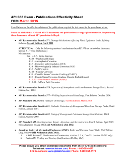
THE AMERICAN SOCIETY OF MECHANICAL ENGINEERS
345 E. 47th St., New York, N.Y. 10017
C
i^
C
J
m ®
93-GT-247
The Society shall not be responsible for statements or opinions advanced in
papers or discussion at meetings of the Society or of its Divisions or Sections,
or printed in its publications. Discussion is printed only if the paper is published in an ASME Journal. Papers are available from ASME for 15 months
after the meeting.
Printed in U.S.A.
Copyright © 1993 by ASME
REPAIR JOINTS IN NICKEL-BASED SUPERALLOYS
WITH IMPROVED HOT CORROSION RESISTANCE
K. A. ELLISON, P. LOWDEN AND J. LIBURDI
Liburdi Engineering Ltd.
Hamilton, Ontario, Canada
D. H. BOONE
Boone and Associates
Walnut Creek, California, USA
ABSTRACT
Sample repair joints in the nickel-base superalloys Inconel IN713 and IN-738 were tested in the laboratory for Type I high
temperature hot corrosion (HTHC) resistance at 900°C. The
joints were produced using a conventional "wide-gap" brazing
process, having a composition similar to IN-718, and a novel
powder metallurgy repair technique LPM" which in this study
had a composition similar to alloy IN-738. Metallographic
analysis of the resulting structures showed that the IN-718 based
repairs, with and without simple aluminide coatings, had suffered
extensive intergranular attack of the braze joints. However, the
HTHC resistance of cast IN-718 was found to be excellent under
identical test conditions. A comparison of the uncoated LPM'
repair joints and cast IN-738 revealed only subtle differences in
the morphology of the corrosion products; the maximum depths
of attack were similar in each case. Silicon modified aluminide
coatings provided a slight reduction in the rate of attack for the
IN-738 alloy, while simple aluminide coatings were less resistant
to HTHC than the base alloy. Similar results were found for the
LPM joints, however localized coating penetration was
observed in the vicinity of boride particles embedded in the
coatings. These differences in behaviour were interpreted with
reference to the chemical and structural changes brought about by
the use of varying levels of boron as a melting point depressant
in the repair layers.
INTRODUCTION
The repair of service damaged gas turbine engine parts using
diffusion brazing processes is an important industrial activity.
Millions of components, mainly high pressure and low pressure
turbine nozzles, have been repaired by so called diffusion brazing
(DB) or wide-gap brazing (WGB) methods and returned to
service (Anthony and Goward, 1988). Such methods have been
developed and applied not only by the OEM's but also by
independent repair facilities (Duvall, et al, 1978; Smith, Jr. et al,
1984; Ellison, Lowden and Liburdi, 1992)
In spite of these earlier successes, there is a continuing need in
the industry to improve the material properties and extend the
repair limits beyond current DB and WGB processes. Although
some reports indicate that WGB processes are capable of
achieving tensile and creep properties approaching those of the
parent superalloys, independent testing and field experience
suggests that these repair materials do not always possess the
same degree of oxidation and hot corrosion resistance as the
parent alloys (Jahnke and Demny, 1983; Boone, Ellison and
Liburdi, 1992). Since many of the components currently being
repaired require high temperature coatings, the performance of
the coated repair joints is a key concern, especially since during
the formation mechanisms of simple and modified aluminide
coatings, the substrate elements will be incorporated to varying
degrees into the final coating.
Liburdi Engineering Ltd. has recently developed and introduced
the LPM'"' repair process which is designed to extend the repair
limits of existing WGB as well as TIG welding processes
(Ellison, Lowden, and Liburdi, 1992). Based on its composition,
the LPM T"' repair material was also expected to offer improved
hot corrosion resistance compared to the existing WGB materials.
In the present study, laboratory hot corrosion tests were
performed on coated and uncoated powder metallurgy repair
joints in nickel-base superalloys using both LPM TM' and a
"standard" WGB material. The properties of the repair joints
were compared to those of cast superalloys having almost
identical compositions. The standard WGB process selected for
comparison was one which was specifically developed to provide
improved hot corrosion resistance for the repair of nickel-base
alloys (Smith, Jr. et al, 1984).
`LPM' is a trade mark and proprietary and patented technology of
Liburdi Engineering Limited.
Presented at the International Gas Turbine and Aeroengine Congress and Exposition
Cincinnati, Ohio — May 24-27, 1993
Downloaded From: http://proceedings.asmedigitalcollection.asme.org/ on 03/09/2015 Terms of Use: http://asme.org/terms
I
I
TABLE 1 - BULK CHEMICAL COMPOSITIONS OF SUBSTRATE AND FILLER ALLOYS USED FOR HOT
CORROSION TESTING
Alloy
Ni
Cr
Co
IN-738
IN-718
IN-713
61.5
53.4
74.1
16.0
19.0
12.0
8.5
Element
Mo
Al
Fe
Ti
18.0
3.4
0.9
0.7
Ta
B
C
0.85
0.12
5.0 (Cb+Ta)
0.1
2.0
1.75
0.01
0.01
0.13
0.05
0.05
0.09
0.62
5.0 (Cb+Ta)
1.96
0.75
1.27
0.09
0.05
W
Cb
2.6
Zr
Substrate Alloys
3.4
0.6
6.0
1.75
3.0
4.5
Filler (Repair) Alloys
LPM T
"'
WGB
63.1
52.1
15.5
19.0
8.9
18.0
2.46
0.9
3.43
0.6
EXPERIMENTAL
1.27
3.0
1.88
TABLE 2 - PROCESSING SEQUENCES USED TO PREPARE
SAMPLE REPAIR JOINTS IN IN-738 AND IN-713
SUBSTRATES.
Materials
Inconel alloys IN-713, IN-738 and IN -718 were selected as
substrates in these tests in order to (i) provide baseline data for
the repair joints with similar compositions and (ii) to provide a
range of chromium compositions which would be expected to
exhibit varying degrees of hot corrosion resistance under these
conditions.
As stated above, two repair materials were evaluated. WGB
processes are typically comprised of a two-component powder
alloy mixture. The first alloy powder is normally selected for its
high melting range, good strength and environmental resistance
and in many cases has a composition similar to that of the base
alloy being repaired. The second lower melting range alloy is
usually nickel-base, containing elements from the group Co, Cr,
Al, Ta, and with additions of B and/or Si as melting-point
depressants. These mixtures are suspended in organic binders
and applied to the surfaces of the cleaned defects. During a
subsequent vacuum heat treatment, the articles to be repaired are
heated to a temperature at which the second alloy powder melts
and the mixture flows into defects. Transient liquid phase
solidification occurs when boron is diffused into the remaining
superalloy powder and the surrounding parent metal. In the
present work, the WGB chemistry was identical to Inconel alloy
IN -718, except that boron was added to one component to form
the low-melting alloy. This mixture was reported to have good
hot corrosion resistance relative to previous WGB materials
(Smith, Jr. et al, 1984).
The LPMTm repair material for these tests was based on the
chemistry of Inconel alloy IN -738. A description of the basic
processing steps has been given elsewhere (Ellison, Lowden, and
Liburdi, 1992) however it is important to note here that this
repair material has a total boron level which is almost half that of
the WGB process. The compositions of both of the above repair
materials, in addition to the three base alloys, are given in
Table 1.
The WGB and LPM TM joints were processed in the IN -713 and
IN -738 substrates using procedures listed in Table 2. For the
Cut sample blanks
Belt dress all surfaces to 120 grit finish
Tack weld paired blanks to produce constant gap widths
(0.7-0.8 mm for WGB; 6-7 mm for LPM)
Remove welding oxides by local grinding
Degrease in acetone and alcohol
LPMTM
WGB
Cut 3 mm wide samples with repair joint at centre
Grind all surfaces to 120 grit finish
Degrease in acetone and alcohol
purpose of this study, a 0.7-0.8 mm (0.027-0.031 inch) constant
gap width was used for WGB material, as dictated by the
limitations of this process. The LPM TM joints were 6-7 mm
(0.23-0.28 inches) in width, reflecting the extended repair limits
possible with this technique (Ellison, Lowden and Liburdi, 1992).
To simulate actual repair applications, some of the samples were
coated using standard commercial pack or slurry aluminide
coatings, which are summarized in Table 3. Finally, coated and
uncoated IN -718 samples were included in the corrosion tests for
comparison to the WGB mixture.
Tests and Analysis Methods
The hot corrosion tests were completed at 900°C in a threezone Lindburgh furnace. The samples were exposed for 100 h in
Downloaded From: http://proceedings.asmedigitalcollection.asme.org/ on 03/09/2015 Terms of Use: http://asme.org/terms
^=
yI
6
5
`
:+3
0
100
200
300
700
400
000
600
KINETIC ENERGY, EV
800
900
100
100
OUR
JUW
.9.
vv
Ovv
svv
•v.
B
6
S
4
V13
2
0
...
URU
KINETIC ENERGY, EV
FIGURE 2 - AUGER SPECTRA FROM (A) THE BULK OF
THE WIDE GAP BRAZE ALLOY AND (B) ONE OF THE
BLOCKY GRAIN BOUNDARY PRECIPITATES (BEFORE
CORROSION TESTING).
FIGURE 1 - OPTICAL MICROGRAPHS SHOWING THE
BULK STRUCTURE OF (A) THE WIDE GAP BRAZE AND (B)
LPM TM JOINTS. ETCH: 100 ml HCI, 50 ml H 2 O, 1 g
POTASSIUM METABISULPHITE, 1 g FERRIC CHLORIDE.
RESULTS
a flowing mixture of 0.5% SO 2 in air. The samples were
weighed, preheated to 150°C and sprayed with a water solution
containing a 60:40 mixture of Na 2SO 4 :MgSO 4 . After drying, the
samples were re-weighed and re-sprayed in order to leave a
uniform coating of 1.5 to 2 mg/cm 2 of the salt on each sample.
The samples were removed from the furnace at 25 h intervals,
examined and re-salted using the above procedure. These test
conditions have been shown to produce so-called high
temperature, Type I hot corrosion.
After the 100 h exposure, the samples were removed from the
furnace, examined visually and mounted for optical
metallography. Some polished sections were analyzed prior to
HTHC testing by scanning Auger electron spectroscopy (AES) in
order to obtain chemical compositions from individual phases
within the repair joints.
Joint Microstructures
Micrographs showing the joint structures prior to the hot
corrosion tests are given in Figure 1. The grain size of the WGB
and LPM T"' repairs were 24±12 µm and 118±27 µm,
respectively. At 200-400x magnification, the structures appear
to be two-phase, consisting of blocky or elongated grain boundary
precipitates (white) and a darker grey matrix phase. The volume
fractions of the grain boundary phases were estimated to be
15.7±3.6% (WGB) and 9.2±3.5% (LPM TM ). At higher
magnifications, the y' structures within the LPM TM grains became
visible.
The compositions of the various phases in the WGB and LPM T""
joints were analyzed by AES. Figure 2 shows AES spectra from
3
Downloaded From: http://proceedings.asmedigitalcollection.asme.org/ on 03/09/2015 Terms of Use: http://asme.org/terms
s
A
2 m
j
25 prn
e
20 cm
20 ,m
FIGURE 3 - LTHA COATINGS ON (A) WGB AND (B) IN-718. HTLA COATINGS ON (C) WGB AND (D) IN-718.
BORIDE PARTICLES FROM THE WGB SUBSTRATE WERE INCORPORATED INTO THE COATINGS OR REPRECIPITATED ALONG THE COATING-ALLOY INTERFACE.
investigators identified blocky Cr 5B 3 precipitates at intergranular
regions having similar morphologies to those observed here. It
is likely that the significantly reduced volume fractions of boride
phases in the intergranular regions of the LPM"" joints were
directly related to the reduced overall boron content of this filler
material.
the WGB joint. The grey matrix phase gave spectra containing
all elements expected from the bulk chemistry, within the limits
of detection (0.1-1 atomic percent). The blocky grain boundary
precipitates in the WGB contained high concentrations of B, Cr
and Mo. Similar results were obtained for the LPM' "' joints.
A review of phase stability diagrams in the Ni-Cr-B systems
shows that boron has less than 1 wt% (5 at%) solubility in FCC
nickel (Hoppin and Levinstein, 1962) and nickel-rich Ni-B alloys
form a Ni,Ni3 B eutectic at 3.6 wt% (17 at% B) at 1093°C
(Massalski, et al., 1986). However, B also forms high melting
point compounds with elements such as Cr, Mo, Zr, etc. (Post,
1964). The formation of refractory metal boride phases in filler
metal and base-metal diffusion zones in wide-gap nickel-base
superalloy joints has been documented in previous studies (Jahnke
and Demny, 1983; Lasalmonie, 1987). Each of these
Coated Joints
Micrographs of the initial coating structures on the WGB and
LPM'"' are shown in Figures 3 and 4 and compared to the IN718 and IN-738 parent alloys. The thicknesses of the various
coatings on the repair joints were approximately equal to those of
the corresponding base alloys. However, there were distinct
morphological changes in the coatings on the WGB and LPM'
4
Downloaded From: http://proceedings.asmedigitalcollection.asme.org/ on 03/09/2015 Terms of Use: http://asme.org/terms
FM
00
N
z
cc
i
f^ ^^ 1 ^ F
G,.
T
1
'1
3r.
1
11'
J9
}
r
sG
1
f
F Z^
I
F
Y. ^ +a1
s
^
F'
SA
1
v
I
Z
Q
.-n
O
z
U
0
J
Cl)
LL
W
J
_
U
H
N
W
H
cc
H
Cl)
m
Cl) w
M00 FnLL
Z ^
r` 0
z
a
J
z
0
N
(D
z
I-
0
0
w
U
z
C
D
D
cc
LU
LL
V1
Downloaded From: http://proceedings.asmedigitalcollection.asme.org/ on 03/09/2015 Terms of Use: http://asme.org/terms
TABLE 3 - MAXIMUM DEPTHS OF CORROSION PENETRATION'.
Type I Hot Corrosion Test: 900 ° C, 100h, 0.5%SO 2 in air,
1.5-2.0 mg/cm 2 Na 2SO 2 :MgSO 4 (60:40)
Alloy or Repair
Material
Surface Pretreatments
Uncoated
Pack Aluminide 2
IN-713
IN-738
IN-718
750
16
28
600 (P 5
50
75 (P)
WGB
LPM T
750
20
400 (P)
75 (P)
"'
)
Vapour Phase
Aluminide3
600 (P)
150 (P)
150 (P)
520 (P)
50 (P)
Silicon Modified
Aluminide°
-
10
-
-
75 (P)
1. In units of micrometers, measured as the combined thickness of external scale and internal precipitation zones.
2. Also known as a Low Temperature, High Activity (LTHA) coating. Pack processing at 700-900°C, Post coat diffusion heat
treat at 1080°C/4h.
3. Also referred to as a High Temperature, Low Activity (HTLA) coating. Processing/diffusion at 1080°C/4h.
4. AI-12Si powder slurry coating. Diffusion heat treated at 870°C/2h.
5. P denotes local penetration of coating to base metal.
substrates. These differences were primarily associated with the
incorporation of chromium boride phases within and beneath the
aluminide coatings.
The LTHA coatings, which grow mainly by the inward
diffusion of aluminum through the /3-NiAI phase during diffusion
heat treatment at 1080°C (Goward and Boone, 1971), had
substrate boride phases distributed throughout the entire coating
structures for both the WGB and LPM' "'' joints. In addition,
there were local breaks or gaps in the coatings above these
embedded particles, exposing the boride phases. AES analysis on
a cross section of the LTHA coating on the WGB substrate
confirmed that a continuous layer of borides had developed in the
inner coating zone. This precipitate zone was absent in the
LTHA-coated IN-718 alloy. The IN-738 and IN-713 substrates
developed multi-phase inner zones typical of TiC, M 23 C 6 and
a(Cr,Mo) precipitation in a i3-NiAl matrix (Goward and Boone,
1971). However, the morphology of the precipitates in this same
zone on the LPMT"' joint had changed from rounded to angular
plates. Due to the limited solubility of chromium, molybdenum
and other substrate alloying elements in Q-NiAl, it is possible that
the continuous boride layer in the inner coating zones formed as
these elements were rejected from the advancing (3-NiAl layer,
with boron being supplied from the substrate.
While the HTLA coatings on the WGB and LPM' joints were
thinner than the respective LTHA coatings, they were
characterized by a distinct absence of boride phases in the outer
coating zones. The inner coating zones were similar to those
observed for the respective LTHA coatings. Furthermore, there
were no breaks in the coating above boride particles as observed
in the case of the LTHA coatings.
Finally, the silicon-modified coating on the LPMT"' joints and
IN-738 substrates were thicker than either of the simple aluminide
coatings described above. The boride particles were concentrated
in the inner half of the coating and there were correspondingly
fewer gaps above these particles.
Hot Corrosion Behaviour - Uncoated Alloys and Repair
Joints
The maximum depths of corrosion attack on the base alloys and
repair materials are given in Table 3. As expected, the IN-713
had the least resistance to HTHC of the three base alloys tested.
This may be interpreted in terms of the relative concentrations of
elements which are known to be beneficial or detrimental for
corrosion resistance (Pettit and Giggins, 1987). Chromium has
been identified as perhaps the most beneficial of the alloying
elements since it may form protective Cr2 0 3 scales and inhibits
basic fluxing of oxides of Ni, Co, Fe. The refractory elements
such as Mo, W, V are known to produce detrimental effects
when mechanism of corrosion is acidic fluxing. IN-713 has the
lowest Cr content, and contains relatively high levels of Mo. The
improved hot corrosion resistance of IN-738 and IN-718 was
thought to be primarily due to higher Cr contents in these alloys.
Of the two repair materials, the WGB was attacked almost as
badly as IN-713. In contrast, the LPMTM' joints showed depths of
attack which were nearly identical to the parent IN-738 alloy.
Micrographs of the hot corrosion reactions on the WGB and IN718 are shown in Figure 5. The WGB exhibited a catastrophic
rate of attack, as shown by the rapid penetration of corrosion
products along grain boundaries and the formation of thick
Downloaded From: http://proceedings.asmedigitalcollection.asme.org/ on 03/09/2015 Terms of Use: http://asme.org/terms
+
^^7t
y
at
om
: tea
N-713
IN-71a20am
IN-713
_
250µm
WGB
Substrate —off—Joint -1 4
y
t
M
Substrate
Internal oxidation
zone
Sulphide precipitation
zone
^` S
S
B
g
_
r
-s
Boride precipitates
in WGB Joint
33Ogm
FIGURE 5 - MICROGRAPHS OF (A) IN-718 AND (B,C) A WGB JOINT AFTER 100 HOUR HOT CORROSION TEST.
THE CHROMIUM BORIDE PARTICLES (B) APPEARED TO BE DISSOLVING INTO THE MATRIX AHEAD OF THE
SULPHIDE PRECIPITATES (S).
external scales. Alloy IN-718 exhibited only very thin corrosion layers and very little internal precipitation. Based on the morphology of the reaction products, it appeared that the
corrosion reactions on the WGB joint grain boundaries were
proceeding by the formation of chromium sulphide particles
which were converted to oxides at a later stage. Furthermore,
7
Downloaded From: http://proceedings.asmedigitalcollection.asme.org/ on 03/09/2015 Terms of Use: http://asme.org/terms
20µm
FIGURE 7 - LTHA COATING ON THE WGB AFTER 100
HOUR HOT CORROSION TEST. PENETRATION AND
SUBCUTANEOUS ATTACK OF THE COATING HAD
OCCURRED BUT THE BORIDE PARTICLES WITHIN THE
COATING WERE STABLE OR HAD REACTED VERY
SLOWLY DURING THE EXPOSURE.
Coated Joints and Alloys
In general there was very little attack of the LTHA and HTLA
coatings on IN-718, however there were localized areas where
the coating had been completely consumed. There was no further
propagation of the corrosion reactions into the alloy beneath these
breaks in the coatings. The same aluminide coatings on the WGB
produced no significant increase in resistance to HTHC. As
shown in Figure 7, the LTHA aluminide coating was partially
intact over some areas of the joint, but had been completely
penetrated in other areas with subcutaneous coating attack and
catastrophic corrosion of the underlying joint. The HTLA
coating on the WGB had been completely consumed during the
100 h test and the depth of corrosion attack in the joint was
comparable to the uncoated WGB. Examination of the partially
intact LTHA coating on the WGB joint revealed that the boride
particles in and beneath the coating were stable or had reacted
very slowly in the HTHC environment, even though the
surrounding matrix was being consumed.
Relative to IN-718, the LTHA and HTLA coatings on IN -738
were less resistant to HTHC. There was general attack of each
type of coating with areas of complete coating penetration.
Propagation of the corrosion reactions into the IN-738 alloy
beneath these areas appeared to be somewhat more advanced than
for the uncoated IN -738. The same general observations applied
to the LPM T"' joints coated with LTHA and HTLA aluminides.
Moreover, as in the case of the LTHA-coated WGB joint, the
boride particles which had been incorporated into each of the
coatings during formation stage did not appear to have reacted
with the test environment. However, the coating around many of
FIGURE 6 - SURFACES OF UNCOATED (A) IN-738 AND
(B) LPMT M JOINT AFTER 100 HOUR HOT CORROSION
TEST. DEPLETION OF THE CHROMIUM BORIDES IN THE
LPM TM ALLOY WAS OBSERVED IN A ZONE BENEATH THE
THIN EXTERNAL SCALE.
the boride particles did not appear to be selectively attacked, but
were dissolving ahead of the sulphide precipitation front.
The corrosion products foamed on uncoated LPM r "" and IN-738
are compared in Figure 6. IN-738 formed a thin external scale
and the formation of internal precipitates was detected under this
outer layer. The morphology of the internal precipitates was
once again typical of chromium sulphide particles which are often
observed beneath external scales and the depleted zones on this
alloy in hot corrosion tests. As shown in the micrographs, the
LPM' and IN-738 corrosion morphologies were almost
identical. It was interesting to note that not one boride particle
could be found in the LPM T "' filler material which intersected the
exposed surface of the joint. They in fact appeared to have been
depleted in a zone immediately underneath the alloy surface.
8
Downloaded From: http://proceedings.asmedigitalcollection.asme.org/ on 03/09/2015 Terms of Use: http://asme.org/terms
100m
µ
100 im
;
-
n ^J^
:
C, - -
s
__
100p.m
10.0^ihi
FIGURE 8 - (A) IN-738 AND (B) LPM TM JOINT WITH PACK
ALUMINIDE COATINGS AFTER 100 HOUR HOT
CORROSION TEST. ALTHOUGH THE COATINGS WERE
PARTIALLY CONSUMED, THERE WAS NO SIGNIFICANT
ATTACK OF EITHER SUBSTRATE.
FIGURE 9 - SILICON MODIFIED ALUMINIDE COATINGS
ON (A) IN-738 AND (B) LPM TM JOINT AFTER 100 HOUR
HOT CORROSION TEST. THE SILICON ADDITION
RESULTED IN IMPROVED COATING PERFORMANCE
RELATIVE TO THE SIMPLE ALUMINIDES AND NEITHER
SUBSTRATE WAS ATTACKED.
these particles had been locally consumed, leaving the boride
particles directly exposed to the corrosive environment (Figure
8).
Finally, the silicon-modified coating exhibited the greatest
resistance to HTHC of all those studied on the IN-738 alloy.
There were no local breakthroughs and the coating had lost very
little of its original thickness. The LPM T"" joint coated with this
material was also essentially un-attacked, even in those cases
where the coating was partially penetrated by boride particles
DISCUSSION
These tests clearly demonstrated that the selection of a powder
metallurgy (WGB) repair material which is based on an alloy
with good hot corrosion properties will not necessarily lead to a
joint which has equally good environmental resistance. The
reduction in the properties of the IN-718 WGB system relative to
the cast IN-718 alloy demonstrated this clearly. What is
interesting, however, is that the LPM TM repair material performed
as well as the cast IN-738 alloy. Obviously, since alloy
composition has such a strong influence on hot corrosion
behaviour, the relative effects of "high" and "low" boron
(Figure 9).
9
Downloaded From: http://proceedings.asmedigitalcollection.asme.org/ on 03/09/2015 Terms of Use: http://asme.org/terms
I
Finally, due to the electrochemical nature of the HTHC
reactions, the influence of the boride precipitates and dissolved
boric oxide (M.P. 450°C) on the local melt chemistry and
corrosion reactions should also be considered. It has been
demonstrated that molten boric oxide can be highly corrosive to
many alloys above 900°C (Roller and Andrews, 1959). If a
liquid boron oxide phase were to form in the substrate, it could
lead to excessively fast oxidation and disintegration of the alloy.
The liquid phase might penetrate along grain boundaries in the
scales which could then become rapid diffusion paths for the
reacting species. Alternatively, if the molten oxide formed at the
scale-alloy interface or beneath the coating it could lead to a loss
of mechanical adhesion, thereby negating the protective properties
of either. Boron oxide also vaporizes rapidly, which would
further complicate the corrosion mechanism (Rizzo, 1960). In
view of the above considerations, a more detailed interpretation
of the corrosion reactions does not seem possible at this time.
additions must be considered when comparing these two systems.
In an earlier report concerning the hot corrosion properties of
uncoated WGB materials, it was suggested that catastrophic attack
of the repair material was due to the low chromium content in the
intergranular regions (Jahnke and Demny, 1983). The boride
precipitation reactions in the present tests and the localized attack
of the WGB prior-particle boundaries gives credence to this
theory, however, analysis of chromium concentrations in the
vicinity of grain boundaries for both repair materials would help
to substantiate this conclusion. Indirect evidence of low
chromium levels in the boundaries of the WGB may also be
indicated by the fact that the chromium boride particles were
dissolving in front of the sulphide precipitation front.
Furthermore, the overall levels of chromium depletion would
depend on the relative amounts of chromium and boron in the
joints. In this respect, the LPM T "' repairs might be expected to
have better hot corrosion resistance due to the lower overall
boron additions, however the IN -718 alloy contains higher
chromium levels which could offset any depletion by boride
precipitation.
Simple calculations of chromium depletion were made based on
the assumptions that boron dissolved in the FCC joint matrix up
to its solubility limit, and that the balance reacted to form Cr 5B 3
precipitates. An overall chromium depletion of 5.8 wt% was
predicted for the WGB joints as opposed to 2.6 wt% for the
LPM"" material, although the final chromium contents were
almost equal at 12.2 and 12.8 wt%, respectively. Obviously, the
corrosion resistance of the depleted matrix will also depend on
the balance of elements present after any chromium depletion has
taken place.
With respect to the coated alloys and joints, it is germane to
point out that the simple LTHA and HTLA aluminides are not
generally considered to be resistant to this form of environmental
attack. It is likely that chromium-containing coatings would have
provided better protection against HTHC. In support of this, it
was noted that the simple aluminides on IN-718 were more
resistant than the same type of coatings on IN-738, which
contains less chromium. The good HTHC resistance of the
silicon-modified aluminide on both LPM T "' and IN -738 was also
consistent with previous data for this coating.
The simple aluminide coatings are applied primarily to improve
the high temperature oxidation resistance of superalloy materials.
In this regard, it is interesting to compare these results to those
of a previous test program in which these same coated and
uncoated joints were submitted for cyclic oxidation testing at
1100°C. In these earlier tests, the uncoated WGB joints were
more rapidly consumed than the LPM T "' joints under cyclic
oxidation conditions; the reactions proceeded by internal
oxidation of the WGB boundaries along with the formation of
thick non-protective scales. However, the uncoated LPM TM' joints
did not form protective oxides and were more rapidly consumed
than the uncoated IN -738 base alloy. The simple LTHA and
HTLA aluminide coatings were more effective in preventing
attack of the LPM T"' repair joints relative to the WGB material,
and the oxidation resistance of the silicon-modified LPM T"' joints
was excellent (Boone, Ellison and Liburdi, 1992).
CONCLUSIONS
Hot corrosion tests were performed on standard WGB and
LPM'"' repair joints in nickel base superalloys. WGB joints
based on IN -718 alloy with and without standard aluminide
coatings suffered extensive intergranular attack of the braze
joints, while cast IN-718 had good corrosion resistance in the
same tests. LPM'"' repairs based on alloy IN-738 with low boron
additions showed excellent hot corrosion resistance, equivalent to
that of the cast IN-738 alloy.
ACKNOWLEDGEMENTS
The authors wish to thank V. Lamanna for help with sample
preparation and S. Sawyer for assistance with the hot corrosion
testing.
REFERENCES
Anthony, K. C. and Goward, G. W., 1988, "Aircraft Gas
Turbine Blade and Vane Repair", Superalloys 1988 , Duhl. D. N.,
Maurer, G., Antolovich, S. and Lund, S., eds., The
Metallurgical Society, pp. 745-754.
Boone, D. H., Ellison, K. A. and Liburdi, J., 1992, "The
Effect of Braze Repair Techniques on the Cyclic Oxidation
Behaviour of Uncoated and Coated Nickel-Base Superalloys",
Presented at 3rd International Symposium on High Temperature
Corrosion and Protection of Materials", Les Embiez, France.
Duvall, D. S., Owczarski, W. A., Paulonis, D. F. and
Schaefer, R. P., 1978, "Metallic Filler Material", U.S. Patent
No. 4,073,639.
Ellison, K. A., Lowden, P. and Liburdi, J., 1992, "Powder
Metallurgy Repair of Turbine Components", ASME paper 92GT-312, presented at the ASME Gas Turbine and Aeroengine
Congress and Exhibition, Cologne, Germany.
10
Downloaded From: http://proceedings.asmedigitalcollection.asme.org/ on 03/09/2015 Terms of Use: http://asme.org/terms
Goward, G. W. and Boone, D. H., 1971, "Mechanisms of
Formation of Diffusion Aluminide Coatings on Nickel-Base
Superalloys", Oxidation of Metals, Vol.3, pp.475-495.
Hoppin, G. S. and Levinstein, M. A., 1962, "Elevated
Temperature Nickel-Base Brazing Alloys", U.S. Patent No.
3,024,109.
Jahnke, B. and Demny, J., 1983, "Microstructural
Investigations of a Nickel-Based Repair Coating Processed by
Liquid Phase Diffusion Sintering", Thin Solid Films, Vol. 110,
pp. 225-235.
Lasalmonie, A., 1987, "Diffusion Brazing of Some Nickel-Base
Superalloys: Some Basic Aspects", Ann. Chim. Fr., Vol. 12, pp.
247-257.
Massalski, T. B., Murray, J. L., Bennett, L. H. and Baker,H.,
eds., 1986, "Binary Alloy Phase Diagrams", Vol 1., American
Society for Metals, Metals Park, pp. 370-371.
Pettit, F. S. and Giggins, C. S., 1987, "Hot Corrosion", in
Superalloys II, Sims, C. T., Stoloff, N. S. and Hagel, W. C.,
eds., John Wiley & Sons, New York, pp. 327-358.
Post, B., 1964, "Refractory Binary Borides", in Boron,
Metallo-Boron Compounds and Boranes, Adams, R. M., ed.,
Interscience Publishers, New York, pp. 301-371.
Rizzo, H. F., 1960, "Oxidation of Boron at Temperatures
Between 400 and 1300 ° C in Air", in Boron Synthesis, Structure
and Properties, Kohn, J. A., Nye, W. F., and Gaule, G. K.,
eds., Plenum Press, New York, pp. 175-189.
Roller, D and Andrews, C. R., 1959, "The Effect of Molten
Boric Oxide on Selected High Temperature Alloys", Corrosion,
Vol. 15, pp. 85t-96t.
Smith, Jr., M. S., Perkins, R. J., Fryxell, R. E. and Young,
W. R., 1984, "Homogeneous Alloy Powder", U.S. Patent No.
4,478,638.
11
Downloaded From: http://proceedings.asmedigitalcollection.asme.org/ on 03/09/2015 Terms of Use: http://asme.org/terms


© Copyright 2026