
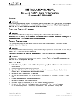
Eaves Beam - Wall Plate - Glazing Bar Installation
Eaves Beam Installation
Step 1 - Measure overall external width of
conservatory along front edge, add 15mm
to each side, if cladding is used for gable
triangle(s) and cut eaves beam
Silicone seal around
glazing bar top caps
against back plate
When cutting
glazing bars
allow 40-60mm
overhang in gutter
fix position using self tapping screws
at approx 1000mm centres. Re-fit
internal PVC cladding
Step 4 - Decide the position
of the glazing bars and cut a
notch in flipper gasket where
it crosses the eaves beam. Fix
glazing bars down using self
tapping screws
NOITALLATSNI MAEB SEVAE
EAVES BEAM INSTALLATION
When cutting polycarbonate roof panels
Step 2 - Remove the variable angle plate
and internal PVC cladding from the eaves
beam. Place eaves beam onto front frames
ensuring that the front lip overhangs. Fix
into frames using self tapping screws at
approx. 600mm centres
Step 3 - After fixing the wall plate adjust the
variable angle plate to suit correct ‘tilt’ and
add 10mm to the glazing bar length
Variable
angle
plate
Step 5 - Trim PVC end caps to
angle and fix. Attach guttering to the
outside of eaves beam
Variable Pitch
From 2.5º – 30º
EAVES BEAM INSTALLATION
Wall Plate Installation
Lead flashing and/
or self adhesive
flashing
2.5º
5º
10º
15º
20º
25º
30º
Step 1 - Measure overall external width
of conservatory along the back wall
(remember to add 15mm to each
side, if cladding is to be used for gable
triangle(s) and cut wall plate)
Pitch-Drill
Hole
Position
WALL PLATE INSTALLATION
mm ni htpeD lanretxE
WALL PLATEStepINSTALLATION
4 - Seal joint between hinged
Captive fixing
bolts (supplied
separately in bags
of 10)
Wall plate
channel
flashing plate and wall plate with
silicone. Apply flashing from wall over
hinged flashing plate
Height from top of frames to marker line on wallplate
16mm roof sheets are being
used.
Drill Line Height
thgieH eniL llirD
DRILL LINE HEIGHT
Drill Line Height
External Depth in mm
thgieH eniL llirD
Step 3 - Using chart, decide which pitchdrill hole position is being used and fix
wall plate to masonary at approx. 700 800mm centres
A secondary flipper gasket is provided to replace
standard gasket when 16mm roof sheets are being
used. Note: please request at POS
House wall to outside of frames
Step 2 - Slide captive fixing bolts (2 per
bar) into the wall plate channel move to
glazing bar positions
EXTERNAL DEPTH IN MM
Silicone
this joint
emarF wodniW fO poT
Top of Window Frame Top O
GLAZING
BAR
INSTALLATION
NOITALLATSNI R
AB GN
IZA
LG
Glazing Bar Installation
Variable Angle
Wallplate
16mm
roof sheets are being
Variable
Variable
Angle
Angle
Eavesbeam
Eavesbeam
T: 01495 244323
Pen-y-Fan Industrial Estate,
F: 01495 246686
Crumlin, Nr. Newport,
E: [email protected]
South Wales NP11 3EH UK
www.macrolux.co.uk
Variable
Angle
Macrolux reserve the right to change specification orEavesbeam
product improvement without prior notice.
Drill Line Height
Self Support
Glazing
Bar
Self Support
Glazing
Bar
Top Caps
Universal Edge Glazing Bar
Unit 31, Fern Close,
Drill an 8mm hole
each side 15mm
from the end of the
bar. Locate glazing
When
bars
onto previously
Underside
Of Bar
glazing
bar crosses
positioned
Top
Of
Window
Framecaptive
eaves beam
notch flipper
bolts. Ensure that
gasket
glazing bars are
parallel before
tightening
(max
centres
1000mm)
We recommend that glazing bars are spaced
either
equally
or if
possible to line up with the window mullions. (max centres 1000mm)
Self Support Glazing Bar
Self Support Glazing Bar
Universal Edge Glazing Bar
Variable Angle Wallplate
Captive bolts
slid into the
wall plate
channel.
As per
wall plate
installation
step 2
Universal Edge Glazing Bar
GLAZING BAR INSTALLATION
External Depth in mm
When using edge
bar against an
outside wall shorten
raB foutside
O edisredflashing
nU
the
trim as shown
For cutting
lengths
on glazing
bars and
polycarbonate
sheets, please
refer to eaves
plate diagram
at top of page
Self Support
Glazing
Bar
Self Support
Glazing
Bar
Universal
EdgeEdge
Glazing
Bar
Universal
Glazing
Bar
Using Edge Bar
against a wall:
World Class Polycarbonate
Drilling Location
Screws in top of
Glazing Bars:
used.
Variable Angle Wallplate
Drill Line Height
Underside OfofBar
Underside
Bar
© Macrolux 2015
Ensure that top caps are
clipped down correctly
and silicon seal the butt
join between glazing bar
top cap and back plate


© Copyright 2026