
Cardiac Rhythm Management Devices Perioperative Management Review
䡵 REVIEW ARTICLE Anesthesiology 2001; 95:1492–1506 © 2001 American Society of Anesthesiologists, Inc. Lippincott Williams & Wilkins, Inc. Cardiac Rhythm Management Devices (Part II) Perioperative Management John L. Atlee, M.D.,* Alan D. Bernstein, Eng.Sc.D.† IN the first installment of this two-part communication, we reviewed the indications for an implanted pacemaker or internal cardioverter– defibrillator (ICD), provided a brief overview of how a device is selected, and described the basics of pacemaker and ICD design and function. Here we discuss specific device malfunction, electromagnetic and mechanical interference, and management for patients with a device or undergoing system implantation or revision. As in part I, the NASPE-BPEG (for North American Society for Pacing and Electrophysiology–British Pacing and Electrophysiology Group; sometimes abbreviated as NBG) generic pacemaker code is used to designate pacing modes.1 Device Malfunction Pacemaker Malfunction Pacing malfunction can occur with an implanted pacemaker or ICD because all contemporary ICDs have at least a backup single-chamber pacing capability, and most have dual-chamber pacing as well. Primary pacemaker malfunction is rare, accounting for less than 2% of all device-related problems in one large center over a 6-yr period.2 Some devices have programmed behavior that may simulate malfunction, termed pseudomalfunction.3 For example, failure to pace may be misdiagnosed with programmed rate hysteresis. With rate hysteresis, the pacing cycle duration is longer after a sensed versus paced depolarization. This encourages the emergence of intrinsic rhythm. Pacemaker malfunction is classified as This is the second part of a two-part article. Part I appeared in the November 2001 issue. *Professor of Anesthesiology, Medical College of Wisconsin. †Adjunct Associate Professor of Surgery, University of Medicine and Dentistry of New Jersey; Director of Technical Research, Department of Surgery, and Technical Director, Pacemaker Center, Newark Beth Israel Medical Center, Newark, New Jersey. Received from the Department of Anesthesiology, Medical College of Wisconsin, Milwaukee, Wisconsin, and the Department of Surgery, University of Medicine and Dentistry of New Jersey, Newark, New Jersey. Submitted for publication September 11, 2000. Accepted for publication June 8, 2001. Support was provided solely from institutional and/or departmental sources. Address reprint requests to Dr. Atlee: Department of Anesthesiology, Froedtert Memorial Lutheran Hospital (East), 9200 West Wisconsin Avenue, Milwaukee, Wisconsin 53226. Address electronic mail to: [email protected]. Individual article reprints may be purchased through the Journal Web site, www.anesthesiology.org. Anesthesiology, V 95, No 6, Dec 2001 failure to pace, failure to capture, pacing at abnormal rates, undersensing (failure to sense), oversensing, and malfunction unique to dual-chamber devices (table 1).3,4 To diagnose device malfunction, it is necessary obtain a 12-lead electrocardiogram and chest radiograph and to interrogate the device to check pacing and sensing thresholds, lead impedances, battery voltage, and magnet rate.3,4 Failure to Pace. With a single-chamber pacemaker and failure to pace, there will be no pacing artifacts in the surface electrocardiogram. The intrinsic rate will be below the programmed lower rate limit, which is obtained from the patient’s records or through device interrogation.3,4 Misdiagnosis of failure to pace is possible if the device is inhibited by intrinsic cardiac depolarizations not apparent in the surface electrocardiogram. With a dual-chamber device, no pacing artifacts may be present, or there may be pacing in only one chamber. With the latter, first it must be determined that the device is not programmed to a single-chamber pacing mode. Failure to pace may be intermittent or continuous. Failure to pace is often due to oversensing (see Oversensing). Other causes are an open circuit caused by a broken, dislodged, or disconnected lead, lead insulation defects, or malfunction of other system components. In addition, problems with the lead–tissue interface may explain failure to pace. When failure to pace occurs within 48 h of device implantation, lead dislodgement, migration, and myocardial perforation are probable causes. Misdiagnosis of failure to pace may occur with impending battery depletion, evidenced by the “elective replacement indicator.” The elective replacement indicator rate is not necessarily the same as the nominally programmed rate. Examples of elective replacement indicators are listed in table 3.5 Failure to pace may be misdiagnosed with too-rapid strip-chart recording speeds. If so, the intervals between paced beats appear longer than normal. Finally, the sense amplifier may detect isoelectric extrasystoles (i.e., in the surface electrocardiogram) that properly inhibit stimulus delivery. Failure to Capture. With failure to capture, there will be visible pacing artifacts in the 12-lead surface electrocardiogram but no or intermittent atrial or ventricular depolarizations. To confirm this diagnosis, the device must be interrogated to examine event markers and measured data (e.g., lead impedances and pacing and 1492 PACEMAKERS AND ICDs 1493 Table 1. Categories of Pacemaker Malfunction, with Electrocardiographic Appearance and Likely Cause for Malfunction Category of Malfunction Electrocardiographic Appearance Cause for Malfunction Failure to pace For one or both chambers, either no pacing artifacts will be present in the electrocardiograph, or artifacts will be present for one but not the other chamber Failure to capture Atrial or ventricular pacing stimuli or both are present, with persistent or intermittent failure to capture 1. Rapid pacing rate (upper rate behavior) 2. Slow pacing rate (below lower rate interval) 3. No stimulus artifact; intrinsic rate below lower rate interval Oversensing; battery failure; open circuit due to mechanical problems with leads or system component malfunction; fibrosis at electrode-tissue interface; lead dislodgement; recording artifact Fibrosis at electrode-tissue interface; drugs or conditions that increase pacing thresholds (table 2) 1. Adaptive rate pacing; tracking atrial tachycardia; pacemakermediated tachycardia; oversensing 2. Programmed rate hysteresis, or rest or sleep rates; oversensing 3. Power source failure; lead disruption; oversensing Inadequate intracardiac signal strength; component malfunction; battery depletion; misinterpretation of normal device function Far-field sensing with inappropriate device inhibition or triggering; intermittent contact between pacing system conducting elements Crosstalk inhibition; pacemakermediated tachycardia (i.e., runaway pacemaker; sensor-driven tachycardia; tachycardia during MRI; tachycardia 2° to tracking myopotentials or atrial tachycardias; and pacemakerreentrant tachycardia) Pacing at abnormal rates Undersensing (failure to sense) Pacing artifacts in middle of normal P waves or QRS complexes Oversensing Abnormal pacing rates with pauses (regular or random) Malfunction unique to dual-chamber devices Rapid pacing rate (i.e., upper rate behavior) MRI ⫽ magnetic resonance imaging. Compiled from Levine3 and Mitrani.4 sensing thresholds).3,4 Event markers will identify the release of stimuli and recycling of the device by sensed events. As for causes (table 1), stimulation thresholds may rise during lead maturation (2– 6 weeks after implantation), but this has become far less of a problem since the introduction of steroid-eluting leads and other refinements in lead technology. Nonetheless, pacing thresholds may continue to rise until they exceed maximum pulse-generator output (exit block).3 Transient, metabolic, and electrolyte imbalance,6 –12 as well as drugs and other factors,3,13–19 may increase pacing thresholds (table 2), a circumstance explaining pacing failure. Anesthetic drugs are not a likely cause. It is notable that addition of equipotent halothane, enflurane, Table 2. Drugs and Other Factors That Affect or Have No Proven Effect on Pacing Thresholds Effect Drugs Increase pacing threshold Bretylium, encainide, flecainide, moricizine, propafenone, sotalol Possibly increase pacing threshold Possibly decrease pacing threshold No proven effect on pacing threshold  Blockers, lidocaine, procainamide, quinidine, verapamil Atropine, catecholamines, glucocorticoids Amiodarone; anesthetic drugs, both inhalation and intravenous ICD ⫽ internal cardioverter– defibrillator. Anesthesiology, V 95, No 6, Dec 2001 Other factors Myocardial ischemia and infarction; progression of cardiomyopathy; hyperkalemia; severe acidosis or alkalosis; hypoxemia; after ICD shocks or external cardioversion or defibrillation Myxedema; hyperglycemia Pheochromocytoma; hyperthyroid or other hypermetabolic states 1494 Table 3. Examples of Elective Replacement Indicators That May Affect the Nominal Rate of Pacing Stepwise change in pacing rate ⫽ the pacing rate changes to some predetermined fixed rate or some percentage decrease from the programmed rate. Stepwise change in magnet rate ⫽ the magnet-pacing rate decreases in a stepwise fashion related to the remaining battery life. Pacing mode change ⫽ DDD and DDDR pulse generators may automatically revert to another mode, such as VVI or VOO to reduce current drain and extend battery life. or isoflurane to opiate-based anesthesia after cardiopulmonary bypass did not increase pacing thresholds.20 Newer inhalation anesthetics, intravenous agents, narcotics, and anesthetic adjuncts have not been shown to affect thresholds. Finally, failure to capture may be misdiagnosed because of increased latency, which is the delay between stimulation and the onset of myocardial depolarization. Drugs or imbalances that increase pacing thresholds (table 2) may also increase latency.3 Pacing at Abnormal Rates. Abnormal pacing rates may be an intended or nonintended device function (table 1).3,4 An apparently abnormal rate may correspond to the elective replacement indicator (table 3). Alternatively, output is not visible during bipolar pacing because of the low amplitude of bipolar pacing artifacts. Upper rate behavior is normal device function if it occurs in response to an adaptive-rate sensor. In a dualchamber device, upper rate behavior may be due to pacemaker-mediated tachycardia or tracking atrial tachycardia (see Pacemaker-mediated Tachycardia). Rarely, very rapid ventricular pacing may be due to pacemaker “runaway.” Runaway can occur with a singleor dual-chamber pacemaker, requires at least two system component failures, and may trigger lethal arrhythmias.3 Newer devices have runaway protection circuits that limit the stimulation rate to less than 200 beats/min. Pacemaker runaway is a major challenge.21,22 With severe hemodynamic instability, the following measures may be considered: (1) connect the pacing leads to an external pulse generator and then cut or disconnect the leads from the implanted pulse generator or (2) first establish temporary transvenous pacing and then cut or disconnect the leads.22 Undersensing (Failure to Sense). The cardiac electrogram must have adequate amplitude and frequency content (slew rate) to be sensed properly.3 A signal with apparently adequate amplitude may be markedly attenuated by the sense amplifier if it has a reduced slew rate. Therefore, the filtered signal may not be of sufficient size to be recognized as a valid event; consequently, undersensing may occur. Table 4 elaborates on previously identified causes of undersensing.3,4 As with failure to capture, the onset of undersensing relative to the time of device implantation helps identify the cause. Undersensing occurring shortly after implantation may be due to Anesthesiology, V 95, No 6, Dec 2001 J. L. ATLEE AND A. D. BERNSTEIN lead dislodgement or malposition or to cardiac perforation. If it occurs later, it could be due to battery depletion, system component failure, or functional undersensing (see below). In addition, undersensing may be due to altered cardiac signal morphology secondary to disease progression; myocardial ischemia or infarction; inflammatory changes or fibrosis at the lead-tissue interface, transient metabolic or electrolyte imbalance; or the appearance of bundle-branch block or ectopy. Finally, external or internal cardioversion or defibrillation may temporarily or permanently disable sensing function because of transient saturation of the sense amplifier or direct damage to circuitry or the electrode–myocardial interface. Normal pacemaker function may be misinterpreted as malfunction because of undersensing.3 For example, reversion to an asynchronous pacing mode during continuous interference is necessary to protect the patient against inappropriate output inhibition. Other examples are triggered pacing modes with fusion or pseudofusion beats. With both, pacing artifacts appear within surface electrocardiographic P waves or QRS complexes. With fusion, there is simultaneous myocardial activation by paced and spontaneous depolarizations. With pseudofusion, pacing stimuli do not produce myocardial depolarization. Fusion or pseudofusion can occur because the pacemaker responds to intracardiac depolarization, which may appear isoelectric in more remote surface electrocardiographic leads. Finally, if too-long refractory periods are programmed, intrinsic cardiac events that should be sensed and should reset pacemaker timing do not. Therefore, the timing interval in effect will time out with delivery of a stimulus. This may be ineffective (pseudofusion) or only partially effective (fusion), deTable 4. Causes for Undersensing (Failure to Sense) Inadequate signal amplitude or slew rate Deterioration of intrinsic signal over time Lead maturation Inflammation, fibrosis Progression of cardiac disease Myocardial ischemia–infarction New bundle branch block Appearance of ectopic beats Transient decrease in signal amplitude After cardioversion or defibrillation shocks Drugs, metabolic or electrolyte derangements that increase pacing thresholds (table 2) Component malfunction Battery depletion Mechanical lead dysfunction Recording artifact (pseudomalfunction) Misinterpretation of normal device function Triggered pacing modes Fusion and pseudofusion beats Functional undersensing (too long refractory periods) Functional undersensing initiated by oversensing PACEMAKERS AND ICDs Fig. 1. Cross-talk inhibition. Immediately after the ventricular blanking period (short rectangle; ventricular channel timing overlay), the polarization potential after atrial stimulation is sensed by the ventricular channel (zigzag interference symbol). This is interpreted as an R wave, resetting the ventriculoatrial (VA) interval and ventricular refractory period (VRP). With complete arterioventricular (AV) block and no escape rhythm, ventricular asystole will occur, with atrial pacing faster than the programmed atrial rate. The short vertical lines in the ventricular timing overlay indicate ventricular stimuli inhibited by resetting of the VA interval. ECG ⴝ electrocardiography; PVARP ⴝ postventricular atrial refractory period. Reprinted with permission from Bernstein AD: Pacemaker timing cycles, American College of Cardiology Learning Center Highlights. Bethesda, American College of Cardiology. pending on whether the chamber is completely or partially refractory at the time, respectively. This is an example of functional undersensing, because this behavior can be corrected by reprogramming.3 Oversensing. Any electrical signal of sufficient amplitude and frequency occurring during the pacemaker alert period can be sensed and can reset the timing. For example, ventricular depolarization sensed by an atrial demand pacemaker may cause inappropriate inhibition of stimulus delivery.23 This is an example of “far-field” sensing. Far-field potentials arise in other cardiac chambers or are sensed skeletal myopotentials or other electromagnetic interference (EMI). In a device that provides atrial antitachycardia pacing, far-field sensing of ventricular depolarizations may lead to inappropriate delivery of therapy.24 Far-field sensing of atrial depolarizations by VVI systems is unusual because of the smaller amplitude of P waves.3 Myopotential inhibition has been reported with sensed succinylcholine-induced muscle fasciculations.25 Myopotential inhibition is more likely with unipolar systems because of the proximity of the anode (pulse generator housing) to the pectoral muscles, diaphragm, or abdominal muscles, depending on pulse generator location.3 In addition, intermittent contact between conducting elements of the pacing system may generate small potentials, termed “make-and-break” potentials. If sensed, these may cause inappropriate output inhibition. Any of the described oversensing can be confirmed by programming the pacemaker to an asynchronous mode or by magnet application. If the cause is oversensing, regular asynchronous pacing will resume. However, if the oversensing is due to other causes (e.g., lead-conductor failure, pulse-generator failure, battery depletion, or an open circuit), there will be no pacing. Anesthesiology, V 95, No 6, Dec 2001 1495 Malfunction in Dual-chamber Pacemakers. Crosstalk inhibition and pacemaker-mediated tachycardia are examples of malfunction that is specific to devices that both pace and sense in the atria and ventricles. Crosstalk Inhibition. Crosstalk is the unexpected appearance in the atrial or ventricular sense channel or circuit of electrical signals present in the other.3 For example, polarization potentials after stimulus delivery may be sensed in the ventricular channel during unipolar atrial pacing. If interpreted as spontaneous ventricular events, they can inhibit ventricular output. In the absence of an escape rhythm, there could be asystole, with only atrial pacing artifacts and P waves visible (fig. 1).26 –28 Such cross-talk inhibition can be prevented by increasing the ventricular sensing threshold, decreasing atrial output, or programming a longer ventricular blanking period, so long as these provide adequate safety margins for atrial capture and ventricular sensing. During the blanking period, ventricular sensing is disabled to avoid overloading of the sense amplifier by voltage generated by the atrial stimulus. If too short (fig. 1), this allows the atrial stimulus to be sensed in the ventricular channel, inappropriately resetting the ventriculoatrial (VA) interval without delivery of ventricular stimuli. If cross-talk cannot be prevented, many dual-chamber pacemakers have a cross-talk management feature, referred to in the pacing industry as nonphysiologic atrioventricular (AV) delay or ventricular safety pacing (fig. 2).3 Pacemaker-mediated Tachycardia. Pacemakermediated tachycardia is unwanted rapid pacing caused by the device or its interaction with the patient.3 Pacemaker-mediated tachycardia includes pacemaker runaway; sensor-driven tachycardia; tachycardia during Fig. 2. Nonphysiologic arterioventricular (AV) delay (ventricular safety pacing). Whenever the ventricular channel senses anything during the initial portion of the programmed AV interval (shaded), such as cross-talk interference (zigzag symbol; ventricular timing overlay), a ventricular stimulus is triggered after an abbreviated AV interval to prevent asystole. In beat two, a conducted R wave is sensed and treated as cross-talk because the device does not distinguish spontaneous from paced beats. However, the triggered ventricular stimulus fails to depolarize refractory myocardium (black rectangle; ventricular timing overlay). Furthermore, its premature timing prevents stimulation during the T wave. ECG ⴝ electrocardiography; PVARP ⴝ postventricular atrial refractory period; VRP ⴝ ventricular refractory period. Reprinted with permission from Bernstein AD: Pacemaker timing cycles, American College of Cardiology Learning Center Highlights. Bethesda, American College of Cardiology. 1496 Table 5. Mechanical or Physiologic Interference in the Perioperative Environment That May Be Sensed To Cause Inappropriate High-rate Pacing Vibration sensor—piezocrystal Direct pressure on device (prone position) Bone hammers and saws Bumpy ride (stretcher; hospital beds) Impedance-based sensors—minute ventilation Hyperventilation during induction of anesthesia Mechanical ventilators Electrocautery Environmental 50–60 Hz electrical interference Evoked QT interval Catecholamine surge (stress, pain, pheochromocytoma) magnetic resonance imaging (MRI) or due to tracking myopotentials or atrial tachydysrhythmias; and pacemaker-reentrant tachycardia. Sensor-driven tachycardia. Adaptive-rate devices that sense vibration, impedance changes, or the QT interval may sense mechanical or physiologic interference to cause inappropriate high-rate pacing (table 5). It is advised that adaptive-rate pacing be disabled, even if electrocautery is not used during surgery.3,29,30 Magnetic resonance imaging. Powerful forces exist in the MRI suite, including static magnetic, gradient magnetic, and radiofrequency fields.31–33 The static magnetic field may exert a torque effect on the pulse generator or close the magnetic reed switch to produce asynchronous pacing. Because devices today contain little ferromagnetic material, the former is considered unlikely.33 Pacemaker leads can act as an antenna for the gradient magnetic field and radiofrequency field energy applied during MRI.34 The gradient magnetic field may induce voltage in the pacemaker large enough to inhibit a demand pacemaker but unlikely to cause pacing.32 The radiofrequency field, however, may generate enough current in the leads to cause pacing at the frequency of the pulsed energy (60 –300 beats/min).32,33 In dualchamber pacemakers, this may affect one or both channels.33 Finally, Achenbach et al.31 documented an average temperature increase of 15°C at the electrode tip of 25 electrodes exposed to MRI, with a maximum increase of 63°C. Tachycardia due to myopotential tracking. The atrial channel of a unipolar, dual-chamber device that tracks P waves (i.e., programmed to VAT, VDD, or DDD) may sense myopotentials from muscle beneath the pulse generator, with triggered ventricular pacing up to the programmed maximum atrial tracking rate. This is unlikely with bipolar sensing, currently preferred by many implanting physicians.3 Tachycardia secondary to tracking atrial tachydysrhythmias. Atrial dysrhythmias, notably atrial fibrillation or flutter, may be tracked by ventricular pacing at or near the device’s upper rate interval if programmed to an atrial-tracking mode (VAT, VDD, DDD). Medication to suppress the dysrhythmia or cardioversion may be necAnesthesiology, V 95, No 6, Dec 2001 J. L. ATLEE AND A. D. BERNSTEIN essary. In most instances, placing a magnet over the pulse generator to disable sensing (see Response of Pacemaker to Magnet Application) will terminate high-rate atrial tracking.4 Some dual-chamber pacemakers have algorithms to detect fast, nonphysiologic atrial tachycardia and then switch to a nontracking pacing mode (i.e., automatic mode-switching).35–37 This is a useful feature with complete AV heart block and susceptibility to intermittent atrial tachyarrhythmias. Methods to prevent high rate atrial tracking are shown in figures 3 and 4. Pacemaker-reentrant tachycardia. Pacemaker-reentrant tachycardia (PRT) can occur in any dual-chamber pacemaker programmed to an atrial-tracking mode (e.g., VAT, VDD, DDD). It is a type of reentrant tachycardia that incorporates the pacemaker in the reentry circuit. The patient must have retrograde VA conduction through the AV node or an accessory AV pathway for PRT to occur. Approximately 80% of patients with sick sinus syndrome and 35% of those with AV block have retrograde VA conduction,38 – 40 so more than 50% of patients receiving dual-chamber pacemakers are susceptible to PRT.38 Furthermore, 5–10% of patients with absent VA conduction at the time of device implantation later acquire VA conduction.38,41 Normally, PRT is initiated by a premature ventricular beat. This conducts to the atria and is sensed, provided it occurs outside the total atrial refractory period. The sensed retrograde P wave initiates the AV interval, which times out with Fig. 3. Prevention of high-rate atrial tracking. When sensed P waves fall within the postventricular atrial refractory period (PVARP; first beat; short upward vertical line; atrial timing overlay), it does not trigger ventricular pacing or reset the arterioventricular (AV) interval. The next anticipated paced event is atrial stimulation at the end of the ventriculoatrial (VA) interval (second beat; short vertical line; atrial timing overlay). However, as shown, a spontaneous P wave is sensed, and this initiates a new AV interval before the VA interval times out with delivery of an atrial stimulus. Such intentional failure to track P waves within the PVARP produces “n-to-one block” (as shown, 2:1 block), limiting the minimum ventricular interval to the sum of the AV interval and PVARP. With AV block, as the atrial rate increases above the maximum tracking rate, only every other P wave is tracked, halving the paced ventricular rate. If still faster, two or more P waves may fall within the total atrial refractory period (AV ⴙ PVARP) and fail to trigger ventricular stimuli. ECG ⴝ electrocardiography; VRP ⴝ ventricular refractory period. Reprinted with permission from Bernstein AD: Pacemaker timing cycles, American College of Cardiology Learning Center Highlights. Bethesda, American College of Cardiology. PACEMAKERS AND ICDs Fig. 4. Alternative prevention for high-rate atrial tracking. The minimum ventricular interval (VVmin) is lower than in fig. 3 but greater than the arterioventricular (AV) ⴙ postventricular atrial refractory period (PVARP; atrial channel). When the P-P interval is between AV ⴙ PVARP and VVmin (as shown), the P wave falls outside PVARP and is tracked by ventricular pacing, but after an extended AV interval (> AV), because the ventricular stimulus is delayed until the end of VVmin. Therefore, the interval between sensed P waves and the ventricular stimulus increases with each beat until a P wave falls within PVARP and is not tracked (not shown). This produces “pacemaker” or “pseudo” Wenckebach. ECG ⴝ electrocardiography; VRP ⴝ ventricular refractory period. Reprinted with permission from Bernstein AD: Pacemaker timing cycles, American College of Cardiology Learning Center Highlights. Bethesda, American College of Cardiology. ventricular stimulation. PRT also occurs when paced ventricular beats are conducted back to the atria to trigger ventricular stimulation (fig. 5). To prevent PRT, a longer postventricular atrial refractory period is programmed,3 but this limits the upper atrial tracking rate of the device. For example, some patients have VA conduction times greater than 430 ms.3 Thus, if the postventricular atrial refractory period is 450 ms and the AV interval is 150 ms, the total atrial refractory period is 600 ms. This limits the maximum paced ventricular rate to 100 beats/ min, possibly too slow for an active patient. In some devices, the postventricular atrial refractory period can be programmed to a longer duration after premature ventricular beats to prevent sensing of retrograde P waves. In addition, placing a magnet over the pulse generator will terminate PRT in most devices by disabling sensing and producing asynchronous (DOO) pacing. However, PRT may recur after the magnet is removed. Response of Pacemaker to Magnet Application. Most pulse generators respond to magnet application by pacing asynchronously in a device-specific single-chamber (SOO) or dual-chamber pacing mode (DOO). (An SOO device paces a single chamber, either the atrium or the ventricle.) This corresponds to the programmed magnet mode.42,43 For example, Thera DR or D devices (Medtronic, Minneapolis, MN) pace SOO or DOO at 85 beats/min.43 However, with impending power source depletion, the magnet rate may differ, because it becomes the end-of-life (EOL) or elective replacement indicator. Again, the EOL or elective replacement indicator rate is characteristic for specific devices (e.g., VOO at 65 beats/min for the Thera DR and D devices).43 Anesthesiology, V 95, No 6, Dec 2001 1497 The first few paced beats after magnet application may occur at a rate or output other than that seen later, providing device identification data on the strip-chart electrocardiographic recording as well as information regarding integrity of the pulse generator and leads.42 Magnet application during electrocardiographic monitoring also confirms the ability of the system to capture the appropriate chamber at the programmed output settings.43 In addition, magnets may be useful diagnostically and therapeutically.43 In a patient whose intrinsic rhythm inhibits the device, magnet application may serve to identify the programmed mode when the correct programmer is not available for telemetry.43 Furthermore, with device malfunction due to malsensing, magnet-initiated asynchronous pacing may temporarily correct the problem, confirming the presence of far-field sensing, cross-talk inhibition, T-wave sensing, or pacemaker-mediated tachycardia. Finally, in pacemaker-dependent patients, magnet application may ensure pacing if EMI inhibits output (e.g., in surgical electrocautery). However, if the device has reverted to an asynchronous interference mode (fig. 6), the magnet response may not be the same as when the device is not in the interference mode.42 Finally, it is widely assumed that placing a magnet over any pacemaker pulse generator will invariably cause asynchronous pacing as long as the magnet remains in place. However, in some pacemakers, the magnet response may have been programmed off. In others a variety of magnet responses may have been programmed, some of which do not provide immunity to EMI sensing. In still others, the device will continue to pace asynchronously or pacing will cease after a programmed number of intervals.42 Thus, if possible, one should determine before EMI exposure which pulse generator is present and what must be done to provide Fig. 5. Pacemaker-reentrant tachycardia occurs when a premature ventricular beat with retrograde P wave (second beat) resets the arterioventricular (AV) interval, triggering a ventricular stimulus earlier than expected (i.e., when the ventriculoarterial [VA] interval times out). Pacemaker-reentrant tachycardia may also occur if paced ventricular beats produce retrograde P waves. ECG ⴝ electrocardiography; PVARP ⴝ postventricular atrial refractory period; VRP ⴝ ventricular refractory period. Reprinted with permission from Bernstein AD: Pacemaker timing cycles, American College of Cardiology Learning Center Highlights. Bethesda, American College of Cardiology. 1498 Fig. 6. Asynchronous interference mode in a VVI pacemaker, with temporary VOO pacing at the programmed basic-rate interval. The ventricular refractory period (VRP) begins with a noise-sampling period (black rectangles), during which time the sense amplifier is off. During the rest of the VRP, repeated noise (N) above a minimal frequency (e.g., 7 Hz ⴝ 420 events/min) is interpreted as interference and restarts the VRP. Preempted portions of the VRP are indicated by dashed rectangles. Thus, so long as the noise persists, the device remains refractory, with the escape timing determined solely by the programmed basicrate interval (asynchronous pacing at A). Note that a spontaneous R wave and the second paced beat occur in the noisesampling period. Neither are sensed, but the latter initiates a new VRP. Reprinted with permission from Bernstein AD: Pacemaker timing cycles, American College of Cardiology Learning Center Highlights. Bethesda, American College of Cardiology. protection. If this is not possible, then one can observe the magnet response during EMI to ascertain whether there is protection from EMI sensing. During electrocautery, for example, if despite magnet application the electrocautery triggers rapid pacing or inhibits pacing stimuli in a pacemaker-dependent patient, then the cautery must be limited to short bursts. ICD Malfunction Specific ICD malfunctions include inappropriate shock delivery, failure to deliver therapy, ineffective shocks, and interactions with drugs or devices affecting the efficacy of therapy.44 – 46 Because all ICDs feature single- or dual-chamber pacing, there is potential for pacing malfunction as well (discussed previously). Inappropriate Delivery of Shocks. Electrical artifacts consequent to lead-related malfunction may be interpreted as tachycardia, with inappropriate shock delivery.46 Electrocautery artifact may be similarly misinterpreted.47 Rapid supraventricular or nonsustained ventricular tachycardia (VT) may be misdiagnosed as sustained VT or ventricular fibrillation (VF),44,46 especially if rate-only criteria are used for diagnosis.48 Finally, R and T wave oversensing during ventricular bradycardia pacing has led to inappropriate shocks.49 Anesthesiology, V 95, No 6, Dec 2001 J. L. ATLEE AND A. D. BERNSTEIN Failure to Deliver Therapy or Ineffective Shocks. Magnet application may disable sensing and therefore the ability to deliver therapy (see Response of an ICD to Magnet Application). Especially after repeated subthreshold shocks for VF, tachydysrhythmias may be undersensed and may be the cause of failure to deliver therapy.50 Exposure to diagnostic radiography or computed tomography scanning does not adversely affect shock delivery. Lead-related problems, including conductor fracture, lead migration, and lead insulation defects, may also be responsible for failure to deliver shocks or ineffective shocks.46 Acute myocardial infarction, hypoxia, and severe acid-based or acute electrolyte imbalance may increase defibrillation thresholds, leading to ineffective shocks.44 Any of the latter could also affect the rate or morphology of VT and the ability to diagnose VT. Finally, isoflurane and propofol anesthesia do not affect defibrillation thresholds.51 The effect of other anesthetics or drugs used to supplement anesthesia is not known. Drug–Device Interactions Affecting Efficacy of ICD Therapy. Antiarrhythmic drugs are prescribed along with ICDs to suppress (1) recurring sustained VT and the need for frequent shocks; (2) nonsustained VT that triggers unnecessary shocks and causes premature power source depletion; and (3) atrial fibrillation and inappropriate shocks.46 In addition, they may be used to slow VT to make it better tolerated or more amenable to termination by antitachycardia pacing and to slow AV nodal conduction with atrial fibrillation. Possible adverse effects of combined drug and ICD therapy are that (1) amiodarone slows VT to below the programmed ratedetection threshold; (2) prodysrhythmia (the provocation of new or worse dysrhythmias) occurs with many antidysrhythmic drugs, increasing the need for shocks; (3) defibrillation thresholds may increase; (4) hemodynamic tolerance of VT may be reduced; (5) possible PR, QRS, or QT interval increases can cause multiple counting and spurious shocks; and (6) possible morphologic alterations or reductions in amplitude of cardiac electrograms may lead to failure to detect VT or VF.44,46,52,53 Lidocaine, long-term amiodarone, class 1C drugs (e.g., flecainide), and phenytoin increase defibrillation thresholds.46 Class 1A drugs (e.g., quinidine) and bretylium do not affect defibrillation thresholds.46 Device–Device Interactions Affecting Efficacy of Therapy. Formerly, pacemakers were used for bradycardia and antitachycardia pacing in patients with ICDs. Today, ICDs incorporate both pacing capabilities. However, there still may be an occasional patient with both devices.46 Adverse interactions between devices include the following: (1) sensed pacing artifacts or depolarizations lead to multiple counting, misdiagnosis as VT/VF, and unnecessary shocks; (2) antitachycardia pacing artifacts may be misdiagnosed as VT, triggering shocks; (3) PACEMAKERS AND ICDs ICD shocks may reprogram a pacemaker or cause failure to capture or undersensing.46 Response of an ICD to Magnet Application. Depending on the manufacturer and model of the ICD and how it is programmed (e.g., magnet switch inactivated54), tachycardia sensing and delivery of therapy may be inactivated during exposure to a magnet. However, except for CPI devices (CPI, St. Paul, MN), sensing is inhibited only while the magnet is directly over the pulse generator.55 With CPI devices, magnet application for less than 30 s temporarily disables sensing, whereas that longer than 30 s requires magnet reapplication for longer than 30 s to reactivate sensing. Electromagnetic and Mechanical Interference Pacemakers and ICDs are subject to interference from nonbiologic electromagnetic sources.33 In addition, temperature extremes or irradiation may cause malfunction. In general, devices in service today are effectively shielded against EMI, and increasing use of bipolar sensing has further reduced the problem. EMI frequencies above 109 Hz (i.e., infrared, visible light, ultraviolet, x-rays, and gamma rays) do not interfere with pacemakers or ICDs because the wavelengths are much shorter than the device or lead dimensions.33 However, highintensity therapeutic x-rays and irradiation can directly damage circuitry.33 EMI enters a pacemaker or ICD by conduction or radiation, depending on whether it is in direct contact with the source or the leads act as an antenna, respectively.33 These devices are protected from EMI by shielding the circuitry, reducing the distance between the electrodes to minimize the antenna (e.g., use of a bipolar vs. unipolar lead configuration for sensing), and filtering incoming signals to exclude noncardiac signals. If EMI does enter the pulse generator, noise protection algorithms in the timing circuit help reduce its effect on the patient. However, EMI signals between 5 and 100 Hz are not filtered because these overlap the frequency range of intracardiac signals. Therefore, EMI in this frequency range may be interpreted by a device as intracardiac signals, giving rise to abnormal behavior. Possible responses to EMI include (1) inhibition or triggering of pacing stimulation; (2) asynchronous pacing; (3) mode resetting; (4) damage to the pulse generator circuitry; and (5) triggering of unnecessary ICD shocks.33 Output Inhibition or Triggering and Asynchronous Pacing. To protect the pacemaker against inappropriate inhibition of paced output, some devices will revert to asynchronous pacing at the basic-rate interval when exposed to continuous EMI above a certain frequency (fig. 6). In others, rather than timing out at the basic-rate interval, repetitive detection of noise in the noise-sampling period causes temporary reversion to a specific “noise mode,” typically VOO or DOO.33 Whether EMI noise causes inhibition or asynchronous Anesthesiology, V 95, No 6, Dec 2001 1499 pacing depends on signal duration and field strength.56 At the lowest field strength, there is no effect. However, as field strength increases, there is a greater tendency to inhibition because the noise may be sensed intermittently. Thus, it may not be sensed in the noise-sampling period but in the alert period before the next pacing pulse. With higher field strengths, noise is sensed continuously, and asynchronous pacing occurs. There is considerable variation between pacemakers and their susceptibility to noise.33,56 Another approach for handling EMI is to program a triggered pacing mode (i.e., VVT, AAT).33 Continuous EMI will then trigger pacing at an upper rate determined by the ventricular or atrial refractory period. This is usually set at approximately 400 ms to limit the maximum triggered rate to 150 beats/min. Mode Resetting and Reprogramming. EMI noise may cause a change to another mode that persists after the noise stops.33 This is usually the backup or reset mode, often VVI, and the same as the elective replacement indicator or impending battery depletion mode.33 If so, a pacemaker that has been affected by EMI may be wrongly assumed to have reached battery depletion and be replaced. Alternatively, an operator knowing that a device has been subject to EMI may reprogram one that has truly reached battery depletion.33 Some pacemakers may be reset to the VOO mode, resulting in competition between paced and intrinsic rhythm. To our knowledge, EMI has not reprogrammed ICD antitachycardia therapies or affected bradycardia pacing in ICDs with singleor dual-chamber pacing capability. Although random reprogramming of a pre-1990s pacemaker by electrocautery EMI has occurred,57 such reprogramming is highly unlikely with newer pacemakers, because unique radiofrequency sequences are required to enable programming of these devices. Damage to Circuitry. There can be direct EMI damage to pacemaker or ICD circuitry, resulting in output failure, pacemaker runaway,21 or other malfunction that necessitates pulse generator replacement.33 Pacemakers and ICDs are protected from damage by high-energy current or shocks by special circuitry that electronically regulates the voltage entering the circuitry and should prevent high current from being conducted to the myocardium. Even so, extremely high energies may overcome such protection, causing damage to the device or heart. Bipolar devices appear more resistant than unipolar devices.33 Triggered Shocks. Reports of inappropriate ICD shocks due to EMI oversensing are infrequent.47 A recent report described aborted shock delivery in a patient during facial electrosurgery.58 In this case, EMI was interpreted by the device as VF, but spurious shocks were averted because the noise did not continue beyond the 9-s capacitor charging period. J. L. ATLEE AND A. D. BERNSTEIN 1500 Table 6. Potential Sources of Electromagnetic Interference and Their Effects on Pacemakers with Relevance to Perioperative Management EMI Source Electrocautery External DCDF MRI scanner Lithotripsy RF ablation ECT TENS Radiation therapy Diagnostic radiation Generator Damage Yes Yes Possible Yes† Yes No No Yes No * Impedance-based adaptive-rate pulse generators. Complete Inhibition One-beat Inhibition Yes No No Yes‡ Yes Yes Yes No No Yes No Yes Yes‡ No Yes No No No † Piezoelectric crystal-based pulse generators. Asynch Pacing Yes Yes Yes Yes‡ No Yes Yes No No ‡ Remote potential for interference. Rate Increase Yes*† Yes Yes Yes§ Yes Yes† Yes Yes Yes § DDD mode only. Asynch ⫽ asynchronous; DCDF ⫽ direct current cardioversion or defibrillation; MRI ⫽ magnetic resonance imaging; RF ⫽ radiofrequency; ECT ⫽ electroconvulsive therapy; TENS ⫽ transcutaneous electrical nerve stimulation. Compiled from Hayes and Strathmore33 and Levine and Love.3 Specific Electromagnetic and Mechanical Interference. EMI sources with relevance to perioperative physicians, along with their potential effects on pacemakers, are listed in table 6.3,33 Although devices programmed to a bipolar lead configuration are more sensitive to locally generated signals, they are relatively insensitive to more remote signals. The most important EMI sources are surgical electrocautery and high-energy shocks for cardioversion or defibrillation. Mechanical ventilators and bone hammers or saws may interfere with vibration, acceleration, or minute-ventilation adaptive-rate pacemakers. Surgical Electrocautery. The current generated by unipolar electrocautery is related to the distance and orientation of the cautery tool and grounding plate with respect to the pacemaker or ICD pulse generator and leads.59 The greater the distance, the smaller is the voltage difference measured by the sensing circuit. High current is generated in the pulse generator circuitry if the cautery cathode (bovie tool) is close to the pulse generator, and even higher current is generated if the pulse generator is between the cathode and anode (grounding plate).33 Bipolar cautery produces smaller voltage differences in the sensing circuits. Possible anomalous behavior with electrocautery EMI is described in the section Electromagnetic and Mechanical Interference. In addition, electrocautery may overwhelm the impedance-measuring circuit of a minute ventilation adaptive-rate pacemaker to cause pacing at the upper rate limit.60 Finally, induced currents in the pacing leads may cause heating at the electrode-tissue interface, leading to tissue damage and elevated pacing or sensing thresholds. This is infrequently documented and usually transient.33 Defibrillator or Cardioverter Shocks. External cardioversion or defibrillation produces sufficient energy near a pacemaker or ICD to cause damage to the pulse generator or electrode–myocardial interface.33 Transient elevation of thresholds for pacing and sensing is not Anesthesiology, V 95, No 6, Dec 2001 uncommon after external or internal defibrillation.33 Unipolar pacing systems are more susceptible.33,61 ICDs deliver smaller amounts of energy but also can interfere with pacemaker function.62 ICD shocks likely will activate the backup or reset modes or the elective replacement indicator. However, in devices with programmable lead configuration, unipolar pacing will be delivered by these modes. Because unipolar pacing pulses are more likely to be detected by an ICD, it is essential that a pacemaker in a patient with an ICD be programmed to a bipolar configuration or that the unipolar configuration first be tested to ensure there is no undersensing or oversensing by the defibrillator.33 A pacemaker without programmable lead configurations is preferred for ICD patients.33 Miscellaneous EMI Sources. In general, it is recommended that patients with pacemakers not routinely undergo MRI.33 Recent studies suggest that MRI may be safe, at least with some models of pacemakers or ICDs, provided the pulse generator and leads are not inside the magnet bore.32,63 If MRI must be performed, program the device to its lowest voltage and pulse width or to the OOO mode if the patient has adequate spontaneous rhythm.44,64 The pulse waveform should be closely monitored in pacemaker-dependent patients, and an external defibrillator must be available.33,65,66 Device function must be checked after MRI. Diagnostic radiation has no effect on pacemakers or ICDs. Therapeutic radiation did not affect the earliest pacemakers but can cause pulse generator failure in newer pacemakers that incorporate complementary metal oxide semiconductor–integrated circuit technology.33,67– 69 ICDs may also fail when exposed to radiation. Radiation causes leakage currents between the insulated parts of the circuit, leading to inappropriate charge accumulation in silicon oxide layers, which eventually leads to circuit failure. Therapeutic radiation involves doses up to 70 Gy, and pacemakers may fail with as little PACEMAKERS AND ICDs as 10 Gy.33 Failure is unpredictable and may involve changes in sensitivity, amplitude, or pulse width.33 In addition, loss of telemetry, failure of output, or runaway rates may occur.33,70 If unalterable malfunction occurs, replacement of the device is necessary.33,44 Although some changes may resolve in hours, long-term reliability of the device is suspect. Before a course of radiation therapy is begun, the device must be identified and its function evaluated.33,44,67,69,71 Radiation to any part of the body away from the site of the pulse generator should not cause a problem with the pulse generator, but the pulse generator should be shielded to avoid scatter.33 If this is not possible, the device should be removed and reimplanted as far as possible from beams of radiation. The cumulative dose of radiation energy to which the pulse-generator is exposed should be recorded after each session. Device function should be monitored during therapy and regularly evaluated by telemetry during and after the course of treatment. Adaptive-rate pacemakers that sense mechanical vibration or acceleration may malfunction during orthopedic surgery.33 Positive-pressure ventilation may adversely affect measurement of minute ventilation by adaptive-rate pacemakers.72–74 Electroconvulsive therapy appears safe for patients with pacemakers since little current flows within the heart because of the high impedance of body tissues.33 However, the seizure may generate sufficient myopotentials for pacemaker inhibition (unipolar devices) or ventricular tracking (adaptive-rate devices).33 Extracorporeal shock wave lithotripsy (ESWL) appears safe with pacemakers, provided shocks are synchronized to electrocardiographic R/S waves and dual-chamber devices have the cross-talk management feature enabled (fig. 2).33,71 There may be a rate increase in an activitysensing pacemaker after ESWL shocks. If this is undesirable, the adaptive-rate feature should be programmed off. Programming a DDD pacemaker to VVI, VOO, or DOO is advised to avoid irregularities in pacing rate, tracking of ESWL-induced supraventricular tachyarrhythmias, or triggering of ventricular output by sensed EMI.33 It is best to disable tachycardia detection during ESWL and to thoroughly test the ICD following the procedure.33 Transcutaneous electric nerve stimulation units probably can be used safely in patients with pacemakers or ICDs with bipolar lead polarity.75,76 Nevertheless, it is reasonable to monitor pacemaker or ICD-dependent patients during initial application of transcutaneous electric nerve stimulation. Pacemaker-mediated tachycardia has been induced by intraoperative somatosensory evoked potential stimuli.77 Finally, the effects of radiofrequency catheter ablation for termination of tachydysrhythmias are similar to those of electrocautery and include inappropriate inhibition, asynchronous pacing, and reset to a backup pacing mode.78,79 Anesthesiology, V 95, No 6, Dec 2001 1501 Management for the Patient with a Pacemaker or ICD Preoperative Evaluation. Most patients with pacemakers or ICDs, especially the latter, have significant cardiovascular disease. Many have coexisting systemic disease as well. Special attention is paid to progression of disease, functional status, current medications, and compliance with treatment. No special laboratory tests or radiographs are required because the patient has an implanted pacemaker or ICD. However, results of recent 12-lead electrocardiography and any indicated diagnostic and recent laboratory tests (e.g., for electrolyte status) should be available. Device Identification and Evaluation. Unless the proposed surgery or intervention is truly emergent or poses little risk to the pulse generator or leads (e.g., extremity, ophthalmologic, or other minimally invasive surgery in which bipolar cautery is used), identify the device, as well as date of and indication(s) for its implantation. Because all implanted pacemakers and ICDs are programmable, device interrogation with a compatible programmer is the most reliable, efficient way to determine function, battery status, programmed settings, pacing thresholds, lead impedances, electrode configuration, intrinsic rhythm, and magnet response. These should be recorded and rechecked after the surgery or intervention. Most hospitals today have a pacemaker or ICD clinic or service (or access to one) that should be consulted for device interrogation and reprogramming. For the pacemaker-dependent patient, it is advised that the device be reprogrammed to an asynchronous mode if EMI is likely to cause significant malfunction (e.g., unipolar electrocautery for surgery involving the upper abdomen or chest wall). For patients with adaptive-rate devices (including ICDs), this feature should be programmed off during surgery or exposure to other EMI that might cause device malfunction (table 6). Magnet-activated testing should be programmed off.42 For patients with an ICD, tachycardia sensing should be programmed off. Further, if the patient is also pacemaker-dependent, an asynchronous pacing mode should be programmed if EMI might cause significant inhibition or other undesired function. After the planned procedure, it is necessary to have device function tested by qualified personnel, with the device reprogrammed or replaced if necessary. In smaller hospitals and freestanding surgical or ambulatory care facilities, there may be no one immediately available to perform device interrogation and reprogramming. We strongly advise that under no circumstance should elective surgery or intervention proceed in this circumstance if the patient is at risk for device malfunction that could jeopardize his or her health. In other words, just as for the patient with uncontrolled hypertension or unstable coronary disease, it is necessary to optimize the patient’s status before elective surgery or J. L. ATLEE AND A. D. BERNSTEIN 1502 Table 7. North American Manufacturers of Pacemakers and ICD, with 24-h Hotlines and Web Sites Manufacturer Biotronik, Inc. 6024 Jean Road Lake Oswego, Oregon 97035-5369 Guidant Corporation CRM* 4100 Hamline Avenue North St. Paul, Minnesota 55112-5798 (CPI, Intermedics) Medtronic Corporation 7000 Central Avenue NE Minneapolis, Minnesota 55432 St. Jude Medical* Cardiac Rhythm Management Division 15900 Valley View Court Sylmar, California 91342 (Pacesetter, Ventritex) Hotline and Website Products 1-800-547-9001 1-503-635-9936 (Fax) www.biotronik.com 1-800-CARDIAC (227-3422) 1-800-582-4166 (Fax) www.guidant.com Single- and dual-chamber pacemakers; single-chamber ICD Single- and dual-chamber pacemakers (Intermedics, CPI); single- and dualchamber ICDs (CPI) Single- and dual-chamber pacemakers; single- and dualchamber ICDs Single- and dual-chamber pacemakers (Pacesetter); single-chamber ICD (Ventritex) 1-800-328-2518 1-800-824-2362 (Fax) www.medtronic.com 1-800-777-2237 1-800-756-7223 (Fax) www.sjm.com * Parent company, with recently acquired or merged companies shown below in parentheses. ICD ⫽ internal cardioverter– defibrillator. intervention. In this case, however, instead of optimizing the patient’s physical status, the physician is configuring a device to minimize risk for complications related to system failure or malfunction. If the planned surgery or intervention is urgent and risk of EMI-related malfunction certain, there still may be time to have the device interrogated and reprogrammed by qualified personnel. The next best strategy for reducing risk is to identify the device and contact the manufacturer for suggested management (table 7). At the time of device implantation, all patients receive a card that identifies the model and serial numbers of the pacemaker or ICD, the date of implantation, and the implanting physician or clinic (fig. 7). The manufacturer also has this information in its registry. If the patient does not have an identification card, the information should be in the patient’s medical records. If not, a chest radiograph of the pulse generator area may reveal the unique radiopaque code (i.e., x-ray or radiographic “sig- natures”) that can be used to identify the manufacturer and model of the device.80 These radiographic signatures, which are on most pacemakers and ICDs in existence—as well as other useful information regarding specific devices, models, and leads (such as NBG code for functional capability, lead configuration, battery endof-life or elective replacement indicator, and nominal longevity)—appear in generic reference guides available from all manufacturers listed in table 7. Consideration should be given to keeping a current guide in the vicinity of the operating suite or preoperative holding area for reference purposes. Once the device has been identified, the manufacturer should be contacted for further information through its Web site or telephone hotline (table 7). If the surgery or procedure is truly emergent and it is not possible to identify the device, basic function of most suppressed pacemakers can be confirmed by placing a magnet over the pulse generator to cause asynchro- Fig. 7. Sample device identification cards for a Medtronic Jewel Plus internal cardioverter– defibrillator (top) and Thera I DR pacemaker (bottom). Front (left) and back (right) of respective cards. With this information, the manufacturer can be contacted through the toll-free number for patients (see cards) or via a hotline (table 7) for further advice concerning device management. Cards courtesy of Medtronic, Minneapolis, Minnesota. Anesthesiology, V 95, No 6, Dec 2001 PACEMAKERS AND ICDs nous pacing, provided the magnet function has not been programmed off. Cholinergic stimulation (e.g., with Valsalva maneuver, carotid sinus massage, or 6 –12 mg intravenous adenosine) might also be considered to slow the intrinsic rate sufficiently for release of pacing stimuli. Perioperative Management: Surgery Unrelated to Device. The chief concern with perioperative management for the patient with a pacemaker or ICD is to reduce as much as possible the risk of adverse effects such as hemodynamic instability (resulting from inhibition or triggering of pacing stimuli or antitachycardia therapies) or upper rate pacing behavior. If EMI is likely to cause device malfunction and the patient does not have an adequate intrinsic rhythm, the pacemaker should be programmed to an asynchronous mode, preferably one that maintains AV synchrony, especially with impaired ventricular function. If the device is an ICD, tachycardia sensing should be programmed off. If the patient also requires pacing, an appropriate asynchronous mode should be programmed. If a pacemaker or ICD also has adaptive-rate pacing, this feature should be programmed off. Because disabling ICD sensing will also prevent delivery of tachycardia therapies, an external cardioverterdefibrillator must be available. If it is not possible to reprogram a device through a compatible programmer and there is significant hemodynamic instability resulting from EMI-related malfunction that is largely unavoidable (namely there is massive hemorrhage: surgery is in the vicinity of the pulse generator or leads, and a short burst of electrocautery is impractical), then it is reasonable to place a magnet directly over the pulse generator of a pacemaker. This will cause most devices to pace asynchronously until the magnet is removed, unless the magnet mode has been programmed off. However, some devices will pace asynchronously only for a programmed number of intervals.42 As for ICD, without knowing what device it is or how it is programmed, or what the magnet response is, it is advised that a magnet not be placed over the ICD pulse generator to disable tachycardia sensing (written communication, David L. Hayes, M.D., Professor of Medicine, Mayo Medical School, Rochester, MN, March 2001). Nonetheless, this must be considered if EMI triggers antitachycardia pacing or repeated shocks that destabilize the patient. Unipolar electrocautery interference can be reduced by having the grounding plate located as far as possible from the cautery tool.33 The pacemaker or ICD pulse generator and leads should not be between the bovie tool and grounding plate. Pacing function is confirmed by palpation of the pulse or by monitoring of the heart sounds or pulse waveform (e.g., oximetry or direct arterial pressure). Only the lowest possible energies and brief bursts of electrocautery should be used, especially with hemodynamic instability due to related device malfunction. If electrocautery must be used in the vicinity of Anesthesiology, V 95, No 6, Dec 2001 1503 (less than 15 cm from) the pulse generator or leads, the device should be identified so that its response to sensed continuous, strong EMI (i.e., backup or reset mode) will be known. If the backup pacing mode might compromise the patient by reduction of AV synchrony, asynchronous pacing, or too slow a rate, a compatible programming device must be available in the operating room, the pulse generator must be accessible to the programming head, and someone experienced in programming should be present.33 Finally, a recent report suggests that the ultrasonic scalpel may provide a safe alternative to surgical electrocautery.81 However, this requires more study before recommendations can be made. In addition, the ultrasonic scalpel may not be useful for all types of surgery. External cardioverter/defibrillator shocks will probably cause at least temporary inhibition. Transient loss of capture or sensing should be anticipated, and the stimulus amplitude may need to be increased. This is done automatically by ICDs with a backup bradycardia pacing capability71 (virtually all ICDs in service today). Pulse generator damage is related to the distance of the external paddles from the pulse generator. All device manufacturers recommend the anteroposterior paddle configuration, with the paddles located at least 10 cm from the pulse generator. Furthermore, it is advised that the lowest possible energies be used for cardioversion or defibrillation. After cardioversion or defibrillation the pacemaker or ICD must be interrogated to ensure proper function. Reprogramming or lead replacement may be necessary.33 Perioperative Management: Surgery Related to Device. Most pacemakers and ICDs have transvenous lead systems. A thoracotomy is no longer required for system implantation. Both the pulse generator and leads can be implanted with use of local anesthesia with conscious sedation.82– 86 However, a thoracotomy and general anesthesia are required for most infants and small children because epicardial lead systems are still widely used. General anesthesia or monitored anesthesia care and heavy sedation may be requested in some centers for system implantation or revision in adults, especially if the procedure involves extensive electrophysiologic testing with repeated induction of tachydysrhythmias and shocks. Therefore, the following management recommendations must be considered. (1) Temporary pacing is advised for disadvantageous bradycardia due to any cause. Alternatively, chronotropic drugs and backup external pacing should be available. (2) Reliable pulse monitoring (i.e., direct arterial blood pressure monitoring or pulse oximetry) is necessary. Some centers require direct arterial blood pressure monitoring.82 (3) For surface electrocardiographic monitoring, select the best leads for P waves and ischemia diagnosis. (4) Pulmonary artery catheters, formerly recommended,47,87,88 are seldom used today because of the widespread use of nonthora- 1504 Table 8. Suggested Management for Patients with Pacemakers or ICD Undergoing Unrelated Surgery Elective Surgery* Contact pacemaker or ICD clinic or manufacturer during the preoperative evaluation. Identify and interrogate the device, and reprogram if necessary (i.e., nature or location of planned surgery, unipolar cautery, and so on). With a pacemaker-dependent patient, reprogram the device to a triggered or asynchronous mode. Program magnet-activated testing and adaptive-rate pacing off. With ICD, program tachycardia sensing off. Do not use magnet to disable sensing unless the magnet response is known. Have an external cardioverter–defibrillator available. If possible, locate the cautery grounding plate so that the pulse generator and leads are not in the current pathway between it and the bovie tool. Also, the grounding plate should be located as far as possible from the pulse generator and leads. Use the lowest possible cautery energy and short bursts to minimize adverse effects of EMI. Monitor arterial pulse waveform and heart sounds to detect EMI-related hemodynamic instability, which is unlikely. Should this occur, proceed as during urgent or emergent surgery (below). If external defibrillation is required, locate defibrillation pads or paddles at least 10 cm from the pulse generator and implanted electrodes. Use apex- (anterior-) posterior position if possible. As near as possible, current flow between the paddles should be perpendicular to the major lead axis. After surgery, arrange to have device function tested by pacemaker or ICD clinic, and reprogram or replace the device if necessary. Urgent or Emergent Surgery If time permits, identify the implanted device from the patient’s medical record, identification card, or “x-ray signature.” Contact the manufacturer (table 7) and follow their recommendations. Institute electrocardiography and arterial pulse waveform and heart sounds monitoring. If no pacing artifacts are seen and the device is a pacemaker, place a magnet over the pulse generator to determine whether the device is functional. Alternatively, consider a vagal maneuver or drug to slow the intrinsic rate. If EMI-related pacemaker malfunction is hemodynamically destabilizing, program the device to a triggered or asynchronous mode. If this is not possible, a magnet over the pulse generator will convert many (but not all) devices to an asynchronous pacing mode. If the device is an ICD, without knowing what it is or how it is programmed, or what the magnet response is, it is generally advised not to place a magnet over the pulse generator to disable tachycardia sensing. However, this should be considered if repeated shocks or antitachycardia pacing in response to sensed EMI are hemodynamically destabilizing. After surgery, arrange to have device function tested by pacemaker or ICD clinic, and reprogram or replace the device if necessary. * It is assumed that for patients having elective surgery and at risk for related device malfunction, the pacemaker or ICD clinic or manufacturer will have been consulted regarding appropriate perioperative management, including device interrogation and reprogramming if necessary. ICD ⫽ internal cardioverter– defibrillator; EMI ⫽ electromagnetic interference. Anesthesiology, V 95, No 6, Dec 2001 J. L. ATLEE AND A. D. BERNSTEIN cotomy lead systems and smaller pulse generators. In addition, pulmonary artery catheters may interfere with ICD lead positioning. (5) If the procedure requires multiple defibrillation threshold testing and extensive subpectoral dissection, general anesthesia should be considered.82,89 (6) Techniques and drugs for monitored anesthesia care or general anesthesia vary among institutions. Available inhalation or intravenous agents are not known to increase defibrillation thresholds90 and are selected more with a view to hemodynamic tolerance. Older volatile agents (halothane, enflurane, and isoflurane) affected inducibility of ventricular tachydysrhythmias,91–94 which is a consideration during electrophysiologic testing. Whether desflurane and sevoflurane have such an effect is not known. It is possible that anesthetic drugs could affect the morphology of sensed intracardiac electrograms, but to our knowledge, this has not been examined. Small amounts of lidocaine for vascular access should not affect electrophysiologic testing or defibrillation thresholds; larger amounts of lidocaine or bupivacaine for regional anesthesia (e.g., field blocks) might.90 Although it has not been reported, procaine probably does not because it is similar to procainamide, which also does not affect defibrillation thresholds.90 (7) An external cardioverter– defibrillator must be available and functioning. (8) If the ICD is active at any time during the procedure, tachycardia sensing should be disabled when unipolar electrocautery is used. Summary and Recommendations Perioperative management for patients with cardiac rhythm management devices may be challenging, given the increased sophistication of these devices and the potential for adverse effects during exposure to electromagnetic or mechanical interference. Improved shielding and increased use of bipolar lead configurations with current devices has reduced the risk of device malfunction during exposure to EMI. Nevertheless, perioperative device malfunction is a real possibility without appropriate precautions. First, it is necessary to understand why the device was prescribed and what it is expected to do for the patient and medical circumstances. Second, basic understanding of pacemaker timing and how ICDs detect and diagnose dysrhythmias is required for recognition of device malfunction. These considerations are addressed in the first installment of this article. Herein we have discussed specific pacemaker and ICD malfunctions and EMIs that are likely to be encountered by anesthesiologists. In addition, we have outlined management for patients undergoing surgery related or unrelated to such a device. For the latter, suggested management is summarized in table 8. However, anesthesiologists must recognize that this is a very complex and constantly evolving field of technology. It is strongly encouraged that they make use of resources available to them for advice regarding perioperative management issues. Thus, whenever pos- PACEMAKERS AND ICDs sible, the clinic or service responsible for pacemaker and ICD follow-up and the device manufacturers should be consulted regarding optimal management for specific devices and circumstances. The authors thank David L. Hayes, M.D. (Professor of Medicine, Mayo Medical School, Mayo Clinic, and Mayo Foundation; Consultant, Division of Cardiovascular Diseases and Internal Medicine, Mayo Clinic, Rochester, MN), for his helpful advice regarding perioperative management for patients with pacemakers or internal cardioverter– defibrillators. References 1. Bernstein AD, Camm AJ, Fletcher RD, Gold RD, Rickards AF, Smyth NP, Spielman SR, Sutton R: The NASPE/BPEG generic pacemaker code for antibradyarrhythmia and adaptive-rate pacing and antitachyarrhythmia devices. Pacing Clin Electrophysiol 1987; 10:794 –9 2. Parsonnet V, Neglia D, Bernstein A: The frequency of pacemaker-system problems, etiologies, and corrective interventions. PACE 1992; 15:510 3. Levine PA, Love CJ: Pacemaker diagnostics and evaluation of pacing system malfunction, Clinical Cardiac Pacing and Defibrillation, 2nd edition. Edited by Ellenbogen KA, Kay GN, Wilkhoff BL. Philadelphia, WB Saunders, 2000, pp 827–75 4. Mitrani RD, Myerberg RJ, Castellanos A: Cardiac pacemakers, Hurst’s The Heart. Edited by Fuster V, Alexander RW, O’Rourke RA. New York, McGraw-Hill, 2001, pp 963–92 5. Untereker DF, Shepard RB, Schmidt CL, Crespi AM, Skarstad PM: Power systems for implantable pacemakers, cardioverters, and defibrillators, Clinical Cardiac Pacing and Defibrillation, 2nd edition. Edited by Ellenbogen KA, Kay GN, Wilkoff BL. Philadelphia, WB Saunders, 2000, pp 167–93 6. Dohrmann ML, Goldschlager NF: Myocardial stimulation threshold in patients with cardiac pacemakers: Effect of physiologic variables, pharmacologic agents, and lead electrodes. Cardiol Clinics 1985; 3:527–37 7. Gettes LS, Shabetai R, Downs TA, Surawicz B: Effect of changes in potassium and calcium concentrations on diastolic threshold and strength-interval relationships of the human heart. Ann N Y Acad Sci 1969; 167:693–705 8. Hughes JC Jr, Tyers GF, Torman HA: Effects of acid-base imbalance on myocardial pacing thresholds. J Thorac Cardiovasc Surg 1975; 69:743– 6 9. O’Reilly MV, Murnaghan DP, Williams MB: Transvenous pacemaker failure induced by hyperkalemia. JAMA 1974; 28:336 –7 10. Preston TA, Judge RD: Alteration of pacemaker threshold by drug and physiological factors. Ann N Y Acad Sci 1969; 167:686 –92 11. Schlesinger Z, Rosenberg T, Stryjer D, Gilboa Y: Exit block in myxedema, treated effectively by thyroid hormone therapy. Pacing Clin Electrophysiol 1980; 3:737–9 12. Sowton E, Barr I: Physiological changes in threshold. Ann N Y Acad Sci 1969; 167:679 – 85 13. Guarnieri T, Datorre SD, Bondke H, Brinker J, Myers S, Levine JH: Increased pacing threshold after an automatic defibrillator shock in dogs: Effects of class I and class II antiarrhythmic drugs. Pacing Clin Electrophysiol 1988; 11: 1324 –30 14. Hellestrand KJ, Burnett PJ, Milne JR, Bexton RS, Nathan AW, Camm AJ: Effect of the antiarrhythmic agent flecainide acetate on acute and chronic pacing thresholds. Pacing Clin Electrophysiol 1983; 6:892–9 15. Huang SK, Hedberg PS, Marcus FI: Effects of antiarrhythmic drugs on the chronic pacing threshold and the endocardial R wave amplitude in the conscious dog. Pacing Clin Electrophysiol 1986; 9:660 –9 16. Levick CE, Mizgala HF, Kerr CR: Failure to pace following high dose antiarrhythmic therapy: Reversal with isoproterenol. Pacing Clin Electrophysiol 1984; 7:252– 6 17. Mohan JC, Kaul U, Bhatia ML: Acute effects of anti-arrhythmic drugs on cardiac pacing threshold. Acta Cardiologica 1984; 39:191–201 18. Montefoschi N, Boccadamo R: Propafenone induced acute variation of chronic atrial pacing threshold: A case report. Pacing Clin Electrophysiol 1990; 13:480 –3 19. Salel AF, Seagren SC, Pool PE: Effects of encainide on the function of implanted pacemakers. Pacing Clin Electrophysiol 1989; 12:1439 – 44 20. Zaidan JR, Curling PE, Craver JM Jr: Effect of enflurane, isoflurane, and halothane on pacing stimulation thresholds in man. Pacing Clin Electrophysiol 1985; 8:32– 4 21. Heller LI: Surgical electrocautery and the runaway pacemaker syndrome. Pacing Clin Electrophysiol 1990; 13:1084 –5 22. Mickley H, Andersen C, Nielsen LH: Runaway pacemaker: a still existing complication and therapeutic guidelines. Clin Cardiol 1989; 12:412– 4 23. Brandt J, Fahraeus T, Schuller H: Far-field QRS complex sensing via the atrial pacemaker lead, I: Mechanism, consequences, differential diagnosis and countermeasures in AAI and VDD/DDD pacing. Pacing Clin Electrophysiol 1988; 11:1432– 8 24. Wolpert C, Jung W, Scholl C, Spehl S, Cyran J, Luderitz B: Electrical Anesthesiology, V 95, No 6, Dec 2001 1505 proarrhythmia: induction of inappropriate atrial therapies due to far-field R wave oversensing in a new dual chamber defibrillator. J Cardiovasc Electrophysiol 1998; 9:859 – 63 25. Finfer SR: Pacemaker failure on induction of anaesthesia. Br J Anaesth 1991; 66:509 –12 26. Combs WJ, Reynolds DW, Sharma AD, Bennett TD: Cross-talk in bipolar pacemakers. Pacing Clin Electrophysiol 1989; 12:1613–21 27. De Keyser F, Vanhaecke J, Janssens L, Ector H, De Geest H: Crosstalk with external bipolar DVI pacing: A case report. Pacing Clin Electrophysiol 1991; 14:1320 –2 28. Sweesy MW, Batey RL, Forney RC: Crosstalk during bipolar pacing. Pacing Clin Electrophysiol 1988; 11:1512– 6 29. Schwartzenburg CF, Wass CT, Strickland RA, Hayes DL: Rate-adaptive cardiac pacing: implications of environmental noise during craniotomy. ANESTHESIOLOGY 1997; 87:1252– 4 30. Seeger W, Kleinert M: An unexpected rate response of a minute ventilation dependent pacemaker (letter). Pacing Clin Electrophysiol 1989; 12:1707 31. Achenbach S, Moshage W, Diem B, Bieberle T, Schibgilla V, Bachmann K: Effects of magnetic resonance imaging on cardiac pacemakers and electrodes. Am Heart J 1997; 134:467–73 32. Gimbel JR, Johnson D, Levine PA, Wilkoff BL: Safe performance of magnetic resonance imaging on five patients with permanent cardiac pacemakers. Pacing Clin Electrophysiol 1996; 19:913–9 33. Hayes DL, Strathmore NF: Electromagnetic interference with implantable devices, Clinical Cardiac Pacing and Defibrillation, 2nd edition. Edited by Ellenbogen KA, Kay GN, Wilkhoff BL. Philadelphia, WB Saunders, 2000, pp 939 –52 34. Hayes DL, Holmes DR, Jr., Gray JE: Effect of 1.5 tesla nuclear magnetic resonance imaging scanner on implanted permanent pacemakers. J Am Coll Cardiol 1987; 10:782– 6 35. Lam CT, Lau CP, Leung SK, Tse HF, Ayers G: Improved efficacy of mode switching during atrial fibrillation using automatic atrial sensitivity adjustment. Pacing Clin Electrophysiol 1999; 22:17–25 36. Palma EC, Kedarnath V, Vankawalla V, Andrews CA, Hanson S, Furman S, Gross JN: Effect of varying atrial sensitivity, AV interval, and detection algorithm on automatic mode switching. Pacing Clin Electrophysiol 1996; 19:1735–9 37. Ricci R, Puglisi A, Azzolini P, Spampinato A, Pignalberi C, Bellocci F, Adinolfi E, Dini P, Cavaglia S, De Seta F: Reliability of a new algorithm for automatic mode switching from DDDR to DDIR pacing mode in sinus node disease patients with chronotropic incompetence and recurrent paroxysmal atrial fibrillation. Pacing Clin Electrophysiol 1996; 19:1719 –23 38. Barold SS: Timing cycles and operational characteristics of pacemakers, Clinical Cardiac Pacing and Defibrillation, 2nd edition. Edited by Ellenbogen KA, Kay GN, Wilkoff BL. Philadelphia, WB Saunders, 2000, pp 727– 825 39. Hayes DL, Furman S: Atrio-ventricular and ventriculo-atrial conduction times in patients undergoing pacemaker implant. Pacing Clin Electrophysiol 1983; 6:38 – 46 40. Westveer DC, Stewart JR, Goodfleish R, Gordon S, Timmis GC: Prevalence and significance of ventriculoatrial conduction. Pacing Clin Electrophysiol 1984; 7:784 –9 41. van Mechelen R, Ruiter J, Vanderkerckhove Y, de Boer H, Hagemeijer F: Prevalence of retrograde conduction in heart block after DDD pacemaker implantation. Am J Cardiol 1986; 57:797– 801 42. Kutalek SP, Kantharia BK, Maquilan JM: Approach to generator change, Clinical Cardiac Pacing and Defibrillation, 2nd edition. Edited by Ellenbogen KA, Kay GN, Wilkhoff BL. Philadelphia, WB Saunders, 2000, pp 645– 68 43. Schoenfield MH: Follow-up of the paced patient, Clinical Cardiac Pacing and defibrillation, 2nd edition. Edited by Ellenbogen KA, Kay GN, Wilkoff BL. Philadelphia, WB Saunders, 2000, pp 895–929 44. Barold S, Zipes D: Cardiac pacemakers and antiarrhythmic devices, Heart Disease, 5th edition. Edited by Braunwald E. Philadelphia, WB Saunders, 1997, pp 705– 41 45. O’Callaghan PA, Rushkin JN: The implantable cardioverter defibrillator, Hurst’s The Heart, 10th edition. Edited by Fuster V, Alexander RW, O’Rourke RA. New York, McGraw-Hill, 2001, pp 945– 62 46. Singer I: Evaluation of implantable cardioverter-defibrillator malfunction, diagnostics, and programmers, Clinical Cardiac Pacing and Defibrillation, 2nd edition. Edited by Ellenbogen KA, Kay GN, Wilkoff BL. Philadelphia, WB Saunders, 2000, pp 876 –94 47. Gaba DM, Wyner J, Fish KJ: Anesthesia and the automatic implantable cardioverter/defibrillator. ANESTHESIOLOGY 1985; 62:786 –92 48. Nunain SO, Roelke M, Trouton T, Osswald S, Kim YH, Sosa-Suarez G, Brooks DR, McGovern B, Guy M, Torchiana DF: Limitations and late complications of third-generation automatic cardioverter-defibrillators. Circulation 1995; 91:2204 –13 49. Kelly PA, Mann DE, Damle RS, Reiter MJ: Oversensing during ventricular pacing in patients with a third-generation implantable cardioverter-defibrillator. J Am Coll Cardiol 1994; 23:1531– 4 50. Natale A, Sra J, Axtell K, Akhtar M, Newby K, Kent V, Geiger MJ, Brandon MJ, Kearney MM, Pacifico A: Undetected ventricular fibrillation in transvenous implantable cardioverter-defibrillators: Prospective comparison of different lead system-device combinations. Circulation 1996; 93:91– 8 51. Moerman A, Herregods L, Tavernier R, Jordaens L, Struys M, Rolly G: Influence of anaesthesia on defibrillation threshold. Anaesthesia 1998; 53:1156 –9 1506 52. Greene HL: Interactions between pharmacologic and nonpharmacologic antiarrhythmic therapy. Am J Cardiol 1996; 78:61– 6 53. Movsowitz C, Marchlinski FE: Interactions between implantable cardioverter-defibrillators and class III agents. Am J Cardiol 1998; 82:41I– 8I 54. Hunn RH, Ashbaugh TJ, Calderini M, Anderson KP: Multiple inappropriate shocks precipitated by interrogation of an implantable cardioverter defibrillator. Pacing Clin Electrophysiol 1998; 21:1329 –30 55. Shah CP, Thakur RK, Xie B, Hoon VK: Implantable cardioverter defibrillators. Emerg Med Clin North Am 1998; 16:463– 89 56. Kaye GC, Butrous GS, Allen A, Meldrum SJ, Male JC, Camm AJ: The effect of 50 Hz external electrical interference on implanted cardiac pacemakers. Pacing Clin Electrophysiol 1988; 11:999 –1008 57. Domino KB, Smith TC: Electrocautery-induced reprogramming of a pacemaker using a precordial magnet. Anesth Analgesia 1983; 62:609 –12 58. Casavant D, Haffajee C, Stevens S, Pacetti P: Aborted implantable cardioverter defibrillator shock during facial electrosurgery. Pacing Clin Electrophysiol 1998; 21:1325– 6 59. Chauvin M, Crenner F, Brechenmacher C: Interaction between permanent cardiac pacing and electrocautery: the significance of electrode position. Pacing Clin Electrophysiol 1992; 15:2028 –33 60. Van Hemel NM, Hamerlijnck RP, Pronk KJ, Van der Veen EP: Upper limit ventricular stimulation in respiratory rate responsive pacing due to electrocautery. Pacing Clin Electrophysiol 1989; 12:1720 –3 61. Levine PA, Barold SS, Fletcher RD, Talbot P: Adverse acute and chronic effects of electrical defibrillation and cardioversion on implanted unipolar cardiac pacing systems. J Am Coll Cardiol 1983; 1:1413–22 62. Calkins H, Brinker J, Veltri EP, Guarnieri T, Levine JH: Clinical interactions between pacemakers and automatic implantable cardioverter-defibrillators. J Am Coll Cardiol 1990; 16:666 –73 63. Shellock FG, O’Neil M, Ivans V, Kelly D, O’Connor M, Toay L, Crues JV: Cardiac pacemakers and implantable cardioverter defibrillators are unaffected by operation of an extremity MR imaging system. AJR Am J Roentgenol 1999; 172:165–70 64. Hayes DL, Vlietstra RE: Pacemaker malfunction. Ann Intern Med 1993; 119:828 –35 65. Garcia-Bolao I, Albaladejo V, Benito A, Alegria E, Zubieta JL: Magnetic resonance imaging in a patient with a dual-chamber pacemaker. Acta Cardiologica 1998; 53:33–5 66. Lauck G, von Smekal A, Wolke S, Seelos KC, Jung W, Manz M, Luderitz B: Effects of nuclear magnetic resonance imaging on cardiac pacemakers. Pacing Clin Electrophysiol 1995; 18:1549 –55 67. Marbach JR, Sontag MR, Van Dyk J, Wolbarst AB: Management of radiation oncology patients with implanted cardiac pacemakers: Report of AAPM Task Group No. 34. American Association of Physicists in Medicine. Med Physics 1994; 21:85–90 68. Rodriguez F, Filimonov A, Henning A, Coughlin C, Greenberg M: Radiation-induced effects in multiprogrammable pacemakers and implantable defibrillators. Pacing Clin Electrophysiol 1991; 14:2143–53 69. Souliman SK, Christie J: Pacemaker failure induced by radiotherapy. Pacing Clin Electrophysiol 1994; 17:270 –3 70. Raitt MH, Stelzer KJ, Laramore GE, Bardy GH, Dolack GL, Poole JE, Kudenchuk PJ: Runaway pacemaker during high-energy neutron radiation therapy. Chest 1994; 106:955–7 71. Strathmore NF: Interference in cardiac pacemakers, Clinical Cardiac Pacing. Edited by Ellenbogen KA, Kay GN, Wilkoff BL. Philadelphia, WB Saunders, 1995, pp 770 –9 72. Andersen C, Madsen GM: Rate-responsive pacemakers and anaesthesia: A consideration of possible implications. Anaesthesia 1990; 45:472– 6 73. Madsen GM, Andersen C: Pacemaker-induced tachycardia during general anaesthesia: A case report. Br J Anaesth 1989; 63:360 –1 74. Thiagarajah S, Azar I, Agres M, Lear E: Pacemaker malfunction associated with positive-pressure ventilation. ANESTHESIOLOGY 1983; 58:565– 6 Anesthesiology, V 95, No 6, Dec 2001 J. L. ATLEE AND A. D. BERNSTEIN 75. Chen D, Philip M, Philip PA, Monga TN: Cardiac pacemaker inhibition by transcutaneous electrical nerve stimulation [published erratum appears in Arch Phys Med Rehabil 1990; 71:388]. Arch Phys Med Rehab 1990; 71:27–30 76. Rasmussen MJ, Hayes DL, Vlietstra RE, Thorsteinsson G: Can transcutaneous electrical nerve stimulation be safely used in patients with permanent cardiac pacemakers? Mayo Clin Proc 1988; 63:443–5 77. Merritt WT, Brinker JA, Beattie C: Pacemaker-mediated tachycardia induced by intraoperative somatosensory evoked potential stimuli. ANESTHESIOLOGY 1988; 69:766 – 8 78. Ellenbogen KA, Wood MA, Stambler BS: Acute effects of radiofrequency ablation of atrial arrhythmias on implanted permanent pacing systems. Pacing Clin Electrophysiol 1996; 19:1287–95 79. Pfeiffer D, Tebbenjohanns J, Schumacher B, Jung W, Luderitz B: Pacemaker function during radiofrequency ablation. Pacing Clin Electrophysiol 1995; 18:1037– 44 80. Loyd MA, Hayes DL: Pacemaker and implantable cardioverter-defibrillator radiography, Clinical Cardiac Pacing and Defibrillation. Edited by Ellenbogen KA, Kay GN, Wilkhoff BL. Philadelphia, WB Saunders, 2000, pp 710 –23 81. Epstein MR, Mayer JE Jr, Duncan BW: Use of an ultrasonic scalpel as an alternative to electrocautery in patients with pacemakers. Ann Thorac Surg 1998; 65:1802– 4 82. Belott PH, Reynolds DW: Permanent pacemaker and implantable cardioverter-defibrillator implantation, Clinical Cardiac Pacing and Defibrillation, 2nd edition. Edited by Ellenbogen KA, Kay GN, Wilkoff BL. Philadelphia, WB Saunders, 2000, pp 573– 644 83. Bubien RS, Fisher JD, Gentzel JA, Murphy EK, Irwin ME, Shea JB, Dick M, 2nd, Ching E, Wilkoff BL, Benditt DG: NASPE expert consensus document: use of i.v. (conscious) sedation/analgesia by nonanesthesia personnel in patients undergoing arrhythmia specific diagnostic, therapeutic, and surgical procedures. Pacing Clin Electrophysiol 1998; 21:375– 85 84. Craney JM, Gorman LN: Conscious sedation and implantable devices: Safe and effective sedation during pacemaker and implantable cardioverter defibrillator placement. Crit Care Nursing Clin North Am 1997; 9:325–34 85. Tung RT, Bajaj AK: Safety of implantation of a cardioverter-defibrillator without general anesthesia in an electrophysiology laboratory. Am J Cardiol 1995; 75:908 –12 86. van Rugge FP, Savalle LH, Schalij MJ: Subcutaneous single-incision implantation of cardioverter-defibrillators under local anesthesia by electrophysiologists in the electrophysiology laboratory. Am J Cardiol 1998; 81:302–5 87. Cannom DS, Winkle RA: Implantation of the automatic implantable cardioverter defibrillator (AICD): practical aspects. Pacing Clin Electrophysiol 1986; 9:793– 809 88. Deutsch N, Hantler CB, Morady F, Kirsh M: Perioperative management of the patient undergoing automatic internal cardioverter-defibrillator implantation. J Cardiothoracic Anesth 1990; 4:236 – 44 89. Moerman A, Herregods L, Foubert L, Poelaert J, Jordaens L, D’Hont L, Rolly G: Awareness during anaesthesia for implantable cardioverter defibrillator implantation: Recall of defibrillation shocks. Anaesthesia 1995; 50:733–5 90. Kroll MW, Tchou PJ: Testing of implantable defibrillator functions at implantation, Clinical Cardiac Pacing and Defibrillation. Edited by Ellenbogen KA, Kay GN, Wilkhoff BL. Philadelphia, WB Saunders, 2000, pp 540 – 61 91. Atlee JL III, Bosnjak ZJ: Mechanisms for cardiac dysrhythmias during anesthesia. ANESTHESIOLOGY 1990; 72:347–74 92. Denniss AR, Richards DA, Taylor AT, Uther JB: Halothane anesthesia reduces inducibility of ventricular tachyarrhythmias in chronic canine myocardial infarction. Basic Res Cardiol 1989; 84:5–12 93. Deutsch N, Hantler CB, Tait AR, Uprichard A, Schork MA, Knight PR: Suppression of ventricular arrhythmias by volatile anesthetics in a canine model of chronic myocardial infarction. ANESTHESIOLOGY 1990; 72:1012–21 94. Hunt GB, Ross DL: Comparison of effects of three anesthetic agents on induction of ventricular tachycardia in a canine model of myocardial infarction. Circulation 1988; 78:221– 6


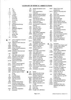

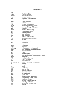


© Copyright 2026