
5AXISMAKER gcode generator V0.21.indd
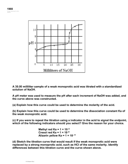
5AXISMAKER Gcode generator
V0.2
Following these steps will help you start in
no time:
1) INTERFACE (gives you a general overview)
2) MACHINE SETUP (gets your 5axis machine ready)
3) GETTING STARTED (this step connects your ge-
ometry to the machine head and generates the gcode that
needs in order to run a machine. Once this step is complete congratulations, you are ready to run your machine!
And of course for customization of settings follow step 3.1
and 3.2)
3.1) TOOLPATH - DETAILED SETUP
3.2) SIMULATION - DETAILED SETUP
to get started, have ready Rhinoceros, Grasshopper and our Grasshopper script open:
AXIS OFFSETS:
This panel lets you set up
your machine’s physical
characteristics
TOOL:
This pannel lets you define
your tool geometry
GEOMETRY:
This pannel lets you choose
geometry to work with
TOOLPATH:
This panel lets you customize toolpath for desired cut
performance
SIMULATION:
this panel gives you control
over how your tool path
curve is interpreted in to
gcode
GCODE:
This panel output gcode for
your cut
1) INTERFACE (basic info on script layout)
3D VIEW:
Displays simulation of machine
head and tool
path on your
model
C axis (roatation around Z axis)
CaxisOffset
B axis (roatation around Y axis)
Use these tabs to set up your machine
and tool characteristics.
BaxisOffset
(Axis offsets are set up by default for
5AXISMAKER and will work with geometry for machine head in the template
file.)
ToolStickOut
2) MACHINE SETUP
Tool Diameter
A.
B.
1. right click on
“Geometry” tab and go to
“set one Geometry”. This
lets you select surface (A)
for cuting from 3d view by
clicking on it.
This will generate tool path
curve (B) on the surface.
C.
2. Activating “simulation toggle” generates coordinate
points for the cut on the toolpath curve and calculates tool
positions for these points (C).
3. You can scroll through tool
positions on the toolpath
using “Simulation” slider.
4. The code for the cut now
appears in “Gcode” panel from
where you can copy and save
3) GETTING STARTED (the gcode is generated, it’s done!)
10mm stepover
5mm stepover
3mm stepover
1mm stepover
Stepover is the distance between parallel segments of
toolpath curve.
This parameter controls the length of the cutting operation
and the surface finish of the cut object.
You can control this distance using “Step Over Distance”
slider.
3.1) TOOLPATH - STEPOVER (these are the additional settings)
V direction toolpath
U direction toolpath
It is possible to change direction of the tool path by switching “U/V direction toggle”. This will align toolpath curve
with either U or V direction of the surface.
TOOLPATH - DIRECTION
5mm seam gap
0.25mm seam gap
“Seam gap” slider adjusts distance between start and end
of toolpath curve segments.
TOOLPATH - SEAM
A.
B.
When toolpath curve does not describe the surface accurately (A.) it could be
because toolpath curve segments do not have enough points to resolve the
geometry accurately.
To add point to toolpath curve segments use “isocurve rebuild” until toolpath
accurately describes your geometry (B.).
However when adding to many points it might slow down the performance of
the simulation
TOOLPATH - ISOCURVE ACURACY
A
B
“Toolpath flip” Option lets you choose from which end of the toolpath
the tool will start moving.
TOOLPATH - FLIP TOOLPATH START POINT
100 points
1000 points
5000 points
When simulation is activated (with “Simulation toggle”) resolution of the cut
can be controlled using “Resolution” slider, which adds coordinate points to
the toolpath curve.
This parameter controls how accurately toolpath describes the surface of the
model since machine moves in straight lines between these points.
3.2) SIMULATION - RESOLUTION
A.
B.
Some particular features may cause collisions between machine head and the
model (A.).
In such cases it might be appropriate to isolate these features to work on the
separately (B.).
SIMULATION - COLLISIONS
To avoid collisions between machine head and the model it is possible to
adjust angle between the tool and the surface using “Lead/Lag angle” and
“Tilt angle” sliders.
SIMULATION - LEAD/LAG AND TILT ANGLES
A.
B.
When tool position is calculated from the wrong side of the surface (A.)
use “Flip surface” toggle to change surface face to the correct one (B.).
SIMULATION - SURFACE DIRECTION
“Vector visibility” toggle turns on display of machine head vectors at
every coordinate point on the toolpath. This can be useful to visualise
envelope of the tool head motion.
SIMULATION - SHOW TOOL VECTORS
custom curve
A.
B.
C.
It is possible to create toolpath from custom curves. Right click on
“Custom toolpath curve” tab and go to “set one curve” and select your
curve. This will define the curve to be used for your custom toolpath.
Use “custom toolpath” toggle to switch between custom toolpath and
automatically generated toolpath.
TOOLPATH - CUSTOM TOOLPATH
curve can be arbitrary
Custom toolpath curve does not have to be on the surface of the model,
it can be a curve drawn by you or any arbitrary curve. Vectors for the tool
will be calculated using normals from the closest point on the surface of
the model to the points on the toolpath curve.
TOOLPATH - CUSTOM TOOLPATH
In this release of 5AXISMAKERgcode generator we started implementation of
support for meshes. However to make use of meshes the script uses a module
that reconstructs mesh geometry in to NURBS geometry. To successfully do that
there are some limitations to mesh geometry that can be used.
These are the types of mesh geometry that can be reconstructed in to NURBS geometry at the moment:
2 Open edges
4 Open edges
A mesh with 2 open edges or with 4 open edges can be sucessfuly converted in to NURBS surfaces.
GEOMETRY - MESHES
Not enough UV curves
Right density of UV curves
5AXISMAKERgcode generator reconstructs mesh geometry in to
NURBS surfaces by creating a set of U and V direction curves on top
of the mesh and then uses this curve network to construct a NURBS
surface.
To show or hide U and V curves used for mesh reconstruction use
“Visibility” toggle.
To make sure that reconstructed surface conforms to the shape of
the original mesh you can adjust U and V curve density using “U
count” and “V count” sliders.
GEOMETRY - MESHES TO NURBS CONVERSION
Base curve pair 1
Base curve pair 2
For mesh geometries with 4 open edges one can select which pair of
edges to use as a base for conversion.
Use “Pair selector” to choose which pair of edges to use.
GEOMETRY - MESHES TO NURBS CONVERSION
Mesh edges are made of lines
Min angle of seperation 45
Min angle of seperation 11
Mesh edges are made of separate line segments that need to be sorted and connected together in to 4 separate curves that define an
edge.
To separate lines of one edge from the lines of another edge we use a
minimum value of angle between the edges. This value can be adjusted using “Min angle of separation” slider.
GEOMETRY - MESHES TO NURBS CONVERSION
Proposed additions to 5AXISMAKER Gcode generator in future
releases:
-
Automatic collision detection
Roughing toolpath generator
Gcode output to file
Formating of Gcode
5AXISMAKER Gcode generator is an open source script and we welcome modifications and improvements to it from the maker community.
Let’s make 5axis machining for everyone a reality!


© Copyright 2026