
as a PDF
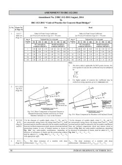
A RHEOLOGICAL MODEL
FOR MAGNETO-RHEOLOGICAL FLUIDS
Daniela Susan-Resiga 1, Ladislau Vékás 2,
Romeo Susan-Resiga 3
Introduction
Magneto-rheological fluids (MRF) are suspensions of particles which can
be magnetized. MRF exhibit fast, strong and reversible changes in their rheological
properties when a magnetic field is applied. A commercially available damping
system that takes full advantage of the controllable technology of MRF and
delivers valveless damping control appeared on passenger vehicles in 2003.
Further commercial systems are e.g. a MRF brake, „steer-by-wire” vehicle control,
controllable friction damper that decreases the noise and vibrations in washing
machines, above-the-knee prosthesis, and seismic mitigation MRF damping
systems protecting buildings and bridges from earthquakes and windstorms.
Goncalves et al. [6] present a recent review of the state of the art in
magnetorheological technology. Since their invention in 1948, MR fluid development has made significant advancements. Throughout this time, MR fluids have
been faced with many challenges and today MR fluid formulations appear to
have overcome many of these challenges. Goncalves et al [6] focus thei review
on strength (i.e. the achievable yield stress), stability and durability of the fluid,
since when using a MR fluid in a particular application these three areas fall
under the greatest scrutiny. The viscoelastic properties of a magneto-rheological
fluid can be variably controlled using a magnetic field. Wollny et al. [13] have
developed a new experimental method allowing an accurate determination of a
magneto-rheological fluid’s viscoelastic properties as a function of the preset
magnetic field strength. Carletto and Bossis [2] attempt to correlate the rheological
characteristics of a magnetic colloidal suspension subjected to a unidirectional
magnetic field with the structures formed within the fluid. As far as the MRF
yield stress is concerned, Bossis et al. conclude that the aggregates do not
break but begin to slip on the wall, then they begin to rotate and no longer touch
the plates. At some critical strain the hydrodynamic shear force will break the
aggregates. This particular behaviour is found in the experimental results we
present in this paper, and it is captured in the mathematical model we propose
1
PhD, Lecturer, West University of Timişoara, Romania
PhD, Senior Researcher, Romanian Academy – Timişoara Branch, Romania
3
PhD, Professor, “Politehnica” University of Timişoara, Romania
2
142
3rd GERMAN-ROMANIAN WORKSHOP on TURBOMACHINERY HYDRODYNAMICS, May 10-12, 2007
to describe the MRF rheology in the presence of the magnetic field. Experimental
investigations on both rheological properties and dispersion stability of MRF have
been performed by Chin et al. [4] as well, in an effort to develop reliable methods
of measurement and analysis able to provide design parameters for practical
devices. The micromechanical properties of a MR system are advocated by
Furst and Gast [5] to be of fundamental importance to the suspension rheology,
especially with regards to the yield stress behaviour. The same viewpoint is
shared by Melle and Martin [8] who develop a chain model based on a balance
of hydrodynamic and magnetostatic forces and focuses on the mechanical
stability of chains.
Most applications of MRF are focused on various damper configurations.
Zhu [14] develop and studies a simple disk-type MRF damper, Fig. 1, and incorporates this technical solution in a flexible rotor system. He proves the effectiveness
of the disk-type MRF damper for attenuating the vibration of the rotor systems
with a simple open-loop on-off control based on the feedback of rotational speed.
Fig. 1. Cross-section of the disk-type MR fluid damper developed by Zhu [14].
Sassi et al. [10] performed theoretical and experimental studies for the
design, development and testing of a MRF damper to be used for semi-active
control of automotive suspensions, Fig. 2.
Various control algorithms and schemes for MRF suspension systems
can be found in [12] and [11].
Our main goal is to develop magnetorheological devices for semi-active
flow control, in particular for mitigating the effects of severe flow instabilities that
occurs in Francis hydraulic turbines operating at part load. As a result, our efforts
are focused on two main issues: i) investigate the flow instabilities and identify
the most effective ways to damp the pressure fluctuations and associated
vibrations, ii) develop special magnetorheological dampers suitable for large
143
3rd GERMAN-ROMANIAN WORKSHOP on TURBOMACHINERY HYDRODYNAMICS, May 10-12, 2007
scale hydraulic turbine applications. As we have shown, the key issue is to
determine experimentally and model mathematically the MRF rheological properties
for variable magnetic field intensity, within a large range of shear strain values.
The present paper presents our latest experimental results together with a novel
mathematical model that accurately captures the MRF rheological behaviour.
Fig. 2. Automotive MRF damper developed by Sassi et al [10].
Magnetorheological investigations
We have investigated the rheological behaviour of the MRF-132DG suspension of micrometer-size particles, using the MCR-300 rheometer with a
plate-plate magneto-rheological cell. A 0.5mm gap has been chosen for all
investigations, corresponding to a 0.157 ml probe volume. Both oscillatory
(amplitude sweep and frequency sweep) and rotational (flow curve, creep test,
relaxation test, temperature test) test have been performed. All tests have been
performed for variable magnetic field intensity, corresponding to the electric
current intensity in the cell coil of 0,0.25,0.5,0.75,1.0,1.5, 2.0,and 3.0 A .
144
3rd GERMAN-ROMANIAN WORKSHOP on TURBOMACHINERY HYDRODYNAMICS, May 10-12, 2007
Fig. 3 shows the primary experimental results from rotational tests, for the
above electric current intensities. In order to capture the behaviour of the MRF
at lower shear rates, oscillatory tests have been performed, as shown in Fig. 4.
So far we have found that only the results from amplitude sweep oscillatory tests
merge with the viscosity curves from rotational tests. These combined data are
used in the next section to develop a mathematical model describing the MRF
−6
3
rheological behaviour within a very large range of shear rate values γ = 10 …10 .
US 200
7
5
10
10
Pa·s
Pa
6
10
4
10
5
10
4
10
η
3
10
τ
3
10
2
10
2
10
1
10
1
10
0
10
-1
10
0
-3
10
-2
10
-1
10
0
10
1
10
2
132DG, FlowC, 0.5mm, 0A 1
132DG, FlowC, 0.5mm, 1
PP 20/MR d=0.5 mm
PP 20/MR d=0.5 mm
η
Viscosity
η Viscosity
τ
Shear Stress
τ
Shear Stress
132DG, FlowC, 0.5mm, 0.75A 1
132DG, FlowC, 0.5mm, 1
PP 20/MR d=0.5 mm
PP 20/MR d=0.5 mm
η
Viscosity
η Viscosity
τ
Shear Stress
τ
Shear Stress
132DG, FlowC, 0.5mm, 0.25A 1
132DG, FlowC, 0.5mm, 2
PP 20/MR d=0.5 mm
PP 20/MR d=0.5 mm
η
Viscosity
η Viscosity
τ
Shear Stress
τ
Shear Stress
132DG, FlowC, 0.5mm, 0.5A 1
132DG, FlowC, 0.5mm, 3
PP 20/MR d=0.5 mm
PP 20/MR d=0.5 mm
η
Viscosity
η Viscosity
τ
Shear Stress
τ
Shear Stress
10
3
10 1/s 10
.
Shear Rate γ
Fig. 3. Experimental data for flow curves and viscosity curves from rotational
−3
3
experiments, with shear rate within the range γ = 10 …10 .
Rheological behaviour of the MRF-132DG
Magneto-rheological fluids (MRF) have a complex behaviour in the presence
of a magnetic field. Chadhuria et al. [3] investigate the rheological flow curves
(shear stress vs. Shear rate) of a nanoparticle cobalt-based magnetorhelogical
fluid, and found that either Bingham-plastic or Herschel-Bulkley models can be
used to describe the experimental data.
145
3rd GERMAN-ROMANIAN WORKSHOP on TURBOMACHINERY HYDRODYNAMICS, May 10-12, 2007
Fig. 4. Experimental data for viscosity curves from oscillatory experiments
(amplitude sweep and frequency sweep) and rotational experiments.
The experimental investigations we have performed on a MRF-132DG
probe reveals a quasi-newtonian behaviour in the start-up phase, with very low
146
3rd GERMAN-ROMANIAN WORKSHOP on TURBOMACHINERY HYDRODYNAMICS, May 10-12, 2007
shear rate, switching in a shear-thinning behaviour as the shear rate increases.
As a result, the mathematical model to be used for fitting the experimental data
should capture this transition as
τ (γ ) = τ N (γ ) W1 (γ ) + τ HB (γ ) W2 (γ )
(1)
where the Newtonian behaviour is given by
τ N (γ ) = η0γ ,
(2)
and the shear thinning behaviour is described by the Hershel-Bulkley model,
τ HB (γ ) = τ 0 + cγ 1−n .
(3)
The Hershel-Bulkley model assumes a yield stress
τ 0 , and for shear-
thinning fluids n < 1 . The consistency constant c is a fit parameter.
The weighting functions W1 (γ ) and W2 (γ ) in Eq.(1) should be chosen
such as W1 (γ )
W2 (γ ) for very low shear rate, and W1 (γ )
W2 (γ ) at large
shear rate, with W1 (γ ) + W2 (γ ) = 1 . There are many continuous, with continuous
derivatives, functions that meet the above general requirements. Note that the
function and its derivatives continuity insures a smooth transition between the
two different behaviours (2) and (3), as observed in experiments.
∗
Let us assume that γ is a shear rate value in the neighborhood of the
transition between the Newtonian and Hershel-Bulkley models. This characteristic
value will be used in our model to make the shear rate dimensionless, thus rewriting the Hershel-Bulkley model as
1− n
⎛γ ⎞
τ HB (γ ) = τ 0 + τ 1 ⎜ ∗ ⎟
⎝γ ⎠
.
(4)
Note that the consistency constant in Eq.(3) has been replaced by the
parameter τ 1 with dimension of shear stress.
The function that blends the two models will depend on the dimensionless
∗
variable x ≡ γ / γ , and it can be chosen as tanh ( x ) , or erf ( x ) , or 1 − exp ( − x ) ,
or any other function with the qualitative behaviour as in Fig. 5. For example,
the 1 − exp ( − x ) function has been used by Papanastasiou [9] to modify the
viscoplastic fluid models in order to avoid the discontinuity in the flow curve due
to the incorporation of the yield criterion [7]. As a result, a single equation can
be used for the entire flow curve, before and after yield, as follows
⎧
τ (γ ) = ⎨η +
⎩
τ y [1 − exp( − aγ ) ] ⎫
⎬γ .
γ
⎭
(5)
147
3rd GERMAN-ROMANIAN WORKSHOP on TURBOMACHINERY HYDRODYNAMICS, May 10-12, 2007
1
0.9
blending function
0.8
0.7
0.6
erf(x)
tanh(x)
1−exp(−x)
0.5
0.4
0.3
0.2
0.1
0
0
0.5
1
1.5
x
2
2.5
3
Fig. 5. Blending functions.
All the above functions vanish as x → 0 and reach the asymptotic value
of 1 for x → ∞ . However, one can control how fast the functions approach the
asymptotic value by stretching the abscissa with a parameter multiplying x . The
∗
role of this parameter is played in out model by the characteristic shear rate γ .
For the present analysis we have chosen
⎛γ ⎞
⎛γ ⎞
W1 = 1 − tanh ⎜ ∗ ⎟ and W2 = tanh ⎜ ∗ ⎟ ,
⎝γ ⎠
⎝γ ⎠
(6)
but similar results are obtained with the other choices mentioned above. As a
result, the mathematical model used for representing the mahneto-rheological
behaviour of the MRF-132DG samples reads as
1− n
⎡
⎛ γ ⎞⎤ ⎡
⎛γ ⎞ ⎤
⎛γ ⎞
τ = η0γ ⎢1 − tanh ⎜ ∗ ⎟ ⎥ + ⎢τ 0 + τ 1 ⎜ ∗ ⎟ ⎥ tanh ⎜ ∗ ⎟ .
⎝ γ ⎠ ⎦ ⎢⎣
⎝ γ ⎠ ⎥⎦
⎝γ ⎠
⎣
(7)
Fig. 6 shows that the results obtained by replacing the tanh ( x ) in Eq.(7)
either by erf ( x ) or 1 − exp ( − x ) are practically identical, but obviously there
are some changes in the fit parameter values.
The shear stress vanishes as γ → 0 , while the viscosity
limit value for vanishing shear rate
η ∗ ≡ limη = η0 +
γ →0
Equation
τ0
.
γ∗
η ≡ τ / γ has the
(8)
(8) clearly reveals that the start-up viscosity η ∗ incorporates
both the contribution from the Newtonian behaviour, η0 , and the contribution from
the yield stress of the Hershel-Bulkley model,
τ0 .
148
3rd GERMAN-ROMANIAN WORKSHOP on TURBOMACHINERY HYDRODYNAMICS, May 10-12, 2007
Fig. 6. Flow curve fitted with various blending functions.
The shear stress reaches the characteristic value of
τ ∗ ≡ τ (γ ∗ ) = η0γ ∗ × 0.2384 + (τ 0 + τ 1 ) × 0.7616
(9)
at the characteristic shear rate value, corresponding to the shift in the rheological
behaviour from quasi-Newtonian to shear-thinning.
Although our model (7) has five parameters to be found by fitting the
experimental data, four of them are relevant from practical point of view: the
∗
∗
threshold shear rate γ and the corresponding shear stress τ , the start-up
viscosity
η ∗ , and the shear-thinning exponent n . The latest was found to have
practically the same value, n = 0.855 ( ±3% ) for a wide range of electric current
intensity in the magneto-rheological cell coil I = 0.25… 3 A , and it has been
subsequently fixed to a value of n = 0.855 .
Fig. 7 through Fig. 13 show the flow curves (shear stress vs. shear rate)
and viscosity curves (dynamic viscosity vs. shear rate) for variable intensity of
the electric current in the magnetorheological cell coil. On the flow curve plots
∗
∗
both τ and γ are marked with dashed lines, since these values correspond
to the quasi-yield point. On the viscosity curve plots we have marked both
and
η∗
γ ∗ are shown explicitly, in order to emphasize the start-up viscosity level
149
3rd GERMAN-ROMANIAN WORKSHOP on TURBOMACHINERY HYDRODYNAMICS, May 10-12, 2007
Fig. 7. Flow curve
τ (γ ) and viscosity curve η (γ ) for I = 0.25 A .
150
3rd GERMAN-ROMANIAN WORKSHOP on TURBOMACHINERY HYDRODYNAMICS, May 10-12, 2007
Fig. 8. Flow curve
τ (γ ) and viscosity curve η (γ ) for I = 0.5 A .
151
3rd GERMAN-ROMANIAN WORKSHOP on TURBOMACHINERY HYDRODYNAMICS, May 10-12, 2007
Fig. 9. Flow curve
τ (γ ) and viscosity curve η (γ ) for I = 0.75 A .
152
3rd GERMAN-ROMANIAN WORKSHOP on TURBOMACHINERY HYDRODYNAMICS, May 10-12, 2007
Fig. 10. Flow curve
τ (γ ) and viscosity curve η (γ ) for I = 1.0 A .
153
3rd GERMAN-ROMANIAN WORKSHOP on TURBOMACHINERY HYDRODYNAMICS, May 10-12, 2007
Fig. 11. Flow curve
τ (γ ) and viscosity curve η (γ ) for I = 1.5 A .
154
3rd GERMAN-ROMANIAN WORKSHOP on TURBOMACHINERY HYDRODYNAMICS, May 10-12, 2007
Fig. 12. Flow curve
τ (γ ) and viscosity curve η (γ ) for I = 2.0 A .
155
3rd GERMAN-ROMANIAN WORKSHOP on TURBOMACHINERY HYDRODYNAMICS, May 10-12, 2007
Fig. 13. Flow curve
τ (γ ) and viscosity curve η (γ ) for I = 3.0 A .
156
3rd GERMAN-ROMANIAN WORKSHOP on TURBOMACHINERY HYDRODYNAMICS, May 10-12, 2007
and the shear-rate where the rheological behaviour switches from quasi-Newtonian
(in fact weakly shear-thickening) to shear-thinning. A synoptic perspective of
the viscosity variation with the intensity of the magnetic field (proportional with
the intensity of the electric current in the coil) is shown in Fig. 14. One can easily
see a large jump in viscosity values even when a rather weak magnetic field is
applied, and a rapid saturation as the intensity is increased.
Fig. 14. Viscosity curves for variable electric current intensity.
The main parameters, namely the yield stress τ and start-up viscosity η
are plotted in Fig. 15 and Fig. 16, respectively, versus the electric current intensity.
∗
∗
Conclusions
Extensive experimental investigations have been performed in order to
describe the rheological behaviour of a magneto-rheological fluid within magnetic
field of variable strenght. Both oscillatory and rotational tests are employed in
order to explore a large range of shear rate values.
A new rheological model is developed, by combining a Newtonian behaviour
for very low shear rate with a Hershel-Bulkley model for large shear rate. Our
five parameter model, Eq.(7), accurately captures the flow curve and automatically
∗
identifies the shear rate γ where the abrupt qualitative change in the rheological
τ ∗ can be considered to
∗
correspond to the so-called yield stress. However, for γ < γ the MRF displays
∗
a quasi constant (in fact a weak shear-thickening behaviour) large viscosity η ,
behaviour occurs. The corresponding shear stress
157
3rd GERMAN-ROMANIAN WORKSHOP on TURBOMACHINERY HYDRODYNAMICS, May 10-12, 2007
Fig. 15. Yield stress
τ ∗ versus the electric current intensity.
Fig. 16. Start-up viscosity
η ∗ versus the electric current intensity.
which confirms Bossis et al. [1] conclusions that the magnetic particle aggregates
do not break but begin to slip on the wall, then they begin to rotate and no
longer touch the plates, and at some critical strain the hydrodynamic shear
force will break the aggregates.
158
3rd GERMAN-ROMANIAN WORKSHOP on TURBOMACHINERY HYDRODYNAMICS, May 10-12, 2007
Acknowledgements
The present work has been supported by the Romanian Government –
Ministry of Education and Research, National Authority for Scientific Research
through project CEEX-M1-C2-1185 contract No. 64/2006-2008 “iSMART-flow”
and by the Swiss National Science Foundation through the SCOPES Joint
Research Project IB7320-110942.
References
[1] Bossis, G., Khuzir, P., Lacis, S., and Volkova, O., 2003, „Yield behaviour of
magnetorheological suspensions”, Journal of Magnetism and Magnetic Materials,
258-259, pp. 456-458.
[2] Carletto, P., and Bossis, G., 2003, „Field-induced structures and rheology of a
magnetorheological suspension confined between two walls”, J. Phys.: Condens.
Matter, 15, pp. 1437-1449.
[3] Chaudhuria, A., Wereleya, N.M., Kothab, S., Radhakrishnanb, R., and Sudarshanb
N.M., 2005, „Viscometric characterization of cobalt nanoparticle-based
magnetorhelogical fluids using genetic algorithms”, Journal of Magnetism and
Magnetic Materials, Vol.293, Issue 1, pp. 206-214.
[4] Chin, B.D., Park, J.H., Kwon, M.H., and Park, O.O., 2001, „Rheological properties
and dispersion stability of magnetorheological (MR) suspensions”, Rheologica
Acta, 40, pp. 211-219.
[5] Furst, E.M., and Gast, A.P., 2000, „Micromechanics of magnetorhelogical
suspensions”, Physical Review E, Vol.61, No.6, pp. 6732-6739.
[6] Goncalves, F.D., Koo, J.-H., and Ahmadian, M., 2006, „A Review of the State
of the Art in Magnetorheological Fluid Technologies – Part I: MR fluid and MR
fluid models”, The Shock and Vibration Digest, Vol.38, No.3, 203-219.
[7] Macosko, C.W., 1994, RHEOLOGY. Principles, Measurements, and Applications,
Wiley-VCH, New York.
[8] Melle, S., and Martin, J.E., 2003, „Chain model of a magnetorheological suspension
in a rotating field”, Journal of Chemical Physics, Vol.118, No.21, pp. 9875-9881.
[9] Papanastasiou, T.C., 1987, J. Rheology, 31, p.385.
[10] Sassi, S., Cherif, K., Mezghani, L., Thomas, M., and Kotrane, A., 2005, „An
innovative magnetorheological damper for automotive suspension: from design to
experimental characterization”, Smart Materials and Structures, 14, pp. 811-822.
[11] Shen, Y., Golnaraghi, M.F., and Heppler, G.R., 2006, „Semi-active Vibration
Control Schemes for Suspension Systems Using Magnetorheological Dampers”,
Journal of Vibration and Control, 12(1), pp. 3-24.
[12] Song, X., Ahmadian M., Southward, S., and Miller, L.R., 2005, „An Adaptive
Semiactive Control Algorithm for Magnetorheological Suspension Systems”,
Journal of Vibration and Acoustics, Vol. 127, pp.493-502.
[13] Wollny, K., Läuger, J. And Huck, S., 2002, „Magneto Sweep – A New Method
for Characterizing the Viscoelastic Properties of Magneto-Rheological Fluids”,
Applied Rheology, Vol.12, No.1, pp.25-31.
[14] Zhu, C., 2005, „A disk-type magneto-rheological fluid damper for rotor system
vibration control”, Journal of Sound and Vibration, 283, pp. 1051-1069.


© Copyright 2026